Being in technology for a long time, I have seen my fair share of disk failures. However I have never seen a single instance where SMART has issued a sufficient warning to backup any data on a failing disk. The following is an example of this in action.
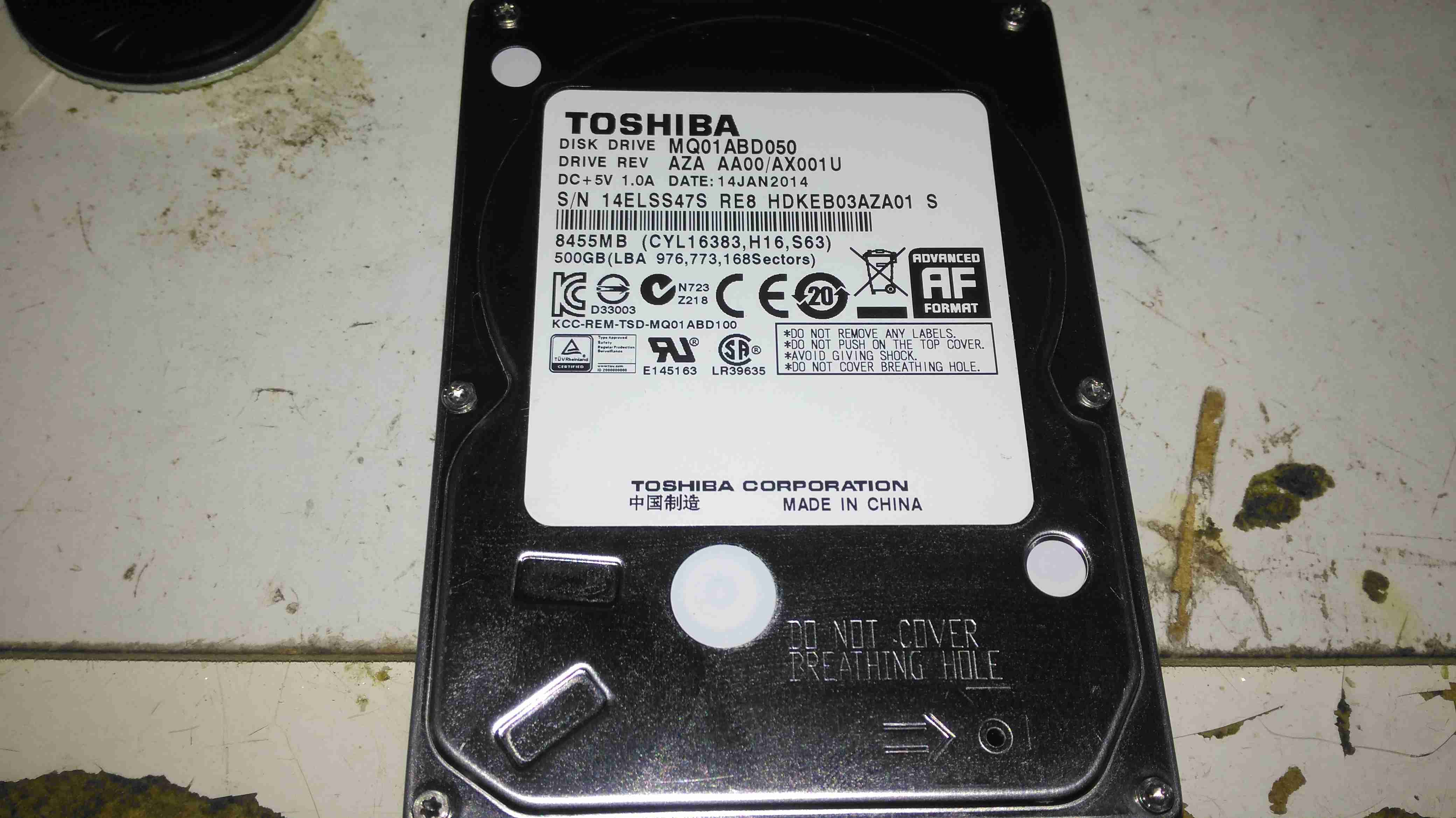
Toshiba MQ01ABD050
Here is a 2.5″ Toshiba MQ01ABD050 500GB disk drive. This unit was made in 2014, but has a very low hour count of ~8 months, with only ~5 months of the heads being loaded onto the platters, since it has been used to store offline files. This disk was working perfectly the last time it was plugged in a few weeks ago, but today within seconds of starting to transfer data, it began slowing down, then stopped entirely. A quick look at the SMART stats showed over 4000 reallocated sectors, so a full scan was initiated.
SMART Test Failure
After the couple of hours an extended test takes, the firmware managed to find a total of 16,376 bad sectors, of which 10K+ were still pending reallocation. Just after the test finished, the disk began making the usual clicking sound of the head actuator losing lock on the servo tracks. Yet SMART was still insisting that the disk was OK! In total about 3 hours between first power up & the disk failing entirely. This is possibly the most sudden failure of a disk I’ve seen so far, but SMART didn’t even twig from the huge number of sector reallocations that something was amiss. I don’t believe the platters are at fault here, it’s most likely to be either a head fault or preamp failure, as I don’t think platters can catastrophically fail this quickly. I expected SMART to at least flag that the drive was in a bad state once it’s self-test completed, but nope.
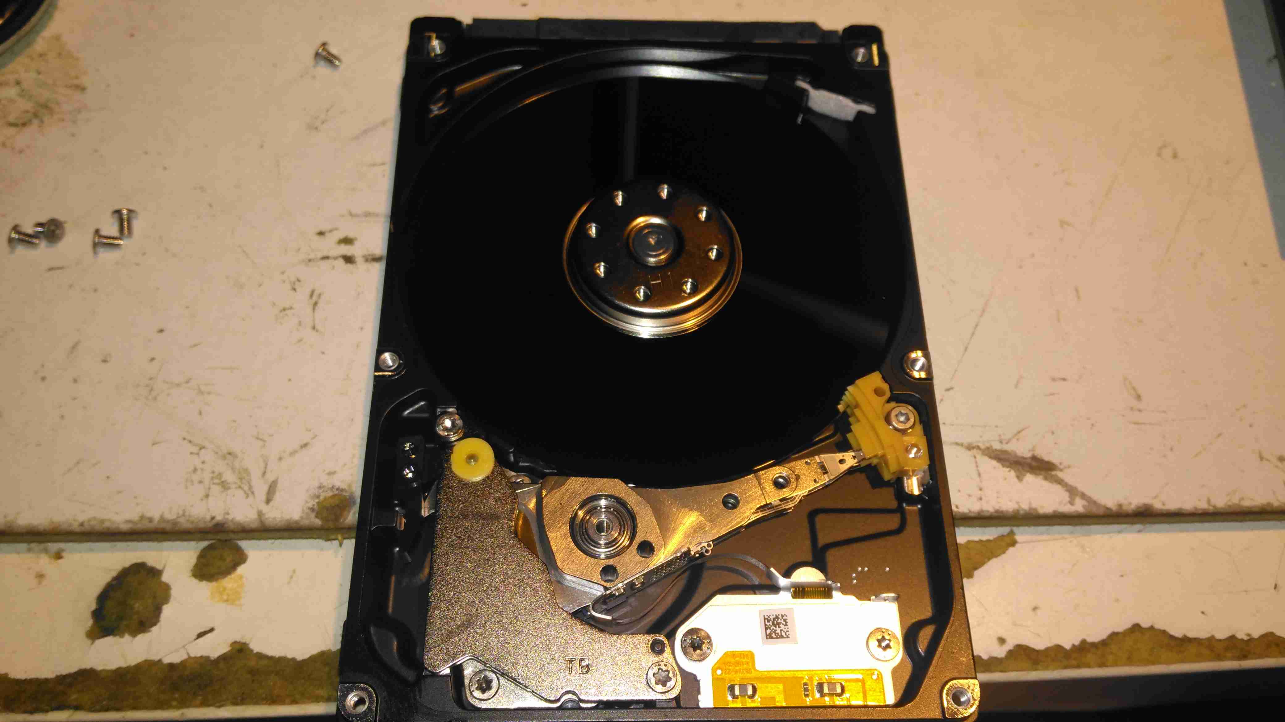
Internals
After pulling the lid on this disk, to see if there’s any evidence of a head crashing into a platter, there’s nothing – at least on a macroscopic scale, the single platter is pristine. I’ve seen disks crash to the point where the coating has been scrubbed from the platters so thoroughly that they’ve been returned to the glass discs they started off as, with the enclosure packed full of fine black powder that used to be data layer, but there’s no indication of mechanical failure here. Electronic failure is looking very likely.
Clearly, relying on SMART to alert when a disk is about to take a dive is an unwise idea, replacing drives after a set period is much better insurance if they are used for critical applications. Of course, current backups is always a good idea, no matter the age of drive.
With the installation of the new diesel fired heater we’ve noticed a small problem – since the only heat source in the saloon is the stove, even with the diesel heater fired up the temperature doesn’t really change much, as the heat from the radiators in the both the cabins & the head isn’t spreading far enough.
The solution to this problem is obviously an extra radiator in the saloon, however there isn’t the space to fit even a small domestic-style radiator. eBay turned up some heater matrix units designed for kit cars & the like:
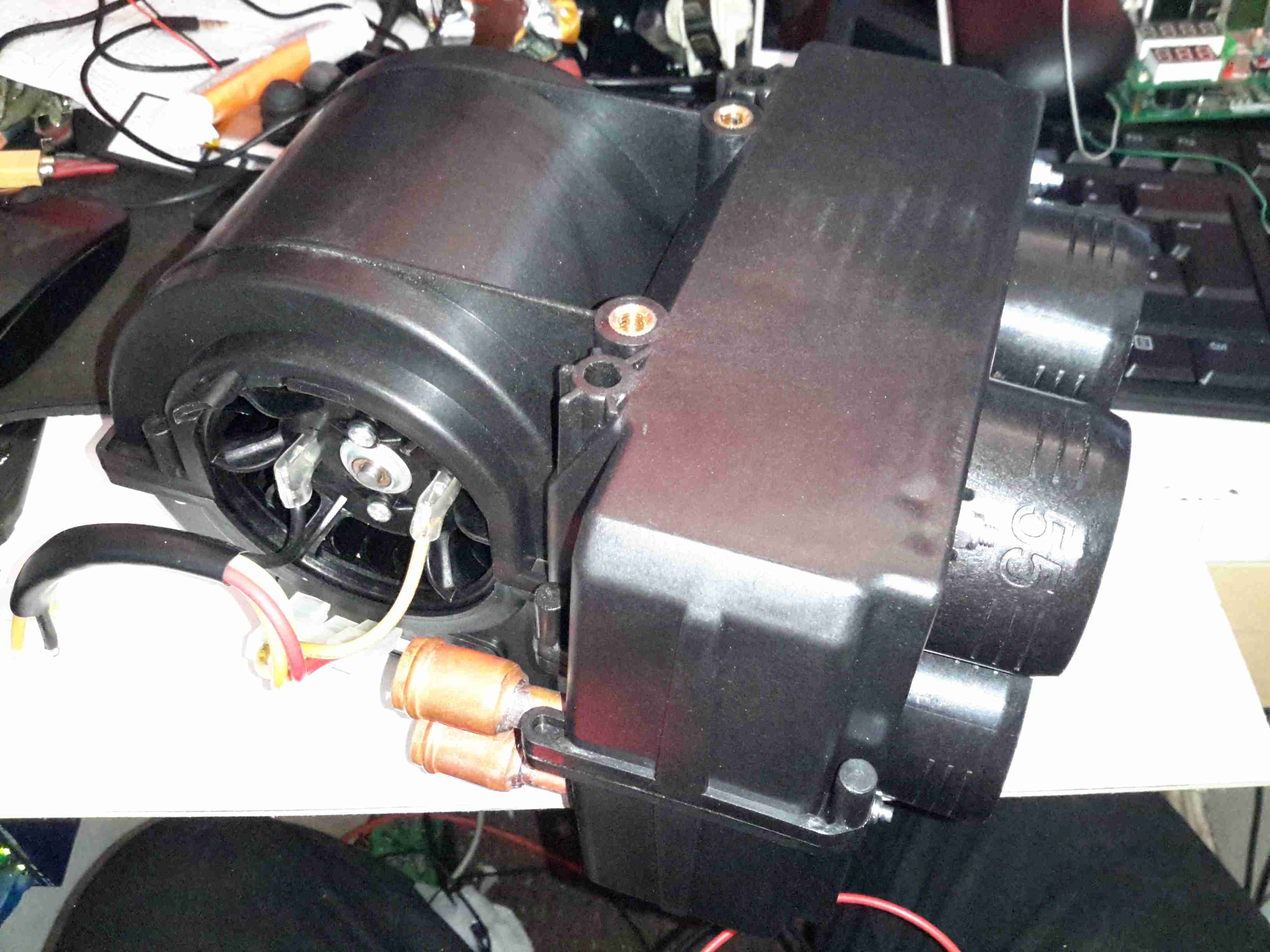
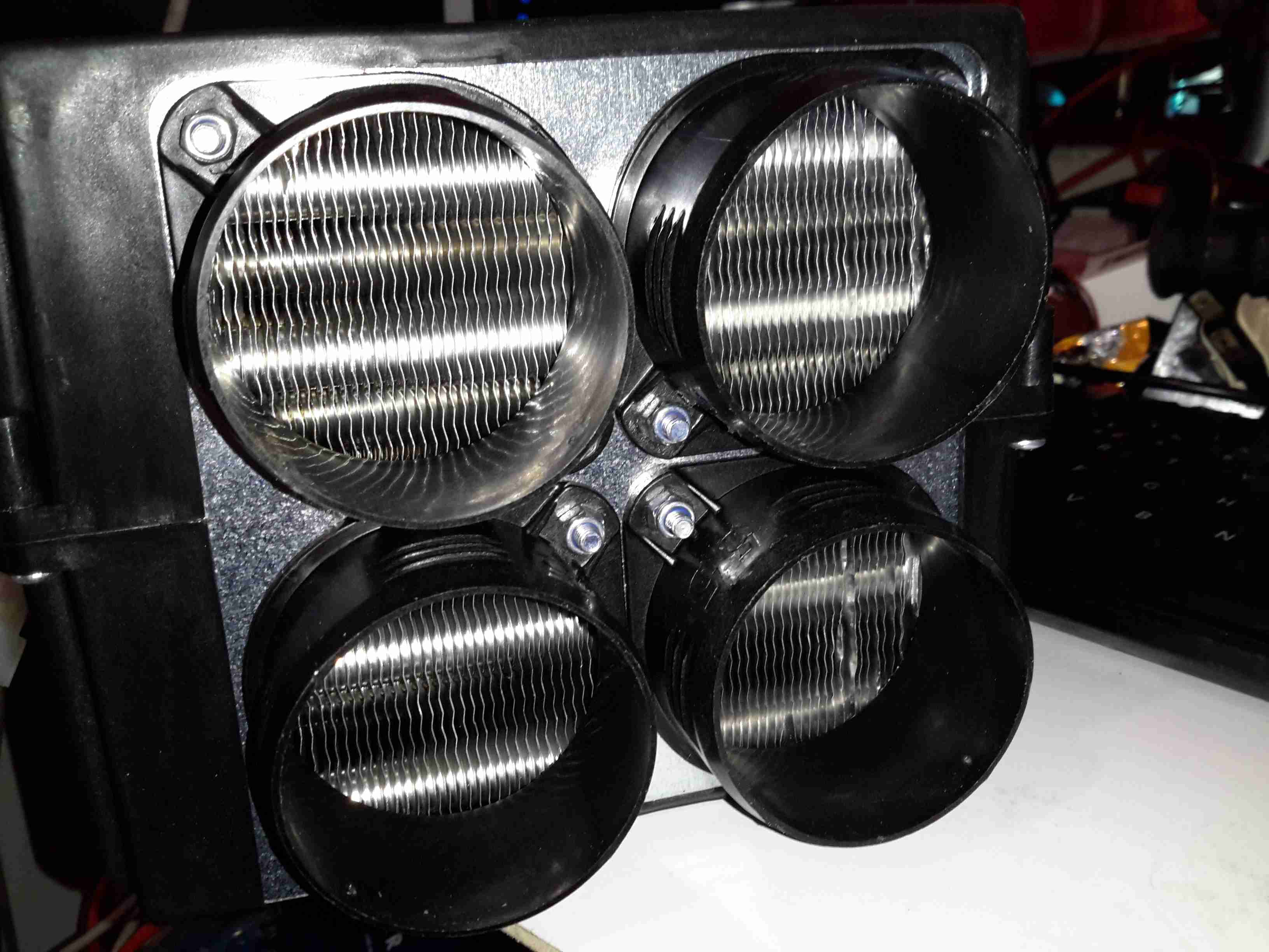
3.8kW Matrix
These small heater matrix units are nice & compact, so will fit into the back of a storage cupboard next to the saloon. Rated at a max heat output of 3.8kW, just shy of the stove’s rated 4kW output power, this should provide plenty of heating when we’re running the diesel heater rather than the fire.
Water & Power
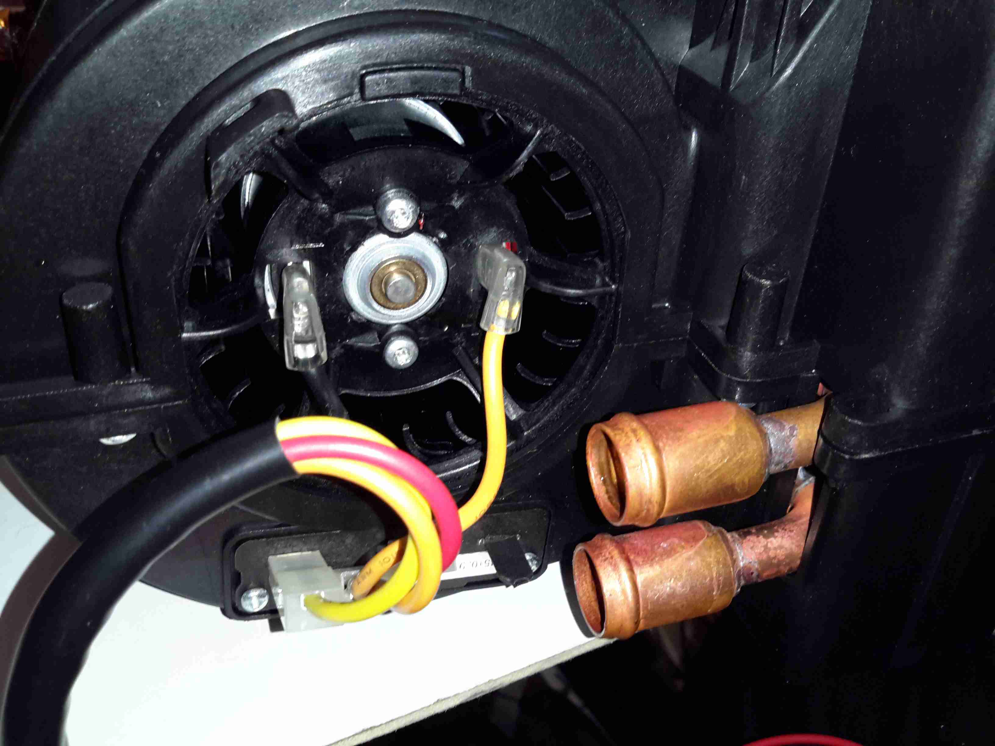
The blower motor has a resistor network to provide 3 speeds, but this probably won’t be used in this install, water connections are via 15mm copper tails. The current plan is to use a pipe thermostat on the flow from the boiler to switch on the blower when the water temperature reaches about 40°C.
Hot Air Outlets
The hot air emerges from the matrix via 4 55mm duct sockets. This gives enough outlets to cover both the saloon & the corridor down to the cabins.
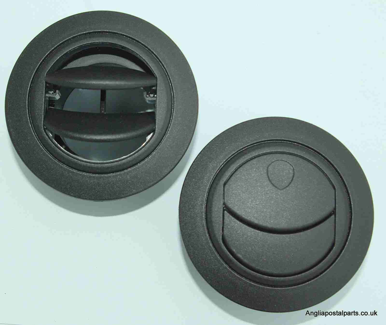
Hot Air Vents
Standard 60mm Eberspacher style vents will be used to point the warmth where it’s needed.
With some recent upgrades to the boat’s heating system, the hot water circulation pumps we’ve been using are becoming far too small for the job. After the original Johnson Marine circulation pump died of old age (the brushes wore down so far the springs ate the commutator) some time ago, it was replaced with a Pierburg WUP1 circulation pump from a BMW. (As we’re moored next to a BMW garage, these are easily obtainable & much cheaper than the marine pumps).
WUP1 Cutaway
These are also brushless, where as the standard Johnson ones are brushed PM motors – the result here is a much longer working life, due to fewer moving parts.
The rated flow & pressure on these pumps is pretty pathetic, at 13L/min at 0.1bar head pressure. As the boat’s heating system is plumbed in 15mm pipe instead of 22mm this low pressure doesn’t translate to a decent flow rate. Turns out it’s pretty difficult to shove lots of water through ~110ft of 15mm pipe ;). Oddly enough, the very low flow rate of the system was never a problem for the “high output” back boiler on the stove – I suspect the “high output” specification is a bit optimistic.
This issue was recently made worse with the addition of a Webasto Thermo Top C 5kW diesel-fired water heater, which does have it’s own circulation pump but the system flow rate was still far too low to allow the heater to operate properly. The result was a rapidly cycling heater as it couldn’t dump the generated hot water into the rest of the system fast enough.
The easiest solution to the problem here is a larger pump with a higher head pressure capability. (The more difficult route would be completely re-piping the system in 22mm to lower the flow resistance). Luckily Pierburg produce a few pumps in the range that would fit the job.
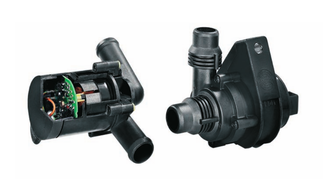
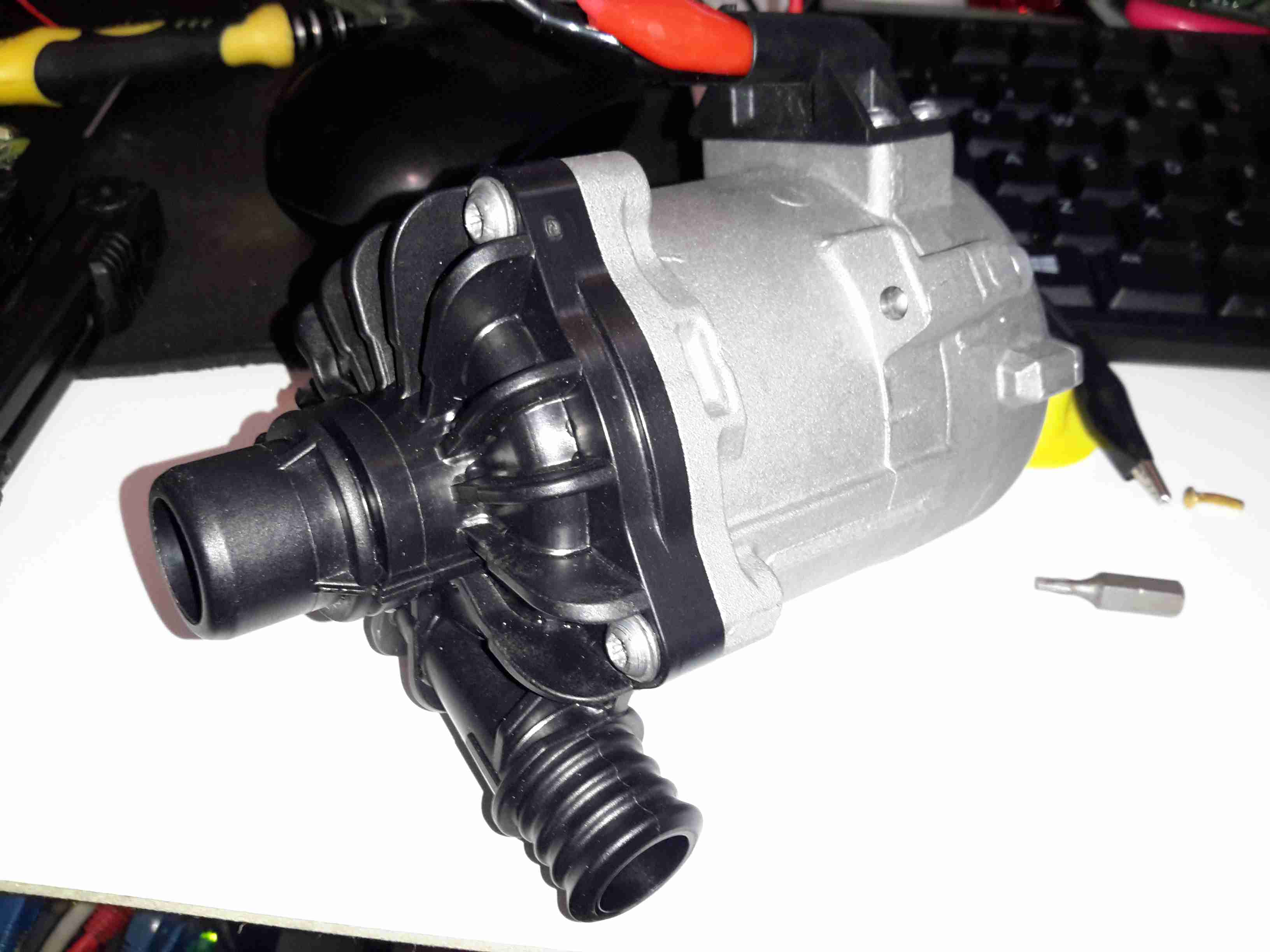
Pierburg CWA-50
Here’s the next size up from the original WUP1 pump, the CWA50. These are rated at a much more sensible 25L/min at 0.6bar head pressure. It’s physically a bit larger, but the connector sizes are the same, which makes the install onto the existing hoses easier. (For those that are interested, the hose connectors used on BMW vehicles for the cooling system components are NormaQuick PS3 type. These snap into place with an O-Ring & are retained by a spring clip).
The CWA50 draws considerably more power than the WUP1 (4.5A vs 1.5A), and are controllable with a PWM signal on the connector, but I haven’t used this feature. The PWM pin is simply tied to the positive supply to keep the pump running at maximum speed.
Once this pump was installed the head pressure immediately increased on the gauge from the 1 bar static pressure to 1.5 bar, indicating the pump is running at about it’s highest efficiency point. The higher water flow has so far kept the Webasto happy, there will be more to come with further improvements!
CWA-50 Pump Teardown
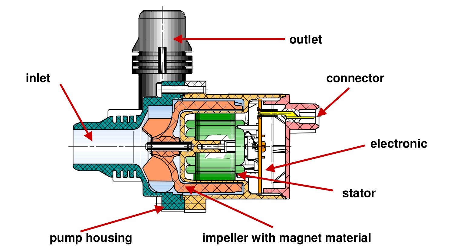
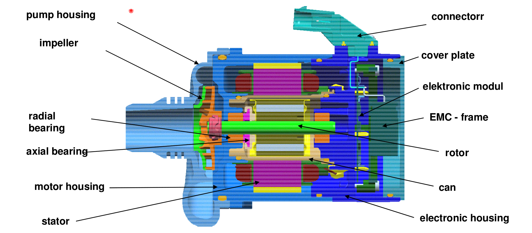
CWA50 Cutaway
Above is a cutaway drawing of the new pump. These have a drilling through the shaft allows water to pass from the high pressure outlet fitting, through the internals of the pump & returns through the shaft to the inlet. This keeps the bearings cool & lubricated. The control & power drive circuitry for the 3-phase brushless motor is attached to the back & uses the water flowing through the rotor chamber as a heatsink. Overall these are very well made pumps.
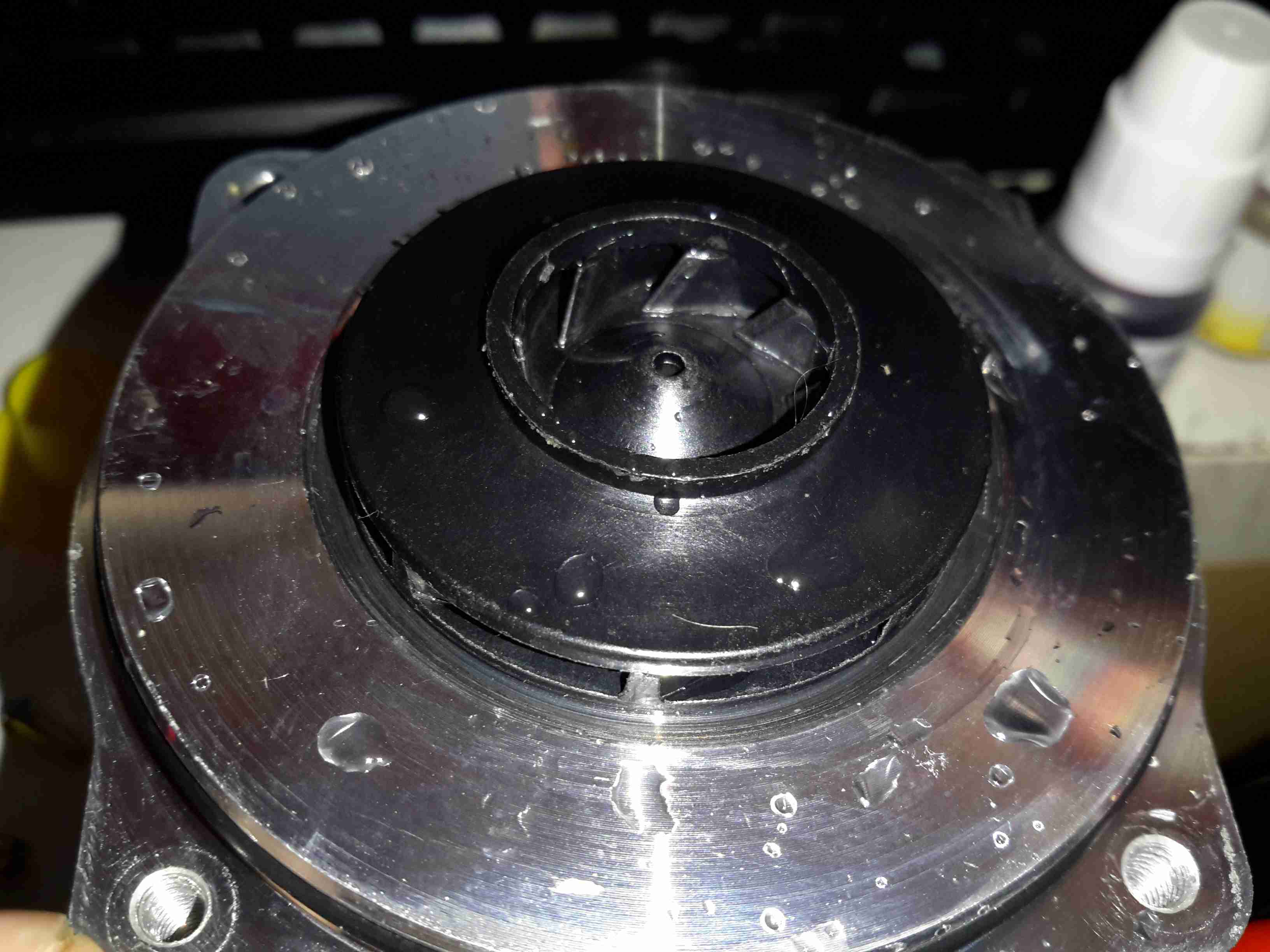
Impeller
Here’s the impeller of the pump, which is very small considering the amount of power this unit has. The return port for the lubricating water can be seen in the centre of the impeller face.
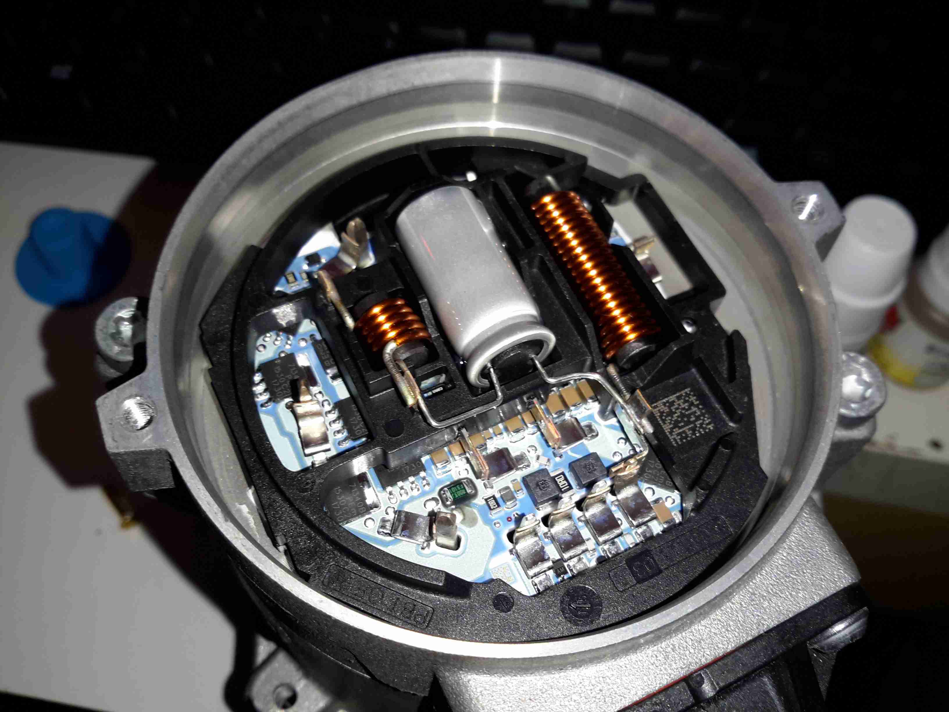
3-Phase Driver
Inside the back of the pump is the control module. The main microcontroller is hiding under the plastic frame which holds the large power chokes & the main filter electrolytic.
In a word, no they aren’t any good. As usual, cheap doesn’t equal good, and in this case the cheapo clones are a total waste of money. Read on for the details!
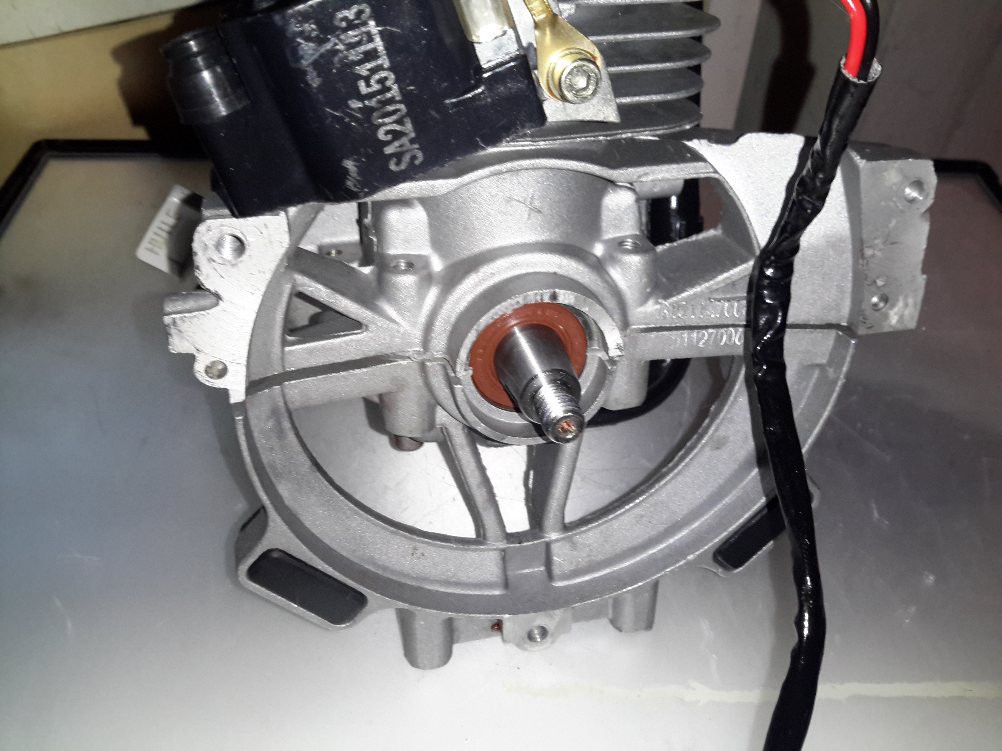
I’ve been looking into using a cheap Chinese clone Honda GX35 engine to drive an automotive alternator as a portable battery charging & power unit. These engines are available very cheaply on eBay, aimed at the mini-bike/go-kart market.
For those not in the know, the Honda GX25/35 4-strokes are strimmer-type engines that traditionally were always of 2-stroke construction. Honda worked out how to have a wet-sump engine without the need to keep the engine always in the “upright” position. They do not require mixing of oil into the fuel for lubrication as 2-strokes do, so should be much cleaner running.
So far I’ve had two of these cheap engines, as the first one died after only 4 hours run time, having entirely lost compression. At the time the engine was idling, no load, having been started from cold only a few minutes before. Having checked the valve clearances to make sure a valve wasn’t being held partially open, I deduced that the cause was broken piston rings. This engine was replaced by the seller, so I didn’t get a chance to pull it to bits to find out, but I decided to do a full teardown on the replacement to see where the cloners have cut corners.
Oil Return Hose
I’ve already stripped off the ancillary components: exhaust, carburettor, fuel tank, cowlings, as these parts are standard to any strimmer engine. The large black hose here is the oil return feed back to the rocker cover from the crankcase. The oiling system in these engines is rather clever. The main engine block is made of light alloy, probably some permutation of Aluminium. There is much flashing left behind between the cylinder fins from the die-casting process, and not a single engine manufacturer’s logo anywhere. (From what I’ve read, the genuine Honda ones have their logo on the side of the crankcase).
Rocker Box
Here’s the top of the engine with valves, rockers & camshaft. All the valve gear up here, minus the valves themselves & springs, are manufactured from sintered steel, there are no proper “bearings”, the steel shafts just run in the aluminium castings. The cam gear is of plastic, with the sintered steel cam pressed into place. The cam also has the bearing surface for the pin that the whole assembly rotates on. The timing belt runs in the oil & is supposed to last the life of the engine, and while I’d believe that in the original Honda, I certainly wouldn’t in this engine. The black grommet is the opening of the oil return gallery.
Cam
Here’s the cam on the back of the plastic pulley. A single cam is used for both intake & exhaust valves for space & simplicity.
Intake Valve Stem Seal
Just visible under the intake valve spring is a simple stem seal, to hopefully prevent oil being sucked down the valve guide into the cylinder by intake vacuum. Running these cheap engines proves this seal to be ineffective, as they blow about as much blue oil smoke as a 2-stroke when they’re started cold. 😉
Starter Side
The starter side is where the oil sump is located on these engines, along with the dipstick.
Flywheel Side
The flywheel end of the engine is the usual fare for small engines. Ignition is provided by a magneto, with a magnet in the flywheel. This is no different from the 2-stroke versions. As these ignitions fire on every revolution of the crankshaft, the spark plug fires both on compression, igniting the fuel for normal operation, and again into the exhaust stroke, where the spark is wasted.
One thing I have noticed about these engines is an almost total lack of cooling air coming through the cowling over the cylinder cooling fins. Plenty was flowing over the exhaust silencer side, I believe bad housing design would be what causes this problem. A lack of cooling certainly wouldn’t help engine longevity!
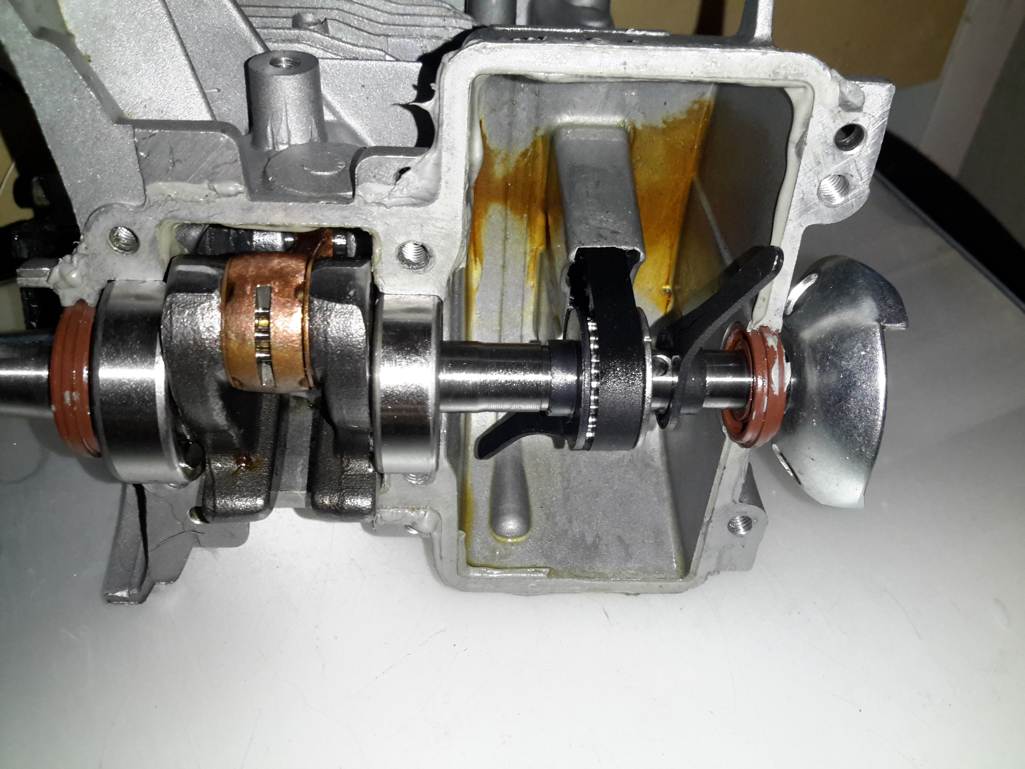
Engine “Sump”
Separating the bottom of the engine was a little difficult, as there is a significant bead of sealant used instead of a gasket. Inside the sump of the engine are a pair of paddles, which stir up the oil into a mist. As the piston moves in the cylinder, it acts as a pump, creating alternating pulses of pressure & vacuum in the crankcase. Oil mist flows through a drilling in the crank from the sump, into the crankcase where it (hopefully) lubricates the bearings & the cylinder wall. Incidentally, the only main bearings are on the crankcase – the far end of the shaft that carries the oil paddles & timing belt is just flapping in the breeze, the only support being the oil seal in the outer housing. The crank itself isn’t hardened – a file easily removes metal from all parts that I could get at. The big end journal pin might be, but these cranks are pressed together so I can’t access that part.
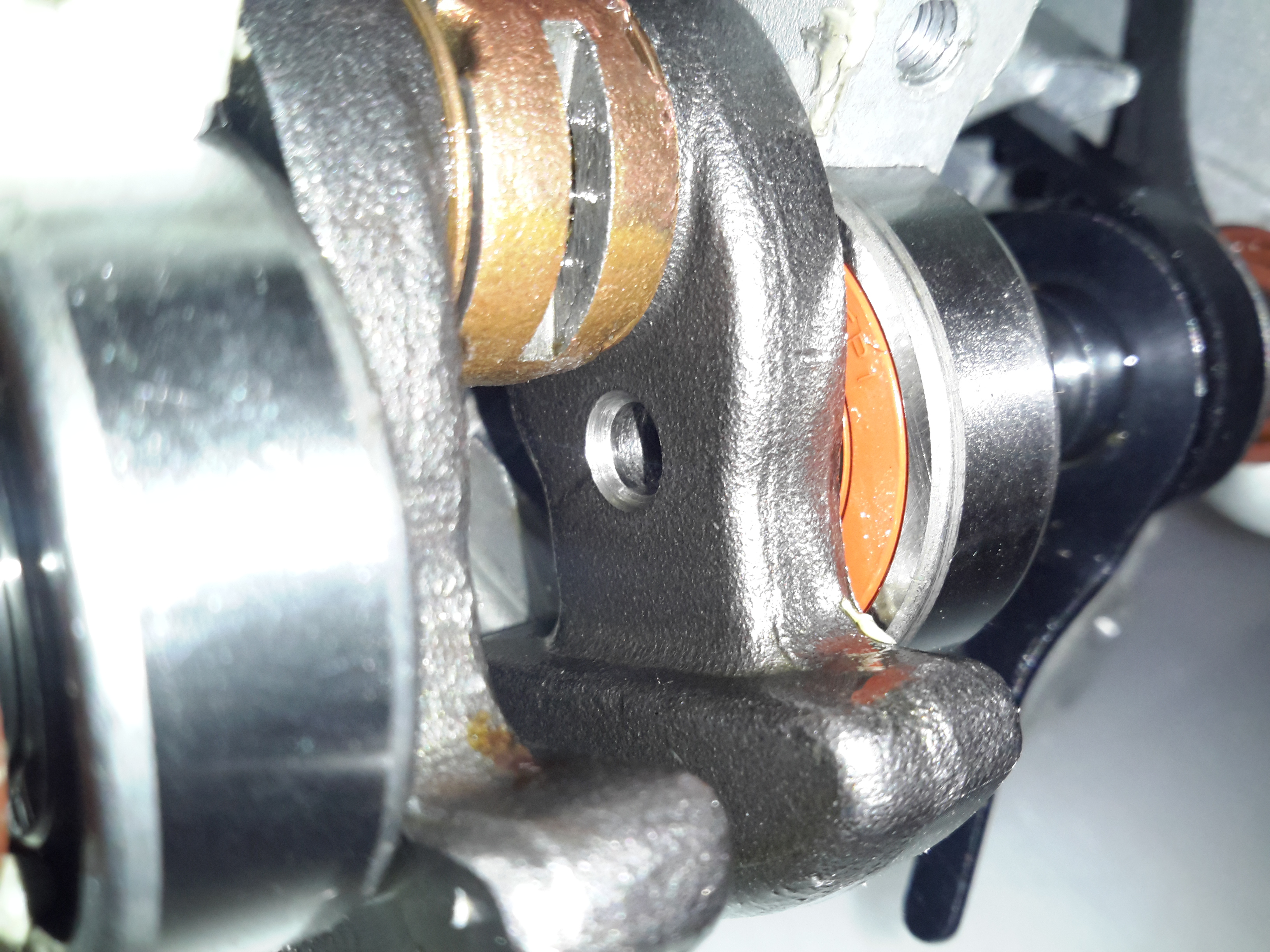
Lubrication Gallery
The oil mist feeds into the crankcase through this hollow section of shaft, there’s a drilling next to the timing belt pulley to connect the two spaces together.
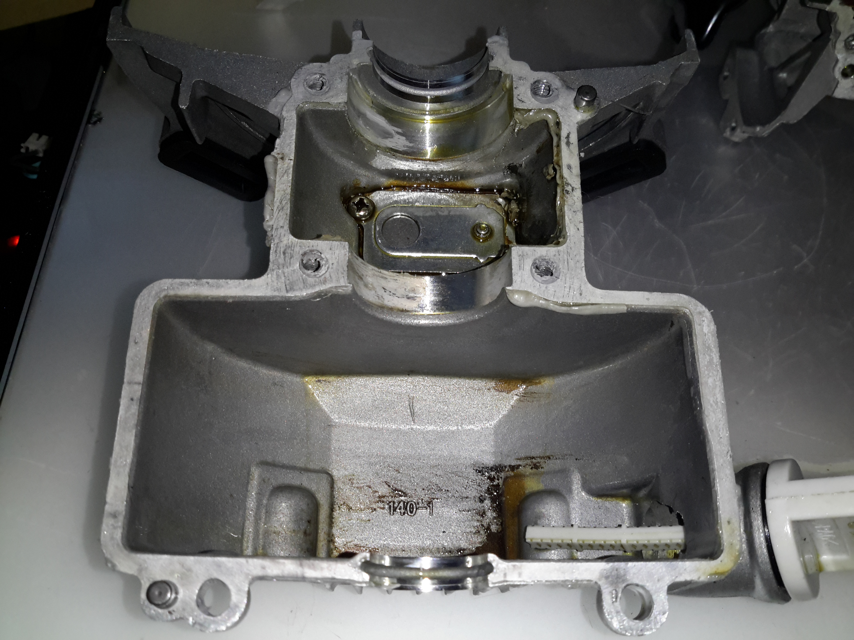
Lower Crankcase
The lower crankcase is just a simple die casting, there’s a check valve at the bottom under the crankshaft to transfer oil to the rocker cover, through the rubber tube on the outside of the engine. After the oil reaches the rocker box, it condenses & returns to the sump via the timing belt cavity.
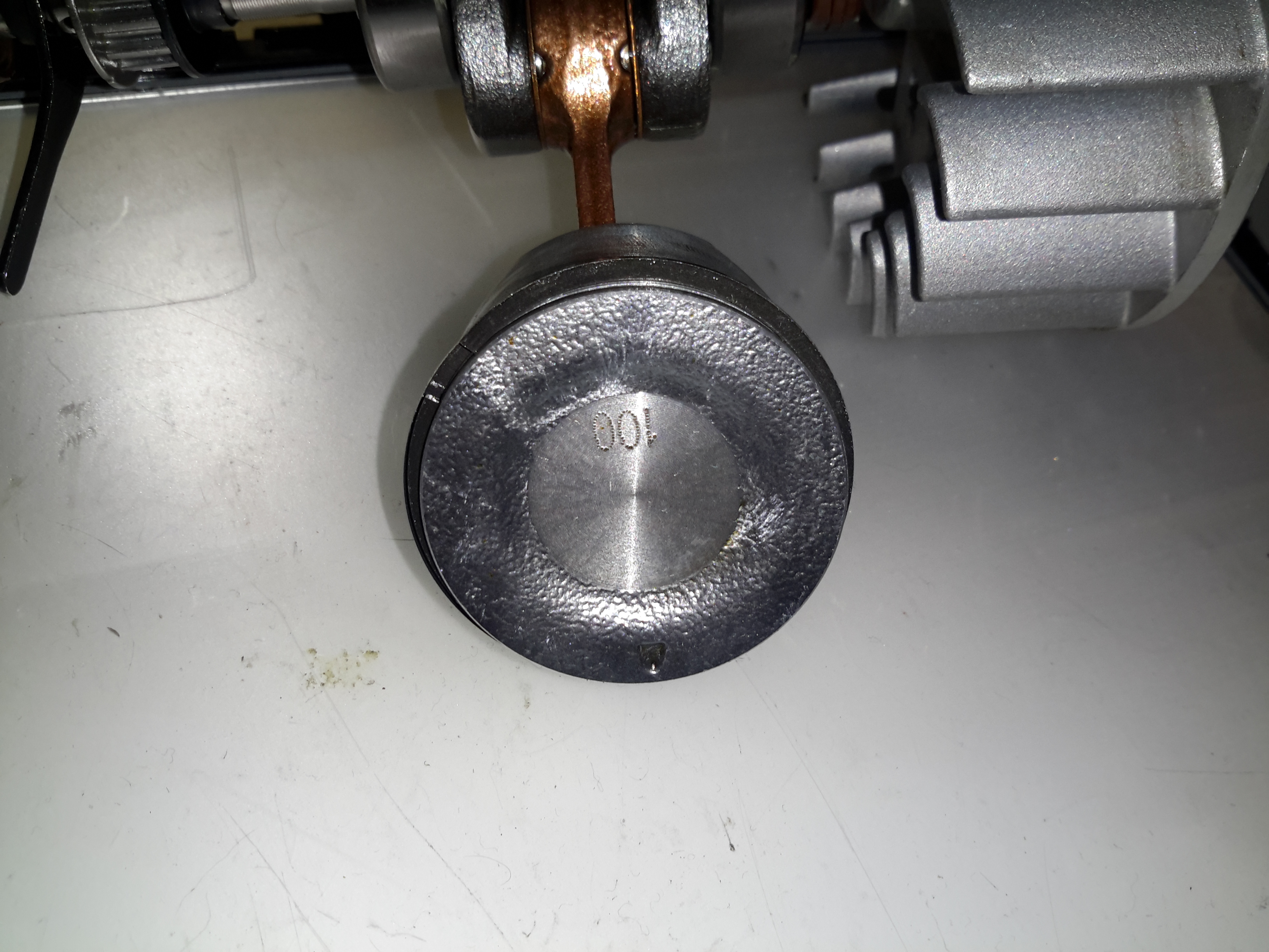
Piston Crown
Removing the crankshaft from the engine block gives me a look at the piston. The factory couldn’t even be arsed to machine the crown, it’s still got the rough finish from the hot-forging press. This bad finish will pick up much carbon from combustion, and would probably cause detonation once enough had accumulated to become incandescent in the heat of combustion. Only the centre is machined, just enough for them to stamp a number on.
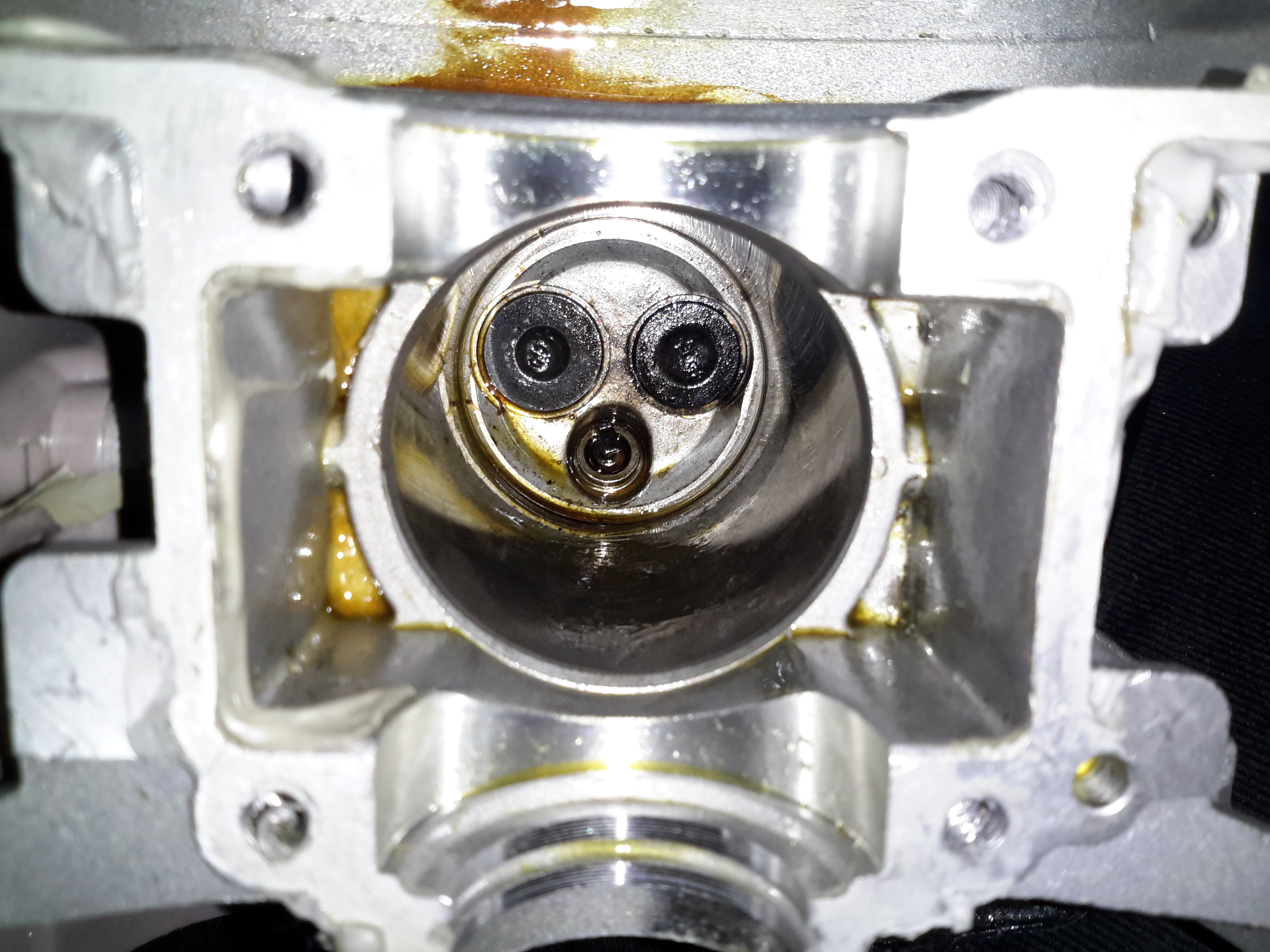
Cylinder Bore
A look up the cylinder bore shows the valves in the cylinder head. These engines, like their 2-stroke cousins have a single casting instead of a separate block & head, so getting at the valves is a little more of a pain. The cylinder bore itself is a cast-in iron liner and it’s totally smooth – like a mirror finish. There’s not a single sign of a crosshatch pattern from honing. If the first engine that died on me was the same – I’d be surprised if it wasn’t, this could easily cause ring breakage. The usual crosshatch pattern the cylinder hone produces holds oil, to better help lubricate the piston & rings. Without sufficient lubrication, the rings will overheat & expand far enough to close the end gap. Once this happens they will break.
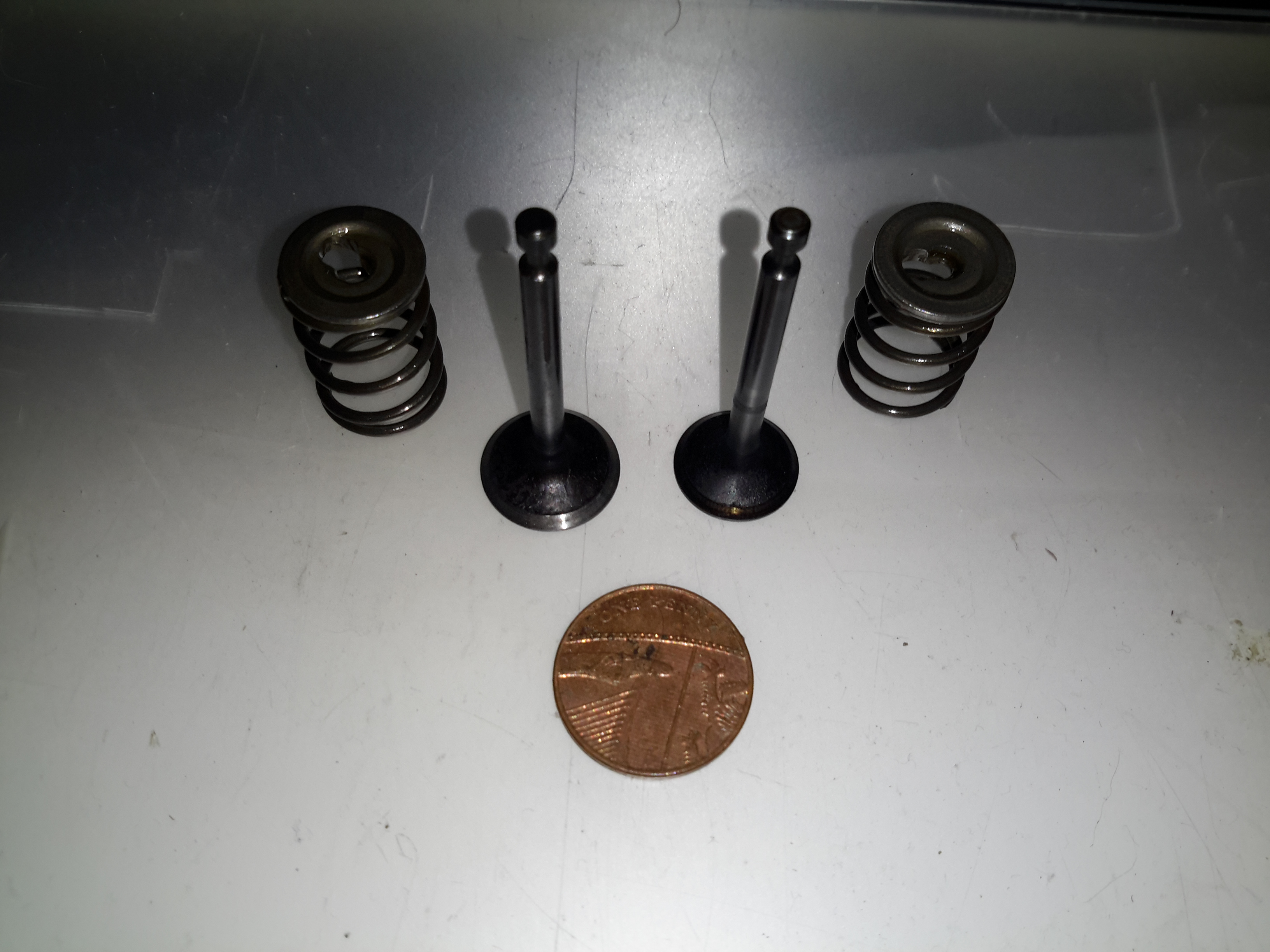
Engine Valves
Finally, here’s the valves with their springs removed from the cylinder. These are the smallest poppet valves I’ve ever seen, a British penny is provided for scale.
In all, these engines share many components with the older 2-stroke versions. The basic crankshaft & connecting rod setup is the same as I’ve seen in many old 2-strokes previous, the addition of the rather ingenious oiling system by Honda is what makes these tiny 4-strokes possible. I definitely won’t be trusting these very cheap copies in any of my projects, reliability is questionable at the least. The apparent lack of cooling air flow over the cylinder from the flywheel fan is concerning, along with the corner-cutting on the cylinder finishing process & piston crown, presumably to reduce factory costs.
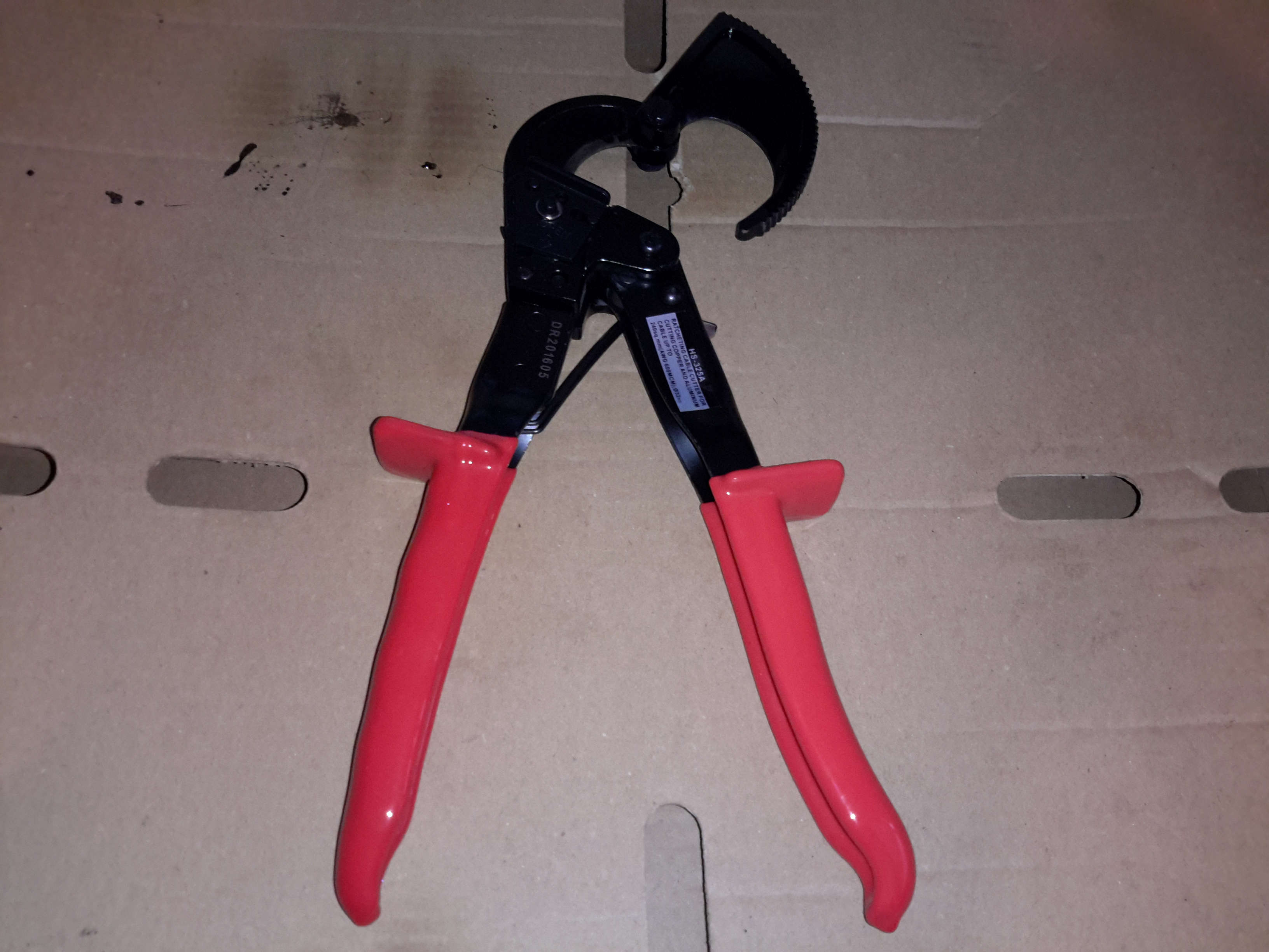
For the latest big project, replacing the battery bank on the boat with 5 brand new 200Ah Yuasa heavy duty flooded lead acids, I’m going to need to make many short links from heavy battery cable to connect all 5 batteries into a parallel bank.
Cutting cable as big in diameter as a good sized thumb is difficult at best. In the past I’ve used a hacksaw, but it doesn’t do a very clean job, especially as the cut nears the end – strands get ripped from the cable by the relatively coarse blade & this reduces the current carrying capacity.
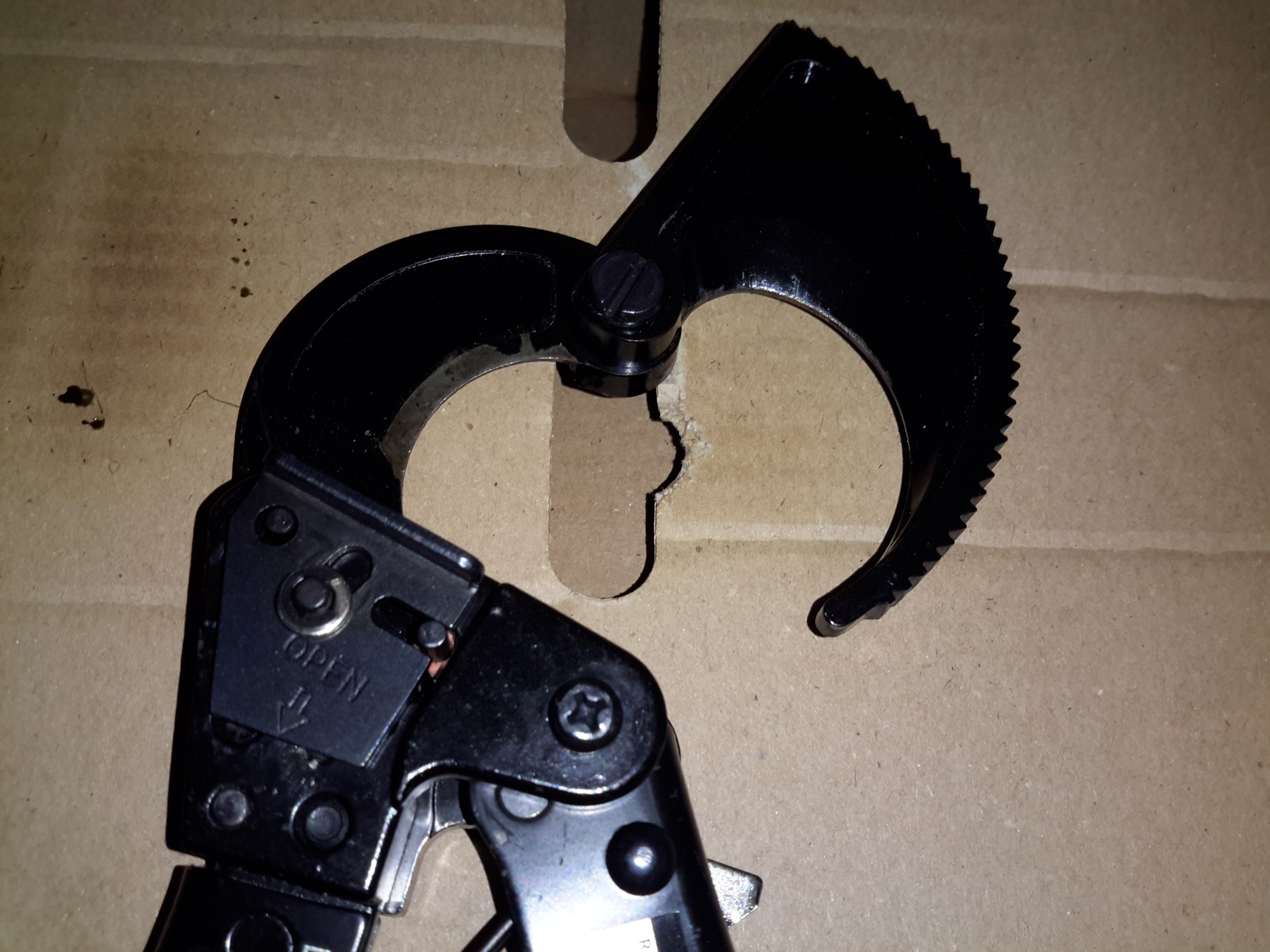
Over to eBay again netted a pair of ratchet-type heavy duty cable cutters for £30. These are rated to cut cable up to 240mm² or 600MCM.
Cutting Jaws
The cutting head on these snips is massive – cutting through cable up to 35mm in diameter takes some force. The ratchet mechanism is used to get a large mechanical advantage to force the cutters through the copper, without having to resort to more expensive & complex mechanisms such as hydraulics. (Hydraulic cable cutters do exist, but cost a small fortune & are totally over-rated for the job).
Overall the tool seems to be well made, the handles are Vinyl dipped to make them more comfortable, which certainly helps when applying a large amount of force. Running a file over the cutters themselves reveals they’re actually hardened – unusual for cheapo Chinese tools.
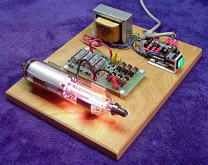
For a classroom introduction to lasers, it would be nice to have a safe setup that makes as much as possible visible to the students. Or, you may just want to have a working He-Ne laser on display in your living room! Ideally, this is an external mirror laser where all parts of the resonator as well as the power supply can be readily seen. However, realistically, finding one of these is not always that easy or inexpensive, and maintenance and adjustment of such a laser can be a pain (though that in itself IS instructive).
The next best thing is a small He-Ne laser laid bare where its sealed (internal mirror) He-Ne tube, ballast resistors, wiring, and power supply (with exposed circuit board), are mounted inside a clear Plexiglas case with all parts labelled. This would allow the discharge in the He-Ne tube to be clearly visible. The clear insulating case prevents the curious from coming in contact with the high voltage (and line voltage, if the power supply connects directly to the AC line), which could otherwise result in damage to both the person and fragile glass He-Ne tube when a reflex action results in smashing the entire laser to smithereens!
A He-Ne laser is far superior to a cheap laser pointer for several reasons:
The discharge and mirrors are clearly visible permitting the lasing process to be described in detail. Compared to this, a diode laser pointer is about as exciting as a flashlight even if you are able to extract the guts.
The beam quality in terms of coherence length, monochromaticy, shape, and stability, will likely be much higher for the He-Ne laser should you also want to use it for actual optics experiments like interferometry. (However, the first one of these – coherence length – can actually be quite good for even the some of the cheap diode lasers in laser pointers.)
For a given power level, a 632.8nm He-Ne laser will appear about 5 times brighter than a 670 nm laser pointer. 635 nm laser pointers are available but still more expensive. However, inexpensive laser pointers with wavelengths between 650 and 660 nm are becoming increasingly common and have greater relative brightness.
Important: If this see-through laser is intended for use in a classroom, check with your regulatory authority to confirm that a setup which is not explicitly CDRH approved (but with proper laser class safety stickers) will be acceptable for insurance purposes.
For safety with respect to eyeballs and vision, a low power laser – 1 mW or less – is desirable – and quite adequate for demonstration purposes.
The He-Ne laser assembly from a barcode scanner is ideal for this purpose. It is compact, low power, usually runs on low voltage DC (12 V typical), and is easily disassembled to remount in a demonstration case. The only problem is that many of these have fully potted “brick” type power supplies which are pretty boring to look at. However, some have the power supply board coated with a rubbery material which can be removed with a bit of effort (well, OK, a lot of effort!).
He-Ne Tube and Power Supply
For example, this is from a hand-held barcode scanner. A similar unit was separated into its component parts:
Melles Griot He-Ne TubeHe-Ne Laser Power Supply IC-I1
The power supply includes the ballast resistors. These could easily be mounted in a very compact case (as little as 3″ x 6″ x 1″, though spreading things out may improve visibility and reduce make cooling easier) and run from a 12v DC, 1 A wall adapter. Used barcode scanner lasers can often be found for $20 or less.
An alternative is to purchase a 0.5 to 1 mW He-Ne tube and power supply kit. This will be more expensive (figure $5 to $15 for the He-Ne tube, $25 to $50 for the power supply) but will guarantee a circuit board with all parts visible.
The He-Ne tube, power supply, ballast resistors (if separate from the power supply), and any additional components can be mounted with standoffs and/or cable ties to the plastic base. The tube can be separated from the power supply if desired to allow room for labels and such. However, keep the ballast resistors as near to the tube as practical (say, within a couple of inches, moving them if originally part of the power supply board). The resistors may get quite warm during operation so mount them on standoffs away from the plastic. Use wire with insulation rated for a minimum of 10 kV. Holes or slots should be incorporated in the side panels for ventilation – the entire affair will dissipate 5 to 10 Watts or more depending on the size of the He-Ne tube and power supply.
When attaching the He-Ne tube, avoid anything that might stress the mirror mounts. While these are quite sturdy and it is unlikely that any reasonable arrangement could result in permanent damage, even a relatively modest force may result in enough mirror misalignment to noticeably reduce output power. And, don’t forget that the mirror mounts are also the high voltage connections and need to be well insulated from each other and any human contact! The best option is probably to fasten the tube in place using Nylon cable ties, cable clamps, or something similar around the glass portion without touching the mirror mounts at all (except for the power connections).
Provide clearly marked red and black wires (or binding posts) for the low voltage DC or a line cord for AC (as appropriate for the power supply used), power switch, fuse, and power-on indicator. Label the major components and don’t forget the essential CDRH safety sticker (Class II for less than 1 mW or Class IIIa for less than 5 mW).
See:
Sam’s Demo He-Ne Laser
Above, as an example (minus the Plexiglas safety cover), contructed from the guts of a surplus Gammex laser (probably part of a patient positioning system for a CT or MRI scanner). The discrete line operated power supply is simple with the HV transformer, rectifier/doubler, filter, multiplier, and ballast resistors easily identified. This would make an ideal teaching aid.
Rather than having a see-through laser that just outputs a laser beam (how boring!), consider something that would allow access to the internal cavity, swapping of optics, and modulation of beam power. OK, perhaps the truly ultimate demo laser would use a two-Brewster tube allowing for interchangeable optics at both ends, be tunable to all the He-Ne spectral lines, and play DVD movies. 🙂 We’ll have to settle for something slightly less ambitious (at least until pigs fly). Such a unit could consist of the following components:
One-Brewster He-Ne laser tube or head. This can be something similar to the Melles Griot 05-LHB-570 tube or the Climet 9048 head which contains this tube. These have a Brewster window at one end and an internal HR mirror with a 60 cm Radius of Curvature (RoC) at the other. Their total length is about 10.5 inches (260 mm).
Adjustable mirror mount with limited range to permit easy mirror tweaking but with minimal chance of getting alignment really messed up. A basic design using a pair of plates with X and Y adjustment screws and a common pivot with lock washers for the compliance springs would be adequate.
Interchangeable mirrors of RoC = 60 cm and reflectance of 98% to 99.5% (OC) and 99.999% (HR in place of OC to maximize internal photon flux). These may be salvaged from a dead 3 to 5 mW He-Ne laser tube. Those from a tube like the Spectra-Physics 084-1 would be suitable. It would be best to install the mirrors in protective cells for ease of handling.
Baseplate to mount the laser and optics with the internal HR of the one-Brewster tube/head about 60 cm from the external mirror to create a confocal cavity – about one half of which is external and accessible. An option would be to put the external mirror mount on a movable slide to allow its position to be changed easily.
Power supply with adjustable current and modulation capability. This would provide the ability to measure output power versus current and to use the laser as an optical transmitter with a solar cell based receiver.
Plexiglas box to house and protect the laser and power supply (as well as inquisitive fingers from high voltage) with part of one side open to allow access to the internal photons.
Everything needed for such a setup is readily available or easily constructed at low cost but you’ll have to read more to find out where or how as each of the components are dealt with in detail elsewhere in Sam’s Laser FAQ (but I won’t tell you exactly where – these are all the hints you get for this one!).
A system like this could conceivably be turned into an interactive exhibit for your local science museum – assuming they care about anything beyond insects and the Internet these days. 🙂 There are some more details in the next section.
Guidelines for a Demonstraton One-Brewster He-Ne Laser
The following suggestions would be for developing a semi-interactive setup whereby visitors can safely (both for the visitor and the laser) adjust mirror alignment and possibly some other parameters of laser operation. The type of one-Brewster (1-B) He-Ne laser tube like the Melles Griot 05-LHB-570. Note that the 05-LHB-570 is a wide bore tube that runs massively multi (transverse) mode with most mirrors configurations unless an intracavity aperture is added. This is actually an advantage for several reasons:
The multi-transverse mode structure is interesting in itself and provides additional options for showing how it can be controlled.
Mirror alignment is easier and the tube will lase over a much wider range of mirror orientation.
Output power is higher for its size and power requirements.
Here are some guidelines for designing an interactive exhibit:
Mount the 1-B tube in a clear plastic (Plexiglas) enclosure with some ventilation holes to allow for cooling but make sure any parts with high voltage (anode, ballast resistors if not insulated) are safely protected from the curious. Provide a small hole lined up with the Brewster window for the intracavity beam. However, even if the B-window is at the cathode-end of the tube, don’t allow it to be accessible as the first fingerprint will prevent lasing entirely.
Put the power supply in a safe place inside another clear plastic box if desired. I’d recommend controlling it with a time switch that will turn it on for perhaps 10 minutes with a push of a button. This is a tradeoff between wear from running the laser all the time and wear from repeated starts. Don’t forget the fuse!!!
Orient the tube so the B-windows is either on the side or facing down. This will minimize dust collection and permit the rig to operate for many hours or days without the need for even dusting.
Use an output mirror with an RoC from 50 cm to planar and reflectivity of 98 to 99.5 percent at 632.8 nm. The specific parameters and distance will affect the beam size, mode structure, and output power. A shorter RoC will limit the distance over which lasing will take place but will be somewhat easier to align.
Use a decent quality mirror mount like a Newport MM-1 for the output mirror. Once it’s secured, arrange for the adjustment screws to be accessible to visitors but limit the range of rotation to less than one turn and mark the location of each screw where lasing is peaked. That way, no amount of fiddling will lose lasing entirely.
The distance between the mirror and tube can be fixed or adjustable:
For a fixed location, a distance of a few inches between the laser enclosure and mirror mount is recommended. This is enough space to install an aperture or Brewster plate. Or a hand to show that the beam is only present with the resonator is complete, not just a red light inside! But, it’s short enough that alignment is still easy.
For added excitement, put the mirror mount on a precision rail to permit the distance to be varied from 0 to at least 45 cm from the B-window. Then, it will be possible to see how the mode structure changes with distance. This will depend on the RoC of the mirror as well.
Another option is to provide various things like an iris diaphragm, thin wires and/or a cross-hair, adjustable knife edge, Brewster plate that can be oriented, etc. However, some care will be needed in making these useful without a lot of hand holding.
Weatherproofing a He-Ne Laser
If you want to use a He-Ne laser outside or where it is damp or very humid, it will likely be necessary to mount the tube and power supply inside a sealed box. Otherwise, stability problems may arise from electrical leakage or the tube may not start at all. There will then be several additional issues to consider:
Heat dissipation – For a small He-Ne tube (say 1 mW), figure this is like a 10 to 15 W bulb inside a plastic box. If you make the box large enough (e.g., 3″ x 5″ x 10″), there should be enough exterior surface area to adequately remove the waste heat.
Getting the beam out – A glass window (e.g., quality microscope slide) mounted at a slight angle (to avoid multiple reflections back to the He-Ne tube output mirror) is best. However, a Plexiglas window may be acceptable (i.e., just pointing the laser at a slight angle through the plastic case). A Brewster angle window should be used only if the He-Ne tube is a linearly polarized type (not likely for something from a barcode scanner) and then the orientation and angle must be set up for maximum light transmission.
Condensation on the optics and elsewhere – This may be a problem on exposed surfaces if they are colder than the ambient conditions. Let the entire laser assembly warm up before attempting to power it up!
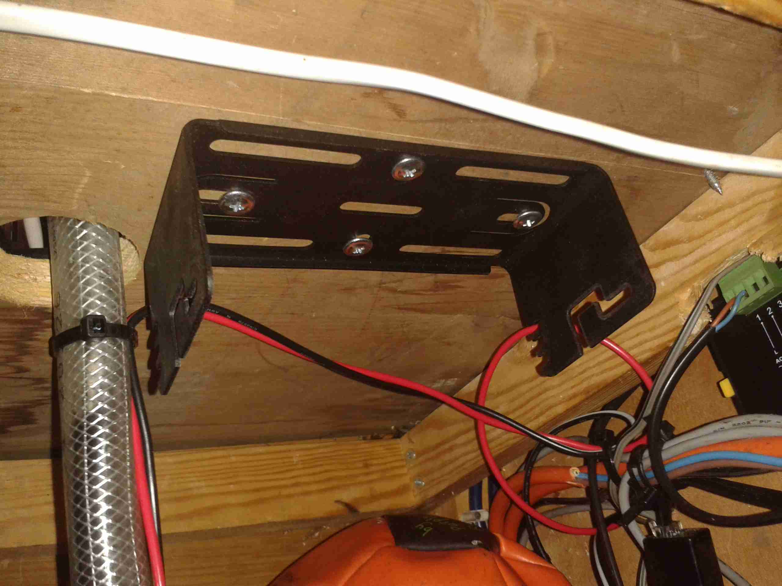
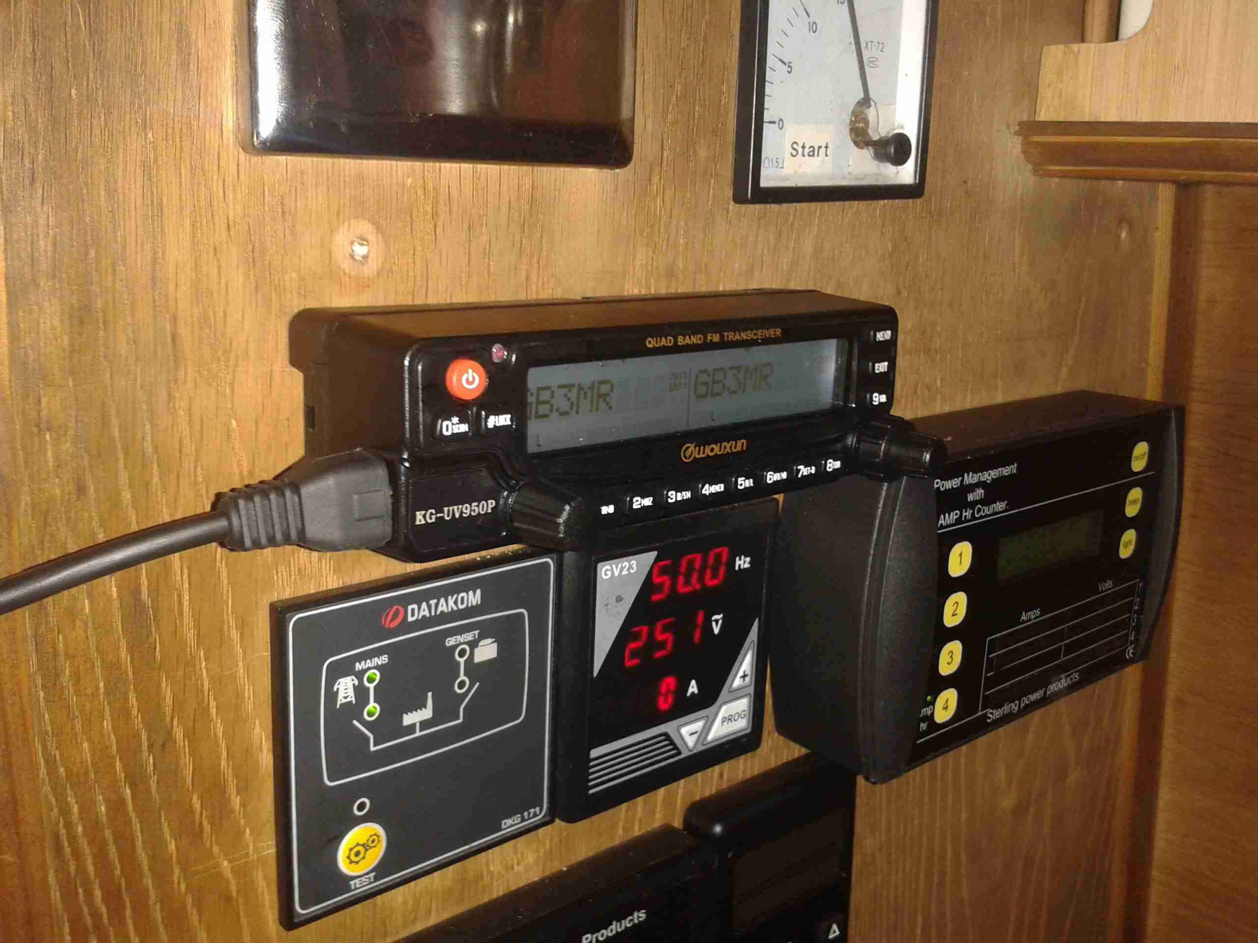
I often find myself carrying by go bag up to the boat during trips, so I can do some radio. However at 16lbs it’s a pain on public transport. A fixed radio was required! Another Wouxun GK-UV950P was ordered, and the fact that the head unit is detachable from this radio makes a clean install much easier.
Mounting Bracket
I found a nice spot under a shelf for the main radio unit, above is the mounting bracket installed.
This location is pretty much directly behind where the head unit is placed, but the audio is a bit muffled by the wooden frame of the boat & some external speakers will be required for the future.
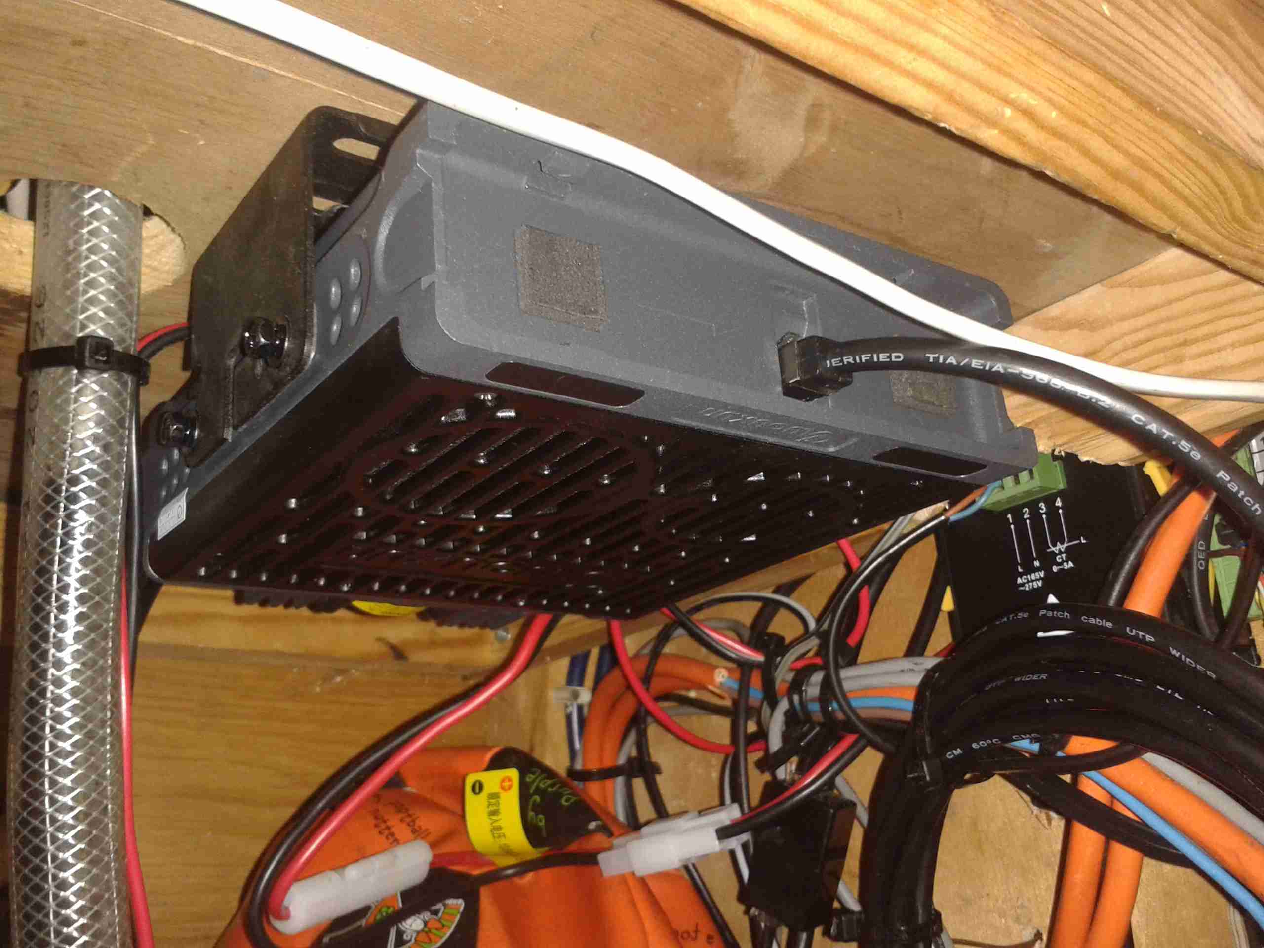
Main Radio Unit
Here’s the main radio unit mounted on it’s bracket, with the speakers facing down to improve the audio slightly. I used the supplied interface cable for the head unit, even though it’s too long. I do have the tools to swage on new RJ-45s, but the stuff is a pain to terminate nicely & I really just couldn’t be bothered. So it’s just coiled up with some ties to keep it tidy. Main power is provided directly from the main DC bus. (880Ah total battery capacity, plus 90A engine alternator, 40A solar capacity).
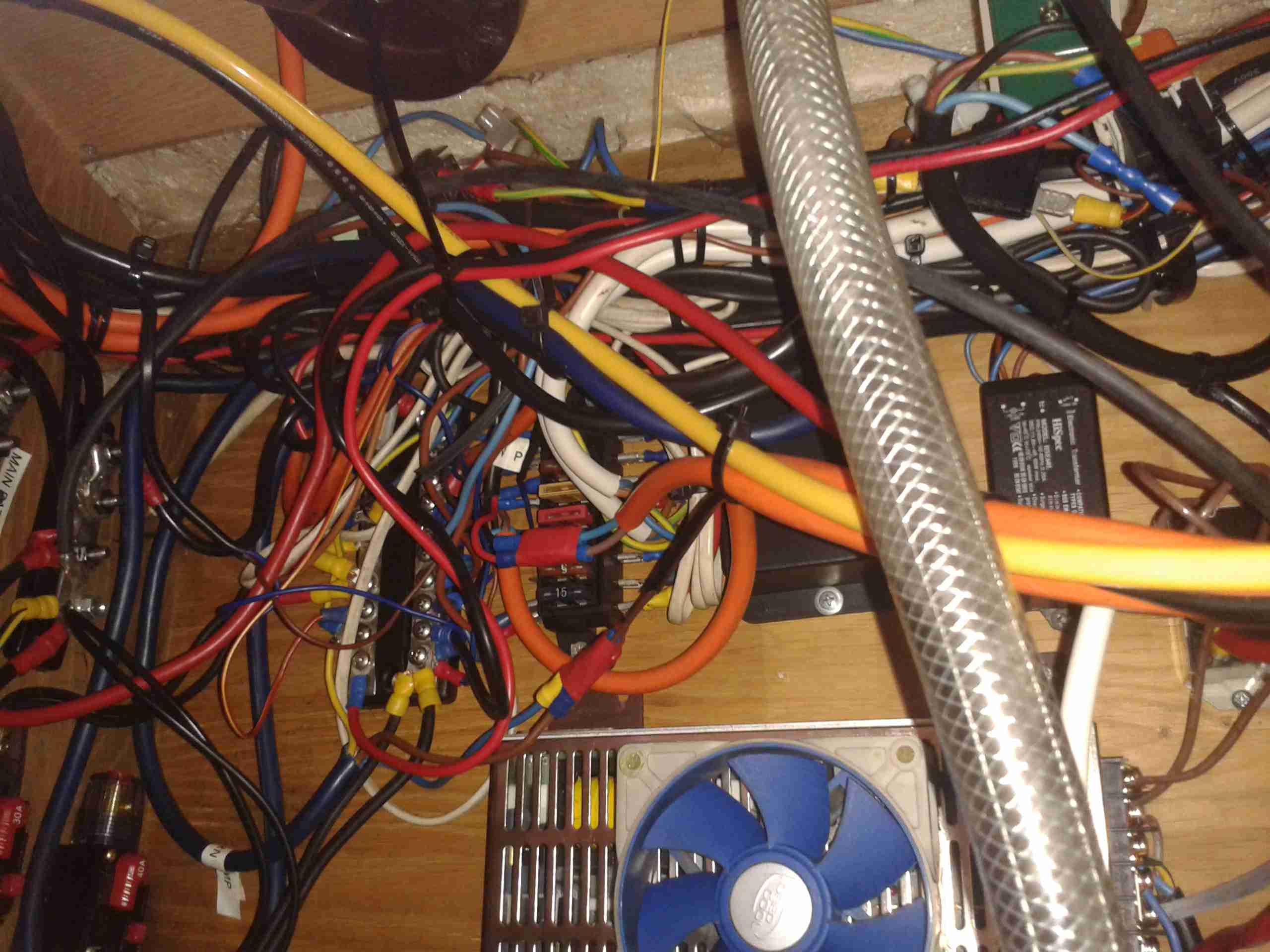
Rat’s Nest
Here’s the main DC bus, with the distribution bars. With the addition of new circuits over the years, this has become a little messy. At some point some labelling would be a good idea!
Radio Face Plate
Finally, the head unit is installed in a spot on the main panel. It does stick out a little more than I’d like, but it’s a lot of very dusty work with the router to make a nice hole to sink it further in. All my local repeaters & 2m/70cm simplex are programmed in at the moment.
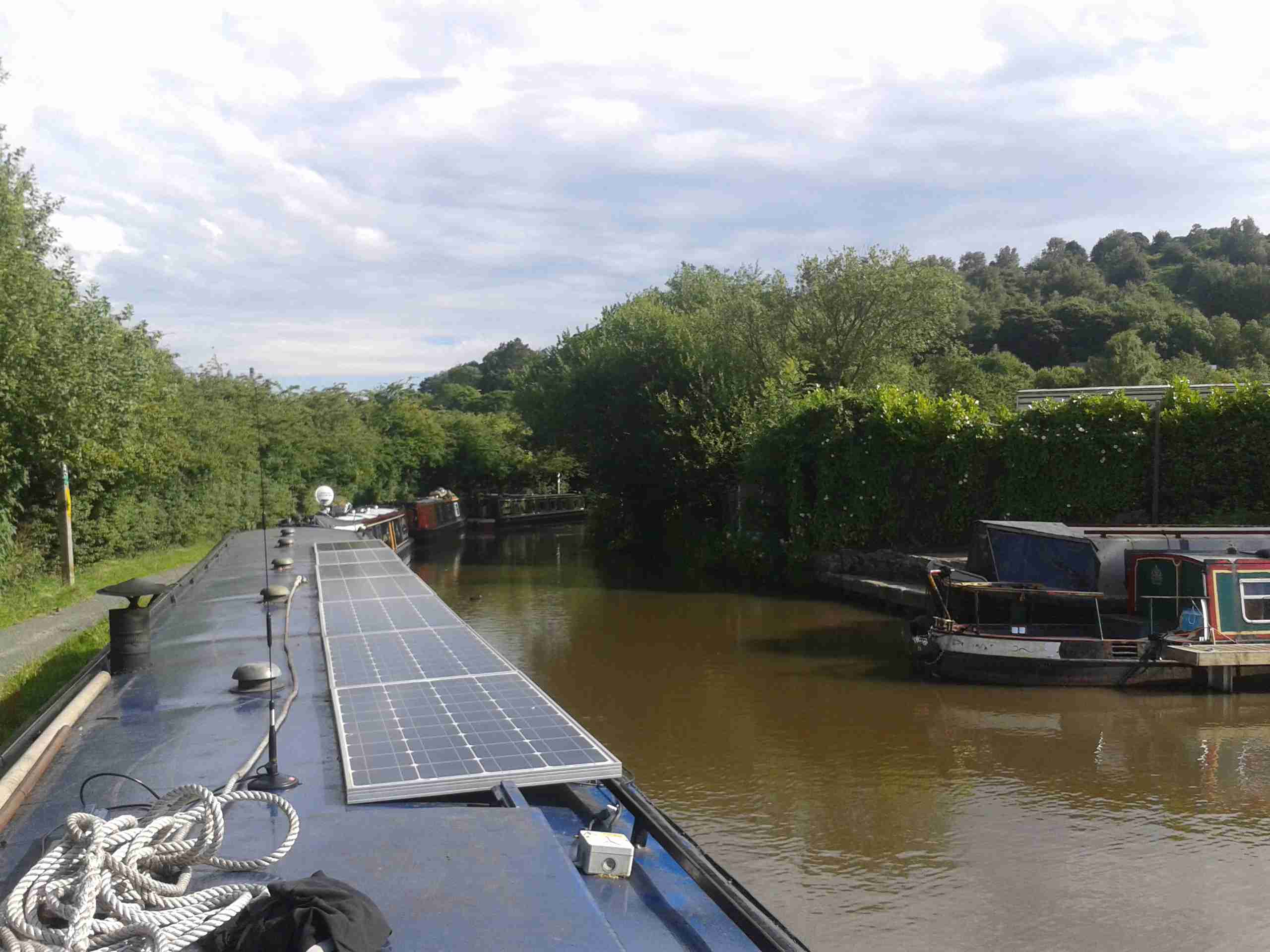
Antenna Magmount
I’ve got a Nagoya SP-80 antenna on a magmount for the radio, a magmount being used due to the many low bridges & trees on the canal. (It’s on the roof next to the first solar panel above). I prefer it to just fall over instead of having the antenna bend if anything hits it!
Part 2 will be coming soon with details of the permanent antenna feeder.
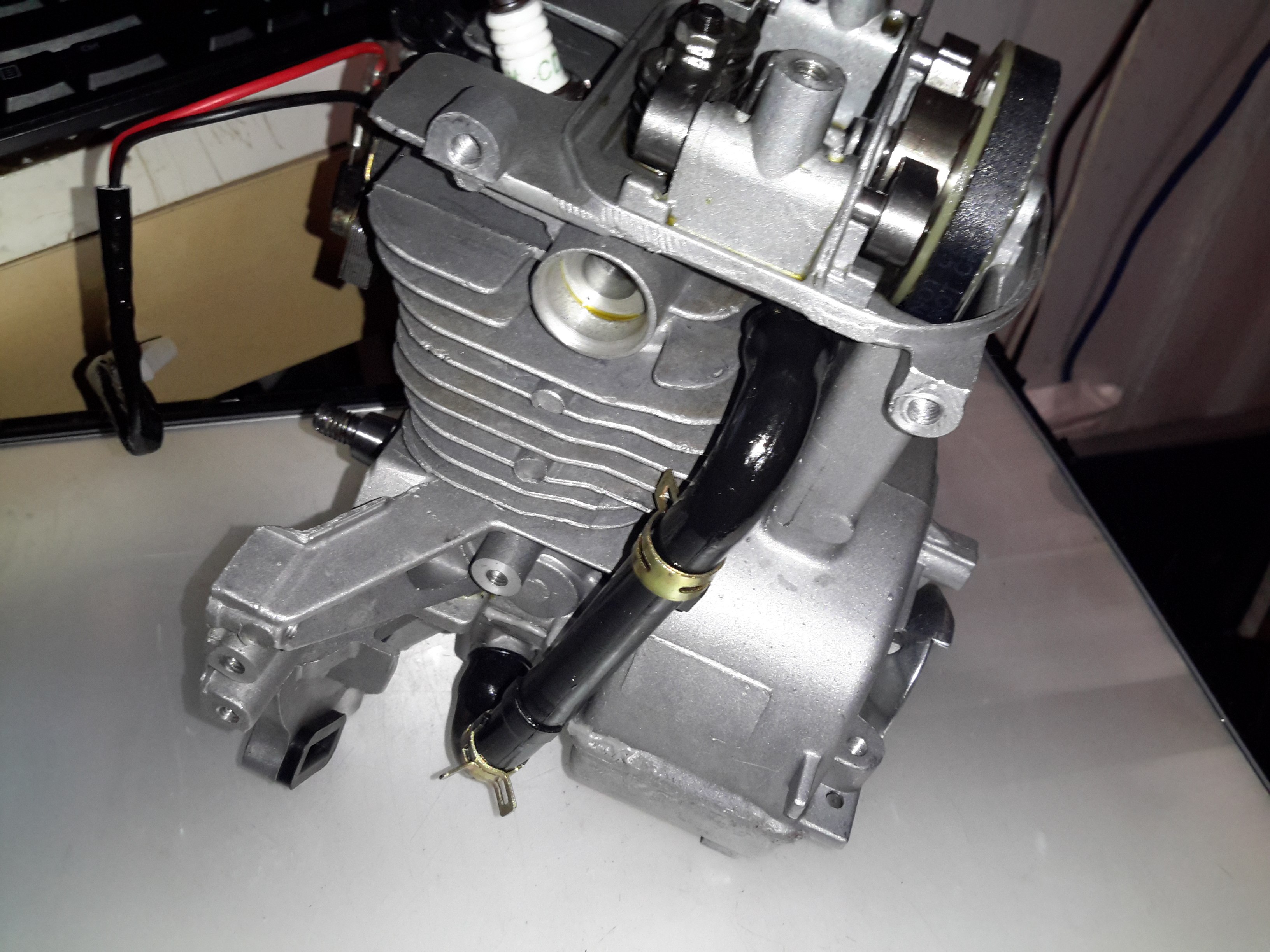
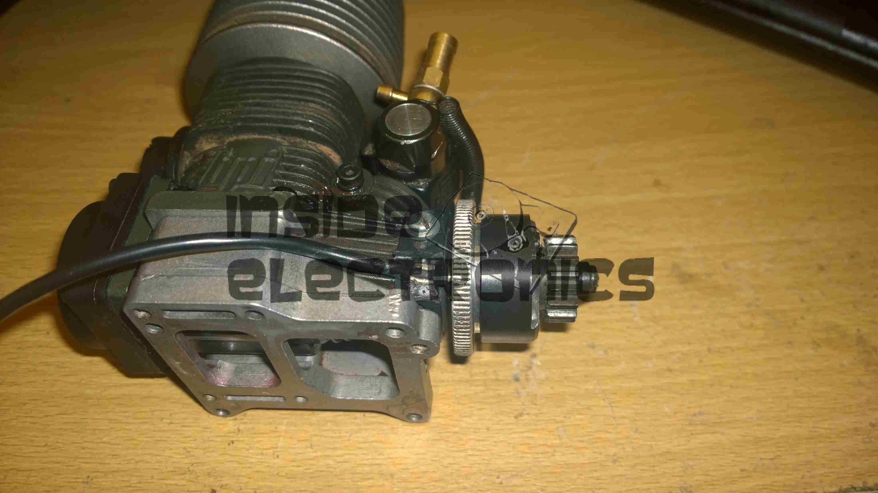
As there was no other online example of someone converting a glow/nitro car engine onto CDI ignition, I thought I would document the highlights here.
The engine is currently still running on glow fuel, but when the required fuel lines arrive I will be attempting the switch over to 2-Stroke petrol mix. This should definitely save on fuel costs.
The engine in this case is a HPI NitroStar F4.6 nitro engine, from a HPI Savage X monster truck.
F4.6 Engine
Above is the converted engine with it’s timing sensor. As The installation of this was pretty much standard, a complete strip down of the engine was required to allow the drilling & tapping of the two M3x0.5 holes to mount the sensor bracket to. The front crankshaft bearing has to be drifted out of the crankcase for this to be possible.
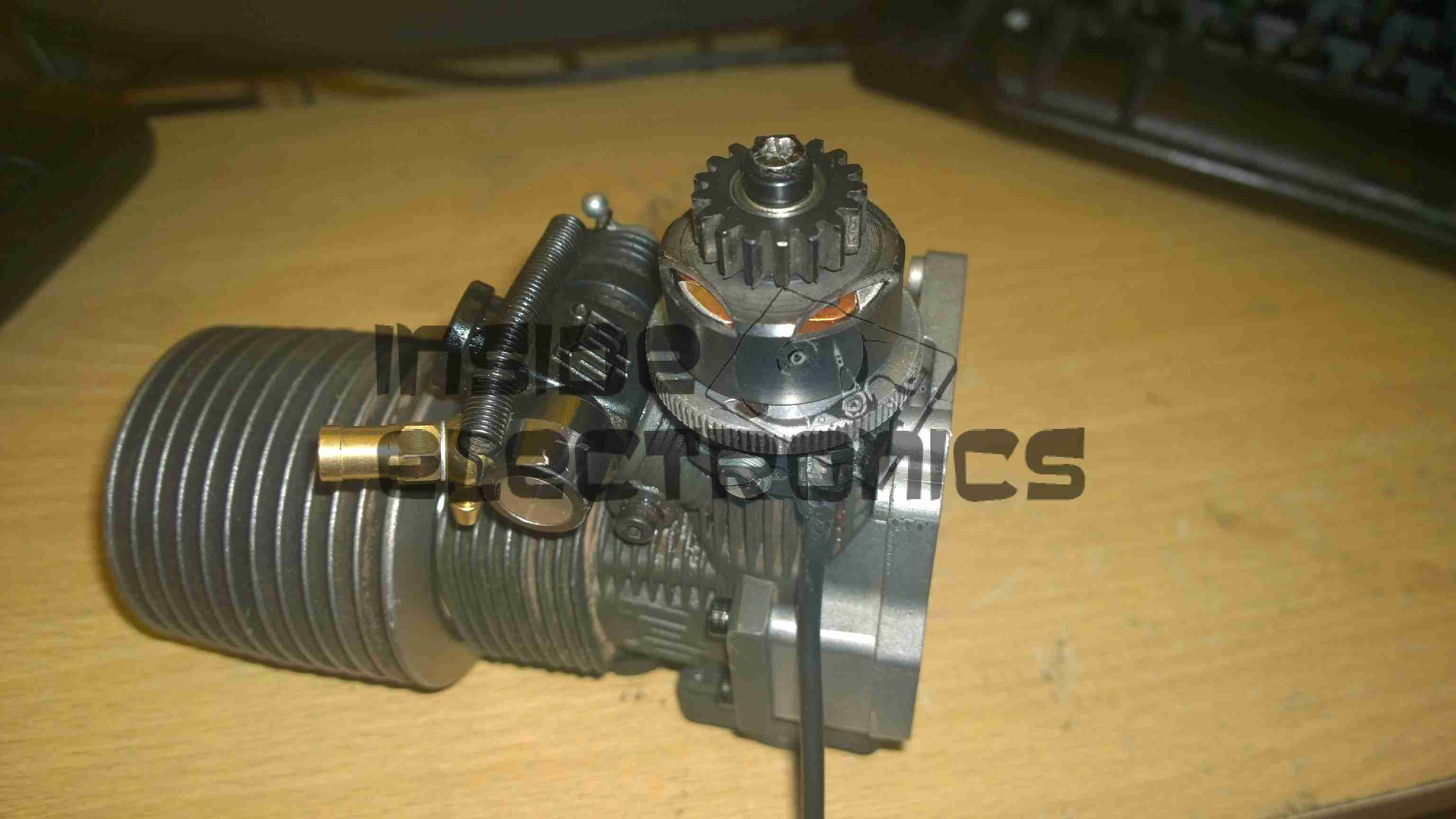
Ignition Hall Sensor
Detail of the ignition hall sensor. The bracket has to be modified to allow the sensor to face the magnet in the flywheel. Unlike on an Aero engine, where the magnet would be on the outside edge of the prop driver hub, in this case the hole was drilled in the face of the flywheel near the edge & the magnet pressed in. The Hall sensor is glued to the modified bracket with the leads bent to position the smaller face towards the back of the flywheel.
The clearance from the magnet to sensor is approx. 4mm.
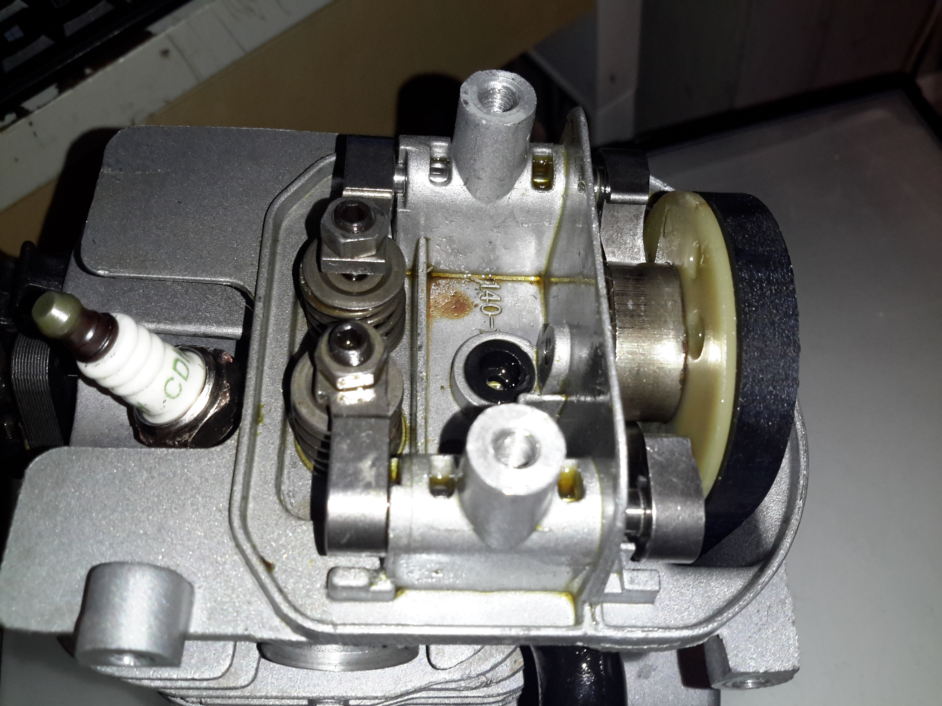
Flywheel Magnet
Detail of the magnet pressed into the flywheel. A 3.9mm hole was drilled from the back face, approx 2mm from the edge, & the magnet pressed into place with gentle taps from a mallet & drift, as I had no vice to hand.
Initial timing was a little fiddly due to the flywheel only being held on with a nut & tapered sleeve, so a timing mark can be made inside the rear of the crankcase, across the crank throw & case to mark the 28 degree BTDC point, the flywheel is then adjusted to make the ignition fire at this point, before carefully tightening the flywheel retaining nut to ensure no relative movement occurs.
The slots in the sensor bracket allow several degrees of movement to fine adjust the timing point once this rough location has been achieved.
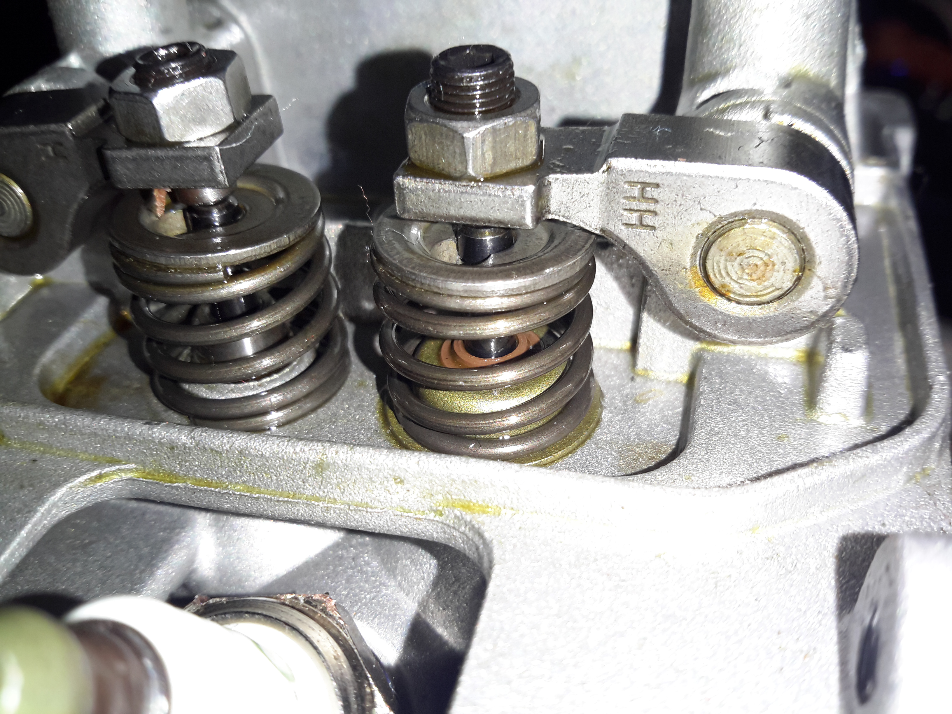
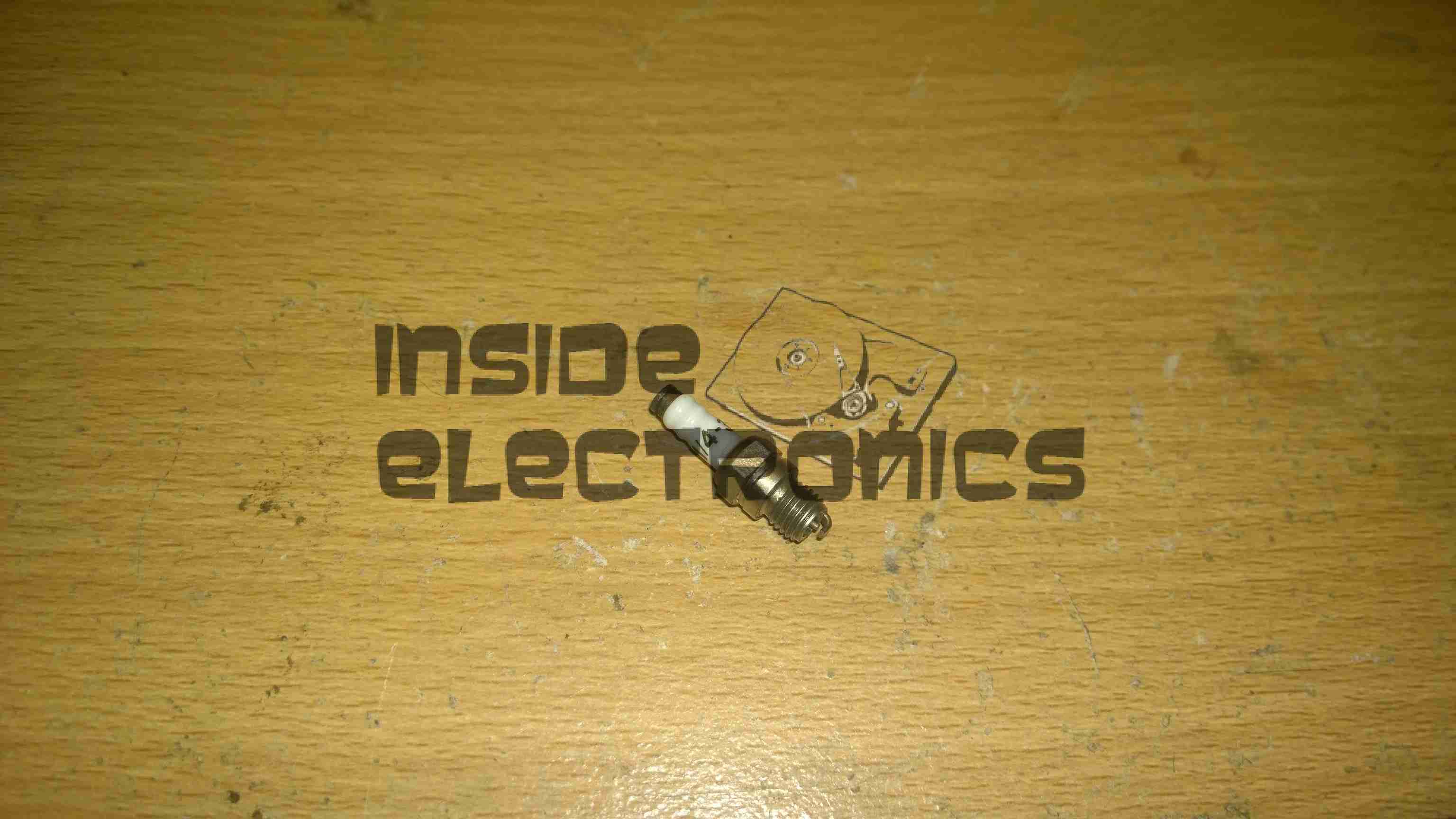
1/4″-32 Spark Plug
Definitely the tiniest spark plug I’ve ever seen, about an inch long. Some trouble may be encountered with this on some engines – the electrodes stick out about 2mm further into the combustion chamber than a standard glow plug does. This causes the ground electrode to hit the top of the piston crown. (This happens on the HPI NitroStar 3.5 engine). The addition of another copper washer under the plug before tightening should cure this problem.
RcExl CDI Ignition Module
Ignition module. Due to the depth of the plug in the heatsink head on these engines, I will have to modify the plug cap to straighten it out, as it will not fit in this configuration.
However, ignition modules are available from HobbyKing with straight plug caps, this makes modification unnecessary
The ignition & components used on this system were obtained from JustEngines.
While sourcing the main propulsion hydraulic system for nb Tanya Louise in the summer, we thought that it would be convenient to have an on board generator that didn’t require dragging off the boat & highly explosive petrol to operate.
As the hydraulics were already being fitted, we decided to add a hydraulically driven generator to solve this issue.
And this is where the problems began…
We were referred to Mike Webb of hydraulicgenerators.co.uk to supply the equipment required for this part of the project, this was to include the alternator itself, hydraulic motor to drive the alternator, the required adaptor plates to mate the motor to the generator head & a control valve block to regulate the oil flow & pressure to the motor.
After a phone call to Mike on 16-07-2013 to discuss our requirements, we settled on a system. I received the following E-Mail the next day from Mike:
Good morning, reference our conversation, Martin from BSP has given me details as to what he will be supplying, on that basis and in light of the special price I have offered, this is what I propose to supply,
1 off New 8kVa – 7kW Hydraulic driven generator 220v single phase 50hz c/w flow control valve, pressure relief valve and on/off solenoid valve, Martin did say that the engine idle is between 1000 and 1200 rpm and max speed is 3600 rpm, valves will be rated accordingly. I have the alternator and parts available now, in order for me to be able to offer this at a significantly discounted price of £ 1.200.00 nett, I will need to utilise the components I have in stock now, so I will need payment asap, delivery will be approx. 7 days, primarily due to the fact that the coupling is fabricated to suit, I can either deliver the unit to you when ready or BSP or hold onto it until everything else is in place. The alternator is a Meccalte S20W that I bought for another customer a few weeks ago, but he cancelled and I don’t have, at this time, anyone else interested in it, so either I do a deal with you at the above price or wait until someone else comes along and wants the unit.
With regards to installation, let me know if you need any help, but it would be best to install when the engine is being installed and the rest of the system hosed up, I assume BSP will be sorting this, in which case I’ll liase with Martin.
I trust that this meets with your approval and look forward to hearing from you.
At this point an order was placed with Mike, & the money transferred so he could begin building the unit for us. As can be seen from the E-Mail, a lead time of 7 days was stated.
After a few phone calls over the following month, firstly being told that the custom parts to mate the generator to the motor had not come back from the engineers, I sent another E-Mail to Mike on 10-09-2013, and got no reply.
Following another phone call, I was told that the generator had been shipped, however Mike would not give me any tracking details for the shipment, and would not initially tell me who it was shipped with.
Again the generator didn’t turn up.
More phone calls ensued & I was told at this point that the shipping company had been confused by the address given, shipped back to Mike. At this point I was informed that the shipping company had actually LOST it. Several more phone calls later I was promised that a replacement generator would now ship no later than 08-10-2013. A follow up E-Mail two days later also generated no reply.
At this point I was beginning to wonder if I would ever see the goods we had paid for, but finally a shipment arrived from Mike
~15-10-2013, over TWO MONTHSafter our promised delivery date. However, even having been delivered, all was not well with the goods.
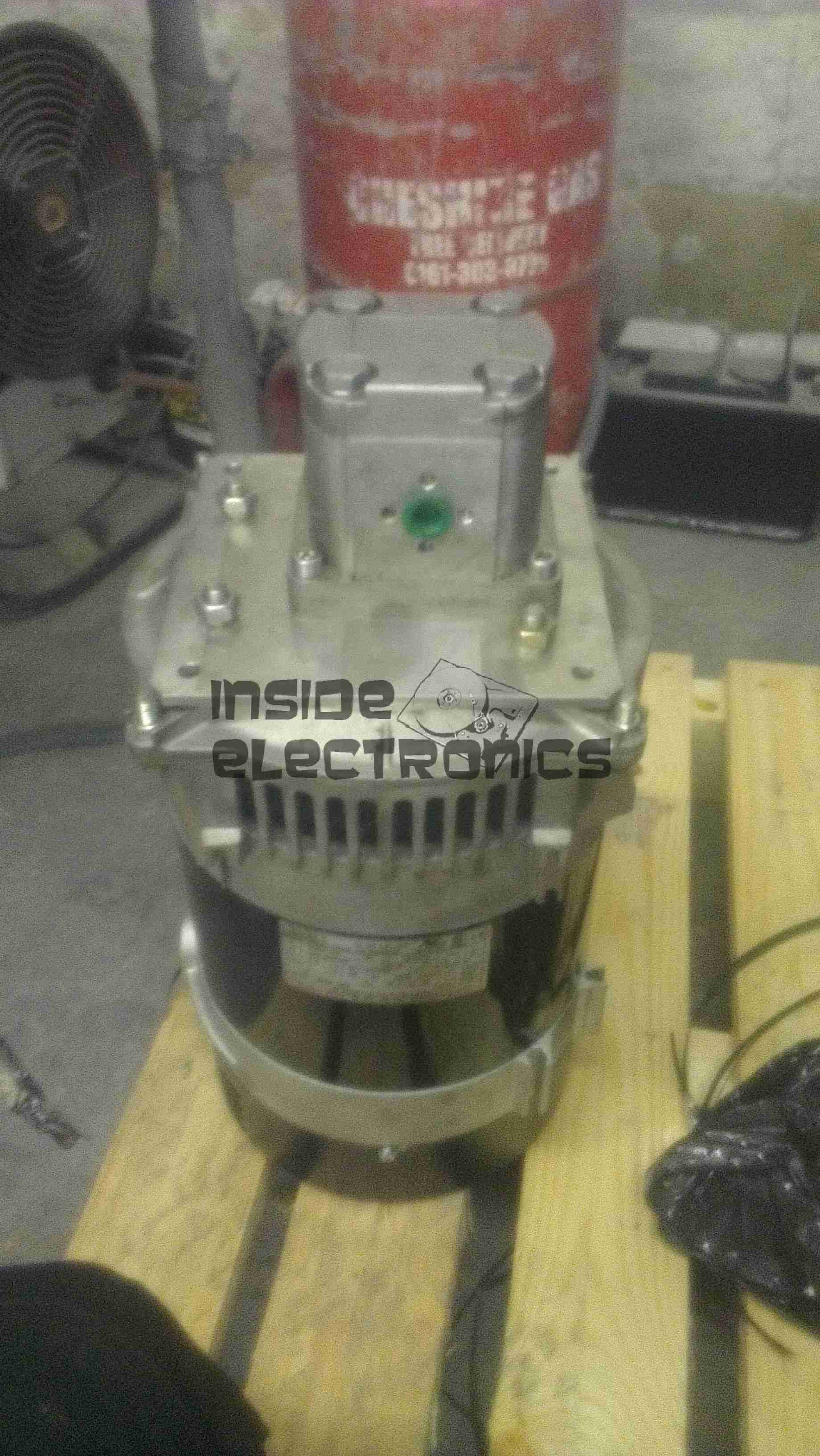
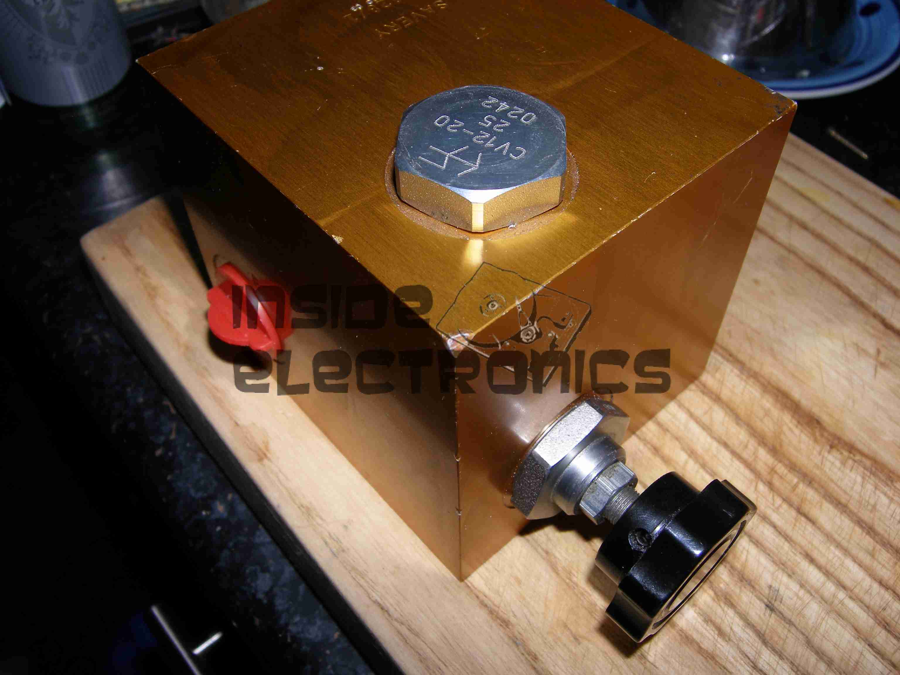
Generator Pallet
Above is the generator supplied. No mounting bracket, no integrated valve block, in short, nothing like what was described in Mike’s documentation & website. The original documentation is available here for reference: [download id=”5564″]
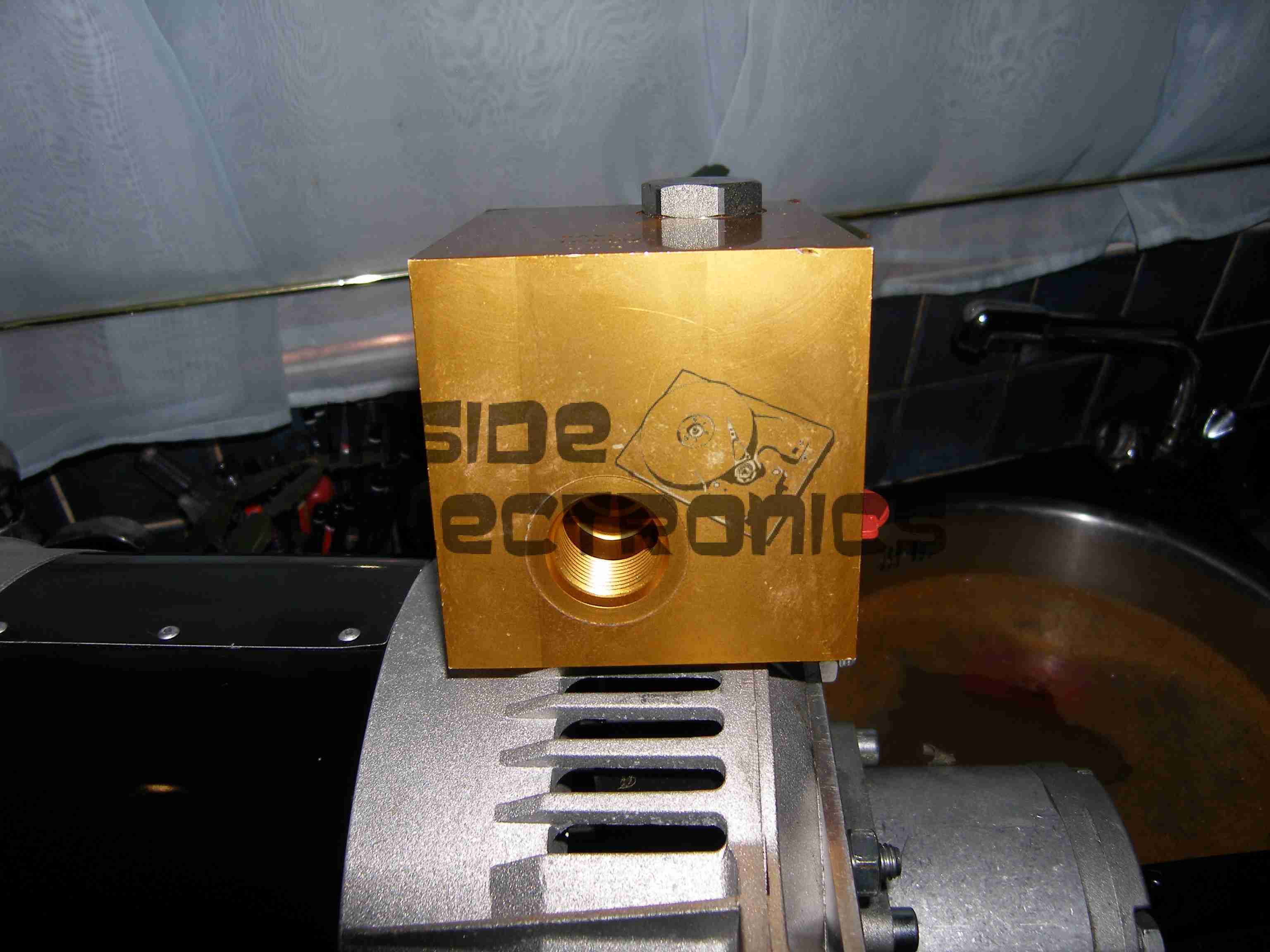
As can be seen, there is an open port on the side of the valve block. This is where the ON/OFF control solenoid valve is supposed to be located.
After several more unanswered E-Mails & phone calls, I had to get somewhat more forceful in my messages, as now Mike had begun outright lying about what was specified in the original order. In which that there was no solenoid valve required. So the following E-Mail was sent 21-10-2013:
Mike,
Having had a conversation with Martin, about him attempting to contact you regarding what you have supplied to us, I need this resolving ASAP now, as I am being held up by the fact that there is an open port on your valve block where the solenoid control valve is supposed to be located.
As it stands the valve block & therefore the generator you have supplied to us is useless for it’s intended purpose & I will be seeking legal advice on this matter if a resolution cannot be made this week, considering you have not replied to any E-Mail I have sent since the unit’s massively delayed arrived.
In your original correspondence it is certainly indicated that this valve was to be fitted, which was also Martin’s instruction to you.
I await your expedient response.
This threat of legal action actually spurred a response from Mike, who finally replied with the following on 25-10-2013:
Ben,
Sorry about all this, I have been away and down with a bug for the last week, I will sort this today and will have the required parts shipped to you on Monday for Tuesday delivery.
Regards
Mike
Another promise of a delivery date, so I waited a little longer, until the Friday of that week. Still no delivery. No surprise there then.
(I didn’t believe the story about illness either).
At this point I again attempted contact, but got nowhere, even with legal threats. So I’ve given up completely on this & been forced to source the parts elsewhere at extra cost.
This company is not the one to go to if you require a hydraulic generator unit for any application, as you’d be lucky to get any part of what you order on time, if at all.
Operations are run by an all out liar who seems to be happy to accept money but not ship the goods that had been paid for.
Mike having explained to me that the shipping company had lost a generator, and he would have to build me another one to replace it also does not make sense, as in the initial phone call & mail he stated that the Meccalte generator that we eventually received was a single unit that was specially ordered for another client, and the factory build date on the unit certainly gave away the fact that the generator head had been sat around for some considerable time before I came along & made a purchase.
Hopefully this post will get a high Google ranking, to ensure that anyone else who happens to be looking for a similar piece of equipment does not have the misfortune to trust this man.
We were referred to him on good faith & unfortunately in this case it did not go well.
This is a late 90’s business timeclock, used for maintaining records of staff working times, by printing the time when used on a sheet of card.
Front Internal
Here is the top cover removed, which is normally locked in place to stop tampering. The unit is programmed with the 3 buttons & the row of DIP switches along the top edge.
Instructions
Closeup of the settings panel, with all the various DIP switch options.
CPU & Display
Cover plate removed from the top, showing the LCD & CPU board, the backup battery normally fits behind this. The CPU is a 4-bit microcontroller from NEC, with built in LCD driver.
PSU & Drivers
Power Supply & prinhead drivers. This board is fitted with several NPN Darlington transistor arrays for driving the dox matrix printhead.
Printhead
Printhead assembly itself. The print ribbon fits over the top of the head & over the pins at the bottom. The drive hammers & solenoids are housed in the circular top of the unit.
Printhead Bottom
Bottom of the print head showing the row of impact pins used to create the printout.
Bottom of the solenoid assembly with the ribbon cable for power. There are 9 solenoids, to operate the 9 pins in the head.
Return Spring
Top layer of the printhead assembly, showing the leaf spring used to hold the hammers in the correct positions.
Hammers
Hammer assembly. The fingers on the ends of the arms push on the pins to strike through the ribbon onto the card.
Solenoids
The ring of solenoids at the centre of the assembly. These are driven with 3A darlington power arrays on the PSU board.
Gearbox Internals
There is only a single drive motor in the entire unit, that both clamps the card for printing & moves the printhead laterally across the card. Through a rack & pinion this also advances the ribbon with each print.
Here is an old chemical dosing system for industrial washing machines. These units are 4-pump models, with dual pumpheads. The motors are reversed to operate alternate pumps in the same head.
Label
From 2006, this is a fairly old unit, and made in the UK.
CPU Board
Main controller PCB, with interface to the power electronics via the ribbon cable, an external serial port for programming to it’s left. Powered by an ST microcontroller. The LCD is below this board.
PCU & Driver PCBs
Main power supply, sense input & motor driver boards. The PSU outputs +5v, +12v & +24v. The inputs on the lower left connect to the washing machine & trigger the pumps via the programming on the CPU. The motors are driven by L6202 H-Bridge drivers from ST.
Motor Assembly
Motor & gearbox assembly on the back of the pumphead. These are 24v DC units with 80RPM gearboxes.
UPDATE:
As it seems to be difficult to find, here is the user manual for this unit:
[download id=”5557″]
This is the teardown of a Zebra P330i plastic card printer, used for creating ID cards, membership cards, employee cards, etc. I got this as a faulty unit, which I will detail later on.
This printer supports printing on plastic cards from 1-30mils thick, using dye sublimation & thermal transfer type printing methods. Interfaces supplied are USB & Ethernet. The unit also has the capability to be fitted with a mag stripe encoder & a smart card encoder, for extra cost.
Print Engine
On the left here is the print engine open, the blue cartridge on the right is a cleaning unit, using an adhesive roller to remove any dirt from the incoming card stock.
This is extremely important on a dye sublimation based printing engine as any dirt on the cards will cause printing problems.
Cards In Feeder
Here on the right is the card feeder unit, stocked with cards. This can take up to 100 cards from the factory.
The blue lever on the left is used to set the card thickness being used, to prevent misfeeds. There is a rubber gate in the intake port of the printer which is moved by this lever to stop any more than a single card from being fed into the print engine at any one time.
Card Feeder Belt
Here is the empty card feeder, showing the rubber conveyor belt. This unit was in fact the problem with the printer, the drive belt from the DC motor under this unit was stripped, preventing the cards from feeding into the printer.
Print Head
Here is a closeup of the print head assembly. The brown/black stripe along the edge is the row of thin-film heating elements. This is a 300DPI head.
Print Station
This is under the print head, the black roller on the left is the platen roller, which supports the card during printing. The spool in the center of the picture is the supply spool for the dye ribbon.
In the front of the black bar in the bottom center, is a two-colour sensor, used to locate the ribbon at the start of the Yellow panel to begin printing.
LCD PCB
Inside the top cover is the indicator LCD, the back of which is pictured right.
This is a 16×1 character LCD from Hantronix. This unit has a parallel interface.
LCD
Front of the LCD, this is white characters on a blue background.
Roller Drive Belts
Here is the cover removed from the printer, showing the drive belts powering the drive rollers. There is an identical arrangement on the other side of the print engine running the other rollers at the input side of the engine.
Mains Filter
Here the back panel has been removed from the entire print engine, complete with the mains input wiring & RFI filtering.
This unit has excellent build quality, just what is to be expected from a £1,200+ piece of industrial equipment.
Main Frame With Motors
The bottom of the print engine, with all the main wiring & PCB removed, showing the main drive motors. The left hand geared motor operates the head lift, the centre motor is a stepper, which operates the main transmission for the cards. The right motor drives the ribbon take up spindle through an O-Ring belt.
Feeder Drive Motor
Card feeder drive motor, this connects to the belt assembly through a timing belt identical to the roller drive system.
All these DC geared motors are 18v DC, of varying torque ratings.
Power Supply
Here is the main power supply, a universal input switch-mode unit, outputting 24v DC at 3.3A.
PSU Label
PSU info. This is obviously an off the shelf unit, manufactured by Hitek. Model number FUEA240.
Print Engine Rear
The PSU has been removed from the back of the print engine, here is shown the remaining mechanical systems of the printer.
Print Engine Components
A further closeup of the print engine mechanical bay, the main stepper motor is bottom centre, driving the brass flywheel through another timing belt drive. The O-Ring drive on the right is for the ribbon take up reel, with the final motor driving the plastic cam on the left to raise/lower the print head assembly.
The brass disc at the top is connected through a friction clutch to the ribbon supply reel, which provides tension to keep it taut. The slots in the disc are to sense the speed of the ribbon during printing, which allows the printer to tell if there is no ribbon present or if it has broken.
RFID PCB
Here is a further closeup, showing the RFID PCB behind the main transmission. This allows the printer to identify the ribbon fitted as a colour or monochrome.
The antenna is under the brass interrupter disc on the left.
I/O Daughterboard
The I/O daughterboard connects to the main CPU board & interfaces all the motors & sensors in the printer.
Main PCB
Here is the main CPU board, which contains all the logic & processing power in the printer.
CPU
Main CPU. This is a Freescale Semiconductor part, model number MCF5206FT33A, a ColdFire based 32-bit CPU. Also the system ROM & RAM can be seen on the right hand side of this picture.
Ethernet Interface
Bottom of the Ethernet interface card, this clearly has it’s own RAM, ROM & FPGA. This is due to this component being a full Parallel interface print server.
Ethernet Interface Top
Top of the PCB, showing the main processor of the print server. This has a ferrite sheet glued to the top, for interference protection.
This unit was bought from eBay to experiment with Magnetic Stripe cards, for little money. This unit is capable of reading & writing all 3 tracks, & both Hi-Co & Lo-Co card types.
Interfaced to a PC through USB, this has a built in PL2303 USB-Serial IC & requires 3A at 9v DC to operate.
The 3 Indicator LEDs on the top of the unit can be toggled by the included software for Power/OK/Fault condition signalling.
Unit Bottom
Bottom of the unit with the model labels.
Model Label
Closeup of the model label & serial number.
PCB Bottom
Here the bottom cover has been removed, showing the main PCB. The pair of large ICs bottom center interface with the magnetic heads. The IC above them has had the markings sanded off.
USB-Serial Interface
Closeup of the Prolific PL-2303 USB-Serial converter IC.
PCB Top
Here the connections to the R/W heads are visible, current limiting resistors at the left for the write head, a pair of signal relays, a pair of optoisolators & a LM7805 linear voltage regulator.
LEDs
Here is the trio of indicator LEDs on a small sub-board.
Frame Bottom
The PCB has been removed from the main frame here, the only component visible is the rotary encoder.
Rotary Encoder
The rotary encoder has a rubber wheel fitted, which reads the speed of the card as it is being swiped for writing. This allows the control logic to write the data to the stripe at the correct rate for the speed of the card. This allows the unit to write cards from 5-50 inches per second speed.
The Write head is directly behind the rubber pressure roller.
Read/Write Heads
Here you can see the R/W head assembly. The write head is on the right, read on the left. When a card is written to, it immediately gets read by the second head for verification.
A bit of a shift from my usual content, but I thought this deserved a place for people to see. Only relevant for people of the UK though.
“I’m a DWP worker sticking his head above the parapet and hoping not to get shot…
I work in a busy Jobcentre and my customers are those 25+ who’ve been out of work for 13 weeks or longer. Probably 60-70% of the one hundred or more people I see every week [who] are evidently not fit for work and yet, in theory, it’s my job to whip them through the same hoops as everybody else, persecute them, attempt to stop their benefits and generally shame them into applying for all manner of wholly unsuitable jobs that they’re never going to be able to do.
In reality, what I do is tell them the system sucks and advise them of ways they can stay beneath the radar, or suggest they sign off JSA and move onto ESA and do whatever I can to make the transition as trouble free as possible.
On the other side of the office to me are the Pathways team, who deal with customers on ESA. We all know that over the coming months most of them will be forced to migrate over to the JSA bods like myself and we won’t be able to cope with either the numbers or the particular problems that this customer group represents.
The point of all this waffle is that the policy makers have embarked upon their catastrophic journey without consulting the frontline workers who, without exception in my experience, KNOW that the planned changes CANNOT work.
I would advise people worried about a forced transition from ESA to JSA to be brave and try not to lose too much sleep about it… It’s just not do-able in the real world, there’ll be a horrible mess and people’s lives will face some awful but shortlived disruption and then it’ll be business as usual.
Also, for those who face the indignity of having to venture into a jobcentre from time to time, please be assured – the majority of those who work in them are actually on your side, and have probably less faith in our political masters than you do, and just as much awareness as yourselves that all their vitriolic guff about benefit scroungers and feckless layabouts is simply empty, venomous scapegoating…”
Please feel free to copy and paste this to your own notes/blog, etc. Spread the truth.
Here is a label maker, bought on offer at Maplin Electronics. Full Qwerty keyboard with 1 line dot matrix LCD display visible here. Power is 4 AAA cells or a 6v DC Adaptor.
Rear
Rear cover removed. Battery compartment is on the left hand side, space for the tape cartridge on the right. Ribbon cable leading to the thermal print head is on the far right, with rubber tape drive roller.
PCB
PCB under the top cover with the main CPU, a MN101C77CBM from Panasonic. This CPU features 48K Mask ROM & 3K of RAM. Max clock frequency is 20MHz. 32kHz clock crystal visible underneath a Rohm BA6220 Electronic speed controller IC.
This is used to drive the printer motor at a constant accurate speed, to feed the tape past the thermal head. Miniature potentiometer adjusts speed.
Ribbon cable at the bottom of the board connects to the print head, various wiring at the left connects to the battery & DC Jack.
Printer Drive
Printer drive mechanism. Small DC motor drives the pinch roller though a gear train. DC Jack & reverse polarity protection diode is on the right.
This unit uses a centre negative DC jack, which is unusual.
Cartridge
Thermal tape cartridge, black text on white background.
Here is a Sanyo tape recorder, with built in voice activation. Takes standard audio cassettes.
Here visible is the speaker on the left, microphone is on the right of the tape window. The tape counter is at the top.
Back Removed
Back cover removed from the unit, showing the PCB & the connections. The IC is the controller/amplifier.
PCB
Top of the PCB, control switches, volume potentiometer & microphone/headphone sockets on the right. DC power jack top left. Switch bottom centre senses what mode the tape drive is in.
Tape Deck
Rear of the tape deck, main drive motor is bottom right, driving the capstan through a drive belt. This drives the tape spools through a series of gears & clutches. Belt going to top left drives the tape counter.
Drive
Front of the tape drive. Read/write head is top centre. Blue head is bulk erase head used during recording.
An old IDE interface Zip drive. This fits in a standard 3.5″ bay.
Cover Removed
Top cover removed from the drive, IDE & power interfaces at the top, in centre is the eject solenoid assembly & the head assembly. Bottom is the spindle drive motor.
Head Assembly
Head assembly with the top magnet removed. Voice coil is on the left, with the head preamp IC next to it. Head chips are on the end of the arm inside the parking sleeve on the right. Blue lever is the head lock.
Controller
Controller PCB removed from the casing.
Spindle Motor
Spindle motor. This is a 3-phase DC brushless type motor. Magnetic ring on the top engages with the hub of the Zip disk when insterted into the drive.
Magnets
Magnets that interact with the voice coil on the head assembly.
Head Armature
Head armature assembly removed from the drive. The arm is supported by a pair of linear bearings & a stainless steel rod.
Here’s my prototype 455nm laser head, constructed from the front section of an Aixiz module threaded into a heatsink from an old ATX power supply. This sink has enough thermal mass for short 1W testing.
Connection
Connection to the laser diode at the back of the heatsink. Cable is heat shrink covered for strain relief, & hot glued to the sink for extra strain relief.
Beamshot 1
Looking down the beam, laser is under the camera. Operating around 1.2W here
Beamshot 2
Camera looking towards the laser. Again operating at ~1.2W output power.
The parts arrived for my adjustable laser diode driver! Components here are an LM317K with heatsink, 100Ω 10-turn precision potentiometer, 15-turn counting dial & a 7-pin matching plug & socket.
Driver Schematic
Here is the schematic for the driver circuit. I have used a 7-pin socket for provisions for active cooling of bigger laser diodes. R1 sets the maximum current to the laser diode, while R2 is the power adjustment. This is all fed from the main 12v Ni-Cd pack built into the PSU. The LM317 is set up as a constant current source in this circuit.
Installed
Here the power adjust dial & the laser head connector have been installed in the front panel. Power is switched to the driver with the toggle switch to the right of the connector.
Regulator
The LM317 installed on the rear panel of the PSU with it’s heatsink.
Connection
Connections to the regulator, the output is fully isolated from the heatsink & rear panel.
This is a Western Digital drive recently removed from my laptop when it died of a severe head crash.
Top of drive can be seen here.
Top Removed
Here the cover has been removed from the drive, showing the platter, head arm & magnet. Yellow piece top left is head parking ramp.
Head Arm
The head assembly of the drive is shown here. The head itself is on the left hand end of the arm in the plastic parking ramp. The other end of the arm holds the voice coil part of the head motor, surrounded by the magnet.
Bottom Of Drive with PCB
Bottom of drive, with controller PCB. SATA interface socket at bottom.
PCB removed from bottom of drive. Spindle motor connections & connections to the head unit can be seen on the bottom of the drive unit.
Controller PCB. Supports the cache, interface & motor controller ICs.
Closeup of the motor driver IC, this controls the speed of the spindle motor precisely to 5,400RPM. Also controls the voice coil motor controlling the position of the head arm on the platters.
Interface IC closeup. This IC receives signals from the head assembly & processes them for transmission to the SATA bus. Also holds drive firmware, controls the Motor driver IC & all other functions of the drive.
Cache Memory IC.
Tip Jar
If you’ve found my content useful, please consider leaving a donation by clicking the Tip Jar below!
All collected funds go towards new content & the costs of keeping the server online.