Posted on Leave a comment

Rigol 12v Power Supply Project Wiring Loom

As the crimp tool for the PSU connector in the Rigol scope is a very expensive piece of hardware, I decided to use pre-crimped terminals, from an ATX power connector. (They’re the same type).

Wiring Loom
Wiring Loom

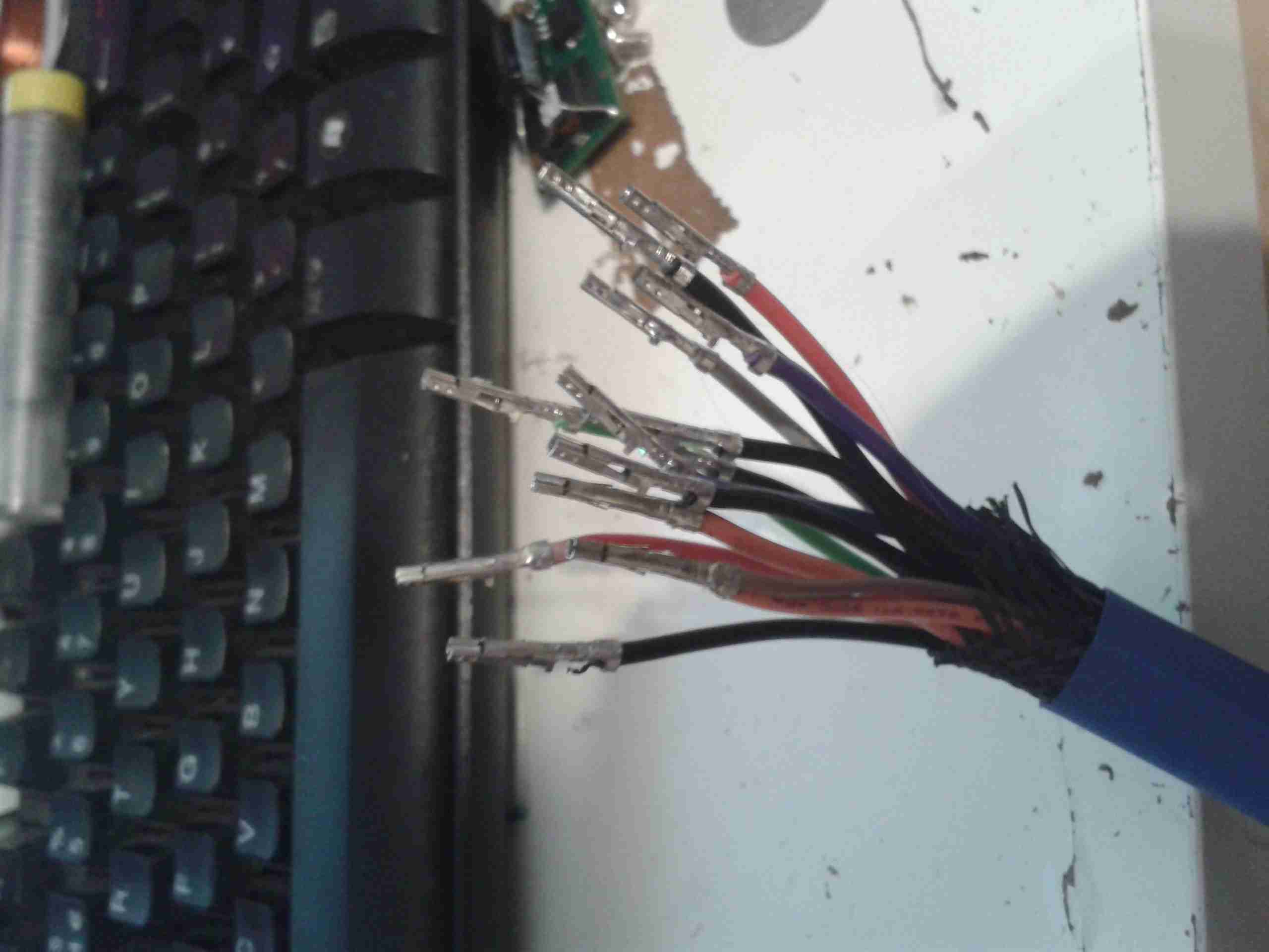
Here’s the partially completed loom, with the 13 cores for the power rails. The 14th pin is left out as that is for AC triggering, and this won’t be usable on a low voltage supply.
A couple of the pins have two wires, this is for voltage sensing at the connector to compensate for any voltage drop across the cable. The regulators I am using have provision for this feature.

Sleeving
Sleeving

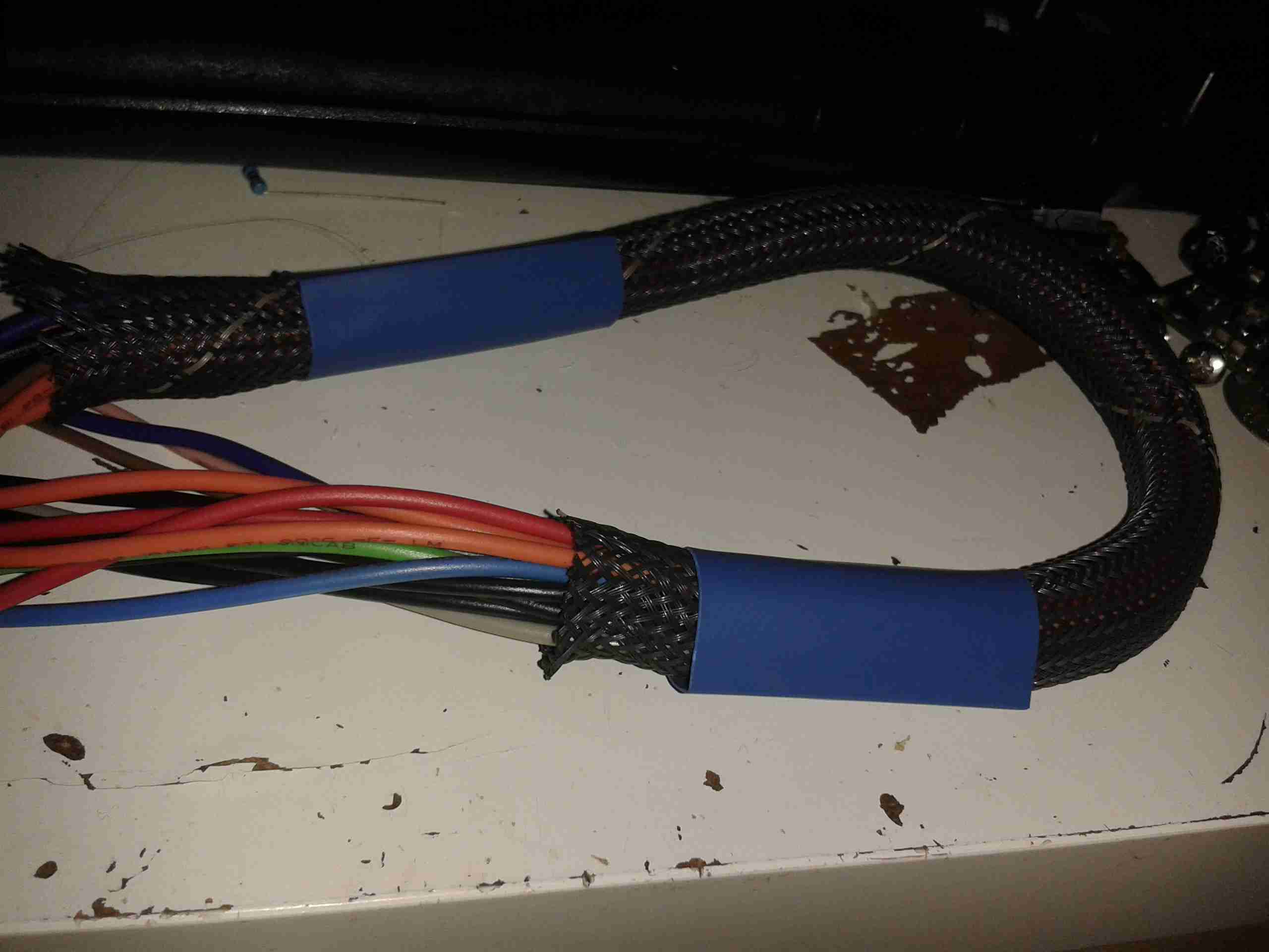
To keep the wiring tidy, I dug a piece of braided loom sleeving out of the parts bin, this will be finished off with the heatshrink once the pins are inserted into the connector shell.
The remaining parts for the loom have been ordered from Farnell & I expect delivery tomorrow.

More to come then!

73s for now 🙂

Posted on Leave a comment

455nm Laser Head

Aixiz Module
Aixiz Module

Here’s my prototype 455nm laser head, constructed from the front section of an Aixiz module threaded into a heatsink from an old ATX power supply. This sink has enough thermal mass for short 1W testing.

Connection
Connection

Connection to the laser diode at the back of the heatsink. Cable is heat shrink covered for strain relief, & hot glued to the sink for extra strain relief.

Beamshot 1
Beamshot 1

Looking down the beam, laser is under the camera. Operating around 1.2W here

Beamshot 2
Beamshot 2

Camera looking towards the laser. Again operating at ~1.2W output power.

Posted on Leave a comment

Chicom “500W” ATX PSU

Cover Removed
Cover Removed

Here is a cheapo 500W rated ATX PSU that has totally borked itself, probably due to the unit NOT actually being capable of 500W. All 3 of the switching transistors were shorted, causing the ensuing carnage:

AC Input
AC Input

Here is the AC input to the PCB. Note the vapourised element inside the input fuse on the left. There is no PFC/filtering built into this supply, being as cheap as it is links have been installed in place of the RFI chokes.

Input Side
Input Side

Main filter capacitors & bridge rectifier diodes. PCB shows signs of excessive heating.

Filter Caps Removed
Filter Caps Removed

Filter capacitors have been removed from the PCB here, showing some cooked components. Resistor & diode next to the heatsink are the in the biasing network for the main switching transistors.

Heatsinks Removed
Heatsinks Removed

Heatsink has been removed, note the remaining pin from one of the switching transistors still attached to the PCB & not the transistor 🙂

Transformers
Transformers

Output side of the PSU, with heatsink removed. Main transformer on  the right, transformers centre & left are the 5vSB  transformer & feedback transformer.

Output Side
Output Side

Output side of the unit, filter capacitors, choke & rectifier diodes are visible here attached to their heatsink.

Comparator
Comparator

Comparator IC that deals with regulation of the outputs & overvoltage protection.