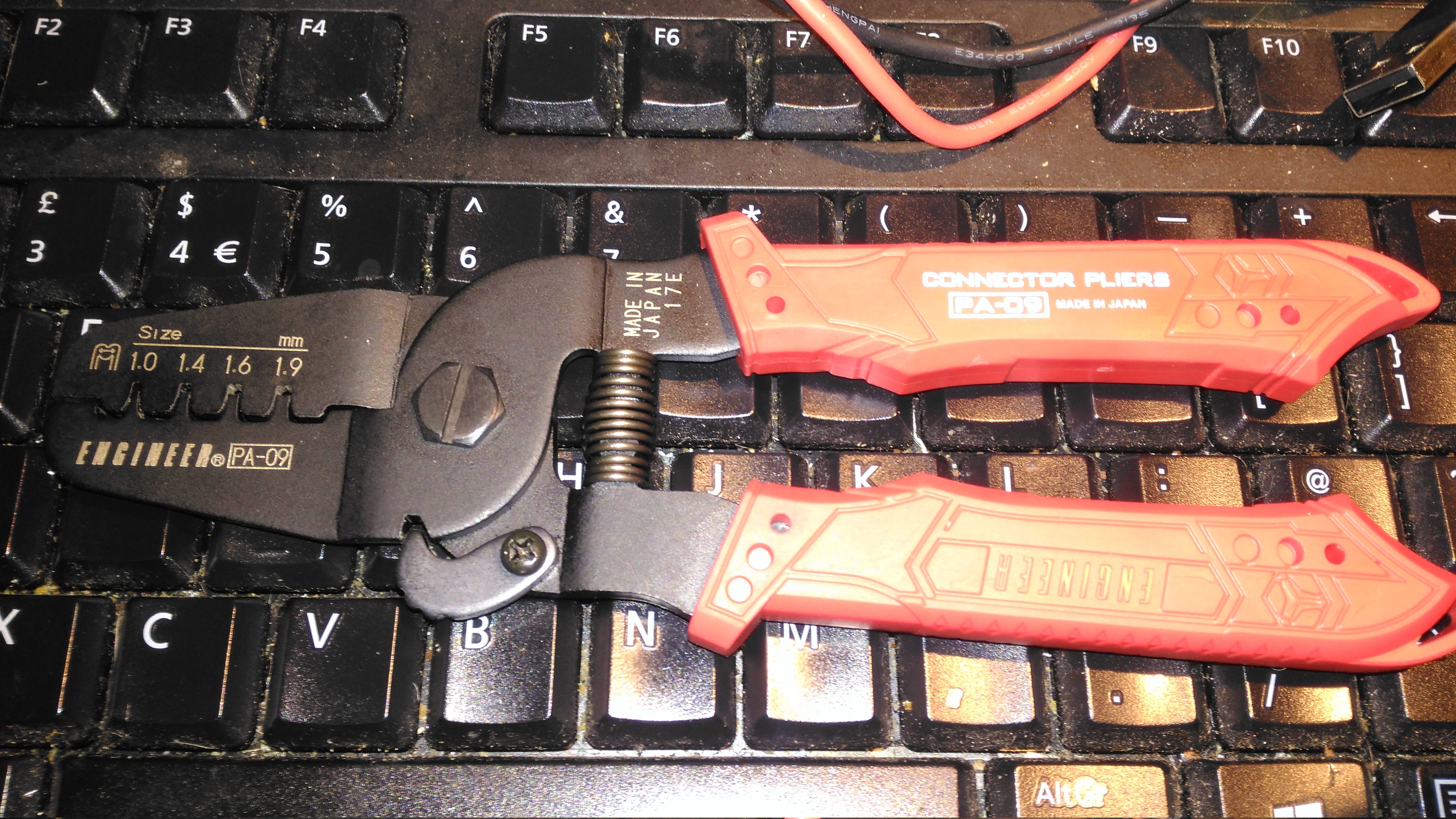
For a while now I’ve been attaching terminals such as Molex KK Dupont, & JST PH to wire ends with a lot of patience & a very fine soldering iron, however this method takes a lot of time, and with terminals like Dupont types, the terminal won’t fit into the connector body properly unless it’s crimped correctly. Official tools from the likes of JST or Molex are hilariously expensive, (~£250 for the Molex KK tool), and each tool only does a single connector series, so these are out of the picture. The cheapest available tool (~£40) for these types of terminals is the Engineer PA-09:
Engineer PA-09
These are simple crimping pliers, with no niceties like a ratchet mechanism, but nonetheless they work very well for the cost. The PA-09 can handle terminals from 1mm-1.9mm, there is another tool, the PA-21, which crimps terminals from 1.6mm-2.5mm. The fit & finish is good – proper steel (S55C high carbon steel according to Engineer), not the steel-plated-cheese that most cheap Chinese tools are fabricated from, the handles are solid & comfortable.
Handles
The rubber handles are press-fit onto the steel frame arms of the pliers, and don’t slip off readily.
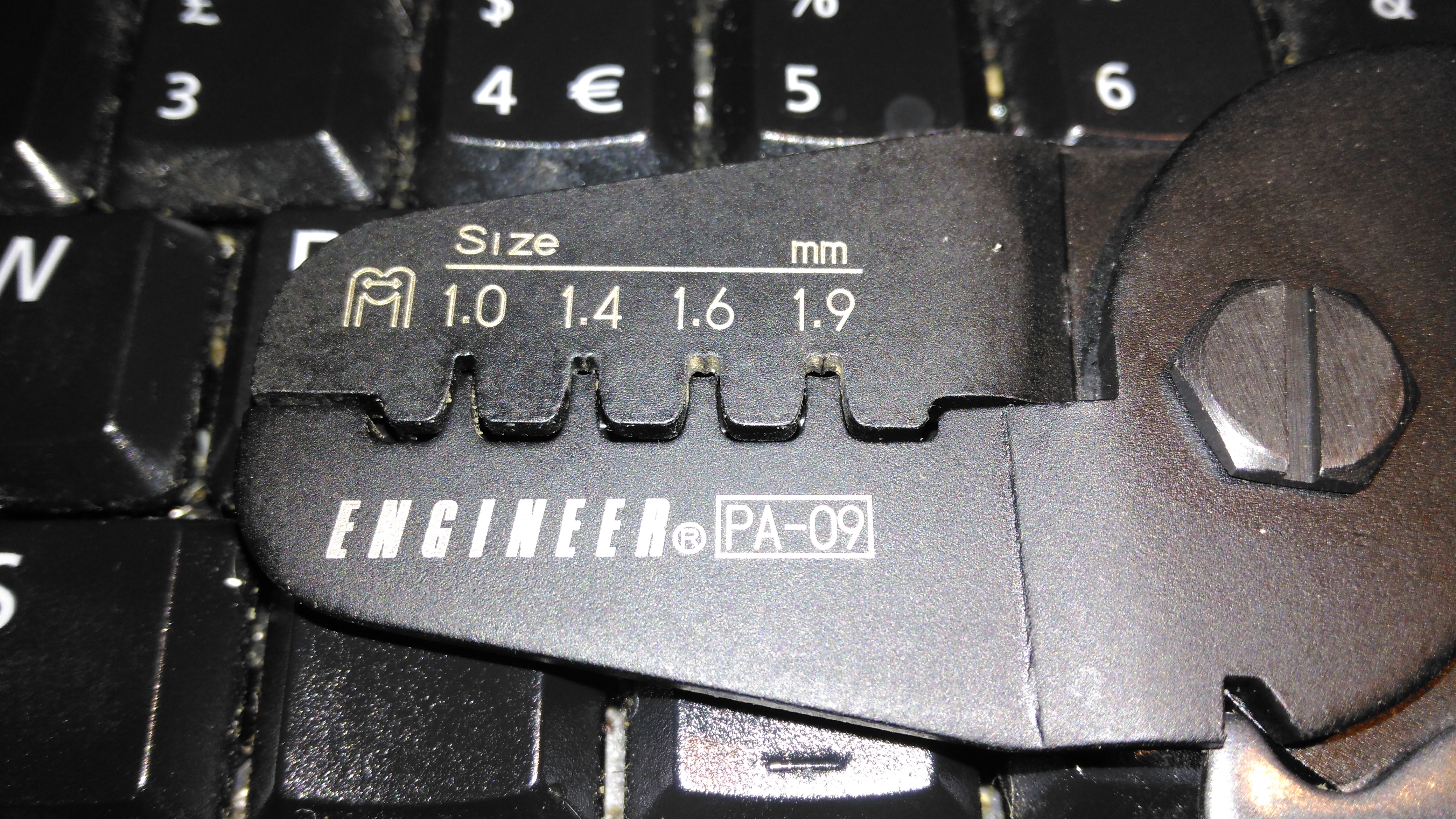
Die Head
The dies are well formed in the steel, and seem to be machined rather than stamped on a press, however the black oxide finish hides any machining marks. The smallest 1mm dies do seem to be a little fragile as they’re so small, so wouldn’t take much abuse without shearing off.
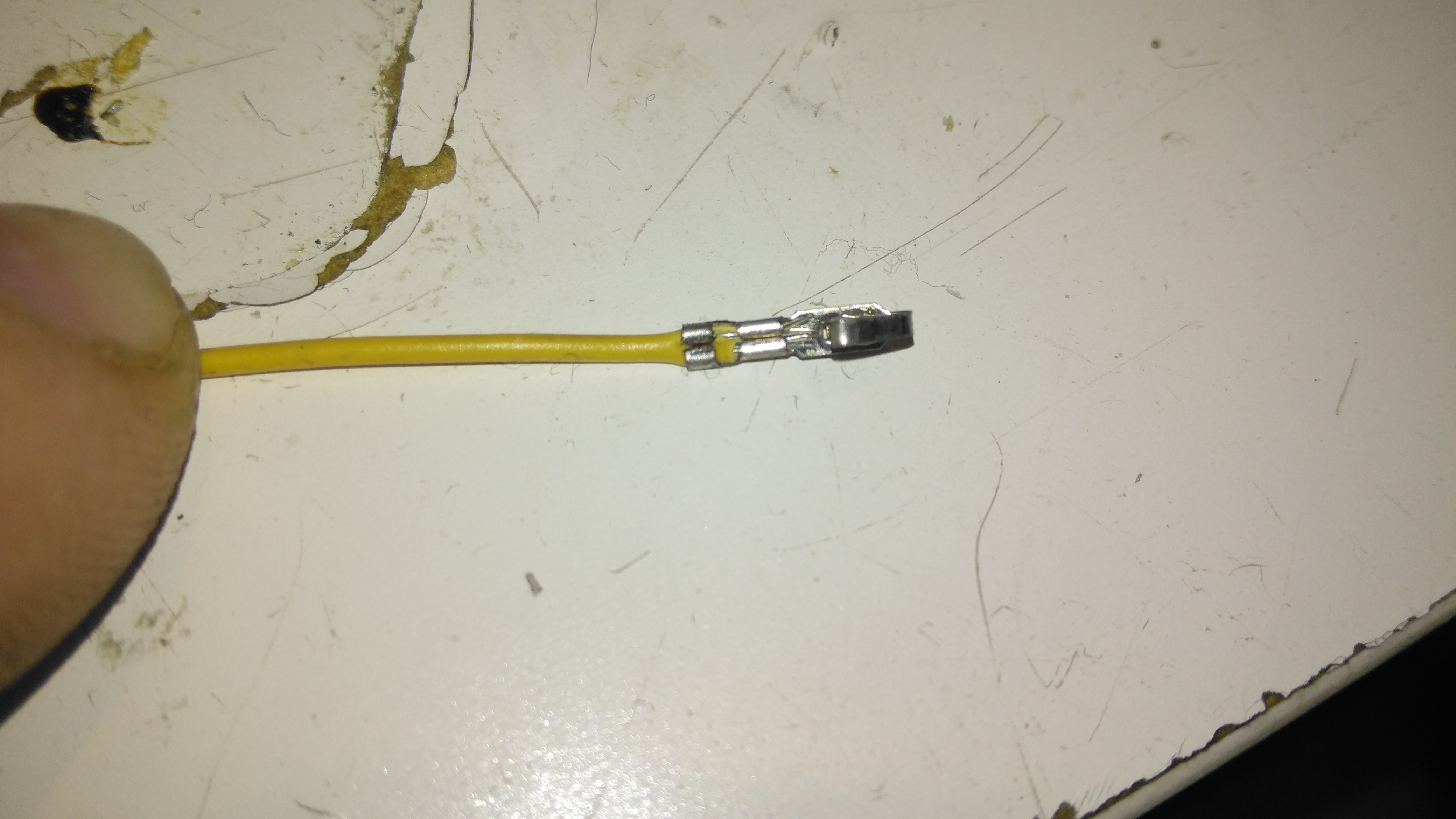
Crimped Molex KK Pin
Here’s a Molex KK pin that’s been crimped with the PA-09. The insulation crimp has pierced the insulation slightly, but this isn’t much of a problem. The conductor crimp is nice & tight, and everything is small enough to fit correctly into the plastic connector body. The trick with these tools is getting a feel for when the crimp is done – squeeze too tightly & the contact deforms, not tightly enough & the wire will just pull out of the terminal. The official tools also crimp both the conductor & insulation at the same time, and they also hold the terminal in place while the wire is inserted. In these cheaper tools, the crimps are done separately, but they do hold on to the contact securely enough for the wire to be inserted properly with your spare hand.
For some time now I’ve been running a large disk array to store all the essential data for my network. The current setup has 10x 4TB disks in a RAID6 array under Linux MD.
Up until now the disks have been running in external Orico 9558U3 USB3 drive bays, through a PCIe x1 USB3 controller. However in this configuration there have been a few issues:
Congestion over the USB3 link. RAID rebuild speeds were severely limited to ~20MB/s in the event of a failure. General data transfer was equally as slow.
Drive dock general reliability. The drive bays are running a USB3 – SATA controller with a port expander, a single drive failure would cause the controller to reset all disks on it’s bus. Instead of losing a single disk in the array, 5 would disappear at the same time.
Cooling. The factory fitted fans in these bays are total crap – and very difficult to get at to change. A fan failure quickly allows the disks to heat up to temperatures that would cause failure.
Upgrade options difficult. These bays are pretty expensive for what they are, and adding more disks to the USB3 bus would likely strangle the bandwidth even further.
Disk failure difficult to locate. The USB3 interface doesn’t pass on the disk serial number to the host OS, so working out which disk has actually failed is difficult.
To remedy these issues, a proper SATA controller solution was required. Proper hardware RAID controllers are incredibly expensive, so they’re out of the question, and since I’m already using Linux MD RAID, I didn’t need a hardware controller anyway.
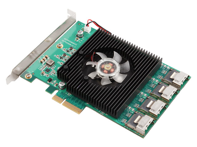
16-Port HBA
A quick search for suitable HBA cards showed me the IOCrest 16-port SATAIII controller, which is pretty low cost at £140. This card breaks out the SATA ports into standard SFF-8086 connectors, with 4 ports on each. Importantly the cables to convert from these server-grade connectors to standard SATA are supplied, as they’re pretty expensive on their own (£25 each).
This card gives me the option to expand the array to 16 disks eventually, although the active array will probably be kept at 14 disks with 2 hot spares, this will give a total capacity of 48TB.
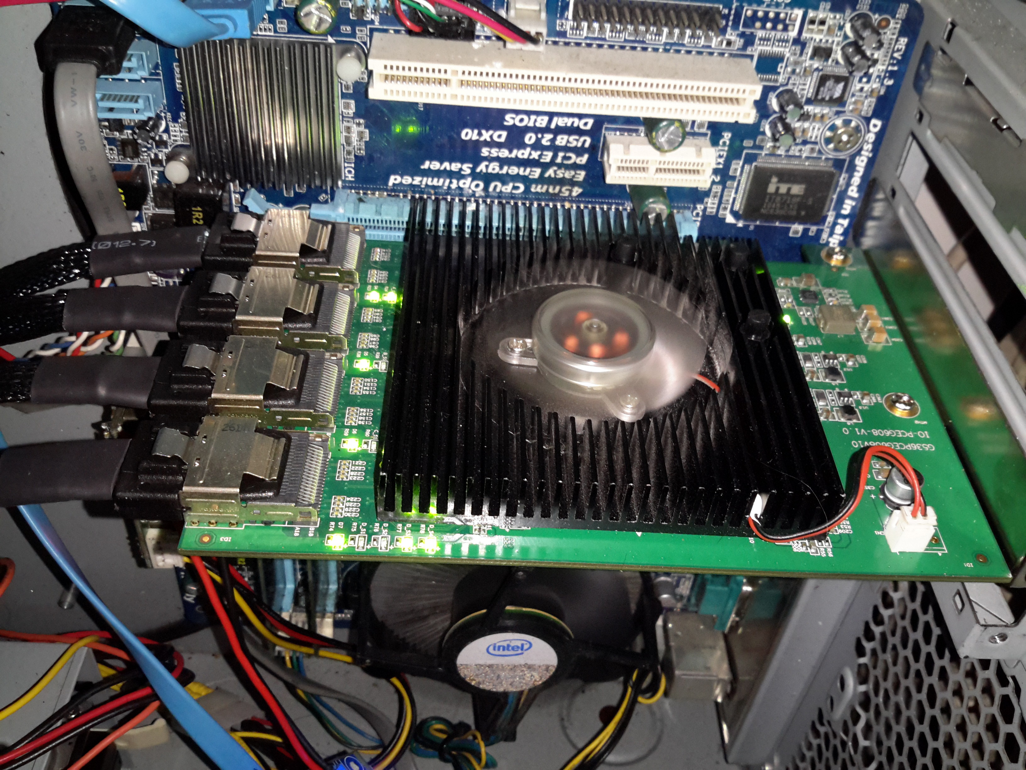
SATA HBA
Here’s the card installed in the host machine, with the array running. One thing I didn’t expect was the card to be crusted with activity LEDs. There appears to be one LED for each pair of disks, plus a couple others which I would expect are activity on the backhaul link to PCIe. (I can’t be certain, as there isn’t any proper documentation anywhere for this card. It certainly didn’t come with any ;)).
I’m not too impressed with the fan that’s on the card – it’s a crap sleeve bearing type, so I’ll be keeping a close eye on this for failure & will replace with a high quality ball-bearing fan when it finally croaks. The heatsink is definitely oversized for the job, with nothing installed above the card barely gets warm, which is definitely a good thing for life expectancy.
Update 10/02/17 – The stock fan is now dead as a doornail after only 4 months of continuous operation. Replaced with a high quality ball-bearing 80mm Delta fan to keep things running cool. As there is no speed sense line on the stock fan, the only way to tell it was failing was by the horrendous screeching noise of the failing bearings.
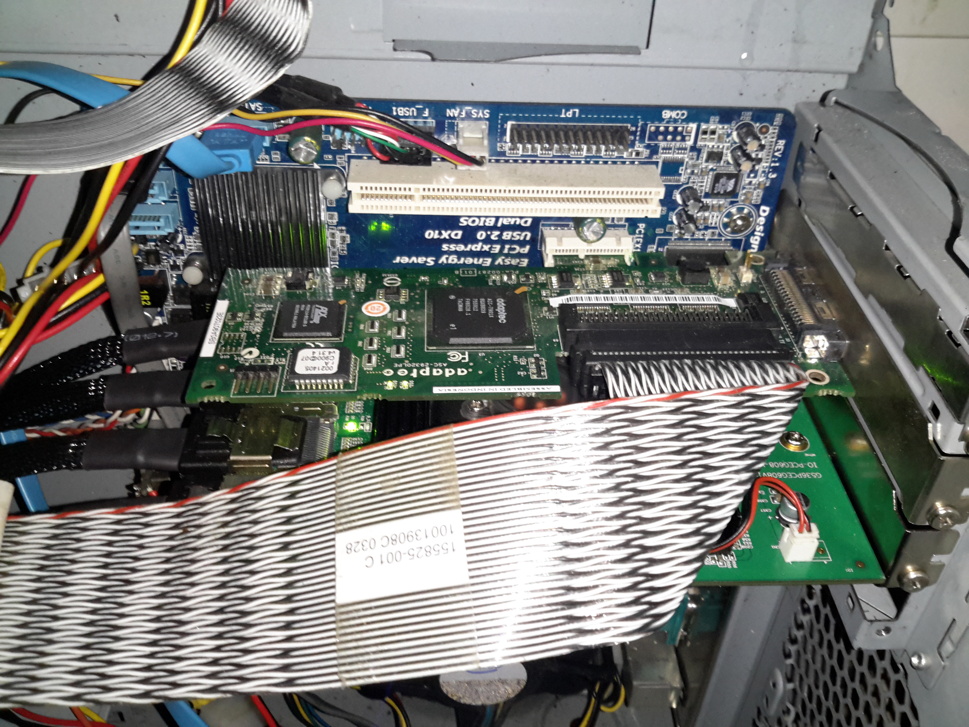
SCSI Controller
Above is the final HBA installed in the PCIe x1 slot above – a parallel SCSI U320 card that handles the tape backup drives. This card is very close to the cooling fan of the SATA card, and does make it run warmer, but not excessively warm. Unfortunately the card is too long for the other PCIe socket – it fouls on the DIMM slots.
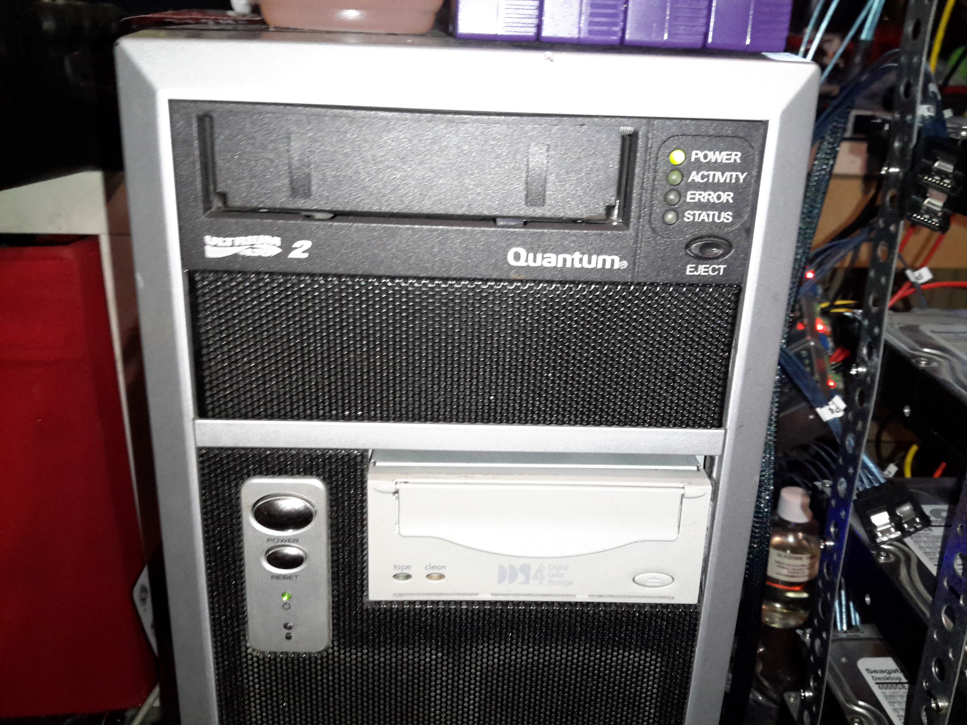
Backup Drives
The tape drives are LTO2 300/600GB for large file backup & DDS4 20/40GB DAT for smaller stuff. These were had cheap on eBay, with a load of tapes. Newer LTO drives aren’t an option due to cost.
The main disk array is currently built as 9 disks in service with a single hot spare, in case of disk failure, this gives a total size after parity of 28TB:
/dev/md0:
        Version : 1.2
  Creation Time : Wed Mar 11 16:01:01 2015
     Raid Level : raid6
     Array Size : 27348211520 (26081.29 GiB 28004.57 GB)
  Used Dev Size : 3906887360 (3725.90 GiB 4000.65 GB)
   Raid Devices : 9
  Total Devices : 10
    Persistence : Superblock is persistent

  Intent Bitmap : Internal

    Update Time : Mon Nov 14 14:28:59 2016
          State : active
 Active Devices : 9
Working Devices : 10
 Failed Devices : 0
  Spare Devices : 1

         Layout : left-symmetric
     Chunk Size : 64K

           Name : Main-PC:0
           UUID : 266632b8:2a8a3dd3:33ce0366:0b35fad9
         Events : 773938

    Number   Major   Minor   RaidDevice State
       0       8       48        0      active sync   /dev/sdd
       1       8       32        1      active sync   /dev/sdc
       9       8       96        2      active sync   /dev/sdg
      10       8      112        3      active sync   /dev/sdh
      11       8       16        4      active sync   /dev/sdb
       5       8      176        5      active sync   /dev/sdl
       6       8      144        6      active sync   /dev/sdj
       7       8      160        7      active sync   /dev/sdk
       8       8      128        8      active sync   /dev/sdi

      12       8        0        -      spare   /dev/sda
The disks used are Seagate ST4000DM000 Desktop HDDs, which at this point have ~15K hours on them, and show no signs of impending failure.
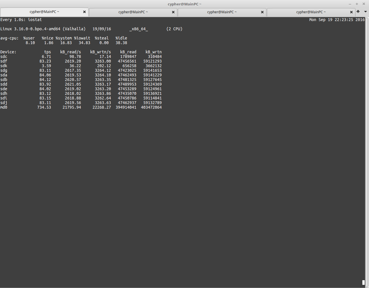
USB3 Speeds
Here’s a screenshot with the disk array fully loaded running over USB3. The aggregate speed on the md0 device is only 21795KB/s. Extremely slow indeed.
This card is structured similarly to the external USB3 bays – a PCI Express bridge glues 4 Marvell 9215 4-port SATA controllers into a single x8 card. Bus contention may become an issue with all 16 ports used, but as far with 9 active devices, the performance increase is impressive. Adding another disk to the active array would certainly give everything a workout, as rebuilding with an extra disk will hammer both read from the existing disks & will write to the new.
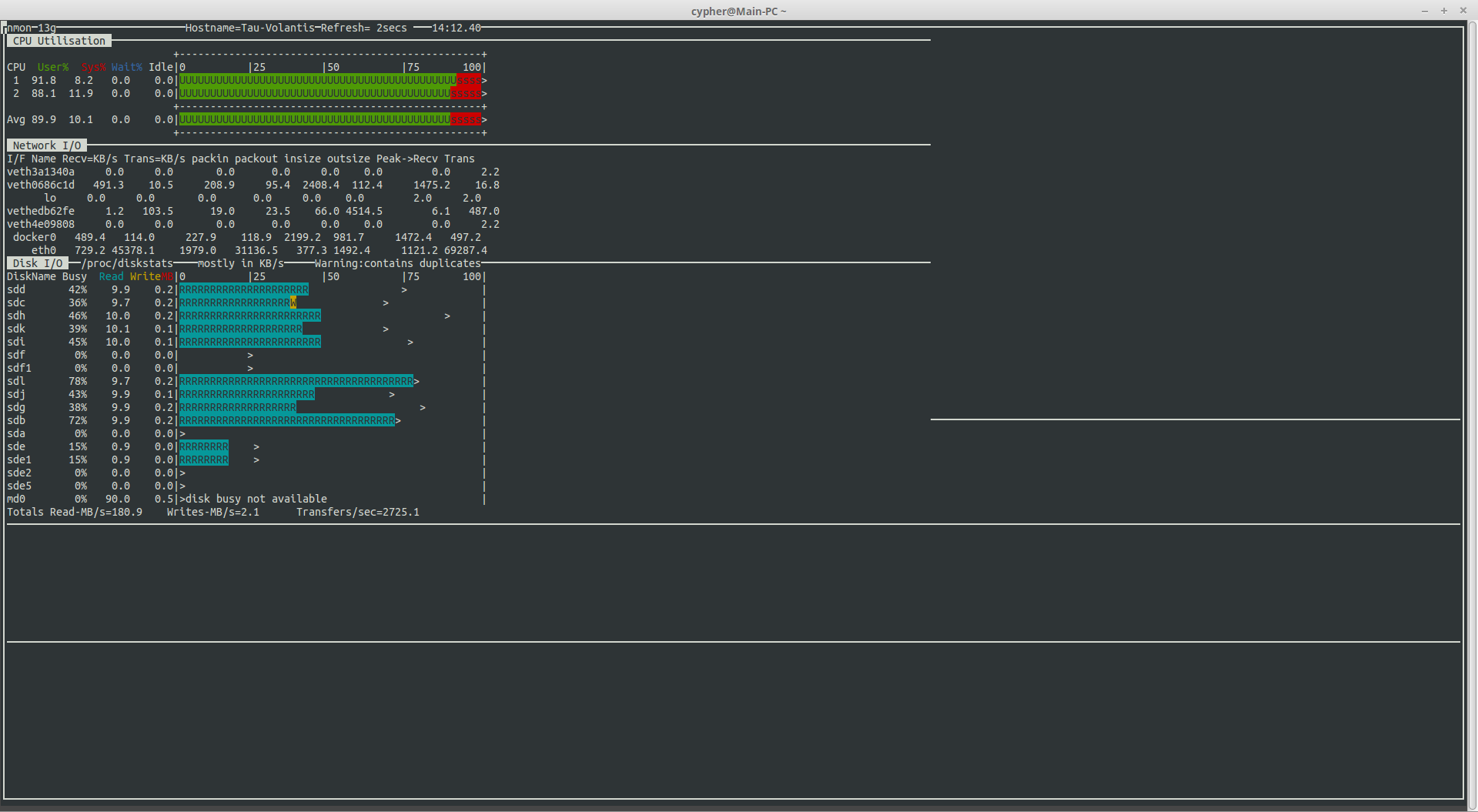
HBA Speeds
With all disks on the new controller, I’m sustaining read speeds of 180MB/s. (Pulling data off over the network). Write speeds are always going to be pretty pathetic with RAID6, as parity calculations have to be done. With Linux MD, this is done by the host CPU, which is currently a Core2Duo E7500 at 2.96GHz, with this setup, I get 40-60MB/s writes to the array with large files.
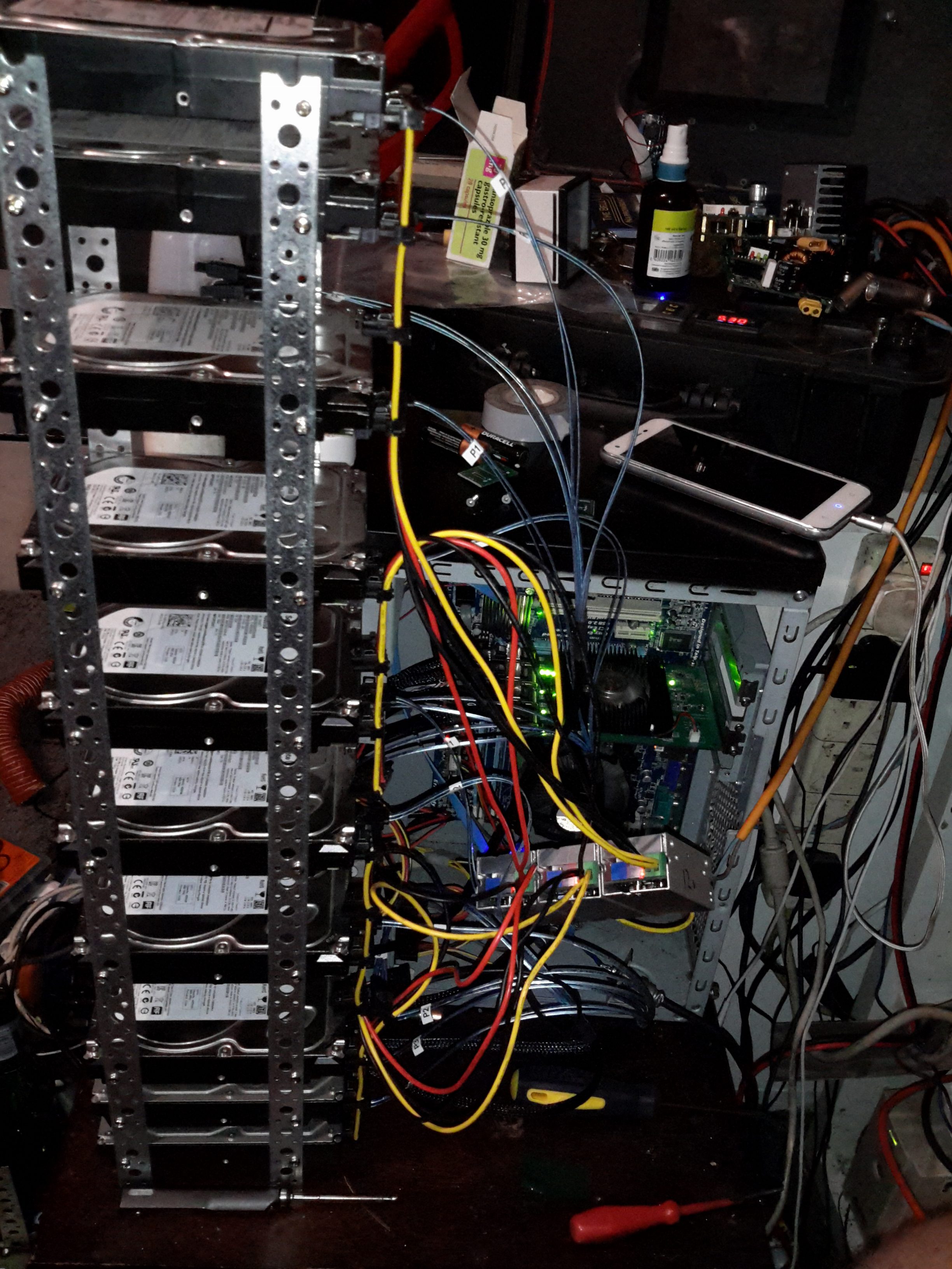
Disk Array
Since I don’t have a suitable case with built in drive bays, (again, they’re expensive), I’ve had to improvise with some steel strip to hold the disks in a stack. 3 DC-DC converters provides the regulated 12v & 5v for the disks from the main unregulated 12v system supply. Both the host system & the disks run from my central battery-backed 12v system, which acts like a large UPS for this.
The SATA power splitters were custom made, the connectors are Molex 67926-0001 IDC SATA power connectors, with 18AWG cable to provide the power to 4 disks in a string.
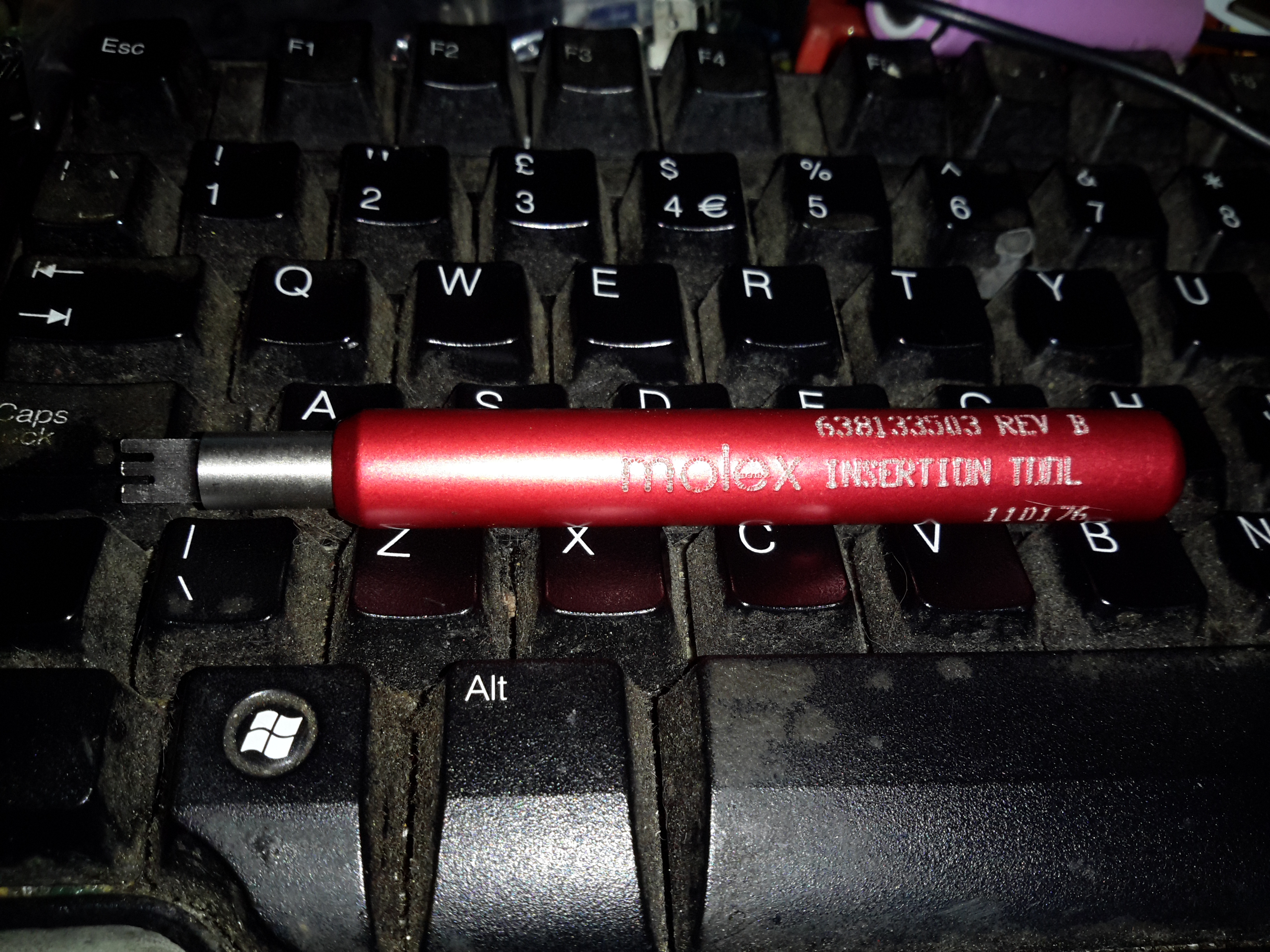
IDT Insertion Tool
These require the use of a special tool if you value your sanity, which is a bit on the expensive side at £25+VAT, but doing it without is very difficult. You get a very well made tool for the price though, the handle is anodised aluminium & the tool head itself is a 300 series stainless steel.
For the latest big project, replacing the battery bank on the boat with 5 brand new 200Ah Yuasa heavy duty flooded lead acids, I’m going to need to make many short links from heavy battery cable to connect all 5 batteries into a parallel bank.
Cutting cable as big in diameter as a good sized thumb is difficult at best. In the past I’ve used a hacksaw, but it doesn’t do a very clean job, especially as the cut nears the end – strands get ripped from the cable by the relatively coarse blade & this reduces the current carrying capacity.
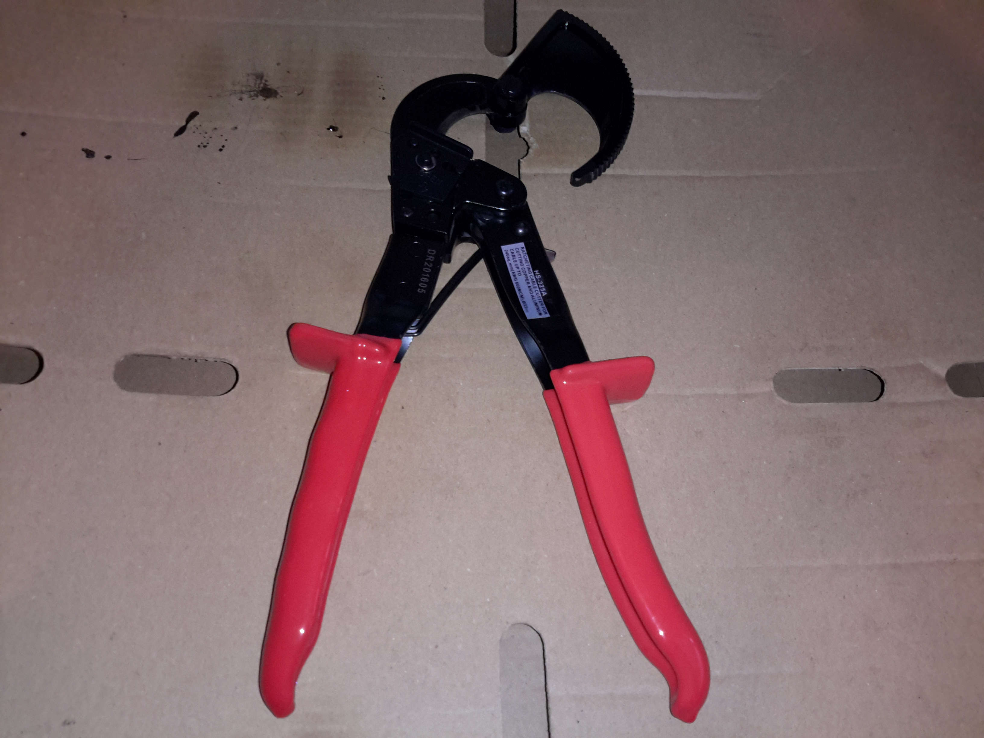
Over to eBay again netted a pair of ratchet-type heavy duty cable cutters for £30. These are rated to cut cable up to 240mm² or 600MCM.
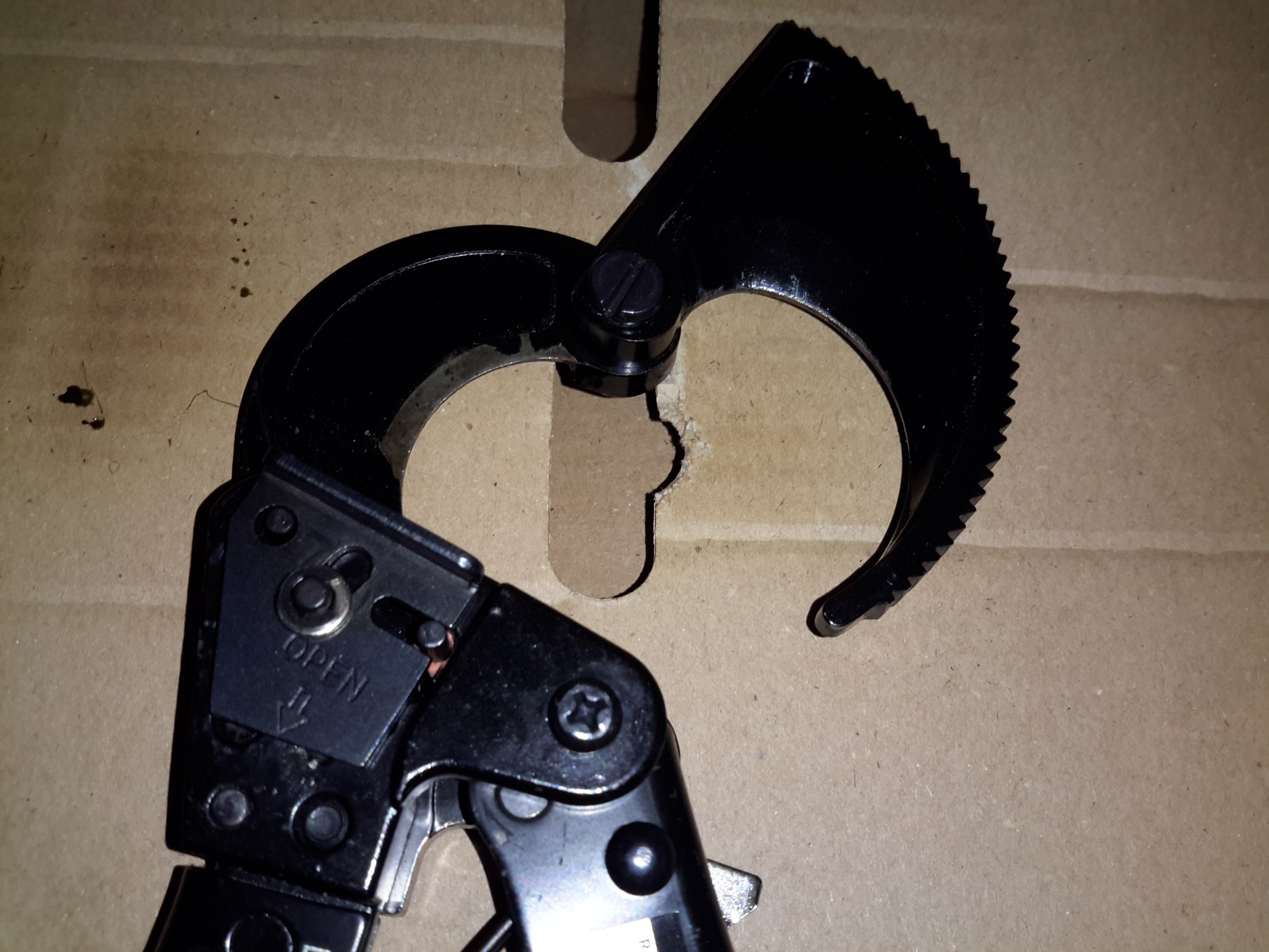
Cutting Jaws
The cutting head on these snips is massive – cutting through cable up to 35mm in diameter takes some force. The ratchet mechanism is used to get a large mechanical advantage to force the cutters through the copper, without having to resort to more expensive & complex mechanisms such as hydraulics. (Hydraulic cable cutters do exist, but cost a small fortune & are totally over-rated for the job).
Overall the tool seems to be well made, the handles are Vinyl dipped to make them more comfortable, which certainly helps when applying a large amount of force. Running a file over the cutters themselves reveals they’re actually hardened – unusual for cheapo Chinese tools.
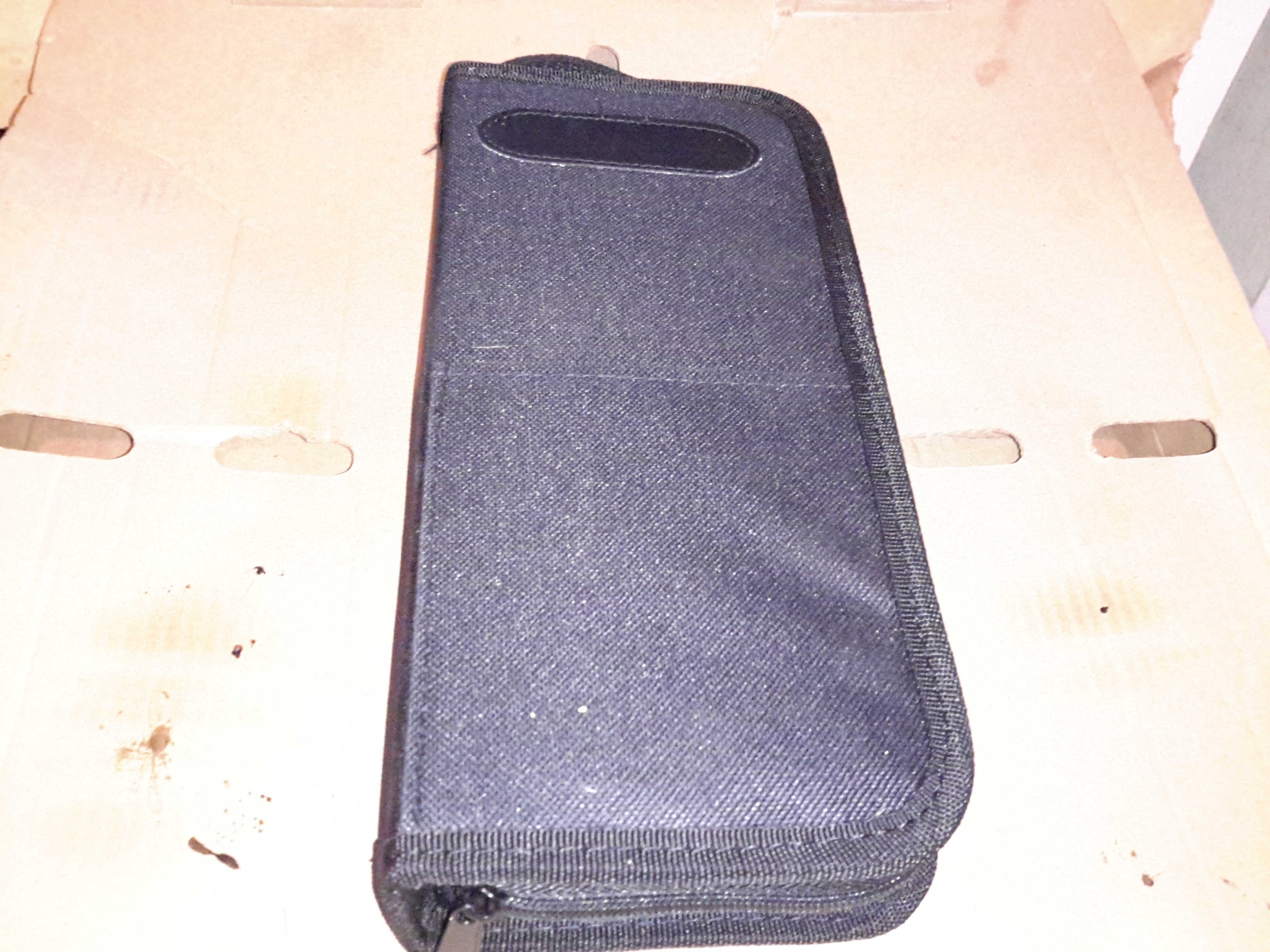
I recently decided to restock my toolkit, as there are plenty of jobs I need to sort that require the use of crimp terminals, so eBay again came to the rescue.
In my experience, cheap tools of any flavour are usually universally shite – I’ve had drill bits made out of a metal softer than aluminium, that unwind back into a straight flute bits as soon as they’re presented with anything harder to drill through than Cheese. Ditto for screwdrivers. But for once the far eastern factories seem to have done a reasonable job on this crimp tool set.
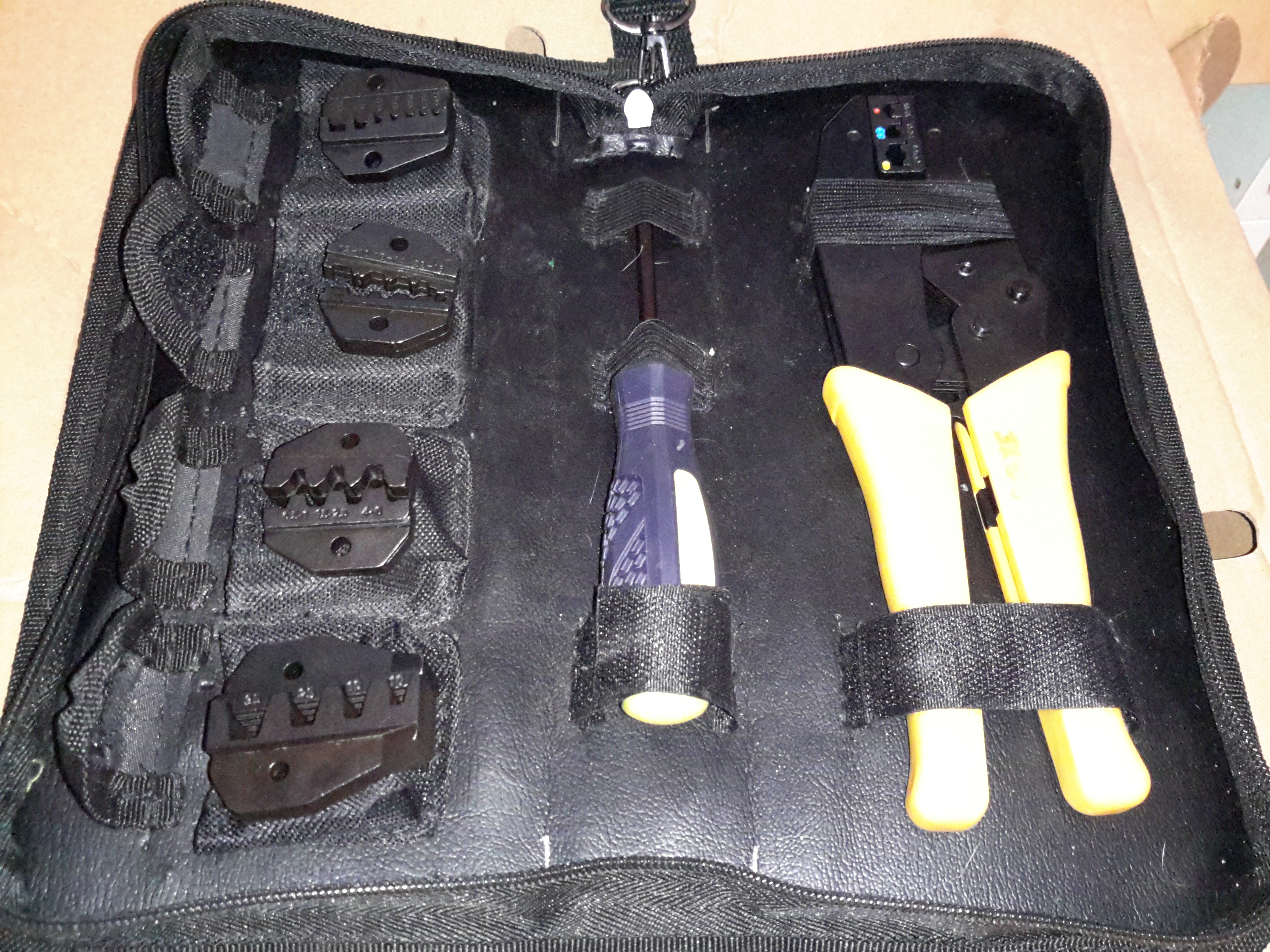
eBay Crimping Tools
These are ratchet type crimping pliers, with interchangable heads so many different types of terminals can be used. A handy Philips screwdriver is included in the kit for changing the dies.
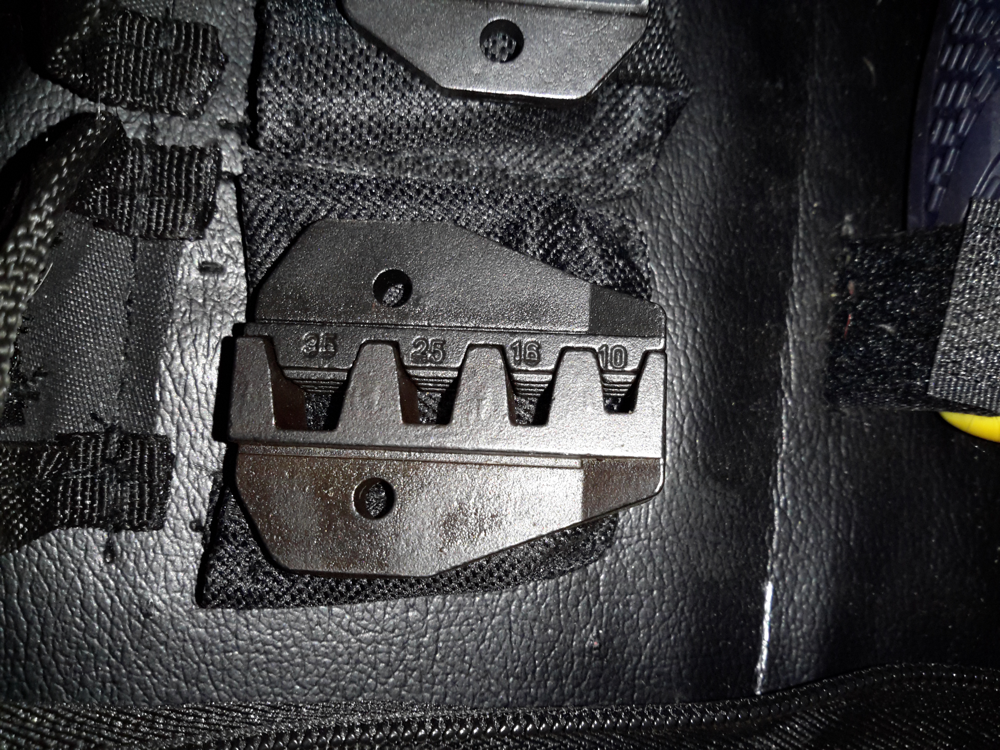
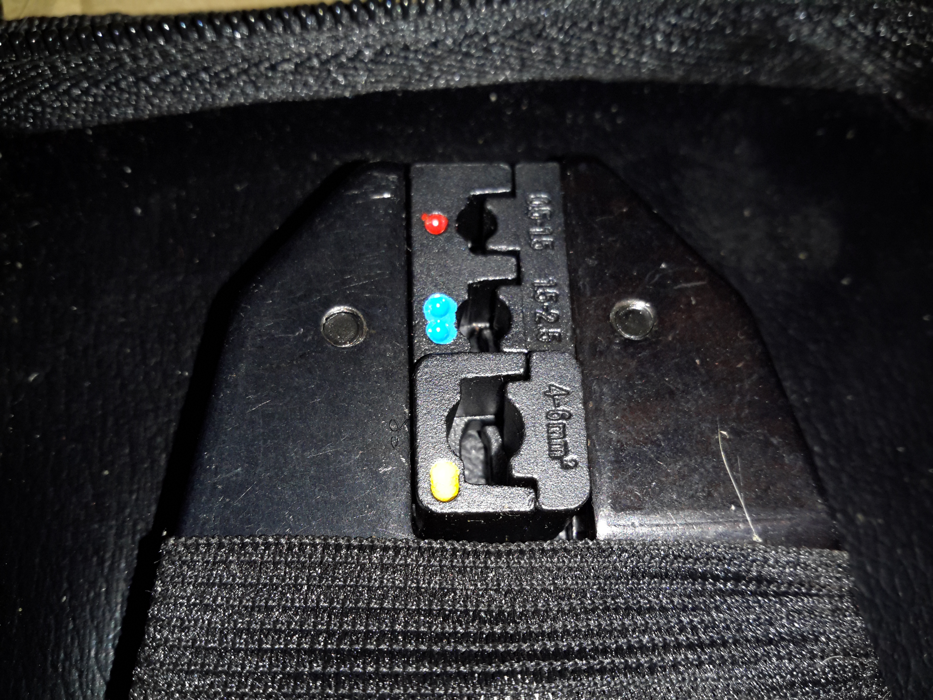
Large Dies
The largest dies in the set can handle cable up to 25mm² – just about the bottom end of main battery cables, which is very handy.
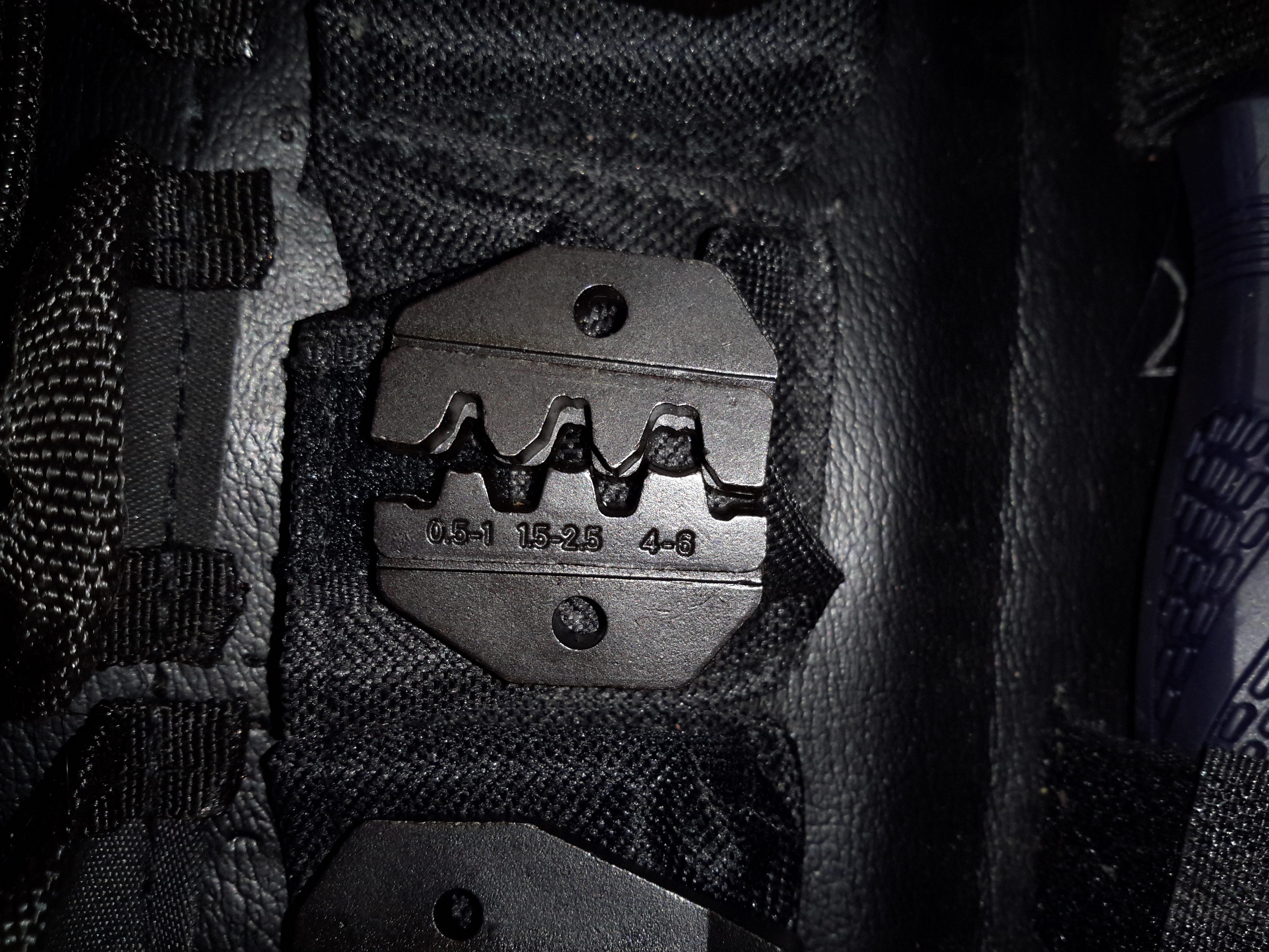
Medium Dies
Smaller sets of dies are provided for other types of terminals.
Small Dies
I’m not precisely sure which type of terminals these dies fit – the profile is a bit unusual.
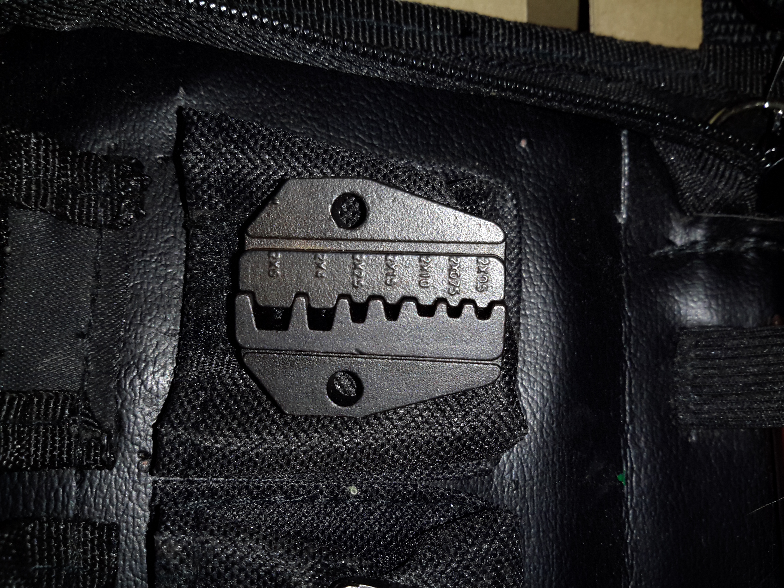
Tiny Dies
The smallest dies in the set are good for extremely small wires – down to 0.5mm
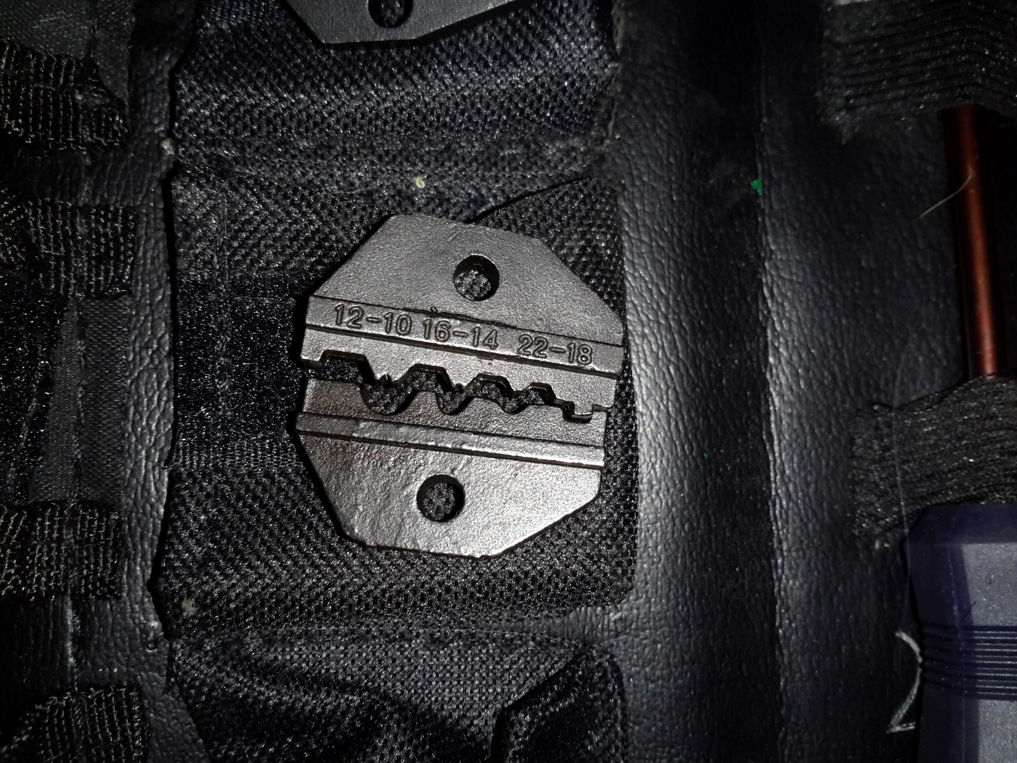
Automotive Dies
The pliers are supplied with the standard colour-coded automotive dies installed. Sometimes these terminals never crimp properly, as the dies just effectively crush the copper tube of the terminal, so more often than not the wire strands are just forced out of the terminal as the crimp is made, leaving a bad connection.
These are even better than the ratchet-type crimp tools at the local Maplin Electronics – the set of those I have just distorts when a large crimp is made, so the terminal never gets a full crimp. The steel is not stiff enough to handle the forces required.
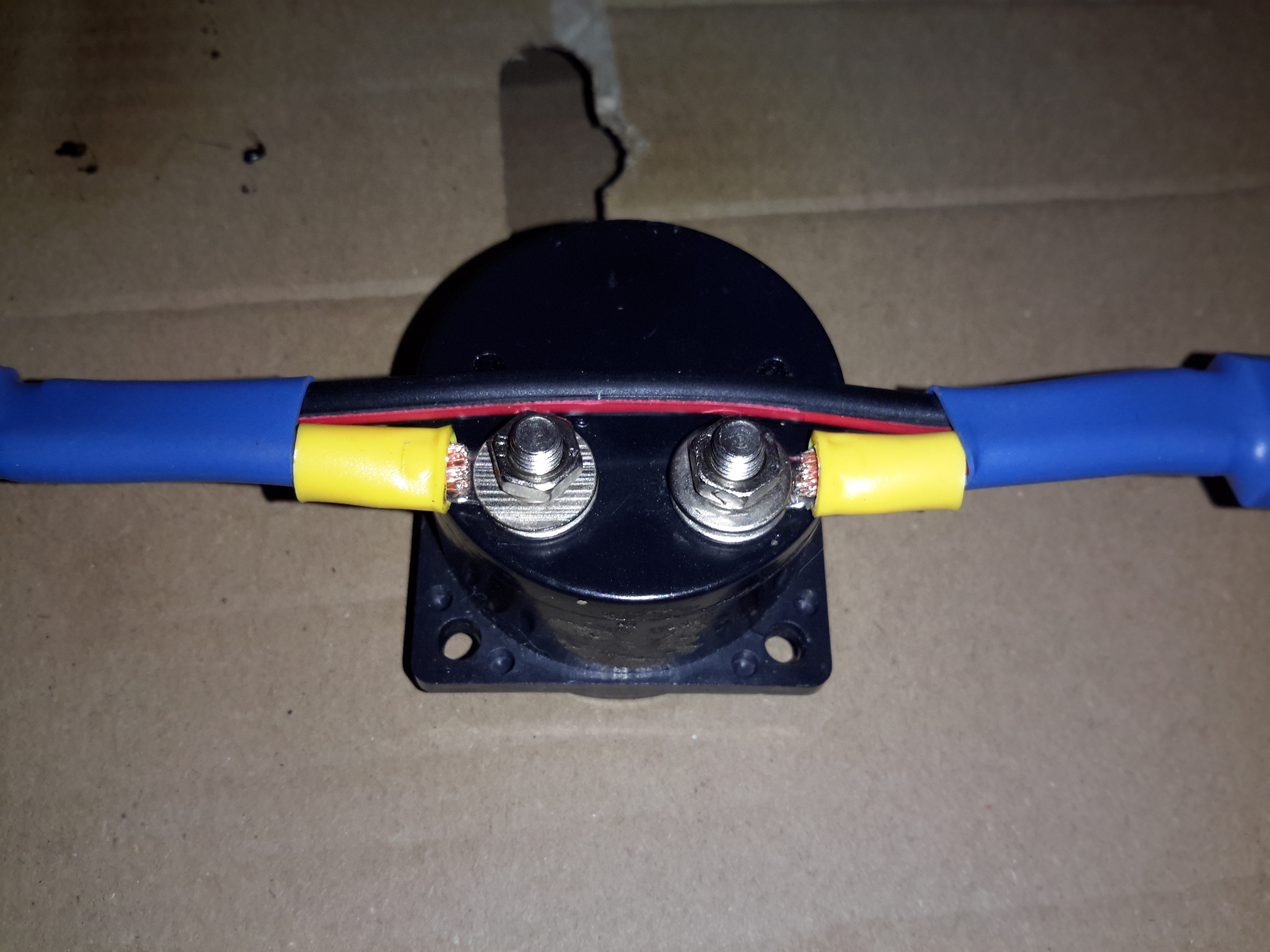
Example Crimp
Here’s a couple of large crimps on 6mm² cable attached to an ammeter. The crimps are nice & tight & hold onto the cable securely. The insulating sleeve on the terminals also hasn’t been cut through by the dies, which is often a problem on cheap crimp tools.
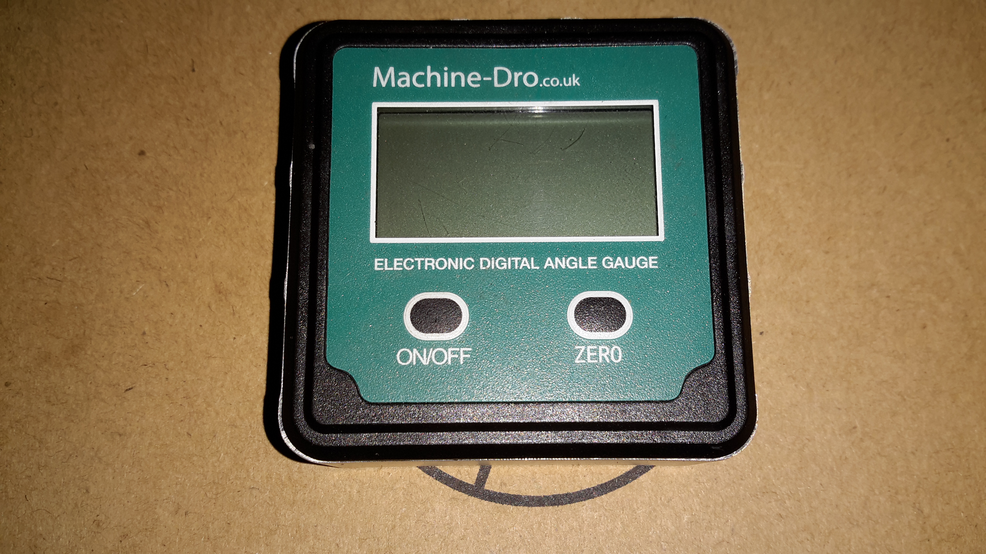
Here’s a useful tool for the kit, a digital angle gauge/protractor. These use a silicon sensor to show the number of degrees the unit is out of level.
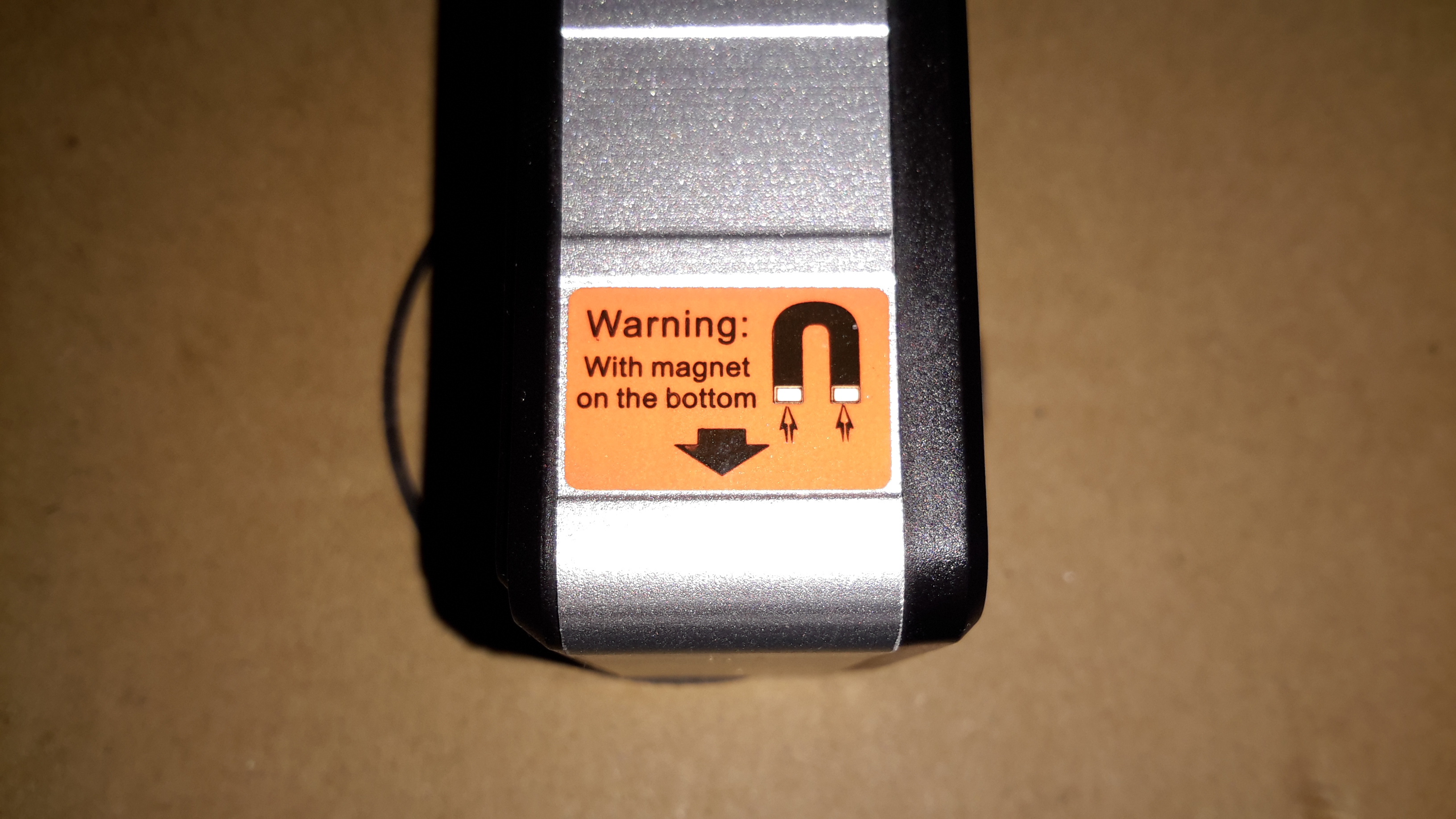
Magnets!
Magnets are provided in the base, so the tool can attach to any ferrous surface.
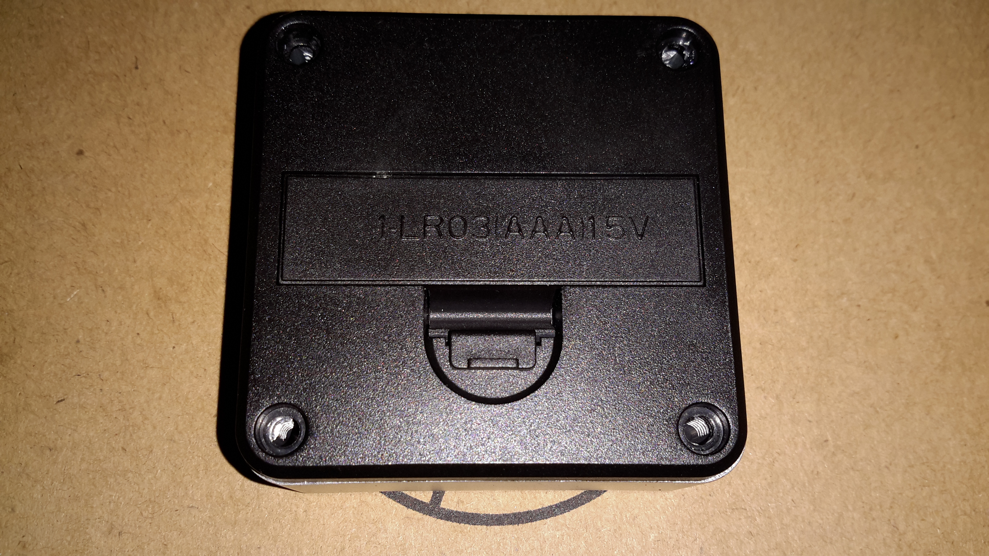
Battery Box
Power is provided by a single AAA cell.
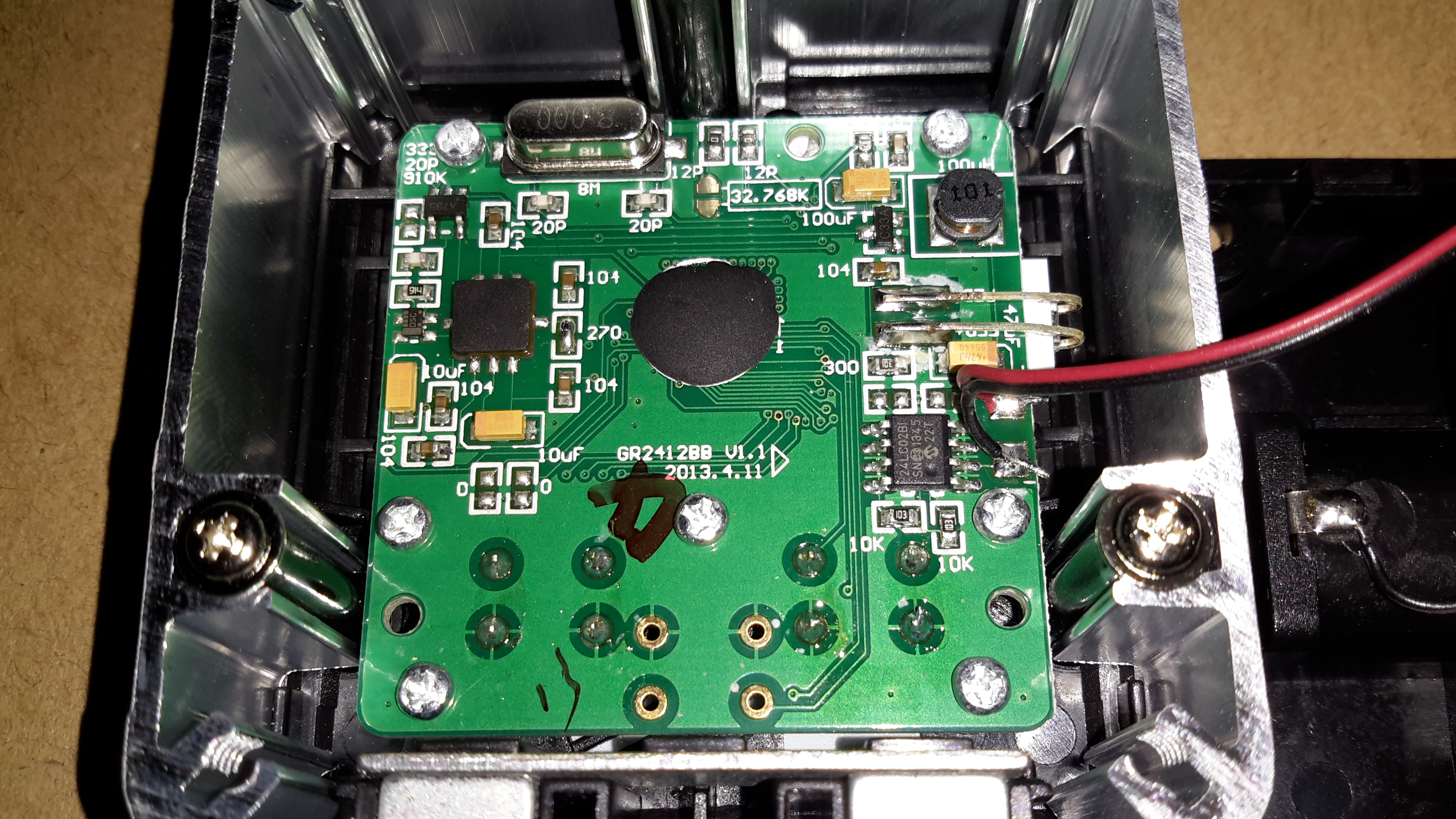
Main PCB
Removing the rear cover reveals the brains of the unit, and there’s not much to it at all. The main microcontroller is a CoB-type device, so no part numbers available from that one.
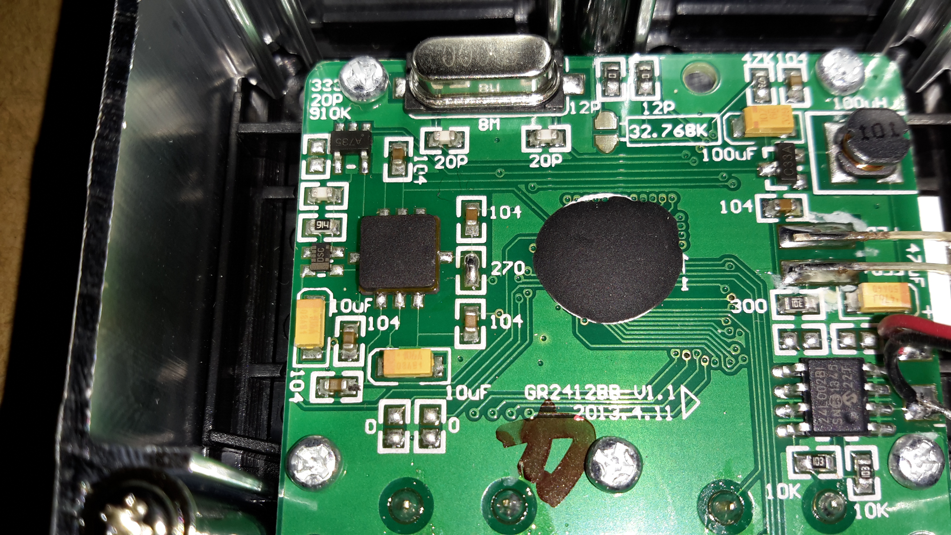
Sensing Element
The IC to the left of the main microcontroller is the sensing element. There’s no markings on this inclinometer IC so I’m not sure of the specs, but it will be a 3D-MEMS device of some sort.
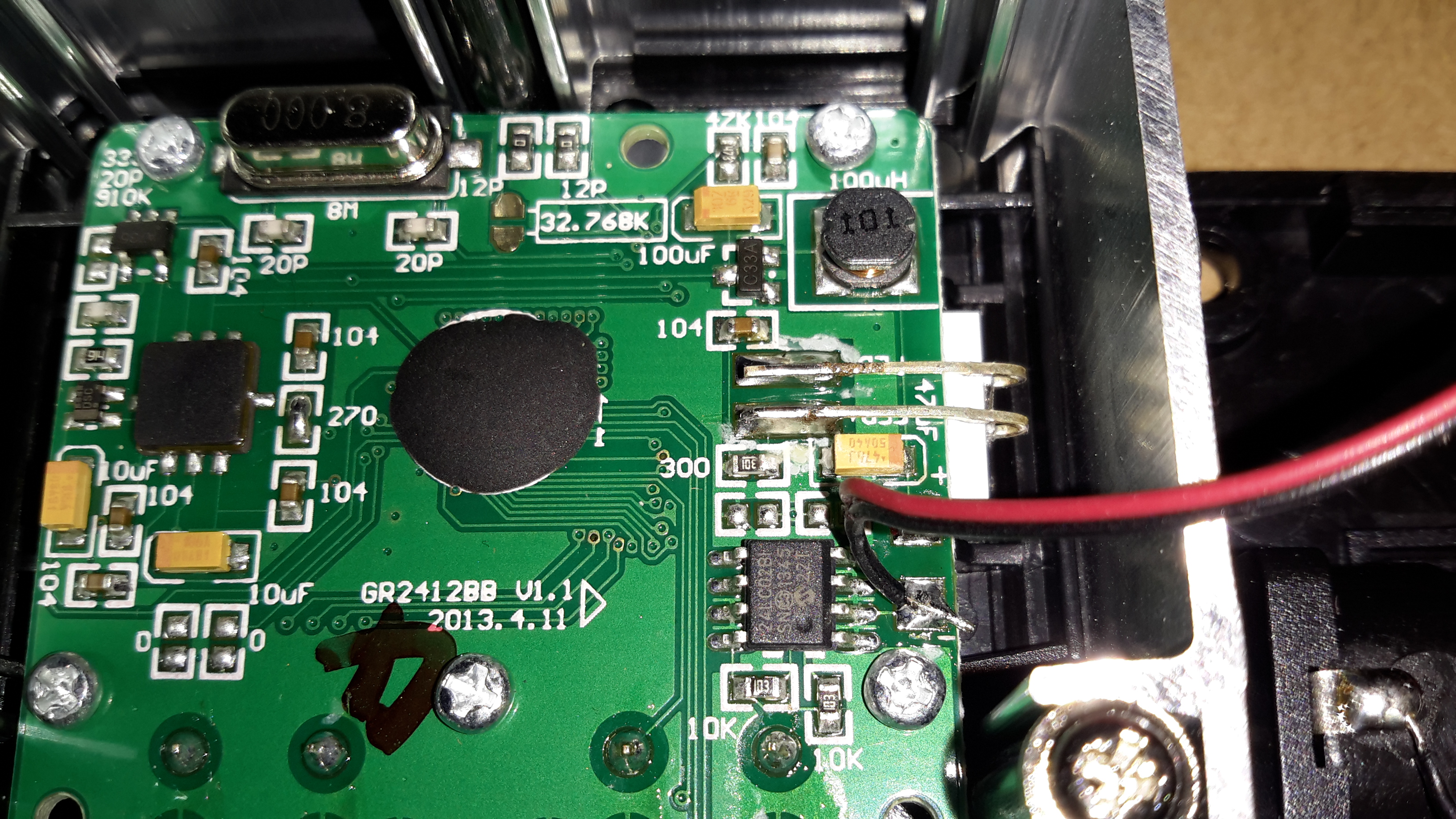
Power Supply
The other side of the PCB has the power supply for the logic, and a serial EEPROM, probably storing calibration data.
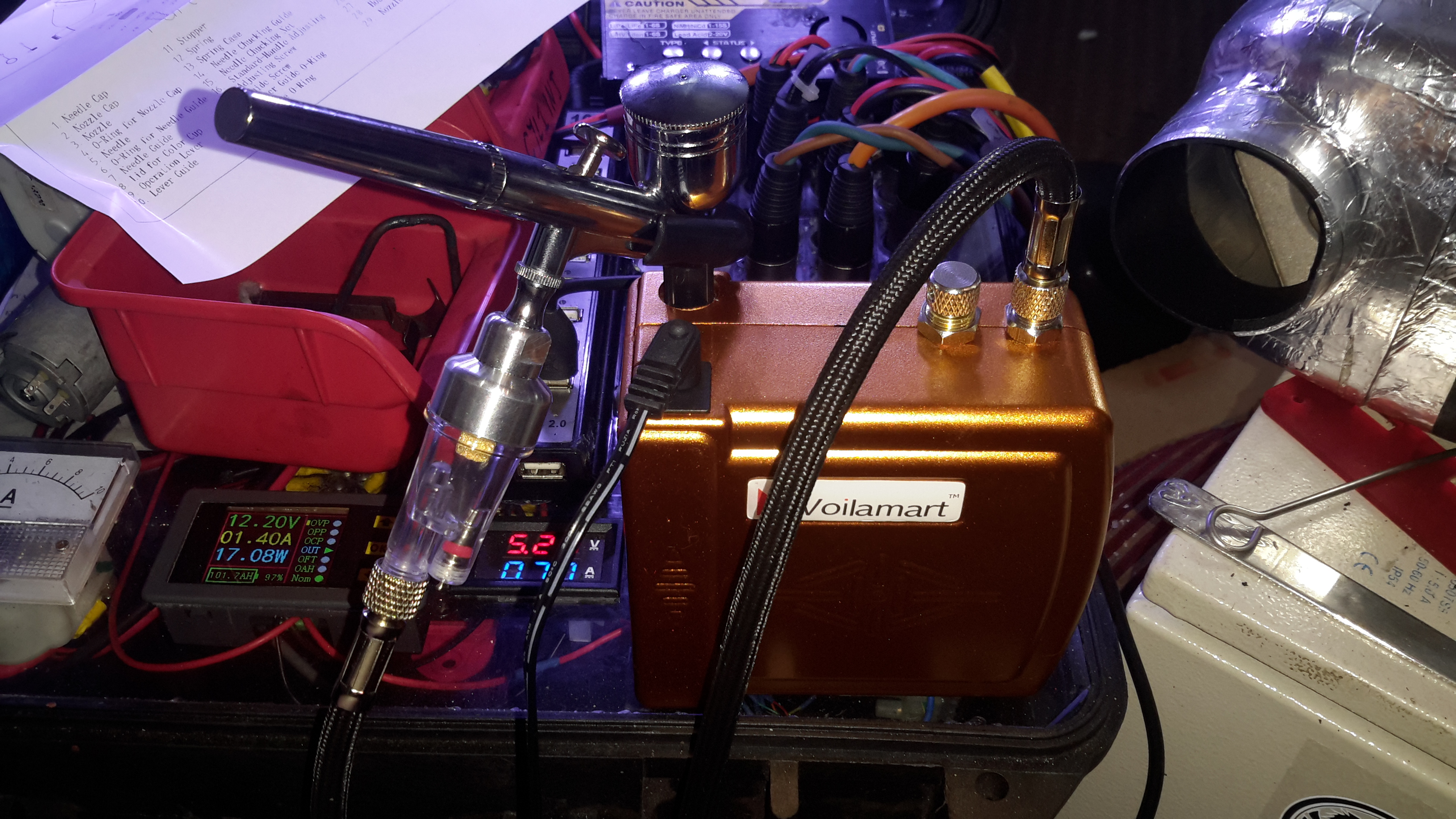
For my latest project, I needed an easier way to paint without messing about with brushes, and the associated marks they leave in a paint job. eBay provided me with a cheap airbrush & compressor.
Airbrush Kit
For less than £30, this kit doens’t look so bad. I’ve never used an airbrush before, but I’ve had no problems with this as yet spraying both water based paints & solvent based paints.
Compressor
Here’s the compressor itself, this runs on 12v & has an output pressure of 1.5 Bar, which is supposed to be adjustable.
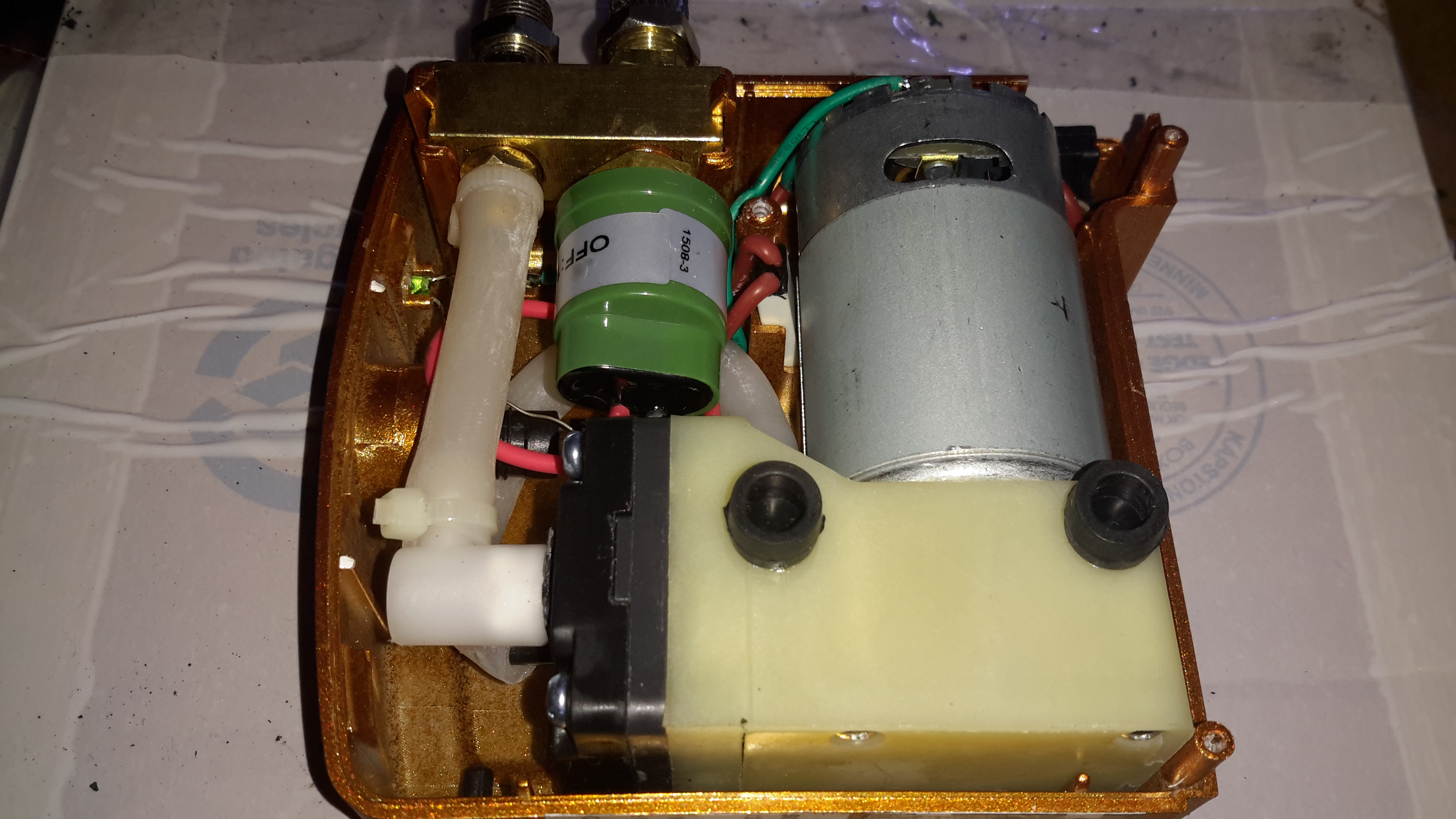
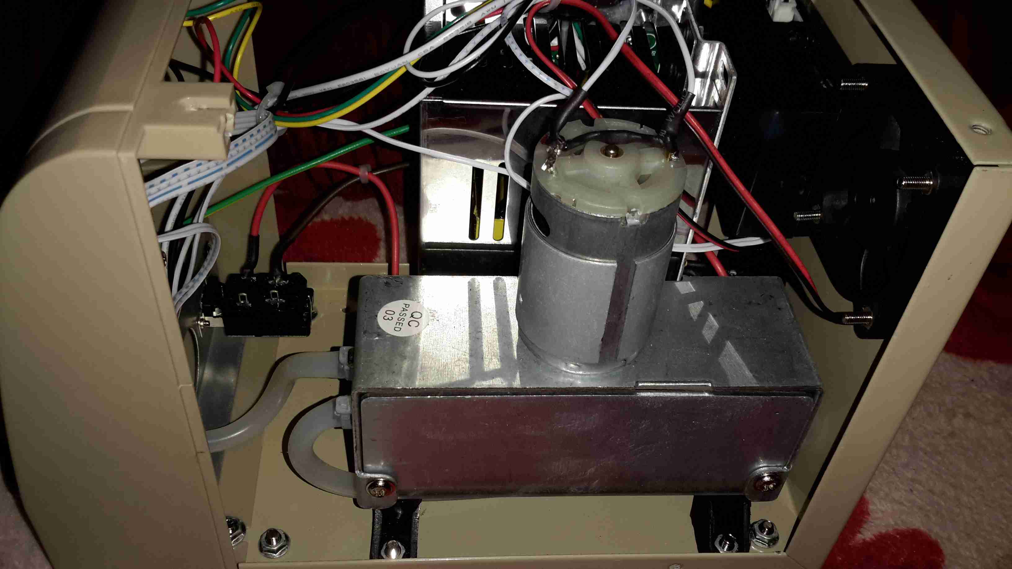
Compressor Internals
Removing a couple of screws reveals the internal components. Nothing much unusual here, a DC diaphragm pump, pressure switch & outlet fittings. There’s also a thermal cutout fitted next to the motor for protection.
The pressure switch attached to the manifold trips at 1.5Bar, keeping the pressure to the brush pretty much constant.
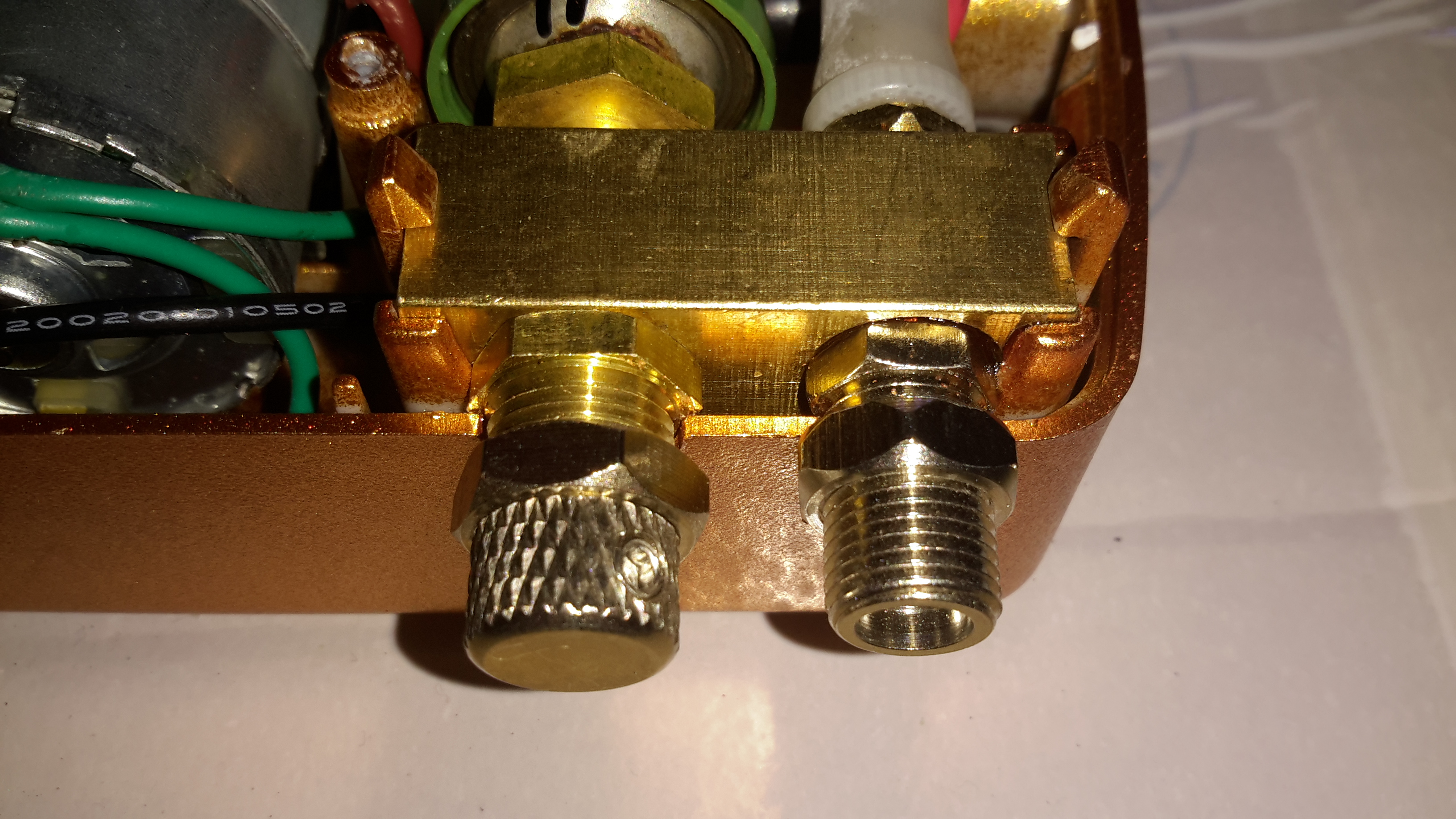
Air Block
Next to the air outlet fitting is an adjustment knob, supposedly for varying the pressure. However it’s just a piss-poorly designed adjustable relief valve that vents to atmosphere. There’s not much of a control range.
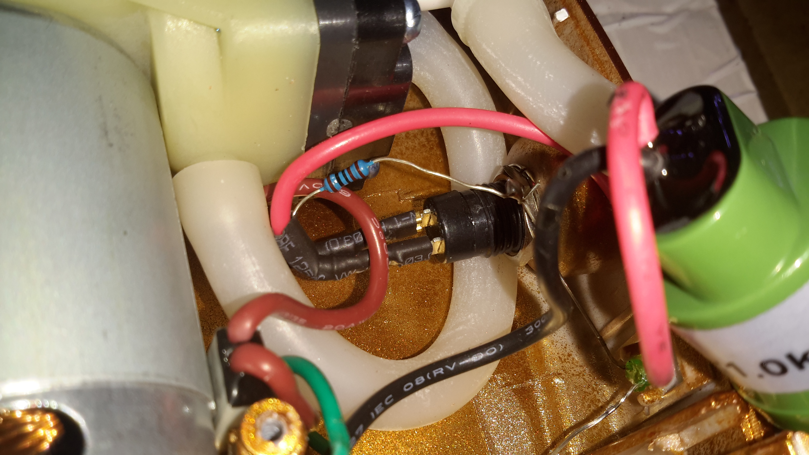
Messy Wiring
The wiring gets a bit messy where the power LED is concerned, with no heatshrink over the solder joints, but it’s adequate.
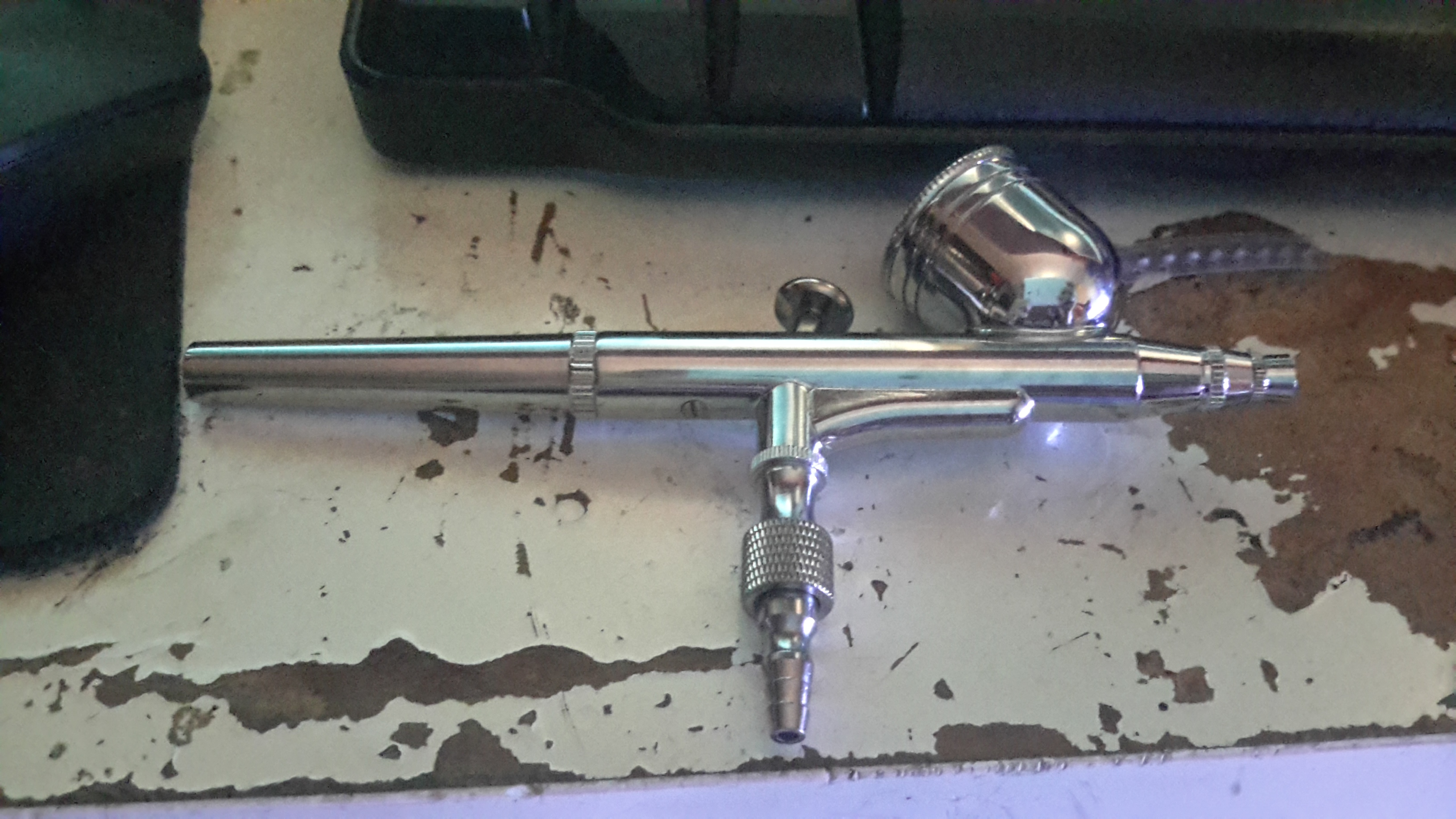
Airbrush
The airbrush itself isn’t too bad. It’s solid Brass, with a very nice Chrome finish. I’m not expecting miracles from a very cheap tool, but it certainly seems to be reasonable.
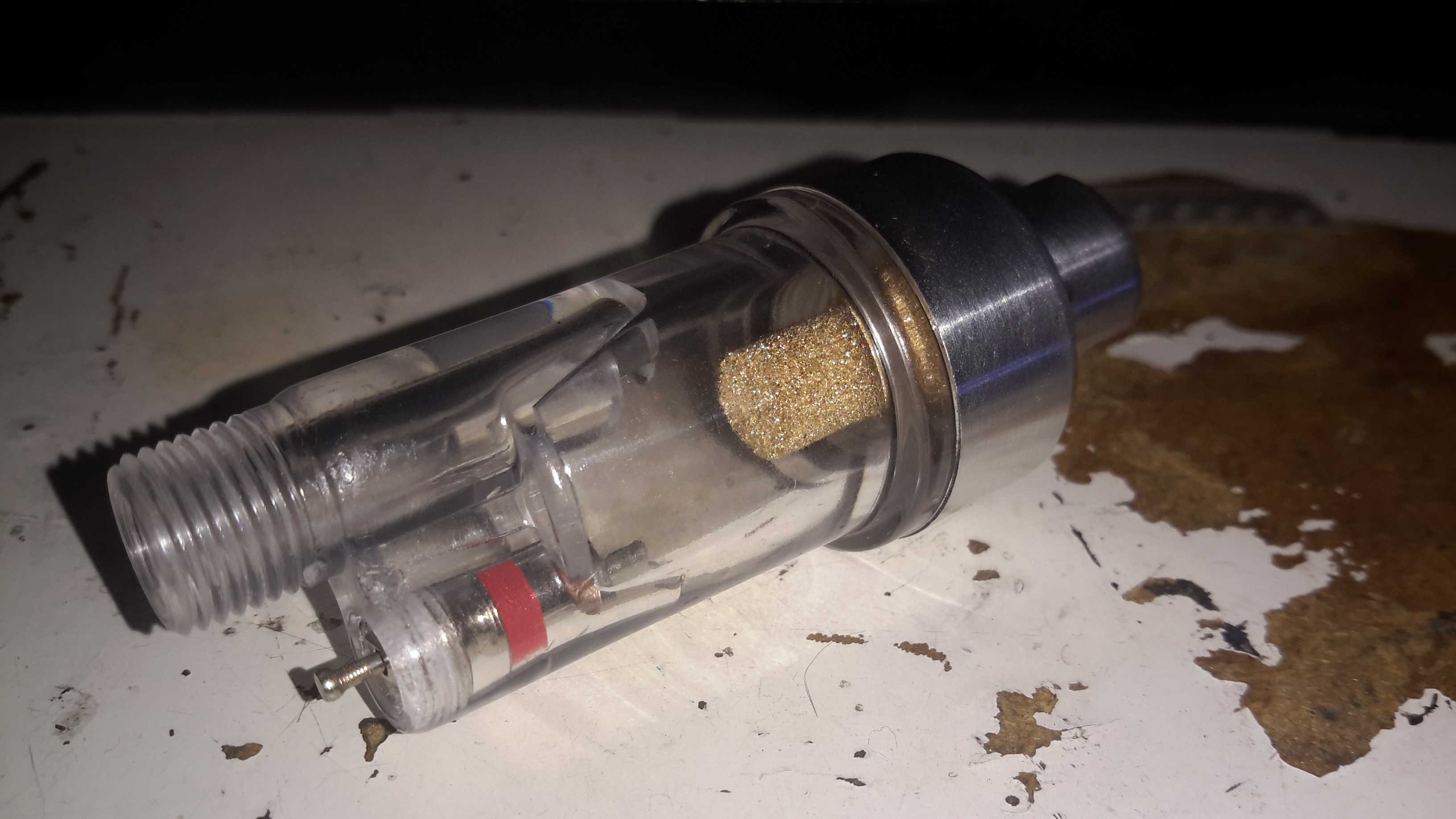
Water Trap
A moisture trap is supplied for the brush, to prevent water drops being sprayed out with the paint. Very handy.
For a long time I’ve needed a decent vacuum desoldering tool, as I do much stripping of old PCBs for random parts.
Solder wick works well for most things, but it’s expensive & can be fiddly. It also doesn’t keep very long as the copper braid oxidises & after that point it never seems to work particularly well, even when soaked in fresh flux.
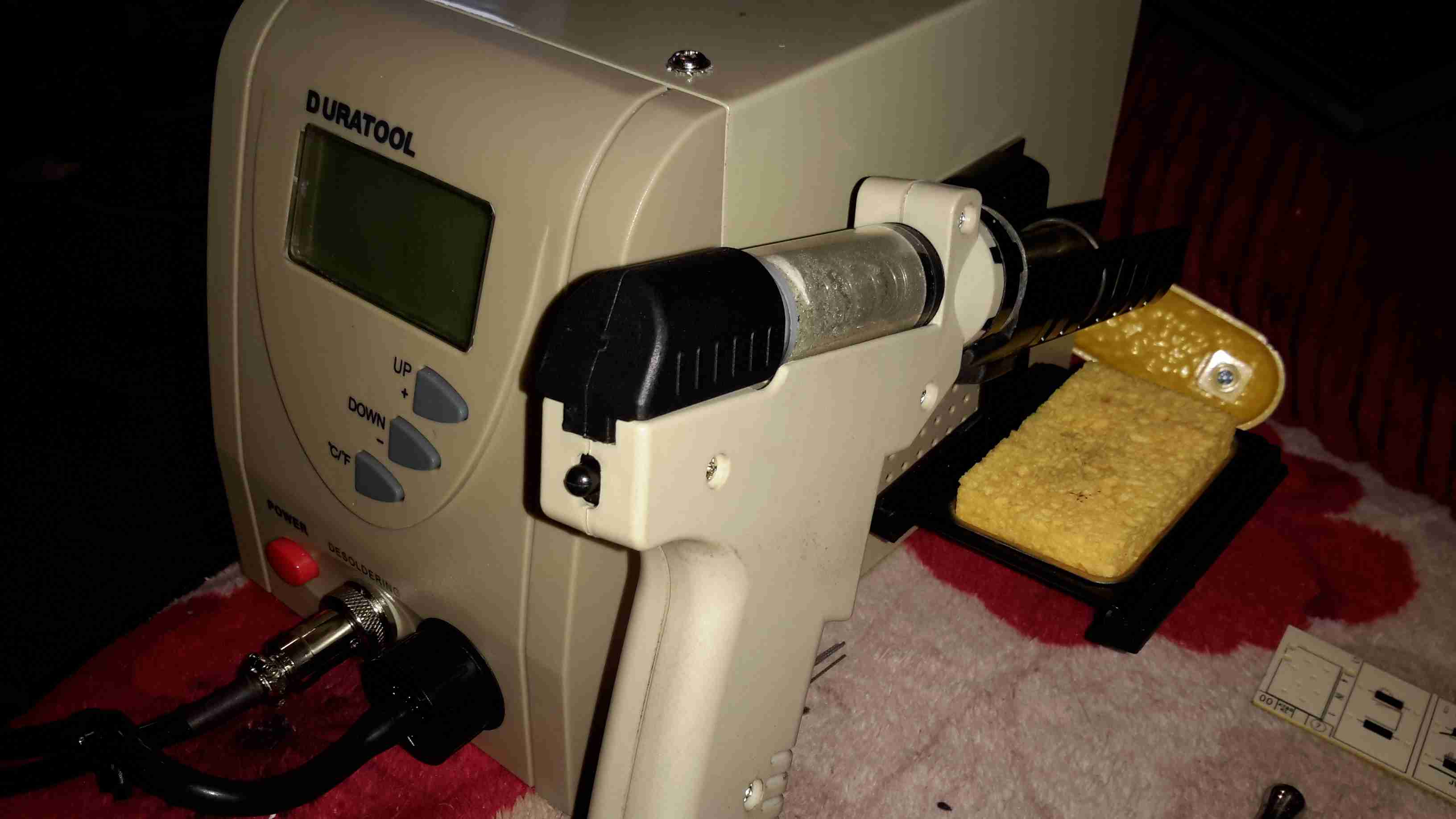
Desoldering Station
As usual eBay to the rescue! I managed to pick this one up for £80.
Vacuum Pump
Removing the lid reveals the internals. Front & centre is the vacuum pump, with the mains supply behind it. There’s also a very noisy cooling fan at the back. Not sure why since the unit never gets warm enough to actually warrant a fan.
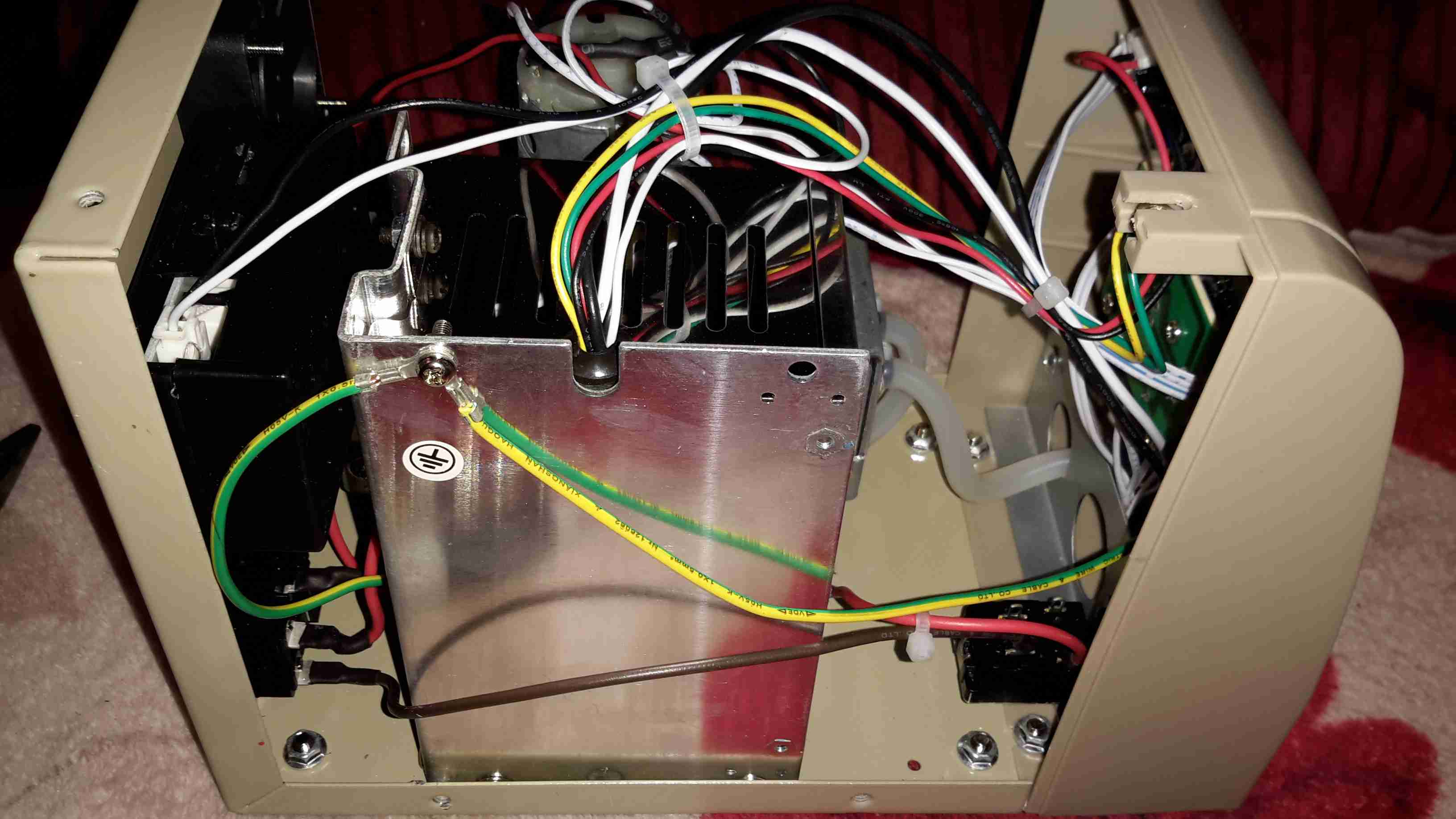
PSU
On the other side is the PSU. This is an 18v 12A rated SMPS, with a bit of custom electronics for controlling the iron element. Mounted to the back case is a small black box, more to come on this bit.
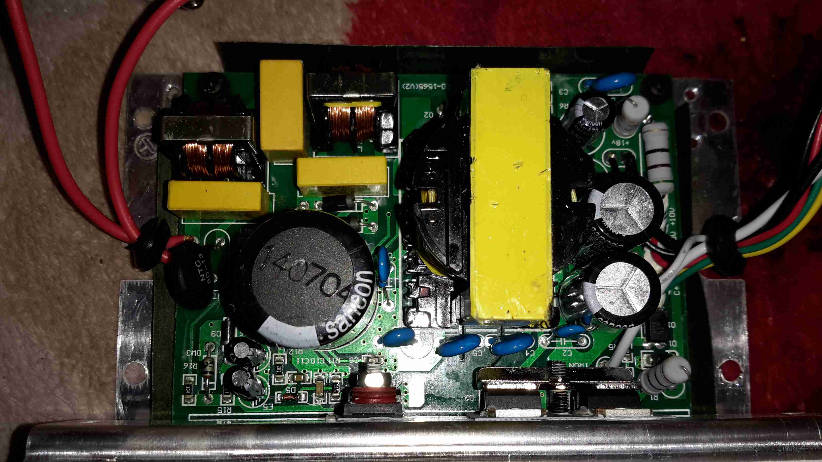
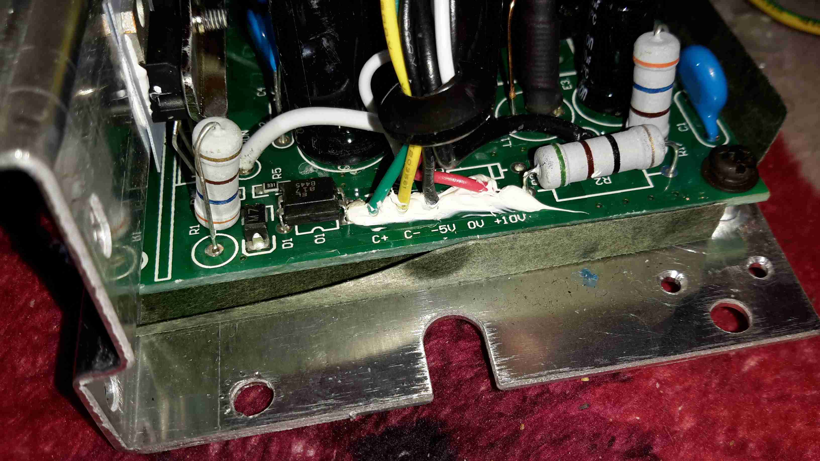
PSU Board
Cracking the case of the PSU reveals a pretty bog-standard SMPS, with a surprising amount of mains filtering for a Chinese supply. The DC outputs are on the right.
From the rail markings, this is clearly designed to output some more voltage rails – possibly for other models of unit. In this case though, a single 18v rail is present. The iron’s element connects directly to the supply, controlled via an opto-isolated MOSFET.
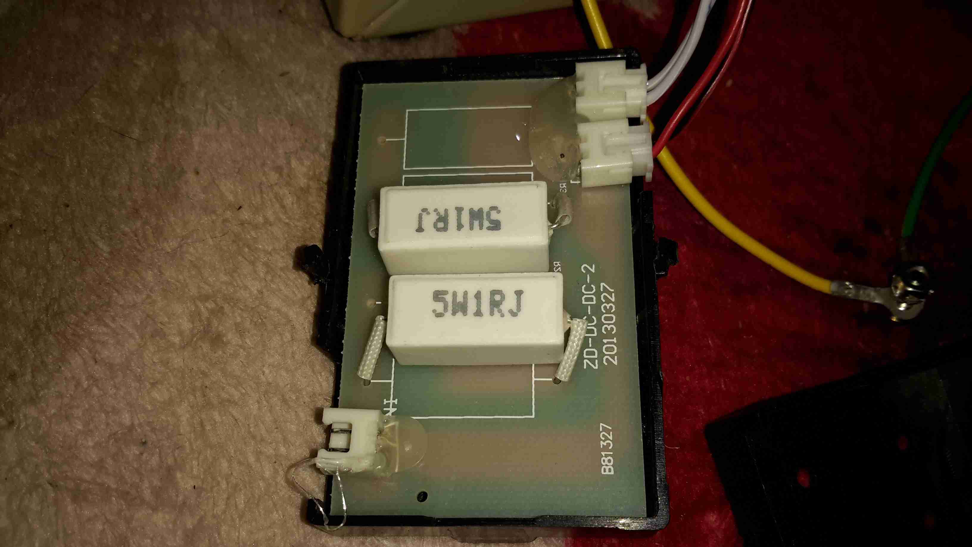
Chinese Voltage Regulation
As both the fan & the vacuum pump motor are 12v devices, some provision had to be made to reduce the 18v from the power supply to a more reasonable value. Inside the black plastic box are a pair of 1Ω 5W power resistors, connected in series. The output from this connects to the fan & vacuum pump. Because cheap, obviously.
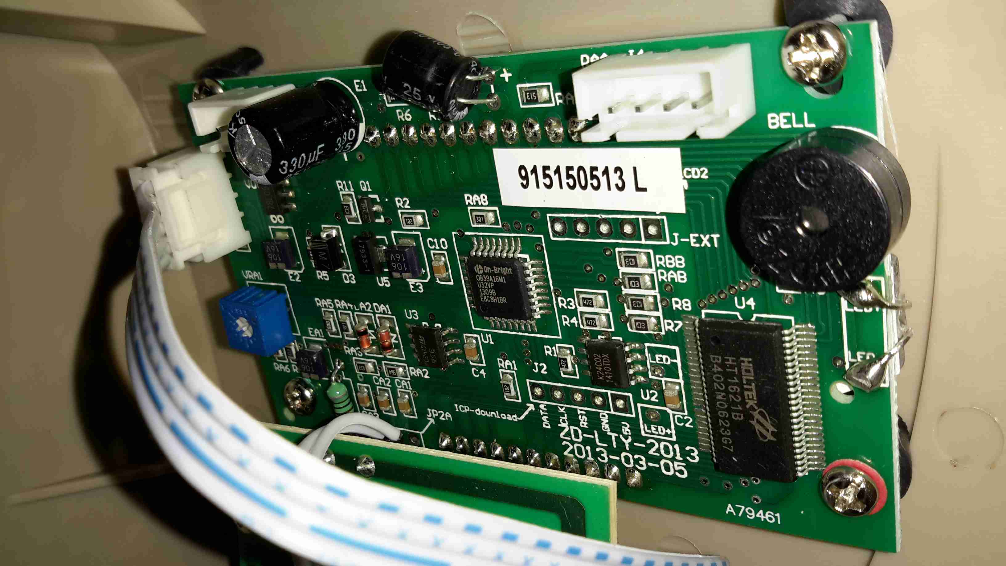
Controller
Finally, here’s the controller PCB, the main MCU is an 8081 derivative, with a Holtek HT1621B LCD controller for the front panel temperature readout. Iron temperature is achieved by a thermocouple embedded in the heater, I imagine the potentiometer on the left side of the PCB is for calibration.
As the crimp tool for the PSU connector in the Rigol scope is a very expensive piece of hardware, I decided to use pre-crimped terminals, from an ATX power connector. (They’re the same type).
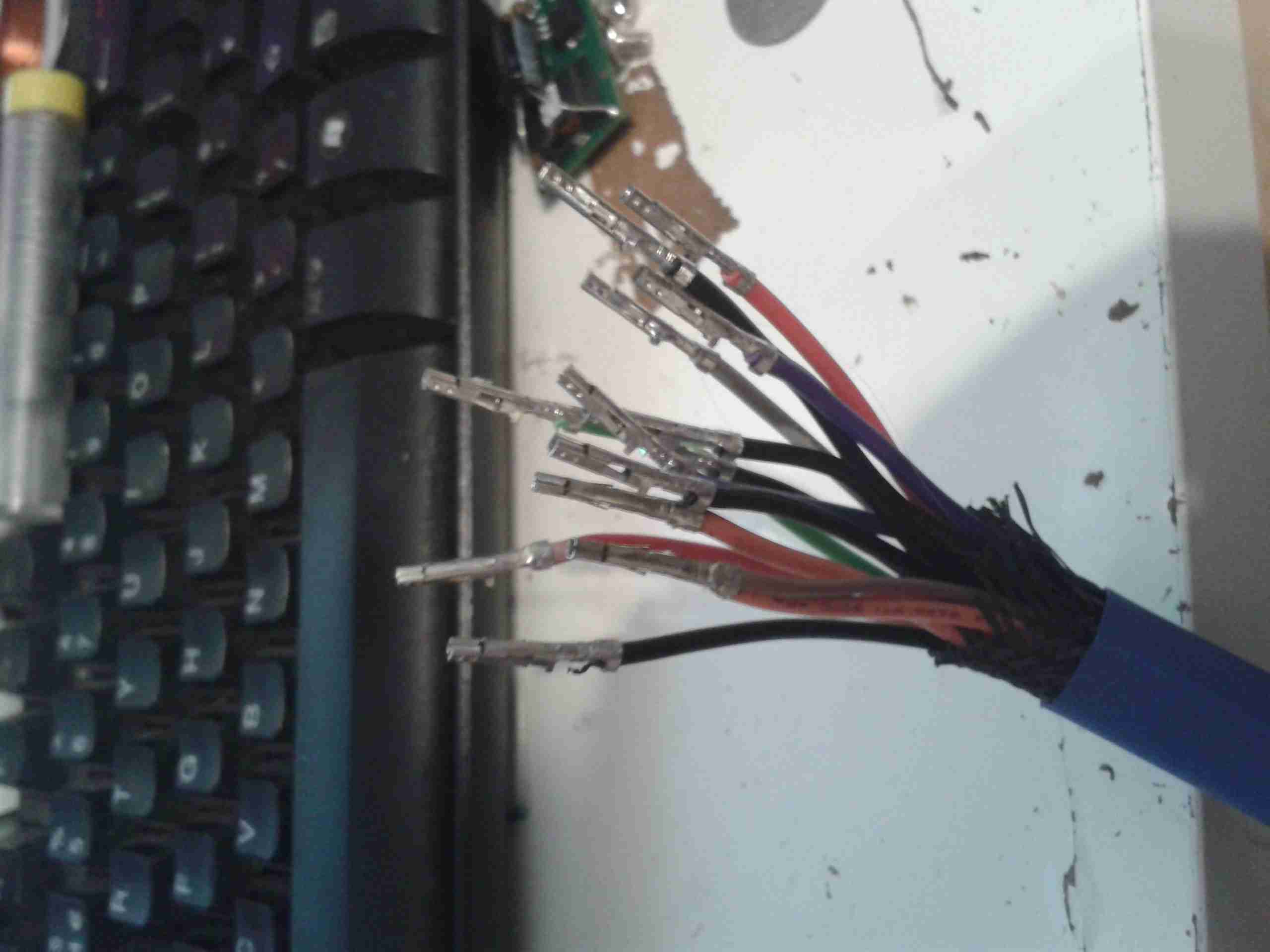
Wiring Loom
Here’s the partially completed loom, with the 13 cores for the power rails. The 14th pin is left out as that is for AC triggering, and this won’t be usable on a low voltage supply.
A couple of the pins have two wires, this is for voltage sensing at the connector to compensate for any voltage drop across the cable. The regulators I am using have provision for this feature.
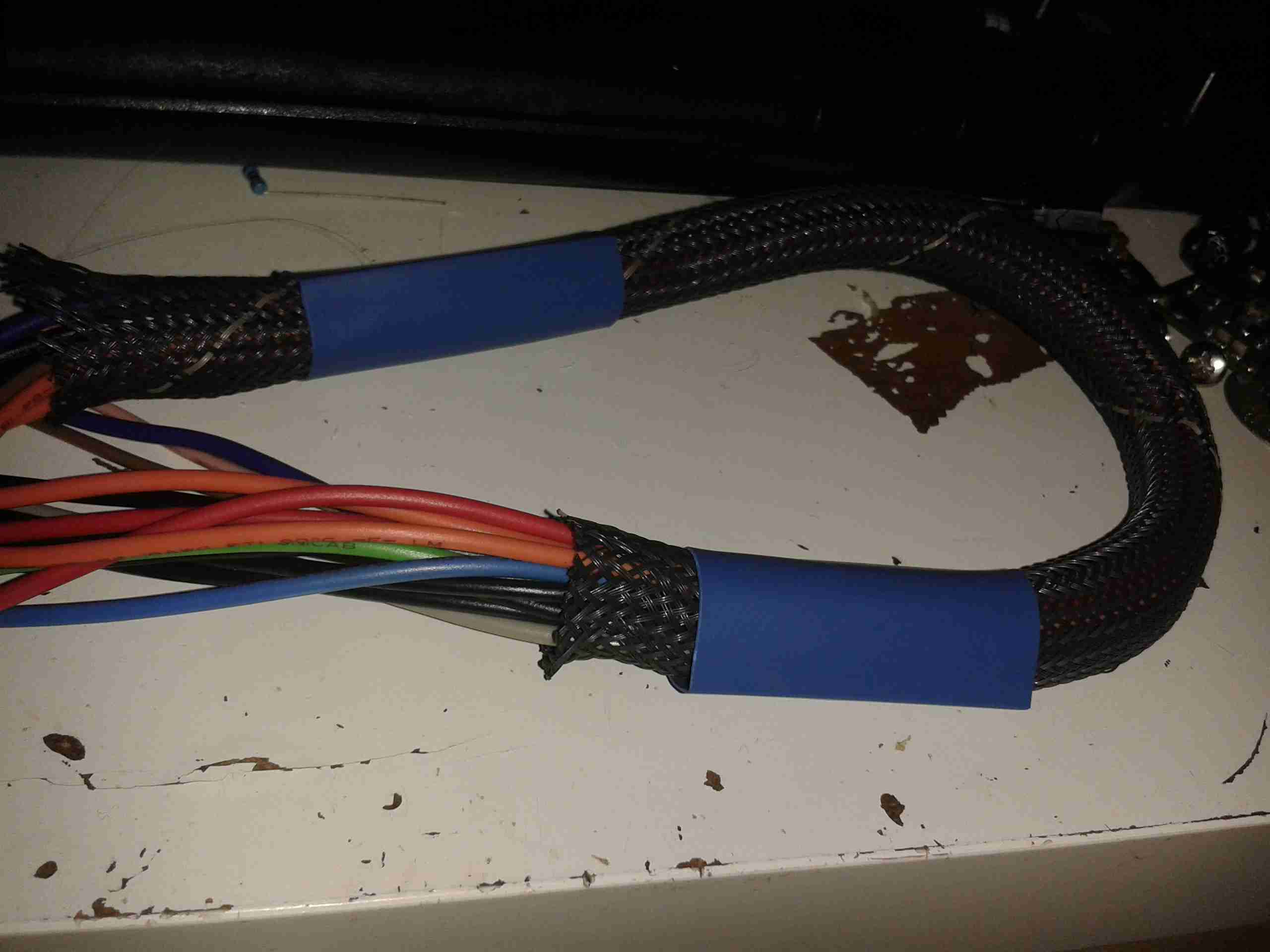
Sleeving
To keep the wiring tidy, I dug a piece of braided loom sleeving out of the parts bin, this will be finished off with the heatshrink once the pins are inserted into the connector shell.
The remaining parts for the loom have been ordered from Farnell & I expect delivery tomorrow.
Continuing from my previous post where I published an Eagle design layout for AD7C‘s Arduino powered VFO, here is a completed board.
I have made some alterations to the design since posting, which are reflected in the artwork download in that post, mainly due to Eagle having a slight psychotic episode making me ground one of the display control signals!
AD9850 VFO
The amplifier section is unpopulated & bypassed as I was getting some bad distortion effects from that section, some more work is needed there.
The Arduino Pro Mini is situated under the display, and the 5v rail is provided by the LM7805 on the lower left corner.
Current draw at 12v input is 150mA, for a power of 1.8W total. About 1W of this is dissipated in the LM7805 regulator, so I have also done a layout with an LM2574 Switching Regulator.
The SMPS version should draw a lot let power, as less is being dissipated in the power supply, but this version is more complex.
DDS VFO-SMPS
Here the SMPS circuit can be seen on the left hand side of the board, completely replacing the linear regulator.
I have not yet built this design, so I don’t know what kind of effect this will have on the output signal, versus the linear regulator. I have a feeling that the switching frequency of the LM2574 (52kHz) might produce some interference on the output of the DDS module. However I have designed this section to the standards in the datasheet, so this should be minimal.
Nevertheless this version is included in the Downloads section at the bottom of this post.
The output coupled through a 100nF capacitor is very clean, as can be seen below, outputting a 1kHz signal. Oscilloscope scale is 0.5ms/div & 1V/div.
VFO Output (Mucky ‘Scope)Scope Connected
Thanks again to Rich over at AD7C for the very useful tool design!
Linked below is the Eagle design files for this project, along with my libraries used to create it.
I bought one of these cheap HID kits from eBay to build a high-brightness work light that I could run from my central 12v supply.
At £14.99 I certainly wasn’t expecting anything more than the usual cheap Chinese construction. And that’s definitely what I got 😀
Potted PCB
The casing is screwed together with the cheapest of screws, with heads that are deformed enough to present a problem with removal.
As can be seen here, the inside of the unit is potted in rubber compound, mostly to provide moisture resistance, as these are for automotive use.
The ballast generates a 23kV pulse to strike the arc in the bulb, then supplies a steady 85v AC at 3A, 400Hz to maintain the discharge.
This module could quite easily be depotted as the silicone material used is fairly soft & can be removed with a pointed tool.
Hi-Lo Bulb Assembly
Here is the bulb removed from it’s mount. Under the bulb itself is a solenoid, which tilts the bulb by a few degrees, presumably to provide dim/dip operation for a headlight. This functionality is superfluous to my requirements.
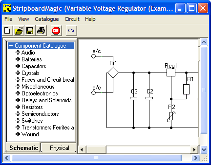
Stripboard Magic is a Windows application for designing PCB layouts on stripboard (aka prototyping board, aka Veroboard). It was released by a British company called Ambyr which ceased trading a long time ago.
The interface is a quite primitive and a little strange but the program is functional even on Windows XP. It also works great under wine in Linux, at least with version 0.9.38 and above as this is all I have checked. It should probably work on older versions too. I haven’t tried it on Vista though.
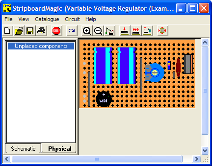
It can be a handy program when called upon and I have successfully used it a few times when throwing together random small circuits. Due to the interface I would imagine it to be a bit clumsy for very large circuits. The biggest gripe I have with it is the inability to change the orientation of components on the board, so some circuits tend to be slightly larger than they need to be.
I downloaded a copy of Stripboard Magic 1.0 back in the 90’s and recently just found it lying about on my computer. As I would consider it to well and truly be abandonware and as it seems to be a little sought after by some hobbyists I have provided a link to download it below.
[download id=”5624″]
Here are some screenshots showing the schematic view (top) and board layout view (bottom):
Stripboard Designer
Another hard to find app these days is Stripboard Designer, mirrored here for people who wish to use it.
Here we have a Dremel MultiPro rotary tool, a main powered 125W 33,000RPM bit of kit.
Motor Assembly
Here the field & controller assembly is removed from the casing.
Armature
Here is the armature, which rotates at up to 33,000RPM. The brushes rise against the commutator on the left, next to the bearing, the cooling fan is on the right hand side on the power output shaft, the chuck attaches at the far right end of the shaft.
Speed Controller & Brush Box
Here is the speed controller unit, inside is an SCR phase angle speed controller, to vary the speed of the motor from 10,000RPM to the full rated speed of 33,000RPM.
Mains Filter
This is the mains filter on the input to the unit, stops stray RF from the motor being radiated down the mains cable.
Tip Jar
If you’ve found my content useful, please consider leaving a donation by clicking the Tip Jar below!
All collected funds go towards new content & the costs of keeping the server online.