Posted on Leave a comment

Precision 10v & 5v Reference

After watching a video over at Scullcom Hobby Electronics on YouTube, I figured I’d build one of these precision references to calibrate my multimeters.

It’s based around a REF102P 10v precision reference & an INA105P precision unity gain differential amplifier.

For full information, check out the video, I won’t go into the details here, just my particular circuit & PCB layout.

In the video, Veroboard is used. I’m not too fond of the stuff personally. I find it far too easy to make mistakes & it never quite looks good enough. To this end I have spun a board in Eagle, as usual.

Precision Ref SCH
Precision Ref SCH – Click to Embiggen

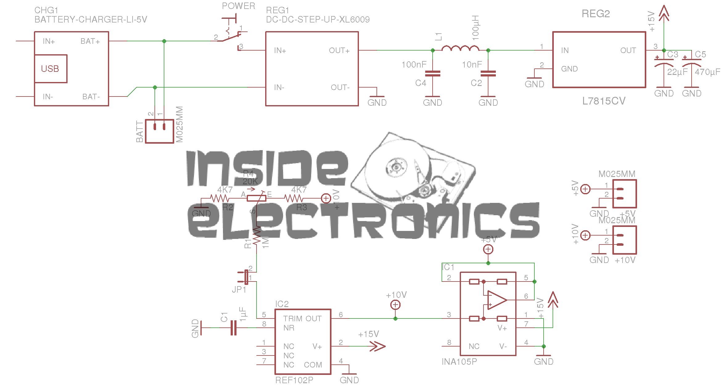
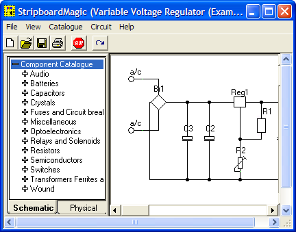
Here’s the schematic layout, the same as is in the video.

Precision Ref BRD
Precision Ref BRD

As usual, the Eagle CAD layout files can be found at the bottom of the post.

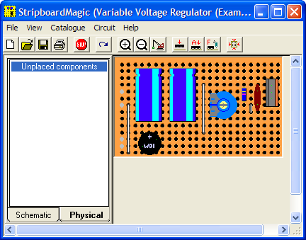
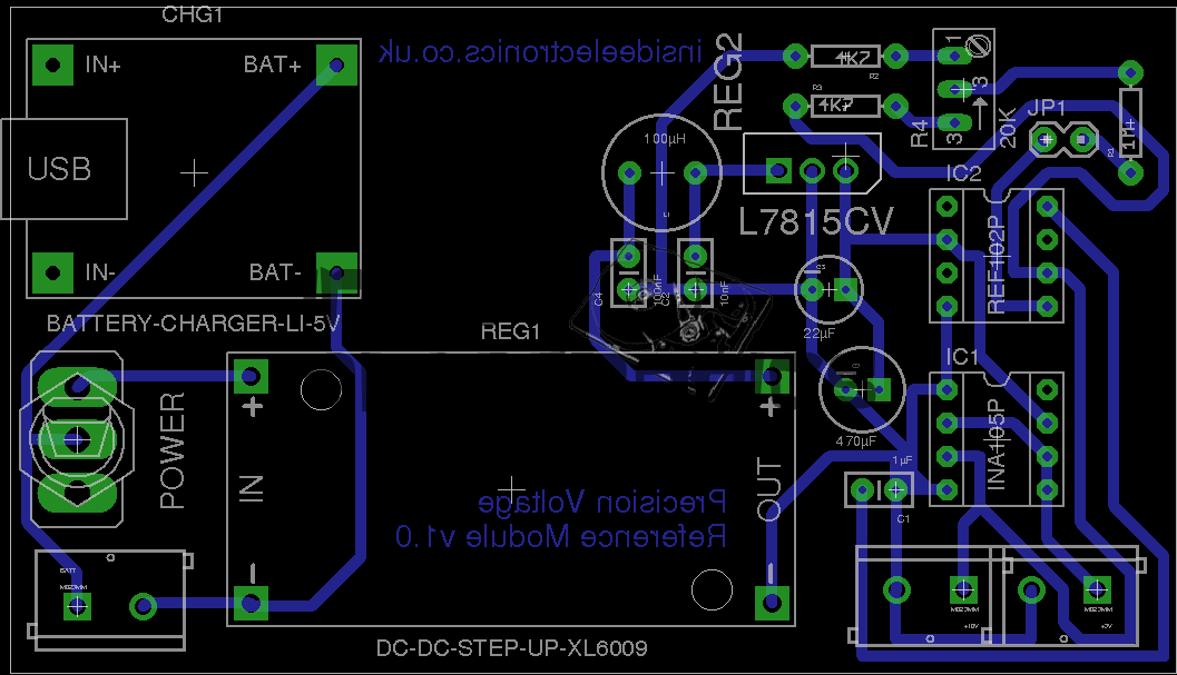
And the associated PCB layout. I have added the option to be able to tweak the output, to get a more accurate calibration, which can be added by connecting JP1 on the PCB.

As in the original build, this unit uses pre-built DC-DC converter & Li-Ion charger modules. A handy Eagle library can be found online for these parts.
I have however left off the battery monitor section of the circuit, since I plan to use a protected lithium cell for power. This also allowed me to keep the board size down, & use a single sided layout.

Toner Transfer Paper

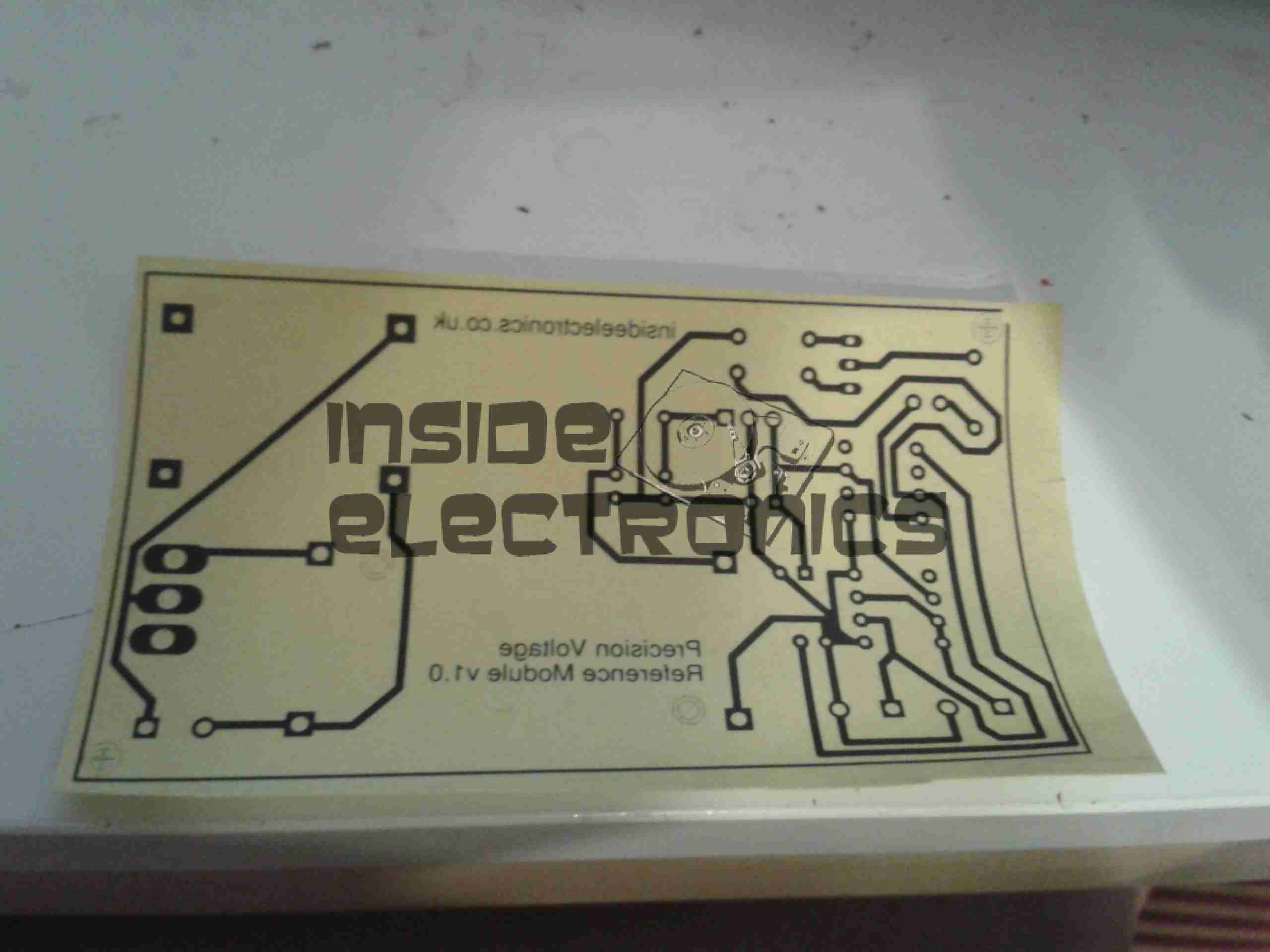
Here’s the track layout ready to iron onto the copper clad board. I use the popular toner transfer system with special paper from eBay, this stuff has a coating that allows the toner to easily be transferred to the PCB without having to mess about with soaking in water & scraping paper off.

Ironed On
Ironed On

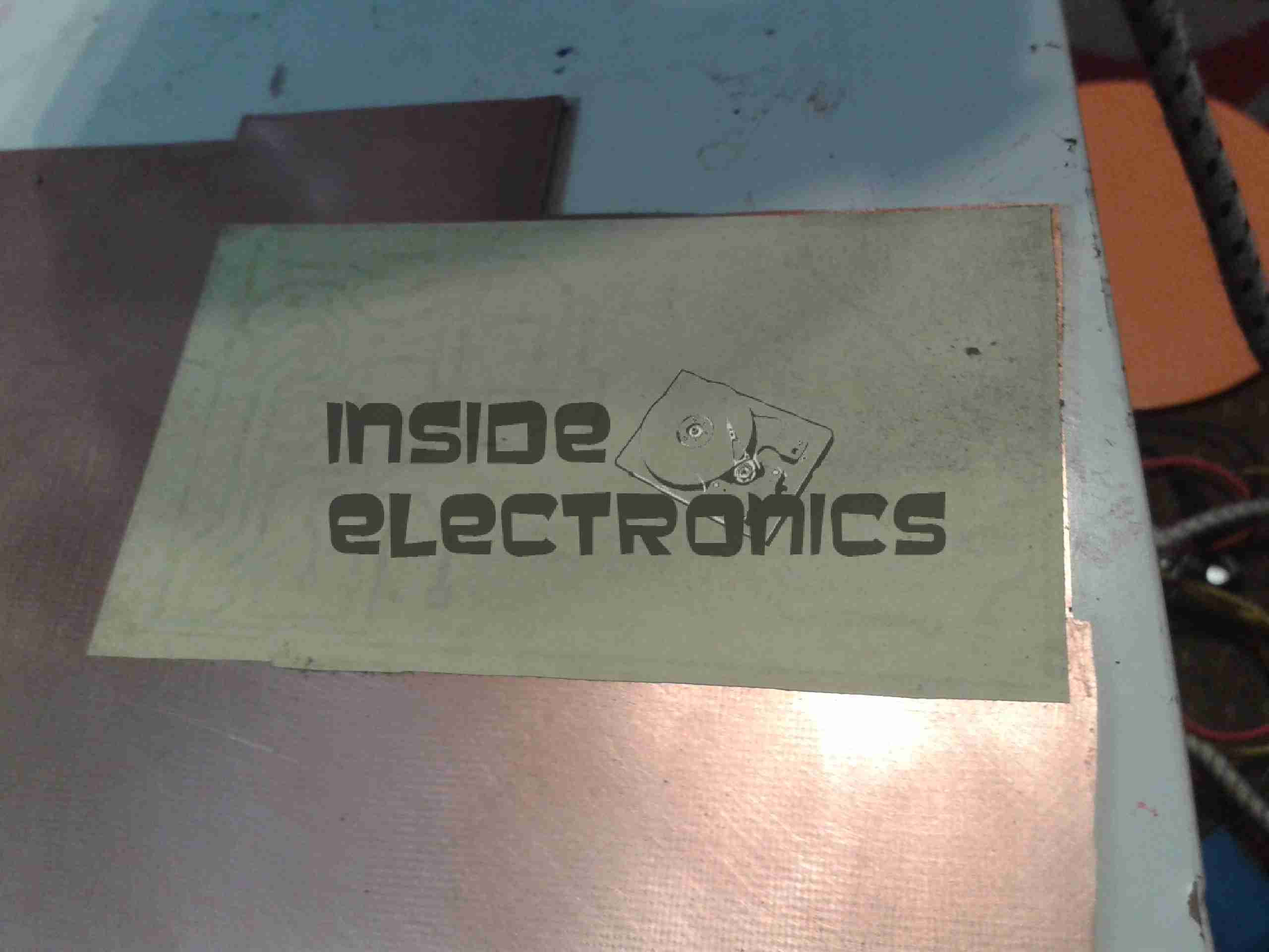
Here’s the paper having just been ironed onto the copper. After waiting for the board to cool off the paper is peeled off, leaving just the toner on the PCB.

Etched PCB
Etched PCB

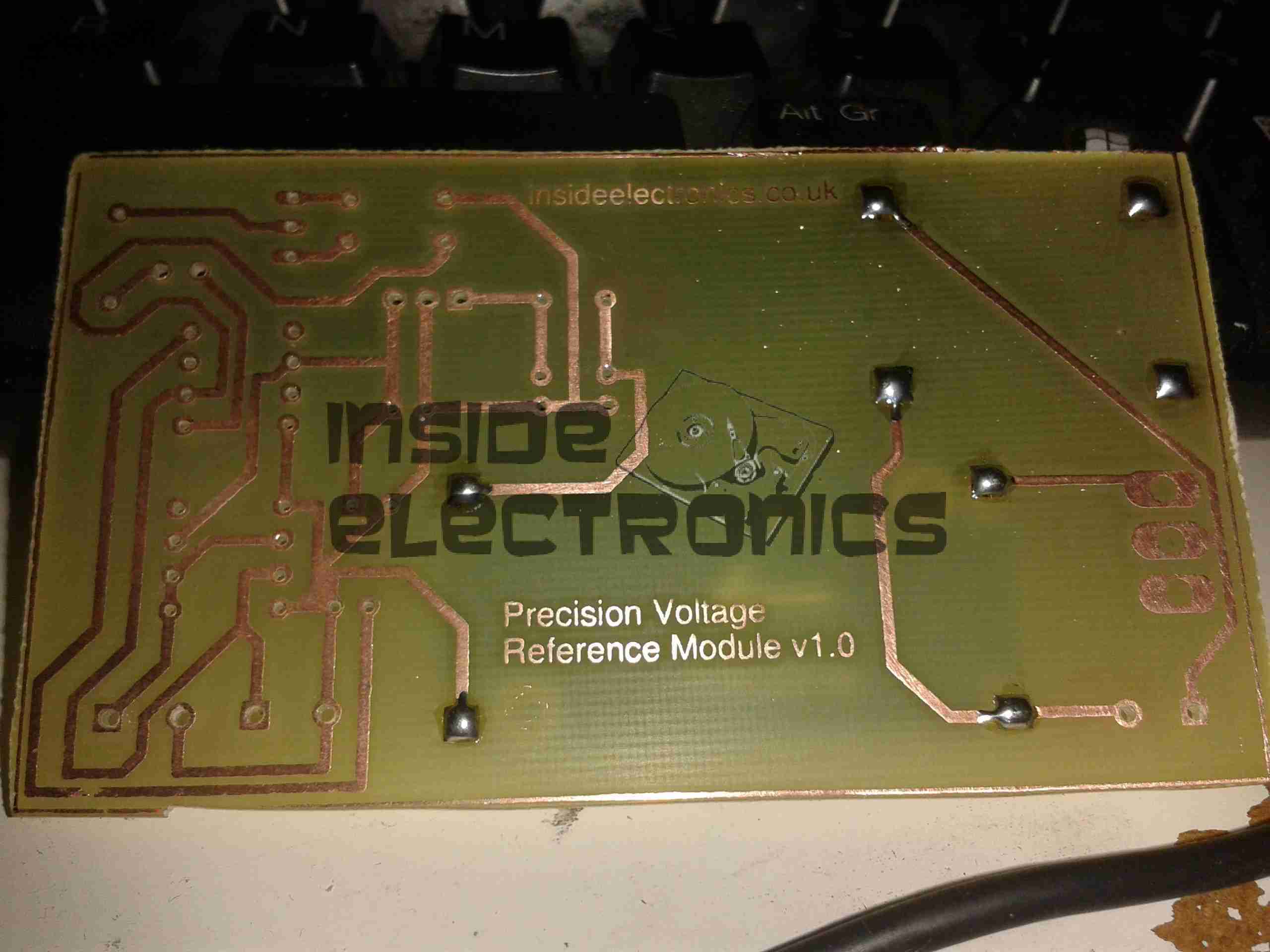
PCB just out of the etch tank, drilled & with the solder pins for the modules installed. Only one issue with the transfer, in the bottom left corner of the board is visible, a very small section of copper was over etched.
This is easily fixed with a small piece of wire.

Components Populated

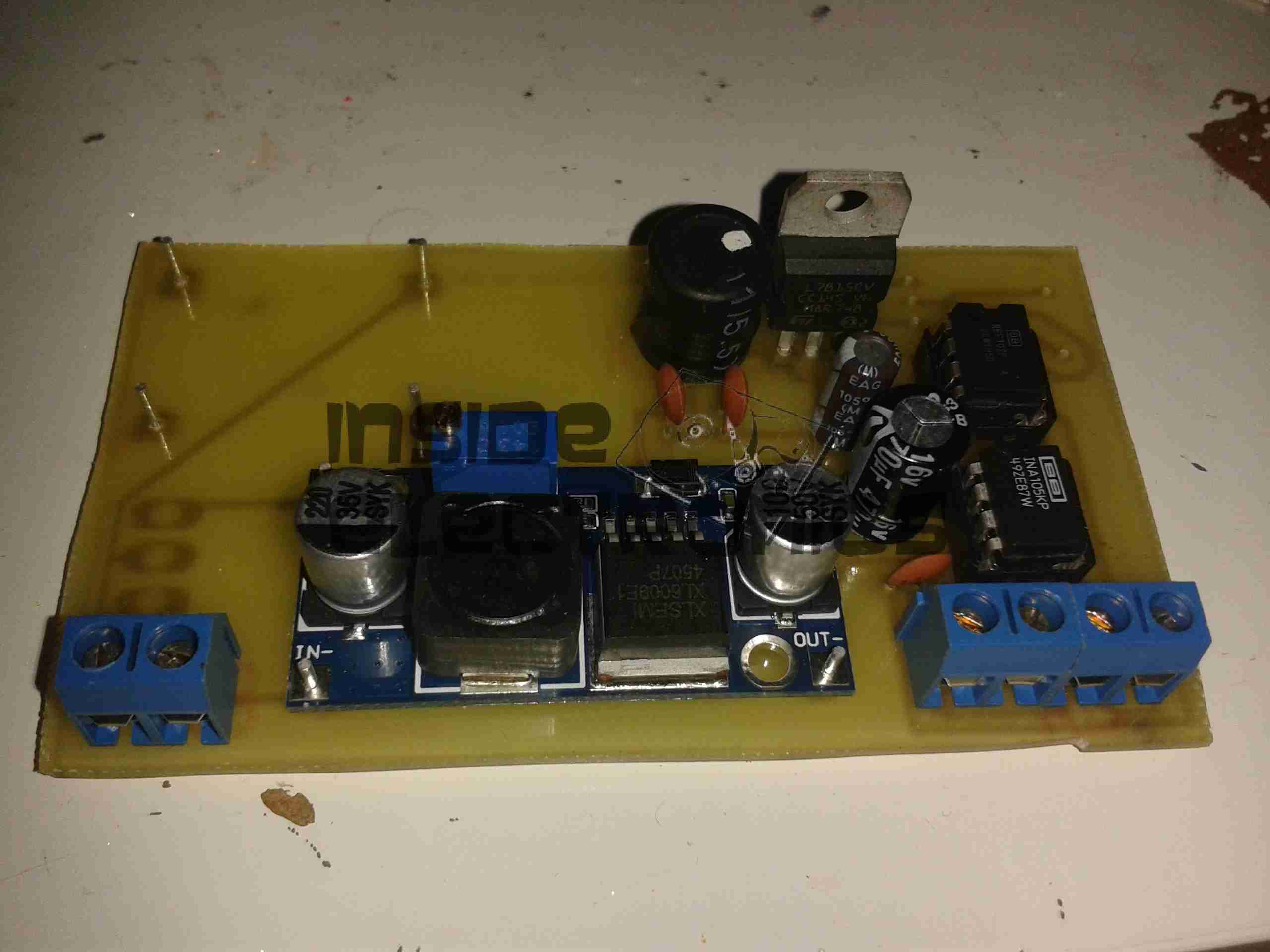
Main components populated. The DC-DC converter is set at 24v output, which the linear regulator then drops down to the +15v rail for the reference IC. The linear section of the regulator, along with the LC filter on the output of the switching regulator produce a low-ripple supply.

SMPS Ripple
SMPS Ripple

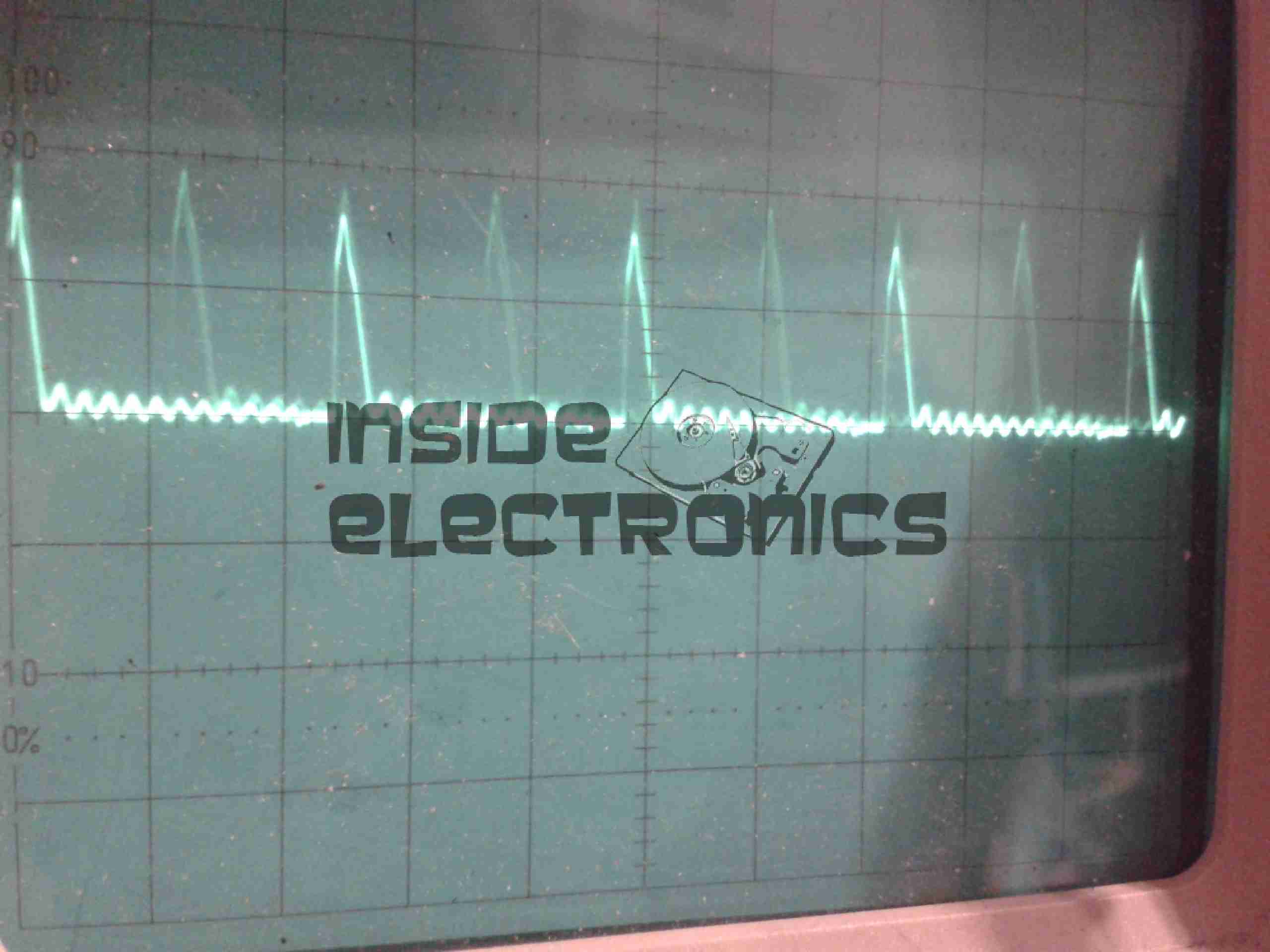
Here’s the scope reading the AC ripple on the output of the DC-DC converter. Scale is 100mV/Div. Roughly 150mV of ripple is riding on top of the DC rail.

Linear PSU Ripple
Linear PSU Ripple

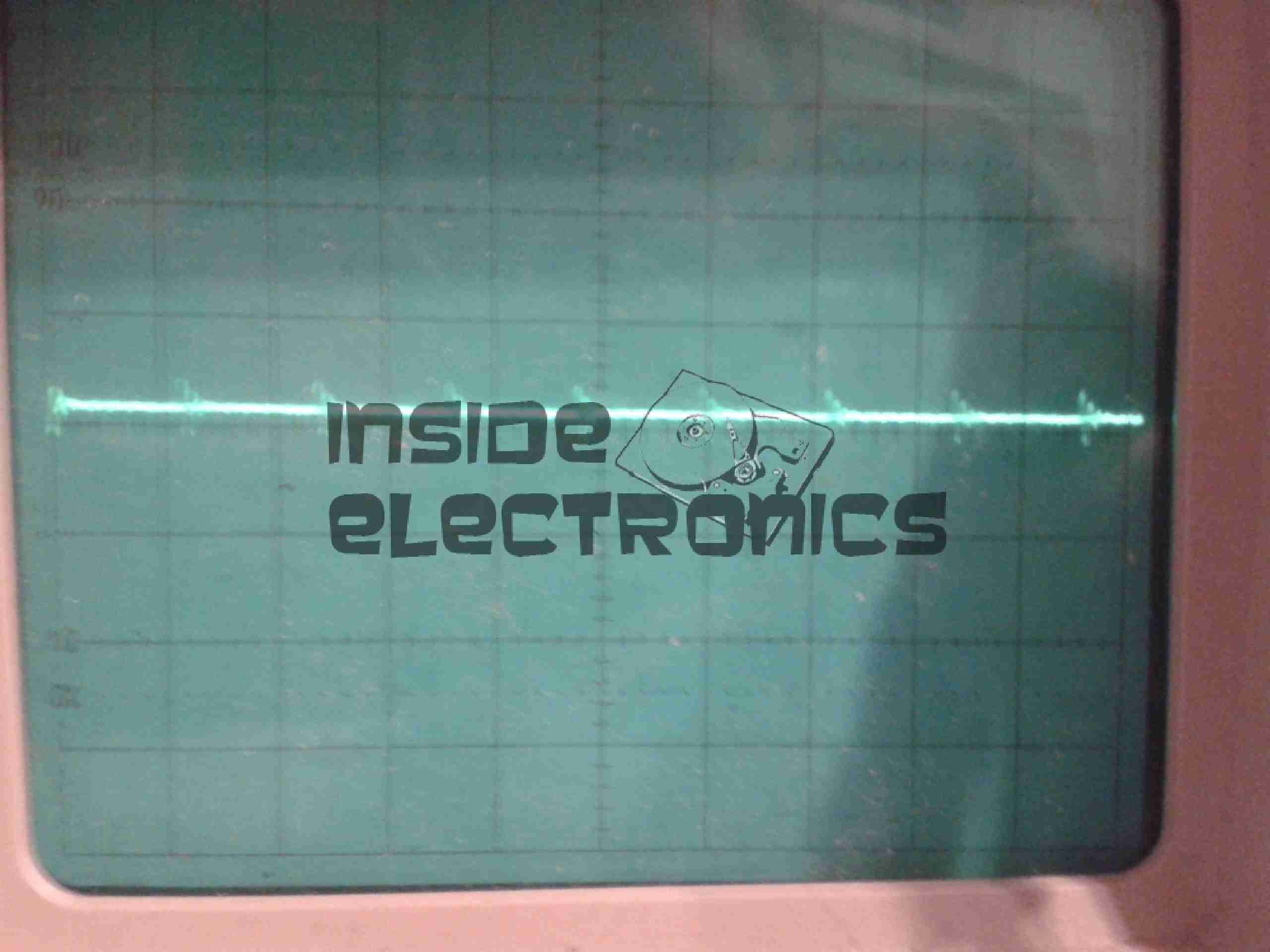
And here’s the output from the linear regulator, scale of 50mV/Div. Ripple has been reduced to ~15mV for the reference IC.
In total the circuit as built has a power consumption of ~0.5W, most of which is being dissipated as heat in the linear part of the PSU.

[download id=”5583″]

Posted on Leave a comment

4″ 7-Segment Display Driver

I was recently given some 4″ 7-Segment displays, Kingbright SC40-19EWA & of course, I needed to find a use for them.

I only have three, so a clock isn’t possible…

4" 7-Segment Display
4″ 7-Segment Display

As these displays are common cathode, & have a ~9v forward voltage on the main segments, some driver circuity is required to run multiplexed from an Arduino.

Driver Transistors
Driver Transistors

Driver circuit built on Veroboard, PNP segment transistors on the left, cathode NPN transistors in the centre, level-shifting NPN array on the right.

Base Bias Resistor Network

Base bias resistors on the back of the board to bias the bases of the segment drive transistors correctly.

Display Rear
Display Rear

Board soldered into the pins of the displays, which have been multiplexed.

Schematic to come along with some Arduino code to run a room thermometer, with an LM35 sensor

Posted on 5 Comments

Rare Veroboard Design Tools – Stripboard Magic

Stripboard Magic

Stripboard Magic is a Windows application for designing PCB layouts on stripboard (aka prototyping board, aka Veroboard). It was released by a British company called Ambyr which ceased trading a long time ago.

The interface is a quite primitive and a little strange but the program is functional even on Windows XP. It also works great under wine in Linux, at least with version 0.9.38 and above as this is all I have checked. It should probably work on older versions too. I haven’t tried it on Vista though.

It can be a handy program when called upon and I have successfully used it a few times when throwing together random small circuits. Due to the interface I would imagine it to be a bit clumsy for very large circuits. The biggest gripe I have with it is the inability to change the orientation of components on the board, so some circuits tend to be slightly larger than they need to be.

I downloaded a copy of Stripboard Magic 1.0 back in the 90’s and recently just found it lying about on my computer. As I would consider it to well and truly be abandonware and as it seems to be a little sought after by some hobbyists I have provided a link to download it below.

[download id=”5624″]

Here are some screenshots showing the schematic view (top) and board layout view (bottom):


Stripboard Designer

Another hard to find app these days is Stripboard Designer, mirrored here for people who wish to use it.

[download id=”5626″]

[download id=”5628″]