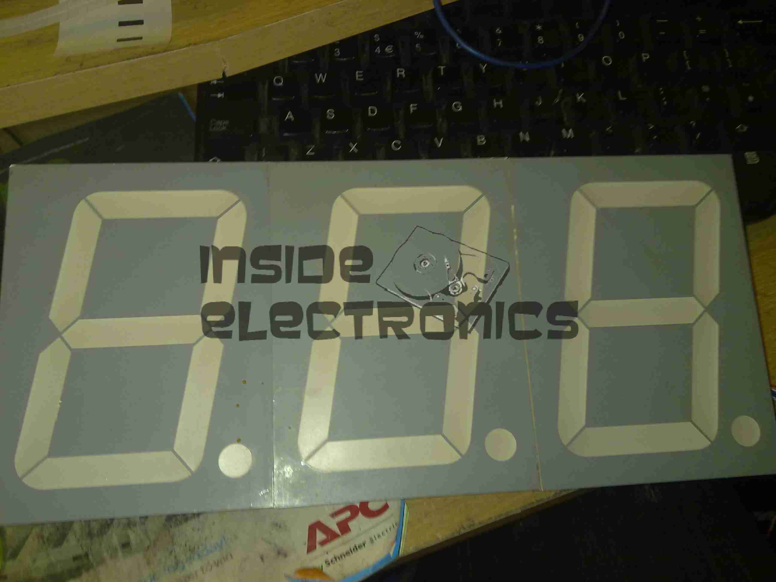
I was recently given some 4″ 7-Segment displays, Kingbright SC40-19EWA & of course, I needed to find a use for them.
I only have three, so a clock isn’t possible…
4″ 7-Segment Display
As these displays are common cathode, & have a ~9v forward voltage on the main segments, some driver circuity is required to run multiplexed from an Arduino.
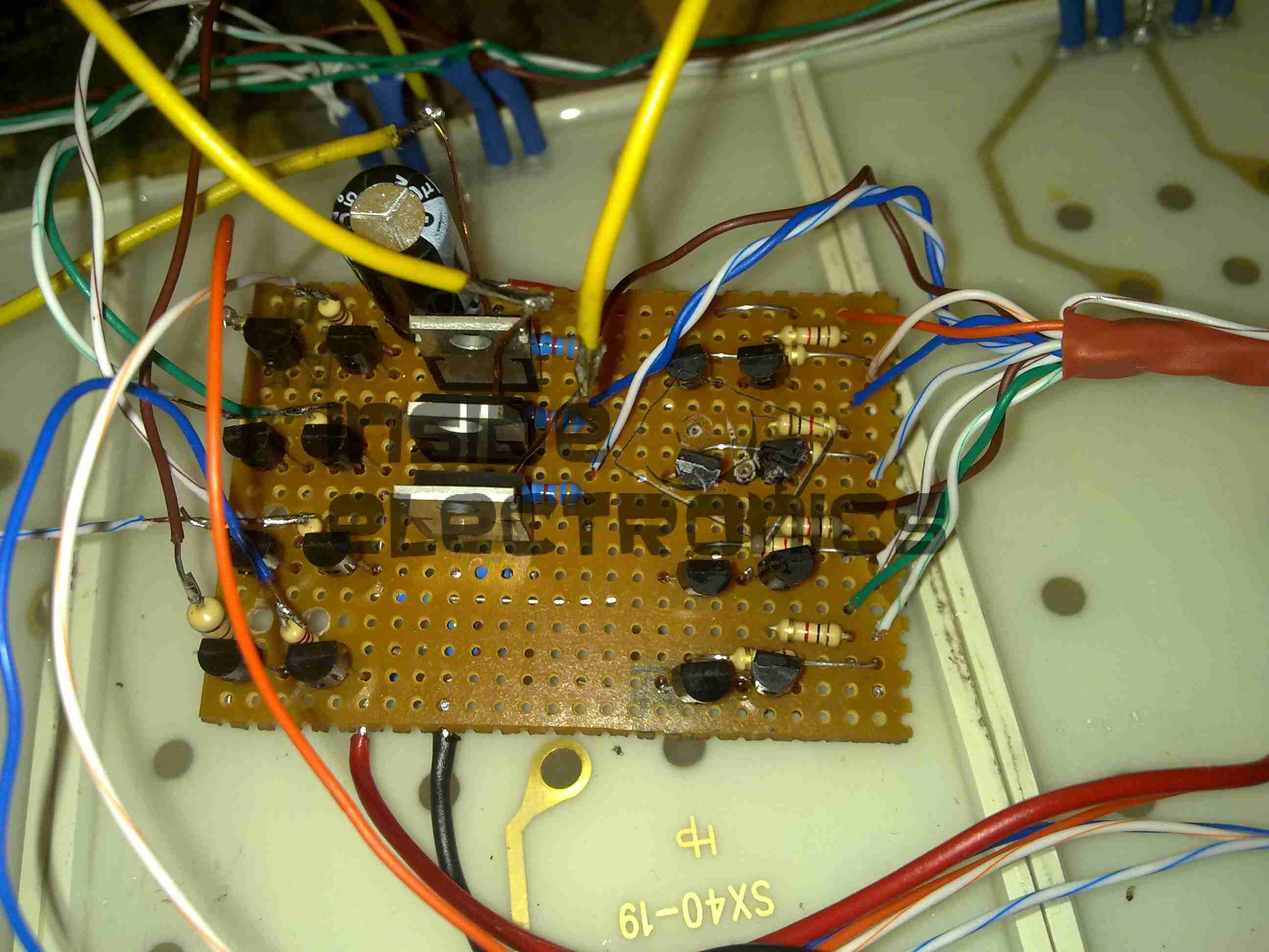
Driver Transistors
Driver circuit built on Veroboard, PNP segment transistors on the left, cathode NPN transistors in the centre, level-shifting NPN array on the right.
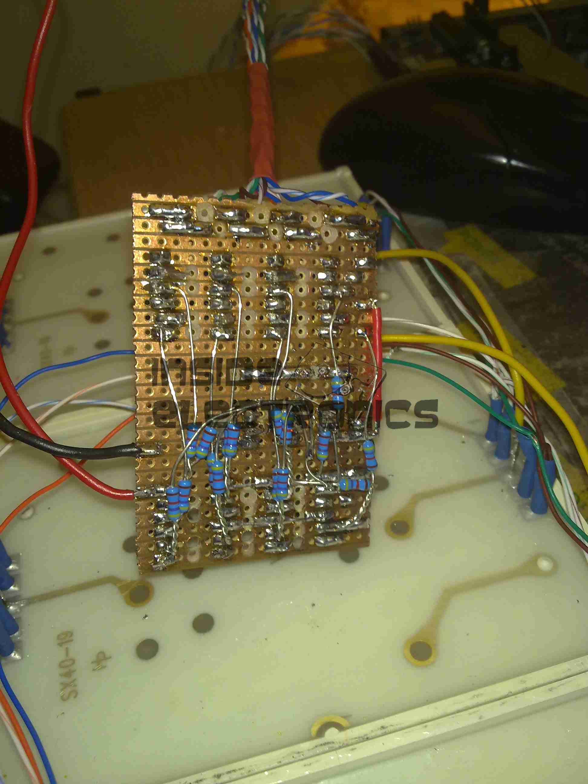
Base Bias Resistor Network
Base bias resistors on the back of the board to bias the bases of the segment drive transistors correctly.
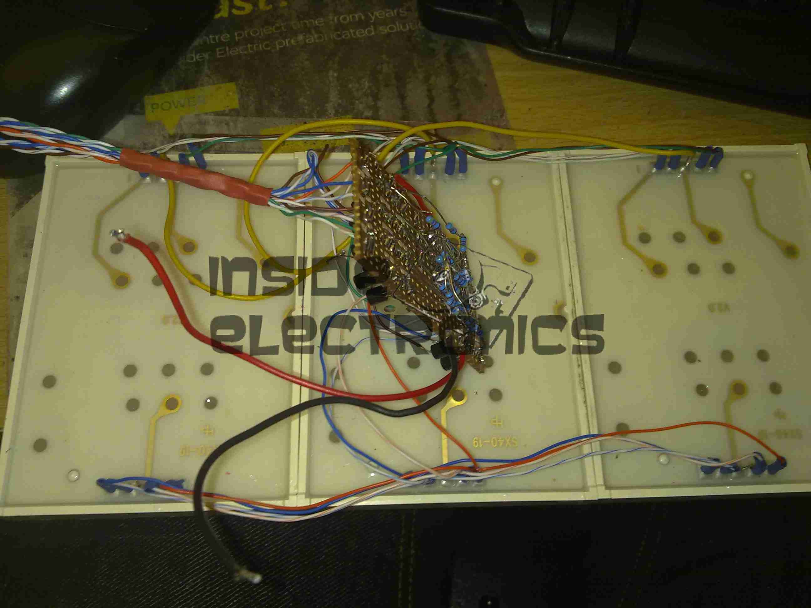
Display Rear
Board soldered into the pins of the displays, which have been multiplexed.
Schematic to come along with some Arduino code to run a room thermometer, with an LM35 sensor
This is a late 90’s business timeclock, used for maintaining records of staff working times, by printing the time when used on a sheet of card.
Front Internal
Here is the top cover removed, which is normally locked in place to stop tampering. The unit is programmed with the 3 buttons & the row of DIP switches along the top edge.
Instructions
Closeup of the settings panel, with all the various DIP switch options.
CPU & Display
Cover plate removed from the top, showing the LCD & CPU board, the backup battery normally fits behind this. The CPU is a 4-bit microcontroller from NEC, with built in LCD driver.
PSU & Drivers
Power Supply & prinhead drivers. This board is fitted with several NPN Darlington transistor arrays for driving the dox matrix printhead.
Printhead
Printhead assembly itself. The print ribbon fits over the top of the head & over the pins at the bottom. The drive hammers & solenoids are housed in the circular top of the unit.
Printhead Bottom
Bottom of the print head showing the row of impact pins used to create the printout.
Bottom of the solenoid assembly with the ribbon cable for power. There are 9 solenoids, to operate the 9 pins in the head.
Return Spring
Top layer of the printhead assembly, showing the leaf spring used to hold the hammers in the correct positions.
Hammers
Hammer assembly. The fingers on the ends of the arms push on the pins to strike through the ribbon onto the card.
Solenoids
The ring of solenoids at the centre of the assembly. These are driven with 3A darlington power arrays on the PSU board.
Gearbox Internals
There is only a single drive motor in the entire unit, that both clamps the card for printing & moves the printhead laterally across the card. Through a rack & pinion this also advances the ribbon with each print.
Tip Jar
If you’ve found my content useful, please consider leaving a donation by clicking the Tip Jar below!
All collected funds go towards new content & the costs of keeping the server online.