Posted on Leave a comment

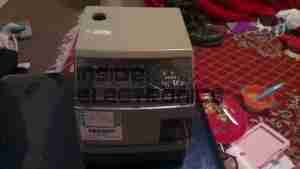
Amano PIX 3000x Timeclock

Front
Front

This is a late 90’s business timeclock, used for maintaining records of staff working times, by printing the time when used on a sheet of card.
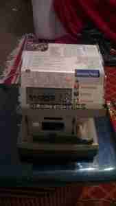
Front Internal
Front Internal

Here is the top cover removed, which is normally locked in place to stop tampering. The unit is programmed with the 3 buttons & the row of DIP switches along the top edge.
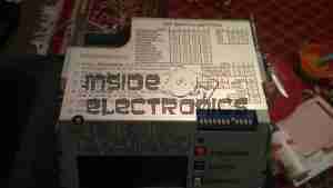
Instructions
Instructions

Closeup of the settings panel, with all the various DIP switch options.
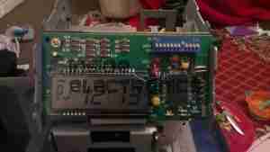
CPU & Display
CPU & Display

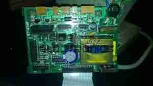
Cover plate removed from the top, showing the LCD & CPU board, the backup battery normally fits behind this. The CPU is a 4-bit microcontroller from NEC, with built in LCD driver.
PSU & Drivers
PSU & Drivers

Power Supply & prinhead drivers. This board is fitted with several NPN Darlington transistor arrays for driving the dox matrix printhead.
Printhead
Printhead

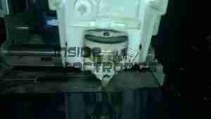
Printhead assembly itself. The print ribbon fits over the top of the head & over the pins at the bottom. The drive hammers & solenoids are housed in the circular top of the unit.
Printhead Bottom
Printhead Bottom

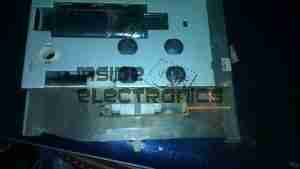
Bottom of the print head showing the row of impact pins used to create the printout.

2013-02-13 18.00.09Bottom of the solenoid assembly with the ribbon cable for power. There are 9 solenoids, to operate the 9 pins in the head.
Return Spring
Return Spring

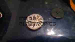
Top layer of the printhead assembly, showing the leaf spring used to hold the hammers in the correct positions.
Hammers
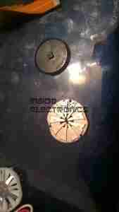
Hammers

Hammer assembly. The fingers on the ends of the arms push on the pins to strike through the ribbon onto the card.

Solenoids
Solenoids

The ring of solenoids at the centre of the assembly. These are driven with 3A darlington power arrays on the PSU board.
Gearbox Internals
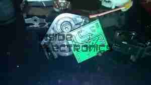
Gearbox Internals

There is only a single drive motor in the entire unit, that both clamps the card for printing & moves the printhead laterally across the card. Through a rack & pinion this also advances the ribbon with each print.


Posted on 10 Comments

Camcorder CRT Viewfinder

CRT Assembly
CRT Assembly

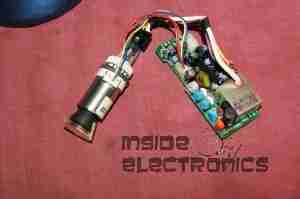
Here are the viewfinder electronics from a 1984 Hitachi VHS Movie VM-1200E Camcorder. These small CRT based displays accept composite video as input, plus 5-12v DC for power.

Screen
Screen

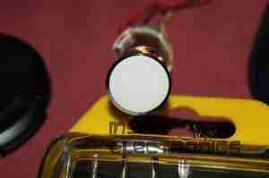
Here is the front face of the CRT, diameter is 0.5″.

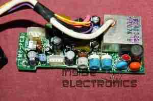
Power Board
Power Board

Closeup view of the PCB, there are several adjustments & a pair of connectors. Socket in the upper left corner is the power/video input. Pinout is as follows:

  1. Brown – GND
  2. Red – Video Input
  3. Orange – +12v DC
  4. Yellow – Record LED
The potentiometers on the PCB from left:
  1. H. ADJ
  2. V. ADJ
  3. BRIGHT
  4. FOCUS
PCB Part Number reads: EM6-PCB
This unit utilises the BA7125L deflection IC.
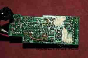
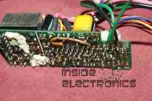
Solderside
Solderside
Reverse side of the PCB, very few SMT components on this board.
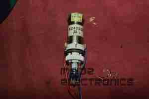
Tube Assembly
Tube Assembly
Here is an overall view of the CRT assembly with scan coils. Tube model is NEC C1M52P45.
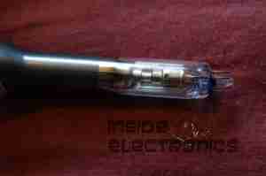
Electron Gun
Electron Gun

Closeup view of the CRT neck, showing the electron gun assembly.


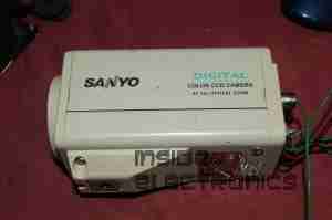
CCTV Camera
CCTV Camera

The old CCTV camera used to feed a composite signal to the CRT board. Sanyo VCC-ZM300P.

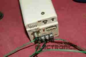
CCTV Camera Connections

Connections at the back of the camera. Red & Black pair of wires lead to 12v power supply, Green & Black pair lead to the CRT board’s power pins. Seperate green wire is pushed into the BNC video connector for the video feed. video ground is provided by the PSU’s ground connection.

Connections
Connections

Finally the connections at the CRT drive board, left to right, +12v, Video, GND.

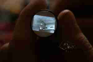
Screen Operation
Screen Operation

Display taking video signal from the CCTV camera.