Posted on Leave a comment

Another Viewfinder CRT

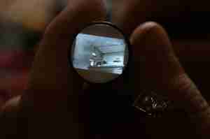
Here’s another viewfinder CRT, removed from a 1980’s vintage VHS camera I managed to get cheap from eBay.

This unit is very similar to the last one I posted about, although there are a few small differences in the control circuitry.

Viewfinder Schematic
Viewfinder Schematic – Click to Embiggen

Here’s the schematic, showing all the functional blocks of the viewfinder circuitry. An integrated viewfinder IC is used, which generates all the required scan waveforms for the CRT.
On the left is the input connector, with the power & video signals. Only pins 2 (GND), 3 (Composite video), & 4 (+8v) are needed here. Pin 1 outputs a horizontal sync signal for use elsewhere in the camera, while pin 5 fed the recording indicator LED.

To make connection easier,  I have rearranged the wires in the input connector to a more understandable colour scheme:
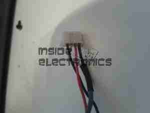
Input Connector
Input Connector

Red & Blue for power input, & a coax for the video. For the video GND connection, I have repurposed the Rec. LED input pin, putting a shorting link across where the LED would go to create a link to signal ground. Keeping this separate from the power GND connection reduces noise on the CRT.
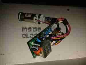
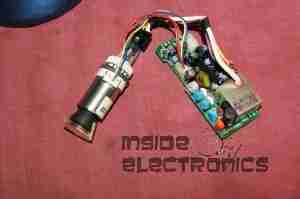
Viewfinder CRT Assembly

Here’s the complete assembly liberated from it’s plastic enclosure.
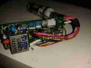
PCB Closeup
PCB Closeup

Closeup of the control PCB. The 3 potentiometers control the CRT brightness, focus & vertical size.
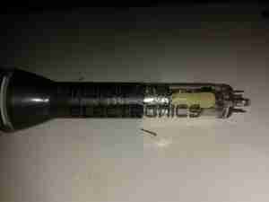
M01KGG007WB CRT
M01KGG007WB CRT

The tiny CRT. Only ~60mm in length, with an 18mm screen size. This tube runs on +2294v final anode voltage. Much higher than I expected.
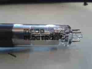
Electron Gun Closeup

The electron gun assembly, with the cathode, focus & final anode cups.
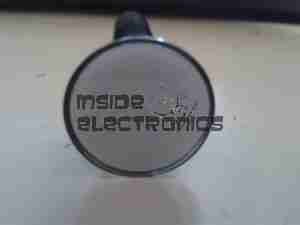
Phosphor Screen
Phosphor Screen

This screen is just a little bigger than a UK 5p piece! A marvel of precision engineering.
 

Posted on 10 Comments

Camcorder CRT Viewfinder

CRT Assembly
CRT Assembly

Here are the viewfinder electronics from a 1984 Hitachi VHS Movie VM-1200E Camcorder. These small CRT based displays accept composite video as input, plus 5-12v DC for power.

Screen
Screen

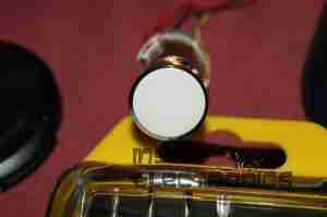
Here is the front face of the CRT, diameter is 0.5″.

Power Board
Power Board

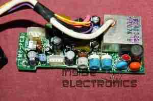
Closeup view of the PCB, there are several adjustments & a pair of connectors. Socket in the upper left corner is the power/video input. Pinout is as follows:

  1. Brown – GND
  2. Red – Video Input
  3. Orange – +12v DC
  4. Yellow – Record LED
The potentiometers on the PCB from left:
  1. H. ADJ
  2. V. ADJ
  3. BRIGHT
  4. FOCUS
PCB Part Number reads: EM6-PCB
This unit utilises the BA7125L deflection IC.
Solderside
Solderside
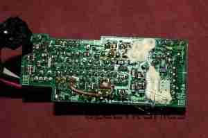
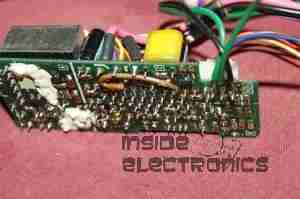
Reverse side of the PCB, very few SMT components on this board.
Tube Assembly
Tube Assembly
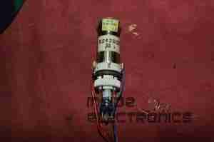
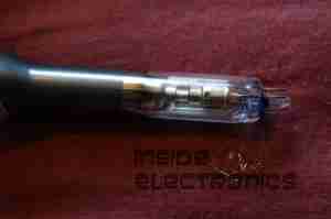
Here is an overall view of the CRT assembly with scan coils. Tube model is NEC C1M52P45.
Electron Gun
Electron Gun

Closeup view of the CRT neck, showing the electron gun assembly.


CCTV Camera
CCTV Camera

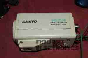
The old CCTV camera used to feed a composite signal to the CRT board. Sanyo VCC-ZM300P.

CCTV Camera Connections

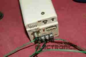
Connections at the back of the camera. Red & Black pair of wires lead to 12v power supply, Green & Black pair lead to the CRT board’s power pins. Seperate green wire is pushed into the BNC video connector for the video feed. video ground is provided by the PSU’s ground connection.

Connections
Connections

Finally the connections at the CRT drive board, left to right, +12v, Video, GND.

Screen Operation
Screen Operation

Display taking video signal from the CCTV camera.