Posted on 7 Comments

3″ CRT Composite Monitor

CRT Module

I recently managed to score a 3″ B&W portable TV on eBay, a Panasonic TR-3000G. As these old units are now useless, thanks to the switch off of analogue TV signalling, I figured I could find a composite signal internally & drive the CRT with an external source.

Panasonic TR-3000G
Panasonic TR-3000G

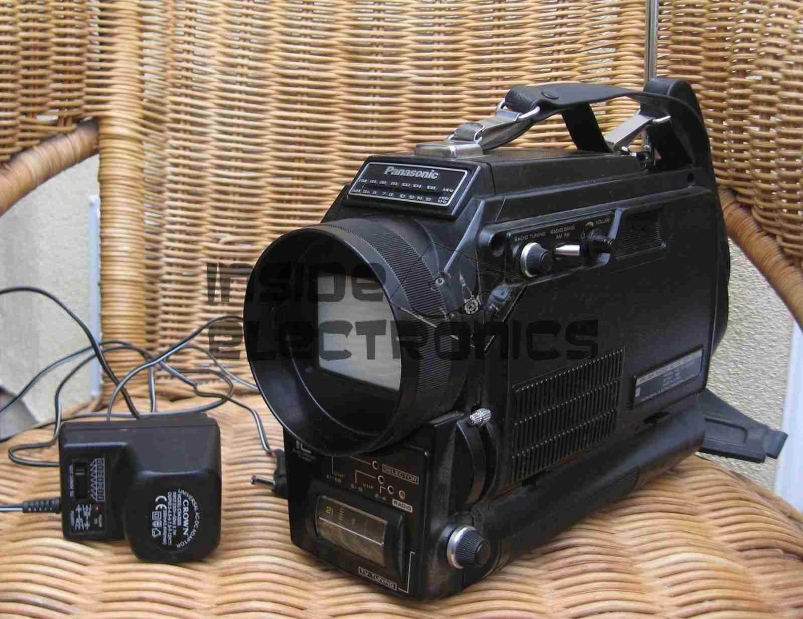
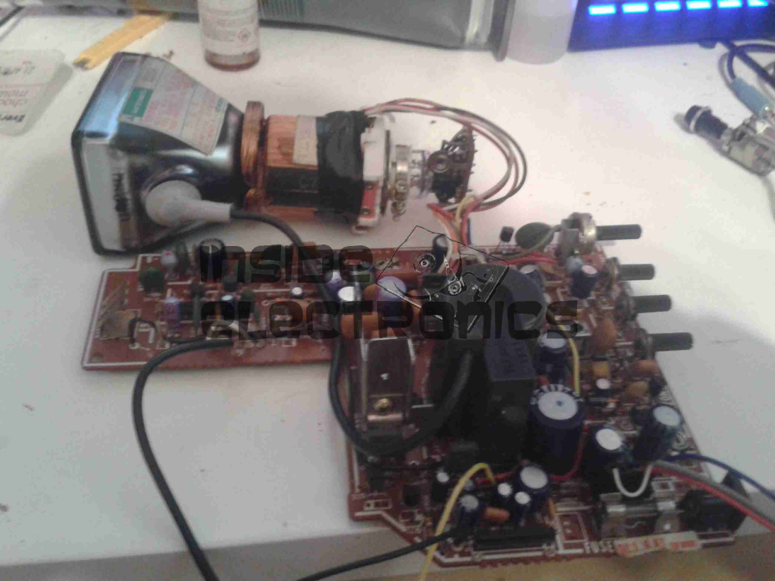
Here’s the TV in it’s native state. Running from 9v DC, or 6 D size cells. I’m guessing from somewhere around the 1970’s. Here is the CRT & associated drive circuitry, removed from the casing:

CRT Module
CRT Module

After dissecting the loom wiring between the CRT board & the RF/tuner board, I figured out I had to short out Pins 1,2 & 5 on the H header to get the CRT to operate straight from the power switch. This board also generates the required voltages & signals to drive the RF tuner section. I have removed the loom from this, as the PCB operates fine without. It doesn’t seem to be fussy about power input either: it’s specified at 9v, but seems to operate fine between 7.5v & 14.5v DC without issue.

Video Connections
Video Connections

Tracing the wiring from the tuner PCB revealed a length of coax snaking off to the section marked Video/Sync. I successfully found the composite input!

Running OSMC
Running OSMC

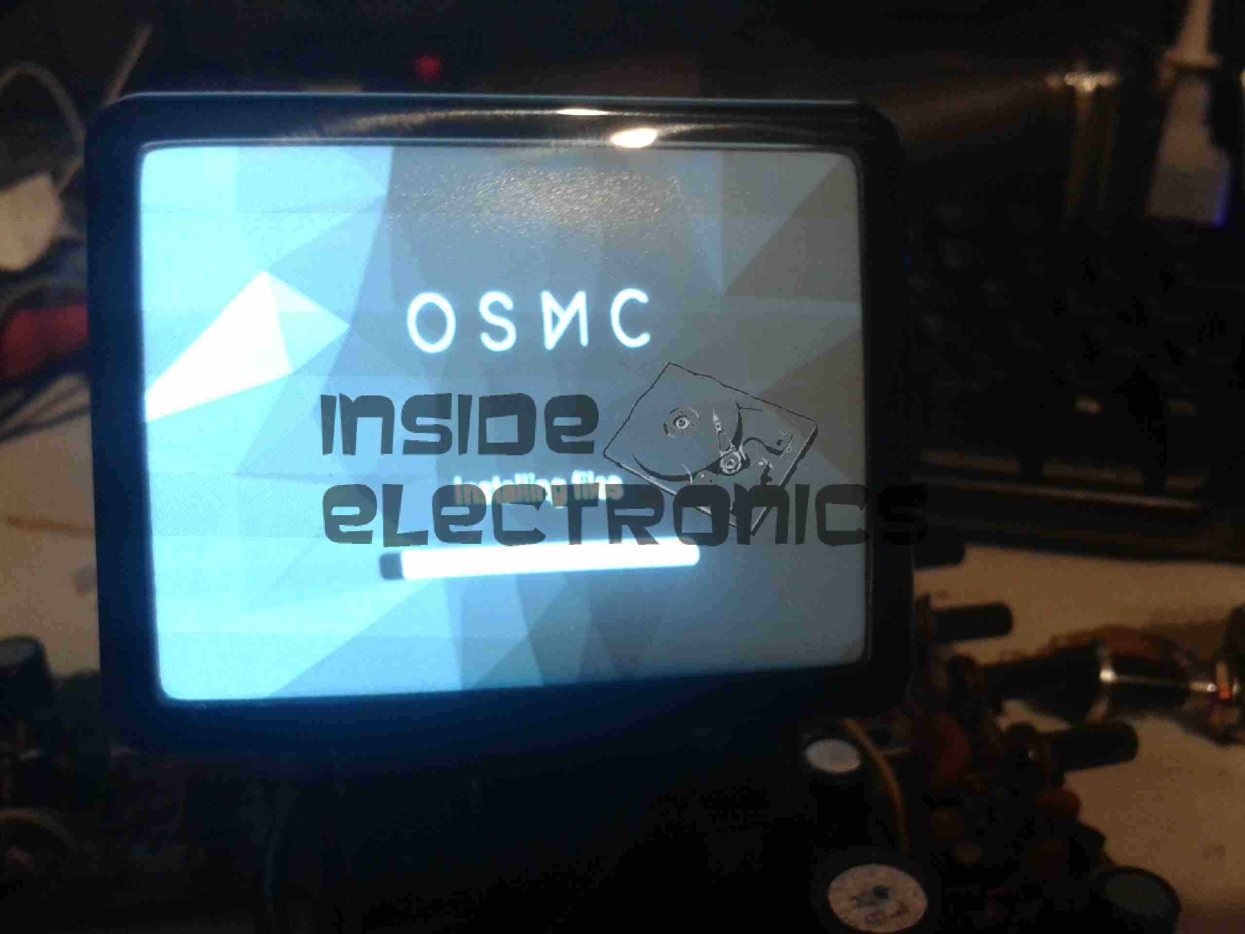
A quick bit of wiring to a Raspberry Pi, & we have stable video! For such an old unit, the picture quality is brilliant, very sharp focus.

Matsushita 85VB4 CRT

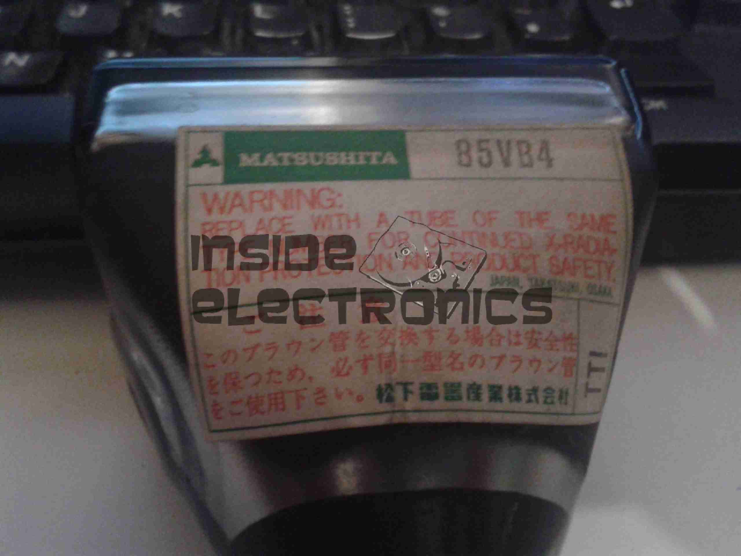
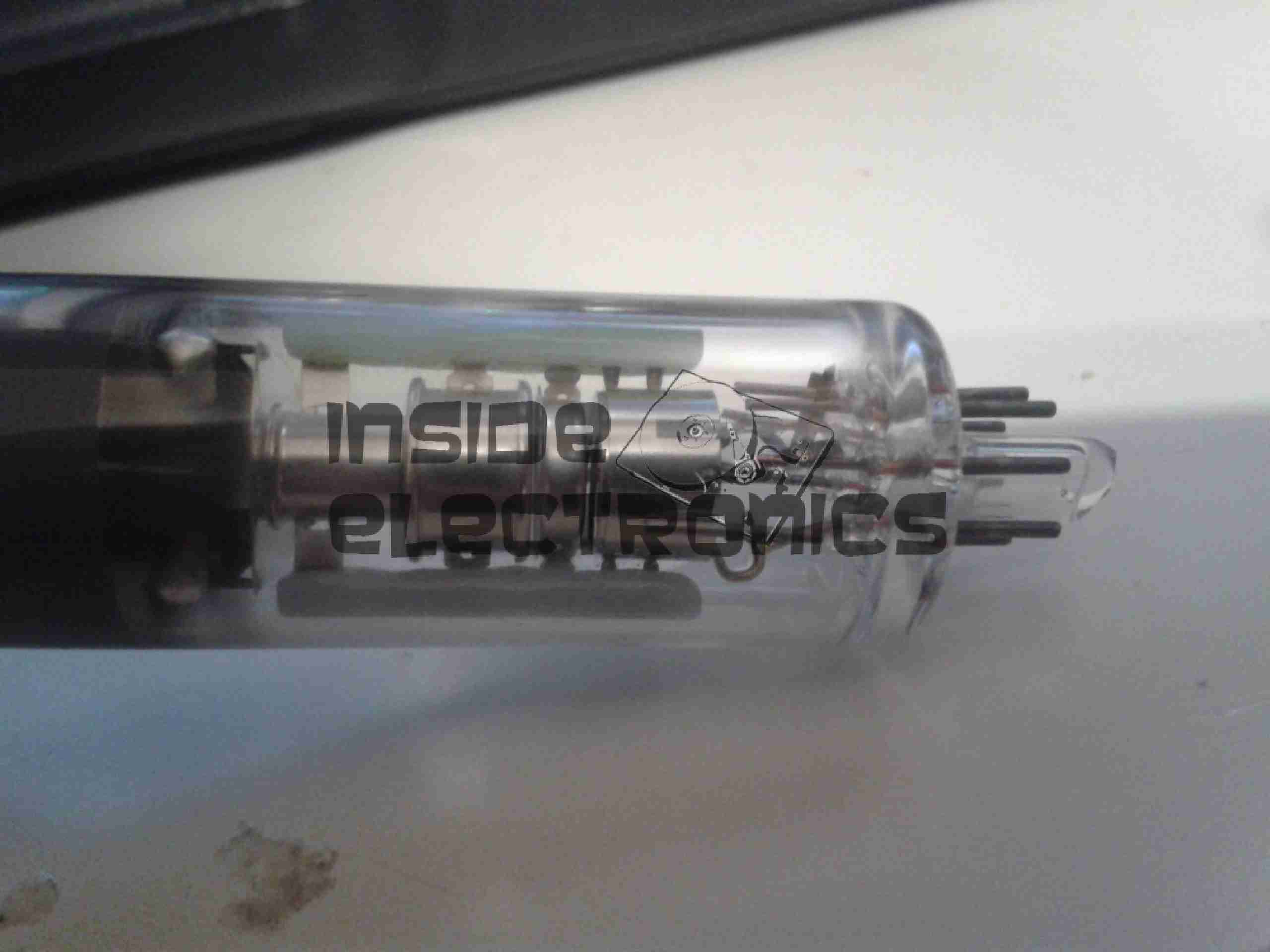
Closeup of the CRT itself. I haven’t been able to find much data on this unit, but I’m guessing it’s similar to many commercial viewfinder CRTs.

Electron Gun Closeup

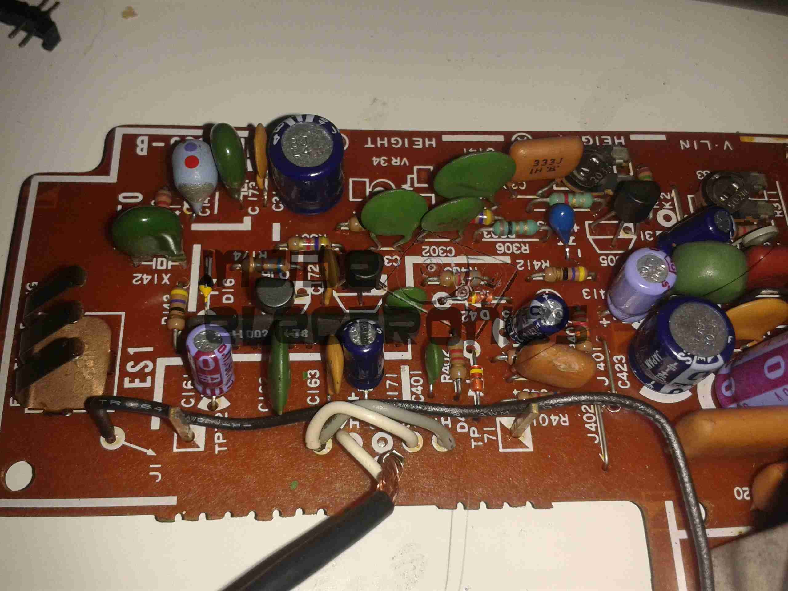
Amazingly, there isn’t a single IC in the video circuitry, it’s all discrete components. This probably accounts for the large overall size of the control PCB. Viewfinder CRTs from a few years later on are usually driven with a single IC & a few passives that provide all the same functions.  

Posted on 3 Comments

Wearable Raspberry Pi Part 1

Overview
Overview

Here is the project I’m currently working on. A completely wearable computing platform based on the Raspberry Pi & the WiFi Pineapple.

Above can be seen the general overview of the current unit.

On the left:

  • Alfa AWUS036NHA USB High Power WiFi Network Interface
  • 512MB Model B Raspberry Pi, 16GB SD card, running Raspbian & LXDE Desktop. Overclocked to 1GHz.

On the right:

  • WiFi Pineapple router board
  • USB 3G card.

The WiFi, Pineapple & 3G all have external antenna connections for a better signal & the whole unit locks onto the belt with a pair of clips.
The Raspberry Pi is using the composite video output to the 7″ LCD I am using, running at a resolution of 640×480. This gives a decent amount of desktop space while retaining readability of the display.

The case itself is a Pelican 1050 hard case, with it’s rubber lining removed. The belt clips are also a custom addition.

Connections
Connections

Here are the connections to the main unit, on the left is the main power connector, supplying +5v & +12v DC. The plug on the right is an 8-pin connection that carries two channels of video, mono audio & +12v power to the display.
Currently the only antenna fitted is the 3G.

Connectors
Connectors

Closeup of the connections for power, audio & video. The toggle switch is redundant & will soon be replaced with a 3.5mm stereo jack for headphones, as an alternative to the mono audio built into the display.

Test Run
Test Run

Current state of test. Here the unit is running, provided with an internet connection through the Pineapple’s 3G radio, funneled into the Pi via it’s ethernet connection.

Pi Goodness!
Pi Goodness!

Running on a car reversing camera monitor at 640×480 resolution. This works fairly well for the size of the monitor & the text is still large enough to be readable.


Stay tuned for Part 2 where I will build the power supply unit.


Posted on 10 Comments

Camcorder CRT Viewfinder

CRT Assembly
CRT Assembly

Here are the viewfinder electronics from a 1984 Hitachi VHS Movie VM-1200E Camcorder. These small CRT based displays accept composite video as input, plus 5-12v DC for power.

Screen
Screen

Here is the front face of the CRT, diameter is 0.5″.

Power Board
Power Board

Closeup view of the PCB, there are several adjustments & a pair of connectors. Socket in the upper left corner is the power/video input. Pinout is as follows:

  1. Brown – GND
  2. Red – Video Input
  3. Orange – +12v DC
  4. Yellow – Record LED
The potentiometers on the PCB from left:
  1. H. ADJ
  2. V. ADJ
  3. BRIGHT
  4. FOCUS
PCB Part Number reads: EM6-PCB
This unit utilises the BA7125L deflection IC.
Solderside
Solderside
Reverse side of the PCB, very few SMT components on this board.
Tube Assembly
Tube Assembly
Here is an overall view of the CRT assembly with scan coils. Tube model is NEC C1M52P45.
Electron Gun
Electron Gun

Closeup view of the CRT neck, showing the electron gun assembly.


CCTV Camera
CCTV Camera

The old CCTV camera used to feed a composite signal to the CRT board. Sanyo VCC-ZM300P.

CCTV Camera Connections

Connections at the back of the camera. Red & Black pair of wires lead to 12v power supply, Green & Black pair lead to the CRT board’s power pins. Seperate green wire is pushed into the BNC video connector for the video feed. video ground is provided by the PSU’s ground connection.

Connections
Connections

Finally the connections at the CRT drive board, left to right, +12v, Video, GND.

Screen Operation
Screen Operation

Display taking video signal from the CCTV camera.

Posted on Leave a comment

Grand Hand View

Front
Front

This is an adaptor to convert computer VGA to composite & S-Video output for a normal TV.

Bottom
Bottom

Bottom of the unit with option select switch.

PCB Top
PCB Top

PCB removed from the casing, CPU in centre, buffer RAM on the right.

PCB Bottom
PCB Bottom

Reverse side with the VGA connections at the top & the S-Video/composite outputs on the bottom.

VGA
VGA

Inputs. USB connector provides power, pair of VGA connectors provides passthrough function.

S-Video & Composite
S-Video & Composite

Outputs. Standard S-Video on the left & composite video on the right.

Posted on Leave a comment

Xbox 360 HD A/V Cable

Connectors
Connectors

Teardown of the Xbox 360 HD A/V cable. Standard Xbox connector on the left. Component video/audio/composite video connectors on the right.

Internals
Internals

Internals of the Xbox connector. Black unit is fiber optic audio connector, PCB underneath holds the HD/SD video switch.