Posted on 2 Comments

Sony HVF-2000P Viewfinder Teardown & Composite Video Hack

Rating Plate
Rating Plate

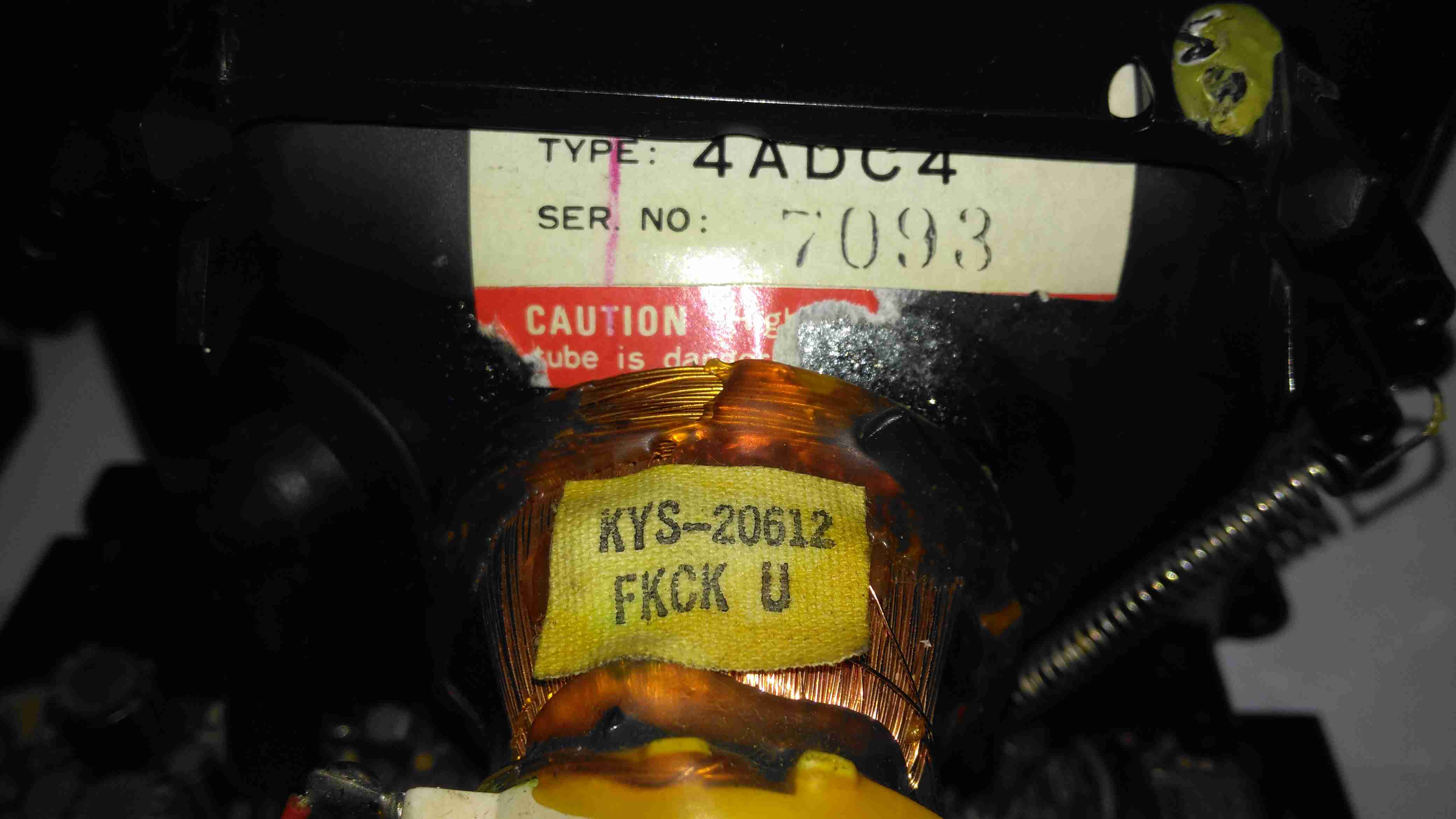
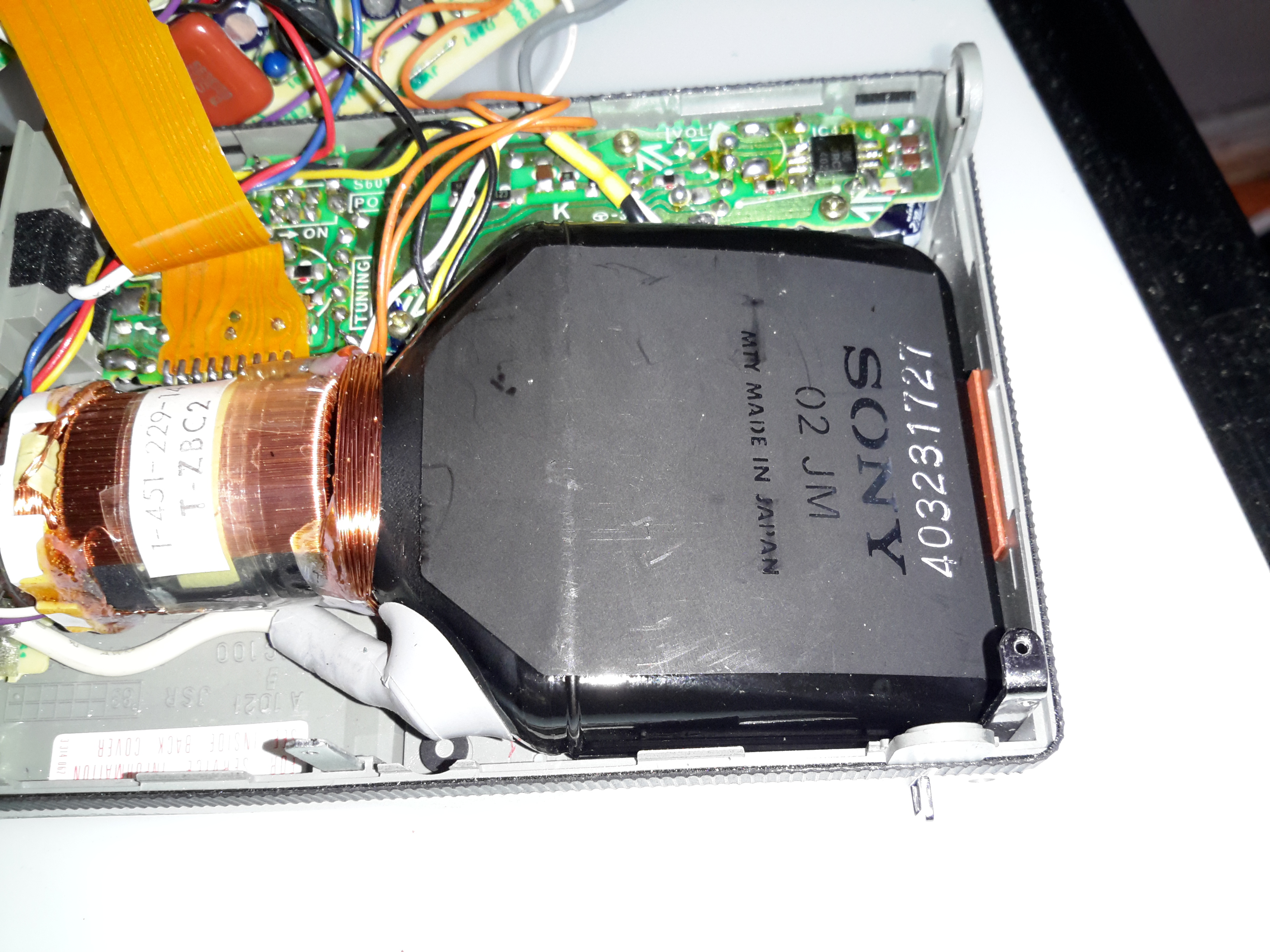
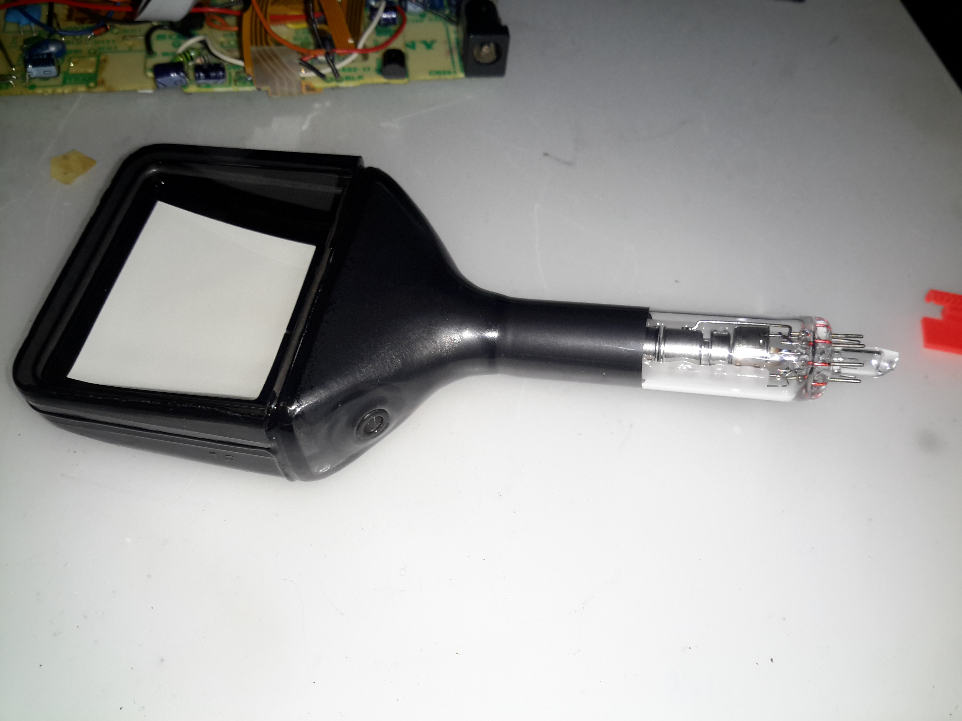
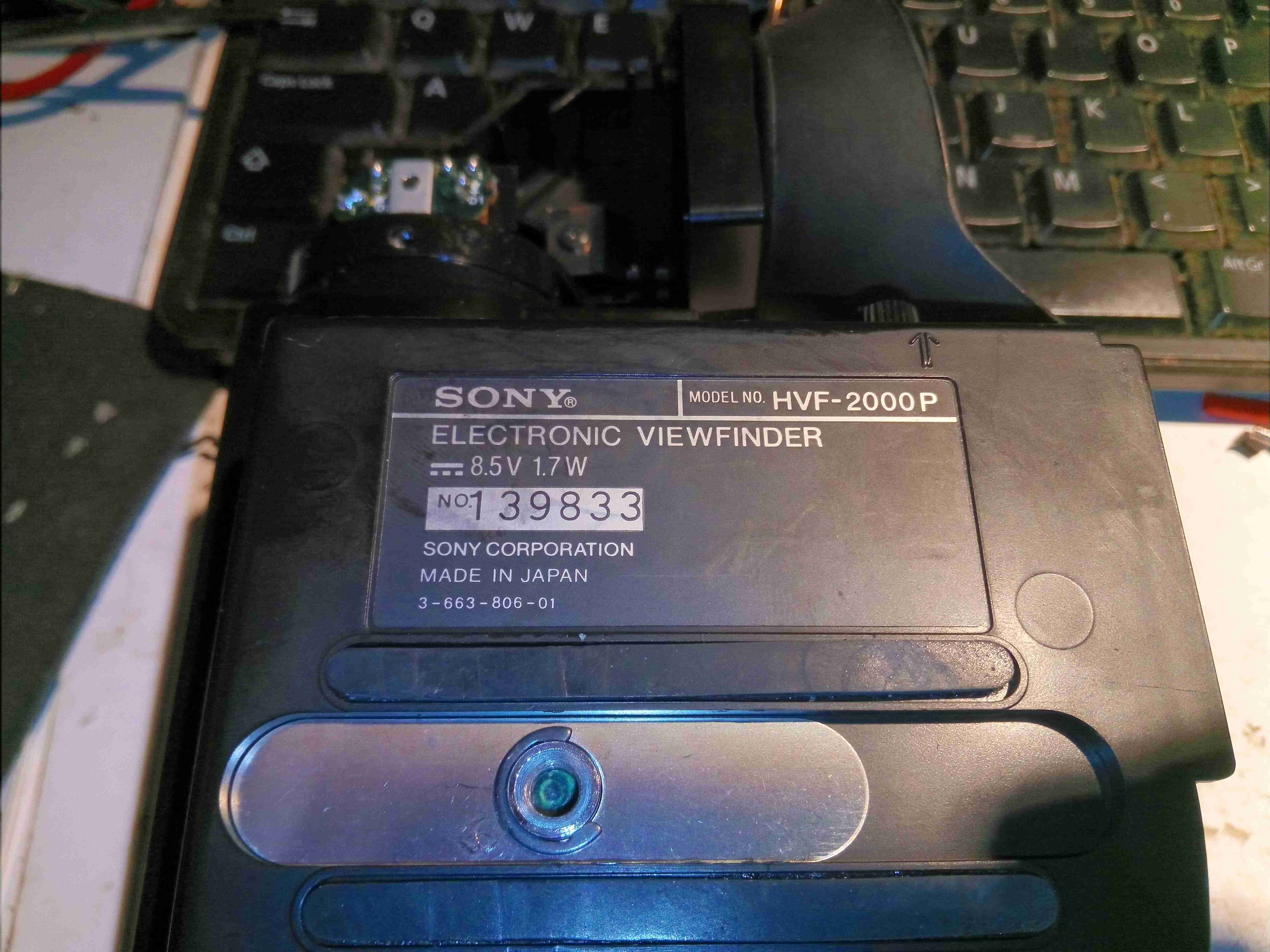
Well, it’s time for another viewfinder hack! I’ve been after one of these for a while, this is from an early 1980’s era Sony Trinicon camera, and instead of the tiny ½” round CRT display, these have a 1.5″ square CRT – a Matsushita 40CB4. Luckily I managed to score a pair of these from eBay for very little money. Update: The second camera’s viewfinder module turned out to have a dead flyback transformer, but at least I have a good spare CRT & the rest of the support components. More to come later on the teardown of the camera itself.

Mirror & Eyecup Assembly

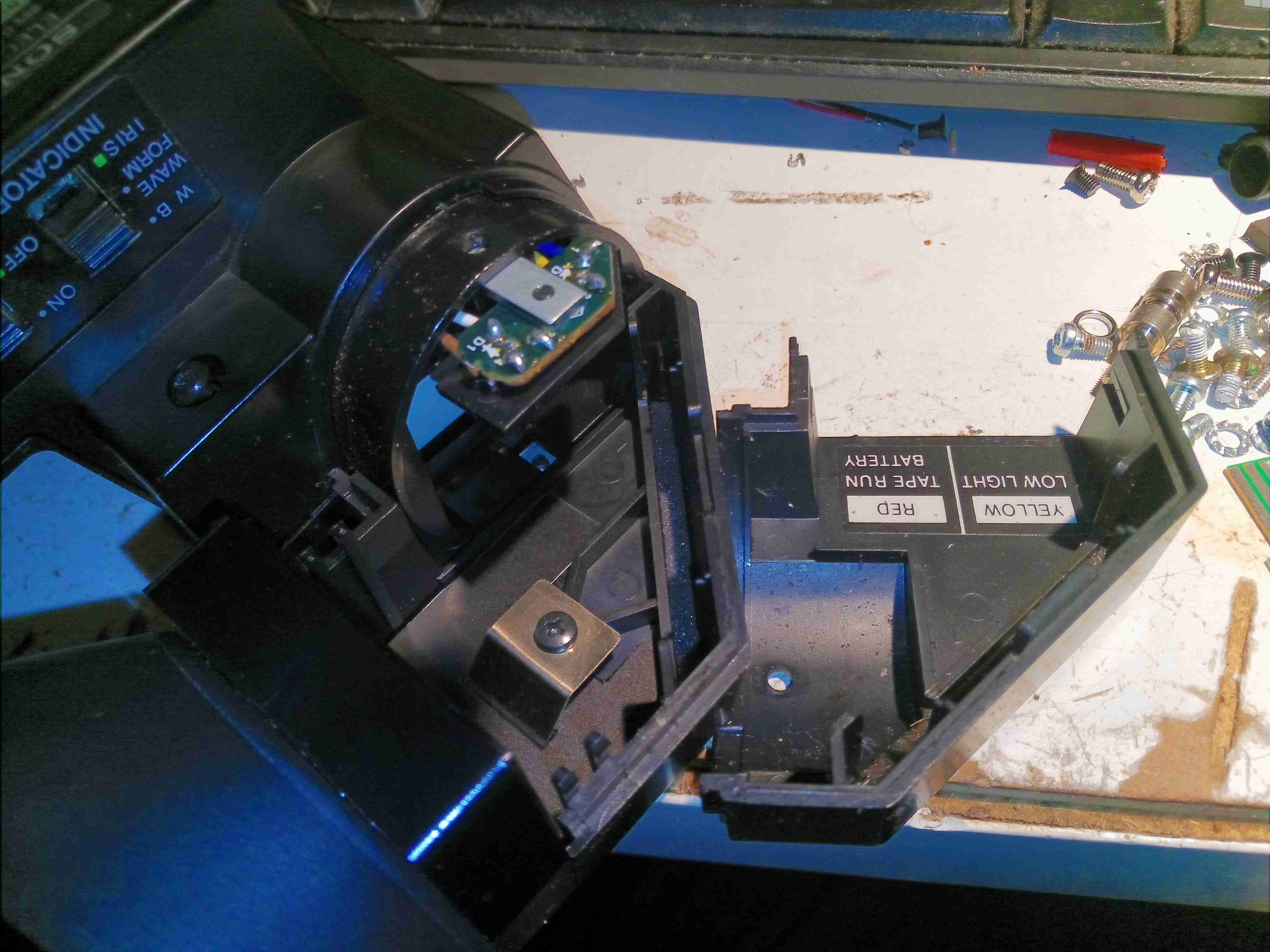
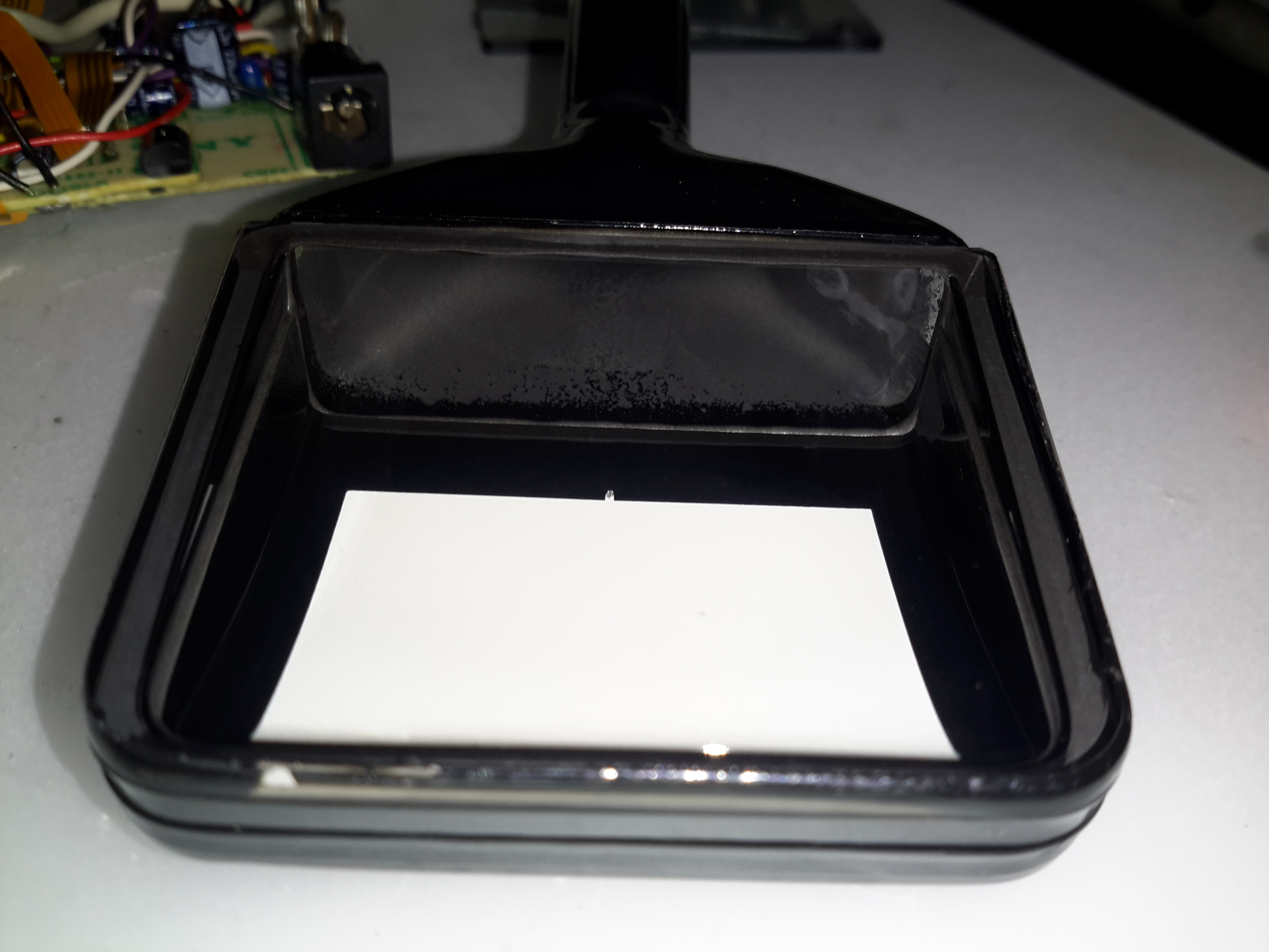
The eyecup assembly with the magnifying lens & turning mirror is easy to remove, with clips & a single screw holding it onto the CRT holder sticking out of the side of the main casing.

Top Cover Removed
Top Cover Removed

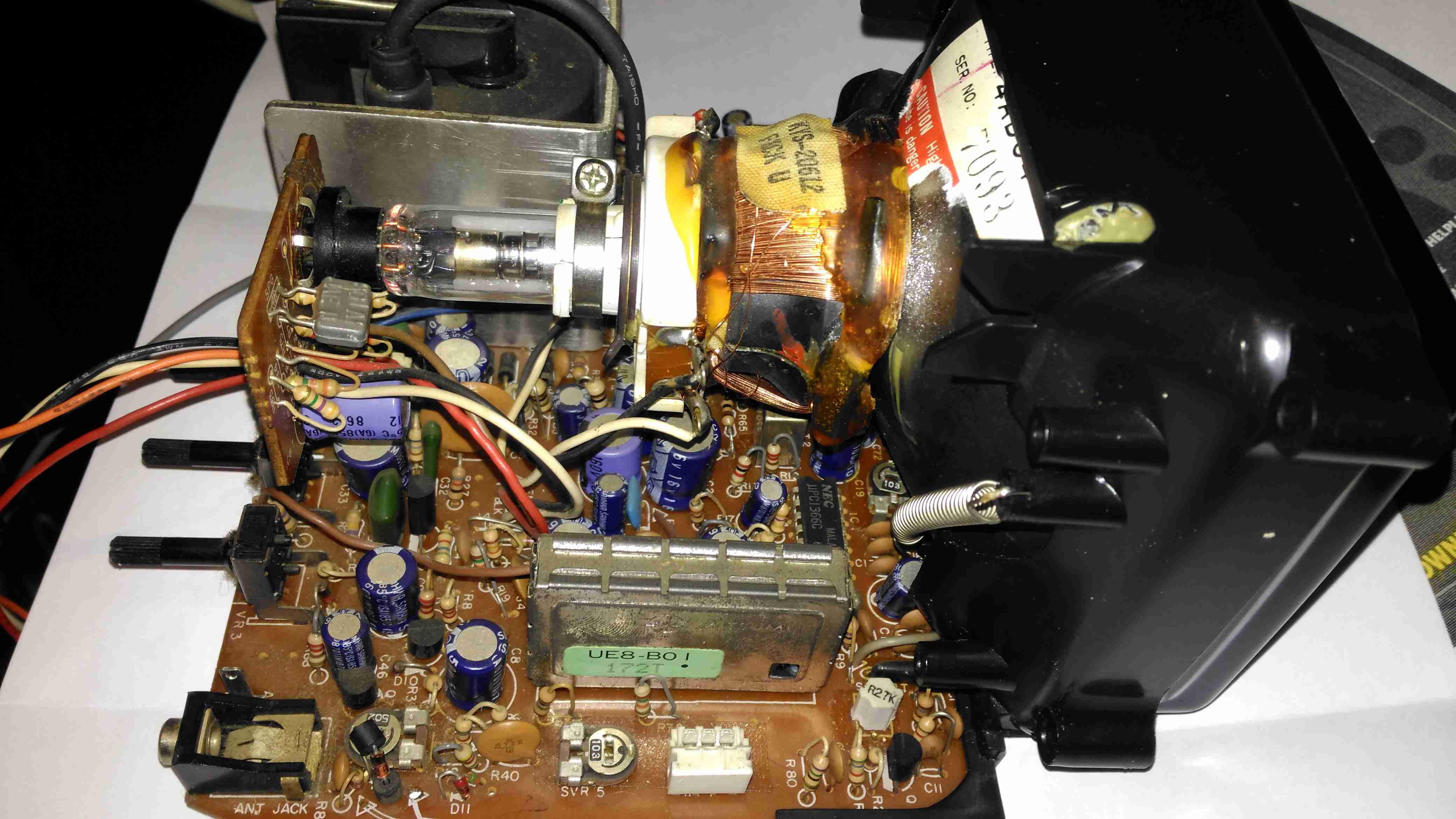
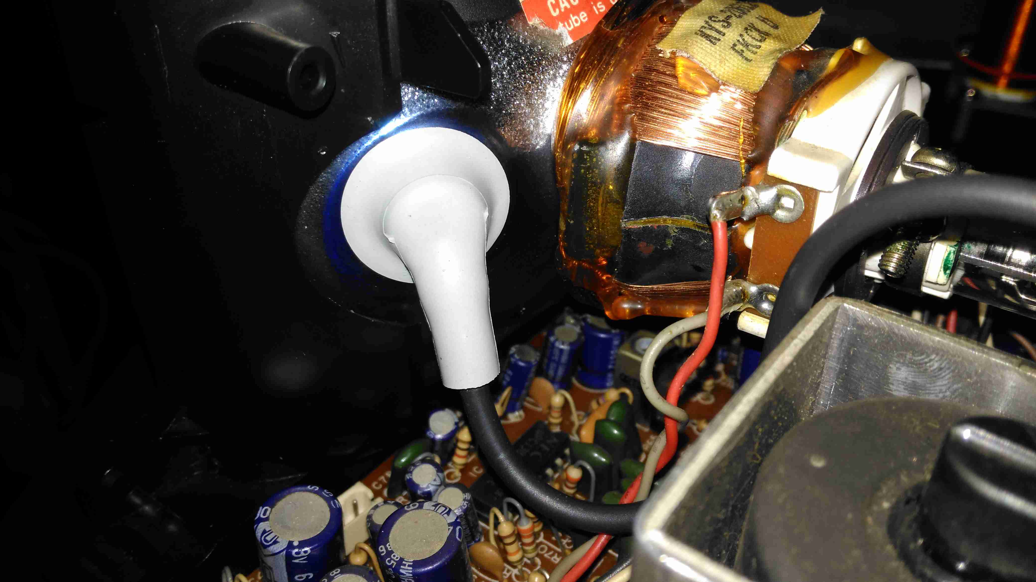
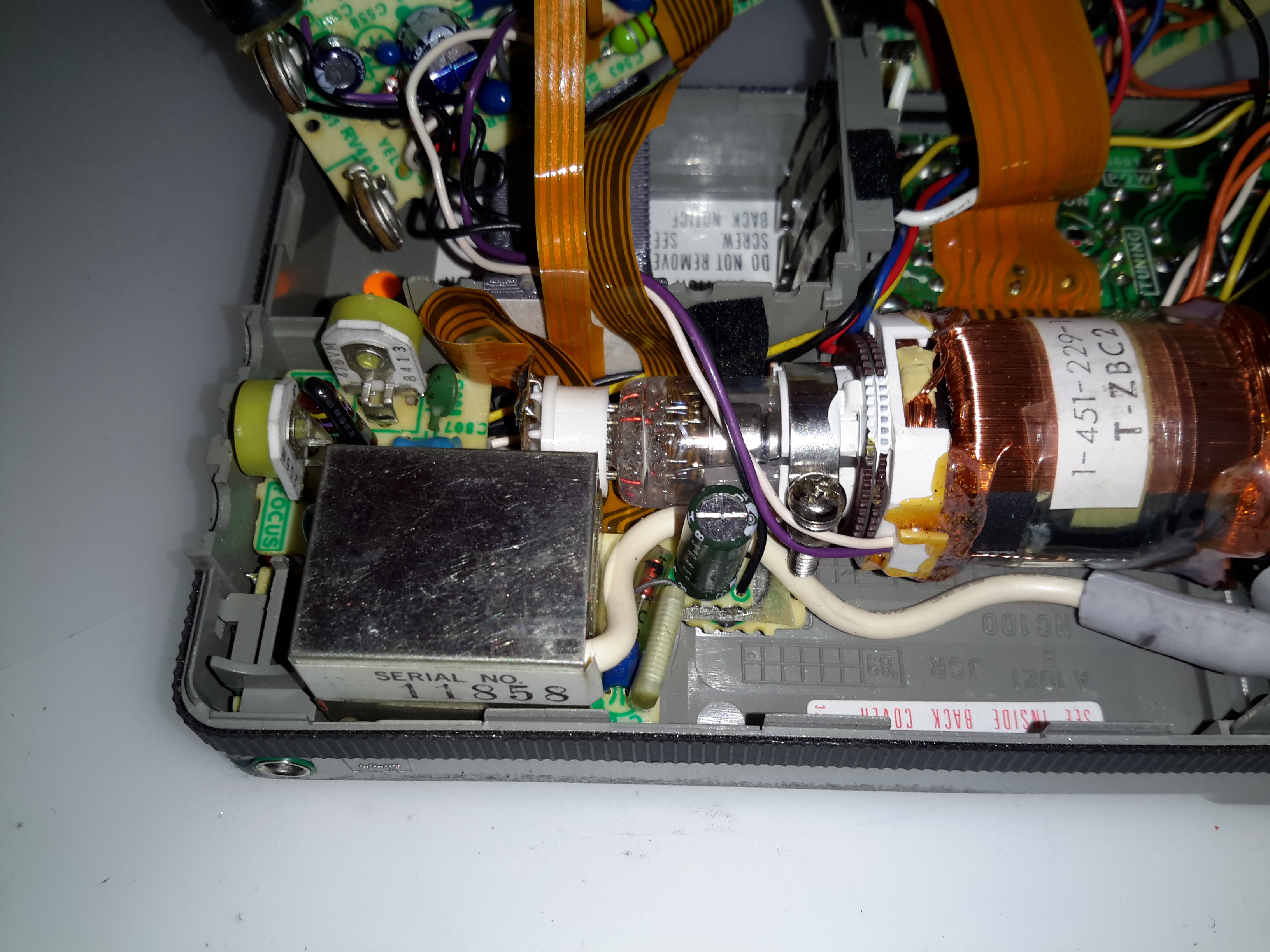
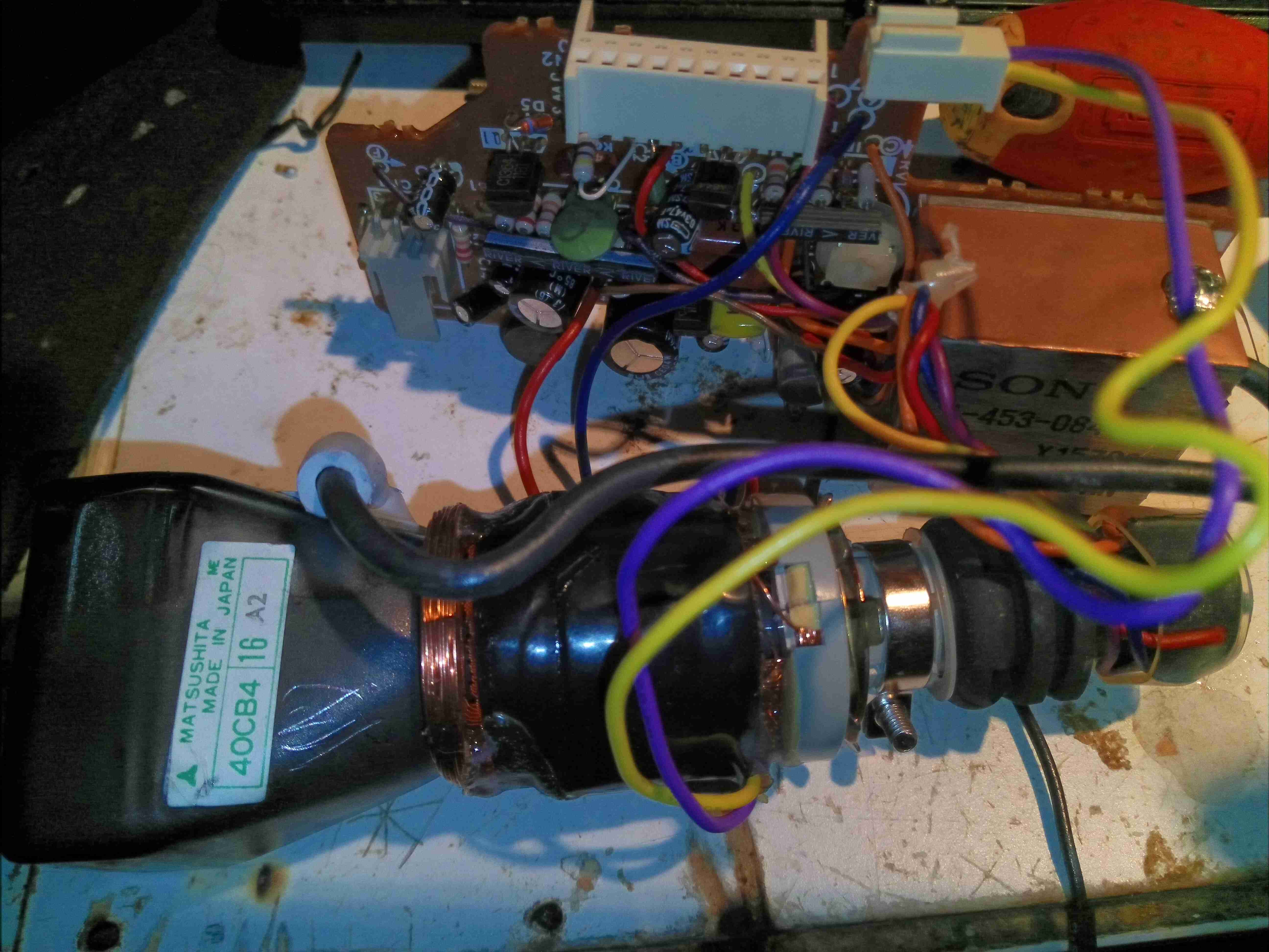
Removing some screws around the case allows the top cover to be removed, revealing the electronics. There’s certainly more in here than the later camera viewfinders, in this unit there are two boards slotted together with a board-to-board interconnect at the bottom. The CRT is at the top of the photo, hiding inside the plastic housing & deflection yoke assembly.

Bare PCBs & CRT
Bare PCBs & CRT

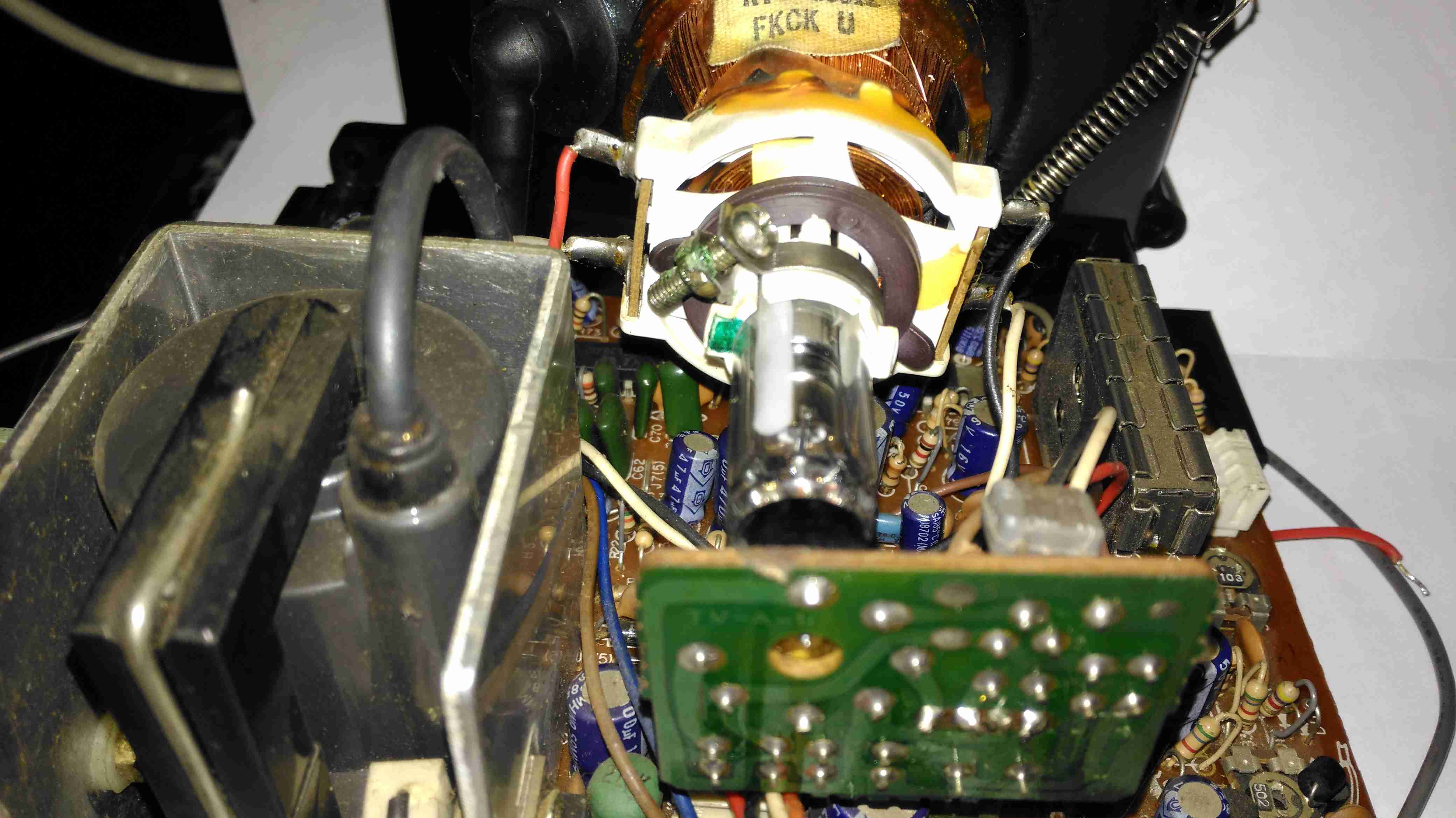
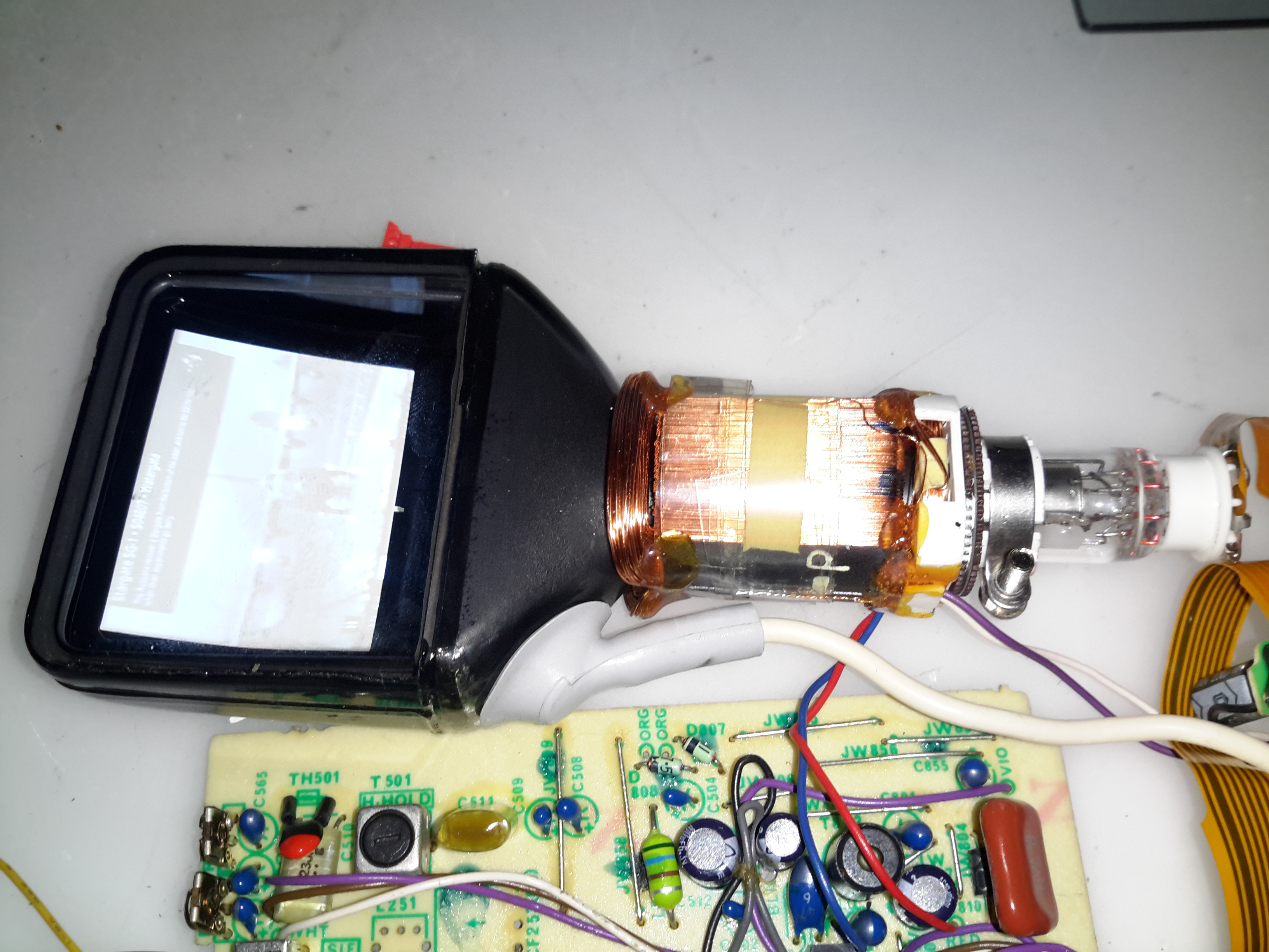
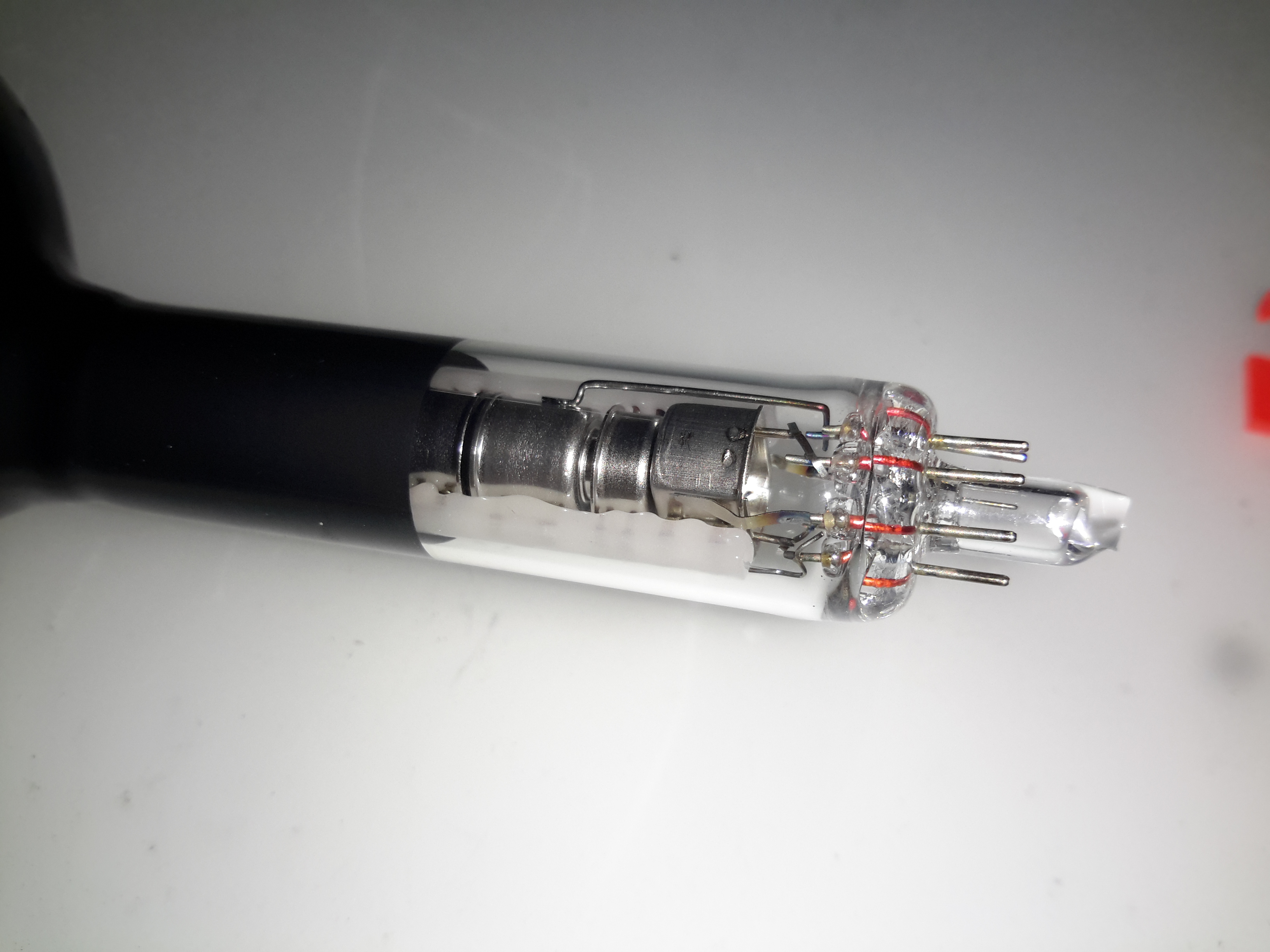
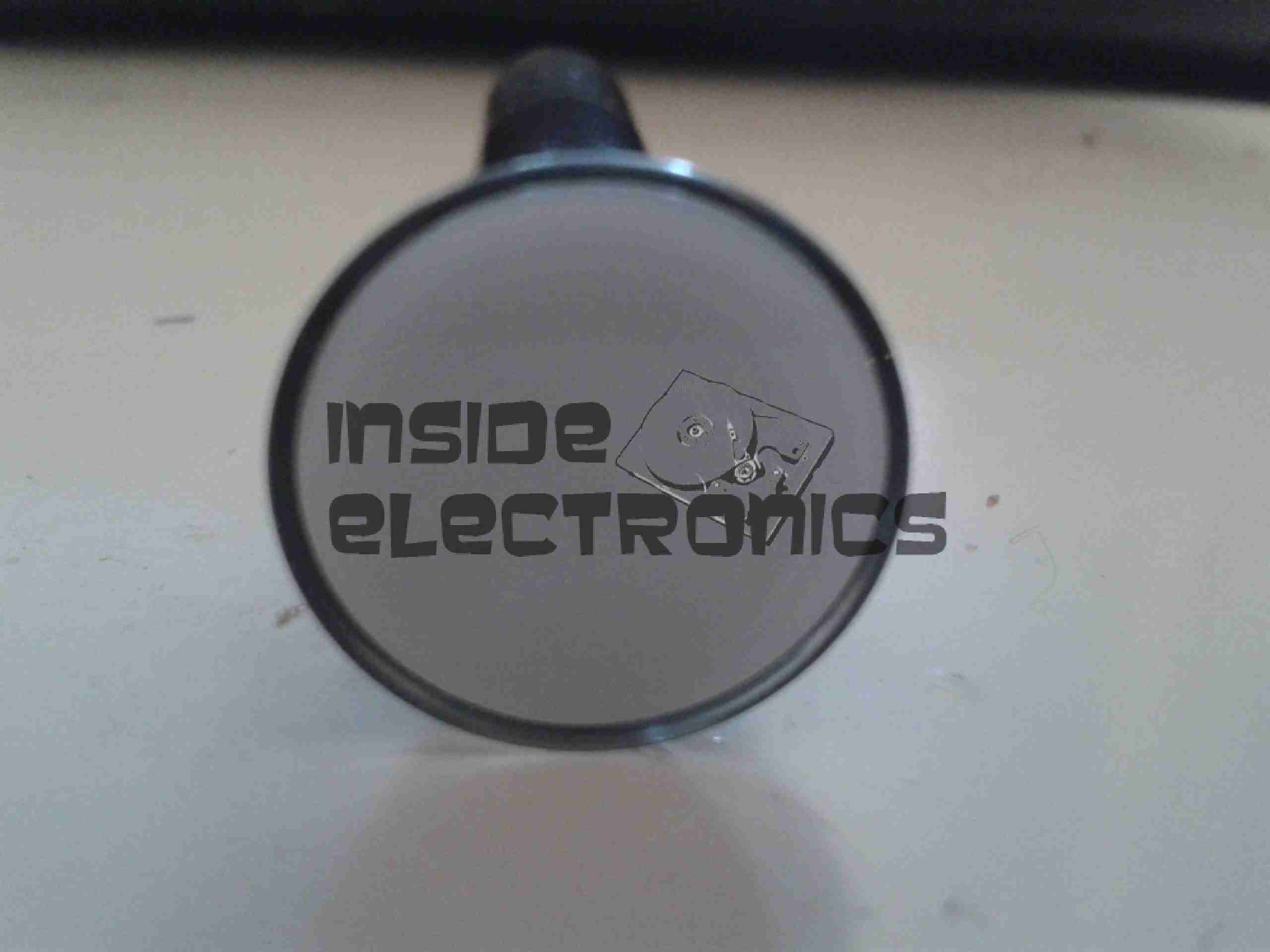
Here’s the CRT & one of the control boards removed from the case, having been stripped of the heatshrink tube that held the final anode lead in place. Just like on larger CRTs, this viewfinder has the final anode on a cavity connector fused into the bell, instead of being led out to a pin on the base. This is probably due to the much higher anode voltage of 5kV, a big jump from the 2kV on the ½” round tubes.

40CB4 CRT Label
40CB4 CRT Label

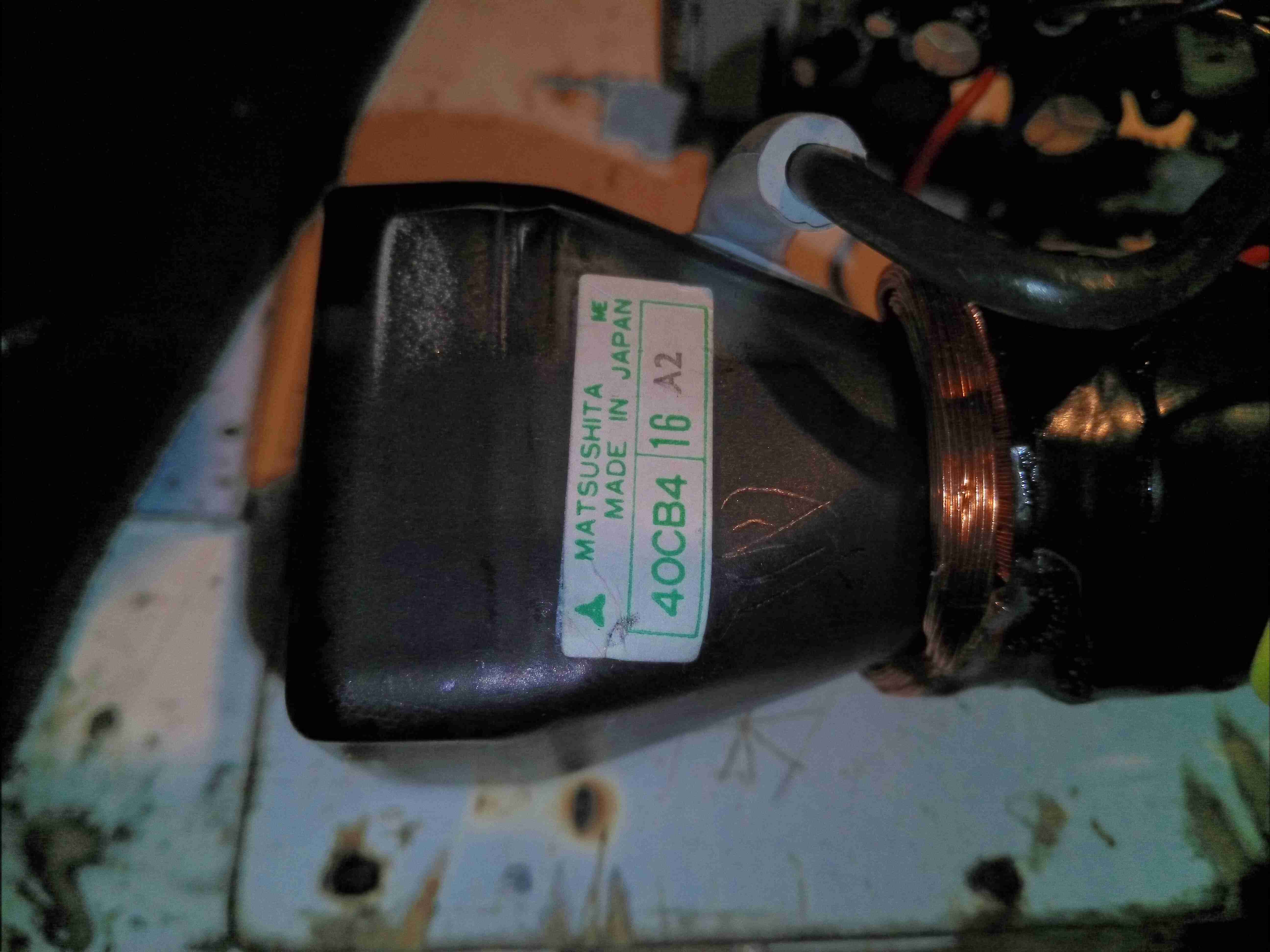
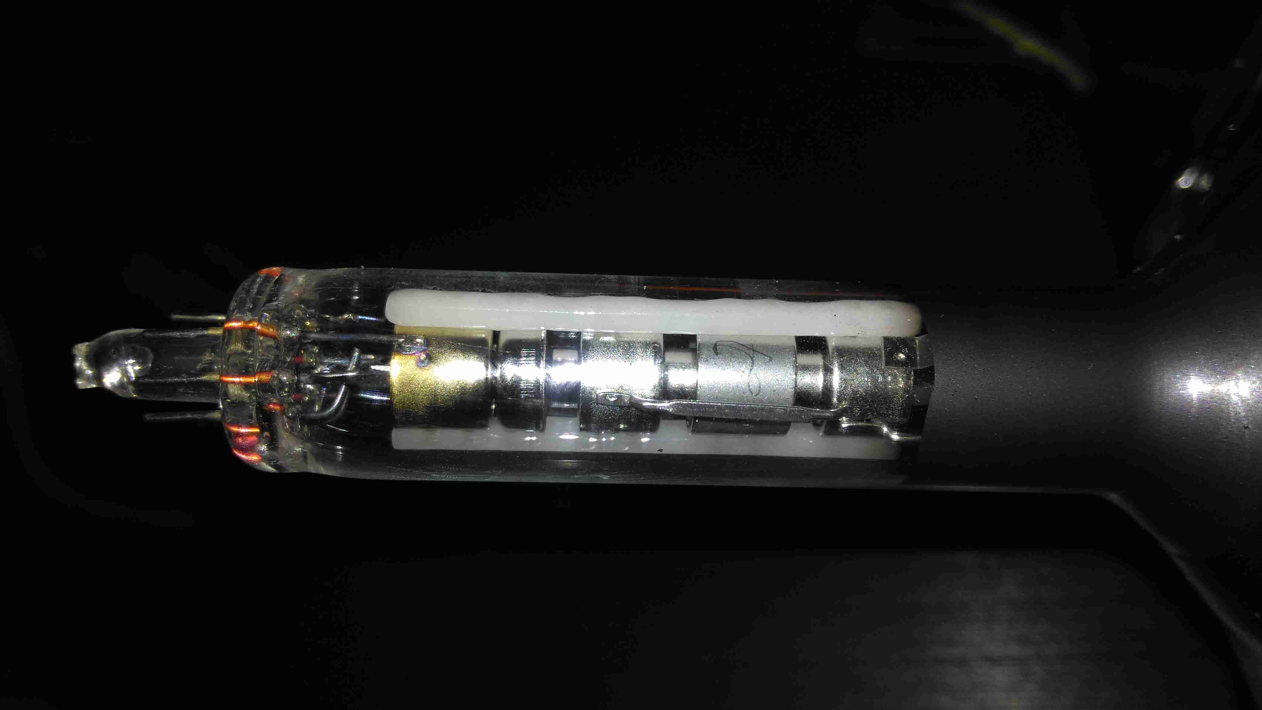
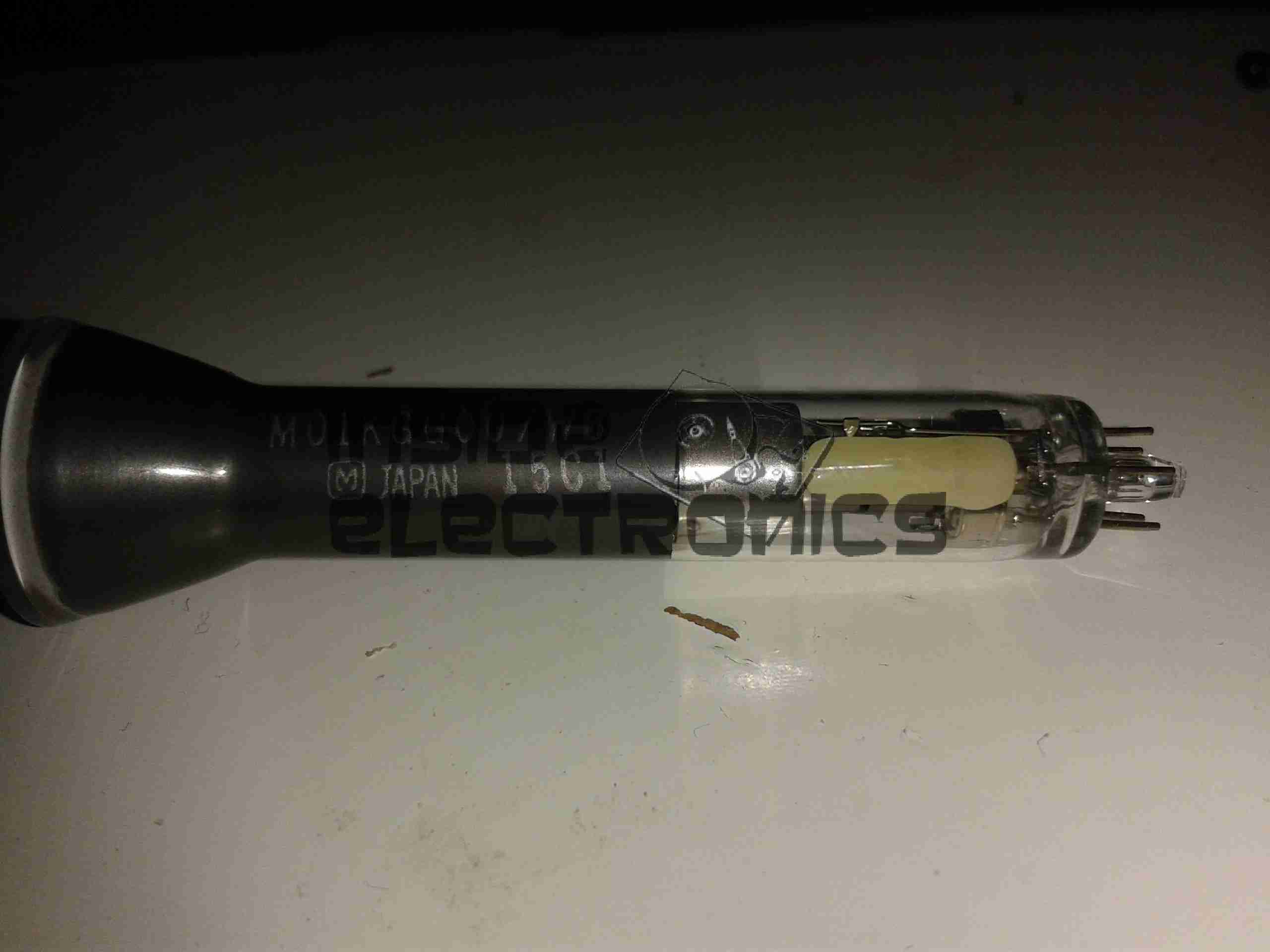
Yup, it’s definitely the elusive 40CB4. Apparently these CRTs are still manufactured to this day for professional camera viewfinders, as the resolution of this small vacuum tube is still better than similarly sized modern tech such as LCDs or OLEDs. The phosphor used is type P4 – ZnS:Ag+(Zn,Cd)S:Ag, with an aluminized overcoat.

Bare 40CB4 CRT
Bare 40CB4 CRT

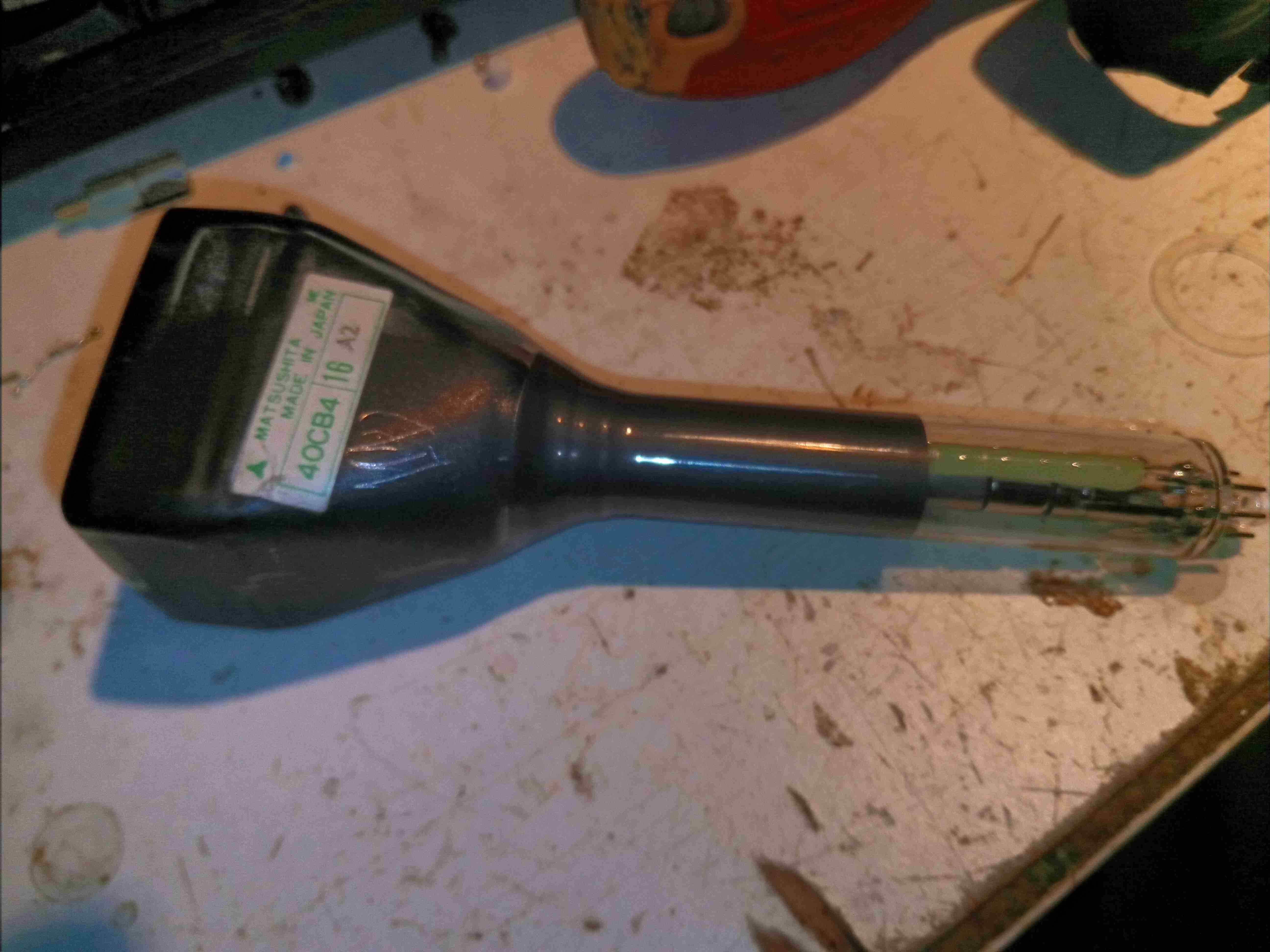
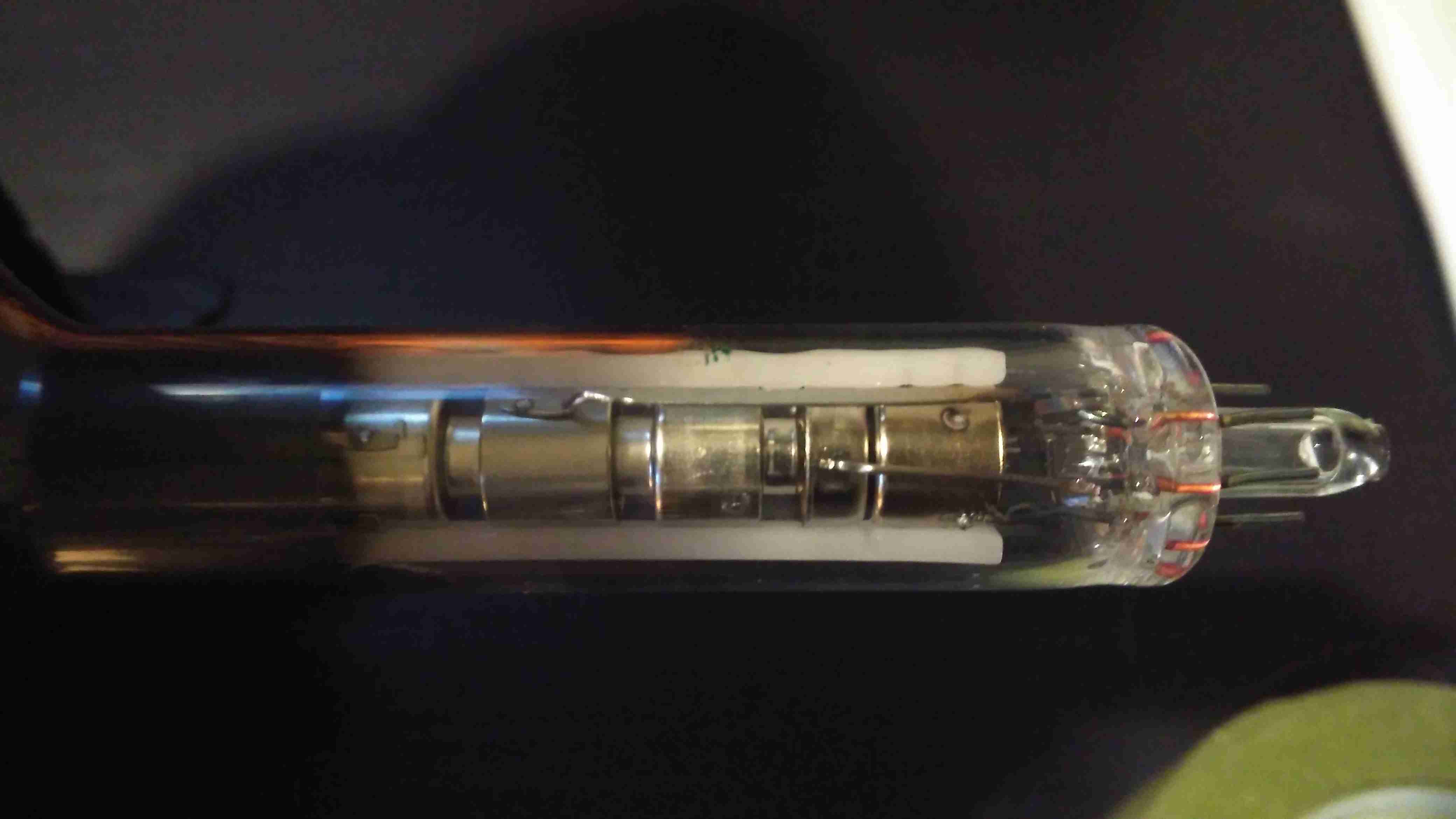
After the base connector & deflection yoke are removed from the tube, the very long neck can be seen, this long glass neck apparently giving better focus & resolution than the stubbier tubes.

Electron Gun
Electron Gun

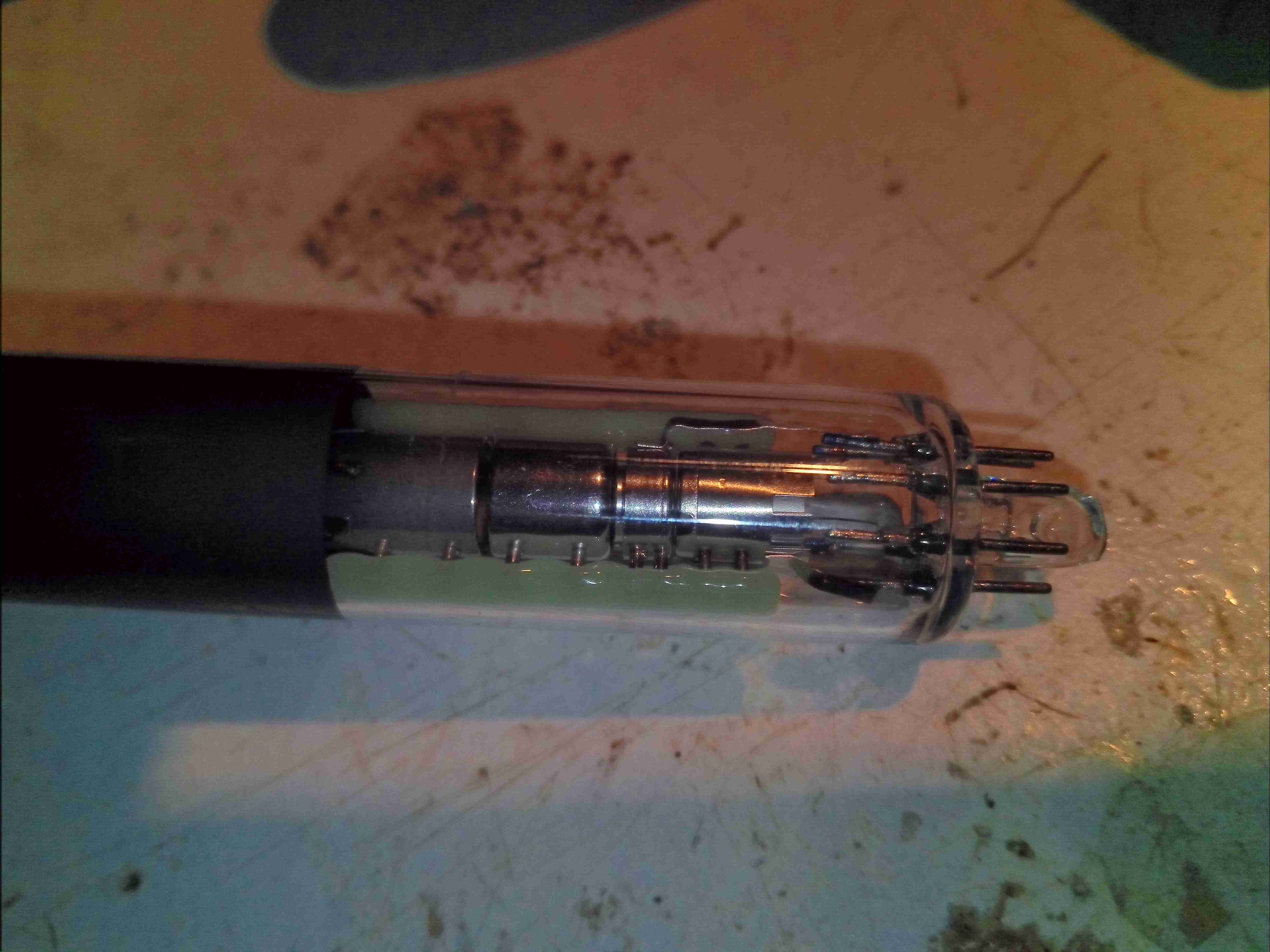
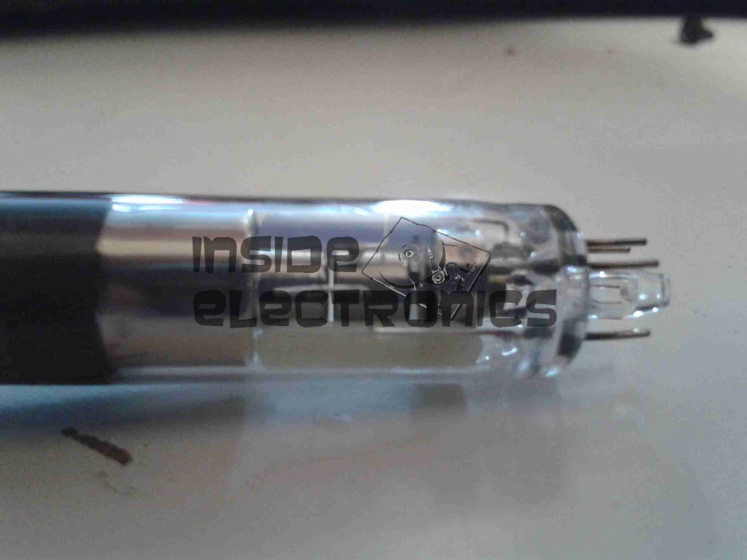
The electron gun is the usual single unit as usually found in monochrome tubes.

Deflection Board
Deflection Board

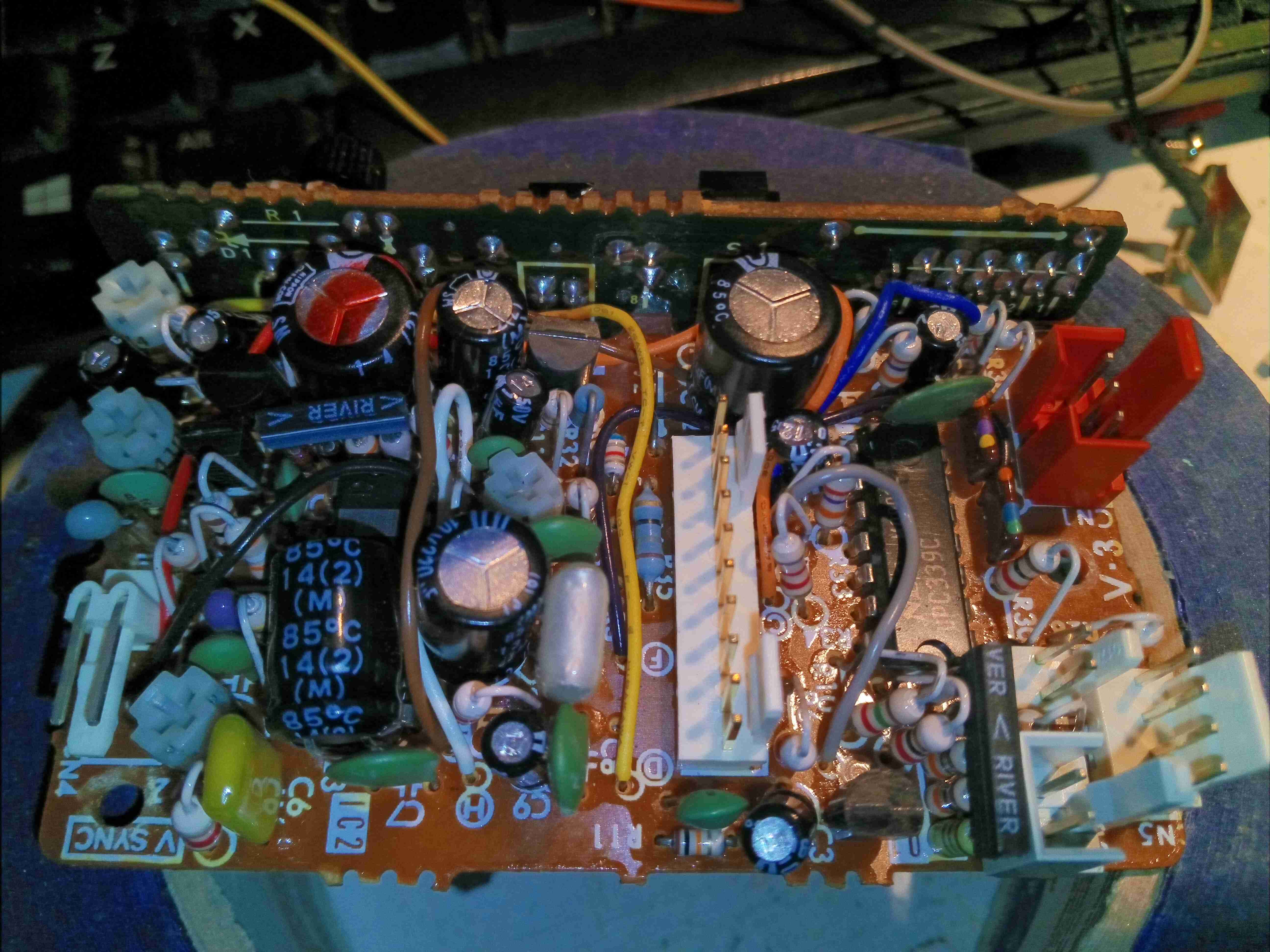
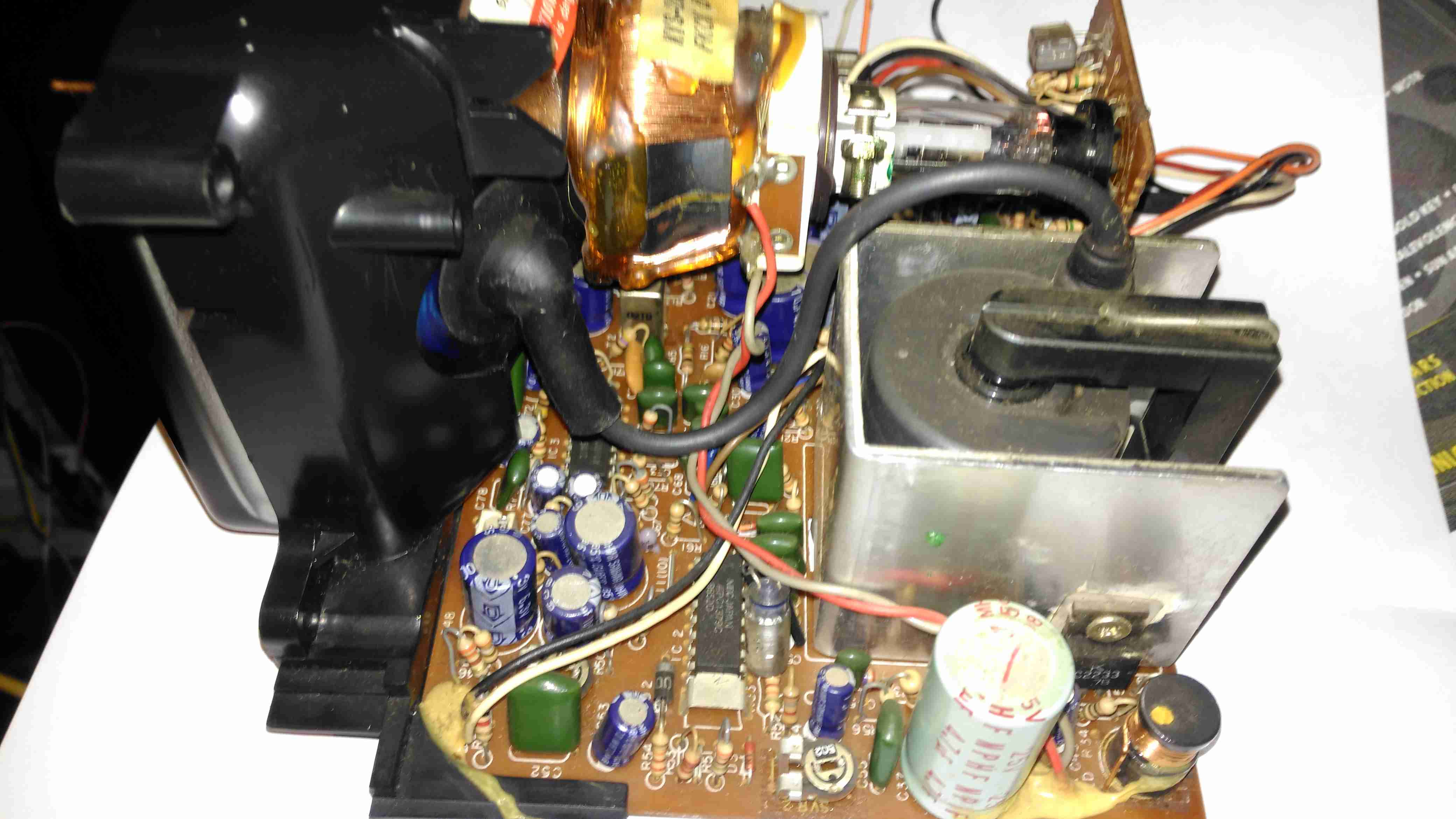
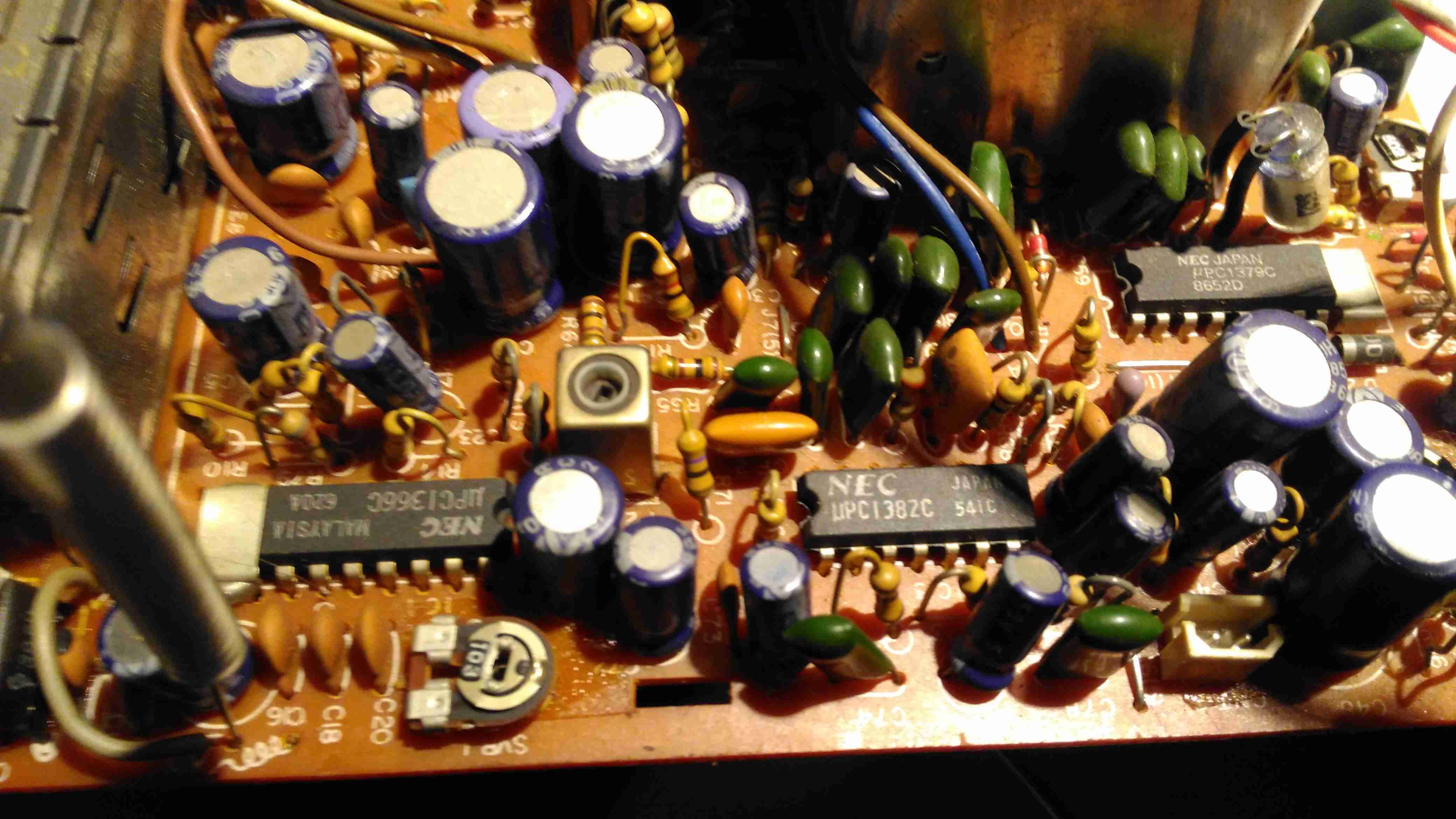
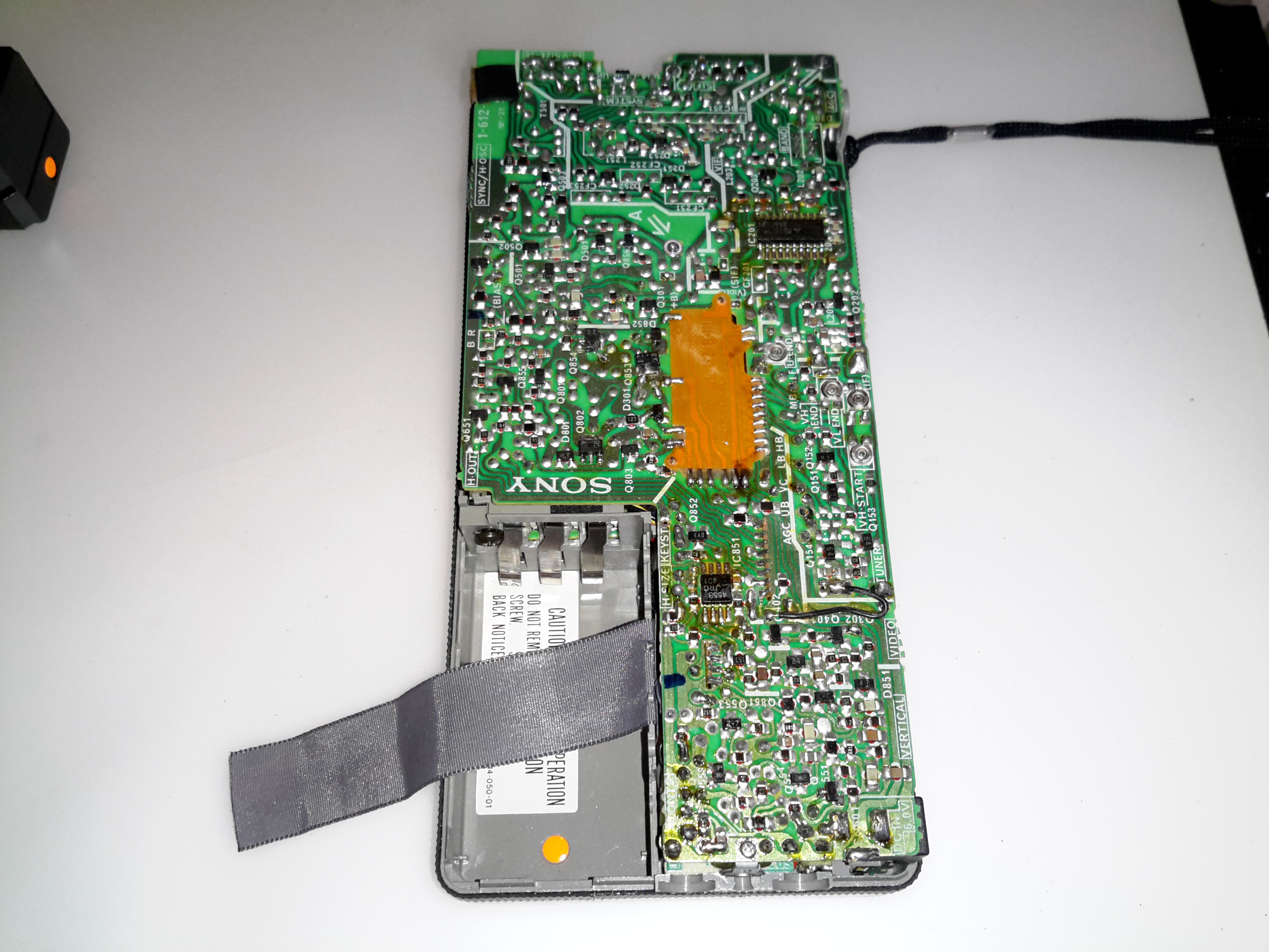
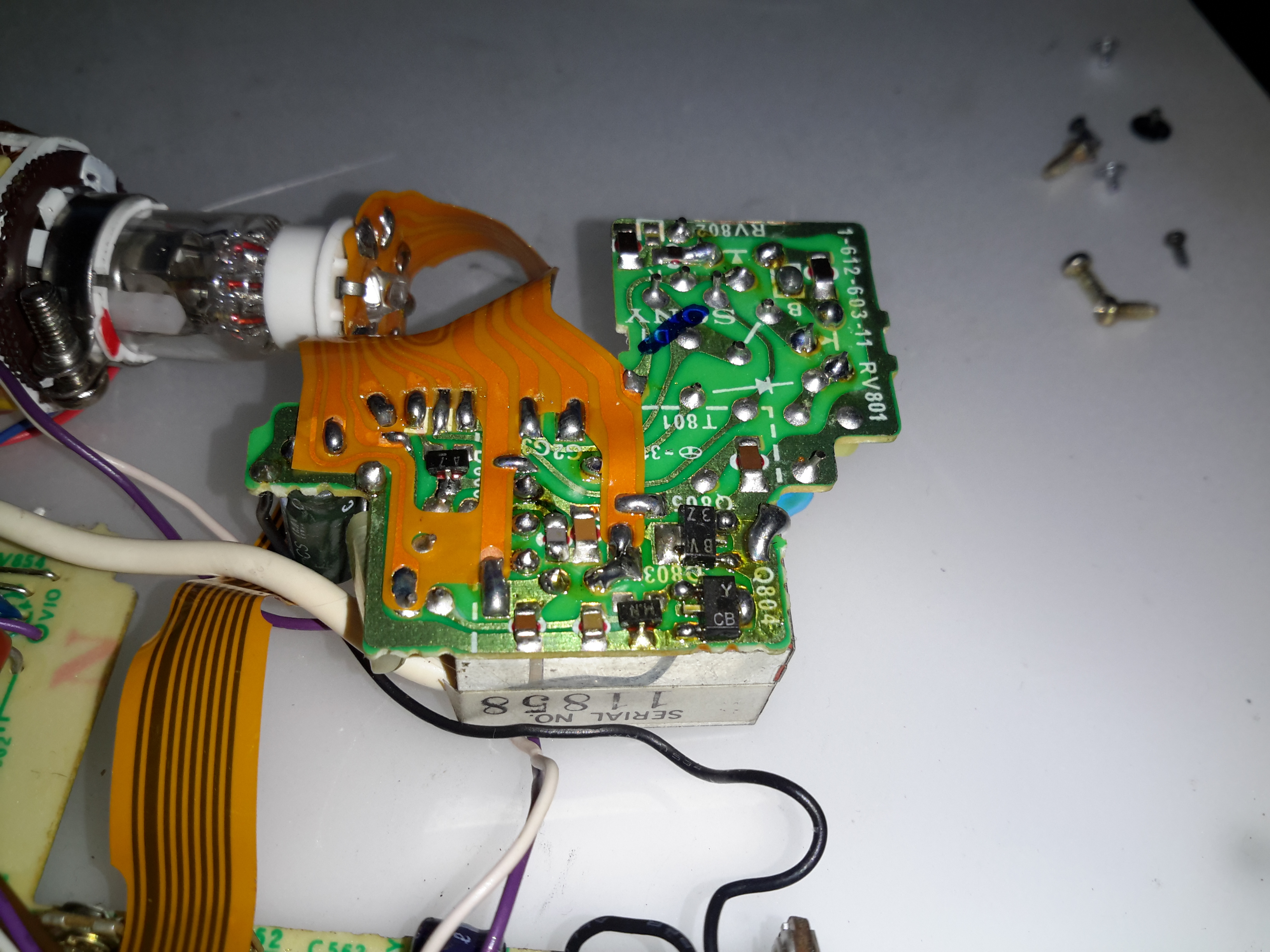
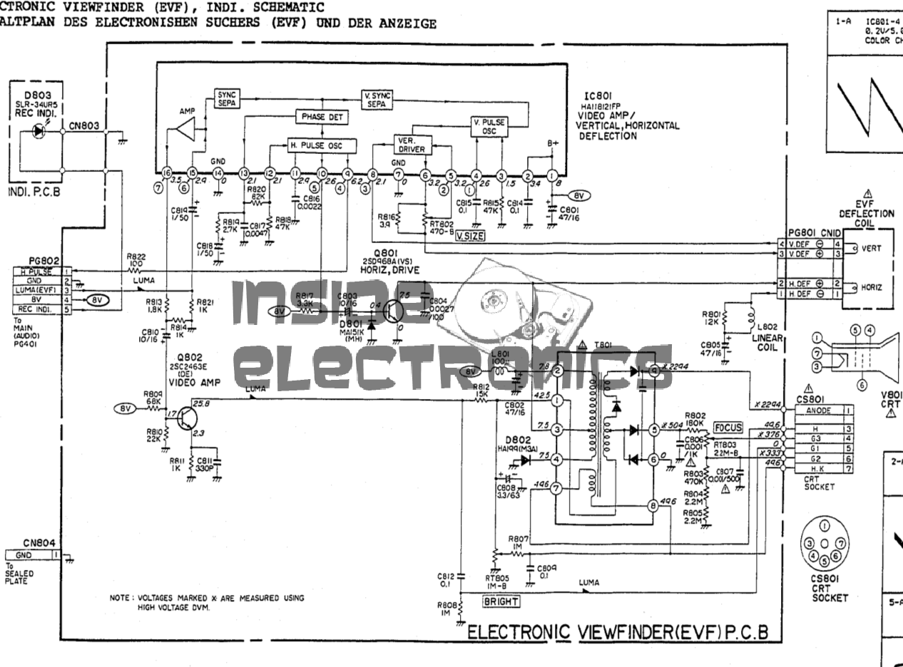
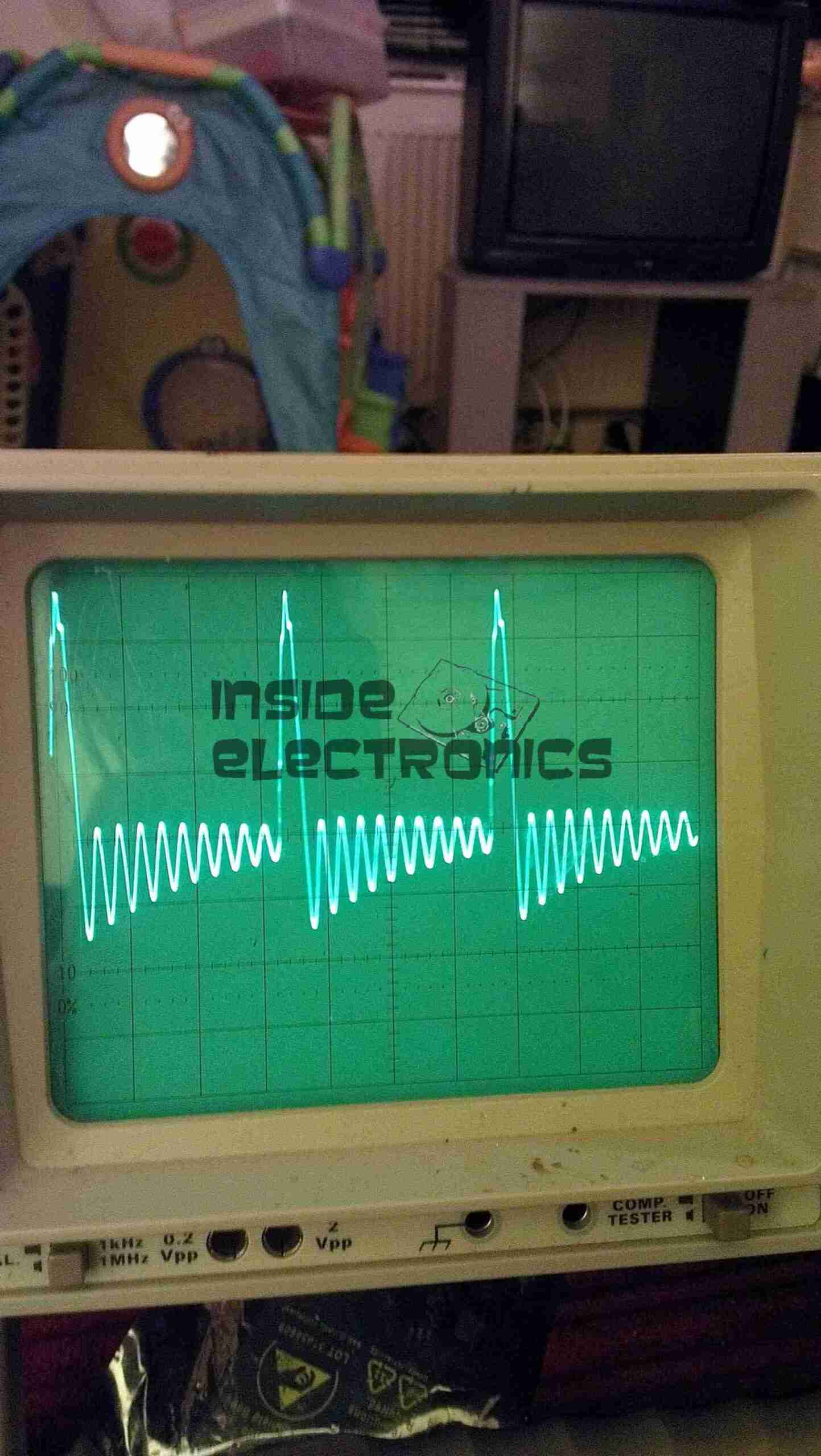
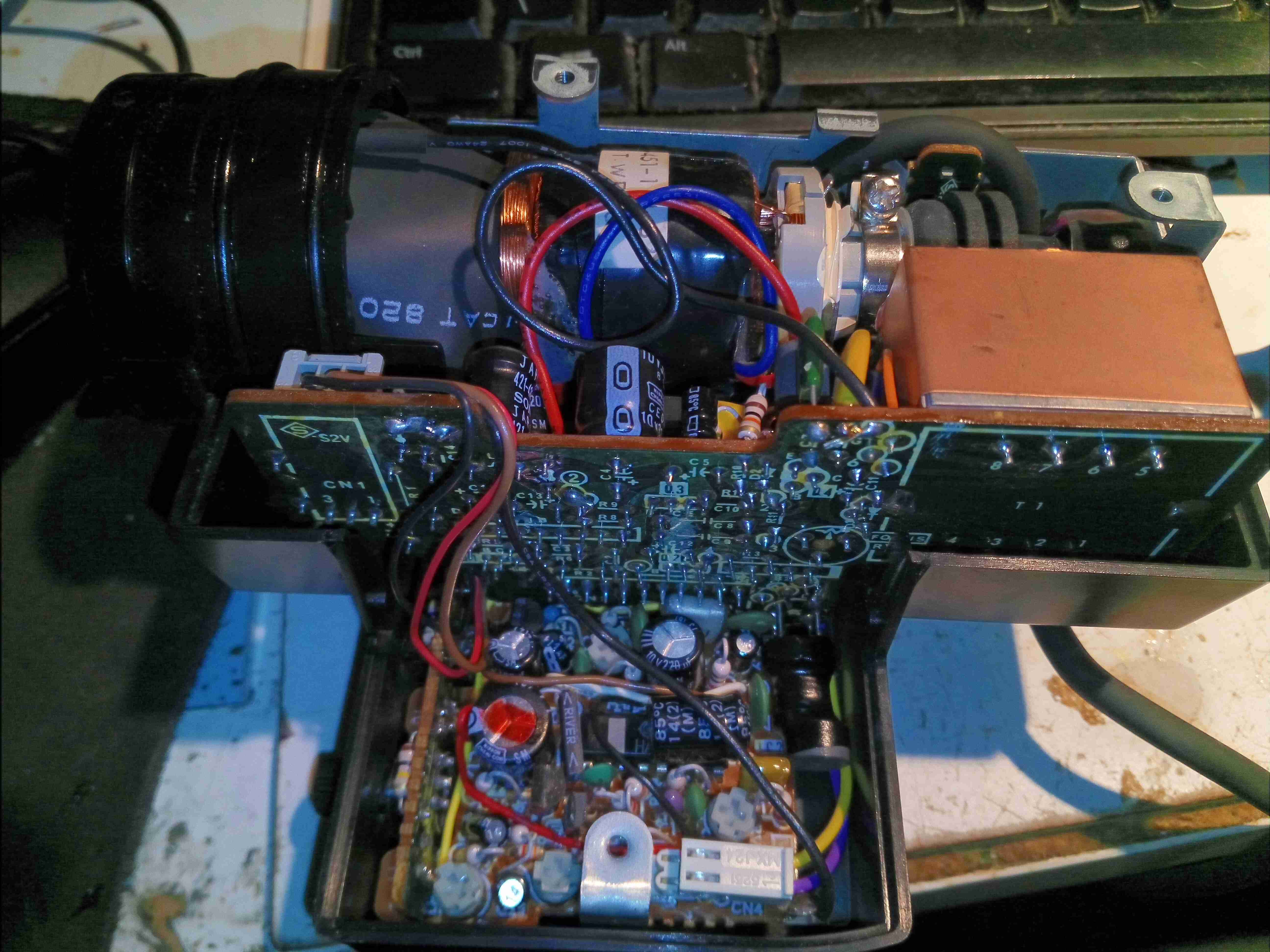
The bottom board in the assembly has all the control circuitry for the CRT, including the HA11244 deflection IC, composite sync separator & vertical deflection drive circuit. There are also circuits here to display a video waveform on the CRT, along with iris & white balance markers.

Horizontal Board
Horizontal Board

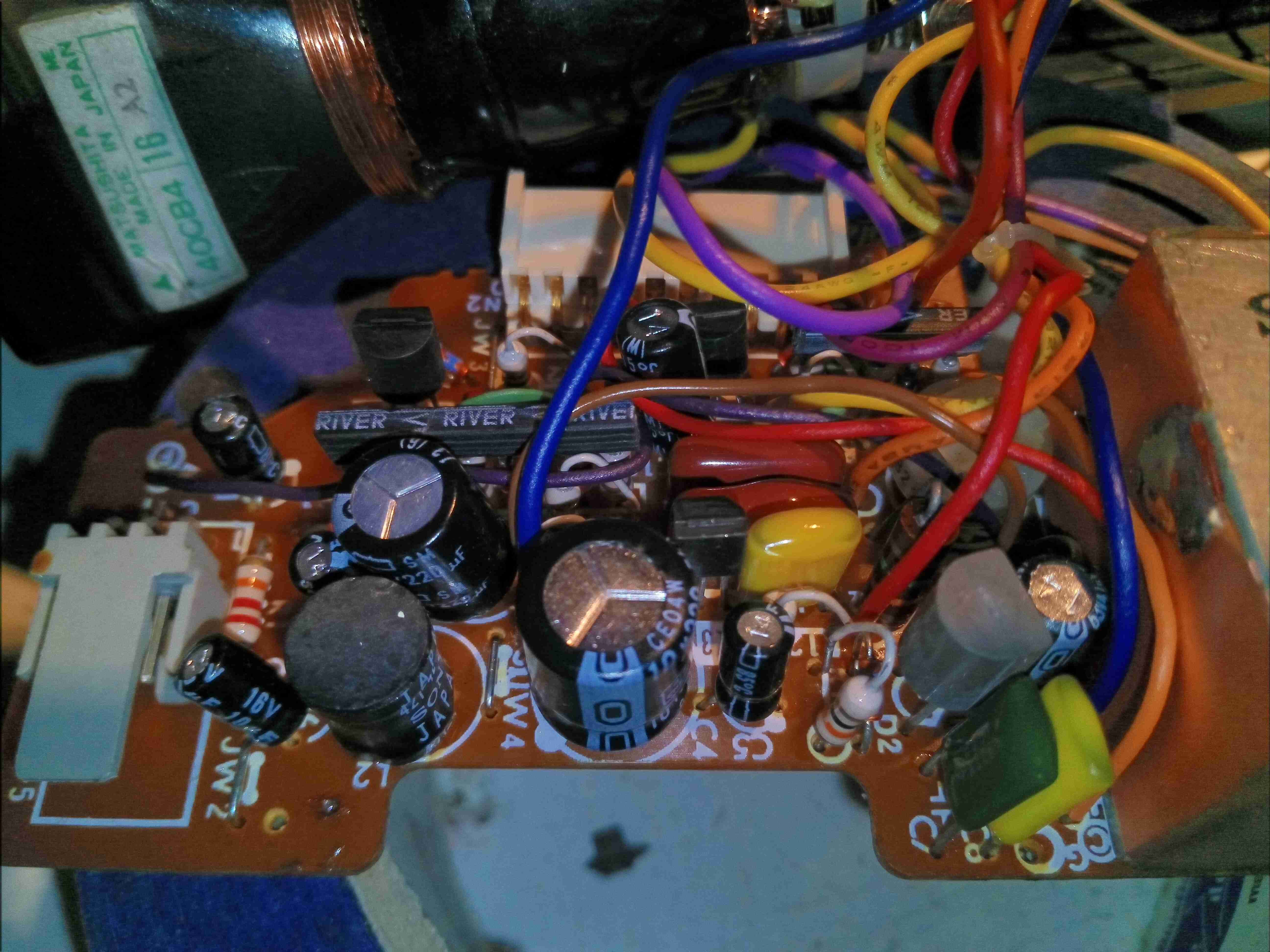
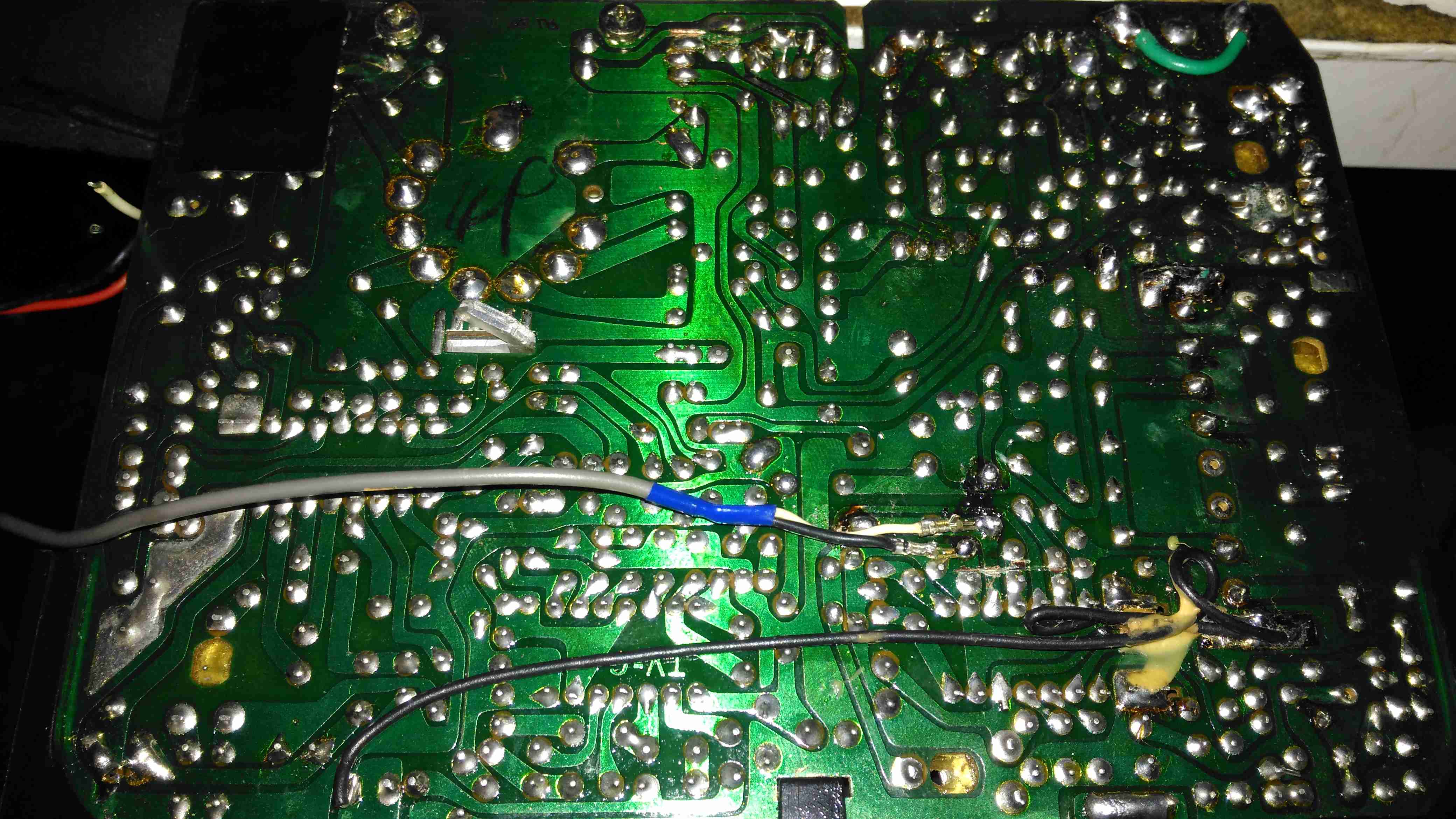
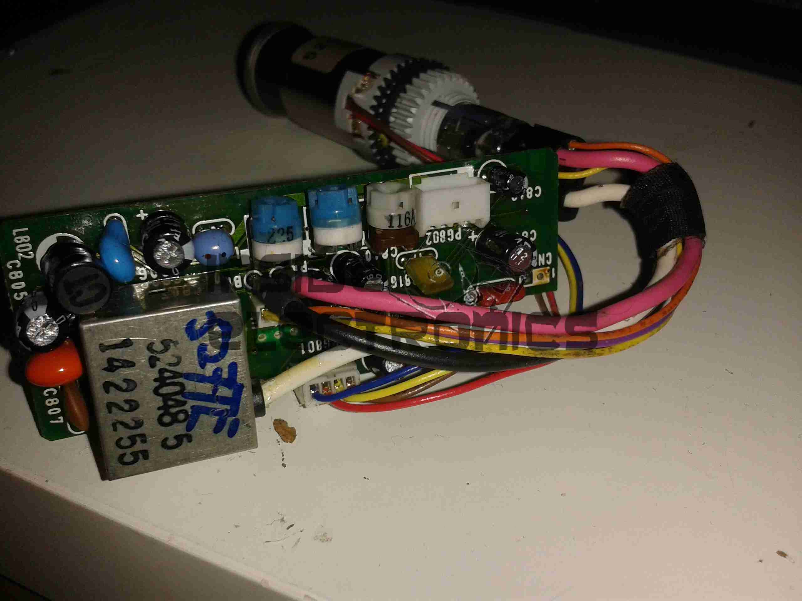
The other board has the horizontal drive circuitry, along with the video input amplifier. Despite the attempt to miniaturize the entire assembly, these are still well packed boards. Some of the resistors & diodes are bussed together in custom SIL hybrid modules to save PCB space. Like all the other CRT viewfinders, these units are meant for viewing via a mirror – the horizontal deflection coil connections need to be reversed to show a correct image without the mirror. The Red & Blue wires to the yoke need to be swapped here.

Flyback Transformer
Flyback Transformer

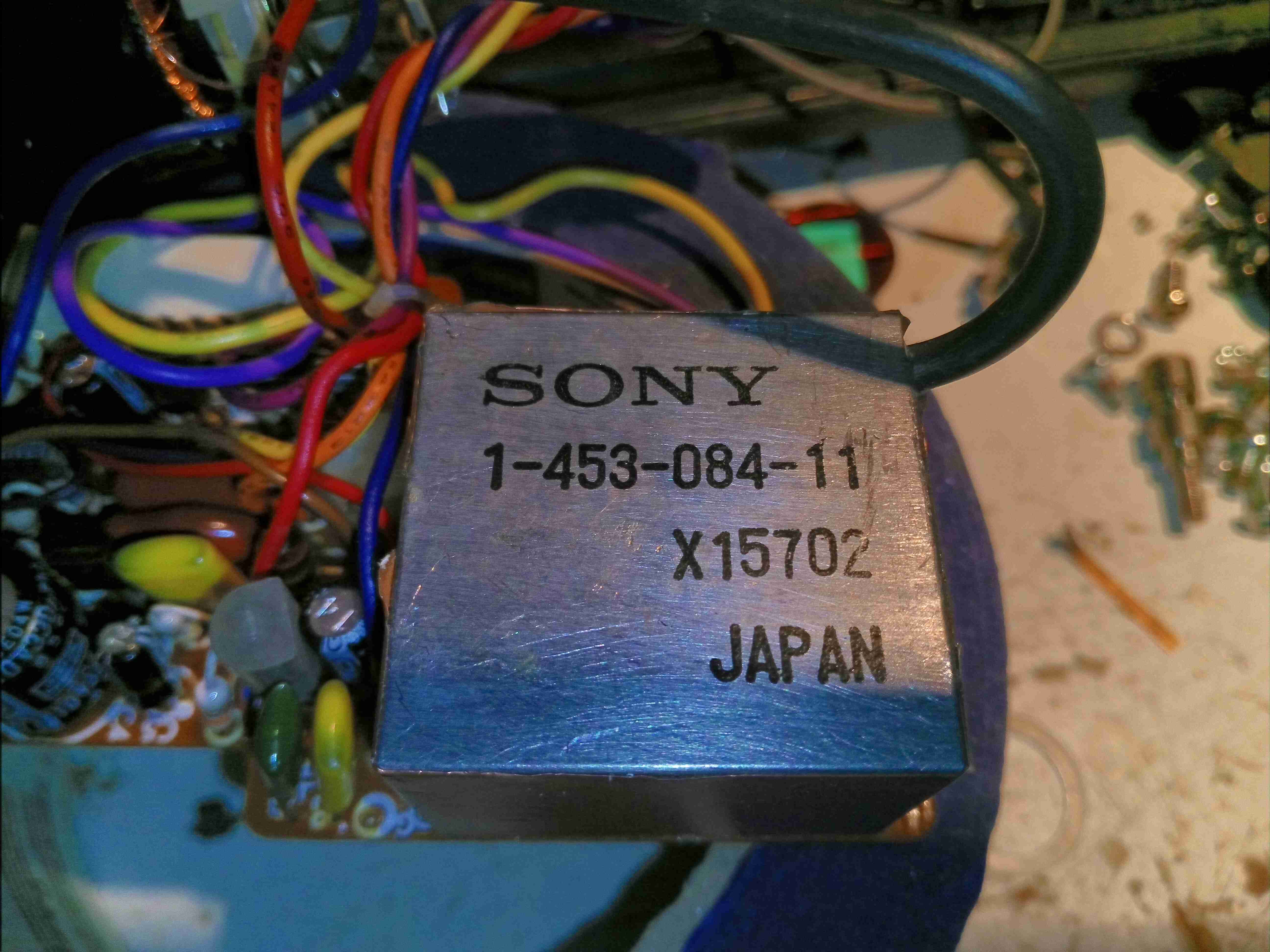
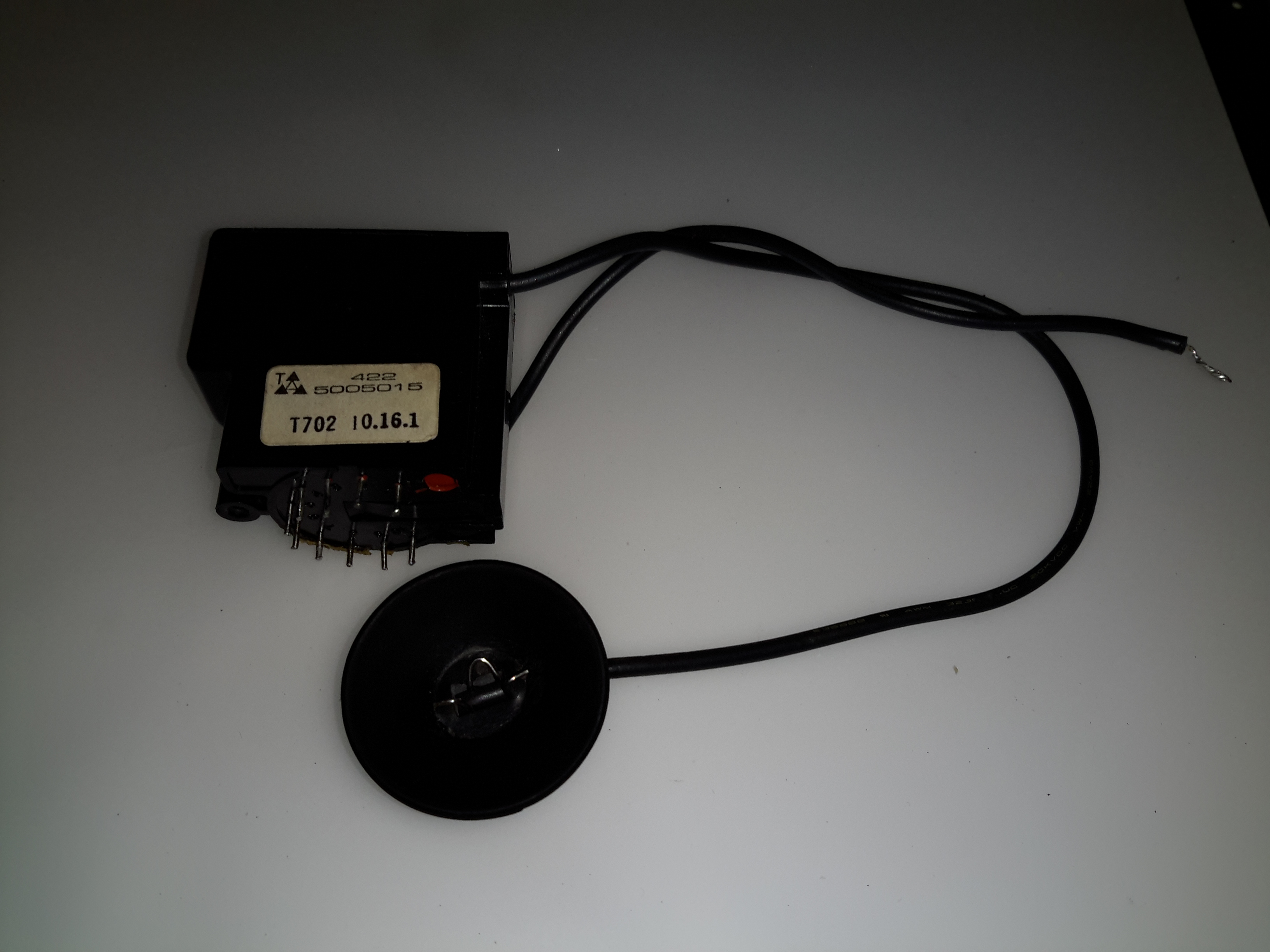
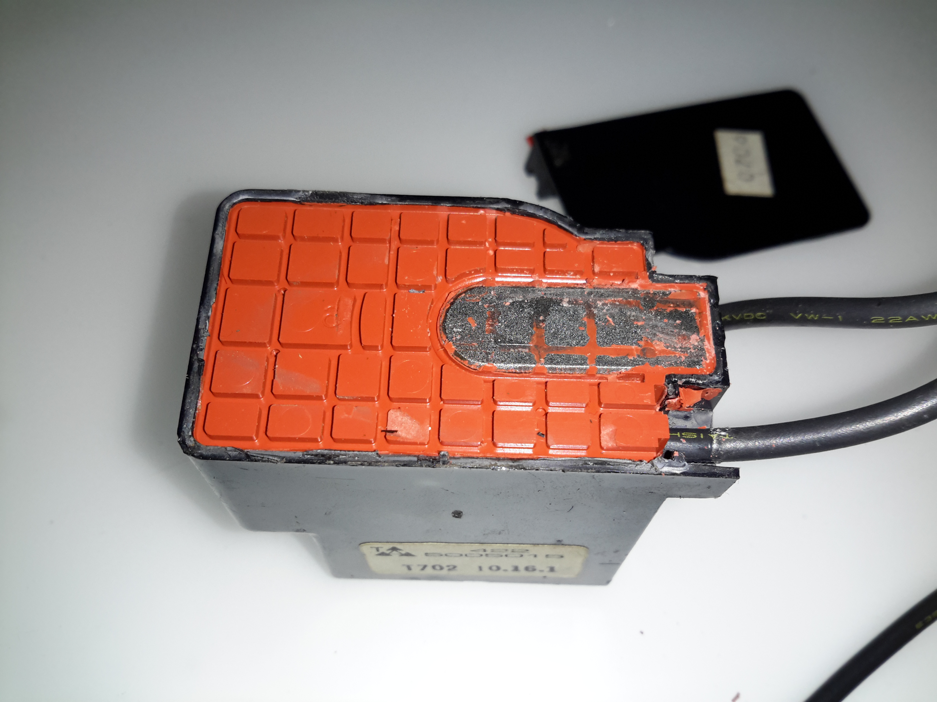
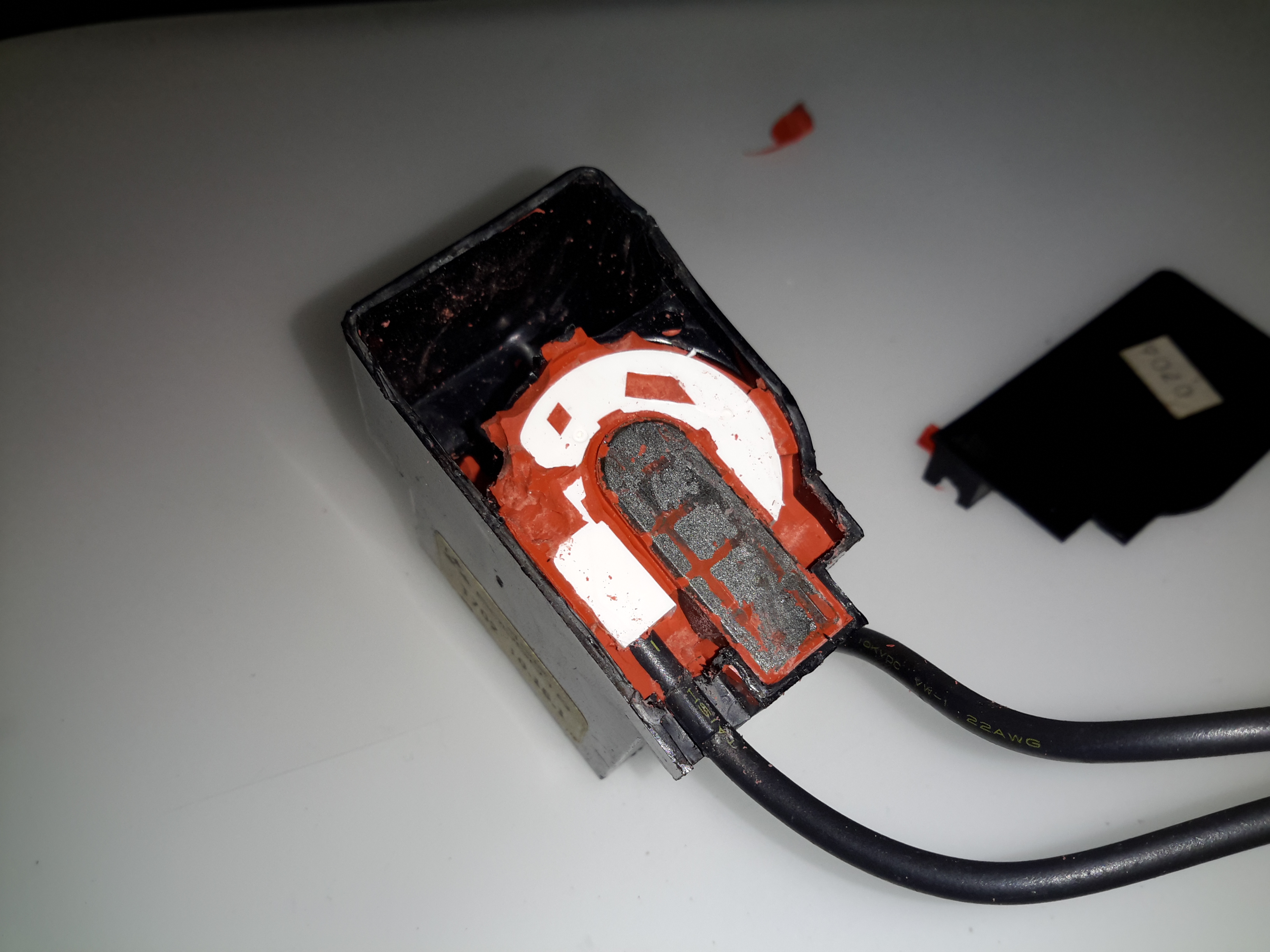
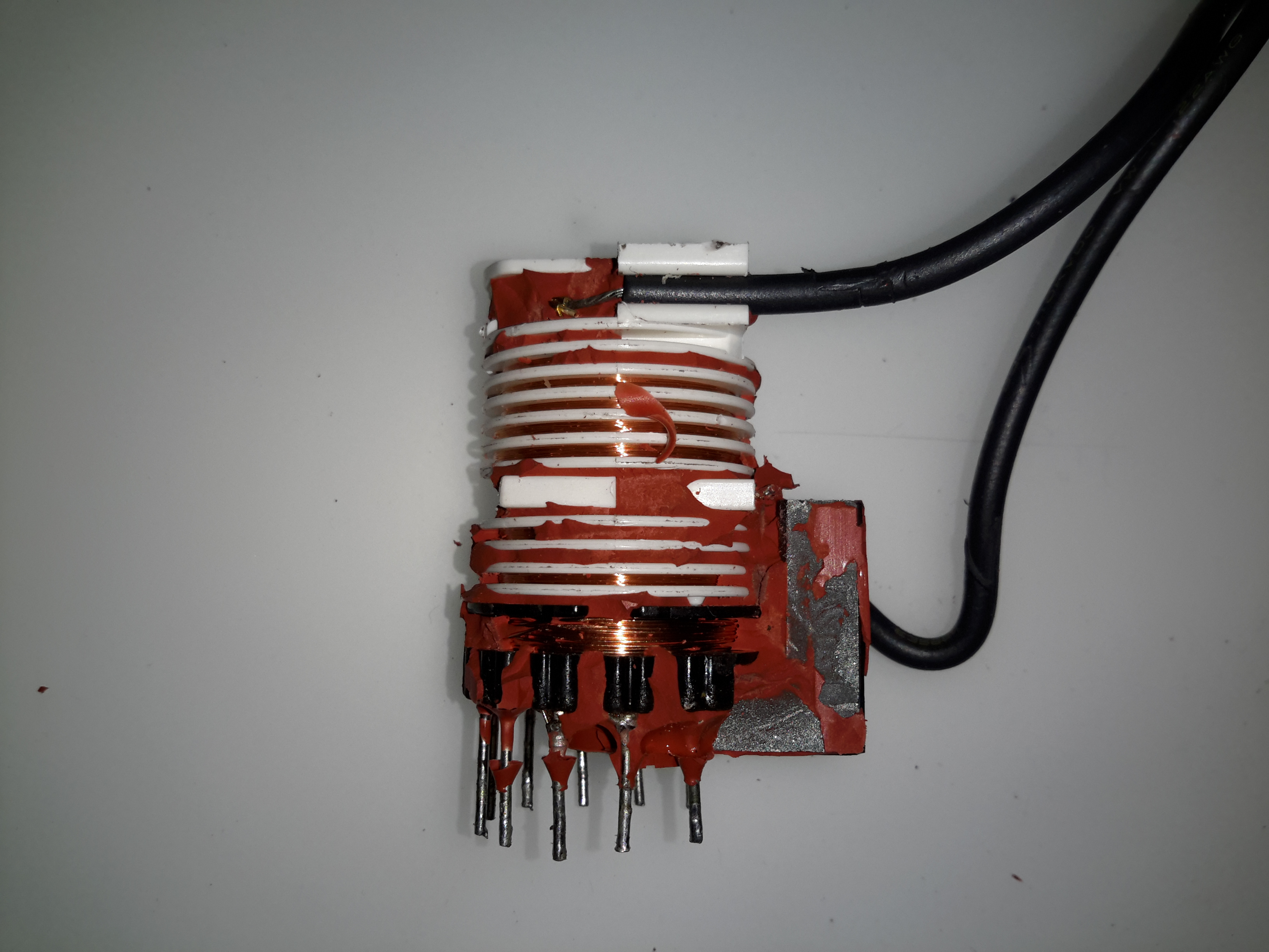
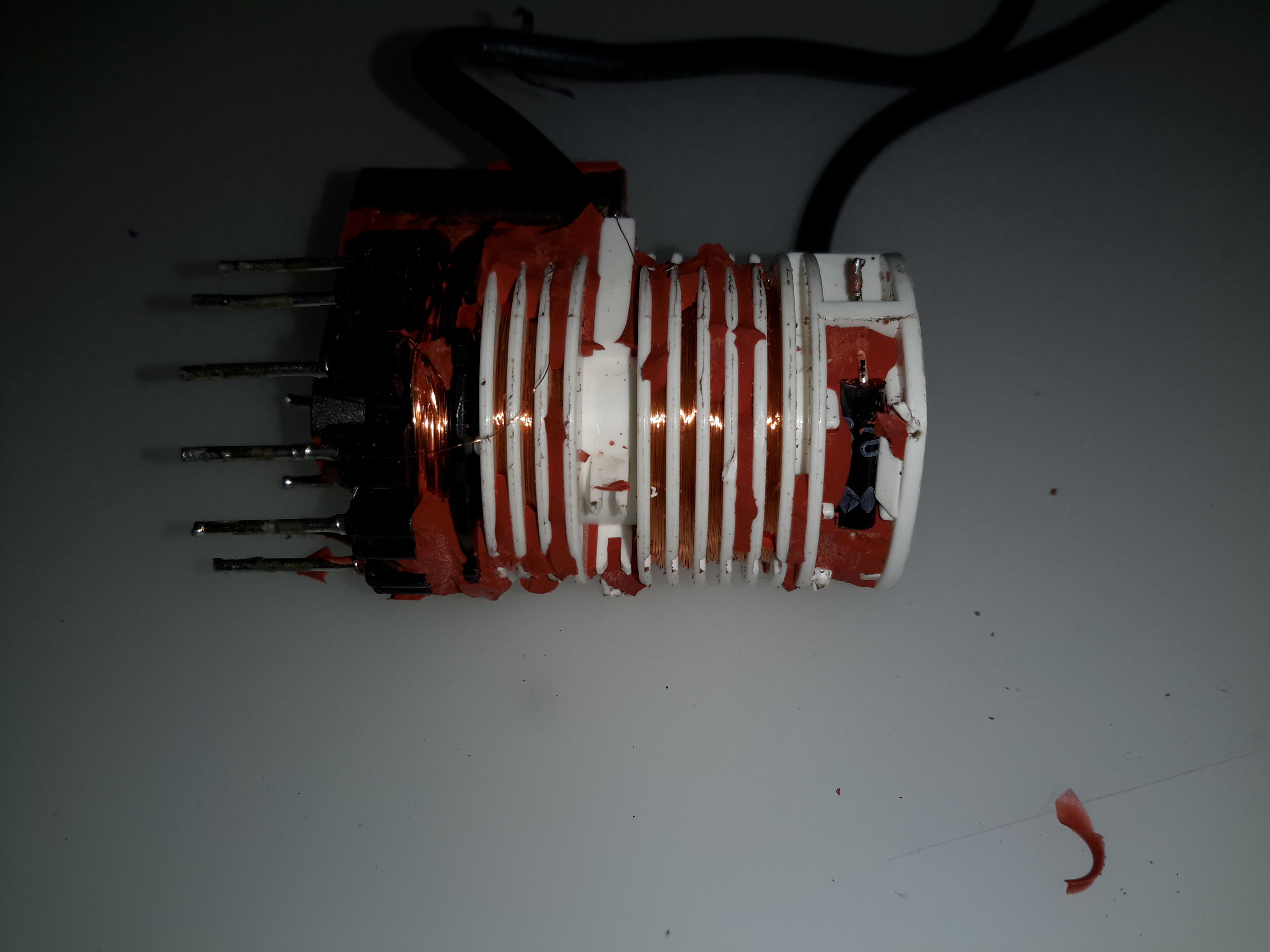
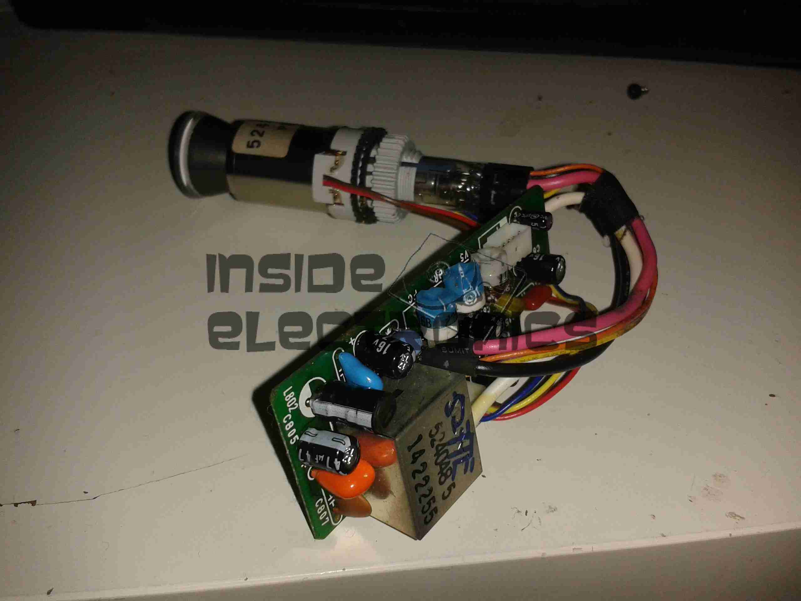
The horizontal board on this unit also supports the flyback transformer, which is massive compared to the other viewfinder circuits. Biasing, focus & filament supplies for the CRT are also derived from this transformer, via auxiliary windings.

Boards Connected
Boards Connected

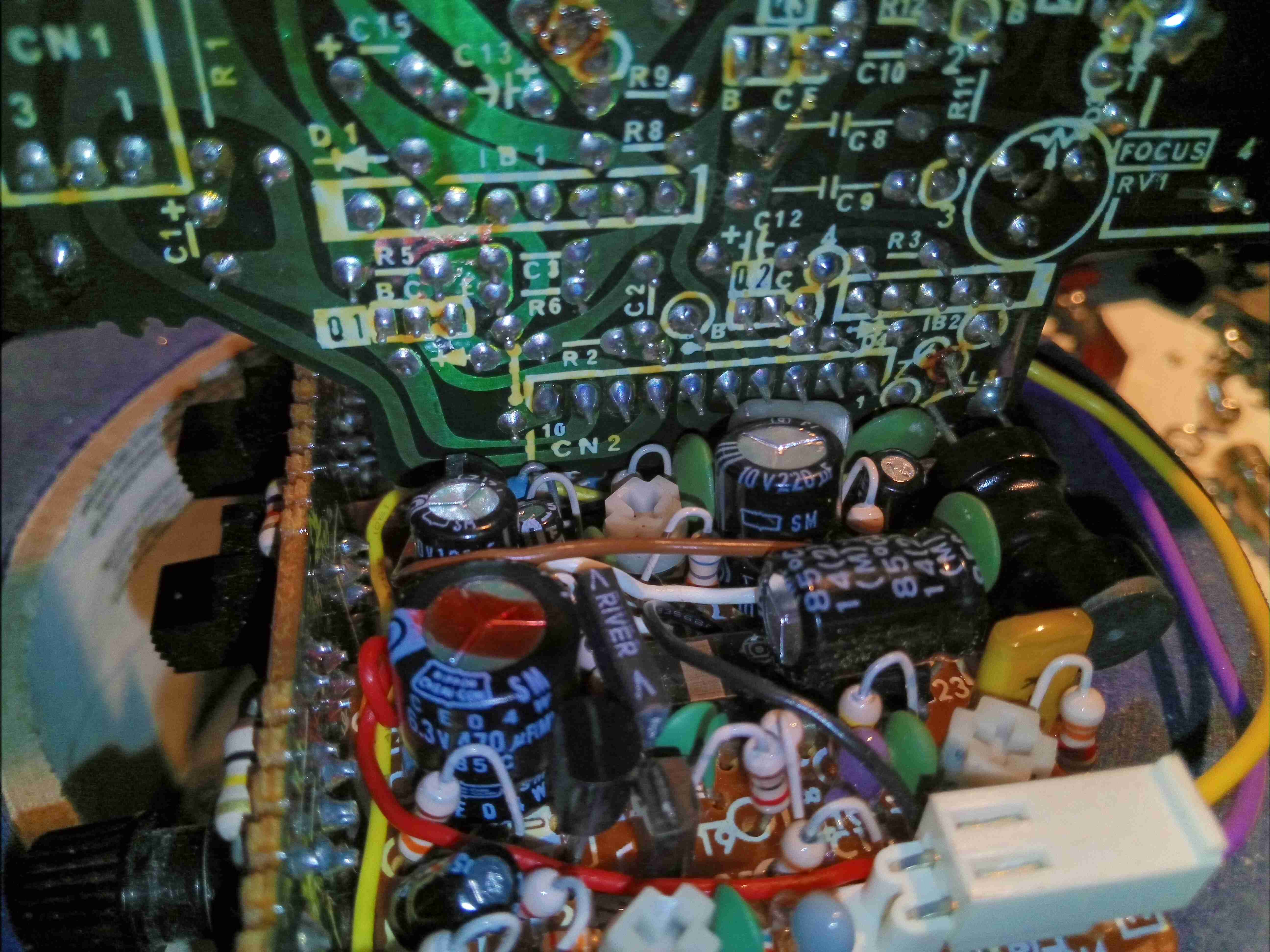
The boards slot together in the centre to form the fully operational circuit.

Video Input
Video Input

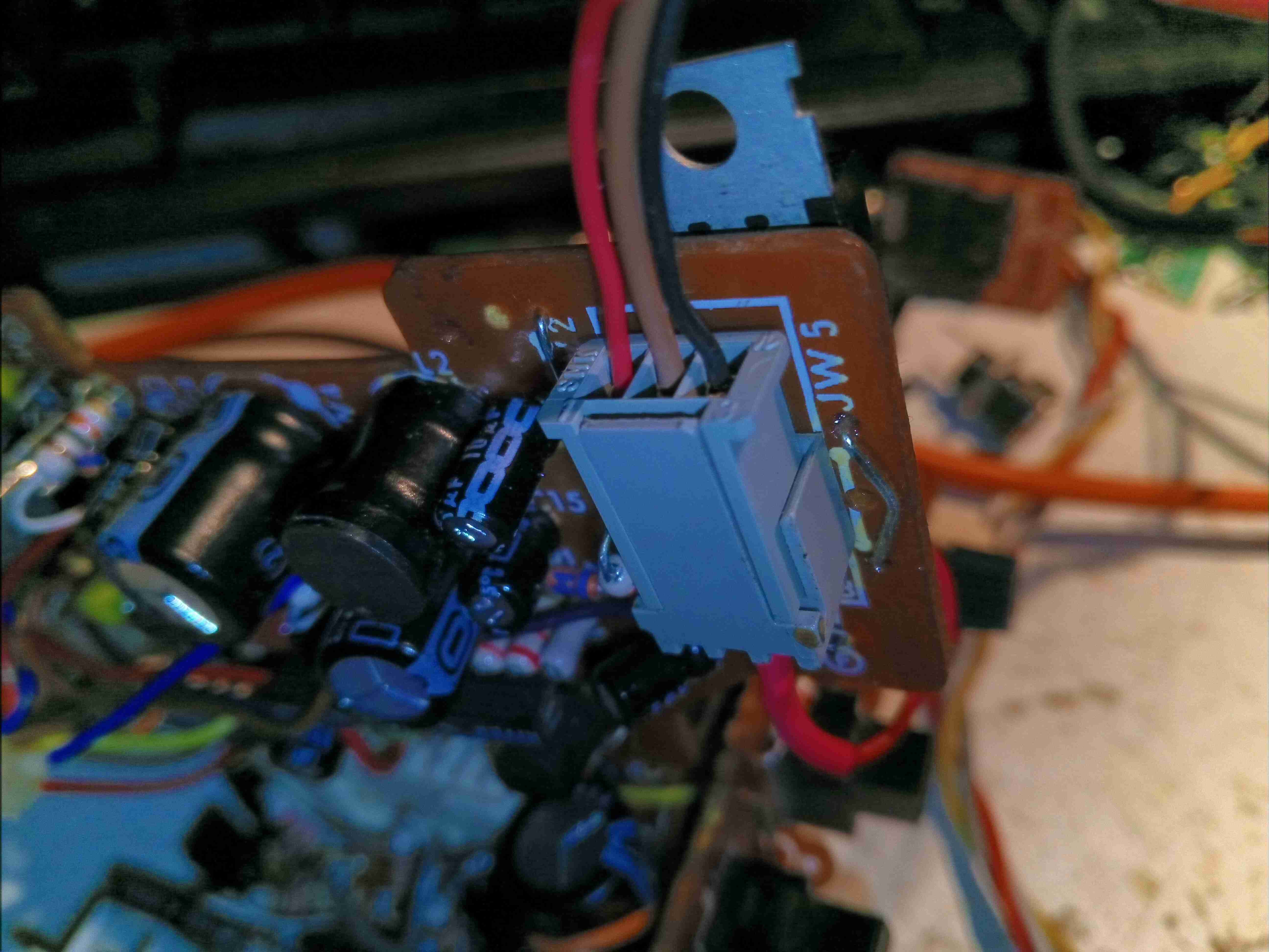
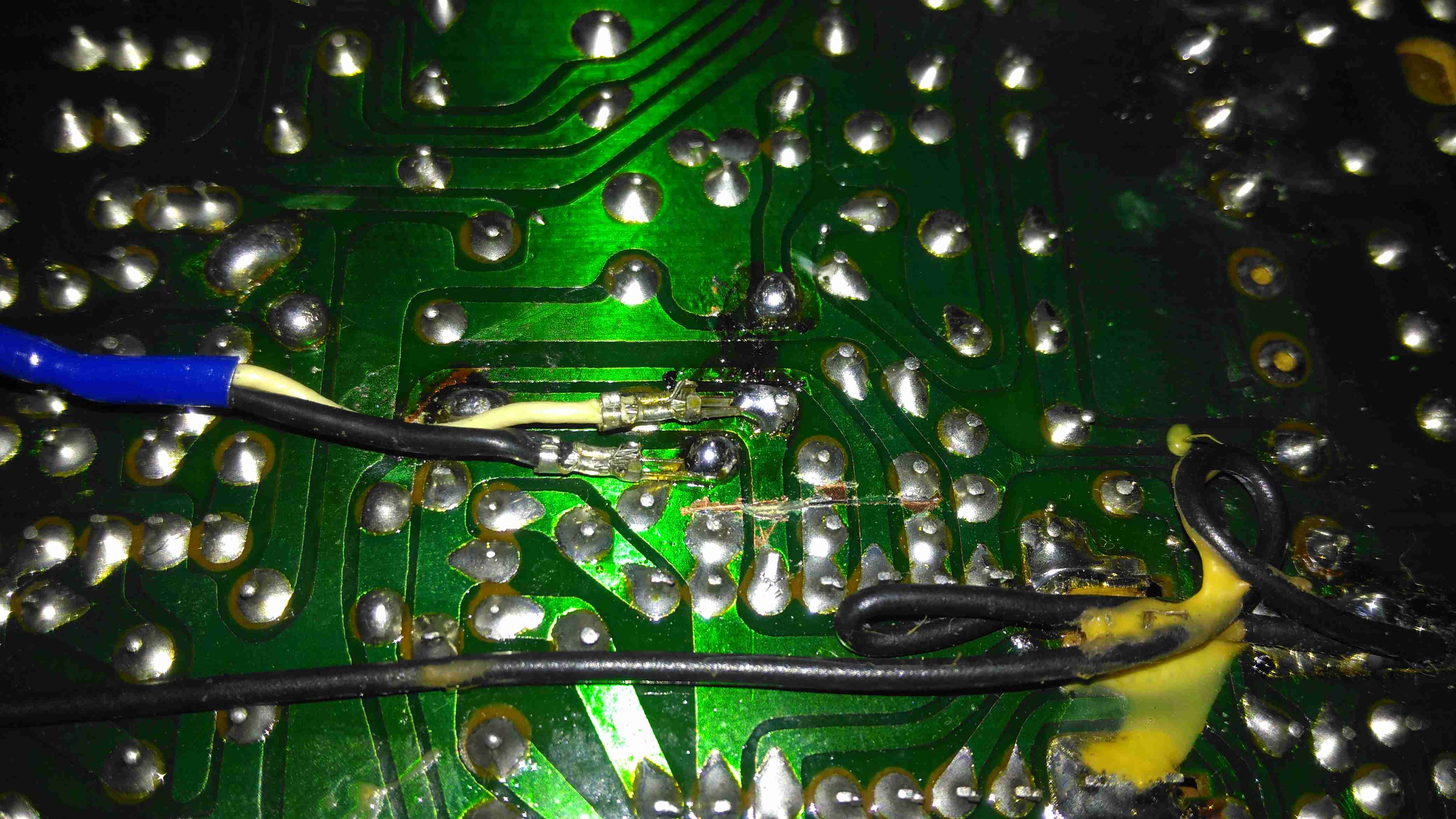
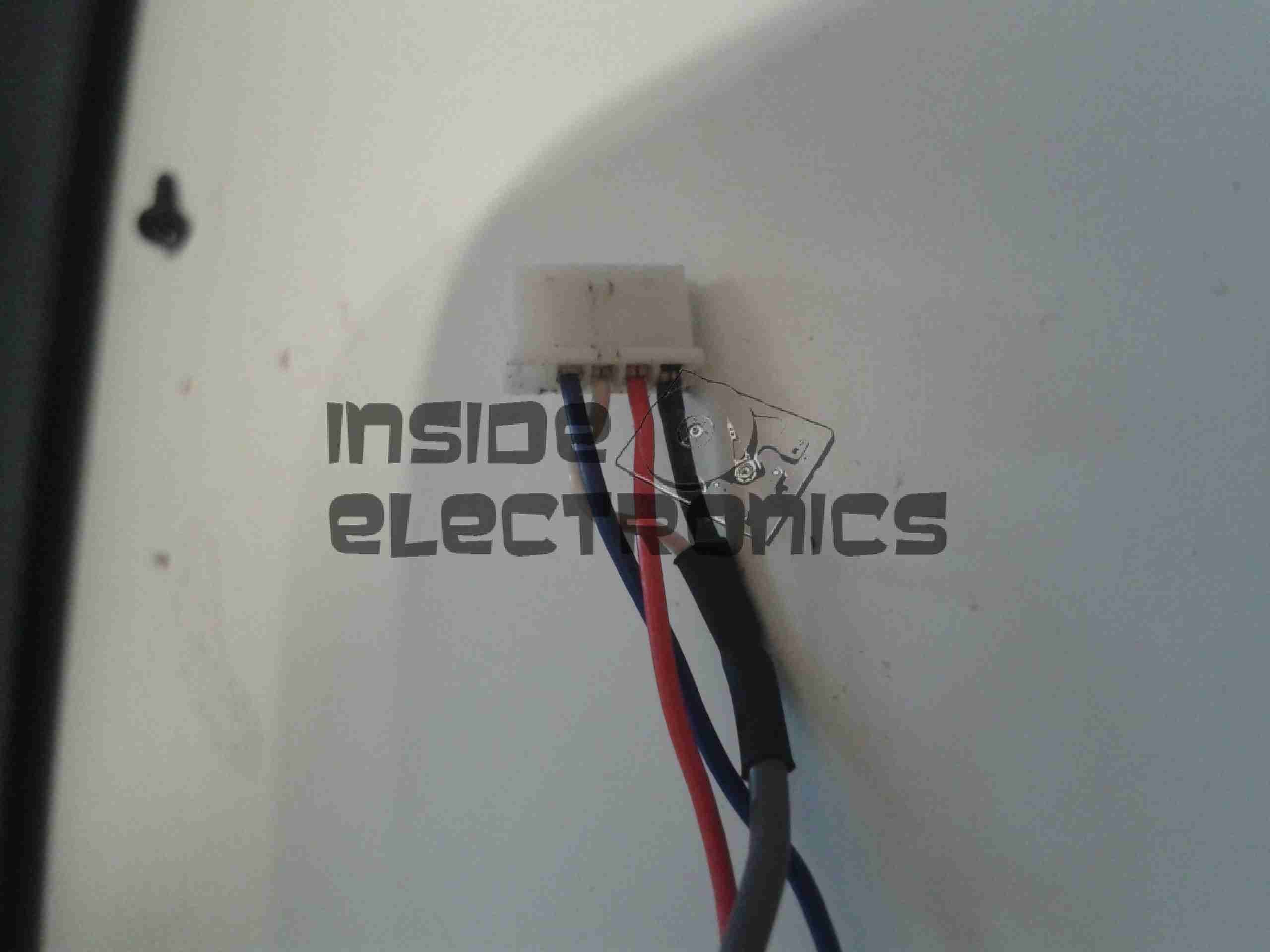
Out of the 3 plugs emerging from the cable feeding the viiewfinder, only this one is important, on the horizontal drive board. Black is ground, Brown +8.5v & red is composite video input. There’s also a resistor tied into the positive rail to the video input pin, which pulls it high to 8.5v – this is R1 right next to this connector. Desolder this 22K resistor to help protect anything feeding a signal into the unit, like a RPi, it’s not needed for normal operation.

Fallout!
Fallout!

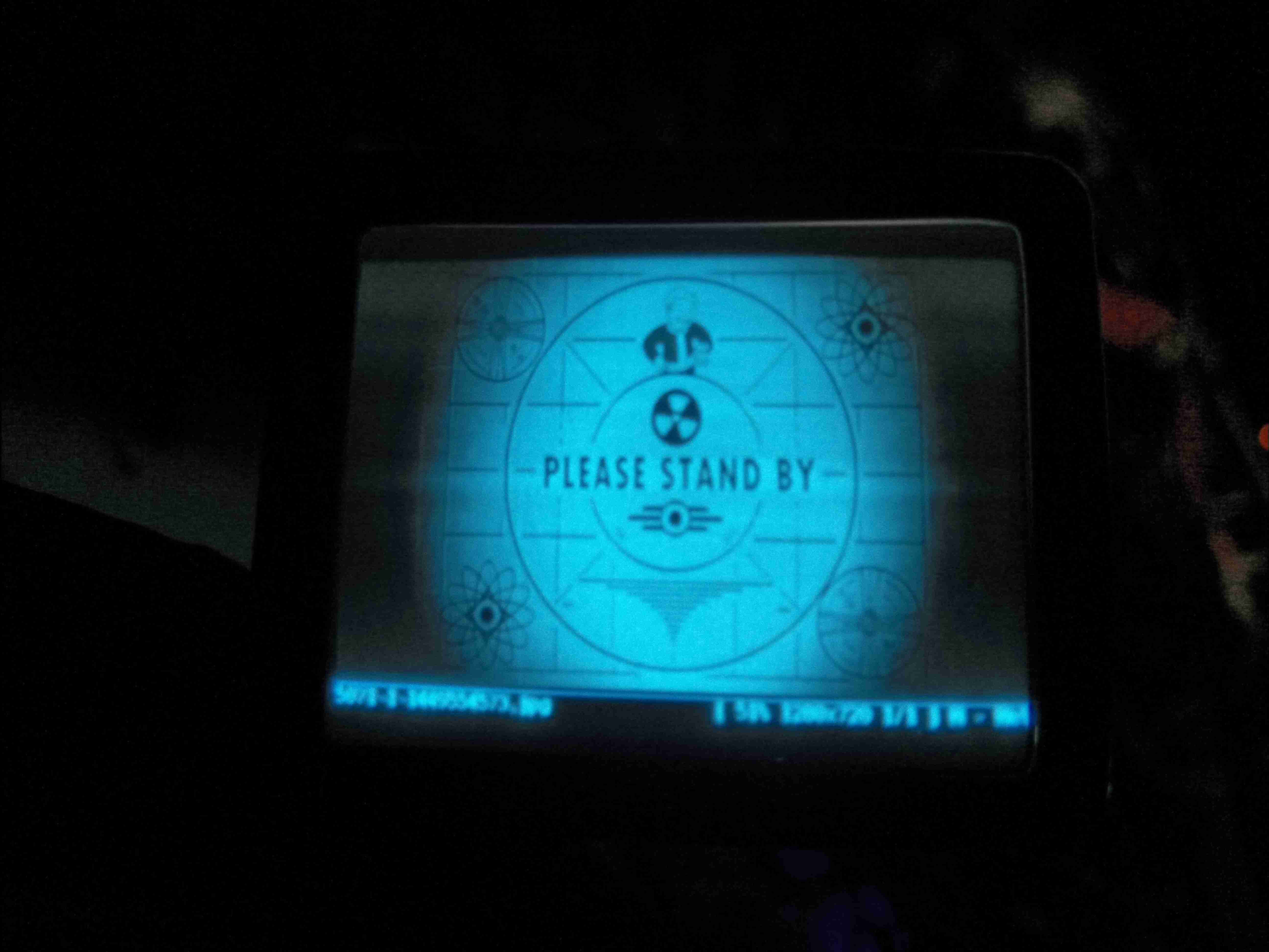
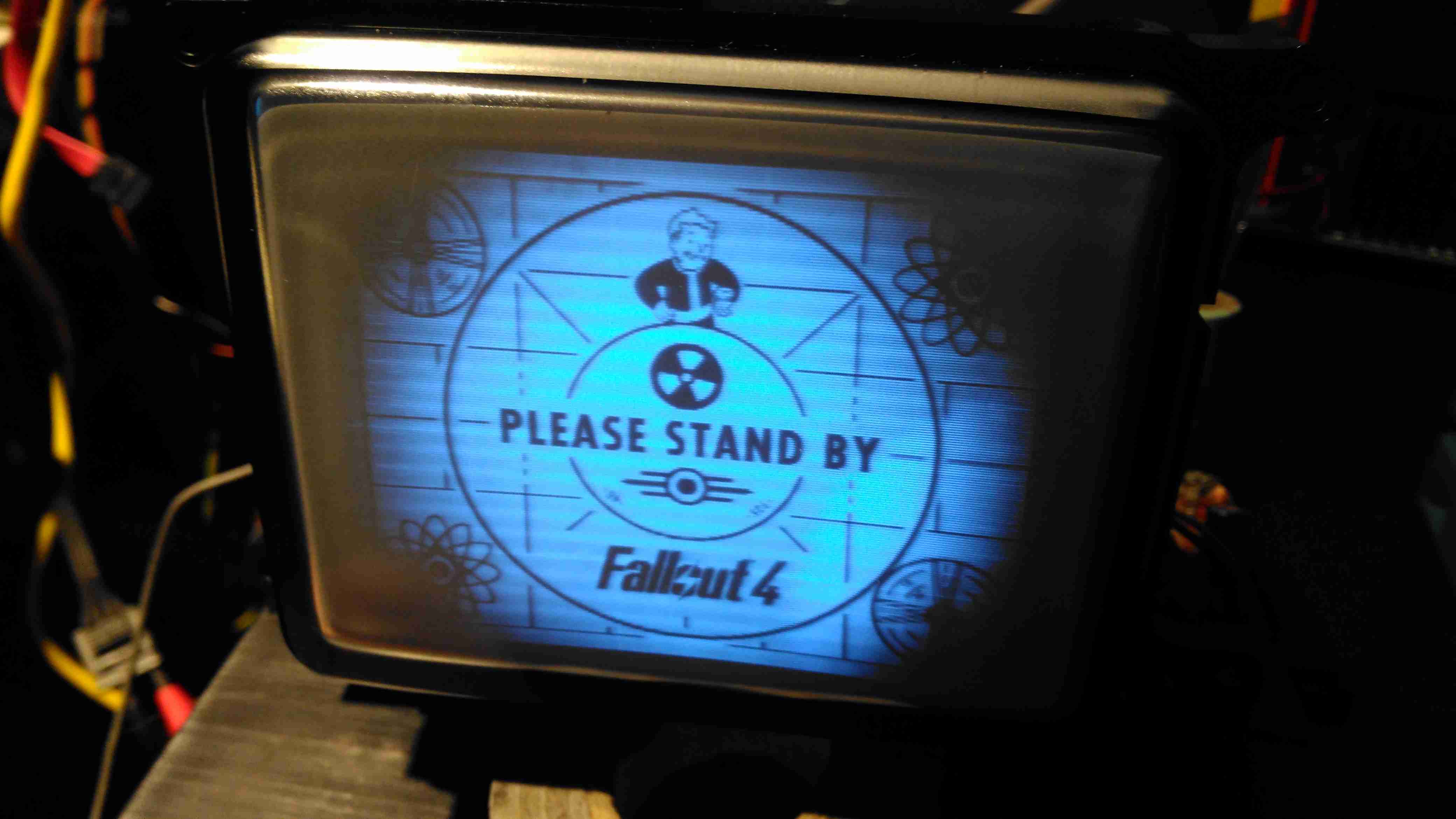
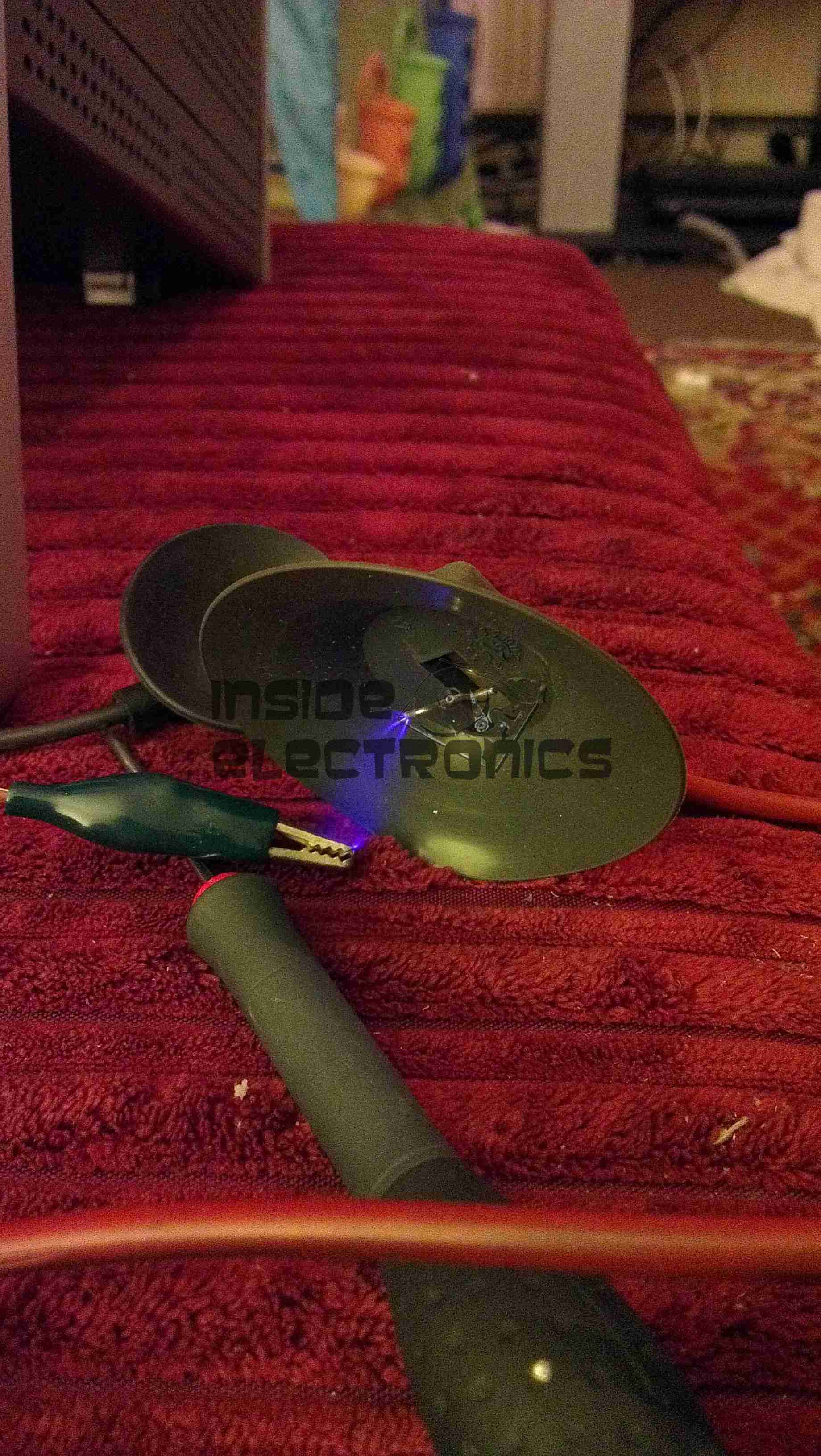
As usual for a CRT post, the Fallout loading screen on the display. The picture quality isn’t as good as it should be, probably due to the noisy buck-converter I have rigged up for testing. If it doesn’t get better with a linear regulator, I’ll start replacing the 39 year old electrolytic capacitors. Current draw is 130mA at 7.5v. Schematics for this unit & the CRT datasheet are available below:


Posted on 2 Comments

Goodmans Quadro 902 Composite Video Mod

CRT Module
CRT Module

Here’s the CRT & it’s drive board removed from the main chassis. Nicely modular this unit, all the individual modules (radio, tape, TV), are separate. This is effectively a TV itself, all the tuner & IF section are onboard, unlike in other vintage units I’ve modified, where the tuner & IF has been on a separate board. There’s a 3-pin header bottom centre for the tuning potentiometer, and external antenna input jack. The internal coax for the built in antenna has been desoldered from the board here. here a the usual controls on the back for adjusting brightness, contrast & V Hold, all the other adjustments are trimmers on the PCB.
Unfortunately after 30+ years of storage, this didn’t work on first power up, neither of the oscillators for vertical or horizontal deflection would lock onto the incoming signal, but a couple of hours running seemed to improve things greatly. The numerous electrolytic capacitors in this unit were probably in need of some reforming after all this time, although out of all of them, only 21 are anything to do with the CRT itself.

Anode Cap
Anode Cap

Here’s the anode side of the unit, with the small flyback transformer. The rubber anode cap has become very hard with age, so I’ll replace this with a decent silicone one from another dead TV. The Horizontal Output Transistor (a 2SC2233 NPN type) & linearity coil are visible at the bottom right corner of the board. Unfortunately, the disgusting yellow glue has been used to secure some of the wiring & large electrolytics, this stuff tends to turn brown with age & become conductive, so it has to be removed. Doing this is a bit of a pain though. It’s still a little bit flexible in places, and rock hard in others. Soaking in acetone softens it up a little & makes it easier to detach from the components.

Neck PCB
Neck PCB

There’s little on the neck board apart from a few resistors, forming the limiting components for the video signal, and the focus divider of 1MΩ & 470KΩ feeding G3. No adjustable focus on this unit. There’s also a spark gap between the cathode line & ground, to limit the filament to cathode voltage. The flyback transformer is nestled into the heatsink used by the horizontal output transistor & a voltage regulator transistor.

Tube Details
Tube Details

The CRT is a Samsung Electron Devices 4ADC4, with a really wide deflection angle. It’s a fair bit shorter than the Chinese CRT I have which is just a little larger, with a neck tube very thin indeed for the overall tube size.
Unusually, while the filament voltage is derived from the flyback transformer as usual, it’s rectified into DC in this unit, passing through a 1Ω resistor before the filament connection. I measured 5.3v here. The glow from the filament is barely visible even in the dark.

Electron Gun 1
Electron Gun 1

The electron gun is the usual for a monochrome tube, with 7 pins on the seal end.

Electron Gun 2
Electron Gun 2

The electrodes here from left are Final Anode, G3 (Focus Grid), Accelerating Anode, G2 (Screen Grid), G1 (Control Grid). The cathode & filament are hidden inside G1. In operation there’s about 250v on G2, and about 80v on G3.

Chipset
Chipset

The chipset used here is all NEC, starting with a µPC1366C Video IF Processor, which receives the IF signal from the tuner module to the left. This IC outputs the standard composite signal, and a modulated sound signal.
This then splits off to a µPC1382C Sound IF Processor & Attenuator IC, which feeds the resulting sound through the two pin header at the right bottom edge of the board to the audio amplifier in the chassis.
The composite video signal is fed through a discrete video amplifier with a single 2SC2229 transistor before going to the CRT cathode.
The remaining IC is a µPC1379C Sync Signal Processor, containing the sync separator, this is generating the required waveforms to drive the CRT deflection systems from another tap off the composite video line.
From this chip I can assume the unit was built around 1986, since this is the only date code on any of the semiconductors. Besides these 3 ICs, the rest of the circuit is all discrete components, which are well-crammed into the small board space.
There are 5 trimmer potentiometers on the board here, I’ve managed to work out the functions of nearly all of them:

  • SVR1: IF Gain Adjust
  • SVR2: H. Hold
  • SVR3: V. Size
  • SVR4: B+ Voltage Adjust
  • SVR5: Tuner Frequency Alignment? It’s in series with the tuning potentiometer in the chassis.
PCB Bottom
PCB Bottom

The PCB bottom shows the curved track layout typical of a hand taped out board. The soldermask is starting to flake off in places due to age, and there a couple of bodge wires completing a few ground traces. Respinning a board in those days was an expensive deal! Surprisingly, after all this time I’ve found no significant drift in the fixed resistors, but the carbon track potentiometers are drifiting significantly – 10KΩ pots are measuring as low as 8KΩ out of circuit. These will have to be replaced with modern versions, since there are a couple in timing-sensitive places, like the vertical & horizontal oscillator circuits.

Anode Cap Replaced
Anode Cap Replaced

Here the anode cap has been replaced with a better silicone one from another TV. This should help keep the 6kV on the CRT from making an escape. This was an easy fix – pulling the contact fork out of the cap with it’s HT lead, desoldering the fork & refitting with the new cap in place.

Here I’ve replaced the important trimmers with new ones. Should help stabilize things a little.

Composite Injection Mod

Injecting a video signal is as easy as the other units. Pin 3 of the µPC1366C Video IF Processor is it’s output, so the track to Pin 3 is cut and a coax is soldered into place to feed in an external signal.

CRT In Operation
CRT In Operation

After hooking up a Raspberry Pi, we have display! Not bad after having stood idle for 30+ years.

Datasheets for the important ICs are available below:
[download id=”5690″]
[download id=”5693″]
[download id=”5696″]

Posted on 2 Comments

CRT Flyback / Line Output Transformer Destructive Teardown

Small Flyback Transformer

Here’s a small flyback / Line Output Transformer from a portable colour TV set. Usually these transformers are vacuum potted in hard epoxy resin & are impossible to disassemble without anything short of explosives. (There are chemical means of digesting cured epoxies, but none of them are pleasant). This one however, was potted in silicone, so with some digging, the structure of the transformer can be revealed.

Cap Removed
Cap Removed

The cap was glued on to the casing, but this popped off easily. The top of the core is visible in the silicone potting material.

The Digging Starts
The Digging Starts

A small screwdriver was used to remove the potting material, while trying not to damage the winding bobbin & core too badly. The bulge in the casing that I originally thought might house a voltage multiplier turns out to be totally empty. The white plastic bobbin is becoming visible around the core.

Bobbin
Bobbin

After some more digging & a lot of mess later, the entire transformer is revealed. The primary & auxiliary secondaries are visible at the bottom of the transformer, next to the pins. These transformers have multiple windings, as they’re used not only for supplying the final anode voltage of several Kilovolts to the CRT, but many of the other associated voltages, for the heater, grids, focus electrodes, etc. These lower voltage windings are on the same part of the core as the primary.
Above those is the main high voltage secondary winding, which looks to be wound with #38-#40AWG wire (about the thinnest available, at 0.07mm diameter. This is wound in many sections of of a few hundred turns each to increase the insulation resistance to the high voltage. The main anode wire emerges from the top of the bobbin.

Output Rectifier
Output Rectifier

Hidden in a recess at the top is the main HV rectifier, which on this small transformer is a single device (it’s probably not internally, most likely a series stack of diodes to get the PIV rating required).

Posted on 6 Comments

Sony Watchman FD-20 Flat CRT TV Teardown

Sony Watchman FD-20
Sony Watchman FD-20

Here’s an oddity from the 1980’s – a CRT-based portable TV, with a very strangely shaped tube. Sony produced many types of flat CRTs back in the 80’s, with the electron gun at 90° to the curved phosphor screen.

Front Panel
Front Panel

The front panel has the display window, along with the tuning & volume indicators. Unfortunately since analogue TV transmissions have long been switched off, this unit no longer picks up any transmissions off the air, but it can be modified to accept a composite video input.

Back Panel
Back Panel

The back panel has the battery compartment & the tilt stand.

Certification
Certification

The certification label reveals this unit was manufactured in May 1984, 32 years ago!

Spec. Label
Spec. Label

Rated at 6v, ~2.1W this device uses surprisingly little power for something CRT based.

Battery Holder
Battery Holder

The battery holder is a little unique, this plastic frame holds 4 AA cells, for a 6v pack.

Battery Compartment
Battery Compartment

The battery holder slots into the back of the TV, there’s also an extra contact that the service manual mentions is for charging, so I assume a rechargeable 6v battery pack was also available.

Front Panel Removed
Front Panel Removed

Removing a pair of pin-spanner type screws allows the front glass & screen printed CRT surround to be removed. Not much more under here other than the pair of screws that retain the CRT in the front frame.

Back Cover Removed
Back Cover Removed

Here’s the back cover removed, after unscrewing some very small screws. As per usual with Sony gear, the electronics is extremely compacted, using many flat flex cables between the various PCBs. The main PCB is visible at the back, this has all the deflection circuitry, RF tuner, Video IF, Audio IF, video amplifier & composite circuitry.

CRT Electron Gun & Flyback Transformer

Lifting up the main board reveals more PCBs – the high voltage section for the CRT with the flyback transformer, focus & brightness controls is on the left. The loudspeaker PCB is below this. The CRT electron gun is tucked in behind the flyback transformer, it’s socket being connected to the rest of the circuitry with a flat flex cable.

CRT Rear
CRT Rear

Here’s the back of the CRT, the phosphor screen is on the other side of the curved glass back. These tubes must require some additional deflection complexity, as the geometry will change as the beam scans across the screen. There’s a dynamic focus circuit on the schematics, along with extensive keystone adjustments.

Sony 02-JM Flat CRT
Sony 02-JM Flat CRT

Here’s the tube entirely extracted from the chassis. The EHT connection to the final anode is on the side of the tube bell, the curved phosphor screen is clearly visible. The one thing I can’t find in this CRT is a getter spot, so Sony may have a way of getting a pure enough vacuum that one isn’t required.

I’d expect the vertical deflection waveforms to be vastly different on this kind of CRT, due to the strange screen setup. Not much of a beam movement is required to move the spot from the top to the bottom of the screen.

HV Module
HV Module

No doubt to keep the isolation gaps large, all the high voltages are kept on a separate small PCB with the flyback transformer. This board generates the voltages for the electron gun filament, focus grid & the bias to set the beam current (brightness) as well.

Bare CRT
Bare CRT

Here the deflection yoke has been removed from the CRT, showing the very odd shape better. These tubes are constructed of 3 pieces of glass, the bell with electron gun, back glass with phosphor screen & front viewing window glass. All these components are joined with glass frit.

Electron Gun
Electron Gun

The electron gun in the neck looks to be pretty much standard, with all the usual electrodes.

Viewing Window
Viewing Window

Here’s a view from the very top of the CRT, the curve in the screen is very obvious here. The electron beam emerges from the bell at the back.

FD-20 Schematic
FD-20 Schematic

Here’s the full schematic of the entire TV, I extracted this from a service manual I managed to find online.

More to come on hacking this unit to accept a standard composite video input, from something such as a Raspberry Pi!

Posted on Leave a comment

Another Viewfinder CRT

Here’s another viewfinder CRT, removed from a 1980’s vintage VHS camera I managed to get cheap from eBay.

This unit is very similar to the last one I posted about, although there are a few small differences in the control circuitry.

Viewfinder Schematic
Viewfinder Schematic – Click to Embiggen

Here’s the schematic, showing all the functional blocks of the viewfinder circuitry. An integrated viewfinder IC is used, which generates all the required scan waveforms for the CRT.
On the left is the input connector, with the power & video signals. Only pins 2 (GND), 3 (Composite video), & 4 (+8v) are needed here. Pin 1 outputs a horizontal sync signal for use elsewhere in the camera, while pin 5 fed the recording indicator LED.

To make connection easier,  I have rearranged the wires in the input connector to a more understandable colour scheme:

Input Connector
Input Connector

Red & Blue for power input, & a coax for the video. For the video GND connection, I have repurposed the Rec. LED input pin, putting a shorting link across where the LED would go to create a link to signal ground. Keeping this separate from the power GND connection reduces noise on the CRT.

Viewfinder CRT Assembly

Here’s the complete assembly liberated from it’s plastic enclosure.

PCB Closeup
PCB Closeup

Closeup of the control PCB. The 3 potentiometers control the CRT brightness, focus & vertical size.

M01KGG007WB CRT
M01KGG007WB CRT

The tiny CRT. Only ~60mm in length, with an 18mm screen size. This tube runs on +2294v final anode voltage. Much higher than I expected.

Electron Gun Closeup

The electron gun assembly, with the cathode, focus & final anode cups.

Phosphor Screen
Phosphor Screen

This screen is just a little bigger than a UK 5p piece! A marvel of precision engineering.


Posted on Leave a comment

555 Flyback Driver

Flyback Secondary Waveform
Board Layout
Board Layout

Here is a simple 555 timer based flyback transformer driver, with the PCB designed by myself for some HV experiments. Above is the Eagle CAD board layout.

The 555 timer is in astable mode, generating a frequency from about 22kHz to 55kHz, depending on the position of the potentiometer. The variable frequency is to allow the circuit to be tuned to the resonant frequency of the flyback transformer in use.

This is switched through a pair of buffer transistors into a large STW45NM60 MOSFET, rated at 650v 45A.

Input power is 15-30v DC, as the oscillator circuit is fed from an independent LM7812 linear supply.

Provision is also made on the PCB for attaching a 12v fan to cool the MOSFET & linear regulator.

Initial Board
Initial Board

Board initially built, with the heatsink on the linear regulator fitted. I used a panel mount potentiometer in this case as I had no multiturn 47K pots in stock.

PCB Traces
PCB Traces

Bottom of the PCB. The main current carrying traces have been bulked up with copper wire to help carry the potentially high currents on the MOSFET while driving a large transformer.
This board was etched using the no-peel toner transfer method, using parchement paper as the transfer medium.

MOSFET Heatsinked
MOSFET Heatsinked

Main MOSFET now fitted with a surplus heatsink from an old switchmode power supply. A Fan could be fitted to the top of this sink to cope with higher power levels.

Gate Drive Waveform
Gate Drive Waveform

This is the gate drive waveform while a transformer is connected, the primary is causing some ringing on the oscillator. The waveform without an attached load is a much cleaner square wave.

Flyback Secondary Waveform

I obtained a waveform of the flyback secondary output by capacitively coupling the oscilloscope probe through the insulation of the HT wire. The pulses of HV can be seen with the decaying ringing of the transformer between cycles.

Corona Discharge
Corona Discharge
Arc Discharge
Arc Discharge

Corona & arc discharges at 12v input voltage.

Download the Eagle schematic files here: [download id=”5561″]

Posted on 10 Comments

Camcorder CRT Viewfinder

CRT Assembly
CRT Assembly

Here are the viewfinder electronics from a 1984 Hitachi VHS Movie VM-1200E Camcorder. These small CRT based displays accept composite video as input, plus 5-12v DC for power.

Screen
Screen

Here is the front face of the CRT, diameter is 0.5″.

Power Board
Power Board

Closeup view of the PCB, there are several adjustments & a pair of connectors. Socket in the upper left corner is the power/video input. Pinout is as follows:

  1. Brown – GND
  2. Red – Video Input
  3. Orange – +12v DC
  4. Yellow – Record LED
The potentiometers on the PCB from left:
  1. H. ADJ
  2. V. ADJ
  3. BRIGHT
  4. FOCUS
PCB Part Number reads: EM6-PCB
This unit utilises the BA7125L deflection IC.
Solderside
Solderside
Reverse side of the PCB, very few SMT components on this board.
Tube Assembly
Tube Assembly
Here is an overall view of the CRT assembly with scan coils. Tube model is NEC C1M52P45.
Electron Gun
Electron Gun

Closeup view of the CRT neck, showing the electron gun assembly.


CCTV Camera
CCTV Camera

The old CCTV camera used to feed a composite signal to the CRT board. Sanyo VCC-ZM300P.

CCTV Camera Connections

Connections at the back of the camera. Red & Black pair of wires lead to 12v power supply, Green & Black pair lead to the CRT board’s power pins. Seperate green wire is pushed into the BNC video connector for the video feed. video ground is provided by the PSU’s ground connection.

Connections
Connections

Finally the connections at the CRT drive board, left to right, +12v, Video, GND.

Screen Operation
Screen Operation

Display taking video signal from the CCTV camera.