Posted on Leave a comment

Turbine Fuel Pump Extreme Teardown

Turbine Fuel Pump
Turbine Fuel Pump

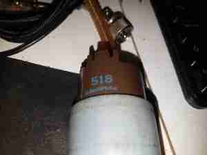
Here’s a destructive teardown of an automotive in-tank turbine fuel pump, used on modern Petrol cars. These units sit in the tank fully immersed in the fuel, which also circulates through the motor inside for cooling. These pumps aren’t serviceable – they’re crimped shut on both ends. Luckily the steel shell is thin, so attacking the crimp joint with a pair of mole grips & a screwdriver allowed me inside.
End Bell
End Bell

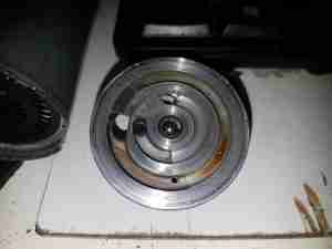
The input endbell of the pump has the fuel inlet ports, the channels are visible machined into the casting. There’s a pair of channels for two pump outputs – the main fuel rail to the engine, and an auxiliary fuel output to power a venturi pump. The fuel pump unit sits inside a swirl pot, which holds about a pint of fuel. These are used to ensure the pump doesn’t run dry & starve the engine when the tank level is low & the car is being driven hard. The venturi pump draws fuel from the main tank into the swirl pot. A steel ball is pressed in to the end bell to provide a thrust bearing for the motor armature.
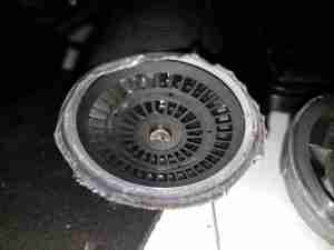
Turbine Impeller
Turbine Impeller

The core of the pump is this impeller, which is similar to a side-channel blower. From what I’ve been able to find these units supply pressures up to about 70PSI for the injector rail. The outside ring is the main fuel pump, while the smaller inner one provides the pressure to run the venturi pump.
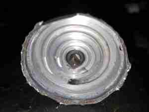
Pump Housing
Pump Housing

The other side of the machined pump housing has the main output channel, with the fuel outlet port at the bottom. The motor shaft is supported in what looks like a carbon bearing.
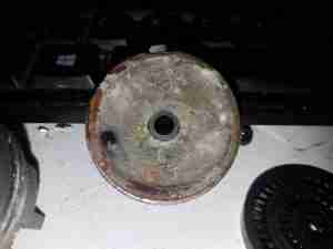
Midsection
Midsection

Removing the pump intermediate section with the bearing reveals quite a bit of fungus – it’s probably been happy sat in here digesting what remains of the fuel.
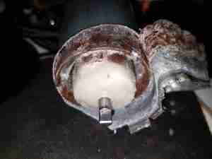
Armature Exposed
Armature Exposed

Some peeling with mole grips allows the motor to come apart entirely. The drive end of the armature is visible here.
Motor Can
Motor Can

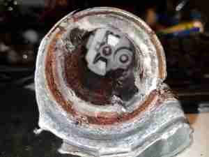
The outer shell of the motor holds yet more fungus, along with some rust & the pair of ceramic permanent magnets.
Brushes
Brushes

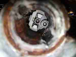
The other end of the pump has the brush assembly, and the fuel outlet check valve to the right. The bearing at this end is just the plastic end cap, since there are much lower forces at this end of the motor. The fuel itself provides the lubrication required.
Potted Armature
Potted Armature

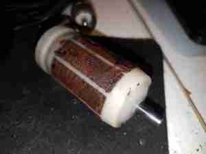
With the armature pulled out of the housing, it’s clear that there’s been quite a bit of water in here as well, with the laminations rusting away. This armature is fully potted in plastic, with none of the copper windings visible.
Carbon Commutator
Carbon Commutator

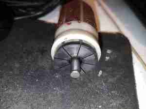
The commutator in these motors is definitely a strange one – it’s axial rather than radial in construction, and the segments are made of carbon like the brushes. No doubt this is to stop the sparking that usually occurs with brushed motors – preventing ignition of fuel vapour in the pump when air manages to get in as well, such as in an empty tank.
Posted on Leave a comment

Anker PowerPort Speed 5 12v DC Conversion

A few months ago I did a teardown on this Anker PowerPort Speed 5 USB charger, but I didn’t get round to detailing the conversion to 12v I had to do, so I’ll get to that now I’ve got a couple more to convert over.

Power Module
Power Module

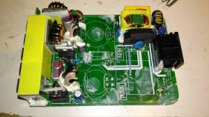
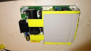
Here’s the internals of the Anker charger once I’ve removed the casing – which like many things these days, is glued together. (Joints can be cracked with a screwdriver handle without damaging the case). There’s lots of heatsinking in here to cool the primary side switching devices & the pot core transformers, so this is the first thing to get removed.

Heatsink Removed
Heatsink Removed

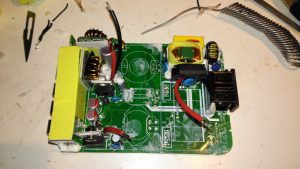
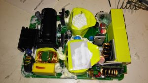
Once the heatsink has been removed, the pot core transformers are visible, wrapped in yellow tape. There’s some more heatsink pads & thermal grease here, to conduct heat better. The transformers, primary side switching components & input filter capacitor have to go.

Primary Side Components Removed

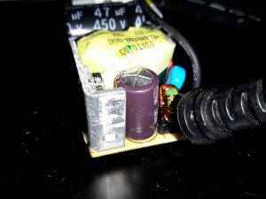
Here’s the PCB once all the now redundant mains conversion components have been deleted. I’ve left the input filtering & bridge rectifier in place, as this solves the issue of the figure-8 cable on the input being reversible, polarity of the input doesn’t matter with the bridge. I’ve removed the main filter capacitor to make enough room for the DC-DC converters to be fitted.

Tails Installed
Tails Installed

Installing the tails to connect everything together is the next step, this charger requires two power supplies – the QC3 circuits need 14.4v to supply the multi-voltage modules, the remaining 3 standard ports require 5v. The DC input tails are soldered into place where the main filter capacitor was, while the outputs are fitted to the spot the transformer secondary windings ended up. I’ve left the factory Schottky rectifiers in place on the secondary side to make things a little more simple, the output voltages of both the DC-DC converters does need to be increased slightly to compensate for the diode drops though. I’ve also bypassed the mains input fuse, as at 12v the input current is going to be substantially higher than when used on mains voltage.

DC-DC Converters Installed

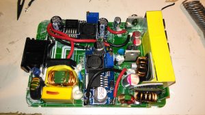
With a squeeze both the boost converter & the buck converter fit into place on the PCB.

Posted on Leave a comment

LG Flatron 22EA53VQ-P Power Issue

I was recently given a pretty nice LED backlit 1080p LG monitor, with the instruction that it wouldn’t power on correctly. The monitor would power on as far as the standby light, but when fully powered on, would flash the backlight momentarily then shut down. A power supply issue was immediately suspected.

LCD Logic Board
LCD Logic Board

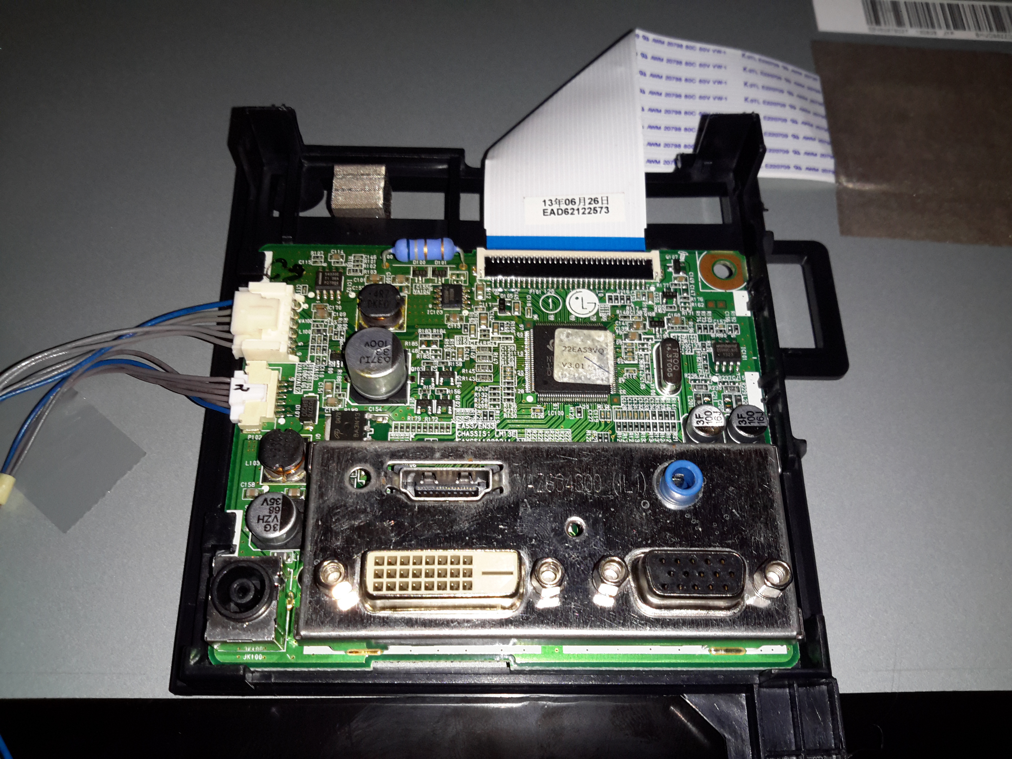
I popped the covers off the monitor itself first, thinking that it was an electrolytic gone bad in the backlight DC-DC converter. Not to mention the fact that cracking into a wall-wart type of PSU is only occasionally possible without the use of anger & large hammers. (Cracking the glue with the handle of a screwdriver doesn’t work so well when the factory went a bit nuts with the glue/ultrasonic welder). As can be seen in the photo, there’s not much inside these monitors, the logic is a single-chip solution, the rest of the PCB is dedicated to supplying the power rails for the various circuits. On the left is the power input & the DC-DC converter for the backlight, along with the DC-DC converter supplying the logic circuits. None of the capacitors here are damaged, everything looks good.
I then measured the output of the PSU, which under no load was the correct 19v DC. However applying any load caused the output voltage to drop like a proverbial brick. Applying a full load of 1.3A saw the output voltage drop so severely that the PSU tripped on it’s UVLO.

200mA Load
200mA Load

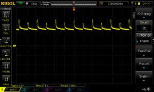
At 200mA of load the factory PSU is already dropping to 18v, with a 5.3kHz switching frequency appearing.

500mA Load
500mA Load

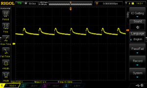
At higher load the frequency increases to 11.5kHz & the output voltage has dropped to 11.86v!

750mA Load
750mA Load

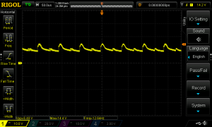
750mA was as high as I could make the supply go without it tripping itself out – the UVLO circuit trips at 9v. 12.6kHz is now riding on the severely low DC at this point.

PSU Ratings
PSU Ratings

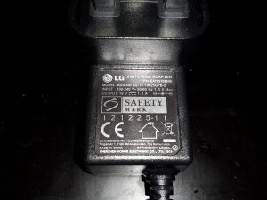
The power supply is supposed to be rated at 1.3A at 19v, however with this fault it’s getting nowhere near that. The LG brand is on this PSU but it’s contracted out to Shenzen Honor Electric Co. Ltd.

Output Electrolytic
Output Electrolytic

Here’s the problem with this PSU. The output electrolytic has ballooned. I don’t have an ESR tester, but this cap has gone way past it’s sell-by date. It’s position right next to the heatsink with the output rectifier diodes has probably cooked it. The PSU isn’t that badly built for a Chinese one – there’s plenty of creepage distance on the PCB & even a couple of isolation slots.

Posted on 2 Comments

CRT Flyback / Line Output Transformer Destructive Teardown

Small Flyback Transformer

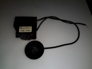
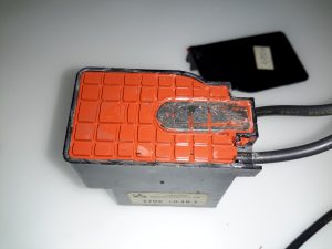
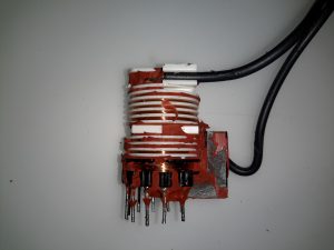
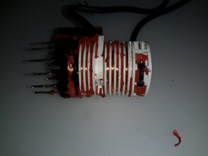
Here’s a small flyback / Line Output Transformer from a portable colour TV set. Usually these transformers are vacuum potted in hard epoxy resin & are impossible to disassemble without anything short of explosives. (There are chemical means of digesting cured epoxies, but none of them are pleasant). This one however, was potted in silicone, so with some digging, the structure of the transformer can be revealed.

Cap Removed
Cap Removed

The cap was glued on to the casing, but this popped off easily. The top of the core is visible in the silicone potting material.

The Digging Starts
The Digging Starts

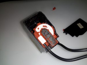
A small screwdriver was used to remove the potting material, while trying not to damage the winding bobbin & core too badly. The bulge in the casing that I originally thought might house a voltage multiplier turns out to be totally empty. The white plastic bobbin is becoming visible around the core.

Bobbin
Bobbin

After some more digging & a lot of mess later, the entire transformer is revealed. The primary & auxiliary secondaries are visible at the bottom of the transformer, next to the pins. These transformers have multiple windings, as they’re used not only for supplying the final anode voltage of several Kilovolts to the CRT, but many of the other associated voltages, for the heater, grids, focus electrodes, etc. These lower voltage windings are on the same part of the core as the primary.
Above those is the main high voltage secondary winding, which looks to be wound with #38-#40AWG wire (about the thinnest available, at 0.07mm diameter. This is wound in many sections of of a few hundred turns each to increase the insulation resistance to the high voltage. The main anode wire emerges from the top of the bobbin.

Output Rectifier
Output Rectifier

Hidden in a recess at the top is the main HV rectifier, which on this small transformer is a single device (it’s probably not internally, most likely a series stack of diodes to get the PIV rating required).

Posted on Leave a comment

Baofeng Battery Capacity Lies

I’ve had a couple of larger batteries for my UV-5Rs for some time now, and decided to do a quick teardown to see if they’re actually the capacity claimed.

BL-5L Battery
BL-5L Battery

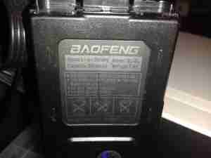
Here’s the label, claiming 3800mAh (3.8Ah) of battery capacity.
These batteries are held together with glue, but a good way to get these kinds of things open is by whacking the seams with the handle of a screwdriver. This cracks the glue without damaging the casing.

Battery Cracked Open

After a few minutes of cracking the seams, the battery comes right open. The pair of wires link the protection board on the cells to the DC terminals on the top of the pack. The charging terminals are under the cardboard insulator on the right.

Cells
Cells

Here’s the other half of the case, with the cells themselves. These are wired in series for a 7.2v pack, and at a capacity of 2600mAh (2.6Ah) printed on them, the label clearly lies about the capacity.

Posted on Leave a comment

The Perfect Companion To The Raspberry Pi

As I’m building a portable “media center” with my first Pi, I was looking for a suitable screen. I remembered the existence of these:

ShowWX+ HDMI Pico Projector

A laser pico projector combined with a Pi, in a small enough package would make a fantastic
little portable media player. So Β£220 was shelled out πŸ™‚

Along with the case for my Pi coming from Mod My Pi, I am aiming for a device as small as possible. At some point I will fit the Pi into the same package as the projector, if it can be cannibalised in such a way πŸ™‚

Check back for an update with running images of the projector, powered from the Pi’s HDMI output.

I will also be doing the standard teardown of the projector when time allows πŸ™‚

Bootnote:
Micro HDMI Connections: These are CRAP. They don’t stand up to any form of day-to-day use, and the projector began displaying a blue screen with “INVALID VIDEO MODE” as soon as anything was plugged into the Micro HDMI port. A quick attack with a jeweller’s screwdriver fixed the port, as it had become loose.

Posted on Leave a comment

Tool-less UK Mains Plug

Plug Bottom
Plug Bottom

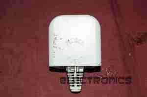
This is a standard 13A UK main power plug – with a twist. This one requires no tools to open or connect.
The top cover is slid off the top, after turning the red cam with a coin to unlock it.

Plug Top
Plug Top

Manufactured by Plugco – a Google search of this company returns no results.

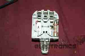
Cover Removed
Cover Removed

Top cover removed from the plug, as is standard with UK mains plugs the live conductor is fused – 3A in this case. The conductors are clamped into the fittings in a row along the top edge of the plug.

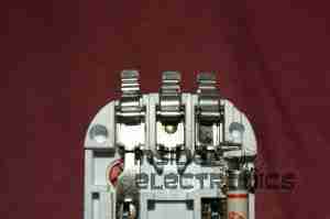
Wire Clamps
Wire Clamps

Closeup of the wire clamps. Conductor is placed in the slot & snapped closed.

This is an old plug & they do not appear to be available these days, for unknown reasons. Being able to change a plug without a screwdriver has it’s advantages πŸ™‚