Time for another random teardown, a signal splitter for HDMI. These units are available very cheap these days on eBay. This one splits the incoming signal into two to drive more than one display from the same signal source.
Main PCB
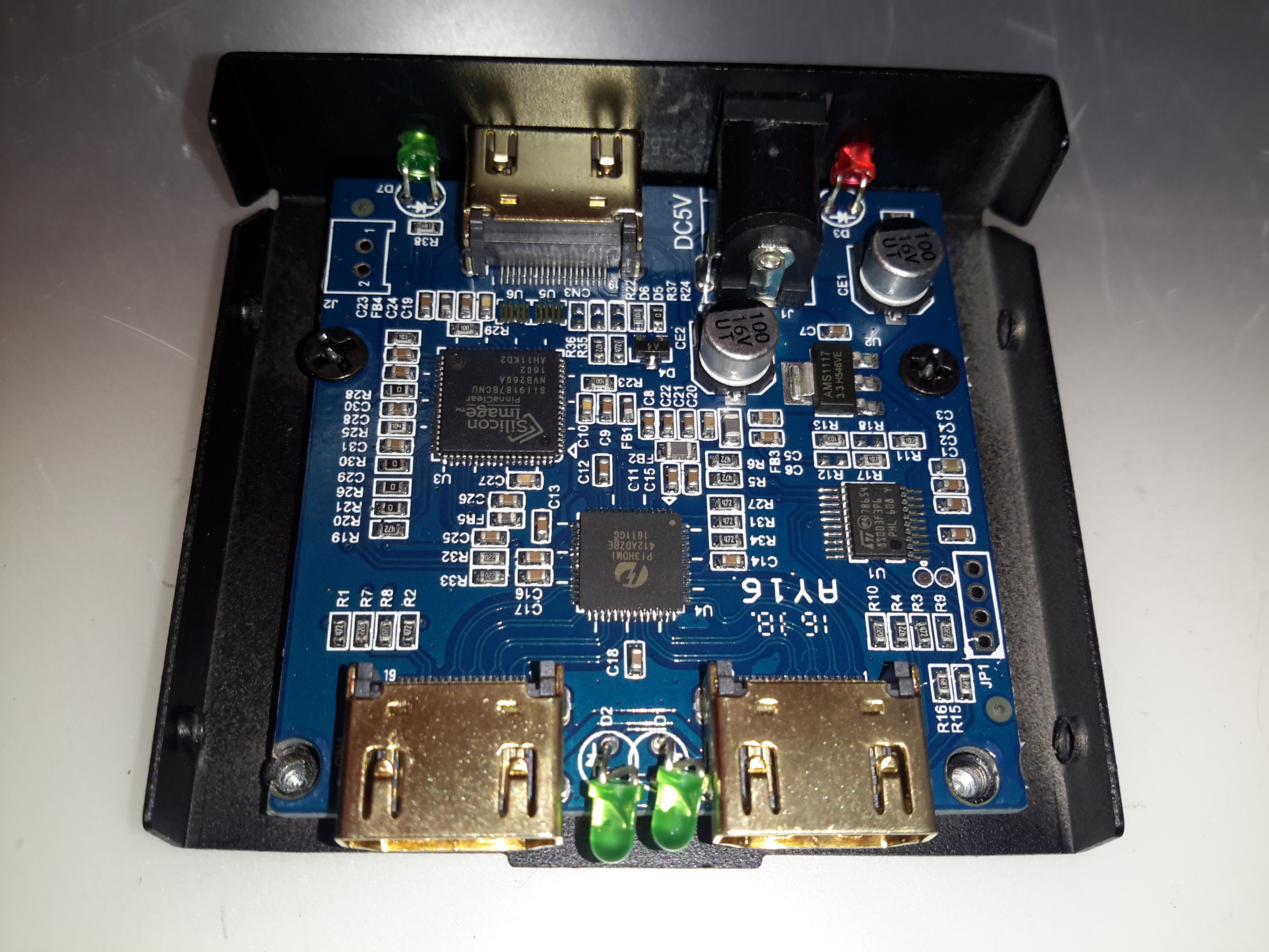
The stamped alloy casing comes apart easily with the removal of a few screws. The PCB inside is rather densely packed with components.
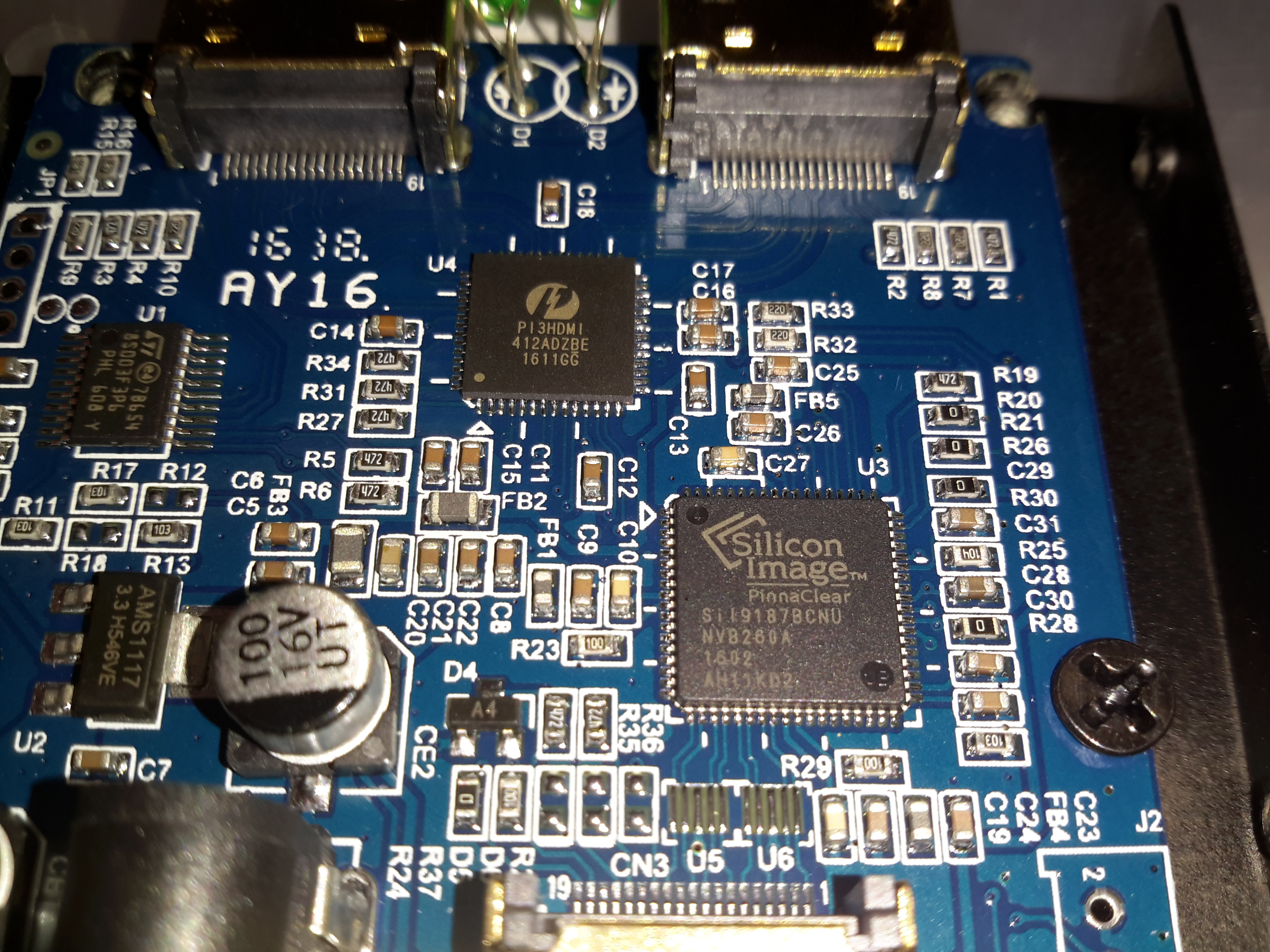
Chipset
The main IC on the incoming signal is a Silicon Image Sil9187B HDMI Port Processor, with a single input & 4 outputs. In this case the chip is used as a repeater to amplify the incoming signal. the signal path then gets fed into a Pericom PI3HDMI412 HDMI Demux, which then splits the signal into two for the output ports.
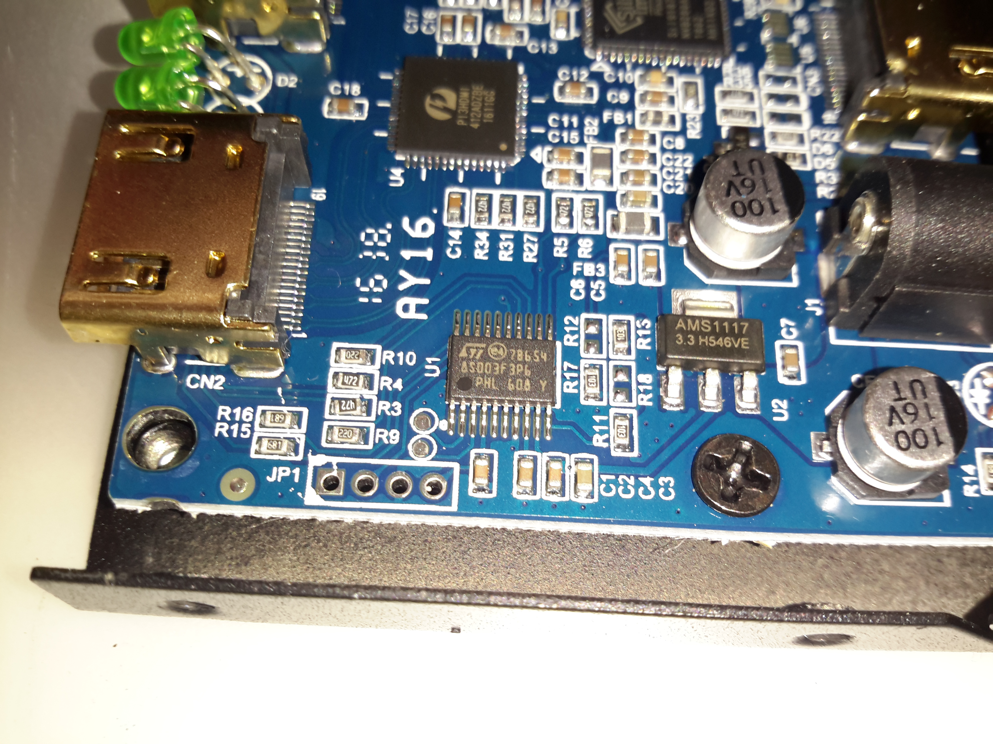
Microcontroller
The main pair of ICs processing the video signals are controlled over I²C, with this STM32 microcontroller. The 4 pads to the lower left are for the STLink programmer. The main 3.3v power rail is provided by the LM1117 linear regulator on the right.
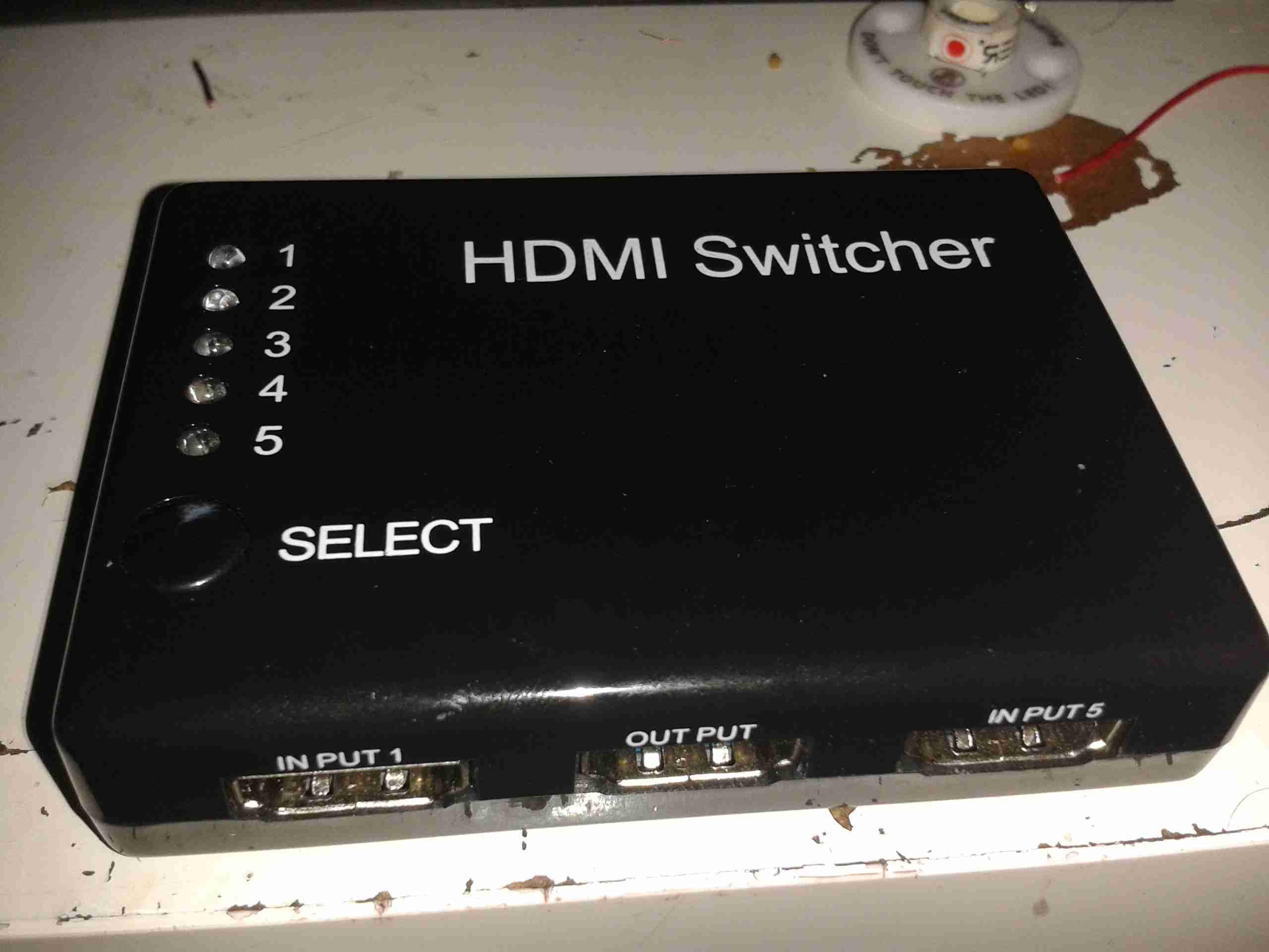
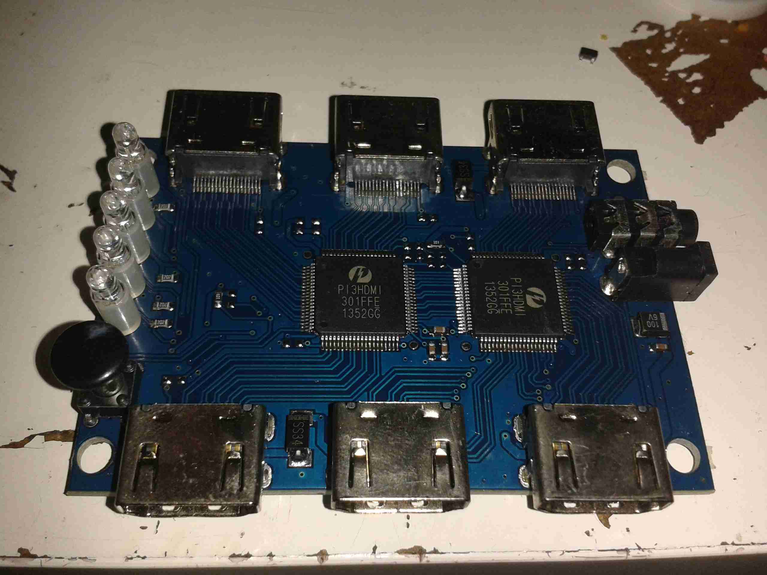
Here’s another quick teardown, a cheap 5-port HDMI switch box. This is used to allow a single input on a monitor to be used by 5 different external HDMI devices, without having to mess about plugging things in.
Power & Remote
Here’s the DC barrel jack & 3.5mm TRS jack for power & remote control. There’s a little IR decoder & remote that go with this for hands free switching.
PCB Top
Here’s the PCB out of it’s plastic housing. The main logic is a pair of PI3HDMI303 3:1 HDMI switches from Pericom Semiconductor. These are cascaded for the 5-ports, the first 3 input HDMI ports are switched through both ICs to reach the output.
These HDMI switch ICs are operated with TTL input pins, the combination of these pins held either high or low determines the input port that appears on the output.
There’s a button on the left for switching between inputs, with a row of 5 LED indicators.
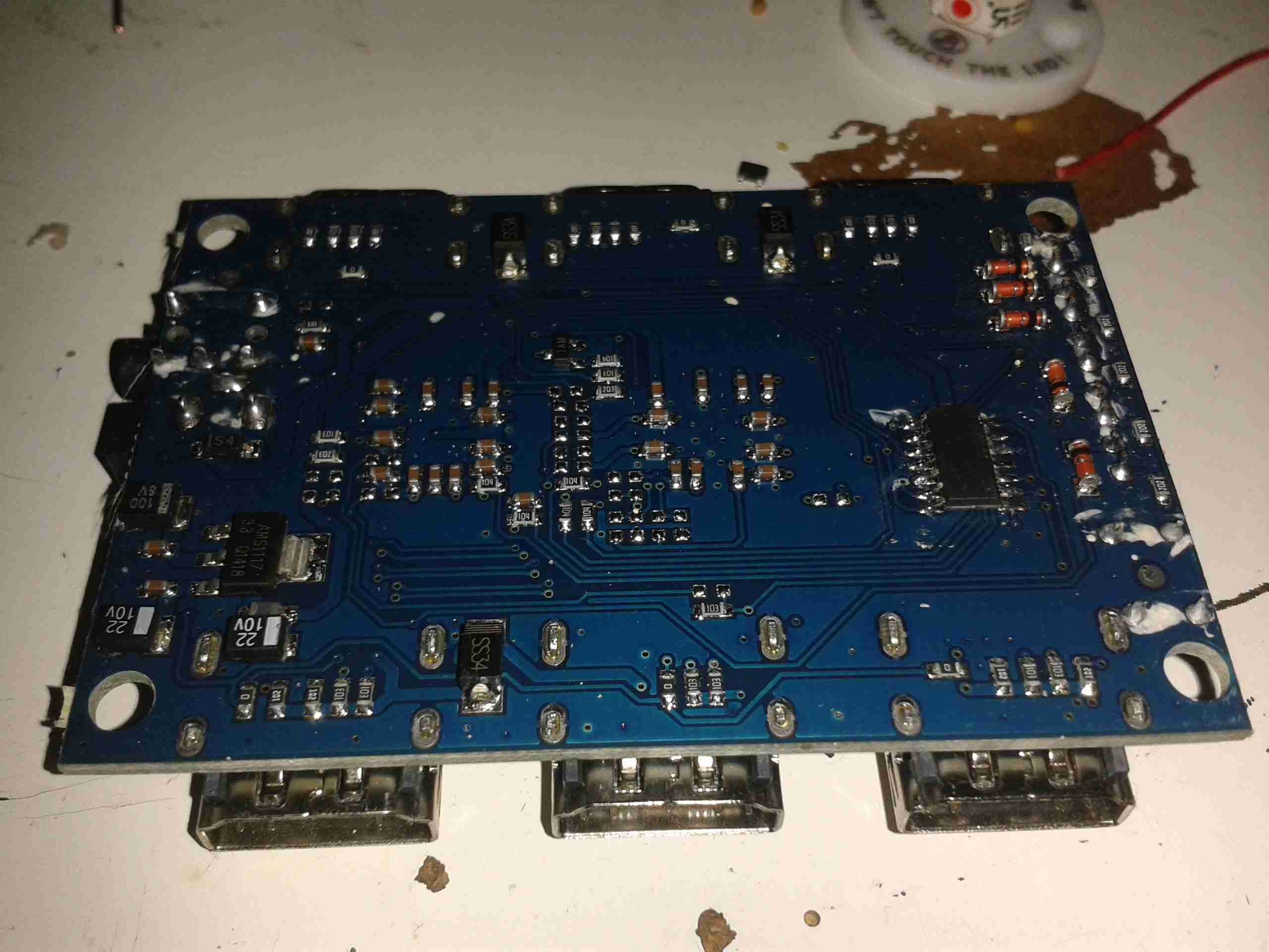
PCB Bottom
Not much on the bottom side, a lot of passives & bypass capacitors. There’s a 3.3v LDO regulator on the left for supplying the main rail to the active switch ICs. The IC on the right doesn’t have any numbering at all, but I’m presuming it’s a microcontroller, dealing with the IR remote input & pushbutton inputs to switch the inputs.
This will be the record of building a new Media PC, above you can see the finished system.
It’s Mini-ITX based, with on-board HDMI output, specifically to run XBMC via Fedora for media purposes.
CiC MTX001B Mini-ITX Case
This is the case that is being used, around the size of a Shuttle PC. It has a single 3.5″ & 5 1/4″ bay, for a HDD & ODD, front panel USB, Firewire & Audio.
Intel BLKDH57JG Mini-ITX Motherboard
Motherboard to fit the case. Supports Intel Core i5 series CPUs, with up to 8GB of DDR3 RAM.
Other features are on-board full surround audio, HDMI, eSATA, & a single 16x PCIe slot.
Corsair 4GB DDR3 DIMMs
Matching memory for the motherboard, a pair of 4GB DDR3 units.
Akasa K25 Low Profile CPU Cooler
Having never been impressed by bundled coolers with CPUs, here is an aftermarket low-profile unit, with solid copper core for enhanced cooling. This cooler is specially designed for Mini-ITX uses.
Intel Core i5 650 Dual Core 3.2GHz CPU
The brains of the operation, Core i5 650 CPU, should handle HD video well.
This is a little script to make OMXPlayer on the Raspberry Pi cycle through every file in a specified folder, useful for playing sequential movies or series of episodes.
#!/bin/bash
if [ x"$1" = x"help" -o x"$1" = x"--help" -o x"$1" = x"-help" ];then
echo "Usage: omxseries [folder path]"
echo "Audio Mode can be either 'hdmi' or 'local'."
echo "Folder Path is the full path to the video files on your system."
echo "This script will attempt to play every file in the target folder, with any file extension,"
echo "so ensure that only valid video files are present in the target folder to avoid errors."
exit
fi
for file in $2/*
do
 omxplayer -o $1 $file
done
Example:
[root@raspbian ~]# omxseries hdmi /media/stuff/videos
would play everything in /media/stuff/videos and send the audio over the HDMI port.
Here’s the teardown of the projector itself! On the right is the info label from the projector, which covers the flex ribbon to the VGA/composite input board below.
This unit is held together with Allen screws, but is easy to get apart.
PicoP Display Engine
Here’s the insides of the projector, with just the top cover removed. The main board can be seen under the shielding can, the Micro HDMI connector is on the left & the MicroUSB connection is on the right. The USB connection is solely for charging the battery & provides no data interface to the unit.
On top of the main board is the shield can covering the PicoP Display Engine driver board, this shield was soldered on so no peek inside unfortunately!
Laser Module
The laser module itself is in the front of the unit, the laser assemblies are closest to the camera, on the left is the Direct Doubled Green module, in the centre is the blue diode, and the red diode on the right. Inside the module itself is an arrangement of mirrors & beamsplitters, used to combine the RGB beams from the lasers into a single beam to create any colour in the spectrum.
Module Innards
Here is the module innards revealed, the laser mounts are at the top of the screen, the green module is still mounted on the base casting.
The three dichroic mirrors in the frame do the beam combining, which is then bounced onto the mirror on the far left of the frame, down below the MEMs. From there a final mirror directs the light onto the MEMs scanning mirror before it leaves through the output window.
A trio of photodiodes caters for beam brightness control & colour control, these are located behind the last dichroic turning mirror in the centre of the picture.
Green Module Cavity
This is inside the green laser module, showing the complexity of the device. This laser module is about the size of a UK 5p coin!
Green Module Labeled
And here on the left is the module components labelled.
Main PCB Top
Here is the main PCB, with the unit’s main ARM CPU on the right, manufactured by ST.
User buttons are along the sides.
Main PCB Bottom
Other side of the main board, with ICs that handle video input from the HDMI connector, battery charging via the USB port & various other management.
Above is the image projected from the Pi, on the default login screen. Distance from the projector is approx 10 feet.
Projector
State of the art projector mount, fashioned from several cable ties. HDMI cable is plugged into the right hand side of the projector.
Unfortunately the projector cannot handle audio on the HDMI connector, the 3.5mm headphone jack on the projector is for splitting audio out of the iDevice connection only, and does not make the HDMI audio stream available.
Pi
The Raspberry Pi, hosting a USB keyboard, & USB powered speakers. Running the standard Debian release, on a 16GB card, with omxplayer installed for media functions.
As I’m building a portable “media center” with my first Pi, I was looking for a suitable screen. I remembered the existence of these:
ShowWX+ HDMI Pico Projector
A laser pico projector combined with a Pi, in a small enough package would make a fantastic
little portable media player. So £220 was shelled out 🙂
Along with the case for my Pi coming from Mod My Pi, I am aiming for a device as small as possible. At some point I will fit the Pi into the same package as the projector, if it can be cannibalised in such a way 🙂
Check back for an update with running images of the projector, powered from the Pi’s HDMI output.
I will also be doing the standard teardown of the projector when time allows 🙂
Bootnote:
Micro HDMI Connections: These are CRAP. They don’t stand up to any form of day-to-day use, and the projector began displaying a blue screen with “INVALID VIDEO MODE” as soon as anything was plugged into the Micro HDMI port. A quick attack with a jeweller’s screwdriver fixed the port, as it had become loose.
Well I got my delivery info finally, the week commencing 28/05/2012. Experiments to come once I have it!
Tip Jar
If you’ve found my content useful, please consider leaving a donation by clicking the Tip Jar below!
All collected funds go towards new content & the costs of keeping the server online.