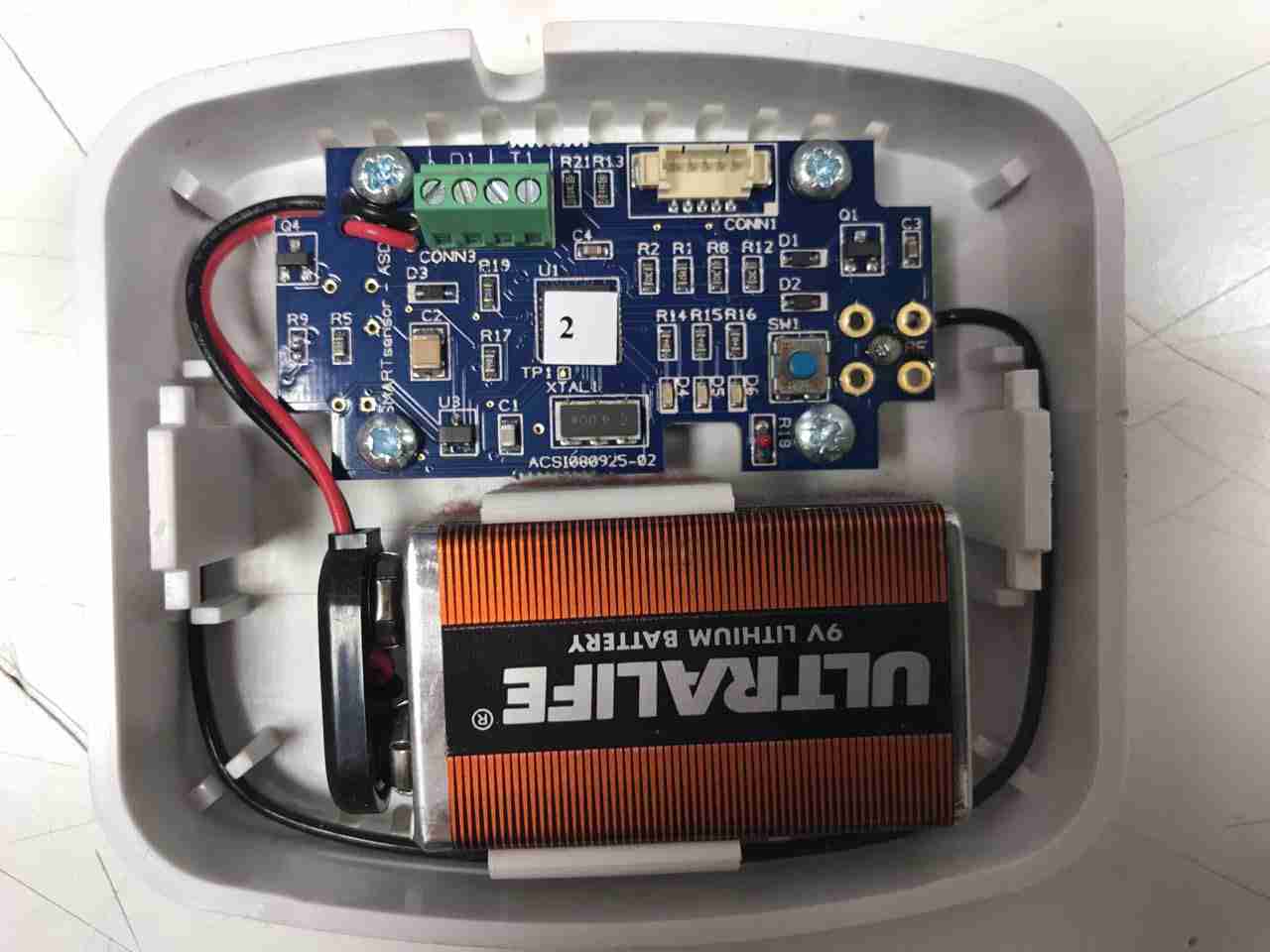
Here’s another random bit of RF tech, I’m told this is a wireless energy management sensor, however I wasn’t able to find anything similar on the interwebs. It’s powered by a standard 9v PP3 battery.
Microcontroller
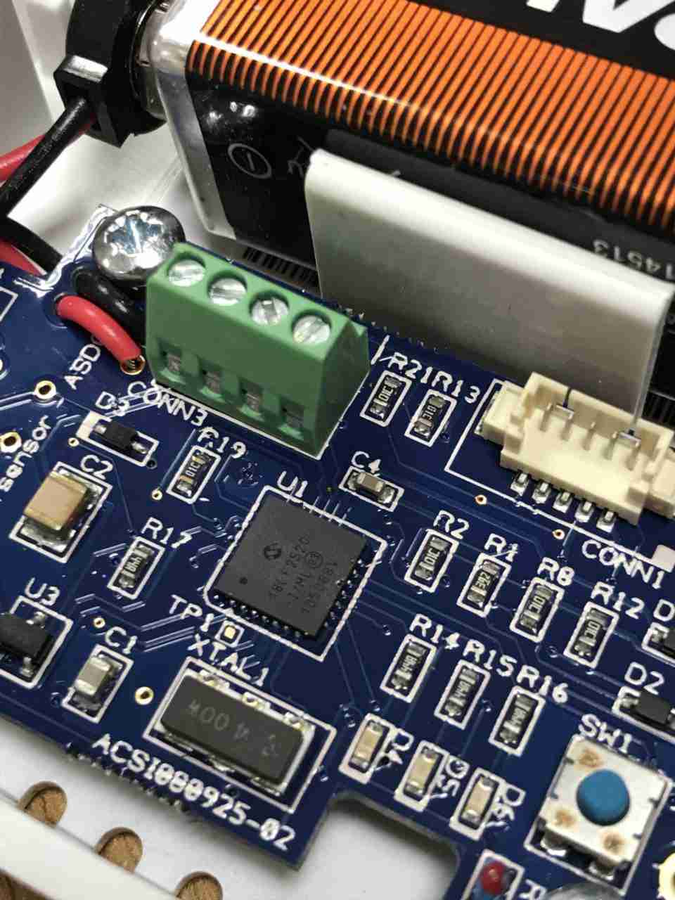
System control is handled by this Microchip PIC18F2520 Enhanced Flash microcontroller, this has an onboard 10-bit ADC & nanoWatt technology according to their datasheet. There’s a 4MHz crystal providing the clock, with a small SOT-23 voltage regulator in the bottom corner. There’s a screw terminal header & a plug header, but I’ve no idea what these would be used for. Maybe connecting an external voltage/current sensor & a programming header? The tactile button I imagine is for pairing the unit with it’s controller.
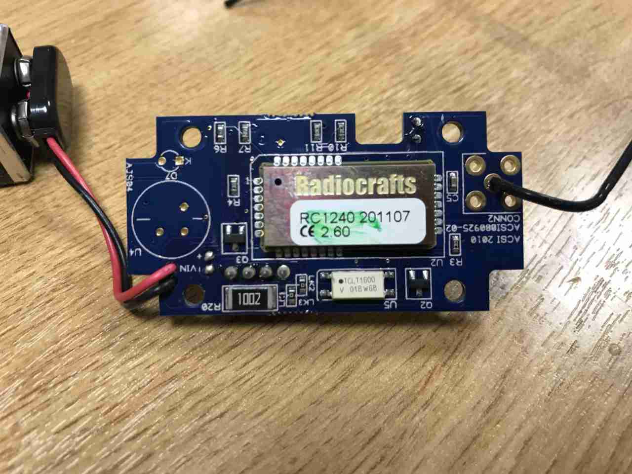
PCB Bottom
The bottom of the PCB is almost entirely taken up by a Radiocrafts RC1240 433MHz RF transceiver. Underneath there’s a large 10kΩ resistor, maybe a current transformer load resistor, and a TCLT1600 optocoupler. Just from the opto it’s clear this unit is intended to interface in some way to the mains grid. The antenna is connected at top right, in a footprint for a SMA connector, but this isn’t fitted.
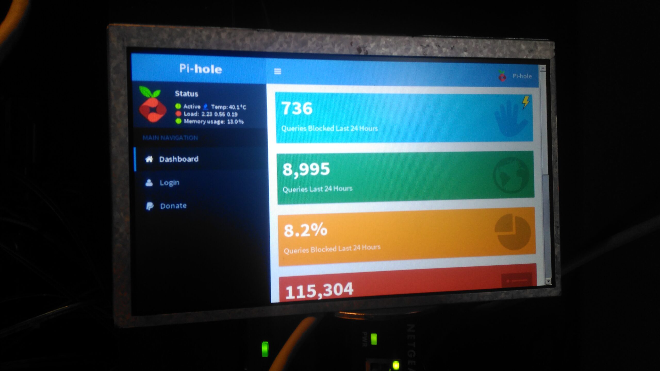
On my home network I have a system running PiHole – a DNS server that blocks all unwanted traffic, such as ads. Since I have an official Pi LCD with a broken touch panel, I decided to use the bare LCD as a status display for PiHole.
This requires some extra packages installing onto the base system after PiHole is installed & configured, and the interface automatically starts on bootup. I used the latest Raspbian Jessie Minimal image for this system, and ran everything over a SSH connection.
First thing, get the required packages installed onto the Pi:
Once these are installed, it’s time to configure the startup script for Midori to display the status page. Create StartMidori.sh in /home/pi and fill with the following:
#!/bin/sh export DISPLAY=:0
xset -dpms
xset s off
xset s noblank
unclutter &
matchbox-window-manager &
midori -e Fullscreen -a http://127.0.0.1/admin/
This script disables all power management on the system to keep the LCD on, starts unclutter to hide the mouse pointer and finally starts the Matchbox Window Manager to run Midori, which itself is set to fullscreen mode, and the URL of the admin panel is provided.
The next step is to test, give the script executable permissions, and run the script:
Once this is run, the LCD should come to life after a short delay with the PiHole stats screen. Close the test & return to the terminal by hitting CTRL+C.
Now the Pi can be configured to autorun this script on boot, the first thing to do here is to enable autologin on the console. This can be done with raspi-config, select Option 3 (Boot Options), then Option B1 (Desktop/CLI), then Option B2 (Console Autologin). When prompted to reboot, select No, as we’ll be finishing off the config before we reboot the system.
The next file to edit is /etc/rc.local, add the command to start the status browser up:
#!/bin/sh -e
#
# rc.local
#
# This script is executed at the end of each multiuser runlevel.
# Make sure that the script will "exit 0" on success or any other
# value on error.
#
# In order to enable or disable this script just change the execution
# bits.
#
# By default this script does nothing.

# Print the IP address
_IP=$(hostname -I) || true
if [ "$_IP" ]; then
  printf "My IP address is %s\n" "$_IP"
fi
sudo xinit /home/pi/StartMidori.sh &
exit 0
Here I’ve added in the command just above “exit 0”. This will start the browser as the last thing on bootup. The Pi can now be rebooted, and the status display should start on boot!
This was originally going to be part of another post, but it ended up getting more complex than I originally intended so it’s been given it’s own. I go into into many of my personal security practices, on both my public facing servers & personal machines. Since the intertubes are so central to life these days, good security is a must, especially since most people use the ‘net to do very sensitive operations, such as banking, it’s becoming even more essential to have strong security.
Since bringing the new server online & exposing it to the world, it’s been discovered in record time by the scum of the internet, SSH was under constant attack within 24 hours, and within that time there were over 20,000 failed login attempts in the logs.
This isn’t much of an issue, as I’ve got a strong Fail2Ban configuration running which at the moment is keeping track of some 30 IP addresses that are constantly trying to hammer their way in. No doubt these will be replaced with another string of attacks once they realise that those IPs are being dropped. I also prevent SSH login with passwords – RSA keys only here.
MySQL is the other main target to be concerned about – this is taken care of by disabling root login remotely, and dropping all MySQL traffic at the firewall that hasn’t come from 127.0.0.1.
Keeping the SSH keys on an external device & still keeping things simple just requires some tweaking to the .bashrc file in Linux:
alias ssh='ssh -i <Path To Keys>'
This little snippet makes the ssh client look somewhere else for the keys themselves, while keeping typing to a minimum in the Terminal. This assumes the external storage with the keys always mounts to the same location.
Everything else that can’t be totally blocked from outside access (IMAP, SMTP, FTP, etc), along with Fail2Ban protection, gets very strong passwords, unique to each account, (password reuse in any situation is a big no-no) and where possible TOTP-based two factor authentication is used for front end stuff, all the SSH keys, master passwords & backup codes are themselves kept offline, on encrypted storage, except for when they’re needed. General password management is taken care of by LastPass, and while they’ve been subject to a couple of rather seriousvulnerabilities recently, these have been patched & it’s still probably one of the best options out there for a password vault.
There’s more information about those vulnerabilities on the LastPass blog here & here.
This level of security paranoia ensures that unauthorized access is made extremely difficult – an attacker would have to gain physical access to one of my mobile devices with the TOTP application, and have physical access to the storage where all the master keys are kept (along with it’s encryption key, which is safely stored in Meatware), to gain access to anything.
No security can ever be 100% perfect, there’s always going to be an attack surface somewhere, but I’ll certainly go as far as is reasonable, while not making my access a total pain, to keep that attack surface as small as possible,and therefore keeping the internet scum out of my systems.
The last layer of security is a personal VPN server, which keeps all traffic totally encrypted while it’s in transit across my ISP’s network, until it hits the end point server somewhere else in the world. Again, this isn’t perfect, as the data has to be decrypted *somewhere* along the chain.
I’ve been running my own VPN so I can access my home-based servers from anywhere with an internet connection (not to mention, in this day & age of Government snooping – personal privacy & increased security).
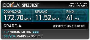
I’m on a pretty quick connection from Virgin Media here in the UK, currently the fastest they offer:
Virgin Media
To do these tests, I used the closest test server to my VPN host machine, in this case Paris. This keeps the variables to a minimum. Testing without the VPN connection gave me this:
Paris Server Speed
I did expect a lower general speed to a server further away, this will have much to do with my ISP’s traffic management, network congestion, etc. So I now have a baseline to test my VPN throughput against.
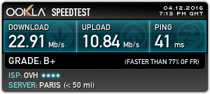
The problem I’ve noticed with OpenVPN stock configs are that the connections are painfully slow – running over UDP on the usual port of 1194 the throughput was pretty pathetic:
Stock Config Speed
I did some reading on the subject, the first possible solution being to change the send/receive buffers so they’re set to a specific value, rather than letting the system handle them. I also added options to get the server to push these values to the clients, this saving me the trouble of having to reissue all the client configurations.
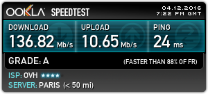
Unfortunately just this option didn’t work as well as I’d like, downstream speeds jumped to 25Mb/s. In the stock config, the tunnel MTU & MSSFIX settings aren’t bothered with, some adjustment to set the tunnel MTU to lower than the host link MTU (in my case the standard 1500) prevents packet fragmentation, MSSFIX let’s the client TCP sessions know to limit the packet sizes it sends so that after OpenVPN has done the encryption & encapsulation, the packets do not exceed the set size. This also helps prevent packet fragmentation.
tun-mtu 1400
mssfix 1360
VPN Tweaked
After adjusting these settings, the download throughput over the VPN link has shot up to 136Mb/s. Upload throughput hasn’t changed as this is limited by my connection to Virgin Media. Some more tweaking is no doubt possible to increase speeds even further, but this is fine for me at the moment.
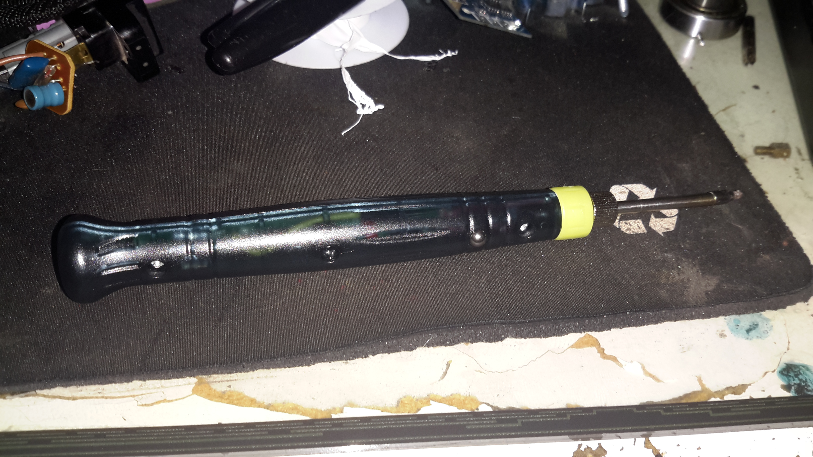
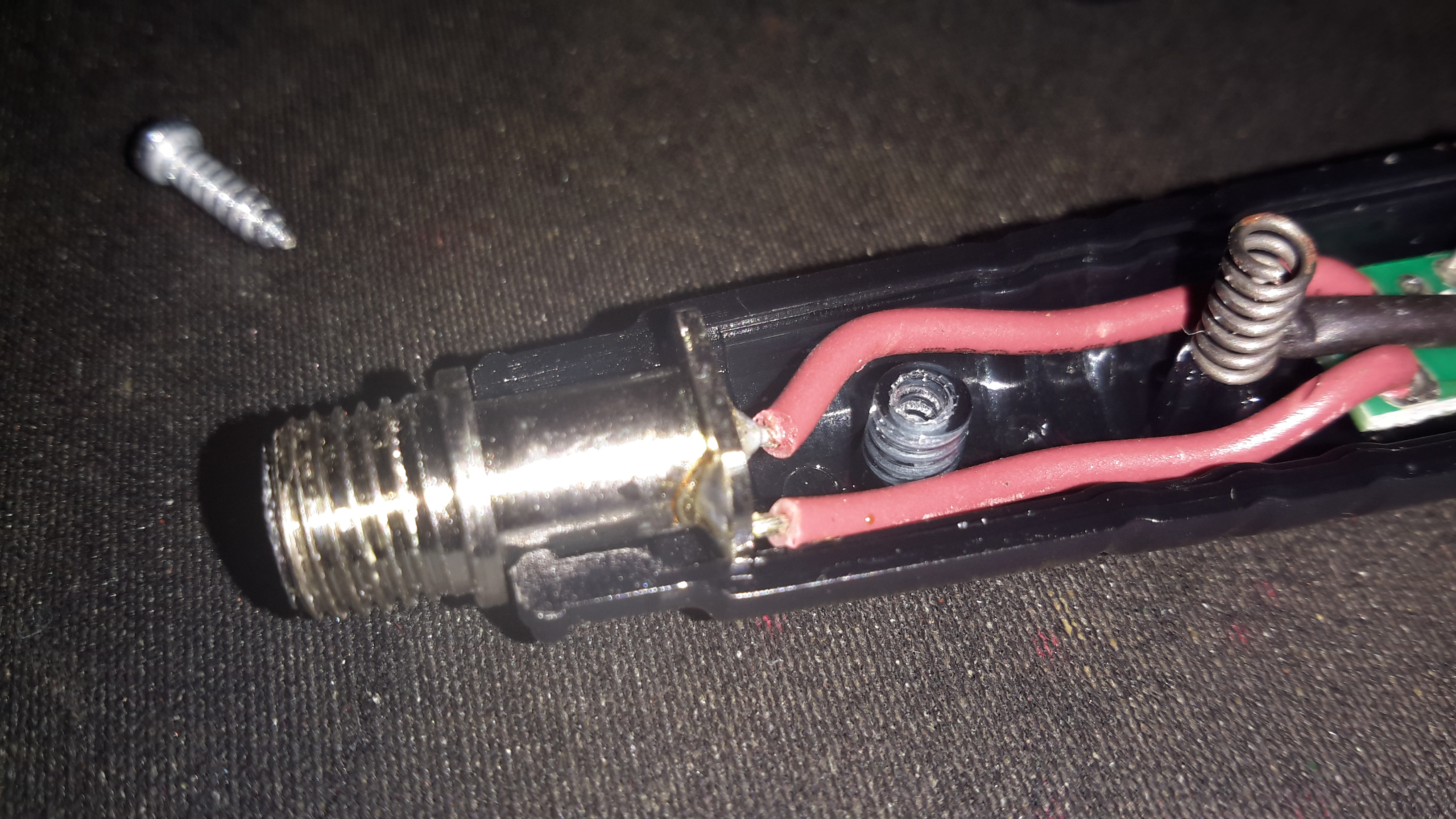
Here’s a novel little gadget, a USB powered soldering iron. The heating tip on these is very small & might be useful for very small SMD work. Bigger joints not so much, as it’s only rated at 8W. (Still breaks the USB standard of 2.5W from a single port).
These irons aren’t actually too bad to use, as long as the limitations in power are respected. Since nearly everything has a USB power port these days, it could make for a handy emergency soldering iron.
Heater Socket
The heater & soldering bit are a single unit, not designed to be replaced separately. (I’ve not managed to find replacement elements, but at £3 for the entire iron, it would be pretty pointless).
Above is the socket where the heater plugs in, safely isolating the plastic body from any stray heat.
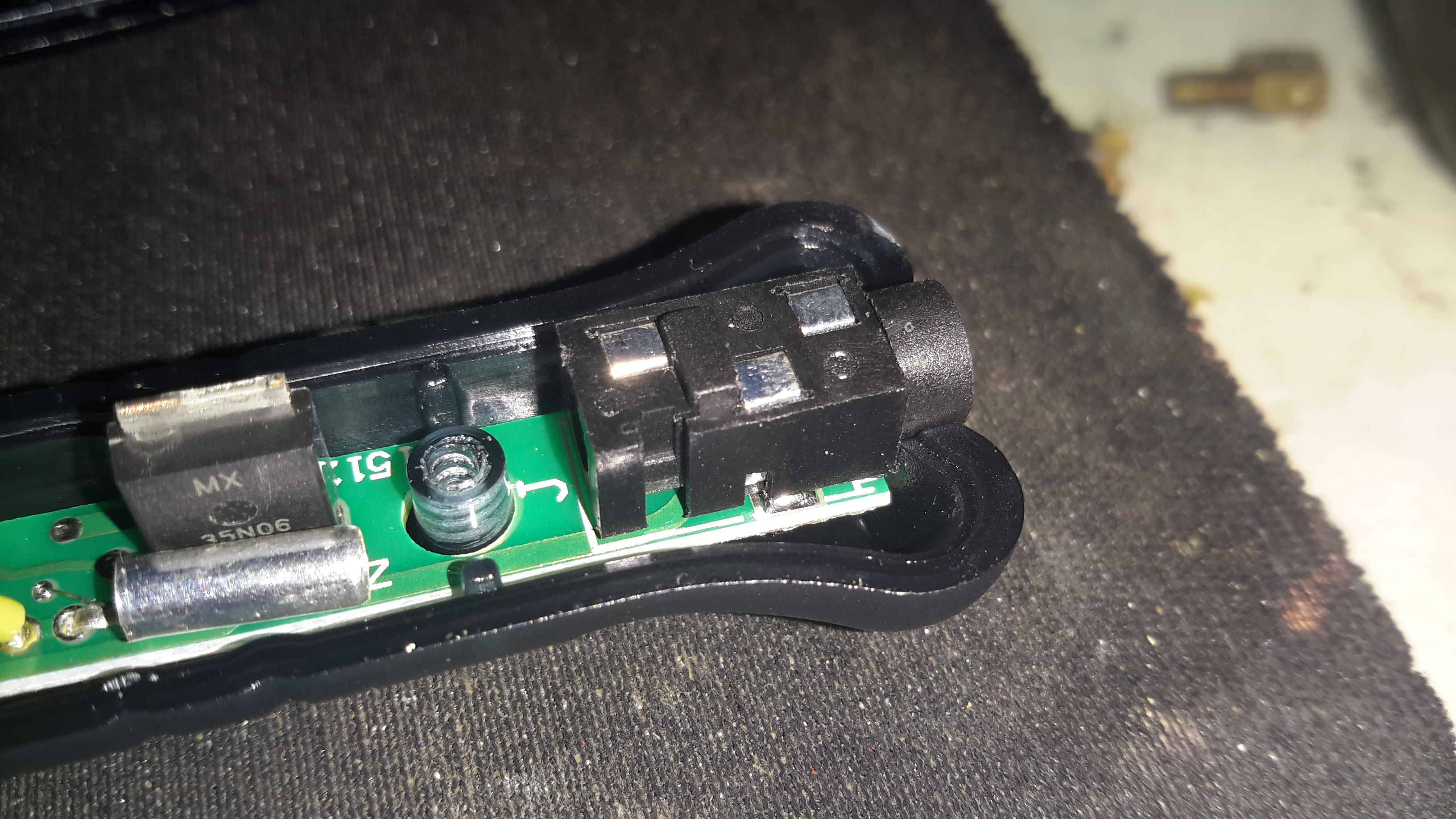
DC Input Jack
The DC input is a 3.5mm audio jack, a non-standard USB to 3.5mm jack cable is supplied. Such non-standard cables have the potential to damage equipment that isn’t expecting to see 5v on an audio input if it’s used incorrectly.
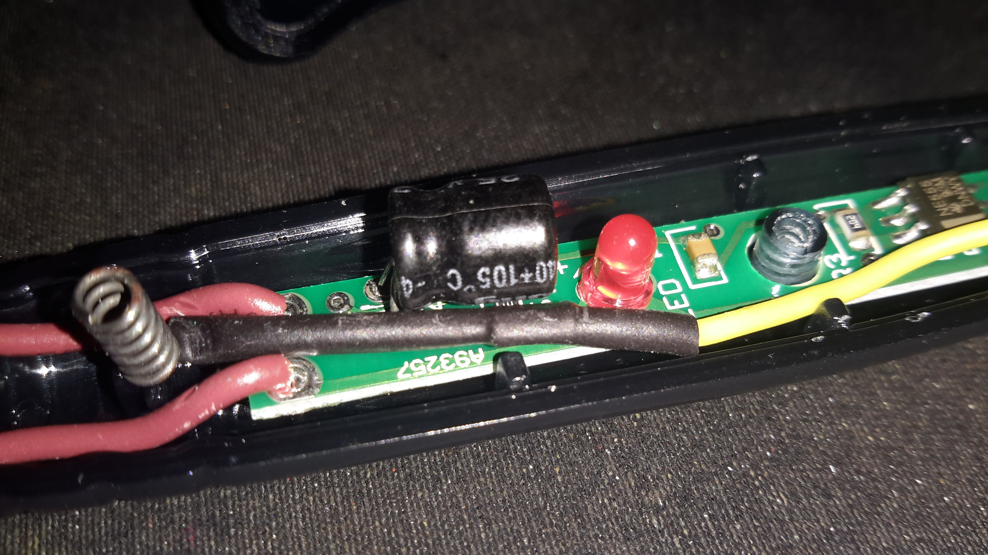
Touch Sensor & LED
There isn’t actually a switch on this unit for power management, but a clever arrangement of a touch button & vibration switch. The vertical spring in the photo above makes contact with a steel ball bearing pressed into the plastic housing, forming the touch contact.
MOSFET
The large MOSFET here is switching the main heater current, the silver cylinder in front is the vibration switch, connected in parallel with the touch button.
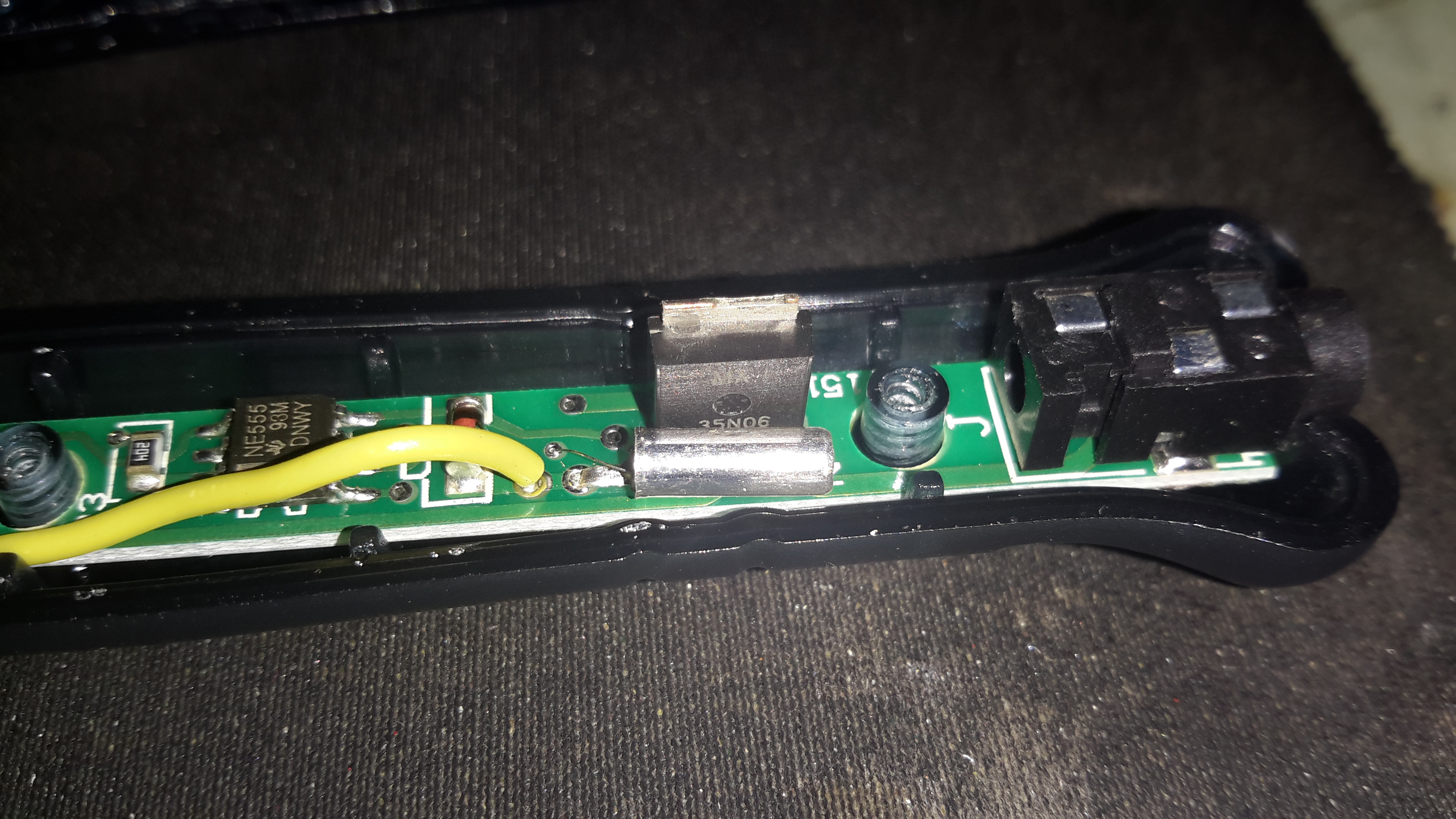
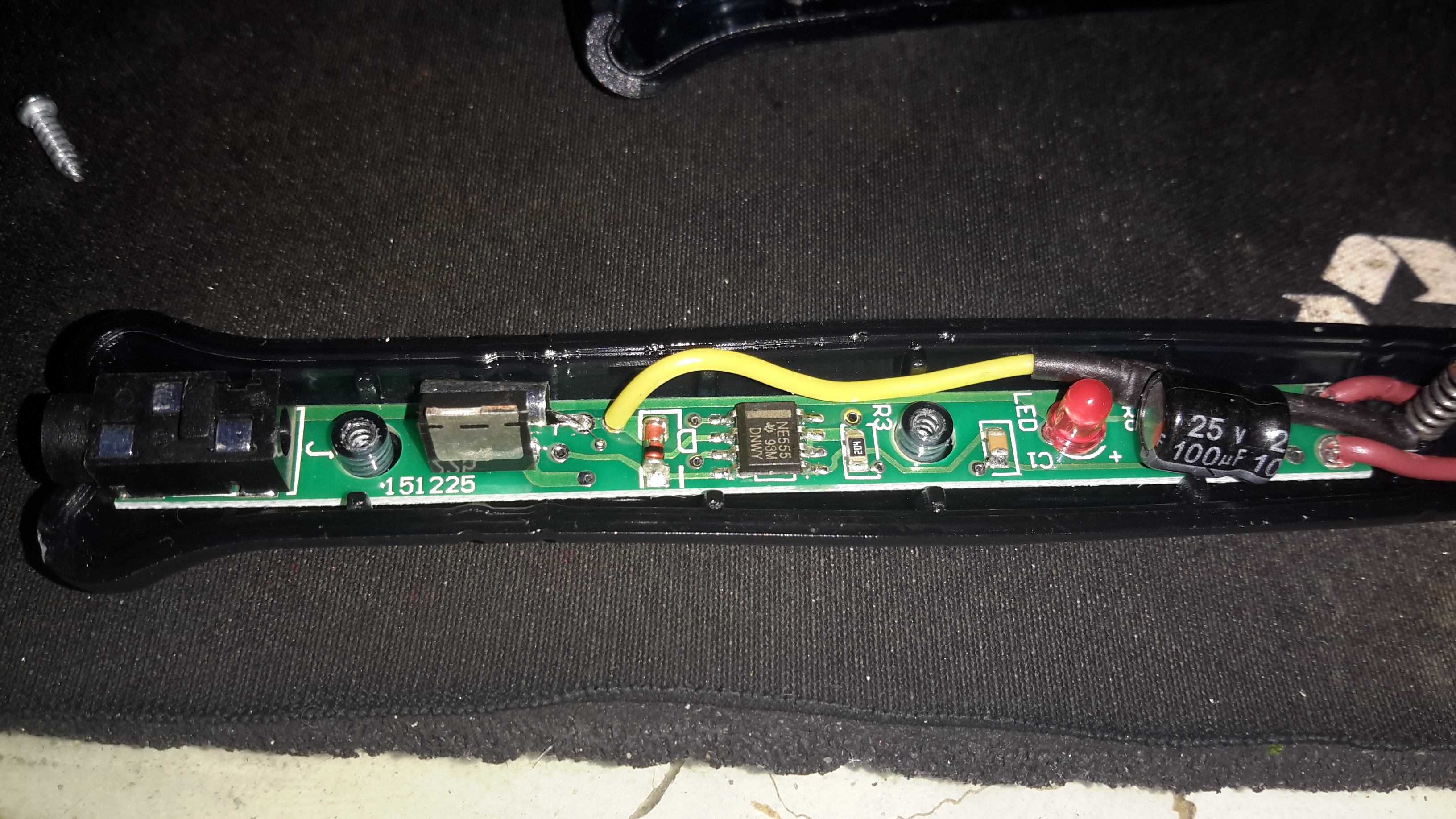
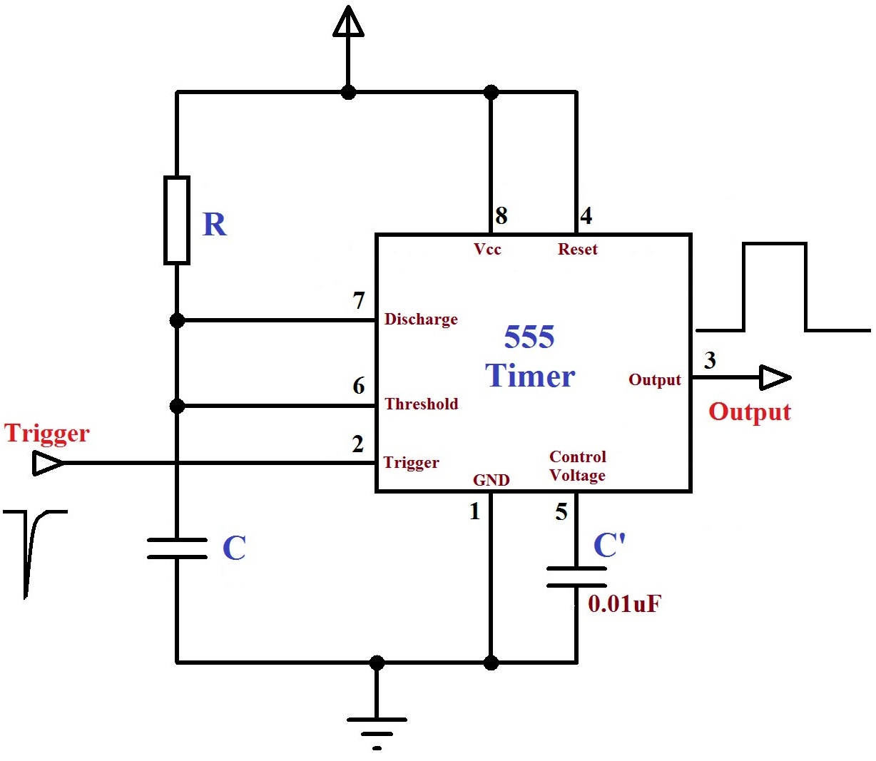
PCB
The main controller is very simple. It’s a 555 timer configured in monostable mode. Below is a schematic showing the basic circuit.
555 Monostable
Big Clive also did a teardown & review of this iron. Head over to YouTube to watch.
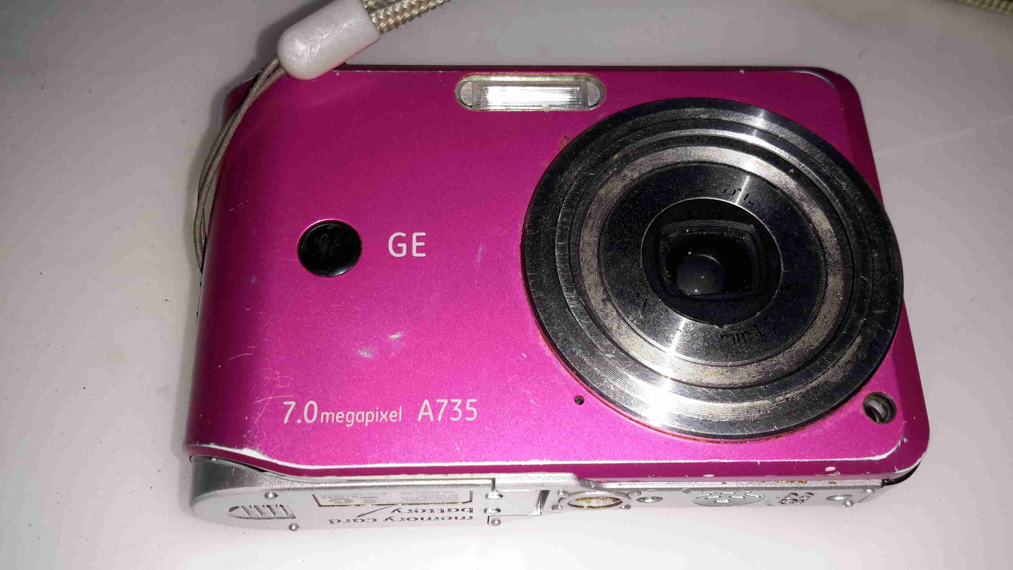
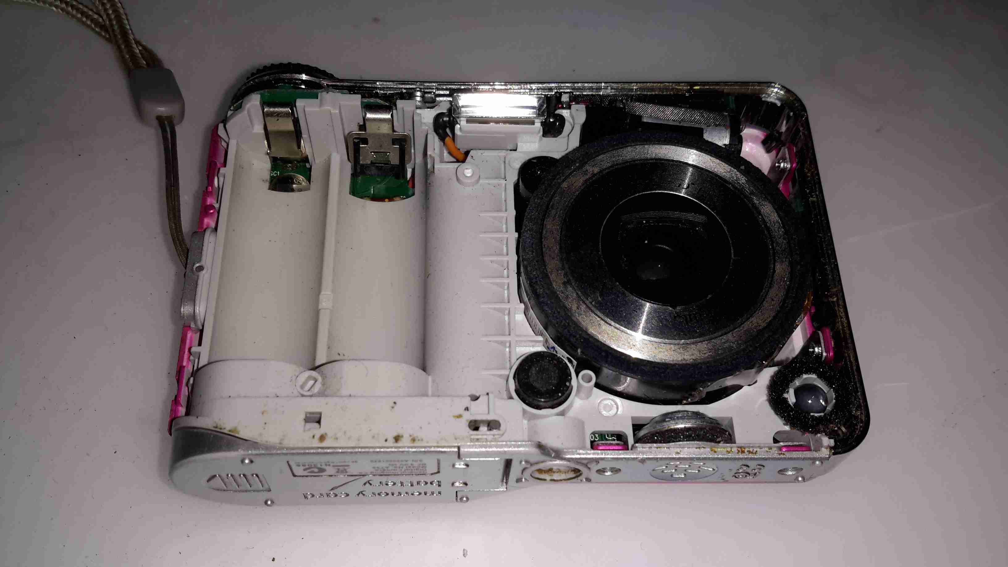
This camera has now been retired after many years of heavy use. Exposure to a 3-year old has caused severe damage to the lens mechanism, which no longer functions correctly.
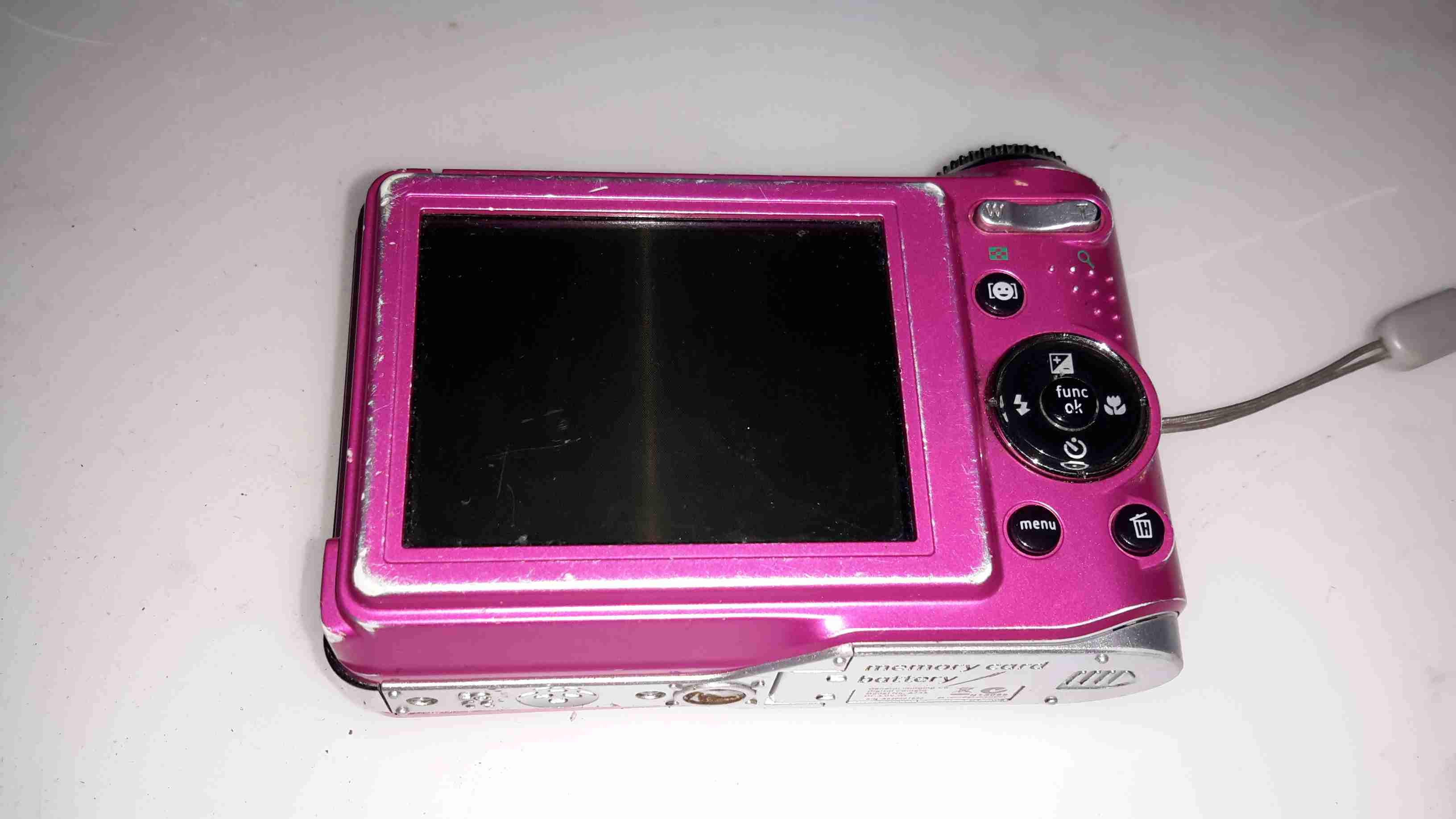
Rear Panel
Pretty much standard interface for a digital camera, with a nice large LCD for it’s time.
Front Cover Removed
With the front cover removed, the lens assembly & battery compartment is exposed.
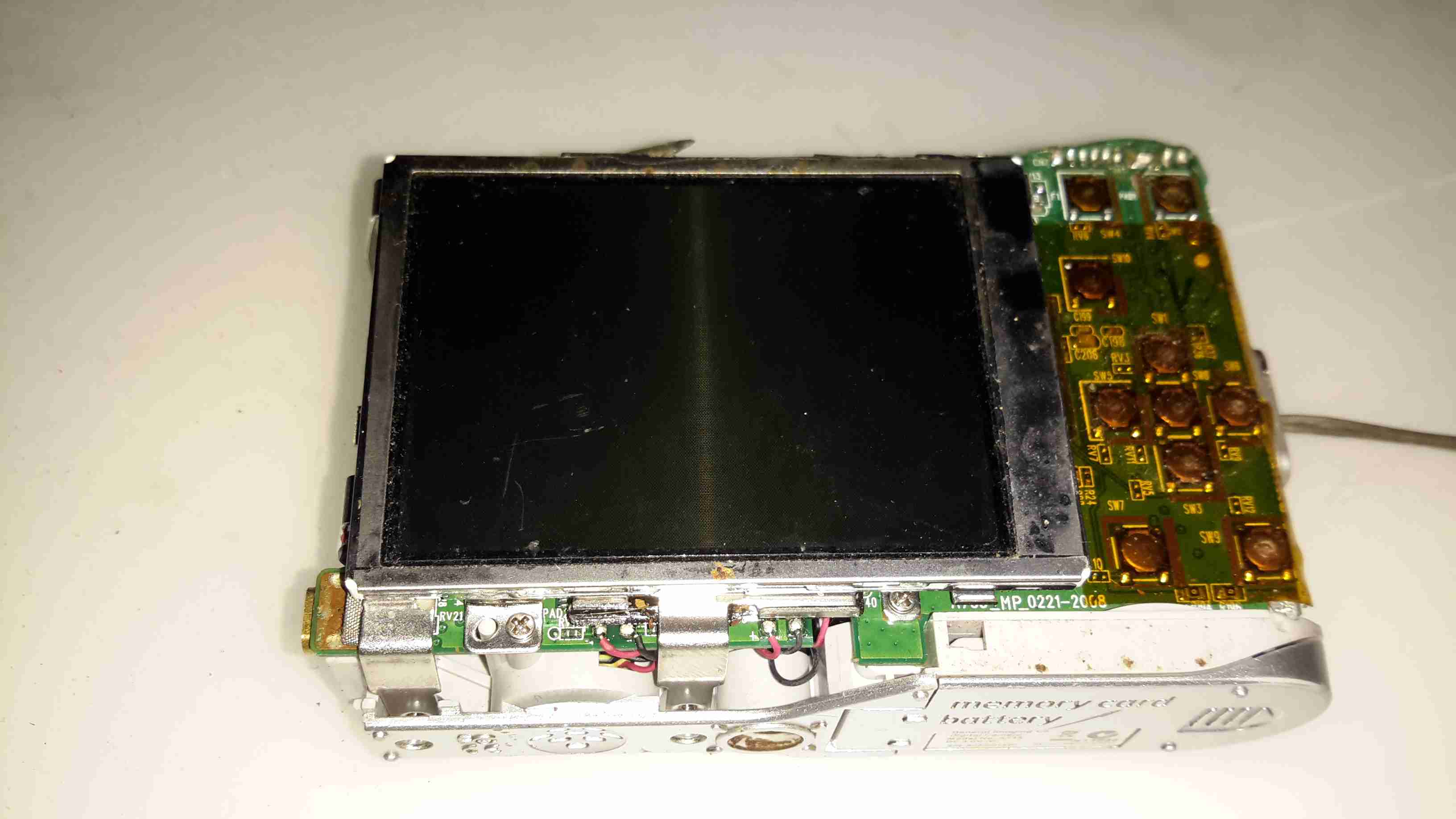
Rear Cover Removed
Removing the rear cover exposes the LCD module & the main PCB, the interface tactile switches are on the right under a protective layer of Kapton tape.
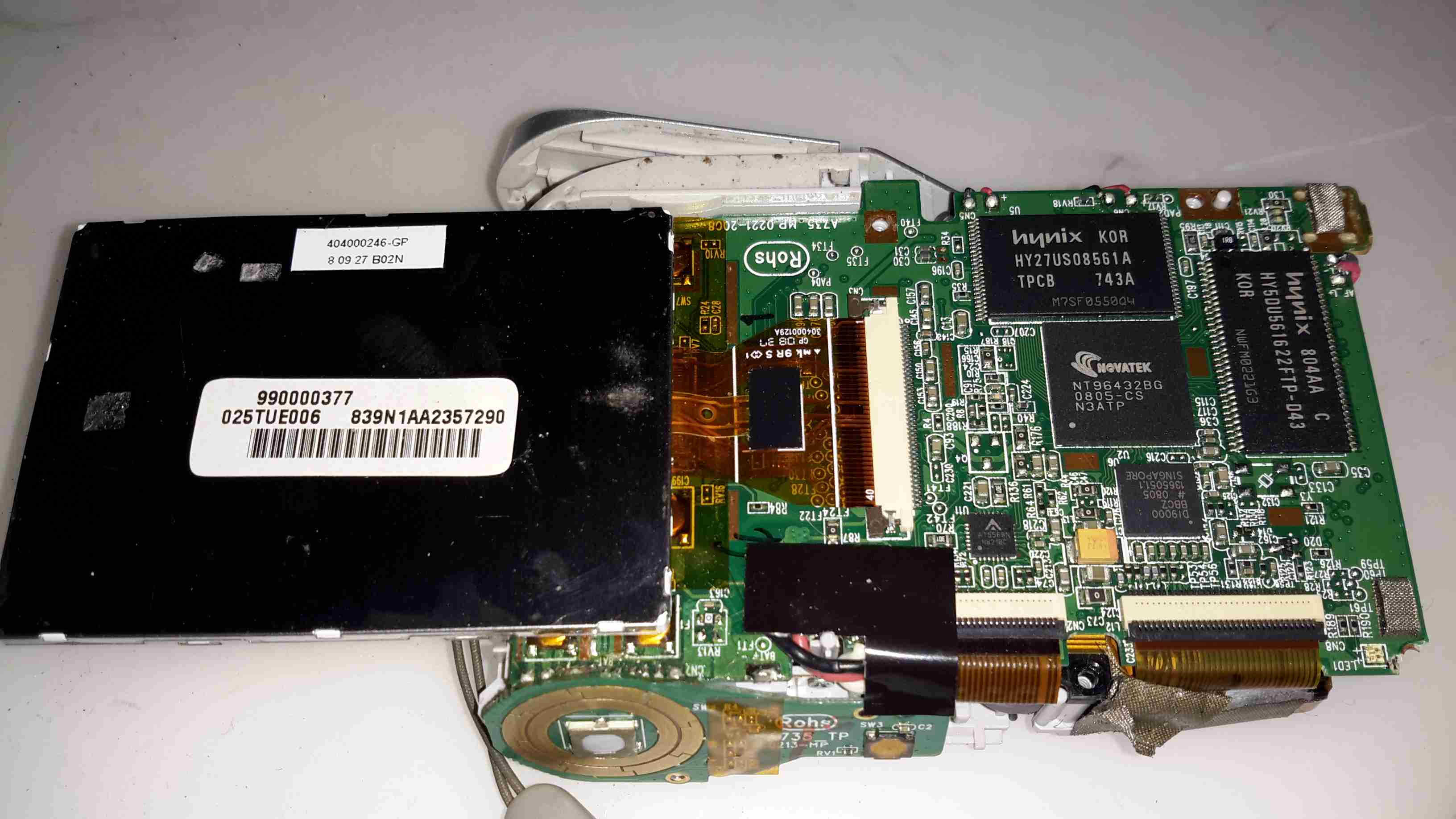
Main Chipset
Flipping the LCD out of it’s mounting bracket reveals the main camera chipset. The CPU is a NovaTek NT96432BG, no doubt a SoC of some kind, but I couldn’t find any information. Firmware & inbuilt storage is on a Hynix HY27US08561A 256MBit NAND Flash, with a Hynix HY5DU561622FTP-D43 256Mbit DRAM for system memory.
I couldn’t find any info on the other two chips on this side of the board, but one is probably a motor driver for the lens, while the other must be the front end for the CCD sensor input to the SoC.
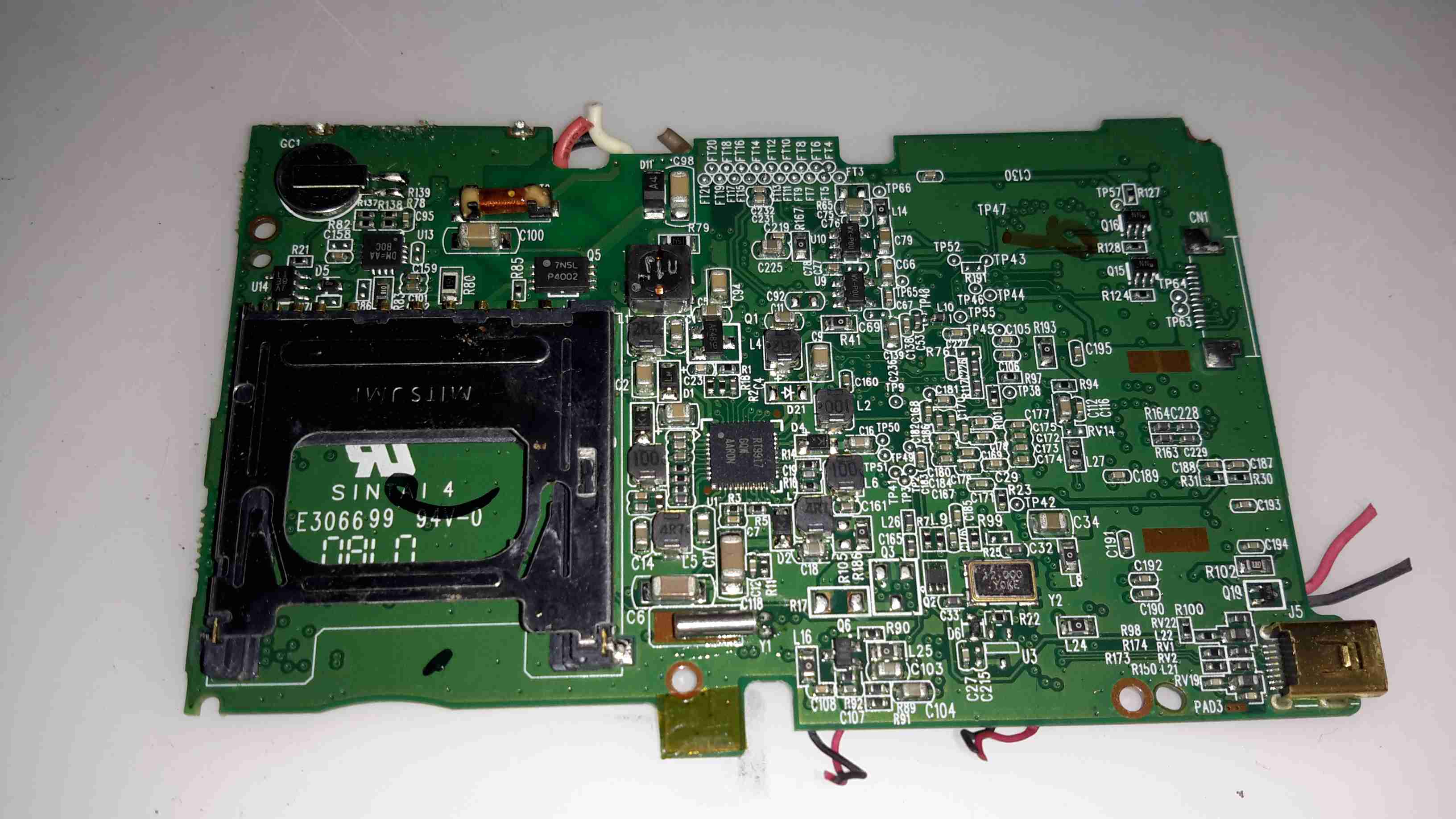
Main PCB Reverse
The other side of the PCB handles the SD card slot & power management. All the required DC rails are provided for by a RT9917 7-Channel DC-DC converter from RichTek, an IC designed specifically for digital camera applications.
Top left above the SD card slot is the trigger circuitry for the Xenon flash tube & the RTC backup battery.
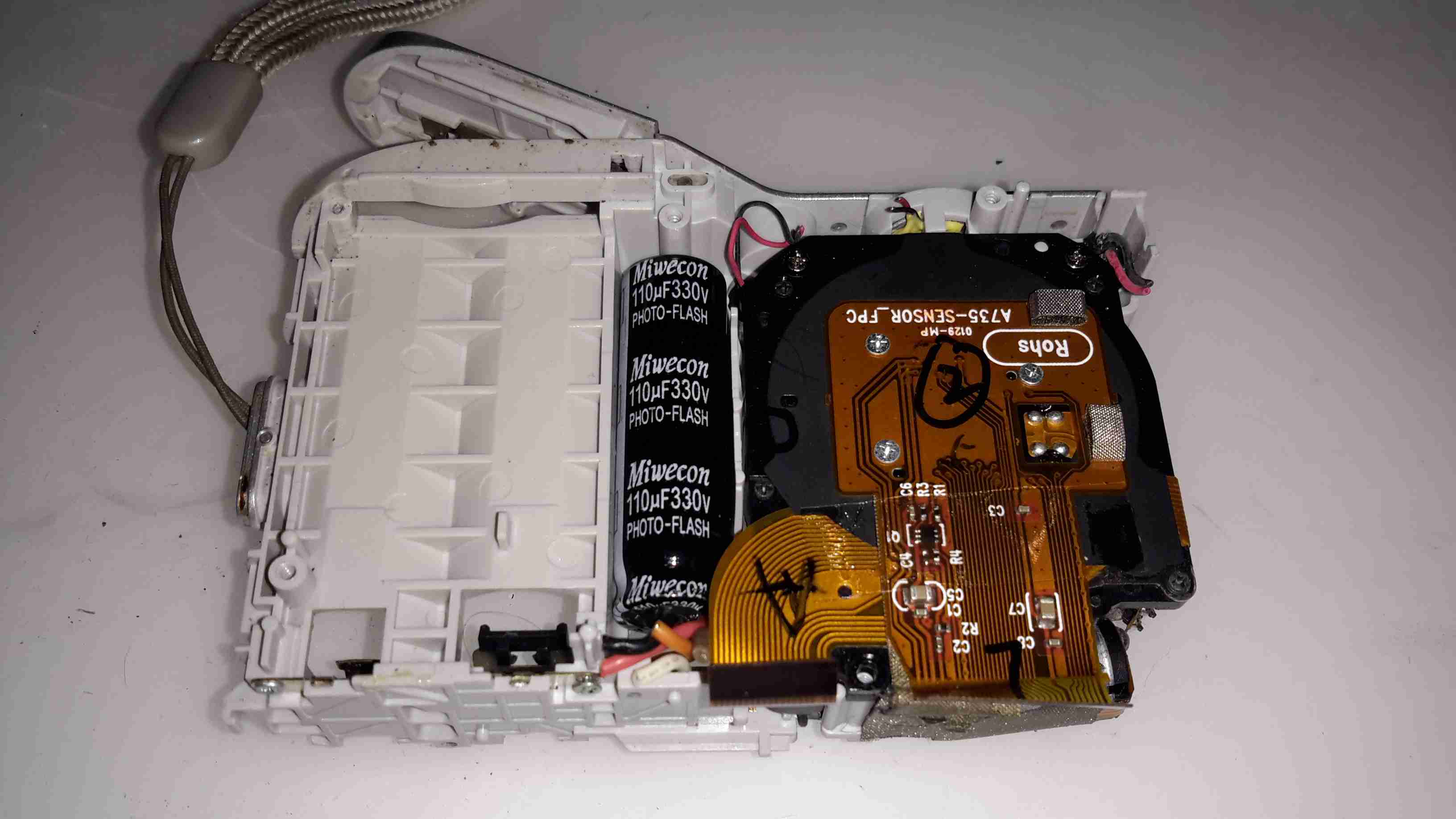
Main PCB Removed
Once the main PCB is out of the frame, the back of the lens module with the CCD is accessible. Just to the left is the high-voltage photoflash capacitor, 110µF 330v. These can give quite the kick when charged! Luckily this camera has been off long enough for the charge to bleed off.
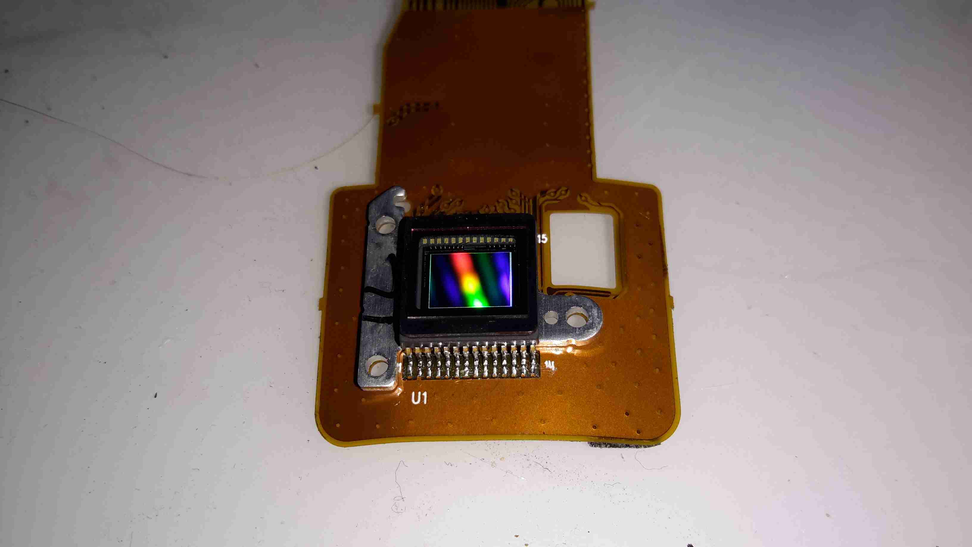
Sensor
Finally, here’s the 7-Megapixel CCD sensor removed from the lens assembly, with it’s built in IR cut filter over the top. I couldn’t find any make or model numbers on this part, as the Aluminium mounting bracket behind is bonded to the back of the sensor with epoxy, blocking access to any part information.
Die images of the chipset to come once I get round to decapping them!
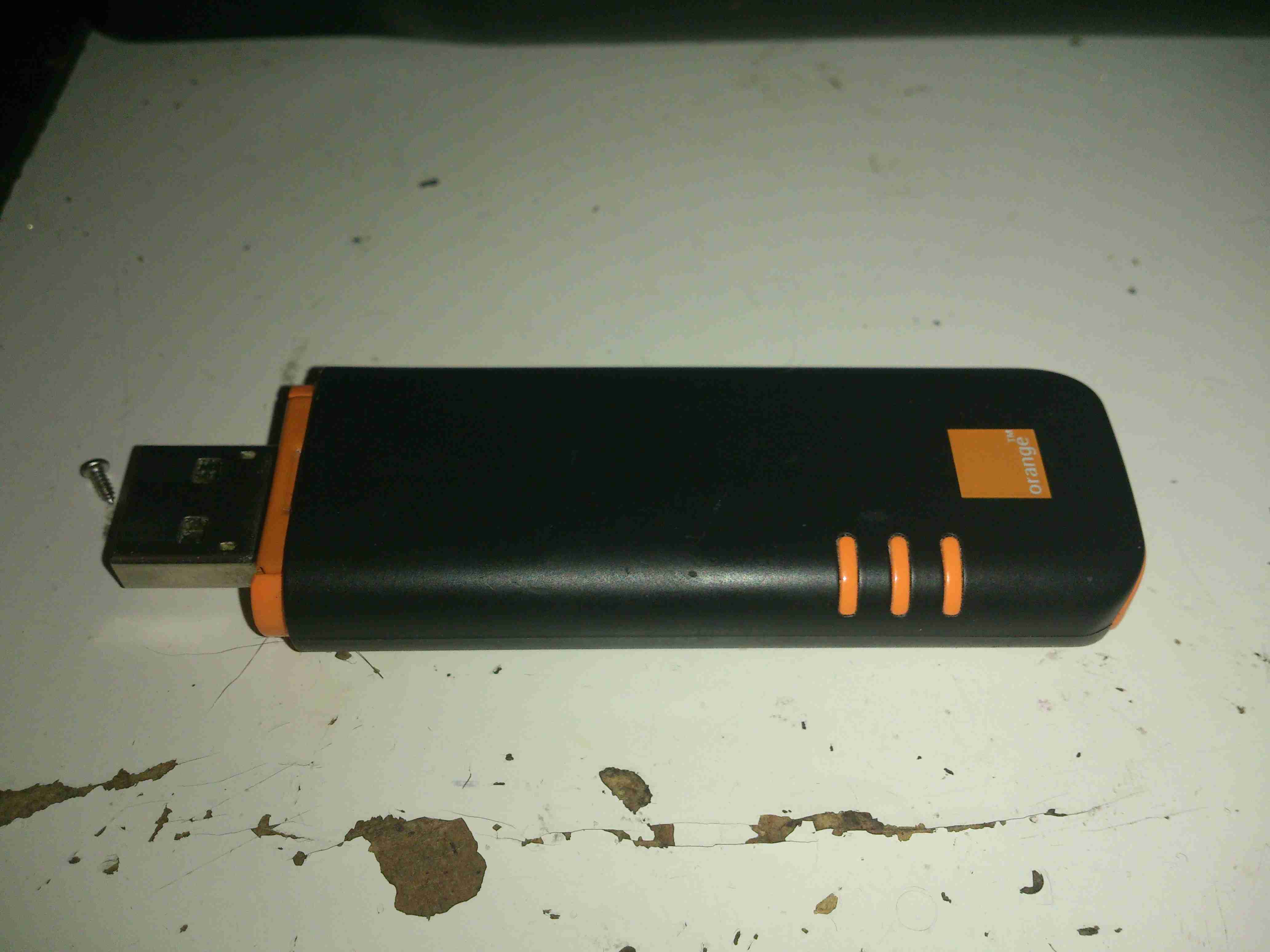
Here’s an old HDSPA 3G USB modem stick that I got with a mobile phone contact many years ago. As it’s now very old tech, and I have a faster modem, not to mention that I’m no longer with Orange (Robbing <expletive>), here’s a teardown of the device!
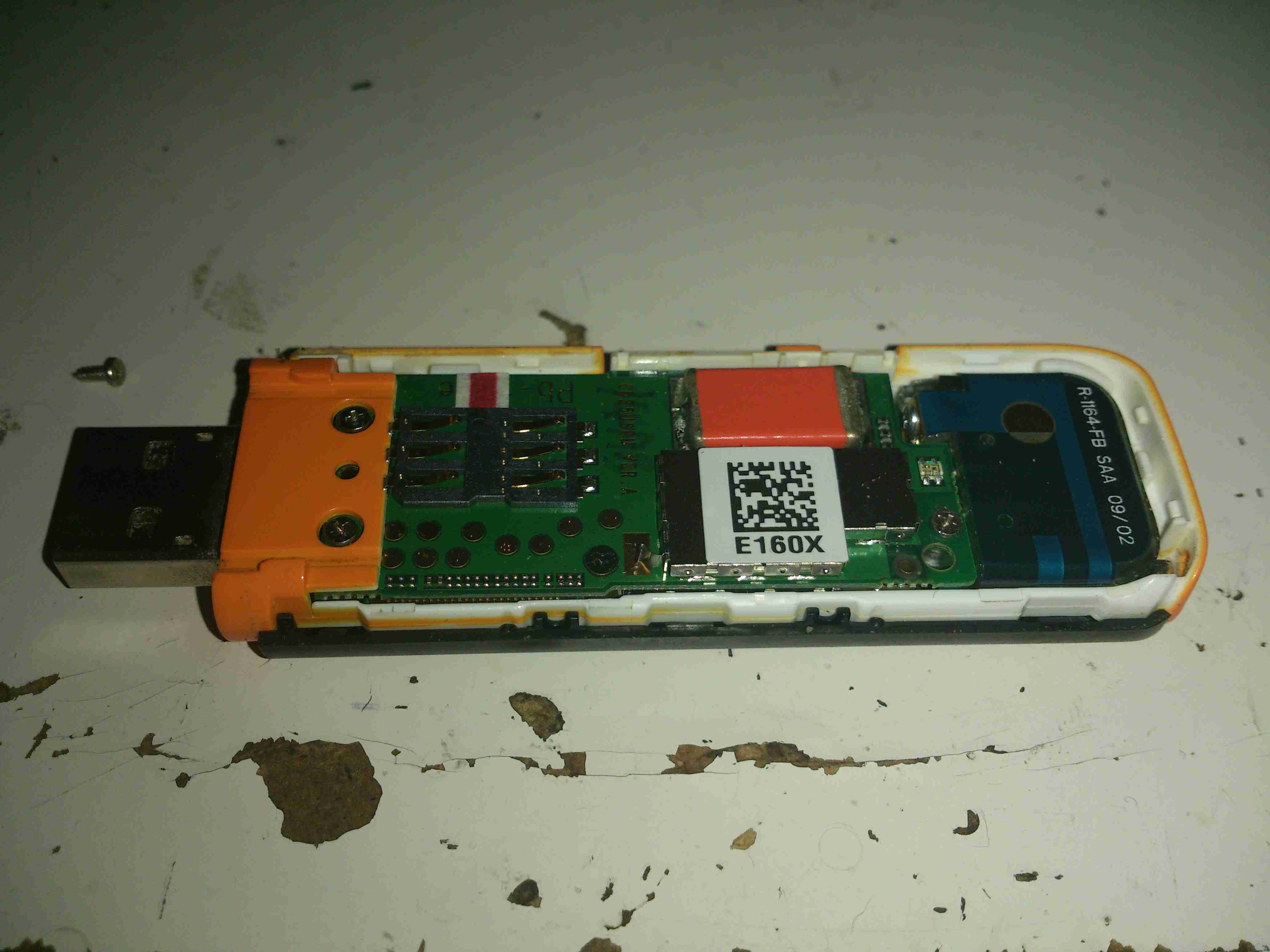
Cover Removed
The top shell is just clipped into place, while a pair of very small screws hold down the orange piece at left to hold the PCB stack in the casing. Not much to see here, but it’s clear that there’s a lot crammed into a very small space.
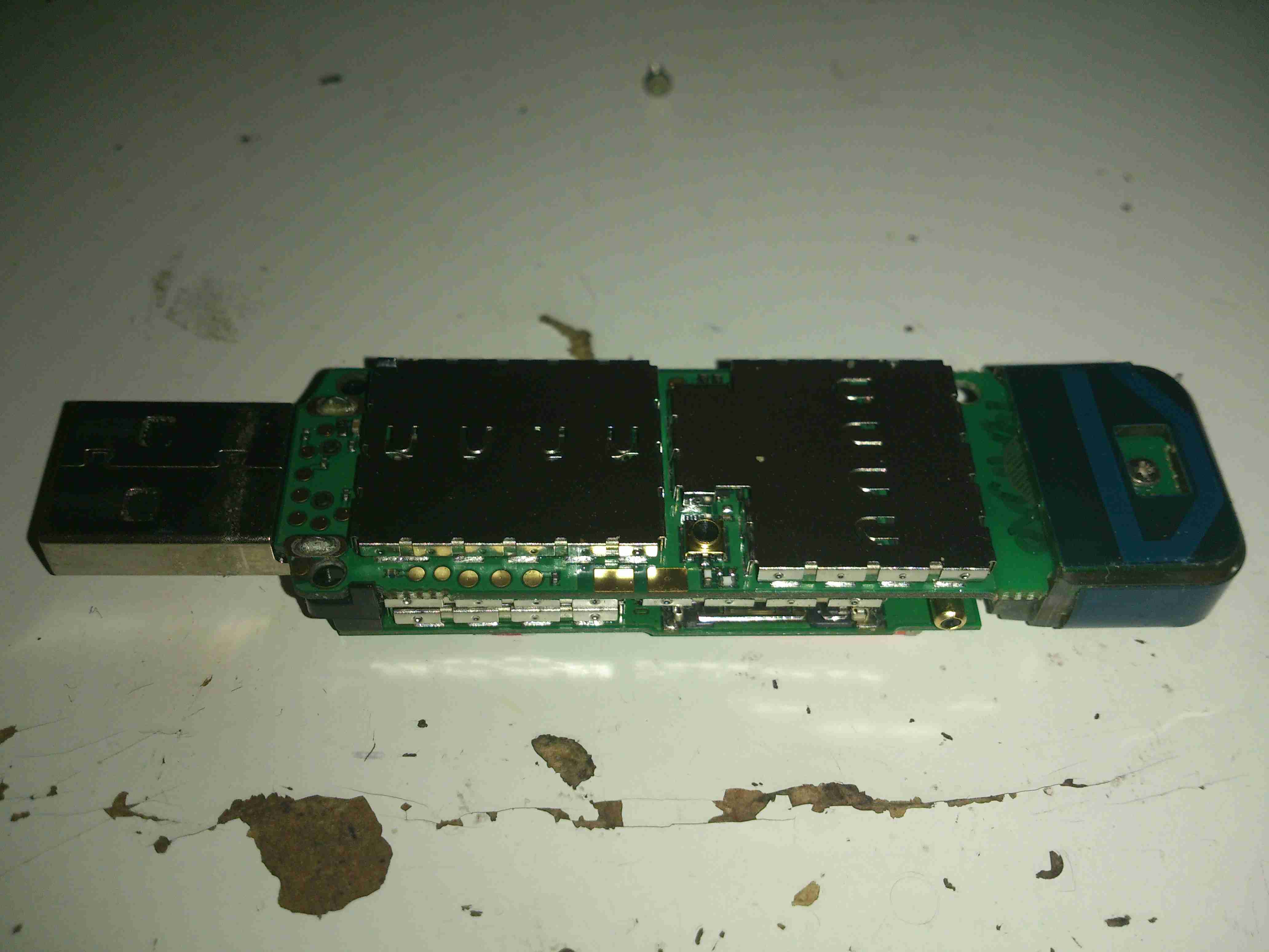
PCB Assembly
Here’s the PCB stack removed from the outer casing. The main antenna is on the right, attached with another small screw. Every IC on the boards is covered with an RF can. No problems there, pliers to the rescue!
SD Card Slot
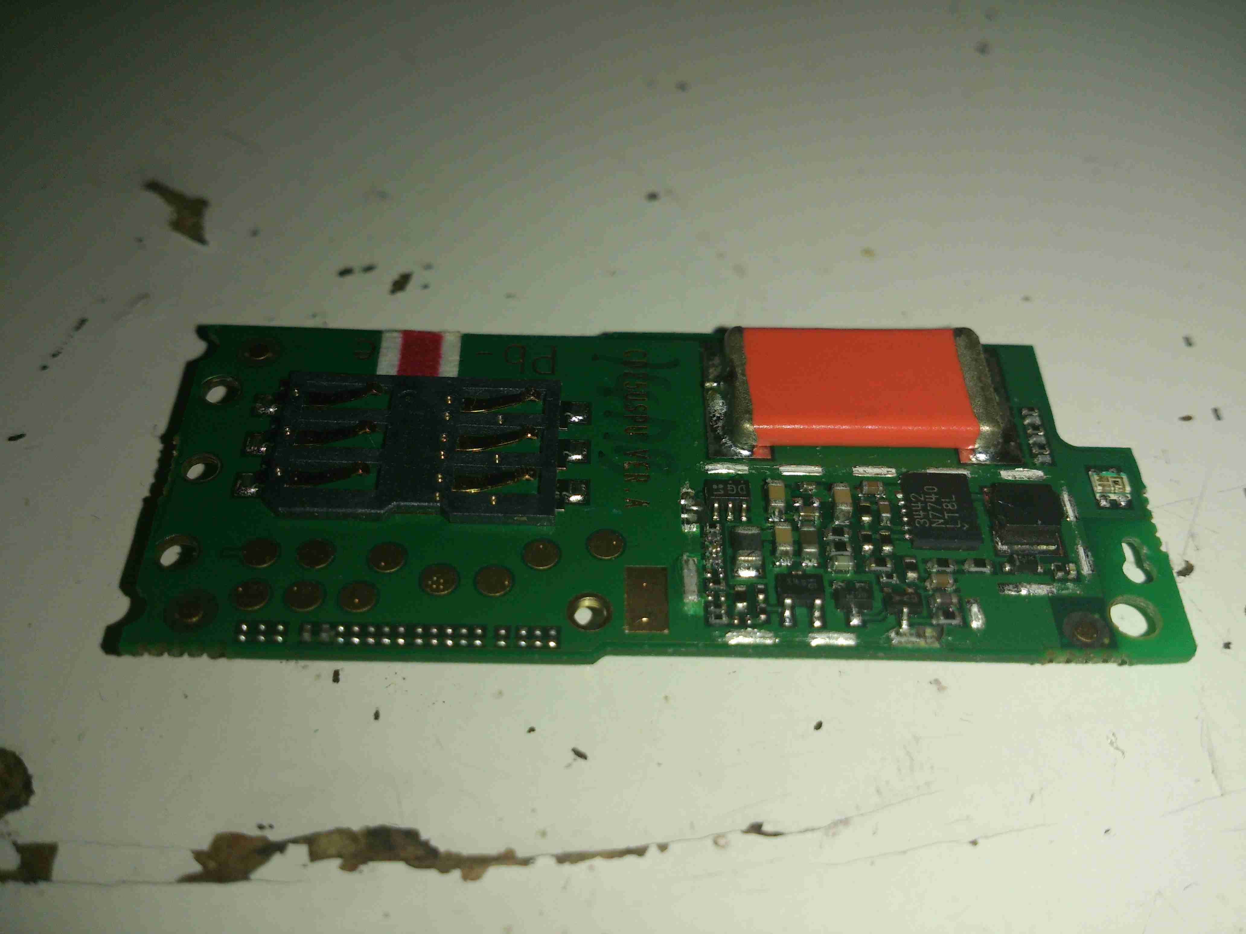
Here’s the top PCB, all the shields have been removed. On the left is a Qualcomm PM6658 Power Management IC with integrated USB transceiver. This is surrounded by many of the power management circuits.
The integrated SD Card slot is on the right side. with what looks to be a local switching regulator for supply voltage. This might also provide the SIM card with it’s power supply.
PSU & SIM Contacts
The other side of the top board reveals more power management, with another switching regulator, and a truly massive capacitor at the top edge. I’m guessing this is a solid Tantalum.
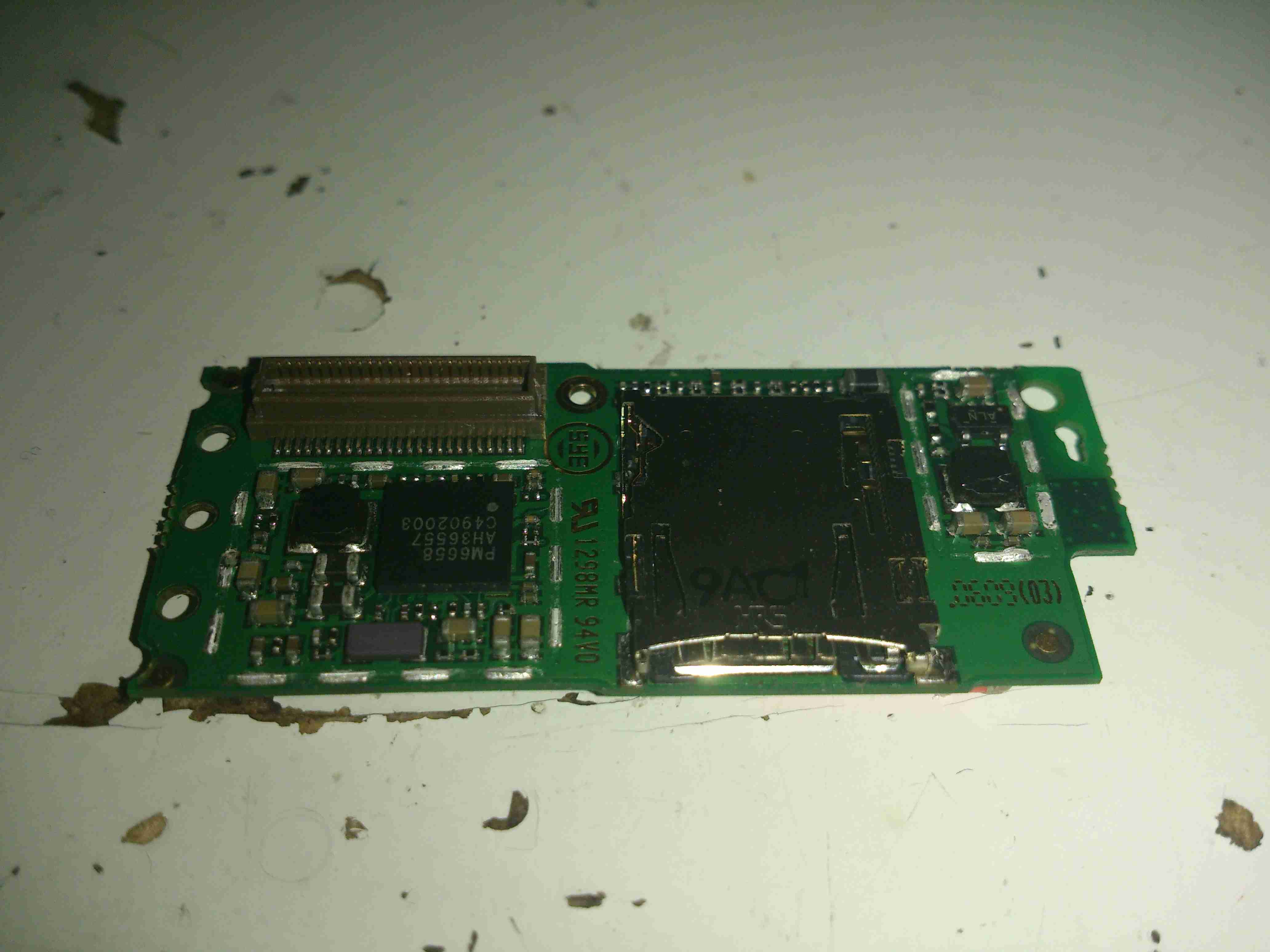
Main Chipset PCB
The other PCB holds the main chipset & RF circuits. On the left here is a Samsung MCP K5D1G13ACH IC. This one is a multiple chip package, having 1Gbit of NAND Flash & 512Mbit of mobile SDRAM.
To it’s right is a Qualcomm RTR6285 RF Transceiver. This IC supports multiband GSM/EDGE/UMTS frequencies & also has a GPS receive amplifier included.
At bottom right is an Avago ACPM7371 Wide-Band 4×4 CDMA Power Amplifier. The external antenna connector is top right.
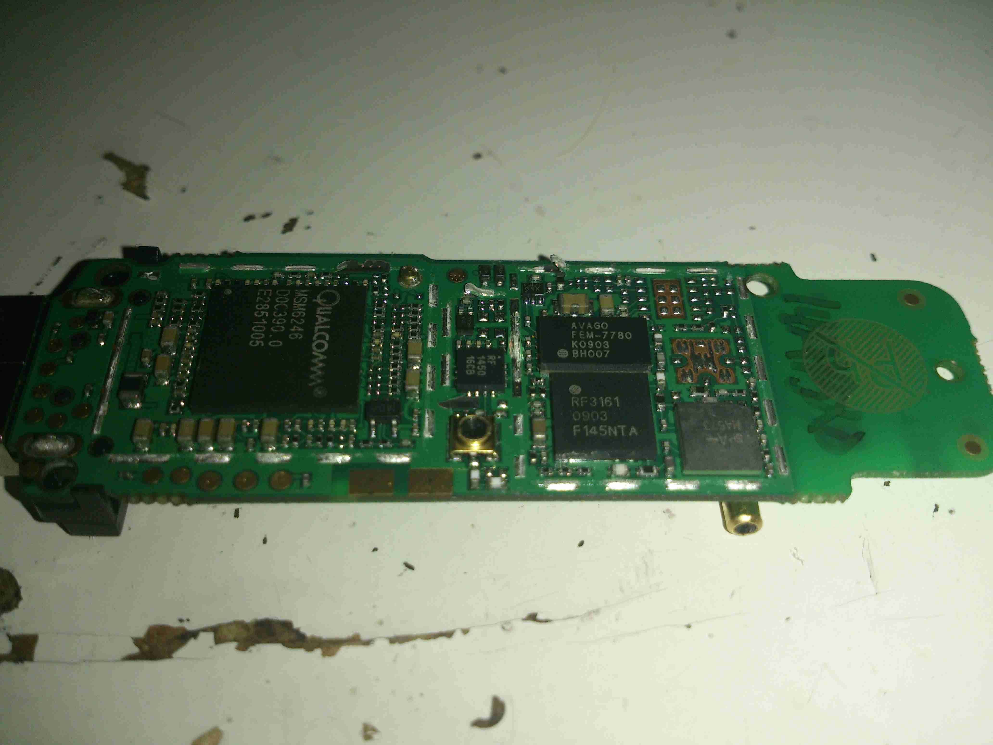
Main Chipset PCB Reverse
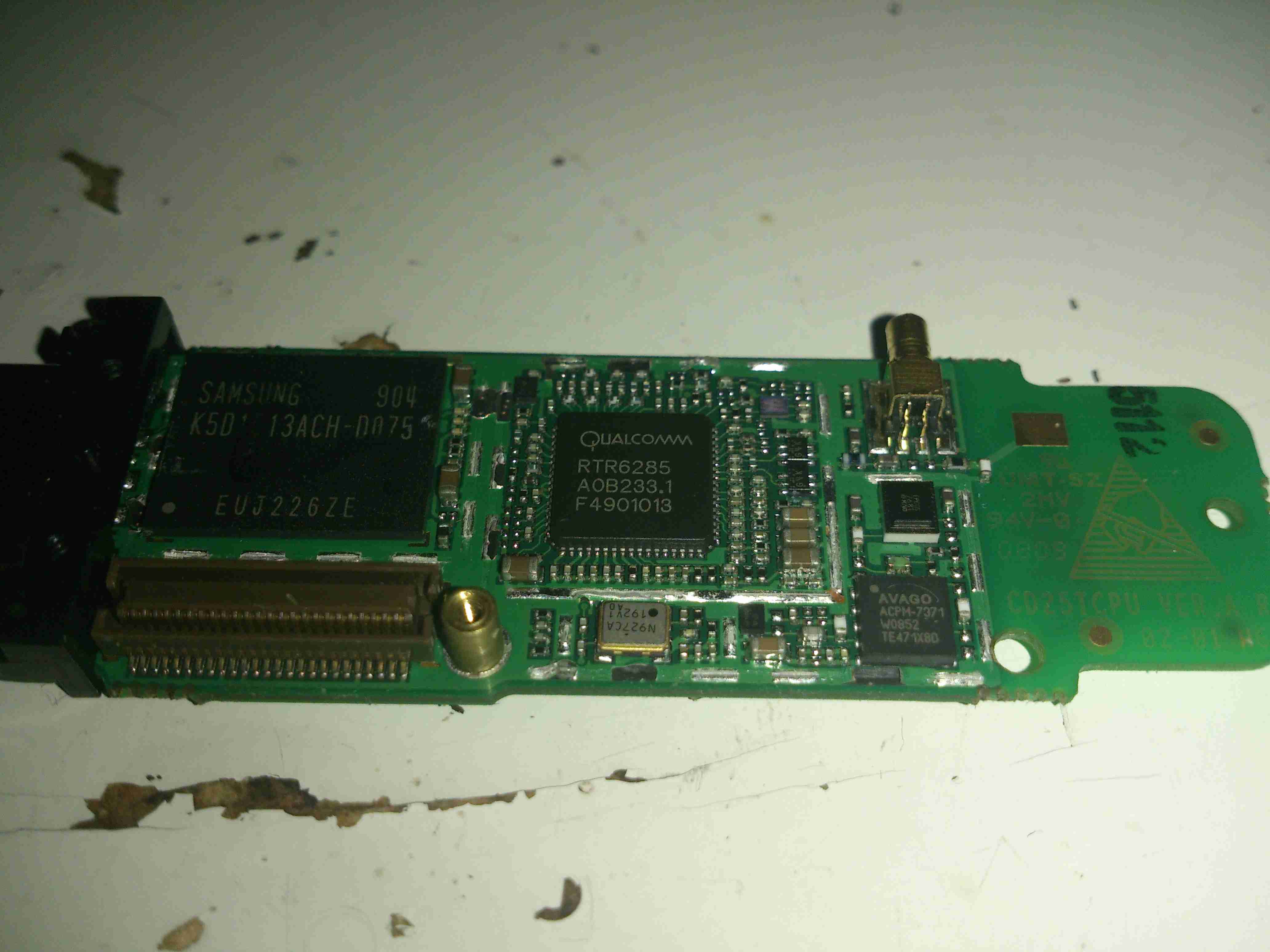
On the other side of the main PCB is a Qualcomm MSM6246 Baseband processor. Not sure about this one as I can’t find anything resembling a datasheet. Another micro-coax connector is in the centre, probably for factory test purposes, as it’s not accessible from the outside.
Just above the coax connector is a Qorvo RF1450 SP4T (single-pole 4-throw) High Power (34.5dBm) GSM RF Switch.
Upper right is an Avago FEM-7780 UMTS2100 4×7 Front End Module.
Under that is an RFMD RF3163 Quad-Band RF Power Amplifier Module.
I recently dug out my other card printer to fit it with a 12v regulator, (it’s 24v at the moment), and figured I’d do a teardown post while I had the thing in bits.
This is a less industrial unit than my Zebra P330i, but unlike the Zebra, it has automatic duplexing, it doesn’t have Ethernet connectivity though.
Unlike domestic printers, which are built down to a price, these machines are very much built up to a spec, and feature some very high quality components.
Naked Printer
Here’s the mechanism with the cowling removed. This is the main drive side of the printer, with the main drive stepper at left, ribbon take-up spool motor lower right, and the duplex module stepper motors at far right.
Main Motor Drive
The main drive motor runs the various rollers in the card path through a pair of synchronous belts, shown here.
Main Stepper
The stepper itself is a quality ball-bearing Sanyo Denki bipolar motor.
Main Stepper Driver
Electrical drive is provided to the stepper with a L6258EX DMOS universal motor driver. This chip can also drive DC motors as well as steppers.
Ribbon Supply Spool
Here is the encoder geared onto the ribbon supply spool. This is used to monitor the speed the ribbon is moving relative to the card.
Printer Top
Here’s a top view through the printer, the blue roller on the left cleans the card as it’s pulled from the feeder, the gold coloured spool to it’s right is the ribbon supply reel. The cooling fan on the right serves to stop the print head overheating during heavy use.
Spool Take Up Motor
The spool take-up reel is powered by another very high quality motor, a Buhler DC gearmotor. These printers are very heavily over engineered!
This motor drives the spool through an O-Ring belt, before the gear above. This allows the drive to slip in the event the ribbon jams, preventing it from breaking.
Duplex Unit Stepper Drivers
The pair of steppers that operate the duplexing unit are driven by a separate board, with a pair of L6219DS bipolar stepper driver ICs. There are also a couple of opto-sensors on this board for the output hopper.
Main Control PCB
All the mechanisms of the printer are controlled from this main PCB, which handles all logic & power supply functions. Sections on the board are unpopulated, these would be for the Ethernet interface, smart card programming & magstripe programming.
Main CPU
The brains of the operation is this ColdFire MCF5208CVM166 32-bit microprocessor. It features 16KB of RAM, 8KB of cache, DMA controller, 3 UARTs, SPI, 10/100M Ethernet and low power management. This is a fairly powerful processor, running at 166MHz.
It’s paired with an external 128Mbit SDRAM from Samsung, and a Spansion 8Mbit boot sector flash, for firmware storage.
USB Interface & Power Input
Here the USB interface IC is located. It’s a USBN9604 from Texas Instruments, this interfaces with the main CPU via serial.
There have been quite a few updates to the hosting solution for this site, which is hosted locally in my house, from the above setup, in a small comms rack, to a new 22U half rack, with some hardware upgrades to come.
Core Switch Disconnected
Core switch here has been removed, with the rest of the core network equipment. The site was kept online by a direct connection into the gateway to the intertubes.
Switching Gear Installed
New 22U rack, with the core switch, FC switch & management & monitoring server installed.
Router Going In
As I had no rack rails to start with, the servers were placed on the top of the rack to start off, here is the Dell PowerEdge 860 pfSense core router installed, with the initial switch wiring to get the internal core network back online. This machine load balances two connections for an aggregated bandwidth of 140MB/s downstream & 15MB/s upstream.
The tower server behind is the NAS unit that runs the backups of the main & auxiliary webservers.
Almost Done
Still with no rack kits, all the servers are placed on top of the rack, before final installation. This allows running of the network before the rest of the equipment was installed.
The main server & aux server are HP ProLiant DL380 G3 servers, with redundant network connections.
Still to arrive are the final rack kits for the servers & a set of HP BL20p Blade servers, which will be running the sites in the future.
Here’s the teardown of the projector itself! On the right is the info label from the projector, which covers the flex ribbon to the VGA/composite input board below.
This unit is held together with Allen screws, but is easy to get apart.
PicoP Display Engine
Here’s the insides of the projector, with just the top cover removed. The main board can be seen under the shielding can, the Micro HDMI connector is on the left & the MicroUSB connection is on the right. The USB connection is solely for charging the battery & provides no data interface to the unit.
On top of the main board is the shield can covering the PicoP Display Engine driver board, this shield was soldered on so no peek inside unfortunately!
Laser Module
The laser module itself is in the front of the unit, the laser assemblies are closest to the camera, on the left is the Direct Doubled Green module, in the centre is the blue diode, and the red diode on the right. Inside the module itself is an arrangement of mirrors & beamsplitters, used to combine the RGB beams from the lasers into a single beam to create any colour in the spectrum.
Module Innards
Here is the module innards revealed, the laser mounts are at the top of the screen, the green module is still mounted on the base casting.
The three dichroic mirrors in the frame do the beam combining, which is then bounced onto the mirror on the far left of the frame, down below the MEMs. From there a final mirror directs the light onto the MEMs scanning mirror before it leaves through the output window.
A trio of photodiodes caters for beam brightness control & colour control, these are located behind the last dichroic turning mirror in the centre of the picture.
Green Module Cavity
This is inside the green laser module, showing the complexity of the device. This laser module is about the size of a UK 5p coin!
Green Module Labeled
And here on the left is the module components labelled.
Main PCB Top
Here is the main PCB, with the unit’s main ARM CPU on the right, manufactured by ST.
User buttons are along the sides.
Main PCB Bottom
Other side of the main board, with ICs that handle video input from the HDMI connector, battery charging via the USB port & various other management.
Tip Jar
If you’ve found my content useful, please consider leaving a donation by clicking the Tip Jar below!
All collected funds go towards new content & the costs of keeping the server online.