Posted on Leave a comment

Official Raspberry Pi 7″ Touch LCD

Raspberry Pi LCD
Raspberry Pi LCD

Finally the Raspberry Pi Foundation have released an official LCD for the DSI connector on the Pi. When these were announced, I placed an order straight away, but due to demand it’s taken quite a while for it to arrive in the post.
Interface PCB
Interface PCB

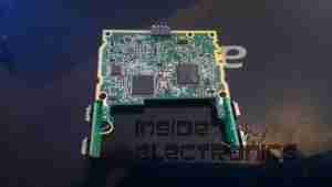
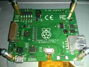
The LCD itself is an RGB panel, to interface the Pi via the MIPI DSI port, some signal conversion is required. A small PCB is mounted on the back of the LCD to do this conversion. It also handles the power supply rails required by the LCD itself & interfacing the touch screen.
LCD Power Supply
LCD Power Supply

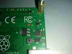
Taking care of the power supply is a Texas Instruments TPS65101 triple output LCD power supply IC. This also has a built in linear regulator to supply 3.3v for the rest of the circuitry on board. The large transistor to the left of the IC is the pass transistor for this regulator.
Main Controller
Main Controller

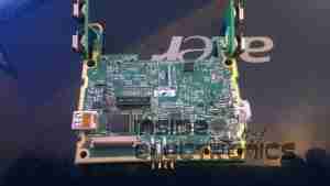
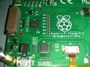
The video signal comes in on the FFC connector on the left, into the BGA IC. I’ve not managed to identify this component, but it’s doing the conversion from serial video from the Pi to parallel RGB for the LCD.
There’s also an Atmel ATtiny88 on the board below the main video conversion IC, not sure what this is doing.
The touch controller itself is mounted on the flex of the LCD, in this case it’s a FT5406.

Raspberry Pi LCD
Raspberry Pi LCD

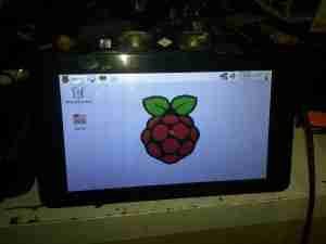
Here’s the LCD in operation. It’s not the highest resolution out there, but it leaves the GPIO & HDMI ports free for other uses.
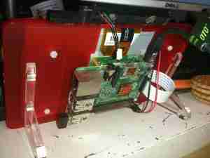
Pi Mounted
Pi Mounted

The Pi screws to the back of the LCD & is connected with a flat flex cable & a pair of power jumpers. I’ve added a couple of small speakers to the top edge of the LCD to provide sound. (More to come on this bit).
 

Posted on Leave a comment

445nm Laser TTL Interface

TTL Interface
TTL Interface

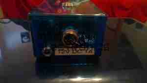
In preparation for my laser scanner project, I have modified my existing 445nm laser to accept a TTL blanking input. The laser driver is already enabled for this & just required an extra connection to interface with my laser scanner showboard. I have used an 8-pin connection to allow the same cable & interface to be used with an RGB laser system, when it arrives. The signals are as follows, from top centre, anti-clockwise:

Pin 1: +12v Power
Pin 2: Blue TTL
Pin3: GND
Pin 4: Green TTL
Pin 5: GND
Pin 6: Red TTL
Pin 7: GND
Centre: Power GND


Custom TTL Cable
Custom TTL Cable

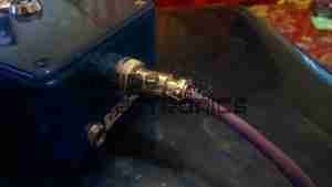
Here is the custom 8 core cable, which connects to the laser scanner show board. This cable allows the laser to be used for projection while still retaining the portable function & the keylock arming switch. When plugged in the cable bypasses the keyswitch & provides 12v DC direct to the laser driver.

Posted on 1 Comment

MicroVision ShowWX+ HDMI Laser Pico Projector

Info
Info

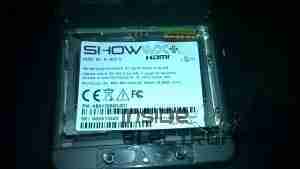
Here’s the teardown of the projector itself! On the right is the info label from the projector, which covers the flex ribbon to the VGA/composite input board below.

This unit is held together with Allen screws, but is easy to get apart.


PicoP Display Engine

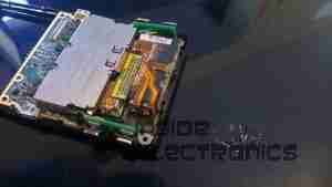
Here’s the insides of the projector, with just the top cover removed. The main board can be seen under the shielding can, the Micro HDMI connector is on the left & the MicroUSB connection is on the right. The USB connection is solely for charging the battery & provides no data interface to the unit.

On top of the main board is the shield can covering the PicoP Display Engine driver board, this shield was soldered on so no peek inside unfortunately!

Laser Module
Laser Module

The laser module itself is in the front of the unit, the laser assemblies are closest to the camera, on the left is the Direct Doubled Green module, in the centre is the blue diode, and the red diode on the right. Inside the module itself is an arrangement of mirrors & beamsplitters, used to combine the RGB beams from the lasers into a single beam to create any colour in the spectrum.

Module Innards
Module Innards


Here is the module innards revealed, the laser mounts are at the top of the screen, the green module is still mounted on the base casting.
The three dichroic mirrors in the frame do the beam combining, which is then bounced onto the mirror on the far left of the frame, down below the MEMs. From there a final mirror directs the light onto the MEMs scanning mirror before it leaves through the output window.

A trio of photodiodes caters for beam brightness control & colour control, these are located behind the last dichroic turning mirror in the centre of the picture.

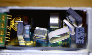
Green Module Cavity
Green Module Cavity

This is inside the green laser module, showing the complexity of the device. This laser module is about the size of a UK 5p coin!

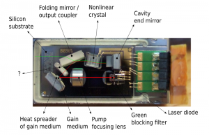
Green Module Labeled


And here on the left is the module components labelled.


Main PCB Top
Main PCB Top

Here is the main PCB, with the unit’s main ARM CPU on the right, manufactured by ST.

User buttons are along the sides.


Main PCB Bottom
Main PCB Bottom

Other side of the main board, with ICs that handle video input from the HDMI connector, battery charging via the USB port & various other management.


Posted on Leave a comment

£1 Shop LED Glitter Lamp

LED Glitter Lamp
LED Glitter Lamp

This is a decorative lamp from the £1 shop. Inside are RGB LEDs.

Internals
Internals

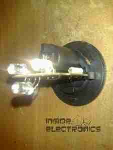
Internals removed from the base of the unit. The 3 LEDs are visible on the top & the tilt activation switch on the edge of the PCB.

IC
IC

Side of the PCB with the RGB controller IC, which is under a blob of epoxy.

Battery Holder
Battery Holder

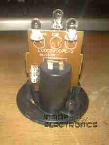
Reverse side of the PCB, showing the battery holder & the tilt switch. This runs on 3 button cells.