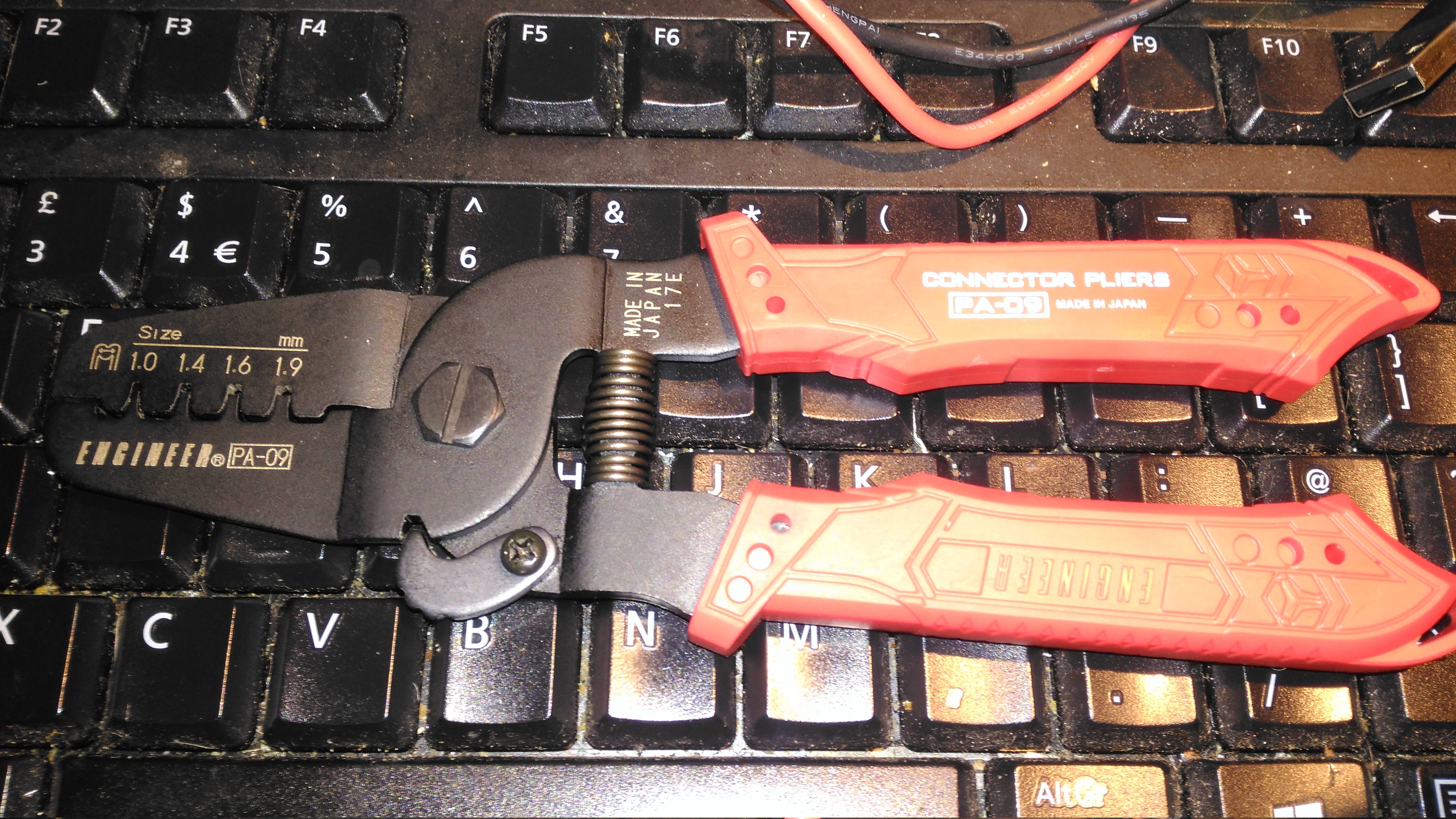
For a while now I’ve been attaching terminals such as Molex KK Dupont, & JST PH to wire ends with a lot of patience & a very fine soldering iron, however this method takes a lot of time, and with terminals like Dupont types, the terminal won’t fit into the connector body properly unless it’s crimped correctly. Official tools from the likes of JST or Molex are hilariously expensive, (~£250 for the Molex KK tool), and each tool only does a single connector series, so these are out of the picture. The cheapest available tool (~£40) for these types of terminals is the Engineer PA-09:
Engineer PA-09
These are simple crimping pliers, with no niceties like a ratchet mechanism, but nonetheless they work very well for the cost. The PA-09 can handle terminals from 1mm-1.9mm, there is another tool, the PA-21, which crimps terminals from 1.6mm-2.5mm. The fit & finish is good – proper steel (S55C high carbon steel according to Engineer), not the steel-plated-cheese that most cheap Chinese tools are fabricated from, the handles are solid & comfortable.
Handles
The rubber handles are press-fit onto the steel frame arms of the pliers, and don’t slip off readily.
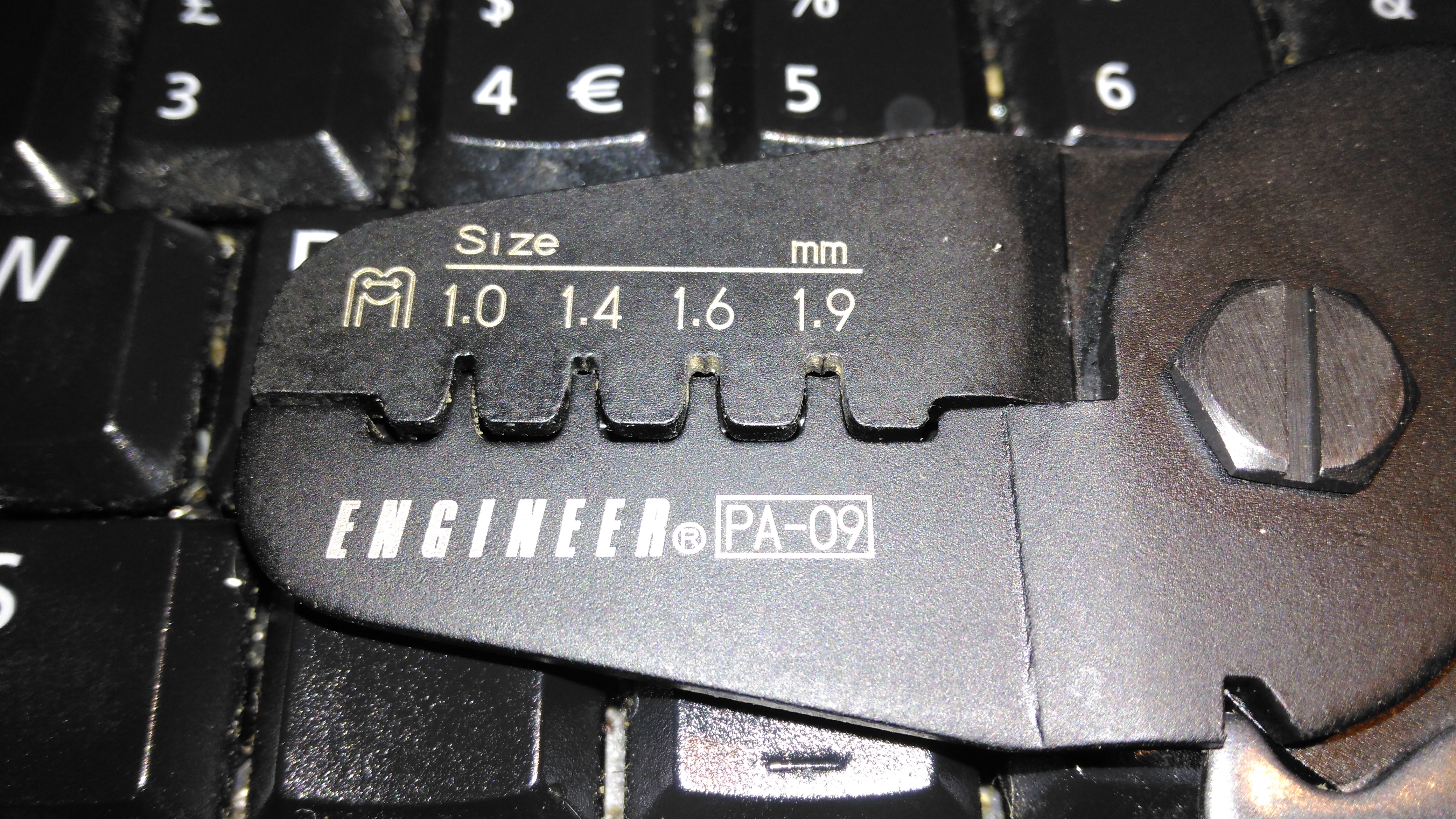
Die Head
The dies are well formed in the steel, and seem to be machined rather than stamped on a press, however the black oxide finish hides any machining marks. The smallest 1mm dies do seem to be a little fragile as they’re so small, so wouldn’t take much abuse without shearing off.
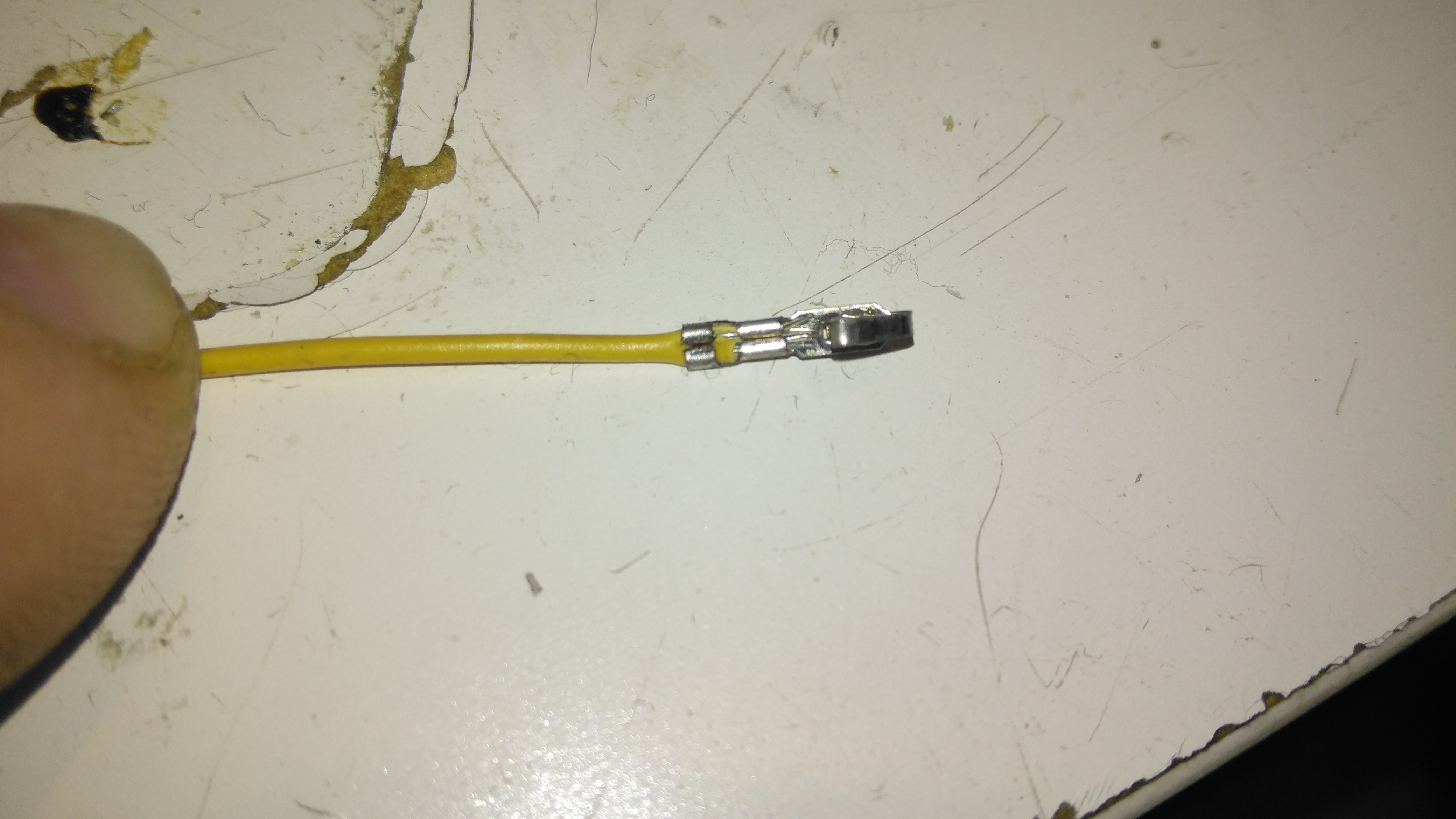
Crimped Molex KK Pin
Here’s a Molex KK pin that’s been crimped with the PA-09. The insulation crimp has pierced the insulation slightly, but this isn’t much of a problem. The conductor crimp is nice & tight, and everything is small enough to fit correctly into the plastic connector body. The trick with these tools is getting a feel for when the crimp is done – squeeze too tightly & the contact deforms, not tightly enough & the wire will just pull out of the terminal. The official tools also crimp both the conductor & insulation at the same time, and they also hold the terminal in place while the wire is inserted. In these cheaper tools, the crimps are done separately, but they do hold on to the contact securely enough for the wire to be inserted properly with your spare hand.
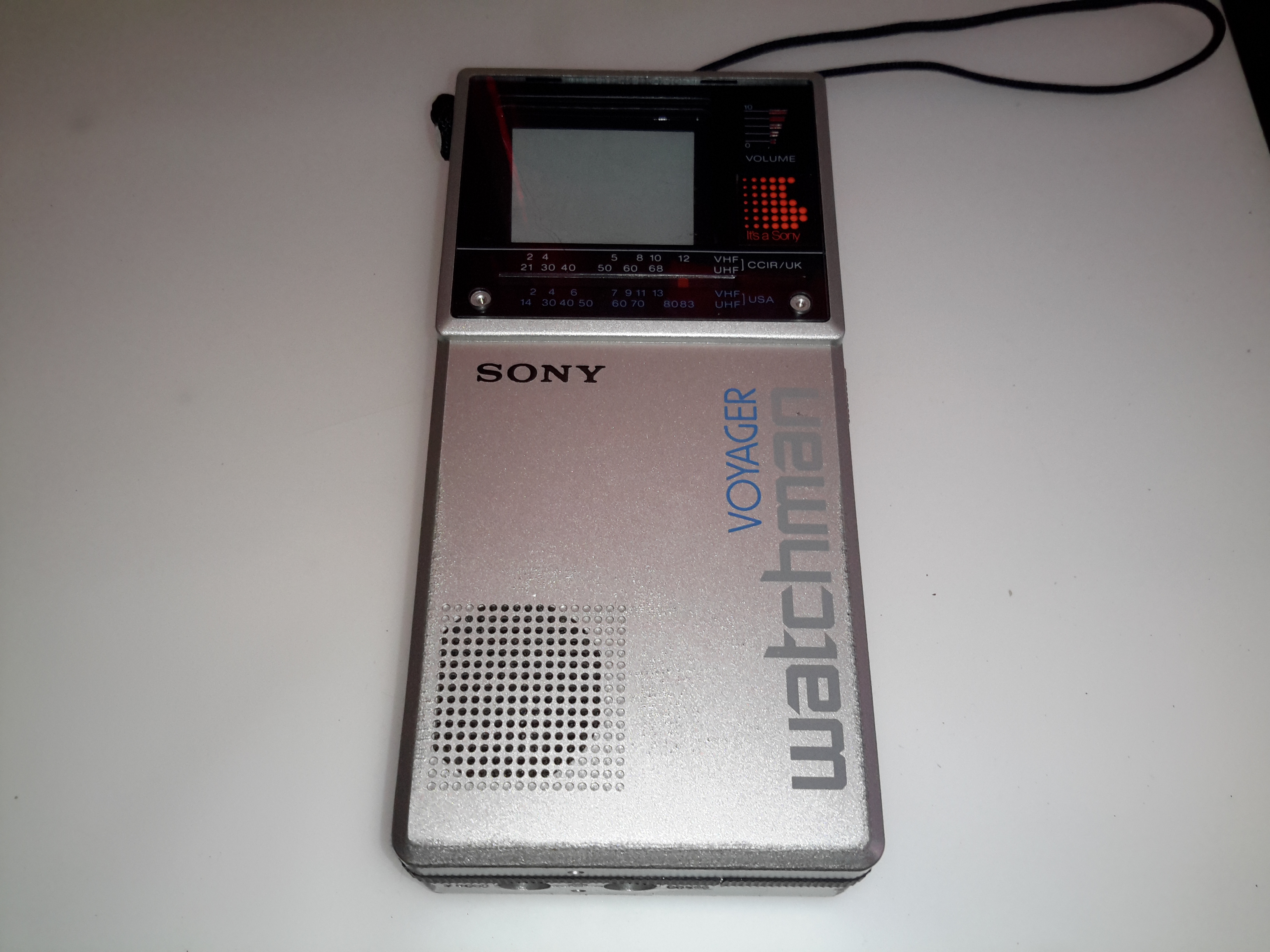
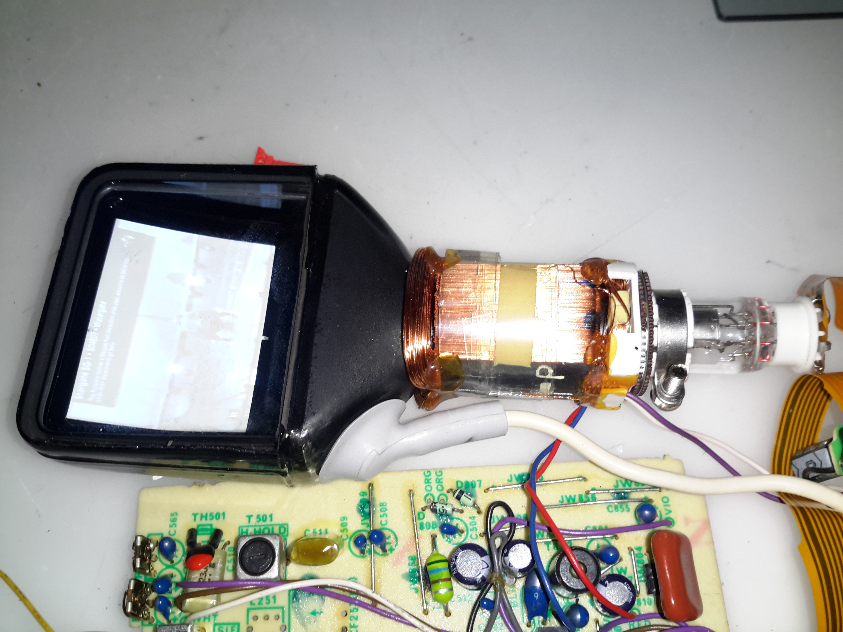
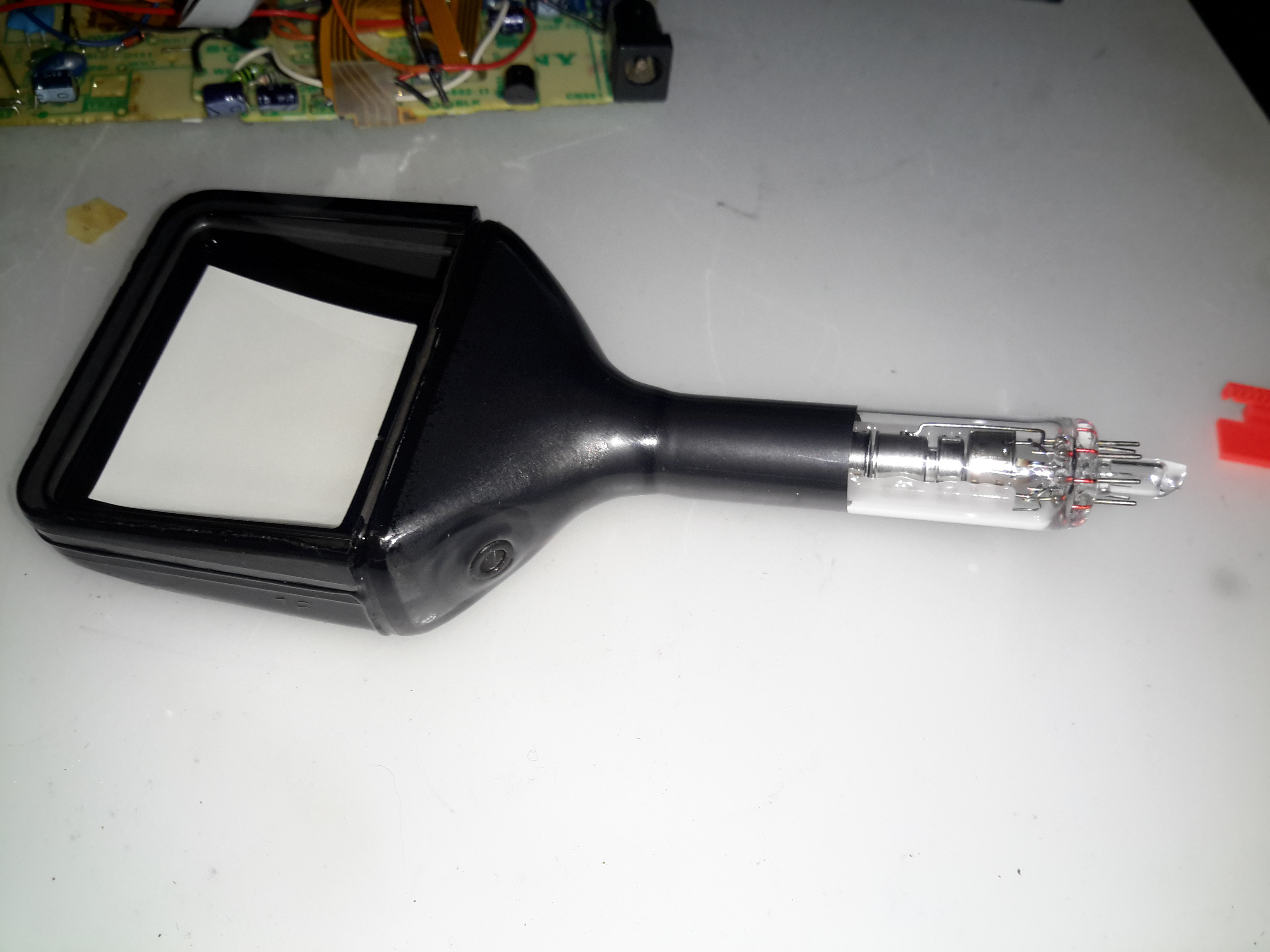
Here’s an oddity from the 1980’s – a CRT-based portable TV, with a very strangely shaped tube. Sony produced many types of flat CRTs back in the 80’s, with the electron gun at 90° to the curved phosphor screen.
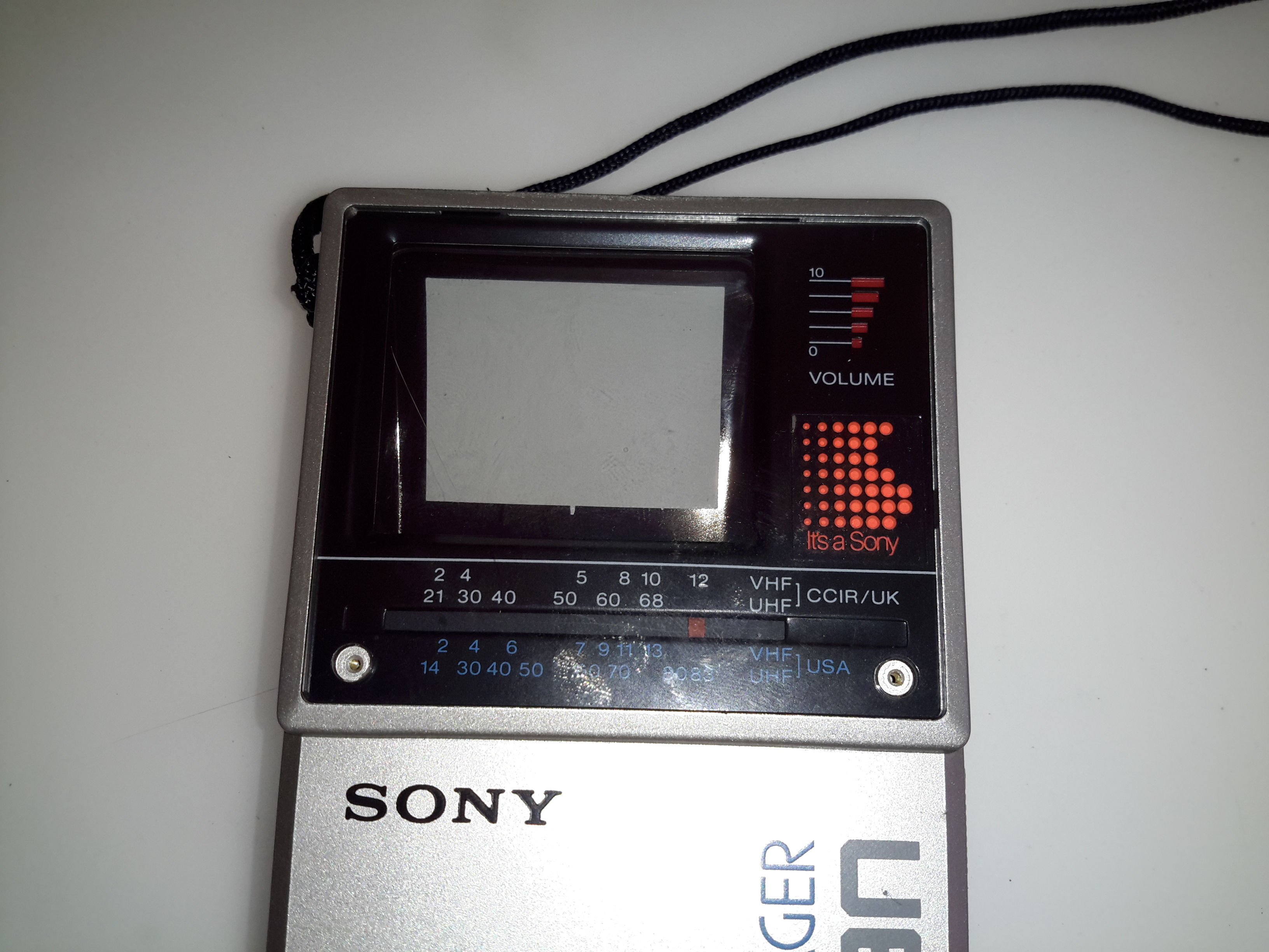
Front Panel
The front panel has the display window, along with the tuning & volume indicators. Unfortunately since analogue TV transmissions have long been switched off, this unit no longer picks up any transmissions off the air, but it can be modified to accept a composite video input.
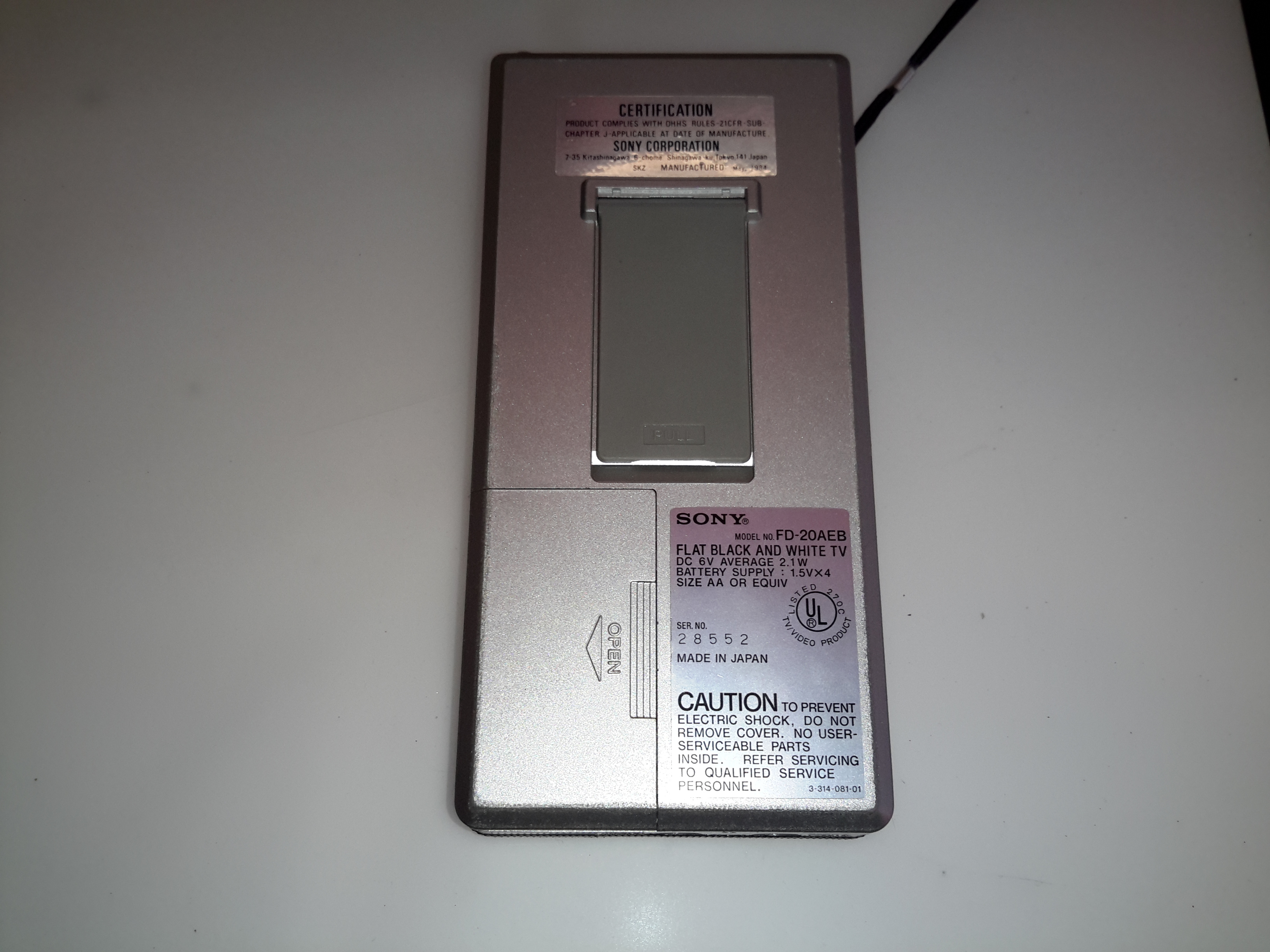
Back Panel
The back panel has the battery compartment & the tilt stand.
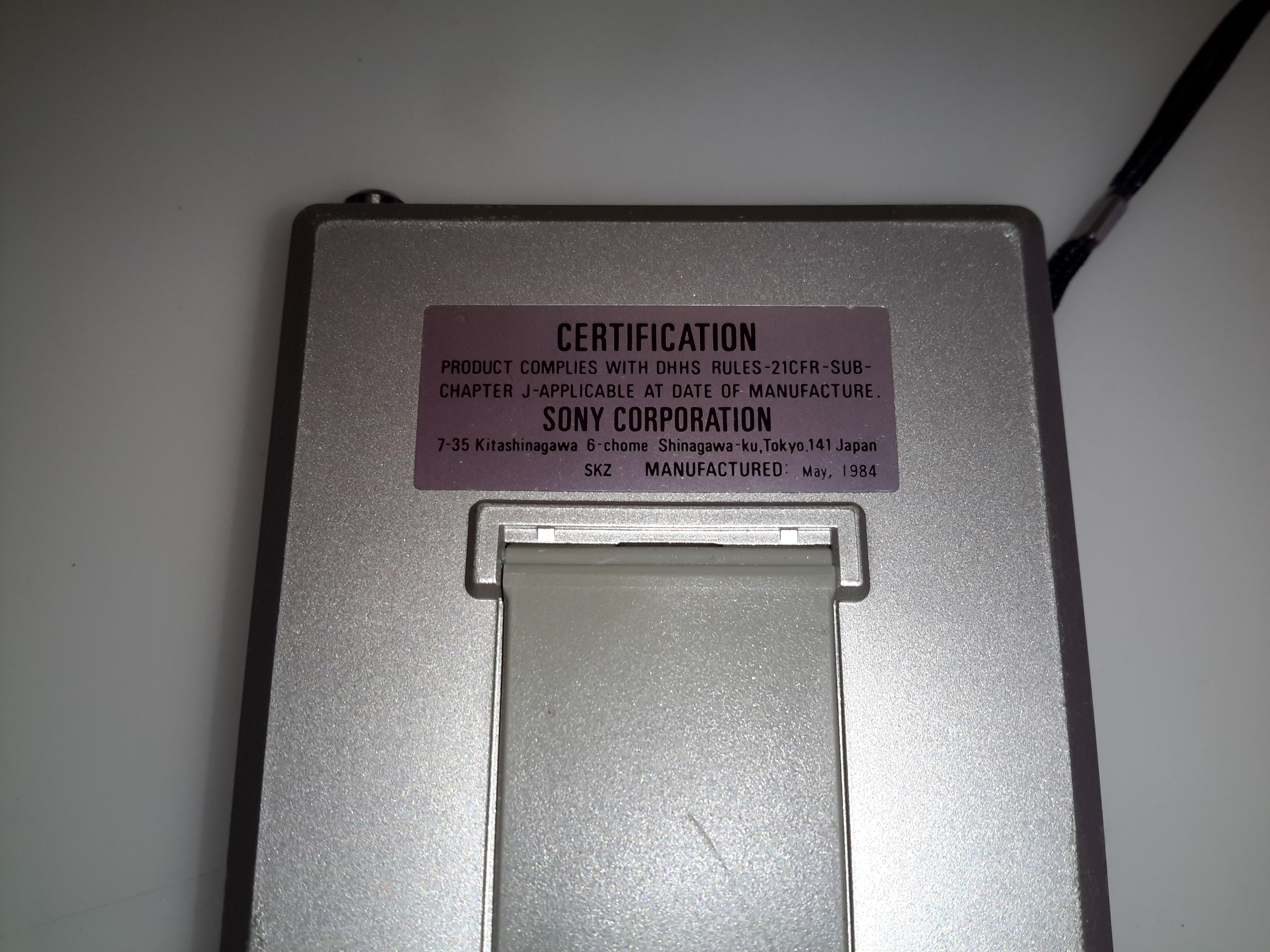
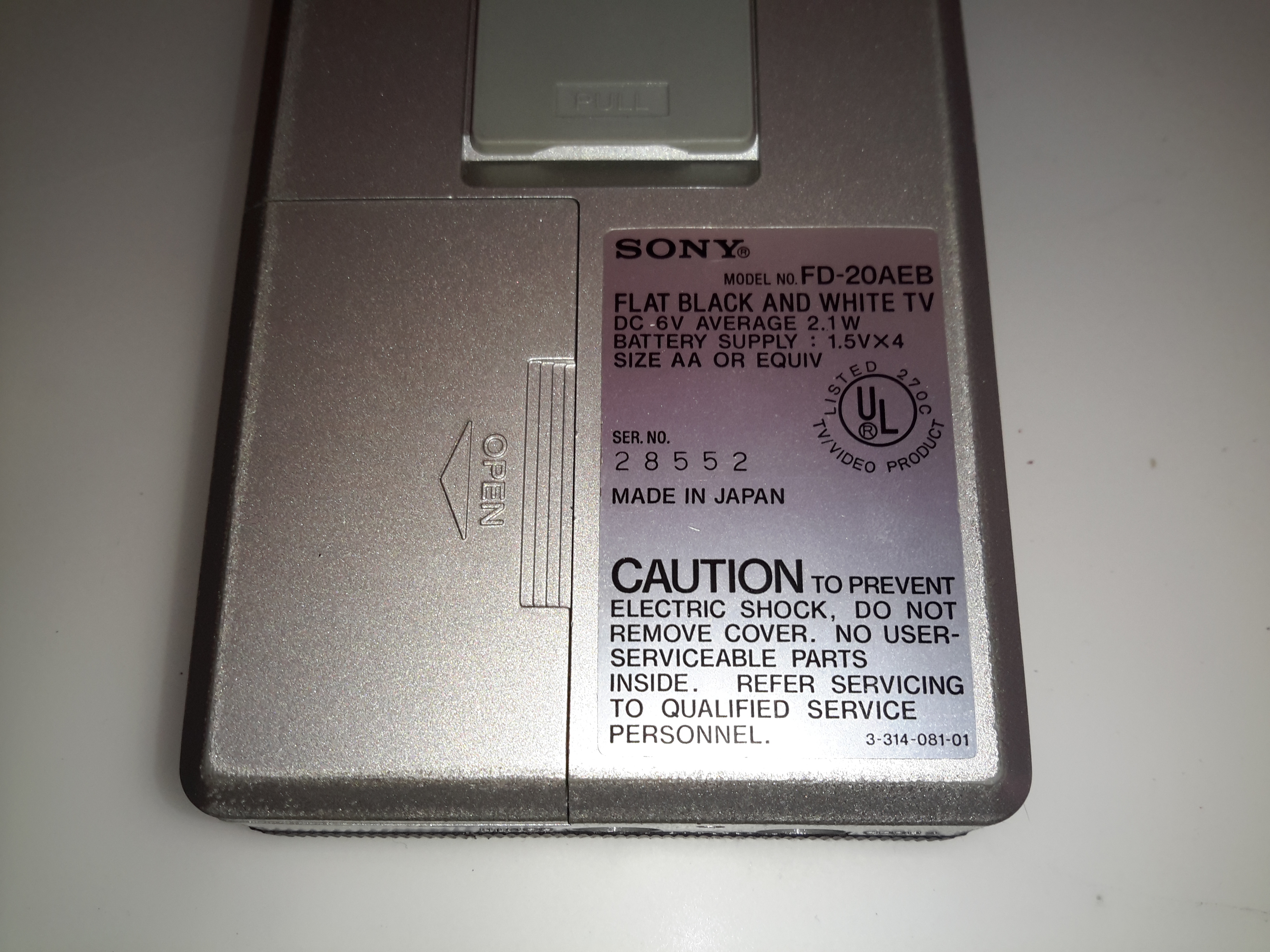
Certification
The certification label reveals this unit was manufactured in May 1984, 32 years ago!
Spec. Label
Rated at 6v, ~2.1W this device uses surprisingly little power for something CRT based.
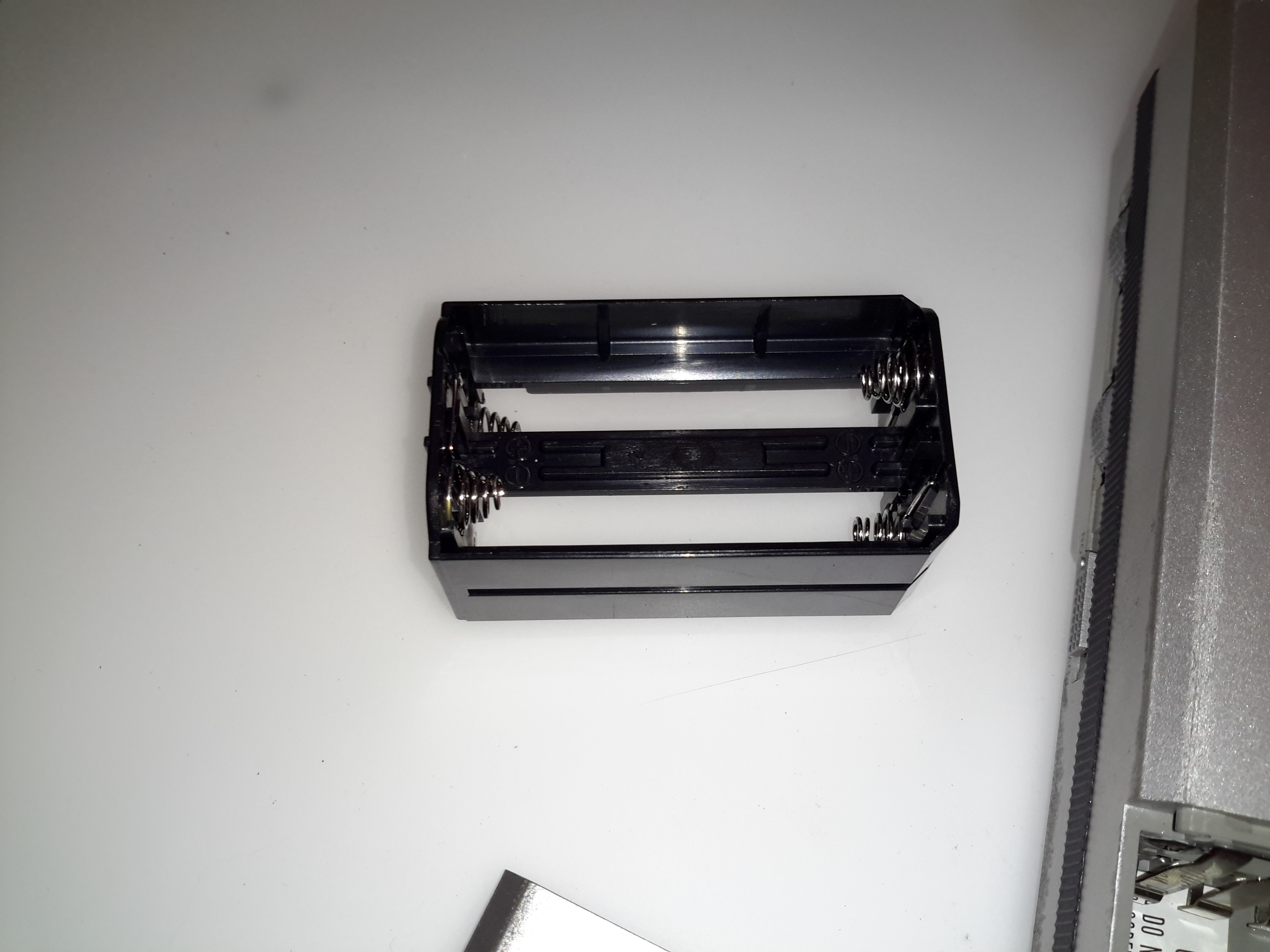
Battery Holder
The battery holder is a little unique, this plastic frame holds 4 AA cells, for a 6v pack.
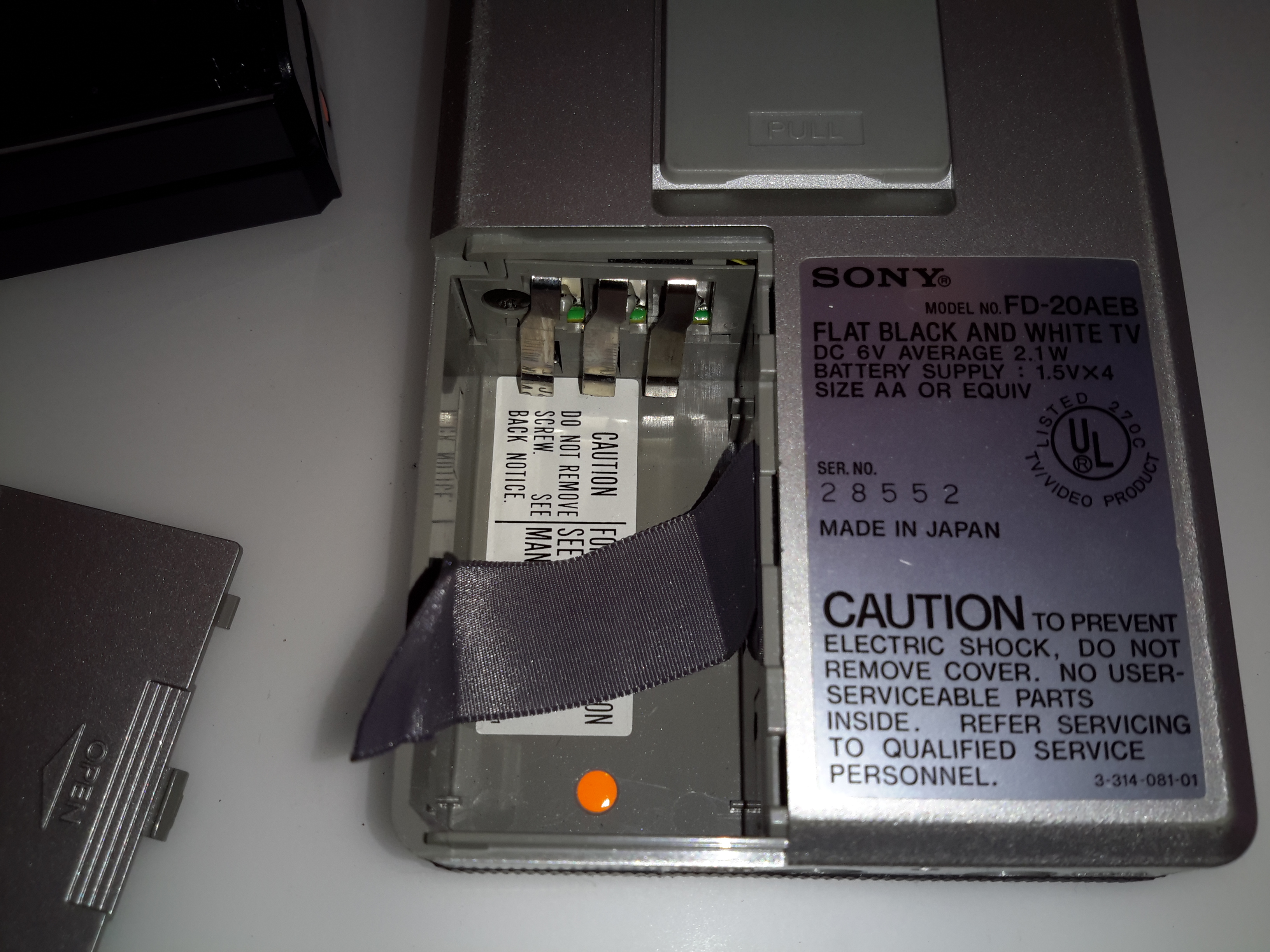
Battery Compartment
The battery holder slots into the back of the TV, there’s also an extra contact that the service manual mentions is for charging, so I assume a rechargeable 6v battery pack was also available.
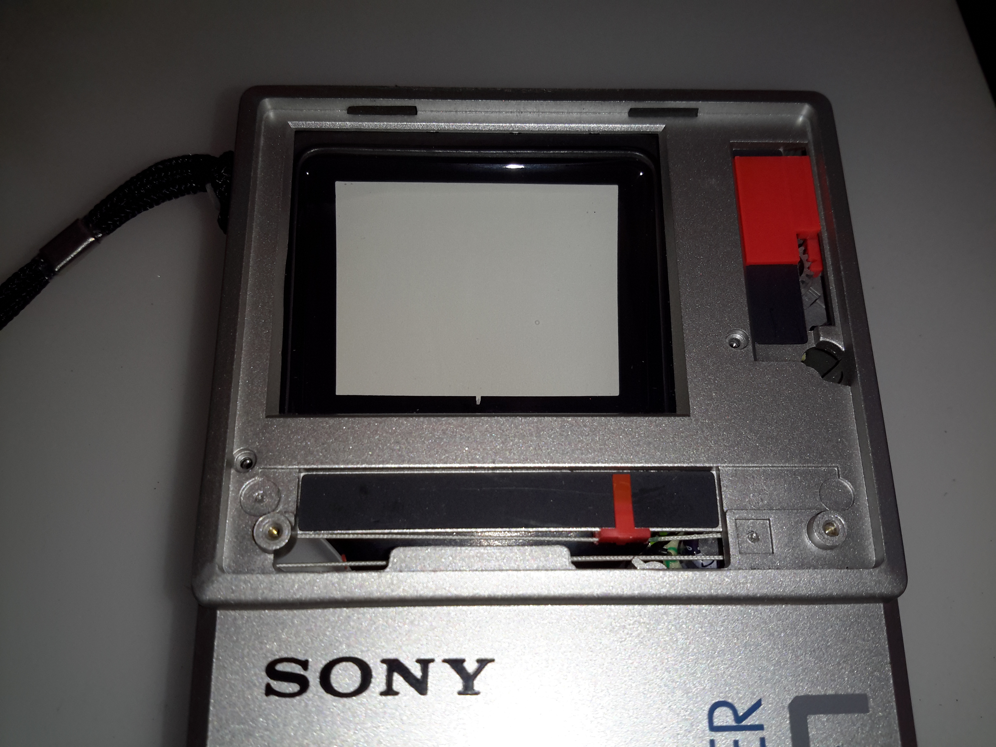
Front Panel Removed
Removing a pair of pin-spanner type screws allows the front glass & screen printed CRT surround to be removed. Not much more under here other than the pair of screws that retain the CRT in the front frame.
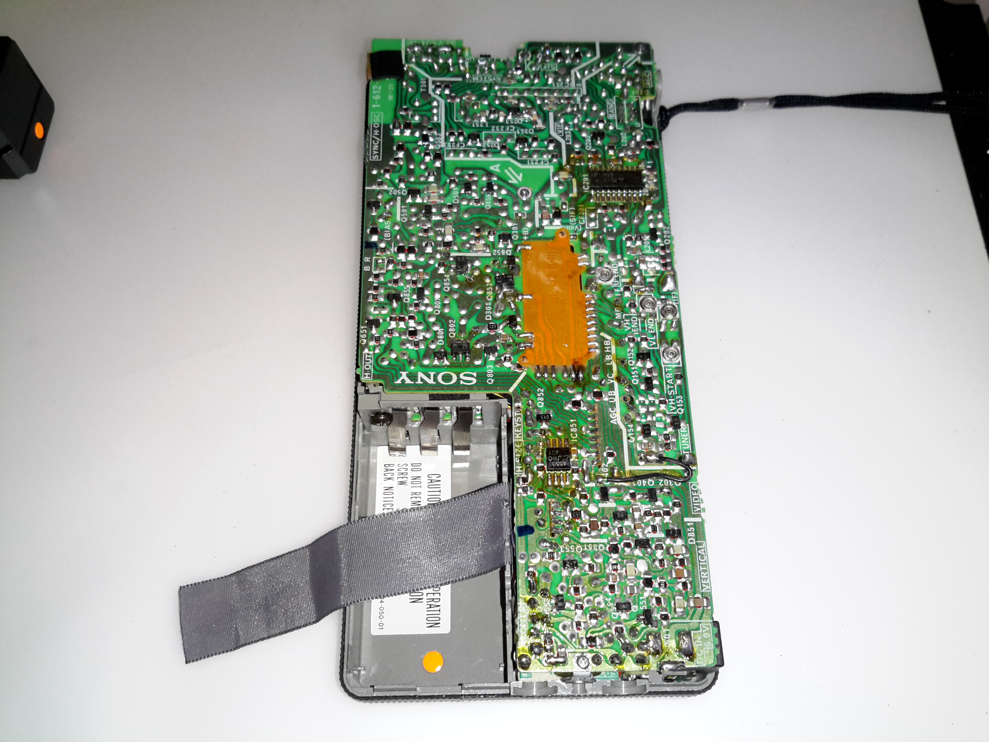
Back Cover Removed
Here’s the back cover removed, after unscrewing some very small screws. As per usual with Sony gear, the electronics is extremely compacted, using many flat flex cables between the various PCBs. The main PCB is visible at the back, this has all the deflection circuitry, RF tuner, Video IF, Audio IF, video amplifier & composite circuitry.
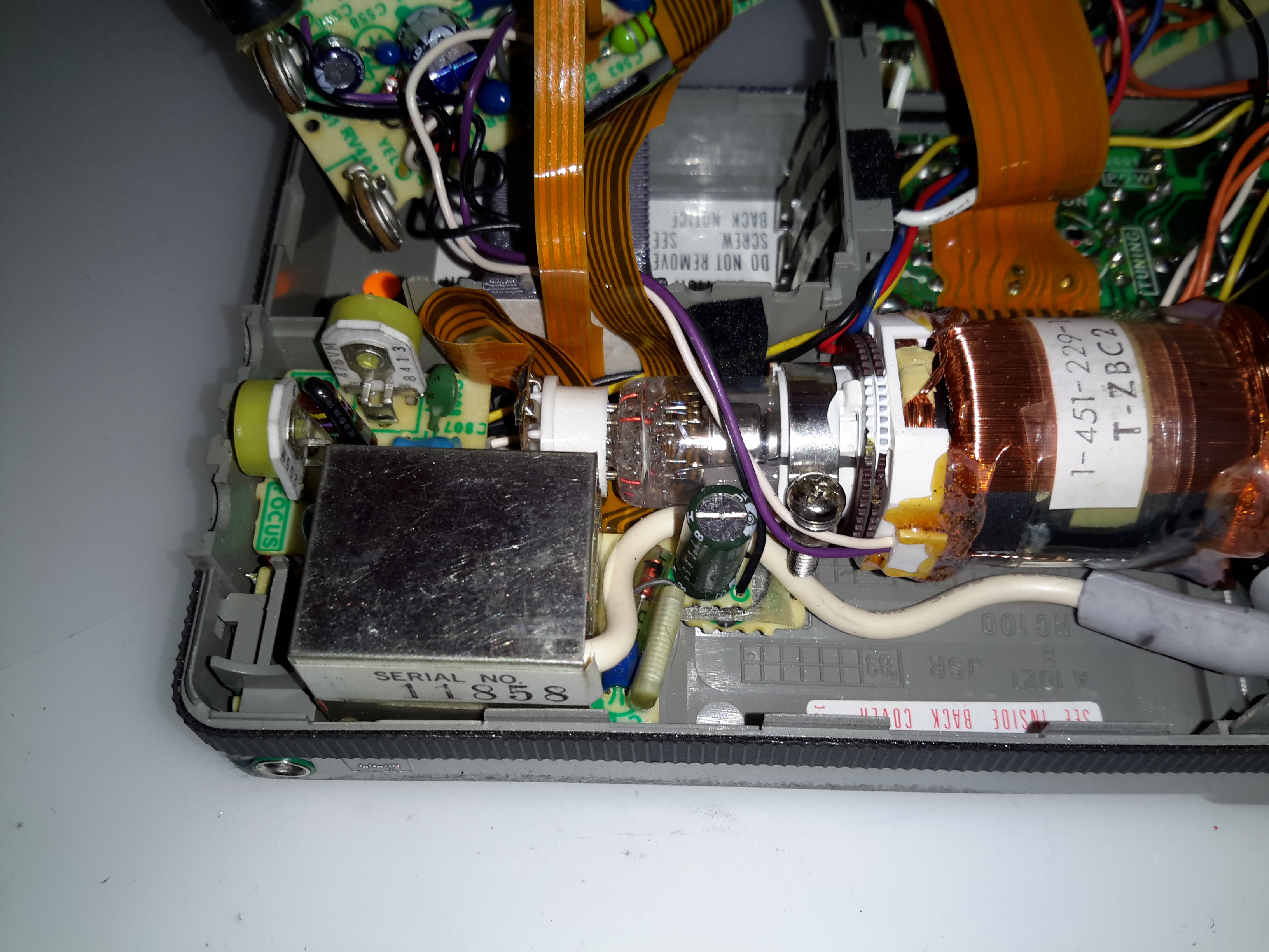
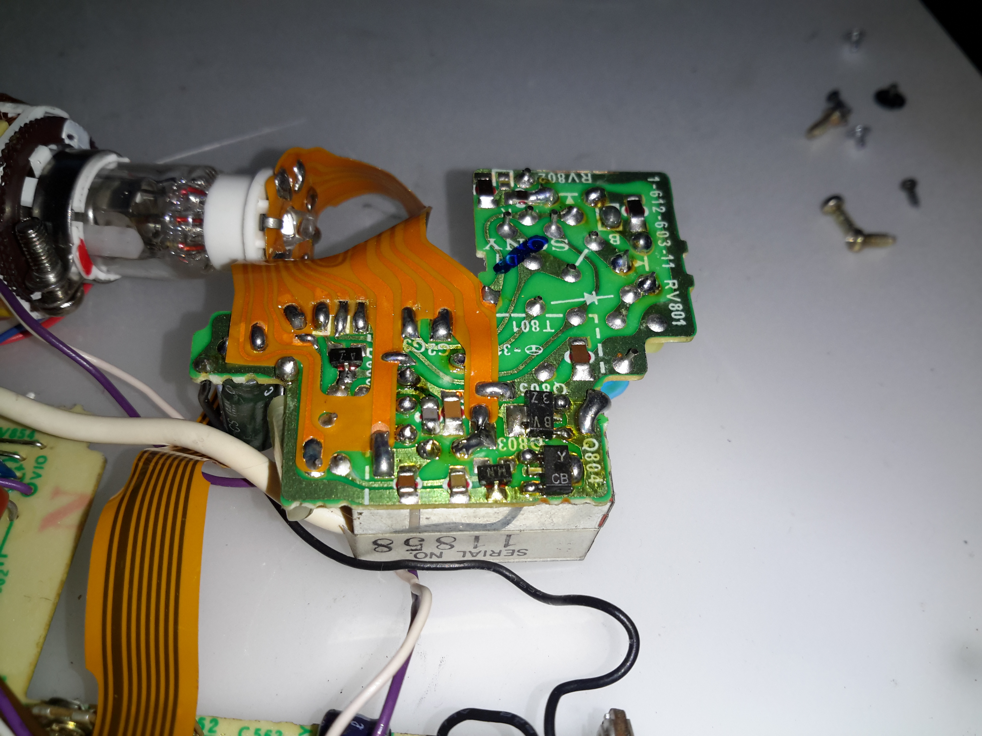
CRT Electron Gun & Flyback Transformer
Lifting up the main board reveals more PCBs – the high voltage section for the CRT with the flyback transformer, focus & brightness controls is on the left. The loudspeaker PCB is below this. The CRT electron gun is tucked in behind the flyback transformer, it’s socket being connected to the rest of the circuitry with a flat flex cable.
CRT Rear
Here’s the back of the CRT, the phosphor screen is on the other side of the curved glass back. These tubes must require some additional deflection complexity, as the geometry will change as the beam scans across the screen. There’s a dynamic focus circuit on the schematics, along with extensive keystone adjustments.
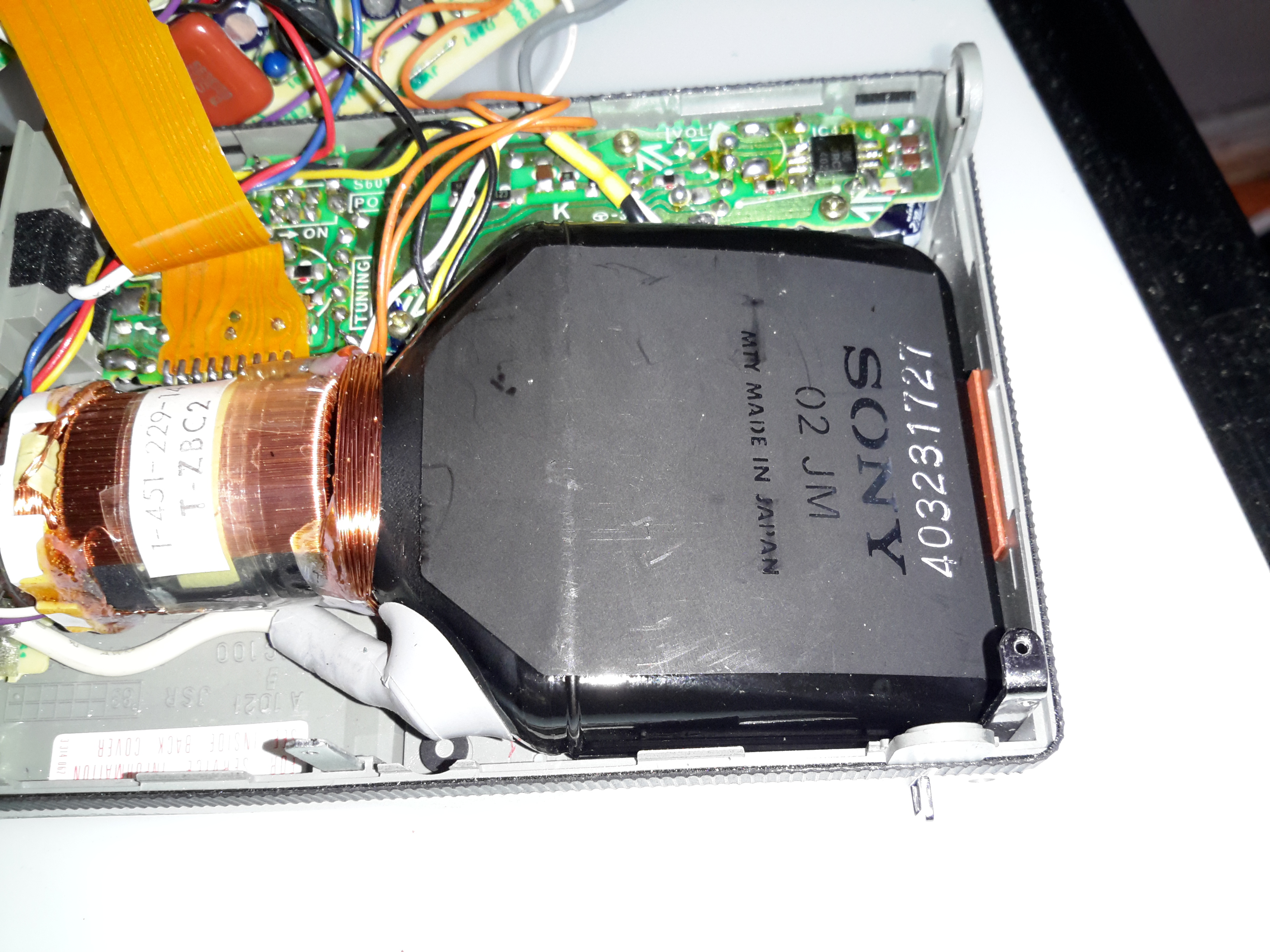
Sony 02-JM Flat CRT
Here’s the tube entirely extracted from the chassis. The EHT connection to the final anode is on the side of the tube bell, the curved phosphor screen is clearly visible. The one thing I can’t find in this CRT is a getter spot, so Sony may have a way of getting a pure enough vacuum that one isn’t required.
I’d expect the vertical deflection waveforms to be vastly different on this kind of CRT, due to the strange screen setup. Not much of a beam movement is required to move the spot from the top to the bottom of the screen.
HV Module
No doubt to keep the isolation gaps large, all the high voltages are kept on a separate small PCB with the flyback transformer. This board generates the voltages for the electron gun filament, focus grid & the bias to set the beam current (brightness) as well.
Bare CRT
Here the deflection yoke has been removed from the CRT, showing the very odd shape better. These tubes are constructed of 3 pieces of glass, the bell with electron gun, back glass with phosphor screen & front viewing window glass. All these components are joined with glass frit.
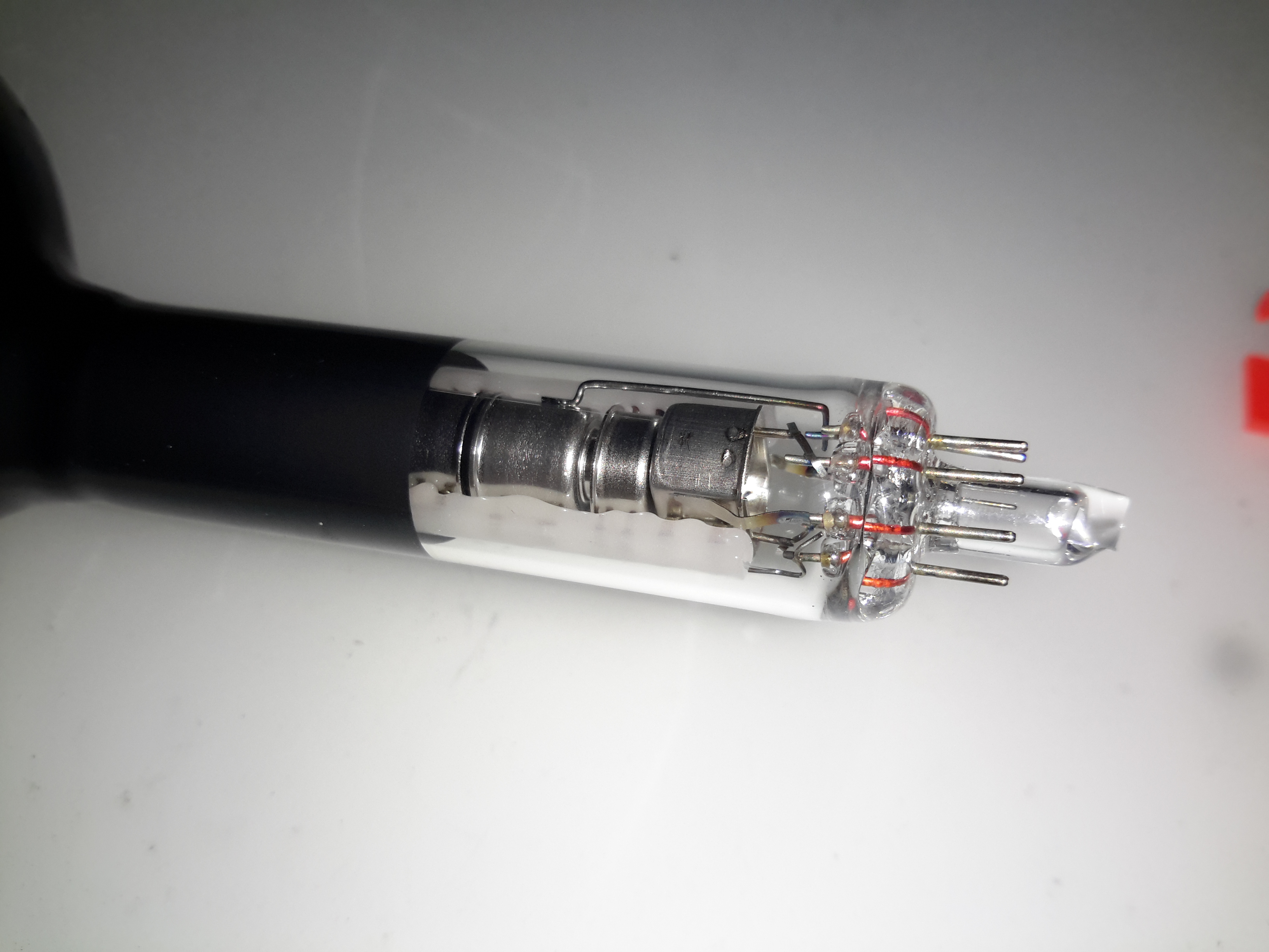
Electron Gun
The electron gun in the neck looks to be pretty much standard, with all the usual electrodes.
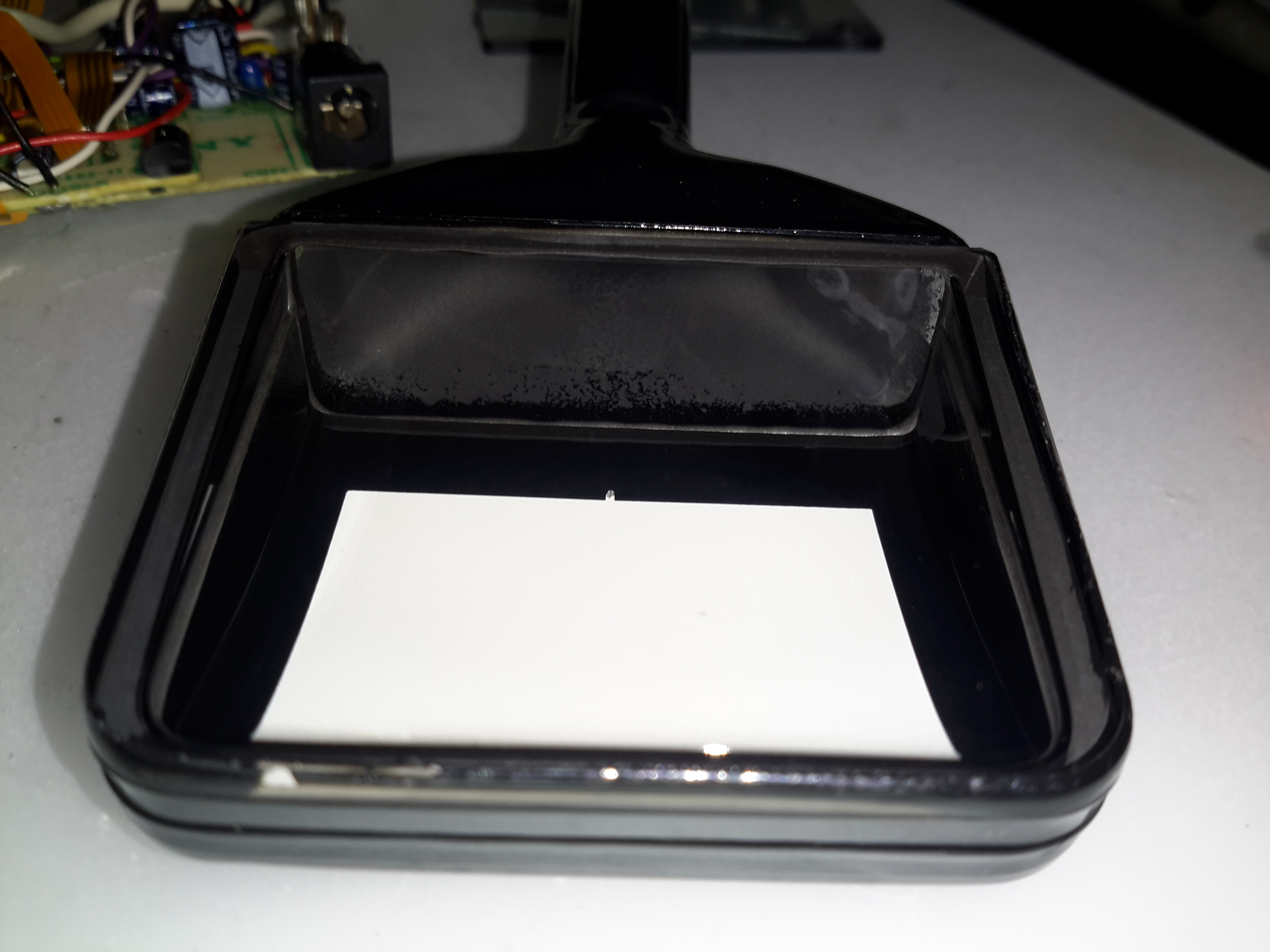
Viewing Window
Here’s a view from the very top of the CRT, the curve in the screen is very obvious here. The electron beam emerges from the bell at the back.
FD-20 Schematic
Here’s the full schematic of the entire TV, I extracted this from a service manual I managed to find online.
More to come on hacking this unit to accept a standard composite video input, from something such as a Raspberry Pi!
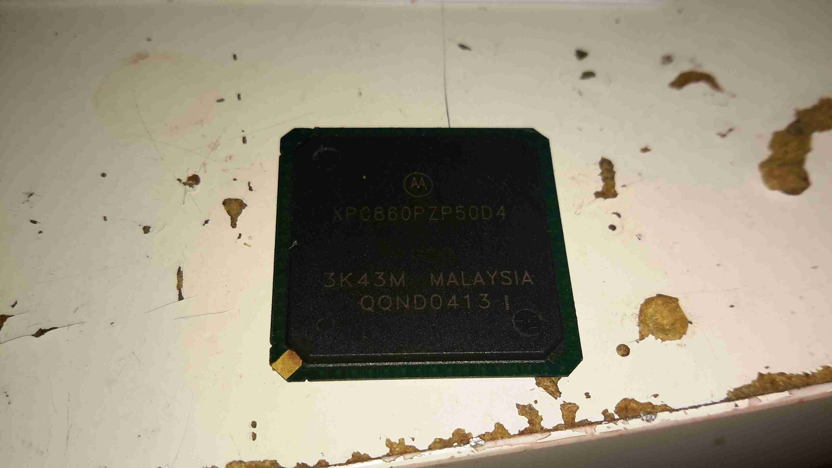
This is a System On Chip from Motorola, designed for network routing applications. This chip contains a hell of a feature set, so I’ll just include an excerpt from the datasheet:
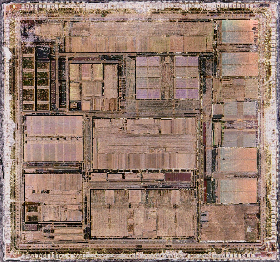
XPC860PZP50D4 Die
Embedded single-issue, 32-bit MPC8xx core (implementing the PowerPC
architecture) with thirty-two 32-bit general-purpose registers (GPRs)
— The core performs branch prediction with conditional prefetch, without
conditional execution
— 4- or 8-Kbyte data cache and 4- or 16-Kbyte instruction cache (see Table 1)
– 16-Kbyte instruction caches are four-way, set-associative with 256 sets;
4-Kbyte instruction caches are two-way, set-associative with 128 sets.
– 8-Kbyte data caches are two-way, set-associative with 256 sets; 4-Kbyte data
caches are two-way, set-associative with 128 sets.
– Cache coherency for both instruction and data caches is maintained on 128-bit
(4-word) cache blocks.
– Caches are physically addressed, implement a least recently used (LRU)
replacement algorithm, and are lockable on a cache block basis.
— Instruction and data caches are two-way, set-associative, physically addressed,
LRU replacement, and lockable on-line granularity.
— MMUs with 32-entry TLB, fully associative instruction, and data TLBs
— MMUs support multiple page sizes of 4, 16, and 512 Kbytes, and 8 Mbytes; 16
virtual address spaces and 16 protection groups
— Advanced on-chip-emulation debug mode
Up to 32-bit data bus (dynamic bus sizing for 8, 16, and 32 bits)
32 address lines
Operates at up to 80 MHz
Memory controller (eight banks)
— Contains complete dynamic RAM (DRAM) controller
— Each bank can be a chip select or RAS to support a DRAM bank
— Up to 15 wait states programmable per memory bank
— Glueless interface to DRAM, SIMMS, SRAM, EPROM, Flash EPROM, and
other memory devices.
— DRAM controller programmable to support most size and speed memory
interfaces
— Four CAS lines, four WE lines, one OE line
— Boot chip-select available at reset (options for 8-, 16-, or 32-bit memory)
— Variable block sizes (32 Kbyte to 256 Mbyte)
— Selectable write protection
— On-chip bus arbitration logic
General-purpose timers
— Four 16-bit timers or two 32-bit timers
— Gate mode can enable/disable counting
— Interrupt can be masked on reference match and event capture
System integration unit (SIU)
— Bus monitor
— Software watchdog
— Periodic interrupt timer (PIT)
— Low-power stop mode
— Clock synthesizer
— Decrementer, time base, and real-time clock (RTC) from the PowerPC
architecture
— Reset controller
— IEEE 1149.1 test access port (JTAG)
Interrupts
— Seven external interrupt request (IRQ) lines
— 12 port pins with interrupt capability
— 23 internal interrupt sources
— Programmable priority between SCCs
— Programmable highest priority request
10/100 Mbps Ethernet support, fully compliant with the IEEE 802.3u Standard (not
available when using ATM over UTOPIA interface)
ATM support compliant with ATM forum UNI 4.0 specification
— Cell processing up to 50–70 Mbps at 50-MHz system clock
— Cell multiplexing/demultiplexing
— Support of AAL5 and AAL0 protocols on a per-VC basis. AAL0 support enables
OAM and software implementation of other protocols).
— ATM pace control (APC) scheduler, providing direct support for constant bit rate
(CBR) and unspecified bit rate (UBR) and providing control mechanisms
enabling software support of available bit rate (ABR)
— Physical interface support for UTOPIA (10/100-Mbps is not supported with this
interface) and byte-aligned serial (for example, T1/E1/ADSL)
— UTOPIA-mode ATM supports level-1 master with cell-level handshake,
multi-PHY (up to 4 physical layer devices), connection to 25-, 51-, or 155-Mbps
framers, and UTOPIA/system clock ratios of 1/2 or 1/3.
— Serial-mode ATM connection supports transmission convergence (TC) function
for T1/E1/ADSL lines; cell delineation; cell payload scrambling/descrambling;
automatic idle/unassigned cell insertion/stripping; header error control (HEC)
generation, checking, and statistics.
Communications processor module (CPM)
— RISC communications processor (CP)
— Communication-specific commands (for example, GRACEFUL STOP TRANSMIT ,
ENTER HUNT MODE , and RESTART TRANSMIT )
— Supports continuous mode transmission and reception on all serial channels
— Up to 8Kbytes of dual-port RAM
— 16 serial DMA (SDMA) channels
— Three parallel I/O registers with open-drain capability
Four baud-rate generators (BRGs)
— Independent (can be connected to any SCC or SMC)
— Allow changes during operation
— Autobaud support option
Four serial communications controllers (SCCs)
— Ethernet/IEEE 802.3 optional on SCC1–4, supporting full 10-Mbps operation
(available only on specially programmed devices).
— HDLC/SDLC (all channels supported at 2 Mbps)
— HDLC bus (implements an HDLC-based local area network (LAN))
— Asynchronous HDLC to support PPP (point-to-point protocol)
— AppleTalk
— Universal asynchronous receiver transmitter (UART)
— Synchronous UART
— Serial infrared (IrDA)
— Binary synchronous communication (BISYNC)
— Totally transparent (bit streams)
— Totally transparent (frame based with optional cyclic redundancy check (CRC))
Two SMCs (serial management channels)
— UART
— Transparent
— General circuit interface (GCI) controller
— Can be connected to the time-division multiplexed (TDM) channels
One SPI (serial peripheral interface)
— Supports master and slave modes
— Supports multimaster operation on the same bus
One I 2 C (inter-integrated circuit) port
— Supports master and slave modes
— Multiple-master environment support
Time-slot assigner (TSA)
— Allows SCCs and SMCs to run in multiplexed and/or non-multiplexed operation
— Supports T1, CEPT, PCM highway, ISDN basic rate, ISDN primary rate, user
defined
— 1- or 8-bit resolution
— Allows independent transmit and receive routing, frame synchronization,
clocking
— Allows dynamic changes
— Can be internally connected to six serial channels (four SCCs and two SMCs)
Parallel interface port (PIP)
— Centronics interface support
— Supports fast connection between compatible ports on the MPC860 or the
MC68360
PCMCIA interface
— Master (socket) interface, release 2.1 compliant
— Supports two independent PCMCIA sockets
— Eight memory or I/O windows supported
Low power support
— Full on—all units fully powered
— Doze—core functional units disabled, except time base decrementer, PLL,
memory controller, RTC, and CPM in low-power standby
— Sleep—all units disabled, except RTC and PIT, PLL active for fast wake up
— Deep sleep—all units disabled including PLL, except RTC and PIT
— Power down mode— all units powered down, except PLL, RTC, PIT, time base,
and decrementer
Debug interface
— Eight comparators: four operate on instruction address, two operate on data
address, and two operate on data
— Supports conditions: = ≠ < >
— Each watchpoint can generate a break-point internally
3.3 V operation with 5-V TTL compatibility except EXTAL and EXTCLK
357-pin ball grid array (BGA) package
As I’ve been posting some photos of decapped ICs lately, I thought I’d share the process I use personally for those that might want to give it a go 😉
The usual method for removing the epoxy package from the silicon is to use hot, concentrated Nitric Acid. Besides the obvious risks of having hot acids around, the decomposition products of the acid, namely NO² (Nitrogen Dioxide) & NO (Nitrogen Oxide), are toxic and corrosive. So until I can get the required fume hood together to make sure I’m not going to corrode the place away, I’ll leave this process to proper labs ;).
The method I use is heat based, using a Propane torch to destroy the epoxy package, without damaging the Silicon die too much.
TMS57002 Audio DSP
I start off, obviously, with a desoldered IC, the one above an old audio DSP from TI. I usually desolder en-masse for this with a heat gun, stripping the entire board in one go.
FLAMES!
Next is to apply the torch to the IC. A bit of practice is required here to get the heat level & time exactly right, overheating will cause the die to oxidize & blacken or residual epoxy to stick to the surface.
I usually apply the torch until the package just about stops emitting it’s own yellow flames, meaning the epoxy is almost completely burned away. I also keep the torch flame away from the centre of the IC, where the die is located.
Breathing the fumes from this process isn’t recommended, no doubt besides the obvious soot, the burning plastic will be emitting many compounds not brilliant for Human health!
Once the IC is roasted to taste, it’s quenched in cold water for a few seconds. Sometimes this causes such a high thermal shock that the leadframe cracks off the epoxy around the die perfectly.
All Your Die Belong To Us
Now that the epoxy has been destroyed, it breaks apart easily, and is picked away until I uncover the die itself. (It’s the silver bit in the middle of the left half). The heat from the torch usually destroys the Silver epoxy holding the die to the leadframe, and can be removed easily from the remaining package.
Decapped
BGA packages are usually the easiest to decap, flip-chip packages are a total pain due to the solder balls being on the front side of the die, I haven’t managed to get a good result here yet, I’ll probably need to chemically remove the first layer of the die to get at the interesting bits 😉
Slide
Once the die has been rinsed in clean water & inspected, it’s mounted on a glass microscope slide with a small spot of Cyanoacrylate glue to make handling easier.
Some dies require some cleaning after decapping, for this I use 99% Isopropanol & 99% Acetone, on the end of a cotton bud. Any residual epoxy flakes or oxide stuck to the die can be relatively easily removed with a fingernail – turns out fingernails are hard enough to remove the contamination, but not hard enough to damage the die features.
Once cleaning is complete, the slide is marked with the die identification, and the photographing can begin.
Microscope Mods
I had bought a cheap eBay USB microscope to get started, as I can’t currently afford a proper metallurgical microscope, but I found the resolution of 640×480 very poor. Some modification was required!
Modified Microscope
I’ve removed the original sensor board from the back of the optics assembly & attached a Raspberry Pi camera board. The ring that held the original sensor board has been cut down to a minimum, as the Pi camera PCB is slightly too big to fit inside.
The stock ring of LEDs is run direct from the 3.3v power rail on the camera, through a 4.7Ω resistor, for ~80mA. I also added a 1000µF capacitor across the 3.3v supply to compensate a bit for the long cable – when a frame is captured the power draw of the camera increases & causes a bit of voltage drop.
The stock lens was removed from the Pi camera module by careful use of a razor blade – being too rough here *WILL* damage the sensor die or the gold bond wires, which are very close to the edge of the lens housing, so be gentle!
Mounting Base
The existing mount for the microscope is pretty poor, so I’ve used a couple of surplus ceramic ring magnets as a better base, this also gives me the option of raising or lowering the base by adding or removing magnets.
To get more length between the Pi & the camera, I bought a 1-meter cable extension kit from Pi-Cables over at eBay, cables this long *definitely* require shielding in my space, which is a pretty aggressive RF environment, or interference appears on the display. Not surprising considering the high data rates the cable carries.
The FFC interface is hot-glued to the back of the microscope mount for stability, for handheld use the FFC is pretty flexible & doesn’t apply any force to the scope.
Die Photography
Since I modified the scope with a Raspberry Pi camera module, everything is done through the Pi itself, and the raspistill command.
Pi LCD
The command I’m currently using to capture the images is:
raspistill -ex auto -awb auto -mm matrix -br 62 -q 100 -vf -hf -f -t 0 -k -v -o CHIPNAME_%03d.jpg
This command waits between each frame for the ENTER key to be pressed, allowing me to position the scope between shots. Pi control & file transfer is done via SSH, while I use the 7″ touch LCD as a viewfinder.
The direct overhead illumination provided by the stock ring of LEDs isn’t ideal for some die shots, so I’m planning on fitting some off-centre LEDs to improve the resulting images.
Image Processing
Obviously I can’t get an ultra-high resolution image with a single shot, due to the focal length, so I have to take many shots (30-180 per die), and stitch them together into a single image.
For this I use Hugin, an open-source panorama photo stitching package.
Hugin
Here’s Hugin with the photos loaded in from the Raspberry Pi. To start with I use Hugin’s built in CPFind to process the images for control points. The trick with getting good control points is making sure the images have a high level of overlap, between 50-80%, this way the software doesn’t get confused & stick the images together incorrectly.
Optimiser
After the control points are generated, which for a large number of high resolution images can take some time, I run the optimiser with only Yaw & Pitch selected for all images.
Optimising
If all goes well, the resulting optimisation will get the distance between control points to less than 0.3 pixels.
Panorama Preview
After the control points & optimisation is done, the resulting image can be previewed before generation.
Texas Instruments TMS67002
After all the image processing, the resulting die image should look something like the above, with no noticeable gaps.
Here’s some teardown photos of an old De La Rue coin counter, used in businesses for rapid counting of change into large bags.
Mechanism
An overview of the whole mechanical system of the counter. Coins are loaded into the drum at the rear of the machine, which sorts them into a row for the rubber belt to pick up & run through the counter. The coin type to be sorted is selected by turning the control knobs on the right.
The control knobs adjust the width & height of the coin channel so only the correct sized coins will be counted.
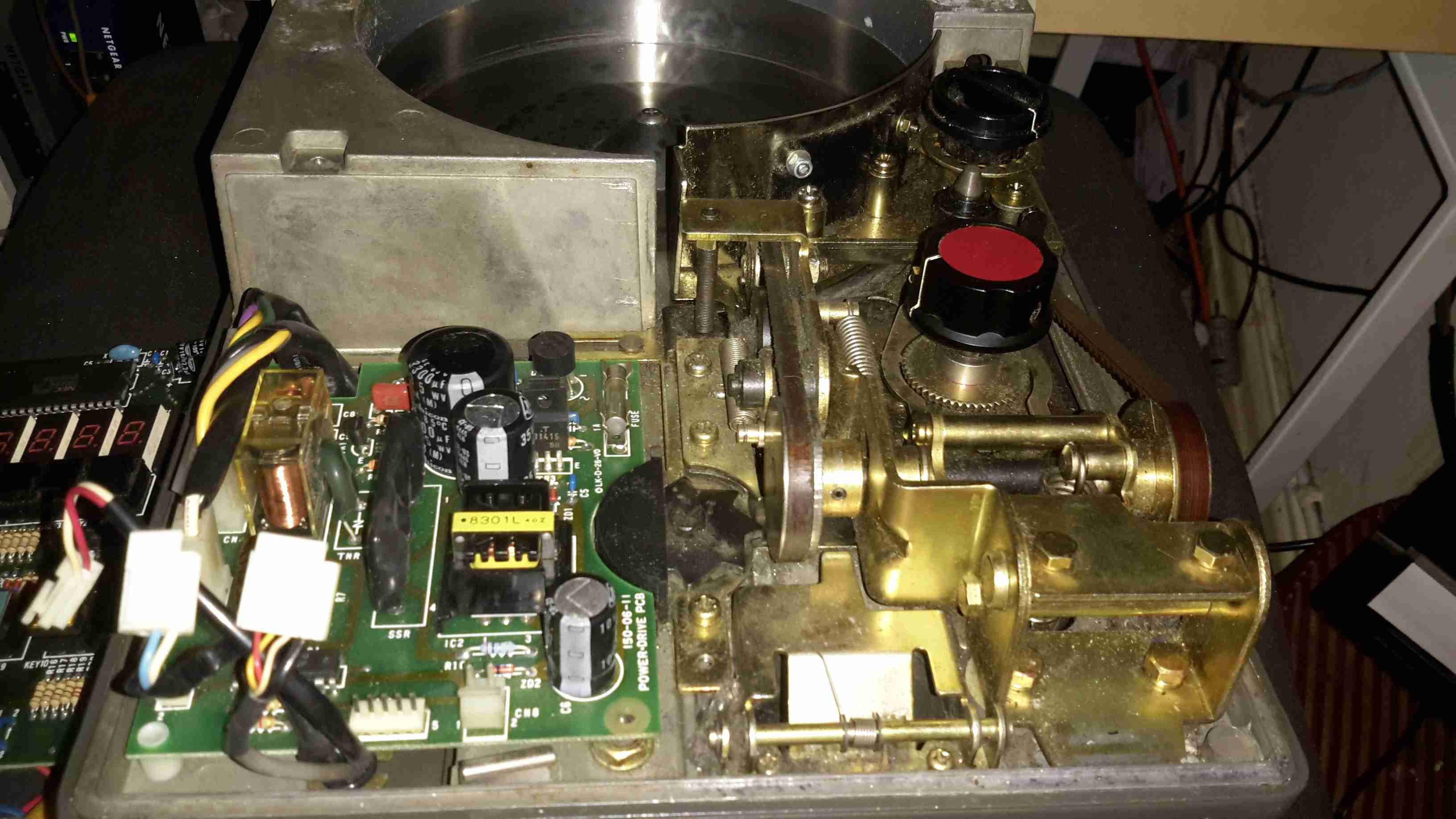
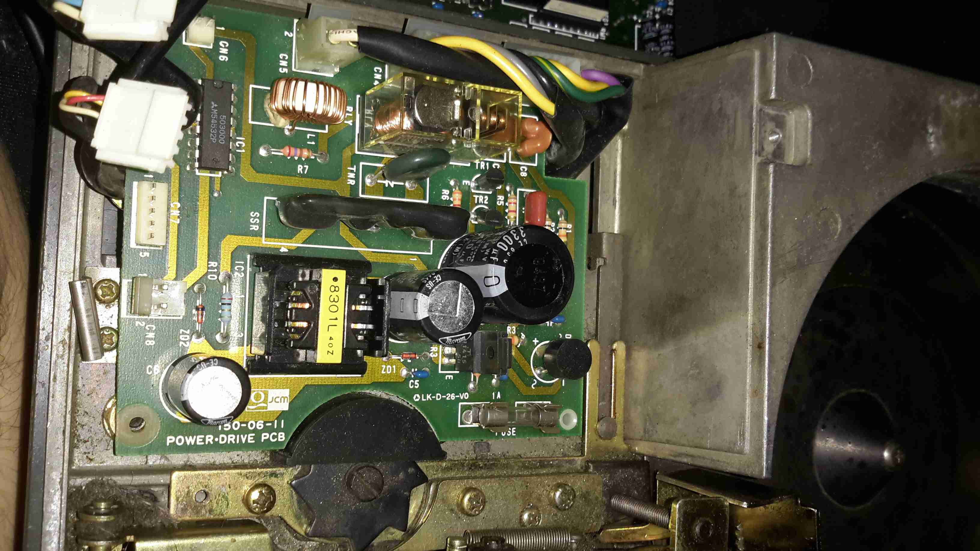
PSU & Switching
The counter is driven by a basic AC induction motor, the motor power relay & reversing relay is on this PCB, along with the 5v switching supply for the main CPU board.
The SMPS on this board looks like a standard mains unit, but it’s got one big difference. Under the frame next to the main motor is a relatively large transformer, with a 35v output. This AC is fed into the SMPS section of the PSU board to be converted to 5v DC for the logic.
I’m not sure why it’s been done this way, and have never seen anything similar before.
The edge of the coin channel can be seen here, the black star wheel rotates when a coin passes & registers the count.
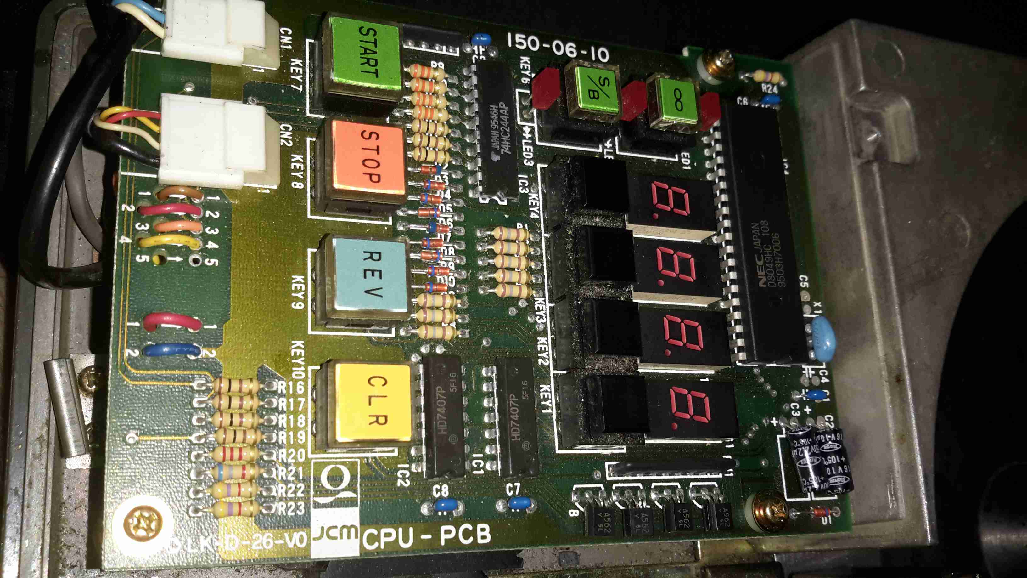
Controller PCB
Here’s the main controller PCB, IC date codes put the unit to about 1995. The main CPU is a NEC UPD8049HC 8-bit micro, no flash or EEPROM on this old CPU, simply mask ROM. Coin readout is done on the 4 7-segment LED displays. Not much to this counter, it’s both electronically & mechanically simple.
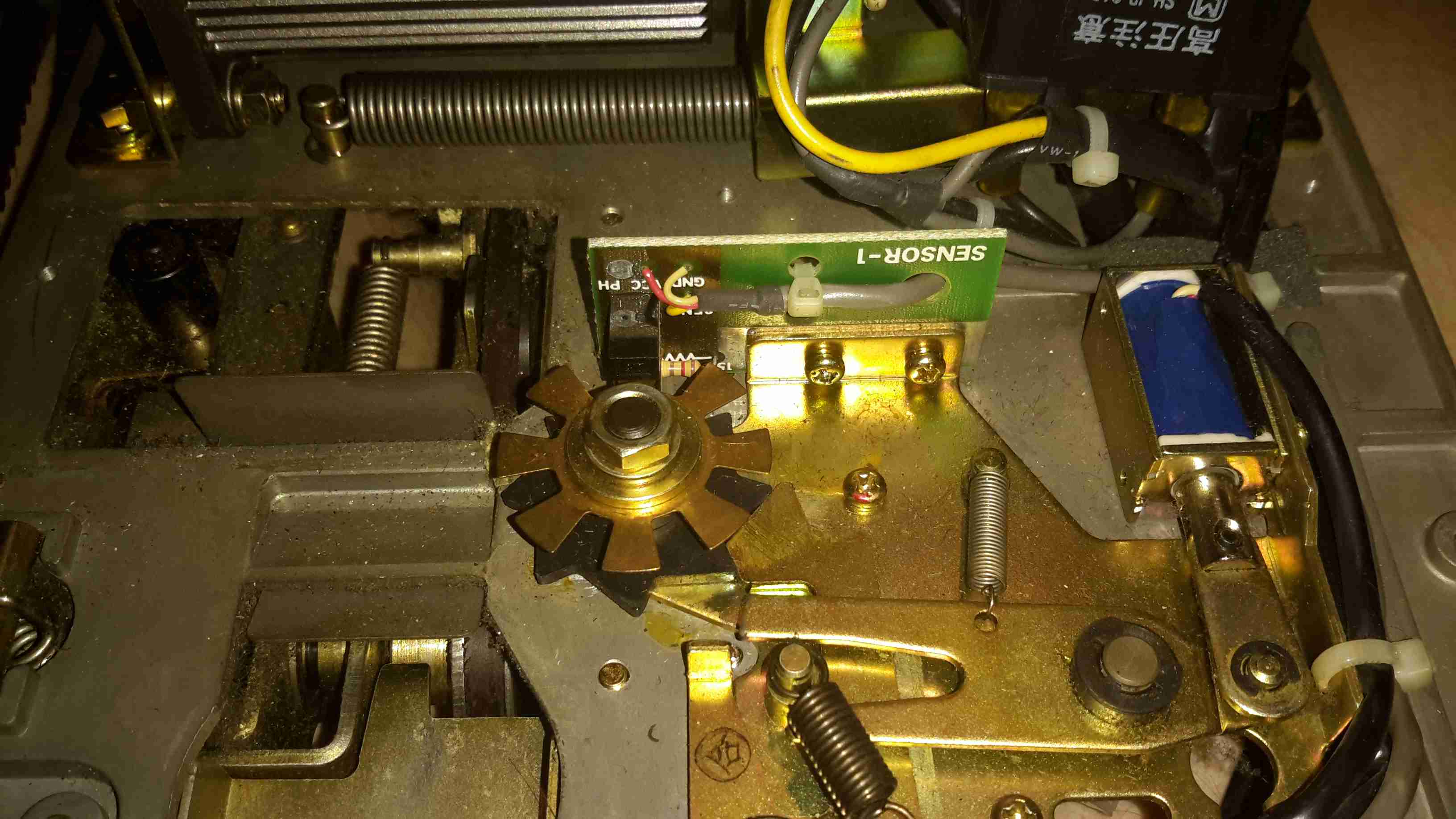
Counter Sensor
Coin counting is done by the star wheel mentioned above, which drives the interrupter disc on this photo-gate. The solenoid locks the counter shaft to prevent over or under counting when a set number of coins is to be counted.
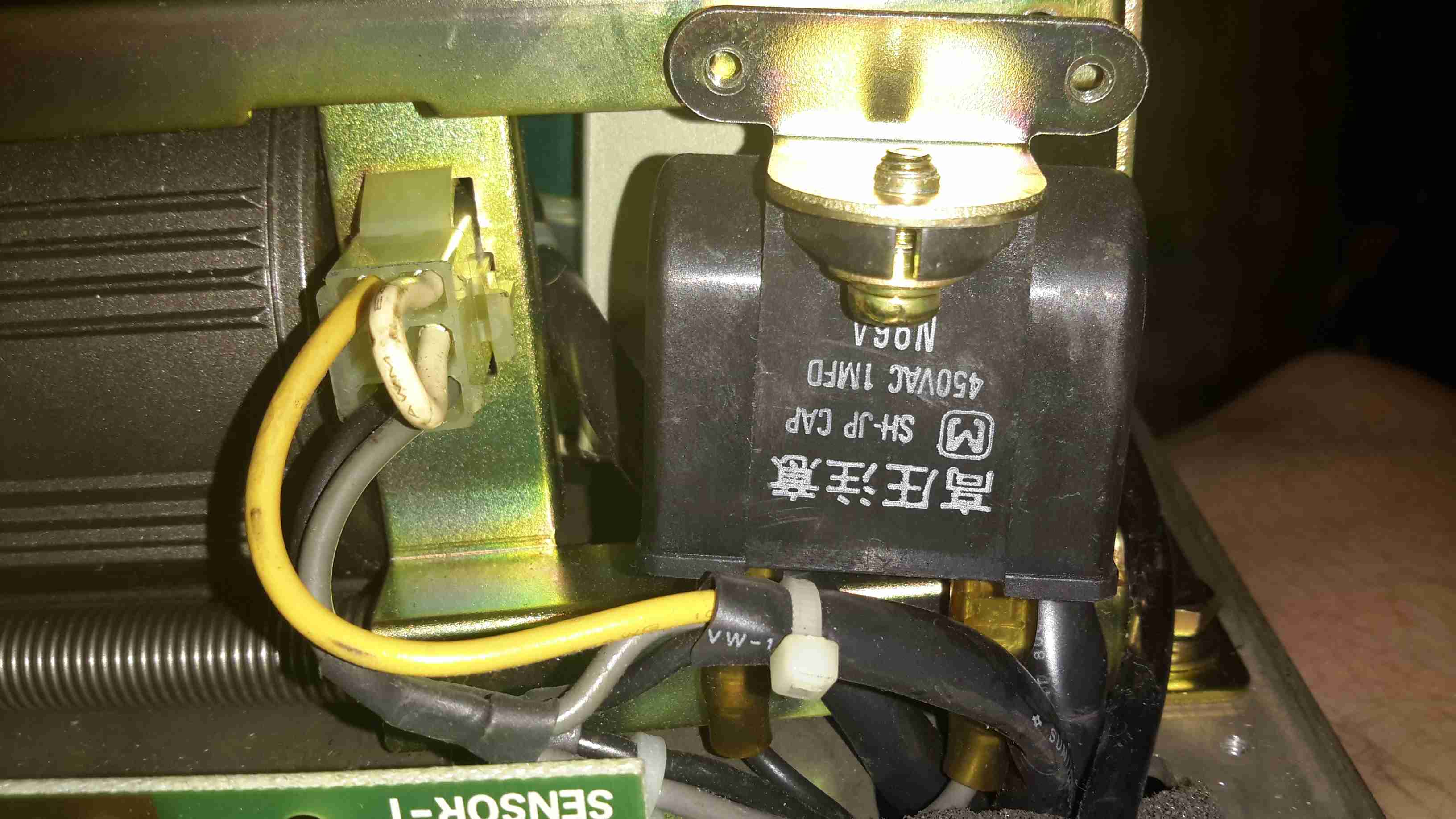
Motor Run Capacitor
Under the frame, here on the left is the small induction motor, only 6W, 4-pole. The run cap for the motor is in the centre, and the 35v transformer is just visible behind it.
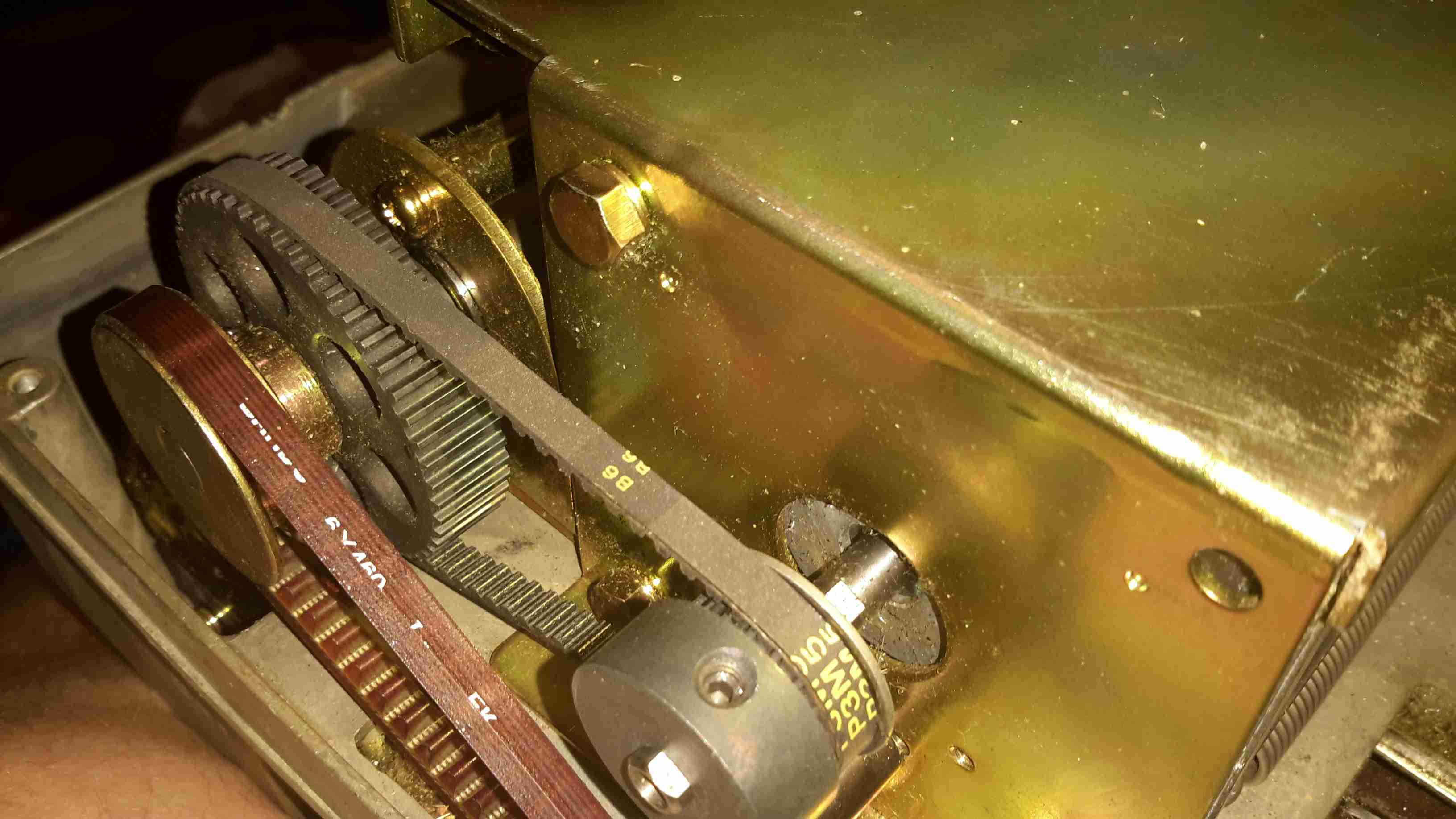
Main Motor Drive
Main drive to the coin sorting mech is through rubber belts, and bevel gears drive the coin drum.
I go camping on a regular basis here in the UK, and often even in summer it’s horribly cold at night in a field somewhere in the middle of Leicestershire. This doesn’t go too well with my severe aversion to being cold.
For the past several years I’ve used a Tilley lamp for some heat & light while at festivals & general camping, but it’s heat output is less than stellar when used in a 6-man tent.
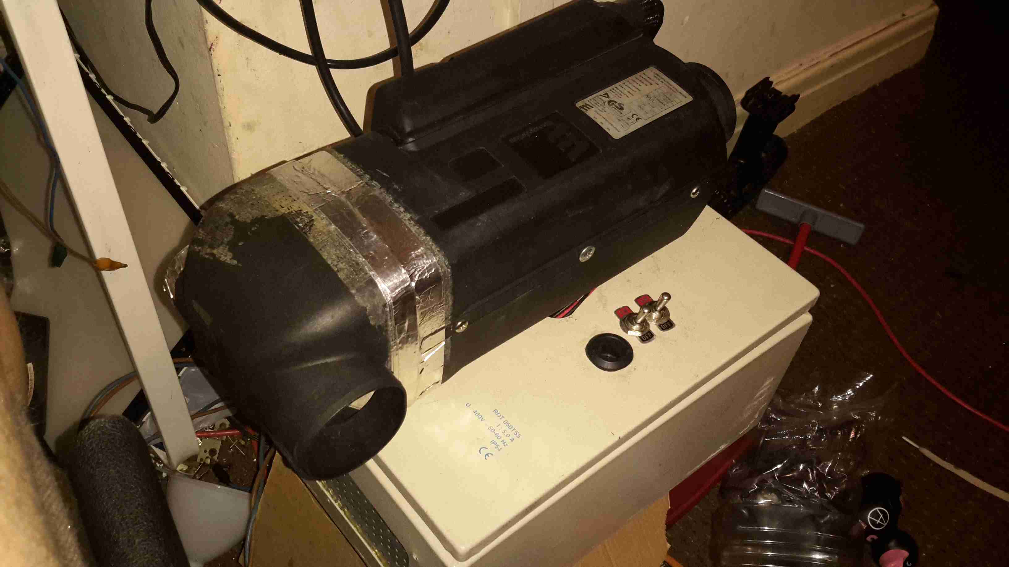
An Eberspacher diesel heater was what was required for the job. Above is the unit as it’s built at the moment – I’ve used an old D1LCC 1.8kW heater that was recently decommissioned from nb Tanya Louise, as it’s getting a bit funny about what kind of fuel it’ll run on in it’s old age. It’ll work perfectly well on kerosene though – a fuel I already take with me camping for the Tilley.
It’s mounted on a base box, which is a repurposed steel electrical junction box that saw a previous life containing a 3-phase fan motor controller.
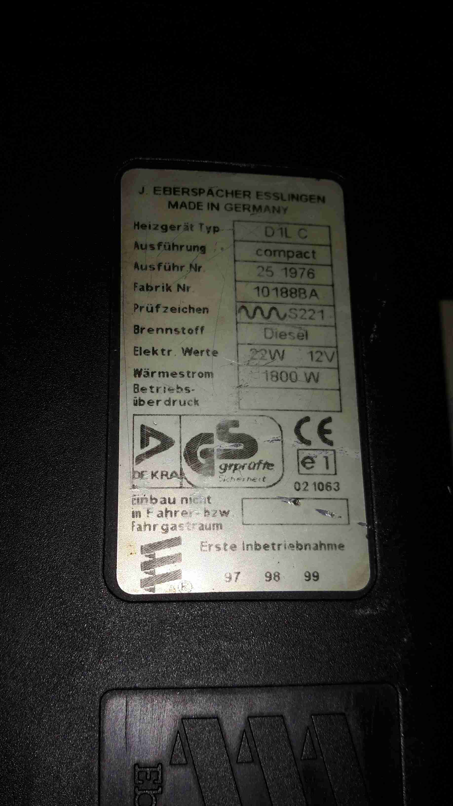
Data Plate
Here’s the info on the heater unit itself. Drawing 22W of power at 12v I’ll be getting 1.8kW of heat output – sounds good to me.
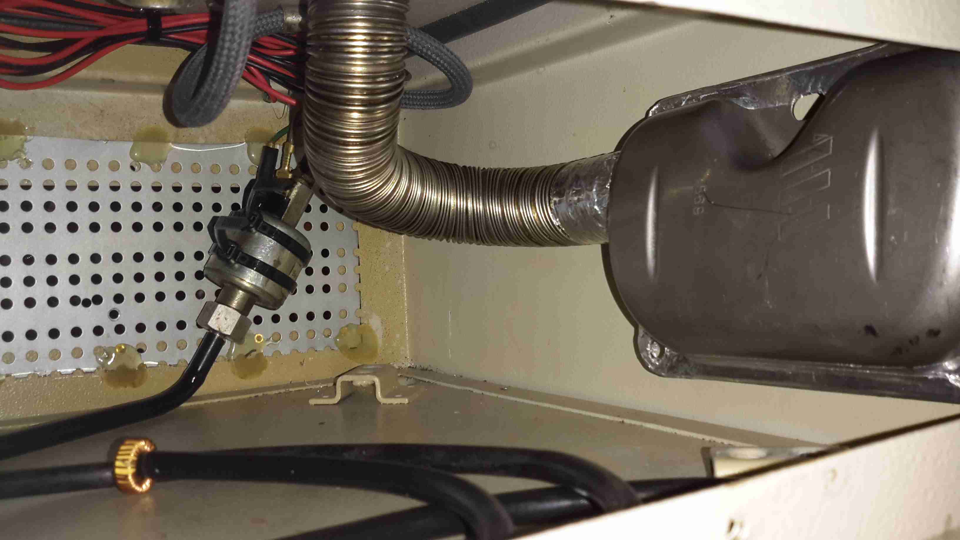
Box Internals
Here’s a view into the base box before the circulation fans were fitted, in early prototype stage. I used a small toroid as a clunk on the end of the rubber fuel line 😉
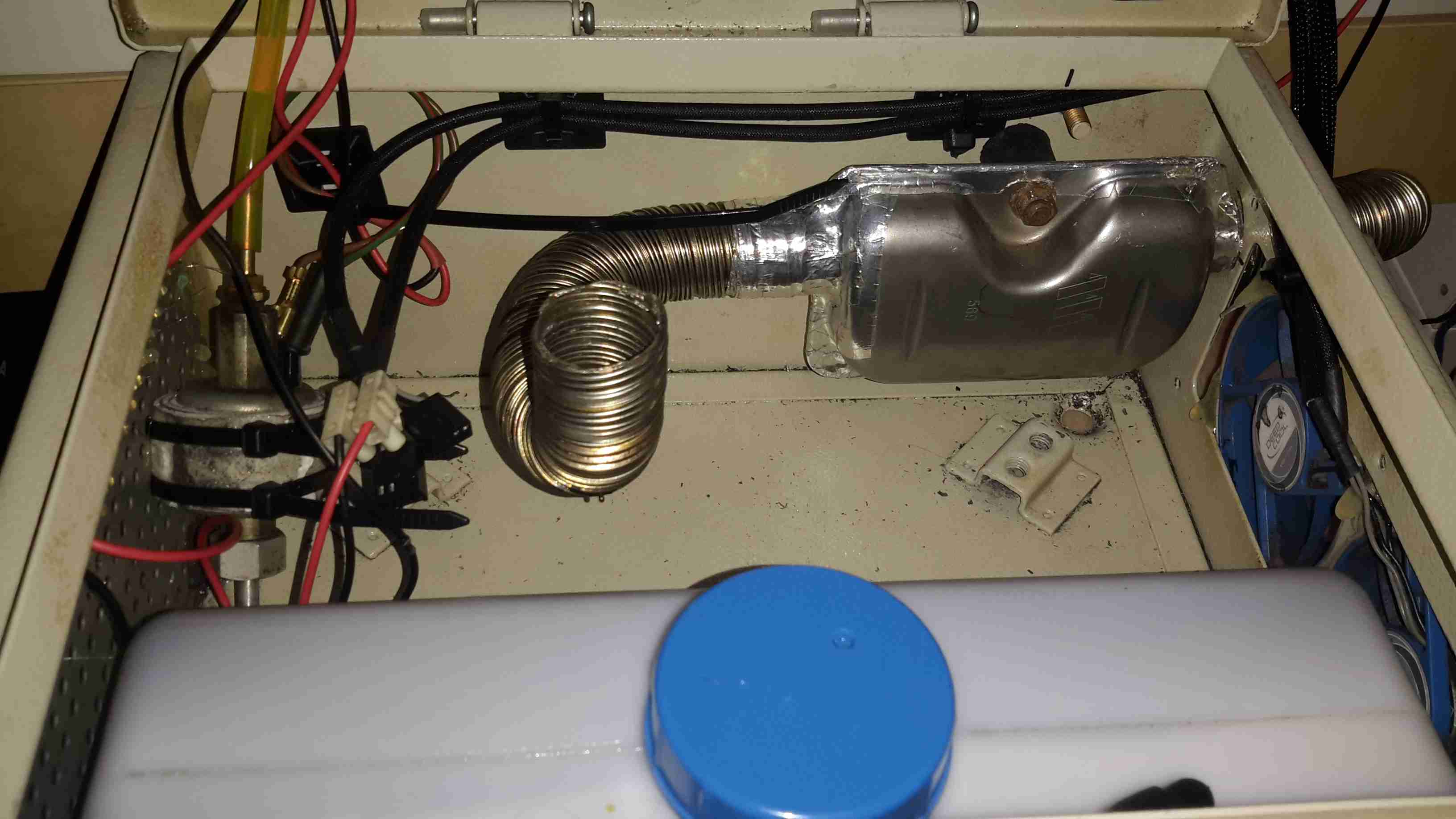
Support Components
After a few bits from the Great eBay arrived, here’s the internals of the base unit at present. The fuel tank is a repurposed 2L fridge water container – made of tough HDPE so it’s fuel resistant.
The fuel pump is mounted on the left side next to the tank – having been wrapped in some foam to deaden the continual ticking noise it creates. The exhaust & it’s silencer are mounted at the rear, the silencer being retained by a surplus rubber shock mount. Luckily the exhaust systems on these heaters don’t get particularly hot, so the rubber doesn’t melt.
The exhaust outlet is routed through the frame, to be attached to an external hose. I don’t want combustion gases in the tent with me!
Standard Eberspacher silencers also aren’t gas-tight from the factory – they’re designed to be used in the open on the underframe of a vehicle, so I’ve covered all the seams in aluminium tape to make the system airtight.
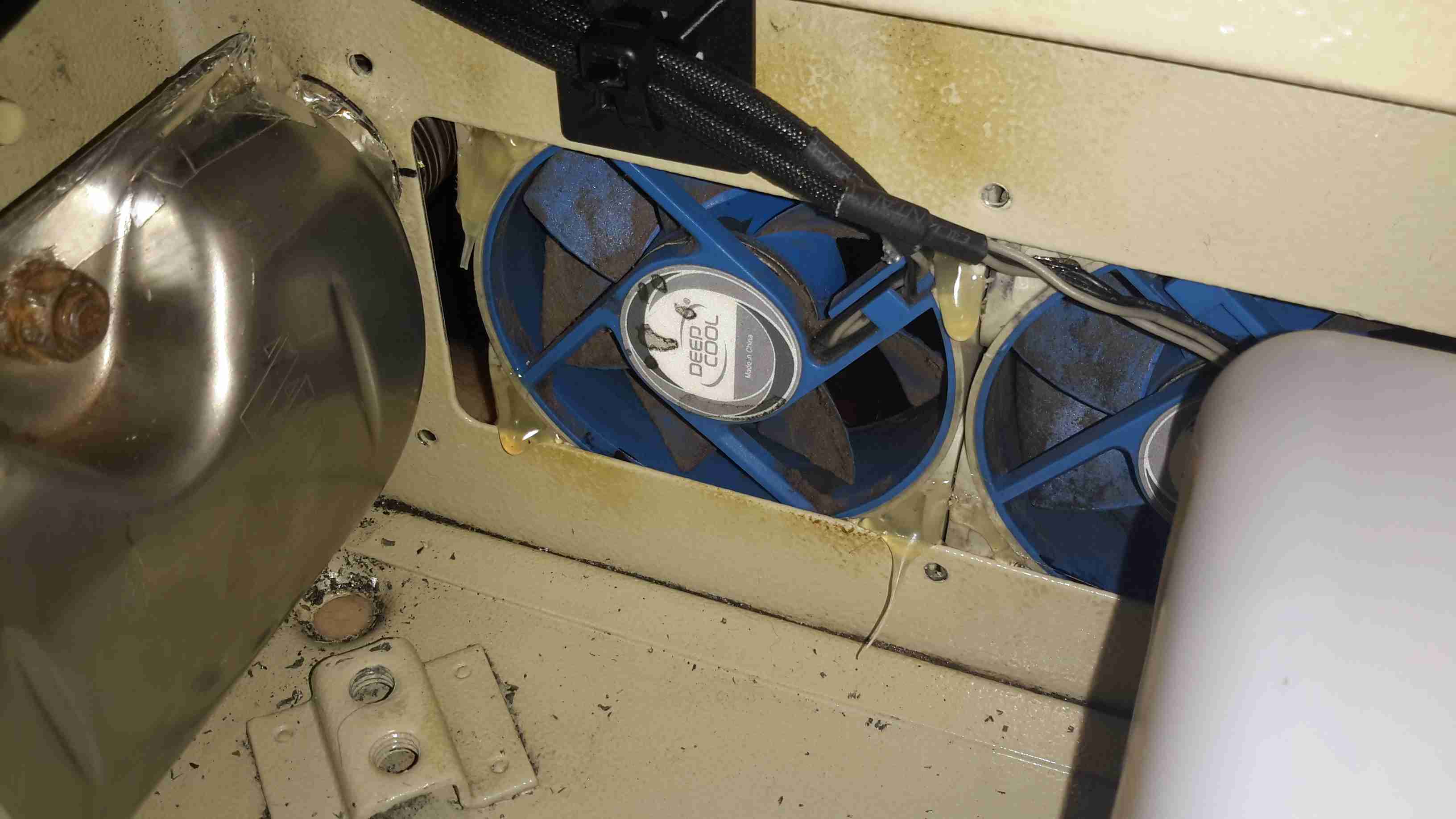
Ventilation
To make sure that the support components don’t get overheated with the exhaust being in such close proximity, and to pull a little more heat out of the system, a pair of slow-running 80mm fans has been fitted to the end of the box. These blow enough air through to give a nice warm breeze from the vents on the other end of the base.
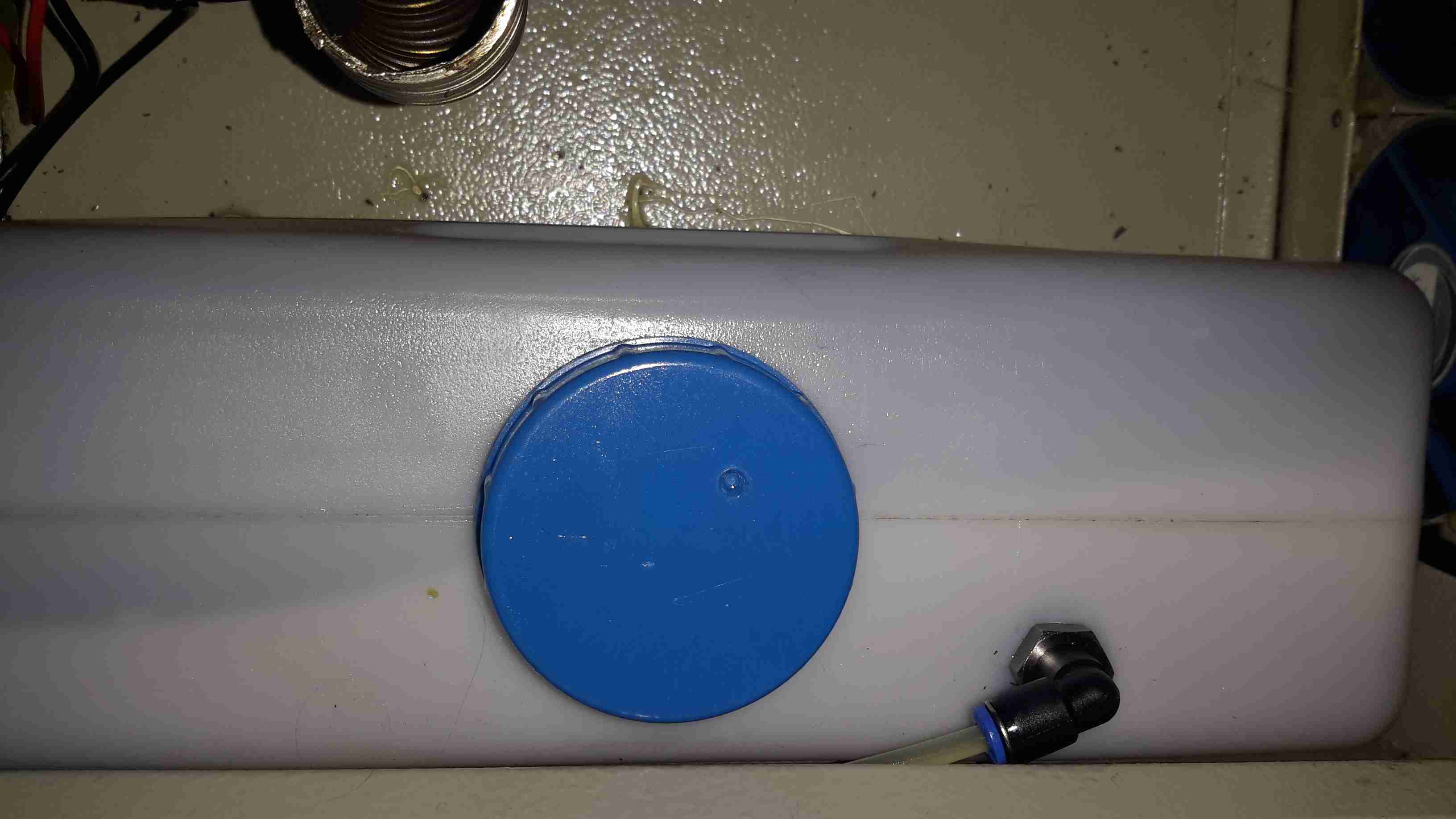
Fuel Tank
The tank I’ve used just so happened to be the perfect size to fit into the base box, and to tap the fuel off a bulkhead fitting was put into the top of the tank, with a dip tube on the other side. The fuel line itself is tiny – only 4mm.
If the specifications from Eberspacher are to be believed, 2L of fuel on board will allow the system to run for about 8 hours on full power, or 16 hours on minimum power.
Being inside the base, refuelling is a little awkward at the moment, the heater has to completely cool before the exhaust can be detached without receiving a burn, so I’ll be building in a fuel transfer system from an external jerry can later to automate the process – this will also help to avoid messy fuel spills.
More to come when the rest of the system is worked out!
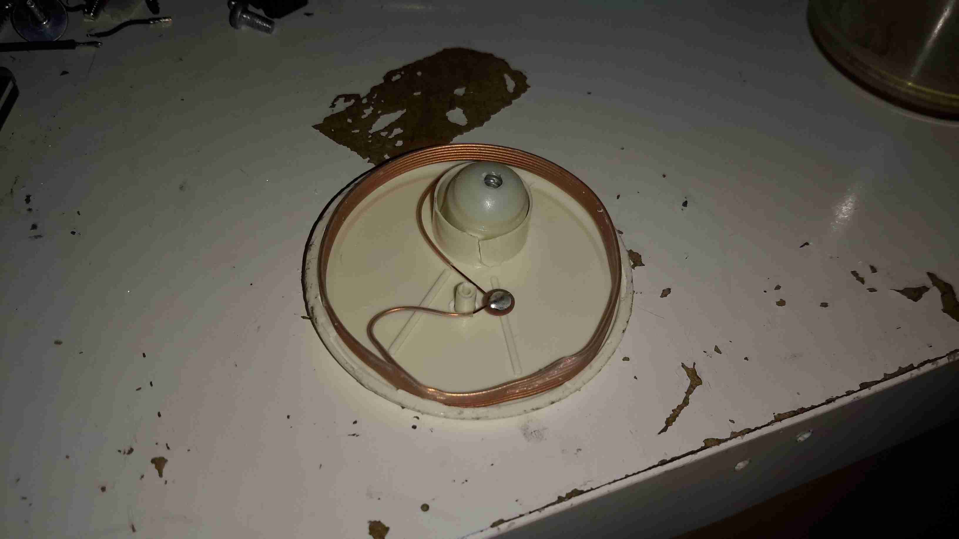
Everyone at some stage must have seen these EAS security tags in shops, usually attached to clothing with a steel pin. As some of this year’s presents had been left with the tags attached, I had to forcibly remove them before wrapping could commence.
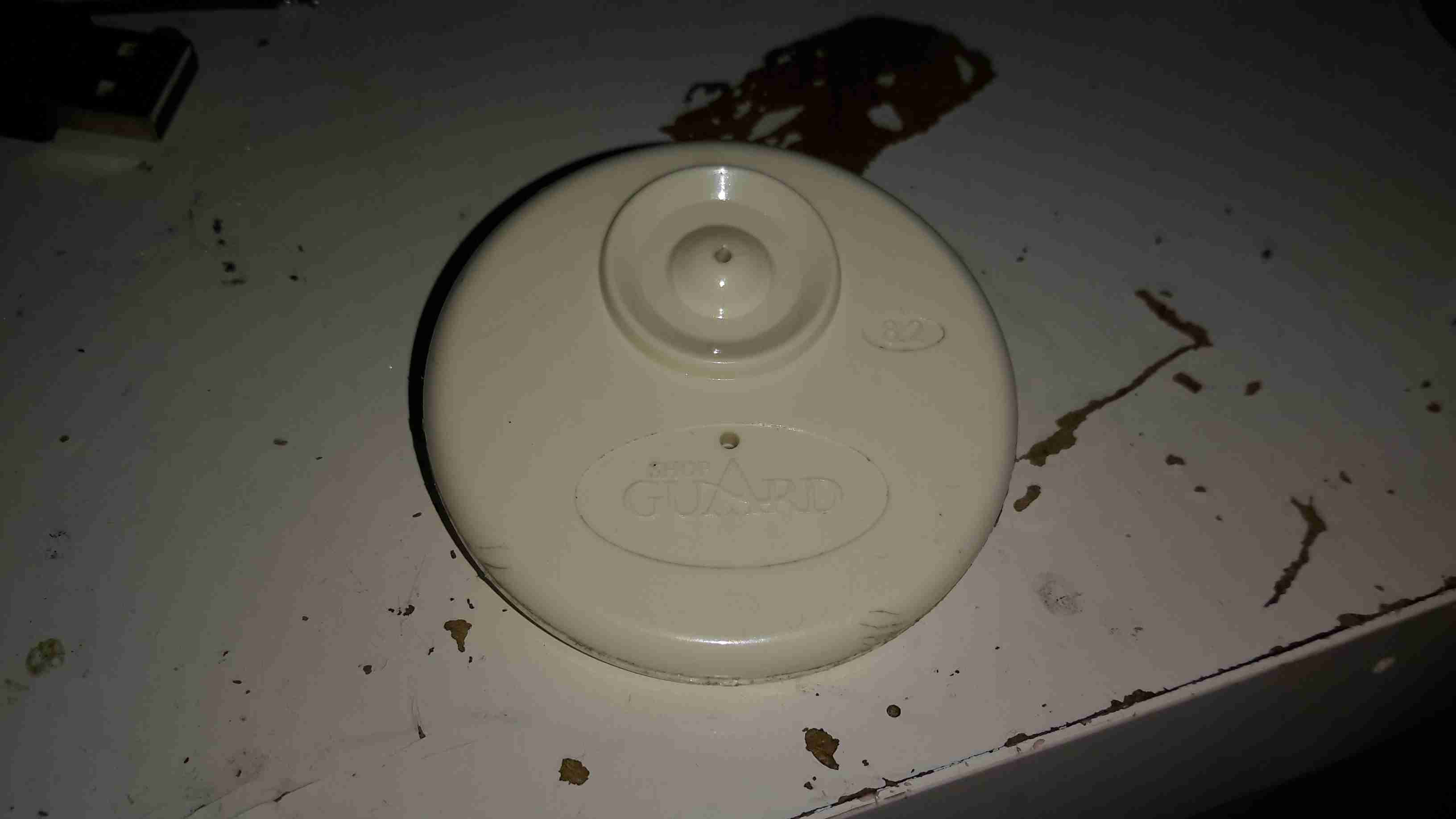
Reverse Side
These are just a plastic disc about 50mm in diameter, with an internal locking mechanism & RF tag inside.
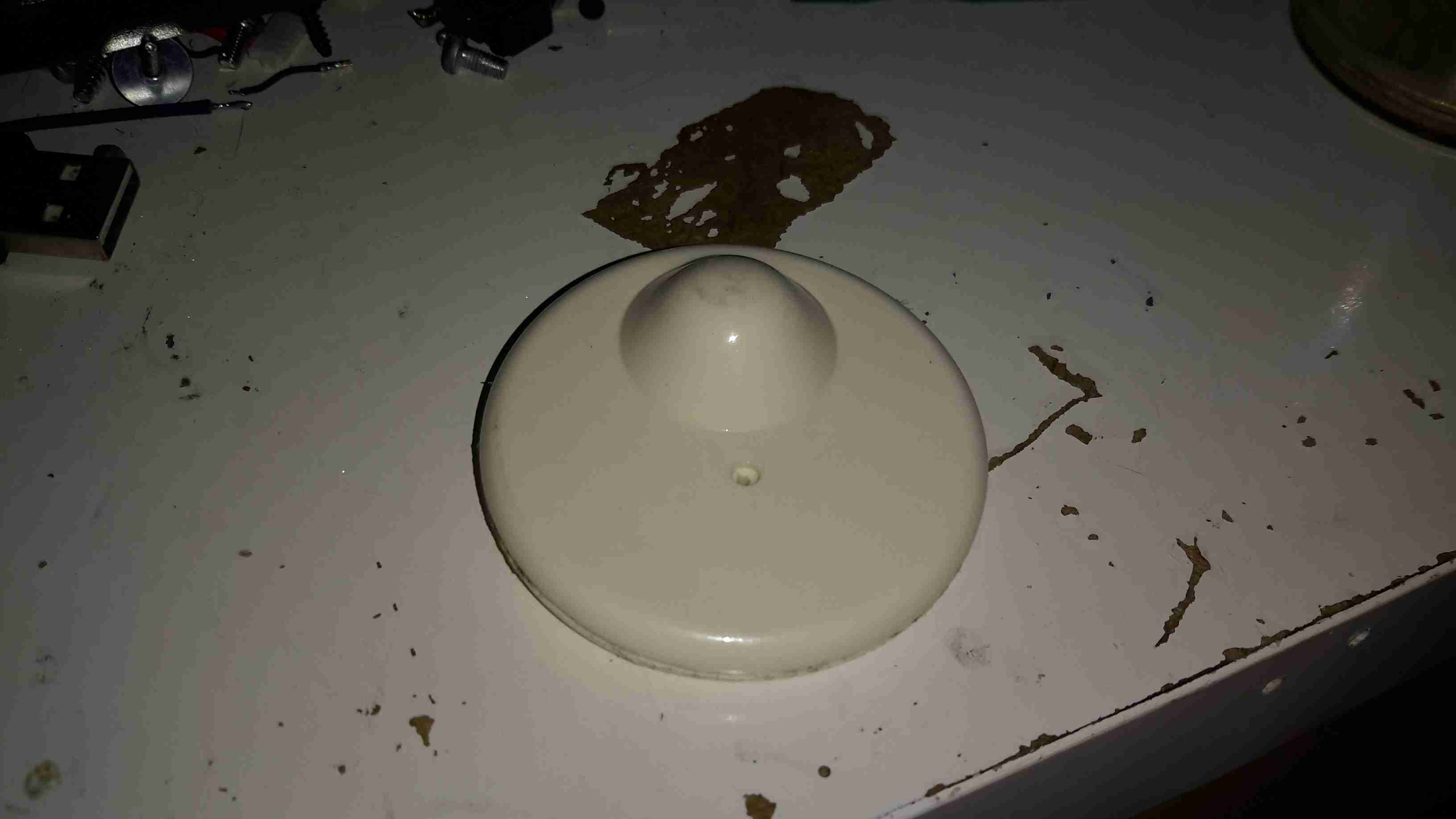
RF Coil
After some careful attack with a saw around the glue seam, the tag comes apart into it’s halves. The RF coil & it’s ceramic capacitor can be seen wrapped around the outside of the tag. The capacitor in this case isn’t even epoxy dipped to save that extra 0.0001p on the manufacturing price. In the top centre is the pin locking mechanism, enclosed in a small plastic pill.
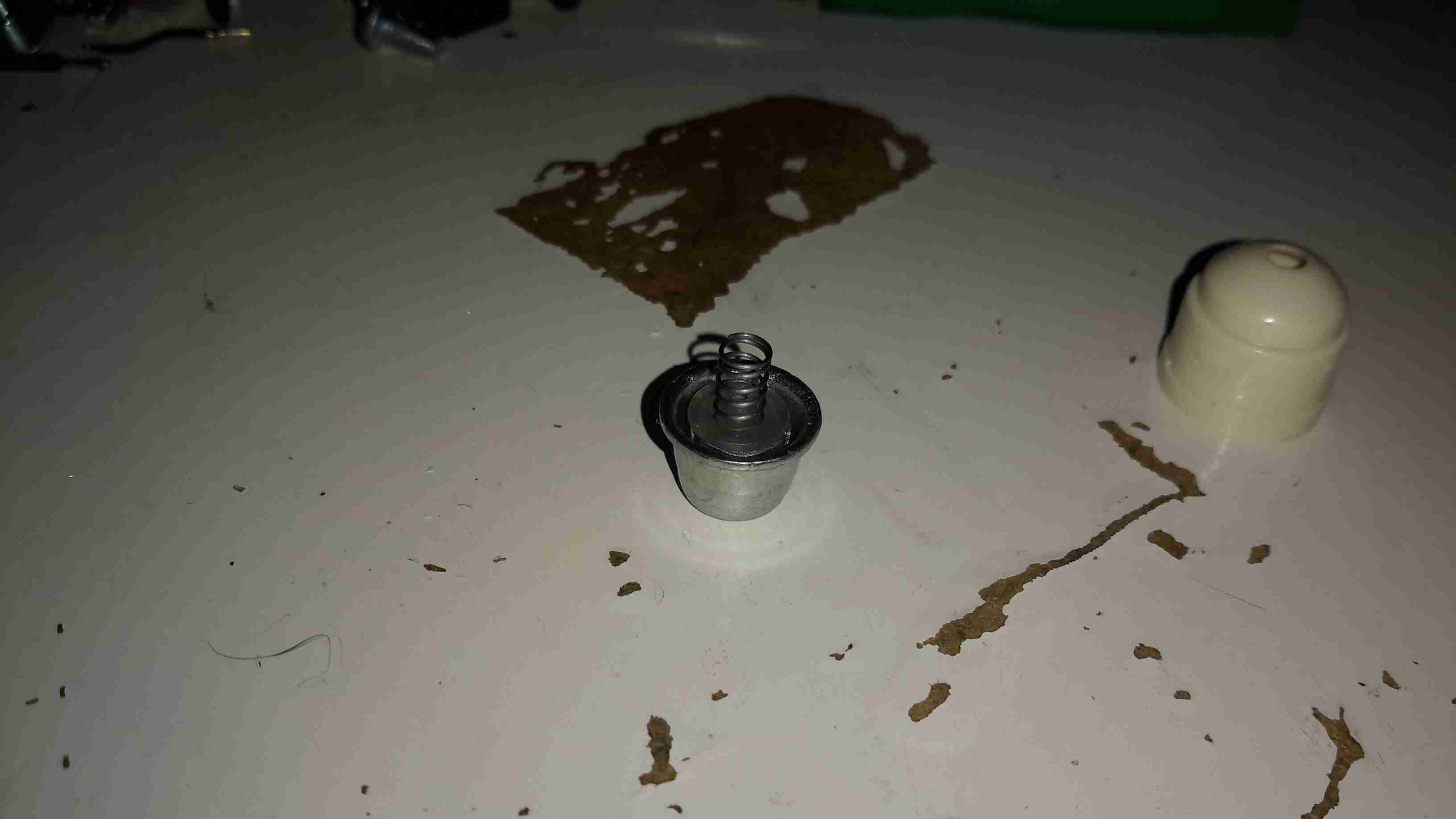
Lock Pill
Popping off the back cap of the lock shows it’s internals.
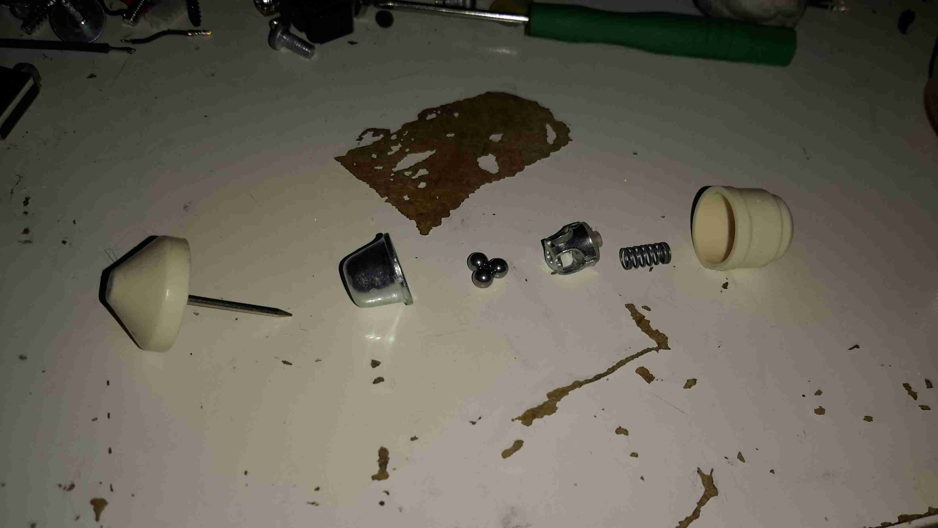
Ball Bearing Lock Assembly
The lock itself is very simple. The centre section, held in place by a spring, carries 3 small ball bearings. The outer metal frame of the lock is conical in shape.
When the pin is pushed into the tag, the conical shape of the lock chamber causes the ball bearings to grab onto it, helped by the action of the spring that pushes the ball bearing carrier further into the cone.
This also means that any attempt to force the mechanism causes it to lock tighter onto the pin.
In normal operation, removal is achieved by a strong magnet that pulls the ball bearing carrier back slightly against it’s spring, allowing the pin to disengage & be pulled out.
This design is incredibly simple & cheap to make, and gains it’s locking strength from friction alone.
I would consider the RF coil being around the outer edge of the device a bit of a security risk – a quick chop with a sharp pair of wire cutters would disable the tag’s alarm functionality instantly. Making the coil slightly smaller & keeping it out of reach of the edge of the tag would help in this regard.
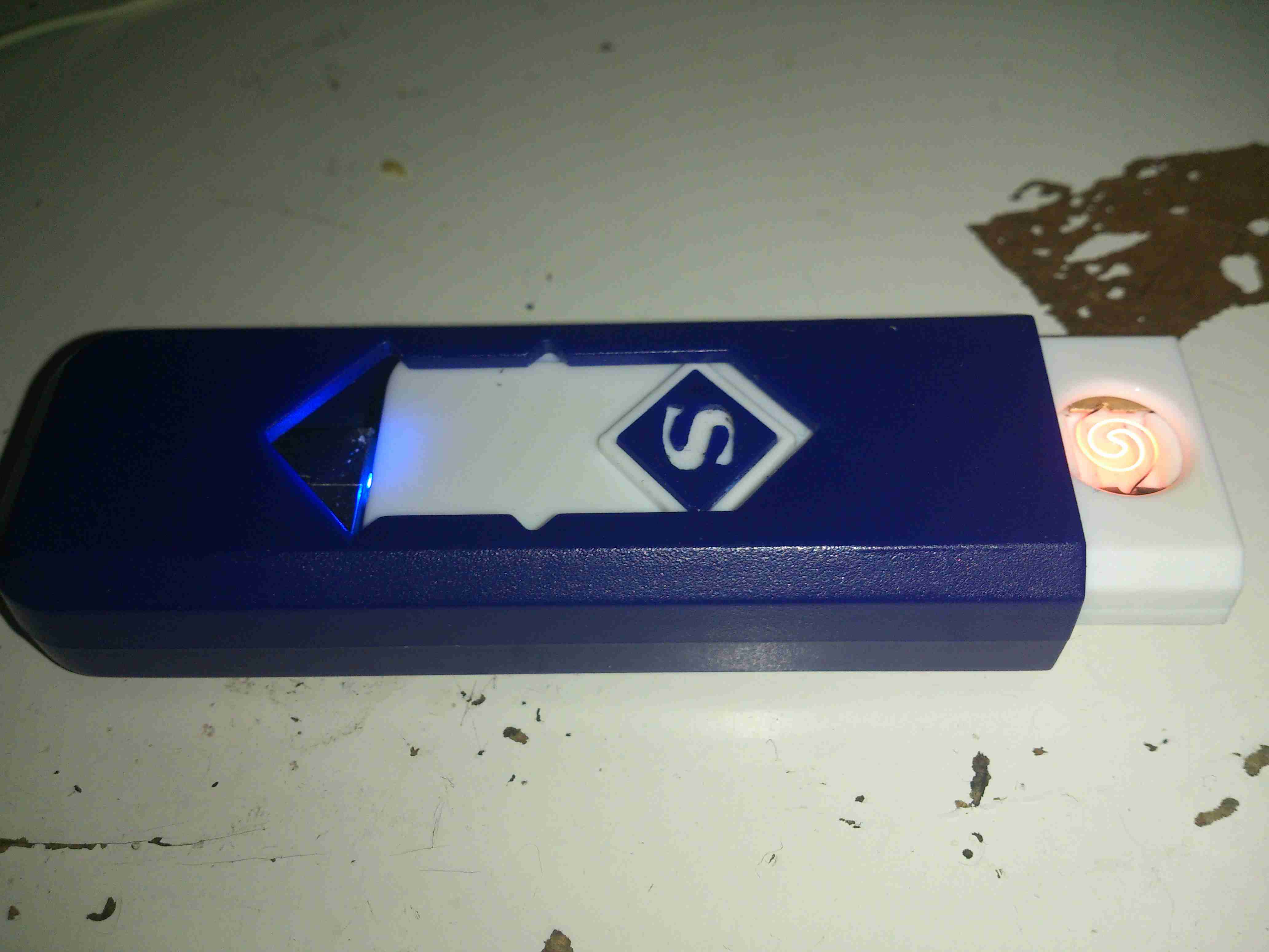
With a recent order from a Chinese seller on eBay, this little gadget was included in the package as a freebie:
Electronic Lighter
I’ve not smoked for a long time, so I’m not too sure what use I’m going to find for this device, but it’s an electronic lighter!
Pyromaniac Mode
Pushing the slider forward reveals a red-hot heater, mounted in the plastic (!) frame.
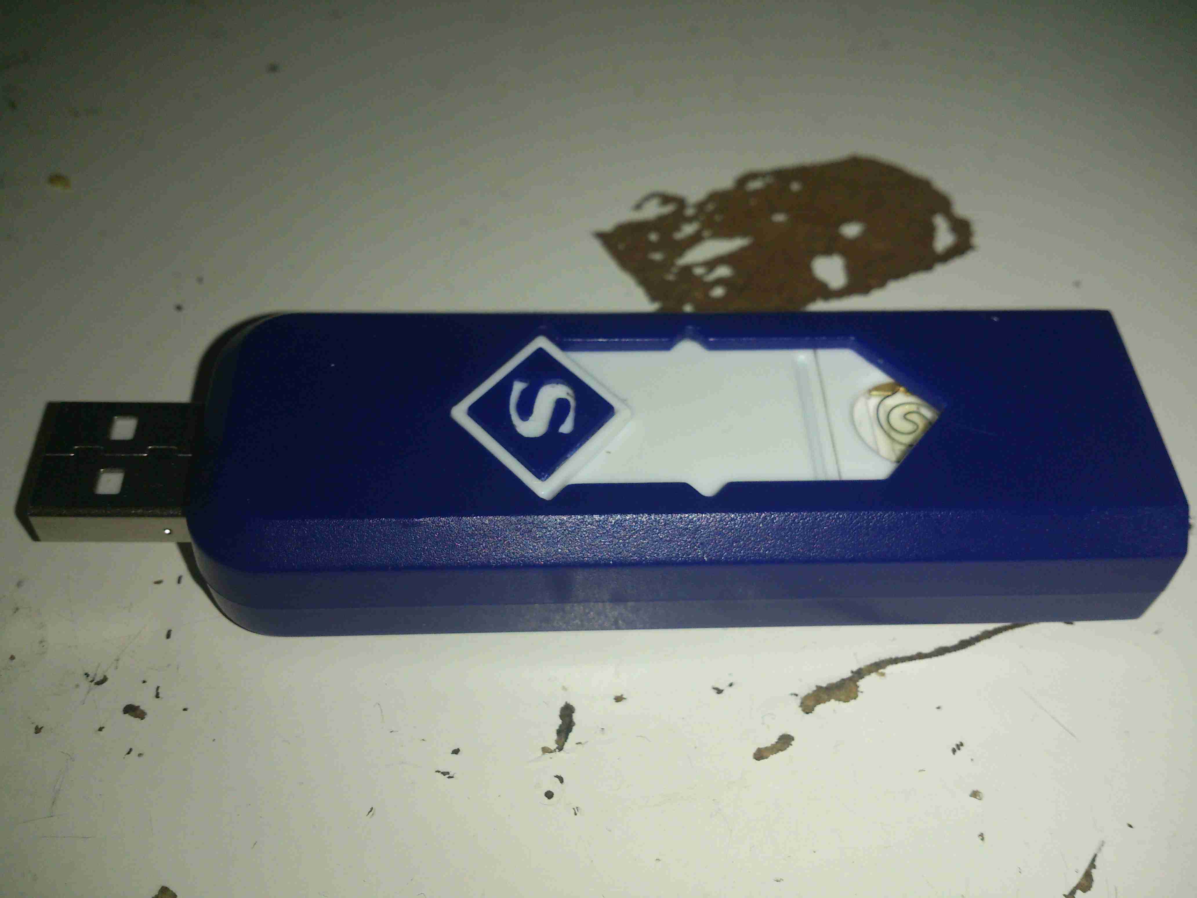
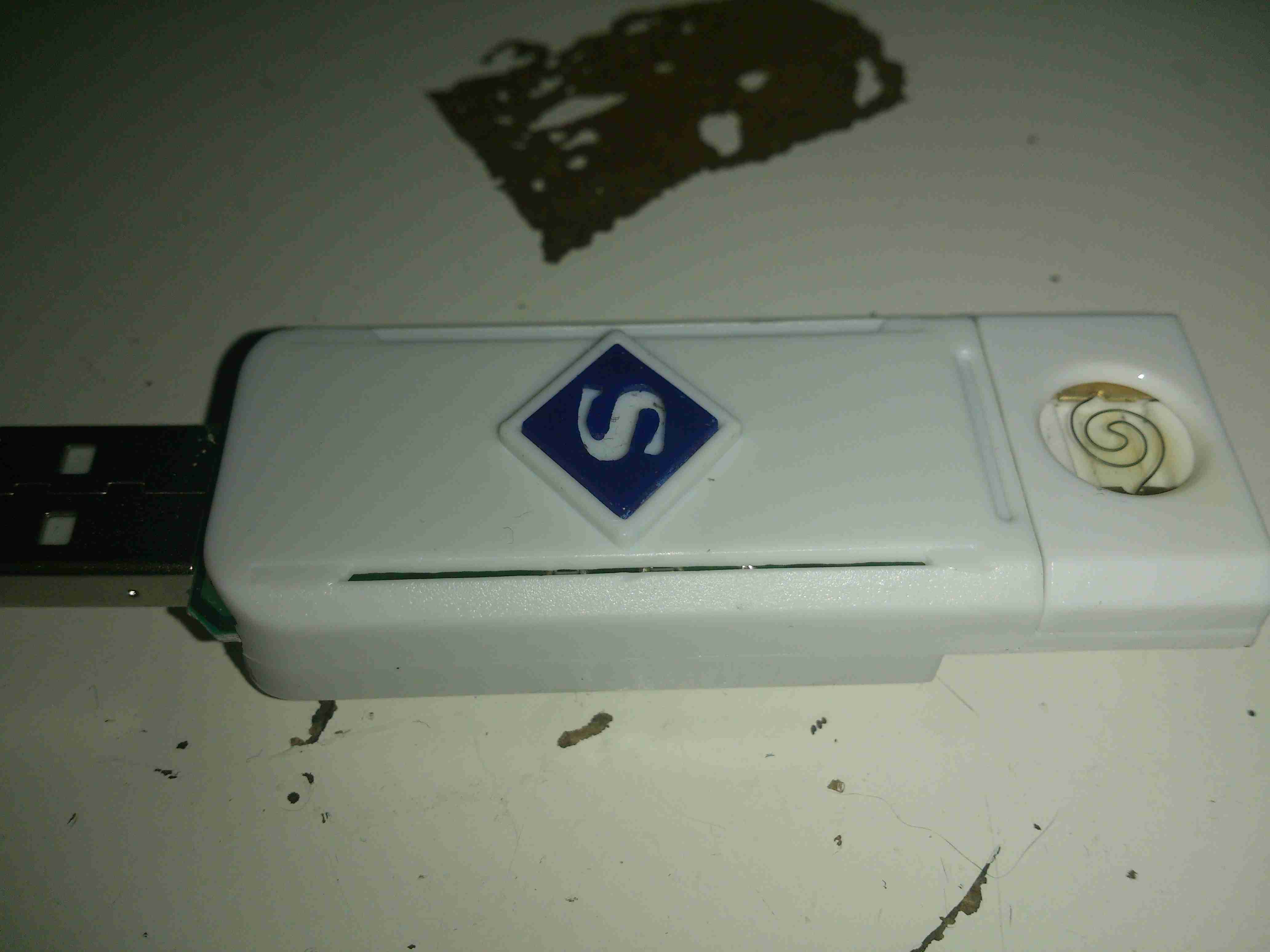
Charging Mode
Pushing the other way reveals a USB port to charge the internal battery.
Core Removed
A couple of screws releases the end cap from the cover & the entire core unit slides out. Like all Chinese toys it’s made of the cheapest plastic imaginable, not such a good thing when heat is involved.
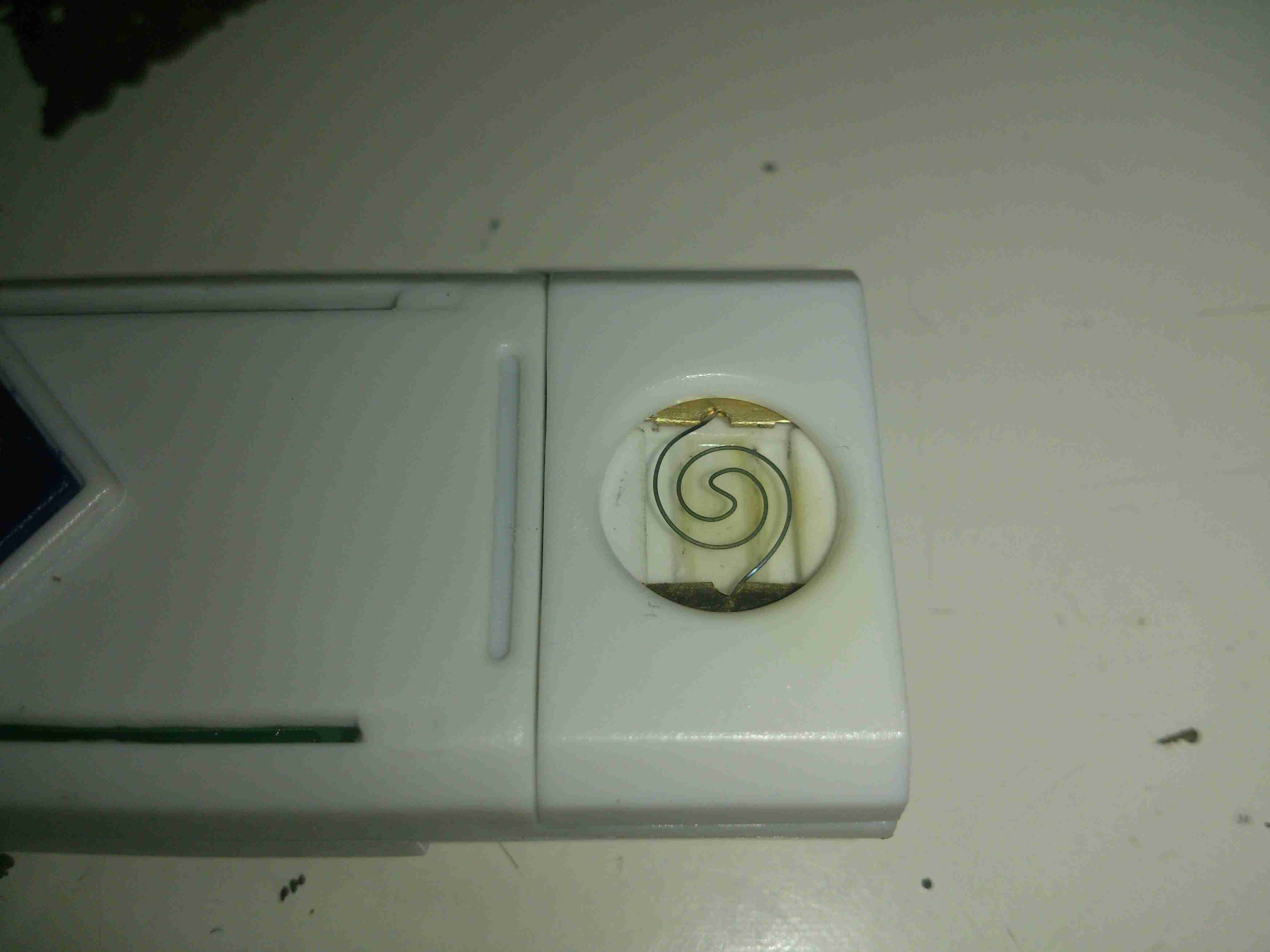
Heating Element
The element itself is a simple coil of Nichrome wire, crimped to a pair of brass terminals. The base the heater & it’s terminals are mounted to is actually ceramic – the surround though that this ceramic pill clips into is just the same cheap plastic. Luckily, the element only remains on for a few seconds on each button push, there’s no way to keep it on & start an in-pocket fire, as far as I can see.
Main PCB
The main PCB clips out of the back of the core frame, the large pair of tinned pads on the left connect to the heater, the control IC has no numbering of any kind, but considering the behaviour of the device it’s most likely a standard eCig control IC.
LiPo Cell
The other side of the board has the USB port on the right, the Lithium Polymer cell in the centre, and the power button on the left. The cell itself also has no marking, but I’m guessing a couple hundred mAh from the physical size.
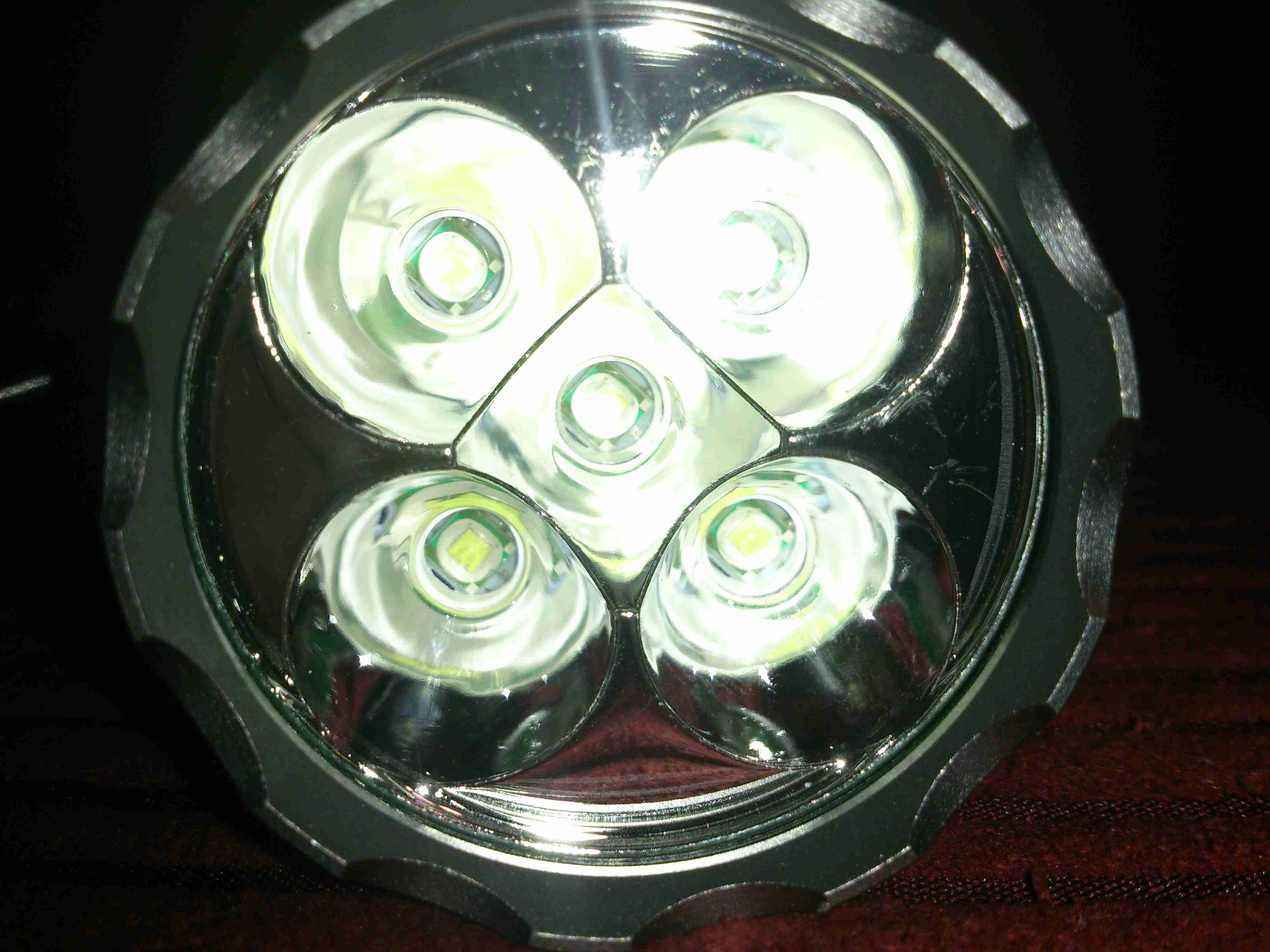
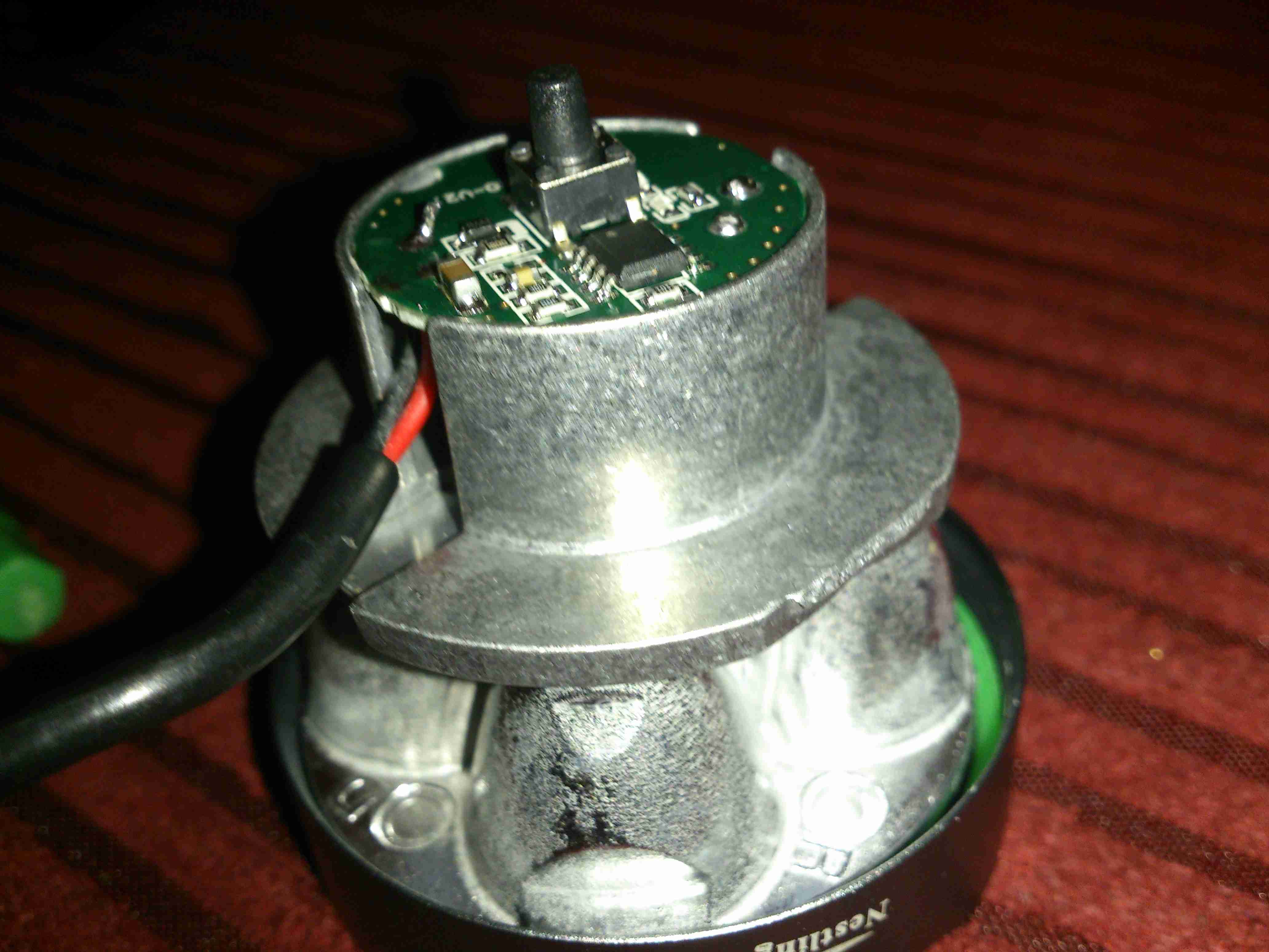
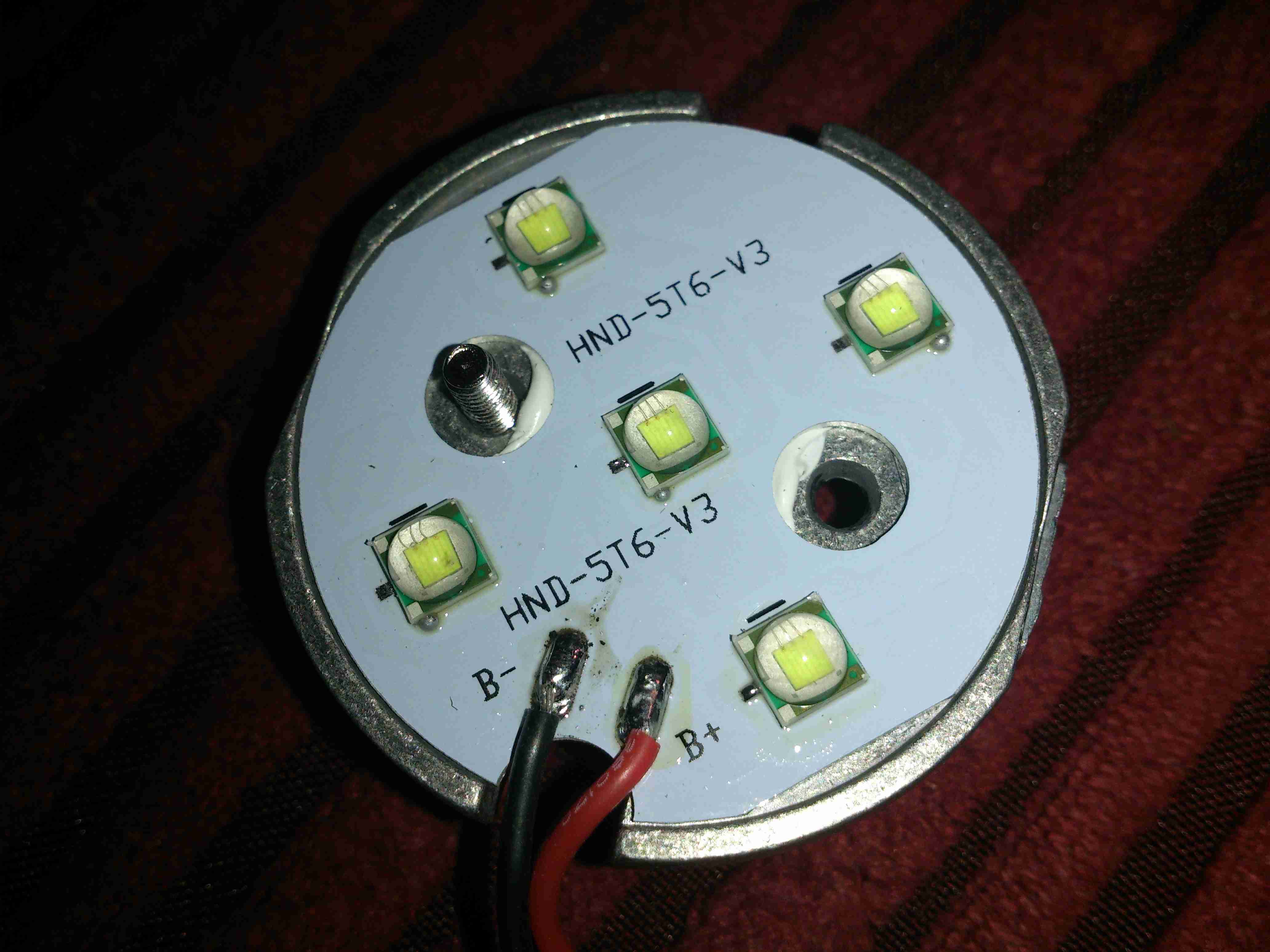
Here’s another torch from eBay, this time with 5 Cree XML-T6 LEDs.
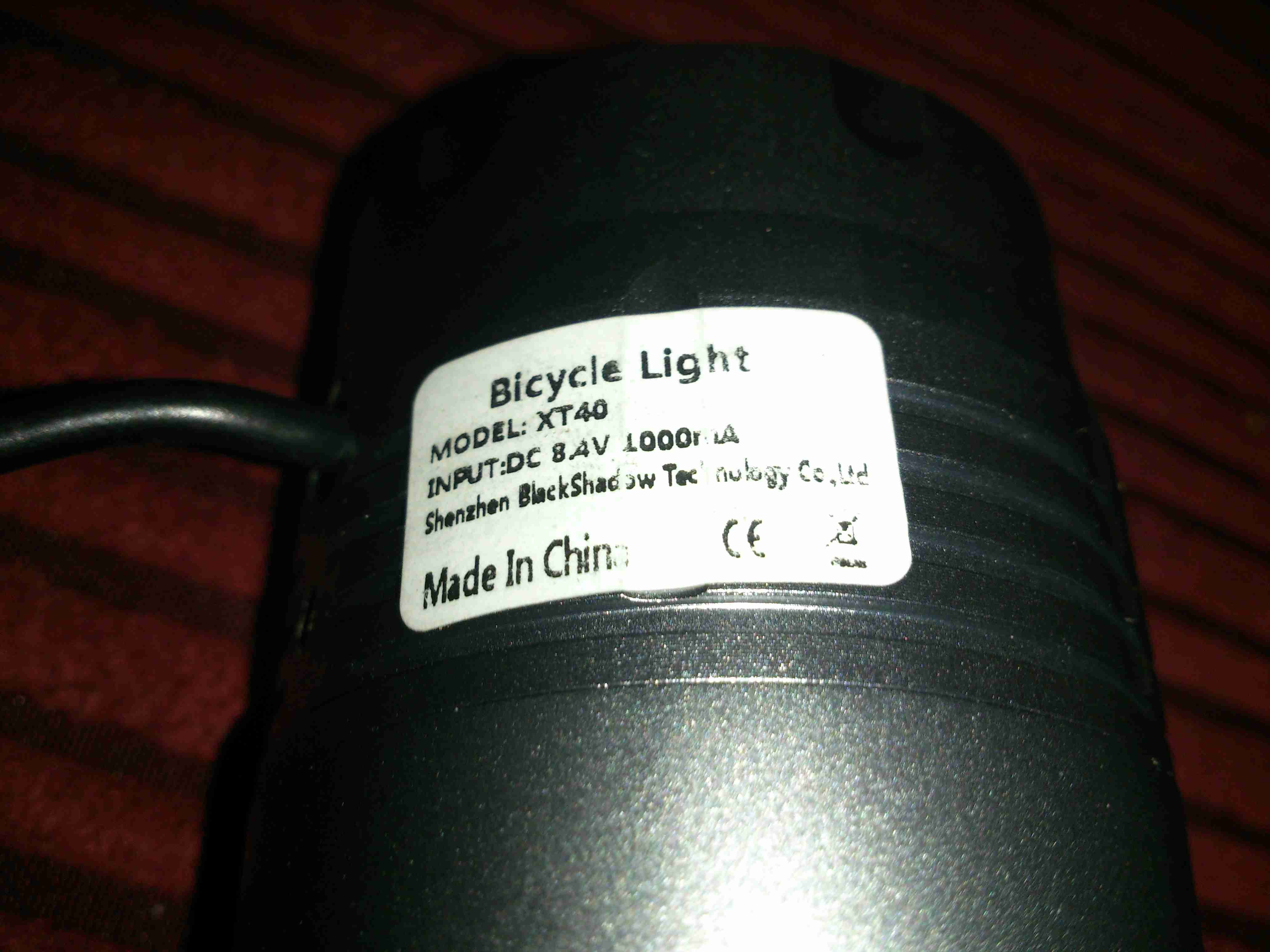
Label
Having 5 Cree LEDs rated at up to 3A a piece, this light has the capacity to draw about 50W from it’s power supply. In this case though, current draw is about 1.5A at 12v input on the full brightness setting.
Cree LED Torch
Here’s the LEDs mounted into the reflector. Fitting this many high power LEDs into a small space requires some serious heatsinking. The casing is made of machined aluminium.
LED Module
Unscrewing the front bezel allows the internals to come out. The core frame & reflector is all cast alloy as well, for heatsinking the LEDs. The controller PCB is mounted into a recess in the back of the LED mount.
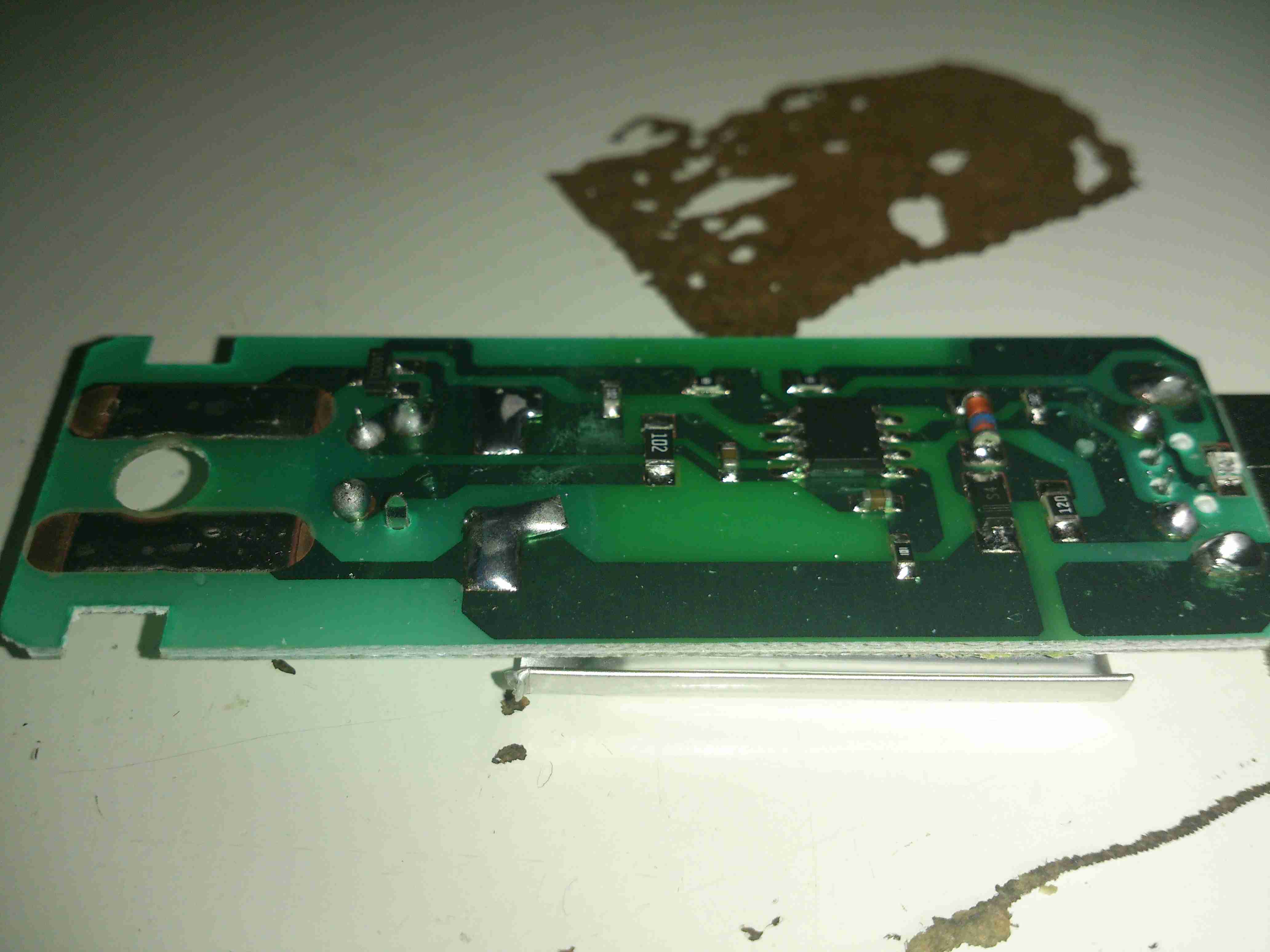
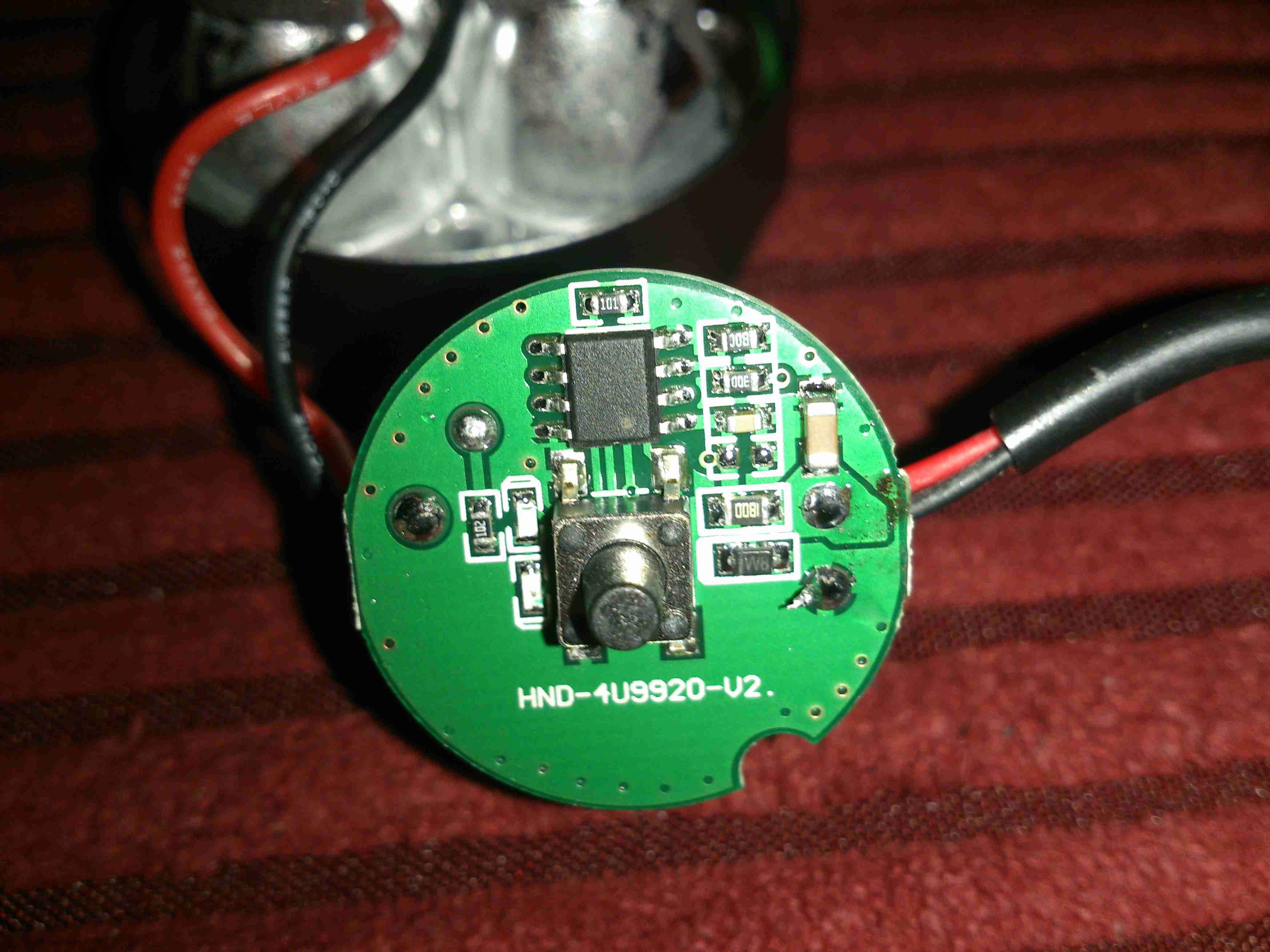
Controller
Here’s the controller itself. The usual small microcontroller is present, for the multiple modes, and handling the momentary power switch.
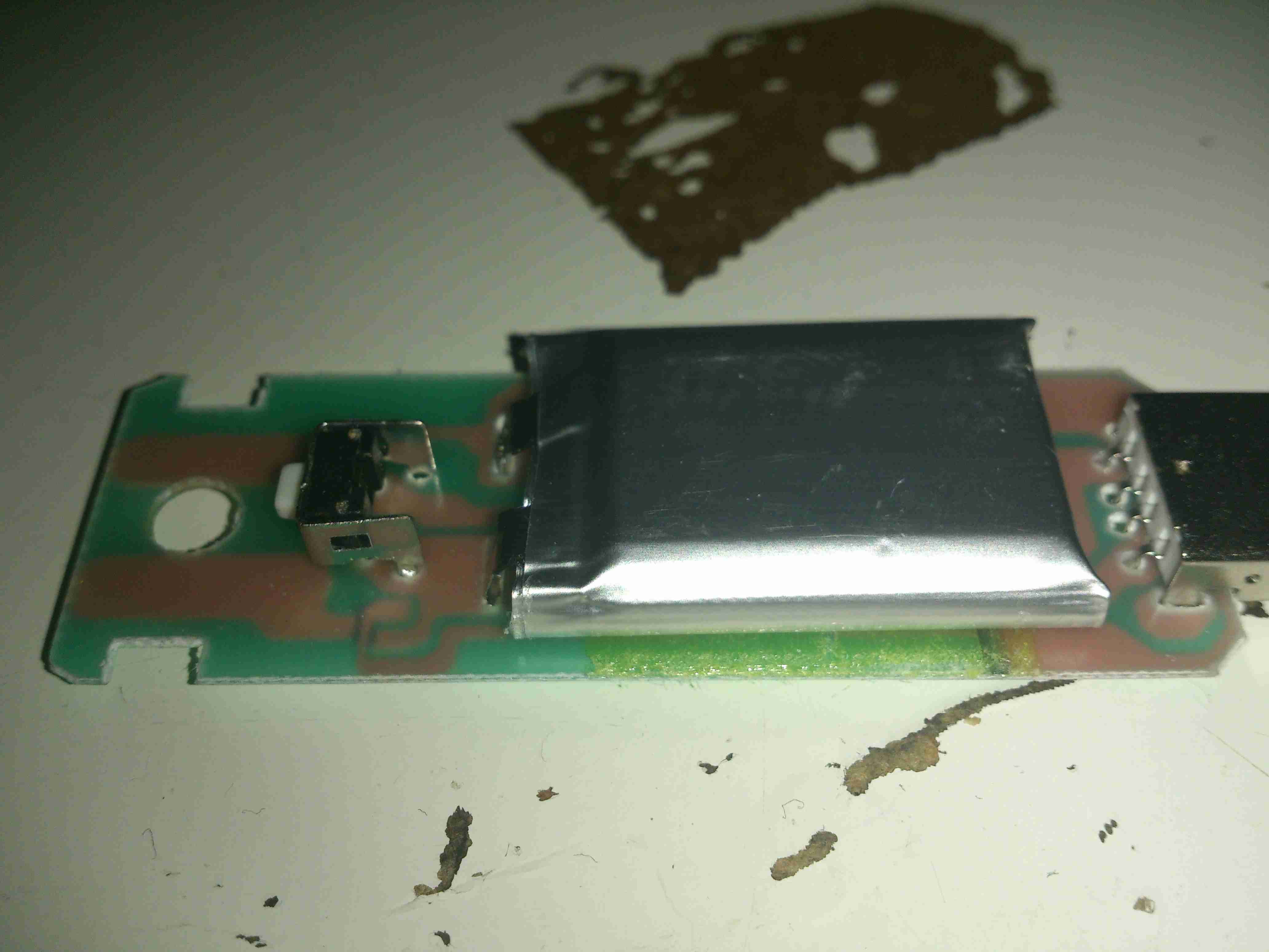
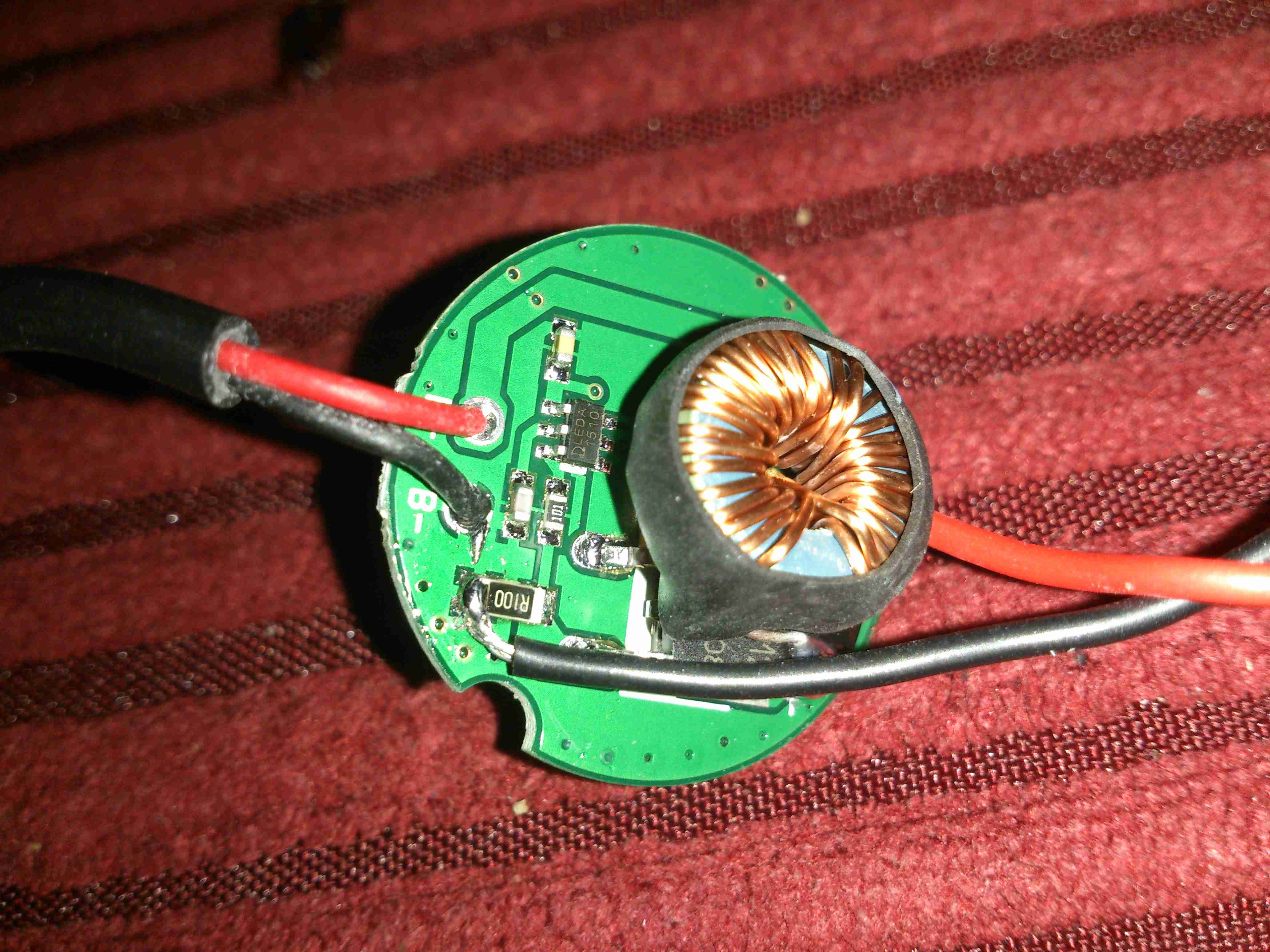
Switching Inductor
As all the LEDs on this torch are connected in series, their forward voltage is ~12-15v. The battery is an 8.4v Li-Ion pack, so some boost conversion is required. This is handled by the circuitry on the other side of the board, with this large power inductor.
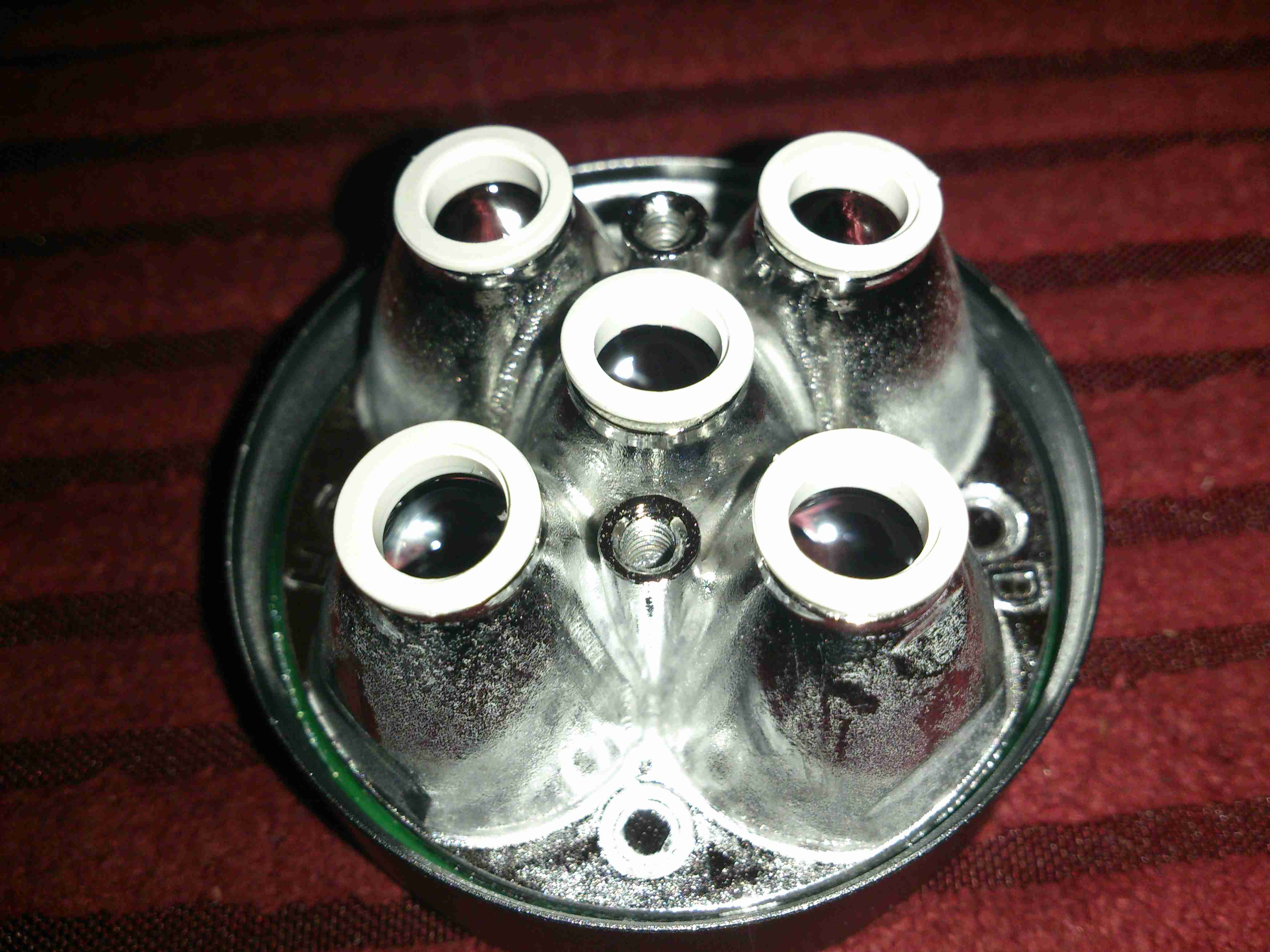
Reflector
The reflector screws onto the front of the LED array, centered in place with some plastic grommets around the LEDs themselves.
LED Array
Finally for the torch, the LED array itself. This is attached to the frame with some thermal adhesive, and the LEDs themselves are mounted on an aluminium-core PCB for better heat transfer.
This module unsurprisingly generates quite some heat, so I have improved the thermal transfer to the outer case with some thermal grease around the outer edge.
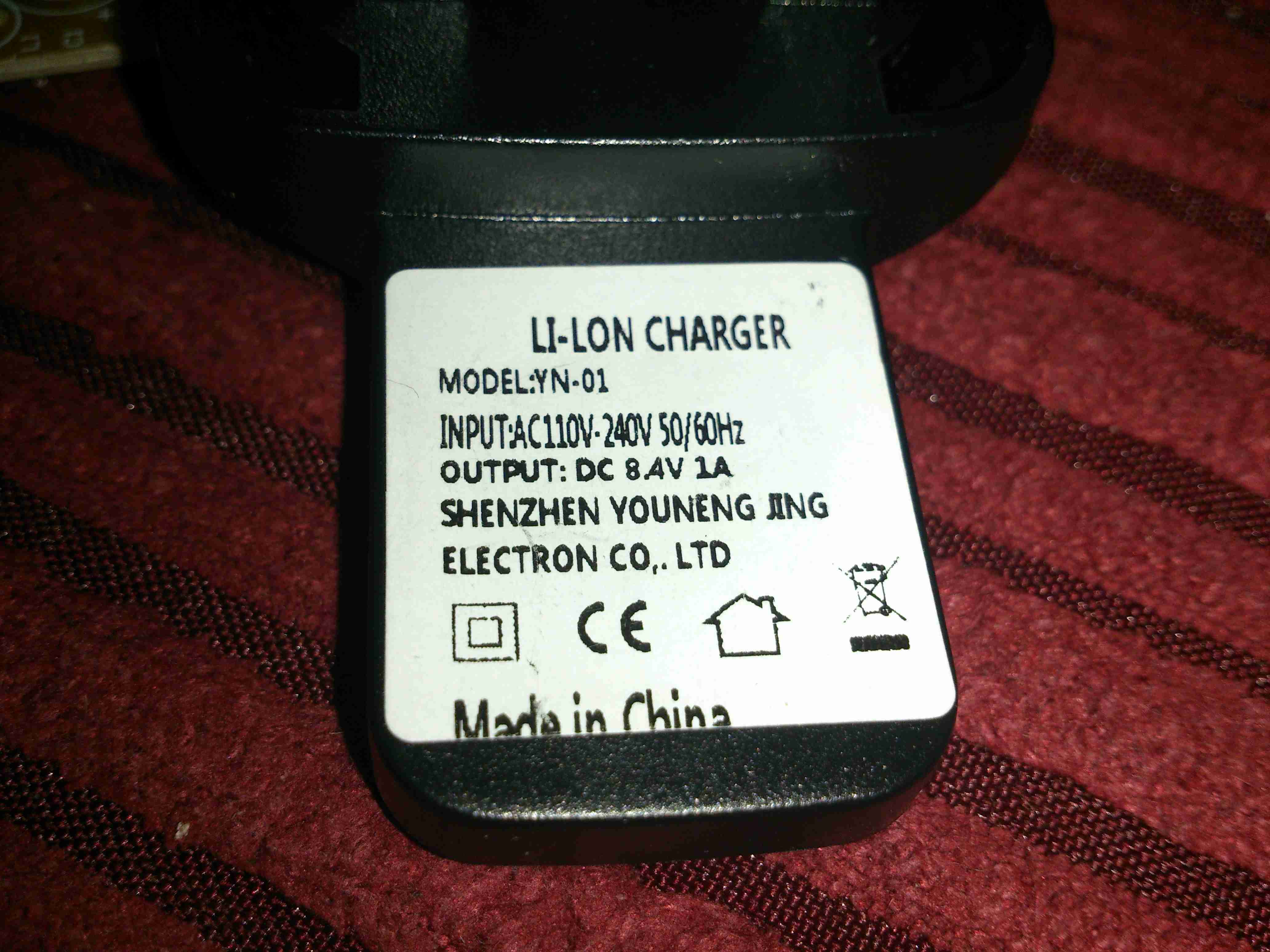
Charger
The supplied charger is the usual Chinese cheapy affair, claiming an output current of 1A at 8.4v. I never use these chargers, so they get butchered instead.
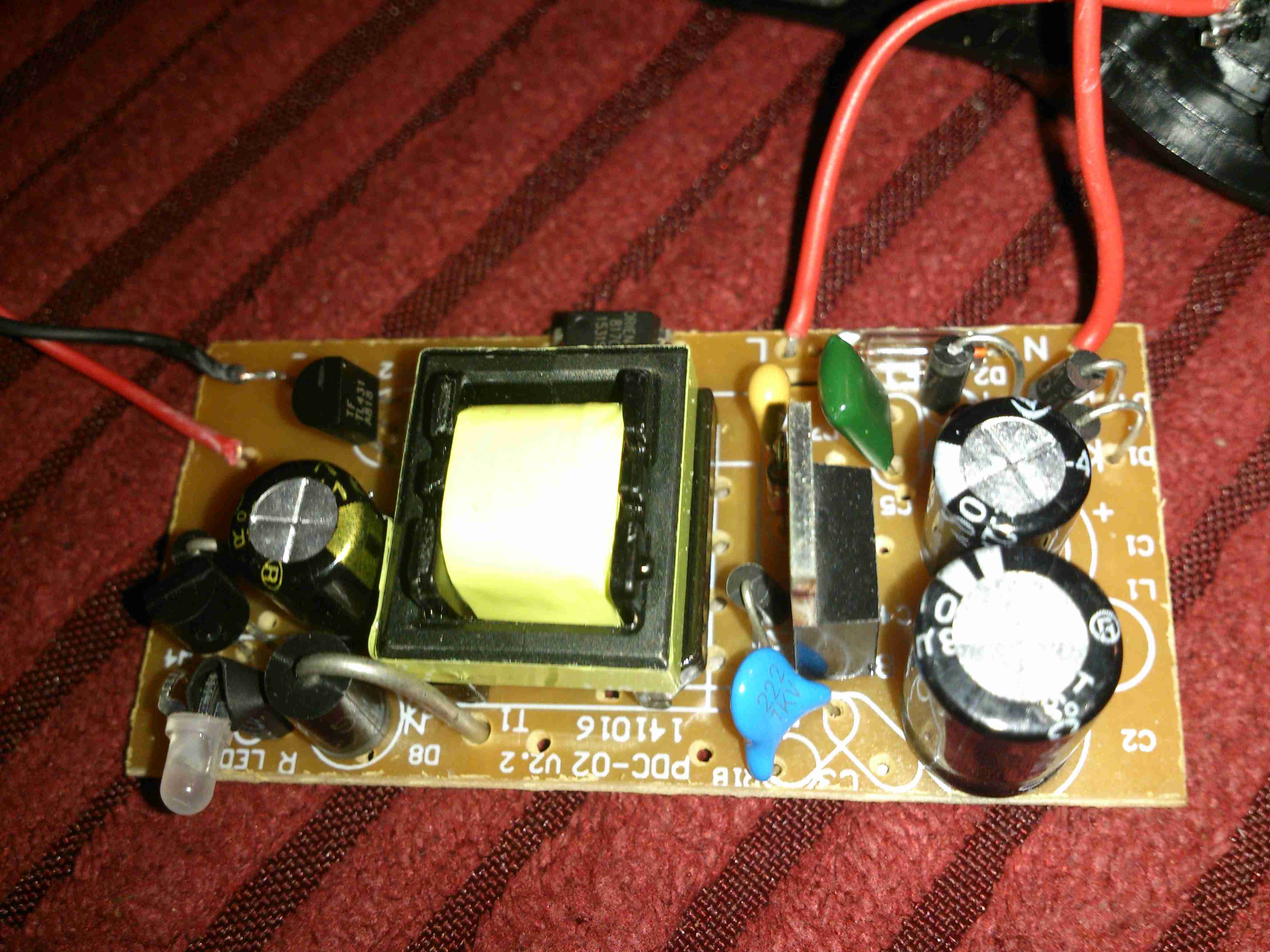
Charger PCB
Here’s the main PCB. Overall the construction isn’t that bad, the input mains is full-wave rectified, but there is little in the way of RFI filtering. The supply is fused, but with an absolutely tiny glass affair that I seriously doubt has the ability to clear a large fault current.
Like many cheap supplies, the output wiring is very thin, it’s capacity to carry 1A is questionable.
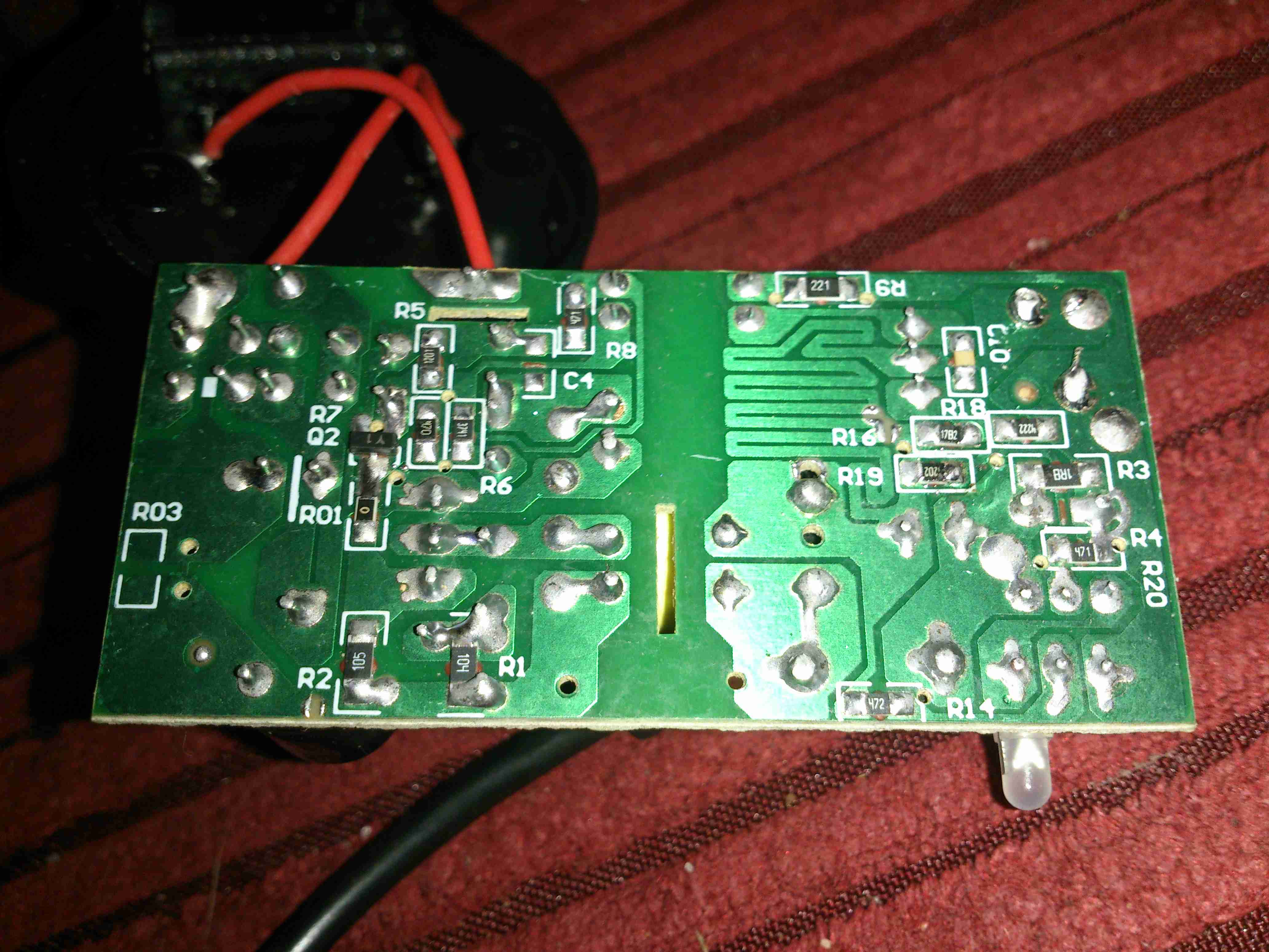
PCB Reverse
On the reverse side, there’s a nice large gap between the mains side & the low voltage output. There’s even an anti-tracking slot under the optoisolator.
To make my timelapse video capture a little easier, I wrote a small script that handles creation of a new folder for every timelapse instance, deals with the runtime & frame interval flags & generally makes everything a little cleaner.
As with most of my code, it’s rough, but functional
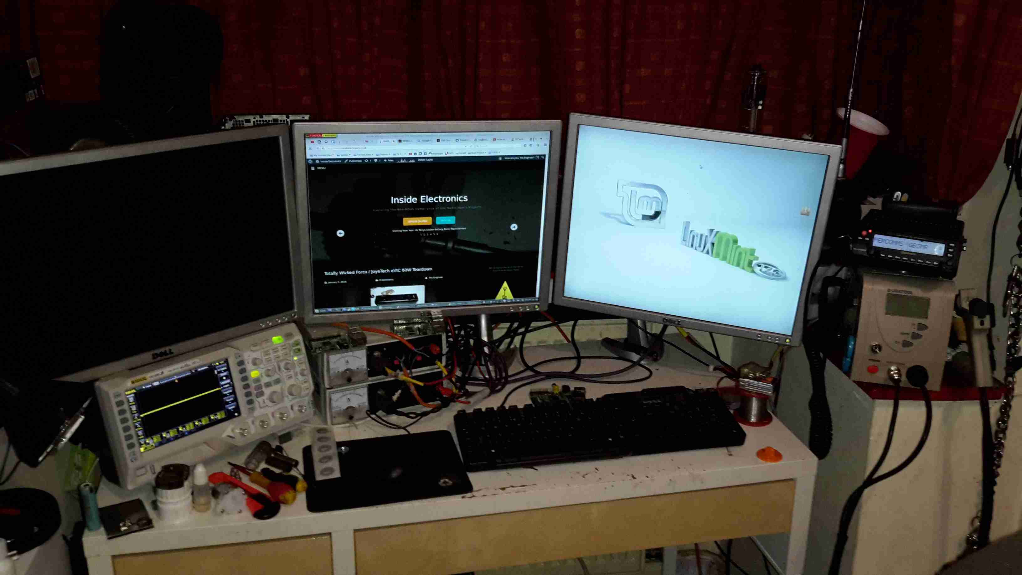
Main radio of course is housed on the left, it’s partially hidden under my currently over-populated breadboard.
All 3 monitors are linked to the same PC, using a pair of video cards. This is a very flexible system with so much screen real estate.
Main system power is provided by the pair of power supplies next to the radio – these are homebrew units using surplus switched mode PSU boards. Check my previous posts for more details.
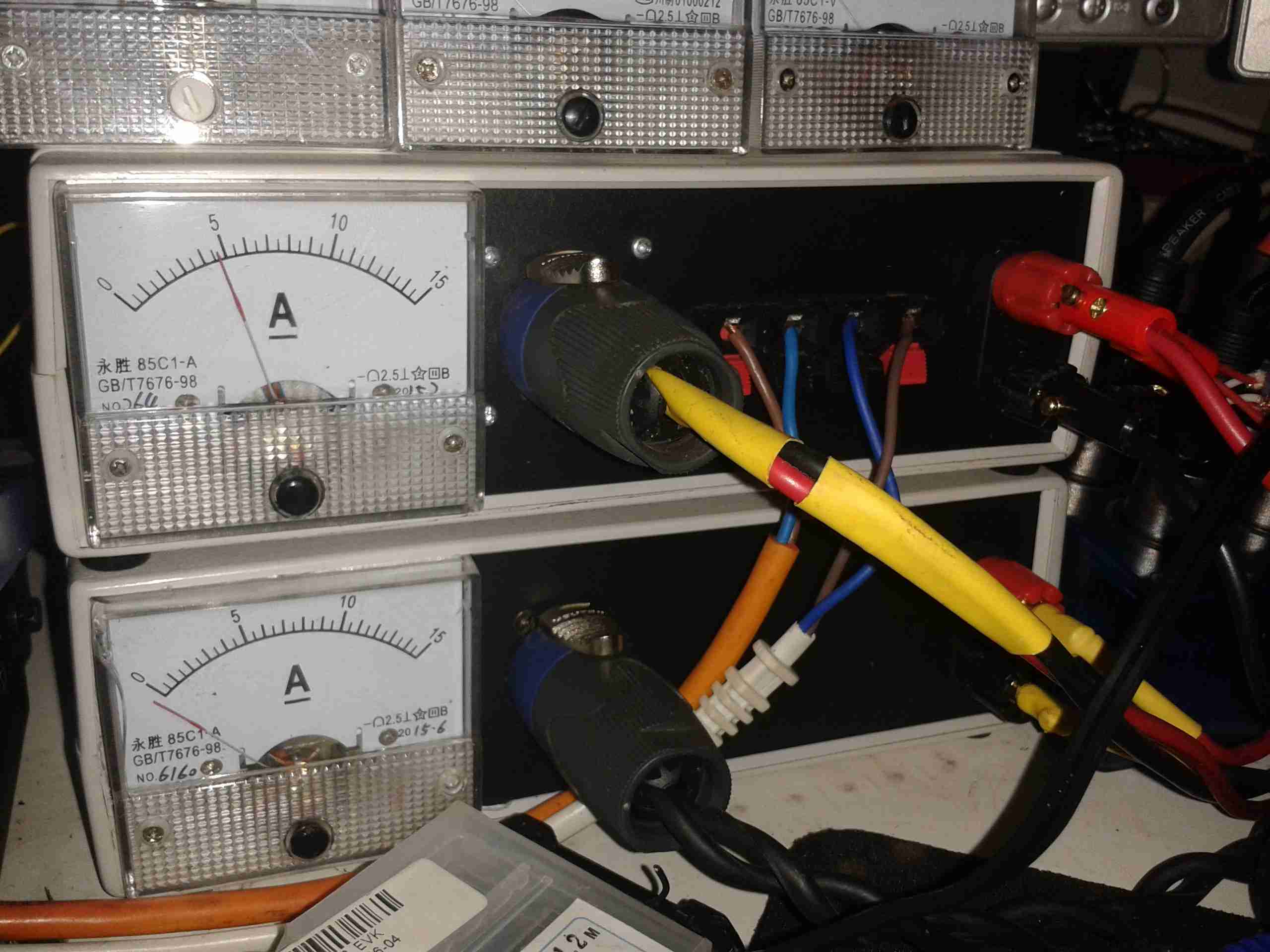
Power Supplies
The mainpowersupply system. These two supplies are cross connected, giving a total DC amperage of 30A at 13.8v. There is also a link to a large 220Ah lead-acid battery bank (orange cable), to keep me on the air during power outages. This cable is getting upgraded to something more beefy shortly. The white cable is currently supplying power to my onlineradiation monitor.
The main high-currentDC outputs are the Speakon connectors next to the meters. The top one is powering the radio directly, the bottom is linked through to my 12v distribution box for lower current loads, such as the oscilloscope, audio amplifiers, tools, etc.
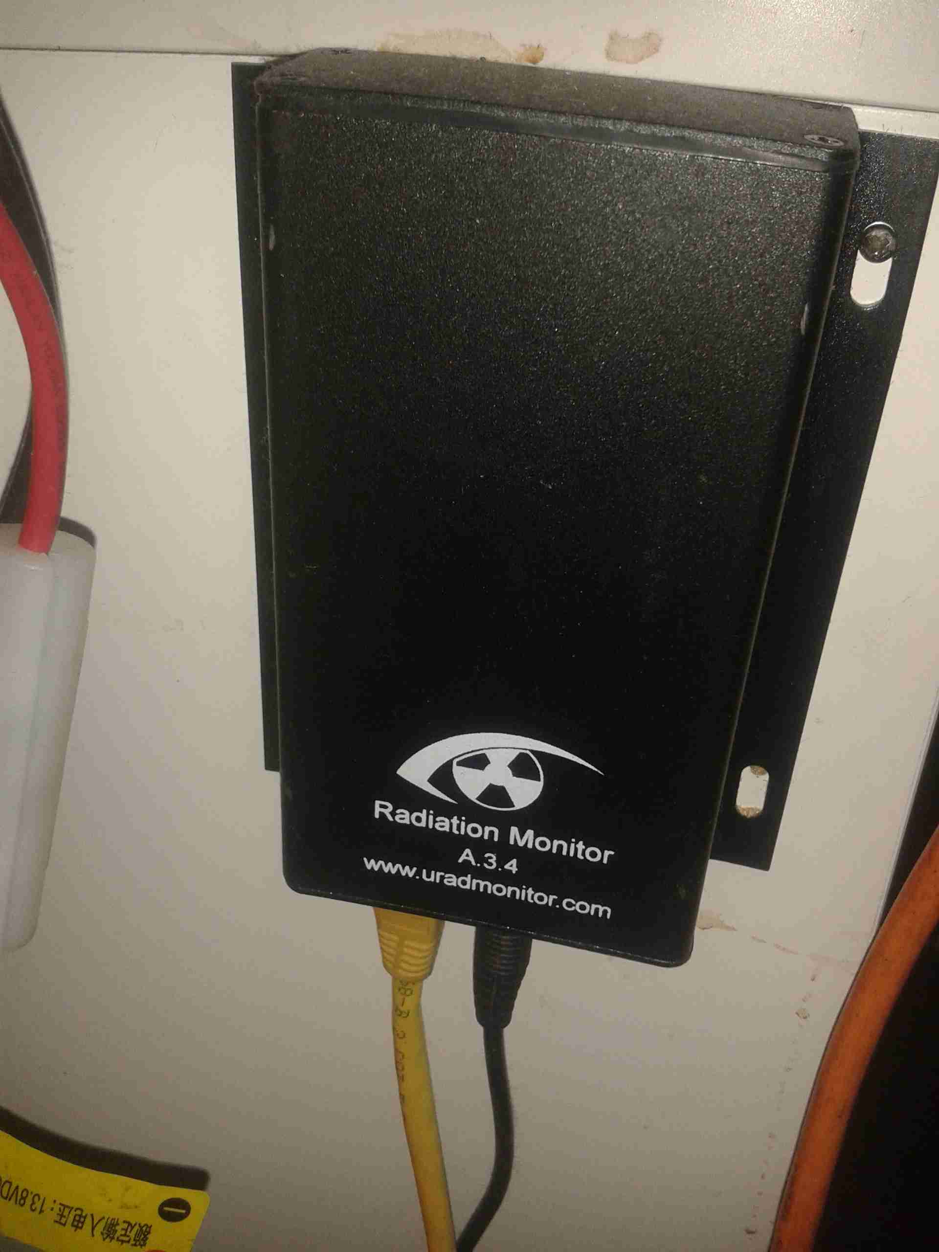
Radiation Monitor
Attached to the side of the desk is the radiation monitor itself.
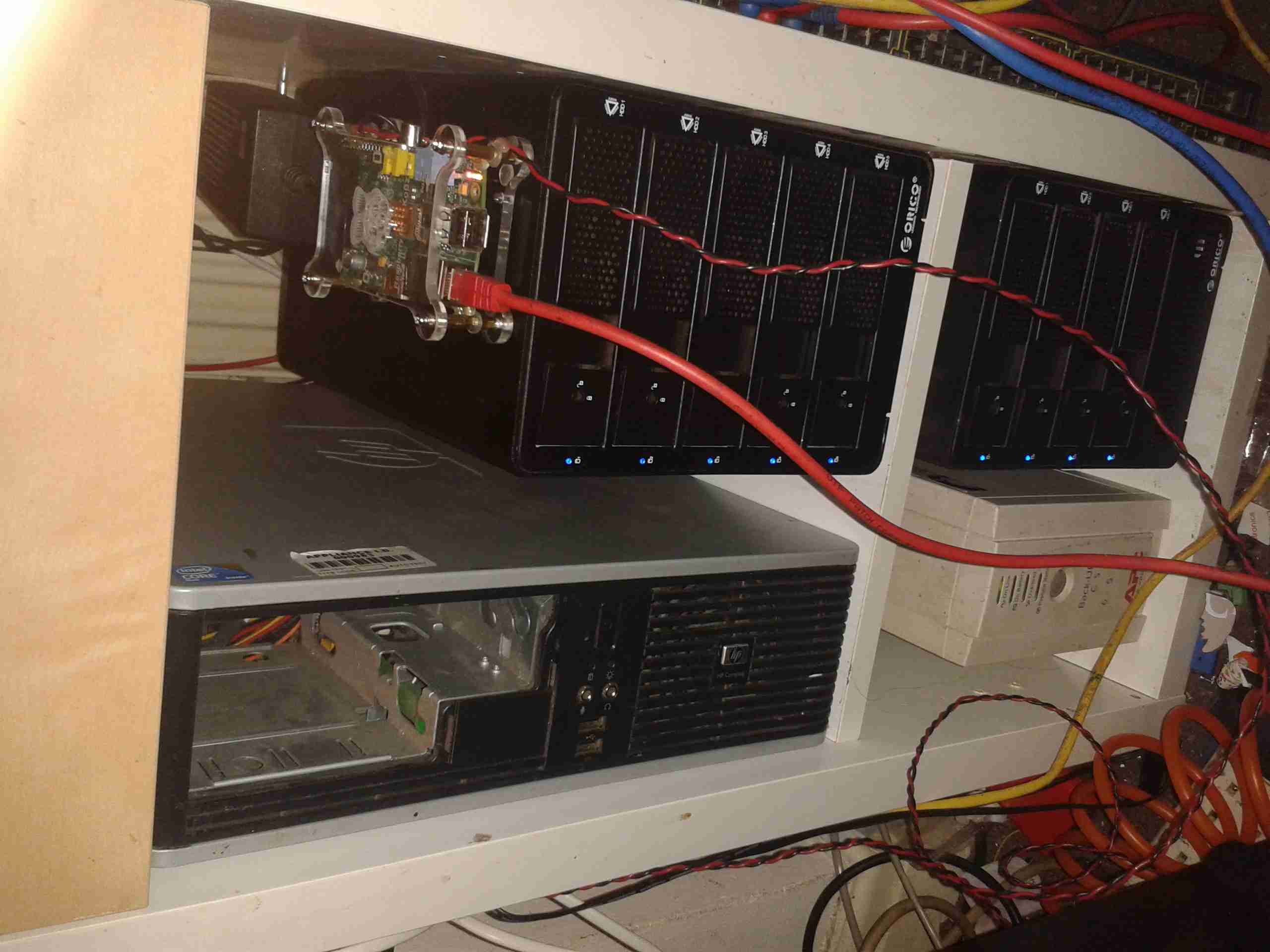
Core NAS
Under the radio is the core NAS of the network. It’s an array of 9 4TB disks, in RAID6, giving a total capacity after parity of 28TB. This provides storage & services to every other machine in the shack, the Raspberry Pi on top of the disk array is doing general network housekeeping & monitoring, also generating the graphs for the Radiation Monitor page. A Cisco 48-portswitch is partially out of frame on the right, providing 100MB Ethernet to the devices that don’t require gigabit.
I often find myself carrying by go bag up to the boat during trips, so I can do some radio. However at 16lbs it’s a pain on public transport. A fixed radio was required! Another Wouxun GK-UV950P was ordered, and the fact that the head unit is detachable from this radio makes a clean install much easier.
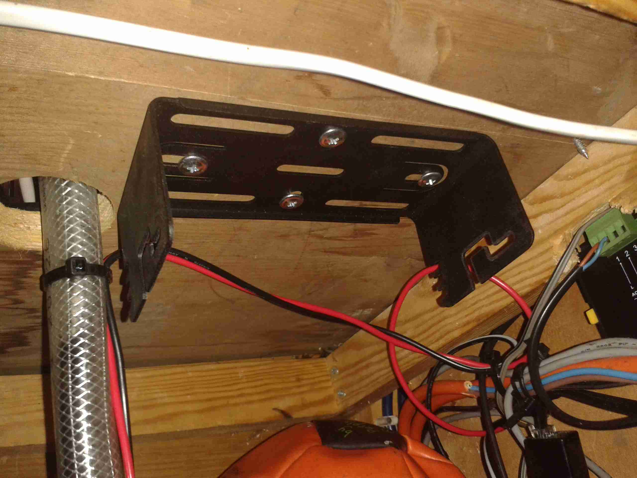
Mounting Bracket
I found a nice spot under a shelf for the main radio unit, above is the mounting bracket installed.
This location is pretty much directly behind where the head unit is placed, but the audio is a bit muffled by the wooden frame of the boat & some external speakers will be required for the future.
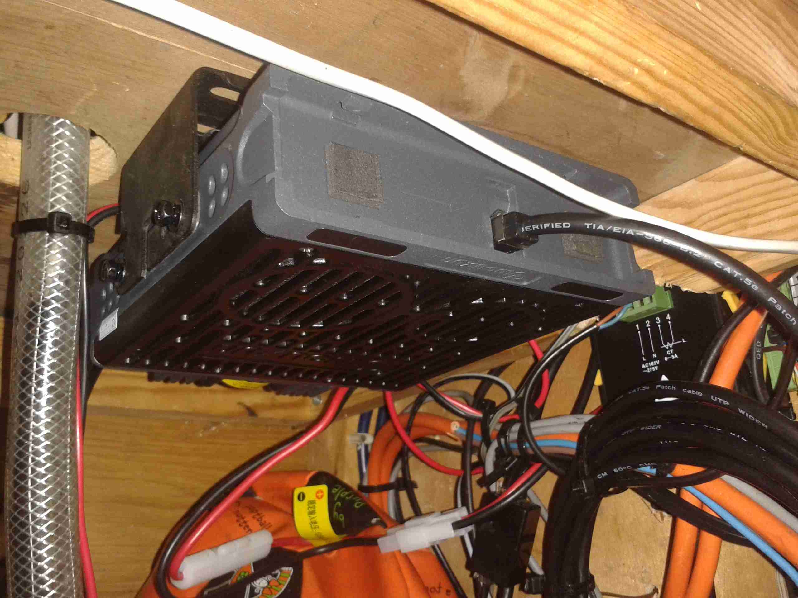
Main Radio Unit
Here’s the main radio unit mounted on it’s bracket, with the speakers facing down to improve the audio slightly. I used the supplied interface cable for the head unit, even though it’s too long. I do have the tools to swage on new RJ-45s, but the stuff is a pain to terminate nicely & I really just couldn’t be bothered. So it’s just coiled up with some ties to keep it tidy. Main power is provided directly from the main DC bus. (880Ah total battery capacity, plus 90A engine alternator, 40A solar capacity).
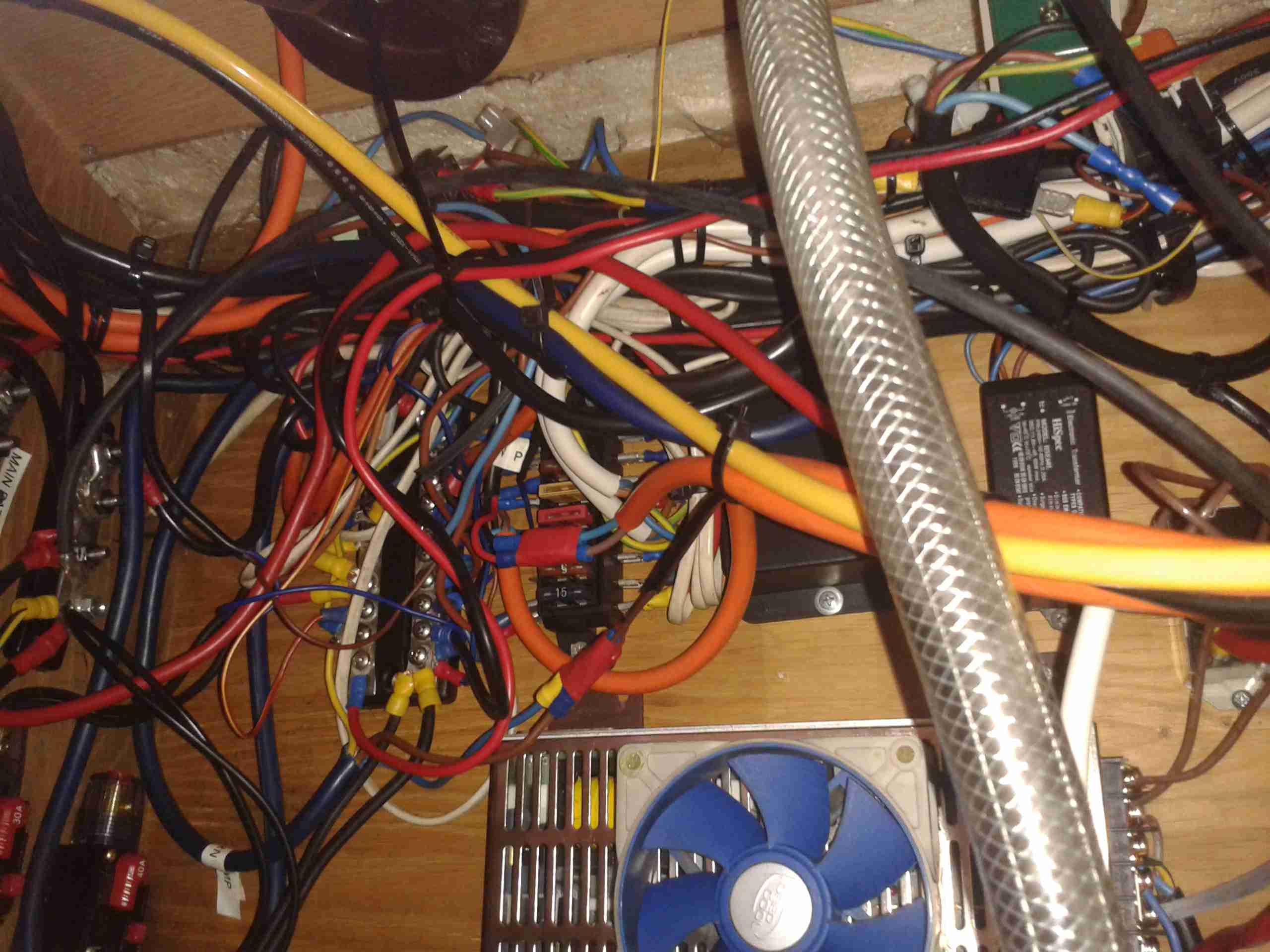
Rat’s Nest
Here’s the main DC bus, with the distribution bars. With the addition of new circuits over the years, this has become a little messy. At some point some labelling would be a good idea!
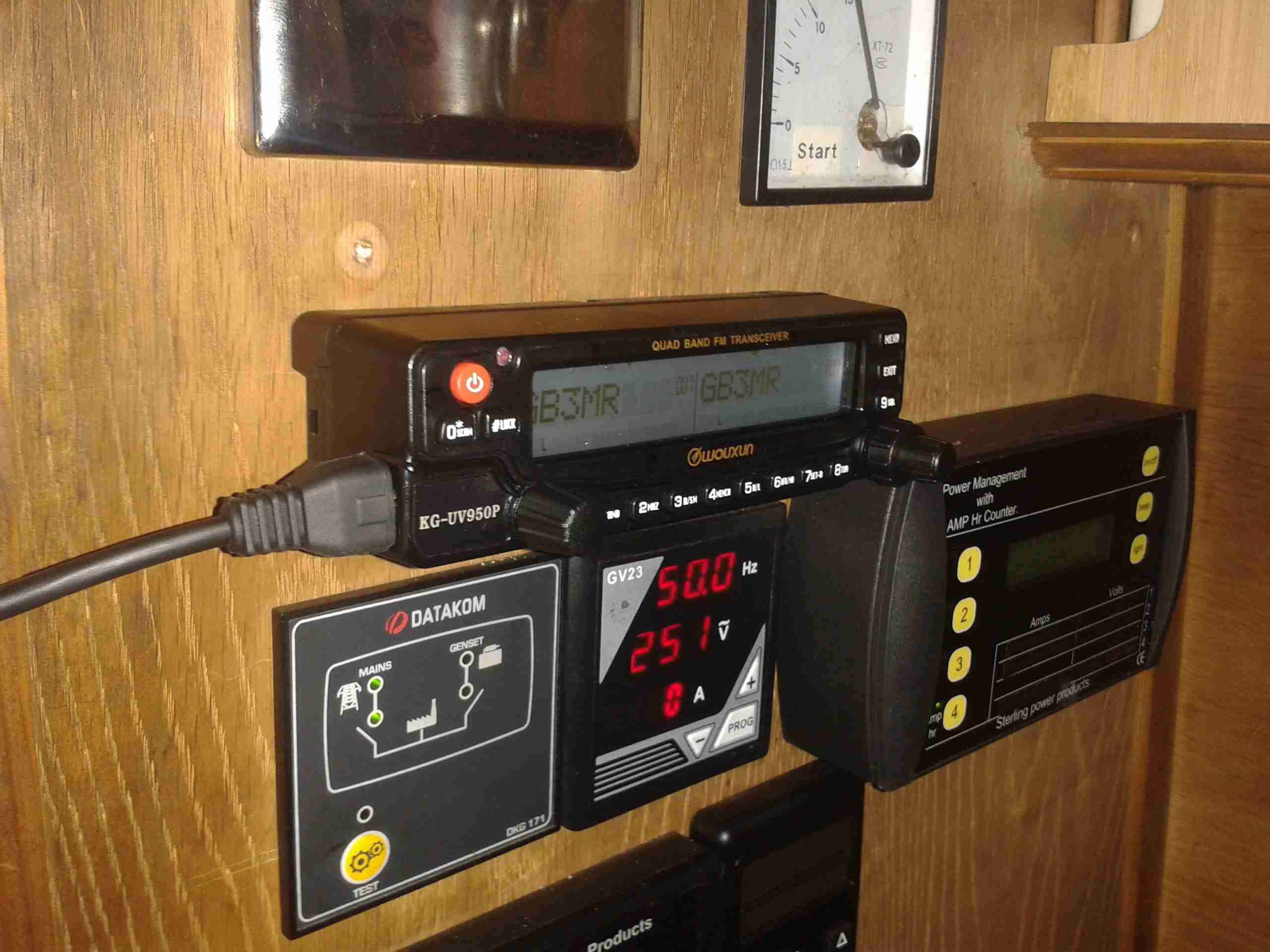
Radio Face Plate
Finally, the head unit is installed in a spot on the main panel. It does stick out a little more than I’d like, but it’s a lot of very dusty work with the router to make a nice hole to sink it further in. All my local repeaters & 2m/70cm simplex are programmed in at the moment.
Antenna Magmount
I’ve got a Nagoya SP-80 antenna on a magmount for the radio, a magmount being used due to the many low bridges & trees on the canal. (It’s on the roof next to the first solar panel above). I prefer it to just fall over instead of having the antenna bend if anything hits it!
Part 2 will be coming soon with details of the permanent antenna feeder.
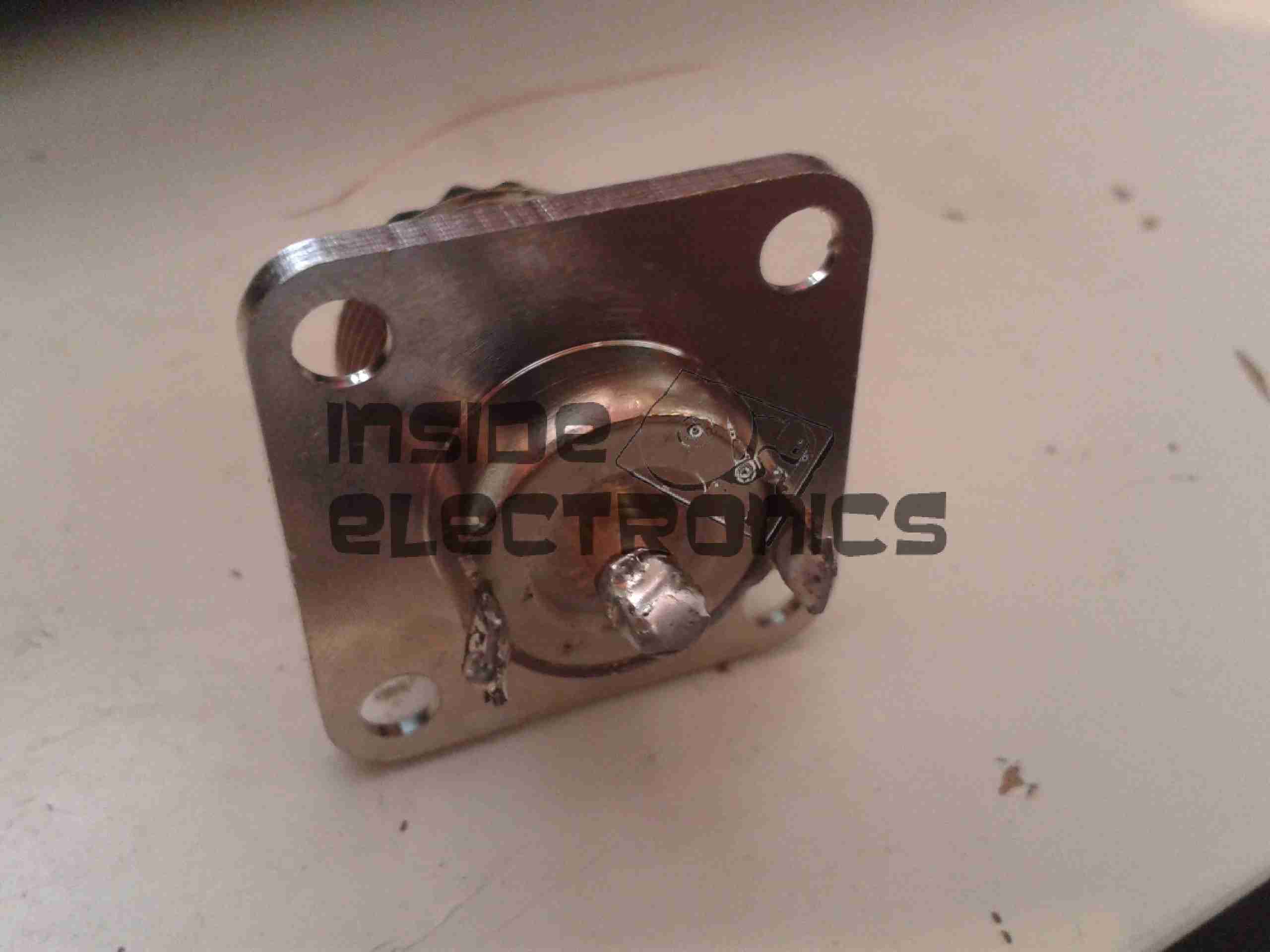
In my original review, I noted that this radio was supplied with a SO-259 socket for the antenna connection.
However I’m less than fond of these, due to their non-constant impedance, which can cause signal loss issues at VHF/UHF. Because of this, I’ve replaced it with a high quality N-type connector. These connectors are much better, as they are a constant 50Ω impedance, they’re weather resistant, and being rated to 11GHz, are more than sufficient for a radio that will only do up to 70cm.
RF Output Jack
Here can be seen the point where the connection is made to the PCB.
I’ve already replaced the socket in this photo. The pair of solder pads either side of the central RF point were soldered to wings on the back of the original SO-259. As there are a pair of screws, also connected to the ground plane, there have been no signal issues with just using the frame of the radio as the ground point. Shown below is the original socket, with the ground wings.
Original SO-259
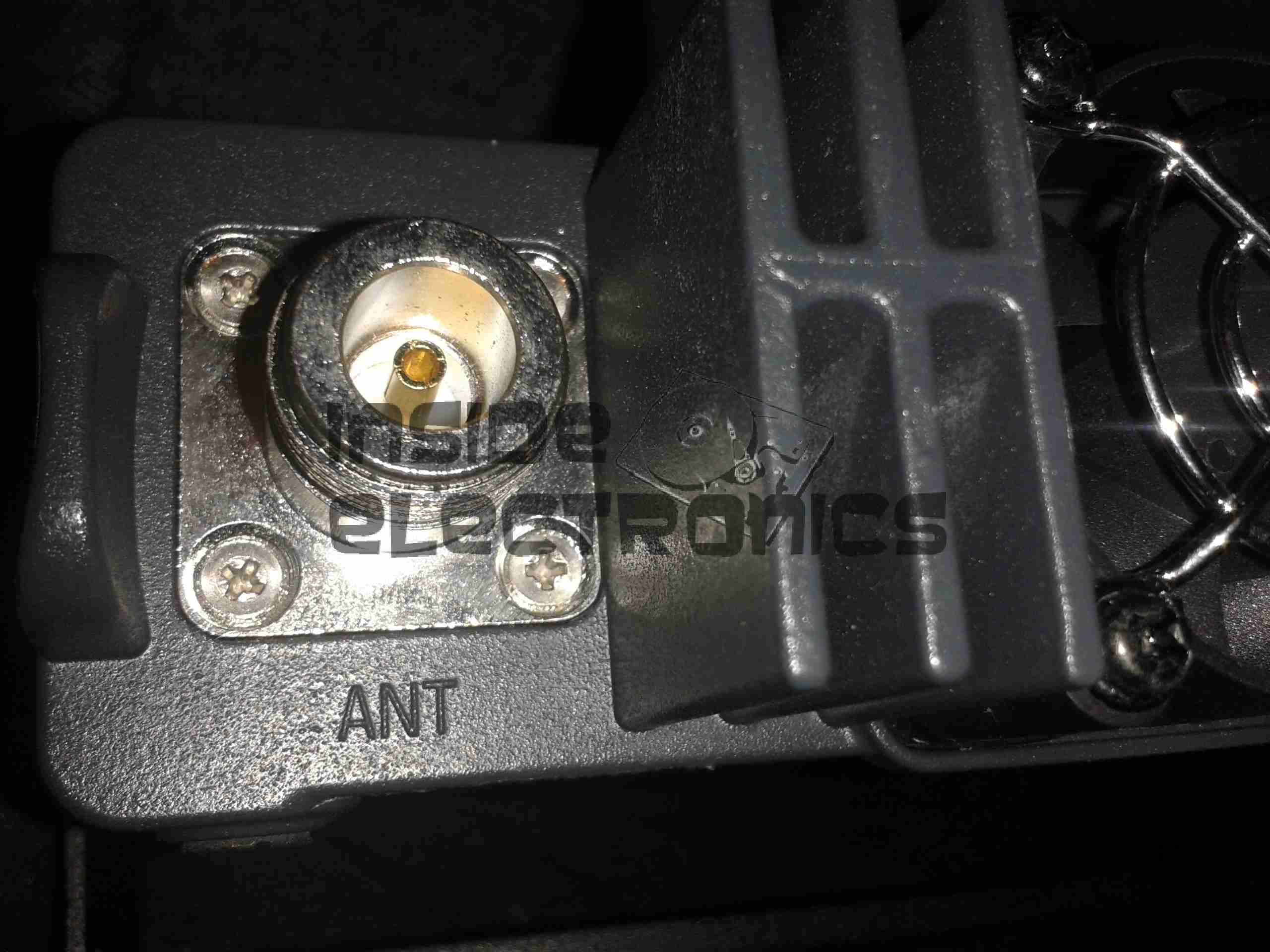
Finally, here is the back of the radio with it’s shiny new N connector.
New Connection
Chassis mount connectors are pretty standard, so this new connector fits perfectly into the same recess of the original. Looks like factory fitted!
I am now standardising on N connectors for everything in my radio shack, next on the project list for conversion is the SWR meter I recently acquired.
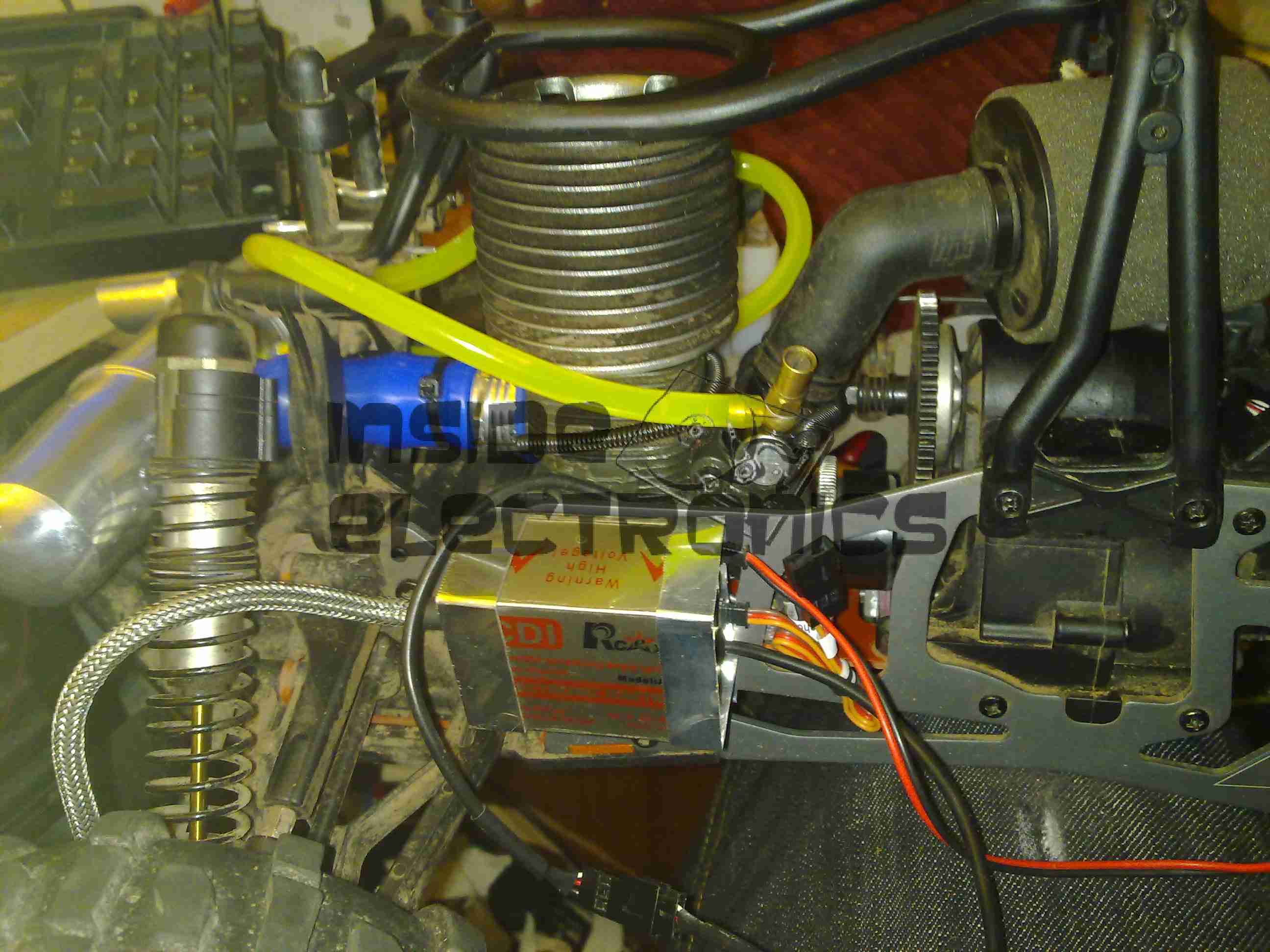
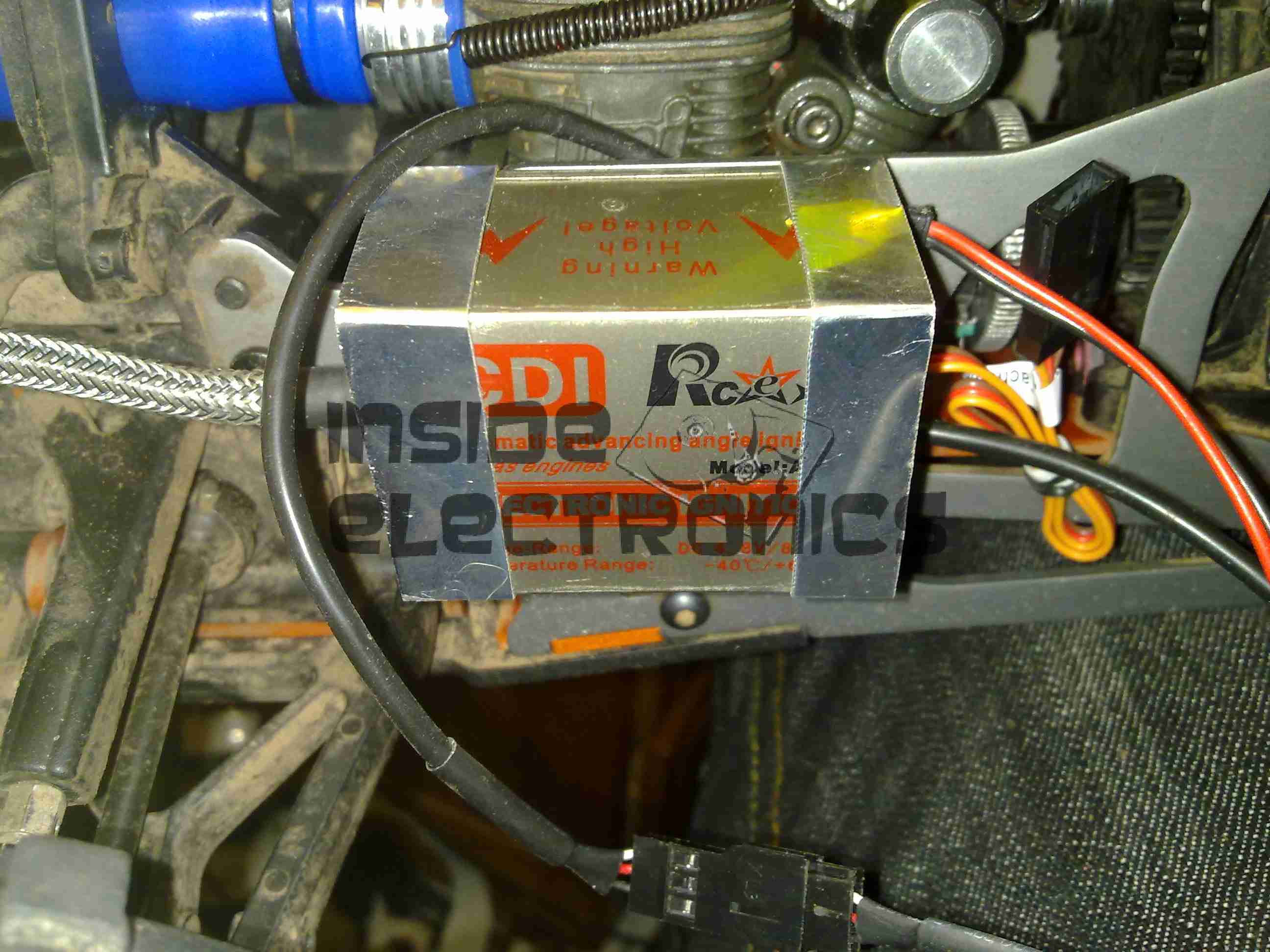
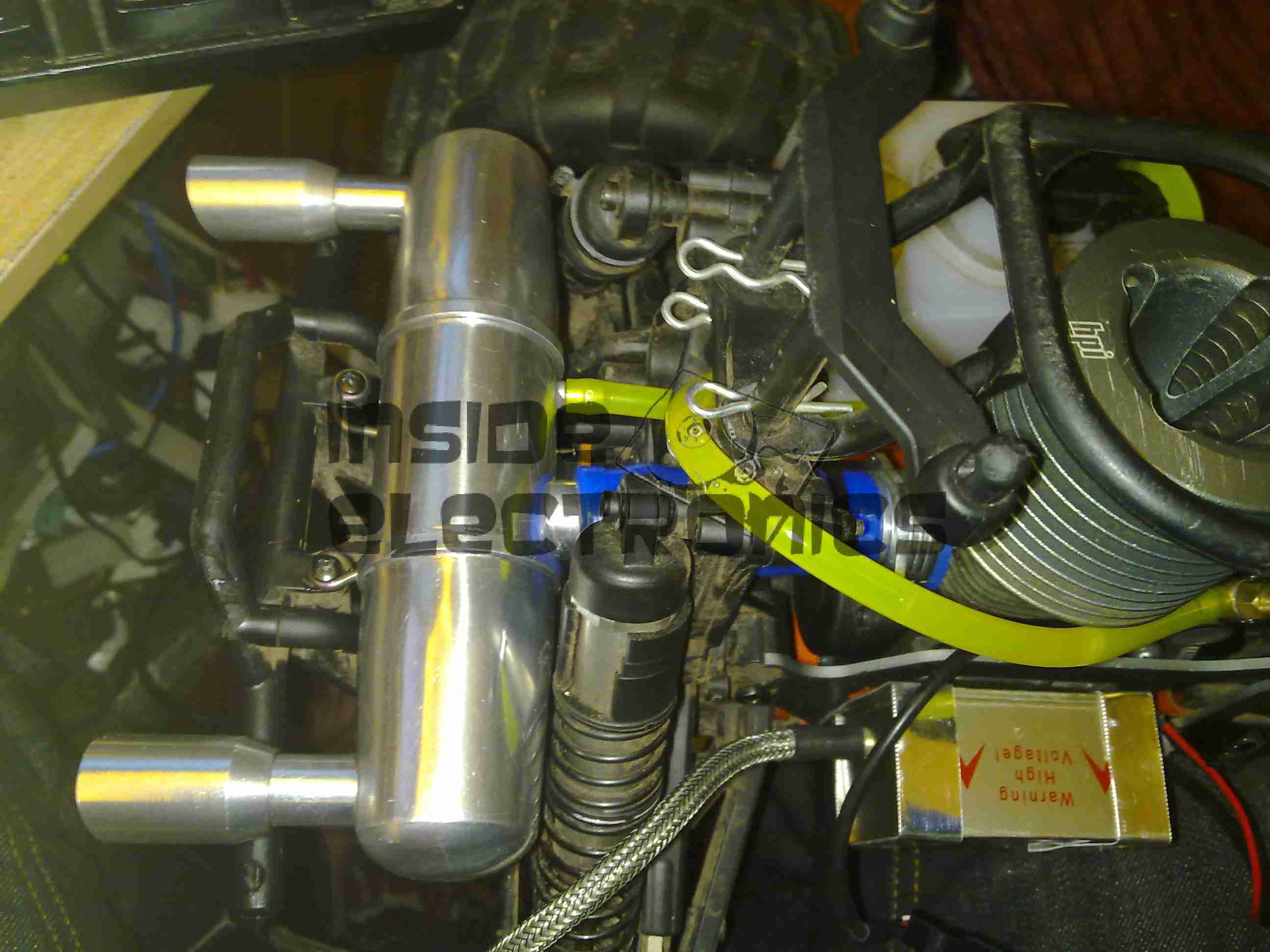
The engine now with it’s required ignition sensor, it is now mounted back on the chassis of the model. I have replaced the stock side exhaust with a rear silencer, so I could fit the ignition module in place next to the engine.
For the mounting, I fabricated a pair of brackets from 0.5mm aluminium, bent around the module & secured with the screws that attach the engine bed plate to the TVPs. The ignition HT lead can be routed up in front of the rear shock tower to clear all moving suspension parts, with the LT wiring tucked into the frame under the engine.
In this location the module is within the profile of the model chassis so it shouldn’t get hit by anything in service.
Rear Exhaust
New exhaust silencer fitted to the back of the model. This saves much space on the side of the model & allows the oily exhaust to be discharged away from the back wheel – no more mess to wipe up.
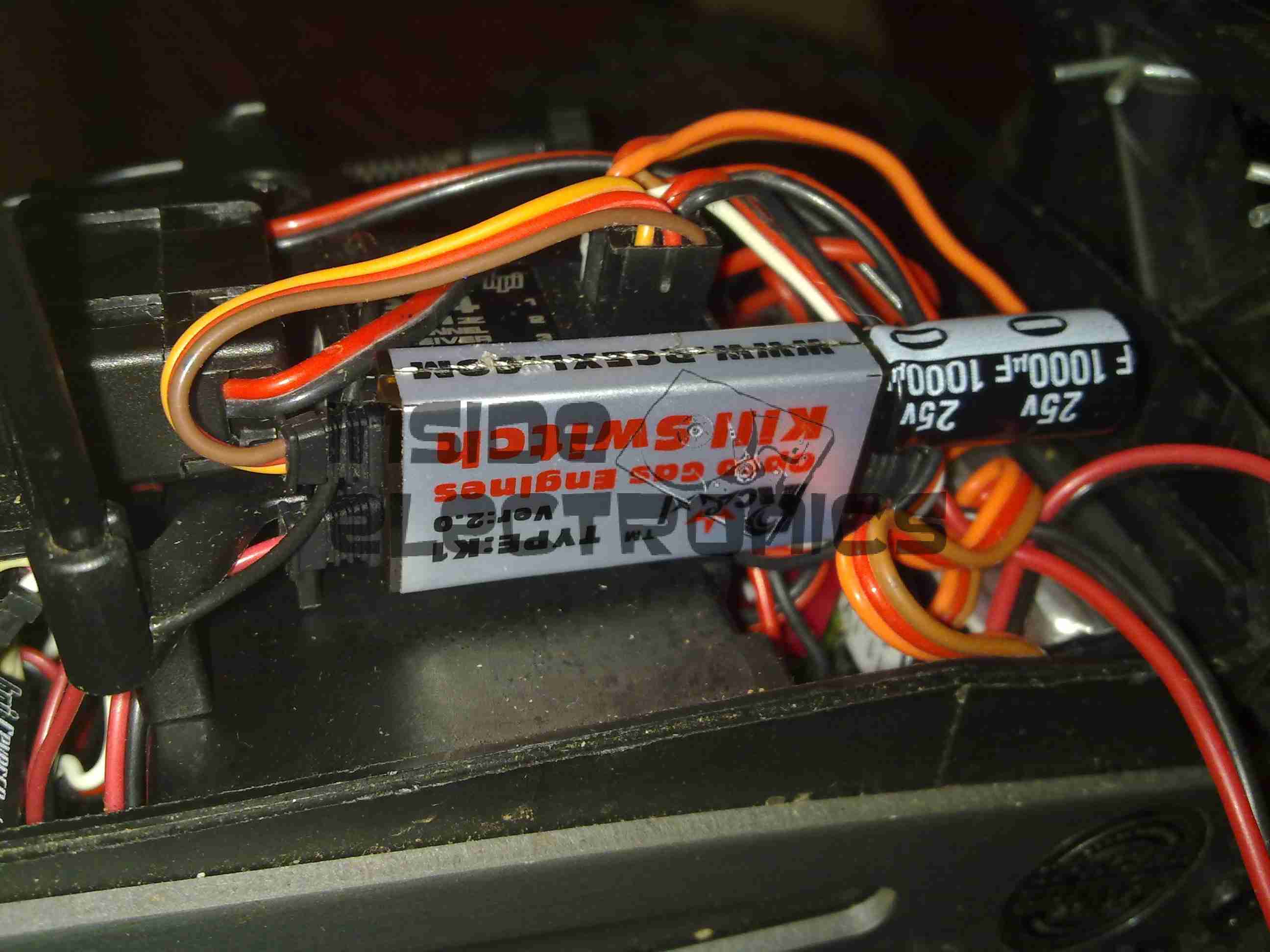
Kill Switch
The ignition switch fitted into the receiver box. This is wired into channel 3 of the TF-40 radio, allowing me to remotely kill the engine in case of emergency. I have fitted a 25v 1000µF capacitor to smooth out any power fluctuations from the ignition module.
The radio is running from a 11.1v 1Ah 3S LiPo pack connected to a voltage regulator to give a constant 6.5v for the electronics. I found this is much more reliable than the standard 5-cell Ni-MH hump packs.
Fuel Tank
The stock silicone fuel tubing has been replaced with Tygon tubing to withstand the conversion to petrol.
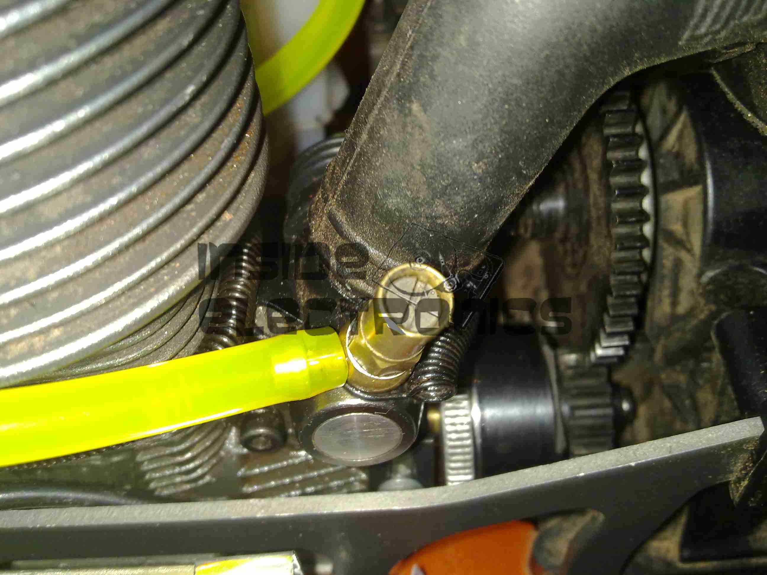
High Speed Needle
High speed needle tweaked to provide a basic running setting on petrol. This is set to ~1.5mm below flush with the needle housing.
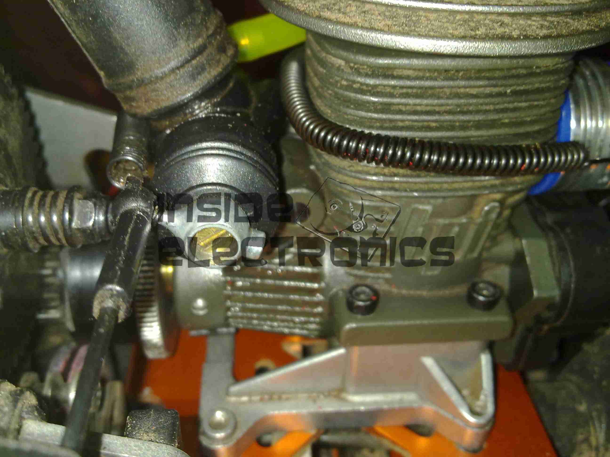
Low Speed Needle
Low speed needle tweaked to provide a basic running setting on petrol. This is set to ~1.73mm from flush with the needle housing.
As petrol is a much higher energy density fuel, it requires much more air than the methanol glow fuel – ergo much leaner settings.
The settings listed should allow an engine to run – if nowhere near perfectly as they are still rather rich. It’s a good starting point for eventual tuning.
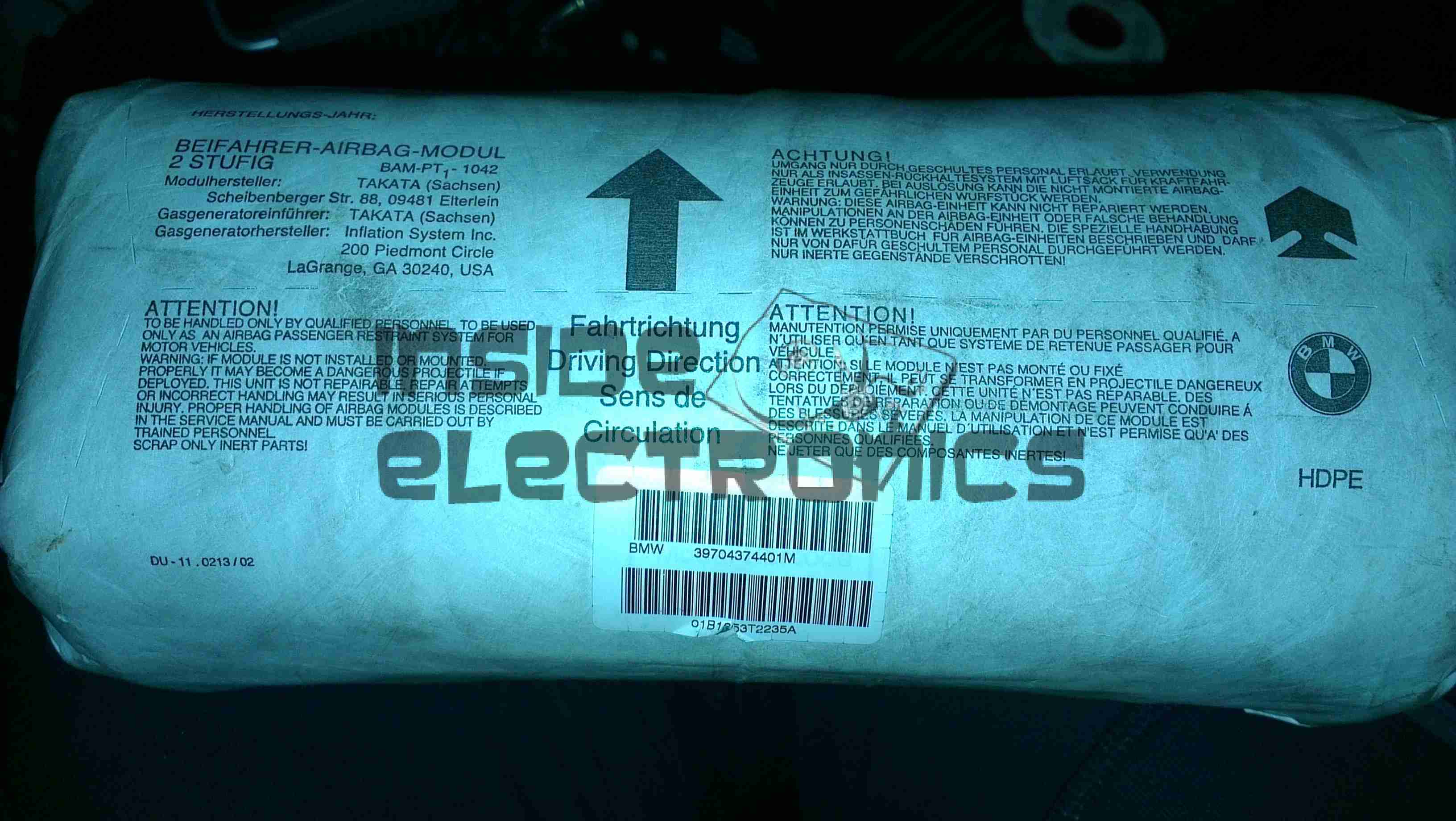
This is a passenger side airbag from a BMW vehicle. Here is the top of the device, with all the warning labels & information.
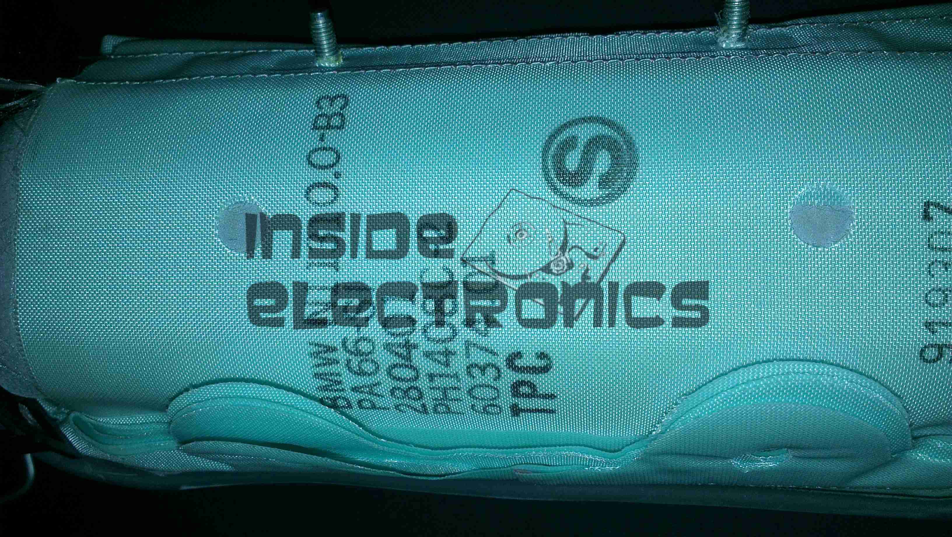
Folded Bag
Here the outer plastic wrap has been removed from the unit, showing the folded nylon fabric bag.
Frame
The base frame with the gas generator mounted.
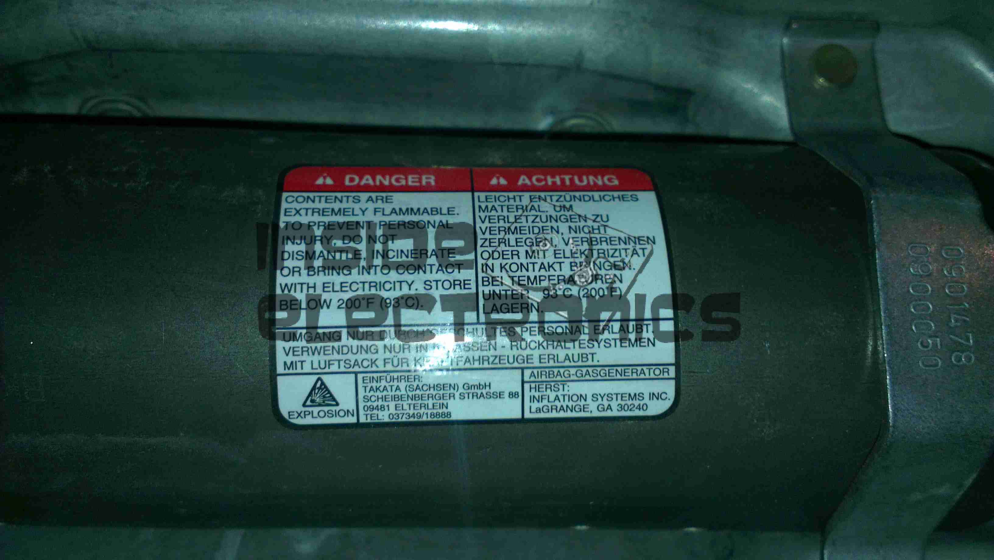
Gas Generator
Gas generator with warning label. This is a two part generator, with a pair of independent cores inside.
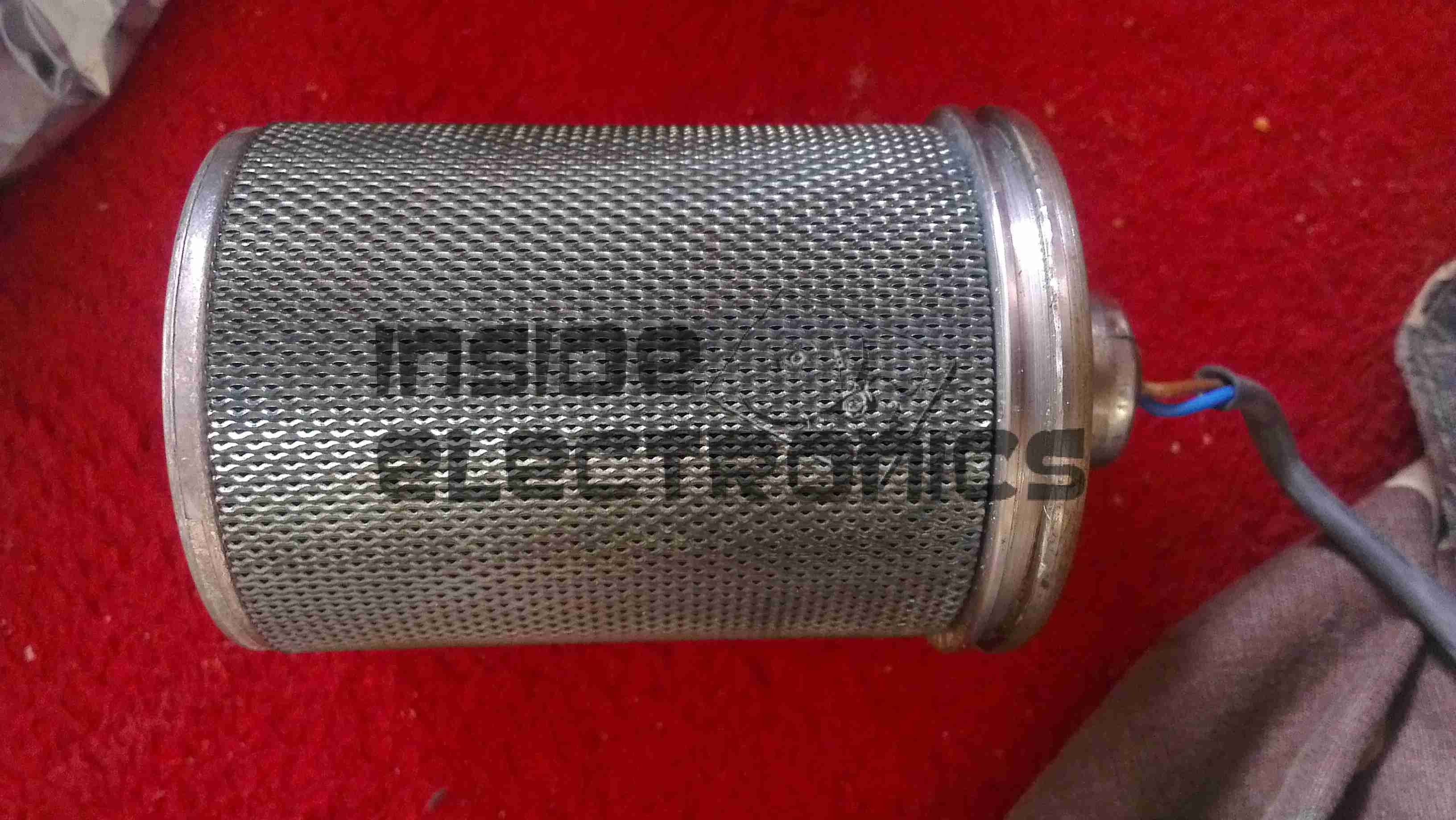
Generator Core
One of the generator cores removed from the heavy steel shell of the gas generator. The layers of wire mesh on the outside act as a flame trap, releasing only the gas generated from the burning propellant inside.
Propellant
End cap removed from the core, showing the pellets of propellant & the many layers of mesh & fibreglass filter material. The explosive initiator is in the bottom of this unit. A spring under the end cap firmly holds the pellets against the initiator.
Initiator
Finally, here is the explosive initiator that is located in the bottom of the core under the propellant pellets. This consists of a primary explosive & an electric match, which can be seen below as the device is disassembled.
Here’s the teardown of the projector itself! On the right is the info label from the projector, which covers the flex ribbon to the VGA/composite input board below.
This unit is held together with Allen screws, but is easy to get apart.
PicoP Display Engine
Here’s the insides of the projector, with just the top cover removed. The main board can be seen under the shielding can, the Micro HDMI connector is on the left & the MicroUSB connection is on the right. The USB connection is solely for charging the battery & provides no data interface to the unit.
On top of the main board is the shield can covering the PicoP Display Engine driver board, this shield was soldered on so no peek inside unfortunately!
Laser Module
The laser module itself is in the front of the unit, the laser assemblies are closest to the camera, on the left is the Direct Doubled Green module, in the centre is the blue diode, and the red diode on the right. Inside the module itself is an arrangement of mirrors & beamsplitters, used to combine the RGB beams from the lasers into a single beam to create any colour in the spectrum.
Module Innards
Here is the module innards revealed, the laser mounts are at the top of the screen, the green module is still mounted on the base casting.
The three dichroic mirrors in the frame do the beam combining, which is then bounced onto the mirror on the far left of the frame, down below the MEMs. From there a final mirror directs the light onto the MEMs scanning mirror before it leaves through the output window.
A trio of photodiodes caters for beam brightness control & colour control, these are located behind the last dichroic turning mirror in the centre of the picture.
Green Module Cavity
This is inside the green laser module, showing the complexity of the device. This laser module is about the size of a UK 5p coin!
Green Module Labeled
And here on the left is the module components labelled.
Main PCB Top
Here is the main PCB, with the unit’s main ARM CPU on the right, manufactured by ST.
User buttons are along the sides.
Main PCB Bottom
Other side of the main board, with ICs that handle video input from the HDMI connector, battery charging via the USB port & various other management.
Here is a 2Gbit Fibre Channel transceiver from Cisco Systems in SFP module format.
Shield Removed
Here the shield has been removed from the bottom of the module (it just clips off). The bottom of the PCB can be seen, with the copper interface on the left & the rubber boots over the photodiode & 850 nm laser on the right.
PCB Bottom
Here the PCB has been completely removed from the frame, the fibre ends slide into the rubber tubes on the right.
PCB Top
Top of the PCB, showing the chipset. There are a pair of adjustment pots under some glue, next to the chipset, presumably for adjusting laser power & receive sensitivity. The laser diode & photodiode are inside the soldered cans on the right hand side of the board, with the optics required to couple the 850nm near-IR light into the fibre.
A 5 megapixel digital camera from Vivitar. Visible here is the lens, viewfinder & flash.
Back
Rear of the unit showing the LCD & user control buttons.
Cover Removed
Front frame removed showing some of the internals. Shutter assembly & lens in centre, battery compartment at left.
Rear Cover Removed
Rear frame removede, showing the LCD module & tactile switches.
LCD
LCD module removed from the PCB
Flash PCB
Flash PCB removed. Transformer is fed with the 4.5v from the 3 AA cells & steps it up to ~300v DC for the flash capacitor. A pulse transformer energizes an electrode next to the Xenon flash tube with ~5kV to ionize the gas.
Main PCB
Main PCB removed. Internal flash ROM & RAM IC visible above the SD card socket. USB connector is at the top right, next to the piezo buzzer.
CPU
Main processor on reverse side of the PCB.
Image Sensor
Closeup of the CMOS image sensor with the lens assembly removed.
This is a HP PhotoSmart 375 portable photo printer. With built in card reader, screen & PictBridge.
Top of the printer showing the UI Buttons & Screen.
Front
Front of the unit, card reader slots at the top, Pictbridge USB connector at top left. Paper out slot at bottom. Cartridge door is on the right.
Cartridge Door
Here the cartridge door is open. Takes HP 95 Tri-Colour Inkjet Cartridge.
Battery Compartment
Battery compartment on the bottom of the unit. A Li-Ion battery pack can be installed here for mobile photo printing.
Bottom Label
Specifications label.
USB + Power
Power adaptor & USB connection for PC use.
Paper Tray
Rear door opened. Showing the paper feed tray.
Paper Feeder
Rear door has been removed in this shot. Paper feed roller & platen roller can be seen here.
Rear Cover Paper Feeder
Paper holder attached to rear door.
Top Cover
Bottom of the top cover, with connections for the buttons & LCD panel.
Main PCB
This is the main PCB of the unit. Controls all aspects of the printer. CPU in center, card reader sockets are along bottom edge. various support circuitry surrounds the CPU.
Rear
Rear shell has been removed here. Showing the main frame & the carriage drive motor on the left.
Carriage Drive
Closeup of the carriage drive motor & timing belt system. All the motors in this printer are DC servo motors, not steppers.
Main Drive Motor
Main drive motor, feeds paper, drives rollers, operates cleaning mechanism for the inkjets.
Shaft Encoder
Mainshaft encoder. Main drive motor is bottom right hand side with timing belt drive.
CPU
Closeup of the CPU. This is a Phillips ARM chip, unknown spec.
Card Reader Sockets
Detail of the card reader sockets, this unit takes all current types of Flash memory card.
HP 95 Tri-color Inkjet Print Cartridge
Tip Jar
If you’ve found my content useful, please consider leaving a donation by clicking the Tip Jar below!
All collected funds go towards new content & the costs of keeping the server online.