There’s quite a nice desktop app for the new NanoVNA v2, NanoVNA-Qt. It’s released as an AppImage for Linux, but unfortunately there is no version to run on a Pi supplied. The version below is built to run on the latest version of Raspbian (as of writing this, 2020-05-27).
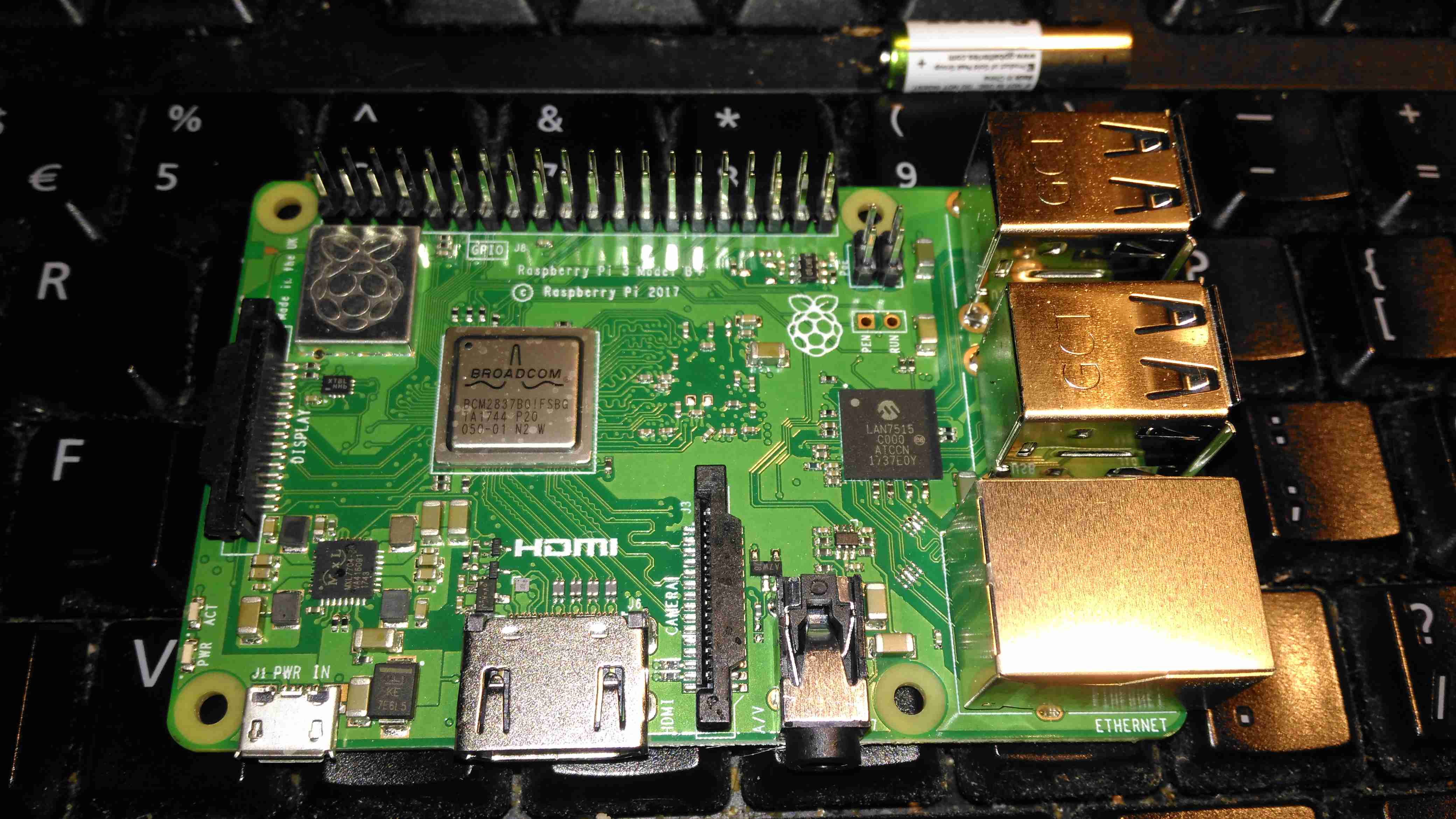
Yesterday, the Raspberry Pi community got a nice surprise – a new Pi! This one has some improved features over the previous RPi 3 Model B:
Improved CPU – 64-Bit 1.4GHz Quad-Core BCM2837B0
Improved WiFi – Dual Band 802.11b/g/n/ac. This is now under a shield on the top of the board.
Improved Ethernet – The USB/Ethernet IC has been replaced with a LAN7515, supporting gigabit ethernet. The backhaul is still over USB2 though, so this would max out at about 300Mbit/s
PoE Support – There’s a new 4-pin header, and a matching HAT for power over ethernet support.
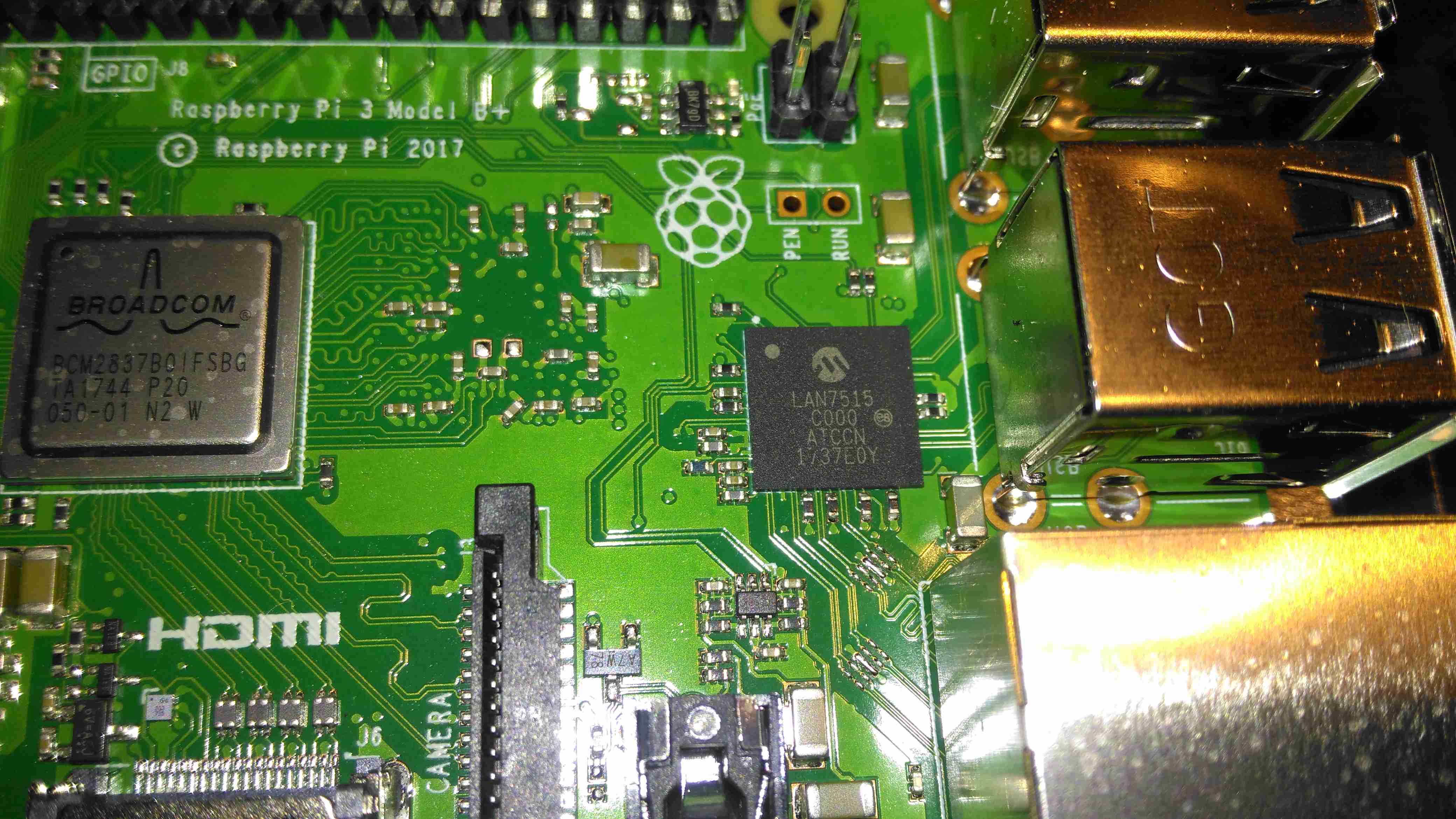
Chipset
The USB/LAN Controller is now a BGA package, supporting gigabit ethernet. The USB connections are still USB2 though, limiting total bandwidth. This shouldn’t be much of an issue though, since anything over the 100Mbit connection we’ve had previously is an improvement.
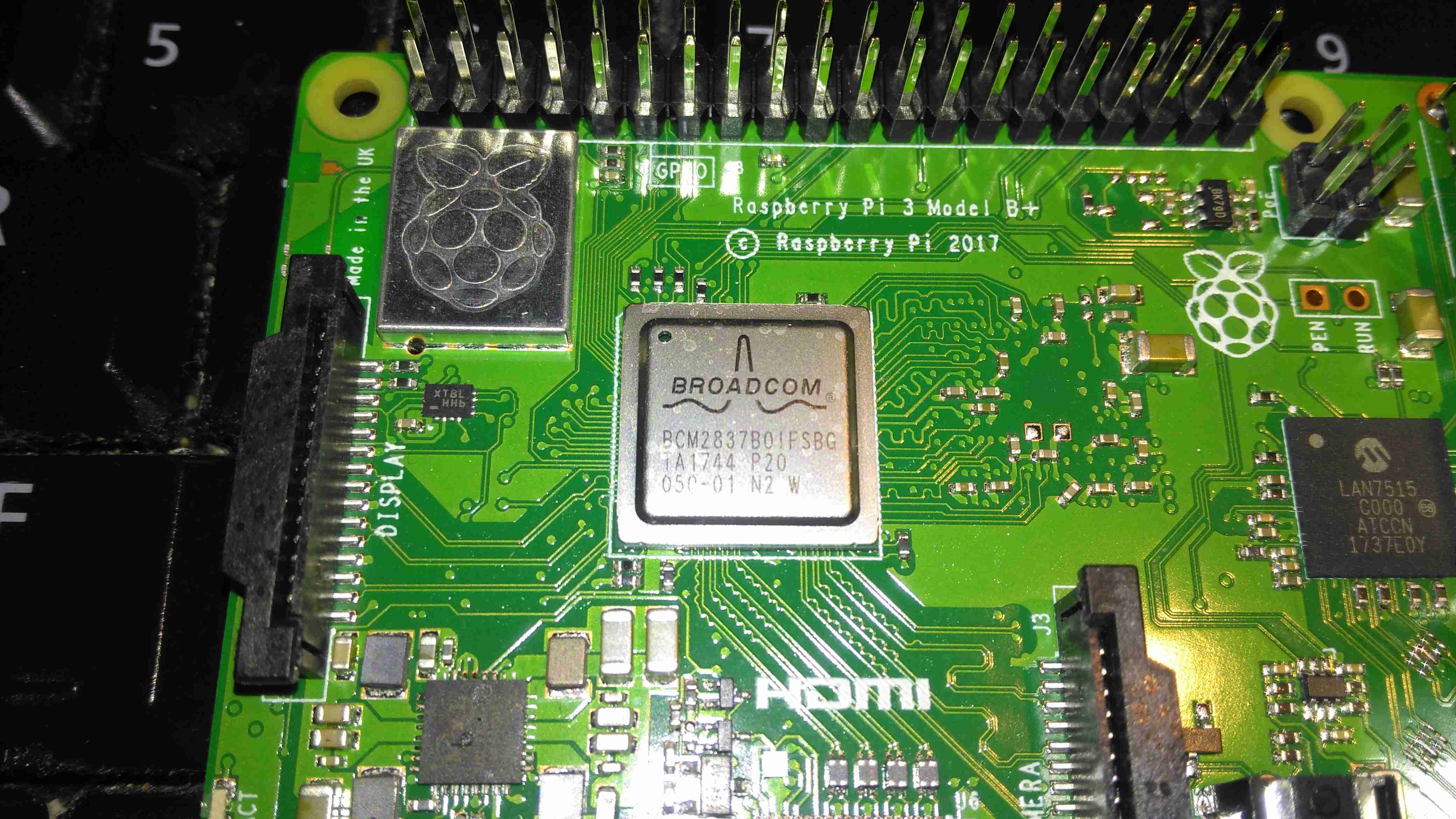
CPU & Radio
The CPU now has a metal heatspreader on top of the die, no doubt to help with cooling under heavy loads. As far as I know, it’s still the same silicon under the hood though. The WiFi radio is under the shielding can to the top left, with the PCB trace antenna down the left edge of the board.
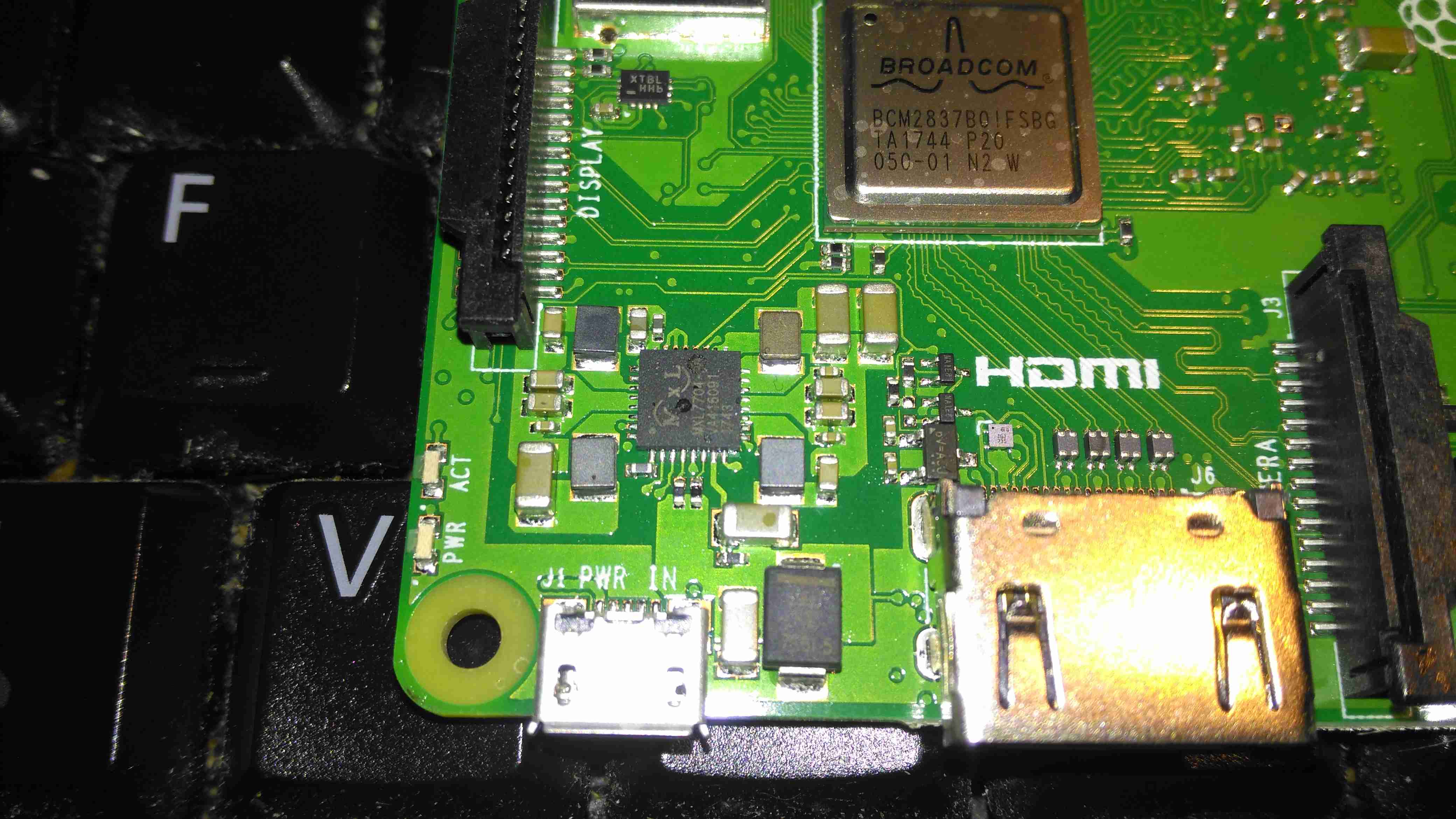
Power Controller
The power supplies are handled on this new Pi by the MaxLinear MxL7704, from what I can tell from MaxLinear’s page, it seems to be somewhat of a collaborative effort to find something that would do the best job, since they apparently worked with the Foundation to get this one right. This IC apparently includes four synchronous step-down buck regulators that provide system, memory, I/O and core power from 1.5A to 4A. An on-board 100mA LDO provides clean 1.5V to 3.6V power for analog sub-systems. This PMIC utilizes a conditional sequencing state machine that is flexible enough to meet the requirements of virtually any processor.
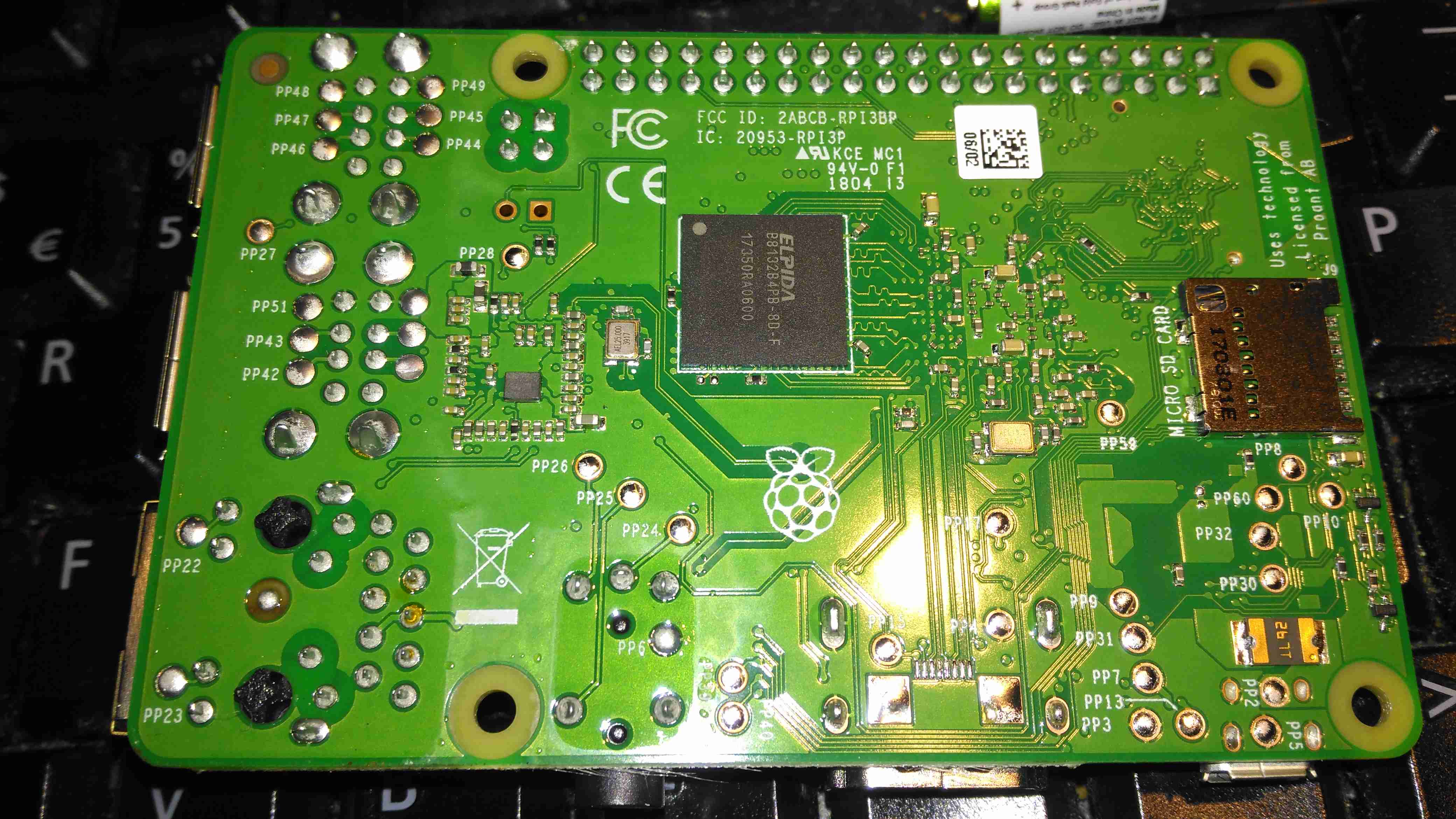
PCB Bottom
The bottom of the PCB has the Elpida 1GB RAM package, which is LPDDR2, along with the MicroSD slot.
A quick benchmark running Raspbian Lite & a SanDisk Ultra 32GB Class 10 SD card gives some nice results:
Since I’ve been working on the backend servers a lot over the past few days, I’ve decided it was time to get some broken things on the blog fixed.
Firstly, the radiation monitor graphs. Originally I was using a Raspberry Pi to grab the data from the local monitor, and that was connecting via FTP to the server over in the datacentre to push it’s graph images. Since the server is now on the same local network as the monitor, there’s no need to faff about with FTP servers, so I’ve rejigged things with some perl scripts from cristianst85 over on GitHub, running on the web server itself.
I deviated from the suggested place to put the scripts on the server & opted to store everything within the Experimental Engineering hosting space, so it gets backed up at the same time as everything else on a nightly basis.
This is also accessible from the menu at top left, the script pulls data from the monitor & updates the images every 60 seconds via a cron job.
I’ve removed a couple of dead pages from the blog system, along with some backend tidying of the filesystem. Over the years things have gotten quite messy behind the scenes. This blog is actually getting quite large on disk, I’ve hit the 15GB mark, not including the database!
Caching is enabled for all posts on the blog now, this should help speed things up for repeat visitors, but as most of my content is (large) image based, this might be of limited help. I’m currently tuning the MySQL server for the load conditions, but this takes time, as every time I change some configuration settings I have to watch how things go for a few days, before tweaking some more.
Server Control Panels – More Of The Same
Sorry Sentora. I tried, and failed to convert over to using it as my new server control panel. Unfortunately it just doesn’t give me the same level of control over my systems, so I’ll be sticking with Virtualmin for the foreseeable future. Sentora stores everything in, (to me at least), very odd places under /var/ and gave me some odd results with “www.” versions of websites – some www. hosts would work fine, others wouldn’t at all & just redirect to the Sentora login interface instead. This wasn’t consistient between hosting accounts either, and since I didn’t have much time to get the migration underway, this problem was the main nail in the coffin.
Just storing everything under the sun in /var/ makes life a bit more awkward with the base CentOS install, as it allocates very little space to / by default, (no separate /var partition in default CentOS), giving most of the disk space to /home. Virtualmin on the other hand, stores website public files & Maildirs under /home, saving /var for MySQL databases & misc stuff.
The backup system provided is also utterly useless, there’s no restore function at all, and just piles everything in the account into a single archive. By comparison, Virtualmin has a very comprehensive backup system built in, that supports total automation of the process, along with full automatic restore functionality for when it’s needed.
Sentora did have some good points though:
It handled E-Mail logins & mail filters much more gracefully than Virtualmin does, and comes with Roundcube already built into the interface ready to use. With Virtualmin the options are to use the Usermin side of the system for E-Mail, which I find utterly awful to use, or install a webmail client under one of the hosted domains (my personal choice).
Mail filtering is taken care of with Sieve under Sentora, while Procmail does the job under Virtualmin.
Sentora does have a nicer, simpler, more friendly interface, but it hides most of the low-level system stuff away, while under Virtualmin *everything* on the system is accessible, and it provides control interfaces for all the common server daemons.
As I’ve been posting some photos of decapped ICs lately, I thought I’d share the process I use personally for those that might want to give it a go 😉
The usual method for removing the epoxy package from the silicon is to use hot, concentrated Nitric Acid. Besides the obvious risks of having hot acids around, the decomposition products of the acid, namely NO² (Nitrogen Dioxide) & NO (Nitrogen Oxide), are toxic and corrosive. So until I can get the required fume hood together to make sure I’m not going to corrode the place away, I’ll leave this process to proper labs ;).
The method I use is heat based, using a Propane torch to destroy the epoxy package, without damaging the Silicon die too much.
TMS57002 Audio DSP
I start off, obviously, with a desoldered IC, the one above an old audio DSP from TI. I usually desolder en-masse for this with a heat gun, stripping the entire board in one go.
FLAMES!
Next is to apply the torch to the IC. A bit of practice is required here to get the heat level & time exactly right, overheating will cause the die to oxidize & blacken or residual epoxy to stick to the surface.
I usually apply the torch until the package just about stops emitting it’s own yellow flames, meaning the epoxy is almost completely burned away. I also keep the torch flame away from the centre of the IC, where the die is located.
Breathing the fumes from this process isn’t recommended, no doubt besides the obvious soot, the burning plastic will be emitting many compounds not brilliant for Human health!
Once the IC is roasted to taste, it’s quenched in cold water for a few seconds. Sometimes this causes such a high thermal shock that the leadframe cracks off the epoxy around the die perfectly.
All Your Die Belong To Us
Now that the epoxy has been destroyed, it breaks apart easily, and is picked away until I uncover the die itself. (It’s the silver bit in the middle of the left half). The heat from the torch usually destroys the Silver epoxy holding the die to the leadframe, and can be removed easily from the remaining package.
Decapped
BGA packages are usually the easiest to decap, flip-chip packages are a total pain due to the solder balls being on the front side of the die, I haven’t managed to get a good result here yet, I’ll probably need to chemically remove the first layer of the die to get at the interesting bits 😉
Slide
Once the die has been rinsed in clean water & inspected, it’s mounted on a glass microscope slide with a small spot of Cyanoacrylate glue to make handling easier.
Some dies require some cleaning after decapping, for this I use 99% Isopropanol & 99% Acetone, on the end of a cotton bud. Any residual epoxy flakes or oxide stuck to the die can be relatively easily removed with a fingernail – turns out fingernails are hard enough to remove the contamination, but not hard enough to damage the die features.
Once cleaning is complete, the slide is marked with the die identification, and the photographing can begin.
Microscope Mods
I had bought a cheap eBay USB microscope to get started, as I can’t currently afford a proper metallurgical microscope, but I found the resolution of 640×480 very poor. Some modification was required!
Modified Microscope
I’ve removed the original sensor board from the back of the optics assembly & attached a Raspberry Pi camera board. The ring that held the original sensor board has been cut down to a minimum, as the Pi camera PCB is slightly too big to fit inside.
The stock ring of LEDs is run direct from the 3.3v power rail on the camera, through a 4.7Ω resistor, for ~80mA. I also added a 1000µF capacitor across the 3.3v supply to compensate a bit for the long cable – when a frame is captured the power draw of the camera increases & causes a bit of voltage drop.
The stock lens was removed from the Pi camera module by careful use of a razor blade – being too rough here *WILL* damage the sensor die or the gold bond wires, which are very close to the edge of the lens housing, so be gentle!
Mounting Base
The existing mount for the microscope is pretty poor, so I’ve used a couple of surplus ceramic ring magnets as a better base, this also gives me the option of raising or lowering the base by adding or removing magnets.
To get more length between the Pi & the camera, I bought a 1-meter cable extension kit from Pi-Cables over at eBay, cables this long *definitely* require shielding in my space, which is a pretty aggressive RF environment, or interference appears on the display. Not surprising considering the high data rates the cable carries.
The FFC interface is hot-glued to the back of the microscope mount for stability, for handheld use the FFC is pretty flexible & doesn’t apply any force to the scope.
Die Photography
Since I modified the scope with a Raspberry Pi camera module, everything is done through the Pi itself, and the raspistill command.
Pi LCD
The command I’m currently using to capture the images is:
raspistill -ex auto -awb auto -mm matrix -br 62 -q 100 -vf -hf -f -t 0 -k -v -o CHIPNAME_%03d.jpg
This command waits between each frame for the ENTER key to be pressed, allowing me to position the scope between shots. Pi control & file transfer is done via SSH, while I use the 7″ touch LCD as a viewfinder.
The direct overhead illumination provided by the stock ring of LEDs isn’t ideal for some die shots, so I’m planning on fitting some off-centre LEDs to improve the resulting images.
Image Processing
Obviously I can’t get an ultra-high resolution image with a single shot, due to the focal length, so I have to take many shots (30-180 per die), and stitch them together into a single image.
For this I use Hugin, an open-source panorama photo stitching package.
Hugin
Here’s Hugin with the photos loaded in from the Raspberry Pi. To start with I use Hugin’s built in CPFind to process the images for control points. The trick with getting good control points is making sure the images have a high level of overlap, between 50-80%, this way the software doesn’t get confused & stick the images together incorrectly.
Optimiser
After the control points are generated, which for a large number of high resolution images can take some time, I run the optimiser with only Yaw & Pitch selected for all images.
Optimising
If all goes well, the resulting optimisation will get the distance between control points to less than 0.3 pixels.
Panorama Preview
After the control points & optimisation is done, the resulting image can be previewed before generation.
Texas Instruments TMS67002
After all the image processing, the resulting die image should look something like the above, with no noticeable gaps.
To cap off the series of scripts for doing easy timelapse video on the Raspberry Pi, here’s a script to generate a H.264 video from the images.
[snippet id=”1771″]
This should be run on a powerful PC rather than the Pi – generating video on the Pi itself is likely to be very slow indeed.
I have also done a quick update to the timelapse generator script to generate images of the correct size. This helps save disk space & the video generation doesn’t have to resize the images first, saving CPU cycles.
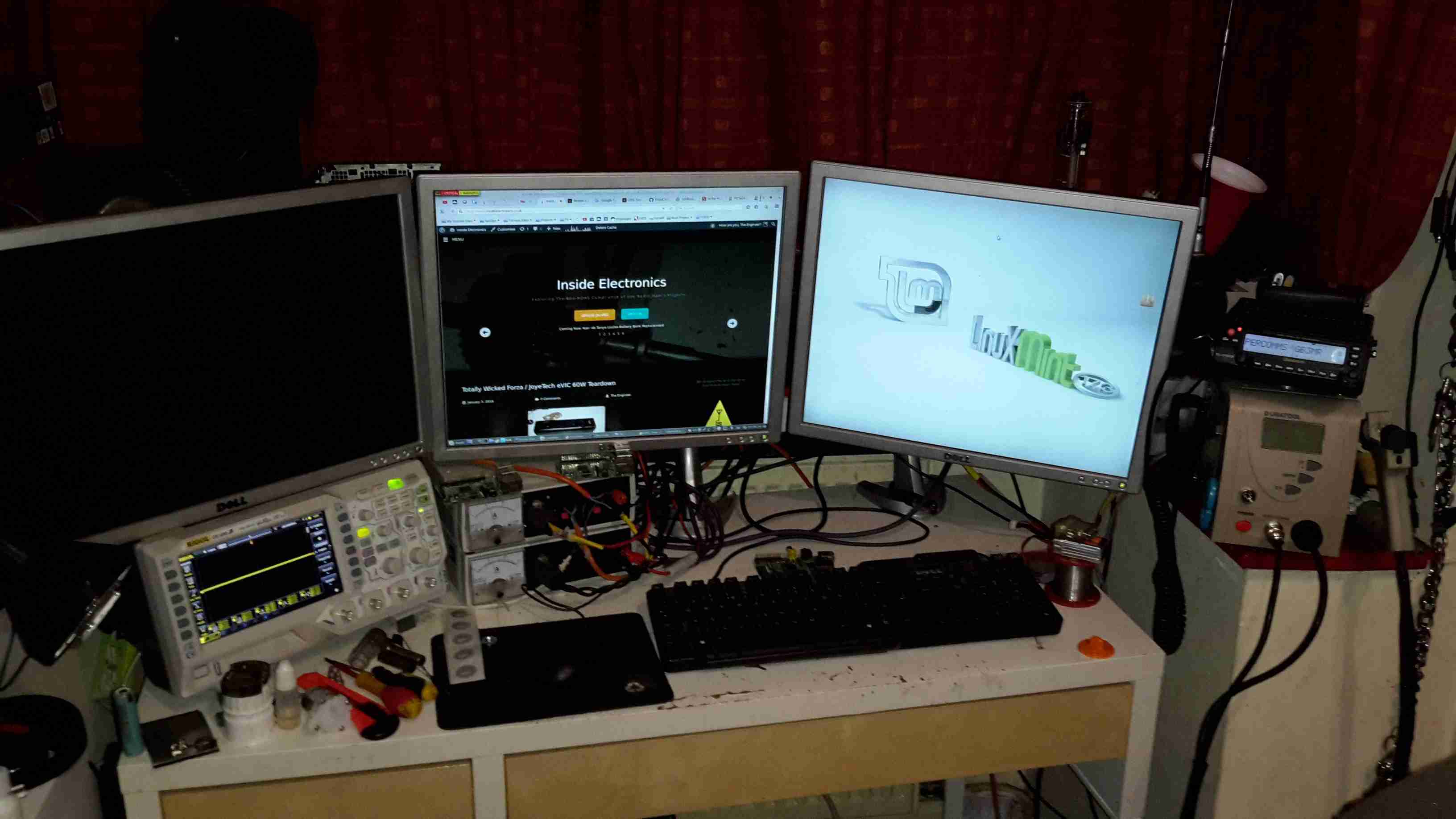
Main radio of course is housed on the left, it’s partially hidden under my currently over-populated breadboard.
All 3 monitors are linked to the same PC, using a pair of video cards. This is a very flexible system with so much screen real estate.
Main system power is provided by the pair of power supplies next to the radio – these are homebrew units using surplus switched mode PSU boards. Check my previous posts for more details.
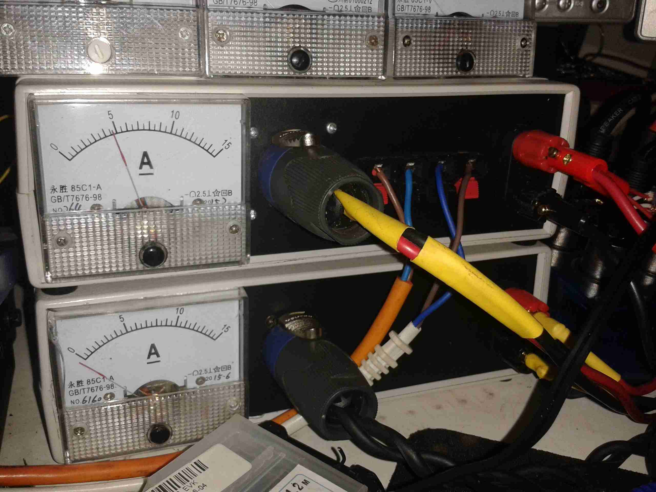
Power Supplies
The mainpowersupply system. These two supplies are cross connected, giving a total DC amperage of 30A at 13.8v. There is also a link to a large 220Ah lead-acid battery bank (orange cable), to keep me on the air during power outages. This cable is getting upgraded to something more beefy shortly. The white cable is currently supplying power to my onlineradiation monitor.
The main high-currentDC outputs are the Speakon connectors next to the meters. The top one is powering the radio directly, the bottom is linked through to my 12v distribution box for lower current loads, such as the oscilloscope, audio amplifiers, tools, etc.
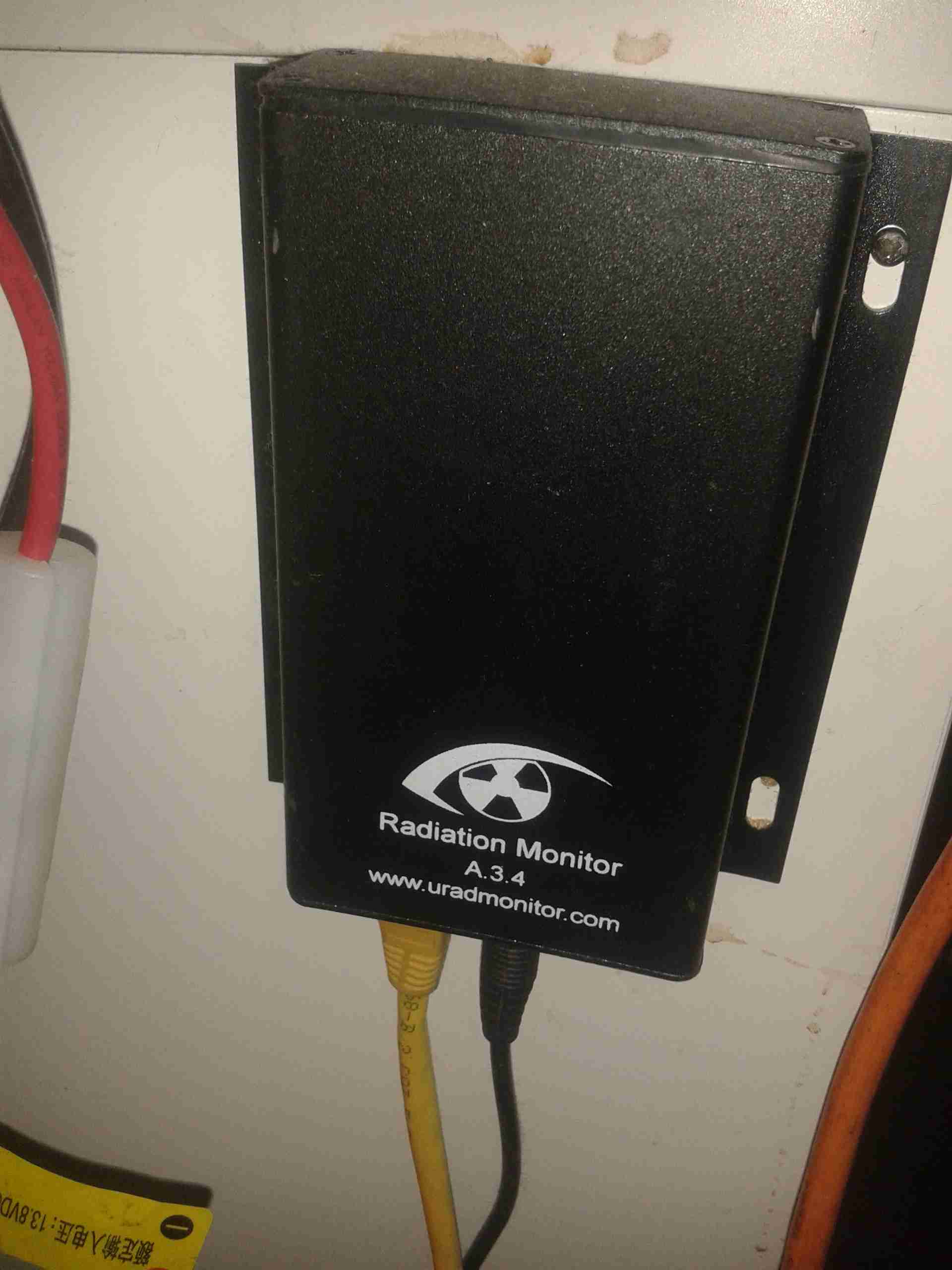
Radiation Monitor
Attached to the side of the desk is the radiation monitor itself.
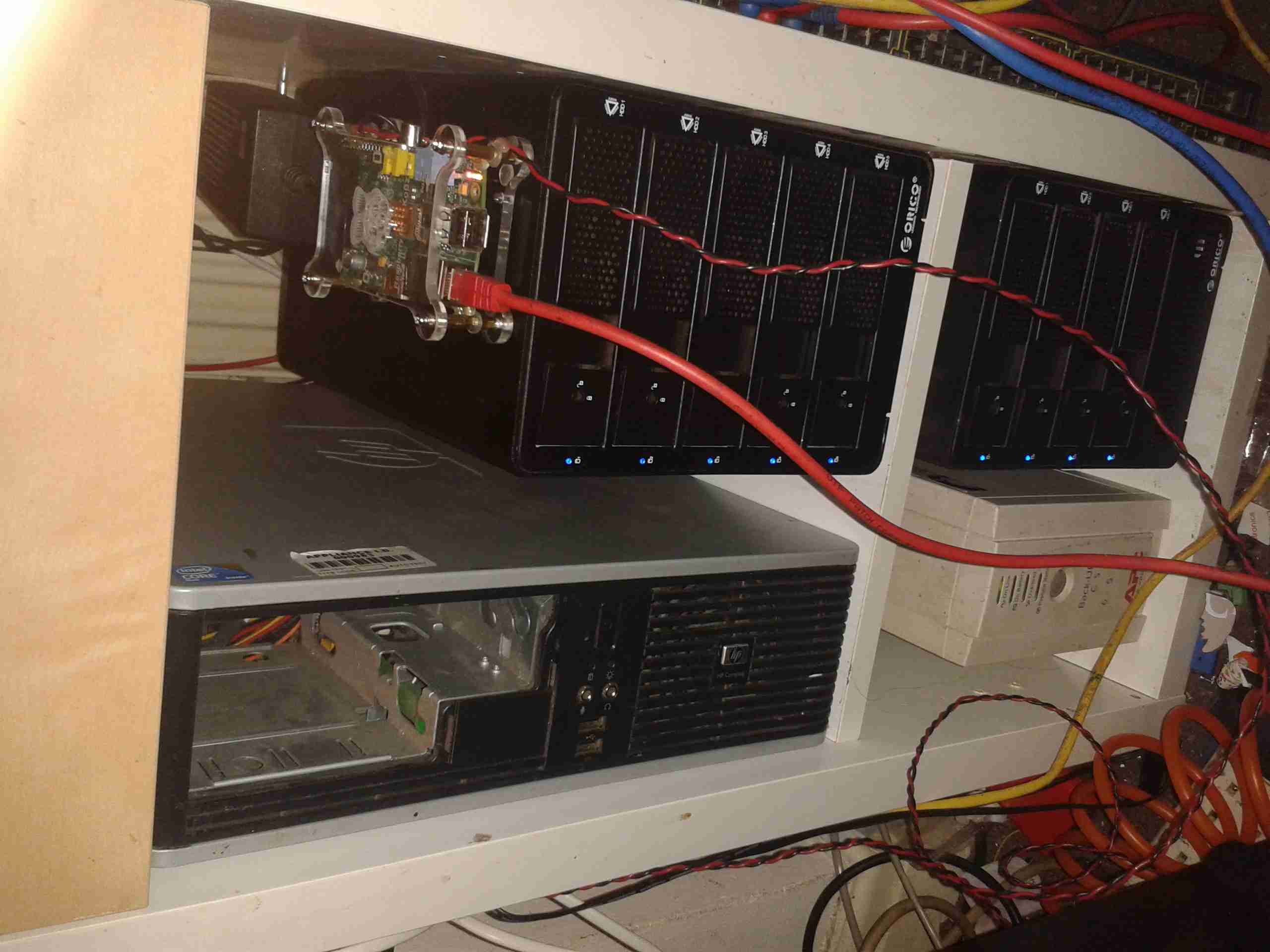
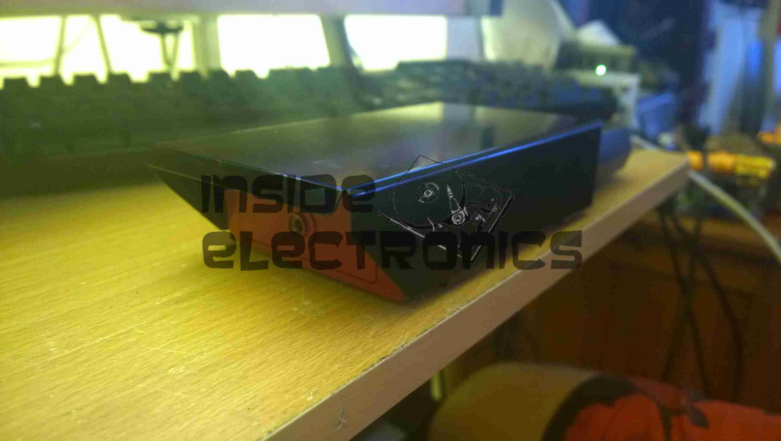
Core NAS
Under the radio is the core NAS of the network. It’s an array of 9 4TB disks, in RAID6, giving a total capacity after parity of 28TB. This provides storage & services to every other machine in the shack, the Raspberry Pi on top of the disk array is doing general network housekeeping & monitoring, also generating the graphs for the Radiation Monitor page. A Cisco 48-portswitch is partially out of frame on the right, providing 100MB Ethernet to the devices that don’t require gigabit.
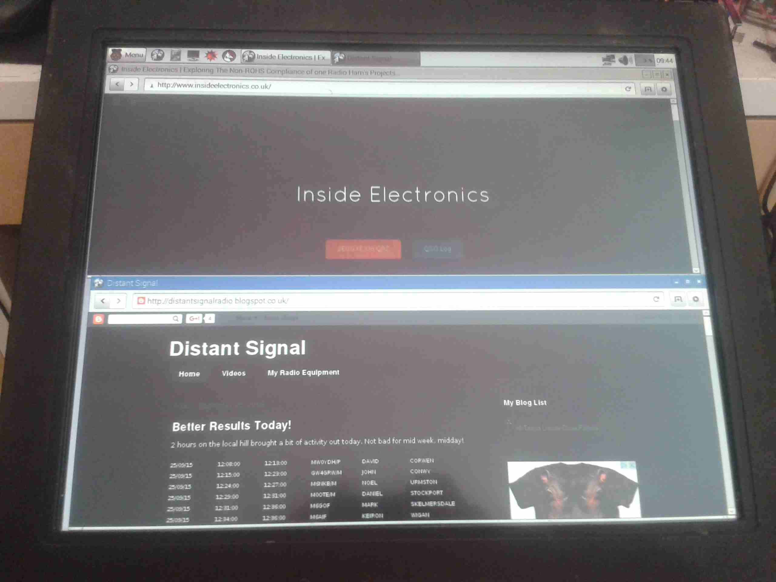
A while back I posted about a 3M Touch Systems industrial monitor that I’d been given. I had previously paired it with a Raspberry Pi Model B+, but for general desktop use it was just a little on the slow side.
Since the release of the Raspberry Pi 2, with it’s 4-core ARM Cortex CPU, things are much improved, so I figured I’d post an update with the latest on the system.
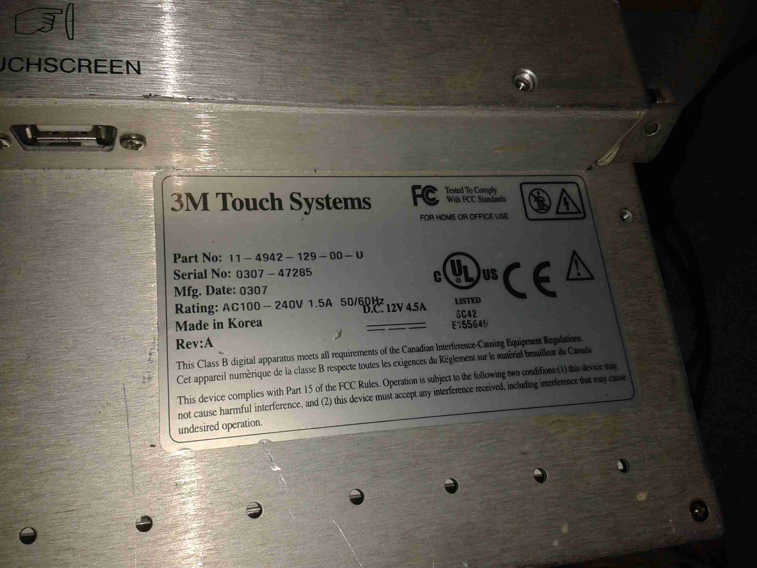
The monitor I’ve used is a commercial one, used in such things as POS terminals, service kiosks, etc. It’s a fairly old unit, but it’s built like a tank.
3M Panel
It’s built around a Samsung LTM170EI-A01 System-On-Panel, these are unusual in that all the control electronics & backlighting are built into the panel itself, instead of requiring an external converter board to take VGA to the required LVDS that LCD panels use for their interface.
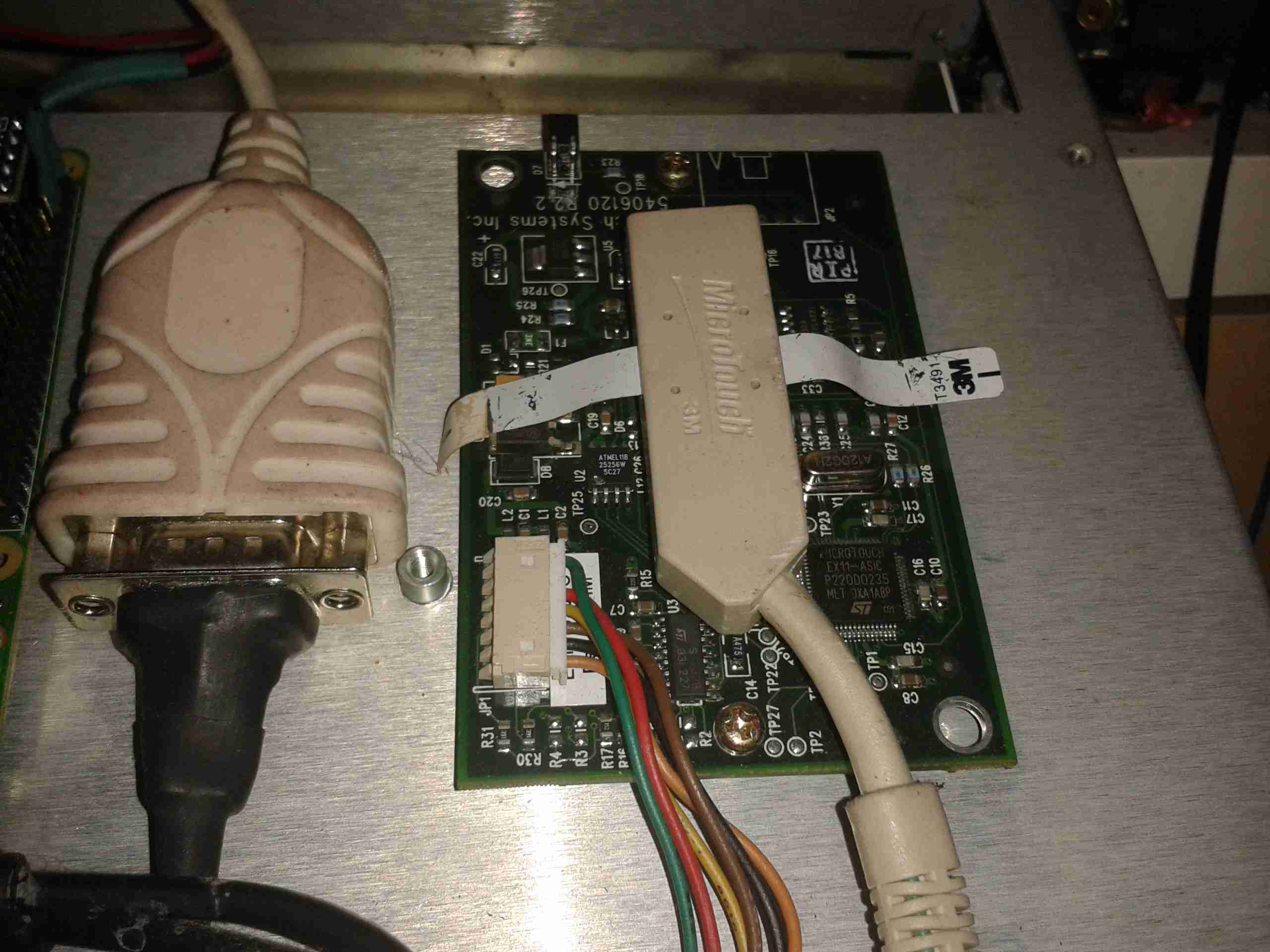
The touch section is a 3M Microtouch EXII series controller, with a surface capacitive touch overlay.
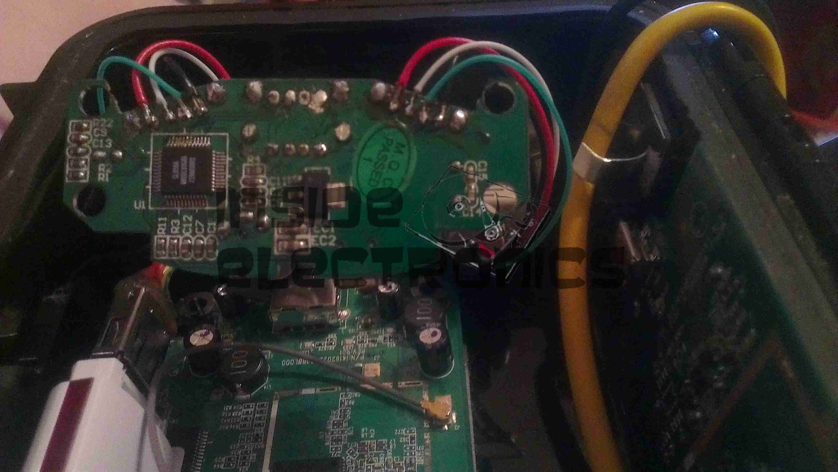
Touch Controller
Above is the touch controller PCB, with it’s USB-Serial converter to interface with the Pi.
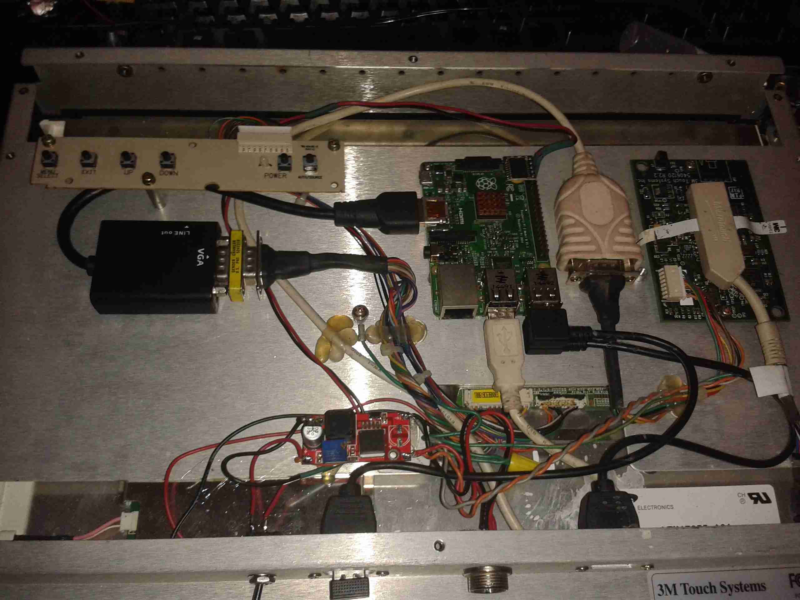
As there is much spare space inside the back of this monitor, I have mounted the Pi on a couple of spare screw posts, fitted USB ports where the original VGA & Serial connectors were in the casing, and added voltage regulation to provide the Pi with it’s required 5v.
Overview
Here’s the entire back of the panel, the Pi in the middle interfaces with a HDMI-VGA adaptor for the monitor, and the serial adaptor on the right for the touch. A small voltage regulator at the bottom of the unit is providing the 5v rail. There’s a switch at the bottom next to one of the USB ports to control power to the Pi itself. The panel won’t detect the resolution properly if they’re both powered on at the same time.
At 13.8v, the device pulls about 2A from the supply, which seems to be typical for a CCFL backlighted LCD.
Now the Raspberry Pi 2 has been released, it’s much more responsive for desktop applications, especially with a slight overclock.
Shameless Plug
A full disk image enabled for Desktop & 3M touch monitors is available below for others that have similar panels. This image only works for the Pi 2!
I’ve had a couple of viewfinder CRT modules for a while, & haven’t done much with them, so I decided to make a very small B&W monitor.
CRT
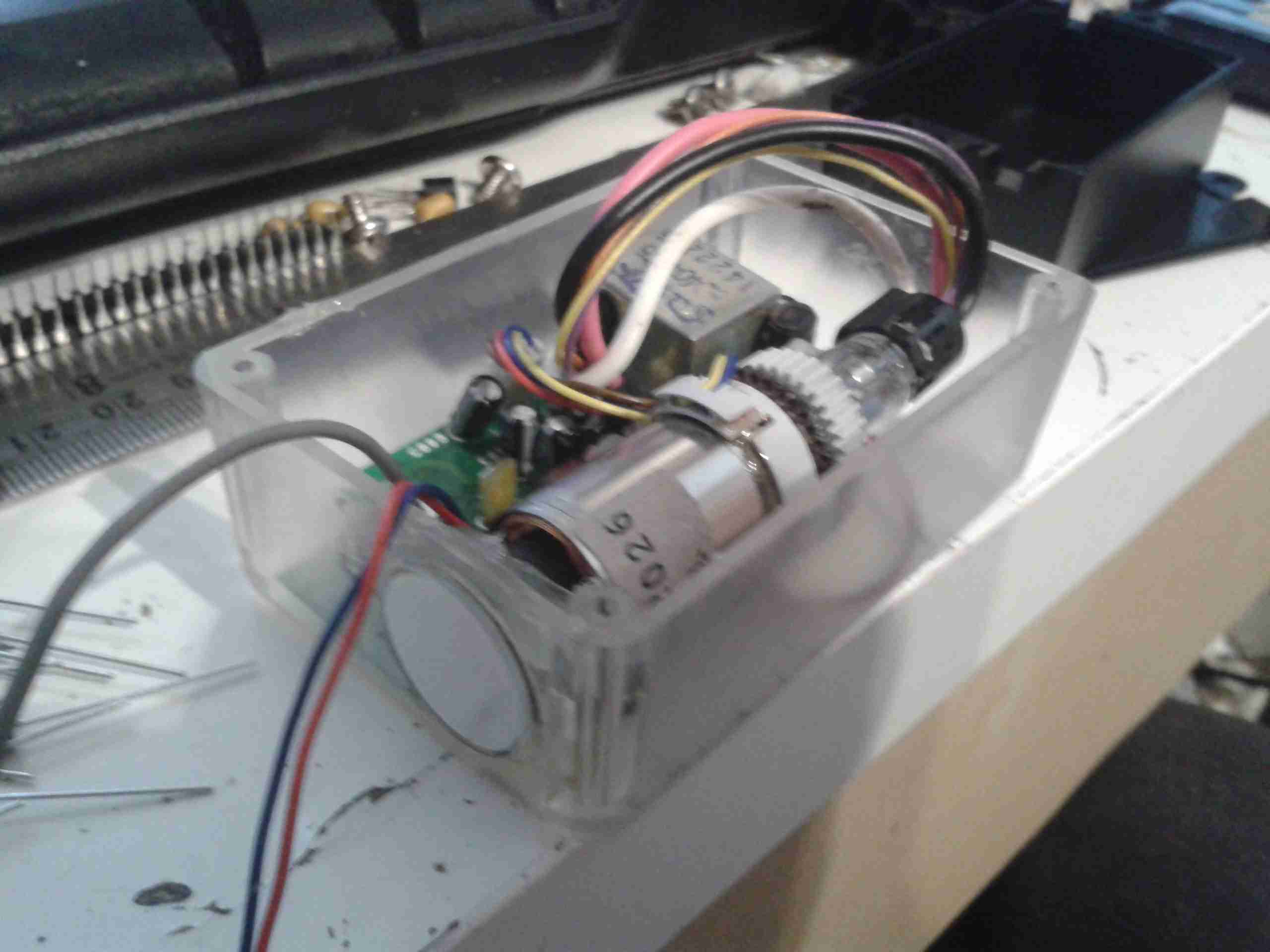
I ordered a small transparent ABS box when I made a large order with Farnell, that turned out to be just about the perfect size for the project! The CRT & PCB barely fit into the space. The face of the CRT itself is about 17mm across.
Module Installed
Here’s the main PCB & tube fully installed into the case. Barely enough room for a regulator left over!
Power is provided by a simple LM7809 IC to take a standard 12v input.
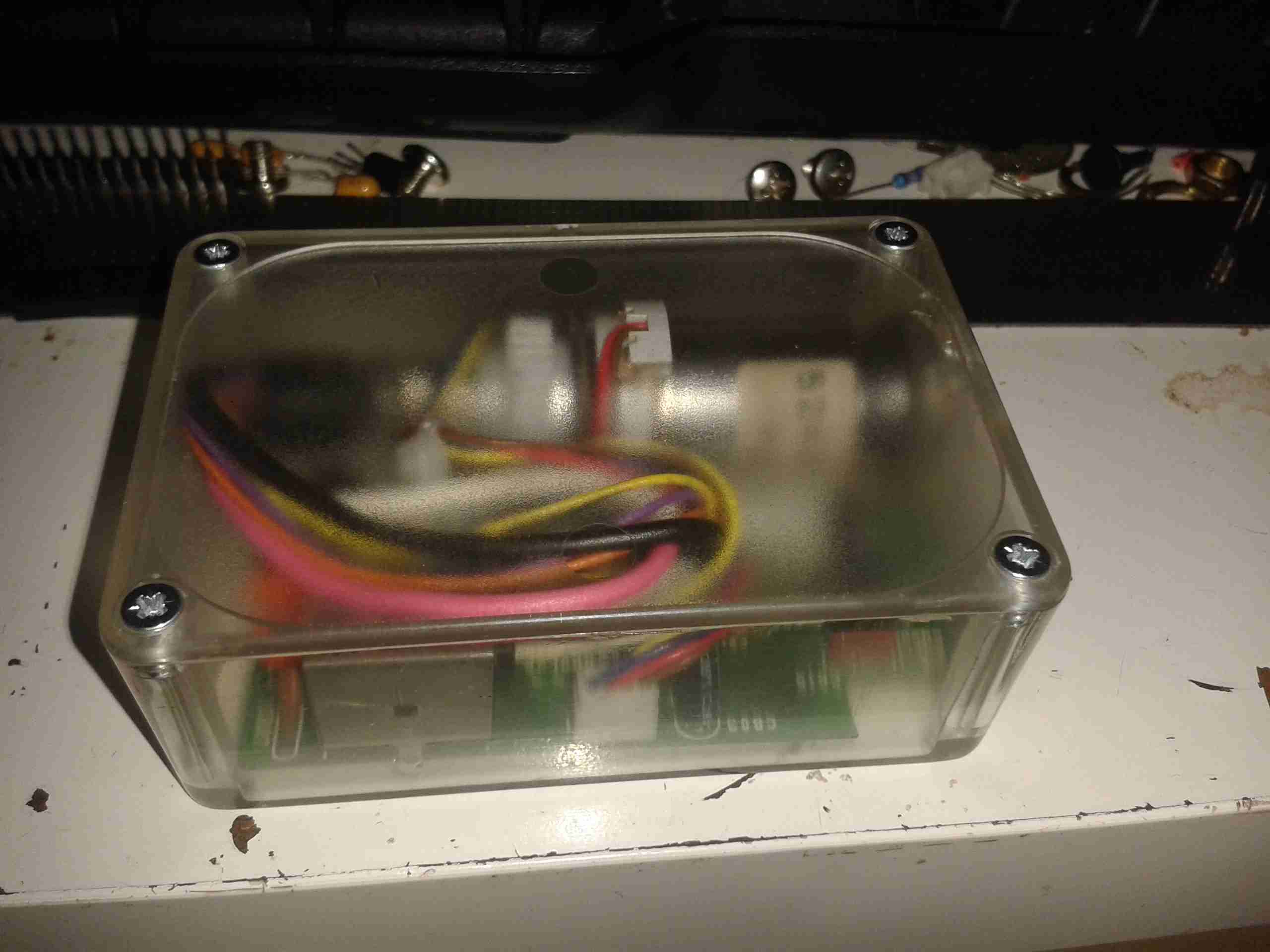
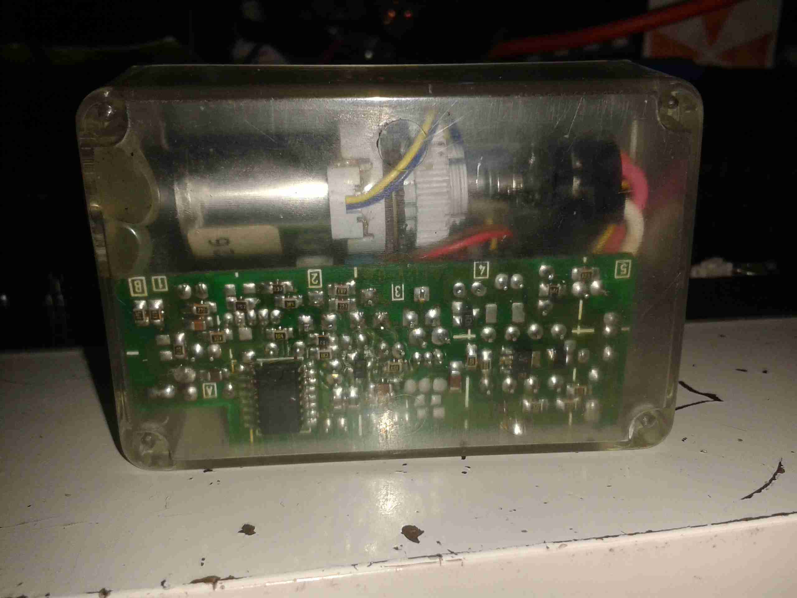
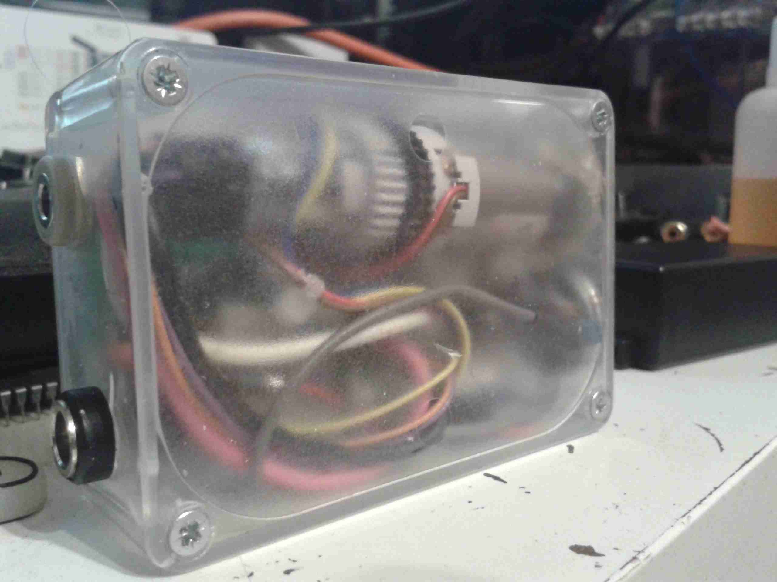
Module Rear
Rear of the case, showing the fit of the control board.
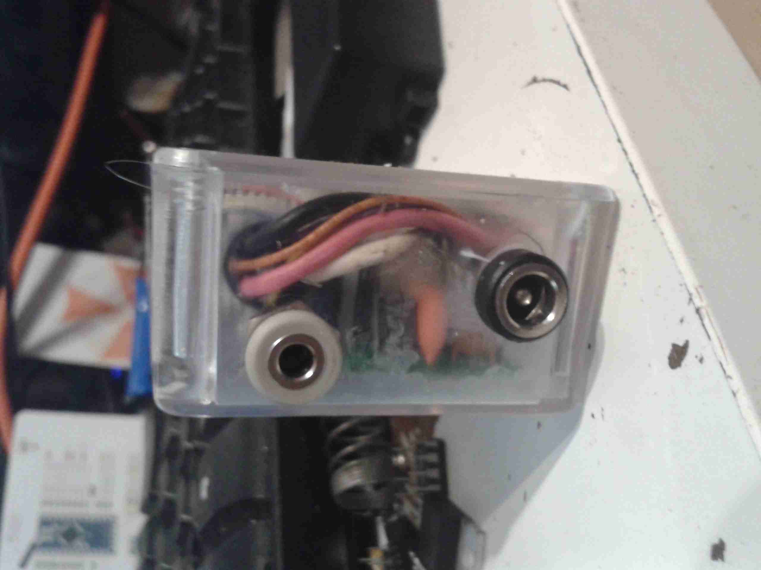
Connections
Here’s the back of the monitor, with the DC input jack & a 3.5mm 4-pole jack for audio & video. This allows simple connection to many devices, including the one I’ll use the most – the Raspberry Pi.
Completed
Completed monitor. Audio is handled by a very small 20mm speaker, currently mounted just below the CRT face.
Current draw from a 13.8v supply is 117mA.
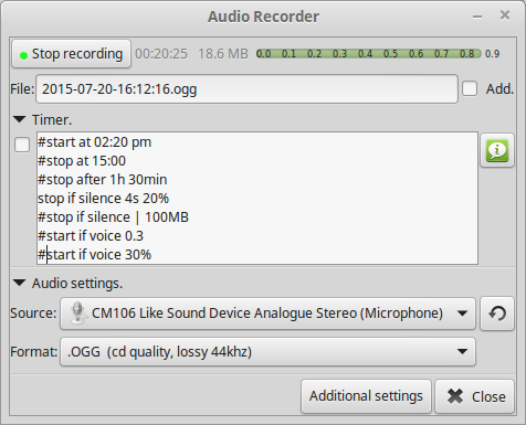
Since my new Wouxun has audio output jacks, I figured it would be useful to have the ability to record what my rig hears, if anything interesting comes on the air.
Under Linux, I use an application called, (creatively enough), Audio Recorder.
Recorder Screenshot
Using a simple connection to the mic input on a USB soundcard, I can capture everything the radio hears. Unfortunately this doesn’t work for outgoing audio, so it’s not much good at capture of my personal QSOs. For this I will have to set up another radio to act as the main receiver.
At some point in the future I will implement this with a Raspberry Pi as the audio capture server.
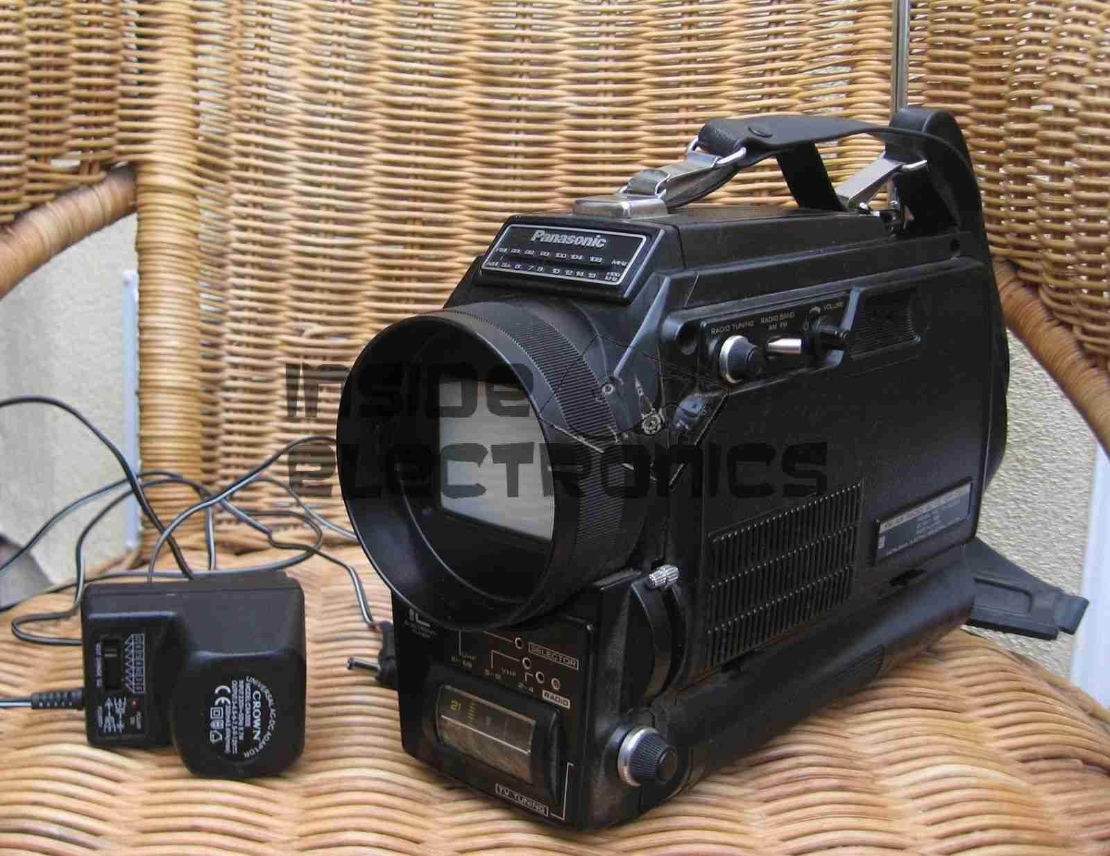
I recently managed to score a 3″ B&W portable TV on eBay, a Panasonic TR-3000G. As these old units are now useless, thanks to the switch off of analogue TV signalling, I figured I could find a composite signal internally & drive the CRT with an external source.
Panasonic TR-3000G
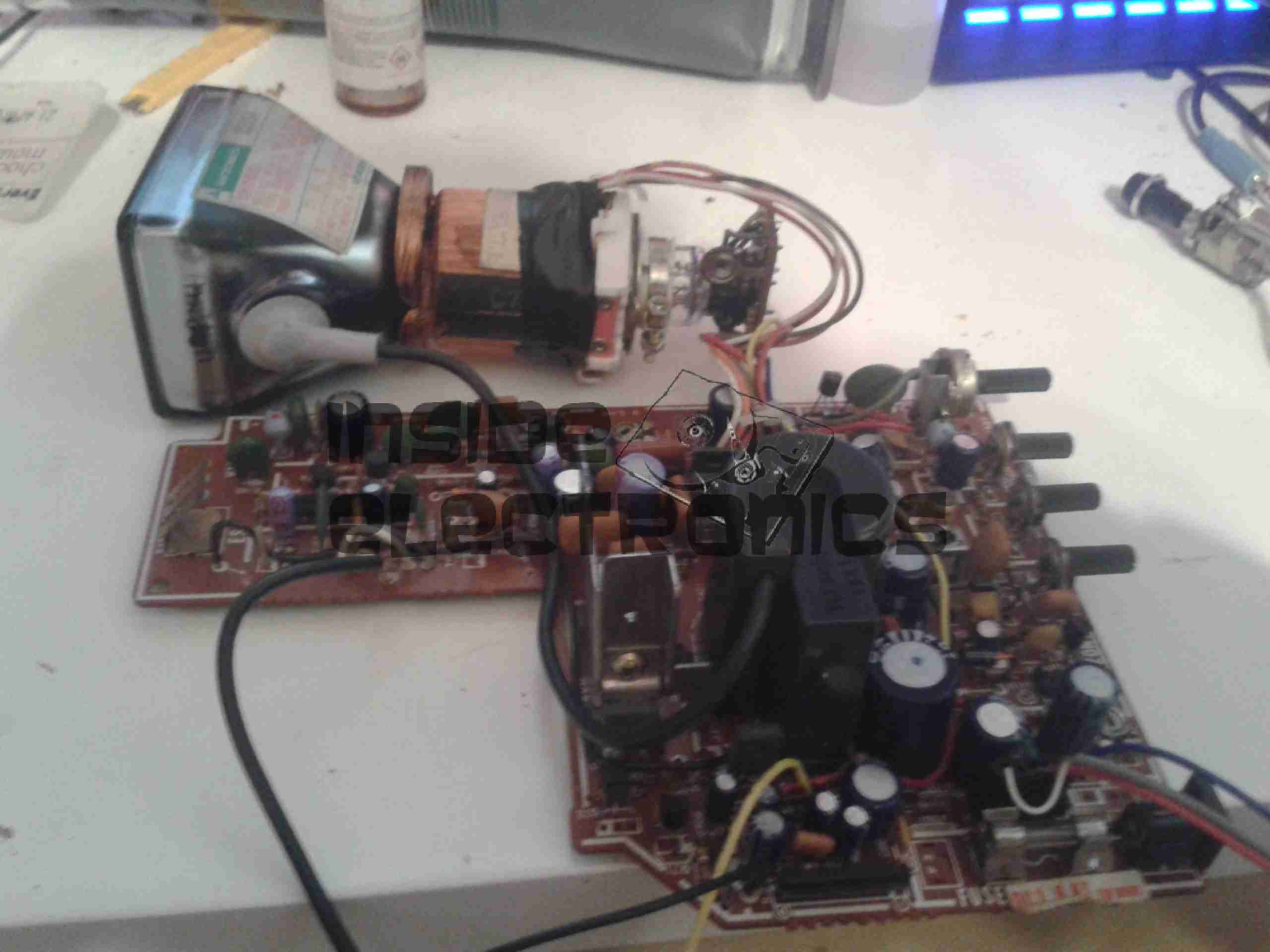
Here’s the TV in it’s native state. Running from 9v DC, or 6 D size cells. I’m guessing from somewhere around the 1970’s. Here is the CRT & associated drive circuitry, removed from the casing:
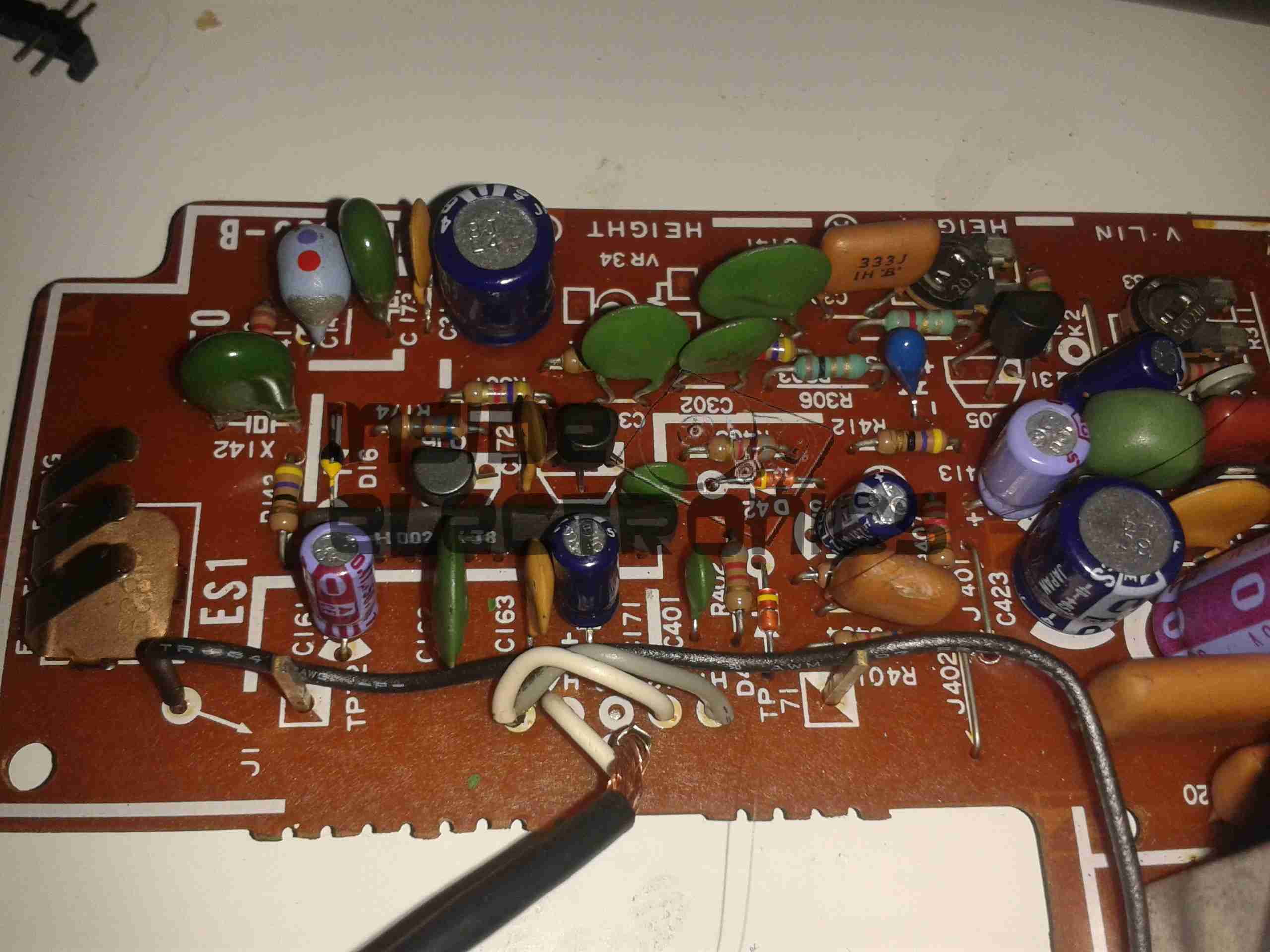
CRT Module
After dissecting the loom wiring between the CRT board & the RF/tuner board, I figured out I had to short out Pins 1,2 & 5 on the H header to get the CRT to operate straight from the power switch. This board also generates the required voltages & signals to drive the RF tuner section. I have removed the loom from this, as the PCB operates fine without. It doesn’t seem to be fussy about power input either: it’s specified at 9v, but seems to operate fine between 7.5v & 14.5v DC without issue.
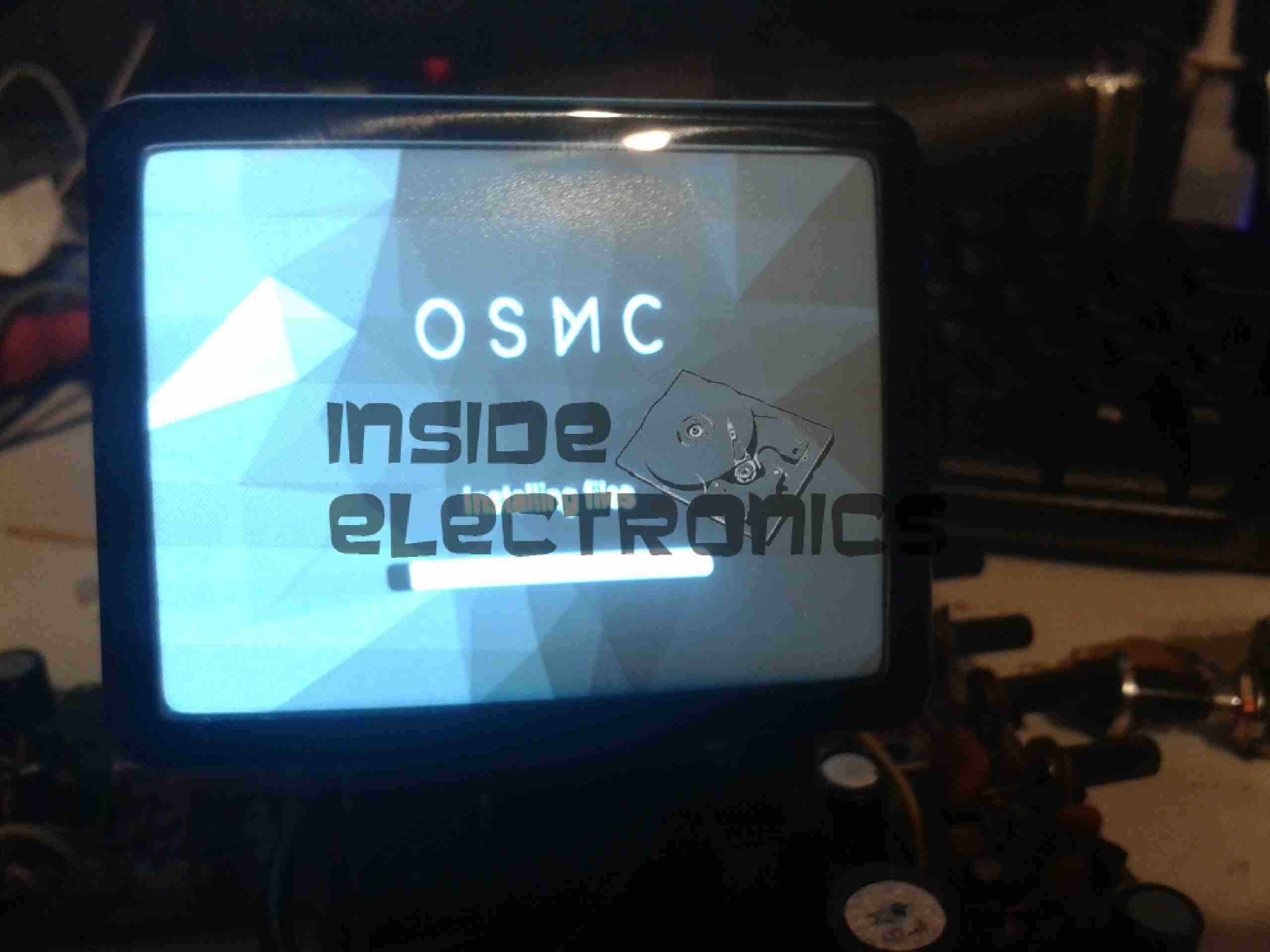
Video Connections
Tracing the wiring from the tuner PCB revealed a length of coax snaking off to the section marked Video/Sync. I successfully found the composite input!
Running OSMC
A quick bit of wiring to a Raspberry Pi, & we have stable video! For such an old unit, the picture quality is brilliant, very sharp focus.
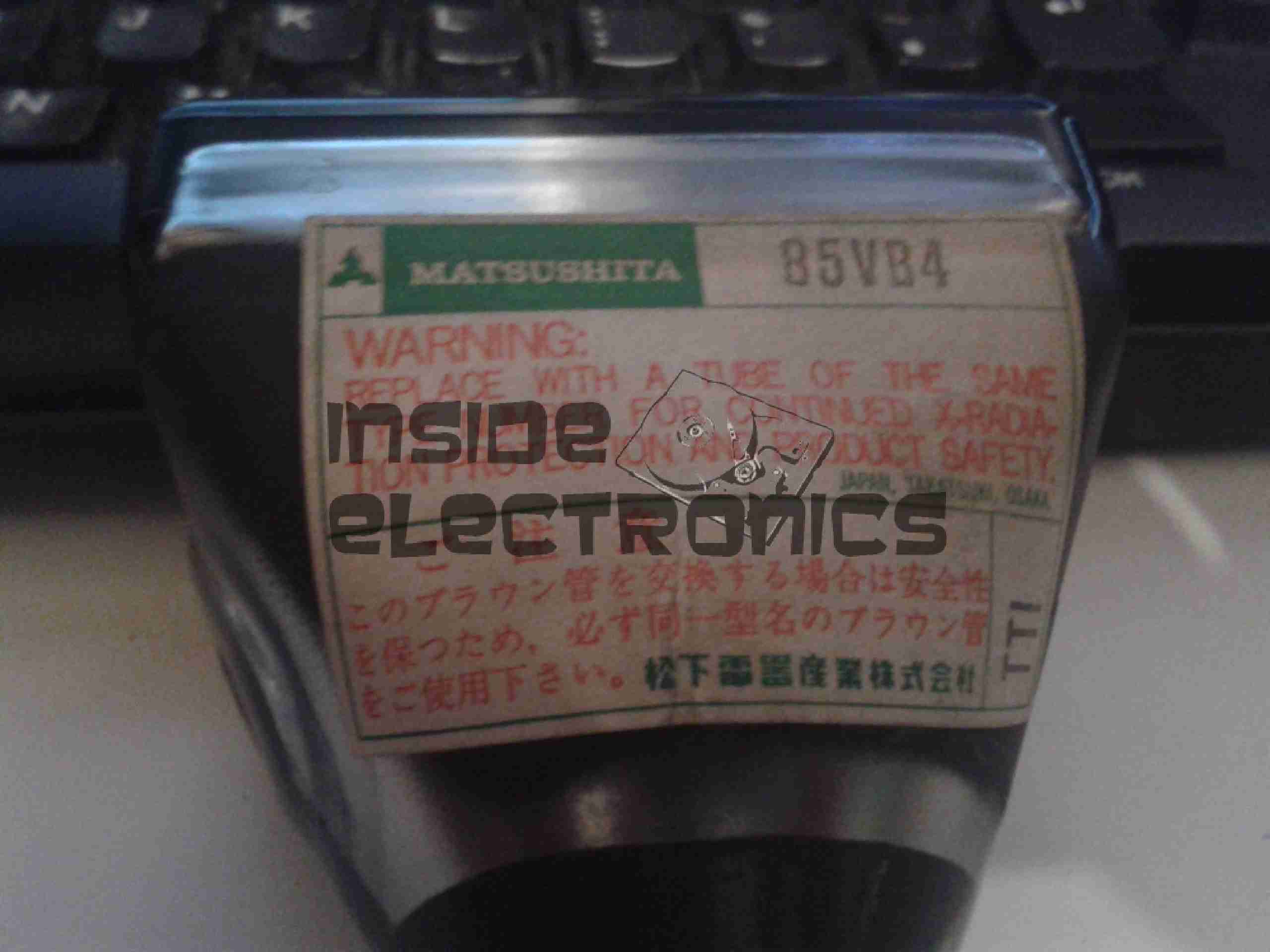
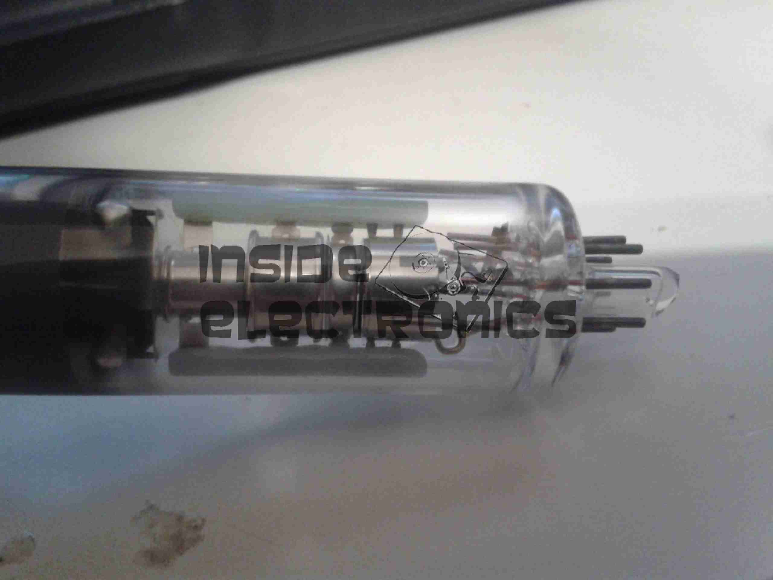
Matsushita 85VB4 CRT
Closeup of the CRT itself. I haven’t been able to find much data on this unit, but I’m guessing it’s similar to many commercial viewfinder CRTs.
Electron Gun Closeup
Amazingly, there isn’t a single IC in the video circuitry, it’s all discrete components. This probably accounts for the large overall size of the control PCB. Viewfinder CRTs from a few years later on are usually driven with a single IC & a few passives that provide all the same functions.
Here is the setup used to create the previous videos, the PiCE from Elson Designs makes the Pi water resistant, the only slight modification being to install a 2.5mm DC Barrel Jack into one of the grommet holes in the rear coupled with a custom DC-DC converter to power the setup.
A break from normal programming now to show a weekend canal cruise on the Macclesfield canal. Going from Marple to Poynton & returning later in the afternoon. This video was shot with the Raspberry Pi waterproofed with the PiCE From Elson Designs.
Here is a compiled version of the Linux kernel for the Raspberry Pi useful for those who have USB/Serial touchscreens of the 3M Microtouch or eloTouch variety.
Works with a freshly installed & fully updated Raspbian image.
I have tested this only with a 3M Microtouch EXII controller currently.
Simply overwrite the /lib folder with the new modules & overwrite the main kernel image in /boot to install.
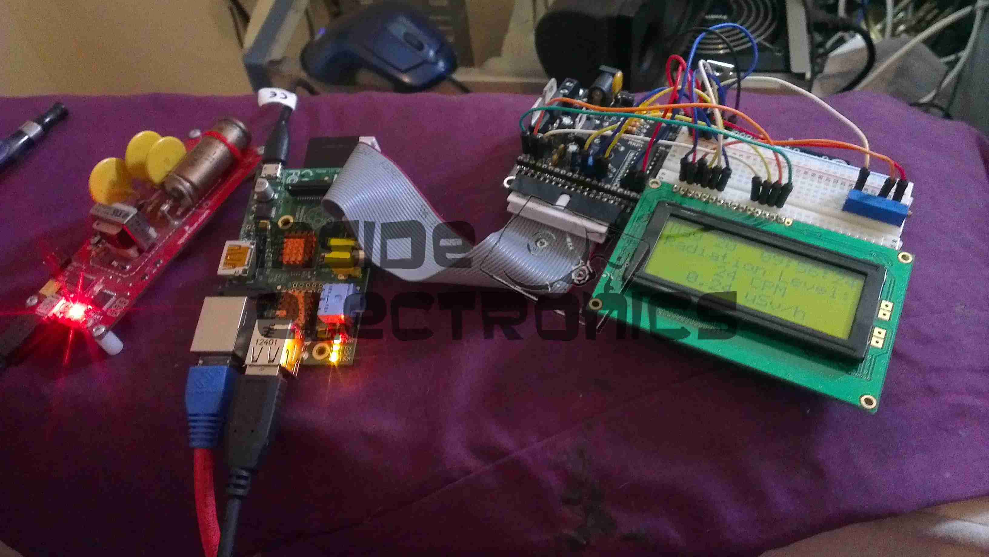
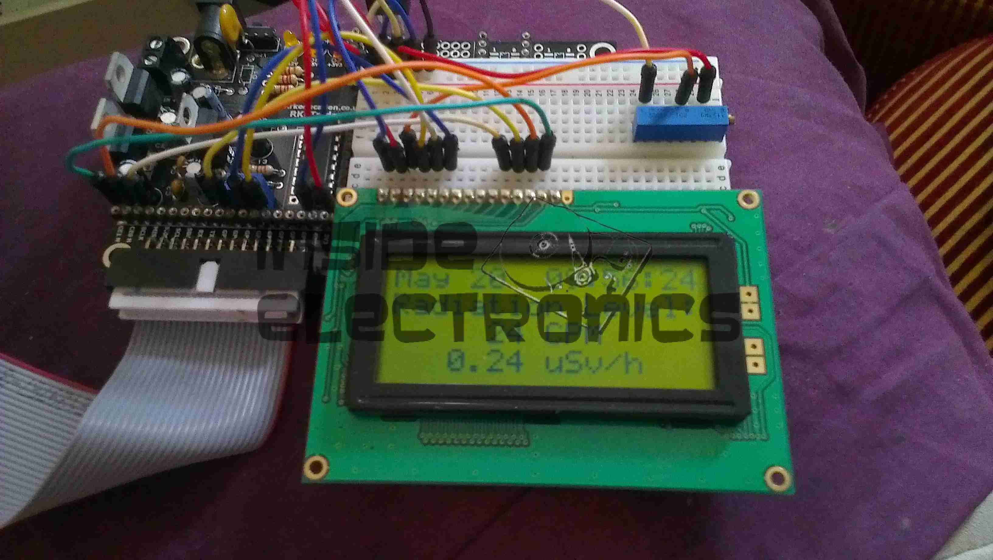
Here’s my latest project with the Pi: interfacing it with the Sparkfun Geiger counter & outputting the resulting data to a character LCD.
The geiger counter is interfaced with it’s USB port, with the random number generator firmware. A Python script reads from the serial port & every minute outputs CPM & µSv/h data to the display.
The Python code is a mash of a few different projects I found online, for different geiger counters & some of my own customisations & code to write the info to the display & convert CPM into µSv/h.
This also writes all the data into a file at /var/log/radlog.txt
As the first USB hub I was using was certainly not stable – it would not enumerate between boots & to get it working again would require waiting around 12 hours before applying power, it has been replaced. This is a cheapie eBay USB hub, of the type shown below.
These hubs are fantastic for hobbyists, as the connections for power & data are broken out on the internal PCB into a very convenient row of pads, perfect for integration into many projects.
Breakout Hub
I now have two internal spare USB ports, for the inbuilt keyboard/mouse receiver & the GPS receiver I plan to integrate into the build.
These hubs are also made in 7-port versions, however I am not sure if these have the same kind of breakout board internally. As they have the same cable layout, I would assume so.
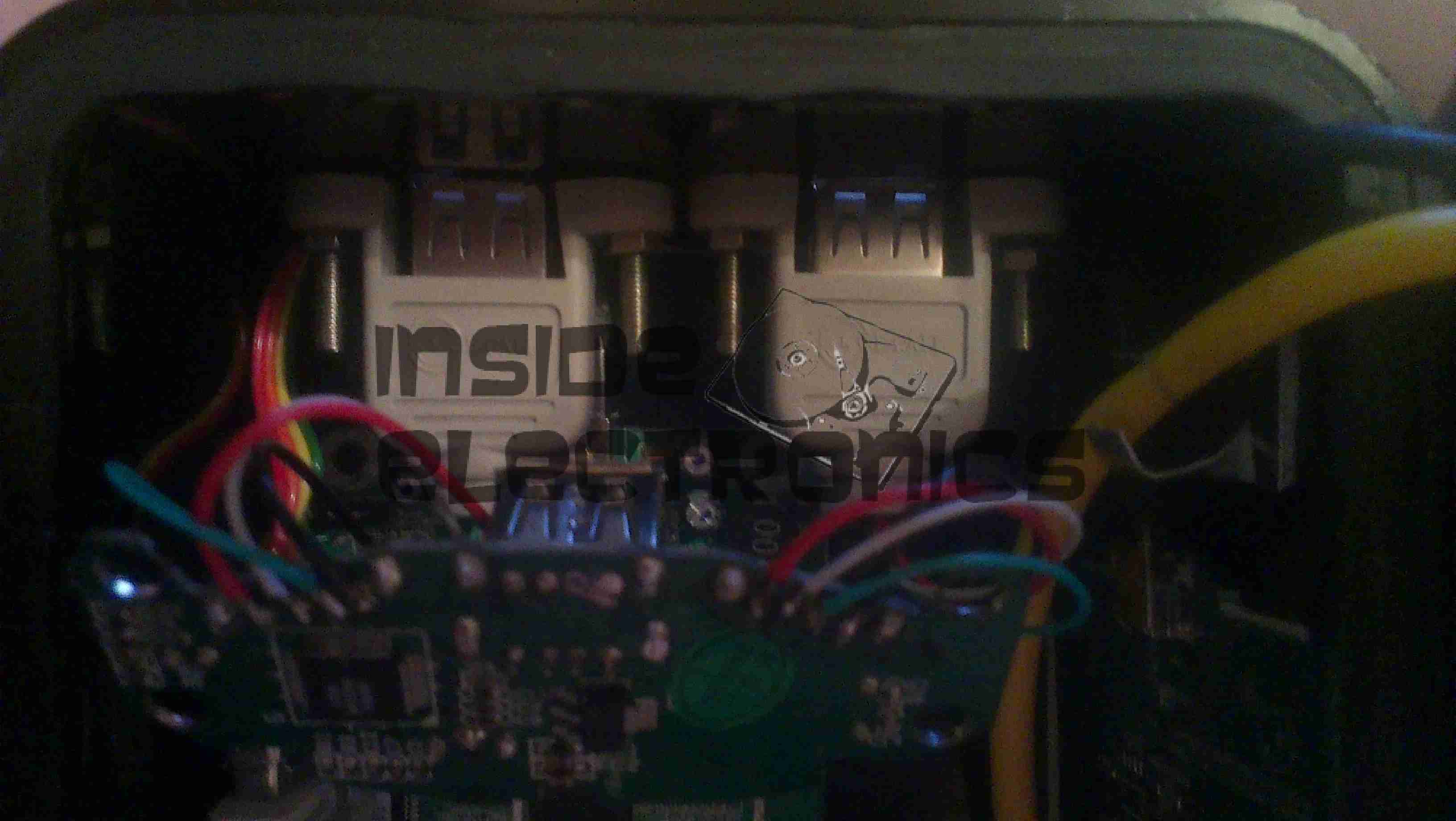
Connector Panel
Here is a closeup of the back of the connectors, showing a couple of additions.
I have added a pair of 470µF capacitors across the power rails, to further smooth out the ripple in the switching power supply, as I was having noise issues on the display.
Also, there is a new reset button added between the main interface connectors, which will be wired into the pair of pads that the Raspberry Pi has to reset the CPU.
This can be used as a power switch in the event the Pi is powered down when not in use & also to reset the unit if it becomes unresponsive.
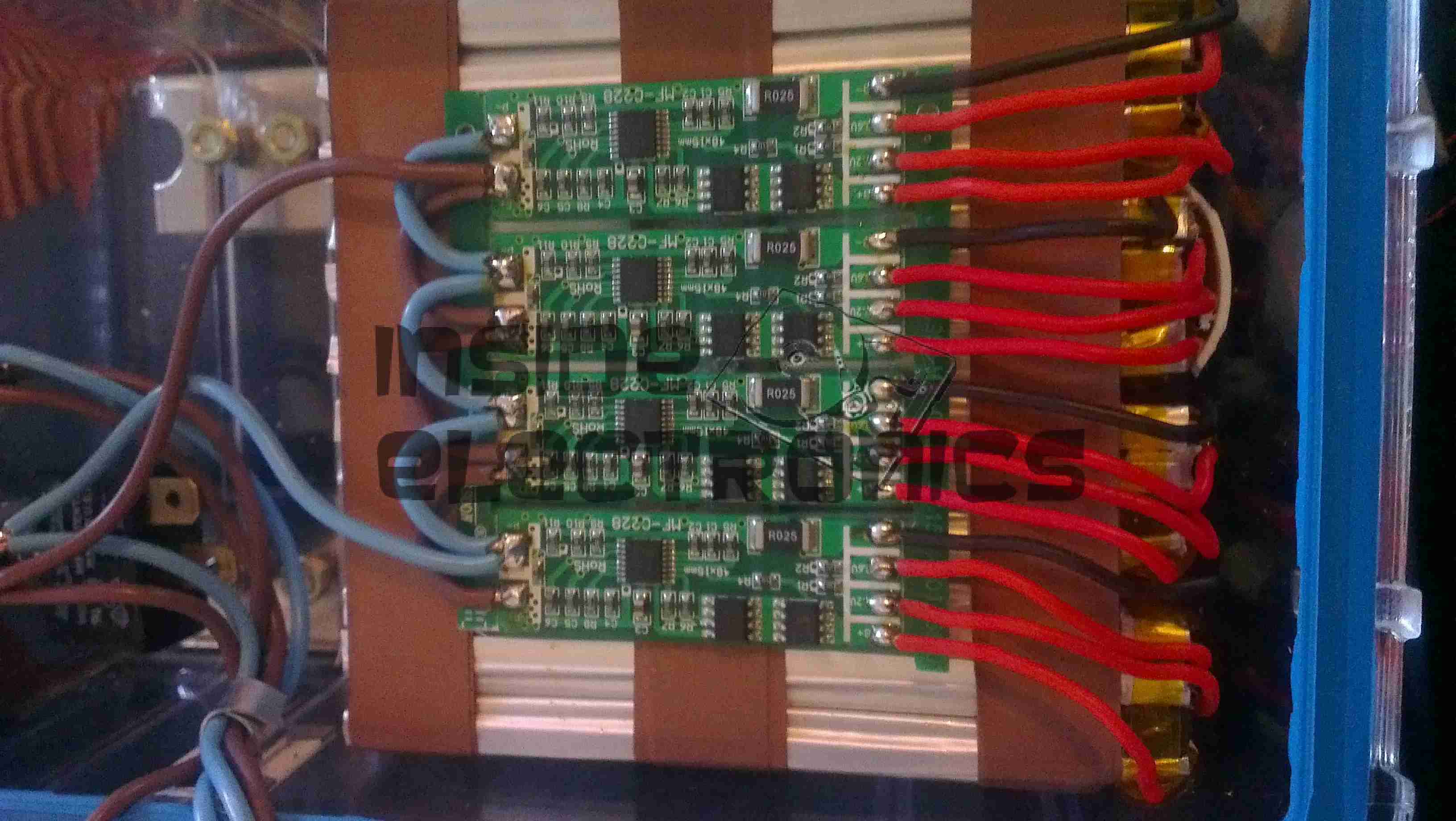
The final part for the battery pack has finally arrived, the PCM boards. These modules protect the cells by cutting off the power at overcharge, undercharge & overcurrent. Each cell is connected individually on the right, 12v power appears on the left connections. These modules also ensure that all the cells in the pack are balanced.
A few modifications were required to the SMPS modules to make the power rails stable enough to run the Pi & it’s monitor. Without these the rails were so noisy that instability was being caused.
I have replaced the 100µF output capacitors & replaced them with 35v 4700µF caps. This provides a much lower output ripple.
There are also heatsinks attached to the converter ICs to help spread the heat.
Progress is finally starting on the power supply unit for the Pi, fitted into the same case style as the Pi itself, this is an 8Ah Li-Poly battery pack with built in voltage regulation.
Regulator Boards
Here are the regulators, fixed to the top of the enclosure. These provide the 12v & 5v power rails for the Pi unit, at a max 3A per rail.
Battery Pack
In the main body of the case the battery pack is fitted. This is made up of 4 3-cell Li-Poly RC battery packs, rated at 2Ah each. All wired in parallel this will provide a total of 8Ah at 12.6v when fully charged.
Powered Up
Here the regulators are powered up from a 13v supply for testing. I have discovered at full load these modules have very bad ripple, so I will be adding extra smoothing capacitors to the power rails to compensate for this.
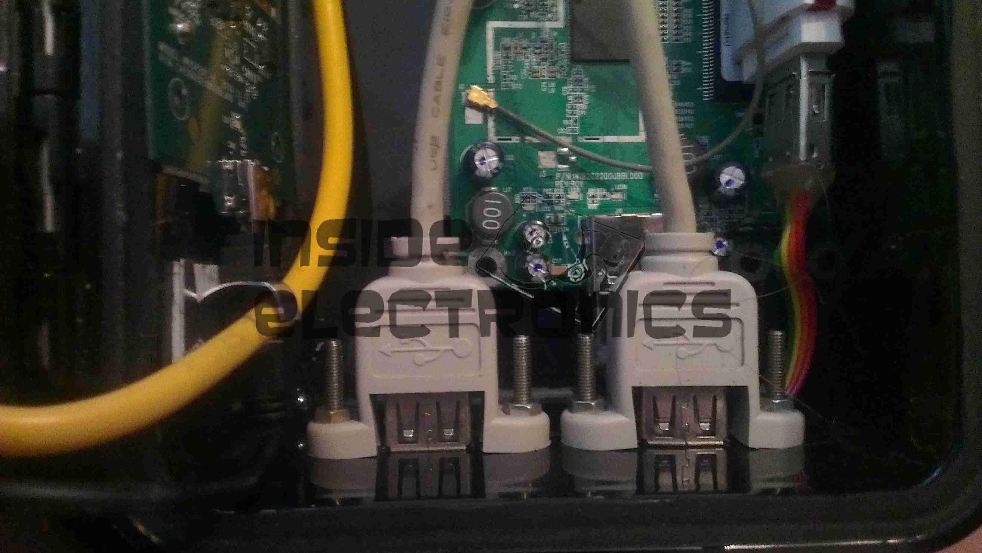
I/O
Here are the connectors on the top of the unit, outputting the two power rails to the Pi & the DC barrel jack that will be used to charge the pack.
The hub for the external USB ports has been fitted here, with the two ports hardwired to the pads where once there were USB A sockets. This hub will also accommodate the wireless receiver for the mini keyboard & mouse, in the remaining port that will sit between the external USB ports.
USB Ports
In this gap between the ports is where the wireless receiver will sit for the keyboard & mouse, the pair of screws securing the external ports in the centre have been shortened to make more room.
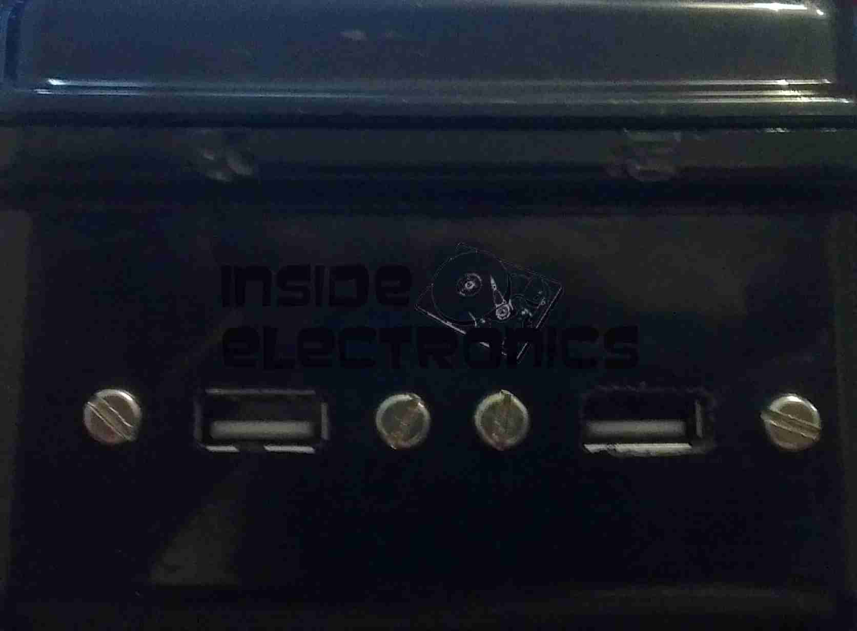
For convenience, a pair of USB ports have been fitted to the wearable Pi, which open on the bottom of the unit. These will be hardwired into a 4-port USB hub which will also support the wireless adaptor for the mini-keyboard that is to be used with the device.
USBs
The two USB ports on the bottom of the casing.
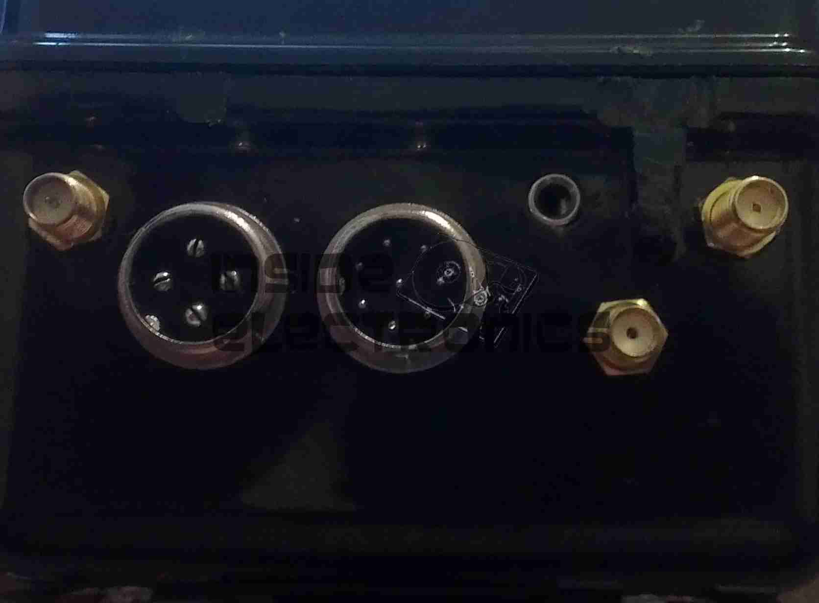
External Connections
The external connectors are also complete. The audio jack & second WiFi antenna port are fitted.
The audio is normally routed to the LCD display speaker, until a jack is plugged into the 3.5mm socket.
Here is the project I’m currently working on. A completely wearable computing platform based on the Raspberry Pi & the WiFi Pineapple.
Above can be seen the general overview of the current unit.
On the left:
Alfa AWUS036NHA USB High Power WiFi Network Interface
512MB Model B Raspberry Pi, 16GB SD card, running Raspbian & LXDE Desktop. Overclocked to 1GHz.
On the right:
WiFi Pineapple router board
USB 3G card.
The WiFi, Pineapple & 3G all have external antenna connections for a better signal & the whole unit locks onto the belt with a pair of clips.
The Raspberry Pi is using the composite video output to the 7″ LCD I am using, running at a resolution of 640×480. This gives a decent amount of desktop space while retaining readability of the display.
The case itself is a Pelican 1050 hard case, with it’s rubber lining removed. The belt clips are also a custom addition.
Connections
Here are the connections to the main unit, on the left is the main power connector, supplying +5v & +12v DC. The plug on the right is an 8-pin connection that carries two channels of video, mono audio & +12v power to the display.
Currently the only antenna fitted is the 3G.
Connectors
Closeup of the connections for power, audio & video. The toggle switch is redundant & will soon be replaced with a 3.5mm stereo jack for headphones, as an alternative to the mono audio built into the display.
Test Run
Current state of test. Here the unit is running, provided with an internet connection through the Pineapple’s 3G radio, funneled into the Pi via it’s ethernet connection.
Pi Goodness!
Running on a car reversing camera monitor at 640×480 resolution. This works fairly well for the size of the monitor & the text is still large enough to be readable.
Stay tuned for Part 2 where I will build the power supply unit.
Here are the first set of mods & improvements to the RasPi Experiment board. Instead of the solder-point experiment space, I have added a standard mini-breadboard, even though it’s a little too long to fit on the board properly.
In the DIP breakout, is a MAX232 TTL-RS232 interface IC, useful for interfacing directly to the Pi’s UART, made available on the GPIO breakout. I will be hardwiring the MAX232 IC into the GPIO port, & fitting headers to the relevant pins on the IC breakout to make interfacing to the Pi easier.
All the MAX232 requires to operate are a 5v supply & 4 1µF capacitors.
The new TO220 device next to the breadboard is a TIP121 darlington power transistor.This is rated at 80v 5A continuous. Useful for driving large loads from a GPIO output.
After seeing these on eBay for £8.99 I thought it might be a good deal – interfacing with the RasPi’s GPIO & it has built in power supplies.
As a kit, it was very easy to assemble, the PCB quality is high, and is a fairly good design. It worked first time, the regulators hold the rails at the right voltages.
However there are some issues with this board that bug me.
The documentation for the kit is *AWFUL*. No mention of the regulators on the parts list & which goes where – I had to carefully examine the schematics to find out those details.
The 4x 1N1007 diodes required weren’t even included in the kit! Luckily I had some 1N4148 high speed diodes lying around & even though they’re rated for 200mA continuous rather than the specified part’s 1A rating, the lack of heatsinking on the regulators wouldn’t allow use anywhere near 1A, so this isn’t much of a problem.
Component numbering on the silkscreen isn’t consistent – it jumps from R3 straight to R6! These issues could be slightly confusing for the novice builder, and considering the demographic of the RasPi, could be seen as big issues.
On the far left of the board are the 5v & 3.3v regulators, well placed on the edge of the board in case a heatsink may be required in the future. However the LM317 adjustable regulator is stuck right in the middle of the PCB – no chance of being able to fit a heatsink, & the device itself seems incredibly cheap – the heatsink tab on the back of the TO-220 is the thinnest I have ever seen. Not the usual 2-3mm thick copper of the 5v & 3.3v parts – but barely more than a mm thick, so it’s not going to be able to cope with much power dissipation without overheating quickly.
As the adjustable rail can go between ~2.5v – 10v, at the low end of the range the power dissipation is going to shoot through the roof.
The GPIO connector – this could have been done the other way, at the moment the ribbon cable has to be twisted to get both the Pi & the GPIO board the same way up. Just a slight fail there. See the image below
Plugged In
The power rails are not isolated out of the box – there is no connection between the 5v & 3.3v rails & the Pi’s GPIO, but the GND connections are linked together on the board.
Getting the ribbon cable through the hole in the ModMyPi case was a bit of a faff – the connector is too big! I had to squeeze the connector through at a 45° angle. The case is also remarkably tight around the connector once it’s fitted to the board – clearly the designers of the case didn’t test the an IDC connector in the case before making them!
Everything does fit though, after a little modification.
All Cased Up
Here is the unit all built up with the case. The top cover just about fits with the IDC connector on the GPIO header.
More to come once I get some time to do some interfacing!
This is a little script to make OMXPlayer on the Raspberry Pi cycle through every file in a specified folder, useful for playing sequential movies or series of episodes.
#!/bin/bash
if [ x"$1" = x"help" -o x"$1" = x"--help" -o x"$1" = x"-help" ];then
echo "Usage: omxseries [folder path]"
echo "Audio Mode can be either 'hdmi' or 'local'."
echo "Folder Path is the full path to the video files on your system."
echo "This script will attempt to play every file in the target folder, with any file extension,"
echo "so ensure that only valid video files are present in the target folder to avoid errors."
exit
fi
for file in $2/*
do
 omxplayer -o $1 $file
done
Example:
[root@raspbian ~]# omxseries hdmi /media/stuff/videos
would play everything in /media/stuff/videos and send the audio over the HDMI port.
Finally, some protection for my Raspberry Pi! The PCB fit is slightly loose, but that was quickly sorted with the application of a couple of spots of hot glue in the corners.
Unfortunately, the case is a couple of mm too small to fit the main board from the Pico Projector inside, so I won’t be butchering that into the case with the Pi as yet. What is required is an interface to the display engine from the Pi’s DSI interface.
Pi Cased Up
The pi all boxed. up. The only thing that this case would now require is a lightpipe to direct the LED’s light to the openings in the case, as they are very difficult to see at present.
Tip Jar
If you’ve found my content useful, please consider leaving a donation by clicking the Tip Jar below!
All collected funds go towards new content & the costs of keeping the server online.