Posted on Leave a comment

JVC CV-F503PAL Viewfinder

EVF Bottom
EVF Bottom

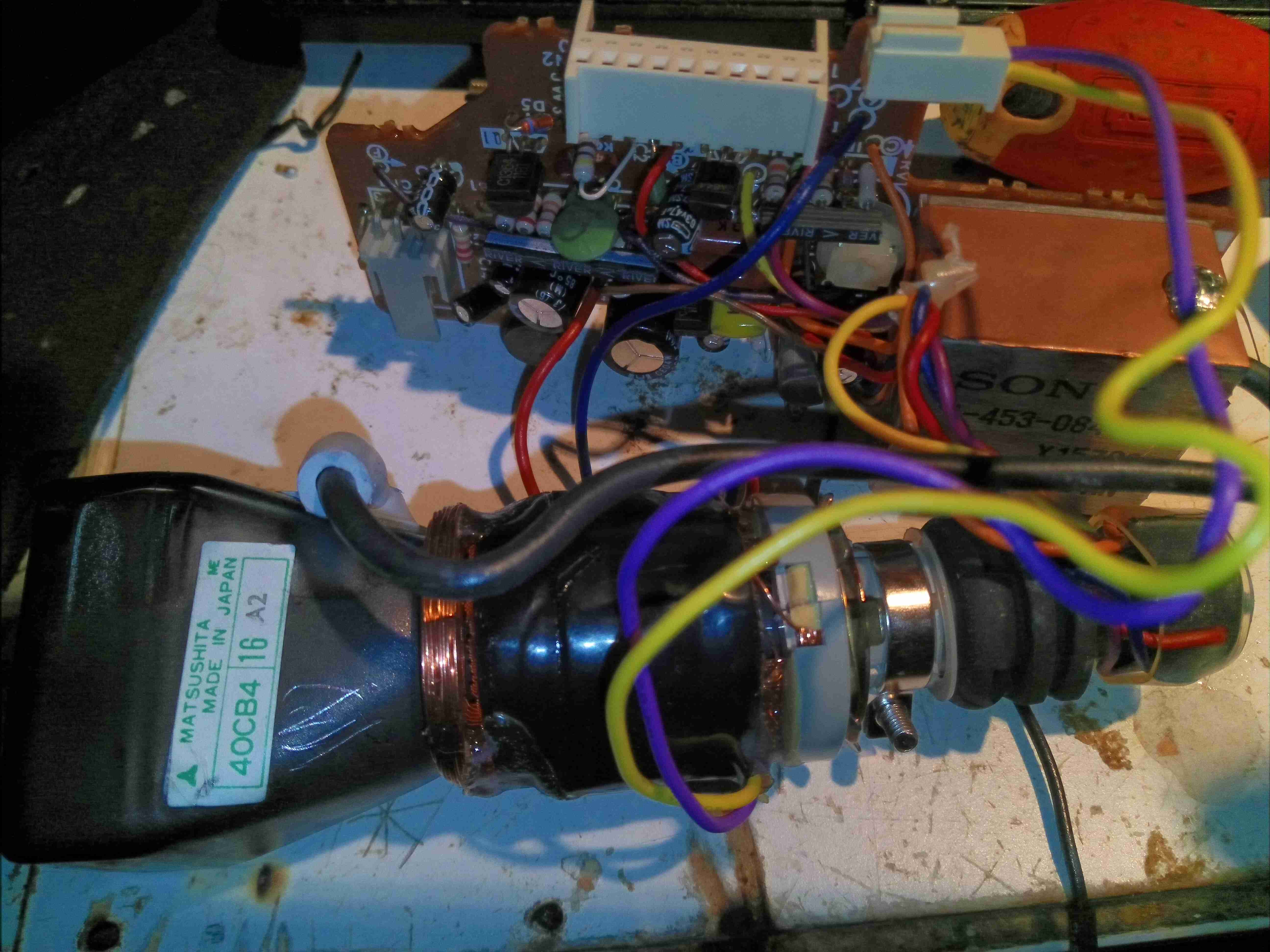
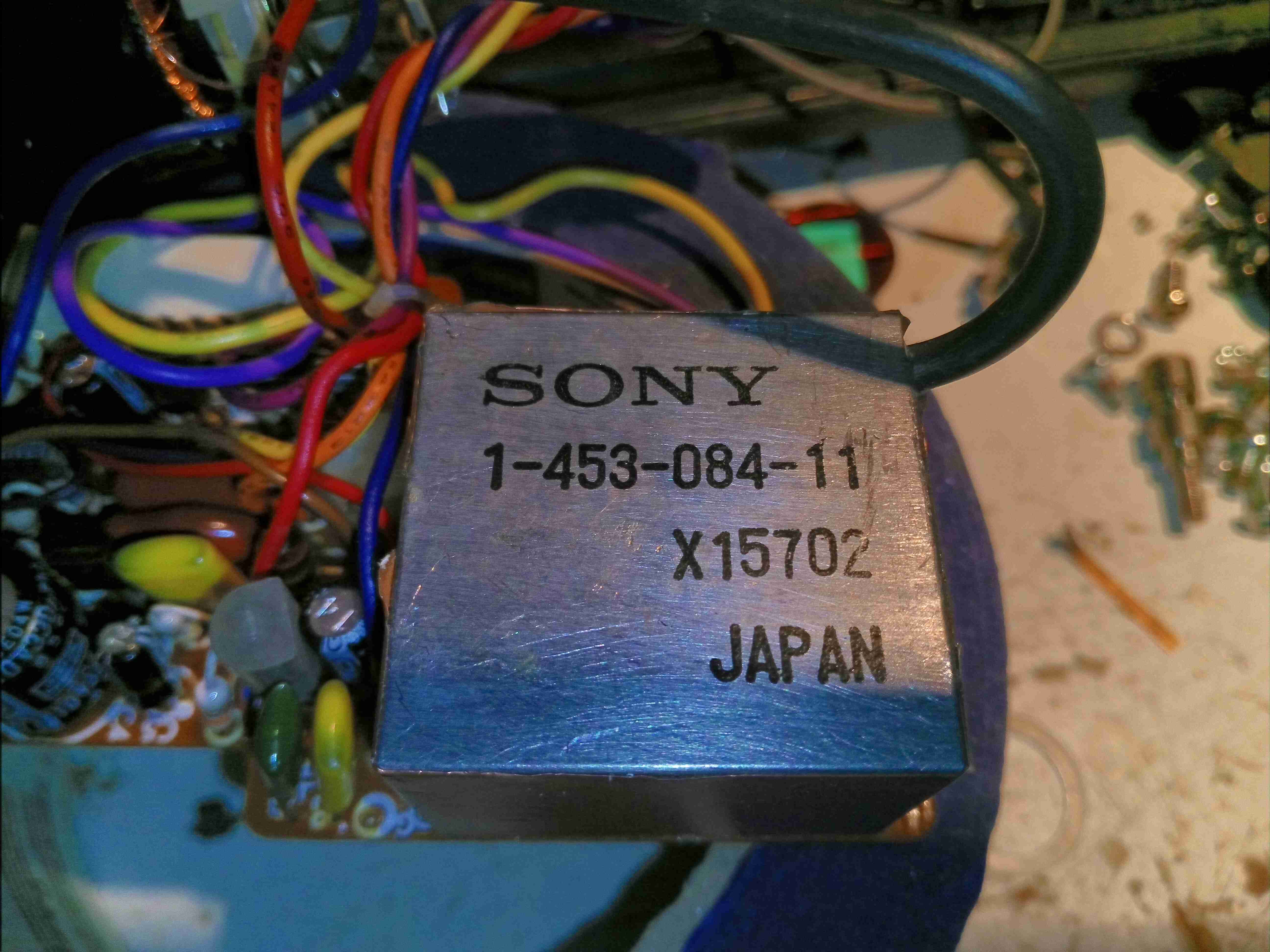
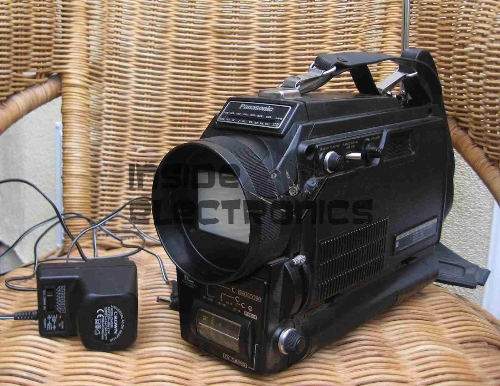
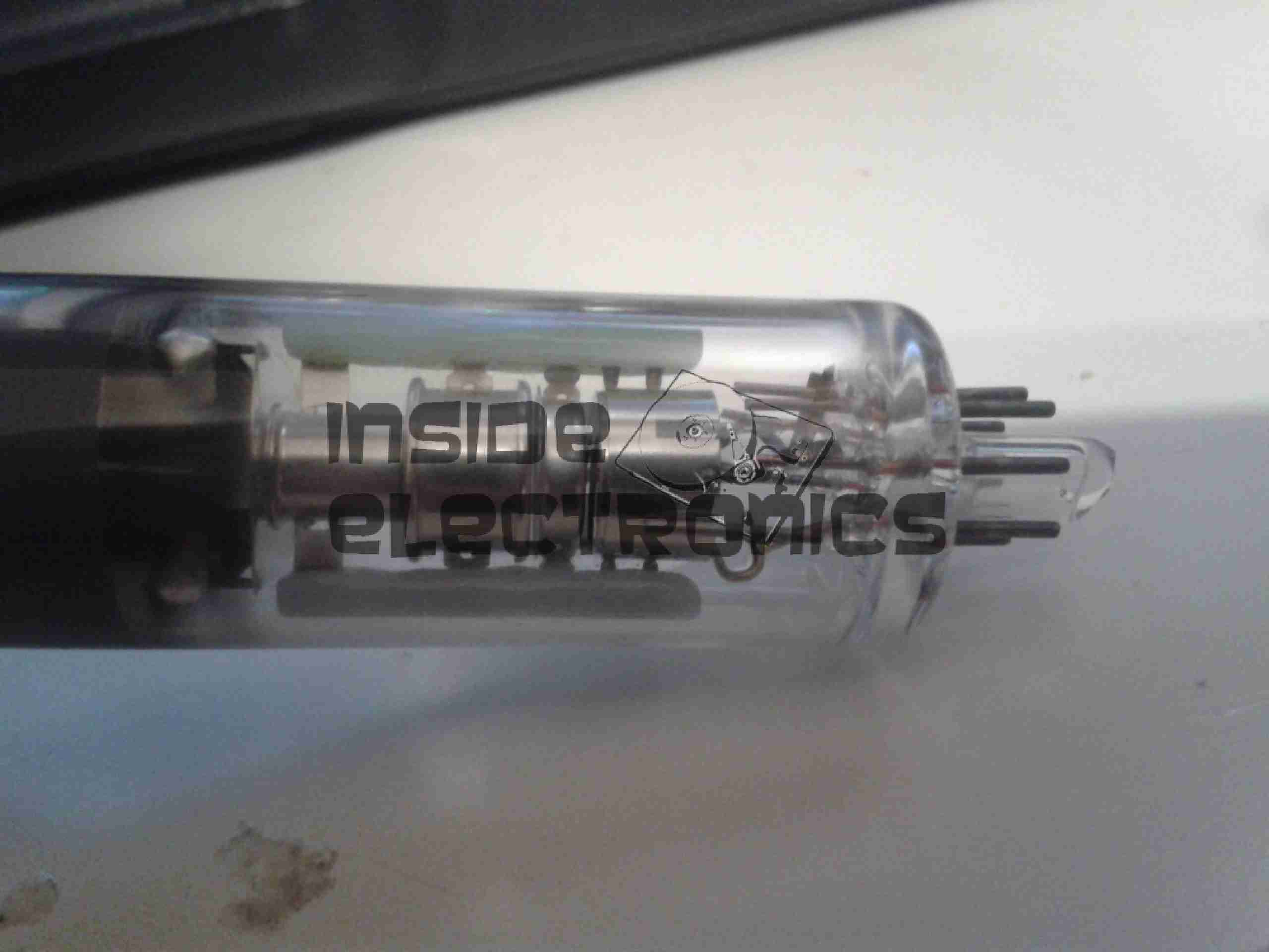
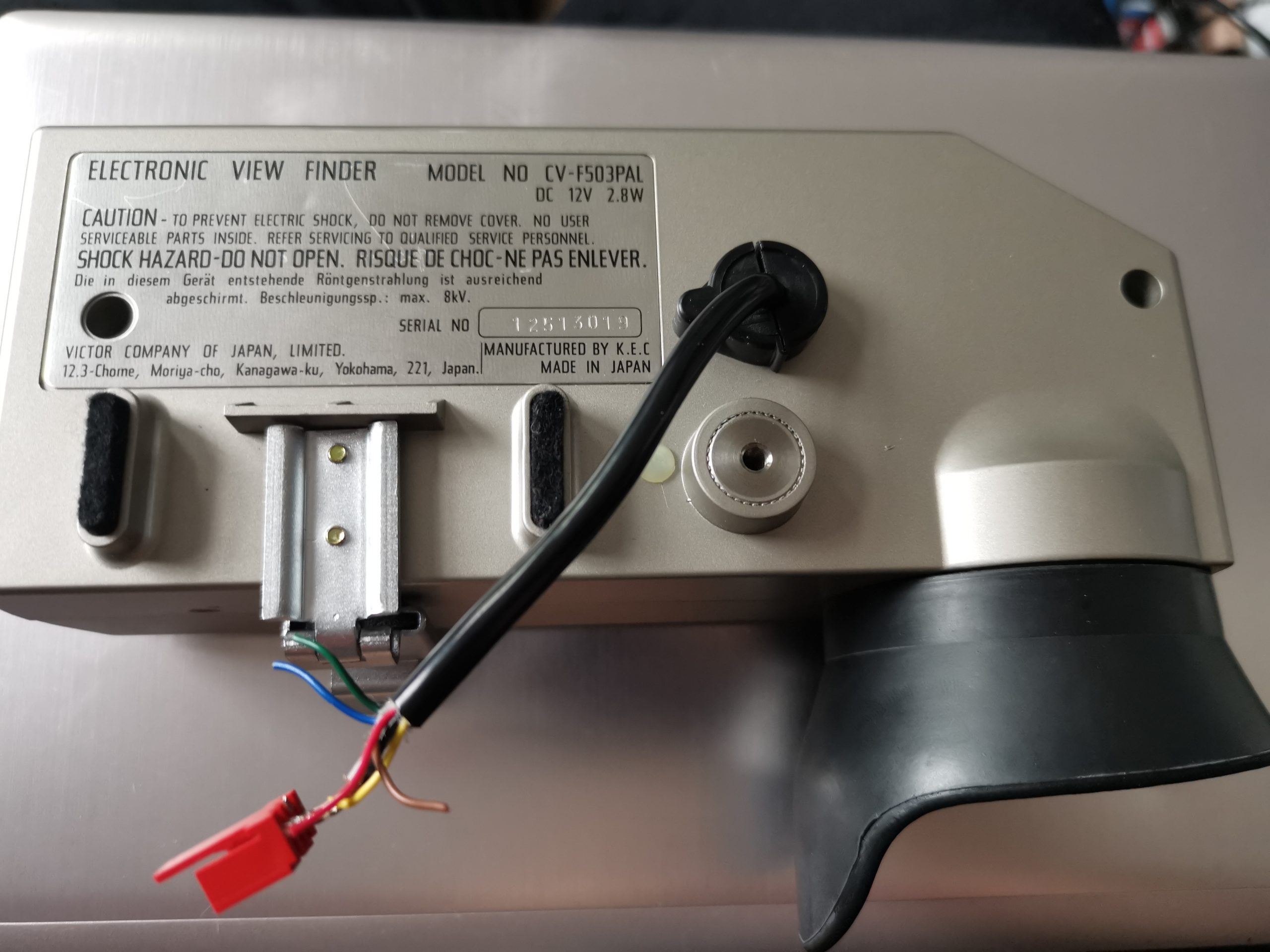
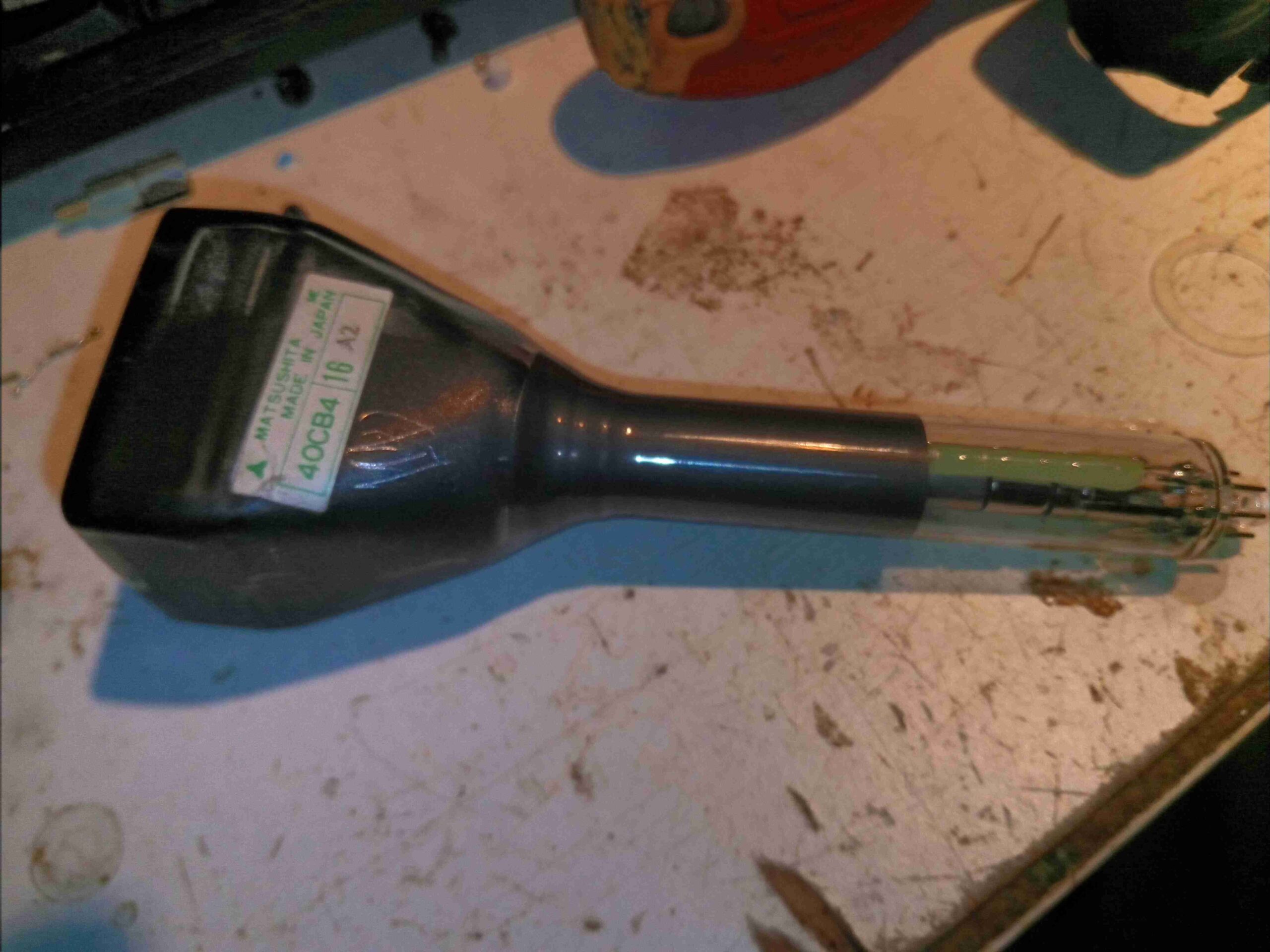
It’s time for another CRT-based post! This time it’s a Matsushita 40CB4-based viewfinder from 1980. These came from JVC colour tube cameras, and are physically massive! I’ve already worked out the pinout on the multicore cable here & attached a usable connector.

Information Label
Information Label

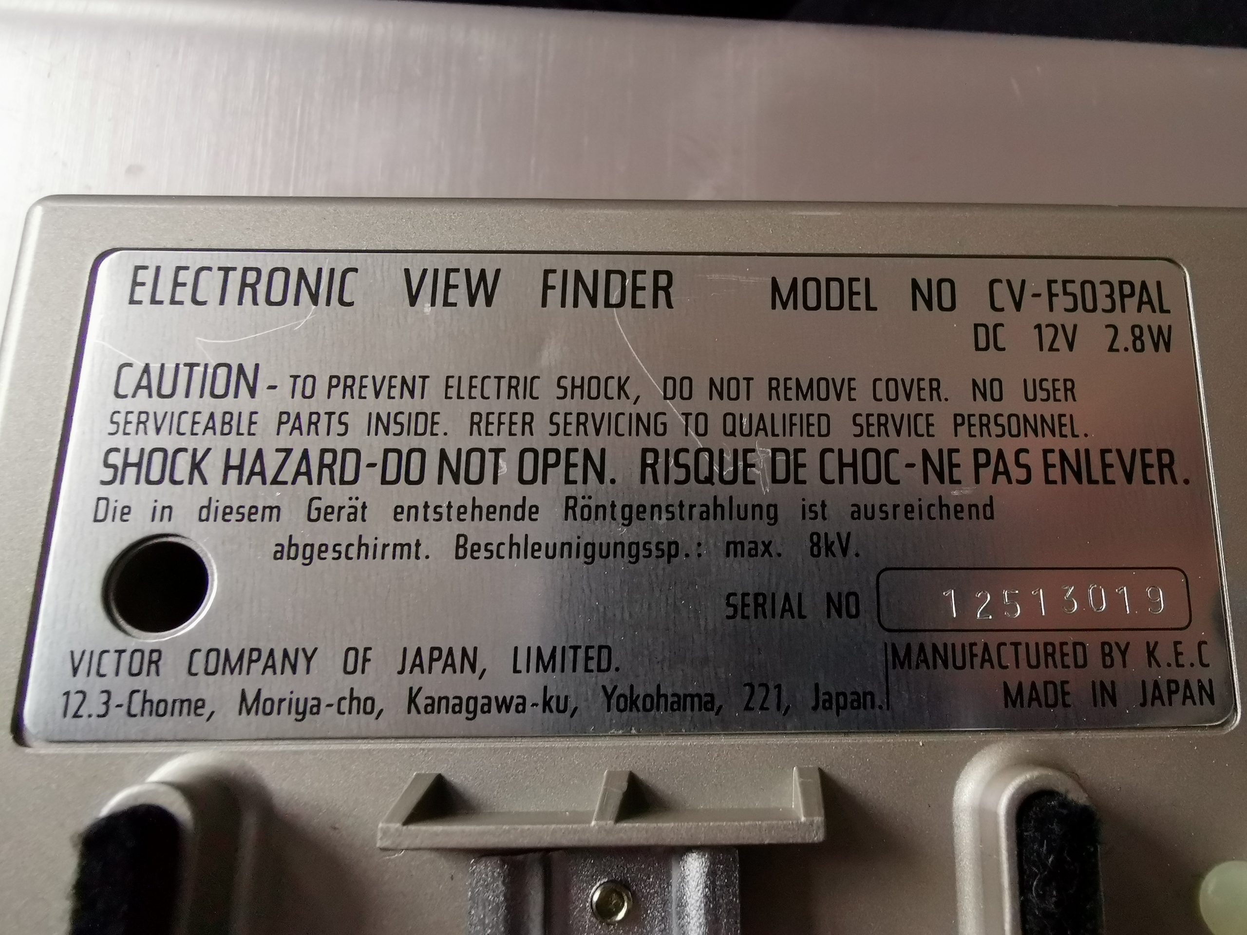
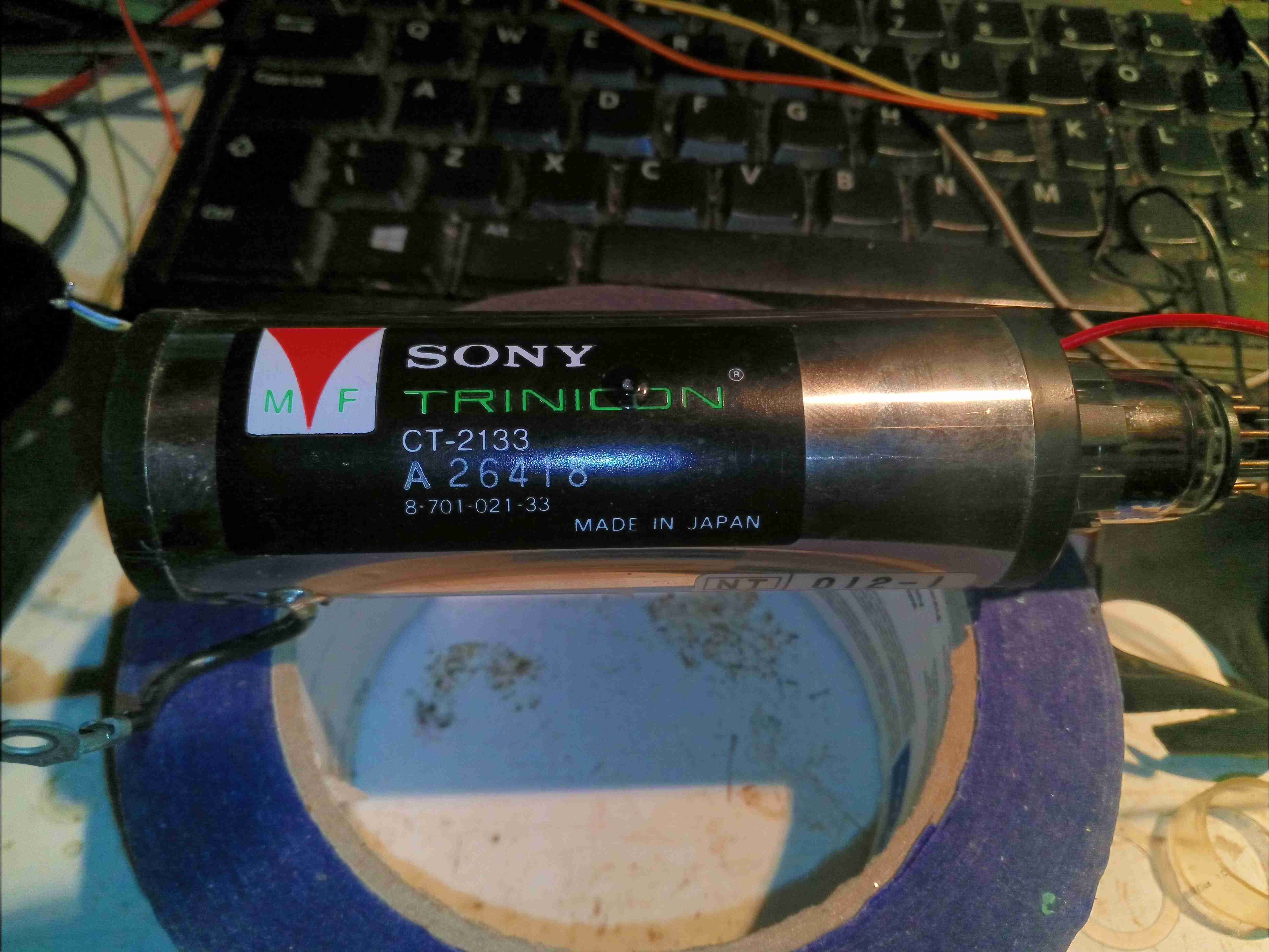
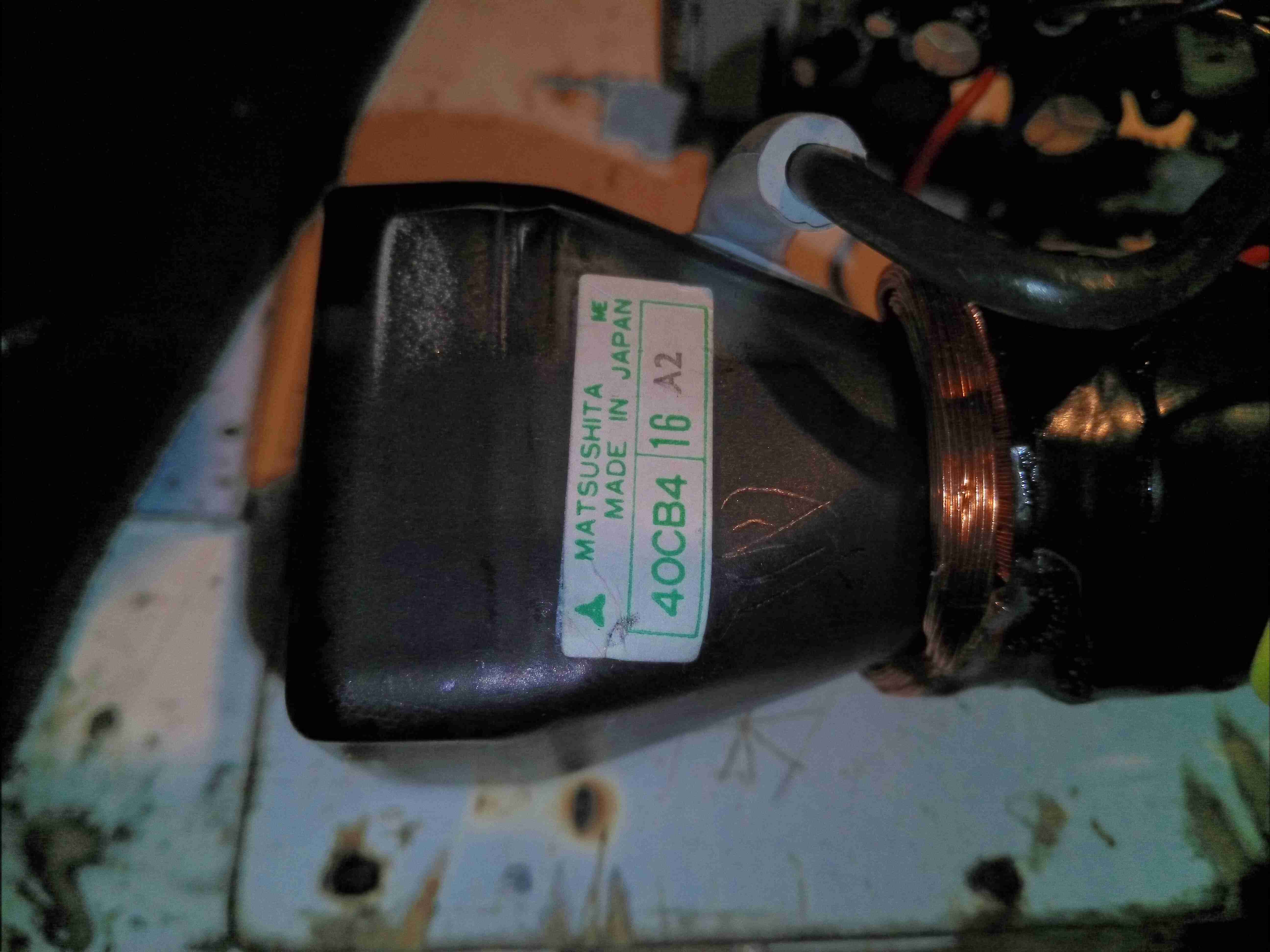
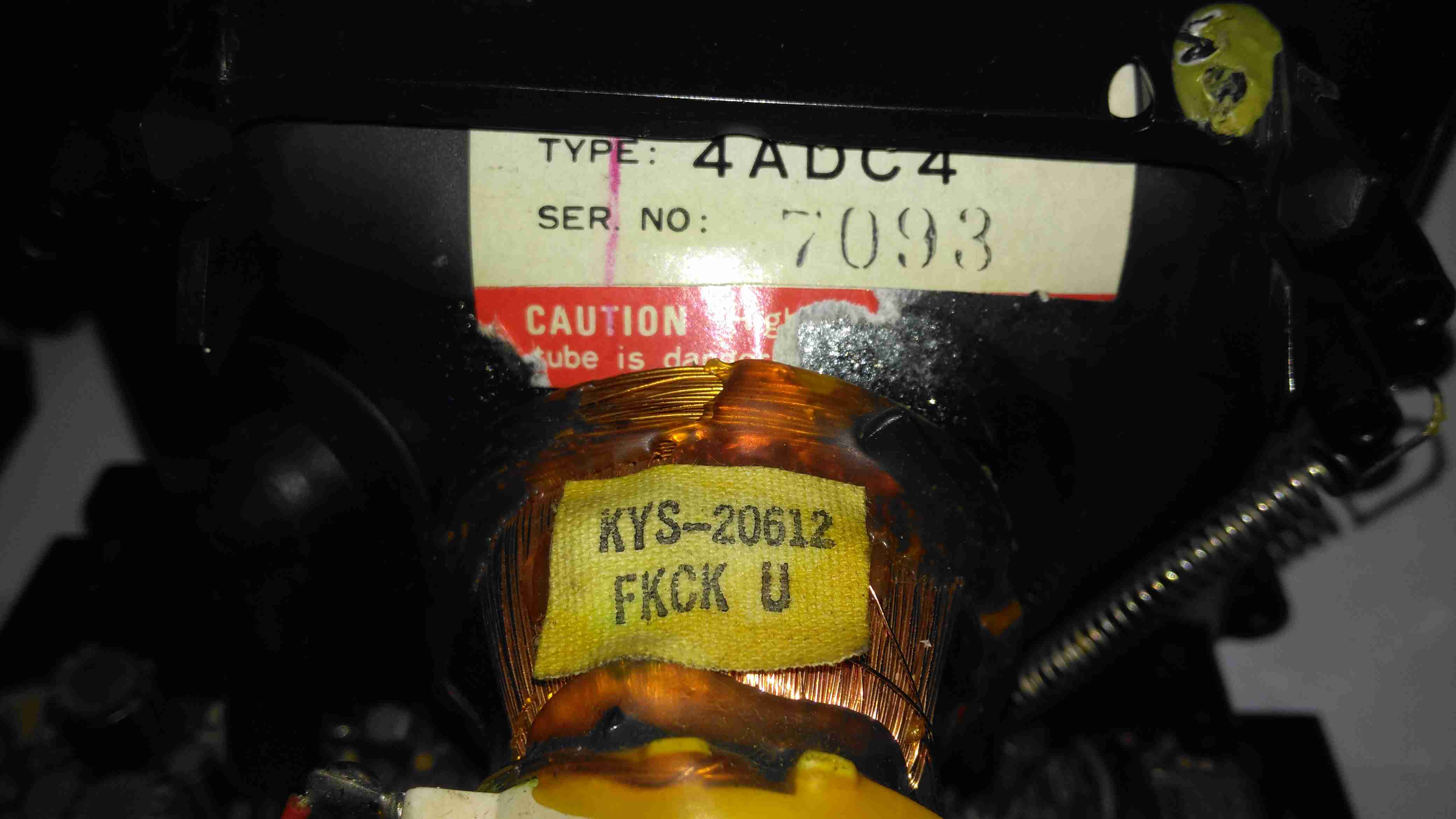
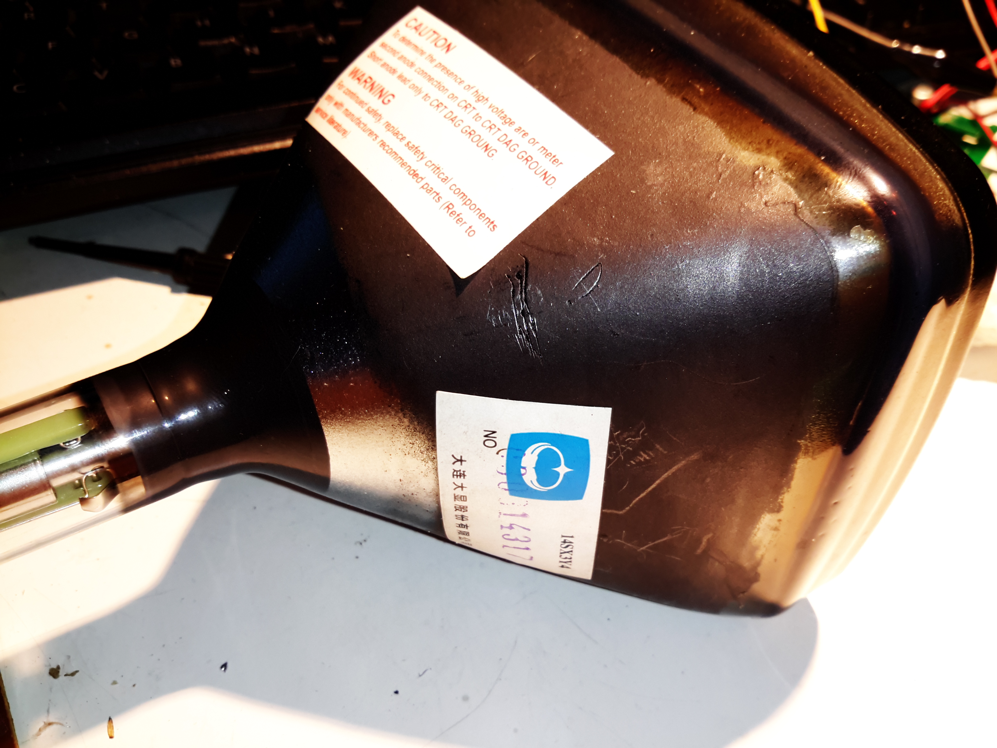
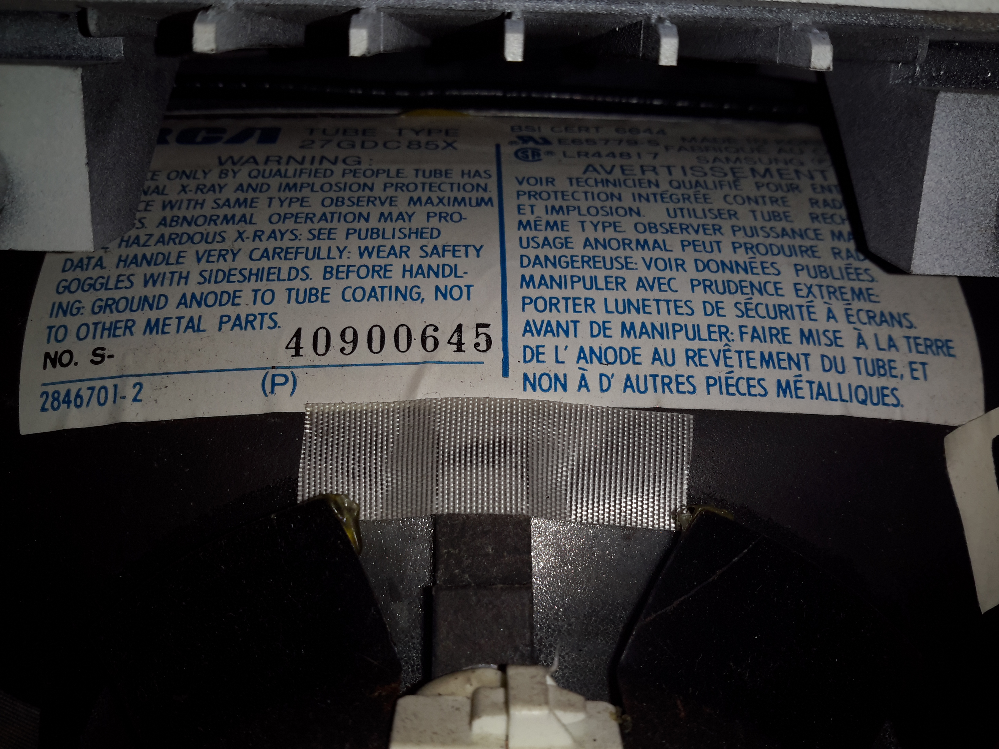
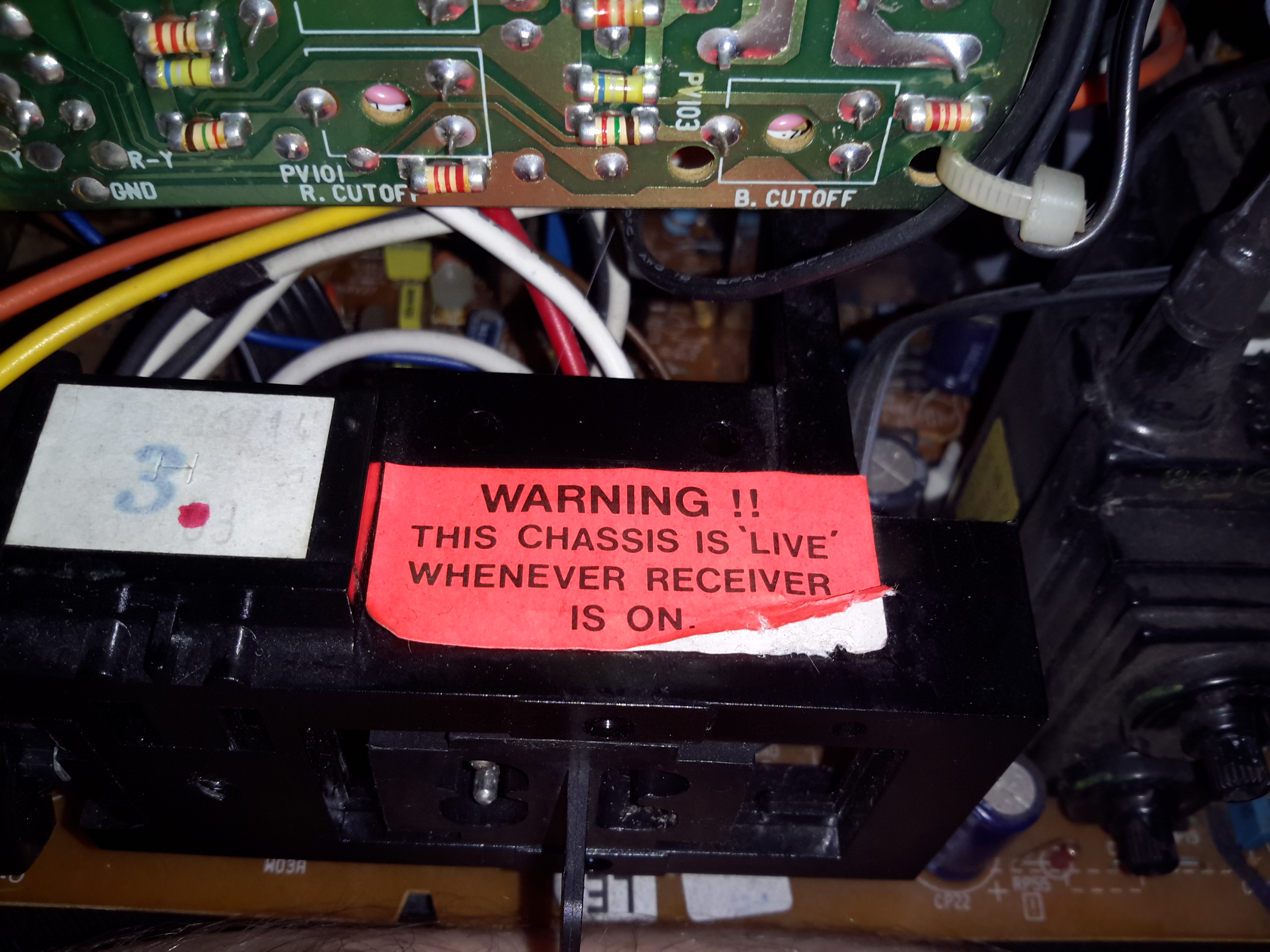
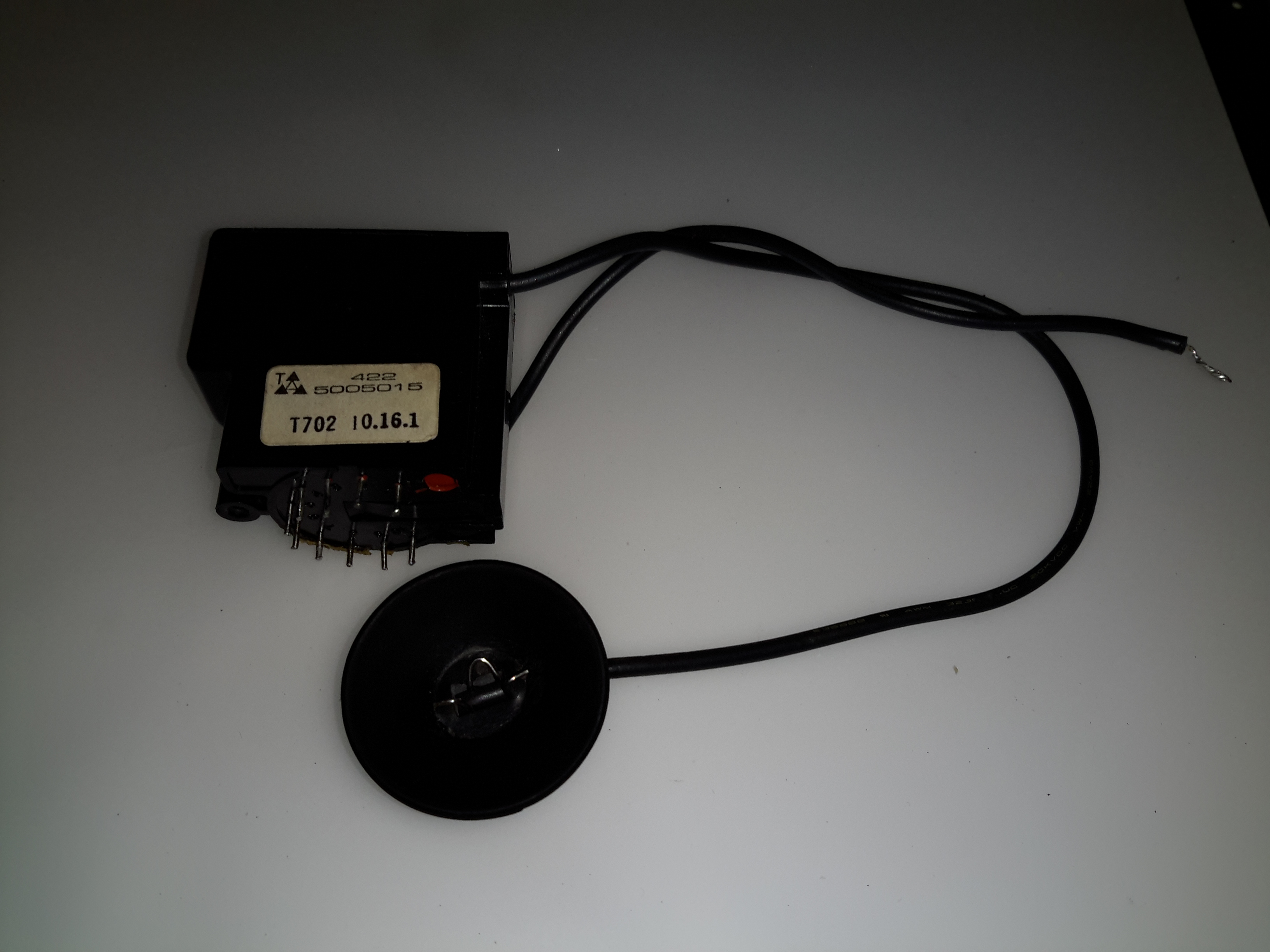
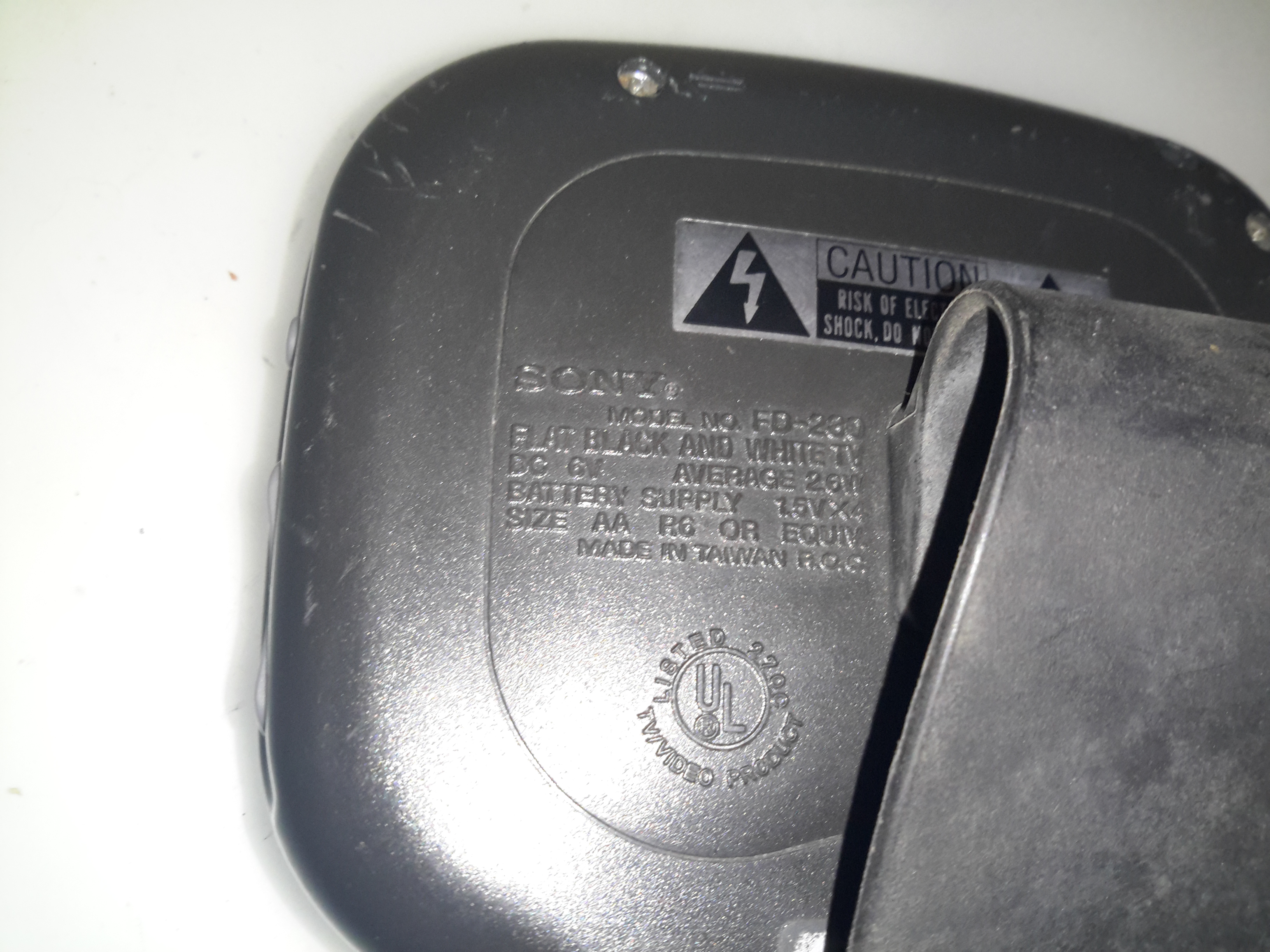
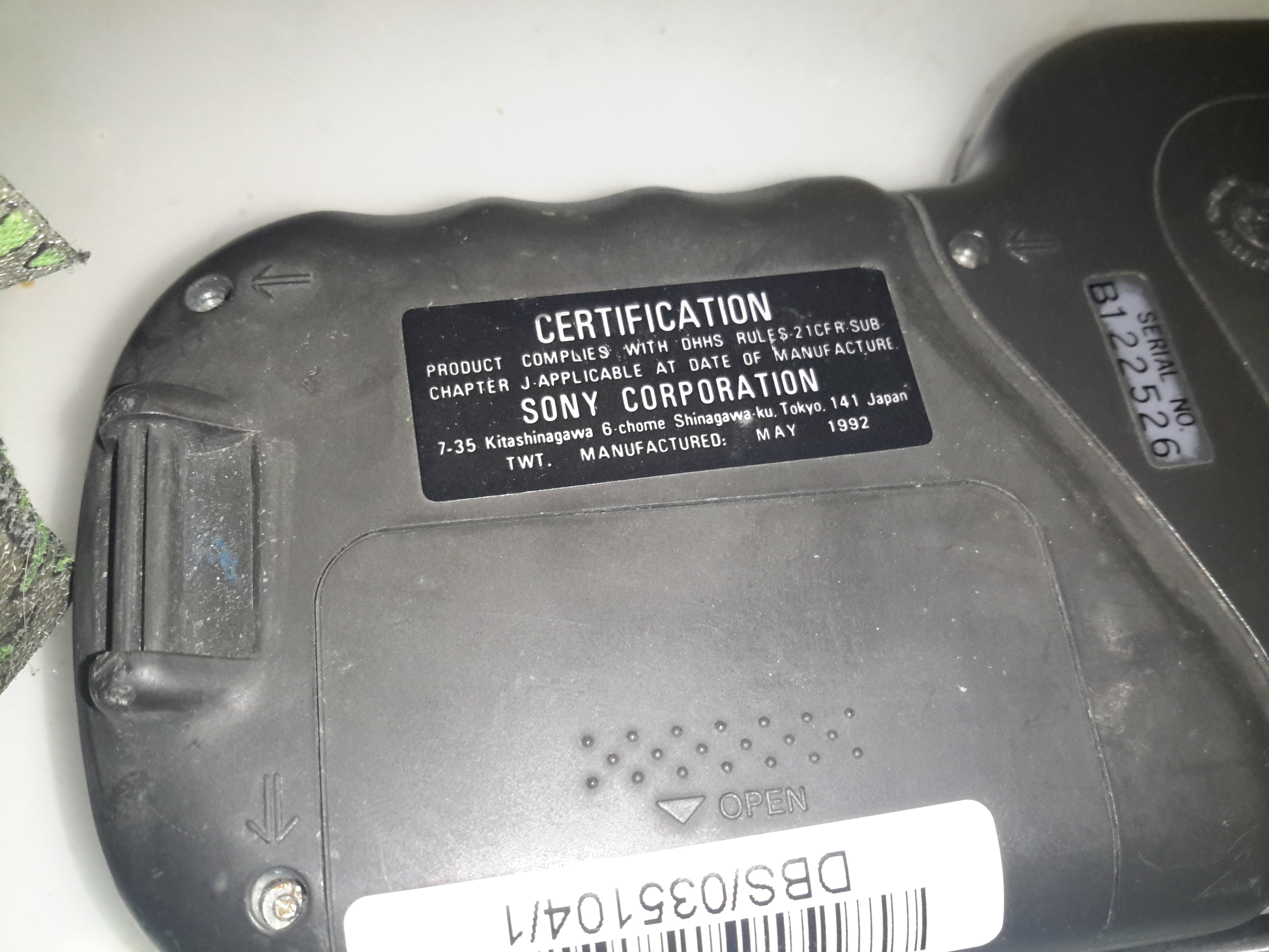
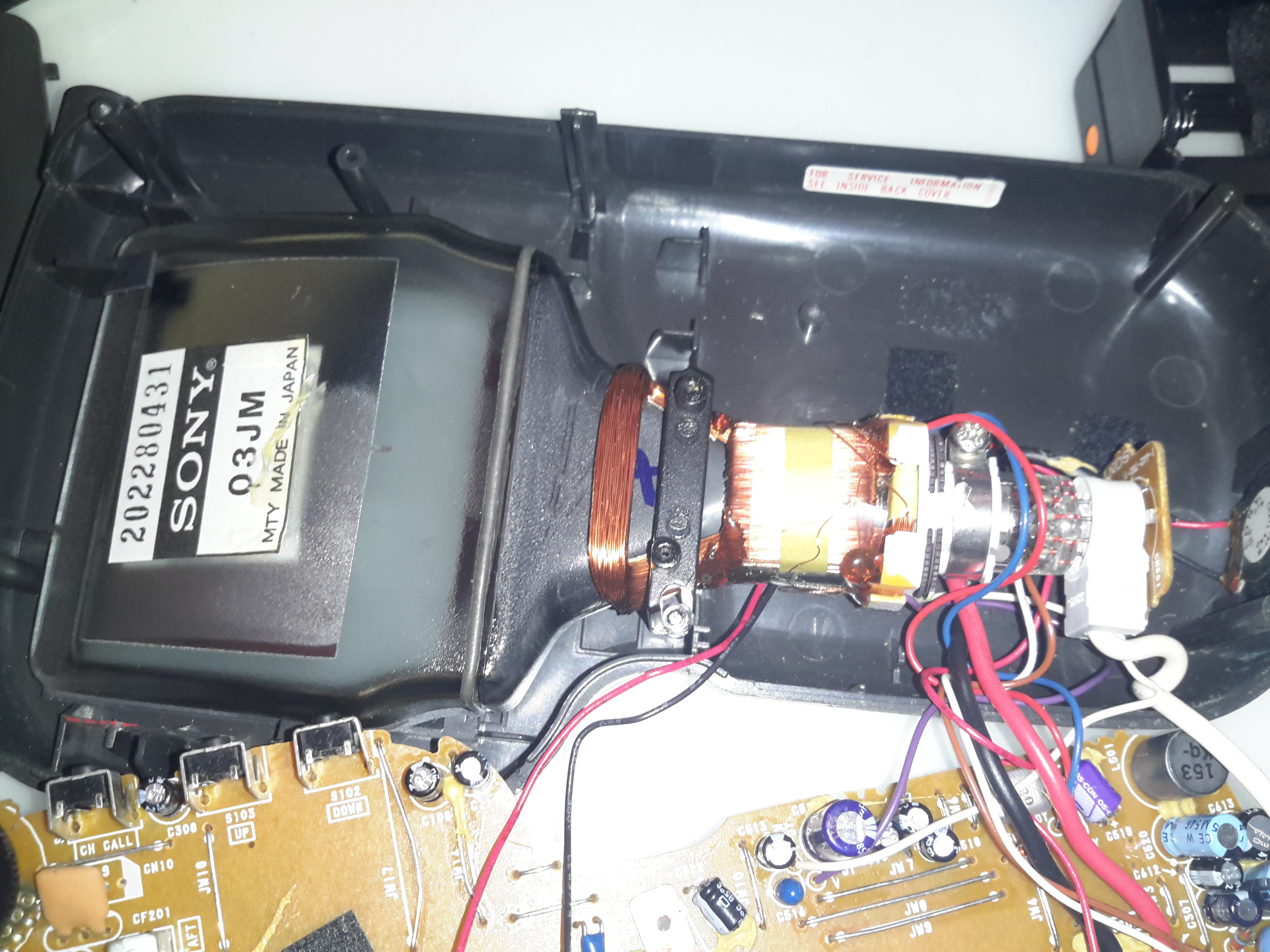
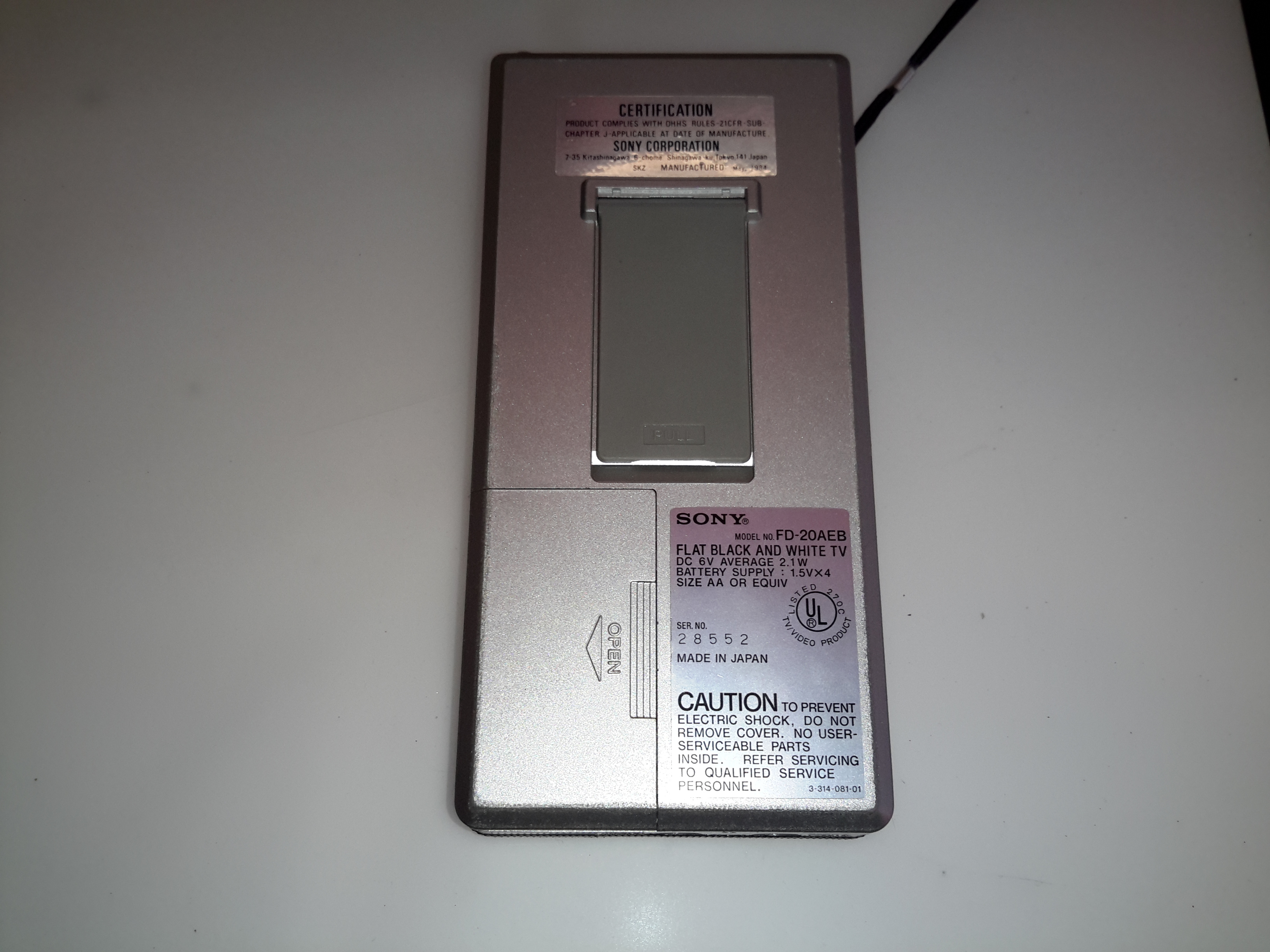
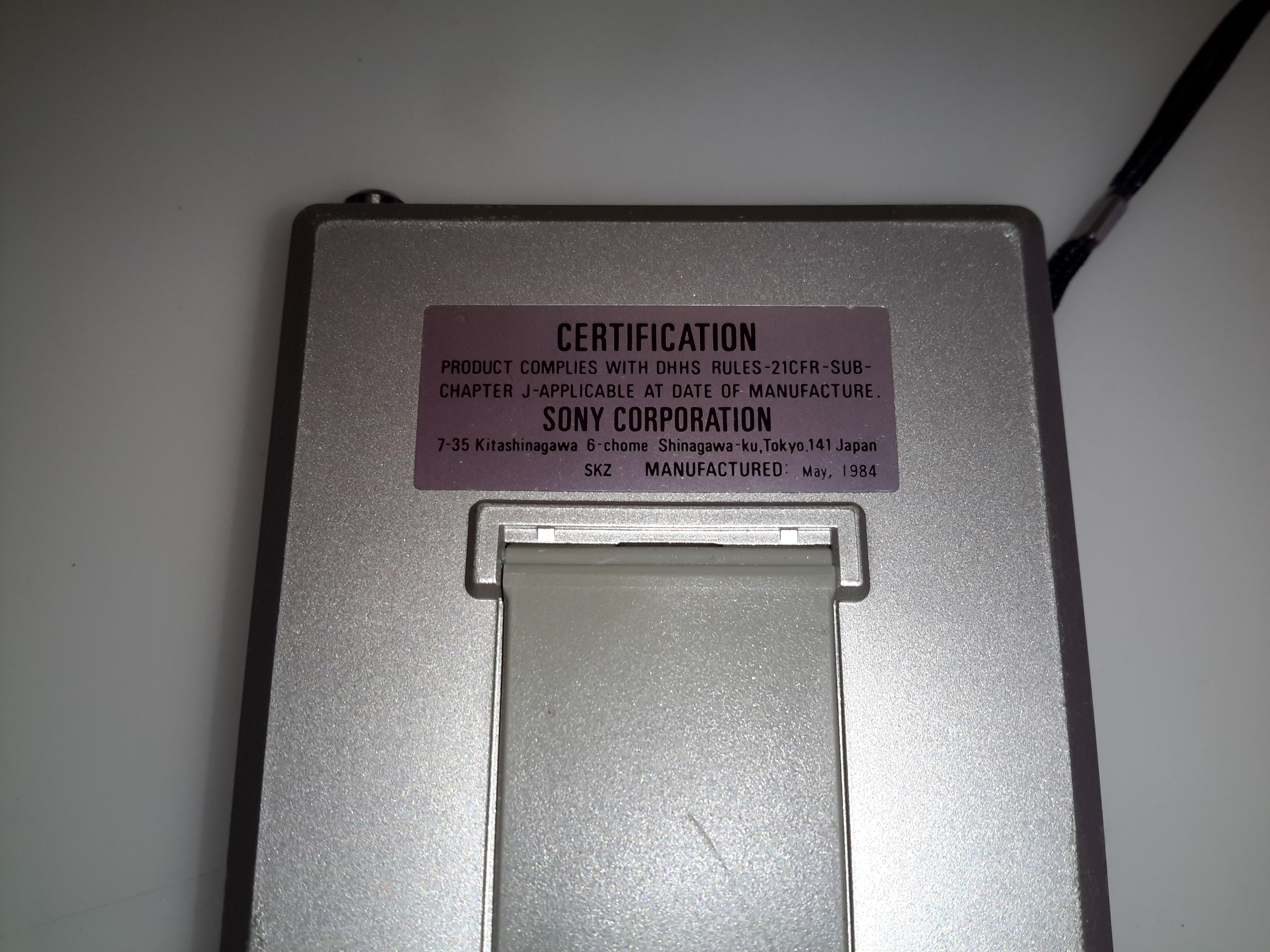
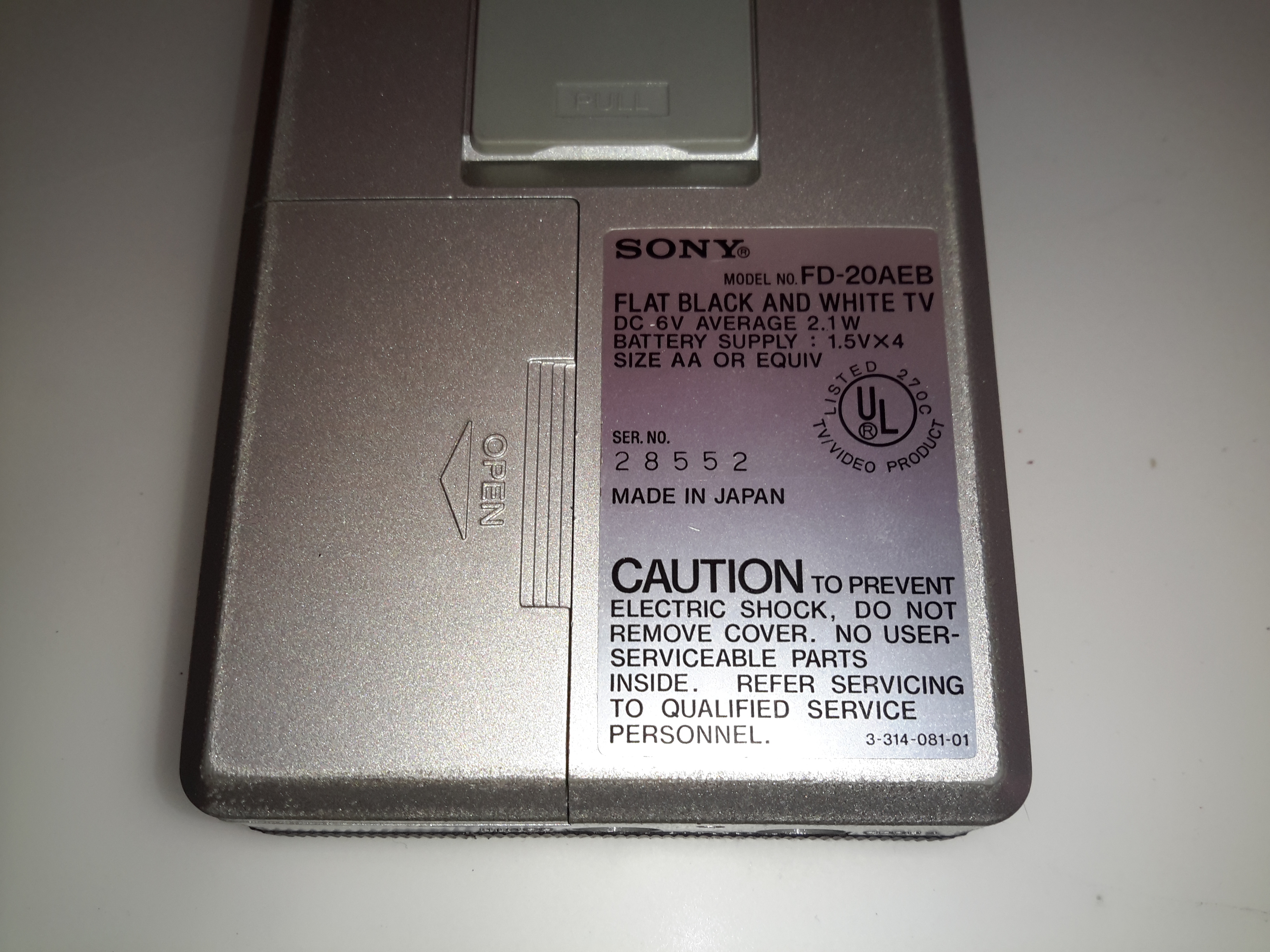
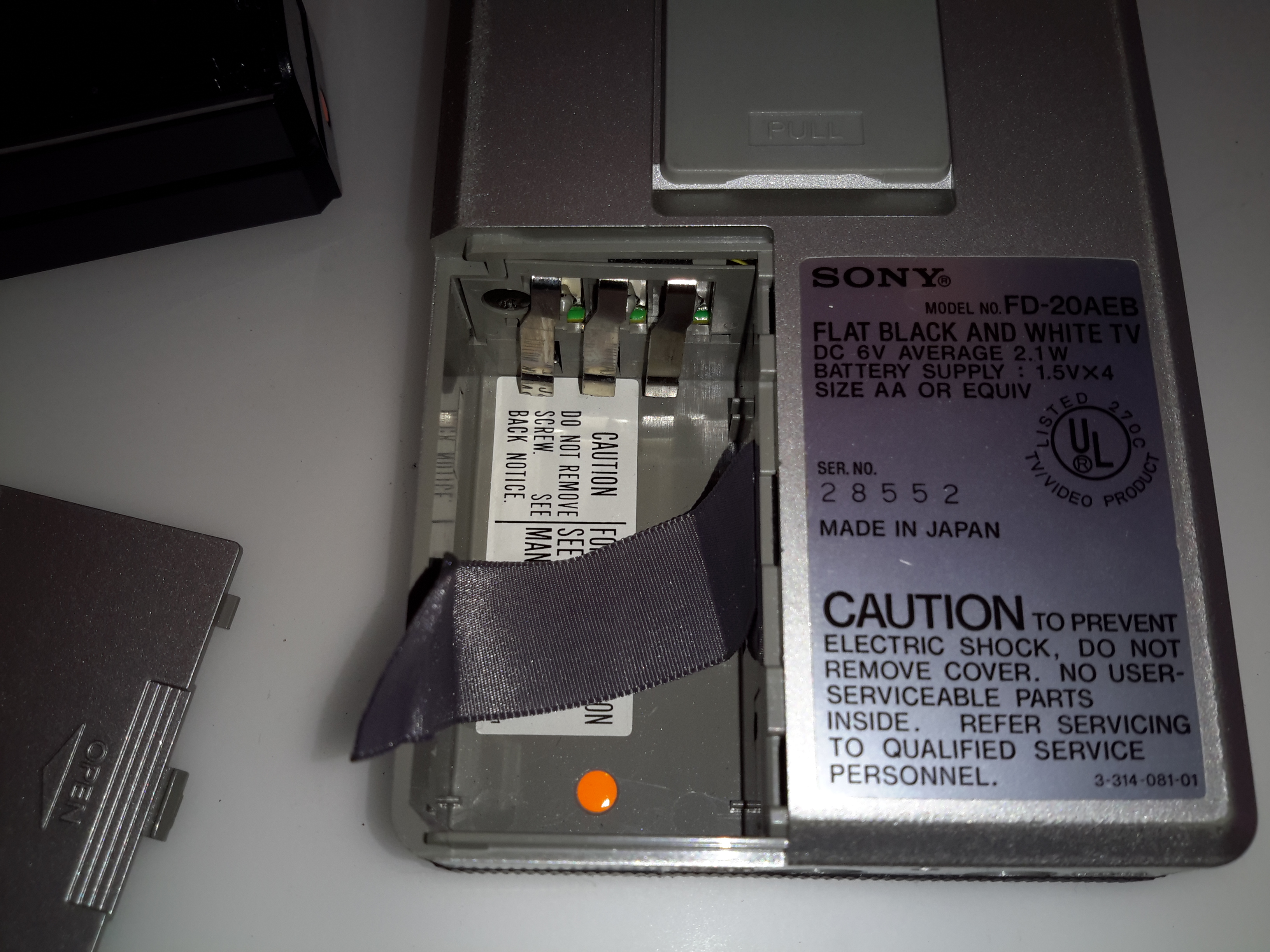
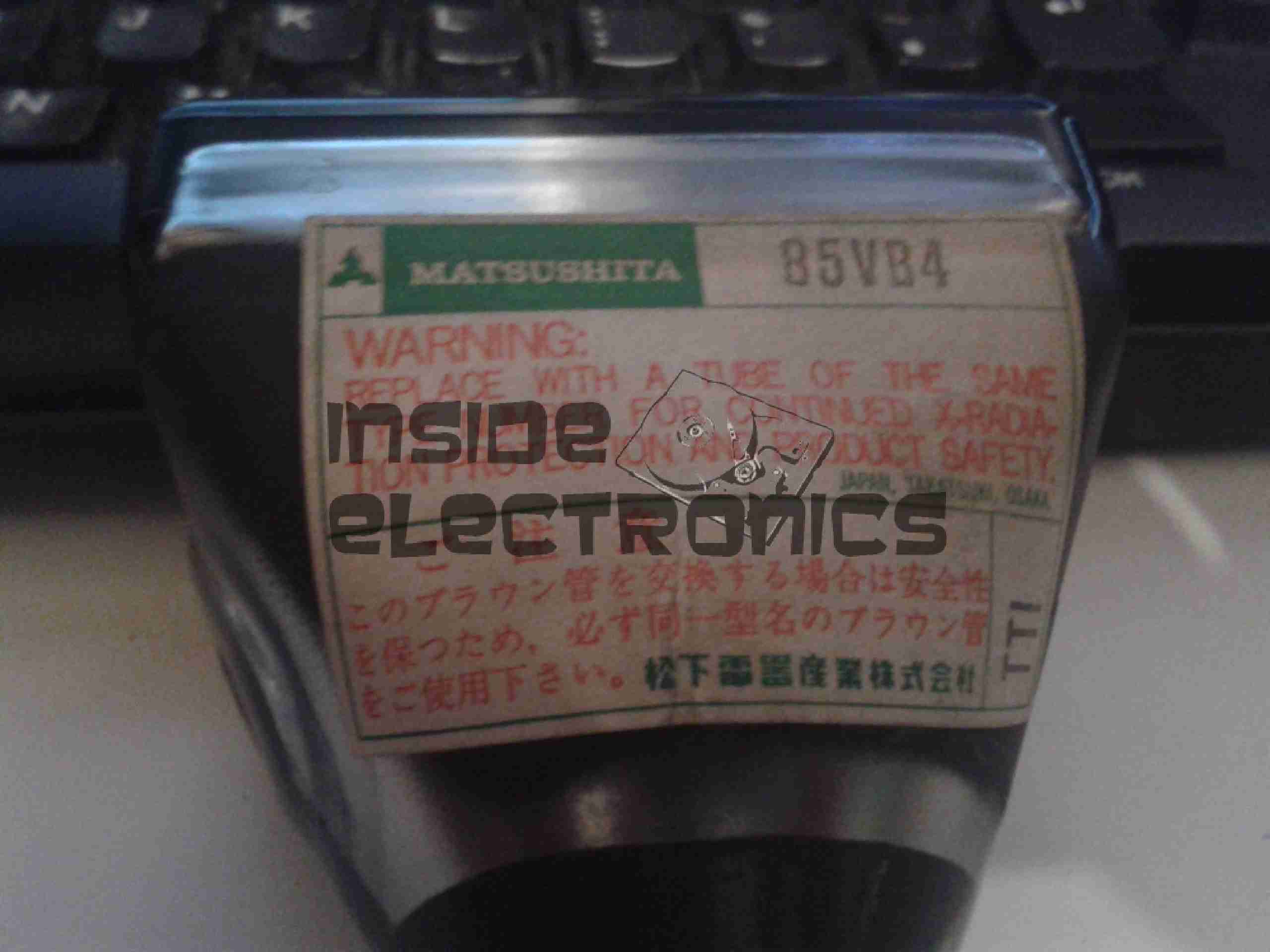
There’s lots of information on the bottom label of this unit, including a notification in German that the X-Ray emission from the device is shielded, and the maximum CRT acceleration voltage is 8kV. This last point is a bit strange, since the 40CB4 datasheet states a maximum design voltage on the final anode of 6kV. I did measure the voltage at the anode cup, and it’s stable at 7.15kV!

Internal Overview
Internal Overview

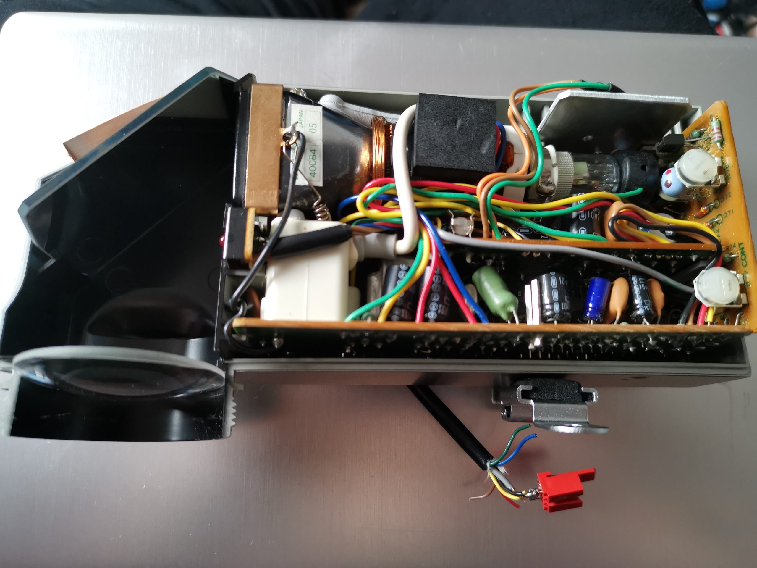
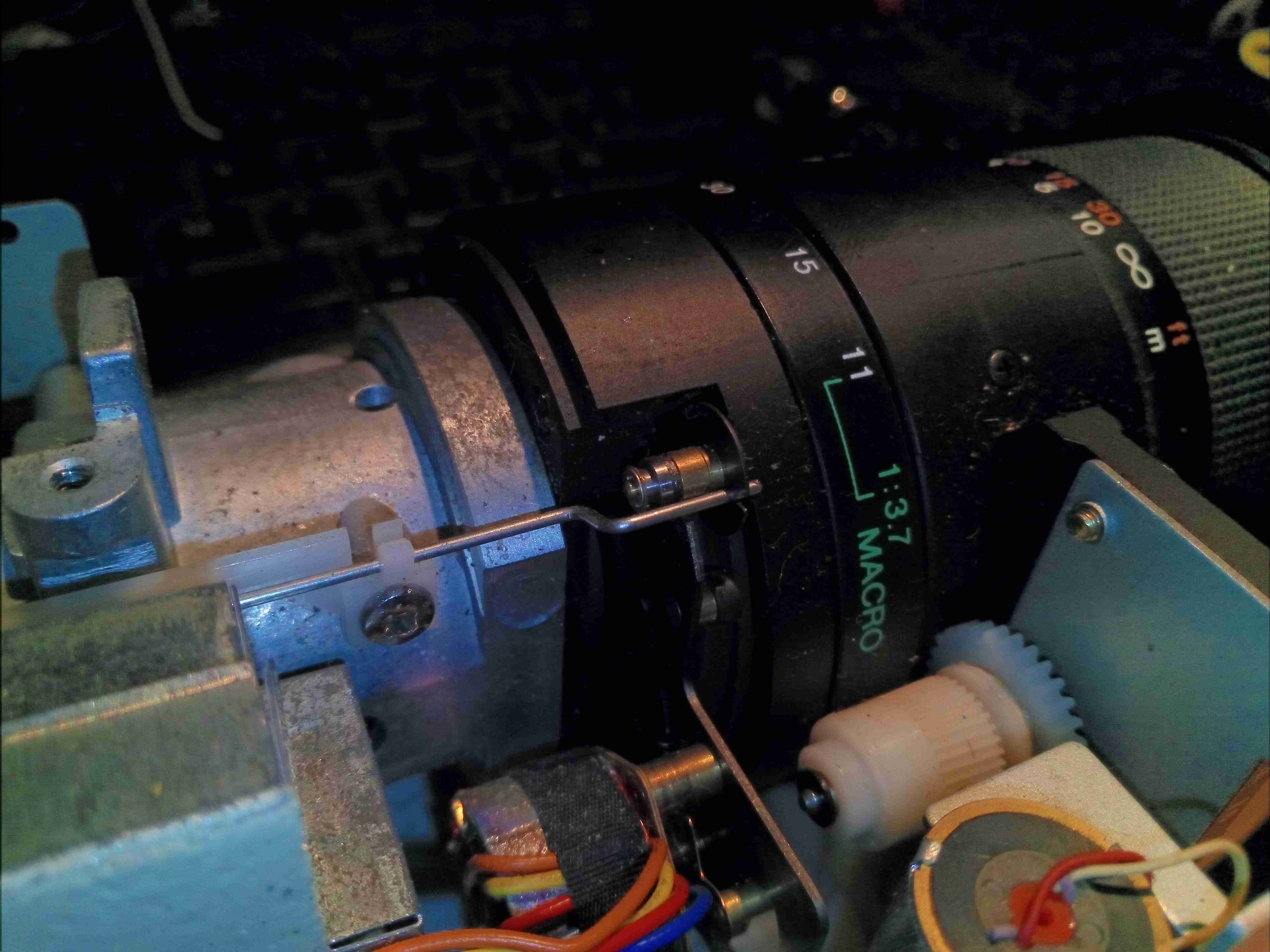
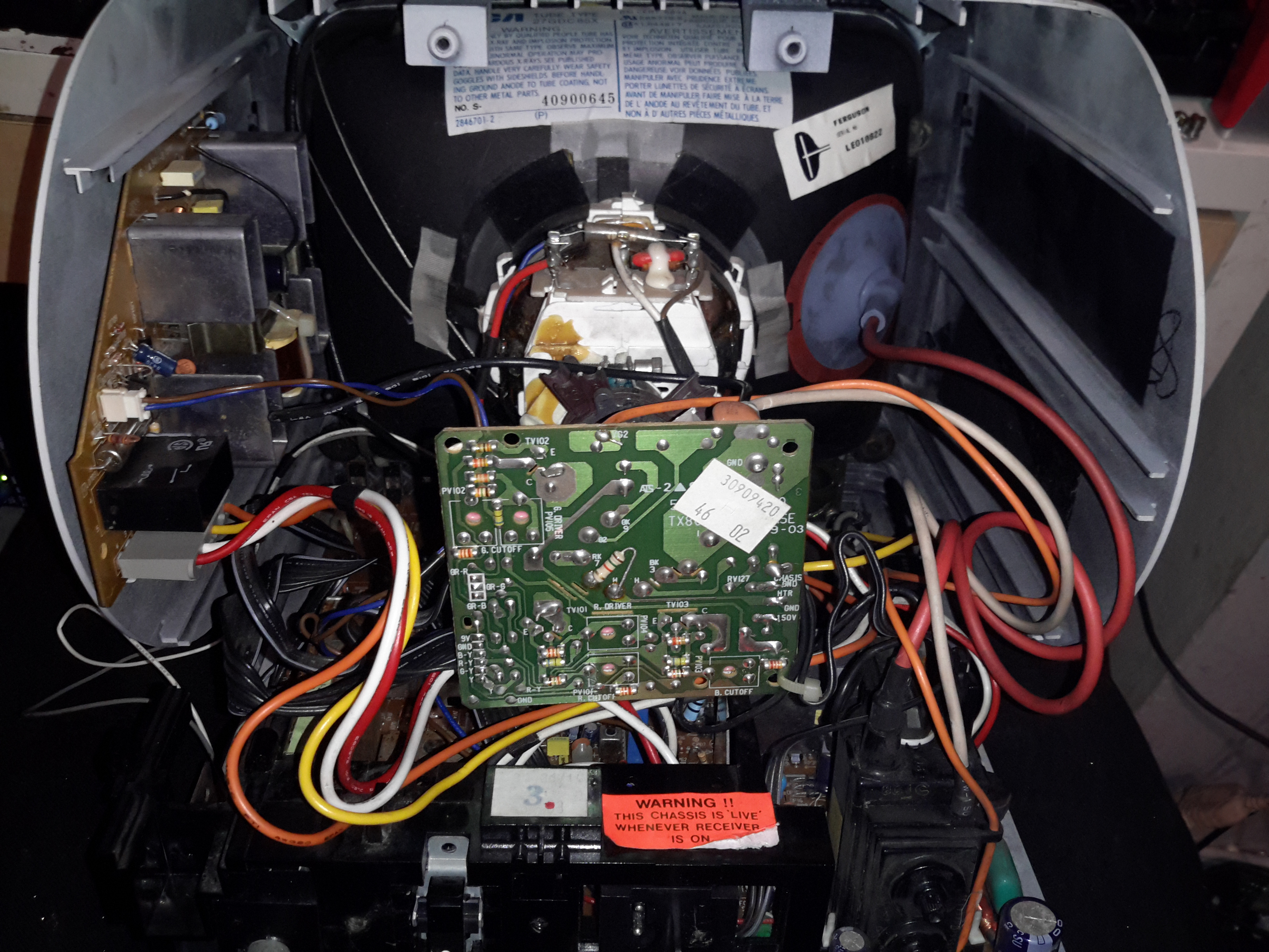
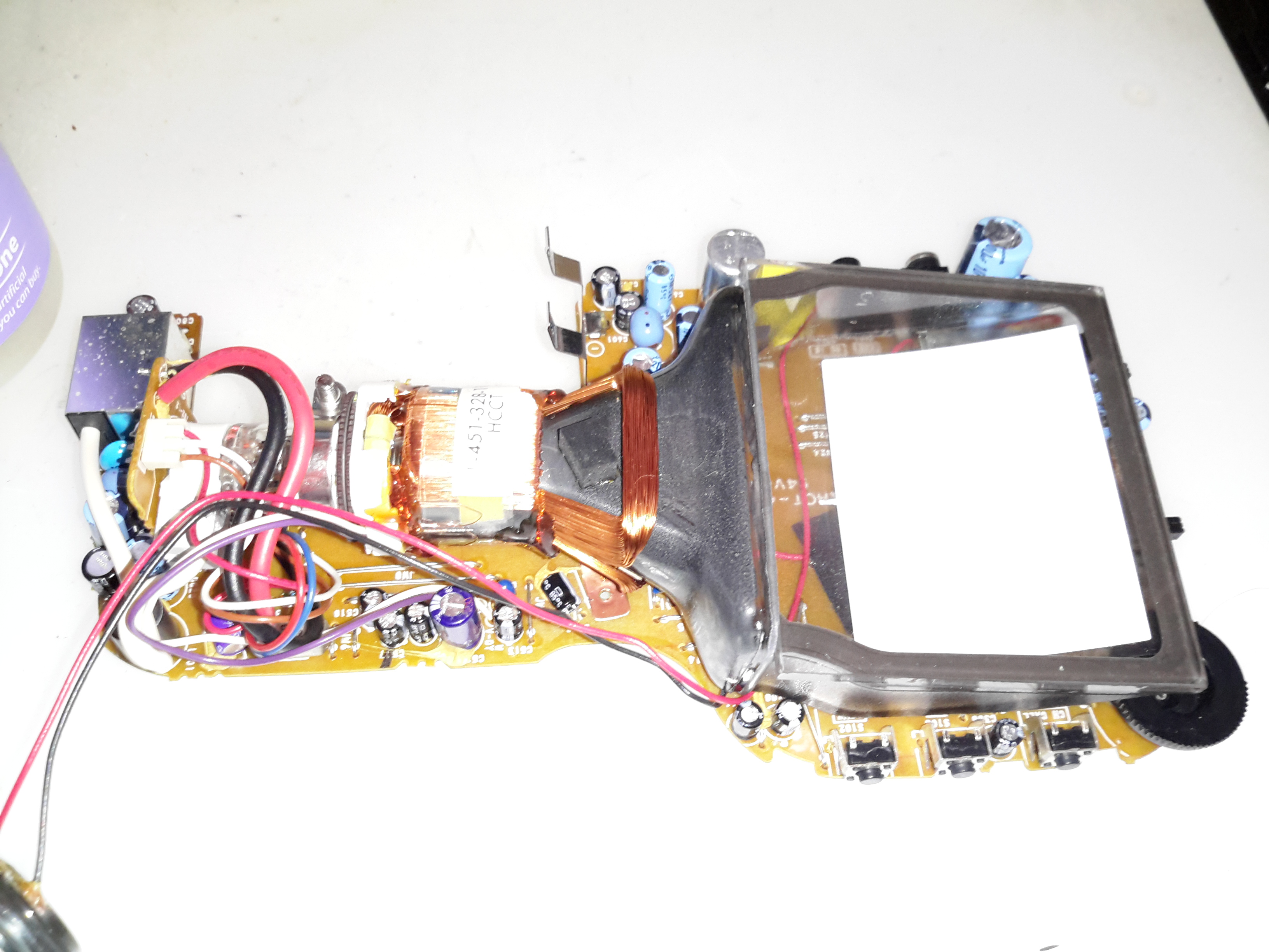
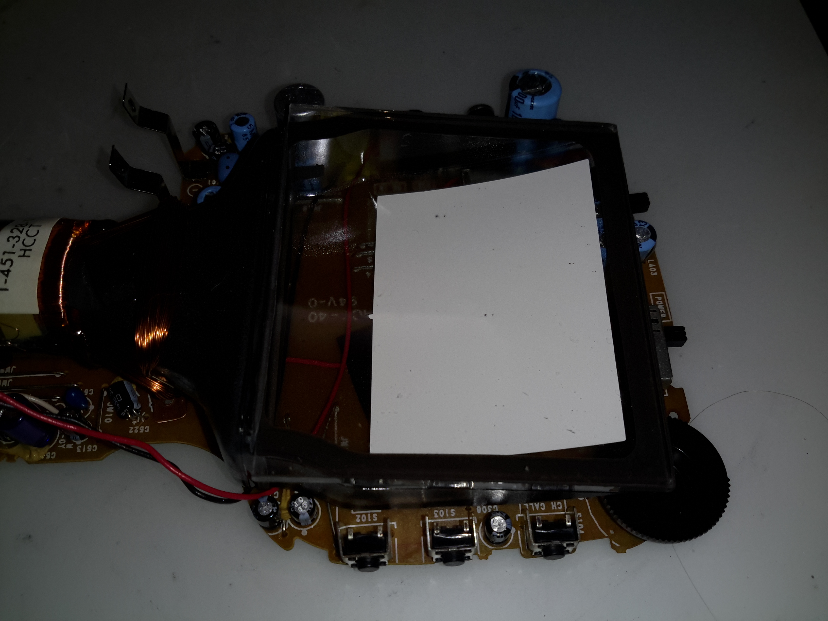
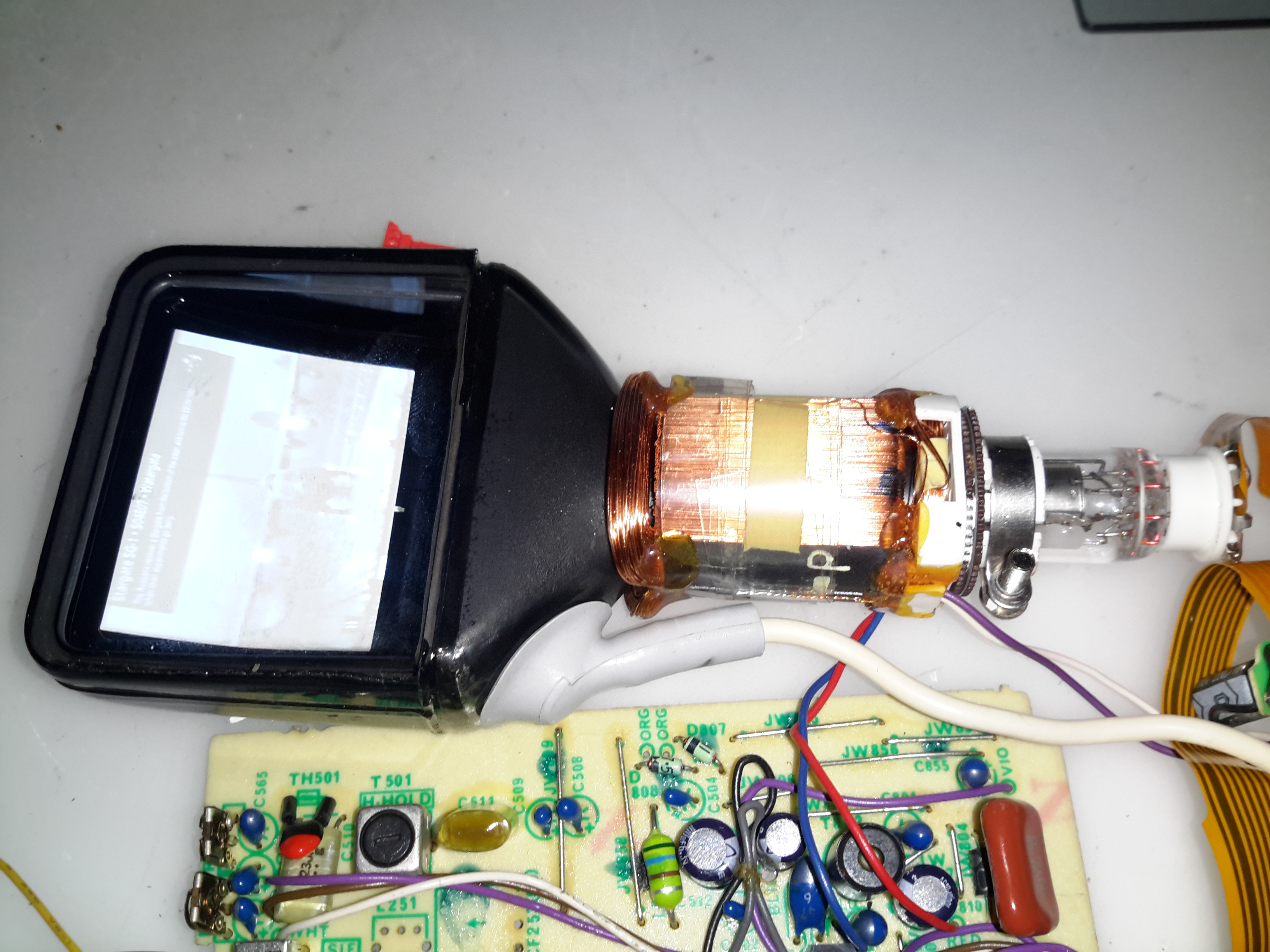
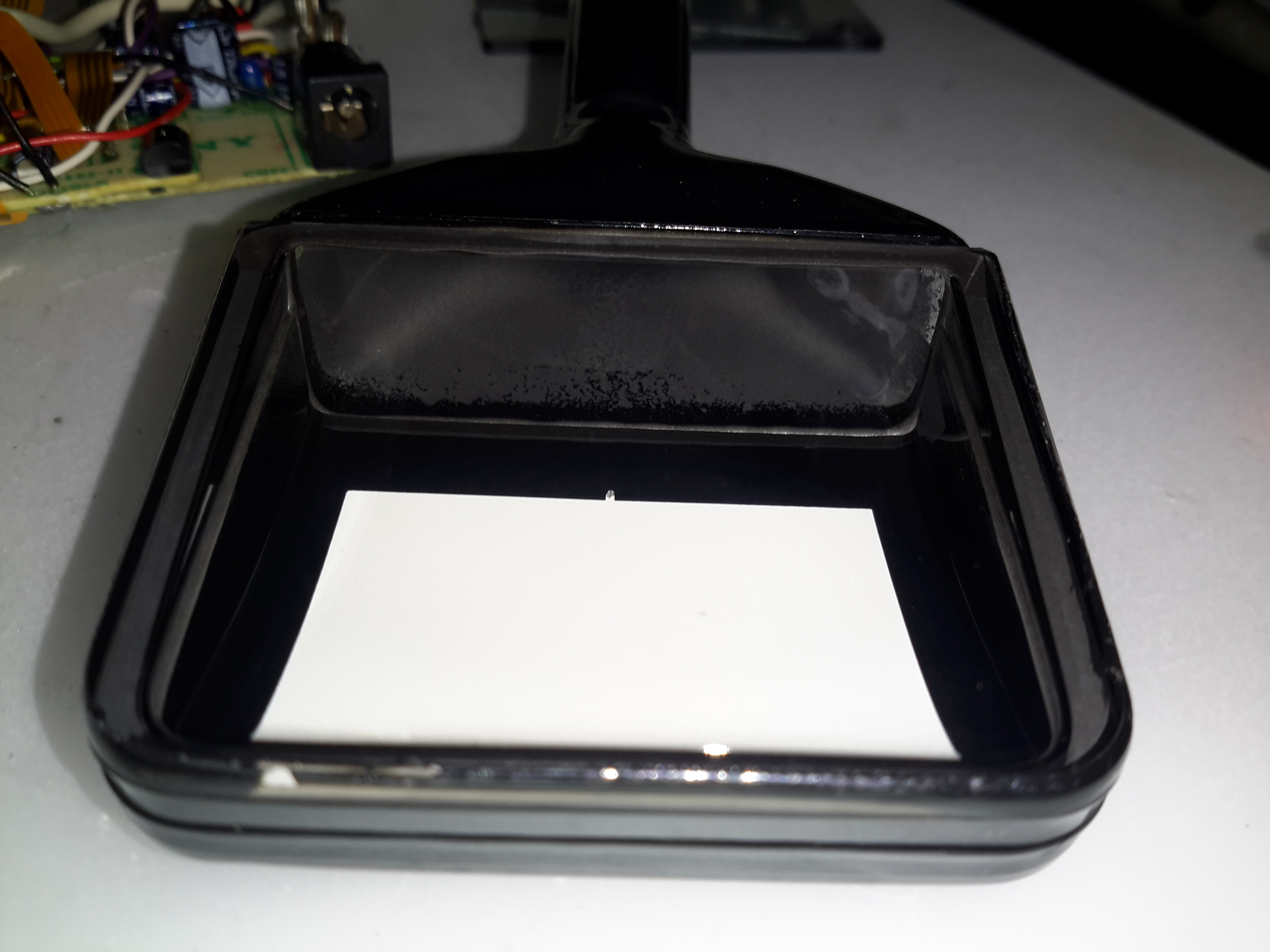
Popping a couple of screws out & removing the enormous eye cup allows the top cover to come off. This unit is very tightly packed inside, with 3 PCBs! The magnifying lens (~45mm diameter) & mirror on the left enlarge & turn the image so the camera operator can see it. The CRT’s at the top, with a copper grounding band around the face.

CRT Face
CRT Face

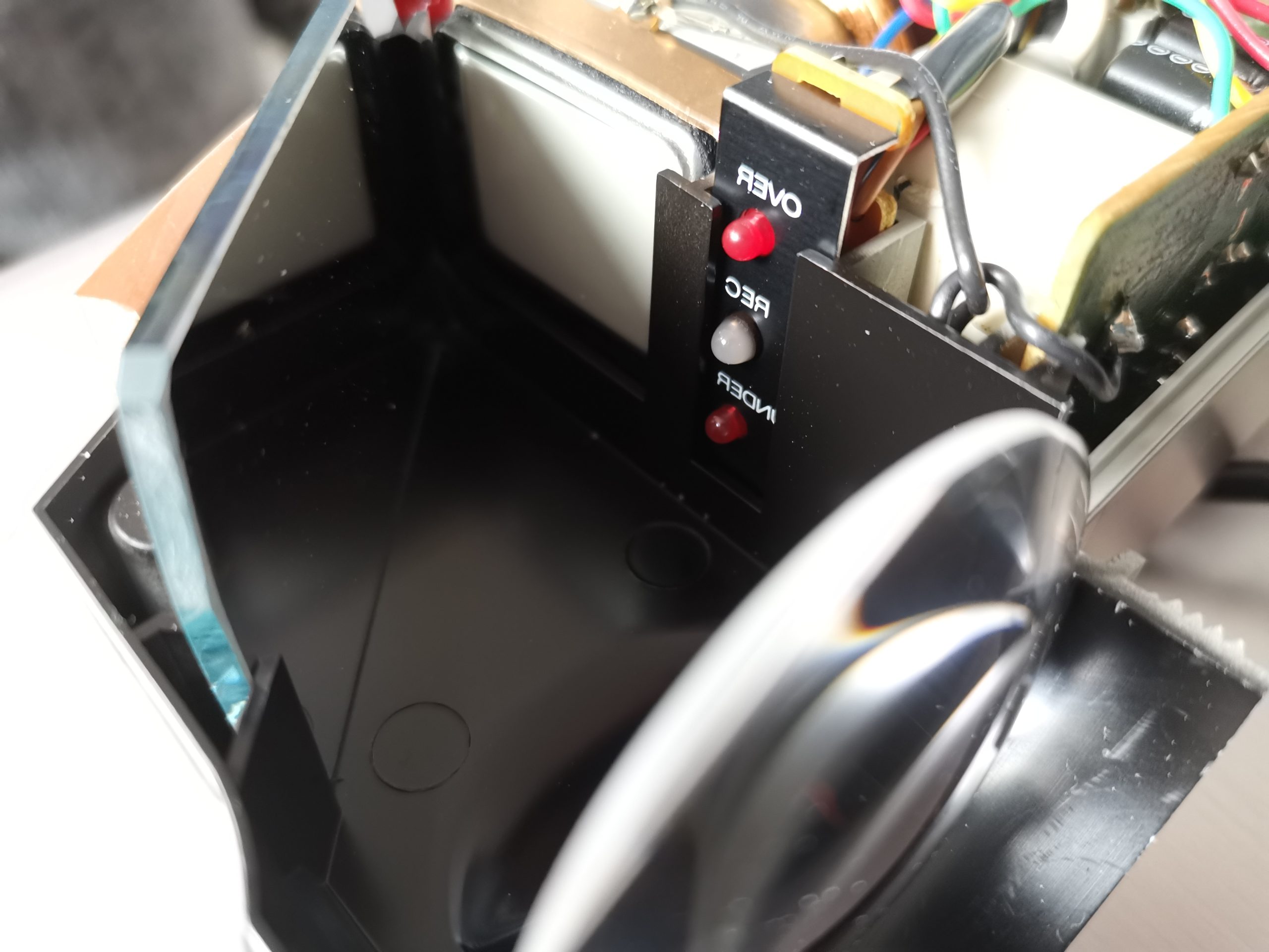
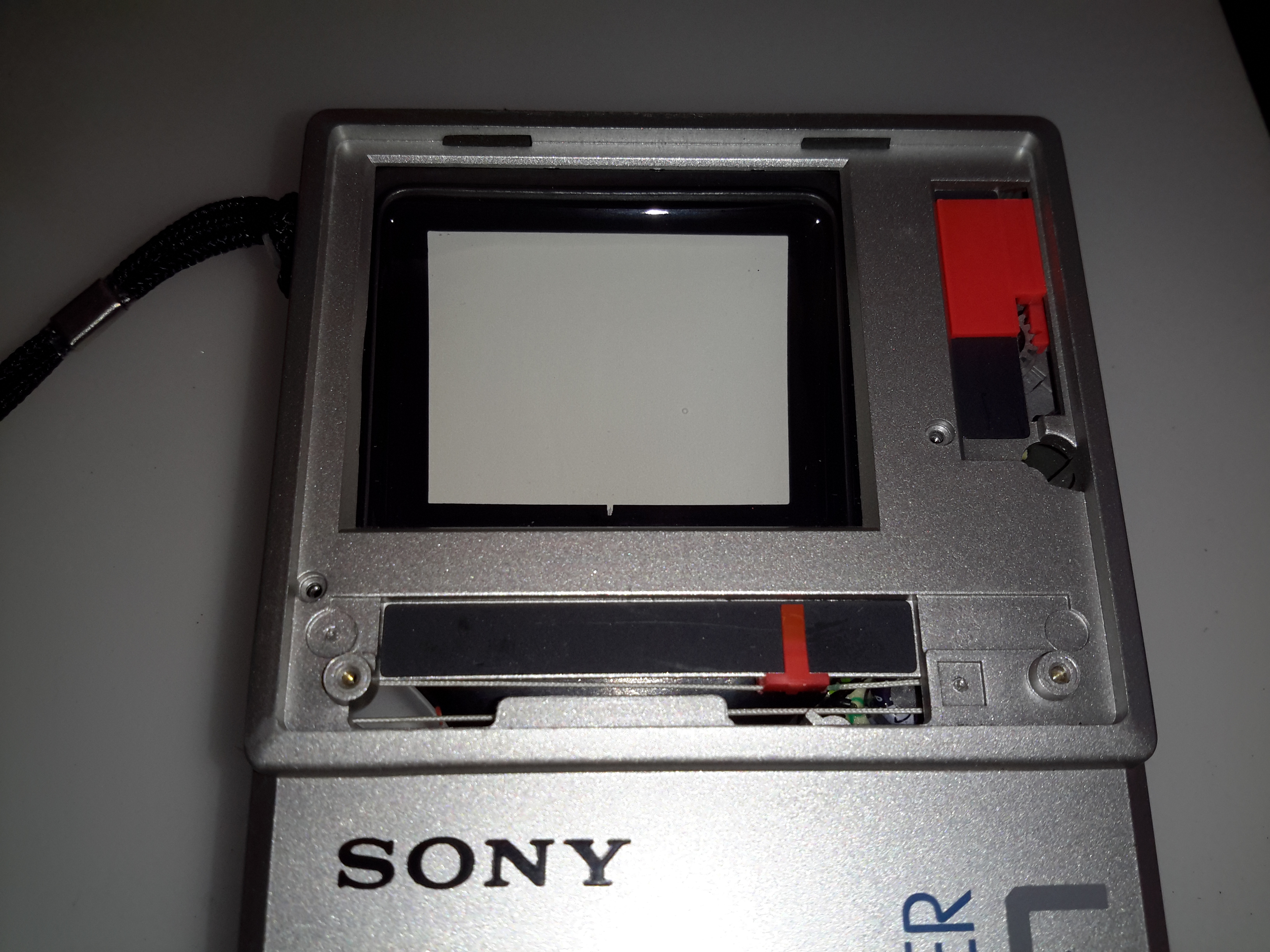
The CRT face is neatly slotted into the plastic housing, with the tally LEDs to the right of it. The legends on the LEDs are naturally printed in reverse, since they’re intended for viewing through the mirror. The optical section is entirely spray painted black for better contrast & stray light control.

Electronics Area
Electronics Area

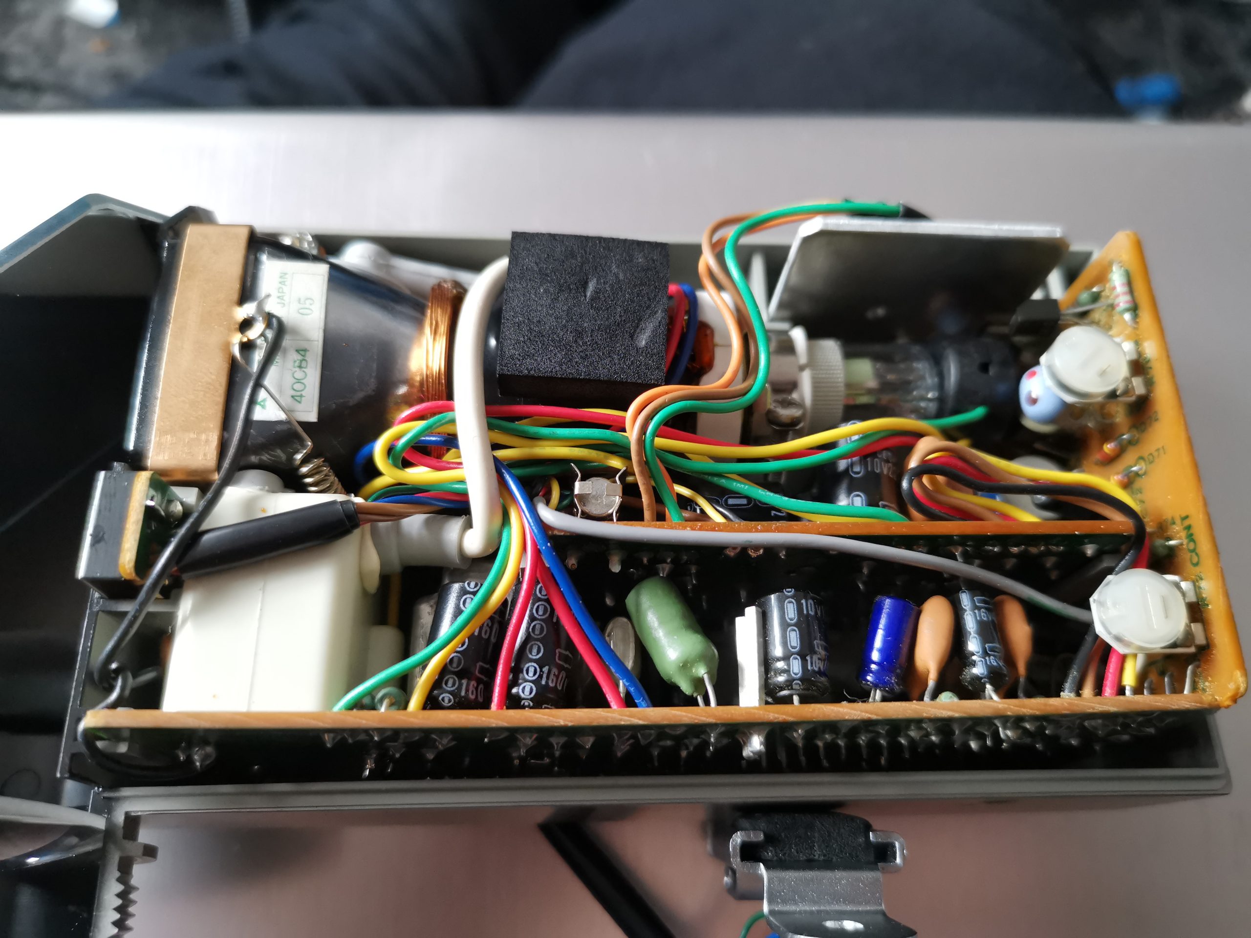
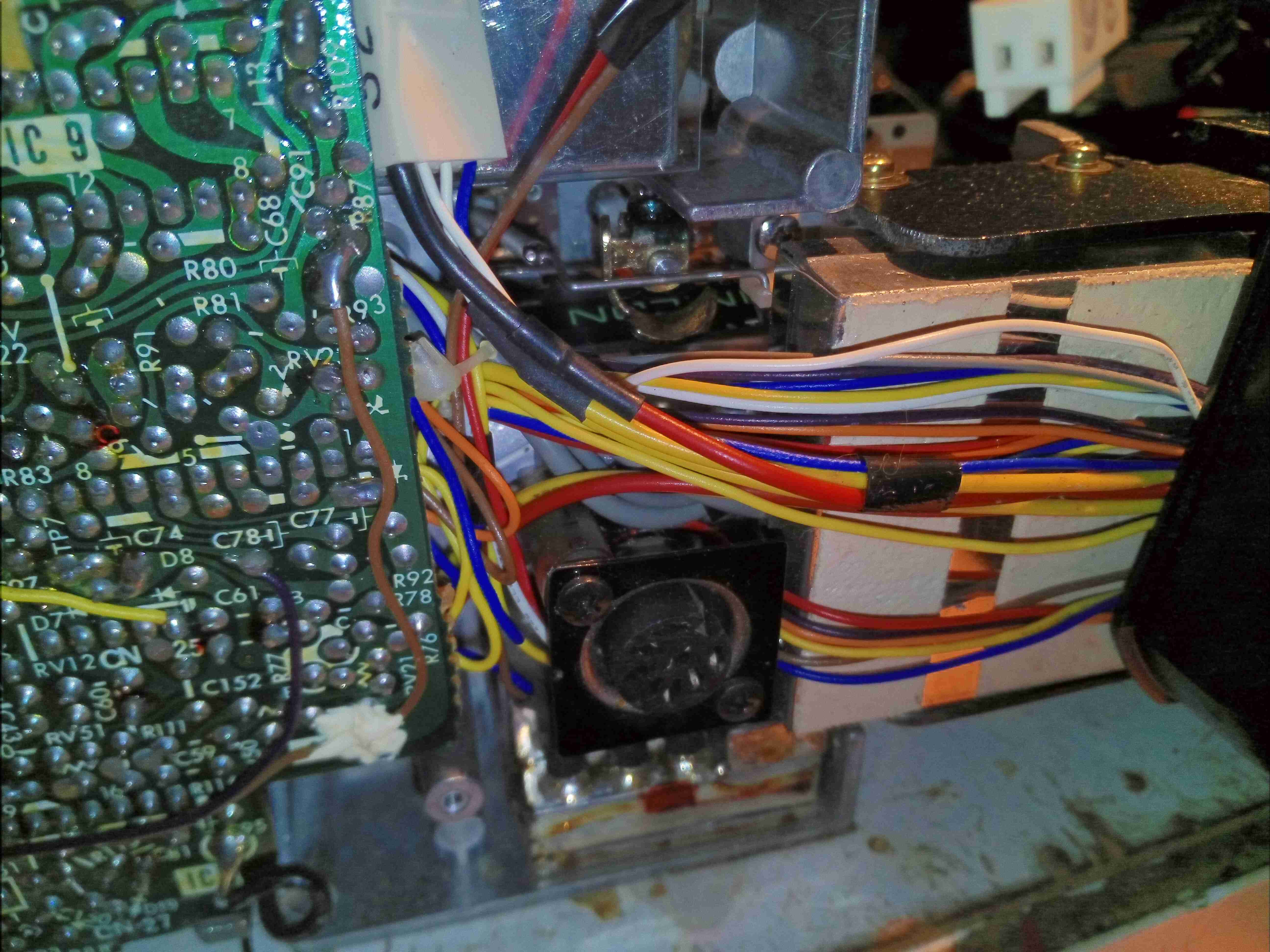
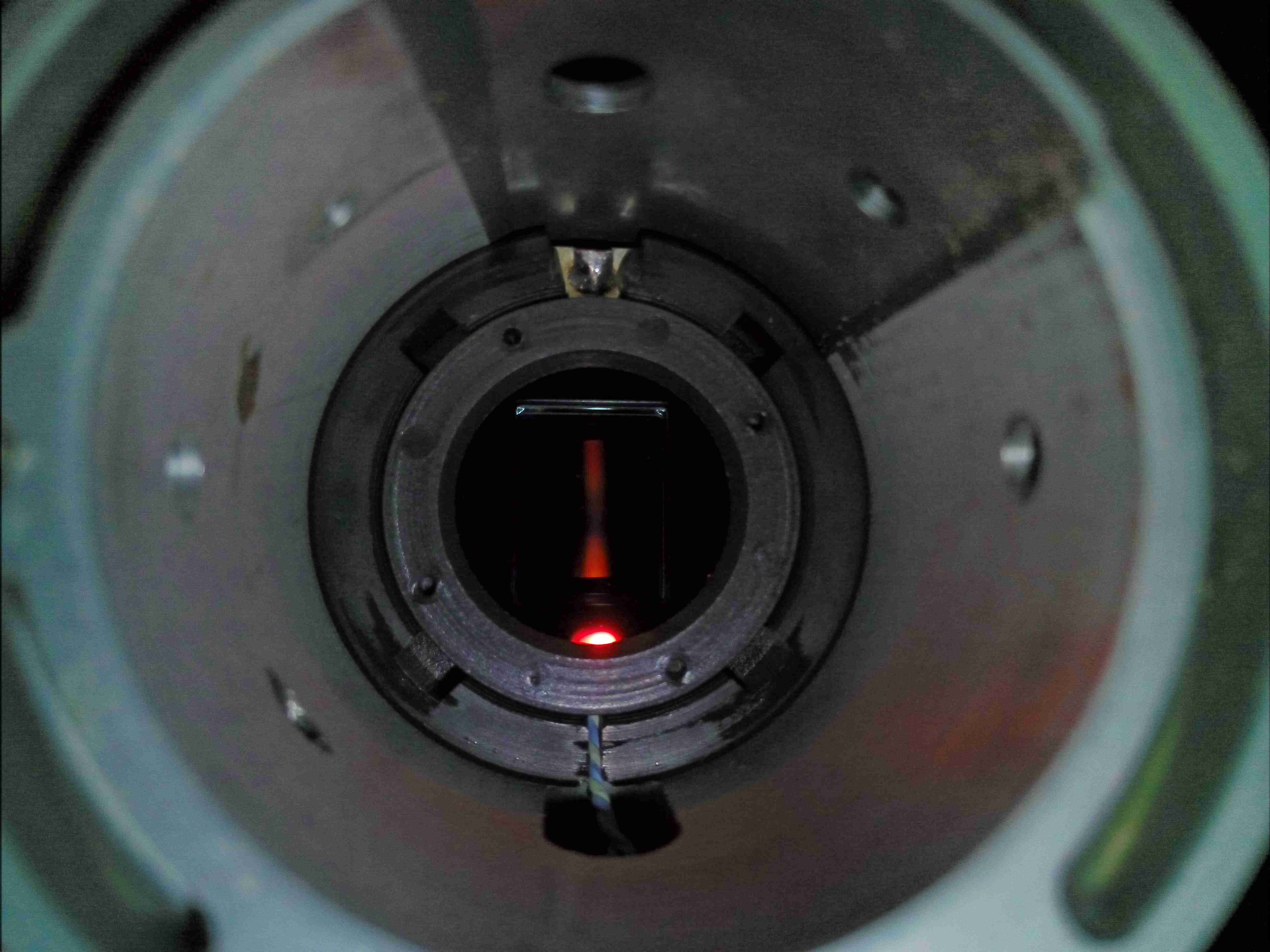
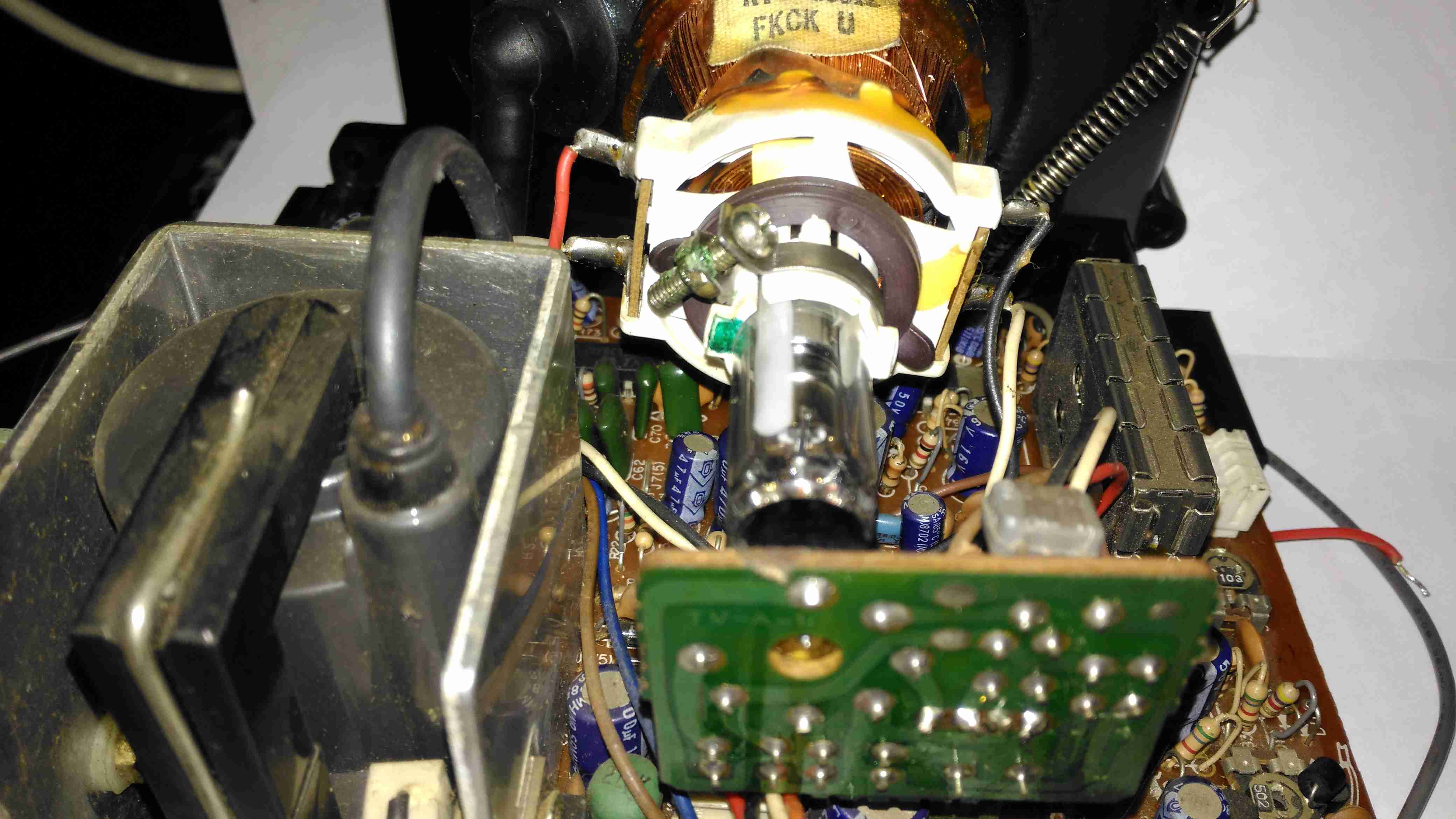
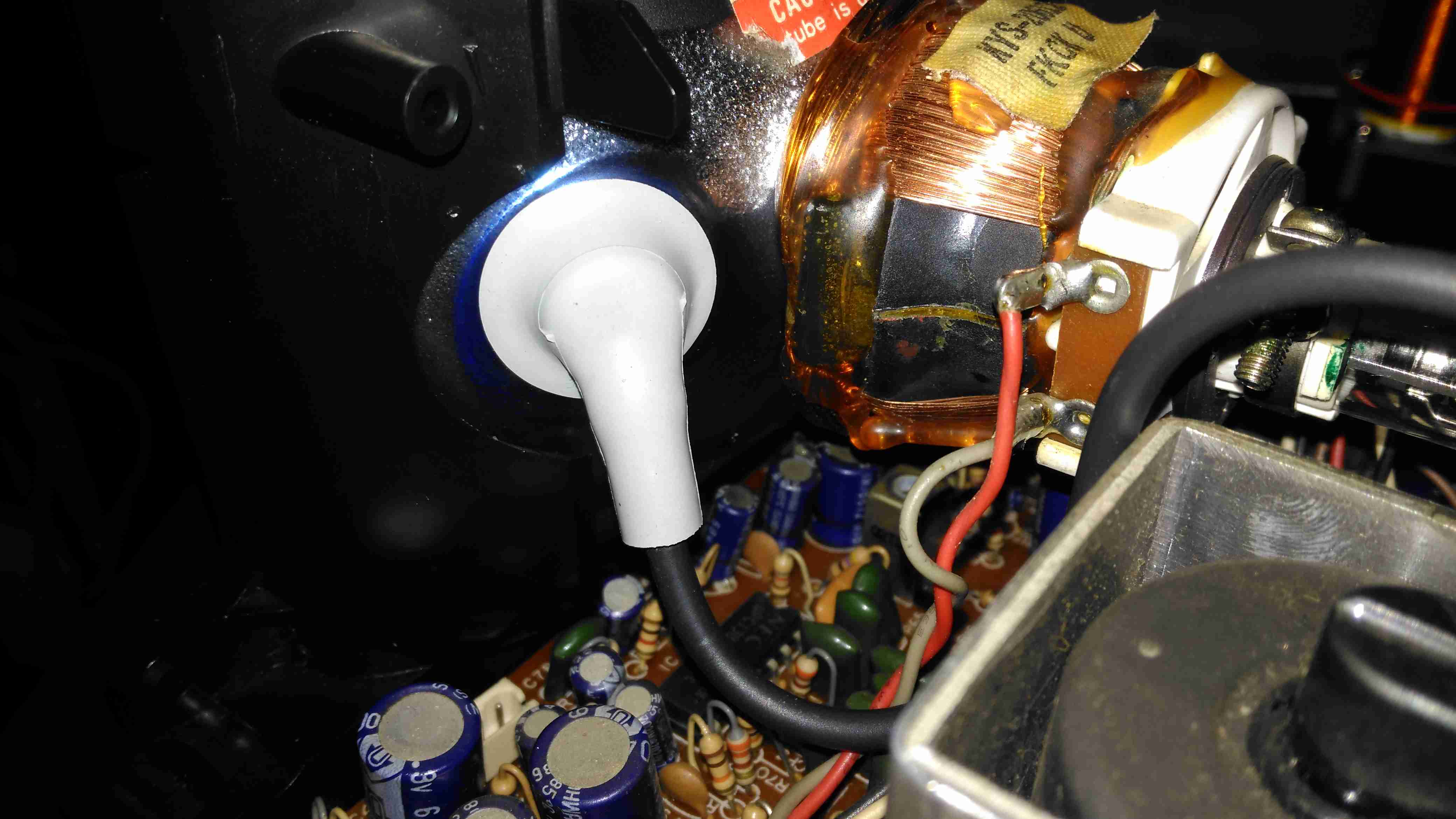
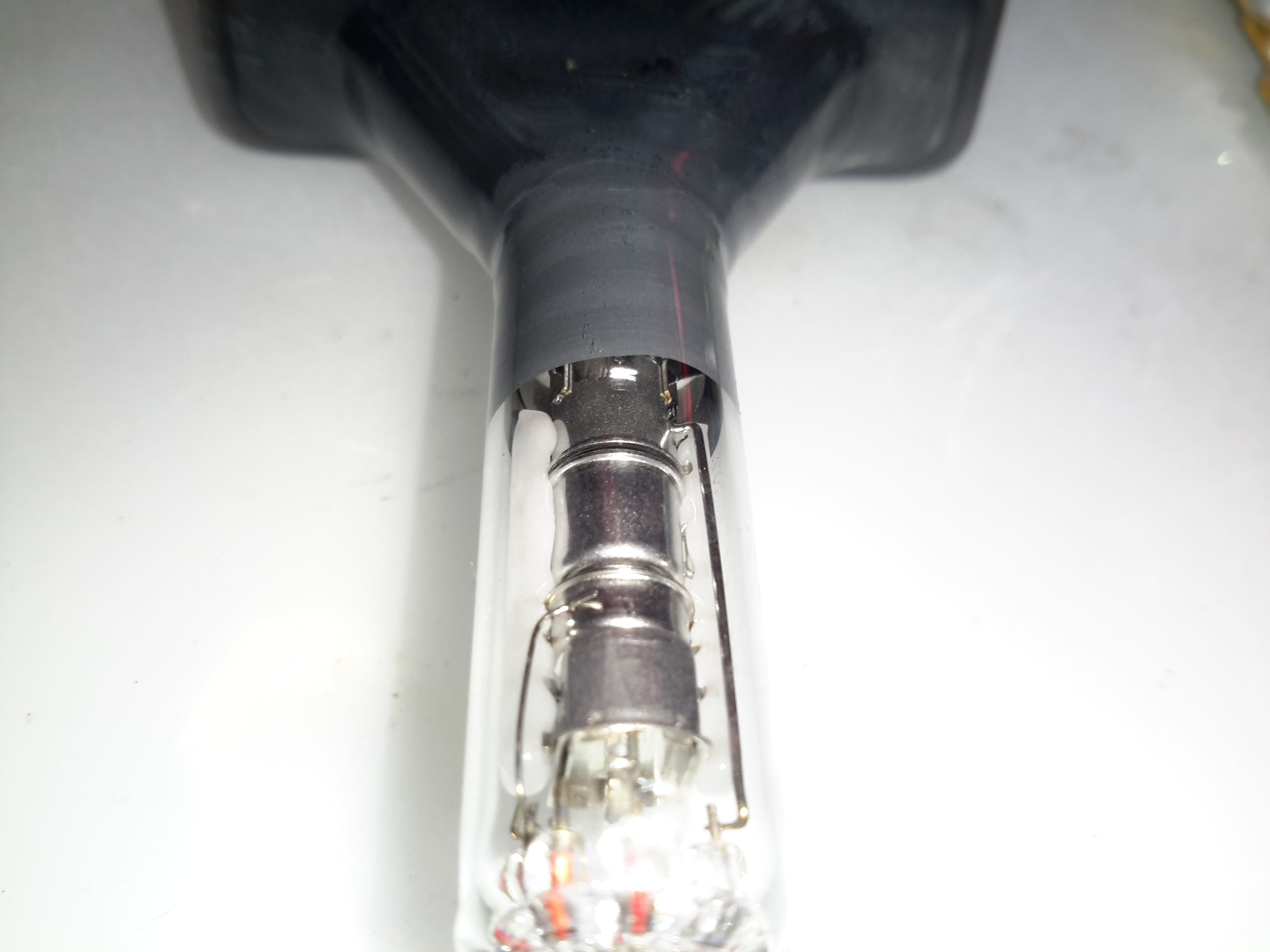
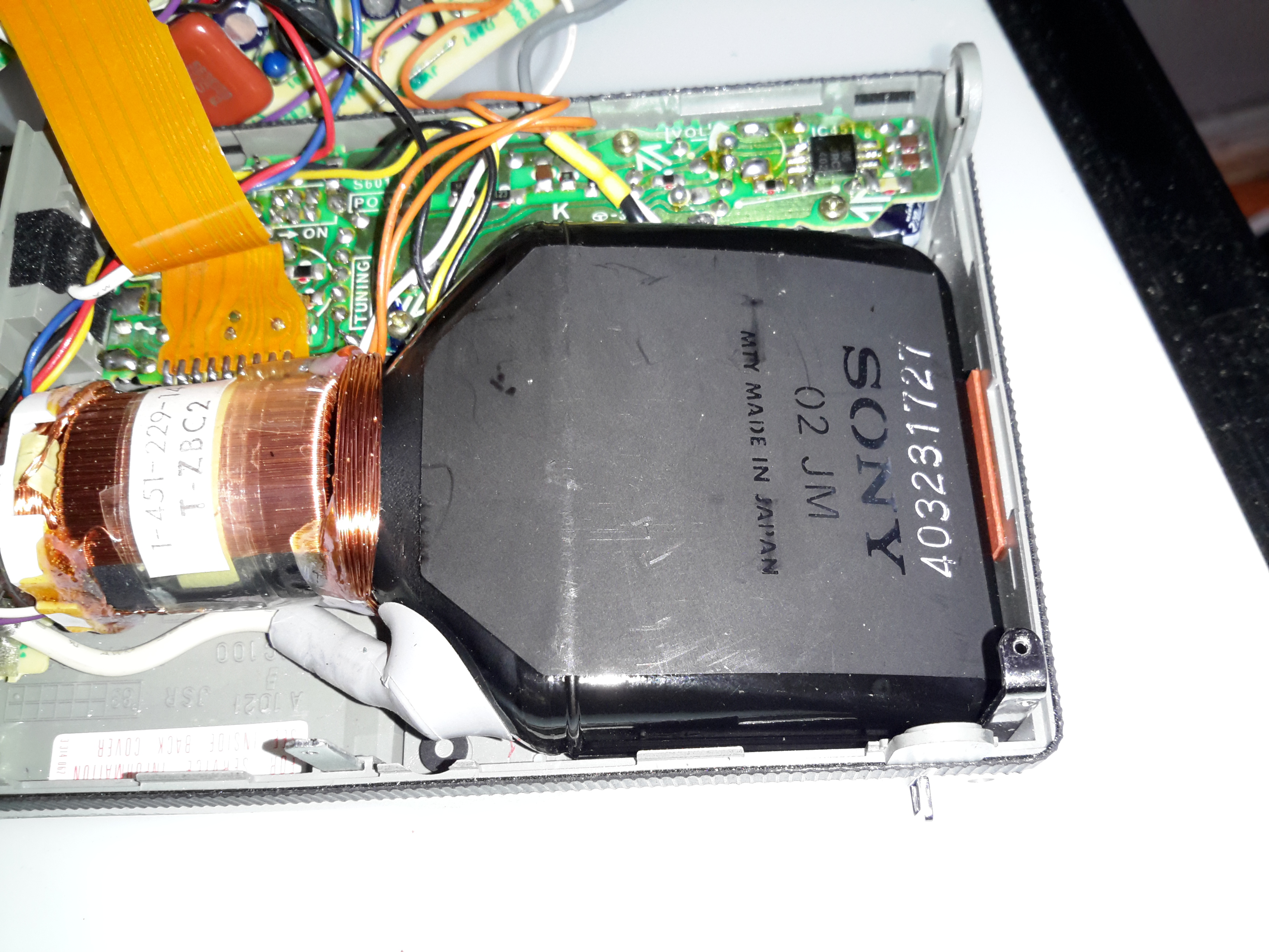
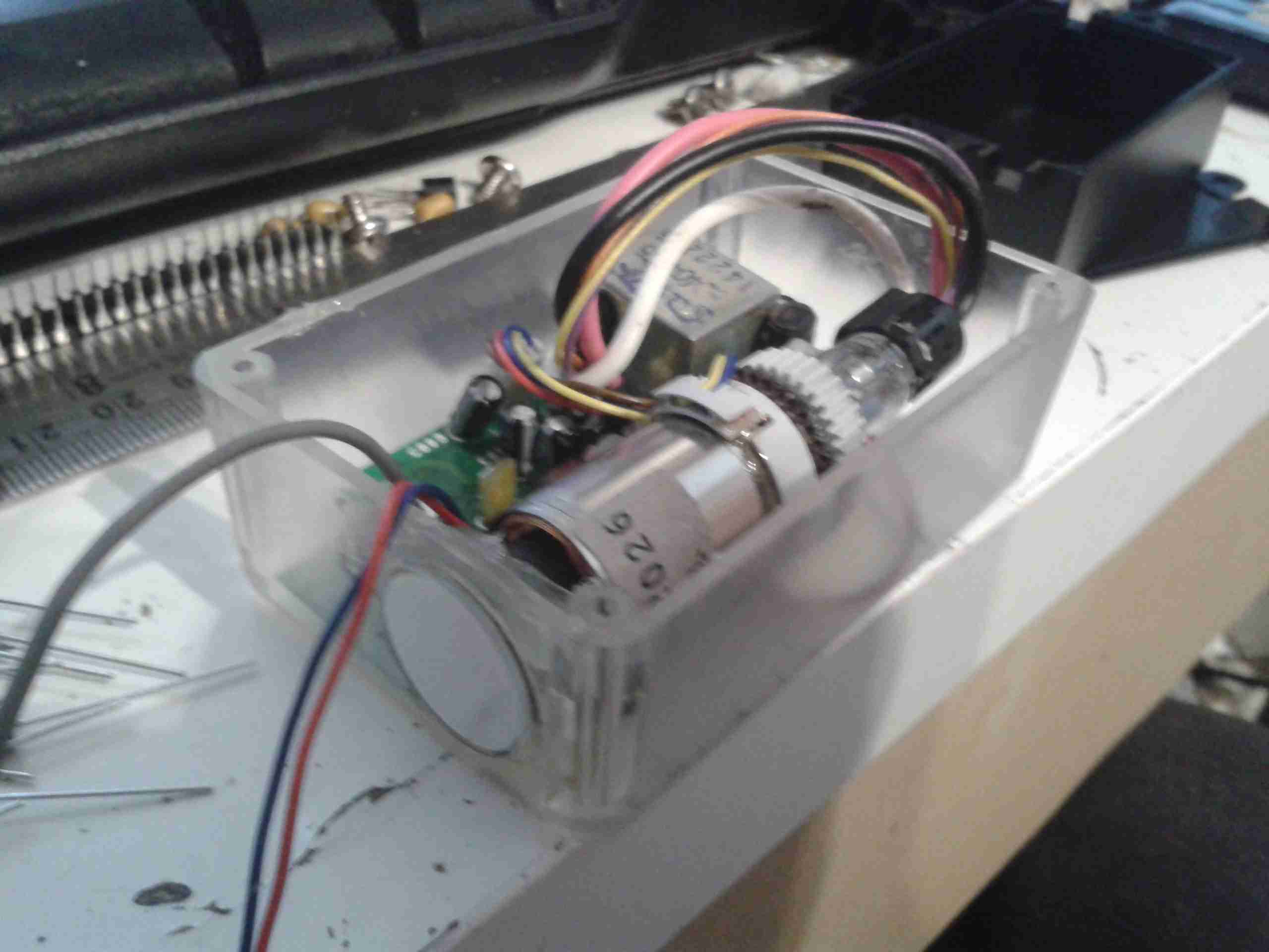
The other 5″ of the casing is packed with electronics to support the CRT. The bottom PCB even “wraps around” to the right, with copper staples connecting the boards together. The CRT tube itself is hiding inside the deflection yoke and under a foam pad at the top of the unit. It’s secured in place with a copper grounding strap wrapped around the face of the tube, and a spring. A single screw secures the strap to the case. This also provides a local earth for the outer Aquadag coating on the tube, which is the negative plate of the final anode smoothing capacitor. The other plate is formed by the coating on the inside of the CRT glass, and the dielectric is of course the glass itself.
The main anode wire snakes off from the flyback at bottom left to the anode cup at the top of the CRT, insulating the 7kV from everything else.

There aren’t many reasons to jack up the final anode voltage on a CRT, past the design voltage of the tube as JVC have done here. The only plausible one I could think of is to increase brightness of the image, but the Sony 4CB4-based units I have only run at around 3kV, and those are plenty bright enough! The downside here of course, is that with higher energy electrons and a brighter image, the phosphor of the CRT will wear out faster.
Increasing voltage also increases X-Ray emission, but even at the 8kV maximum, such X-Rays would be so weak as to not make it through the CRT faceplate glass, which is loaded with lead anyway.

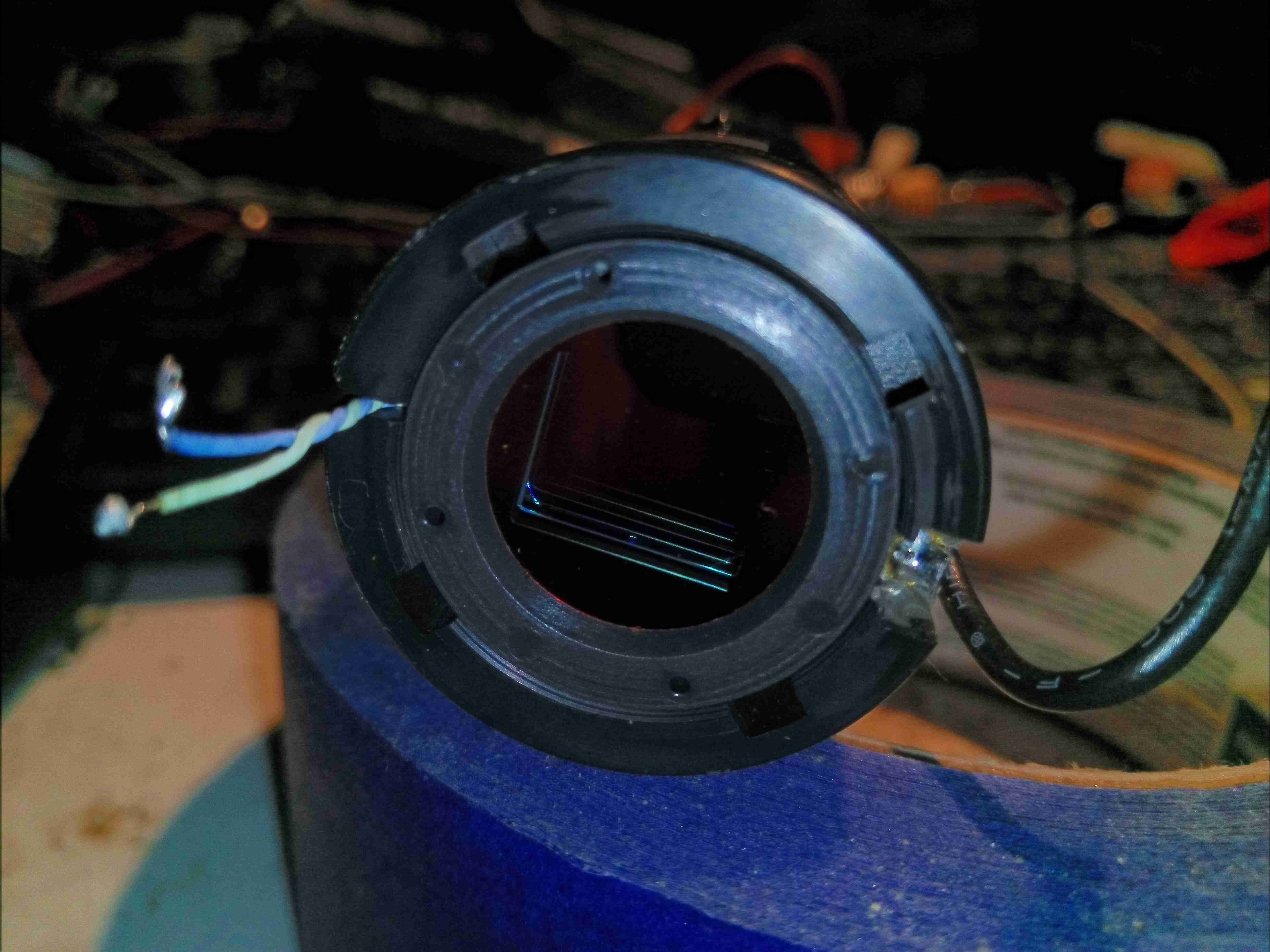
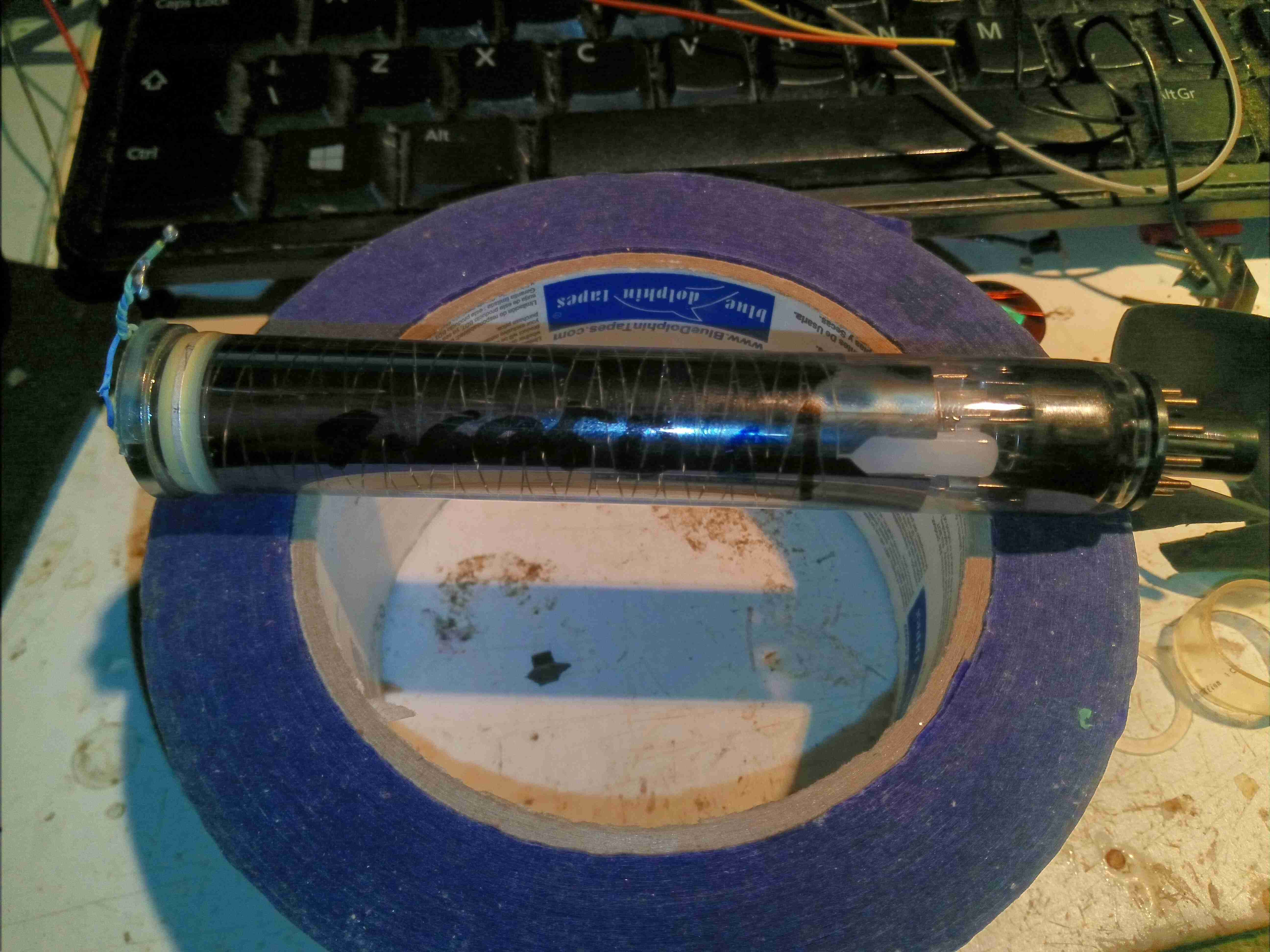
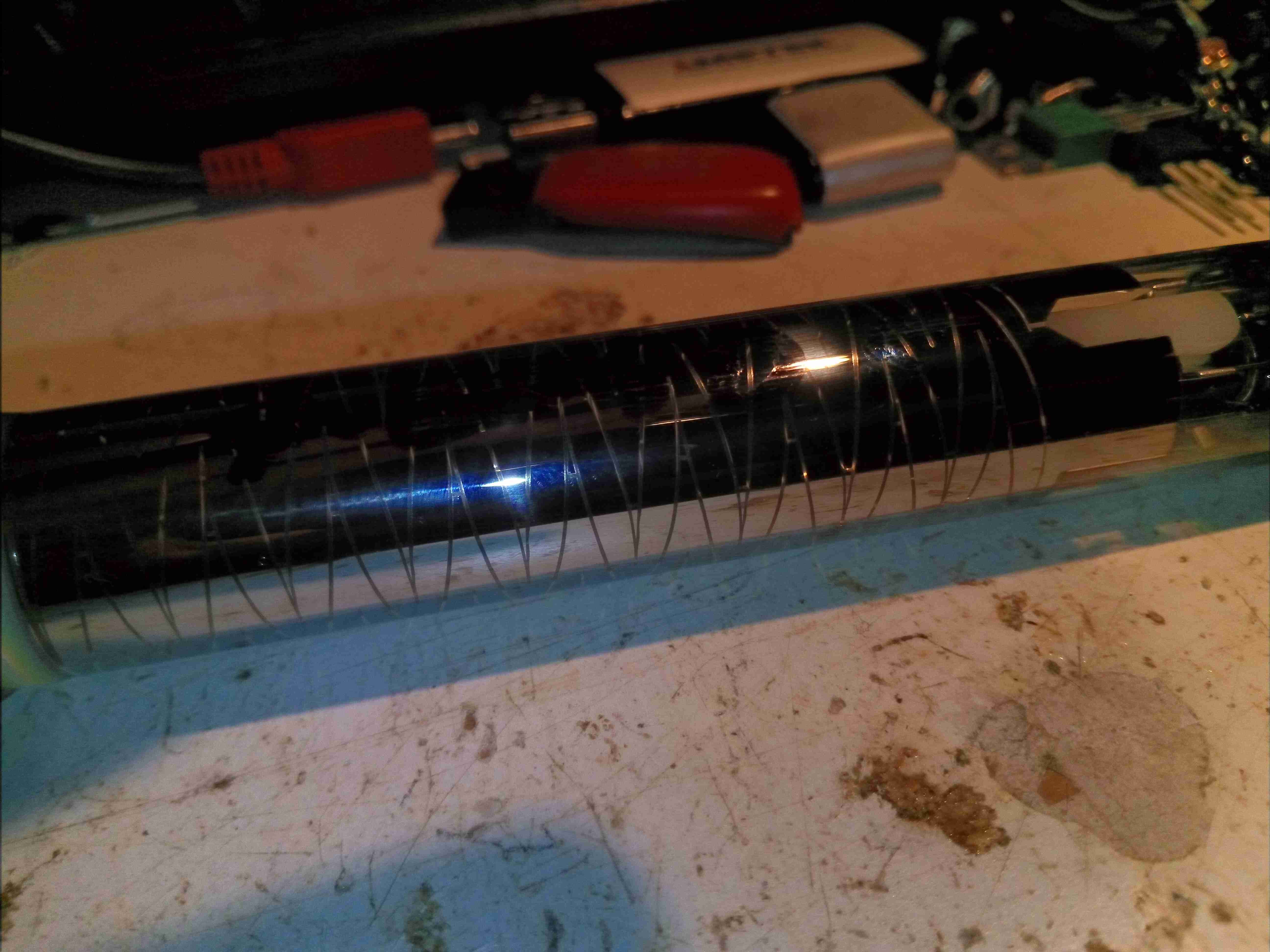
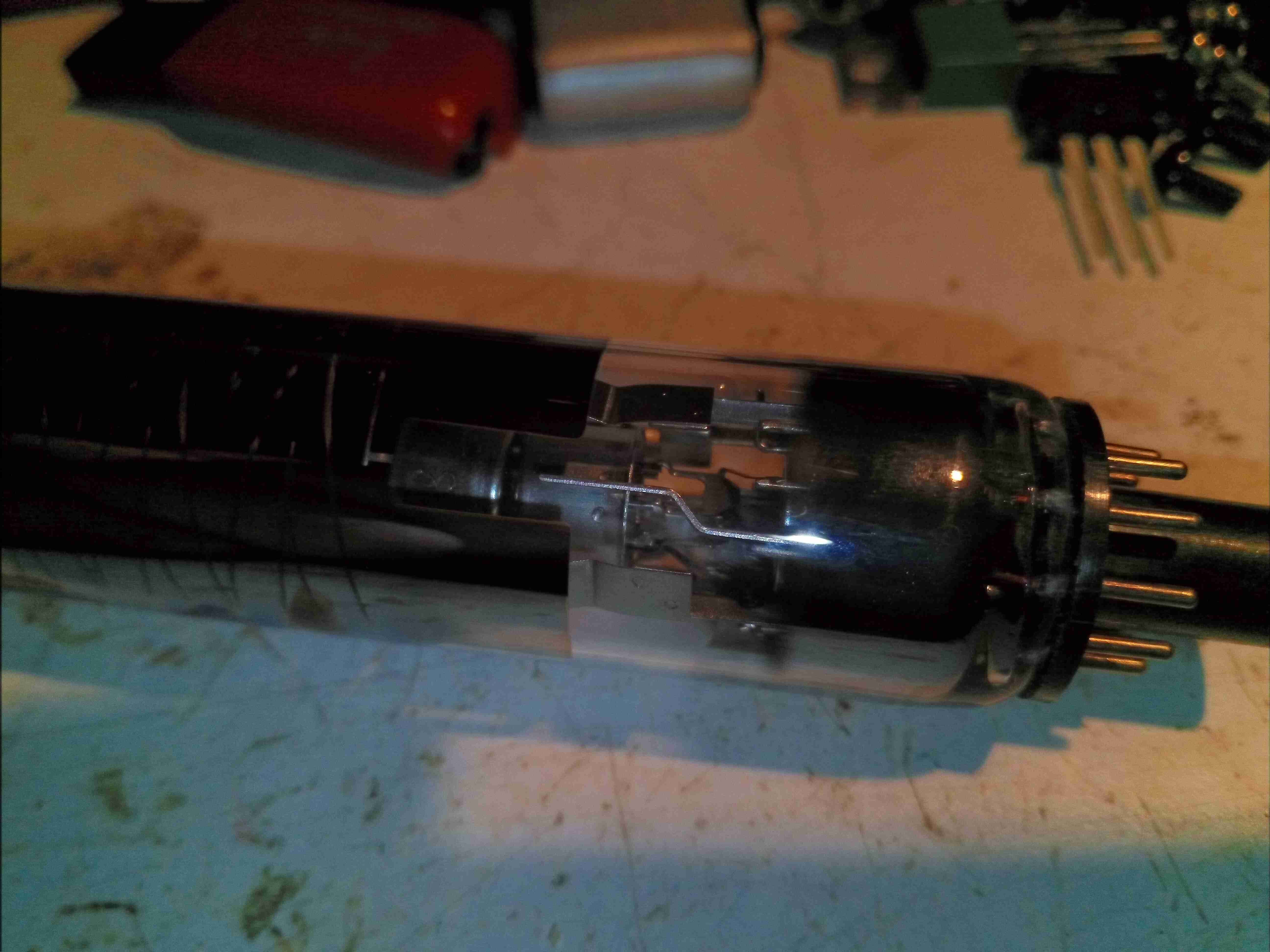
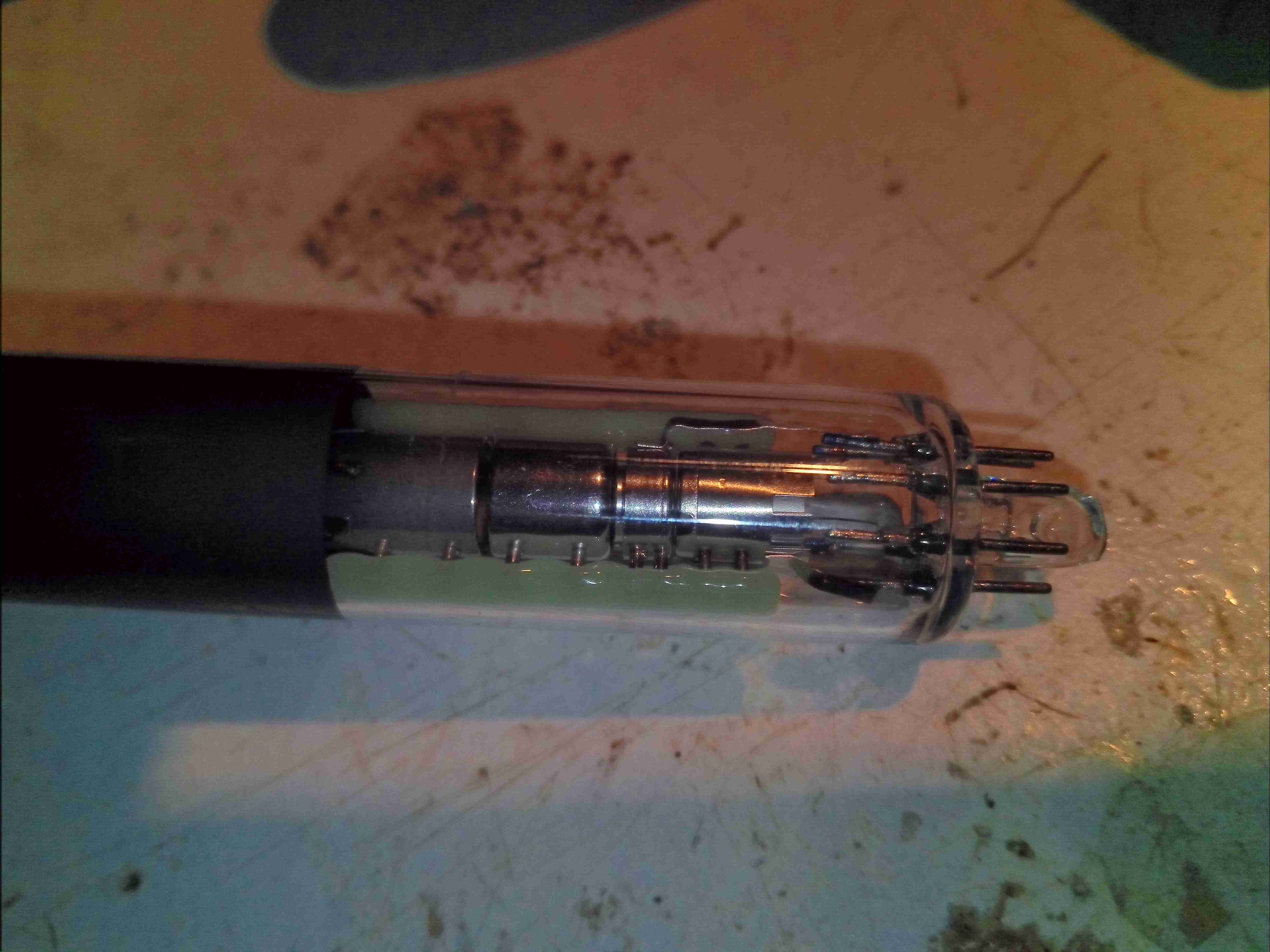
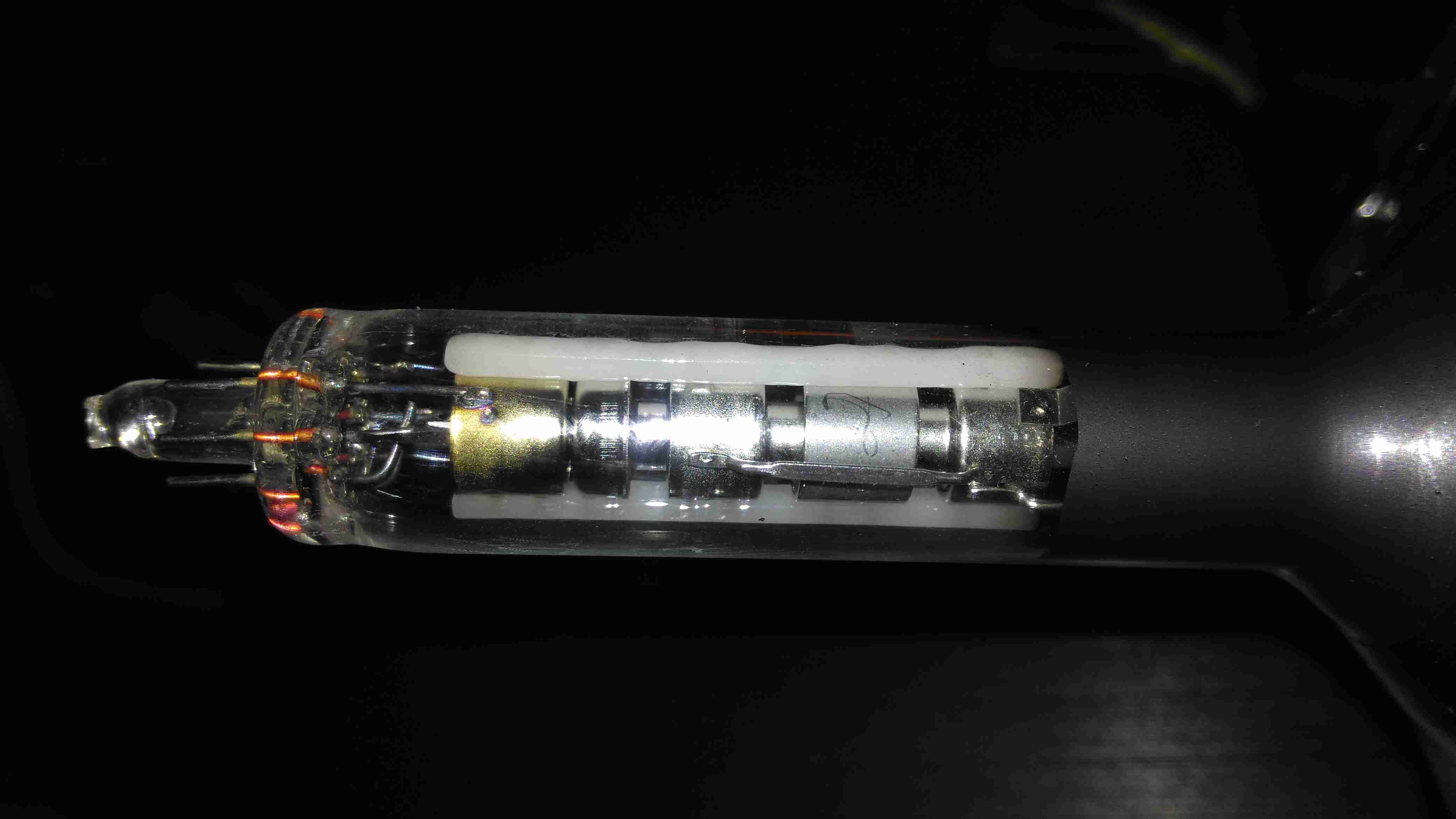
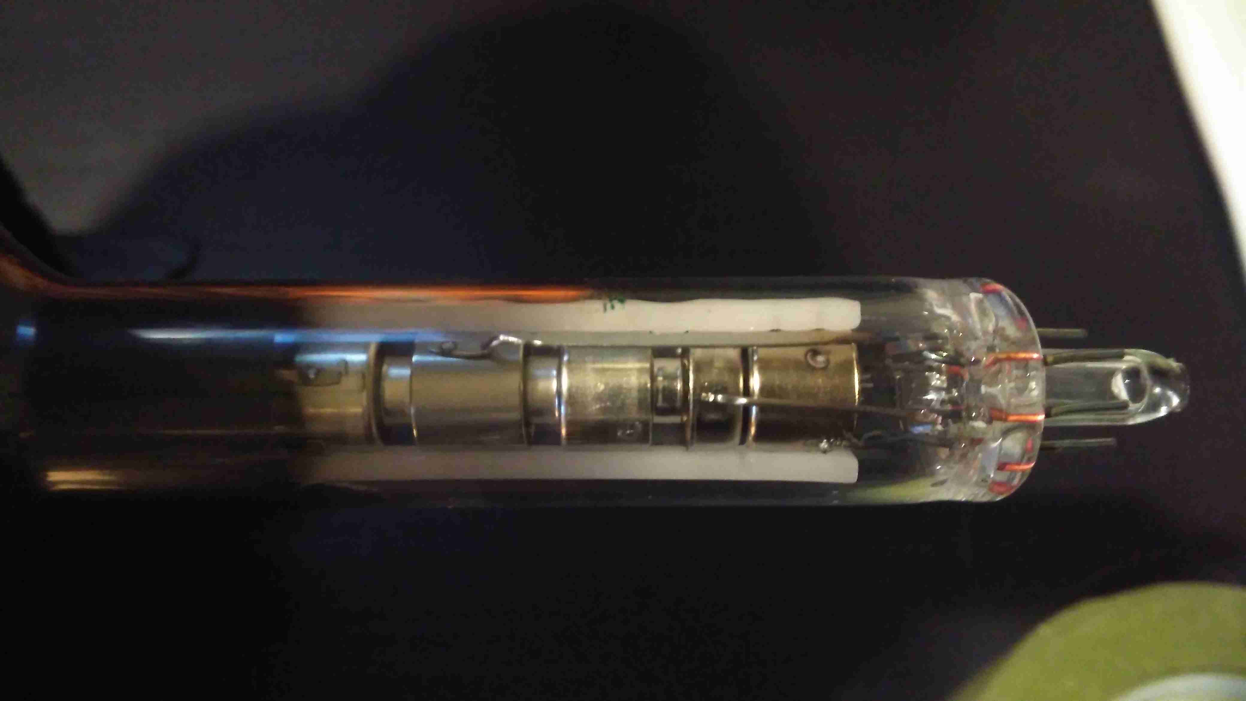
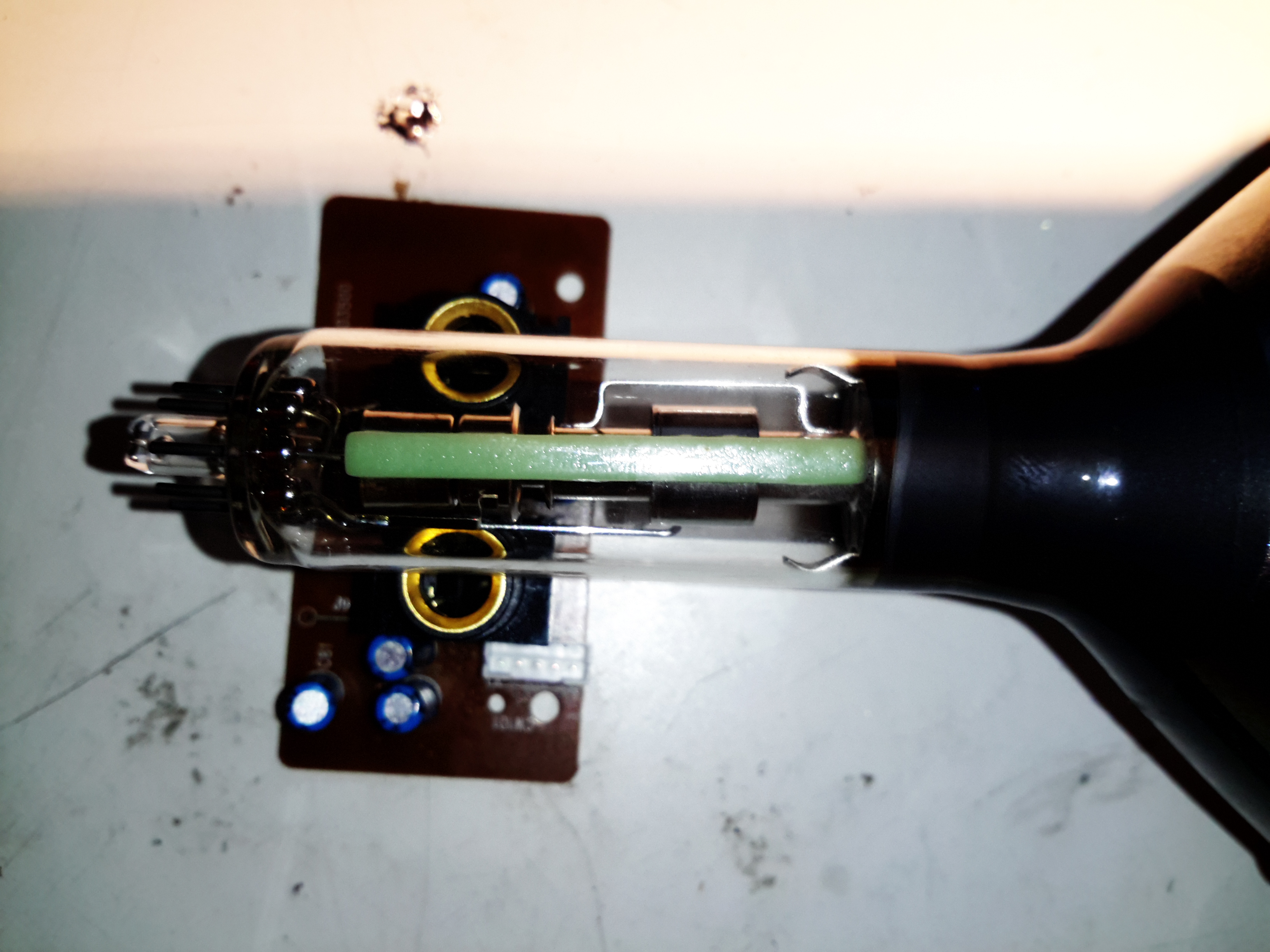
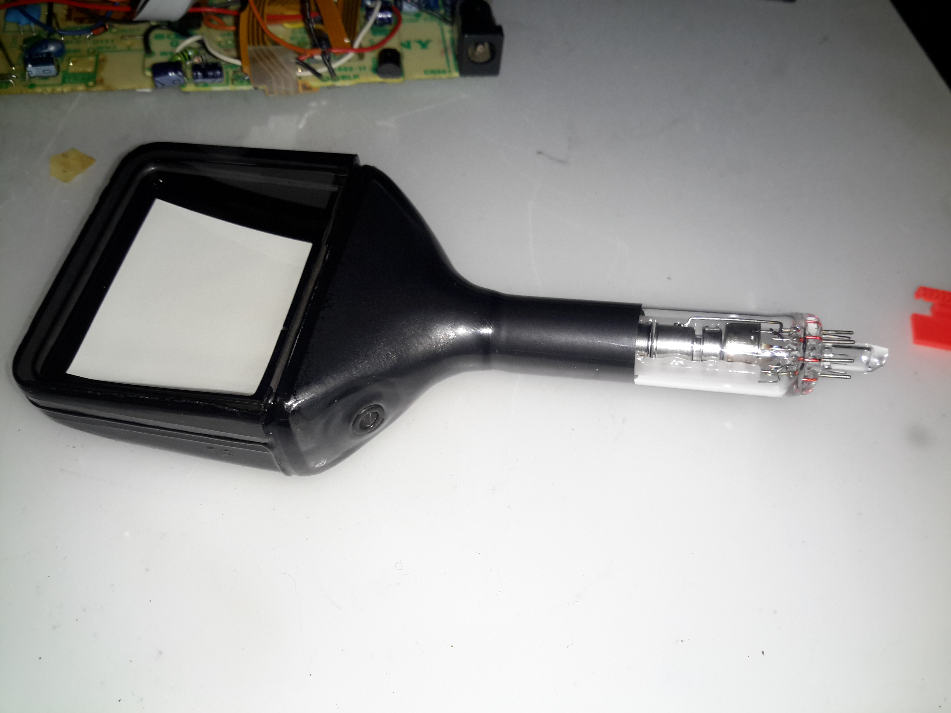
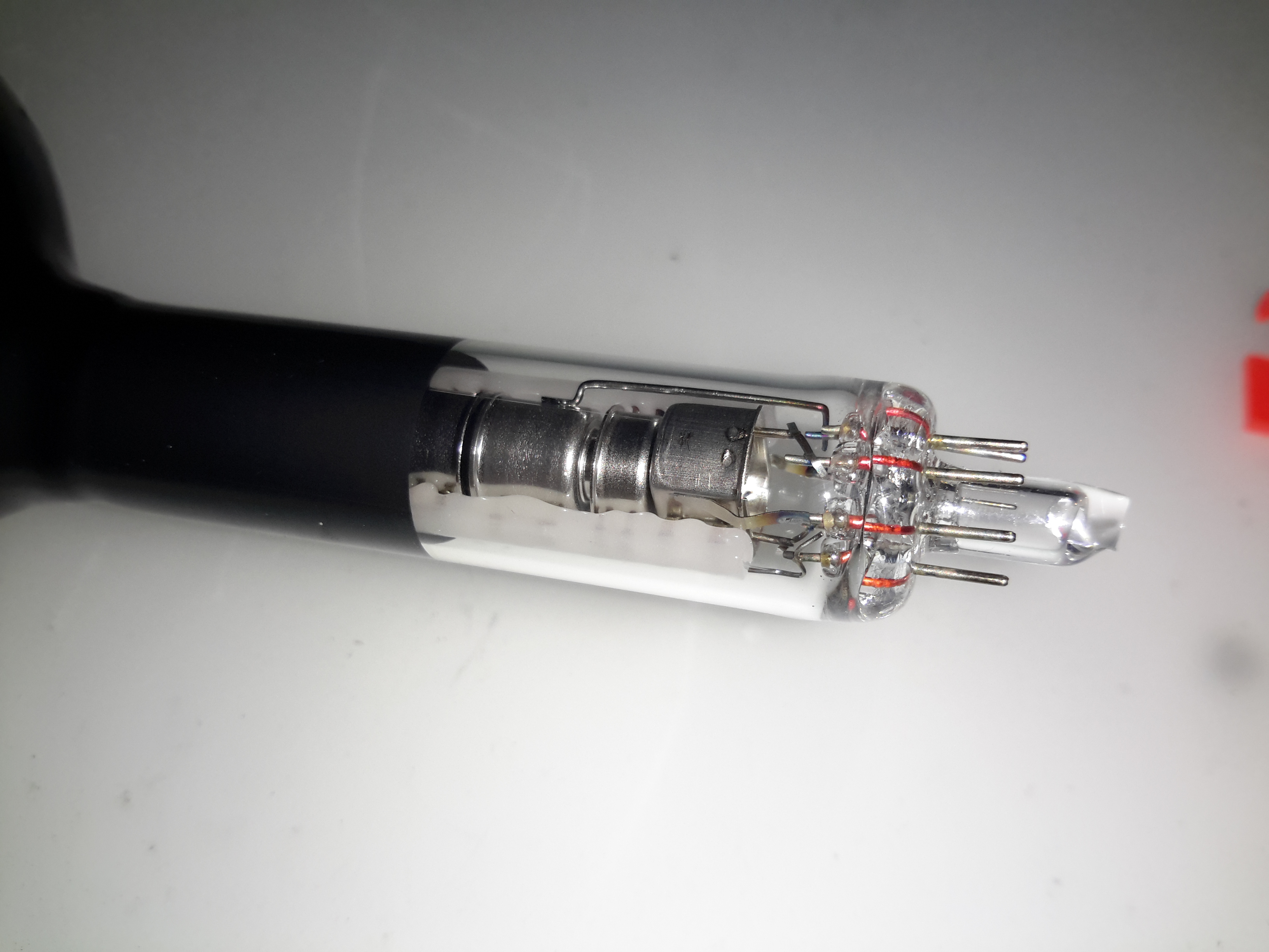
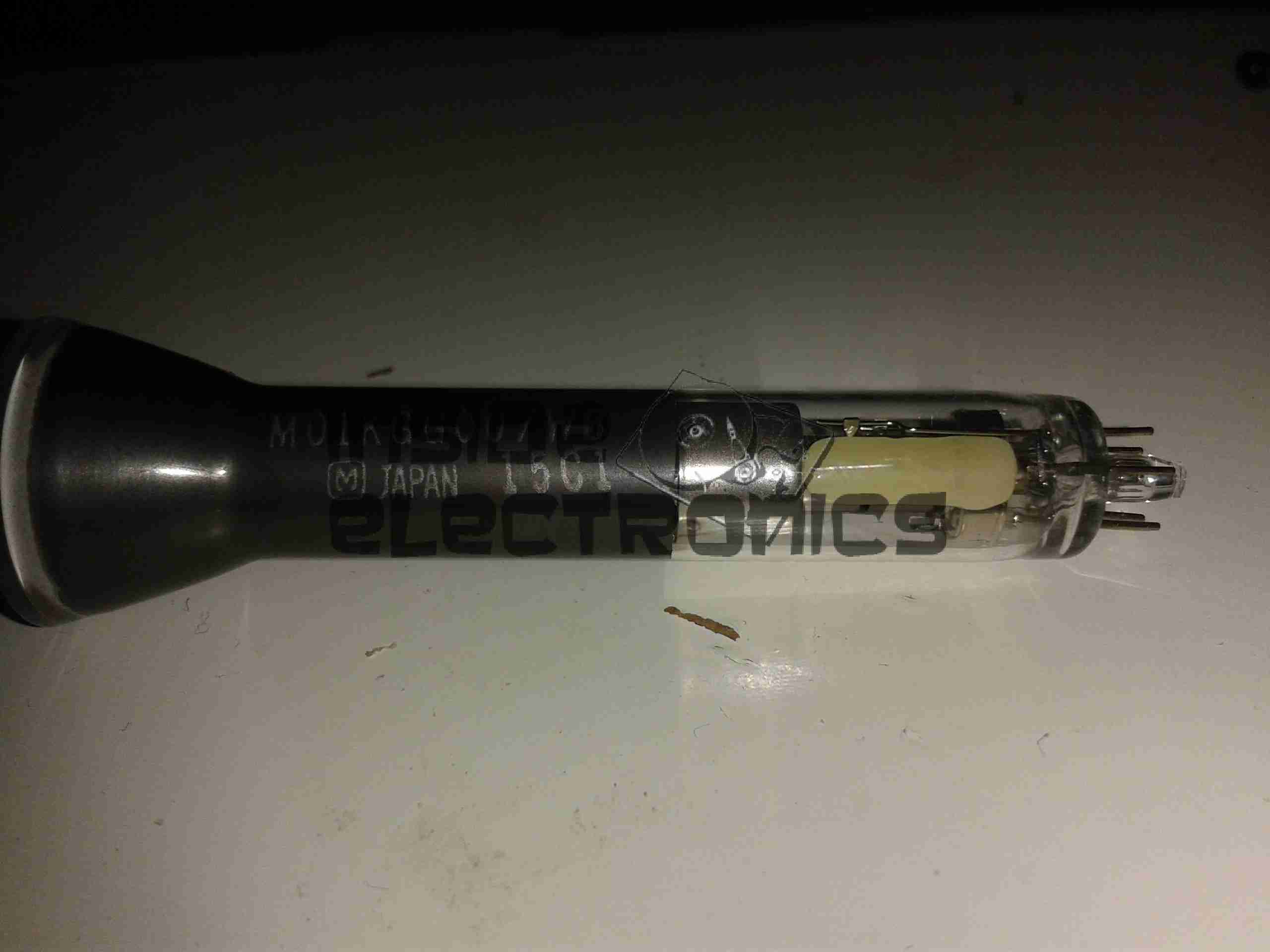
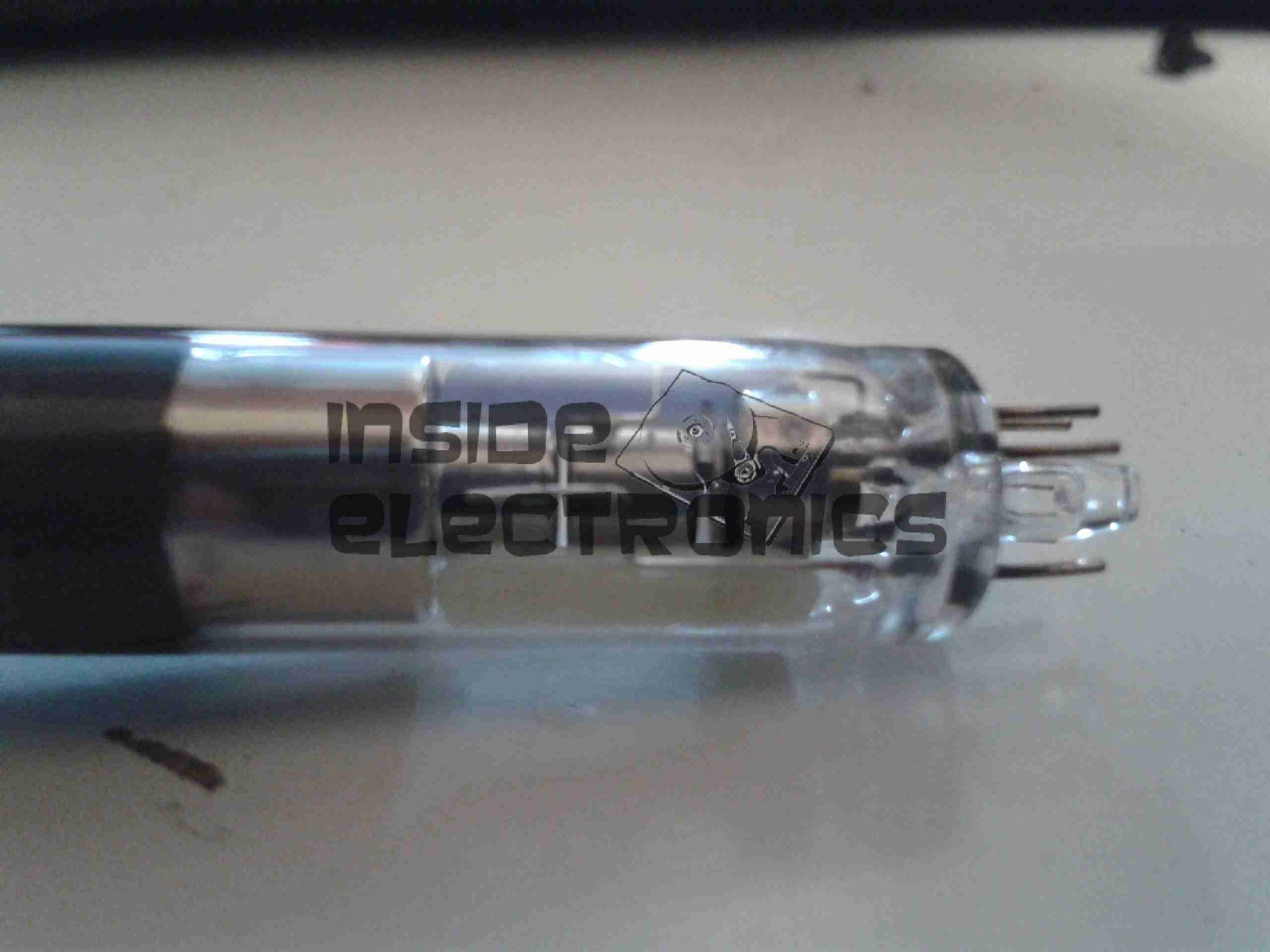
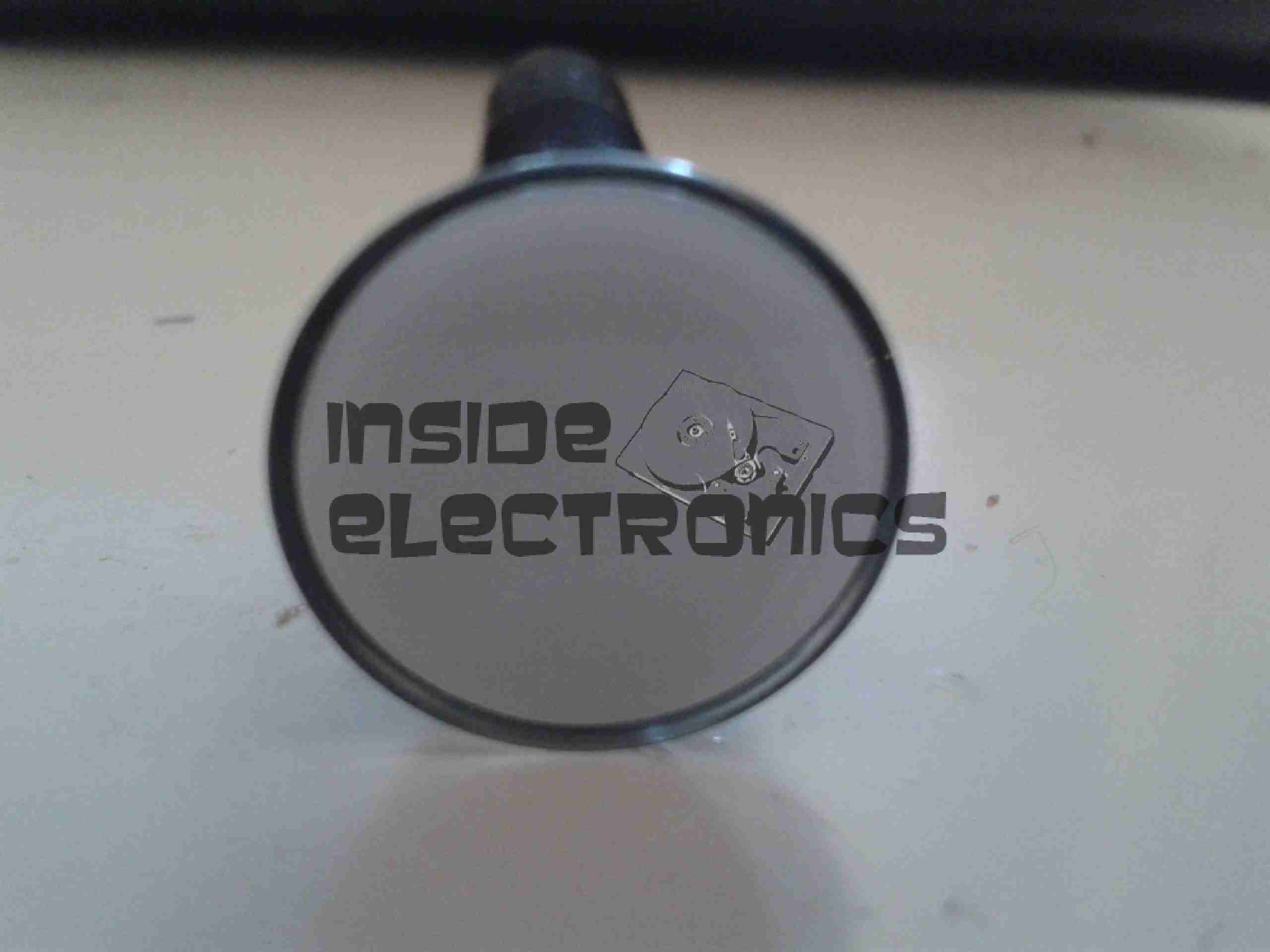
There’s not much sense in yanking the tube out of this unit, it’s identical to the Sony one’s I’ve done in the past:

Bare 40CB4 CRT
Bare 40CB4 CRT
Voltage Regulator Pass Transistor

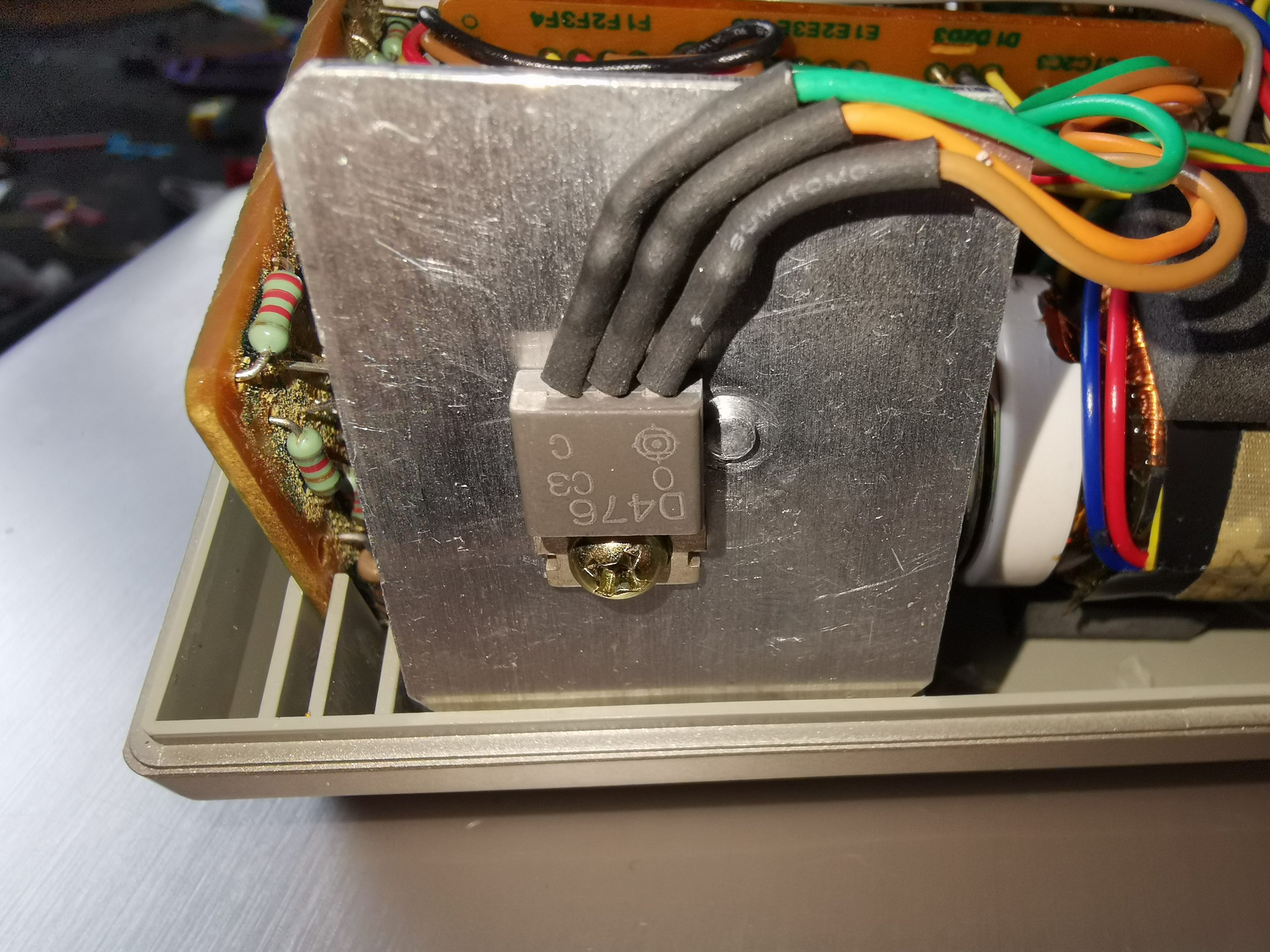
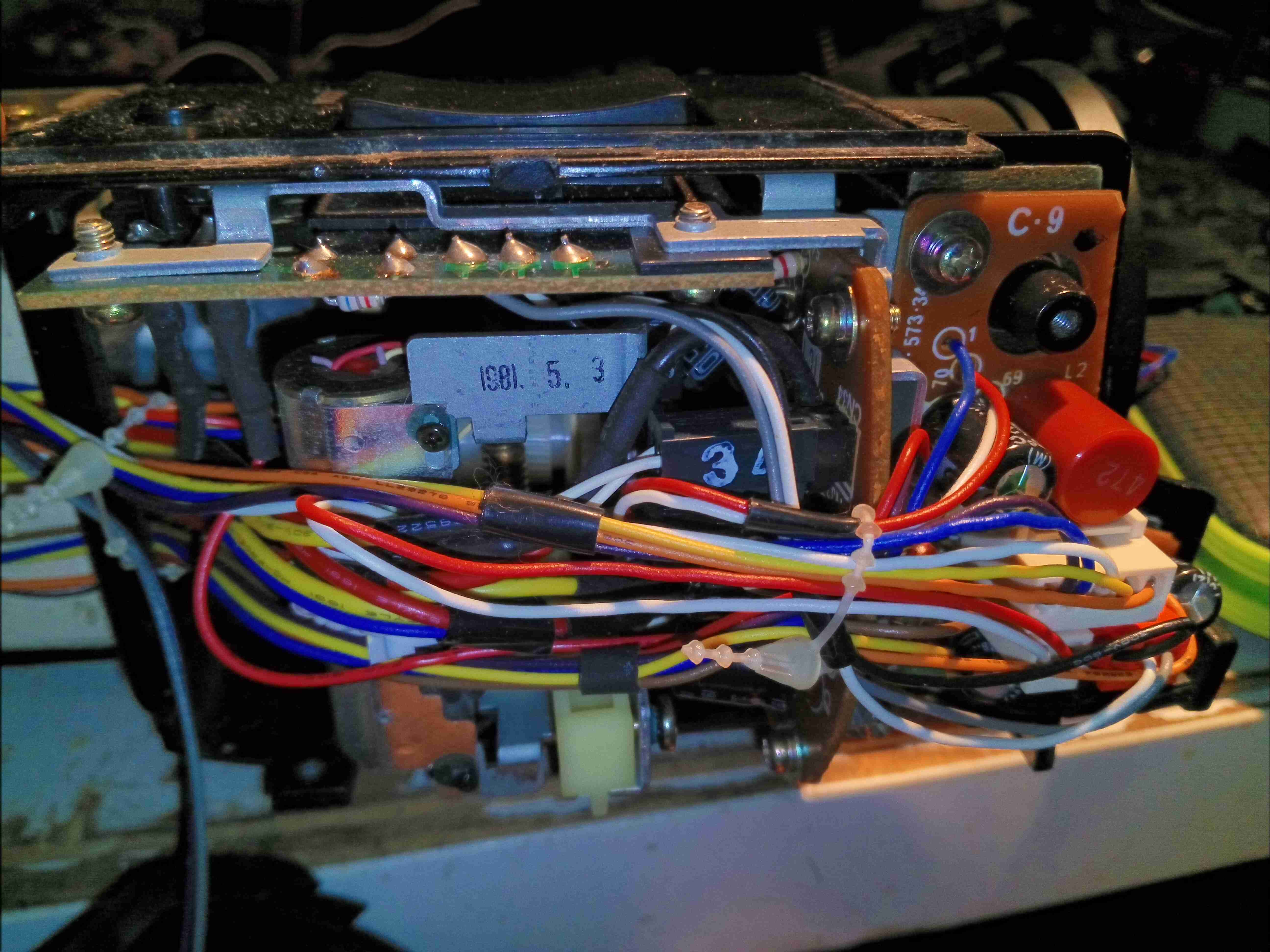
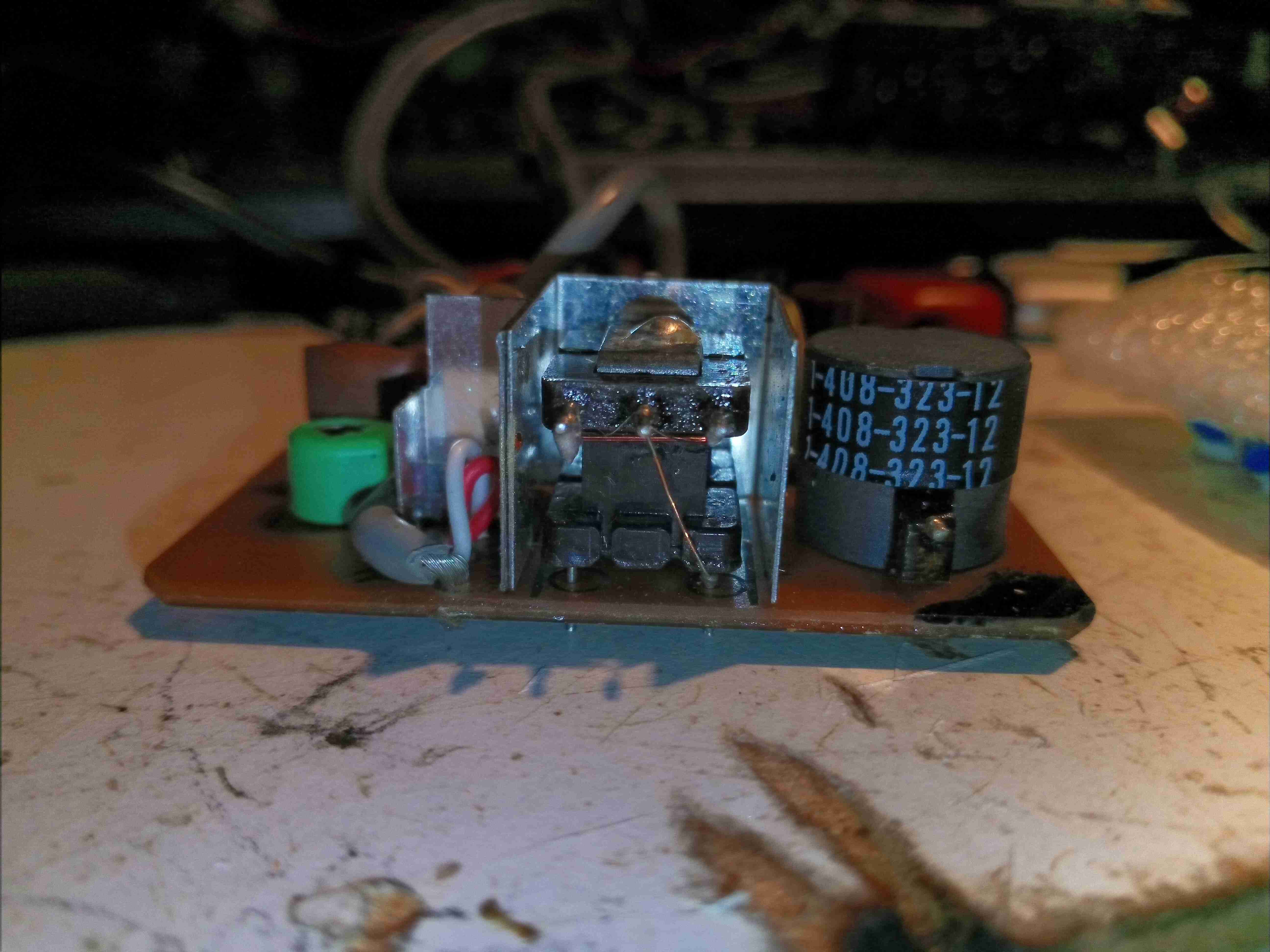
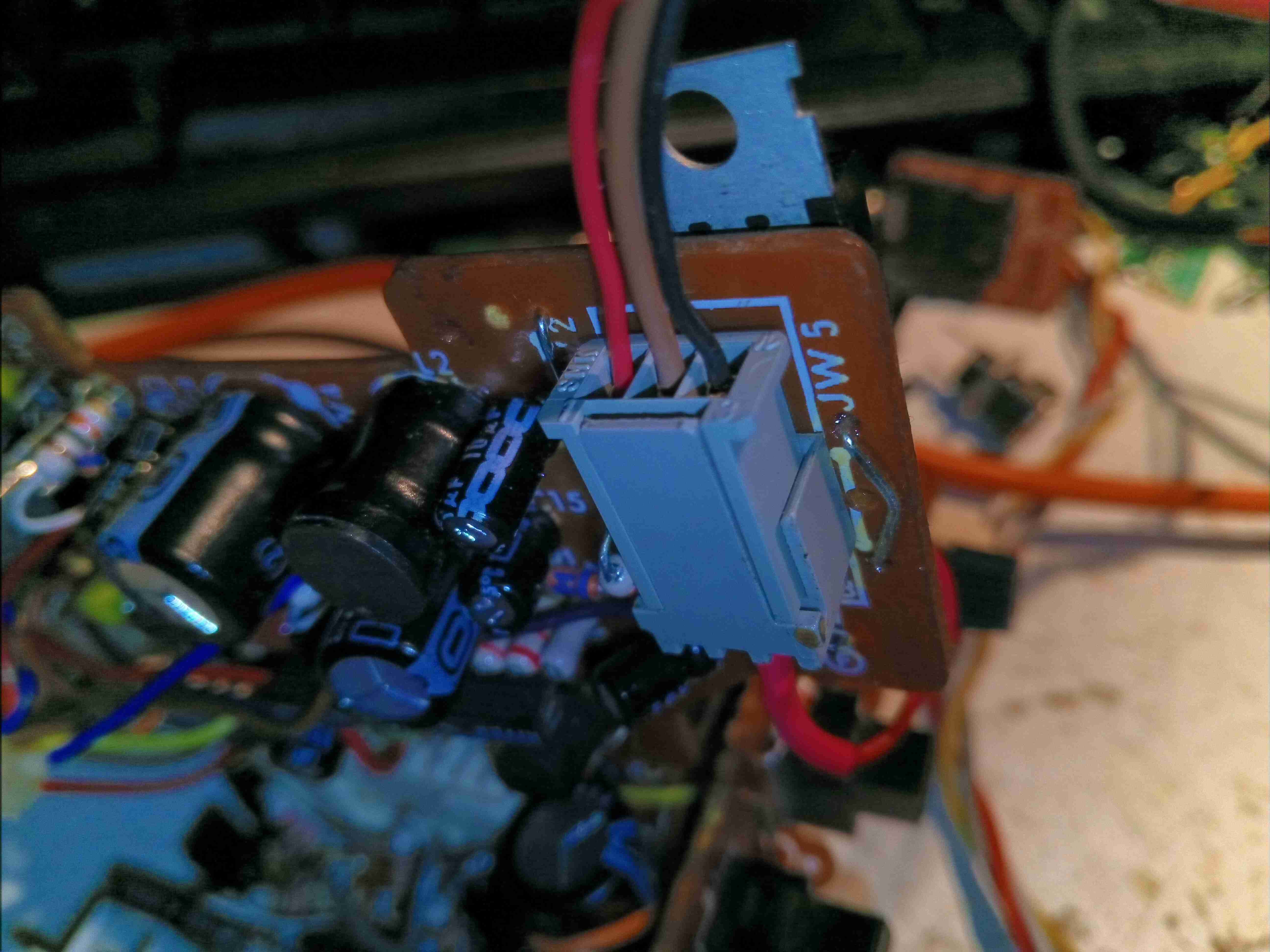
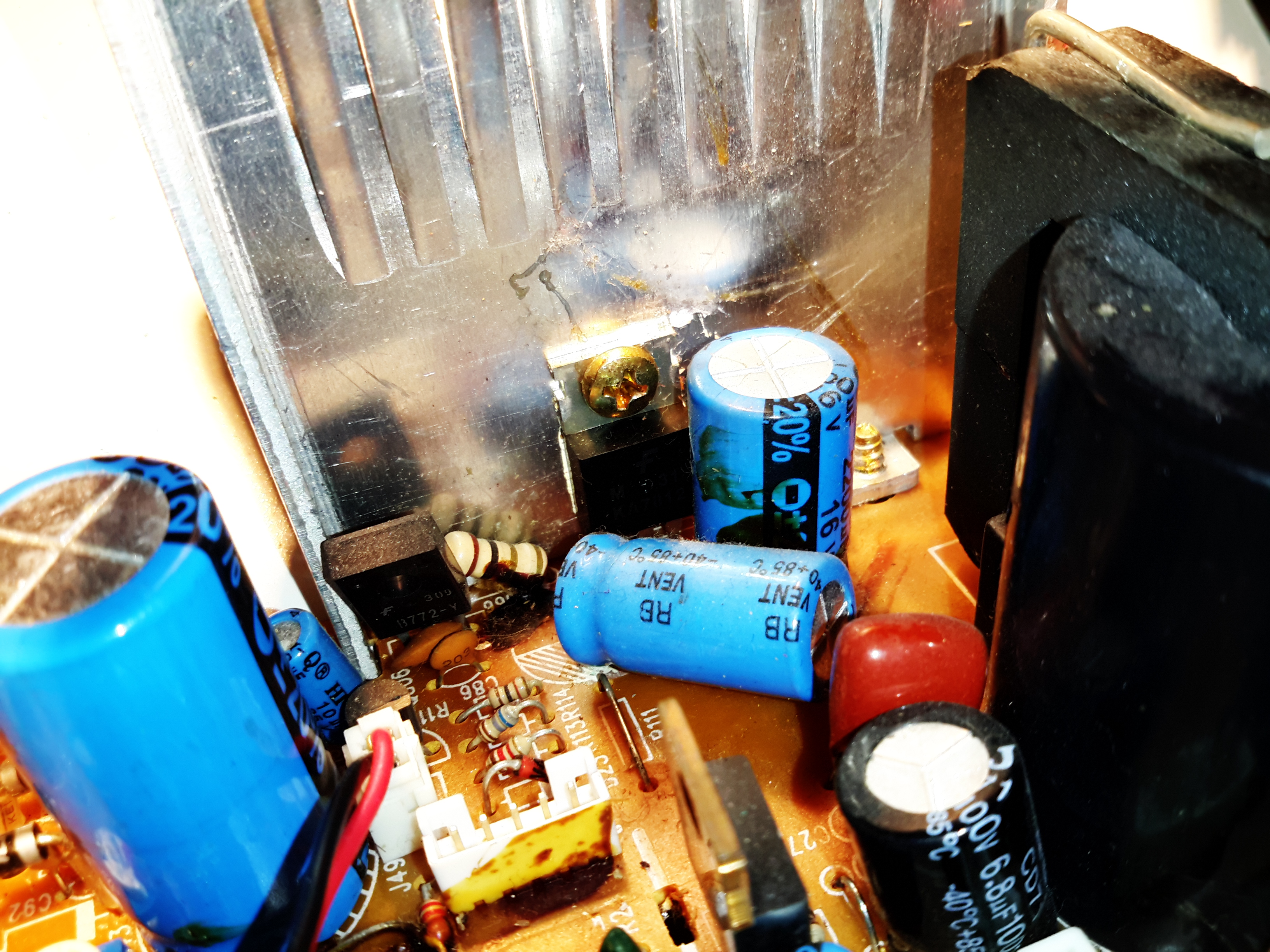
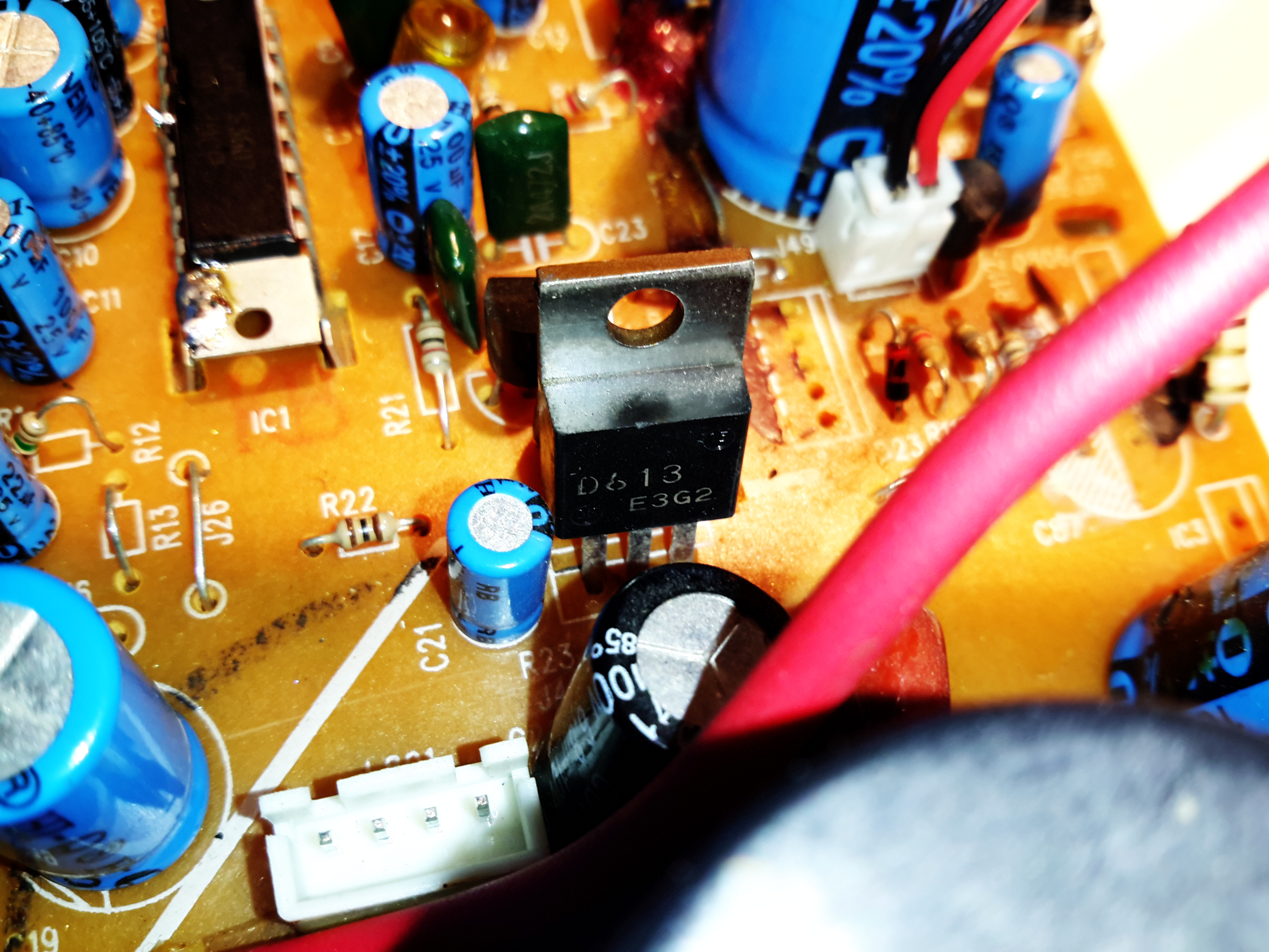
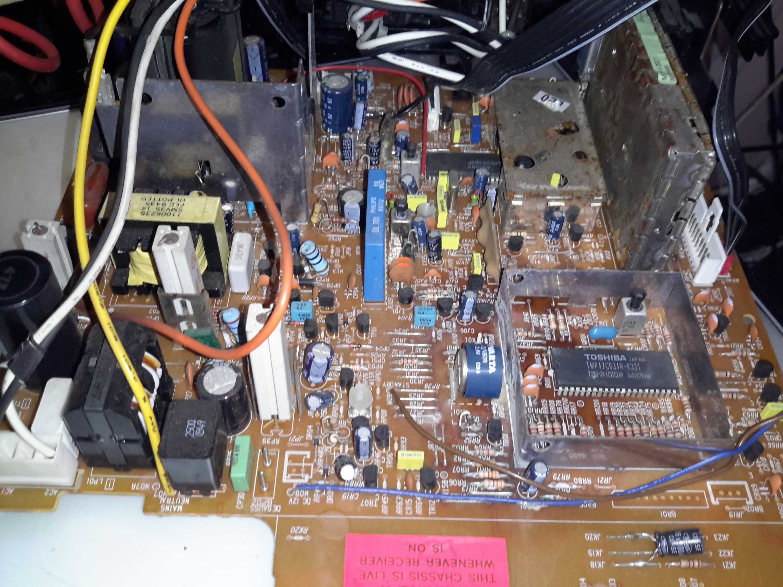
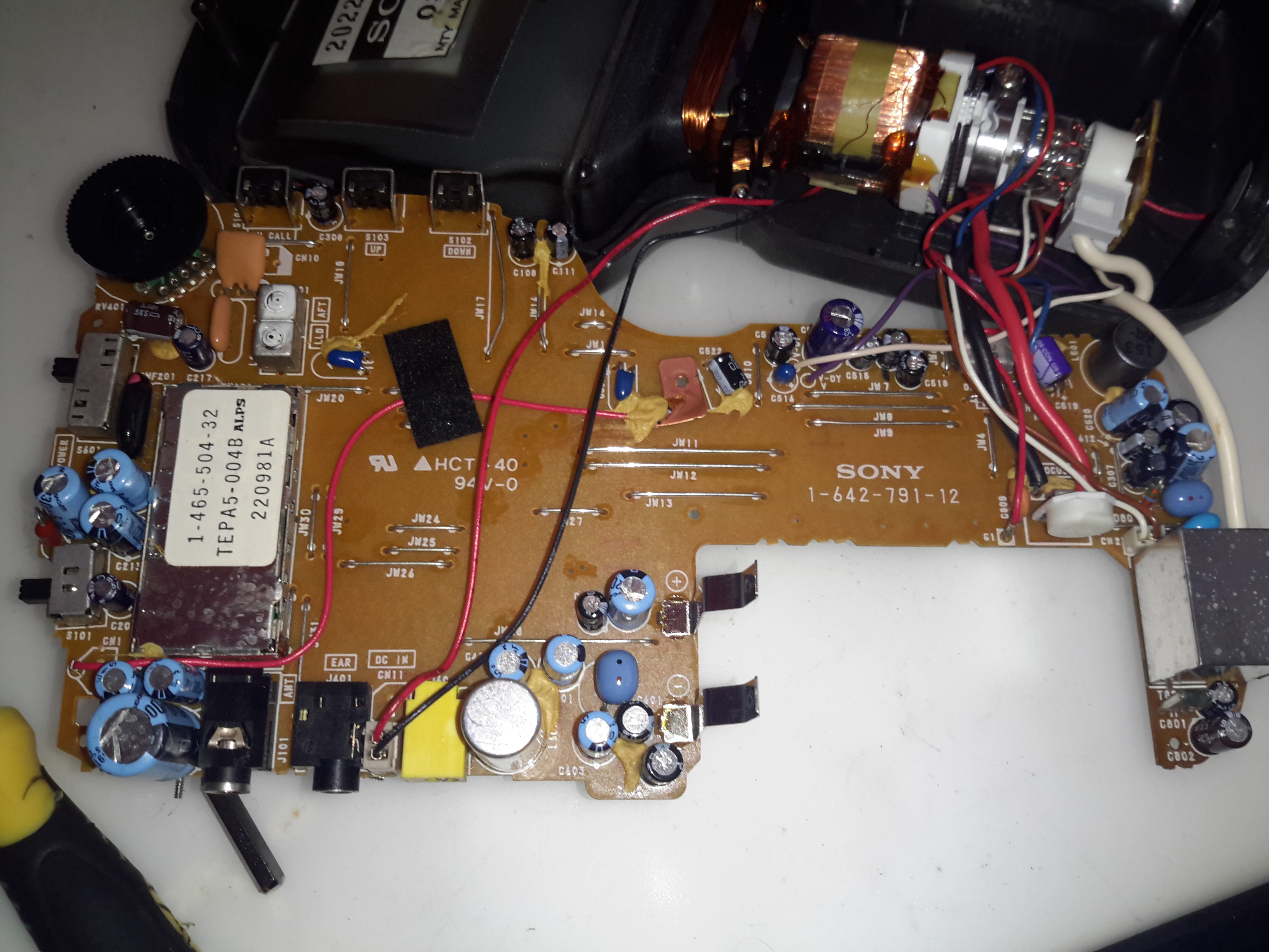
Slotted into a gap above the CRT is a large TO-220 2SD476 NPN transistor, this is part of the power circuit; it’s the series pass element regulating the input 12v down to 9v for all the remaining circuits. The aluminium sheet on the back provides some heatsinking as this part gets warm! Current draw of this unit with no video input is about 260mA.

CRT Removed & Vertical Board

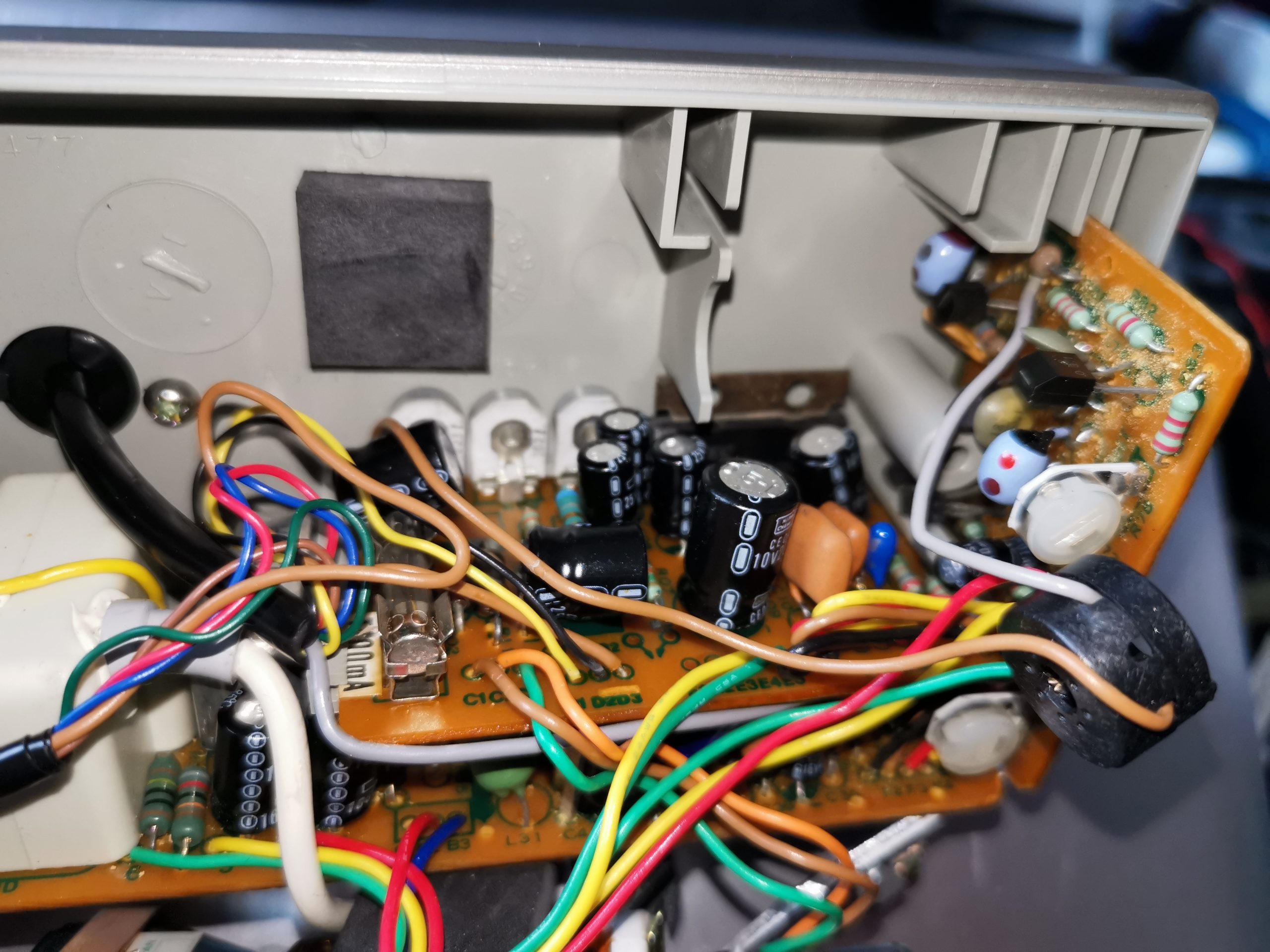
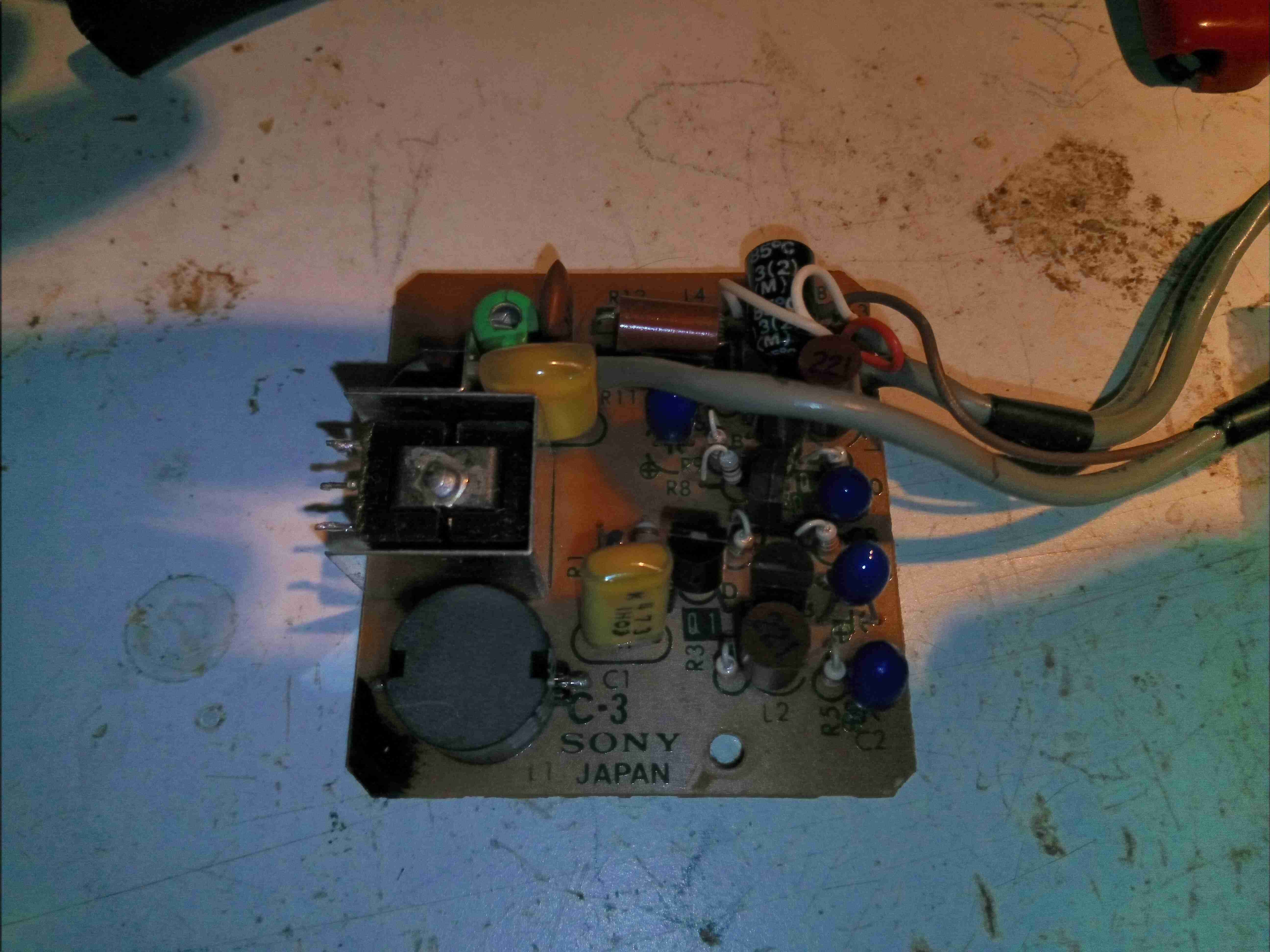
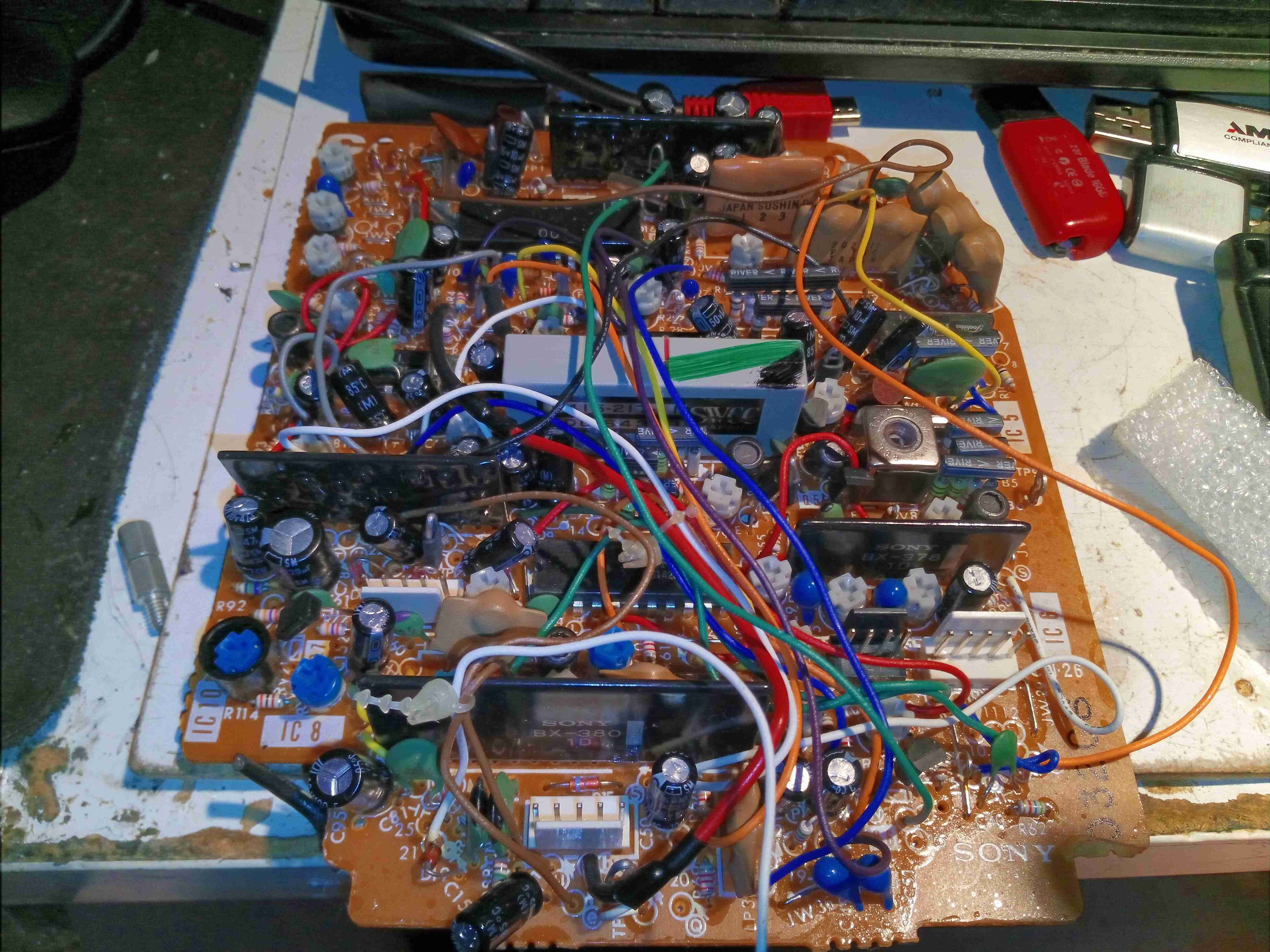
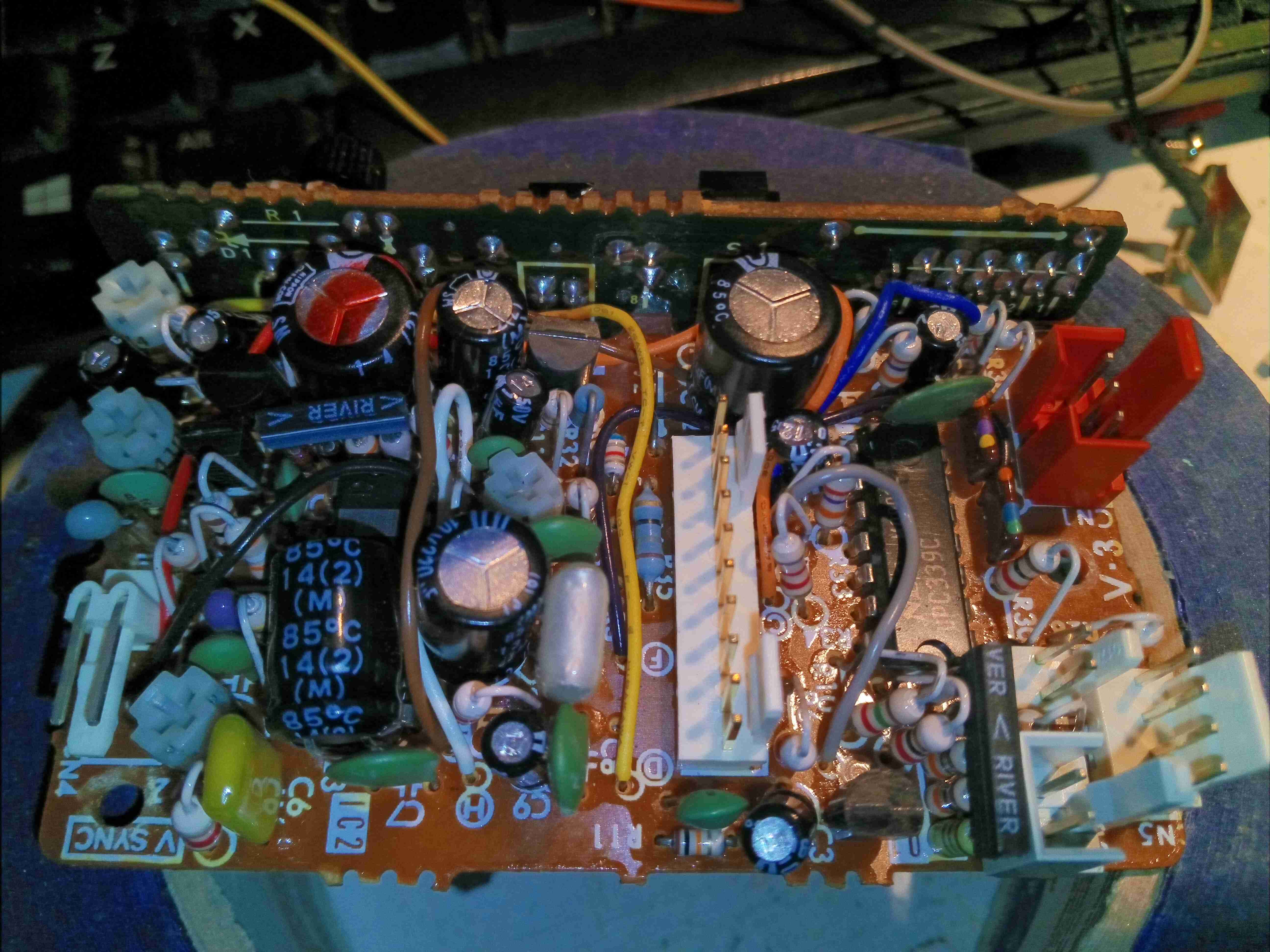
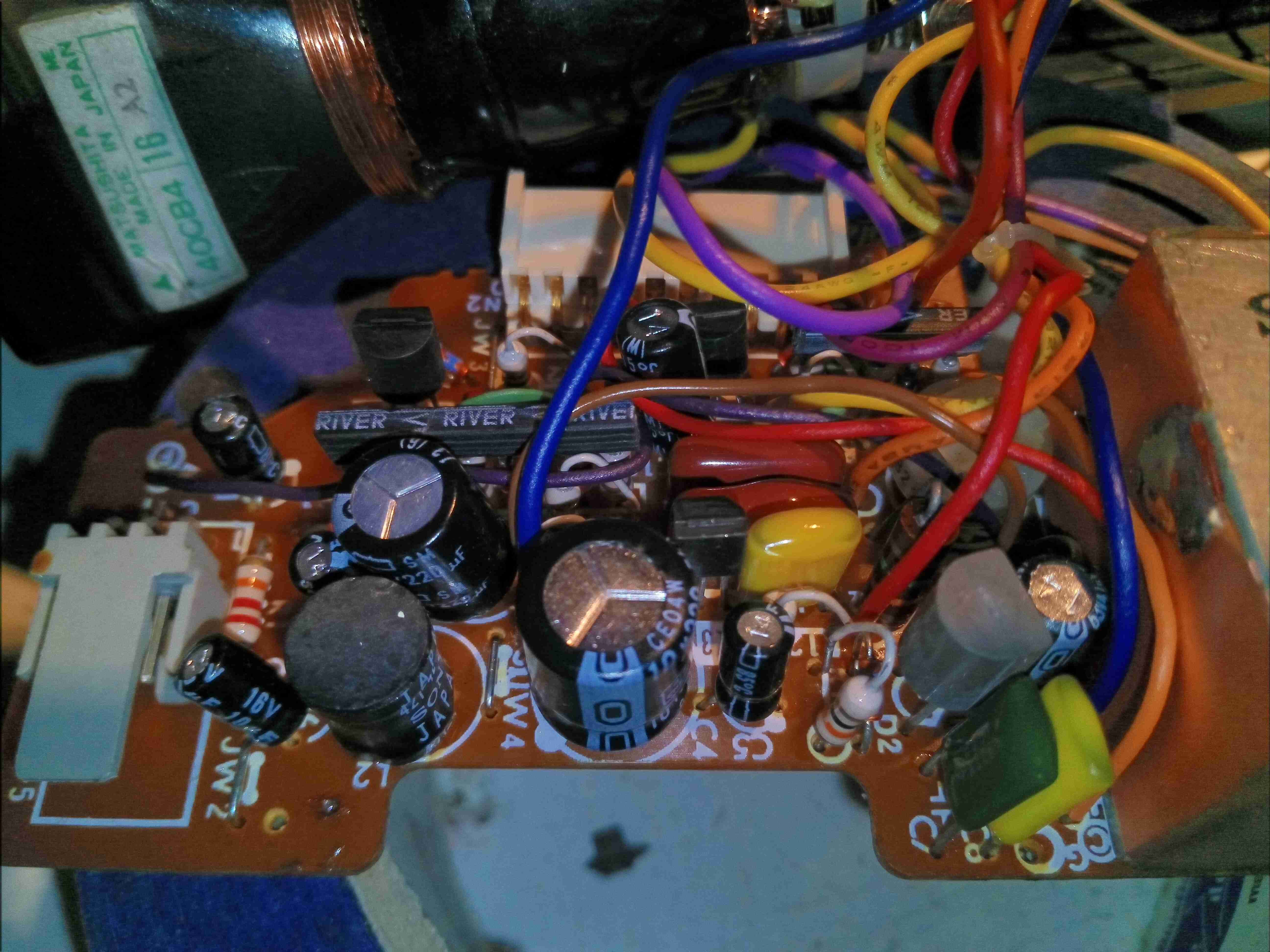
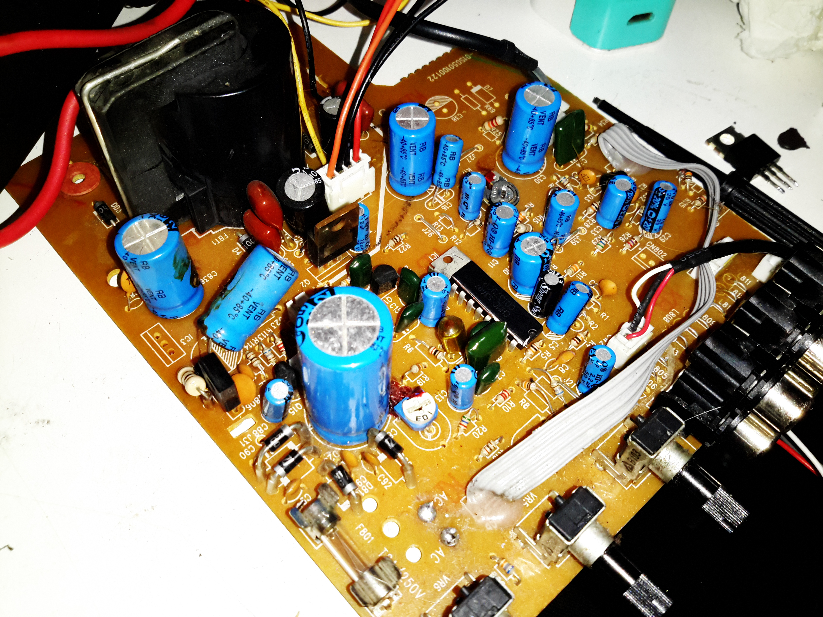
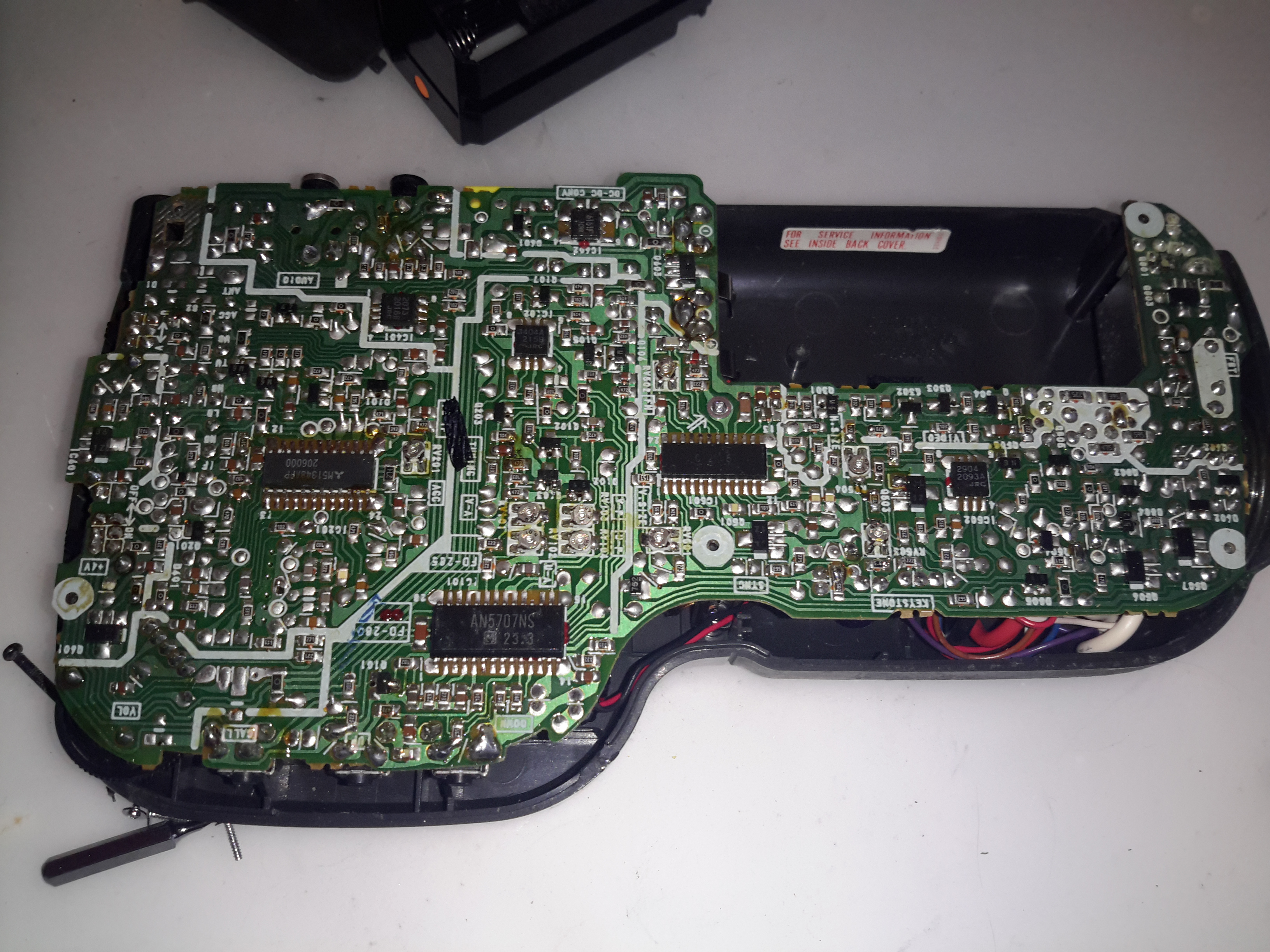
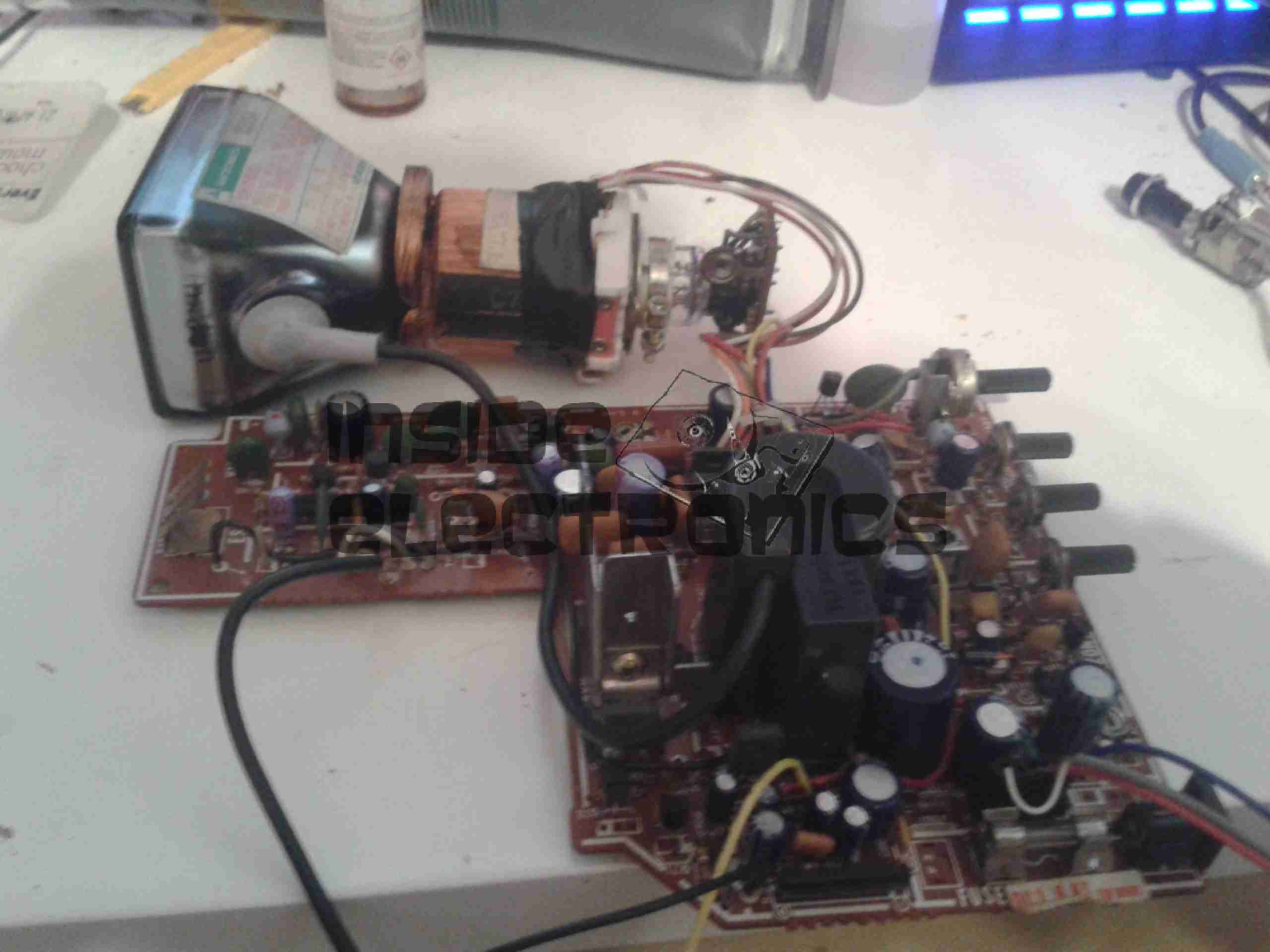
Popping the CRT out allows a view of the Vertical & Power Board. This hosts the input linear voltage regulator, and the vertical output control circuitry. Hiding at the back on the right is a NEC µPC1031H2 Vertical Deflection Controller.

Horizontal & Video Boards

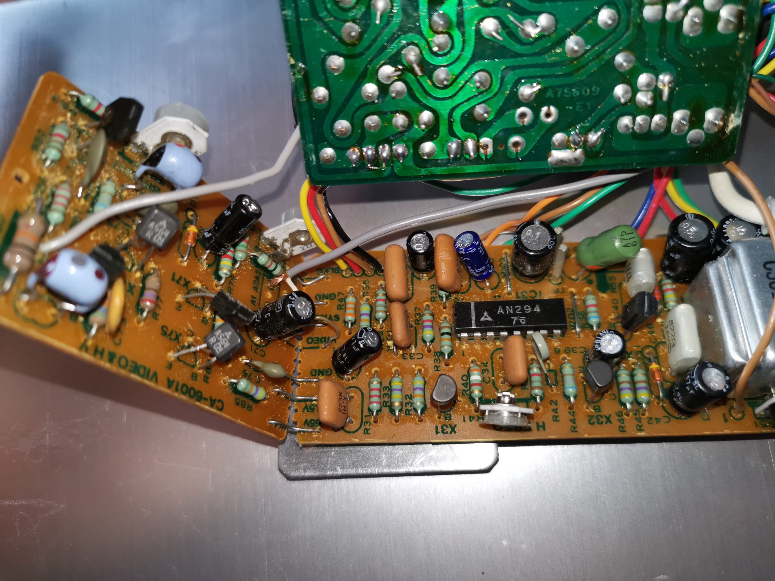
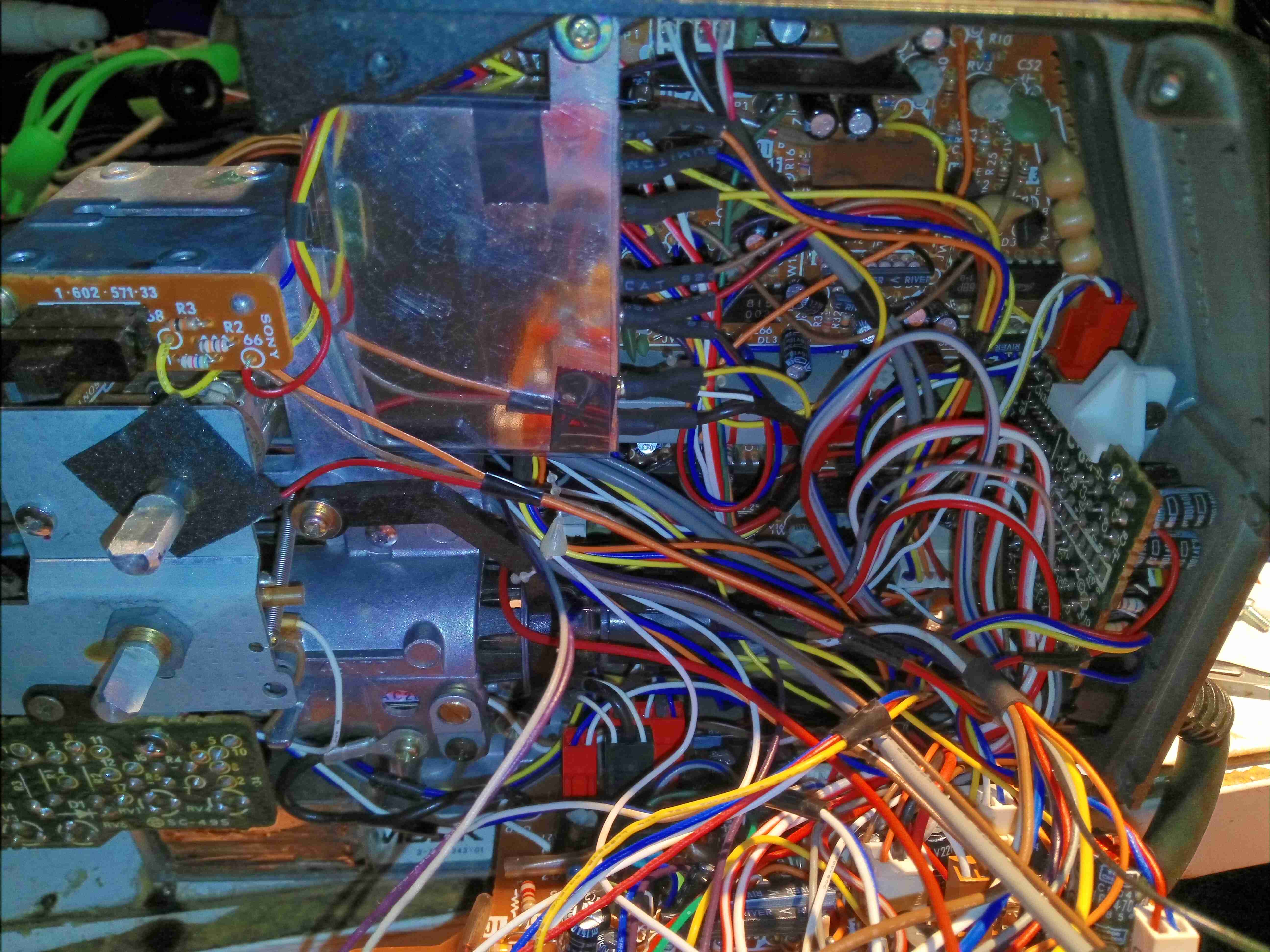
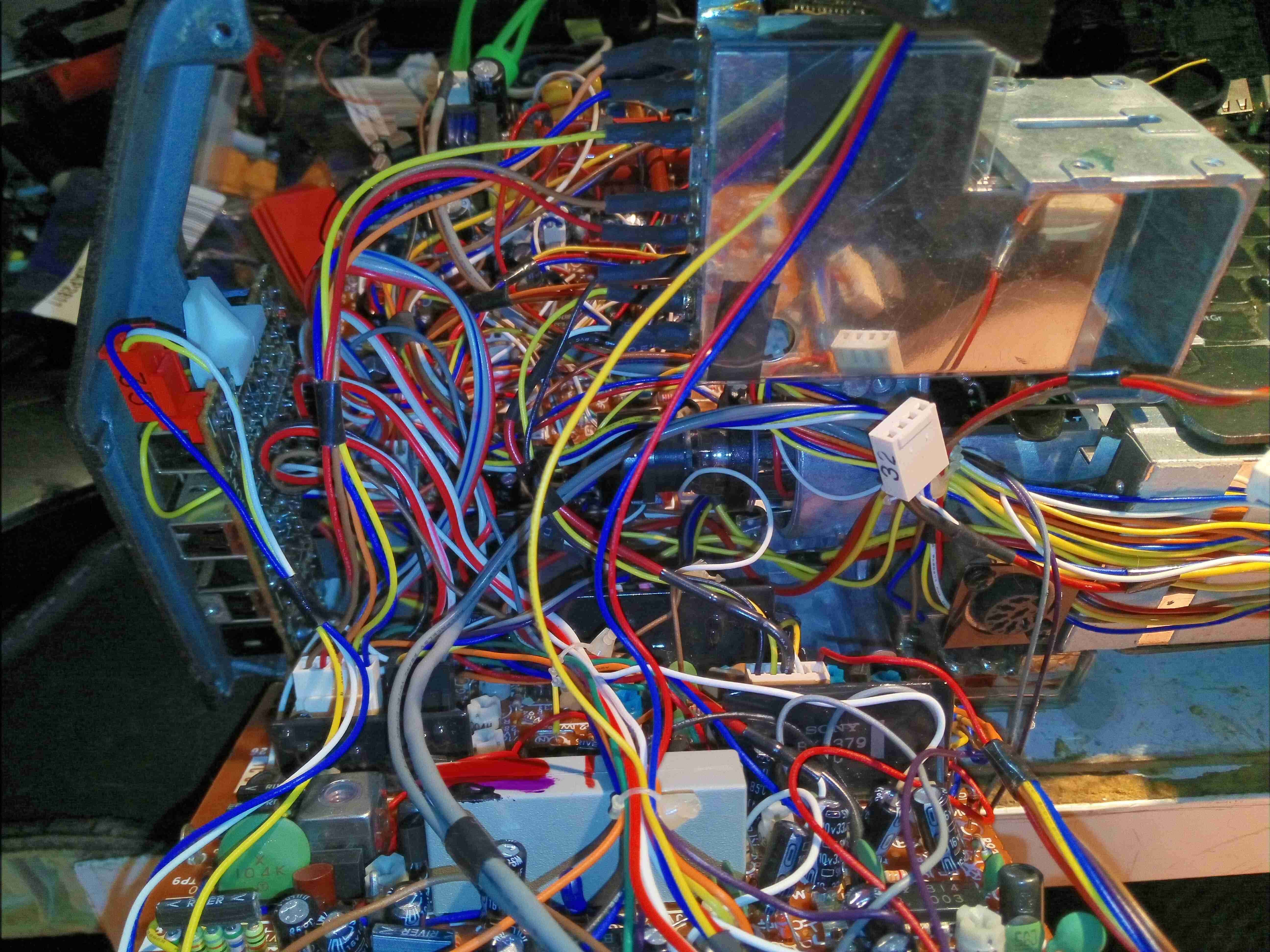
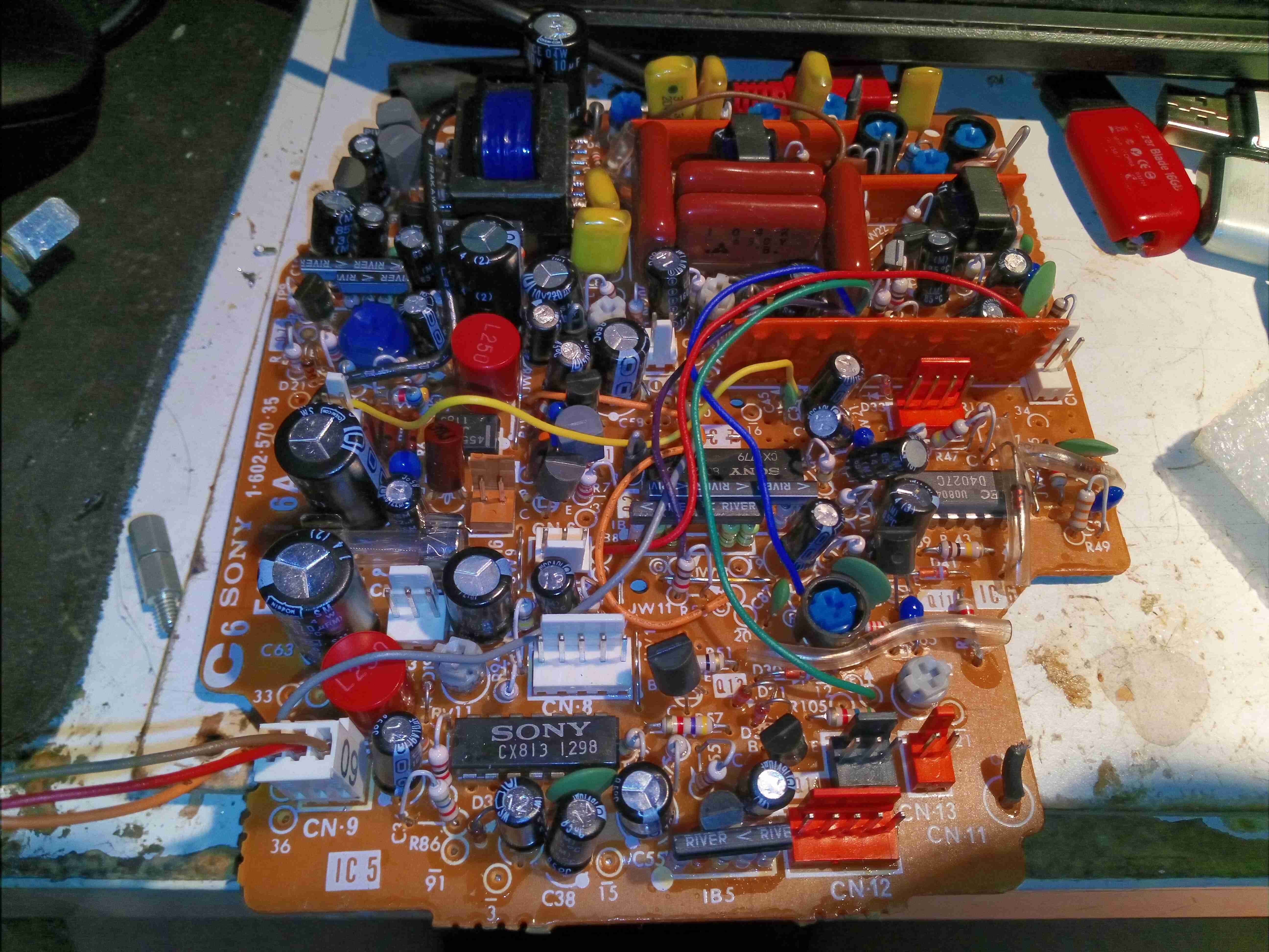
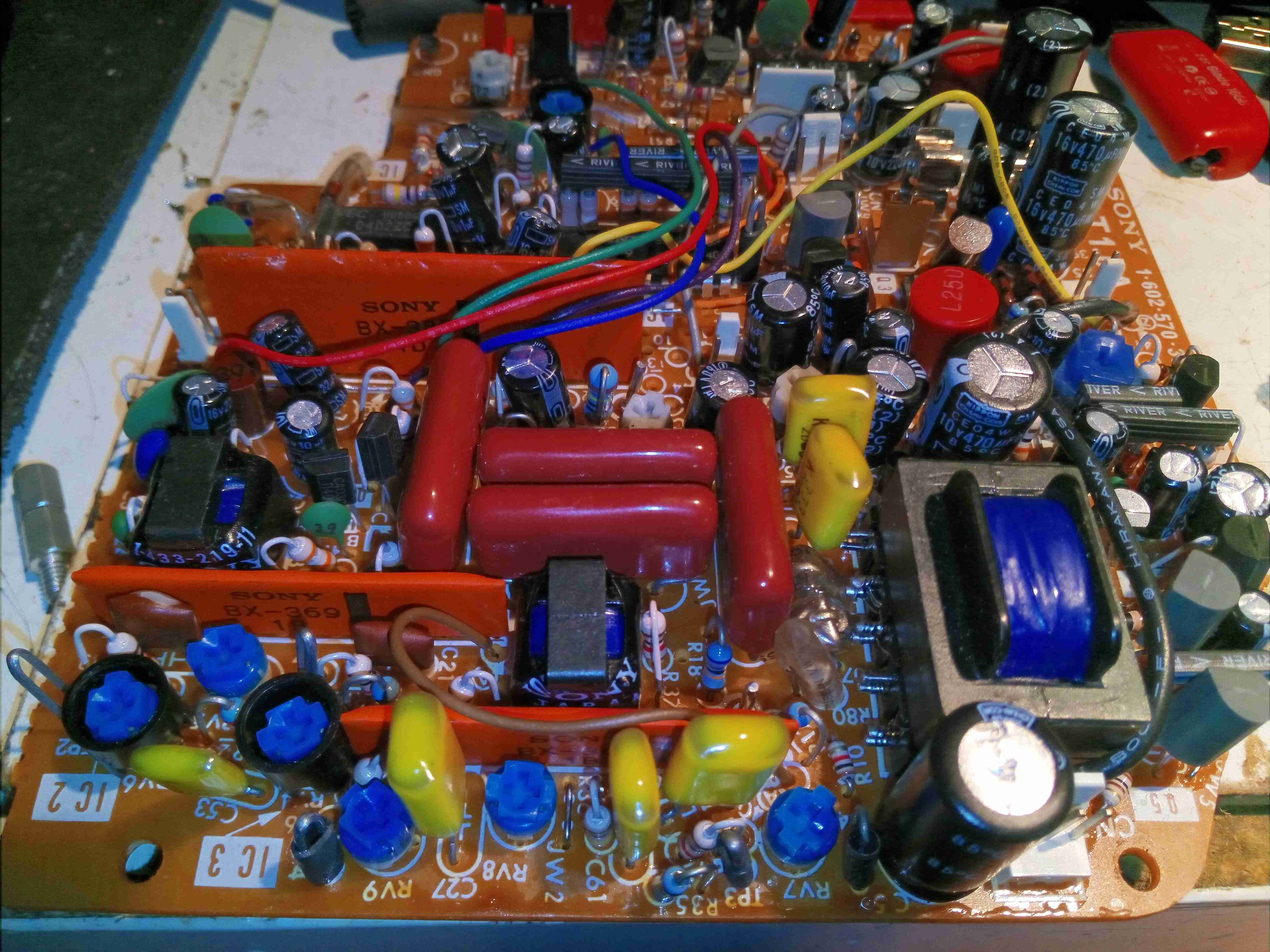
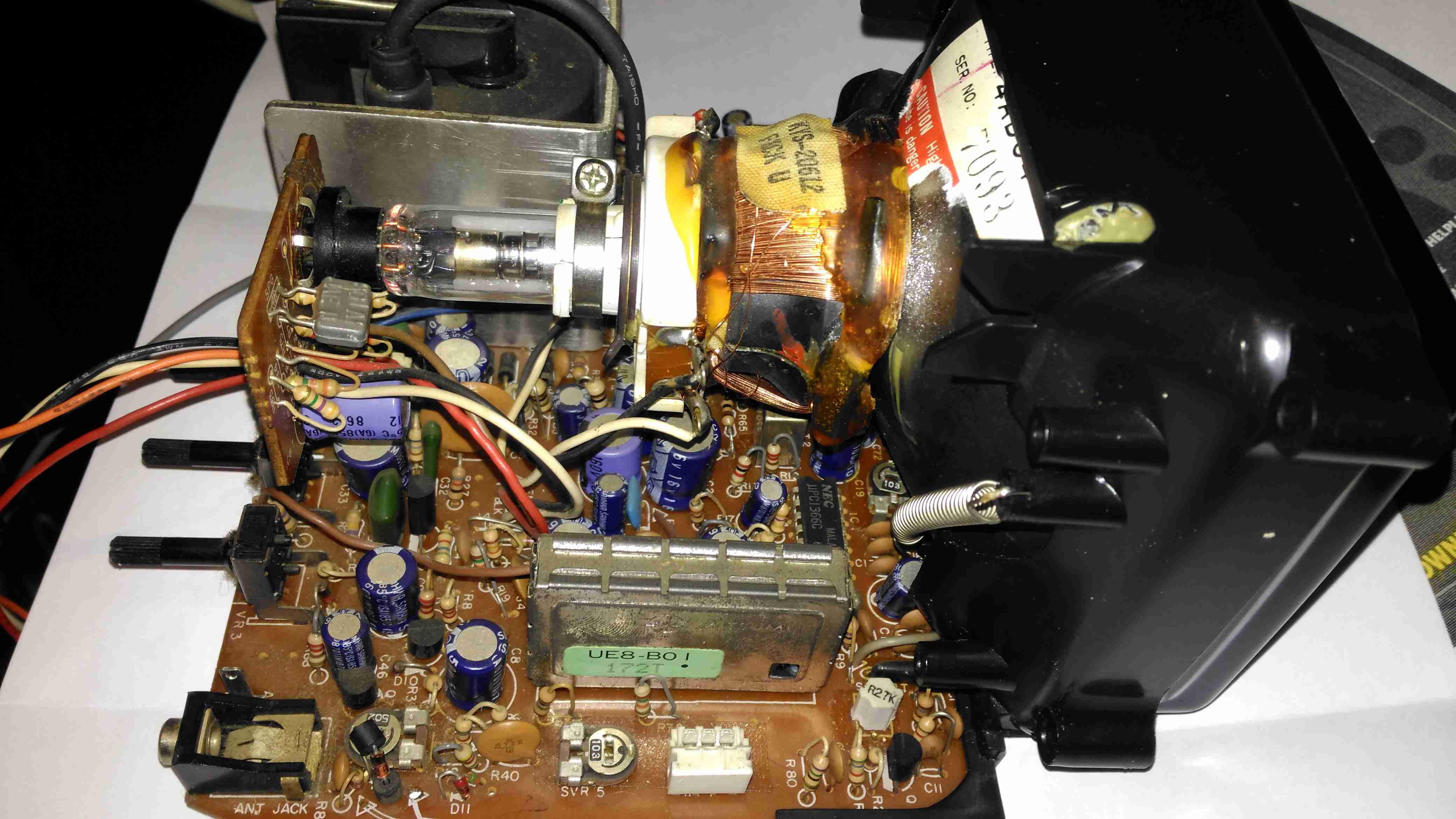
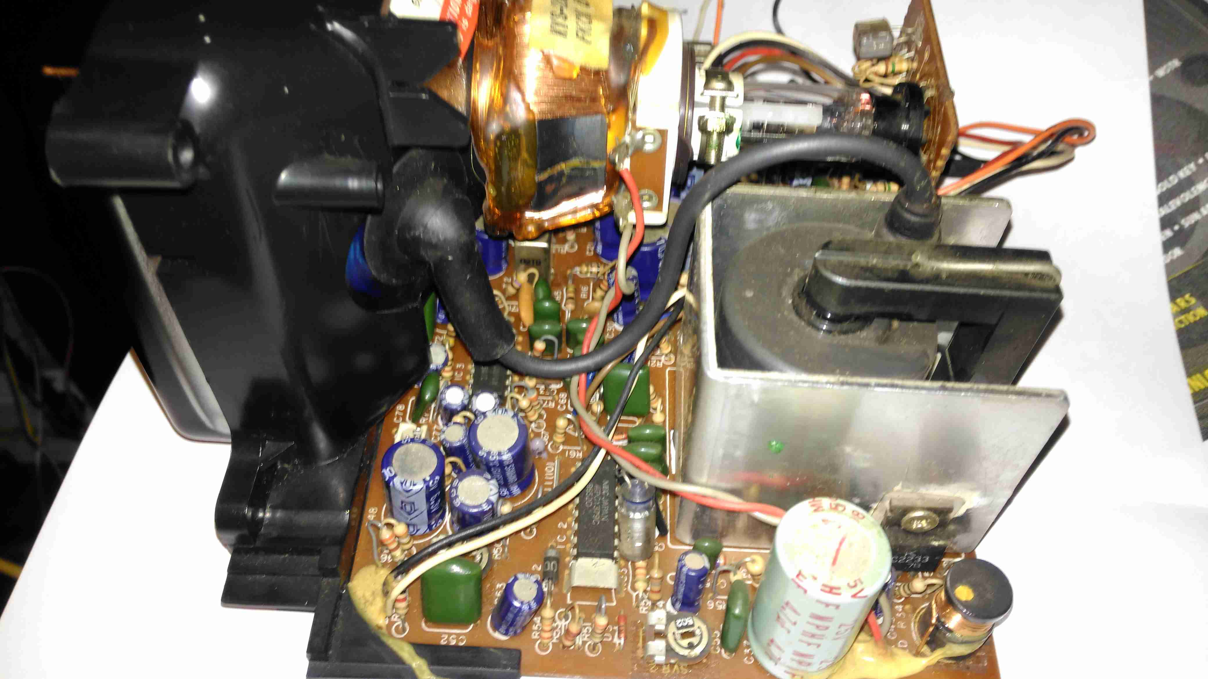
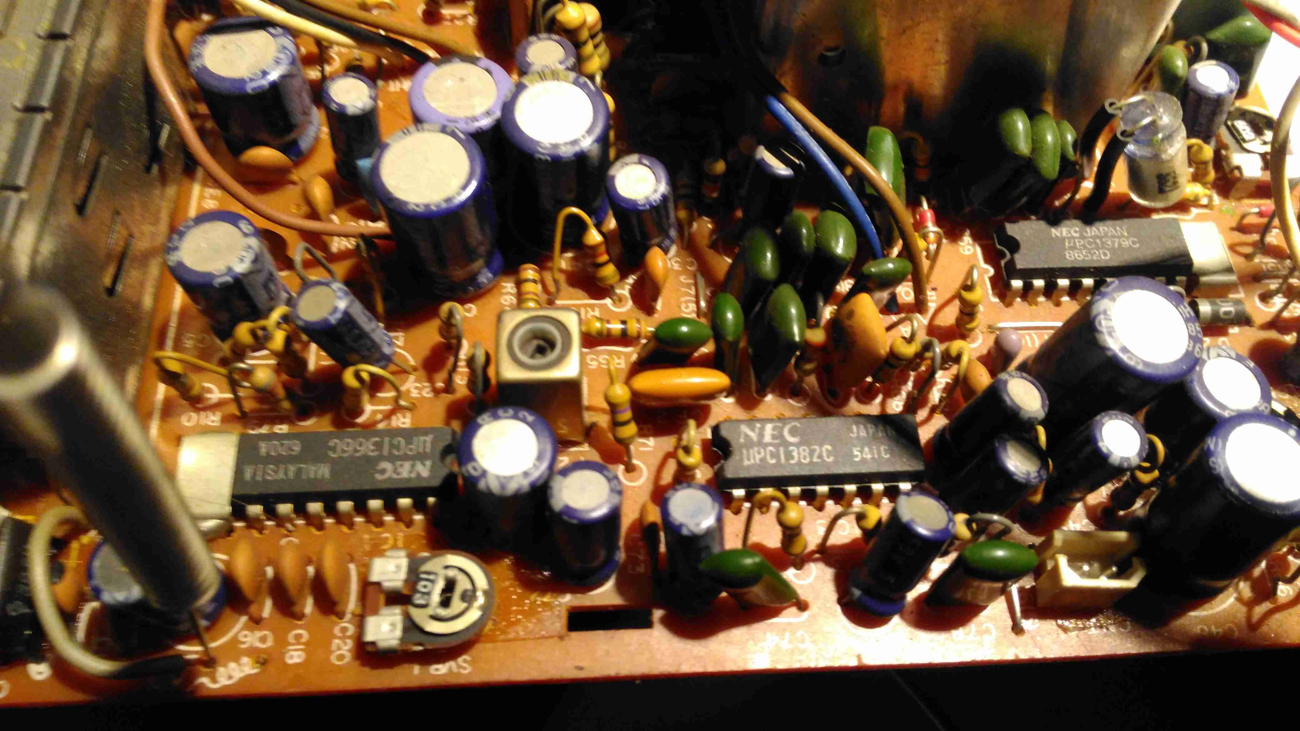
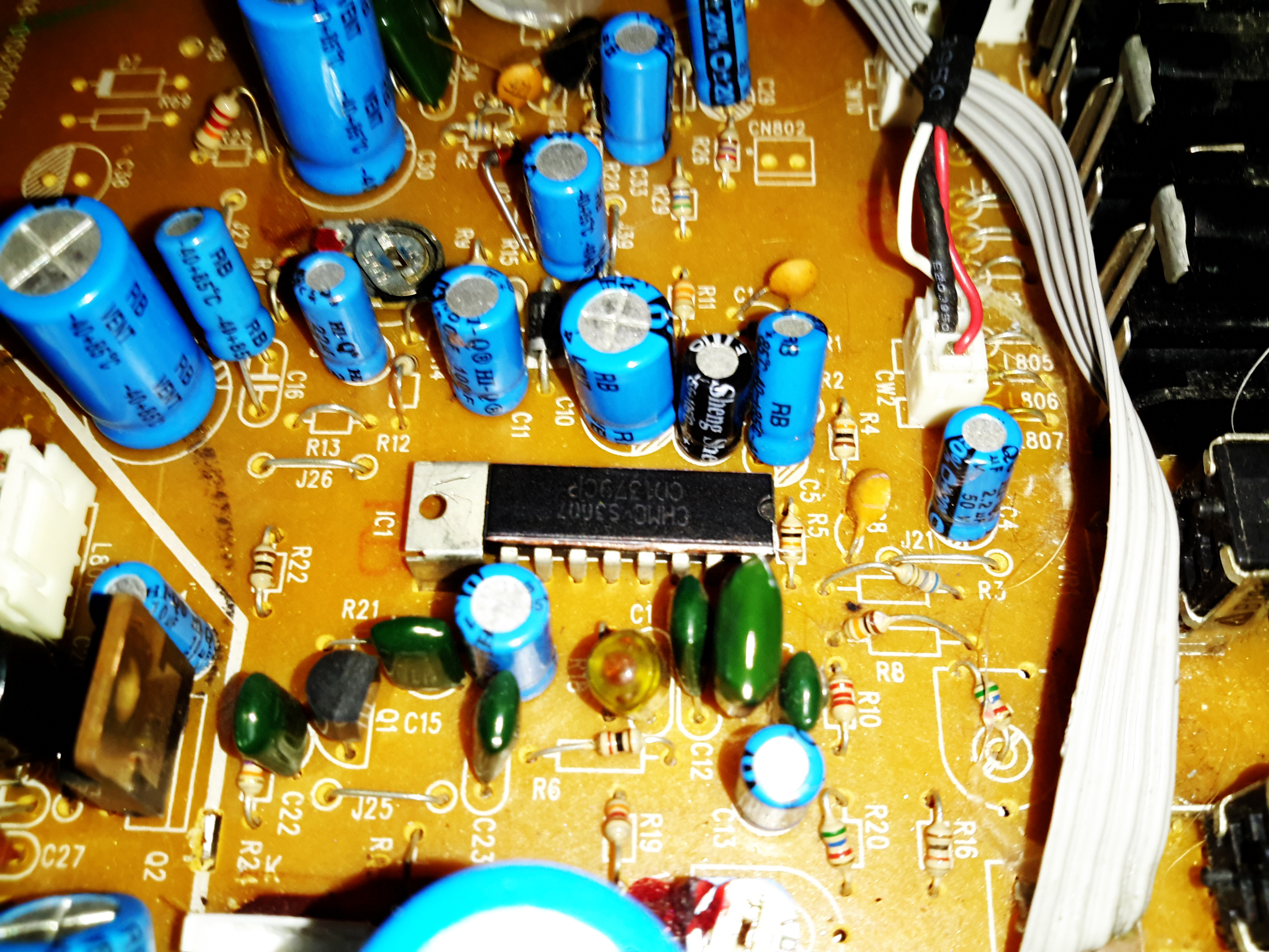
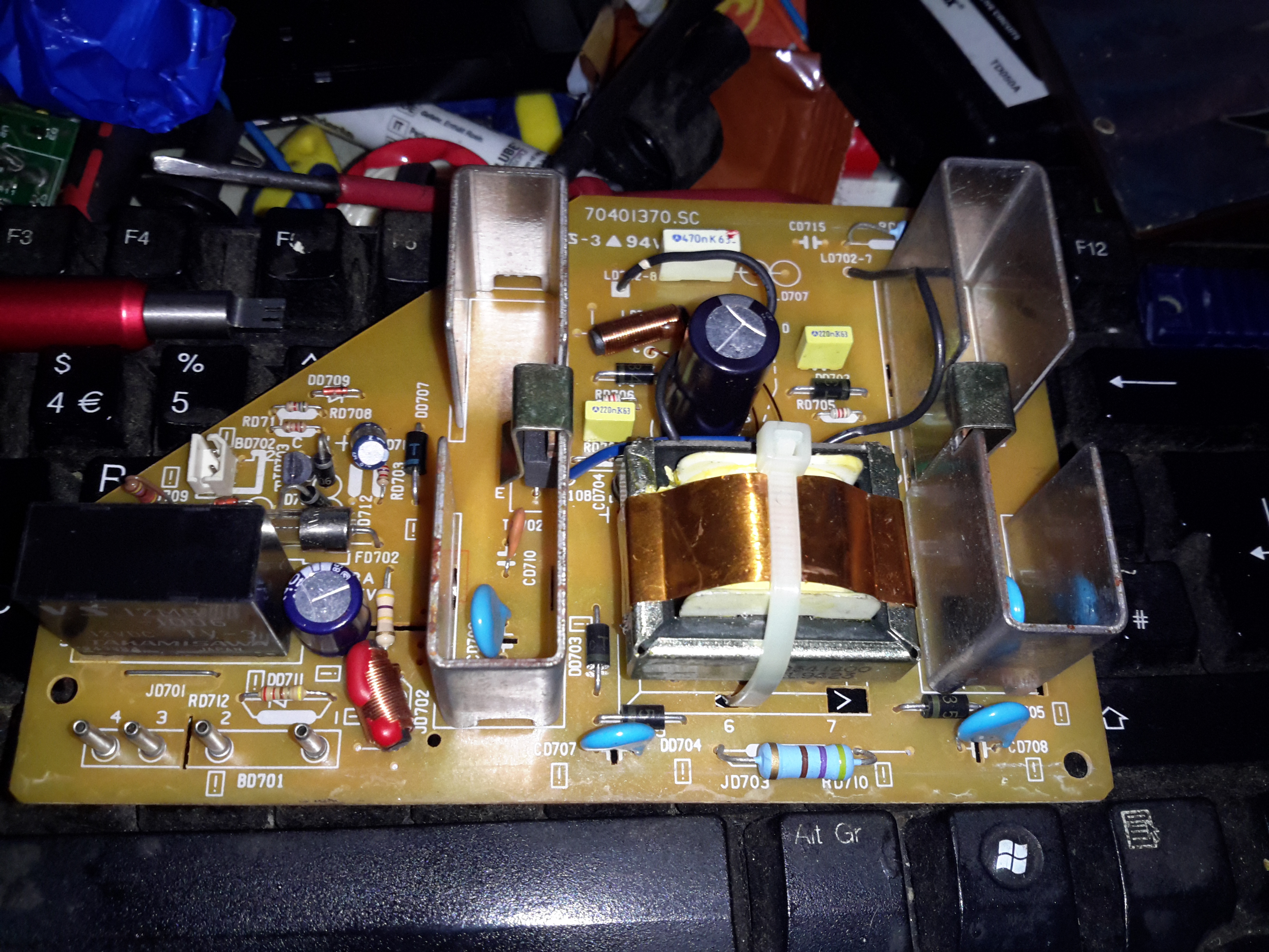
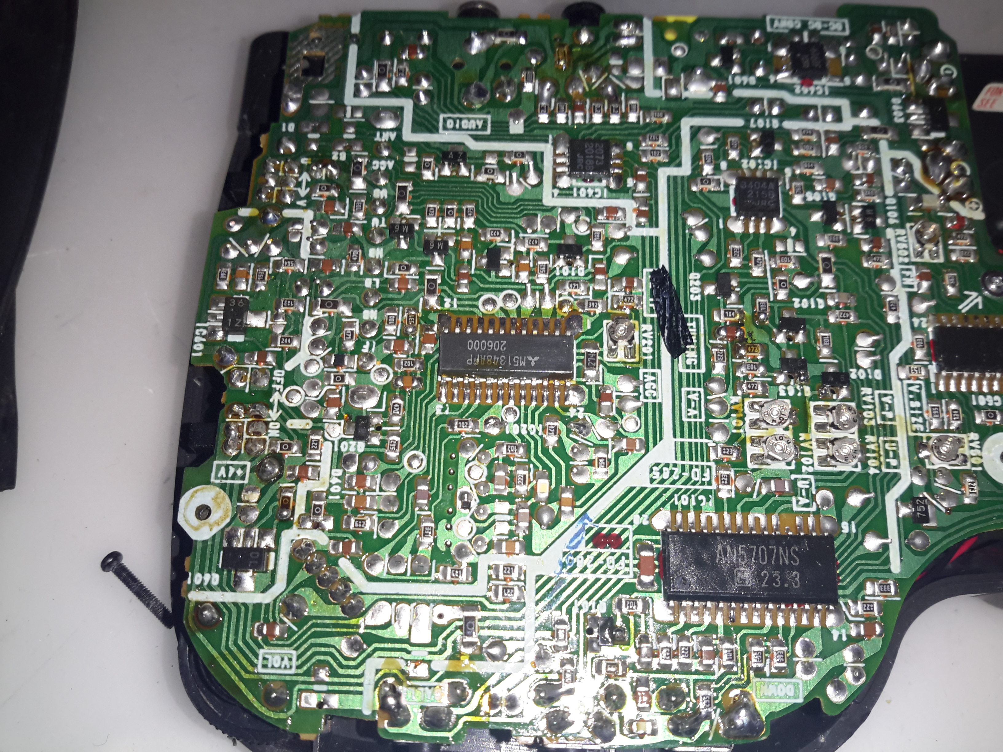
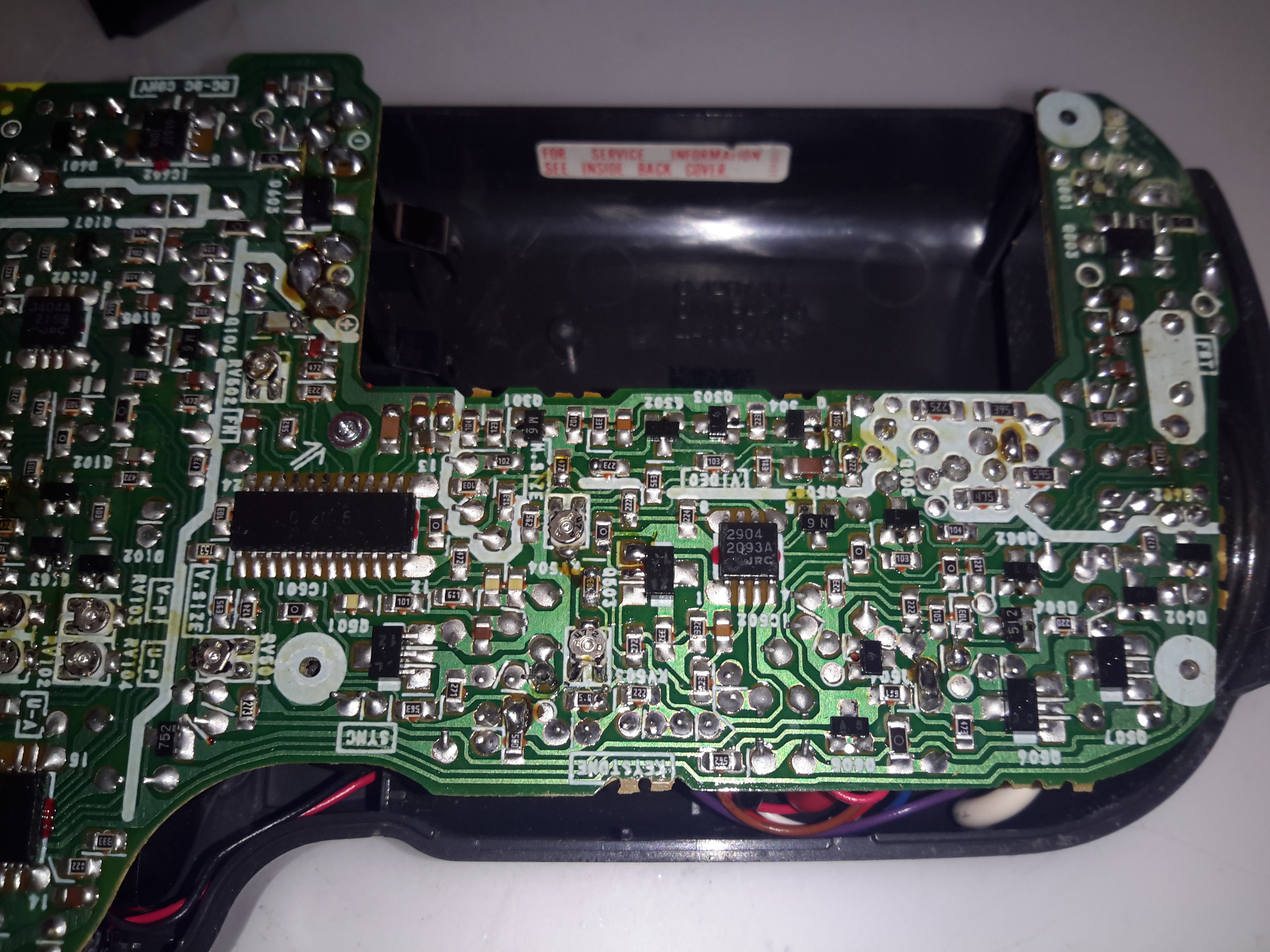
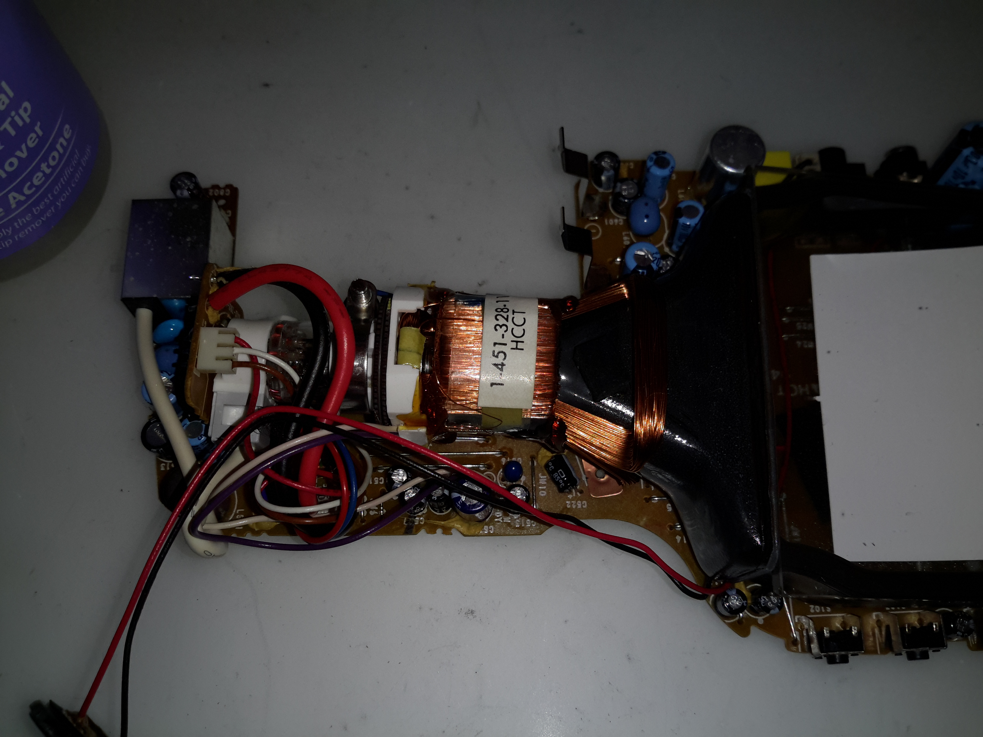
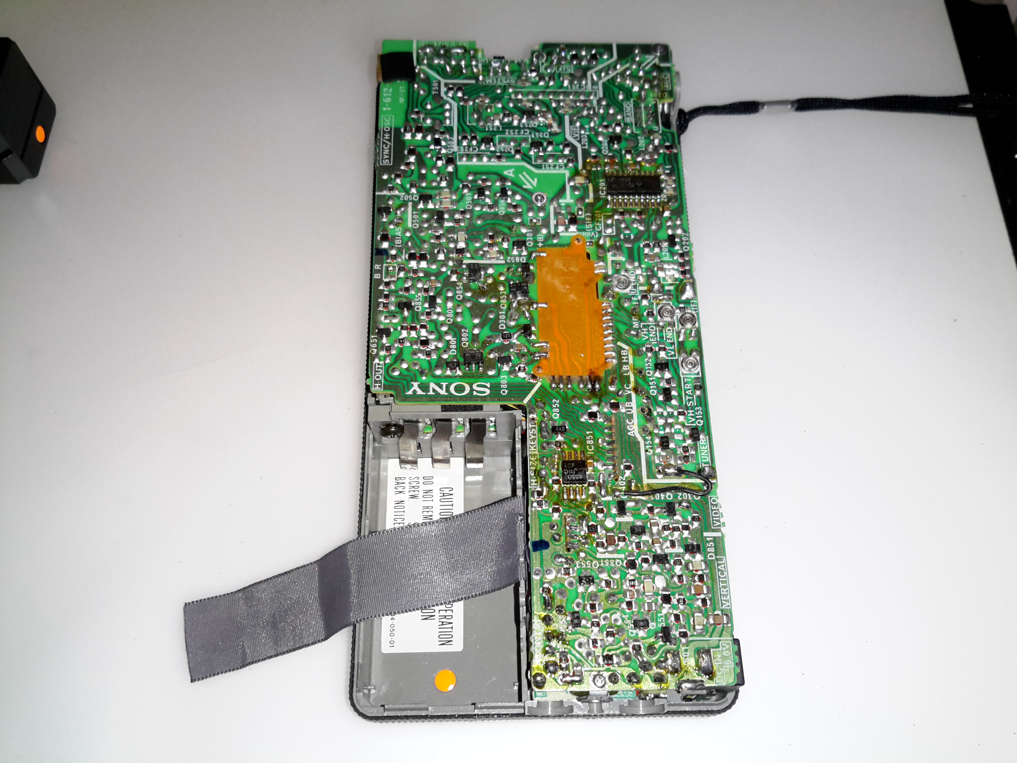
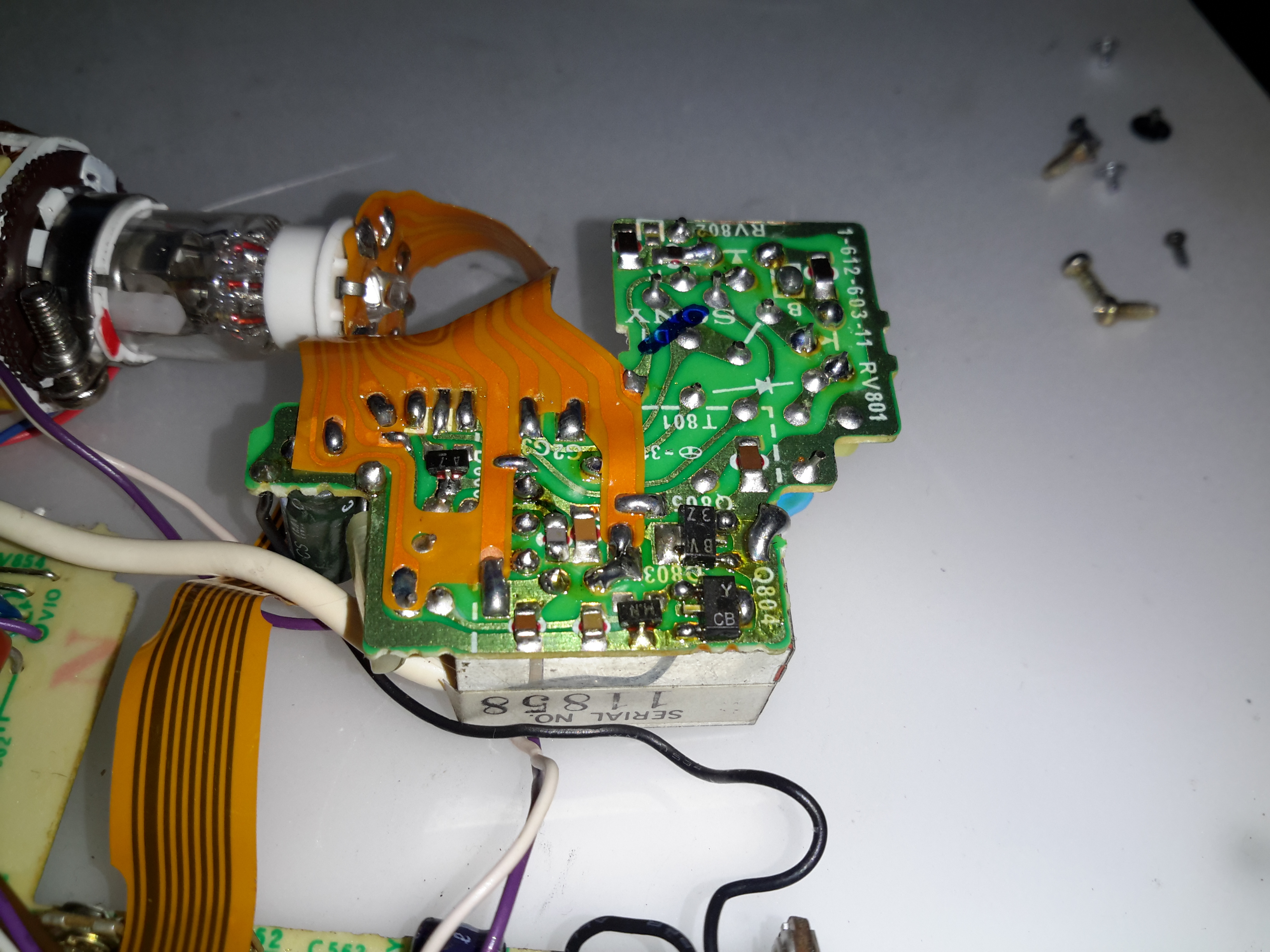
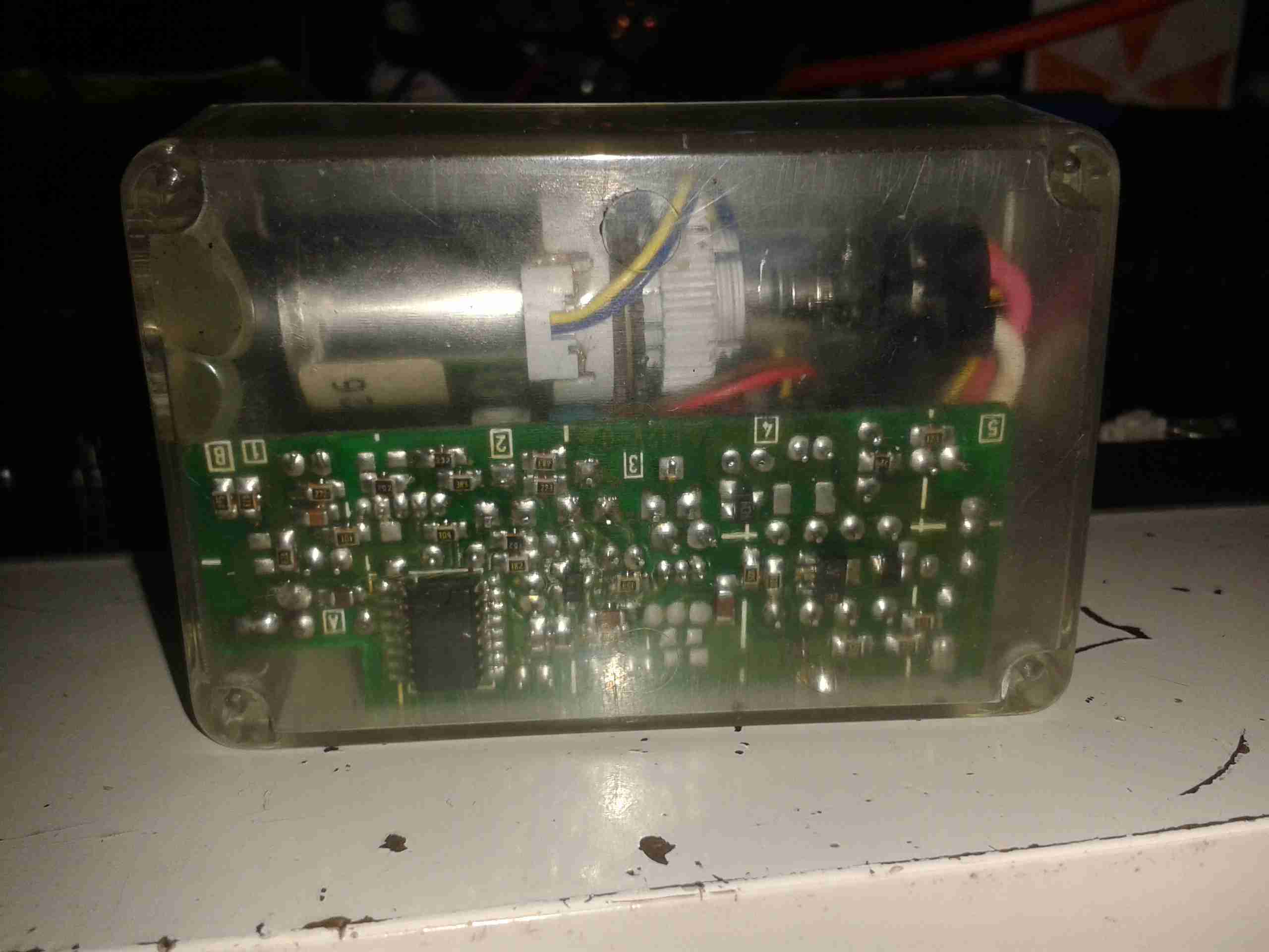
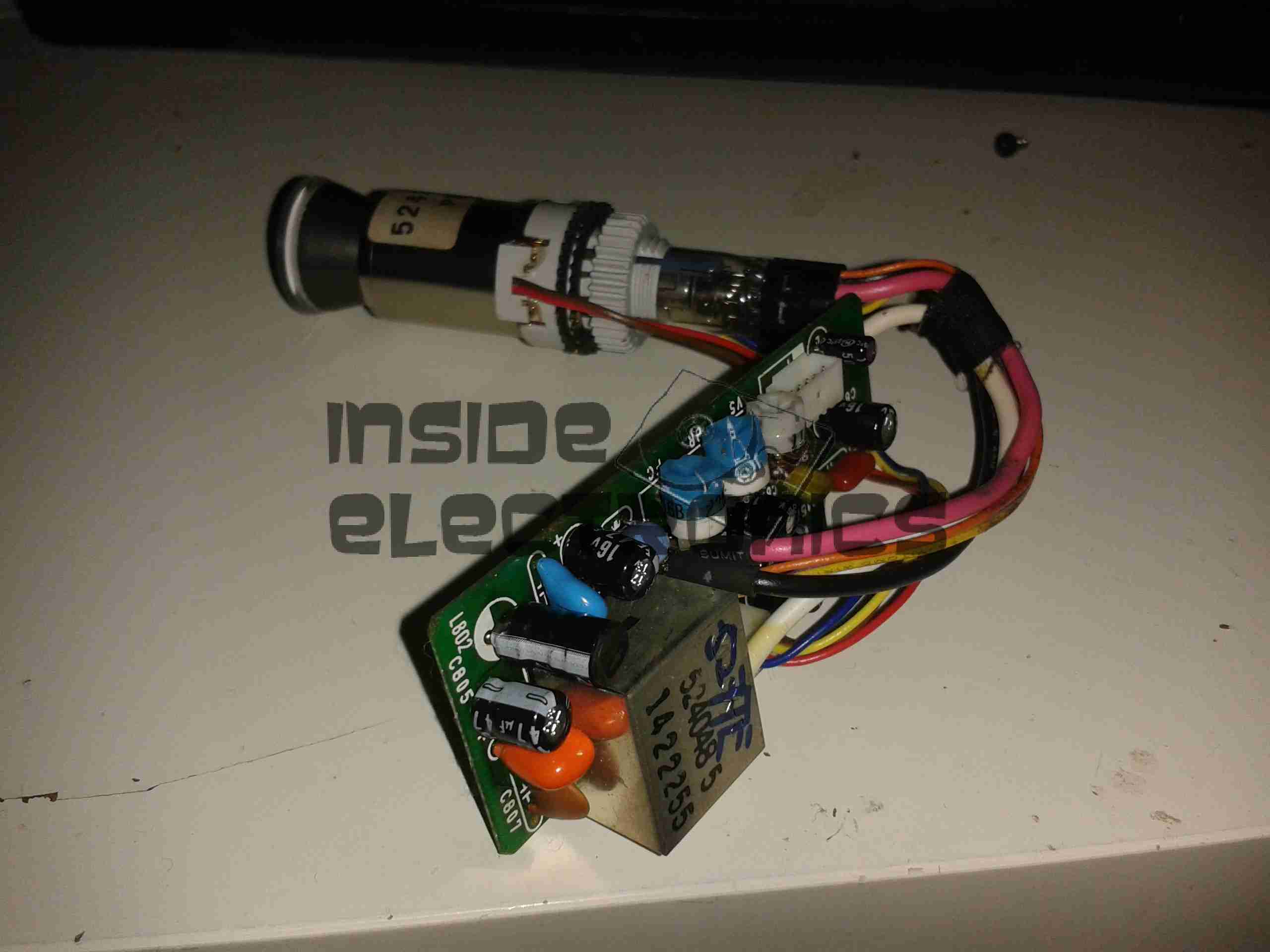
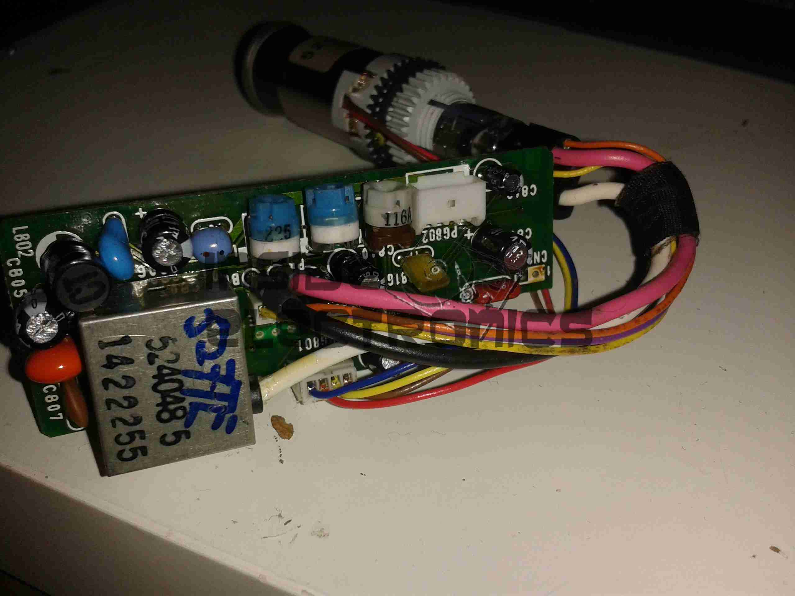
Separating the boards reveals the other two PCBs, the Video & Horizontal/HV boards. The bottom board takes care of the Horizontal output, and the lefthand board the video input, sync separation & amplification.

Horizontal Control IC

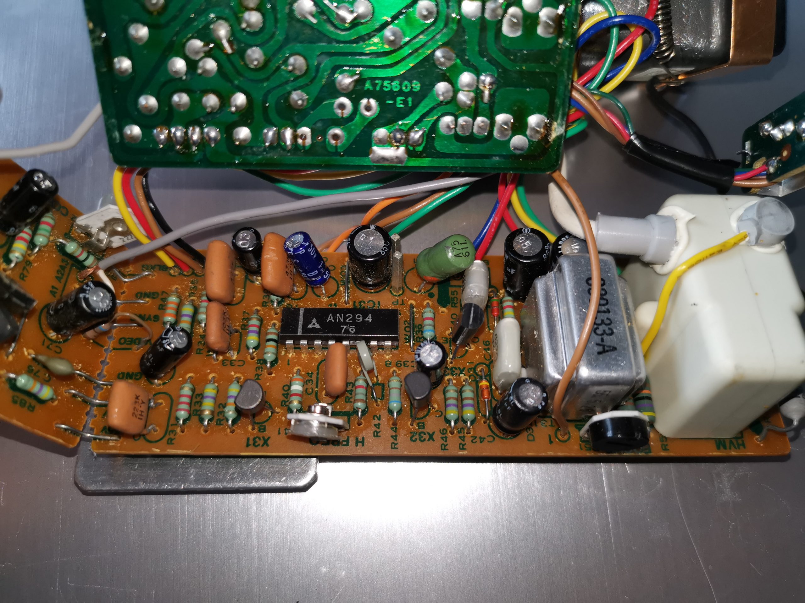
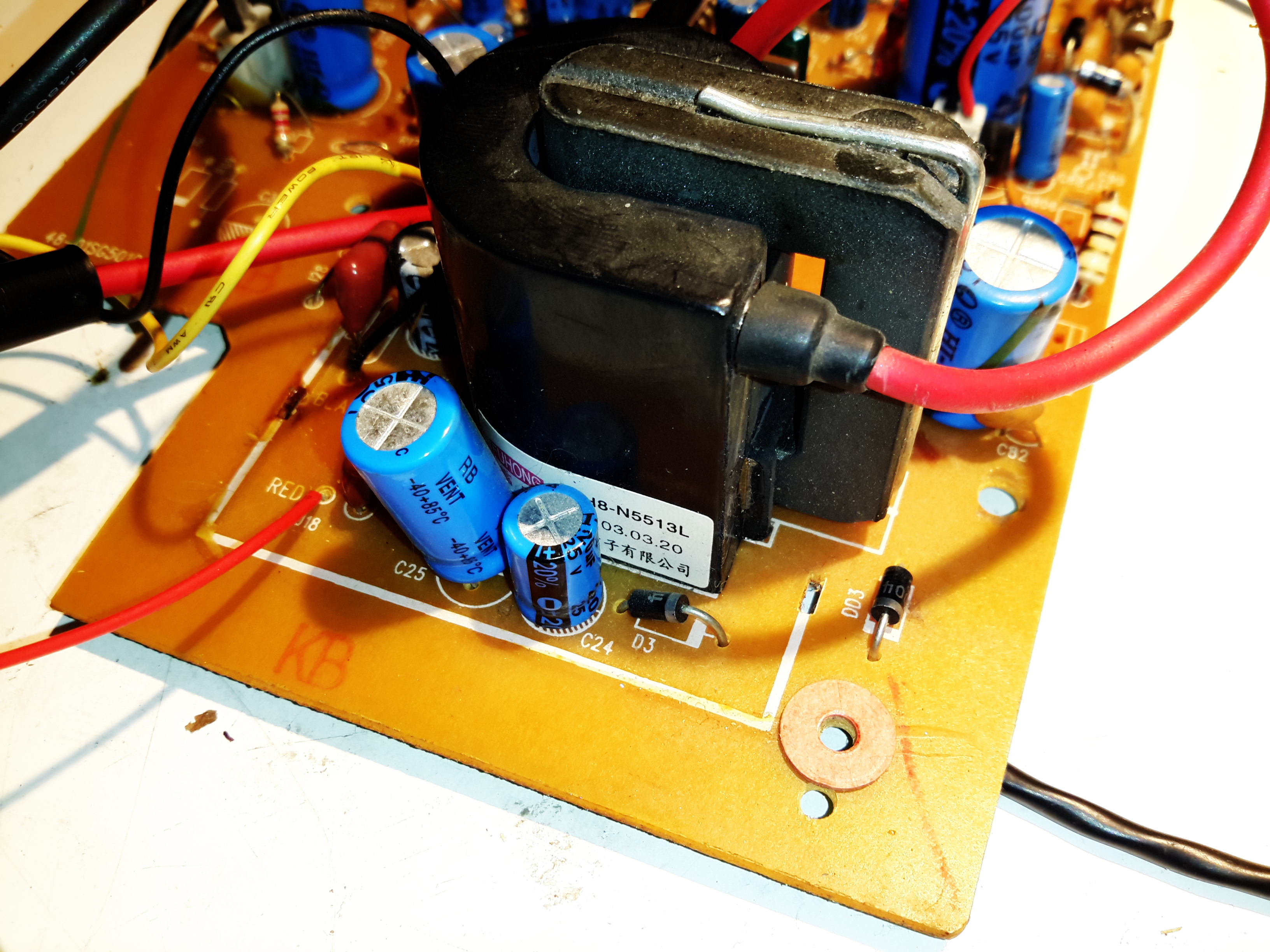
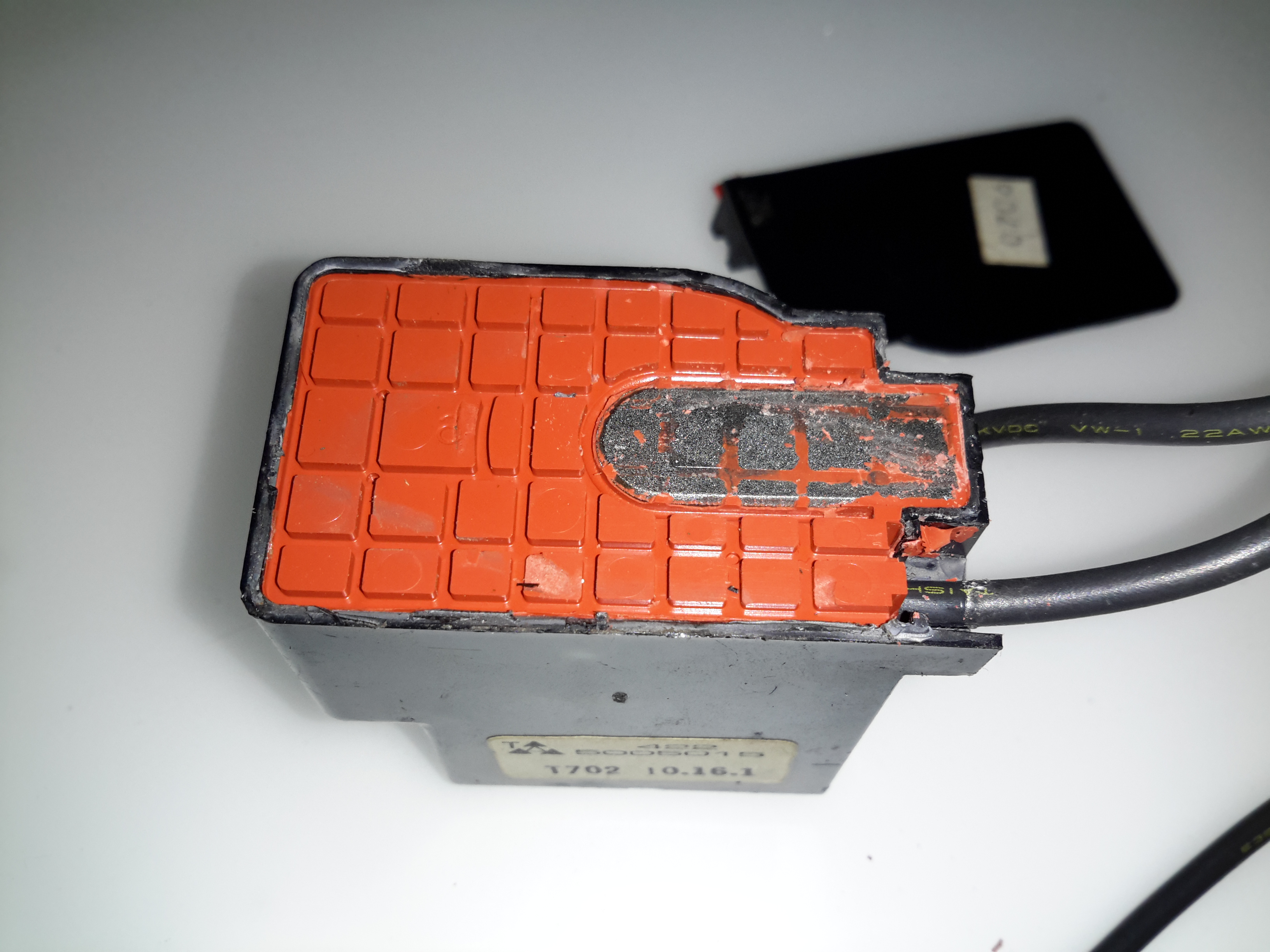
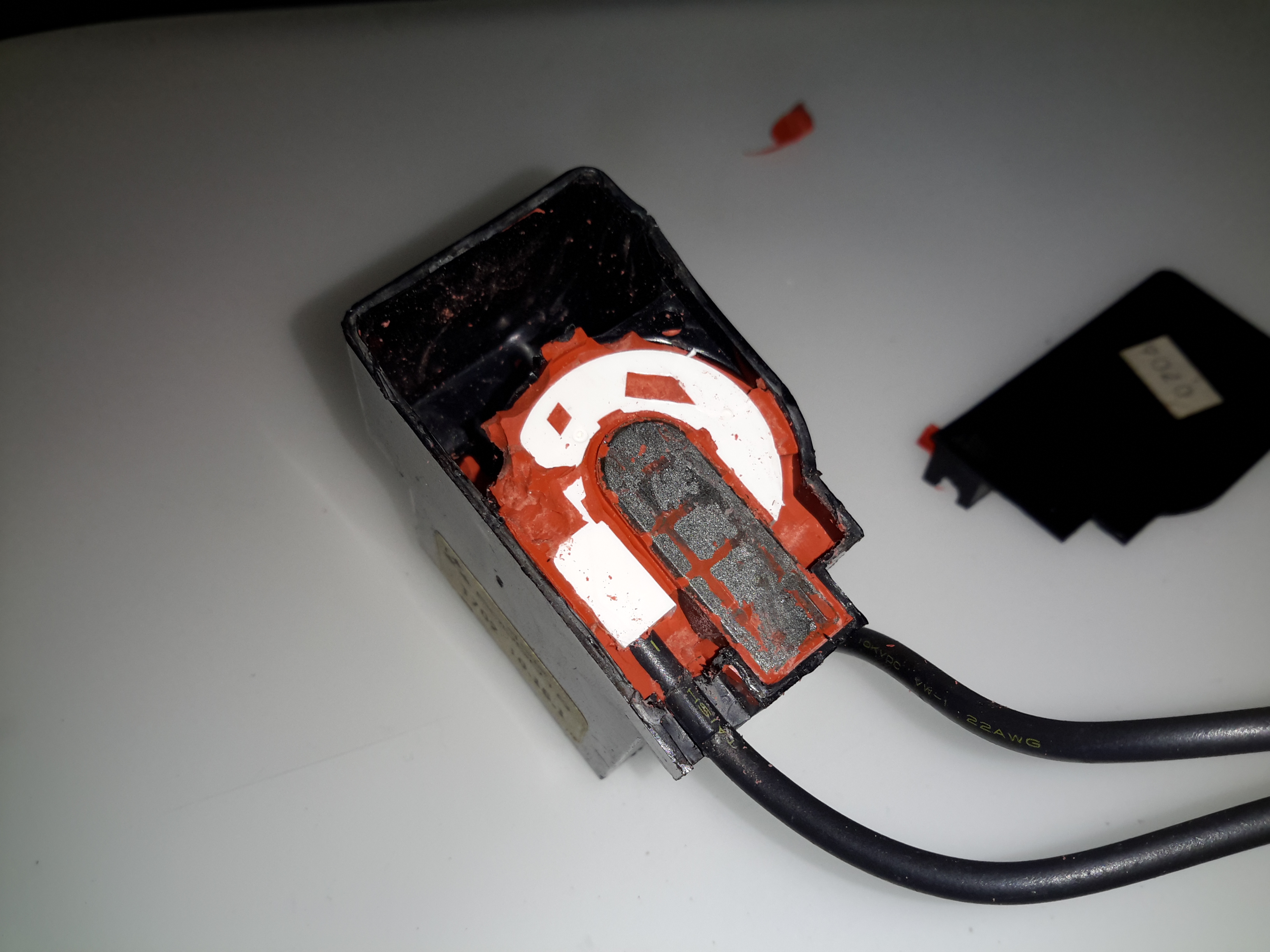
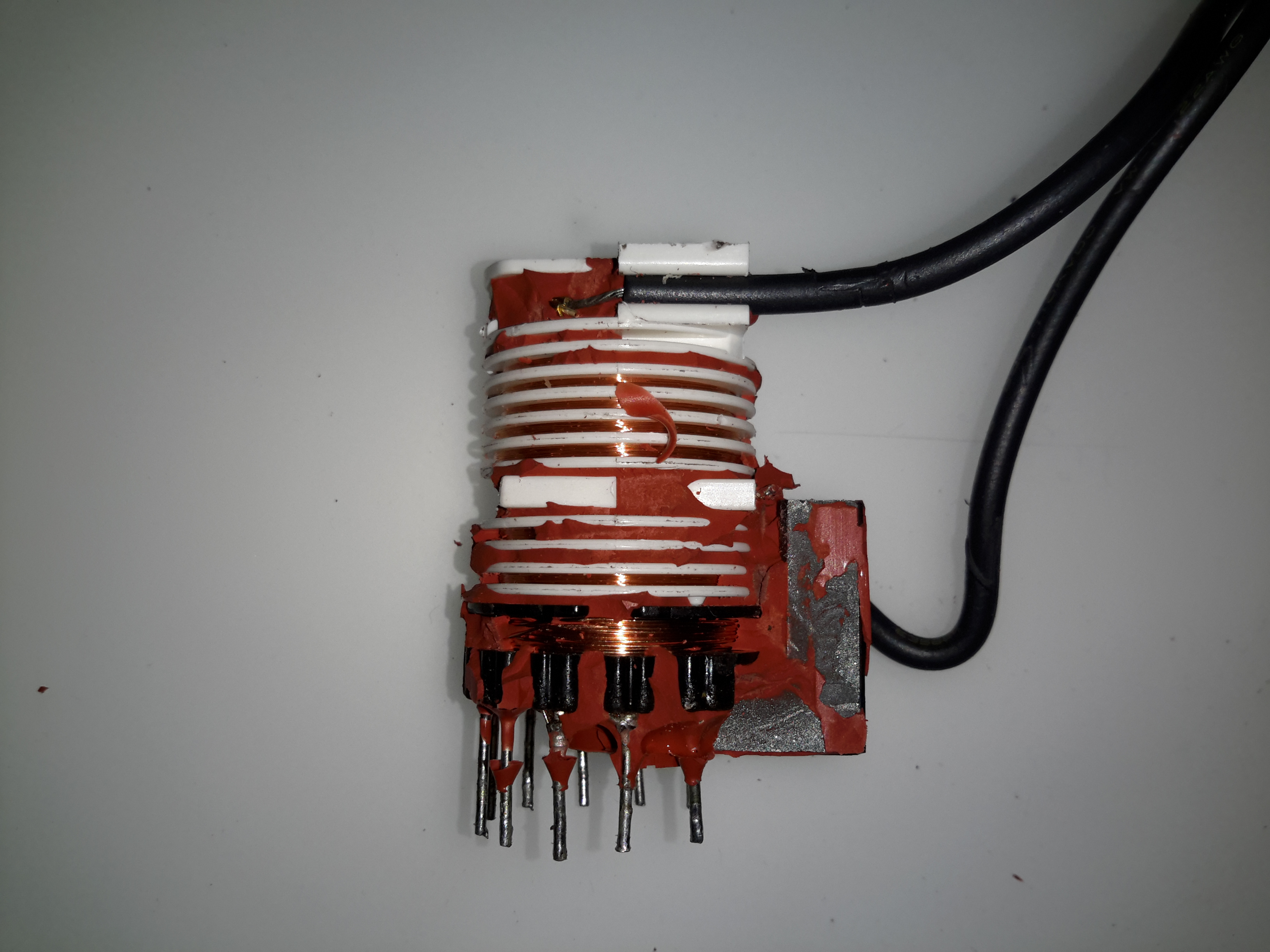
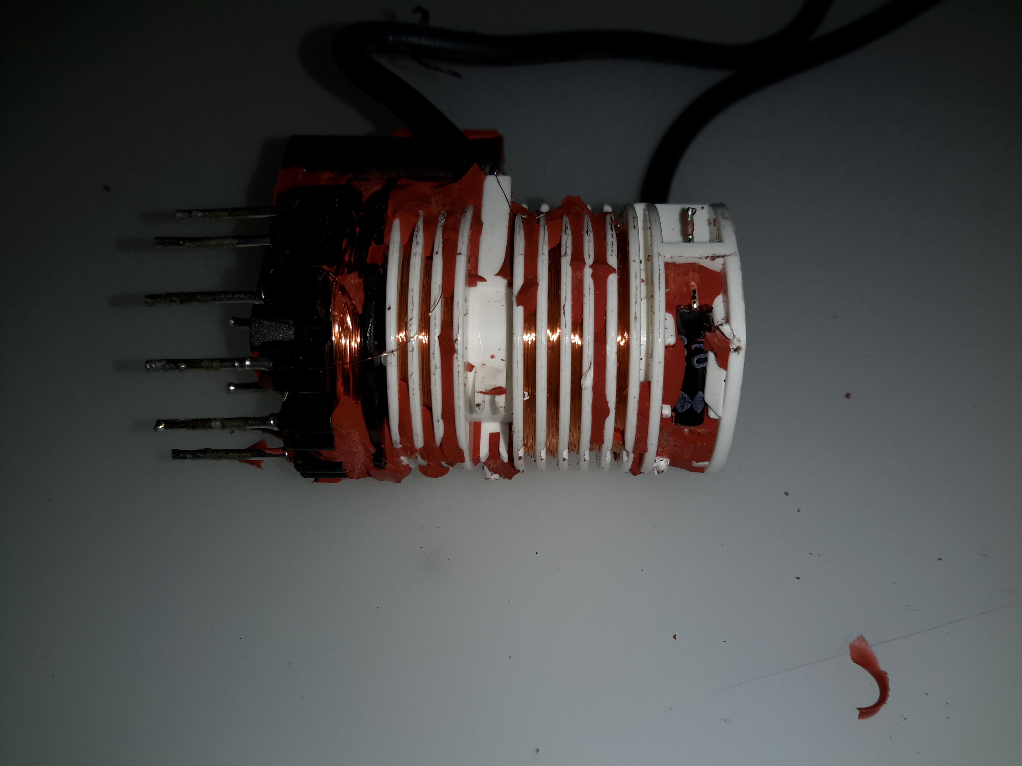
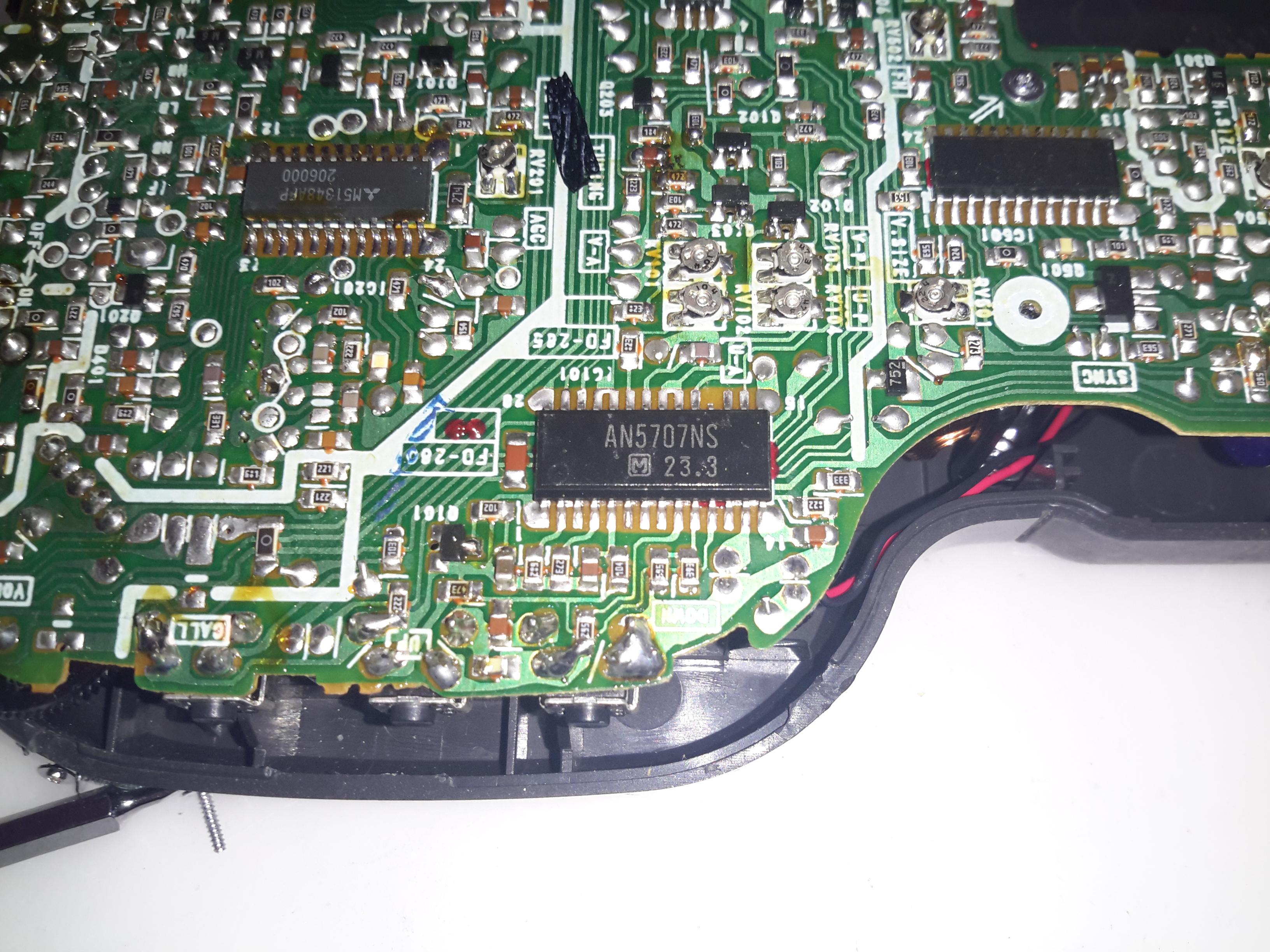
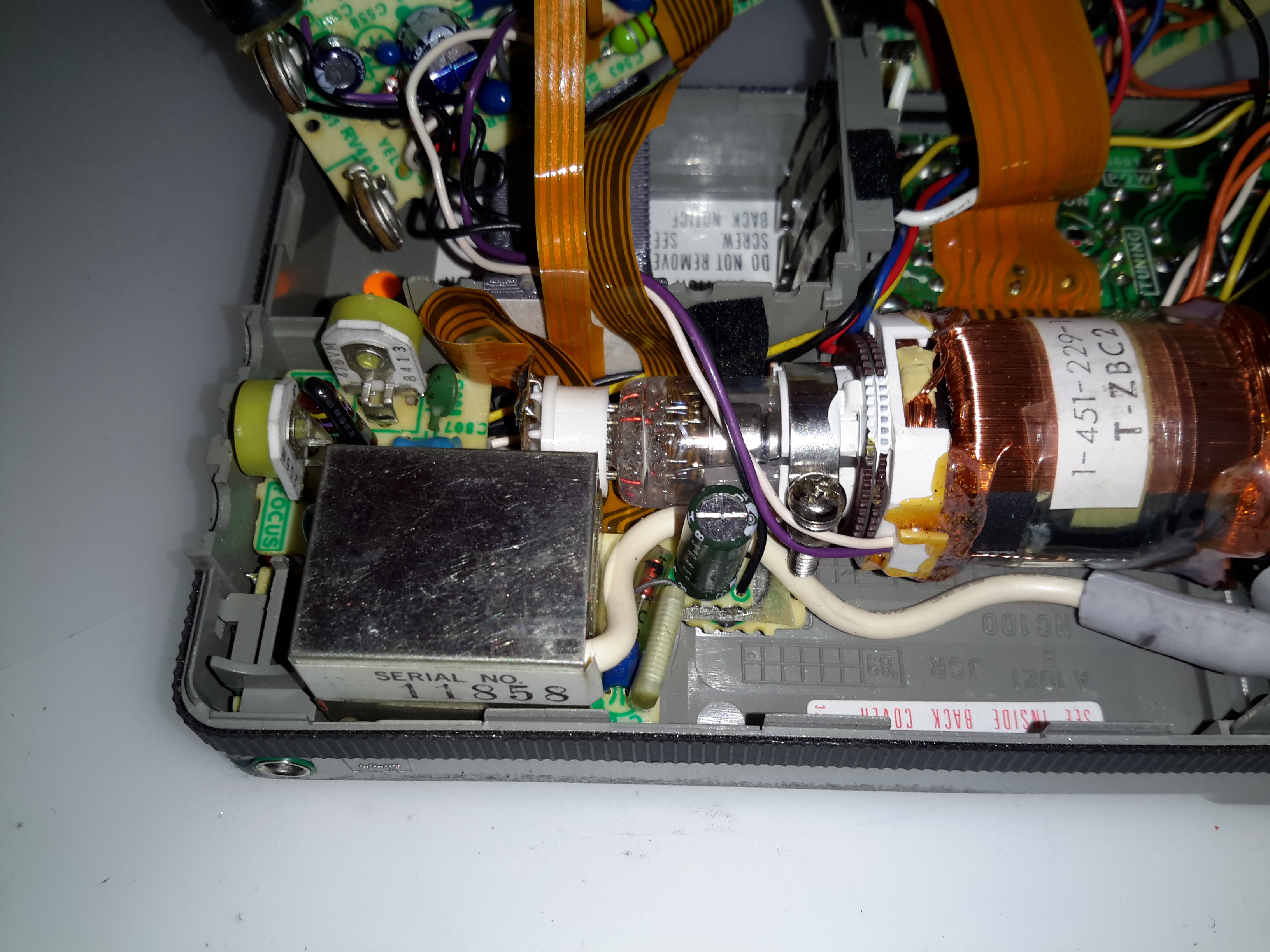
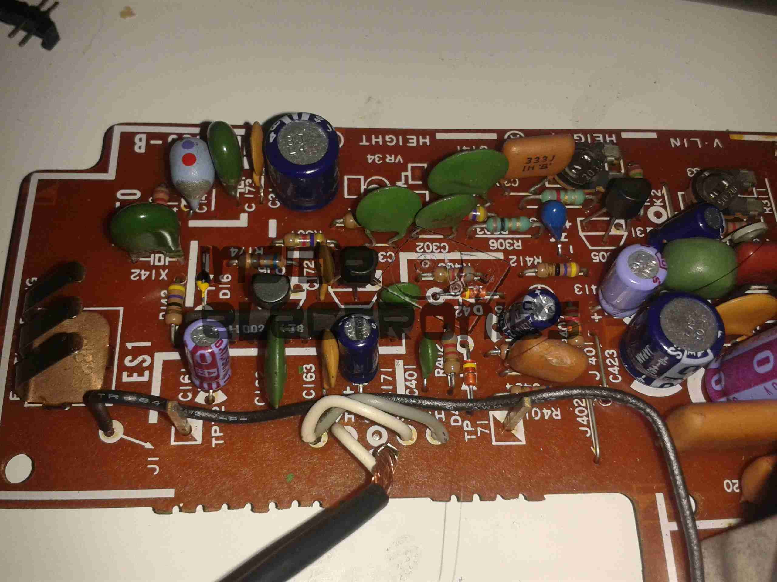
The Horizontal section is controlled by a Matsushita AN294 device. Unfortunately I haven’t been able to locate a datasheet for this one. The flyback transformer (Horizontal Output) is on the right, with another smaller transformer I don’t quite know the purpose of. Oddly, there’s no large switching transistor for the horizontal output stage – as the PCB notes the flyback as being a “HVM” this may in fact be more tightly integrated with some of the drive circuitry in the potting. There aren’t anywhere near as many pins on it as a usual CRT flyback has either.
This section also generates the other voltages required by the CRT – 2.8v for the filament, and ~80v & ~400v for the grids.

Video Board
Video Board

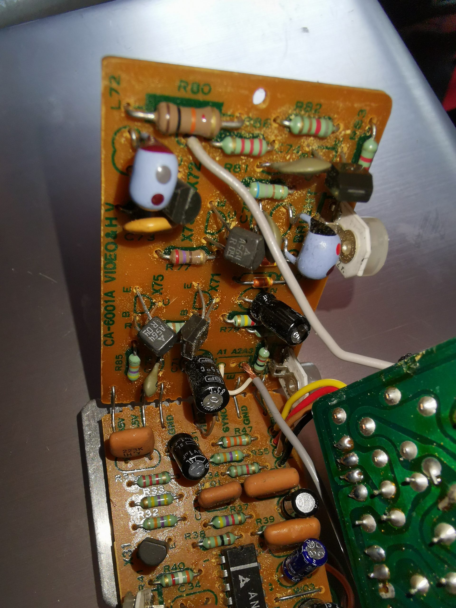
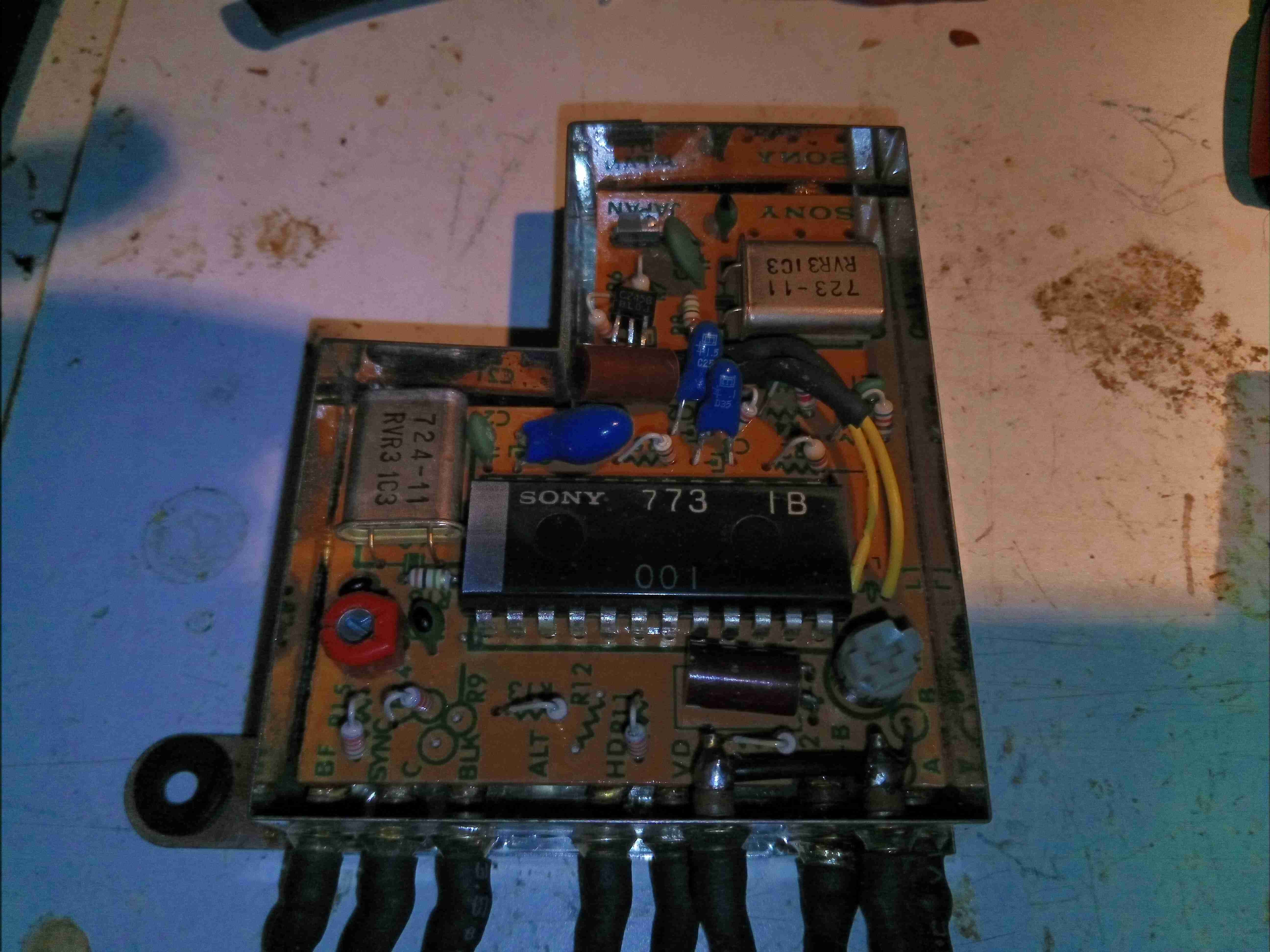
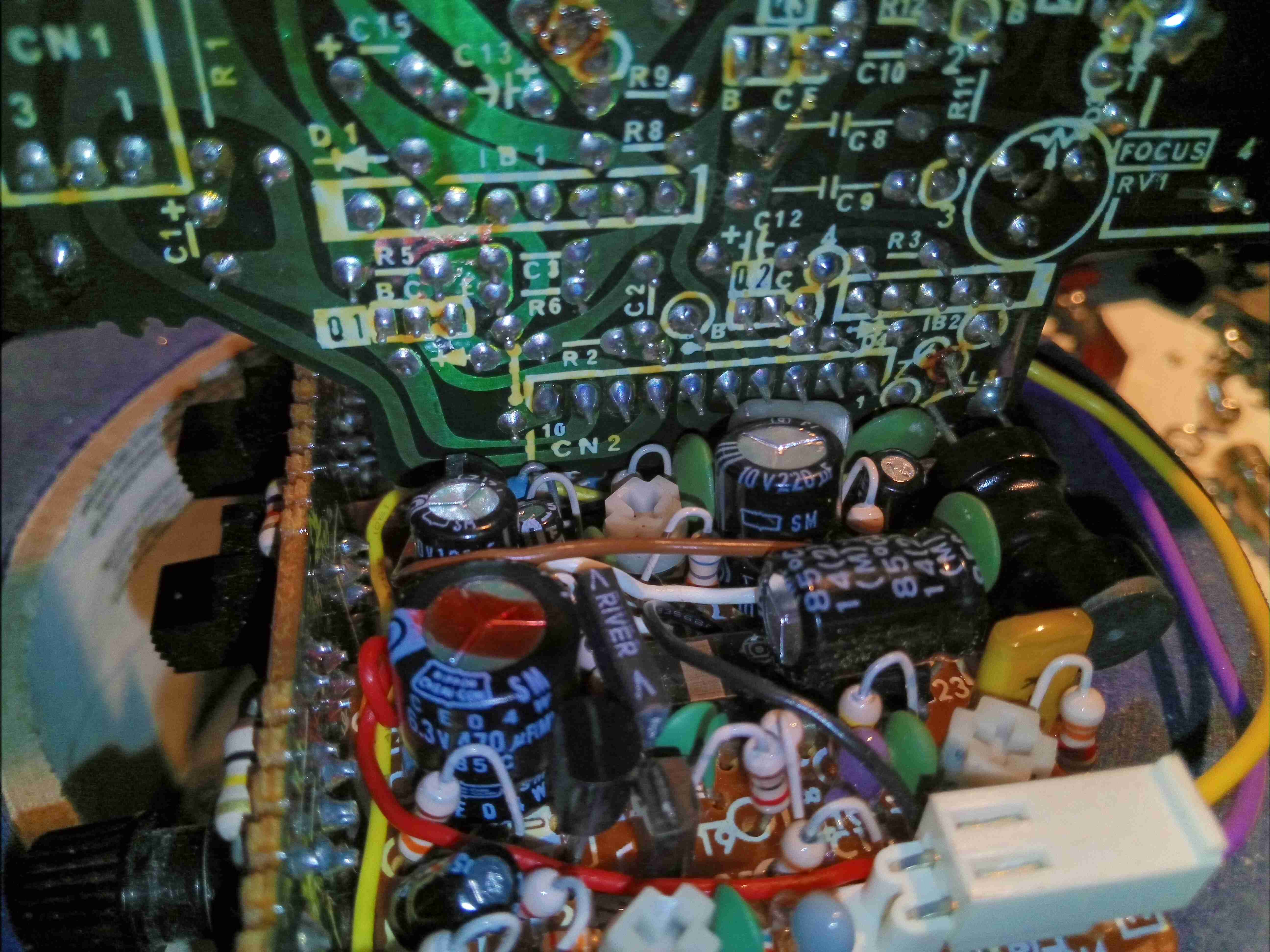
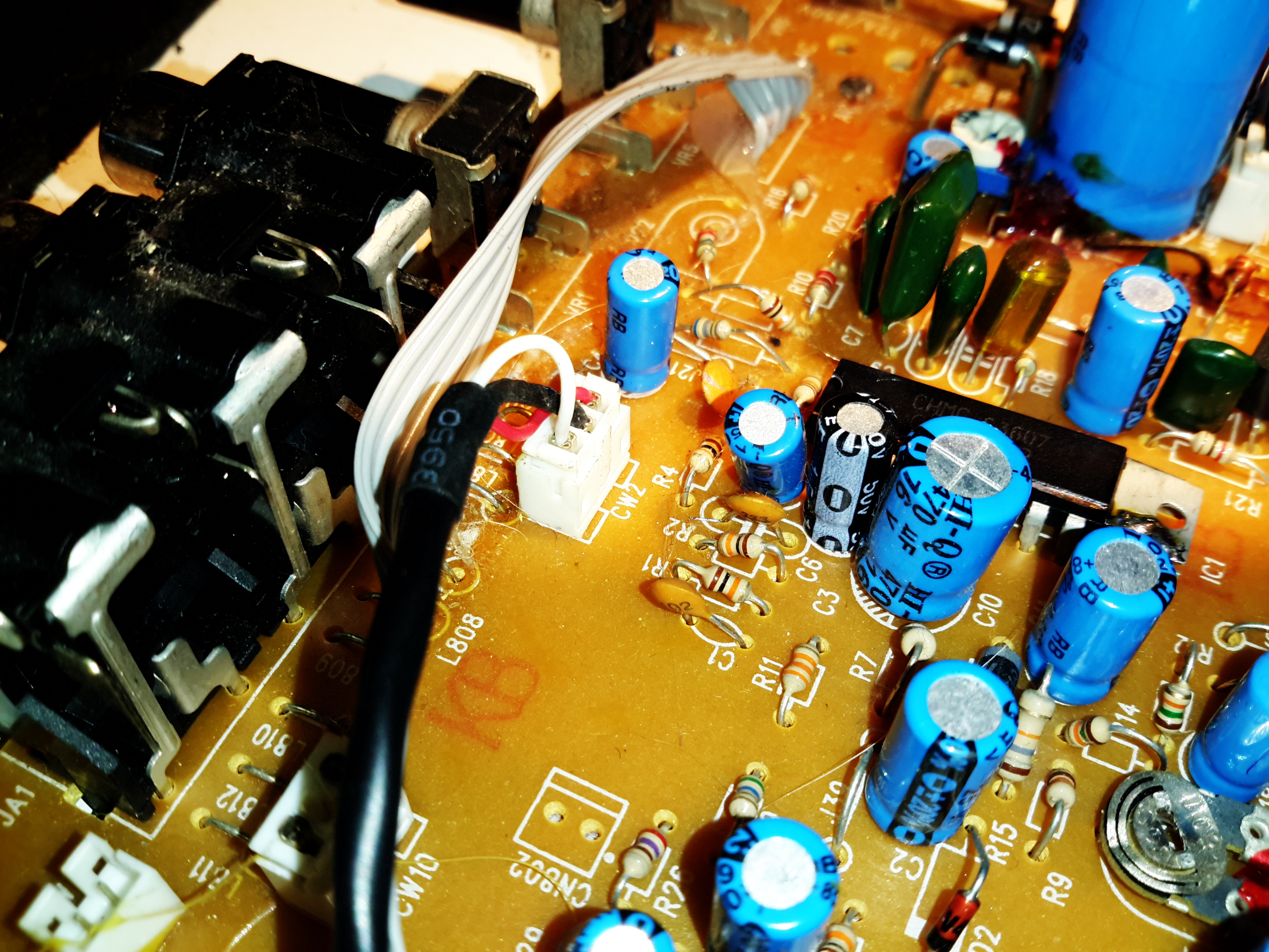
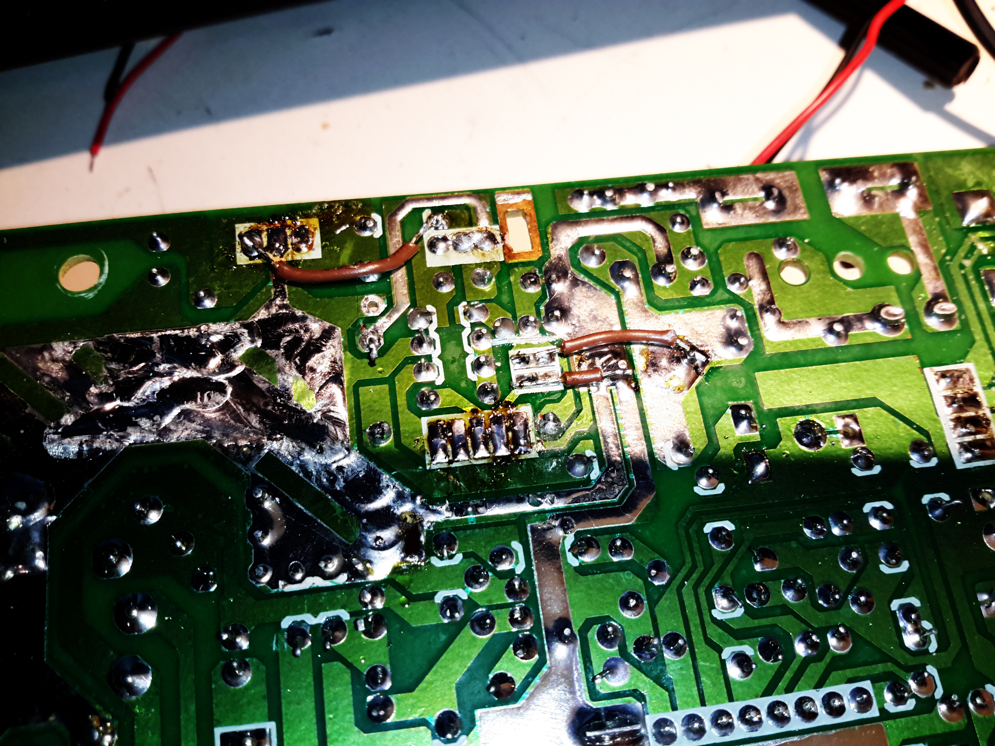
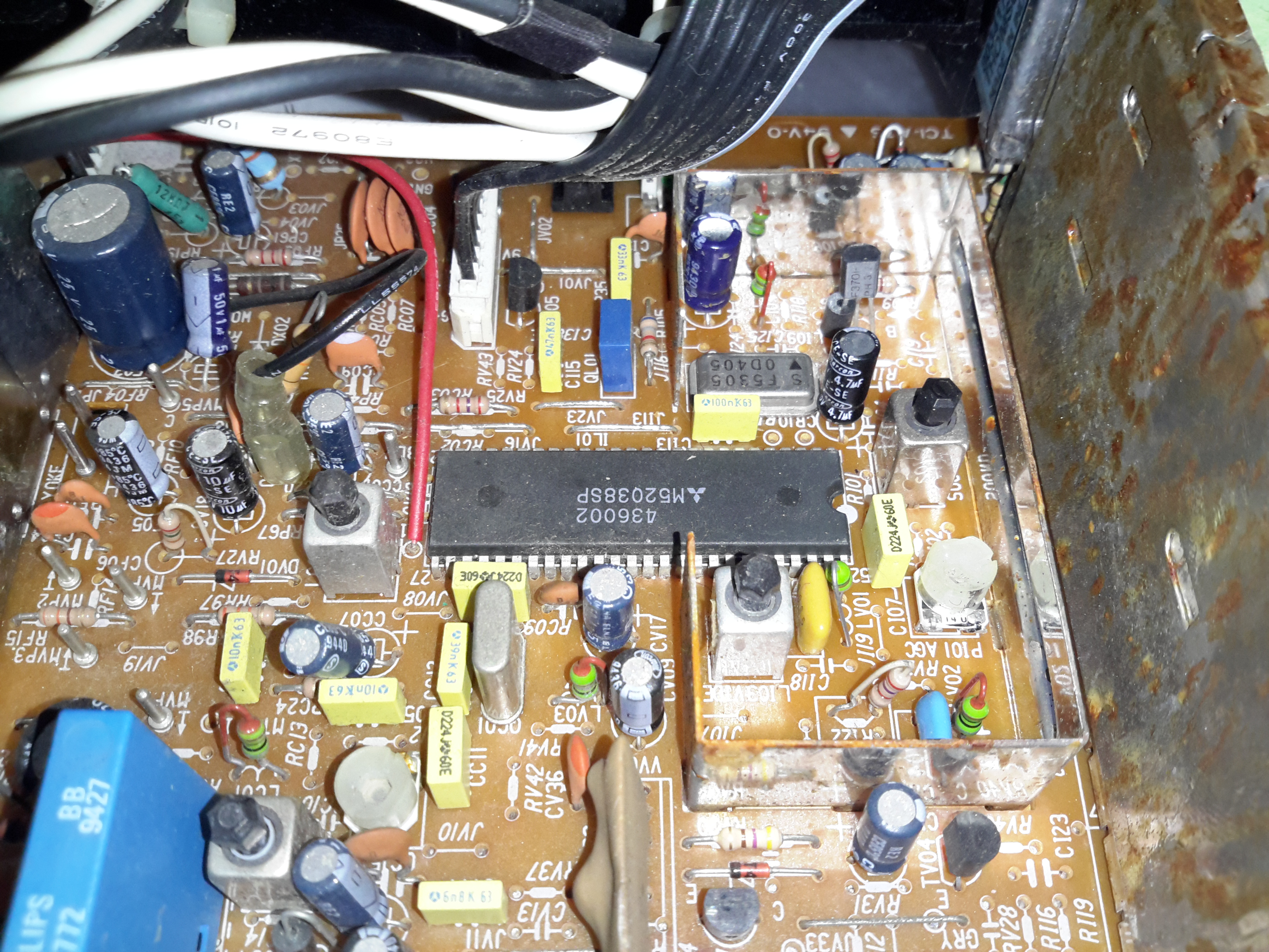
A closeup of the video board shows the relative simplicity. Only 4 transistors are doing all the video actions. There is relatively high voltage on here though – an 85v feed from the power supply which is the rail voltage for the video amplifier to the CRT cathode/G1.

Focus & Horizontal Hold Adjustments

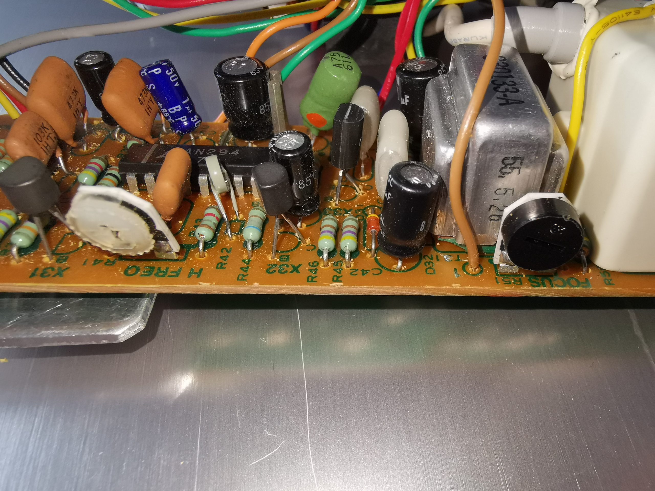
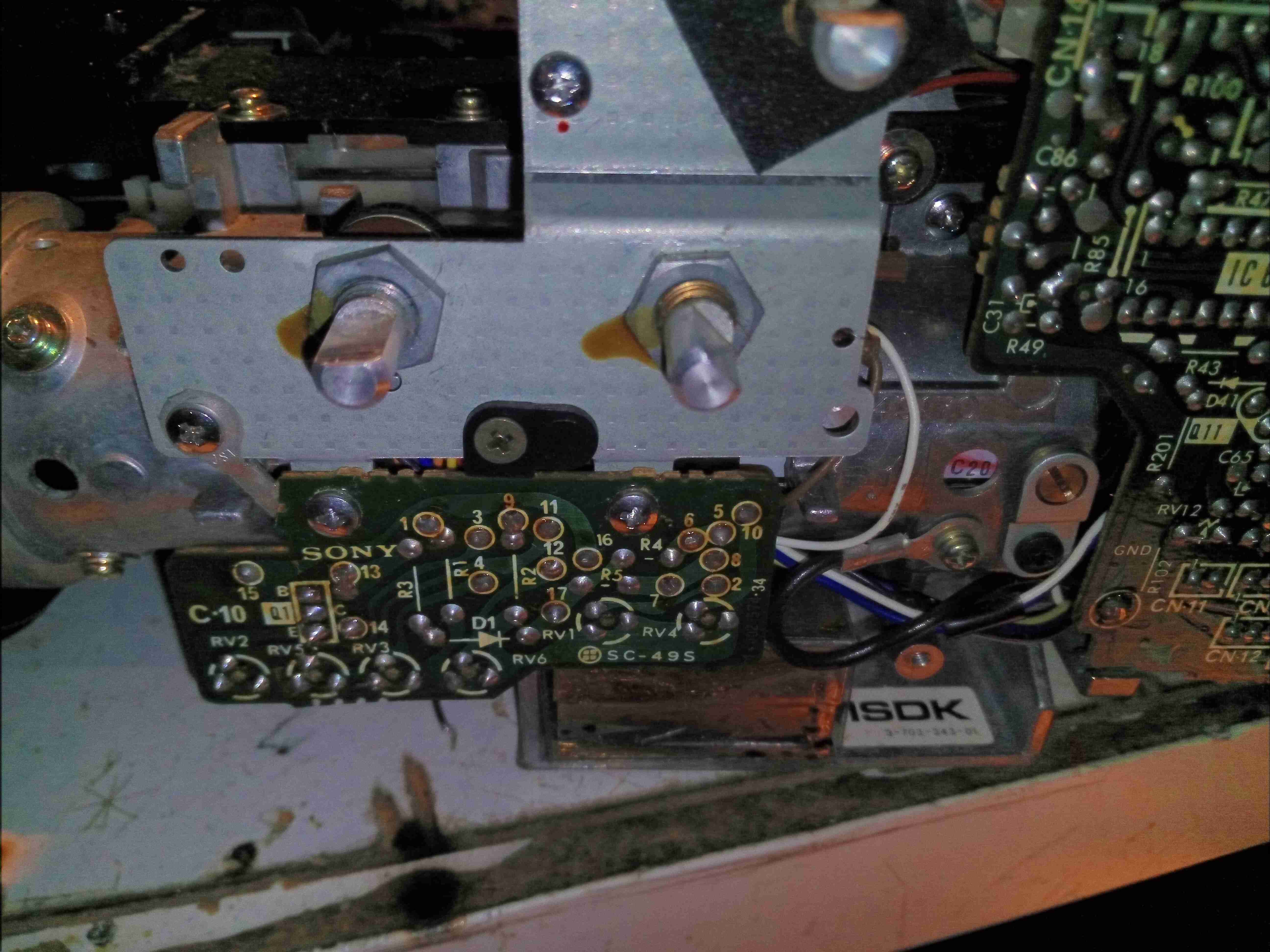
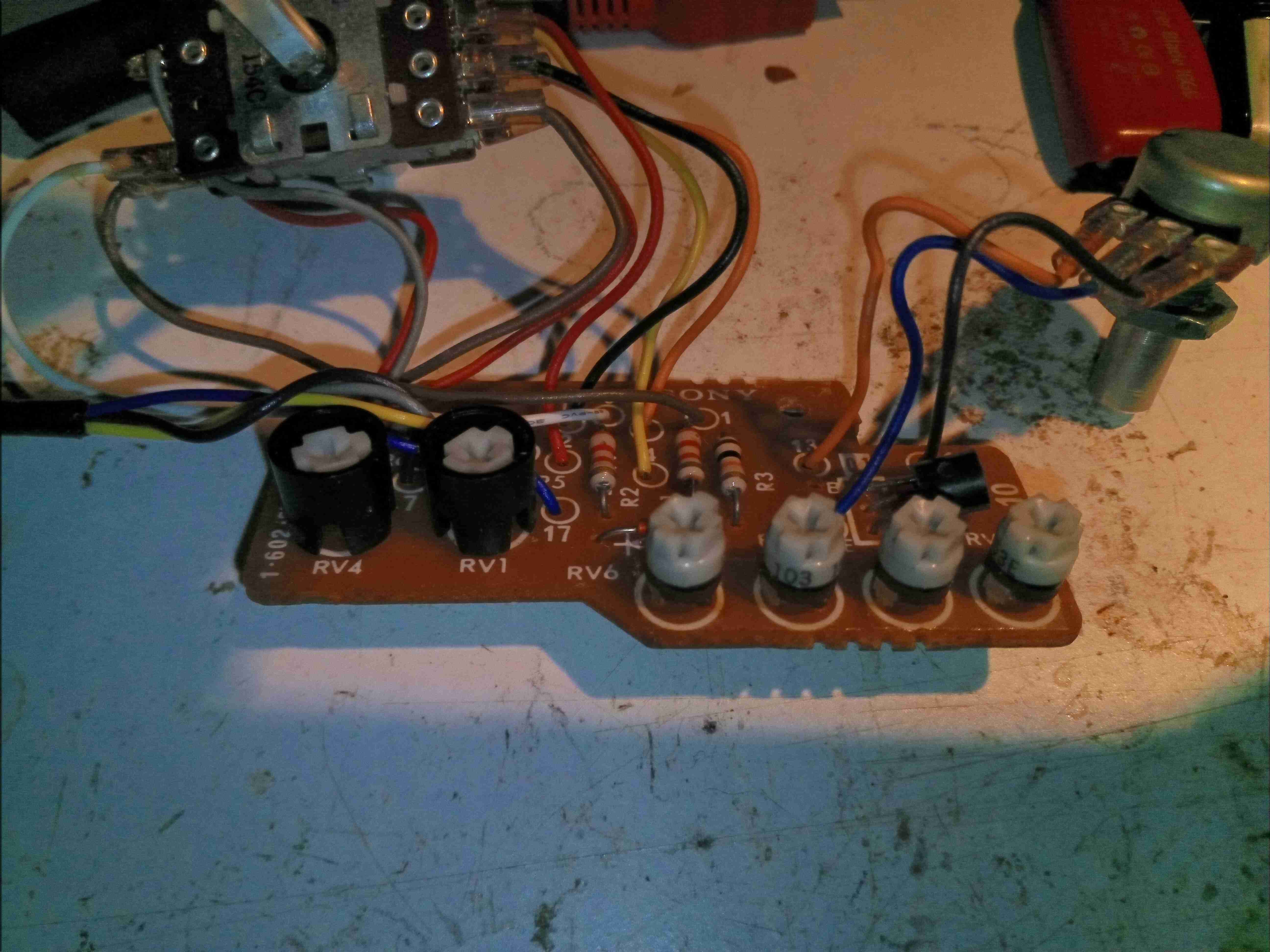
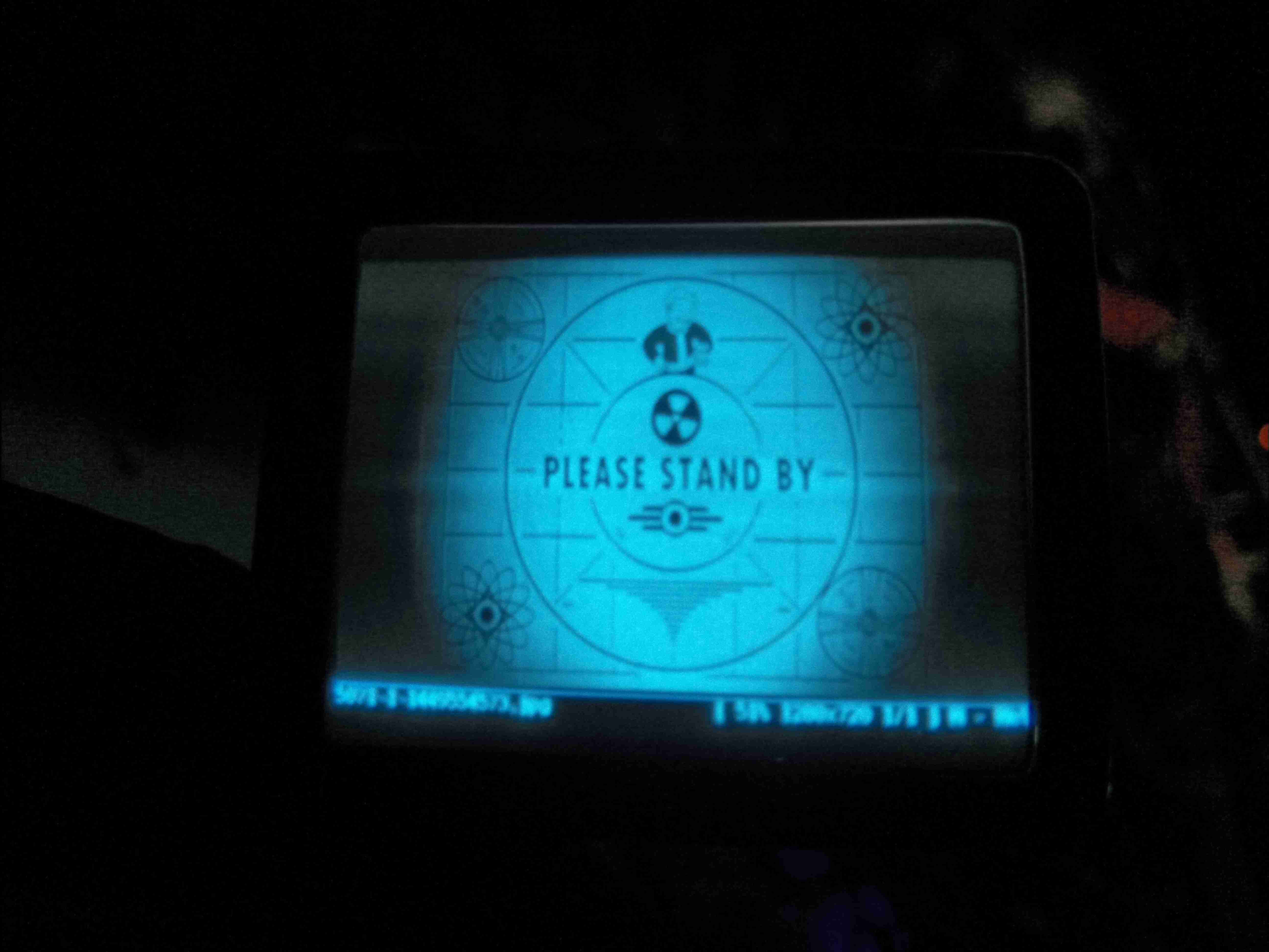
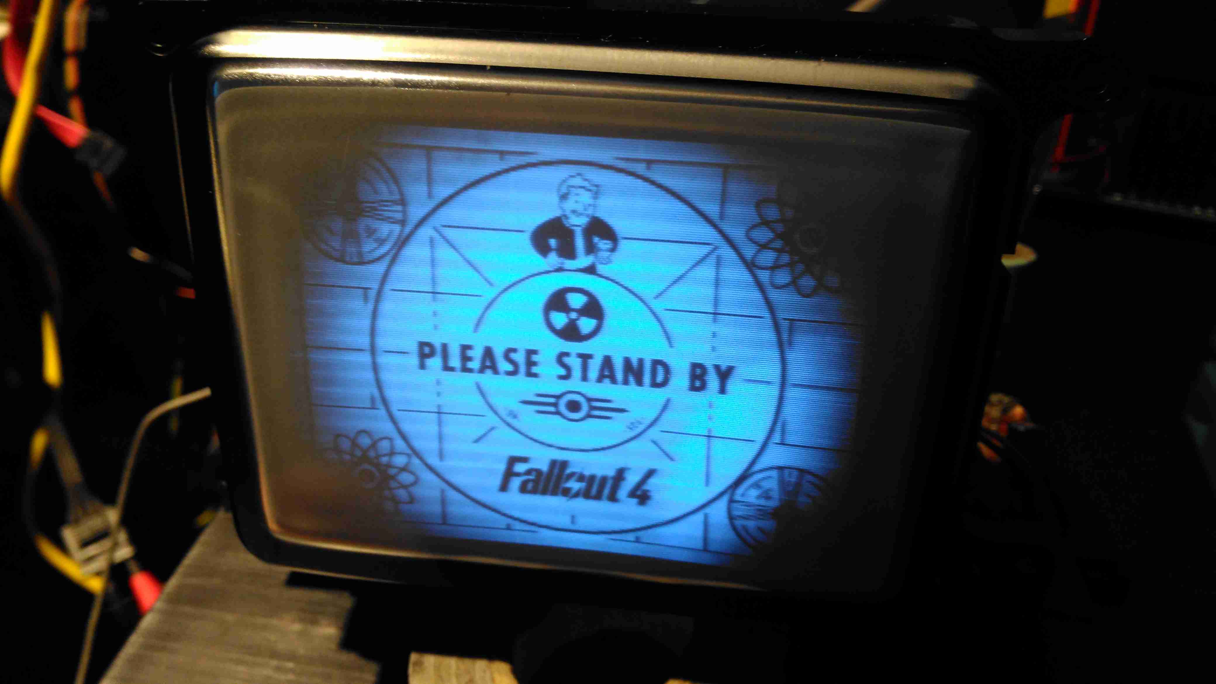
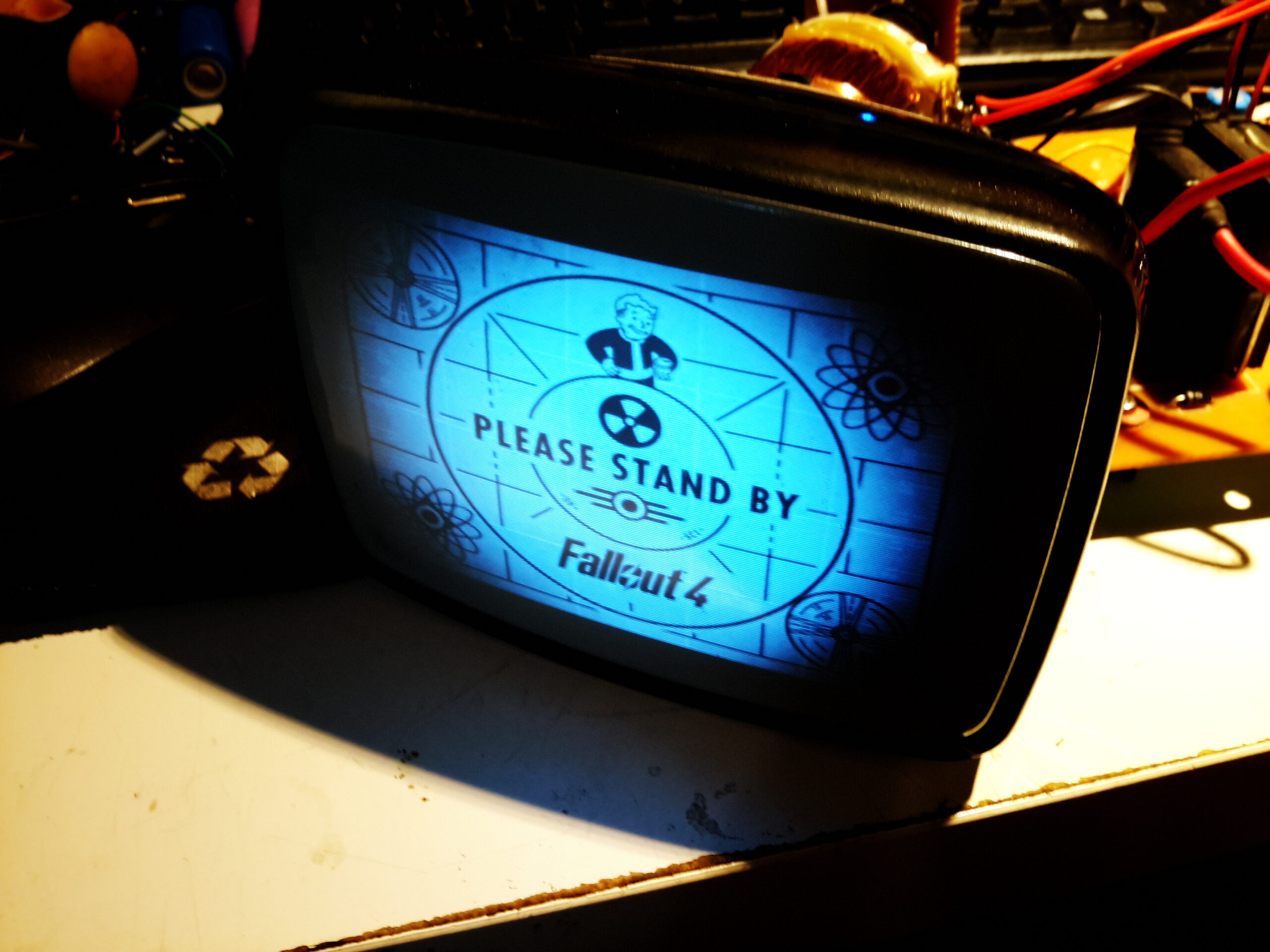
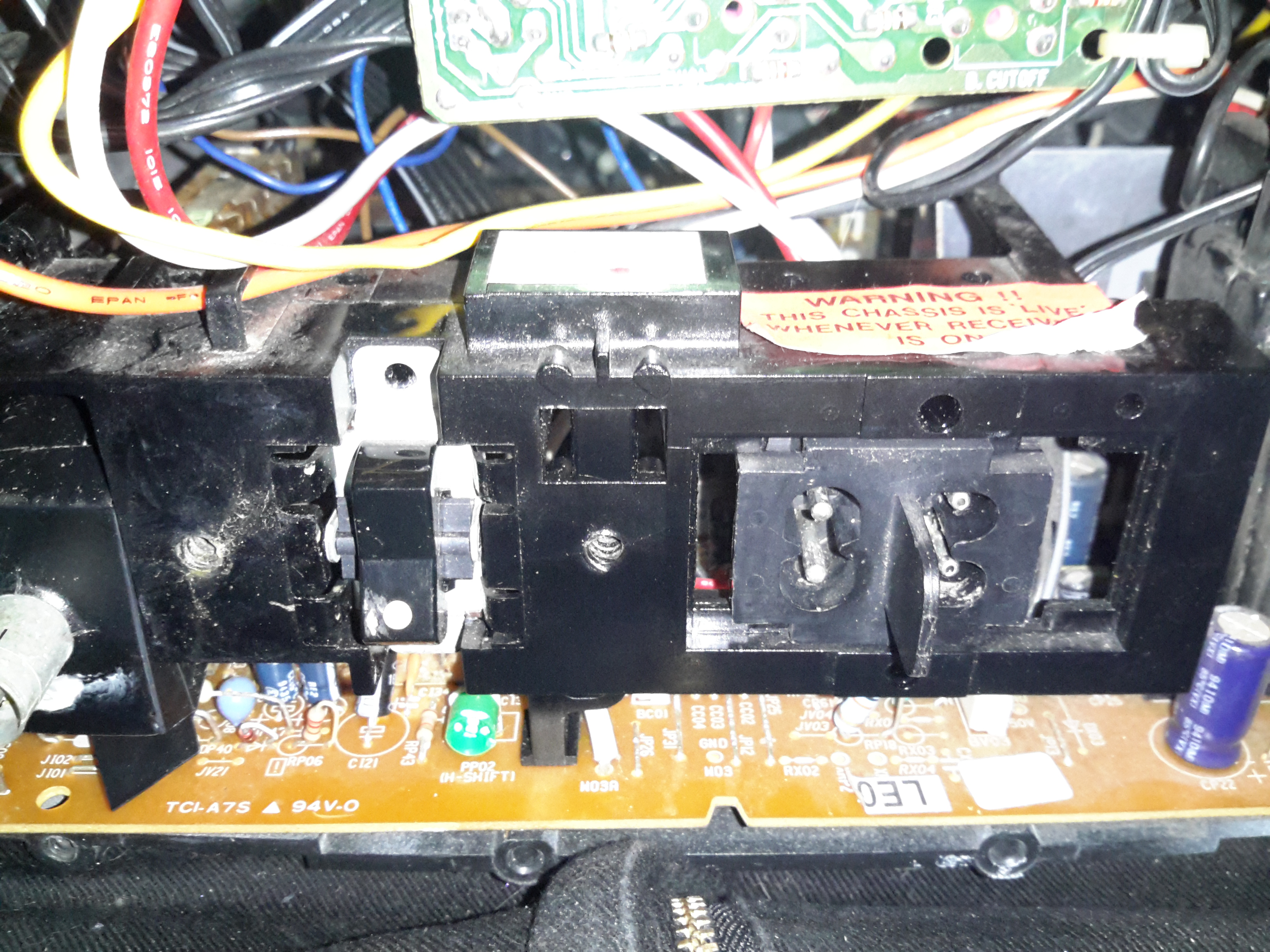
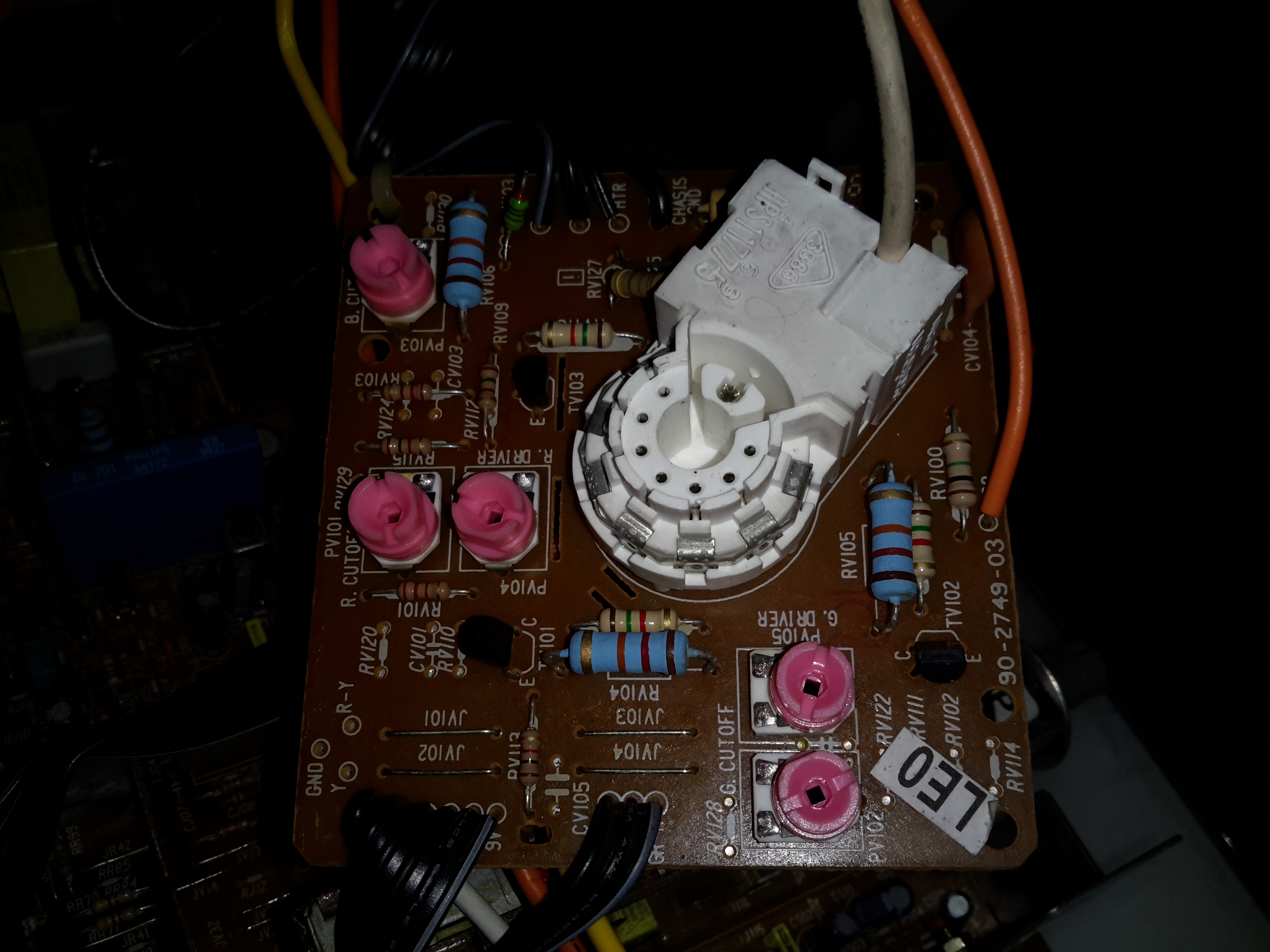
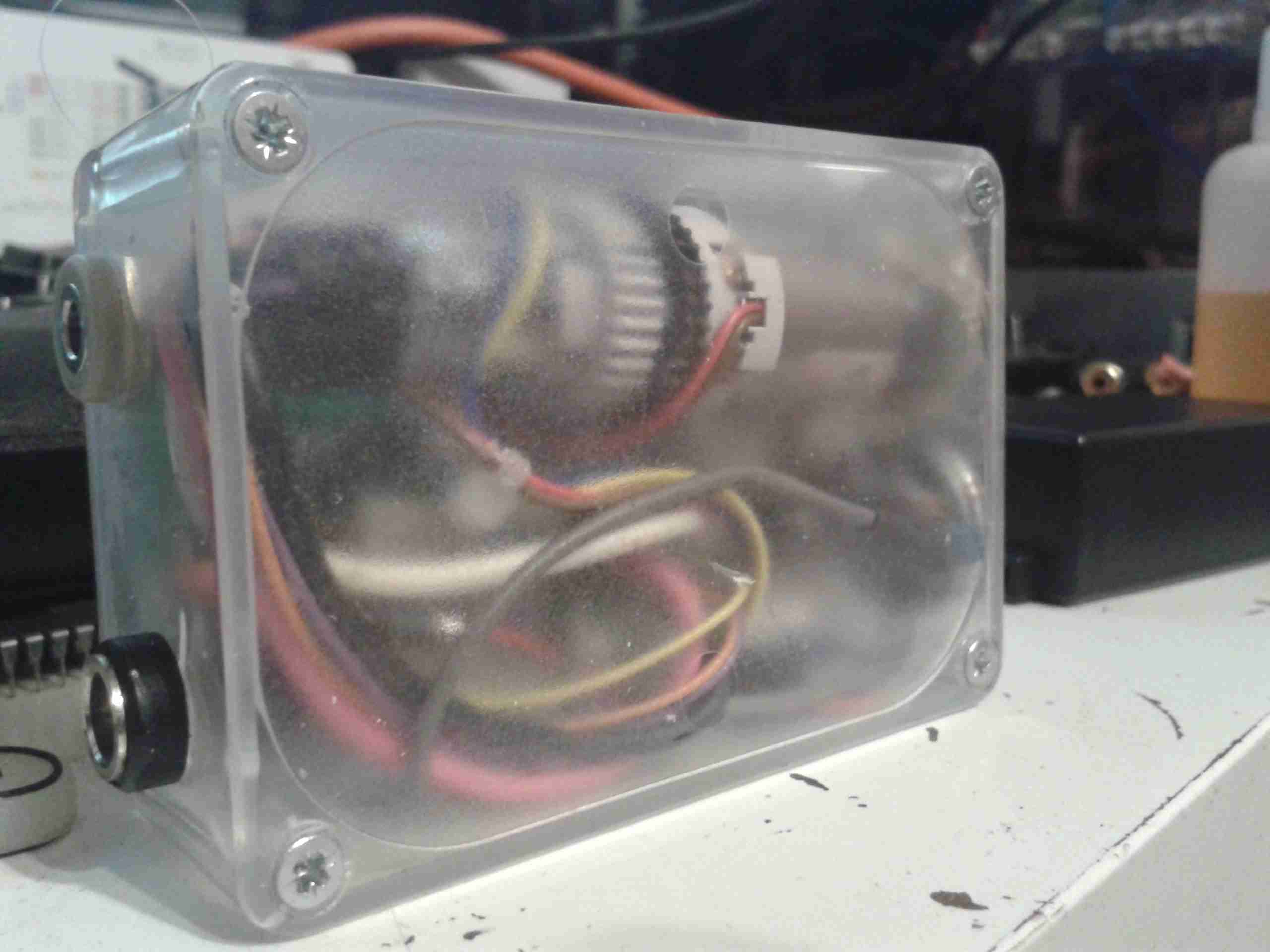
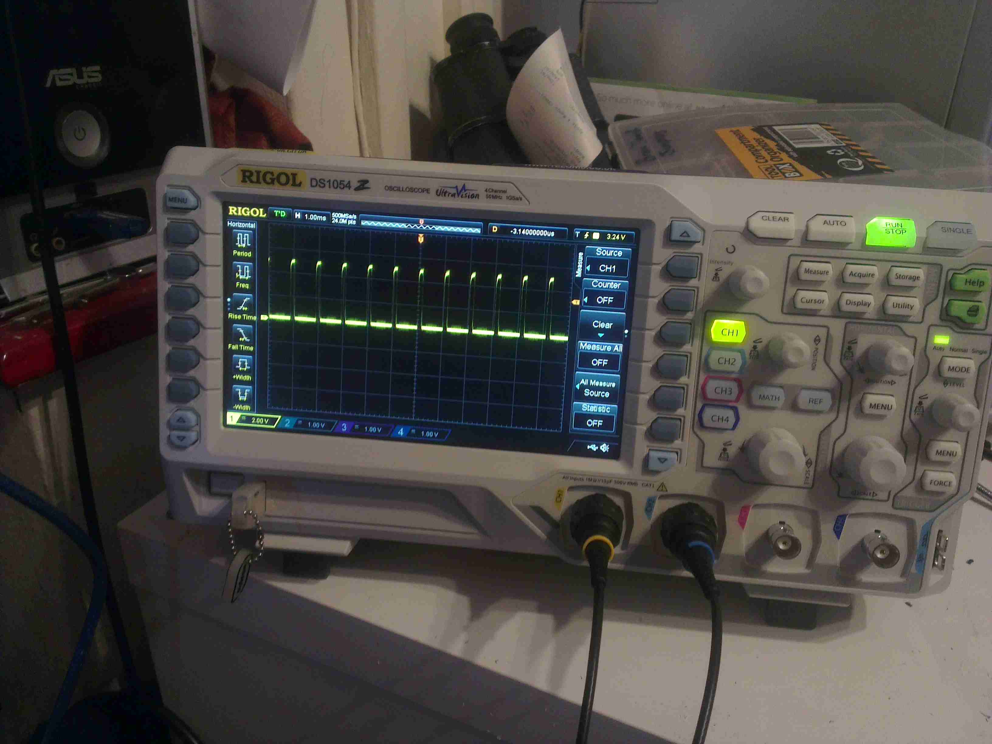
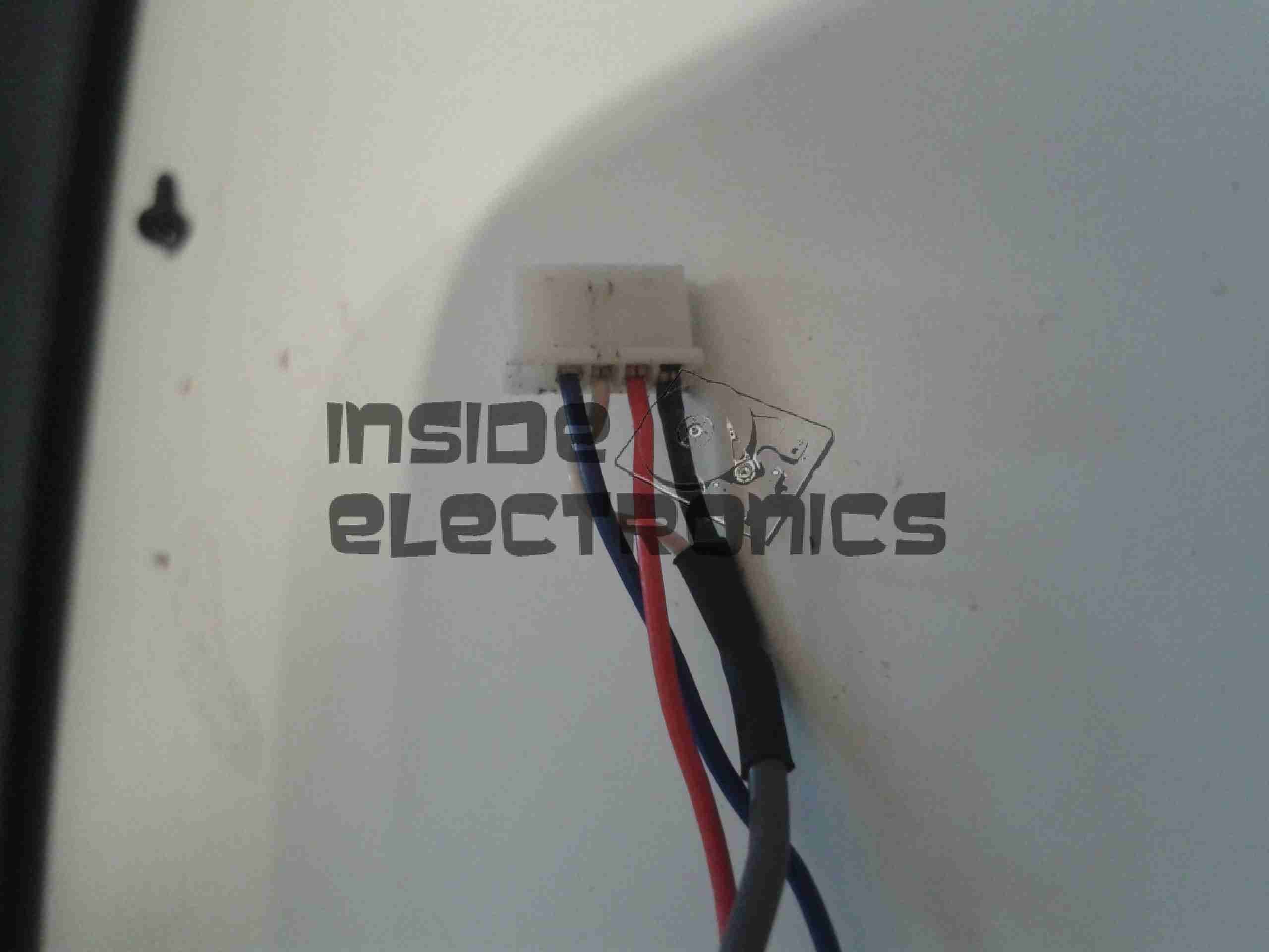
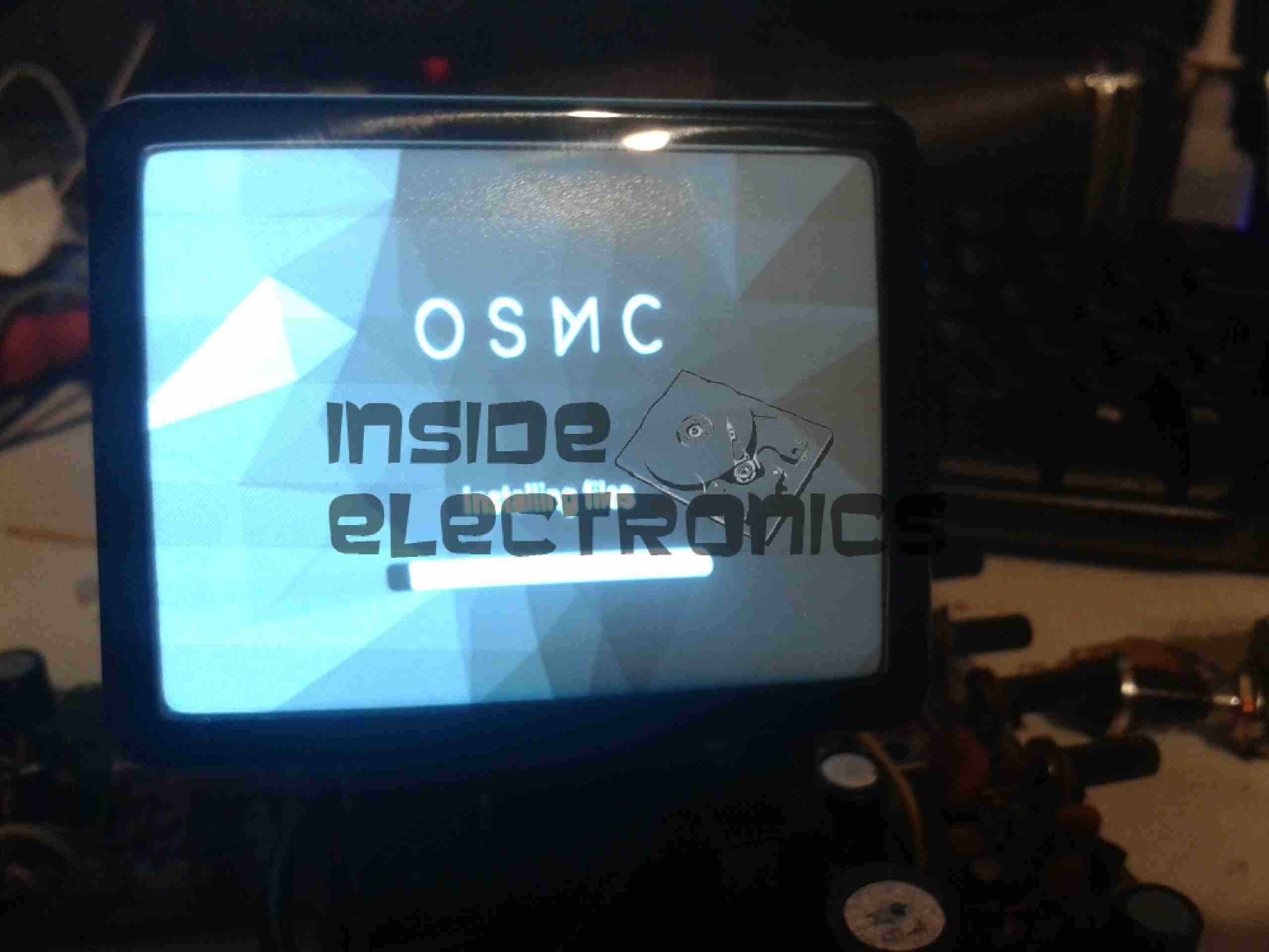
There’s a few adjustments available on this unit, here are the Focus & Horizontal Frequency (Hold) pots. Amazingly, even though this unit is about 43 years old at the time of writing, the unit fired straight up when I applied power & a composite video signal, with no adjustments required at all!

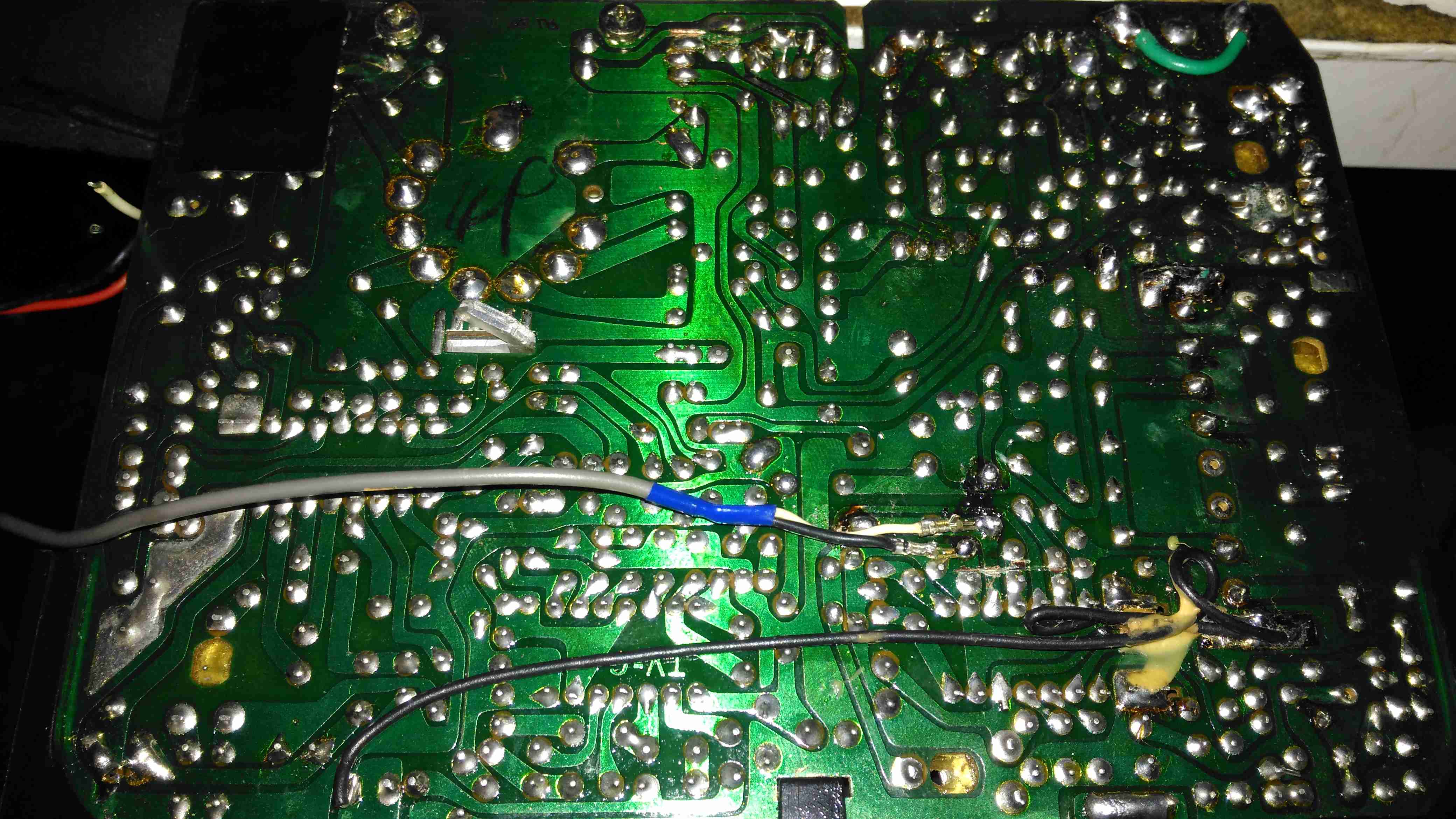
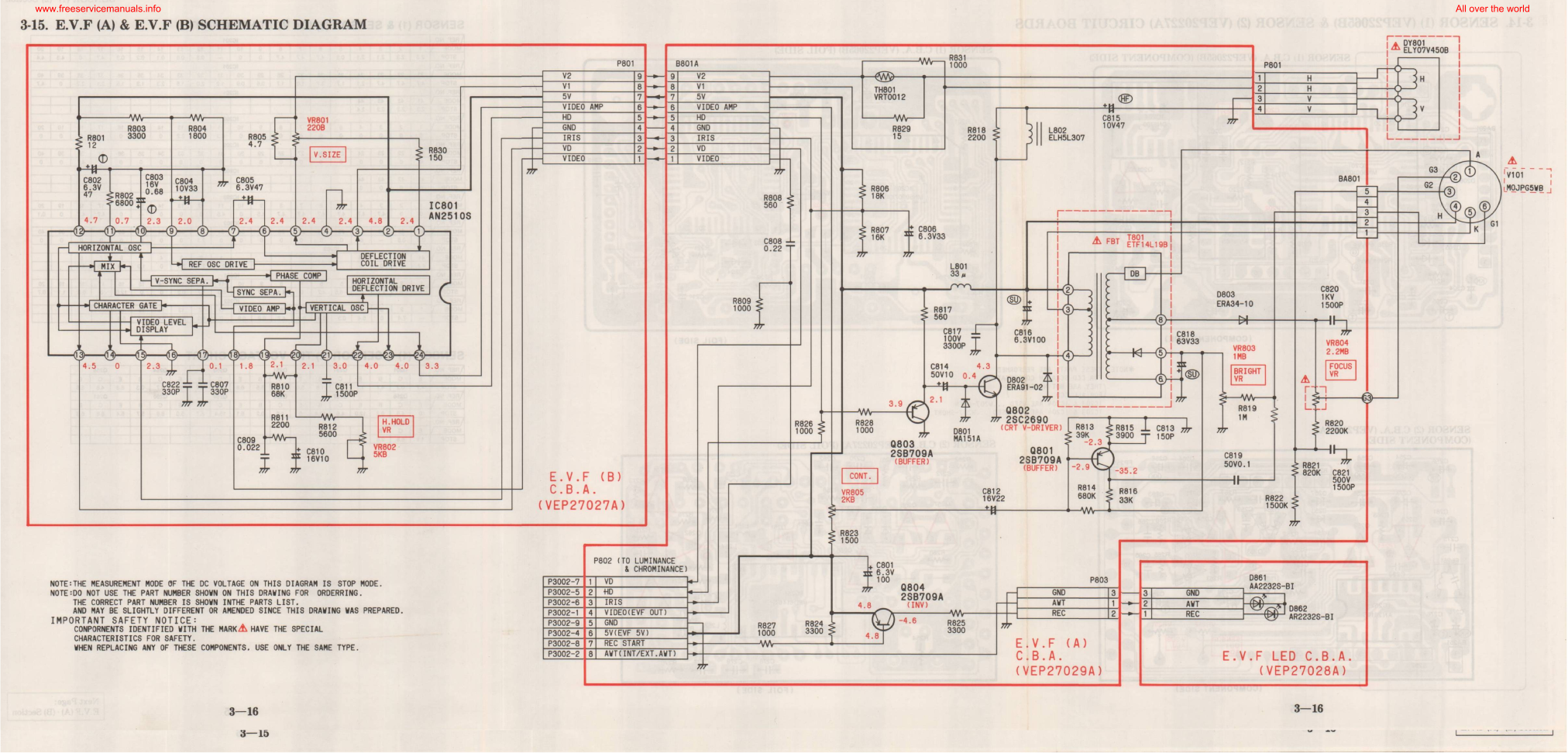
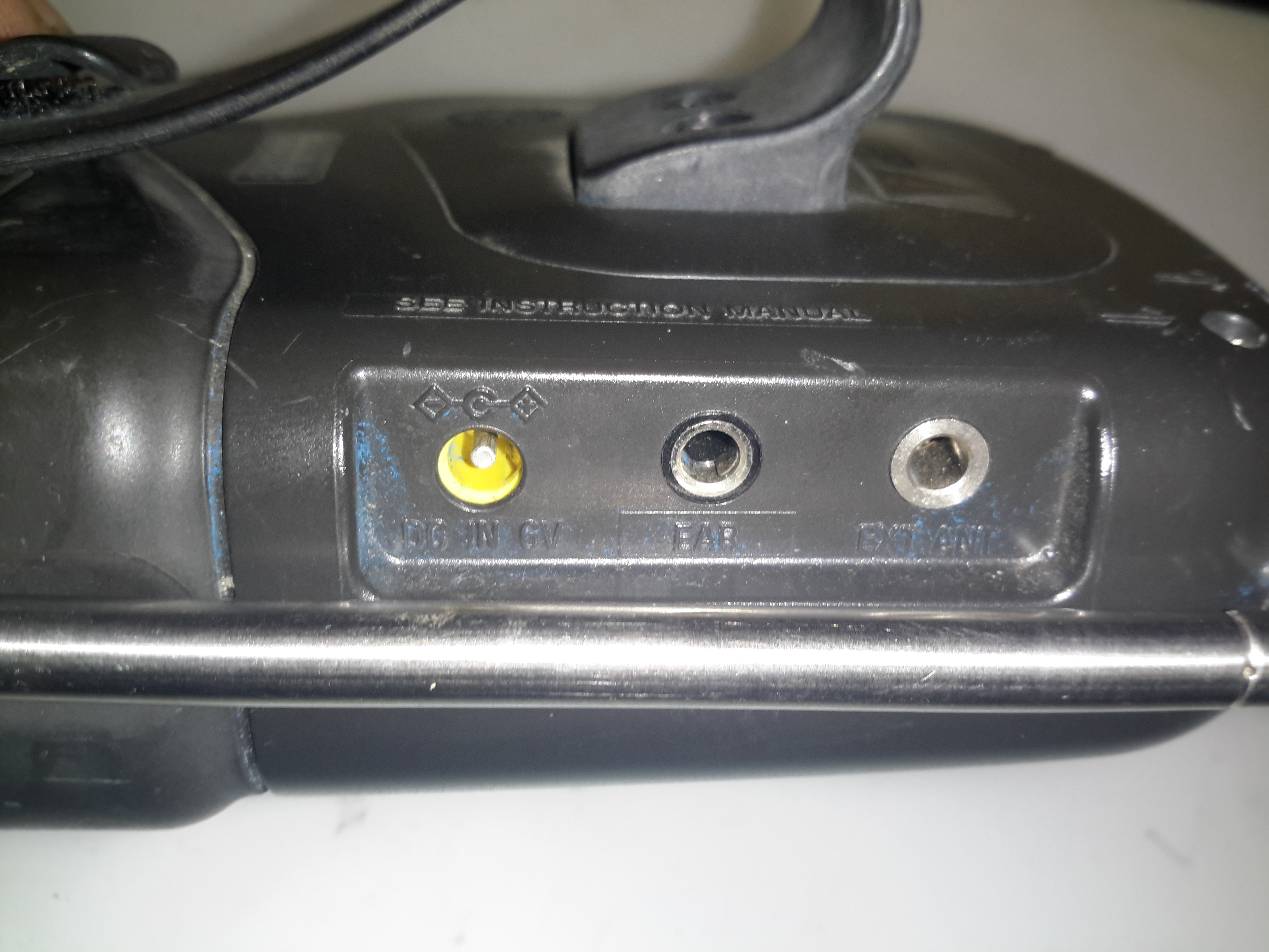
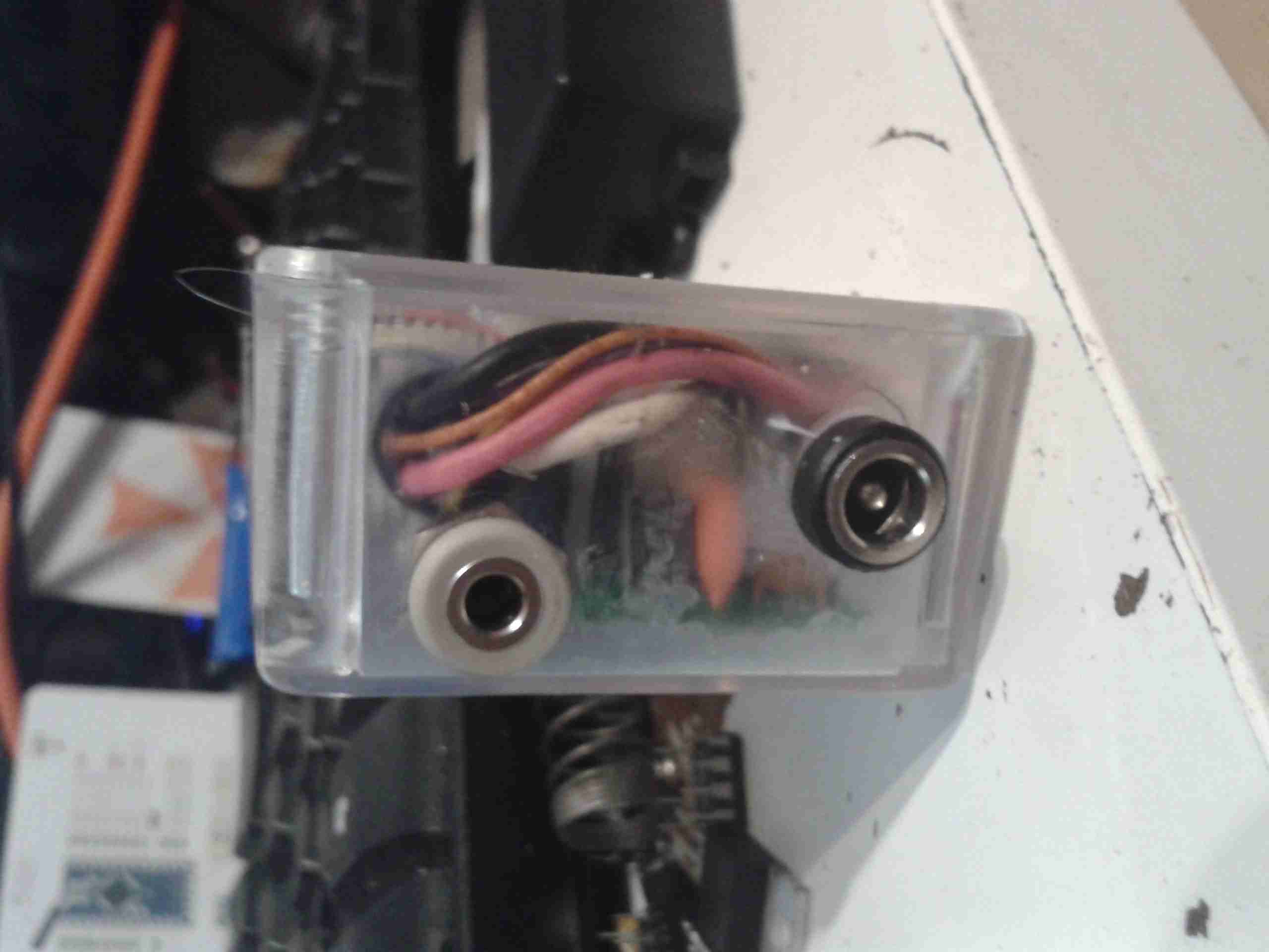
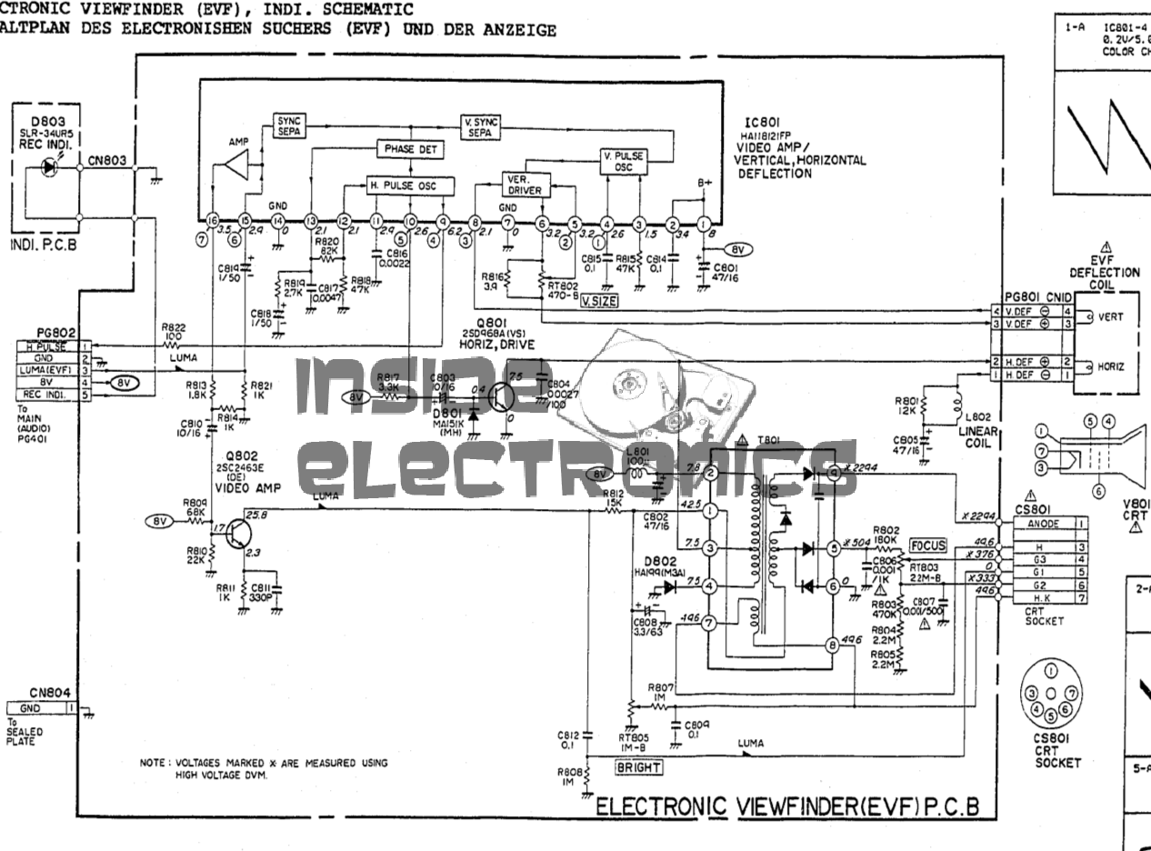
Unfortunately there’s no service manual or schematics that I could find on the web for this or the camera it came from, but connections to make this unit work are very simple:

Wire ColourSignal Name
YELLOW+12V DC
BLACKGND
Coax - CoreComposite Video 1v p-p
Coax - ShieldComposite Video GND

There’s another blogger who’s done this particular viewfinder, but they didn’t dig into the unit anywhere near as far as I usually do:

https://hex.ro/wp/blog/matsushita-40cb4-mini-crt/

This blog has a lot of CRT-based viewfinder teardowns, mainly from newer cameras. It’s an interesting read.

Datasheets for the important parts (the ones I could find!) below:


Posted on 10 Comments

Sony HVC-3000P Trinicon Camera Teardown

Camera Left
Camera Left

Following on from the viewfinder teardown, here’s the rest of the camera. This unit dates back to 1980, and is made almost exclusively of cast aluminium. Very little plastic has been used here & only for the bits that the user comes into contact with. This camera is based around the Sony Trinicon camera tube system, technology dating back before CCDs. There aren’t many controls on this side of the camera, only the record button, which is hidden behind the camera handgrip.

Camera Right
Camera Right

The other side of the camera has most of the controls for the picture.

Image Controls
Image Controls

The image controls inclue auto / manual iris, white balance & colour balance.

Rear Panel
Rear Panel

Sharpness & fader controls are on the back of the camera, along with the umbilical cable which would have connected to a Betamax recorder.

Main Lens
Main Lens

The lens on this camera is massive, at least a kilo of optical glass. Focus control is manual, with both auto & manual zoom control.

Lens Zoom Control
Lens Zoom Control

The Zoom controls are on top of the grip, with a button to the rear of the control which I have no idea about. The internal belts are a bit rotted with age so the zoom function doesn’t work great.

Trinicon Control Board

After removing the side covers, the two large PCBs become visible. These units are absolutely packed with electronics. On this side is the Trinicon tube control board, generating all the high voltages for electron beam acceleration, focus & electrostatic deflection of the beam. There’s around 500 volts knocking around on this board, with some rather specialised hybrid modules doing all the high voltage magic.

Video Process Board
Video Process Board

The other side of the camera has the video process board, which performs all the colour separation of the video signal from the tube, processes the resulting signals into a composite video signal, and finally sends it down the umbilical.

Bare Controls
Bare Controls

Removing some of the remaining covers exposes the bare video controls, and a small PCB just underneath covered in trimpots to set factory levels.

White Balance Filter Arm

The white balance is partially electronic & partially mechanical. This lever actuates a filter inside the lens assrembly.

Remote Connector
Remote Connector

A DIN connector offers remote control ability. The large loom of wires disappearing off to the right is dealing with the zoom mechanism & the onboard microphone amplifier. Just under the DIN connector hides the system power supply, inside a soldered can. The can under the white tape is the head end amplifier for the Trinicon video tube.

Trinicon Mount
Trinicon Mount

Hiding in the centre of the camera inside the casting is the Trinicon tube assembly itself. The label can just be seen here.

Camera Internals 1
Camera Internals 1

As is typical of 1980’s electronic design, the main boards swing down & are designed to slot into the base casting folded out for repairs. Internally the unit is a rat’s nest of wiring loom. There’s also another shielding can in here nestled between the boards – this is the video sync generator circuit.

Camera Internals 2
Camera Internals 2

The other side gives a better view of the video sync generator can. I’ll dive into the individual modules later on.

Lens Zoom Assembly
Lens Zoom Assembly

Under the remaining side cover is the zoom assembly & microphone amplifier board. More massive wiring loom hides within.

Video Sync Generator

The video sync generator is pretty sparse inside, just a large Sony CX773 Sync Generator IC, with a pair of crystals. There are a couple of adjustments in here for video sync frequencies.

Head End Amplifier
Head End Amplifier

Removed from it’s shielding can, here is the head end amplifier for the Trinicon tube. This very sensitive JFET input amplifier feeds into the main video process board.

Input Transformer
Input Transformer

The Trinicon tube target connects to this input transformer on the front of the amplifier board.

Internal Video Adjustments

The internal white balance controls are on this small PCB, mounted under the user-accessible controls.

Vidicon Control Board

Here’s the main control board responsible for the Trinicon tube & exposure control. Down near the front is the auto-iris circuit, nearer the centre is timing control & at the top is the high voltage power supply & deflection generator ICs.

High Voltage Section

Here’s the high voltage section, the main transformer at right generating the voltages required to drive the video tube. The large orange hybrids here are a pair of BX369 high-voltage sawtooth generators that create the deflection waveforms for the tube. The other large hybrid is a BX382 Fader Control.

Video Process Board
Video Process Board

The other large board contains all the video process circuitry, all analogue of course. There are a lot of manual adjustment pots on this board.

Lens Barrel
Lens Barrel

After removing the lens assembly, the tube assembly is visible inside the barrel casting. Not much to see yet, just the IR filter assembly.

Trinicon Tube Assembly

Here’s the unit removed from the camera. Unfortunately this tube is dead – it shows a lot of target burn on the resulting image, and very bad ghosting on what poor image there is. The Trinicon tube itself is encased in the focus coil assembly, the windings of which are hidden under the shielding.

IR Filter
IR Filter

The IR filter is locked into the front of the tube, on a bayonet fitting. The twin target wires are running off to the left, where they would connect to the head end amplifier.

Bare Tube
Bare Tube

After removing the IR filter glass, the Trinicon tube itself is removed from the focus coil assembly. There’s an electron gun at the rear of the tube, like all CRTs, although this one works in reverse – sensing an image projected on the front instead of generating one.

Deflection Plates
Deflection Plates

It’s a little difficult to see, but the electrostatic deflection electrodes in this tube are created from the aluminium flashing on the inside of the glass, in a zig-zag pattern. The interleaving electrodes are connected to base pins by spring contacts at the electron gun end of the tube.

Electron Gun
Electron Gun

The electron gun is mostly hidden by the getter flash & the deflection electrodes, but the cathode can is visible through the glass, along with the spring contacts that make a connection to the deflection electrodes. This is also a very short gun – it doesn’t extend more than about 5mm into the deflection zone. The rest of the tube up to the target is empty space.

Target
Target

Finally, here’s the target end of the tube. I’m not sure how the wires are attached to the terminals – it certainly isn’t solder, maybe conductive adhesive?
It uses a vertically striped RGB colour filter over the faceplate of an otherwise standard Vidicon imaging tube to segment the scan into corresponding red, green and blue segments. It is used mostly in low-end consumer cameras, though Sony also used it in some moderate cost professional cameras in the 1980s.
Although the idea of using colour stripe filters over the target was not new, the Trinicon was the only tube to use the primary RGB colours. This necessitated an additional electrode buried in the target to detect where the scanning electron beam was relative to the stripe filter. Previous colour stripe systems had used colours where the colour circuitry was able to separate the colours purely from the relative amplitudes of the signals. As a result, the Trinicon featured a larger dynamic range of operation.

I have the service manuals below for the HVP-2000P & the HVP-4000P, which are very similar cameras, so these may be useful to anyone who has one of these!


Posted on 2 Comments

Sony HVF-2000P Viewfinder Teardown & Composite Video Hack

Rating Plate
Rating Plate

Well, it’s time for another viewfinder hack! I’ve been after one of these for a while, this is from an early 1980’s era Sony Trinicon camera, and instead of the tiny ½” round CRT display, these have a 1.5″ square CRT – a Matsushita 40CB4. Luckily I managed to score a pair of these from eBay for very little money. Update: The second camera’s viewfinder module turned out to have a dead flyback transformer, but at least I have a good spare CRT & the rest of the support components. More to come later on the teardown of the camera itself.

Mirror & Eyecup Assembly

The eyecup assembly with the magnifying lens & turning mirror is easy to remove, with clips & a single screw holding it onto the CRT holder sticking out of the side of the main casing.

Top Cover Removed
Top Cover Removed

Removing some screws around the case allows the top cover to be removed, revealing the electronics. There’s certainly more in here than the later camera viewfinders, in this unit there are two boards slotted together with a board-to-board interconnect at the bottom. The CRT is at the top of the photo, hiding inside the plastic housing & deflection yoke assembly.

Bare PCBs & CRT
Bare PCBs & CRT

Here’s the CRT & one of the control boards removed from the case, having been stripped of the heatshrink tube that held the final anode lead in place. Just like on larger CRTs, this viewfinder has the final anode on a cavity connector fused into the bell, instead of being led out to a pin on the base. This is probably due to the much higher anode voltage of 5kV, a big jump from the 2kV on the ½” round tubes.

40CB4 CRT Label
40CB4 CRT Label

Yup, it’s definitely the elusive 40CB4. Apparently these CRTs are still manufactured to this day for professional camera viewfinders, as the resolution of this small vacuum tube is still better than similarly sized modern tech such as LCDs or OLEDs. The phosphor used is type P4 – ZnS:Ag+(Zn,Cd)S:Ag, with an aluminized overcoat.

Bare 40CB4 CRT
Bare 40CB4 CRT

After the base connector & deflection yoke are removed from the tube, the very long neck can be seen, this long glass neck apparently giving better focus & resolution than the stubbier tubes.

Electron Gun
Electron Gun

The electron gun is the usual single unit as usually found in monochrome tubes.

Deflection Board
Deflection Board

The bottom board in the assembly has all the control circuitry for the CRT, including the HA11244 deflection IC, composite sync separator & vertical deflection drive circuit. There are also circuits here to display a video waveform on the CRT, along with iris & white balance markers.

Horizontal Board
Horizontal Board

The other board has the horizontal drive circuitry, along with the video input amplifier. Despite the attempt to miniaturize the entire assembly, these are still well packed boards. Some of the resistors & diodes are bussed together in custom SIL hybrid modules to save PCB space. Like all the other CRT viewfinders, these units are meant for viewing via a mirror – the horizontal deflection coil connections need to be reversed to show a correct image without the mirror. The Red & Blue wires to the yoke need to be swapped here.

Flyback Transformer
Flyback Transformer

The horizontal board on this unit also supports the flyback transformer, which is massive compared to the other viewfinder circuits. Biasing, focus & filament supplies for the CRT are also derived from this transformer, via auxiliary windings.

Boards Connected
Boards Connected

The boards slot together in the centre to form the fully operational circuit.

Video Input
Video Input

Out of the 3 plugs emerging from the cable feeding the viiewfinder, only this one is important, on the horizontal drive board. Black is ground, Brown +8.5v & red is composite video input. There’s also a resistor tied into the positive rail to the video input pin, which pulls it high to 8.5v – this is R1 right next to this connector. Desolder this 22K resistor to help protect anything feeding a signal into the unit, like a RPi, it’s not needed for normal operation.

Fallout!
Fallout!

As usual for a CRT post, the Fallout loading screen on the display. The picture quality isn’t as good as it should be, probably due to the noisy buck-converter I have rigged up for testing. If it doesn’t get better with a linear regulator, I’ll start replacing the 39 year old electrolytic capacitors. Current draw is 130mA at 7.5v. Schematics for this unit & the CRT datasheet are available below:


Posted on 2 Comments

Goodmans Quadro 902 Composite Video Mod

CRT Module
CRT Module

Here’s the CRT & it’s drive board removed from the main chassis. Nicely modular this unit, all the individual modules (radio, tape, TV), are separate. This is effectively a TV itself, all the tuner & IF section are onboard, unlike in other vintage units I’ve modified, where the tuner & IF has been on a separate board. There’s a 3-pin header bottom centre for the tuning potentiometer, and external antenna input jack. The internal coax for the built in antenna has been desoldered from the board here. here a the usual controls on the back for adjusting brightness, contrast & V Hold, all the other adjustments are trimmers on the PCB.
Unfortunately after 30+ years of storage, this didn’t work on first power up, neither of the oscillators for vertical or horizontal deflection would lock onto the incoming signal, but a couple of hours running seemed to improve things greatly. The numerous electrolytic capacitors in this unit were probably in need of some reforming after all this time, although out of all of them, only 21 are anything to do with the CRT itself.

Anode Cap
Anode Cap

Here’s the anode side of the unit, with the small flyback transformer. The rubber anode cap has become very hard with age, so I’ll replace this with a decent silicone one from another dead TV. The Horizontal Output Transistor (a 2SC2233 NPN type) & linearity coil are visible at the bottom right corner of the board. Unfortunately, the disgusting yellow glue has been used to secure some of the wiring & large electrolytics, this stuff tends to turn brown with age & become conductive, so it has to be removed. Doing this is a bit of a pain though. It’s still a little bit flexible in places, and rock hard in others. Soaking in acetone softens it up a little & makes it easier to detach from the components.

Neck PCB
Neck PCB

There’s little on the neck board apart from a few resistors, forming the limiting components for the video signal, and the focus divider of 1MΩ & 470KΩ feeding G3. No adjustable focus on this unit. There’s also a spark gap between the cathode line & ground, to limit the filament to cathode voltage. The flyback transformer is nestled into the heatsink used by the horizontal output transistor & a voltage regulator transistor.

Tube Details
Tube Details

The CRT is a Samsung Electron Devices 4ADC4, with a really wide deflection angle. It’s a fair bit shorter than the Chinese CRT I have which is just a little larger, with a neck tube very thin indeed for the overall tube size.
Unusually, while the filament voltage is derived from the flyback transformer as usual, it’s rectified into DC in this unit, passing through a 1Ω resistor before the filament connection. I measured 5.3v here. The glow from the filament is barely visible even in the dark.

Electron Gun 1
Electron Gun 1

The electron gun is the usual for a monochrome tube, with 7 pins on the seal end.

Electron Gun 2
Electron Gun 2

The electrodes here from left are Final Anode, G3 (Focus Grid), Accelerating Anode, G2 (Screen Grid), G1 (Control Grid). The cathode & filament are hidden inside G1. In operation there’s about 250v on G2, and about 80v on G3.

Chipset
Chipset

The chipset used here is all NEC, starting with a µPC1366C Video IF Processor, which receives the IF signal from the tuner module to the left. This IC outputs the standard composite signal, and a modulated sound signal.
This then splits off to a µPC1382C Sound IF Processor & Attenuator IC, which feeds the resulting sound through the two pin header at the right bottom edge of the board to the audio amplifier in the chassis.
The composite video signal is fed through a discrete video amplifier with a single 2SC2229 transistor before going to the CRT cathode.
The remaining IC is a µPC1379C Sync Signal Processor, containing the sync separator, this is generating the required waveforms to drive the CRT deflection systems from another tap off the composite video line.
From this chip I can assume the unit was built around 1986, since this is the only date code on any of the semiconductors. Besides these 3 ICs, the rest of the circuit is all discrete components, which are well-crammed into the small board space.
There are 5 trimmer potentiometers on the board here, I’ve managed to work out the functions of nearly all of them:

  • SVR1: IF Gain Adjust
  • SVR2: H. Hold
  • SVR3: V. Size
  • SVR4: B+ Voltage Adjust
  • SVR5: Tuner Frequency Alignment? It’s in series with the tuning potentiometer in the chassis.
PCB Bottom
PCB Bottom

The PCB bottom shows the curved track layout typical of a hand taped out board. The soldermask is starting to flake off in places due to age, and there a couple of bodge wires completing a few ground traces. Respinning a board in those days was an expensive deal! Surprisingly, after all this time I’ve found no significant drift in the fixed resistors, but the carbon track potentiometers are drifiting significantly – 10KΩ pots are measuring as low as 8KΩ out of circuit. These will have to be replaced with modern versions, since there are a couple in timing-sensitive places, like the vertical & horizontal oscillator circuits.

Anode Cap Replaced
Anode Cap Replaced

Here the anode cap has been replaced with a better silicone one from another TV. This should help keep the 6kV on the CRT from making an escape. This was an easy fix – pulling the contact fork out of the cap with it’s HT lead, desoldering the fork & refitting with the new cap in place.

Here I’ve replaced the important trimmers with new ones. Should help stabilize things a little.

Composite Injection Mod

Injecting a video signal is as easy as the other units. Pin 3 of the µPC1366C Video IF Processor is it’s output, so the track to Pin 3 is cut and a coax is soldered into place to feed in an external signal.

CRT In Operation
CRT In Operation

After hooking up a Raspberry Pi, we have display! Not bad after having stood idle for 30+ years.

Datasheets for the important ICs are available below:
[download id=”5690″]
[download id=”5693″]
[download id=”5696″]

Posted on 2 Comments

STVG-502 Karaoke Machine CRT

Image Display

Here’s the CRT circuitry from a tossed STVG-502 Karaoke Machine, which got a good soaking in Manchester’s brilliantly wet weather before I managed to get hold of it:

Main PCB
Main PCB

I didn’t do a full teardown of this unit, since it was soaking wet & smelled rather badly of sour milk, so instead I quickly gutted it for the useful parts. These machines are a combination of a CD+G player, CRT composite monitor for displaying the CD+G lyrics & a small audio amplifier & 3W speaker. Power is provided from the mains via a transformer, with both 12 & 24v windings. One half of the board has the audio amplifier sections, the other the CRT drive, running from the 12v & 24v supplies respectively. I chopped off the audio section, as that wasn’t needed.

Linear Regulator
Linear Regulator

On this huge heatsink is what I originally thought was the horizontal drive transistor is actually a 12v linear regulator – the board gets fed 16v AC. This is then run through a rectifier which will produce an approx 22v rail, and after the smaller transistor on the left used for power switching. The 22v then gets dropped through a 1/2W 1Ω resistor, then the linear regulator drops it down to 12v for the rest of the circuit – dissipating a goodly amount of power in the process.

Horizontal Output Transistor

This is in fact the horizontal drive transistor, a 2SD613, which according to the datasheet, is intended for audio amplifier output stage applications, not CRT drive. Regardless, it’s an 85v 6A NPN transistor, and does get a bit on the warm side, but was never given a heatsink from the factory.

CRT Drive IC
CRT Drive IC

All the drive signals for the CRT are taken care of by this single DIP IC – a CD1379CP from Silicore. Considering the older CRT-based devices I have, with entire boards twice the size of this one dedicated to discrete components required to drive a CRT, this is definitely an advance in technology. Very few external components are being used, and no custom magnetics.

Video Input
Video Input

The video signal comes in from the CD+G player module on this connector, it’s a standard composite input. The composite video is fed into an amplifier after the controller IC. This video amp is powered from a 140v rail from the flyback transformer, to give enough signal to drive the CRT cathode.

LOPT
LOPT

The high voltage transformer is a BSH8-N5513L, I’ve not been able to find any data on this, but it looks like a standard off the shelf transformer from the listings on the Chinese supplier sites. There are very few support components around here, just a couple of diodes to rectify the high voltage focus supply, and no linearity coil. Weirdly, the 1st accelerating anode of the tube is grounded in this circuit. Very few adjustments are provided, most are set with fixed resistors to keep the cost low.

The CRT

14SX3Y4 CRT
14SX3Y4 CRT

Here’s the CRT, it’s a 5″ monochrome model. I’ve not been able to find much data on this either.

Bent Electron Gun
Bent Electron Gun

Seems the gents in the Shenzhen factory were having a bit of an off day when this one was made – the electron gun assembly is actually tilted in the neck of the tube – as a result the spot formed with no deflection is far from the centre of the screen. This tube does still produce a pretty good picture though, this manufacturing error is easily corrected for with the positioning magnets on the deflection yoke.

Final Mods

PCB Mods
PCB Mods

I’ve installed a couple of mod wires on the bottom of the PCB to get this to work outside the original application, without the room heater of a linear regulator in circuit this will run fine from a 12v supply. The PCB quality is a bit naff – even quick heating with a soldering iron makes tracks fall off the laminated paper board.

Image Display
Image Display

Image quality is surprisingly good for the cheapest CRT-based monitor I’ve ever seen, I figured a Fallout reference was required here; anyone for a proper CRT-based PipBoy? 😉 Shame the phosphor isn’t green.

Posted on 2 Comments

Ferguson A10RWH Portable Colour TV Teardown

Back Removed
Back Removed

Here’s the other TV that was picked up from the local water point having been put of to be recycled. This one is much newer than the Thorn TV, a 10″ colour version from Ferguson.

RCA 27GDC85X CRT
RCA 27GDC85X CRT

The colour CRT used is an RCA branded one, 27GDC85X.

Power Inputs
Power Inputs

Like the other TV, this one is dual voltage input, mains 240v & 12v battery. This TV is a factory conversion of a standard 240v AC chassis though.

HV PSU
HV PSU

The 12v power first goes into this board, which looked suspiciously like an inverter. Measuring on the output pins confirmed I was right, this addon board generates a 330v DC supply under a load, but it’s not regulated at all, under no load the output voltage shoots up to nearly 600v!

Live Chassis
Live Chassis

I’ve not seen one of these labels on a TV for many years, when back in the very old TV sets the steel chassis would be used to supply power to parts of the circuitry, to save on copper. Although it doesn’t have a metal chassis to actually become live, so I’m not sure why it’s here.

Main PCB
Main PCB

The main PCB is much more integrated in this newer TV, from the mid 90’s, everything is pretty much taken care of by silicon by this point.

Main Microcontroller

This Toshiba µC takes care of channel switching & displaying information on the CRT. The tuner in this TV is electronically controlled.

PAL Signal Processor

The video signal is handled by this Mitsubishi IC, which is a PAL Signal Processor, this does Video IF, Audio IF, Chroma, & generates the deflection oscillators & waveforms to drive the yoke.

CRT Adjustments
CRT Adjustments

There are some adjustments on the CRT neck board for RGB drive levels & cutoff levels. This board also had the final video amplifiers onboard, which drive the CRT cathodes.

Posted on 1 Comment

Panasonic NV-M5 CRT Viewfinder Hack

Viewfinder Circuits
Viewfinder Circuits


The old Panasonic NV-M5 has the standard for the time CRT based viewfinder assembly, which will happily take a composite video signal from an external source.

This viewfinder has many more connections than I would have expected, as it has an input for the iris signal, which places a movable marker on the edge of the display. This unit also has a pair of outputs for the vertical & horizontal deflection signals, I imagine for sync, but I’ve never seen these signals as an output on a viewfinder before.

EVF Schematic
EVF Schematic

Luckily I managed to get a service manual for the camera with a full schematic.
This unit takes a 5v input, as opposed to the 8-12v inputs on previous cameras, so watch out for this! There’s also no reverse polarity protection either.

Pins
Pins

Making the iris marker vanish from the screen is easy, just put a solder bridge between pins 15 & 16 of the drive IC. The important pins on the interface connector are as follows:

Pin 3: GND
Pin 4: Video Input
Pin 5: Video GND
Pins 6: +5v Supply

Posted on 12 Comments

Panasonic NV-M5 VHS Camcorder Teardown

Overview

Panasonic NV-M5 Camera

Time foe some more retro tech! This is a 1980’s vintage CCD-based VHS camcorder from Panasonic, the NV-M5. There are a lot of parts to one of these (unlike modern cameras), so I’ll split this post into several sections to make things easier to read (and easier to keep track of what I’m talking about :)).

Left Side
Left Side

The left side of the camera holds the autofocus, white balance, shutter speed & date controls.

Left Side Controls
Left Side Controls
Lens Adjustments
Lens Adjustments

The lens is fully adjustable, with either manual or motorized automatic control.

Rear Panel
Rear Panel

The back panel has the battery slot, a very strange looking DC input connector, remote control connector & the earphone jack.

Top Controls
Top Controls

The top panel of the camera holds the main power controls, manual tape tracking & the tape transport control panel.

Viewfinder
Viewfinder

The viewfinder is mounted on a swivel mount. There’s a CRT based composite monitor in here. Hack ahoy!

Camera Section

Process Board Assembly

Here’s the camera section of the camcorder, and is totally packed with electronics! There’s at least half a dozen separate boards in here, all fitted together around the optics tube assembly.

AWB PCB
AWB PCB

On the top of the assembly is the Automatic White Balance PCB. Many adjustments here to get everything set right. Not much on the other side of this board other than a bunch of Op-Amps. The iris stepper motor is fitted in a milled opening in the PCB, this connects to one of the other PCBs in the camera module.

AWB Sensor
AWB Sensor

Here’s the AWB sensor, mounted next to the lens. I’m not all to certain how this works, but the service manual has the pinout, and there are outputs for all the colour channels, RGB. So it’s probably a trio of photodiodes with filters.

Focus & Zoom Motors
Focus & Zoom Motors

Focus & Zoom are controlled with a pair of DC gear motors. The manual operation is feasible through the use of slip clutches in the final drive pinion onto the lens barrel.

Process Board
Process Board

The main camera section process board is above. This board does all the signal processing for the CCD, has the bias voltage supplies and houses the control sections for the motorized parts of the optics assembly. There are quite a few dipped Tantalum capacitors on pigtails, instead of being directly board mounted. This was probably done due to space requirements on the PCB itself.2016-08-20_13-40-11_000357

Under the steel shield on this board is some of the main signal processing for the CCD.

Optics Assembly
Optics Assembly

The back of the optics tube is a heavy casting, to supress vibration. This will be more clear later on.

Position Sensor Flex

The position of the lens elements is determined by reflective strips on the barrel & sensors on this flex PCB.

Sub Process Board
Sub Process Board

There’s another small board tucked into the side of the tube, this hooks into the process PCB.

Process Delay Line
Process Delay Line

According to the schematic, there’s nothing much on this board, just a delay line & a few transistors.

Piezo Focus Disc
Piezo Focus Disc

Here’s the reason for the heavy alloy casing at the CCD mounting end of the optics: the fine focus adjustment is done with a piezoelectric disc, the entire CCD assembly is mounted to this board. Applying voltage to the electrodes moves the assembly slightly to alter the position of the CCD. The blue glass in the centre of the unit is the IR filter.

IR Relective Sensors

The barrel position sensors are these IR-reflective type.

Iris Assembly
Iris Assembly

The iris is mounted just before the CCD, this is controlled with a galvanometer-type device with position sensors incorporated.

Iris Opening
Iris Opening

Pushing on the operating lever with the end of my screwdriver opens the leaves of the iris against the return spring.

Tape Transport & Main Control

Main Control Board
Main Control Board

Tucked into the side of the main body of the unit is the main system control board. This PCB houses all the vital functions of the camera: Power Supply, Servo Control, Colour Control,Video Amplifiers, etc.

Tape Drum
Tape Drum

Here’s the main tape transport mechanism, this is made of steel & aluminium stampings for structural support. The drum used in this transport is noticeably smaller than a standard VHS drum, the tape is wrapped around more of the drum surface to compensate.

Tape Transport
Tape Transport

The VHS tape sits in this carriage & the spools drive the supply & take up reels in the cartridge.

Main Control PCB
Main Control PCB

Here’s the component side of the main control PCB. This one is very densely packed with parts, I wouldn’t like to try & troubleshoot something like this!

Main PCB Left
Main PCB Left

The left side has the video head amp at the top, a Panasonic AN3311K 4-head video amp. Below that is video processing, the blue components are the analogue delay lines. There are a couple of hybrid flat-flex PCBs tucked in between with a couple of ICs & many passives. These hybrids handle the luma & chroma signals.
Top left is the capstan motor driver a Rohm BA6430S. The transport motors are all 3-phase brushless, with exception of the loading motor, which is a brushed DC type.

Delay Line
Delay Line

Here’s what is inside the delay lines for the analogue video circuits. The plastic casing holds a felt liner, inside which is the delay line itself.

Internal Glass
Internal Glass

The delay is created by sending an acoustic signal through the quartz crystal inside the device by a piezoelectric transducer, bouncing it off the walls of the crystal before returning it to a similar transducer.

Main PCB Centre
Main PCB Centre

Here’s the centre of the board, the strange crystal at bottom centre is the clock crystal for the head drum servo. Why it has 3 pins I’m not sure, only the two pins to the crystal inside are shown connected on the schematic. Maybe grounding the case?
The main servo controls for the head drum & the capstan motor are top centre, these get a control signal from the tape to lock the speed of the relative components.

Main PCB Right
Main PCB Right

Here’s the right hand side. The main power supply circuitry is at top right, with a large can containing 4 switching inductors & a ferrite pot core transformer. All these converters are controlled by a single BA6149 6-channel DC-DC converter controller IC via a ULN2003 transistor array.
The ceramic hybrid board next to the PSU has 7 switch transistors for driving various indicator LEDs.
The large tabbed IC bottom centre is the loading motor drive, an IC from Mitsubishi, the M54543. This has bidirectional DC control of the motor & built in braking functions. The large quad flat pack IC on the right is the MN1237A on-screen character generator, with the two clock crystals for the main microcontroller.

Erase Head
Erase Head

The full erase head has it’s power supply & oscillator on board, applying 9v to this board results in an AC signal to the head, which erases the old recording from the tape before the new recording is laid down by the flying heads on the drum.

Audio Control PCB
Audio Control PCB

The Audio & Control head is connected to this PCB, which handles both reading back audio from the tape & recording new audio tracks. The audio bias oscillator is on this board, & the onboard microphone feeds it’s signal here. The control head is fed directly through to the servo section of the main board.

Drum Motor
Drum Motor

The motor that drives the head drum is another DC brushless 3-phase type.

Hall Sensors
Hall Sensors

These 3 Hall sensors are used by the motor drive to determine the rotor position & time commutation accordingly.

Stator
Stator

The stator on this motor is of interesting construction, with no laminated core, the coils are moulded into the plastic holder. The tach sensor is on the side of the stator core. This senses a small magnet on the outside of the rotor to determine rotational speed. For PAL recordings, the drum rotates at 1500 RPM.

Motor Removed
Motor Removed

Not much under the stator other than the bearing housing & the feedthrough to the rotary transformer.

Head Disc
Head Disc

The heads are mounted onto the top disc of the drum, 4 heads in this recorder. The signals are transmitted to the rotating section through the ferrite rotary transformer on the bottom section.

Head Chip
Head Chip

The tiny winding of the ferrite video head can just about be seen on the end of the brass mounting.

Capstan Motor Components

The capstan motor is similar to the drum motor, only this one is flat. The rotor has a ferrite magnet, in this case it wasn’t glued in place, just held by it’s magnetic field.

Capstan Motor Stator

The PCB on this motor has a steel backing to complete the magnetic circuit, the coils for the 3 motor phases are simply glued in place. The Hall sensors on this motor are placed in the middle of the windings though.
Again there is a tach sensor on the edge of the board that communicates the speed back to the controller. This allows the servo to remain locked at constant speed.

Viewfinder

Viewfinder Assembly
Viewfinder Assembly

As usual with these cameras, this section is the CRT based viewfinder. These units take the composite signal from the camera to display the scene. This one has many more pins than the usual viewfinder. I’ll hack a manual input into this, but I’ll leave that for another post.

Viewfinder Circuits
Viewfinder Circuits

Being an older camera than the ones I’ve had before, this one is on a pair of PCBs, which are both single-sided.

Main Viewfinder Board

The main board has all the power components for driving the CRT & some of the adjustments. The main HV flyback transformer is on the right. This part creates both the final anode voltage for the tube & the focus/grid voltages.

Viewfinder Control PCB Top

The viewfinder control IC is on a separate daughter board in this camera, with two more controls.

Control IC
Control IC

The control IC is a Matsushita AN2510S, this has all the logic required to separate the sync pulses from the composite signal & generate an image on the CRT.

Viewfinder CRT Frame

The recording indicator LEDs are mounted in the frame of the CRT & appear above the image in the viewfinder.

Viewfinder CRT With Yoke

Here the CRT has been separated from the rest of the circuitry with just the deflection yoke still attached.

M01JPG5WB CRT
M01JPG5WB CRT

The electron gun in this viewfinder CRT is massive in comparison to the others that I have seen, and the neck of the tube is also much wider. These old tubes were very well manufactured.

Viewfinder Optics
Viewfinder Optics

A simple mirror & magnifying lens completes the viewfinder unit.

Posted on 2 Comments

CRT Flyback / Line Output Transformer Destructive Teardown

Small Flyback Transformer

Here’s a small flyback / Line Output Transformer from a portable colour TV set. Usually these transformers are vacuum potted in hard epoxy resin & are impossible to disassemble without anything short of explosives. (There are chemical means of digesting cured epoxies, but none of them are pleasant). This one however, was potted in silicone, so with some digging, the structure of the transformer can be revealed.

Cap Removed
Cap Removed

The cap was glued on to the casing, but this popped off easily. The top of the core is visible in the silicone potting material.

The Digging Starts
The Digging Starts

A small screwdriver was used to remove the potting material, while trying not to damage the winding bobbin & core too badly. The bulge in the casing that I originally thought might house a voltage multiplier turns out to be totally empty. The white plastic bobbin is becoming visible around the core.

Bobbin
Bobbin

After some more digging & a lot of mess later, the entire transformer is revealed. The primary & auxiliary secondaries are visible at the bottom of the transformer, next to the pins. These transformers have multiple windings, as they’re used not only for supplying the final anode voltage of several Kilovolts to the CRT, but many of the other associated voltages, for the heater, grids, focus electrodes, etc. These lower voltage windings are on the same part of the core as the primary.
Above those is the main high voltage secondary winding, which looks to be wound with #38-#40AWG wire (about the thinnest available, at 0.07mm diameter. This is wound in many sections of of a few hundred turns each to increase the insulation resistance to the high voltage. The main anode wire emerges from the top of the bobbin.

Output Rectifier
Output Rectifier

Hidden in a recess at the top is the main HV rectifier, which on this small transformer is a single device (it’s probably not internally, most likely a series stack of diodes to get the PIV rating required).

Posted on 1 Comment

Sony Watchman FD-280 Teardown

Sony FD-280
Sony FD-280

Here’s another Sony Flat CRT TV, the FD0280. This one was apparently the last to use CRT technology, later devices were LCD based. This one certainly doesn’t feel as well made as the last one, with no metal parts at all in the frame, just moulded plastic.

CRT Screen
CRT Screen

Being a later model, this one has a much larger screen.

Autotuning
Autotuning

Instead of the manual tuner of the last Watchman, this one has automatic tuning control, to find the local stations.

Spec Label
Spec Label

The spec puts the power consumption a little higher than the older TV, this isn’t surprising as the CRT screen is bigger & will require higher voltages on the electrodes.

Certification Label
Certification Label

The certification label dates this model to May 1992.

External Inputs
External Inputs

Still not much in the way of inputs on this TV. There’s an external power input, external antenna input & a headphone jack. No composite from the factory. (Hack incoming ;)).

Power / Band
Power / Band

The UHF/VHF & power switches are on the top of this model.

Back Cover Removed
Back Cover Removed

Removing some very tiny screws allows the back to be removed. There’s significant difference in this model to the last, more of the electronics are integrated into ICs, nearly everything is SMD.

RF Section
RF Section

There’s the usual RF tuner section & IF, in this case the VIF/SIF is a Mitsubishi M51348AFP.

Tuner Controller
Tuner Controller

The digital control of the tuner is perfomed by this Panasonic AN5707NS.

Deflection / Sync
Deflection / Sync

The deflection & sync functions appear to be controlled by a single Sony branded custom IC, the CX20157. Similar to many other custom Sony ICs, a datasheet for this wasn’t forthcoming.

PCB Top
PCB Top

There’s very little on the top side of the board, the RF section is on the left, there’s a DC-DC converter bottom centre next to the battery contacts. This DC-DC converter has a very unusual inductor, completely encased in a metal can. This is probably done to prevent the magnetic field from interfering with the CRT.

CRT
CRT

Here’s the CRT itself, the Sony 03-JM. The back of this CRT is uncoated at the bottom, the tuning scale was taped to the back so it lined up with the tuning bar displayed on the screen.

Electronics
Electronics

Here’s the electronics completely removed from the shell. There’s much more integration in this model, everything is on a single PCB.

Phosphor Screen
Phosphor Screen

The curve in the phosphor screen can clearly be seen here. This CRT seems to have been cost-reduced as well, with the rough edges on the glass components having been left unfinished.

Electron Gun
Electron Gun

Here’s the electron gun end of the tube. There isn’t a separate final anode connection to the bell of the tube unlike the previous model. Instead the final anode voltage is on a pin of the electron gun itself. This keeps all the wiring to the tube at one end & shortens the high voltage cable.

Electron Gun
Electron Gun

Here’s the gun in the neck of the tube. Again this is pretty much standard fare for CRT guns. It’s more similar to a viewfinder tube in that the anode connection is running from the pins at the back. (It’s the line running up the right side of the tube). I’m guessing the anode voltage is pretty low for this to work without the HV flashing over, probably in the 2-4kV range.

Posted on 6 Comments

Sony Watchman FD-20 Flat CRT TV Teardown

Sony Watchman FD-20
Sony Watchman FD-20

Here’s an oddity from the 1980’s – a CRT-based portable TV, with a very strangely shaped tube. Sony produced many types of flat CRTs back in the 80’s, with the electron gun at 90° to the curved phosphor screen.

Front Panel
Front Panel

The front panel has the display window, along with the tuning & volume indicators. Unfortunately since analogue TV transmissions have long been switched off, this unit no longer picks up any transmissions off the air, but it can be modified to accept a composite video input.

Back Panel
Back Panel

The back panel has the battery compartment & the tilt stand.

Certification
Certification

The certification label reveals this unit was manufactured in May 1984, 32 years ago!

Spec. Label
Spec. Label

Rated at 6v, ~2.1W this device uses surprisingly little power for something CRT based.

Battery Holder
Battery Holder

The battery holder is a little unique, this plastic frame holds 4 AA cells, for a 6v pack.

Battery Compartment
Battery Compartment

The battery holder slots into the back of the TV, there’s also an extra contact that the service manual mentions is for charging, so I assume a rechargeable 6v battery pack was also available.

Front Panel Removed
Front Panel Removed

Removing a pair of pin-spanner type screws allows the front glass & screen printed CRT surround to be removed. Not much more under here other than the pair of screws that retain the CRT in the front frame.

Back Cover Removed
Back Cover Removed

Here’s the back cover removed, after unscrewing some very small screws. As per usual with Sony gear, the electronics is extremely compacted, using many flat flex cables between the various PCBs. The main PCB is visible at the back, this has all the deflection circuitry, RF tuner, Video IF, Audio IF, video amplifier & composite circuitry.

CRT Electron Gun & Flyback Transformer

Lifting up the main board reveals more PCBs – the high voltage section for the CRT with the flyback transformer, focus & brightness controls is on the left. The loudspeaker PCB is below this. The CRT electron gun is tucked in behind the flyback transformer, it’s socket being connected to the rest of the circuitry with a flat flex cable.

CRT Rear
CRT Rear

Here’s the back of the CRT, the phosphor screen is on the other side of the curved glass back. These tubes must require some additional deflection complexity, as the geometry will change as the beam scans across the screen. There’s a dynamic focus circuit on the schematics, along with extensive keystone adjustments.

Sony 02-JM Flat CRT
Sony 02-JM Flat CRT

Here’s the tube entirely extracted from the chassis. The EHT connection to the final anode is on the side of the tube bell, the curved phosphor screen is clearly visible. The one thing I can’t find in this CRT is a getter spot, so Sony may have a way of getting a pure enough vacuum that one isn’t required.

I’d expect the vertical deflection waveforms to be vastly different on this kind of CRT, due to the strange screen setup. Not much of a beam movement is required to move the spot from the top to the bottom of the screen.

HV Module
HV Module

No doubt to keep the isolation gaps large, all the high voltages are kept on a separate small PCB with the flyback transformer. This board generates the voltages for the electron gun filament, focus grid & the bias to set the beam current (brightness) as well.

Bare CRT
Bare CRT

Here the deflection yoke has been removed from the CRT, showing the very odd shape better. These tubes are constructed of 3 pieces of glass, the bell with electron gun, back glass with phosphor screen & front viewing window glass. All these components are joined with glass frit.

Electron Gun
Electron Gun

The electron gun in the neck looks to be pretty much standard, with all the usual electrodes.

Viewing Window
Viewing Window

Here’s a view from the very top of the CRT, the curve in the screen is very obvious here. The electron beam emerges from the bell at the back.

FD-20 Schematic
FD-20 Schematic

Here’s the full schematic of the entire TV, I extracted this from a service manual I managed to find online.

More to come on hacking this unit to accept a standard composite video input, from something such as a Raspberry Pi!

Posted on 1 Comment

eBay High Voltage DC-DC Converter Module

High Voltage DC-DC
High Voltage DC-DC

Going through eBay recently looking for parts for a couple of CRT-based projects, I came across these DC-DC converters.
Apparently rated from 45-390v DC output at 200mA, these should be ideal for driving some of the electrodes (focus, screen, grid) in a CRT.
Above is the top of the board, input voltage header on the left, output voltage adjust in the centre & output voltage header on the right.
This module has a mini-automotive fuse, at 10A for input protection.
On the heatsink is mounted the main switching MOSFET, a RU7088R from Ruichips. This FET is fairly heavily rated at 70v 80A, with 6.5mΩ on-resistance.

PCB Bottom
PCB Bottom

The bottom of the board has the control components, with a pair of ICs. Unfortunately the numbers have been scrubbed off, so no identification here. The output from the transformer is rectified with a single large SMD diode on the left side of the board.
There’s also plenty of isolation gap between the HV output trace & the low voltage logic side of the circuit, the two being bridged only by a resistive divider for output voltage measurement.

Posted on Leave a comment

17mm µMonitor

I’ve had a couple of viewfinder CRT modules for a while, & haven’t done much with them, so I decided to make a very small B&W monitor.

CRT
CRT

I ordered a small transparent ABS box when I made a large order with Farnell, that turned out to be just about the perfect size for the project! The CRT & PCB barely fit into the space. The face of the CRT itself is about 17mm across.

Module Installed
Module Installed

Here’s the main PCB & tube fully installed into the case. Barely enough room for a regulator left over!
Power is provided by a simple LM7809 IC to take a standard 12v input.

Module Rear
Module Rear

Rear of the case, showing the fit of the control board.

Connections
Connections

Here’s the back of the monitor, with the DC input jack & a 3.5mm 4-pole jack for audio & video. This allows simple connection to many devices, including the one I’ll use the most – the Raspberry Pi.

Completed
Completed

Completed monitor. Audio is handled by a very small 20mm speaker, currently mounted just below the CRT face.
Current draw from a 13.8v supply is 117mA.


Posted on Leave a comment

New Scope!

Alas, my old trusty Hameg HM303 30MHz oscilloscope has finally died. I’ve had this scope for many years, an eBay buy when I noticed they were going cheap.

It’s been replaced with a brand new Rigol DS1054Z, a 4-channel 50MHz DSO.

Scope
Scope

This is a big jump from the old analogue CRT scope I was using, it’s certainly going to be a steep learning curve!

System Info
System Info

I chose this scope through the help of the EEVBlog & it’s associated forums. Through this I discovered that I could upgrade the scope with a key to enable some extra features! In the above screenshot, the key has been applied, and the model number now shown is the DS1104Z.

This is the next scope up in the model chain, with many more triggering options, serial decoders, higher memory depth, recording & 100MHz bandwidth. While I rarely need to measure anything higher than in the kHz range, these options will definitely come in useful! The list of installed options is below:

Installed Options
Installed Options

And now for some sample waveforms, the scope has the option to save screenshots to USB flash disks, so when I make posts with waveforms in the future, the need to photo the screen of the scope is gone!

DS1Z_QuickPrint1 DS1Z_QuickPrint2 DS1Z_QuickPrint3 DS1Z_QuickPrint6 DS1Z_QuickPrint7 DS1Z_QuickPrint8 DS1Z_QuickPrint9


Posted on Leave a comment

Another Viewfinder CRT

Here’s another viewfinder CRT, removed from a 1980’s vintage VHS camera I managed to get cheap from eBay.

This unit is very similar to the last one I posted about, although there are a few small differences in the control circuitry.

Viewfinder Schematic
Viewfinder Schematic – Click to Embiggen

Here’s the schematic, showing all the functional blocks of the viewfinder circuitry. An integrated viewfinder IC is used, which generates all the required scan waveforms for the CRT.
On the left is the input connector, with the power & video signals. Only pins 2 (GND), 3 (Composite video), & 4 (+8v) are needed here. Pin 1 outputs a horizontal sync signal for use elsewhere in the camera, while pin 5 fed the recording indicator LED.

To make connection easier,  I have rearranged the wires in the input connector to a more understandable colour scheme:

Input Connector
Input Connector

Red & Blue for power input, & a coax for the video. For the video GND connection, I have repurposed the Rec. LED input pin, putting a shorting link across where the LED would go to create a link to signal ground. Keeping this separate from the power GND connection reduces noise on the CRT.

Viewfinder CRT Assembly

Here’s the complete assembly liberated from it’s plastic enclosure.

PCB Closeup
PCB Closeup

Closeup of the control PCB. The 3 potentiometers control the CRT brightness, focus & vertical size.

M01KGG007WB CRT
M01KGG007WB CRT

The tiny CRT. Only ~60mm in length, with an 18mm screen size. This tube runs on +2294v final anode voltage. Much higher than I expected.

Electron Gun Closeup

The electron gun assembly, with the cathode, focus & final anode cups.

Phosphor Screen
Phosphor Screen

This screen is just a little bigger than a UK 5p piece! A marvel of precision engineering.


Posted on 7 Comments

3″ CRT Composite Monitor

CRT Module

I recently managed to score a 3″ B&W portable TV on eBay, a Panasonic TR-3000G. As these old units are now useless, thanks to the switch off of analogue TV signalling, I figured I could find a composite signal internally & drive the CRT with an external source.

Panasonic TR-3000G
Panasonic TR-3000G

Here’s the TV in it’s native state. Running from 9v DC, or 6 D size cells. I’m guessing from somewhere around the 1970’s. Here is the CRT & associated drive circuitry, removed from the casing:

CRT Module
CRT Module

After dissecting the loom wiring between the CRT board & the RF/tuner board, I figured out I had to short out Pins 1,2 & 5 on the H header to get the CRT to operate straight from the power switch. This board also generates the required voltages & signals to drive the RF tuner section. I have removed the loom from this, as the PCB operates fine without. It doesn’t seem to be fussy about power input either: it’s specified at 9v, but seems to operate fine between 7.5v & 14.5v DC without issue.

Video Connections
Video Connections

Tracing the wiring from the tuner PCB revealed a length of coax snaking off to the section marked Video/Sync. I successfully found the composite input!

Running OSMC
Running OSMC

A quick bit of wiring to a Raspberry Pi, & we have stable video! For such an old unit, the picture quality is brilliant, very sharp focus.

Matsushita 85VB4 CRT

Closeup of the CRT itself. I haven’t been able to find much data on this unit, but I’m guessing it’s similar to many commercial viewfinder CRTs.

Electron Gun Closeup

Amazingly, there isn’t a single IC in the video circuitry, it’s all discrete components. This probably accounts for the large overall size of the control PCB. Viewfinder CRTs from a few years later on are usually driven with a single IC & a few passives that provide all the same functions.  

Posted on 10 Comments

Camcorder CRT Viewfinder

CRT Assembly
CRT Assembly

Here are the viewfinder electronics from a 1984 Hitachi VHS Movie VM-1200E Camcorder. These small CRT based displays accept composite video as input, plus 5-12v DC for power.

Screen
Screen

Here is the front face of the CRT, diameter is 0.5″.

Power Board
Power Board

Closeup view of the PCB, there are several adjustments & a pair of connectors. Socket in the upper left corner is the power/video input. Pinout is as follows:

  1. Brown – GND
  2. Red – Video Input
  3. Orange – +12v DC
  4. Yellow – Record LED
The potentiometers on the PCB from left:
  1. H. ADJ
  2. V. ADJ
  3. BRIGHT
  4. FOCUS
PCB Part Number reads: EM6-PCB
This unit utilises the BA7125L deflection IC.
Solderside
Solderside
Reverse side of the PCB, very few SMT components on this board.
Tube Assembly
Tube Assembly
Here is an overall view of the CRT assembly with scan coils. Tube model is NEC C1M52P45.
Electron Gun
Electron Gun

Closeup view of the CRT neck, showing the electron gun assembly.


CCTV Camera
CCTV Camera

The old CCTV camera used to feed a composite signal to the CRT board. Sanyo VCC-ZM300P.

CCTV Camera Connections

Connections at the back of the camera. Red & Black pair of wires lead to 12v power supply, Green & Black pair lead to the CRT board’s power pins. Seperate green wire is pushed into the BNC video connector for the video feed. video ground is provided by the PSU’s ground connection.

Connections
Connections

Finally the connections at the CRT drive board, left to right, +12v, Video, GND.

Screen Operation
Screen Operation

Display taking video signal from the CCTV camera.