Posted on 12 Comments

Panasonic NV-M5 VHS Camcorder Teardown

Overview

Panasonic NV-M5 Camera

Time foe some more retro tech! This is a 1980’s vintage CCD-based VHS camcorder from Panasonic, the NV-M5. There are a lot of parts to one of these (unlike modern cameras), so I’ll split this post into several sections to make things easier to read (and easier to keep track of what I’m talking about :)).

Left Side
Left Side

The left side of the camera holds the autofocus, white balance, shutter speed & date controls.

Left Side Controls
Left Side Controls
Lens Adjustments
Lens Adjustments

The lens is fully adjustable, with either manual or motorized automatic control.

Rear Panel
Rear Panel

The back panel has the battery slot, a very strange looking DC input connector, remote control connector & the earphone jack.

Top Controls
Top Controls

The top panel of the camera holds the main power controls, manual tape tracking & the tape transport control panel.

Viewfinder
Viewfinder

The viewfinder is mounted on a swivel mount. There’s a CRT based composite monitor in here. Hack ahoy!

Camera Section

Process Board Assembly

Here’s the camera section of the camcorder, and is totally packed with electronics! There’s at least half a dozen separate boards in here, all fitted together around the optics tube assembly.

AWB PCB
AWB PCB

On the top of the assembly is the Automatic White Balance PCB. Many adjustments here to get everything set right. Not much on the other side of this board other than a bunch of Op-Amps. The iris stepper motor is fitted in a milled opening in the PCB, this connects to one of the other PCBs in the camera module.

AWB Sensor
AWB Sensor

Here’s the AWB sensor, mounted next to the lens. I’m not all to certain how this works, but the service manual has the pinout, and there are outputs for all the colour channels, RGB. So it’s probably a trio of photodiodes with filters.

Focus & Zoom Motors
Focus & Zoom Motors

Focus & Zoom are controlled with a pair of DC gear motors. The manual operation is feasible through the use of slip clutches in the final drive pinion onto the lens barrel.

Process Board
Process Board

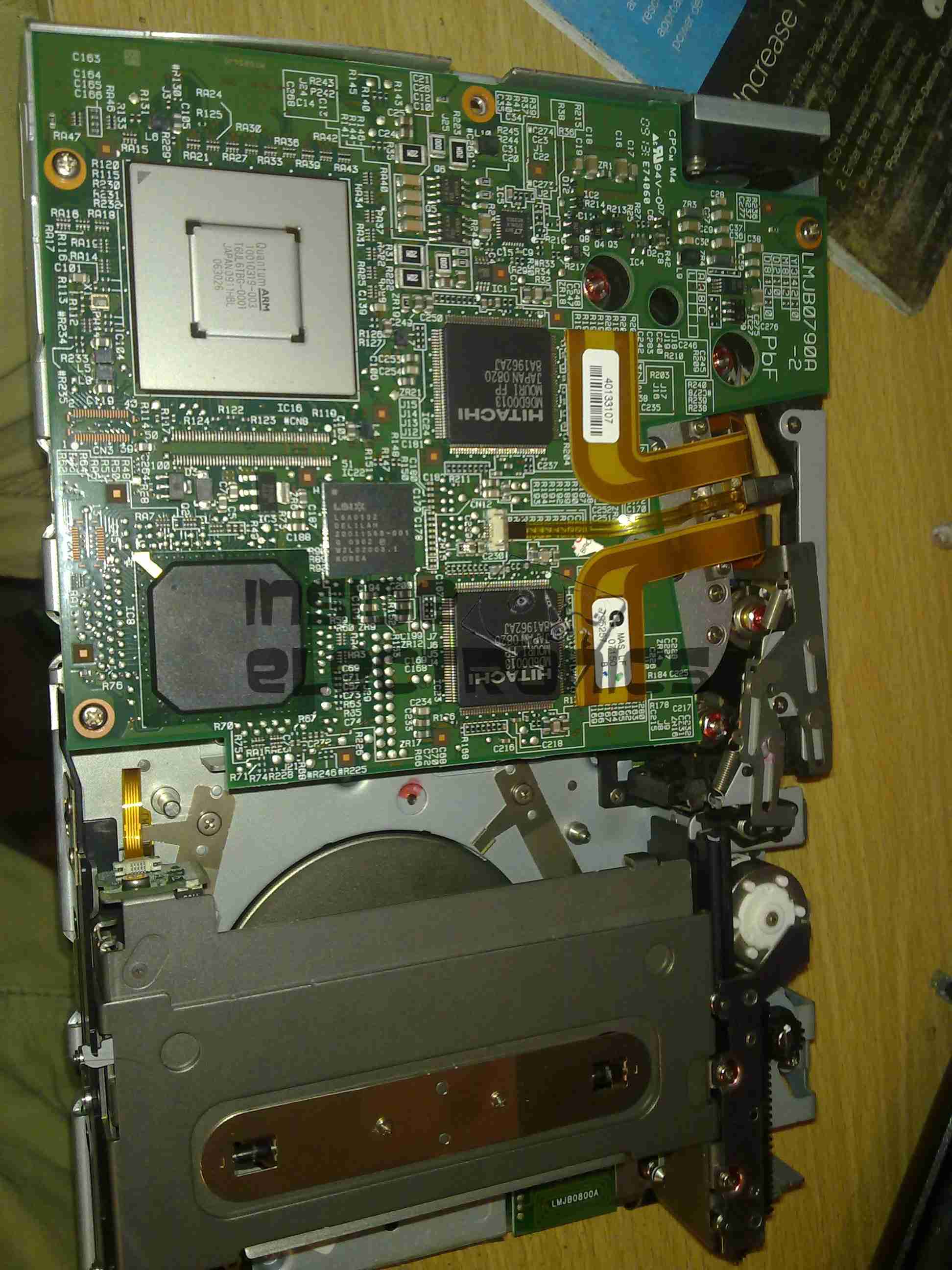
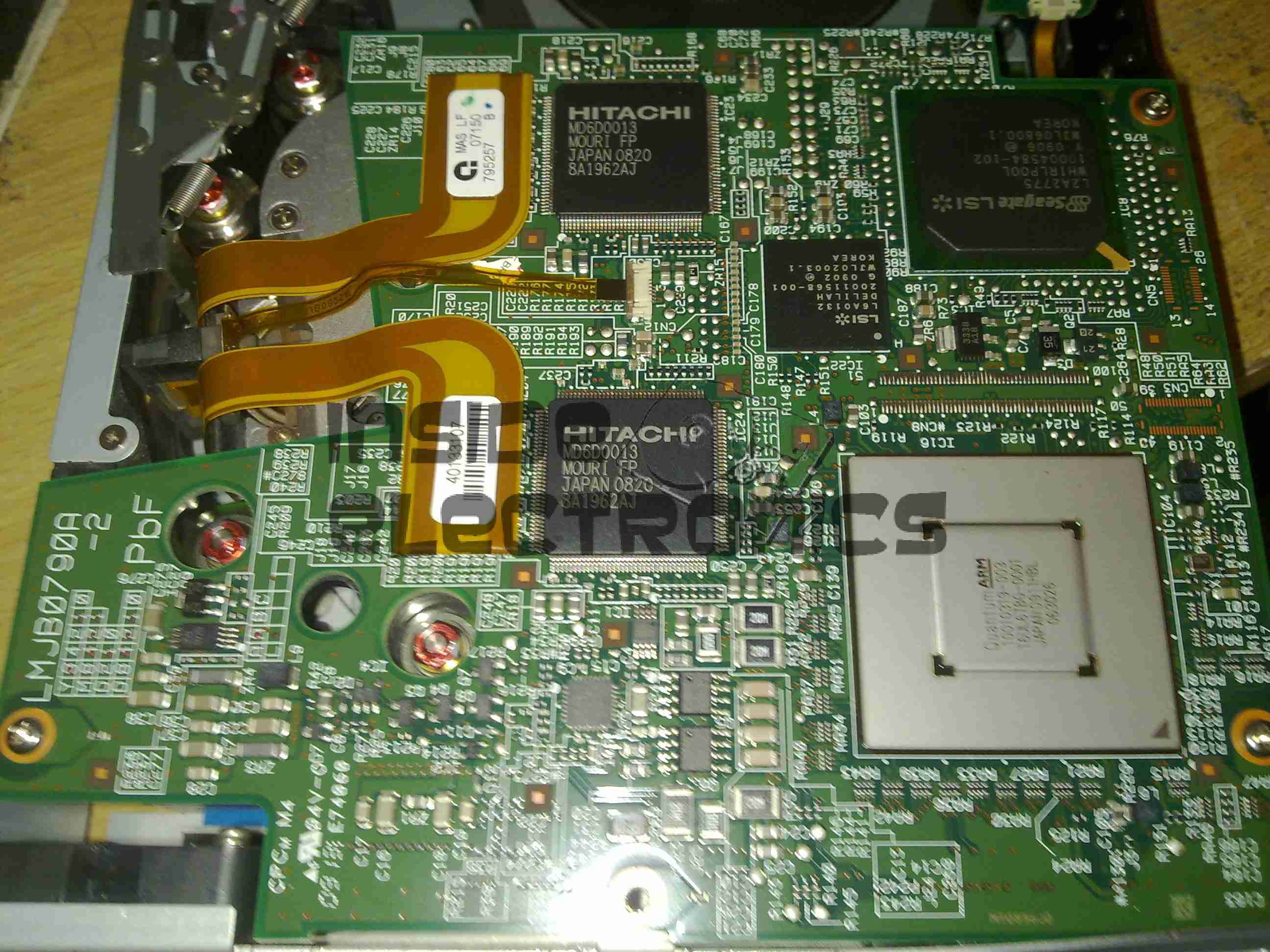
The main camera section process board is above. This board does all the signal processing for the CCD, has the bias voltage supplies and houses the control sections for the motorized parts of the optics assembly. There are quite a few dipped Tantalum capacitors on pigtails, instead of being directly board mounted. This was probably done due to space requirements on the PCB itself.2016-08-20_13-40-11_000357

Under the steel shield on this board is some of the main signal processing for the CCD.

Optics Assembly
Optics Assembly

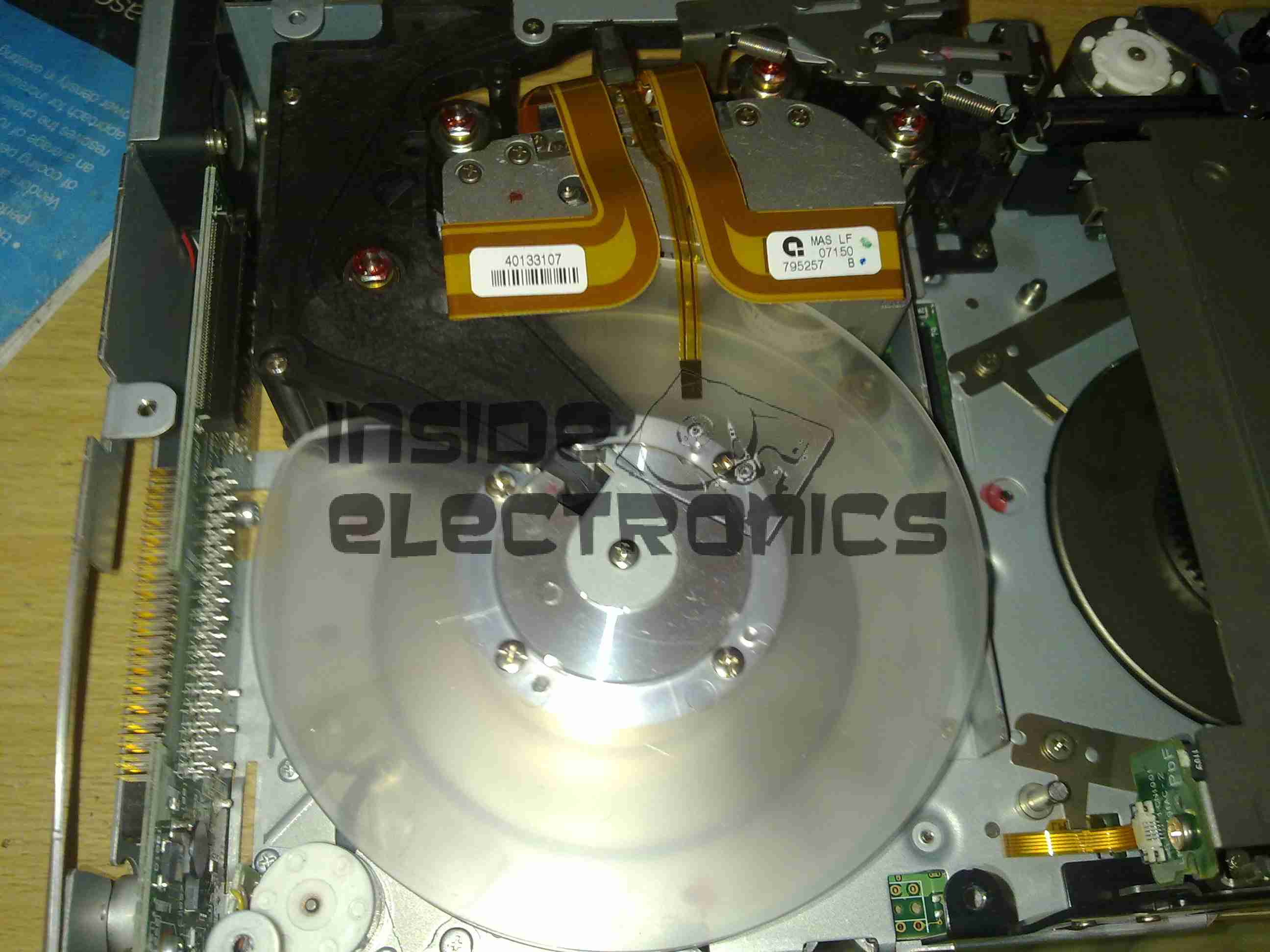
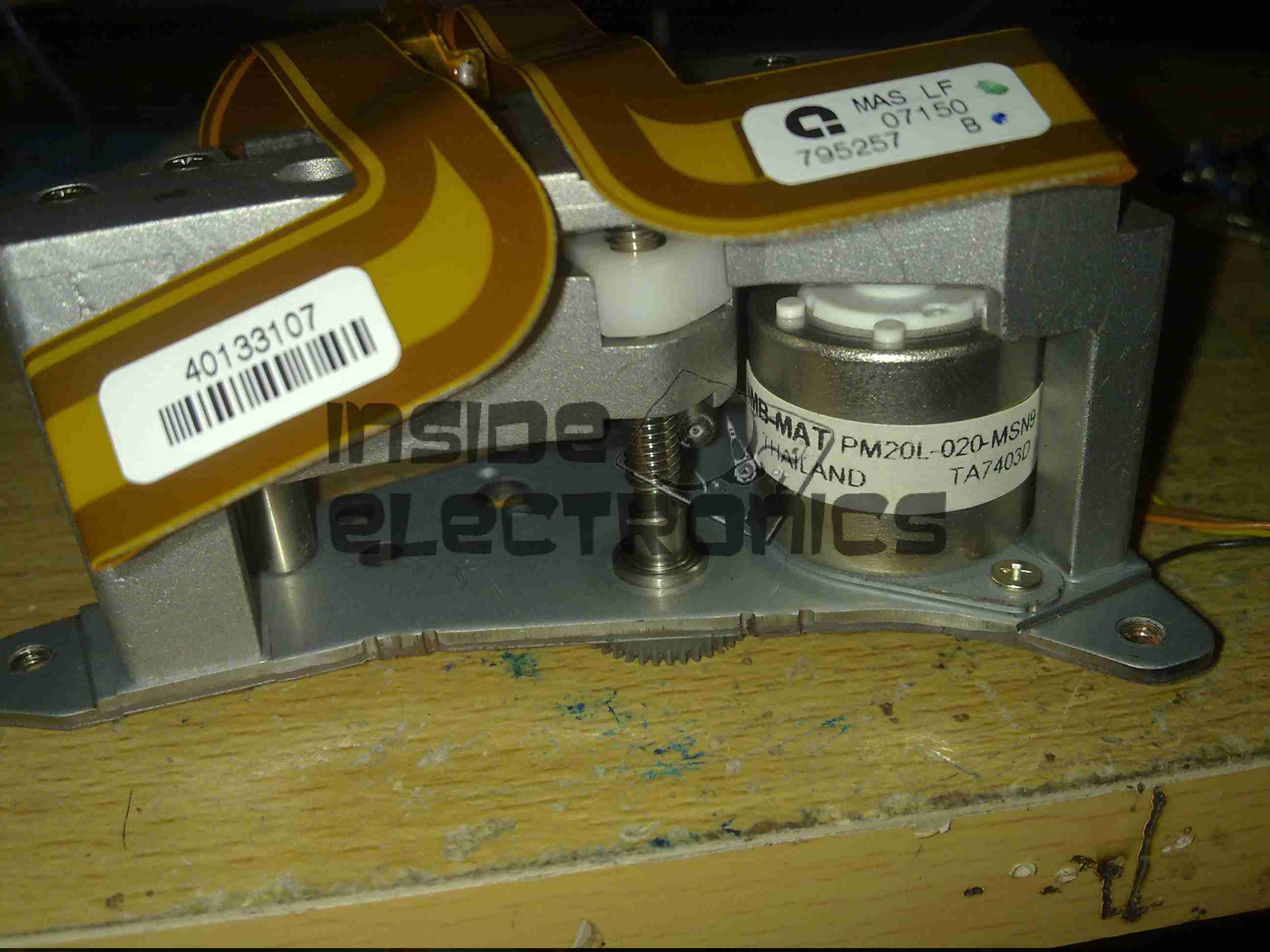
The back of the optics tube is a heavy casting, to supress vibration. This will be more clear later on.

Position Sensor Flex

The position of the lens elements is determined by reflective strips on the barrel & sensors on this flex PCB.

Sub Process Board
Sub Process Board

There’s another small board tucked into the side of the tube, this hooks into the process PCB.

Process Delay Line
Process Delay Line

According to the schematic, there’s nothing much on this board, just a delay line & a few transistors.

Piezo Focus Disc
Piezo Focus Disc

Here’s the reason for the heavy alloy casing at the CCD mounting end of the optics: the fine focus adjustment is done with a piezoelectric disc, the entire CCD assembly is mounted to this board. Applying voltage to the electrodes moves the assembly slightly to alter the position of the CCD. The blue glass in the centre of the unit is the IR filter.

IR Relective Sensors

The barrel position sensors are these IR-reflective type.

Iris Assembly
Iris Assembly

The iris is mounted just before the CCD, this is controlled with a galvanometer-type device with position sensors incorporated.

Iris Opening
Iris Opening

Pushing on the operating lever with the end of my screwdriver opens the leaves of the iris against the return spring.

Tape Transport & Main Control

Main Control Board
Main Control Board

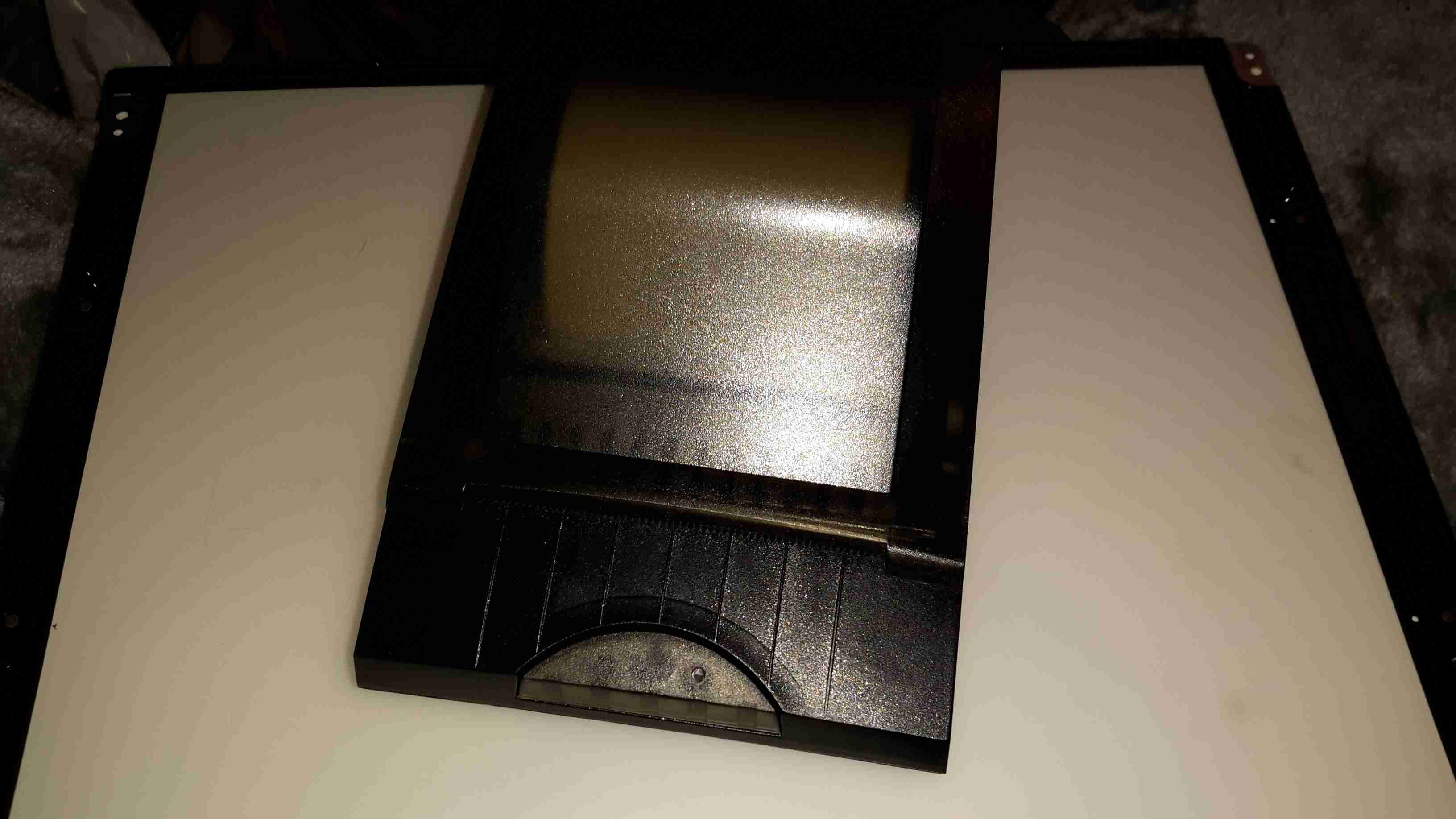
Tucked into the side of the main body of the unit is the main system control board. This PCB houses all the vital functions of the camera: Power Supply, Servo Control, Colour Control,Video Amplifiers, etc.

Tape Drum
Tape Drum

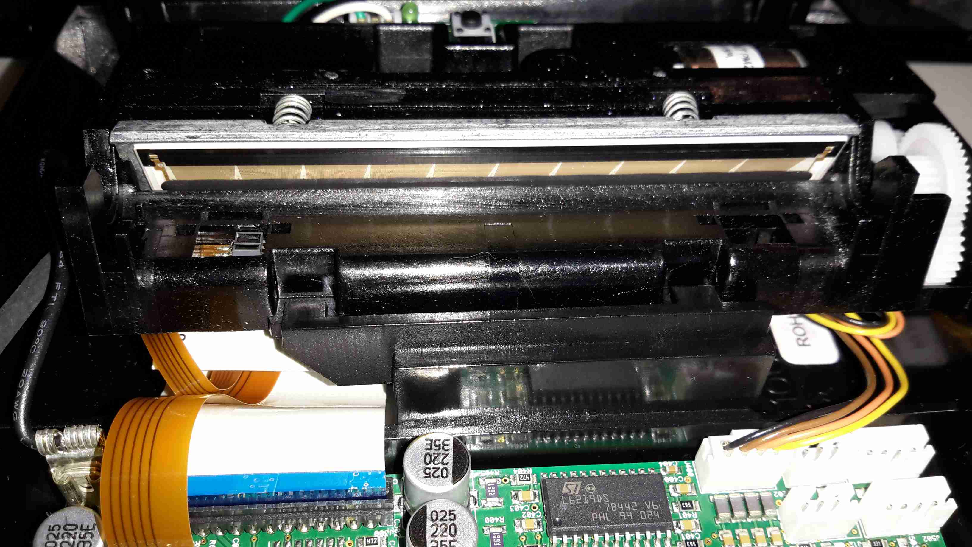
Here’s the main tape transport mechanism, this is made of steel & aluminium stampings for structural support. The drum used in this transport is noticeably smaller than a standard VHS drum, the tape is wrapped around more of the drum surface to compensate.

Tape Transport
Tape Transport

The VHS tape sits in this carriage & the spools drive the supply & take up reels in the cartridge.

Main Control PCB
Main Control PCB

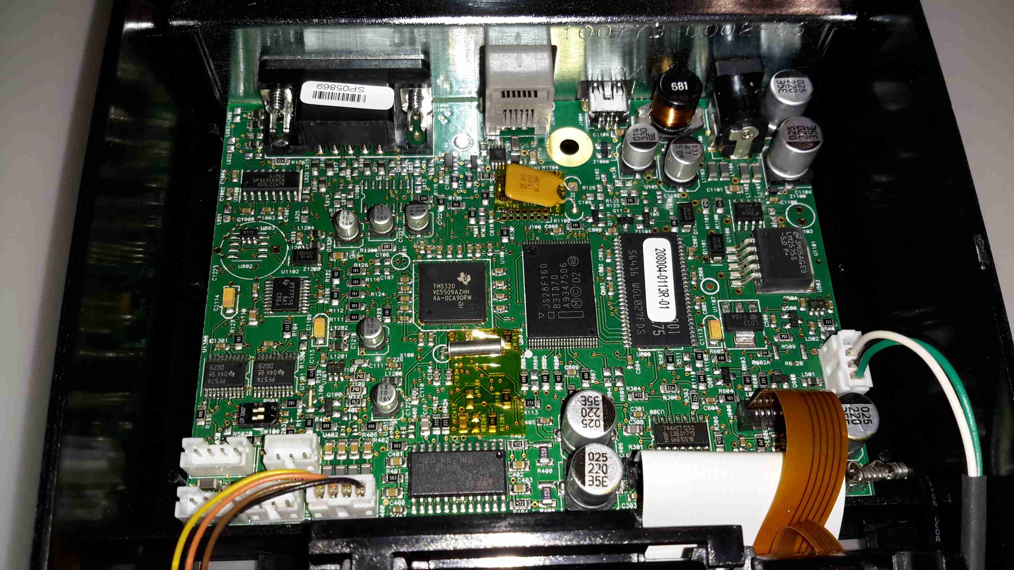
Here’s the component side of the main control PCB. This one is very densely packed with parts, I wouldn’t like to try & troubleshoot something like this!

Main PCB Left
Main PCB Left

The left side has the video head amp at the top, a Panasonic AN3311K 4-head video amp. Below that is video processing, the blue components are the analogue delay lines. There are a couple of hybrid flat-flex PCBs tucked in between with a couple of ICs & many passives. These hybrids handle the luma & chroma signals.
Top left is the capstan motor driver a Rohm BA6430S. The transport motors are all 3-phase brushless, with exception of the loading motor, which is a brushed DC type.

Delay Line
Delay Line

Here’s what is inside the delay lines for the analogue video circuits. The plastic casing holds a felt liner, inside which is the delay line itself.

Internal Glass
Internal Glass

The delay is created by sending an acoustic signal through the quartz crystal inside the device by a piezoelectric transducer, bouncing it off the walls of the crystal before returning it to a similar transducer.

Main PCB Centre
Main PCB Centre

Here’s the centre of the board, the strange crystal at bottom centre is the clock crystal for the head drum servo. Why it has 3 pins I’m not sure, only the two pins to the crystal inside are shown connected on the schematic. Maybe grounding the case?
The main servo controls for the head drum & the capstan motor are top centre, these get a control signal from the tape to lock the speed of the relative components.

Main PCB Right
Main PCB Right

Here’s the right hand side. The main power supply circuitry is at top right, with a large can containing 4 switching inductors & a ferrite pot core transformer. All these converters are controlled by a single BA6149 6-channel DC-DC converter controller IC via a ULN2003 transistor array.
The ceramic hybrid board next to the PSU has 7 switch transistors for driving various indicator LEDs.
The large tabbed IC bottom centre is the loading motor drive, an IC from Mitsubishi, the M54543. This has bidirectional DC control of the motor & built in braking functions. The large quad flat pack IC on the right is the MN1237A on-screen character generator, with the two clock crystals for the main microcontroller.

Erase Head
Erase Head

The full erase head has it’s power supply & oscillator on board, applying 9v to this board results in an AC signal to the head, which erases the old recording from the tape before the new recording is laid down by the flying heads on the drum.

Audio Control PCB
Audio Control PCB

The Audio & Control head is connected to this PCB, which handles both reading back audio from the tape & recording new audio tracks. The audio bias oscillator is on this board, & the onboard microphone feeds it’s signal here. The control head is fed directly through to the servo section of the main board.

Drum Motor
Drum Motor

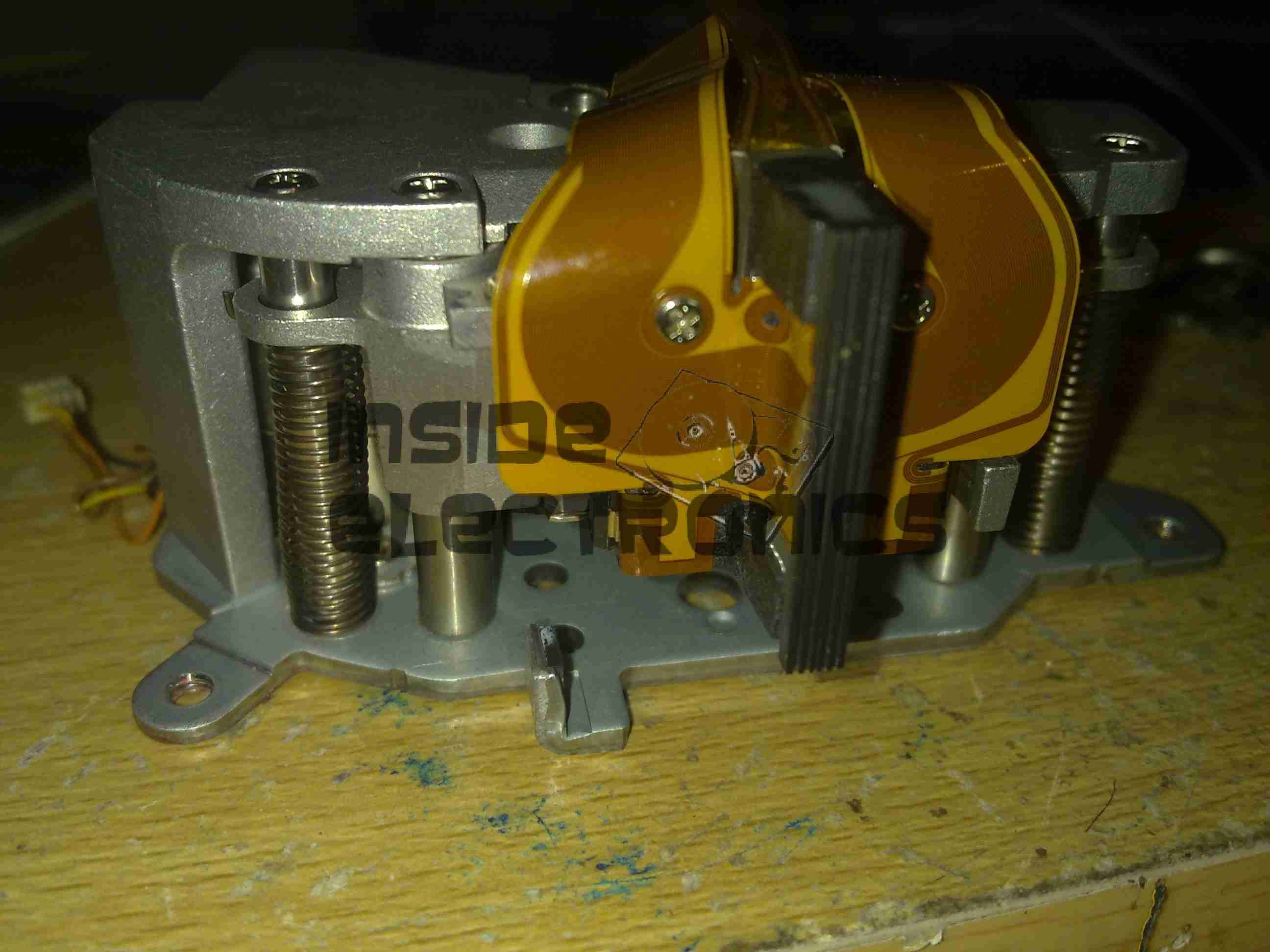
The motor that drives the head drum is another DC brushless 3-phase type.

Hall Sensors
Hall Sensors

These 3 Hall sensors are used by the motor drive to determine the rotor position & time commutation accordingly.

Stator
Stator

The stator on this motor is of interesting construction, with no laminated core, the coils are moulded into the plastic holder. The tach sensor is on the side of the stator core. This senses a small magnet on the outside of the rotor to determine rotational speed. For PAL recordings, the drum rotates at 1500 RPM.

Motor Removed
Motor Removed

Not much under the stator other than the bearing housing & the feedthrough to the rotary transformer.

Head Disc
Head Disc

The heads are mounted onto the top disc of the drum, 4 heads in this recorder. The signals are transmitted to the rotating section through the ferrite rotary transformer on the bottom section.

Head Chip
Head Chip

The tiny winding of the ferrite video head can just about be seen on the end of the brass mounting.

Capstan Motor Components

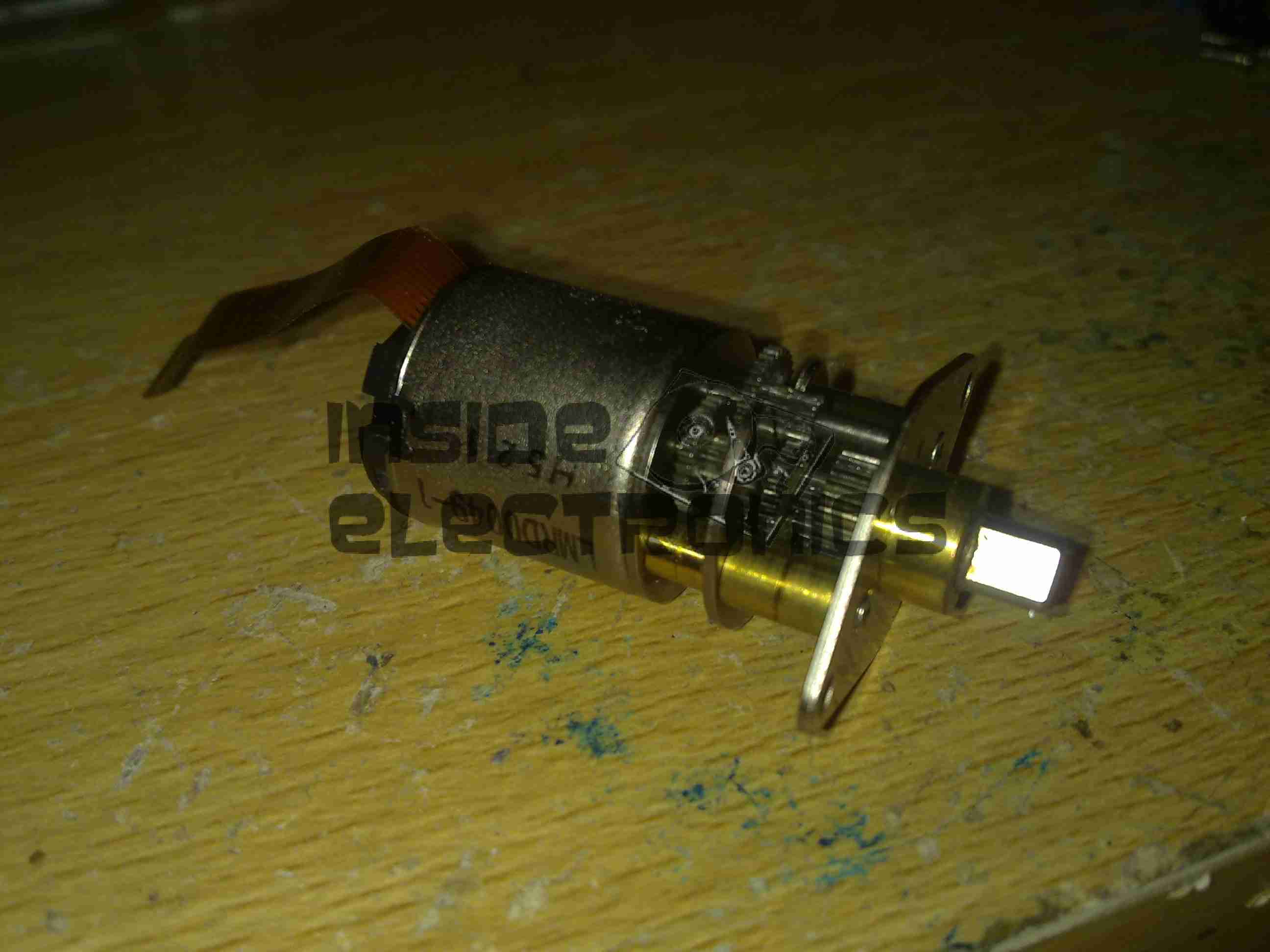
The capstan motor is similar to the drum motor, only this one is flat. The rotor has a ferrite magnet, in this case it wasn’t glued in place, just held by it’s magnetic field.

Capstan Motor Stator

The PCB on this motor has a steel backing to complete the magnetic circuit, the coils for the 3 motor phases are simply glued in place. The Hall sensors on this motor are placed in the middle of the windings though.
Again there is a tach sensor on the edge of the board that communicates the speed back to the controller. This allows the servo to remain locked at constant speed.

Viewfinder

Viewfinder Assembly
Viewfinder Assembly

As usual with these cameras, this section is the CRT based viewfinder. These units take the composite signal from the camera to display the scene. This one has many more pins than the usual viewfinder. I’ll hack a manual input into this, but I’ll leave that for another post.

Viewfinder Circuits
Viewfinder Circuits

Being an older camera than the ones I’ve had before, this one is on a pair of PCBs, which are both single-sided.

Main Viewfinder Board

The main board has all the power components for driving the CRT & some of the adjustments. The main HV flyback transformer is on the right. This part creates both the final anode voltage for the tube & the focus/grid voltages.

Viewfinder Control PCB Top

The viewfinder control IC is on a separate daughter board in this camera, with two more controls.

Control IC
Control IC

The control IC is a Matsushita AN2510S, this has all the logic required to separate the sync pulses from the composite signal & generate an image on the CRT.

Viewfinder CRT Frame

The recording indicator LEDs are mounted in the frame of the CRT & appear above the image in the viewfinder.

Viewfinder CRT With Yoke

Here the CRT has been separated from the rest of the circuitry with just the deflection yoke still attached.

M01JPG5WB CRT
M01JPG5WB CRT

The electron gun in this viewfinder CRT is massive in comparison to the others that I have seen, and the neck of the tube is also much wider. These old tubes were very well manufactured.

Viewfinder Optics
Viewfinder Optics

A simple mirror & magnifying lens completes the viewfinder unit.

Posted on Leave a comment

Nanoptix “Spill-Proof” Thermal Receipt Printer

Nanoptix Spill-Proof Thermal Printer

I have yet another receipt printer, this one appears to be brand new. It’s possibly the smallest thermal 80mm printer I have at the moment, and has both USB & Serial interfaces.

Controller PCB
Controller PCB

There’s not much to these printers at all. Removing a single screw allows the case halves to separate, showing the guts. The controller is based around a Texas Instruments TMS320VC5509AFixed-Point DSP. It’s associated Flash ROM & RAM are to the right.
Power supply is dealt with in the top right of the PCB, with the interface ports further left.

Print Head
Print Head

Here’s the thermal mechanism itself, with the large print head. The stepper motor to drive the paper through the printer is just peeking out at top right. The paper present sensor is just under the left hand side of the print head.

Posted on Leave a comment

Quantum LTO2 CL1001 Tape Drive Teardown

Drive Top
Drive Top

I have recently begun to create an archive of all my personal data, and since LTO2 tape drives offer significant capacity (200GB/400GB) per tape, longevity is very high (up to 30 years in archive), & relatively low cost, this is the technology I’ve chosen to use for my long term archiving needs.

Unfortunately, this drive was DOA, due to being dropped in shipping. This drop broke the SCSI LVD connector on the back of the unit, & bent the frame, as can be seen below.

Broken SCSI
Broken SCSI

As this drive is unusable, it made for a good teardown candidate.

Cover Removed
Cover Removed

Here the top cover of the drive has been removed, showing the top of the main logic PCB. The large silver IC in the top corner is the main CPU for the drive. It’s a custom part, but it does have an ARM core.

The two Hitachi ICs are the R/W head interface chipset, while the smaller LSI IC is the SCSI controller.
The tape transport & loading mech can be seen in the lower half of the picture.

Main Logic
Main Logic

Close up of the main logic.

Tape Spool
Tape Spool

Here the main logic PCB has been removed, showing the tape take up spool. The data cartridges have only one spool to make the size smaller. When the tape is loaded, the drive grabs onto the leader pin at the end of the tape & feeds it onto this spool.
The head assembly is just above the spool.

Bottom Plate Removed

Bottom of the drive with the cover plate removed. Here the spindle drive motors are visible, both brushless 3-Phase units. Both of these motors are driven by a single controller IC on the other side of the lower logic PCB.

Head Drive Motor
Head Drive Motor

The head is moved up & down the face of the tape by this stepper motor for coarse control, while fine control is provided by a voice coil assembly buried inside the head mount.

Tape Head Assembly
Tape Head Assembly

The face of the tape R/W head. This unit contains 2 sets of 8 heads, one of which writes to the tape, the other then reads the written data back right after to verify integrity.

Cartridge Load Motor

The tape cartridge loading motor. I originally thought that this was a standard brushed motor, but it has a ribbon cable emerging, this must be some sort of brushless arrangement.

A replacement drive is on the way, I shall be documenting some more of my archiving efforts & system setup once that unit arrives.

Posted on Leave a comment

Zebra P330i Card Printer

Front
Front

This is the teardown of a Zebra P330i plastic card printer, used for creating ID cards, membership cards, employee cards, etc. I got this as a faulty unit, which I will detail later on.
This printer supports printing on plastic cards from 1-30mils thick, using dye sublimation & thermal transfer type printing methods. Interfaces supplied are USB & Ethernet. The unit also has the capability to be fitted with a mag stripe encoder & a smart card encoder, for extra cost.

Print Engine
Print Engine


On the left here is the print engine open, the blue cartridge on the right is a cleaning unit, using an adhesive roller to remove any dirt from the incoming card stock.
This is extremely important on a dye sublimation based printing engine as any dirt on the cards will cause printing problems.

Cards In Feeder
Cards In Feeder


Here on the right is the card feeder unit, stocked with cards. This can take up to 100 cards from the factory.
The blue lever on the left is used to set the card thickness being used, to prevent misfeeds. There is a rubber gate in the intake port of the printer which is moved by this lever to stop any more than a single card from being fed into the print engine at any one time.

Card Feeder Belt
Card Feeder Belt


Here is the empty card feeder, showing the rubber conveyor belt. This unit was in fact the problem with the printer, the drive belt from the DC motor under this unit was stripped, preventing the cards from feeding into the printer.

Print Head
Print Head


Here is a closeup of the print head assembly. The brown/black stripe along the edge is the row of thin-film heating elements. This is a 300DPI head.


Print Station
Print Station


This is under the print head, the black roller on the left is the platen roller, which supports the card during printing. The spool in the center of the picture is the supply spool for the dye ribbon.
In the front of the black bar in the bottom center, is a two-colour sensor, used to locate the ribbon at the start of the Yellow panel to begin printing.

LCD PCB
LCD PCB


Inside the top cover is the indicator LCD, the back of which is pictured right.
This is a 16×1 character LCD from Hantronix. This unit has a parallel interface.

LCD
LCD


Front of the LCD, this is white characters on a blue background.

Roller Drive Belts
Roller Drive Belts


Here is the cover removed from the printer, showing the drive belts powering the drive rollers. There is an identical arrangement on the other side of the print engine running the other rollers at the input side of the engine.

Mains Filter
Mains Filter


Here the back panel has been removed from the entire print engine, complete with the mains input wiring & RFI filtering.
This unit has excellent build quality, just what is to be expected from a £1,200+ piece of industrial equipment.

Main Frame With Motors


The bottom of the print engine, with all the main wiring & PCB removed, showing the main drive motors. The left hand geared motor operates the head lift, the centre motor is a stepper, which operates the main transmission for the cards. The right motor drives the ribbon take up spindle through an O-Ring belt.

Feeder Drive Motor
Feeder Drive Motor


Card feeder drive motor, this connects to the belt assembly through a timing belt identical to the roller drive system.
All these DC geared motors are 18v DC, of varying torque ratings.

Power Supply
Power Supply


Here is the main power supply, a universal input switch-mode unit, outputting 24v DC at 3.3A.

PSU Label
PSU Label


PSU info. This is obviously an off the shelf unit, manufactured by Hitek. Model number FUEA240.

Print Engine Rear
Print Engine Rear


The PSU has been removed from the back of the print engine, here is shown the remaining mechanical systems of the printer.

Print Engine Components


A further closeup of the print engine mechanical bay, the main stepper motor is bottom centre, driving the brass flywheel through another timing belt drive. The O-Ring drive on the right is for the ribbon take up reel, with the final motor driving the plastic cam on the left to raise/lower the print head assembly.
The brass disc at the top is connected through a friction clutch to the ribbon supply reel, which provides tension to keep it taut. The slots in the disc are to sense the speed of the ribbon during printing, which allows the printer to tell if there is no ribbon present or if it has broken.

RFID PCB
RFID PCB

Here is a further closeup, showing the RFID PCB behind the main transmission. This allows the printer to identify the ribbon fitted as a colour or monochrome.
The antenna is under the brass interrupter disc on the left.

I/O Daughterboard
I/O Daughterboard


The I/O daughterboard connects to the main CPU board & interfaces all the motors & sensors in the printer.

Main PCB
Main PCB

Here is the main CPU board, which contains all the logic & processing power in the printer.

CPU
CPU


Main CPU. This is a Freescale Semiconductor part, model number MCF5206FT33A, a ColdFire based 32-bit CPU. Also the system ROM & RAM can be seen on the right hand side of this picture.

Ethernet Interface
Ethernet Interface


Bottom of the Ethernet interface card, this clearly has it’s own RAM, ROM & FPGA. This is due to this component being a full Parallel interface print server.

Ethernet Interface Top


Top of the PCB, showing the main processor of the print server. This has a ferrite sheet glued to the top, for interference protection.