As one of my current projects involves a small petrol engine – a Honda GX35 clone, I figured an hour counter would be very handy to keep an eye on service intervals. (More to come on the engine itself later on). I found a device that would suit my needs on good old eBay.
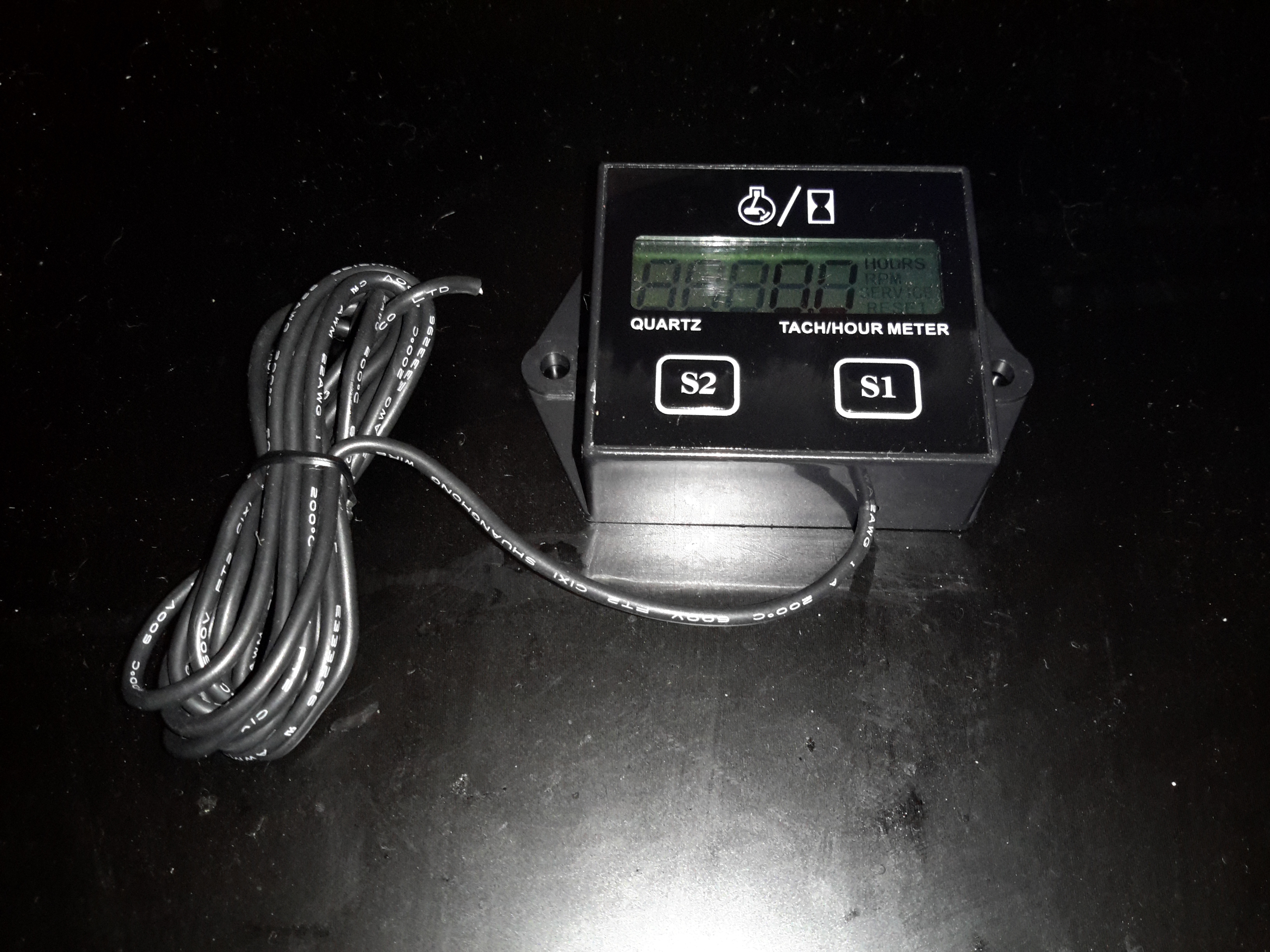
Inductive Engine Monitor
These engine monitors are pretty cheap, at about £4. The sensing is done by a single heat-resistant silicone wire, that wraps around the HT lead to the spark plug. The unit can be set for different firing intervals via the buttons. In the case of most single-cylinder 4-stroke engines, the spark plug fires on every revolution – wasted-spark ignition. This simplifies the ignition system greatly, by not requiring the timing signal be driven from 1/2 crankshaft speed. The second “wasted” spark fires into the exhaust stroke, so has no effect.
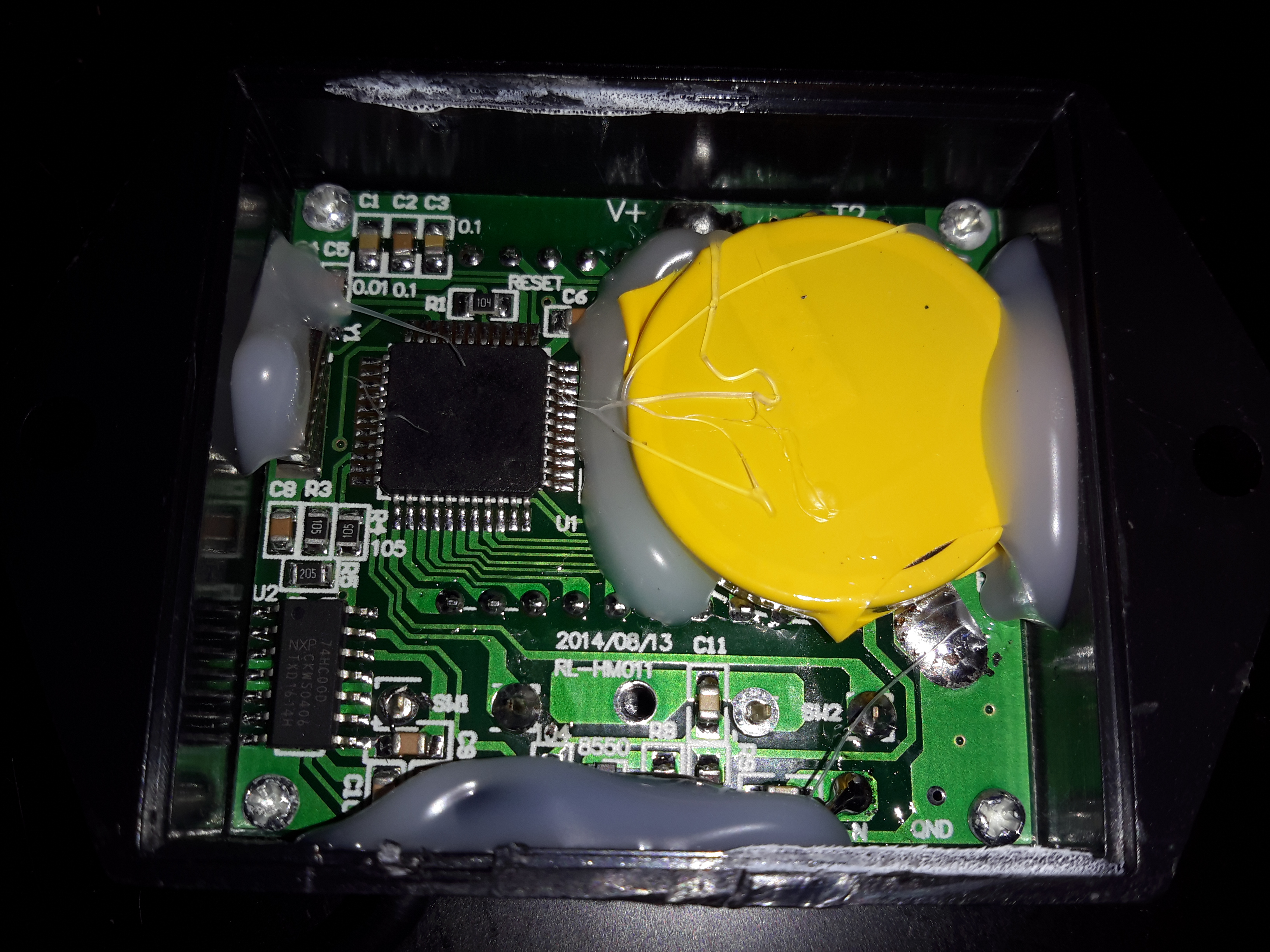
Internals
The back cover is lightly glued into place with a drop of cyanoacrylate in opposite corners, but easily pops off. The power is supplied by a soldered-in 3v Lithium cell. The main microcontroller has no number laser etched on to it at all – it appears it skipped the marking machine.
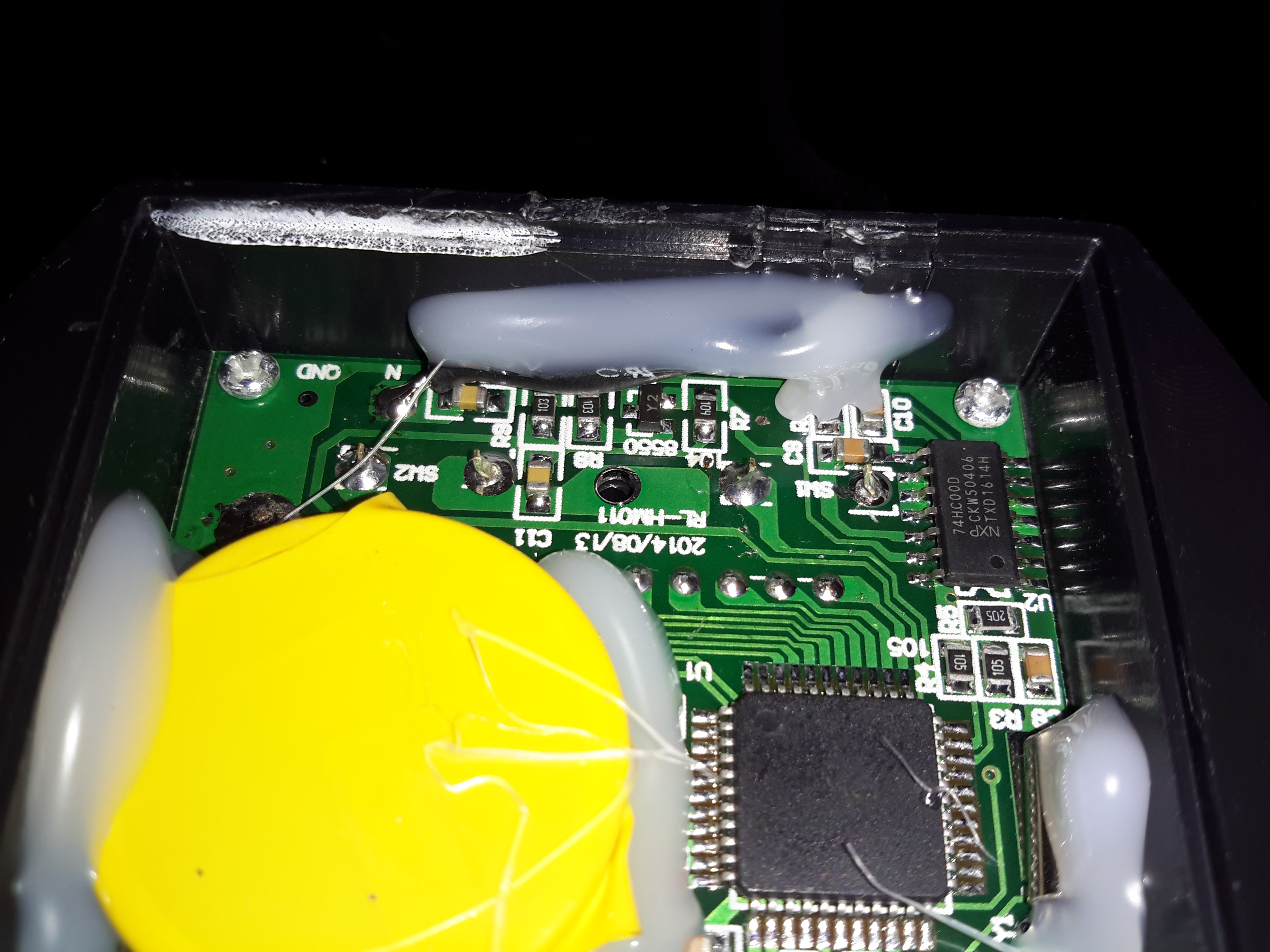
Input Filtering
The input from the sensing wire comes in through a coupling capacitor & is amplified by a transistor. It’s then fed into a 74HC00D Quad 2-Input NAND gate, before being fed into the microcontroller.
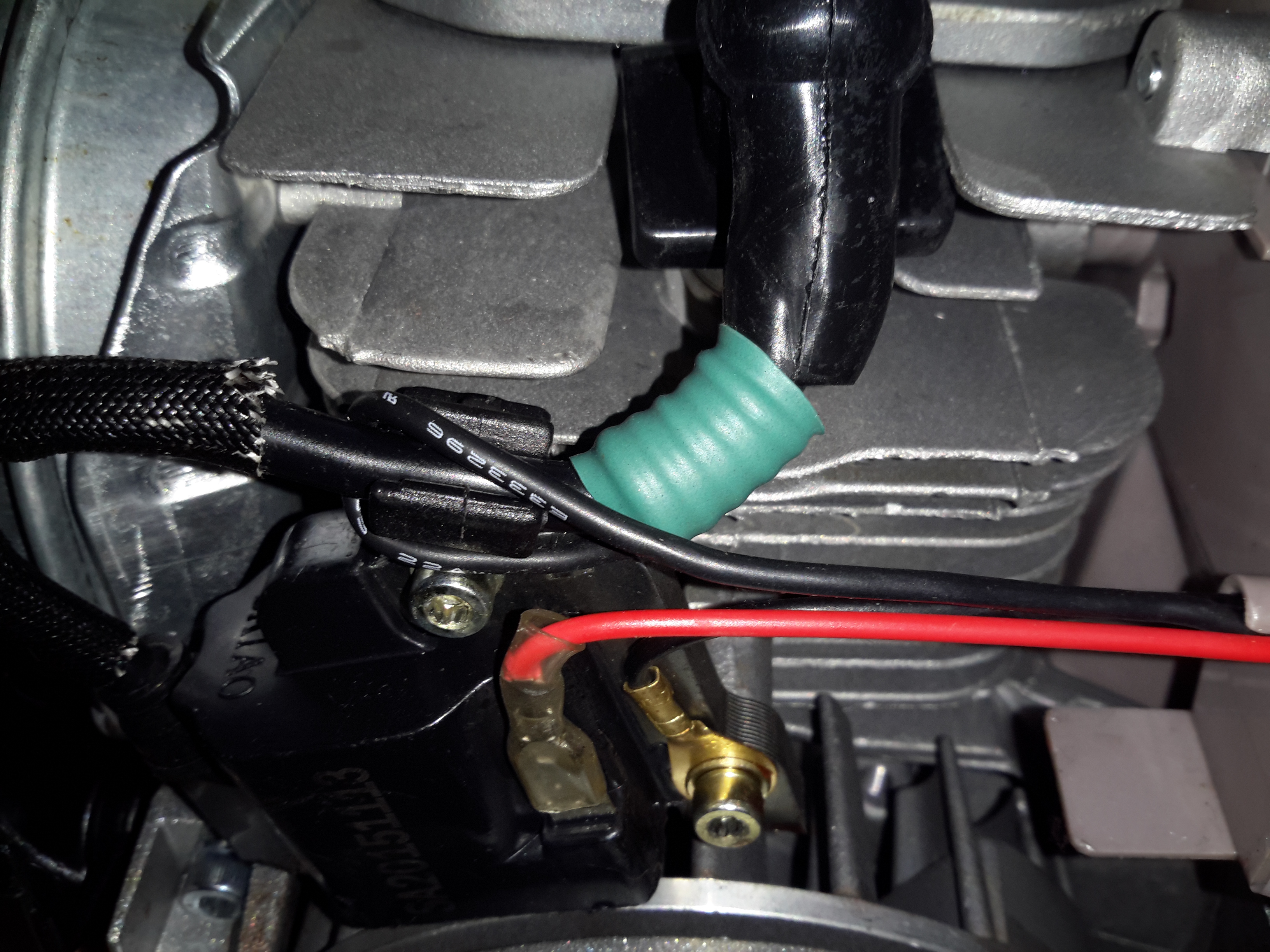
Pickup
The pickup wire is simply wound around the spark plug lead. I’ve held it in position here with some heatshrink tubing. Heat in this area shouldn’t be an issue as it’s directly in the airflow from the flywheel fan.
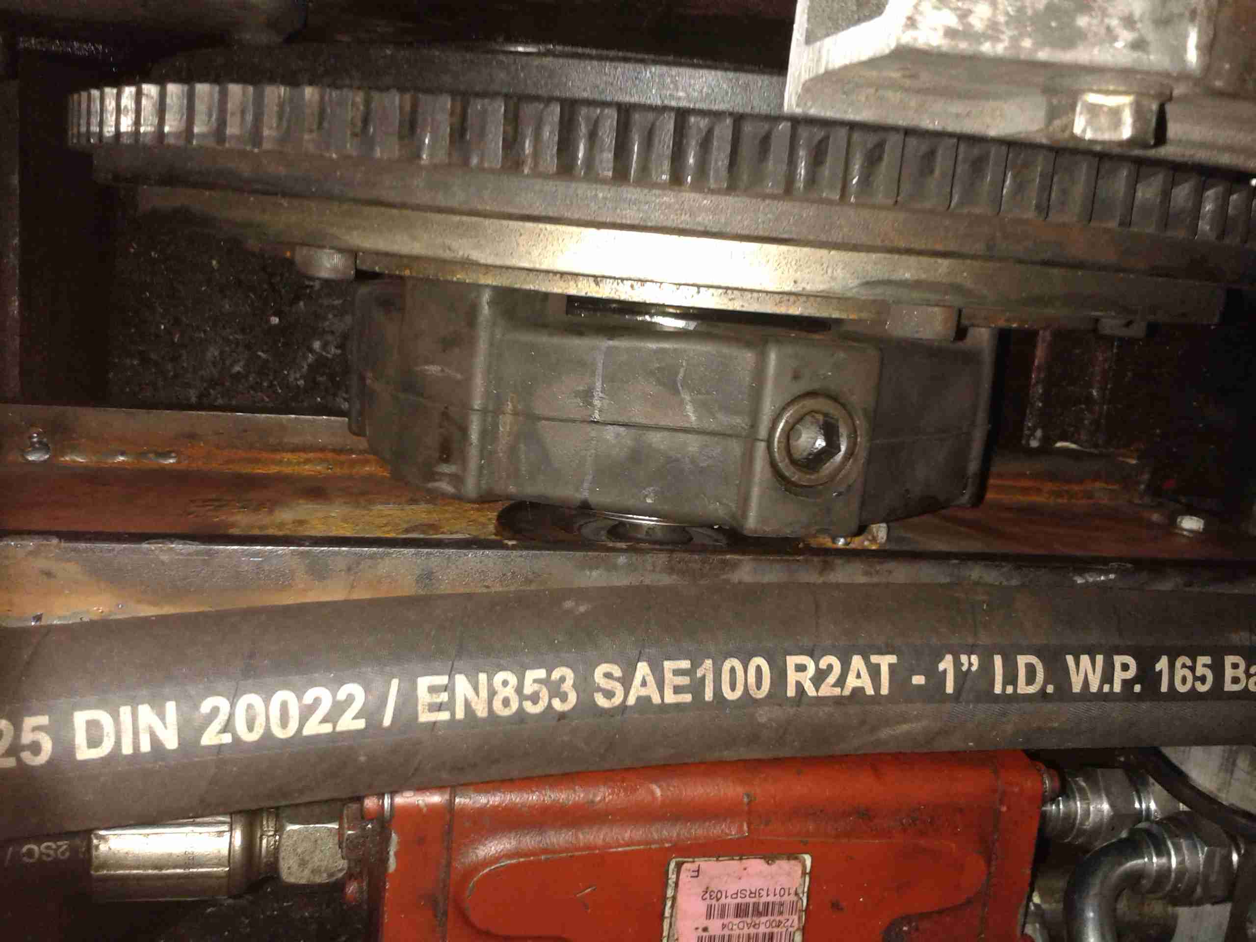
It’s time for the final part of getting the boat’s engine & drive back together, now I have the new coupling hub. I decided to address one of the issues with the pump mounting while I had everything in bits. When the hydraulic drive was installed, a custom plate was laser cut to fit the pump stack to, as we had no bellhousing with a standard mounting pattern.
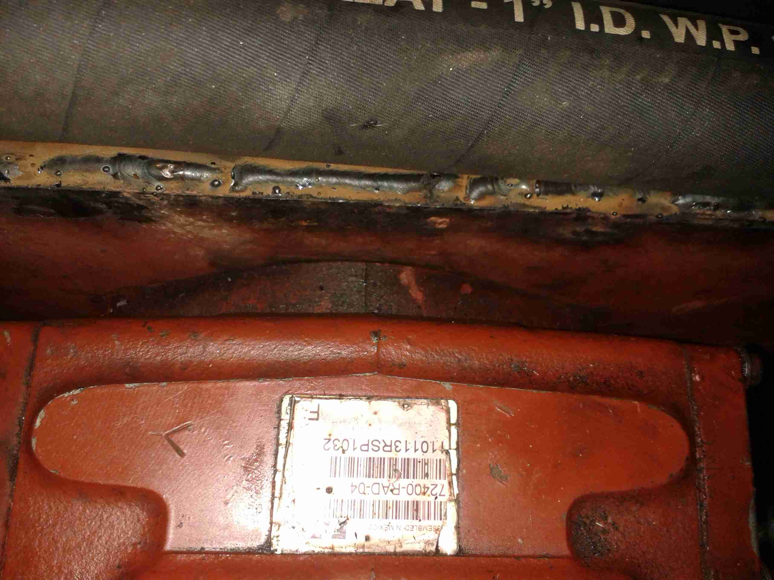
Even though this plate is 10mm steel, under full load it actually bends – so to strengthen it along the long edge, I have welded a pair of ribs to the plate.
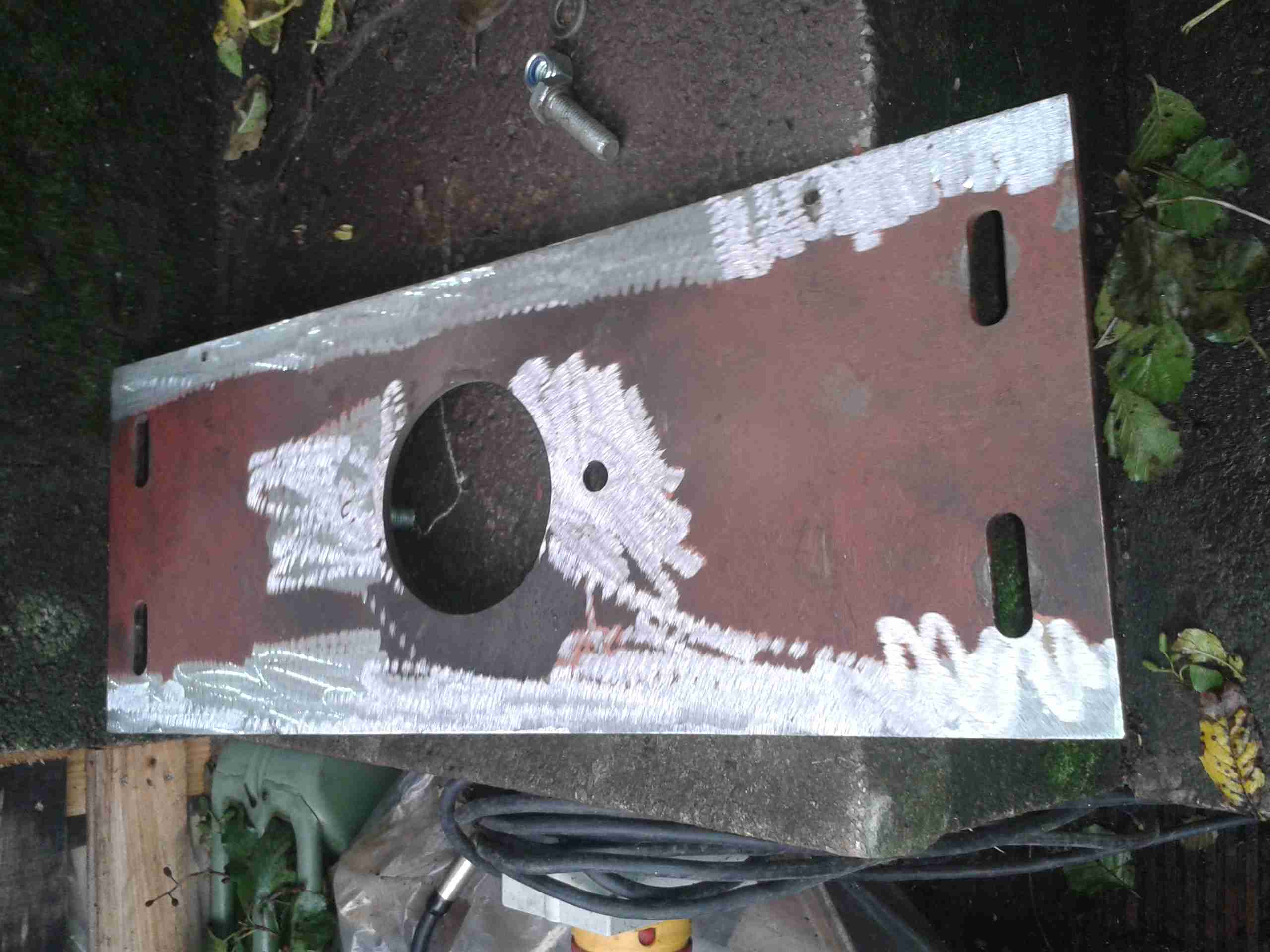
Pump Mounting Plate
The mounting plate as removed from the mounting brackets. The slotted holes at the sides allow for some movement to adjust the position of the pump & flywheel coupling.
Prepared For Welding
I ground off the paint & grease with an abrasive disc, and am replacing one of the pump mounting studs while I’m at it.
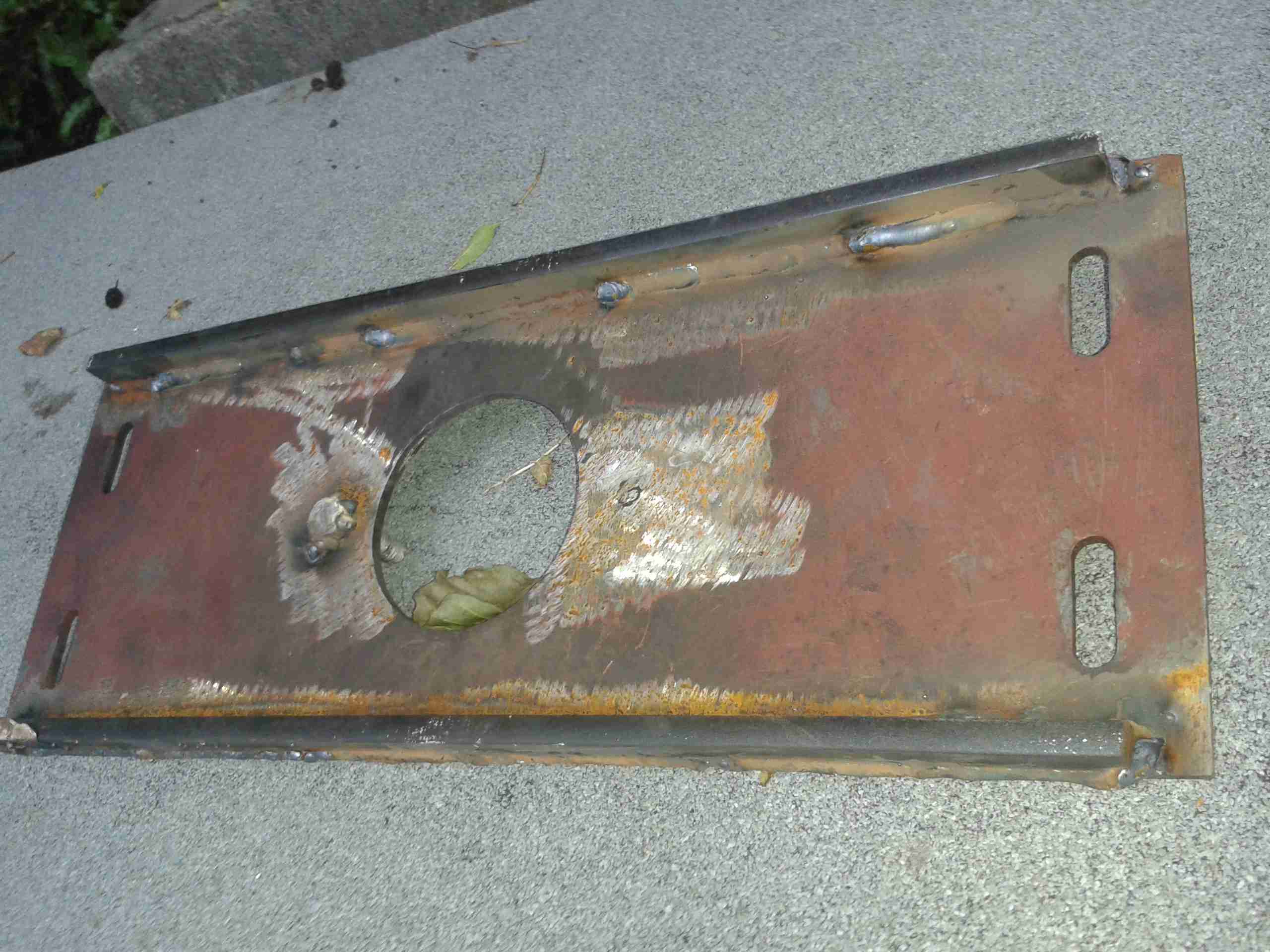
Strengthening Ribs
Here’s the plate after welding. a pair of 10mm bars have been attached along the edges, this will give the mounting significantly more strength on the long axis & prevent any deformation.
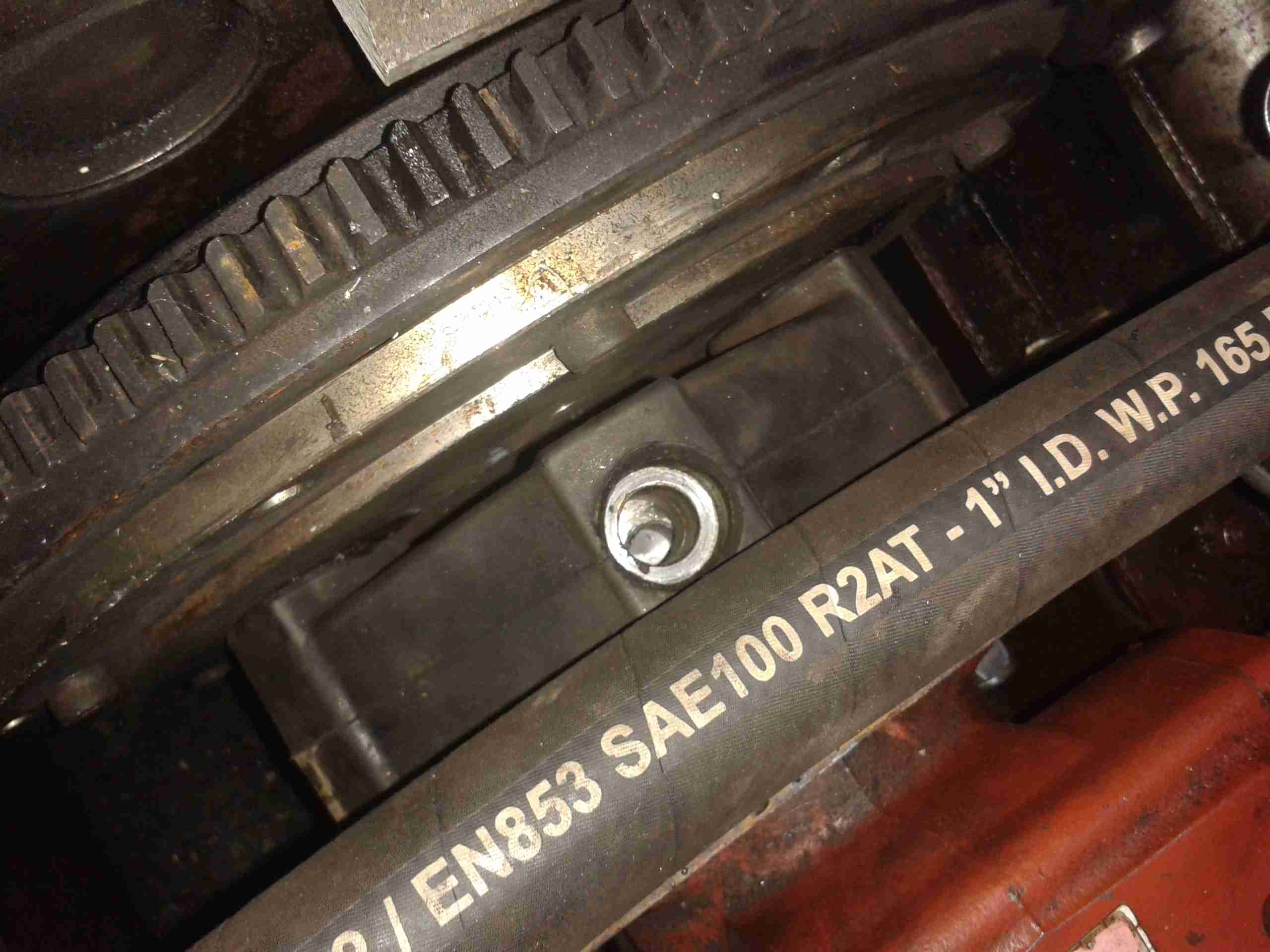
Pump On Hoist
Here the plate has been loosely mounted on it’s brackets, & I’ve got the pump stack with it’s associated tangle of hoses on the chain hoist. This unit is very heavy on it’s own – a 2 man job to lift it into place on it’s mounts – with the very stiff hydraulic hoses attached & filled with oil it’s absolutely unmanageable.
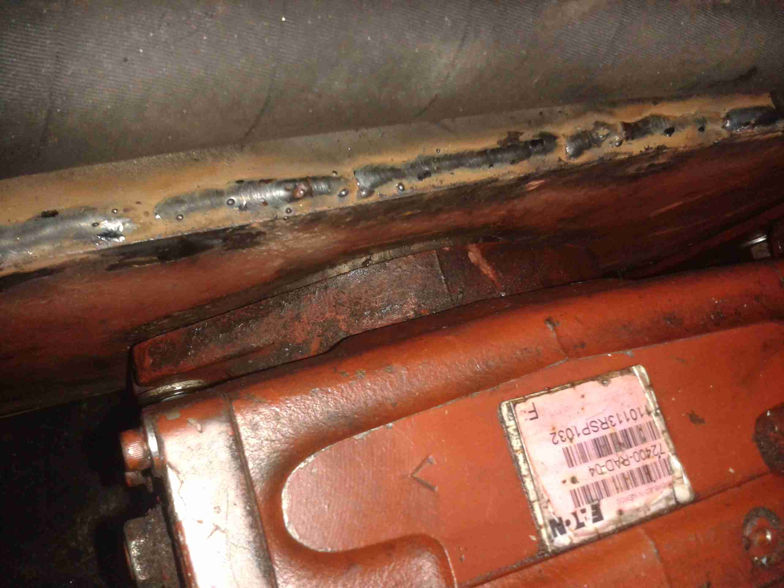
Lining Up The Mountings
Here the pump is being jostled into place. The central hole in the mounting plate is a very snug fit, if the pump doesn’t go in exactly straight it will jam & cause damage to both parts. The mating hole in the coupling hub can be seen here – it’s not quite lined up yet.
Almost There
We’ve got about 10mm to go before the pump is seated. It’s held in place with a pair of large studs & nuts.
Coupling Connected
Here the pump is fitted enough to get the main mounting bolts into the coupling. These are torqued down to 150ft/lbs – a difficult thing to do considering the restricted space in the engine bay.
Flush Mounting
The pump has been pulled down onto the plate evenly with the mounting studs, and is now completely flush with the plate. As can be seen, I didn’t bother tidying up the welds with a grinder, they aren’t in any visible place in normal operation, so it didn’t warrant the effort.
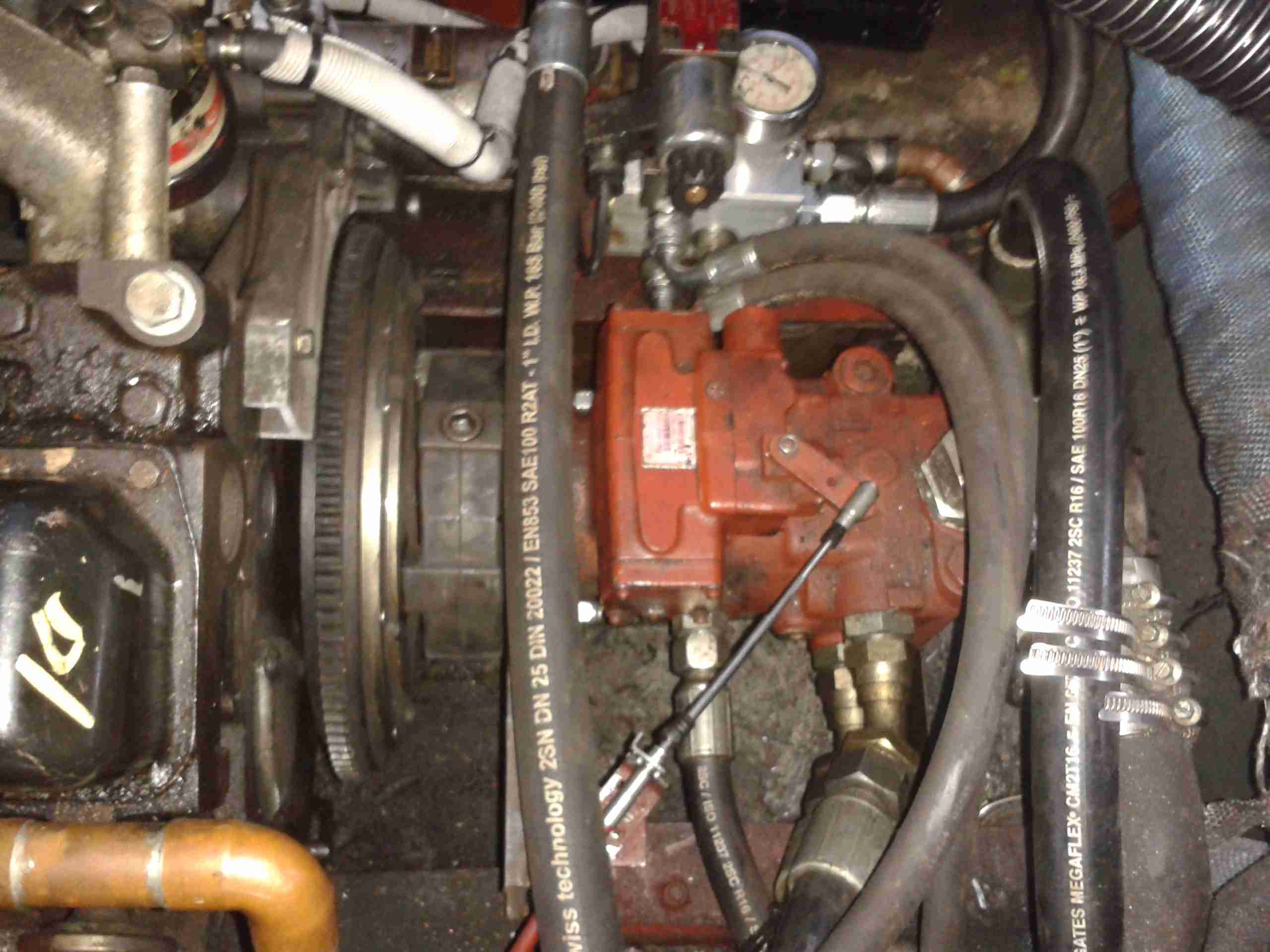
Pump Refitted
Finally, the control cable is reattached to the pump’s control lever & everything is installed! A short test trip proved that everything was stable & no undue movement of the pump or coupling was noticed.
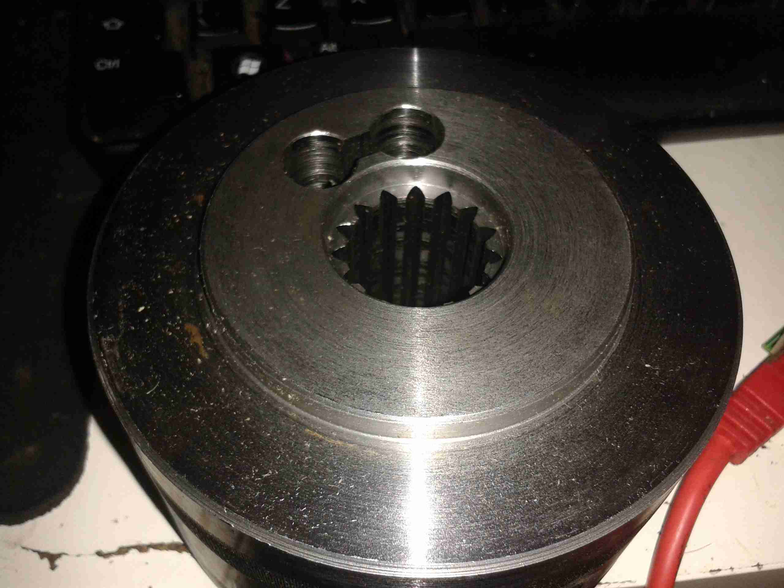
Time to get on with the job now the parts have arrived! Above is the new coupling hub, as can be seen compared to the old one that I previously posted about, this one has it’s full complement of splines.
Rubber Element
The hub bolts into the centre of this rubber coupling, which itself locates on pins attached to the engine’s flywheel. This part wasn’t damaged so it’s being reused with the new hub.
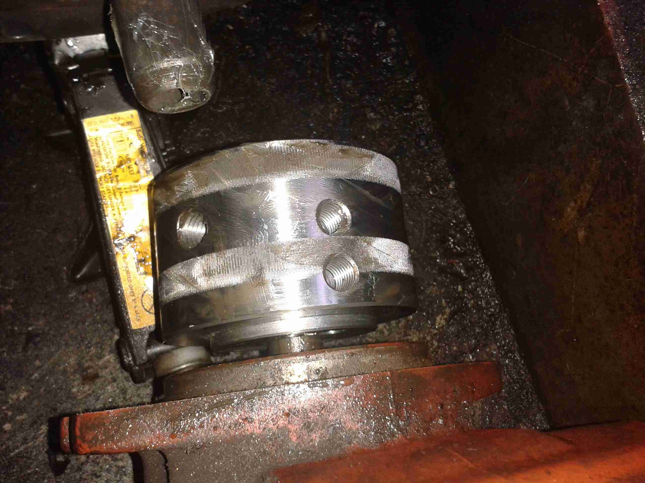
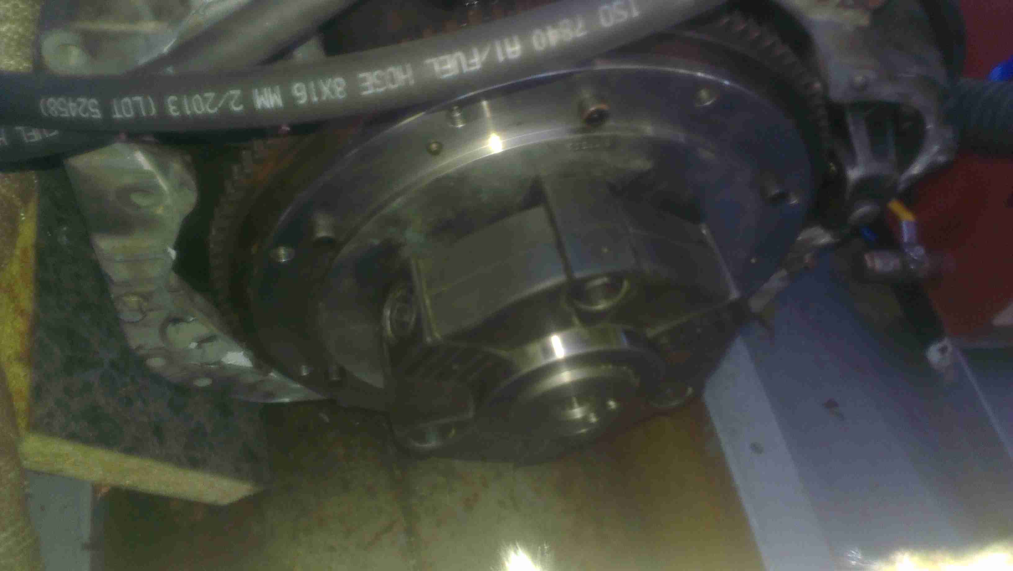
Hub Installed
Here’s the hub installed on the input shaft of the main hydraulic pump stack, the pair of holes on the side of the hub are for the grub screws that secure the coupling on the splines. These screws coming loose are what destroyed the old coupling.
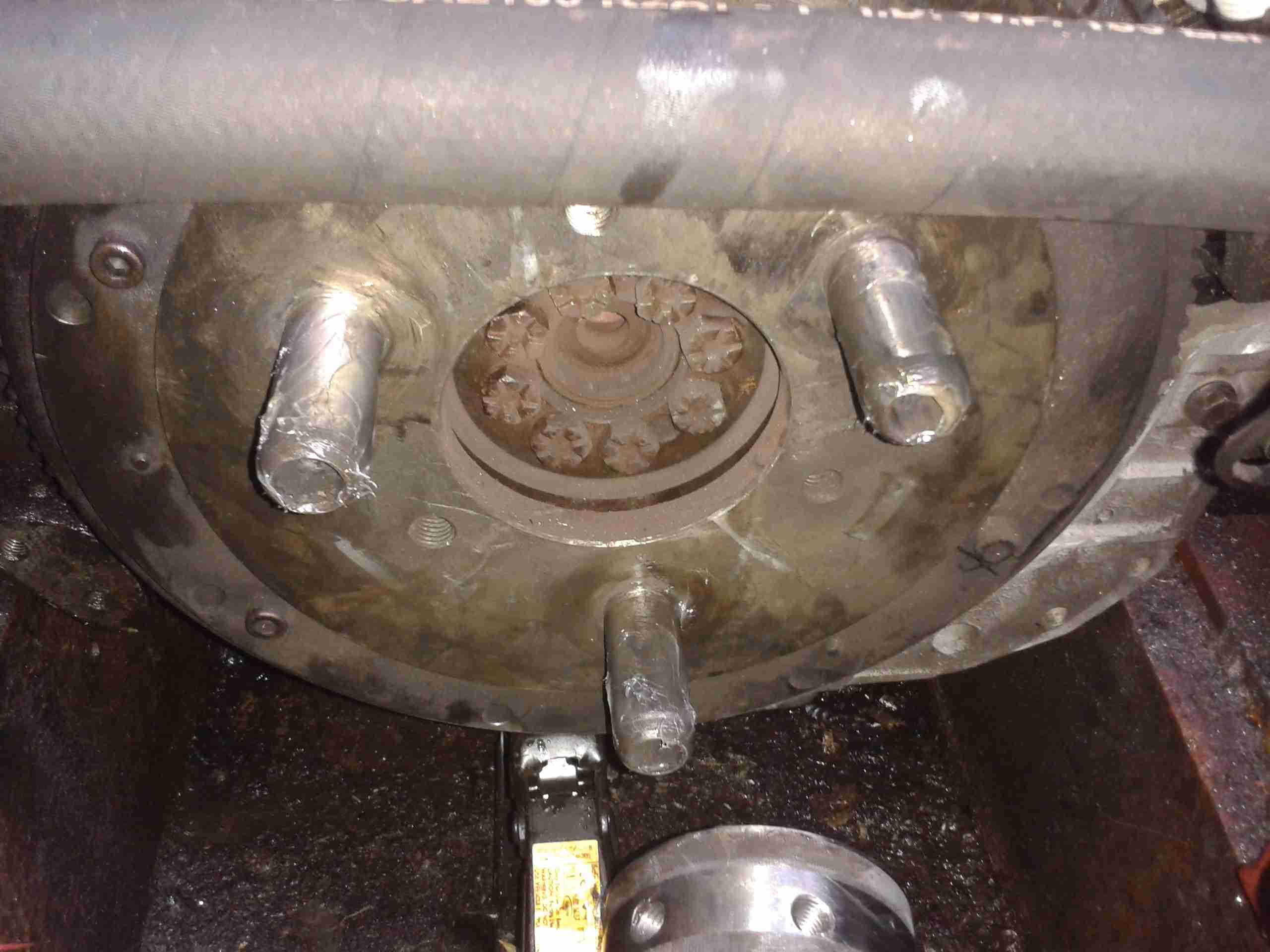
Flywheel
Here’s the engine flywheel, where the rubber coupling normally sits. The mounting pins have been greased ready to accept the rest of the coupling.
Doughnut
Here’s the rubber element mounted on the pins – there’s nothing holding it there in normal operation apart from the mating side of the coupling with the pump.
Unfortunately the weather here in Manchester has prevented us from getting any further – more t0 come when the rain stops!
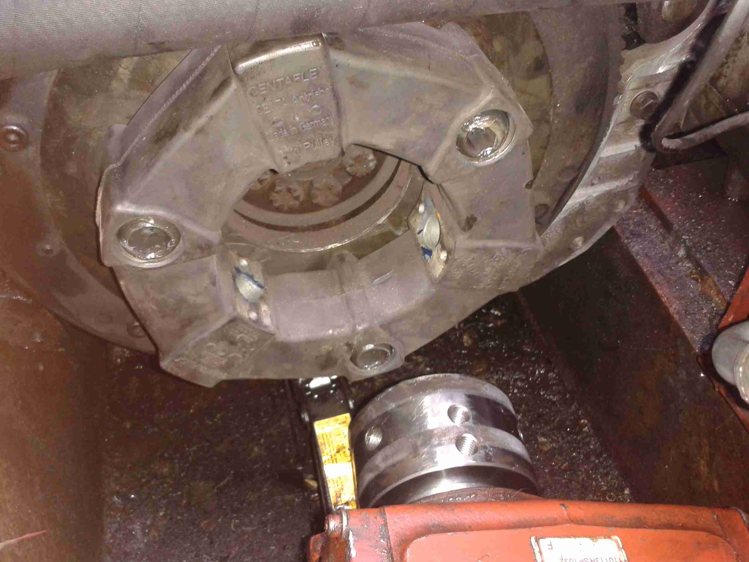
As I have posted about before, the main propulsion system onboard the boat is all hydraulic. To get the drive from the flywheel of the engine to the hydraulic pump stack, a custom drive plate was machined by Centa Transmissions over in Yorkshire, and a Centaflex A coupling was fitted to this.
Centaflex A Coupling
This coupling is a big rubber doughnut, bolted to a centre hub of steel. The steel hub is splined onto the input shaft of the hydraulic pump stack.
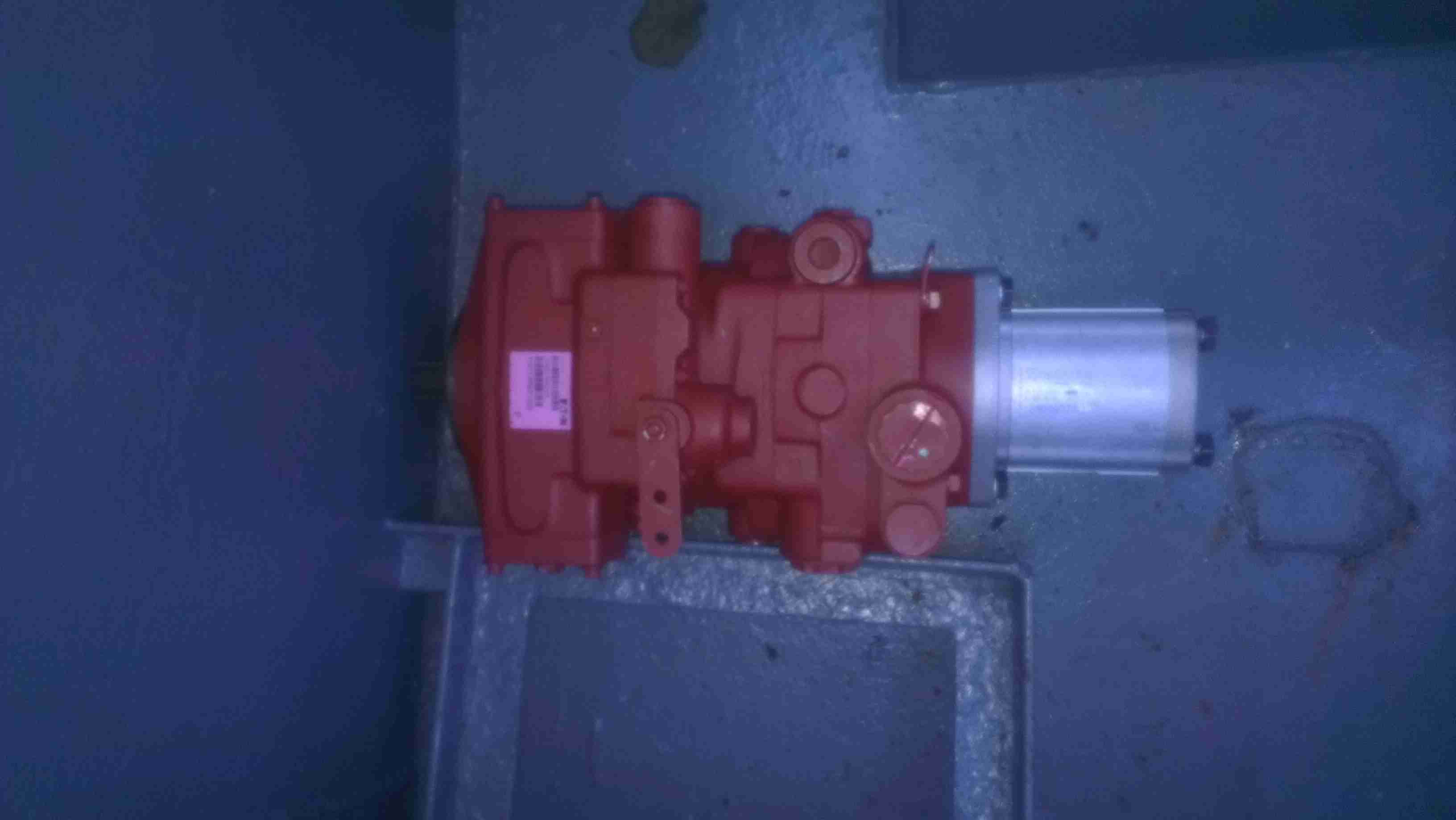
Pump Stack
The problem we’ve had is that to prevent the coupling from riding along the splines in operation, a pair of giant grub screws are provided in the side of the centre steel boss, that compress the splines to lock the device in place. These screws are a nightmare to get tightened down (the engineer from Centa who originally came to survey the system said we’d probably shear some tools off trying).
Because of this, the grub screws have loosened over the last 350-odd hours of running & this has had the effect of totally destroying the splines in the hub.
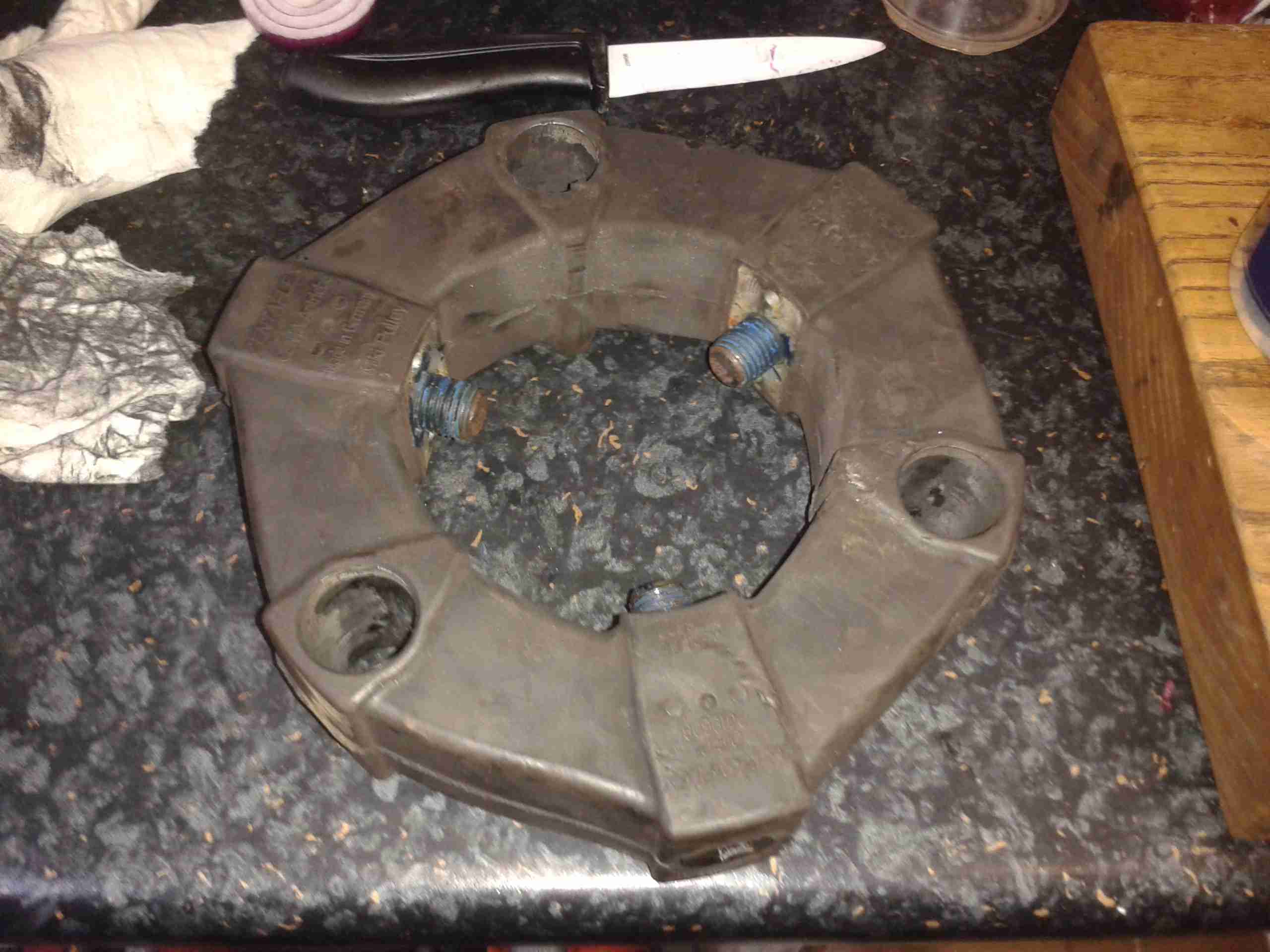
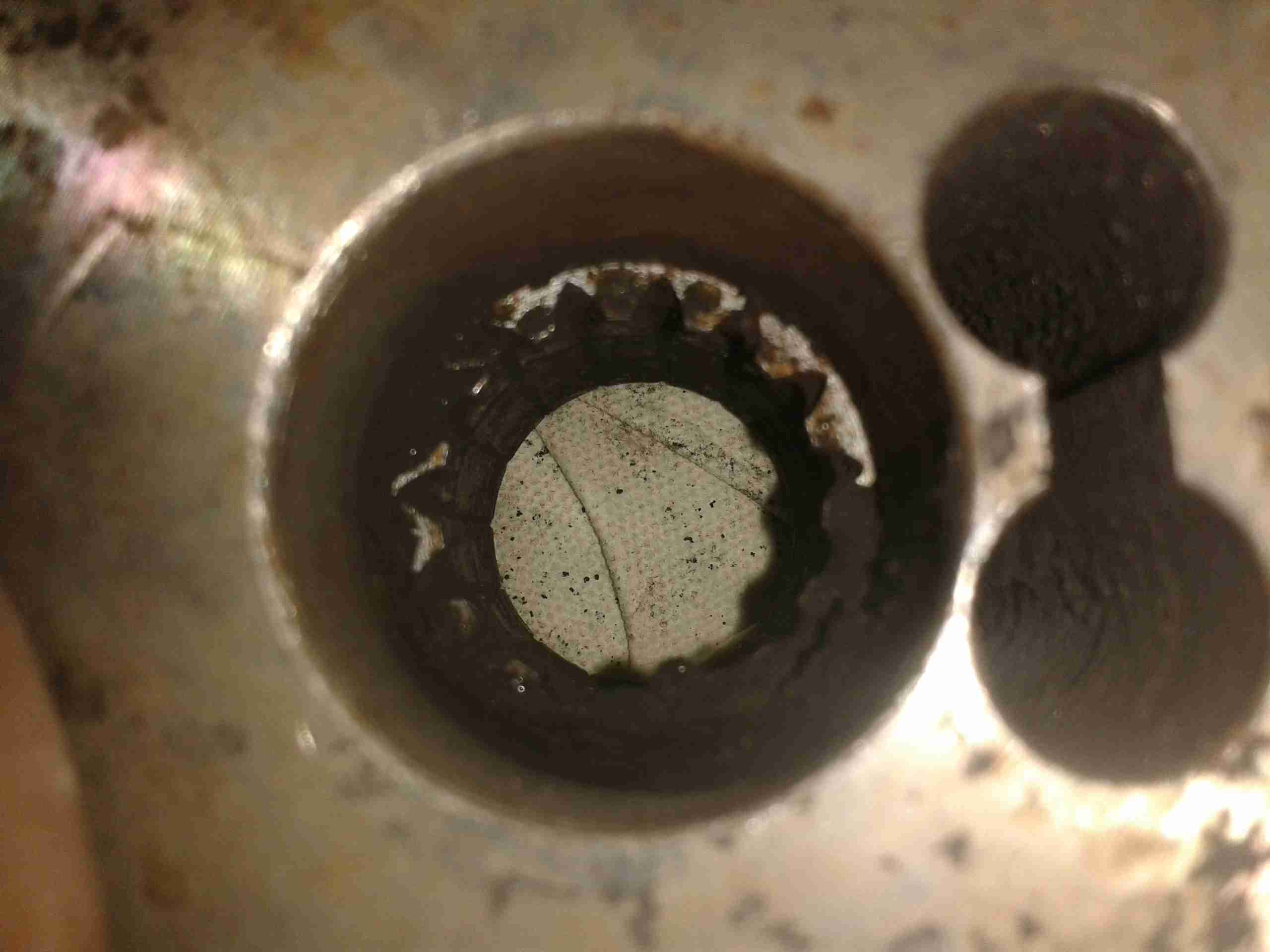
Spline Remains
Here’s the backside of the centre boss, with what remains of the splines, the figure-8 shaped gap on the right is where the securing grub screws deform the steel to lock the coupling into place.
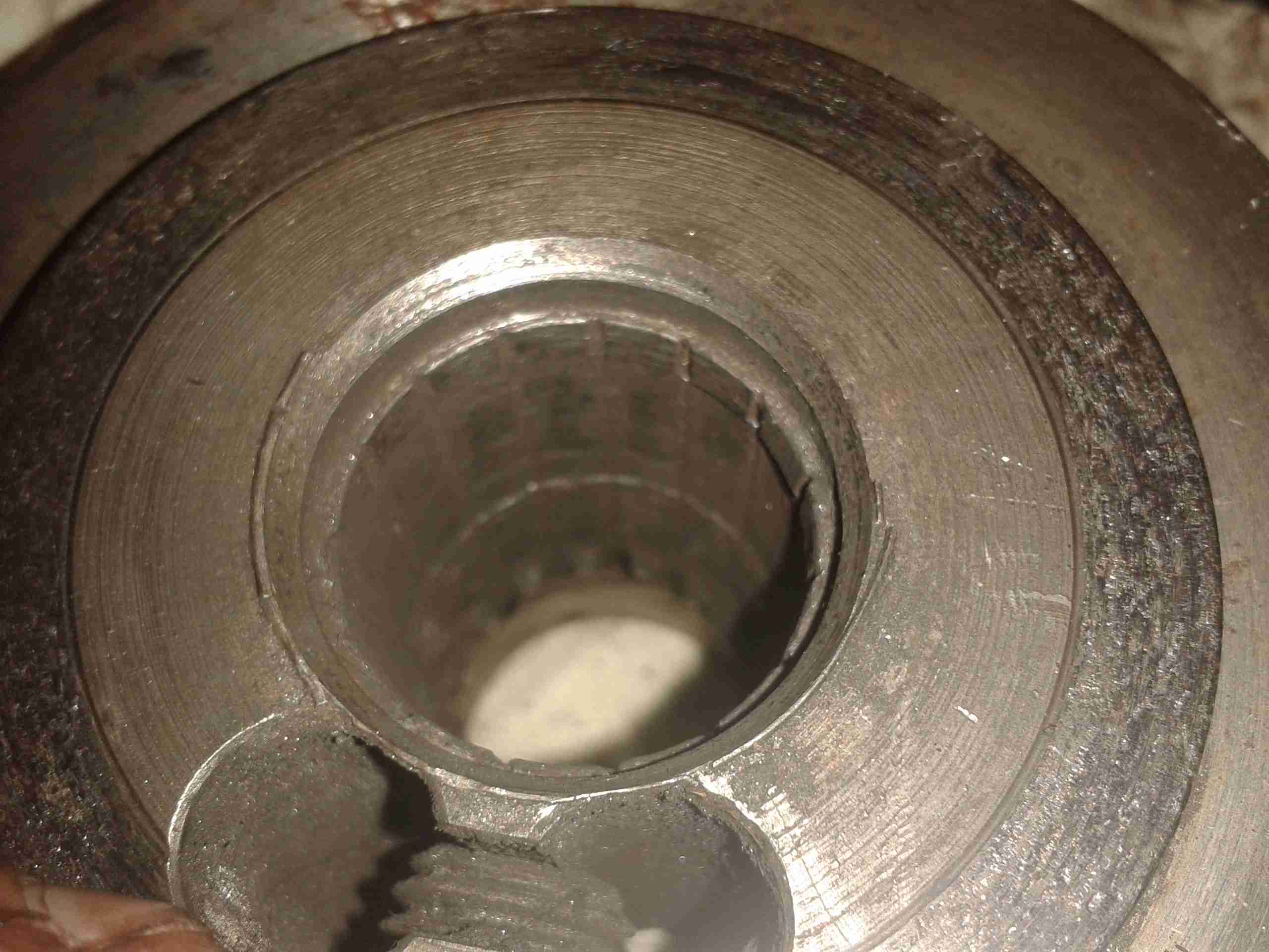
No More Splines
Here’s the other side of the coupling, showing the damage. The splines have effectively been totally removed, as if I’d gone in there with a boring bar on the lathe. Luckily this part isn’t too expensive to replace, and no damage was done to the input shaft of the hydraulic pump stack (Mega ££££). Quite luckily, this damage got to the point of failure while running the engine on the mooring, so it didn’t leave us stranded somewhere without motive power.
This is the teardown of a Zebra P330i plastic card printer, used for creating ID cards, membership cards, employee cards, etc. I got this as a faulty unit, which I will detail later on.
This printer supports printing on plastic cards from 1-30mils thick, using dye sublimation & thermal transfer type printing methods. Interfaces supplied are USB & Ethernet. The unit also has the capability to be fitted with a mag stripe encoder & a smart card encoder, for extra cost.
Print Engine
On the left here is the print engine open, the blue cartridge on the right is a cleaning unit, using an adhesive roller to remove any dirt from the incoming card stock.
This is extremely important on a dye sublimation based printing engine as any dirt on the cards will cause printing problems.
Cards In Feeder
Here on the right is the card feeder unit, stocked with cards. This can take up to 100 cards from the factory.
The blue lever on the left is used to set the card thickness being used, to prevent misfeeds. There is a rubber gate in the intake port of the printer which is moved by this lever to stop any more than a single card from being fed into the print engine at any one time.
Card Feeder Belt
Here is the empty card feeder, showing the rubber conveyor belt. This unit was in fact the problem with the printer, the drive belt from the DC motor under this unit was stripped, preventing the cards from feeding into the printer.
Print Head
Here is a closeup of the print head assembly. The brown/black stripe along the edge is the row of thin-film heating elements. This is a 300DPI head.
Print Station
This is under the print head, the black roller on the left is the platen roller, which supports the card during printing. The spool in the center of the picture is the supply spool for the dye ribbon.
In the front of the black bar in the bottom center, is a two-colour sensor, used to locate the ribbon at the start of the Yellow panel to begin printing.
LCD PCB
Inside the top cover is the indicator LCD, the back of which is pictured right.
This is a 16×1 character LCD from Hantronix. This unit has a parallel interface.
LCD
Front of the LCD, this is white characters on a blue background.
Roller Drive Belts
Here is the cover removed from the printer, showing the drive belts powering the drive rollers. There is an identical arrangement on the other side of the print engine running the other rollers at the input side of the engine.
Mains Filter
Here the back panel has been removed from the entire print engine, complete with the mains input wiring & RFI filtering.
This unit has excellent build quality, just what is to be expected from a £1,200+ piece of industrial equipment.
Main Frame With Motors
The bottom of the print engine, with all the main wiring & PCB removed, showing the main drive motors. The left hand geared motor operates the head lift, the centre motor is a stepper, which operates the main transmission for the cards. The right motor drives the ribbon take up spindle through an O-Ring belt.
Feeder Drive Motor
Card feeder drive motor, this connects to the belt assembly through a timing belt identical to the roller drive system.
All these DC geared motors are 18v DC, of varying torque ratings.
Power Supply
Here is the main power supply, a universal input switch-mode unit, outputting 24v DC at 3.3A.
PSU Label
PSU info. This is obviously an off the shelf unit, manufactured by Hitek. Model number FUEA240.
Print Engine Rear
The PSU has been removed from the back of the print engine, here is shown the remaining mechanical systems of the printer.
Print Engine Components
A further closeup of the print engine mechanical bay, the main stepper motor is bottom centre, driving the brass flywheel through another timing belt drive. The O-Ring drive on the right is for the ribbon take up reel, with the final motor driving the plastic cam on the left to raise/lower the print head assembly.
The brass disc at the top is connected through a friction clutch to the ribbon supply reel, which provides tension to keep it taut. The slots in the disc are to sense the speed of the ribbon during printing, which allows the printer to tell if there is no ribbon present or if it has broken.
RFID PCB
Here is a further closeup, showing the RFID PCB behind the main transmission. This allows the printer to identify the ribbon fitted as a colour or monochrome.
The antenna is under the brass interrupter disc on the left.
I/O Daughterboard
The I/O daughterboard connects to the main CPU board & interfaces all the motors & sensors in the printer.
Main PCB
Here is the main CPU board, which contains all the logic & processing power in the printer.
CPU
Main CPU. This is a Freescale Semiconductor part, model number MCF5206FT33A, a ColdFire based 32-bit CPU. Also the system ROM & RAM can be seen on the right hand side of this picture.
Ethernet Interface
Bottom of the Ethernet interface card, this clearly has it’s own RAM, ROM & FPGA. This is due to this component being a full Parallel interface print server.
Ethernet Interface Top
Top of the PCB, showing the main processor of the print server. This has a ferrite sheet glued to the top, for interference protection.
Tip Jar
If you’ve found my content useful, please consider leaving a donation by clicking the Tip Jar below!
All collected funds go towards new content & the costs of keeping the server online.