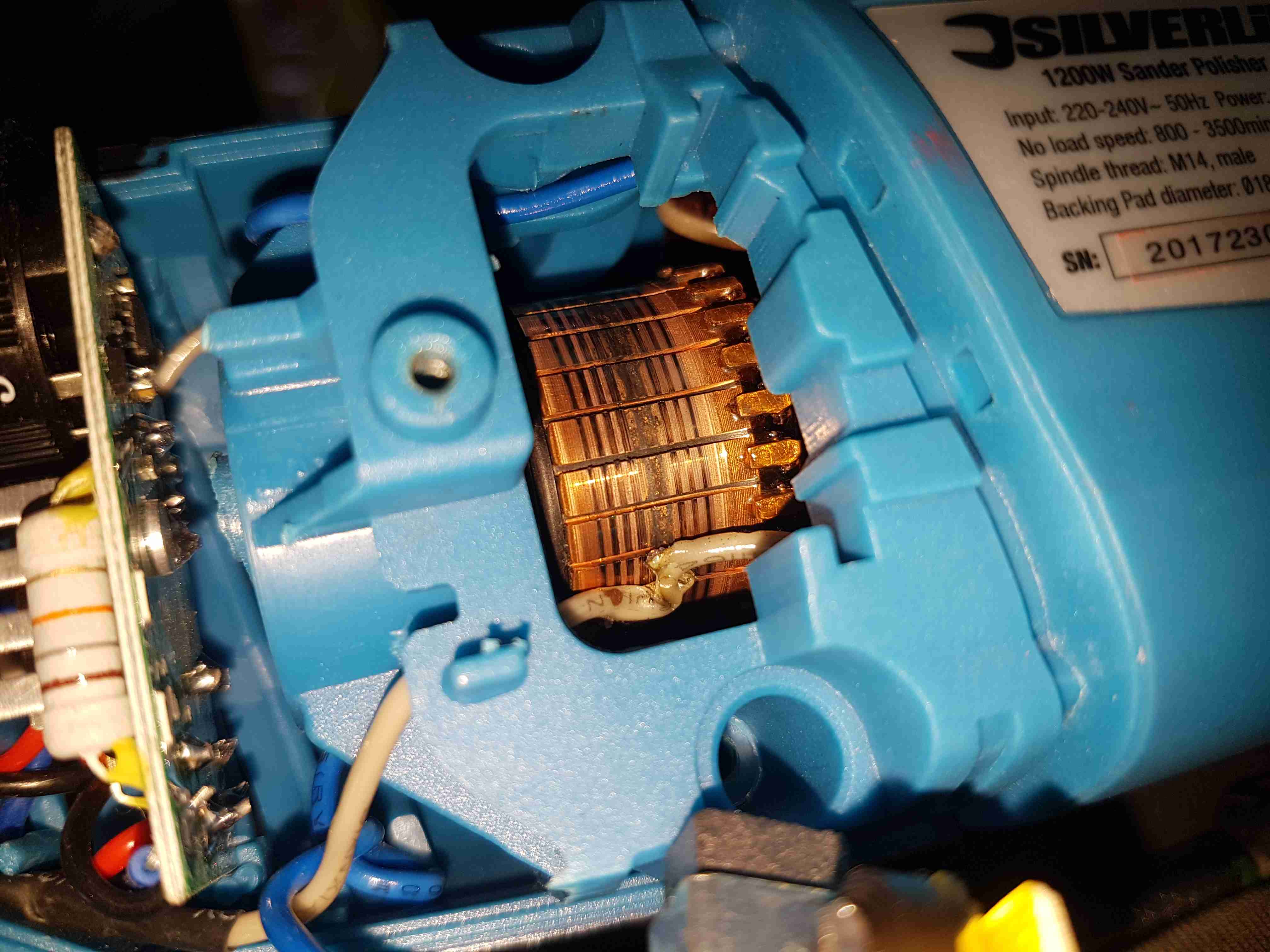
Since I seem to be the local go-to for any dead electrical equipment, this brand-new Silverline polisher has landed on my desk. Purchased cheap from an auction this was dead on arrival. Checking the fuse revealed nothing suspect, so a quick teardown to find the fault was required.
Above is a photo of the commutator with the brush holder removed, and the source of the issue. The connection onto the field winding of the universal motor has been left unsecured, as a result it’s managed to move into contact with the commutator.
This has done a pretty good job of chewing it’s way through the wire entirely. There is some minor damage to the commutator segments, but it’s still smooth, and shouldn’t damage the brushes.
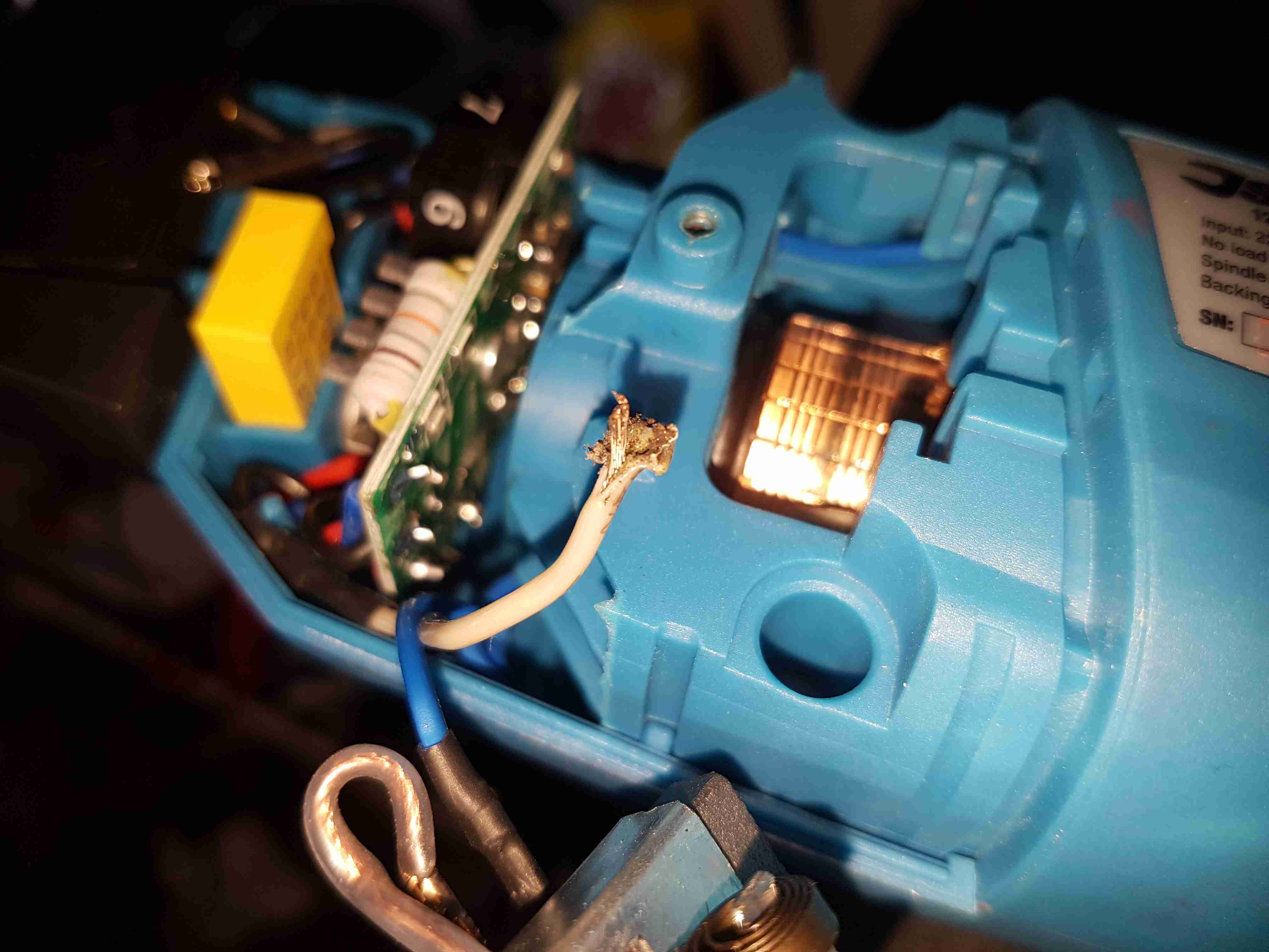
Chewed Wire
A quick pull on what’s left of the wire reveals the extent of the problem. It’s entirely burned through! Unfortunately the stator assembly with the field windings is pressed into the plastic housing, so it’s not removable. An in-place solder joint was required to the very short remains of the wire inside the housing. Once this was done the polisher sprang to life immediately, with no other damage.
This unit probably ended up at an auction as a factory reject, or a customer return to a retail outlet. If the latter, I would seriously question the quality control procedures of Silverline tools. 😉
Since I’ve been working on the backend servers a lot over the past few days, I’ve decided it was time to get some broken things on the blog fixed.
Firstly, the radiation monitor graphs. Originally I was using a Raspberry Pi to grab the data from the local monitor, and that was connecting via FTP to the server over in the datacentre to push it’s graph images. Since the server is now on the same local network as the monitor, there’s no need to faff about with FTP servers, so I’ve rejigged things with some perl scripts from cristianst85 over on GitHub, running on the web server itself.
I deviated from the suggested place to put the scripts on the server & opted to store everything within the Experimental Engineering hosting space, so it gets backed up at the same time as everything else on a nightly basis.
powered by Advanced iFrame
This is also accessible from the menu at top left, the script pulls data from the monitor & updates the images every 60 seconds via a cron job.
I’ve removed a couple of dead pages from the blog system, along with some backend tidying of the filesystem. Over the years things have gotten quite messy behind the scenes. This blog is actually getting quite large on disk, I’ve hit the 15GB mark, not including the database!
Caching is enabled for all posts on the blog now, this should help speed things up for repeat visitors, but as most of my content is (large) image based, this might be of limited help. I’m currently tuning the MySQL server for the load conditions, but this takes time, as every time I change some configuration settings I have to watch how things go for a few days, before tweaking some more.
Server Control Panels – More Of The Same
Sorry Sentora. I tried, and failed to convert over to using it as my new server control panel. Unfortunately it just doesn’t give me the same level of control over my systems, so I’ll be sticking with Virtualmin for the foreseeable future. Sentora stores everything in, (to me at least), very odd places under /var/ and gave me some odd results with “www.” versions of websites – some www. hosts would work fine, others wouldn’t at all & just redirect to the Sentora login interface instead. This wasn’t consistient between hosting accounts either, and since I didn’t have much time to get the migration underway, this problem was the main nail in the coffin.
Just storing everything under the sun in /var/ makes life a bit more awkward with the base CentOS install, as it allocates very little space to / by default, (no separate /var partition in default CentOS), giving most of the disk space to /home. Virtualmin on the other hand, stores website public files & Maildirs under /home, saving /var for MySQL databases & misc stuff.
The backup system provided is also utterly useless, there’s no restore function at all, and just piles everything in the account into a single archive. By comparison, Virtualmin has a very comprehensive backup system built in, that supports total automation of the process, along with full automatic restore functionality for when it’s needed.
Sentora did have some good points though:
It handled E-Mail logins & mail filters much more gracefully than Virtualmin does, and comes with Roundcube already built into the interface ready to use. With Virtualmin the options are to use the Usermin side of the system for E-Mail, which I find utterly awful to use, or install a webmail client under one of the hosted domains (my personal choice).
Mail filtering is taken care of with Sieve under Sentora, while Procmail does the job under Virtualmin.
Sentora does have a nicer, simpler, more friendly interface, but it hides most of the low-level system stuff away, while under Virtualmin *everything* on the system is accessible, and it provides control interfaces for all the common server daemons.
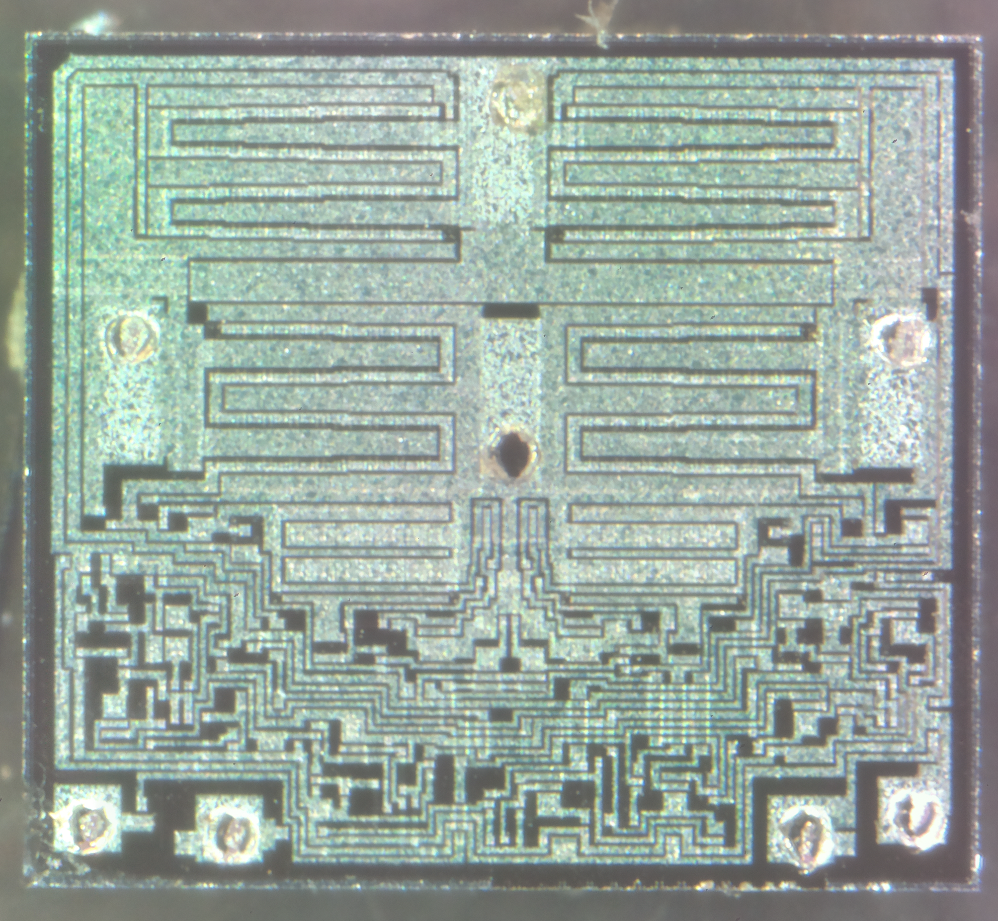
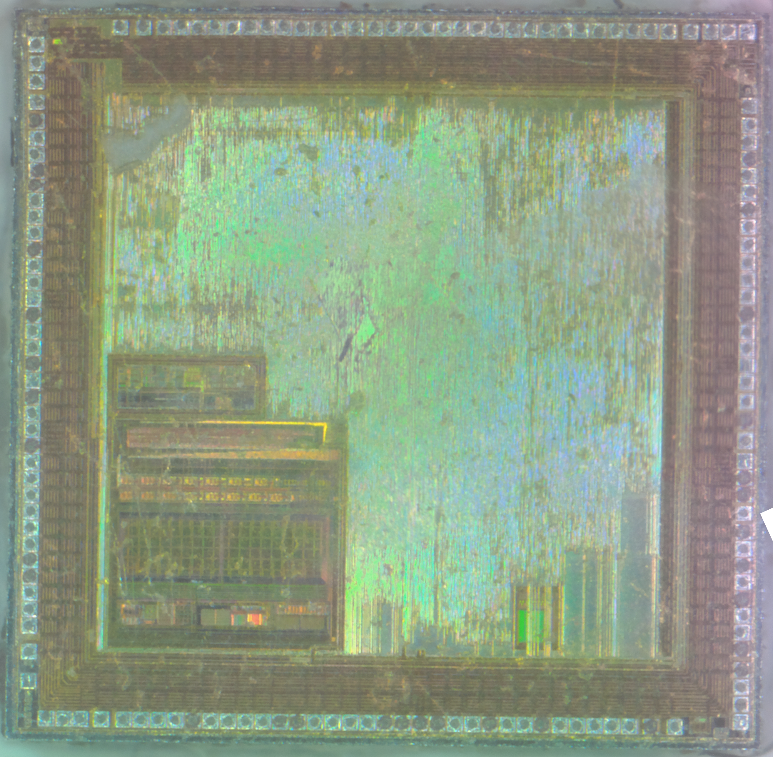
Here’s a jellybean chip – a DC motor driver. This device has all the logic to drive a small motor, such as that used to drive the tray of a CD drive in both directions. The control logic is at the bottom of the die, while the main power transistors are at the top, in H-Bridge formation.
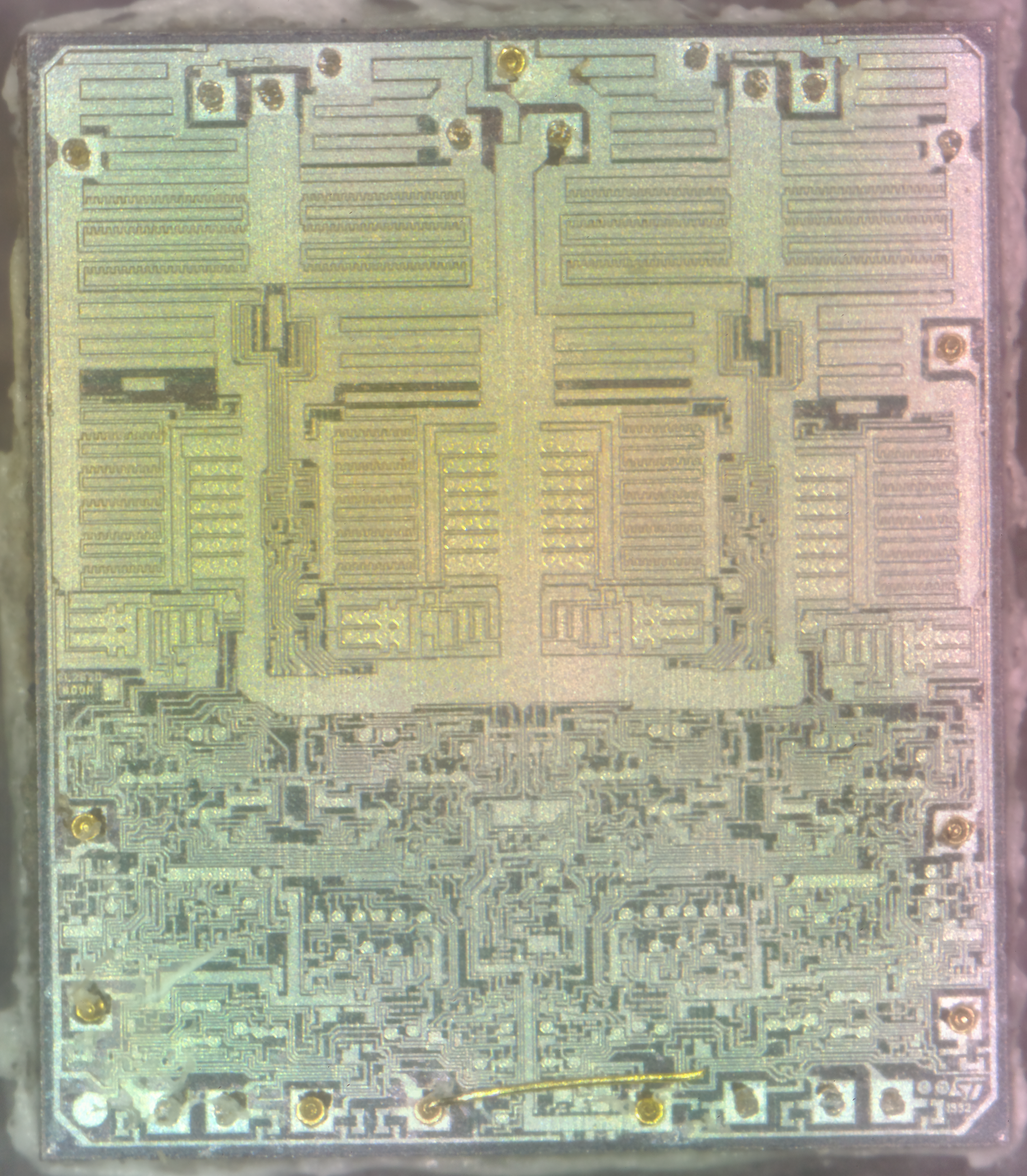
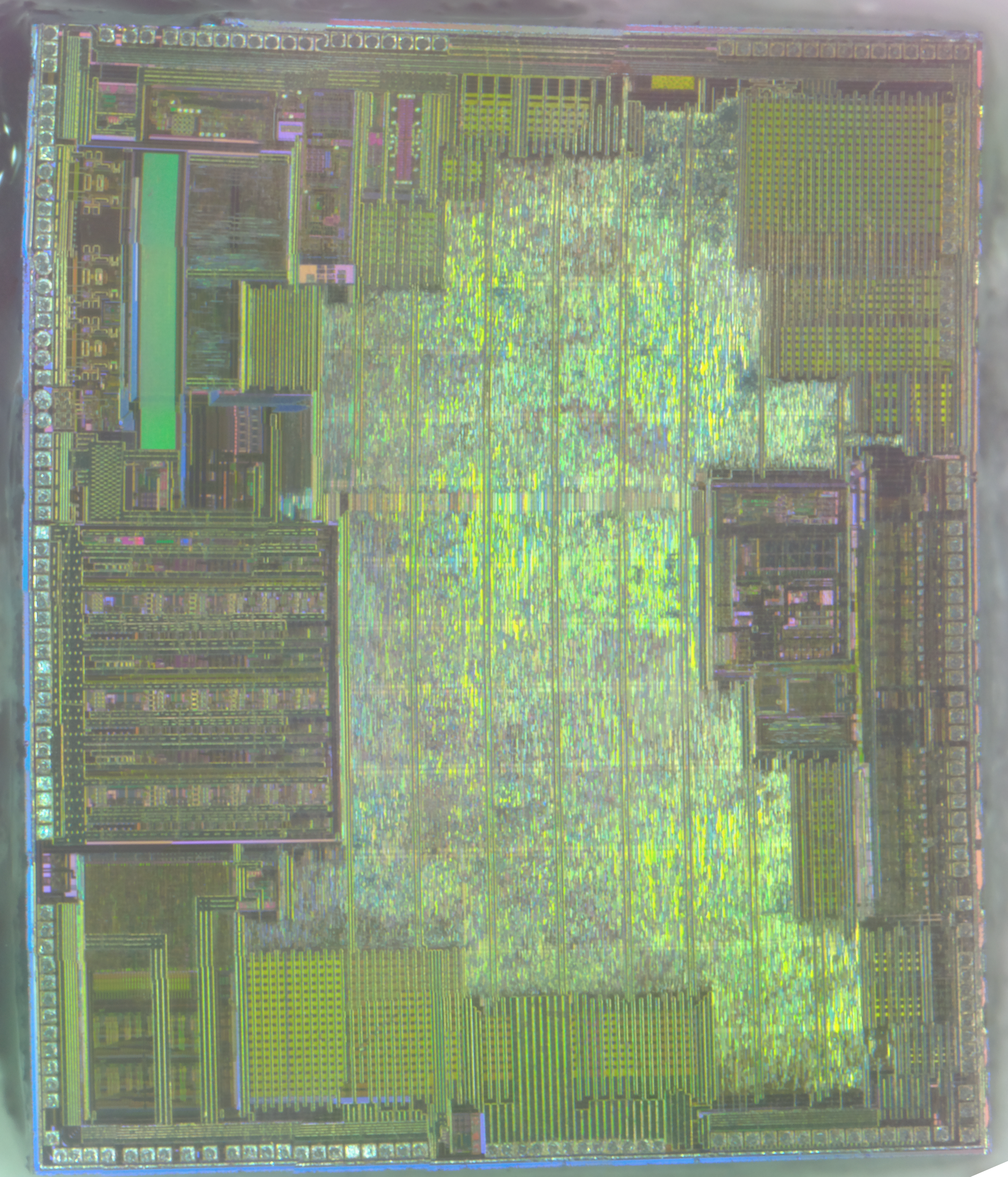
Another decapped IC! This one is an ST L6219 750mA stepper motor driver. The control logic is all at the bottom of the die, with the high current H-Bridge transistors at the top.
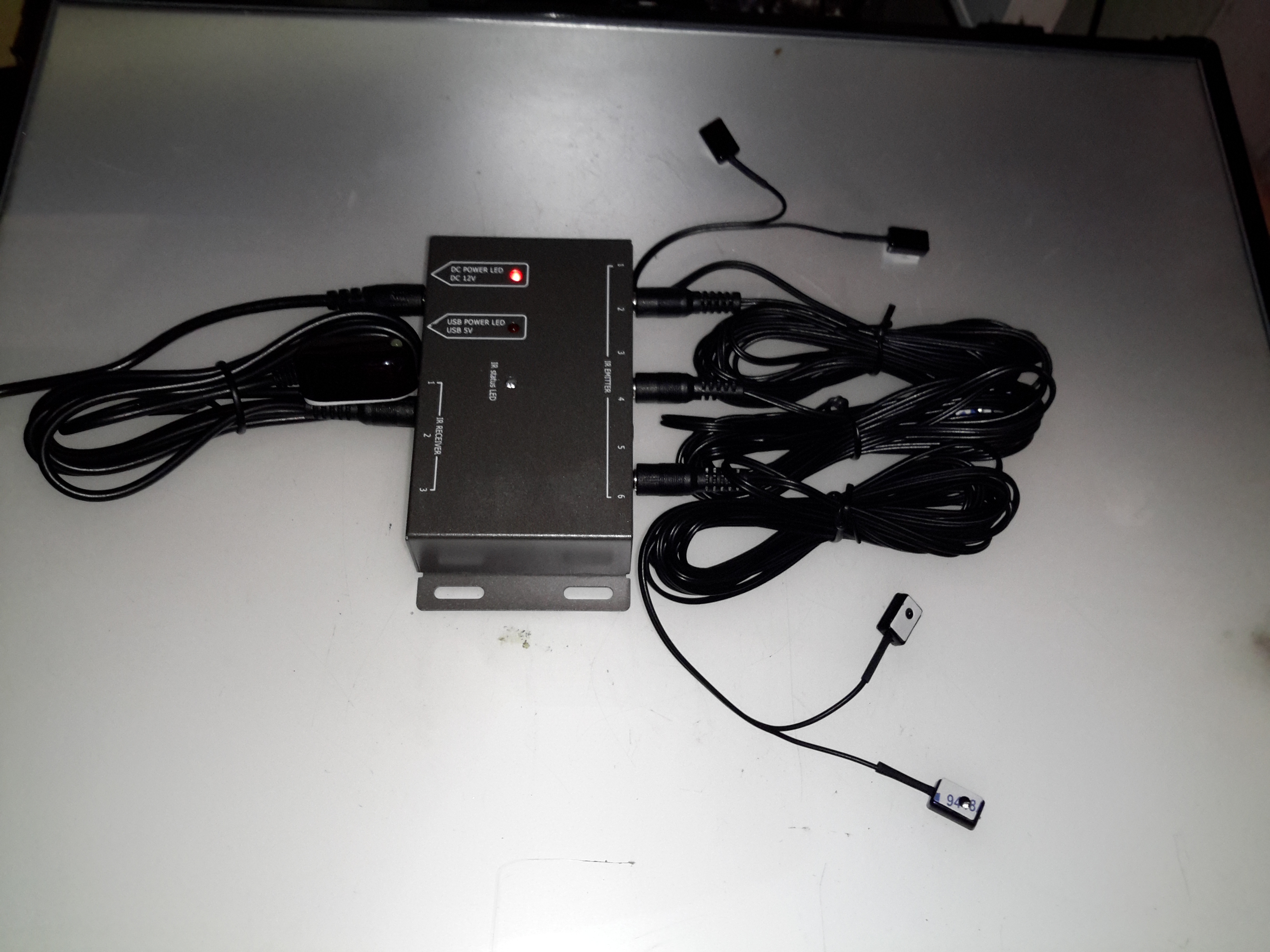
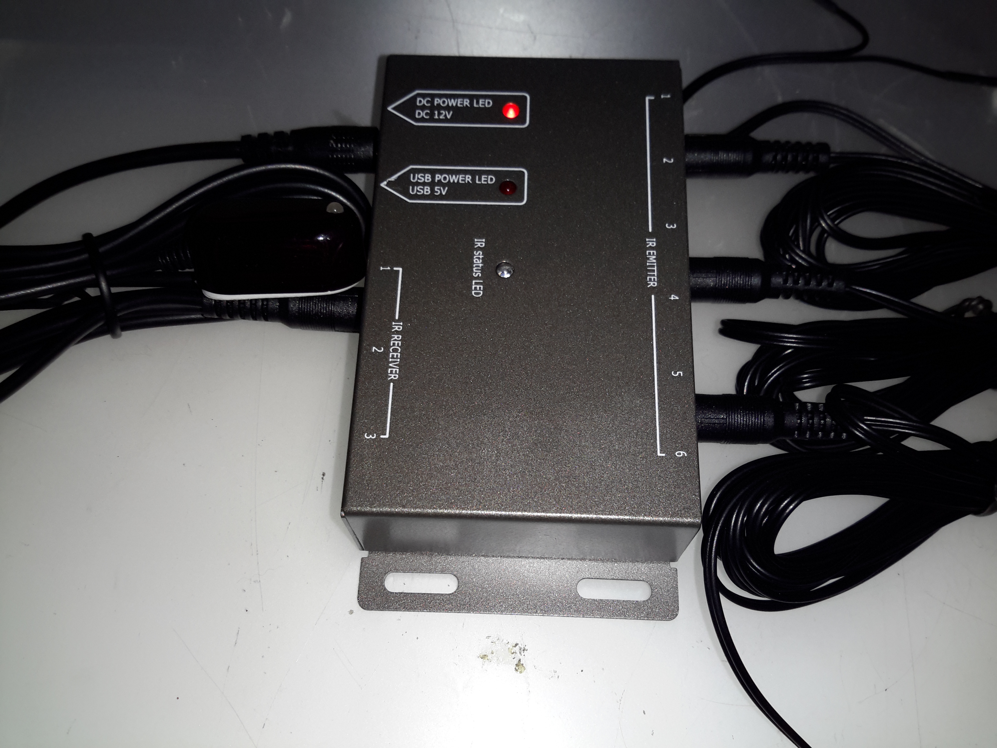
Here’s another random gadget for teardown, this time an IR remote control repeater module. These would be used where you need to operate a DVD player, set top box, etc in another room from the TV that you happen to be watching. An IR receiver sends it’s signal down to the repeater box, which then drives IR LEDs to repeat the signal.
Repeater Module
Not much to day about the exterior of this module, the IR input is on the left, up to 3 receivers can be connected. The outputs are on the right, up to 6 repeater LEDs can be plugged in. Connections are done through standard 3.5mm jacks.
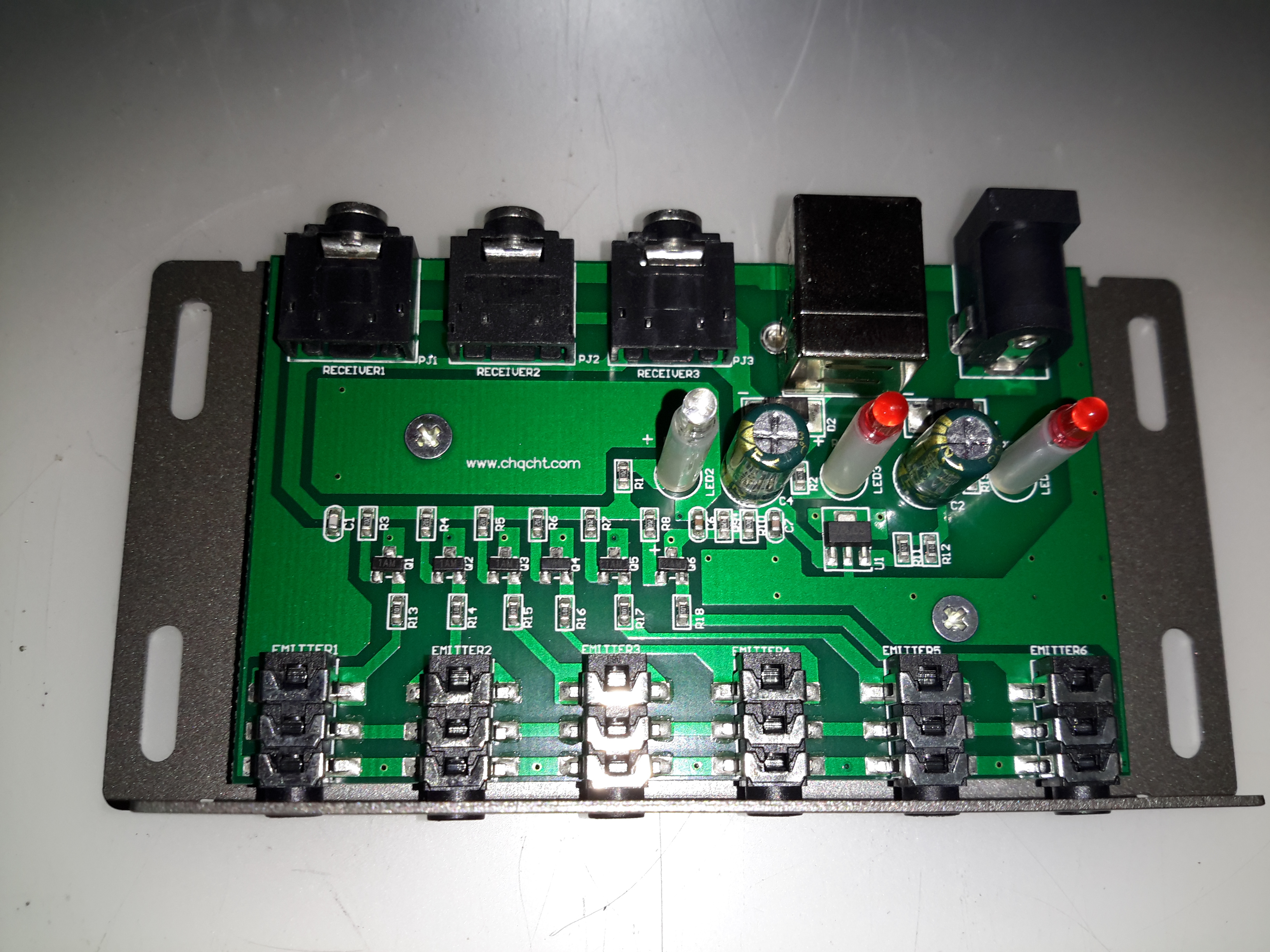
Repeater PCB
Not much inside this one at all, there are 6 transistors which each drive an LED output. This “dumb” configuration keeps things very simple, no signal processing has to be done. Power is either provided by a 12v input, which is fed into a 7805 linear regulator, or direct from USB.
Effects of Magnetic Fields on He-Ne Laser Operation
If you open the case on a higher power (and longer) He-Ne laser head or one that is designed with an emphasis on precision and stability, you may find a series of magnets or electromagnetic coils in various locations in close proximity to the He-Ne tube. They may be distributed along its length or bunched at one end; with alternating or opposing N and S poles, or a coaxial arrangement; and of various sizes, styles, and strengths.
Magnets may be incorporated in He-Ne lasers for several reasons including the suppression of IR spectral lines to improve efficiency (such as it is!) and to boost power at visible wavelengths, to control its polarization, and to split the optical frequency into two closely spaced components. There are no doubt other uses as well.
The basic mechanism for the interaction of emitted light and magnetic fields is something called the ‘Zeeman Effect’ or ‘Zeeman Splitting’. The following brief description is from the “CRC Handbook of Chemistry and Physics”:
“The splitting of a spectrum line into several symmetrically disposed components, which occurs when the source of light is placed in a strong magnetic field. The components are polarized, the directions of polarization and the appearance of the effect depending on the direction from which the source is viewed relative to the lines of force.”
Magnetic fields may affect the behaviour of He-Ne tubes in several ways:
He-Ne tubes with long discharge paths will tend to amplify the (generally unwanted) IR wavelengths (probably the one at 3.39µm which is one of the strongest, if not the strongest of all lines) at the expense of the visible ones. The purpose of these magnets is to suppress spectral lines that do not contribute to the desired lasing wavelength (usually the visible red 632.8nm for these long tubes). As a result of the Zeeman Effect, if a gas radiates in a magnetic field, most of its spectral lines are split into 2 or sometimes more components. The magnitude of the separation depends on the strength of the magnetic field and as a result, if the field is also non-uniform, the spectral lines are broadened as well because light emitted at different locations will see an unequal magnetic field. These ‘fuzzed out’ lines cannot participate in stimulated emission as efficiently as nice narrow lines and therefore will not drain the upper energy states for use by the desired lines. The magnitude of the Zeeman splitting effect is also wavelength dependent and therefore can be used to control the gain of selected spectral lines (long ones are apparently affected more than short ones on a percentage basis).The Doppler-broadened gain bandwidth of neon is inversely related to wavelength. At 632.8nm (red) it is around 1.5 to 1.6 GHz; at 3,391nm (the troublesome IR line), it is only around 310MHz. A magnetic field that varies spatially along the tube will split and move the gain curves at all wavelengths equally by varying amounts depending on position. However, a, say, 100 or 200MHz split and shift of the gain curve for the 632.8nm red transition won’t have much effect, but it will effectively disrupt lasing for the 3,391nm IR transition.Without the use of magnets, the very strong neon IR line at 3.39µm would compete with (and possibly dominate over) the desired visible line (at 632.8nm) stealing power from the discharge that would otherwise contribute to simulated emission at 632.8 nm. However, the IR isn’t wanted (and therefore will not be amplified since the mirrors are not particularly reflective at IR wavelengths anyhow). Since the 3.39nm wavelength is more than 5 times longer than the 632.8 nm red line, it is affected to a much greater extent by the magnetic field and overall gain and power output at 632.8nm may be increased dramatically (25 percent or more). The magnets may be required to obtain any (visible) output beam at all with some He-Ne tubes (though this is not common).
The typical higher power Spectra-Physics He-Ne laser will have relatively low strength magnets (e.g., like those used to stick notes to your fridge) placed at every available location along the exposed bore along the sides of the L-shaped resonator frame. They will alternate N and S poles pointing toward the bore. Interestingly, on some high mileage tubes, brown crud (which might be material sputtered off the anode) may collect inside the bore – but only at locations of one field polarity (N or S, whichever would tend to deflect a positive ion stream into the wall). The crud itself doesn’t really affect anything but is an indication of long use. And on average, tubes with a lot of brown crud may be harder to start, and require a higher voltage to run, and have lower output power.
I do not know how to determine if and when such magnets are needed for long high power He-Ne tubes where they are not part of an existing laser head. My guess is that the original or intended positions, orientations, and strengths, of the magnets were determined experimentally by trial and error or from a recipe passed down from generation to generation, and not through the use of some unusually complex convoluted obscure theory. 🙂
The only thing I can suggest other than contacting the manufacturer (like any manufacturer now cares about and supports He-Ne lasers at all!) is to very carefully experiment with placing magnets of various sizes and strengths at strategic locations (or a half dozen such locations) to determine if beam power at the desired wavelength is affected. Just take care to avoid smashing your flesh or the He-Ne tube when playing with powerful magnets. Though the magnets used in large-frame He-Ne lasers with exposed bores aren’t particularly powerful, to produce the same effective field strength at the central bore of an internal mirror He-Ne tube may require somewhat stronger ones, though even these needn’t be the flesh squashing variety. And, magnets that are very strong may affect other characteristics of the laser including polarization, and starting and running voltage. Enclosing the He-Ne tube in a protective rigid sleeve (e.g., PVC or aluminium) would reduce the risk of the latter disaster, at least. 🙂 If there is going to be any significant improvement, almost any arrangement of 1 or 2 magnets should show some effect.
There may be an immediate effect when adding or moving a magnet. However, to really determine the overall improvement in (visible) output power and any reduction in the variation of output power with mode sweep, the laser should be allowed to go through several mode sweep cycles for 3.39 µm. These will be about 5.4 times the length of the mode sweep for 632.8 nm.
CAUTION: For soft-seal laser tubes in less than excellent health (i.e., which may have gas contamination), changing the magnet configuration near the cathode may result in a slow decline in output power (over several hours) which may or may not recover. I have only observed this behaviour with a single REO one-Brewster tube, but there seems to be no other explanation for the slow decline to about half the original power, and then subsequent slow recovery with extended run time after the magnets were removed entirely. Possibly simply leaving the magnets in the new configuration would have eventually resulted in power recovery, but at the time the trend was not encouraging.
“They’ve pretty much nailed the 3.39 micron problem on red He-Ne tubes these days so magnets really aren’t needed on them. Even the new green tubes don’t have much of a problem – especially since the optic suppliers have perfected the mirror coatings. All of the good green mirrors are now done with Ion Beam Sputtering (IBS), as opposed to run-of-the-mill E-Beam stuff.However, you’ll probably see a benefit from magnets to suppress the 3.39µm line on the older He-Ne tubes.”
While most inexpensive He-Ne tubes that produce linearly polarized light do so because of an internal Brewster plate and lasers with external mirrors have Brewster windows on the ends of the plasma tube, it is also possible to affect the polarization of the beam with strong magnets again using the Zeeman Effect.Where the capillary of the plasma tube is exposed as with many older lasers, and the magnets can be placed in close proximity to the bore, their strength can be much lower. A few commercial lasers (like the Spectra-Physics model 132) offered a polarization option which adds a magnet assembly alongside the tube. In this case, what is required is a uniform or mostly uniform field of the appropriate orientation rather than one that varies as for IR spectral line suppression though both of these could be probably be combined. However, the polarization purity with this approach never came anywhere close to that using a simple Brewster window or plate, found in all modern polarized He-Ne lasers.Also see the section: Unrandomizing the Polarization of a Randomly Polarized HeNe Tube.
Two-frequency He-Ne lasers are used in precision interferometers for making measurements to nanometer accuracy. With these, the Zeeman effect is exploited to split the output of a single frequency He-Ne laser into a pair of closely spaced optical frequencies so that a difference or “split” frequency can be obtained using a fast photodiode. The most common are axial Zeeman lasers that use a powerful magnetic field oriented along the axis of the tube. For these, the “split” frequency is typically between 1.5 and 7.5 MHz (though it could be much lower but not much higher). Transverse Zeeman lasers use a moderate strength field oriented across the tube and have split frequencies in the 100s of kHz range. To stabilize these lasers, either a heater or piezo element is provided to precisely control cavity length.
In principle, varying fields from electromagnets could be used for intensity, polarization, and frequency modulation. I do not know whether any commercial He-Ne lasers have been implemented in this manner.
But if magnets were not originally present, the only situation where adding some may make sense is for older longer or “other colour” He-Ne tubes where a series of weak magnets may actually boost output power by 10 to 25 percent or more. On the other hand, most non-Zeeman stabilized He-Ne lasers do NOT like magnets at all. Even a relatively weak stray magnetic field from nearby equipment may result in a significant change in behaviour. However, unless ferrous metals are used in the laser’s construction, any change will likely not be permanent.
Typical Magnet Configurations
Here are examples of some of the common arrangements of magnets that you may come across. In addition to those shown, magnets may be present along only one side of the tube (probably underneath and partially hidden) or in some other peculiar locations. I suspect that for many commercial He-Ne lasers, the exact shape, strength, number, position, orientation, and distribution of the magnets was largely determined experimentally. In other words, some poor engineer was given a bare He-Ne tube, a pile of assorted magnets, a roll of duct tape, and a lump of modelling clay, and asked to optimize some aspect(s) of the laser’s performance. 🙂
Transverse (varying field) – These will most likely be permanent magnets in pairs, probably several sets.Polarity may alternate with North and South poles facing each other across the tube forming a ‘wiggler’ so named since such a they will tend to deflect the ionized discharge back and forth though there may be no visible effects in the confines of the capillary:
                   N      S      N      S      N      S      N
             ||===================================================||
             ||======. .=================================. .======||
                   S |||  N      S      N      S      N  |_| S
                     '|'                                 '|'
For some including the Spectra-Physics 120, 124, 125, and 127, the magnets are actually below and on one side. The objective is usually IR (3.39µm) suppression and the magnets are generally relatively weak (refrigerator note holding strength). Alternatively, North and South poles may face each other:
                   N      S      N      S      N      S      N
             ||===================================================||
             ||======. .=================================. .======||
                   N |||  S      N      S      N      S  |_| N
                     '|'                                 '|'
With either of these configurations, after long hours of operation, there may be very pronounced brown deposits inside the bore that correlate with the pole positions.
Transverse (uniform field). Here, the objective is to achieve a constant field throughout the entire discharge:
                   N      N      N      N      N      N      N
             ||===================================================||
             ||======. .=================================. .======||
                   S |||  S      S      S      S      S  |_| S
                     '|'                                 '|'
This configuration is found in two very different situations. Strong magnets were used in laser like the Spectra-Physics 132P to polarize the beam. Weaker magnets are used in transverse Zeeman two-frequency He-Ne lasers.
Axial – These will most likely be permanent magnet toroids (similar to magnetron magnets), though an electromagnetic coil (possibly with adjustable or selectable field strength) could also be used. Thus, the North and South poles will be directed along the tube axis:
                        +--+      +--+      +--+      +--+
                      N |  | S  N |  | S  N |  | S  N |  | S
                        +--+      +--+      +--+      +--+
            ||======================================================||
            ||====. .========================================. .====||
                  |||   +--+      +--+      +--+      +--+   |_|
                  '|' N |  | S  N |  | S  N |  | S  N |  | S '|'
                        +--+      +--+      +--+      +--+
Other axial configurations with opposing poles or radially oriented poles may also be used or there may be a single long solenoid type of coil or cylindrical permanent magnet as for a two-frequency laser interferometer.
Going through eBay recently looking for parts for a couple of CRT-based projects, I came across these DC-DC converters.
Apparently rated from 45-390v DC output at 200mA, these should be ideal for driving some of the electrodes (focus, screen, grid) in a CRT.
Above is the top of the board, input voltage header on the left, output voltage adjust in the centre & output voltage header on the right.
This module has a mini-automotive fuse, at 10A for input protection.
On the heatsink is mounted the main switching MOSFET, a RU7088R from Ruichips. This FET is fairly heavily rated at 70v 80A, with 6.5mΩ on-resistance.
PCB Bottom
The bottom of the board has the control components, with a pair of ICs. Unfortunately the numbers have been scrubbed off, so no identification here. The output from the transformer is rectified with a single large SMD diode on the left side of the board.
There’s also plenty of isolation gap between the HV output trace & the low voltage logic side of the circuit, the two being bridged only by a resistive divider for output voltage measurement.
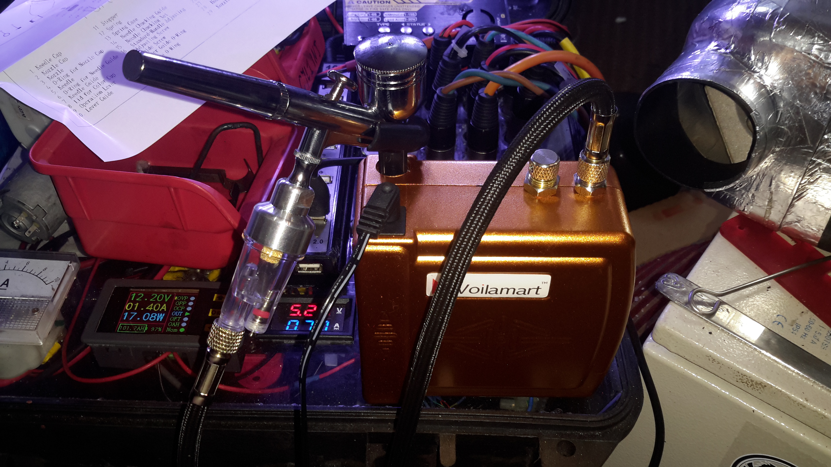
For my latest project, I needed an easier way to paint without messing about with brushes, and the associated marks they leave in a paint job. eBay provided me with a cheap airbrush & compressor.
Airbrush Kit
For less than £30, this kit doens’t look so bad. I’ve never used an airbrush before, but I’ve had no problems with this as yet spraying both water based paints & solvent based paints.
Compressor
Here’s the compressor itself, this runs on 12v & has an output pressure of 1.5 Bar, which is supposed to be adjustable.
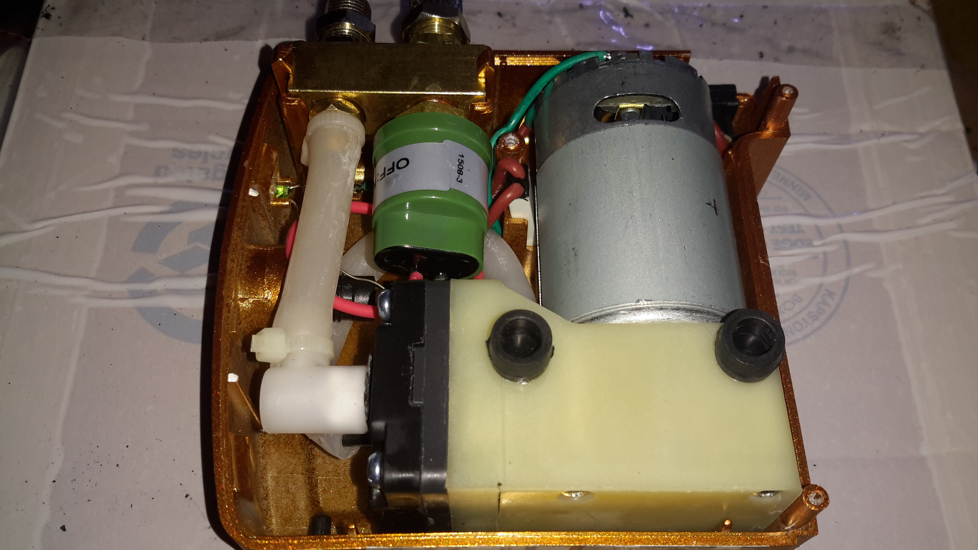
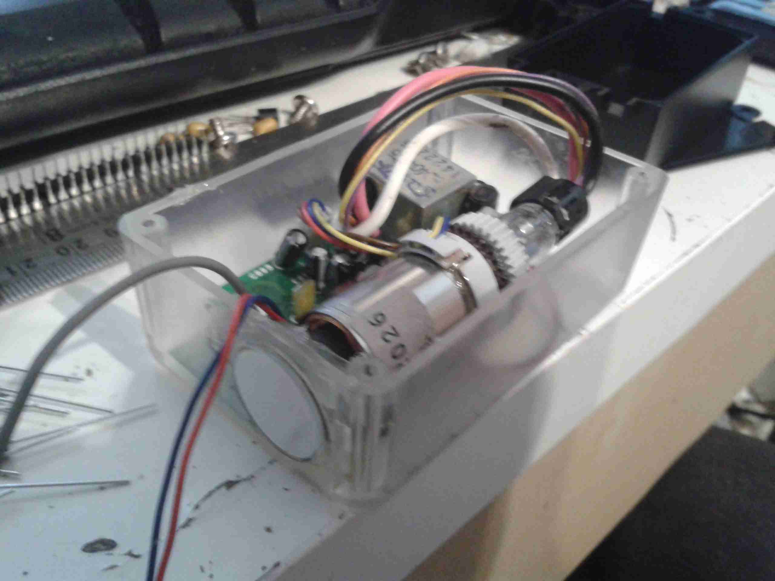
Compressor Internals
Removing a couple of screws reveals the internal components. Nothing much unusual here, a DC diaphragm pump, pressure switch & outlet fittings. There’s also a thermal cutout fitted next to the motor for protection.
The pressure switch attached to the manifold trips at 1.5Bar, keeping the pressure to the brush pretty much constant.
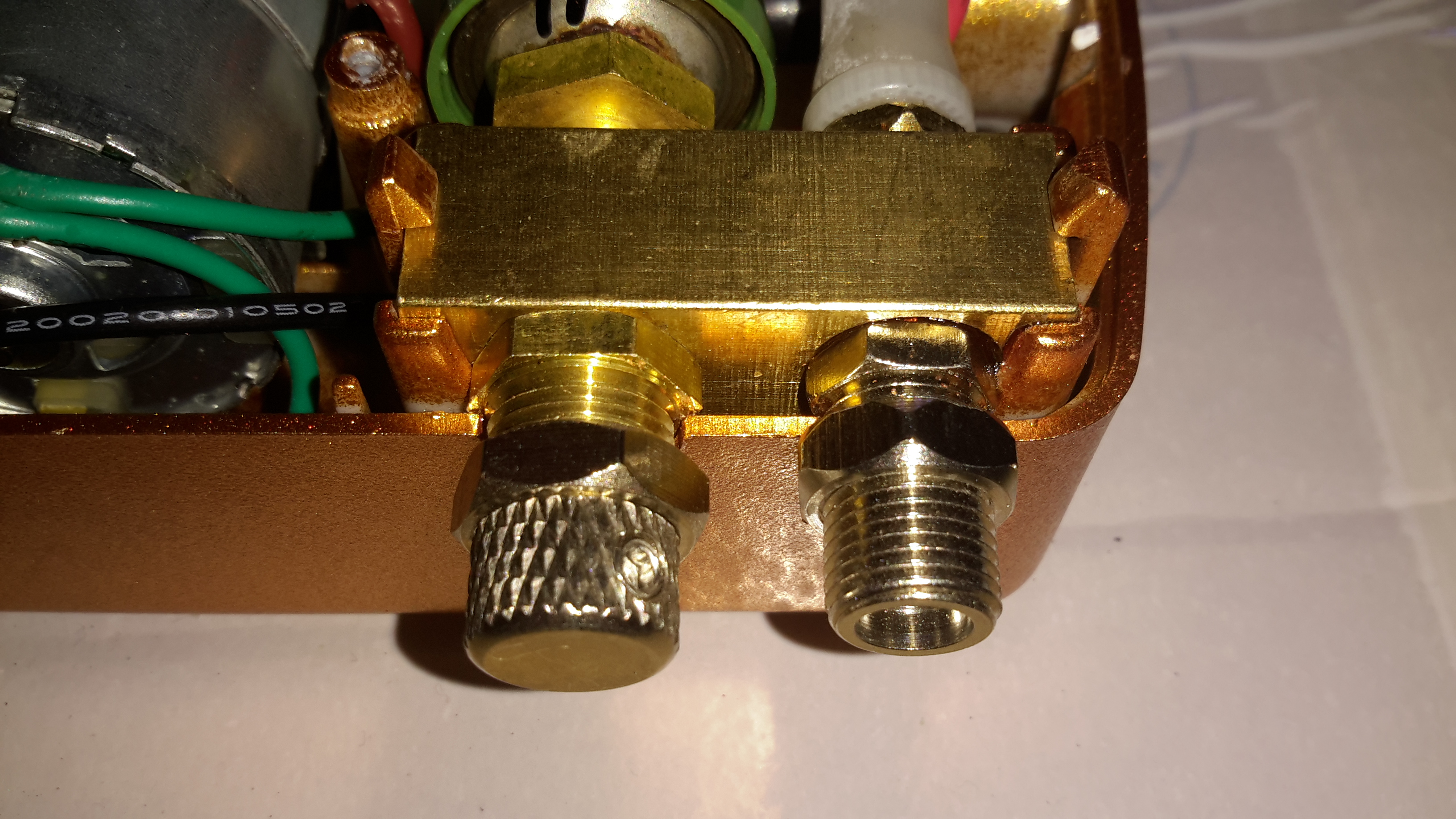
Air Block
Next to the air outlet fitting is an adjustment knob, supposedly for varying the pressure. However it’s just a piss-poorly designed adjustable relief valve that vents to atmosphere. There’s not much of a control range.
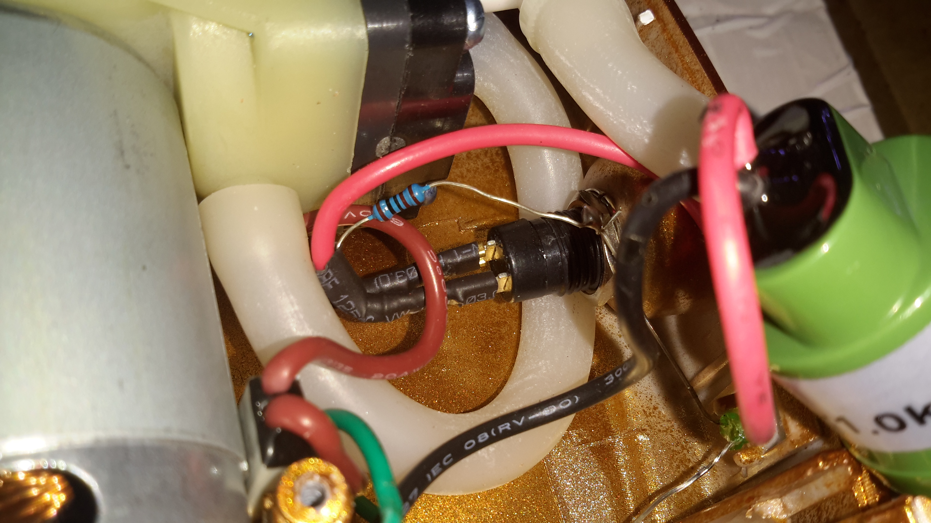
Messy Wiring
The wiring gets a bit messy where the power LED is concerned, with no heatshrink over the solder joints, but it’s adequate.
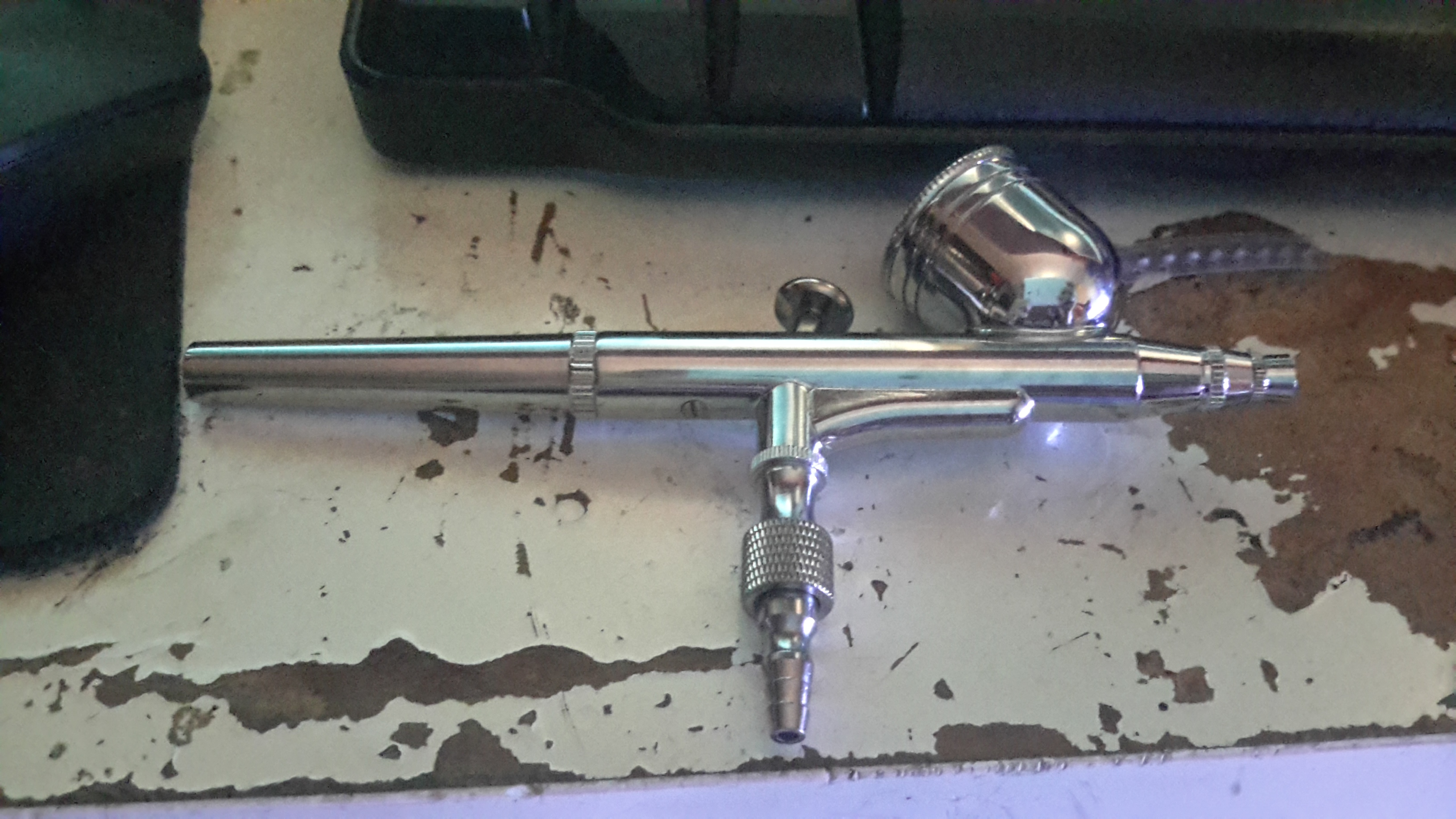
Airbrush
The airbrush itself isn’t too bad. It’s solid Brass, with a very nice Chrome finish. I’m not expecting miracles from a very cheap tool, but it certainly seems to be reasonable.
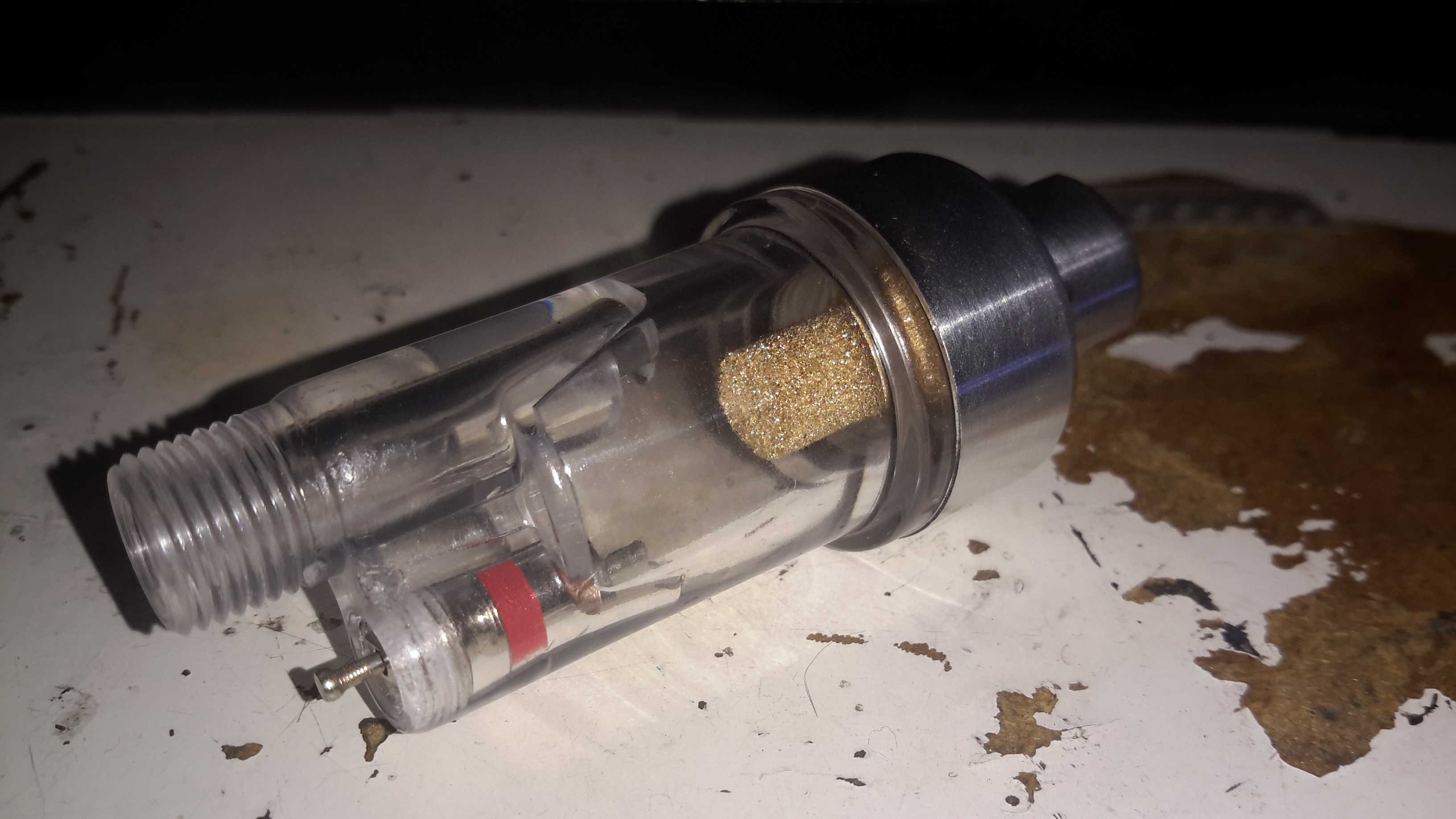
Water Trap
A moisture trap is supplied for the brush, to prevent water drops being sprayed out with the paint. Very handy.
As I’ve been posting some photos of decapped ICs lately, I thought I’d share the process I use personally for those that might want to give it a go 😉
The usual method for removing the epoxy package from the silicon is to use hot, concentrated Nitric Acid. Besides the obvious risks of having hot acids around, the decomposition products of the acid, namely NO² (Nitrogen Dioxide) & NO (Nitrogen Oxide), are toxic and corrosive. So until I can get the required fume hood together to make sure I’m not going to corrode the place away, I’ll leave this process to proper labs ;).
The method I use is heat based, using a Propane torch to destroy the epoxy package, without damaging the Silicon die too much.
TMS57002 Audio DSP
I start off, obviously, with a desoldered IC, the one above an old audio DSP from TI. I usually desolder en-masse for this with a heat gun, stripping the entire board in one go.
FLAMES!
Next is to apply the torch to the IC. A bit of practice is required here to get the heat level & time exactly right, overheating will cause the die to oxidize & blacken or residual epoxy to stick to the surface.
I usually apply the torch until the package just about stops emitting it’s own yellow flames, meaning the epoxy is almost completely burned away. I also keep the torch flame away from the centre of the IC, where the die is located.
Breathing the fumes from this process isn’t recommended, no doubt besides the obvious soot, the burning plastic will be emitting many compounds not brilliant for Human health!
Once the IC is roasted to taste, it’s quenched in cold water for a few seconds. Sometimes this causes such a high thermal shock that the leadframe cracks off the epoxy around the die perfectly.
All Your Die Belong To Us
Now that the epoxy has been destroyed, it breaks apart easily, and is picked away until I uncover the die itself. (It’s the silver bit in the middle of the left half). The heat from the torch usually destroys the Silver epoxy holding the die to the leadframe, and can be removed easily from the remaining package.
Decapped
BGA packages are usually the easiest to decap, flip-chip packages are a total pain due to the solder balls being on the front side of the die, I haven’t managed to get a good result here yet, I’ll probably need to chemically remove the first layer of the die to get at the interesting bits 😉
Slide
Once the die has been rinsed in clean water & inspected, it’s mounted on a glass microscope slide with a small spot of Cyanoacrylate glue to make handling easier.
Some dies require some cleaning after decapping, for this I use 99% Isopropanol & 99% Acetone, on the end of a cotton bud. Any residual epoxy flakes or oxide stuck to the die can be relatively easily removed with a fingernail – turns out fingernails are hard enough to remove the contamination, but not hard enough to damage the die features.
Once cleaning is complete, the slide is marked with the die identification, and the photographing can begin.
Microscope Mods
I had bought a cheap eBay USB microscope to get started, as I can’t currently afford a proper metallurgical microscope, but I found the resolution of 640×480 very poor. Some modification was required!
Modified Microscope
I’ve removed the original sensor board from the back of the optics assembly & attached a Raspberry Pi camera board. The ring that held the original sensor board has been cut down to a minimum, as the Pi camera PCB is slightly too big to fit inside.
The stock ring of LEDs is run direct from the 3.3v power rail on the camera, through a 4.7Ω resistor, for ~80mA. I also added a 1000µF capacitor across the 3.3v supply to compensate a bit for the long cable – when a frame is captured the power draw of the camera increases & causes a bit of voltage drop.
The stock lens was removed from the Pi camera module by careful use of a razor blade – being too rough here *WILL* damage the sensor die or the gold bond wires, which are very close to the edge of the lens housing, so be gentle!
Mounting Base
The existing mount for the microscope is pretty poor, so I’ve used a couple of surplus ceramic ring magnets as a better base, this also gives me the option of raising or lowering the base by adding or removing magnets.
To get more length between the Pi & the camera, I bought a 1-meter cable extension kit from Pi-Cables over at eBay, cables this long *definitely* require shielding in my space, which is a pretty aggressive RF environment, or interference appears on the display. Not surprising considering the high data rates the cable carries.
The FFC interface is hot-glued to the back of the microscope mount for stability, for handheld use the FFC is pretty flexible & doesn’t apply any force to the scope.
Die Photography
Since I modified the scope with a Raspberry Pi camera module, everything is done through the Pi itself, and the raspistill command.
Pi LCD
The command I’m currently using to capture the images is:
raspistill -ex auto -awb auto -mm matrix -br 62 -q 100 -vf -hf -f -t 0 -k -v -o CHIPNAME_%03d.jpg
This command waits between each frame for the ENTER key to be pressed, allowing me to position the scope between shots. Pi control & file transfer is done via SSH, while I use the 7″ touch LCD as a viewfinder.
The direct overhead illumination provided by the stock ring of LEDs isn’t ideal for some die shots, so I’m planning on fitting some off-centre LEDs to improve the resulting images.
Image Processing
Obviously I can’t get an ultra-high resolution image with a single shot, due to the focal length, so I have to take many shots (30-180 per die), and stitch them together into a single image.
For this I use Hugin, an open-source panorama photo stitching package.
Hugin
Here’s Hugin with the photos loaded in from the Raspberry Pi. To start with I use Hugin’s built in CPFind to process the images for control points. The trick with getting good control points is making sure the images have a high level of overlap, between 50-80%, this way the software doesn’t get confused & stick the images together incorrectly.
Optimiser
After the control points are generated, which for a large number of high resolution images can take some time, I run the optimiser with only Yaw & Pitch selected for all images.
Optimising
If all goes well, the resulting optimisation will get the distance between control points to less than 0.3 pixels.
Panorama Preview
After the control points & optimisation is done, the resulting image can be previewed before generation.
Texas Instruments TMS67002
After all the image processing, the resulting die image should look something like the above, with no noticeable gaps.
Here’s some teardown photos of an old De La Rue coin counter, used in businesses for rapid counting of change into large bags.
Mechanism
An overview of the whole mechanical system of the counter. Coins are loaded into the drum at the rear of the machine, which sorts them into a row for the rubber belt to pick up & run through the counter. The coin type to be sorted is selected by turning the control knobs on the right.
The control knobs adjust the width & height of the coin channel so only the correct sized coins will be counted.
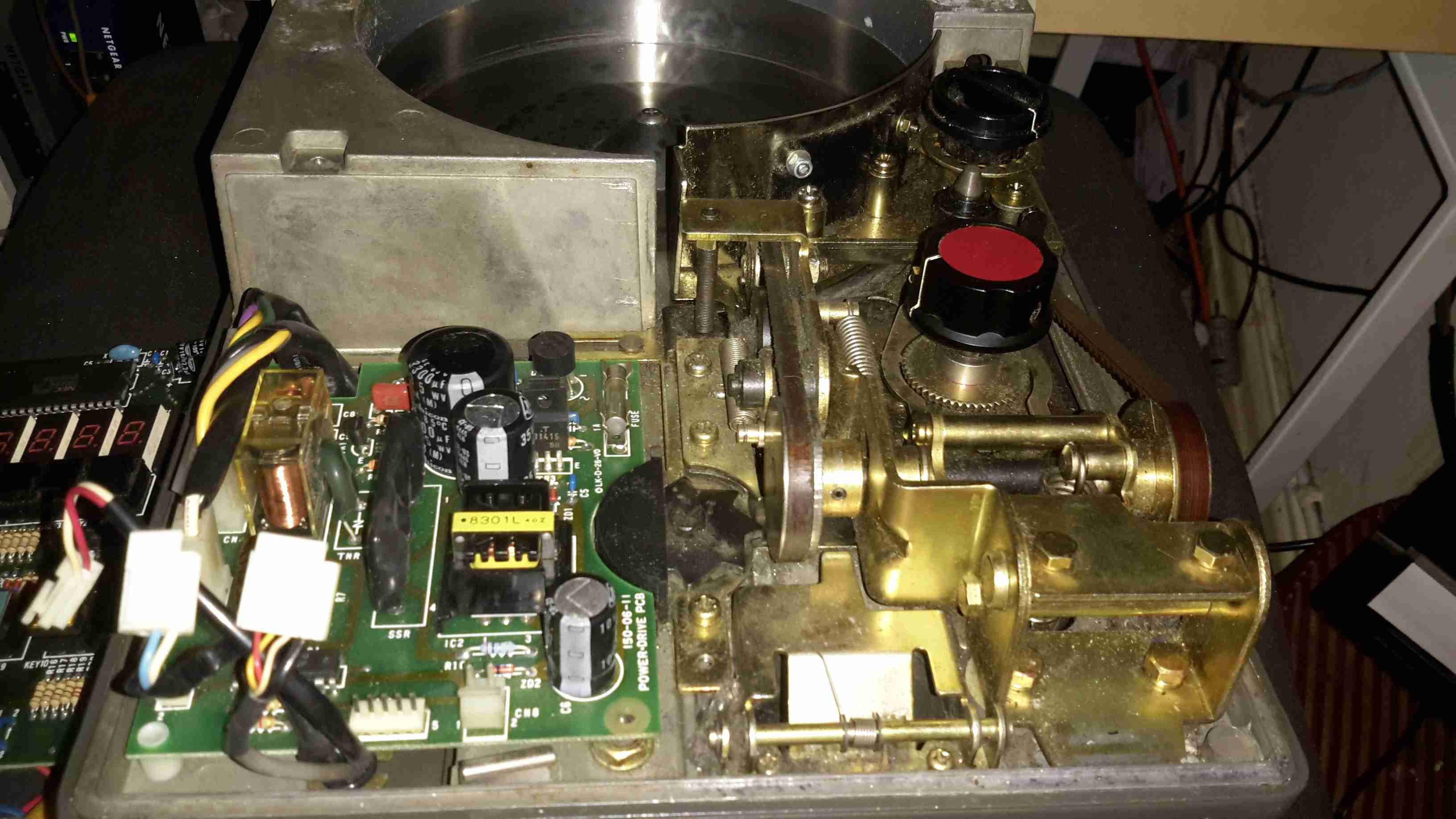
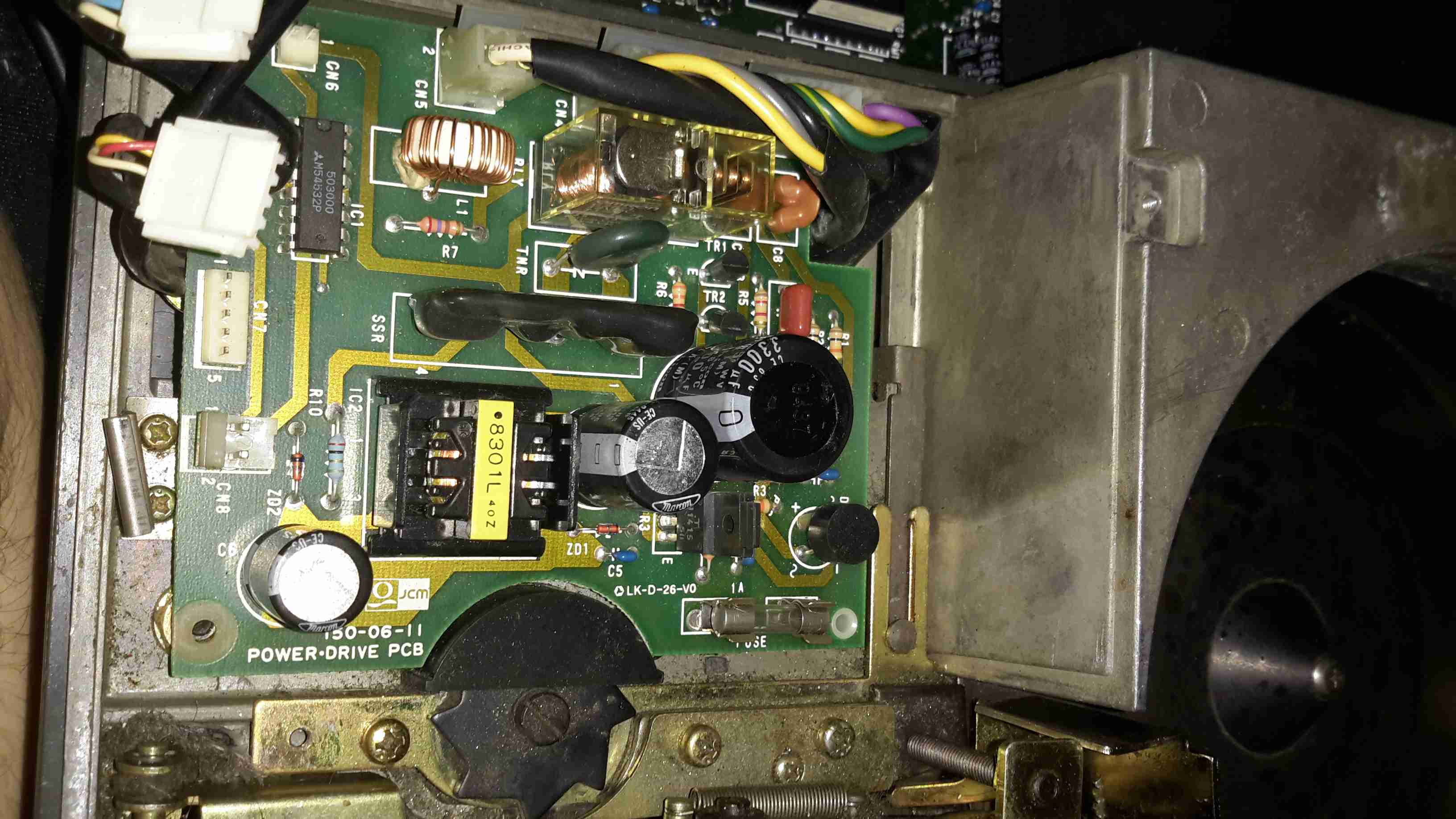
PSU & Switching
The counter is driven by a basic AC induction motor, the motor power relay & reversing relay is on this PCB, along with the 5v switching supply for the main CPU board.
The SMPS on this board looks like a standard mains unit, but it’s got one big difference. Under the frame next to the main motor is a relatively large transformer, with a 35v output. This AC is fed into the SMPS section of the PSU board to be converted to 5v DC for the logic.
I’m not sure why it’s been done this way, and have never seen anything similar before.
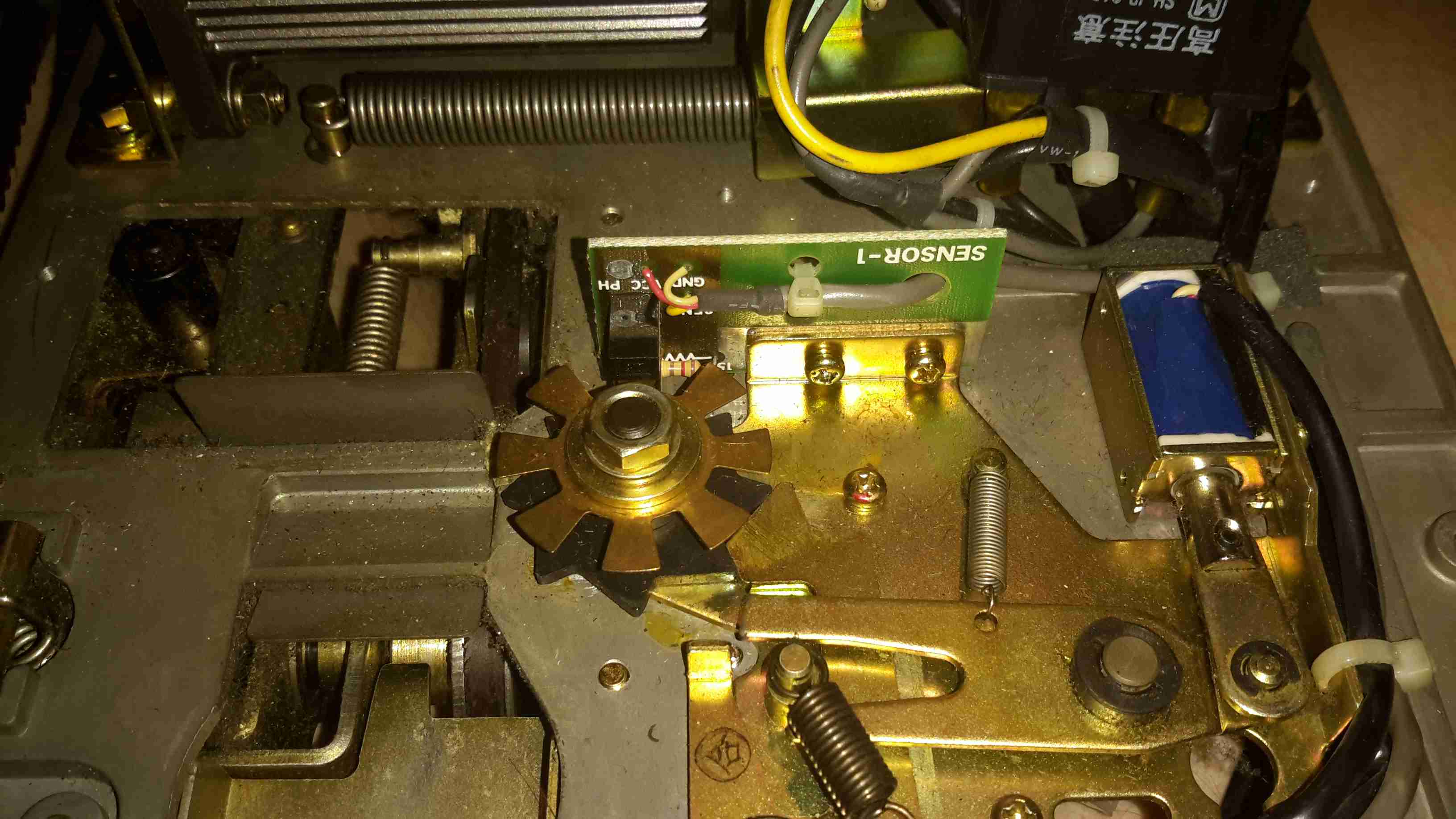
The edge of the coin channel can be seen here, the black star wheel rotates when a coin passes & registers the count.
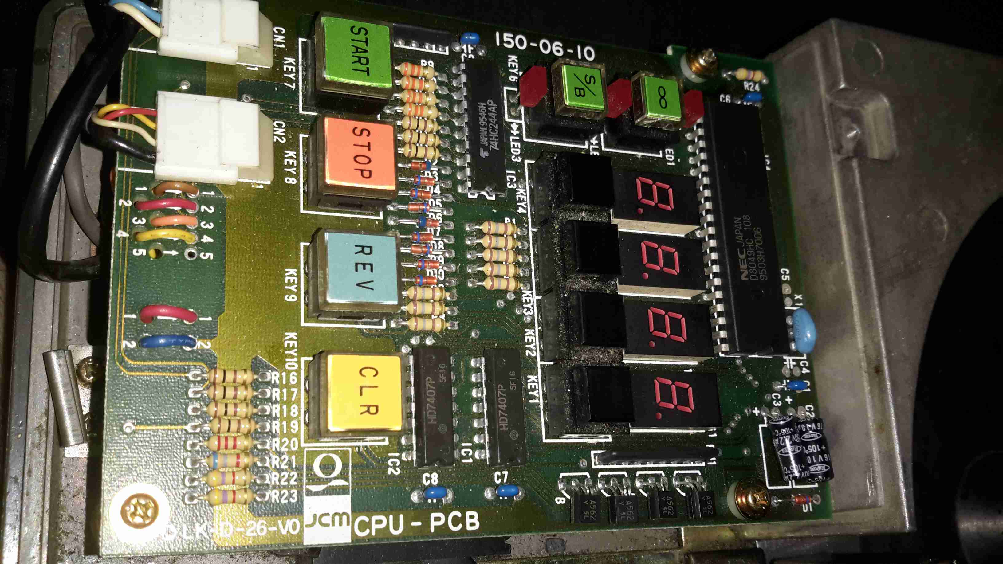
Controller PCB
Here’s the main controller PCB, IC date codes put the unit to about 1995. The main CPU is a NEC UPD8049HC 8-bit micro, no flash or EEPROM on this old CPU, simply mask ROM. Coin readout is done on the 4 7-segment LED displays. Not much to this counter, it’s both electronically & mechanically simple.
Counter Sensor
Coin counting is done by the star wheel mentioned above, which drives the interrupter disc on this photo-gate. The solenoid locks the counter shaft to prevent over or under counting when a set number of coins is to be counted.
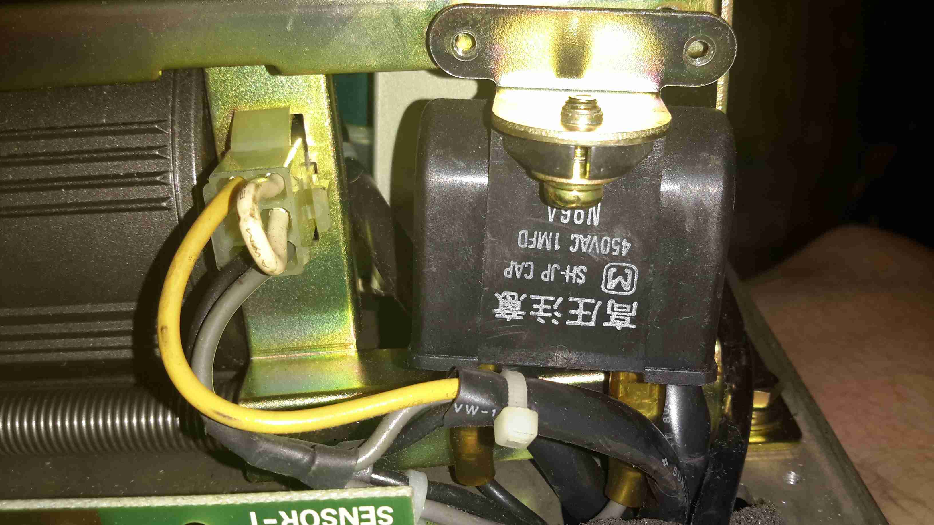
Motor Run Capacitor
Under the frame, here on the left is the small induction motor, only 6W, 4-pole. The run cap for the motor is in the centre, and the 35v transformer is just visible behind it.
Main Motor Drive
Main drive to the coin sorting mech is through rubber belts, and bevel gears drive the coin drum.
For as long as I can remember I’ve been using Trangia-type alcohol fuelled stoves when I go camping, even though these have served my needs well they’re very limited & tend to waste fuel. I did some looking around for Paraffin/Kerosene fuelled stoves instead, as I already have this fuel on site.
I found very good reviews on the Optimus Nova above, so I decided to go for this one.
This stove can run on many different fuel types, “white gas” (petrol without any vehicle additives) Diesel, Kerosene & Jet A.
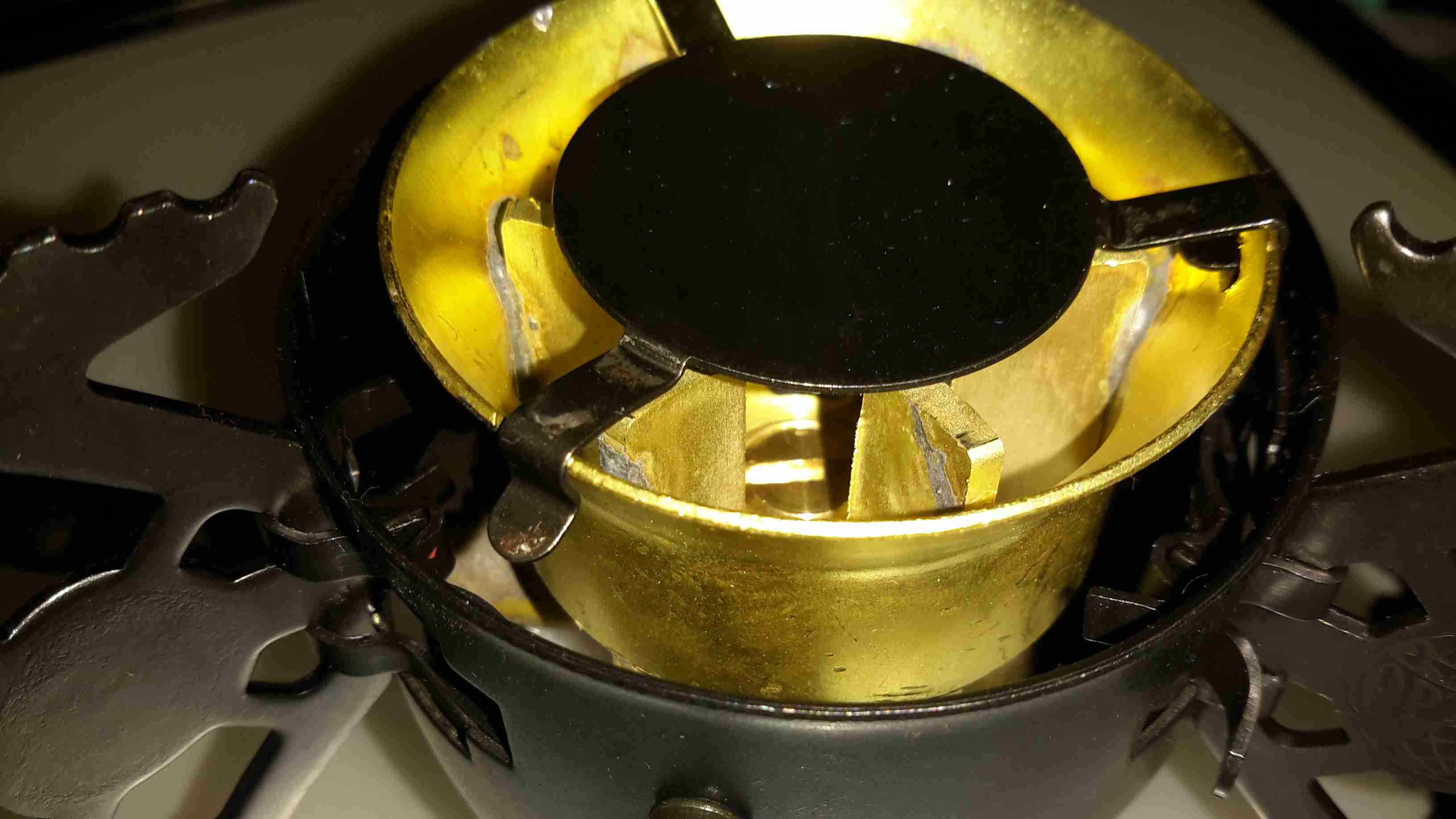
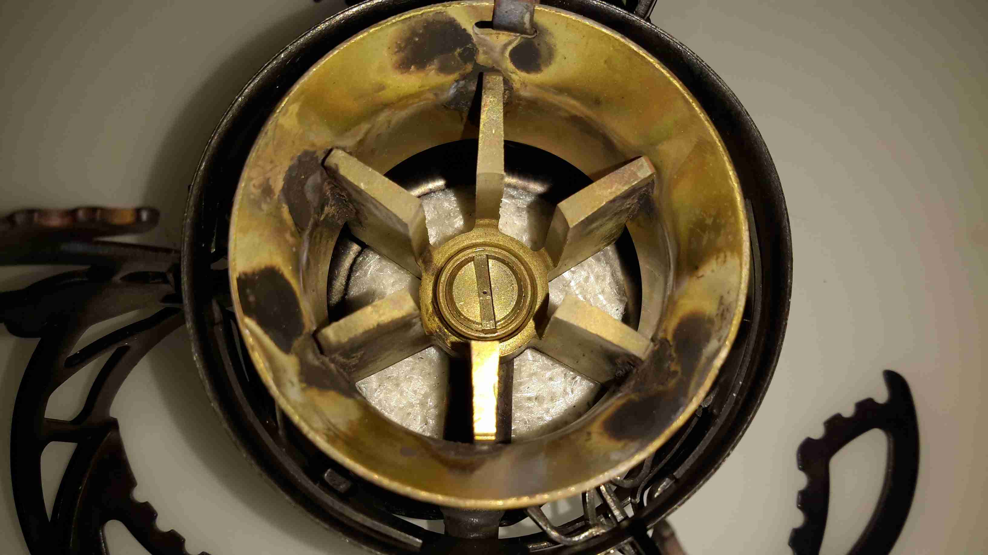
Burner
Here’s the “hot end” of the device, the burner itself. This is made in two cast Brass sections, that are brazed together. The fuel jet can be just seen in the centre of the casting.
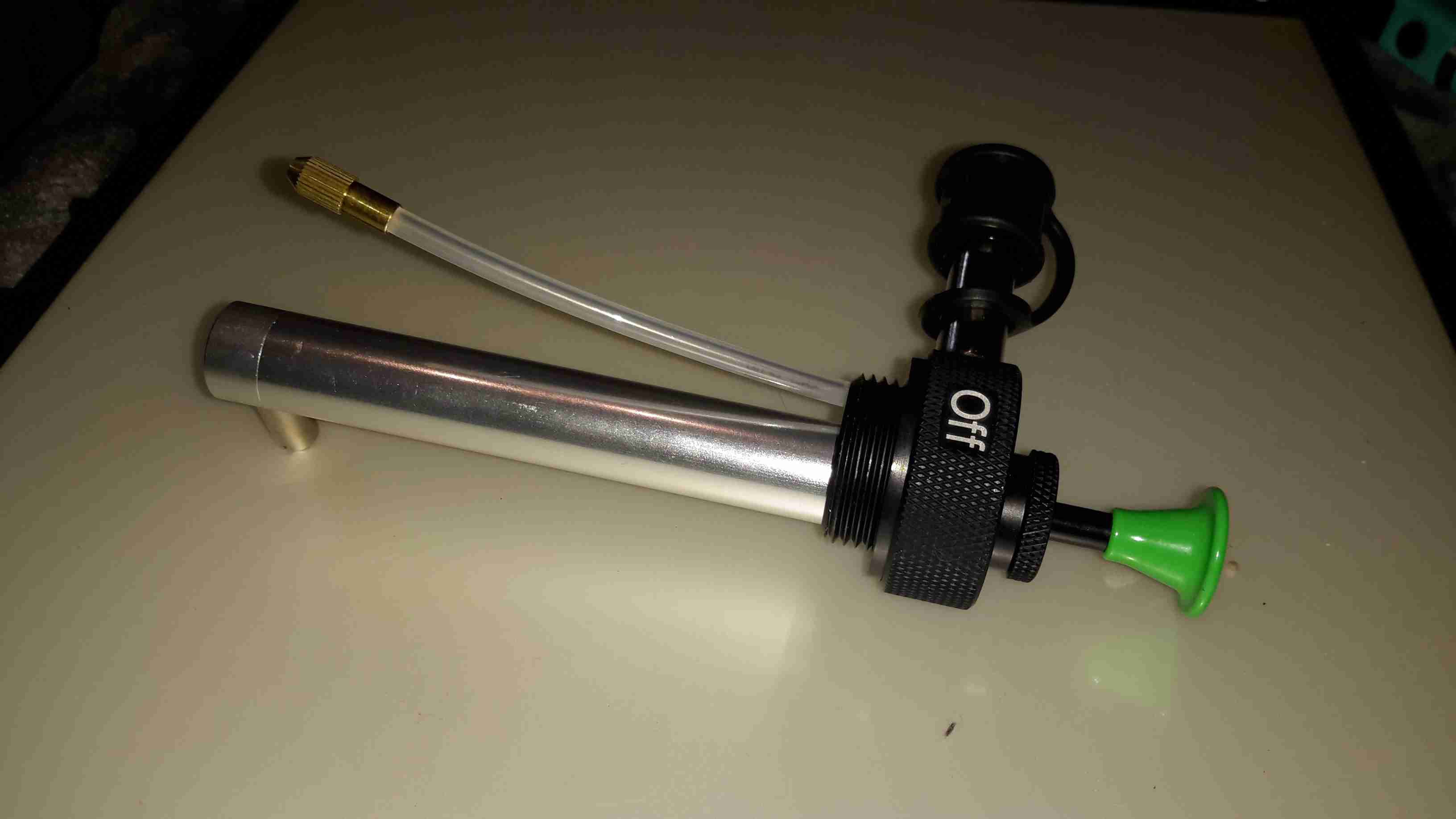
Fuel Pump
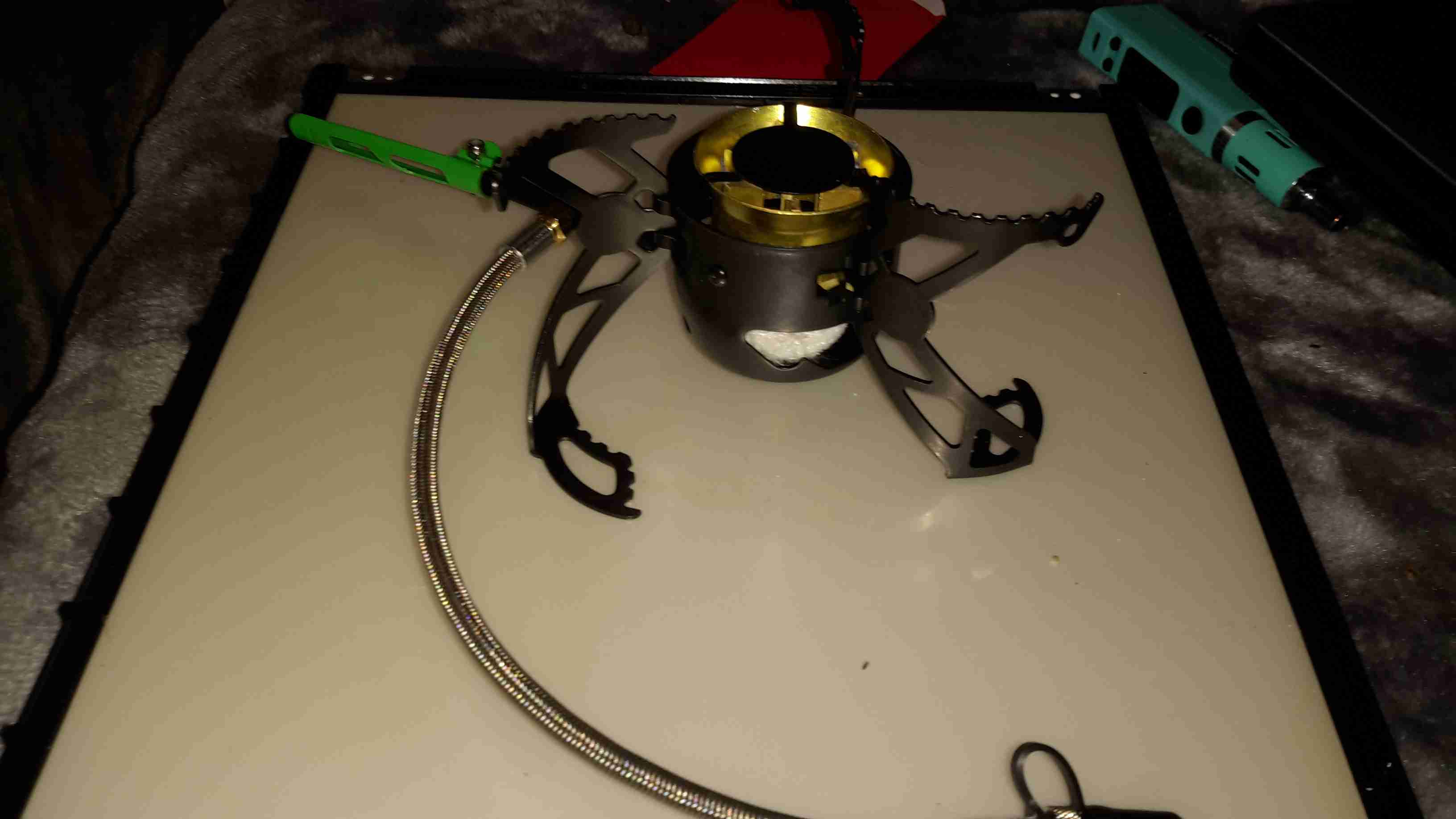
The fuel bottle is pressurised with a pump very similar to the ones used on Paraffin pressure lamps, so I’m used to this kind of setup. The fuel dip tube has a filter on the end to stop any munge gumming up the valves or the burner jet.
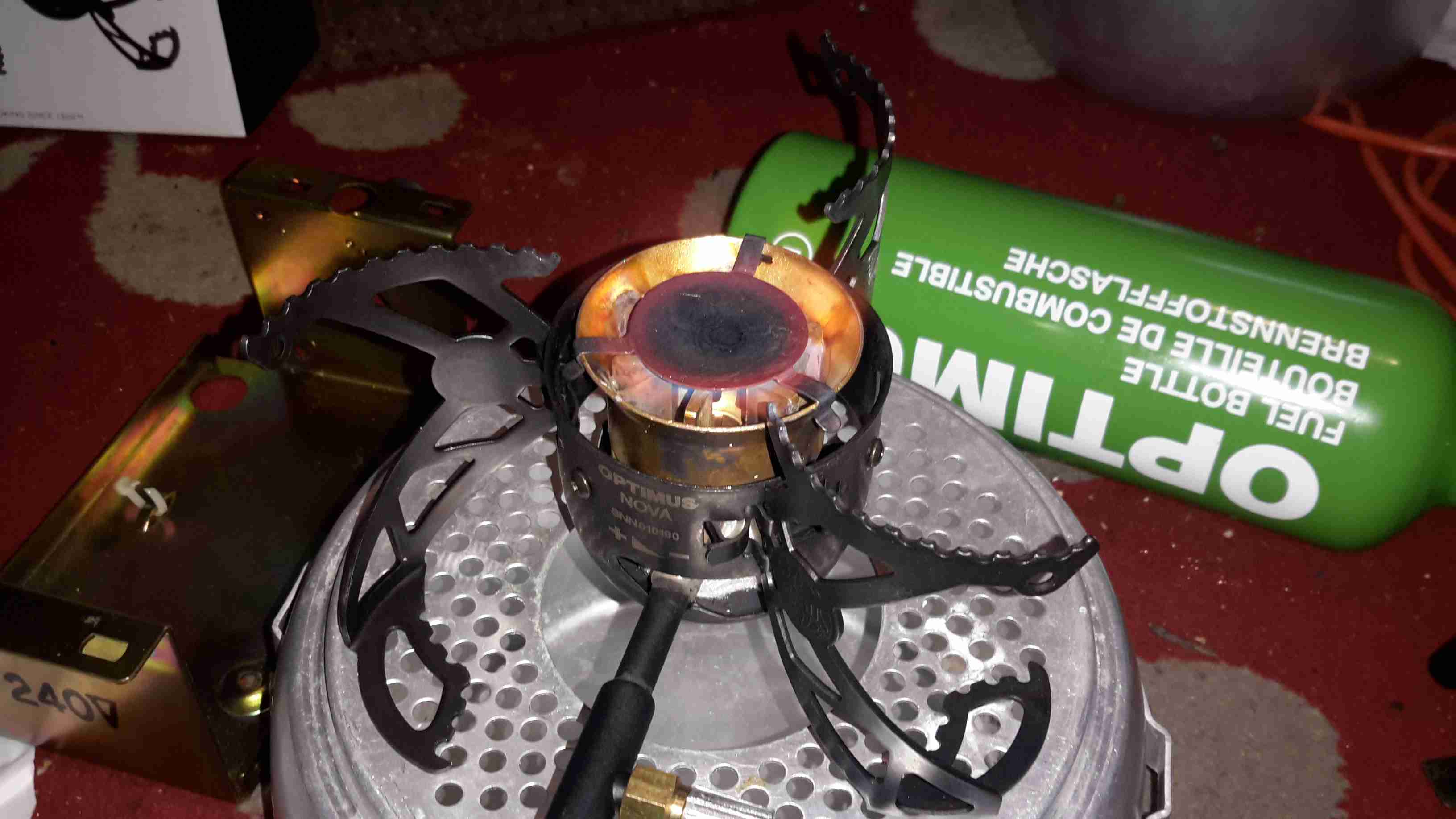
Pre-Heating
As with all liquid-fuelled vapour burners, it has to be preheated. There’s a fibreglass pad in the bottom of the burner for this, and can be soaked with any fuel of choice. The manual states to preheat with the fuel in the bottle, but as I’m using Paraffin, this would be very smoky indeed, so here it’s being preheated with a bit of Isopropanol.
The fuel bottle can be seen in the background as well, connected to the burner with a flexible hose. The main burner control valve is attached to the green handle bottom centre.
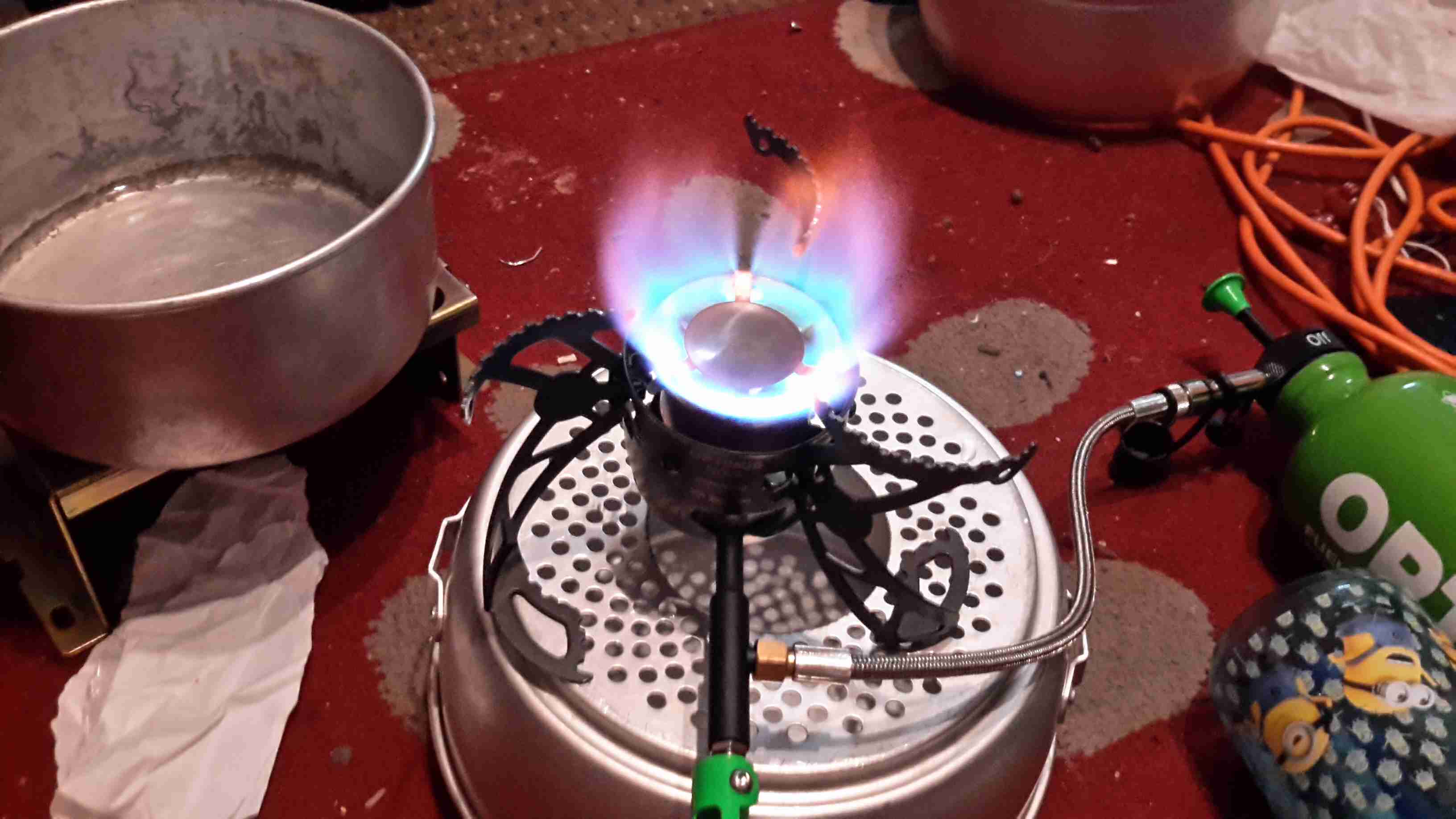
Simmer
Once the preheating flame has burned down, the fuel valve can be opened, here’s the stove burning Paraffin on very low simmer. (An advantage over the older alcohol burners I’m used to – adjustable heat!)
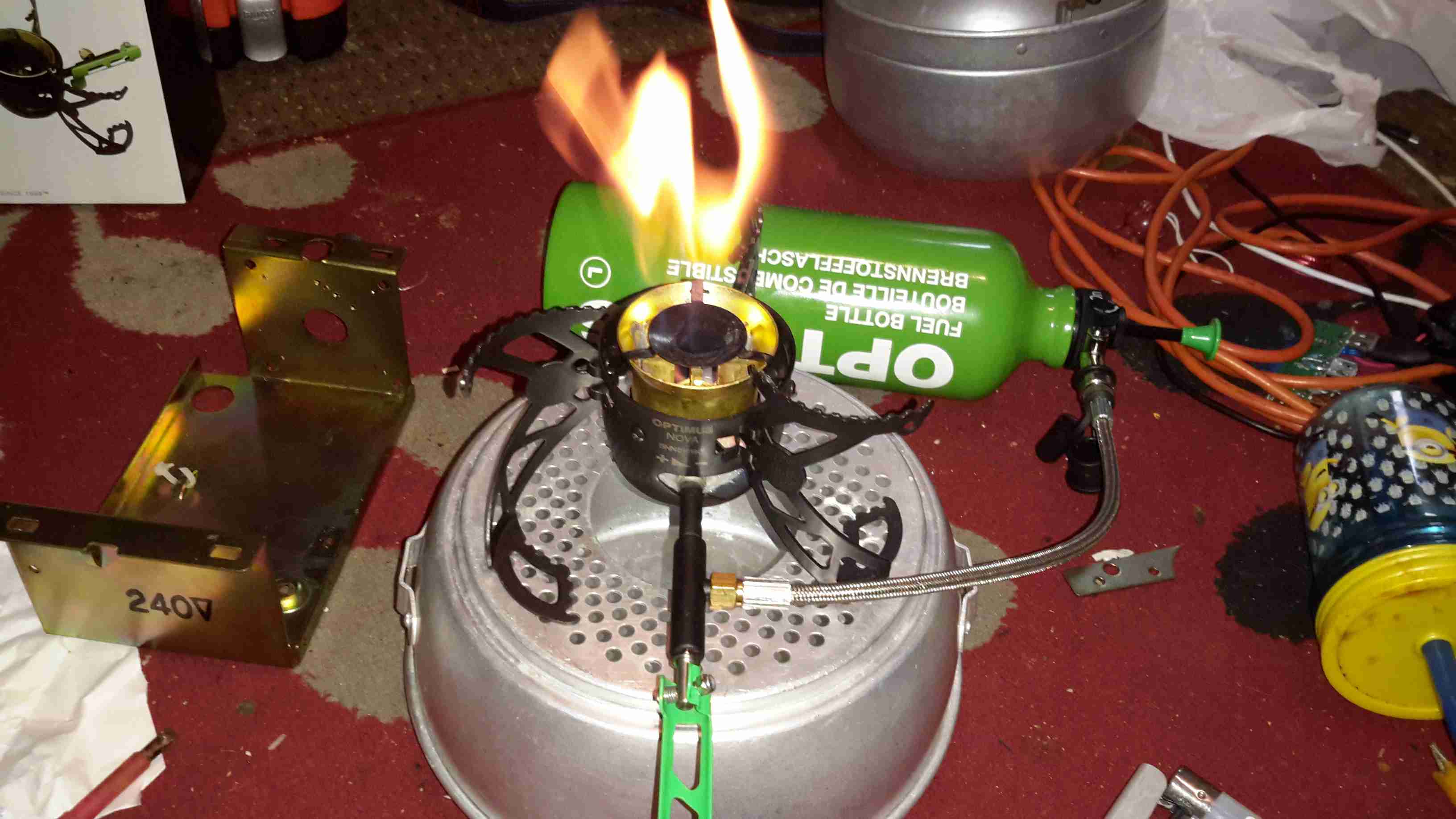
Full Power!
Opening the control valve a couple of turns gives flamethrower mode. At full power, the burner is a little loud, but no louder than my usual Paraffin pressure lamps.
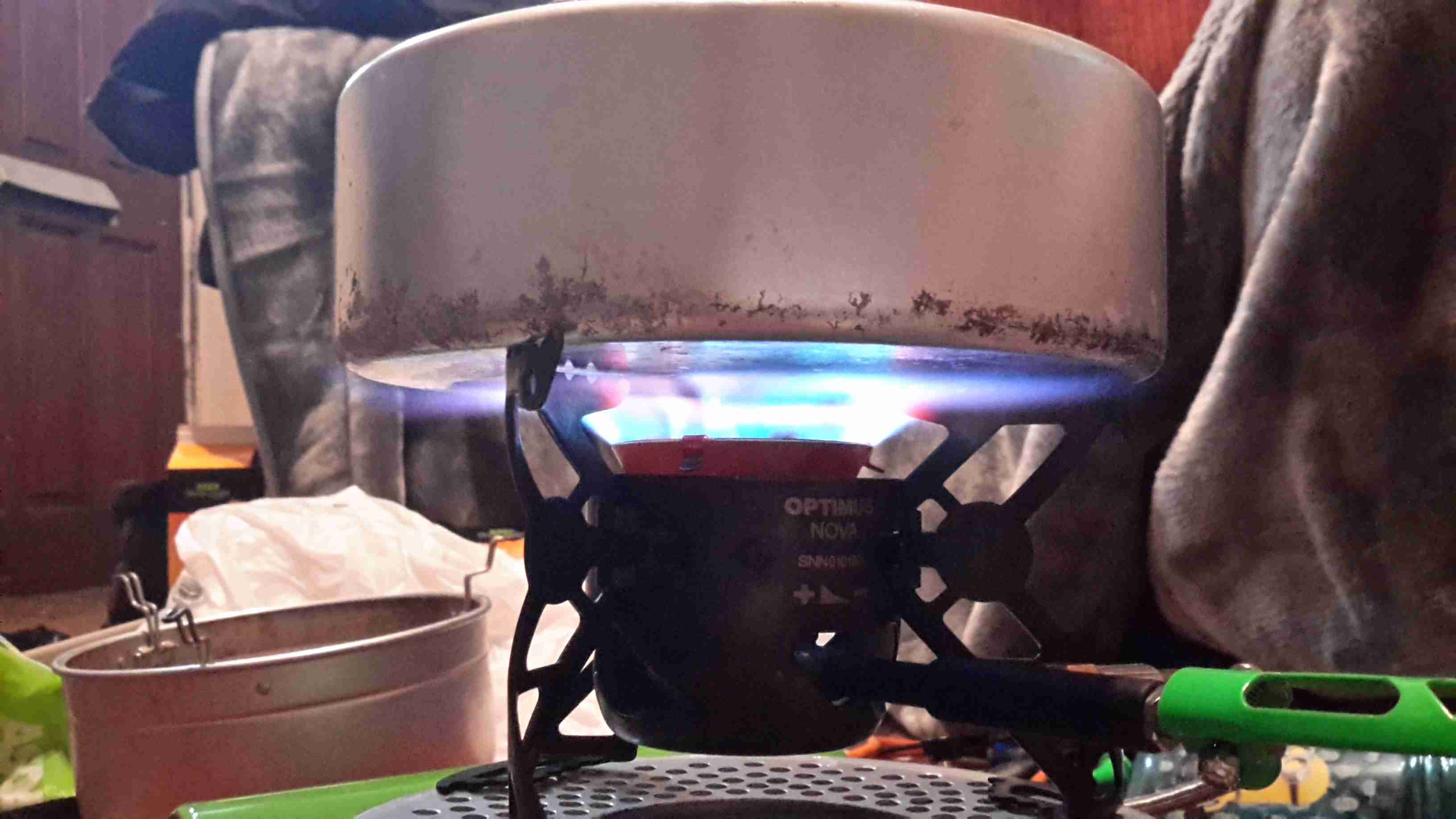
Flame Pattern
With a pan of water on the stove, the flame covers the entire base of the pan. Good for heat transfer. This stove was able to boil 1L of water from cold in 5 minutes. A little longer than the manual states, but that’s still much quicker than I’m used to!
Fuel Jet
The top of the burner opens for cleaning, here’s a look at the jet in the centre of the burner. The preheating pad can be seen below the brass casting.
In the past, I’ve used RC type LiPo packs for my mobile power requirements, but these tend to be a bit bulky, since they’re designed for very high discharge current capability – powering large motors in models is a heavy job.
I recently came across some Samsung Galaxy Tab 10.1 battery packs on eBay very cheaply, at £2.95 a piece. For this price I get 6800mAh of capacity at 4.2v, for my 12v requirements, 3 packs must be connected in series, for a total output of 12.6v fully charged.
For an initial pack, I got 9 of these units, to be connected in 3 sets of 3 to make 20Ah total capacity.There are no control electronics built into these batteries – it’s simply a pair of 3400mAh cells connected in parallel through internal polyfuses, and an ID EEPROM for the Tab to identify the battery.
This means I can just bring the cell connections together with the original PCB, without having to mess with the welded cell tabs.
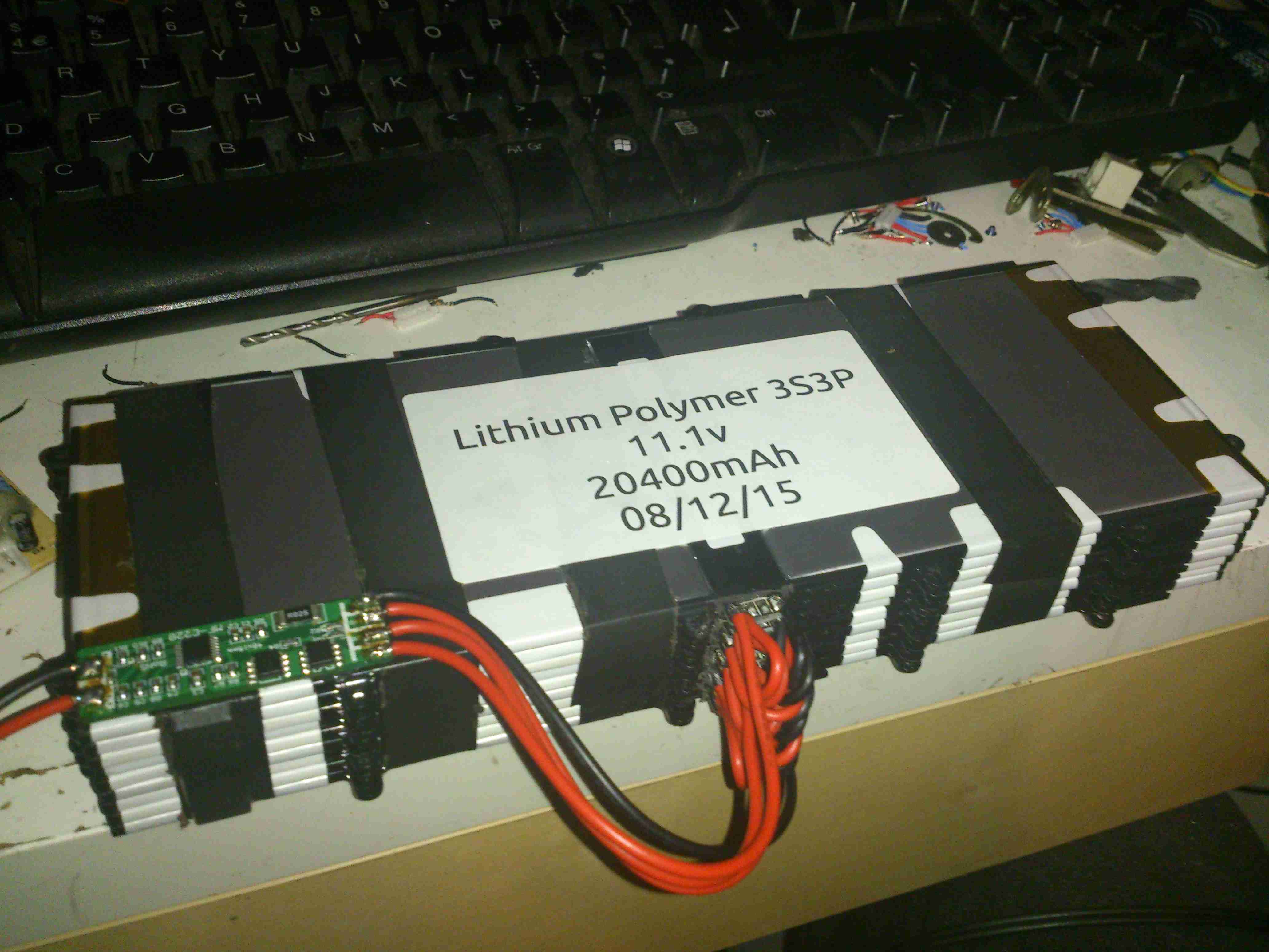
Battery Pack
Here’s the pack with it’s cell connections finished & a lithium BCM connected. This chemistry requires close control of voltages to remain stable, and with a pack this large, a thermal runaway would be catastrophic.
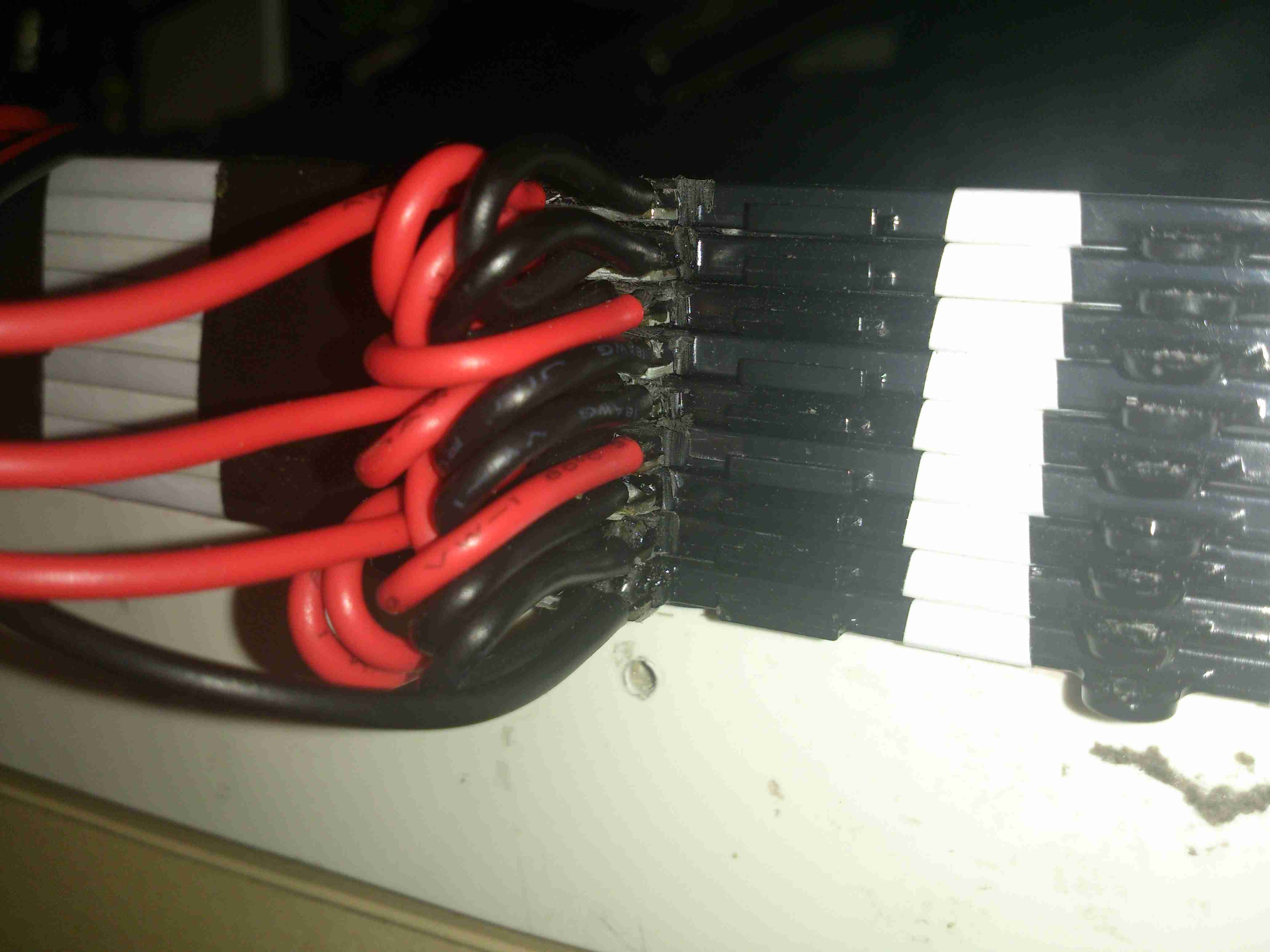
Cell Links
The OEM battery connector has been removed, and my series-parallel cell connections are soldered on, with extra lead-outs for balancing the pack. This was the most time-consuming part of the build.
If all goes well with the life of this pack for utility use, I’ll be building another 5 of these, for a total capacity of 120Ah. This will be extremely useful for portable use, as the weight is about half that of an equivalent lead-acid.
The multimode dimming/flashing modes on Chinese torches have irritated me for a while. If I buy a torch, it’s to illuminate something I’m doing, not to test if people around me have photosensitive epilepsy.
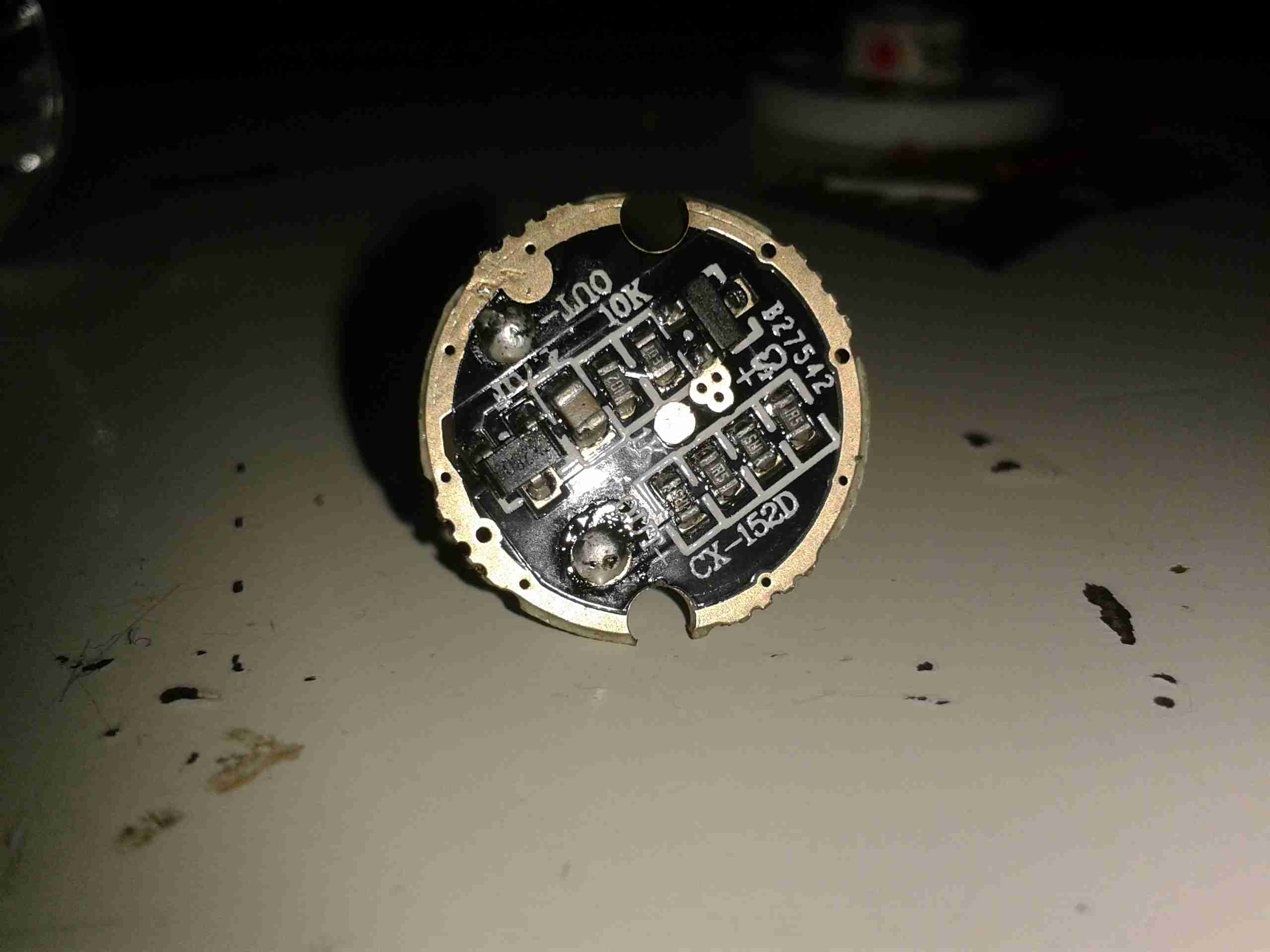
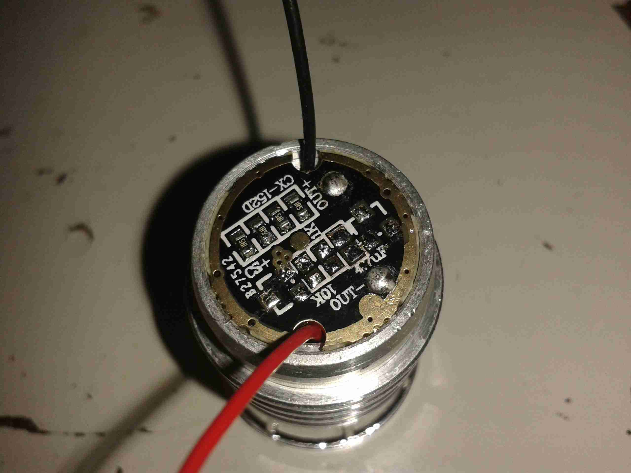
Looking at the PCB in the LED module of the torch, a couple of components are evident:
LED Driver PCB
There’s not much to this driver, it’s simply resistive for LED protection (the 4 resistors in a row at the bottom of the board).
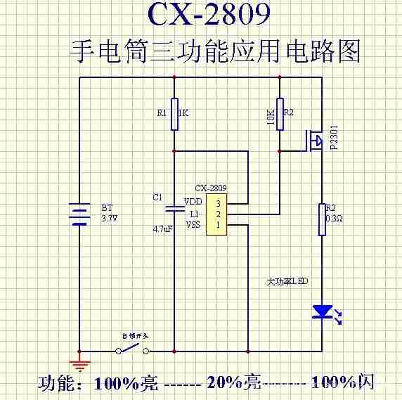
The components at the top are the multimode circuitry. The SOT-23 IC on the left is a CX2809 LED Driver, with several modes. The SOT-23 on the right is a MOSFET, for switching the actual LED itself. I couldn’t find a datasheet for the IC itself, but I did find a schematic that seems to match up with what’s on the board.
Schematic
Here’s that schematic, the only thing that needs to be done to convert the torch to single mode ON/OFF at full brightness, is to bridge out that FET.
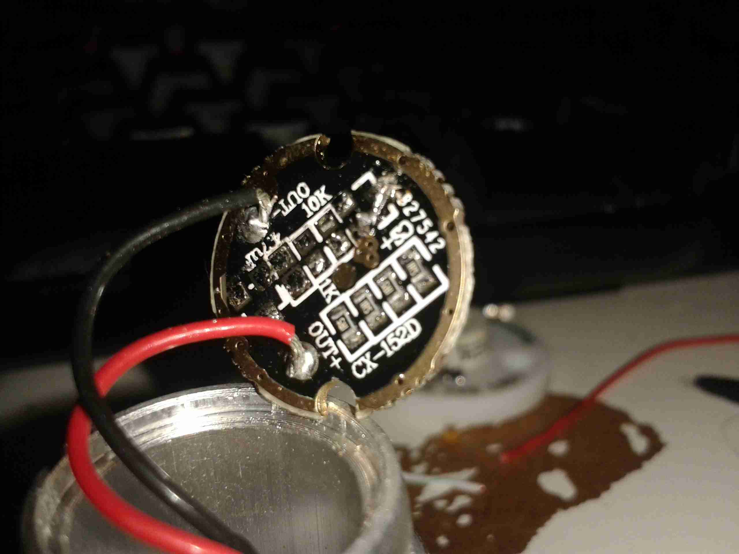
Components Desoldered
To help save the extra few mA the IC & associated circuitry will draw from the battery, I have removed all of the components involved in the multimode control. This leaves just the current limiting resistors for the LED itself.
Jumper Link
The final part above, is to install a small link across the Drain & Source pads of the FET. Now the switch controls the LED directly with no silly electronics in between. A proper torch at last.
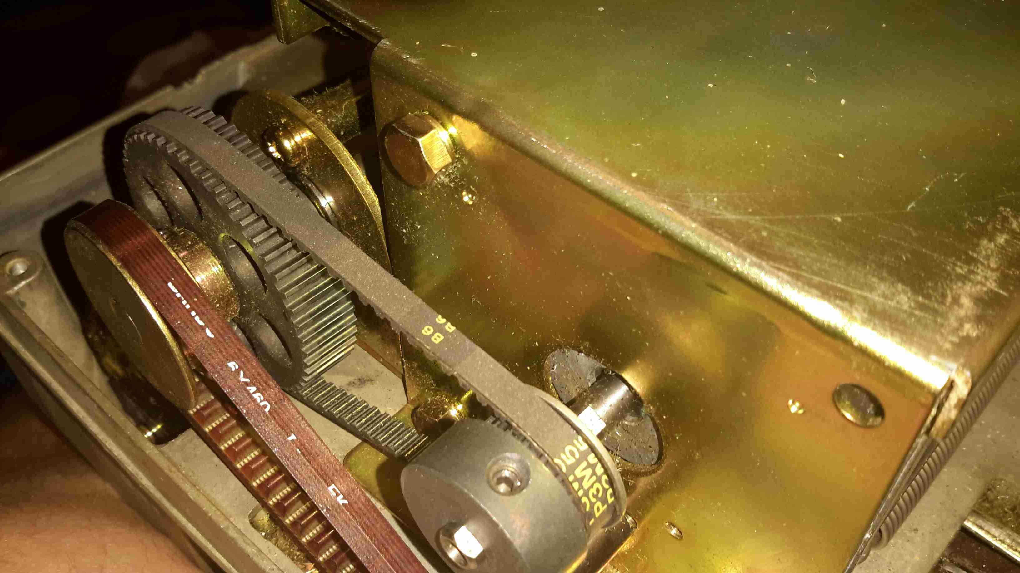
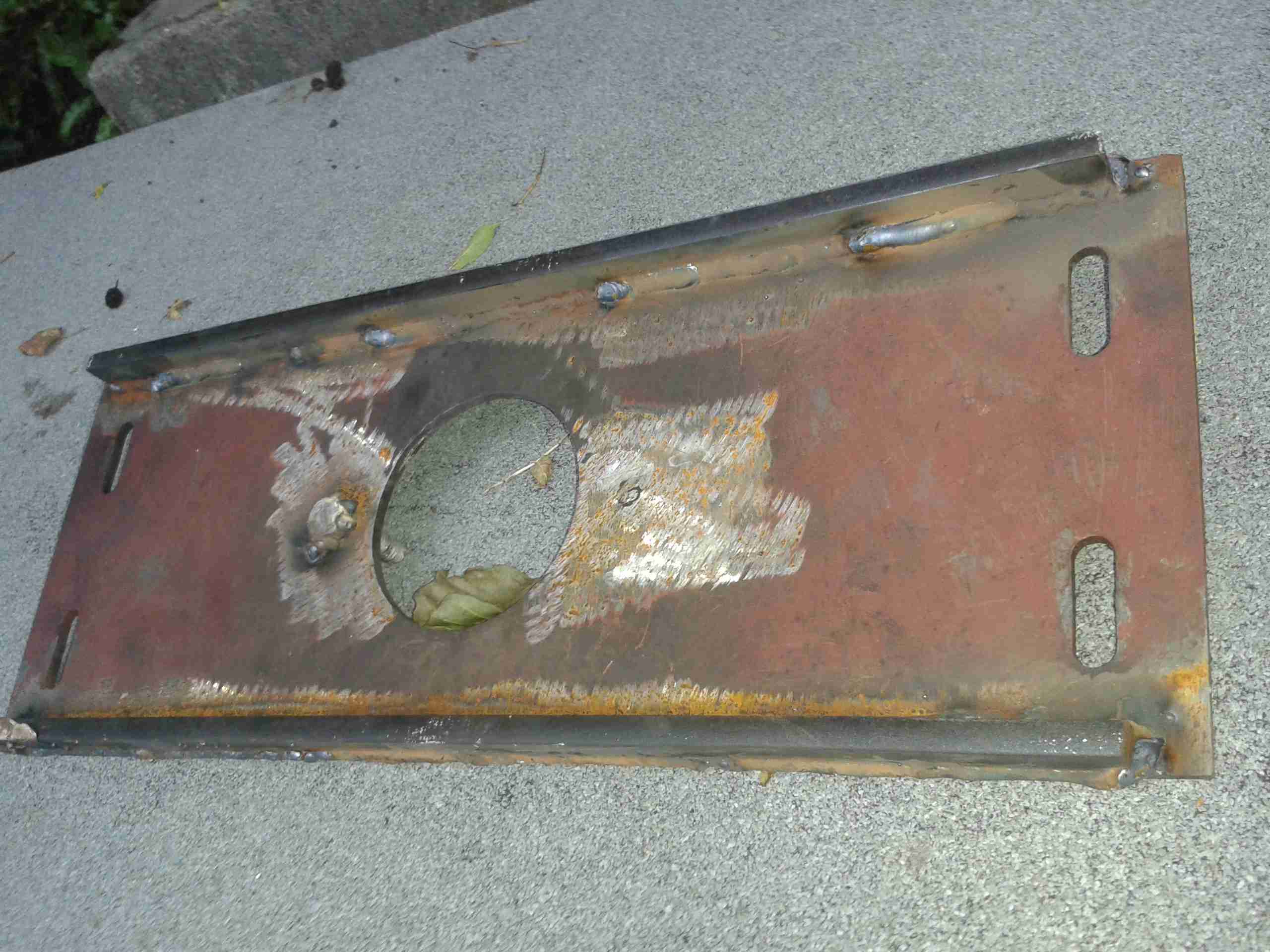
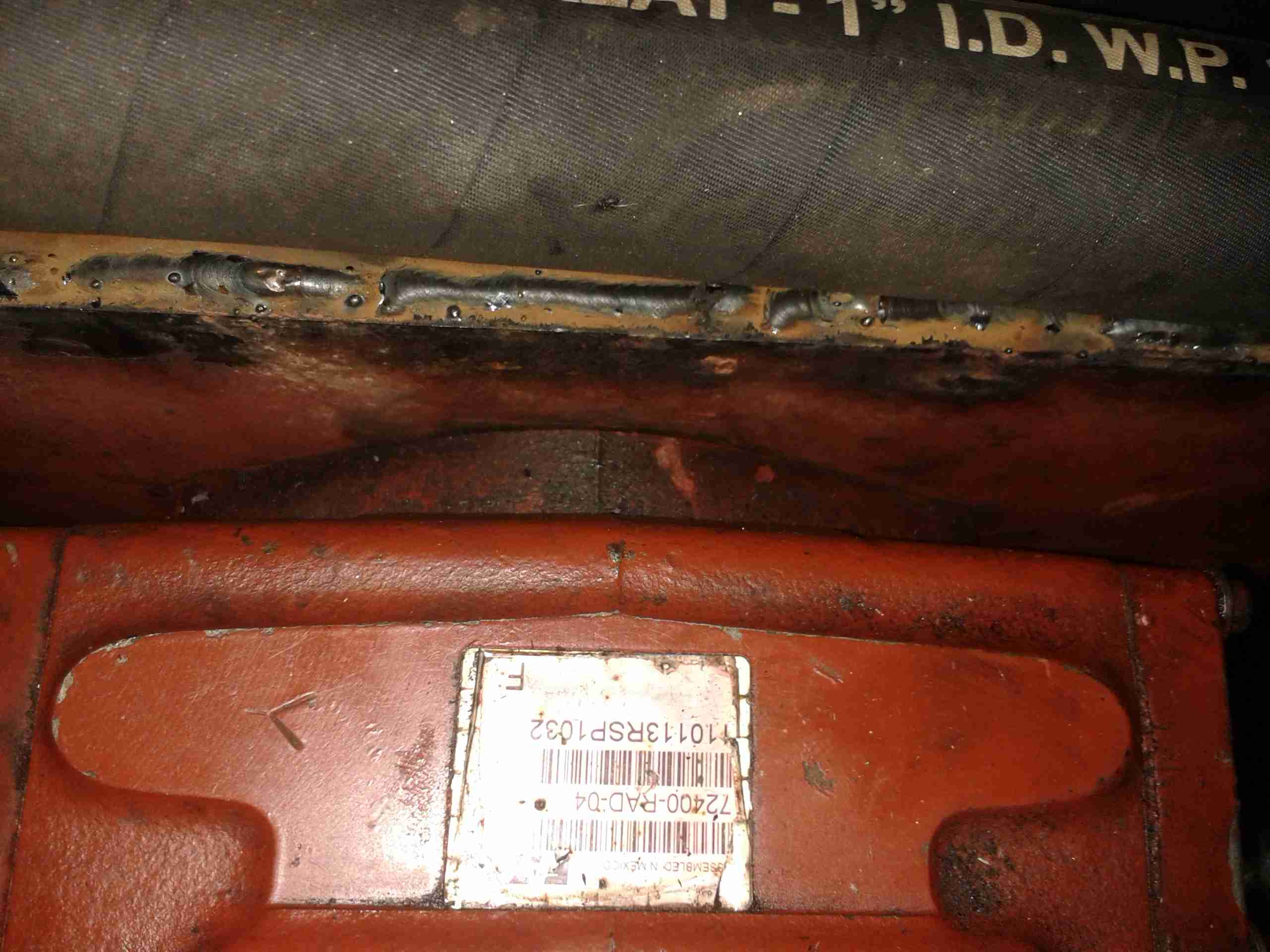
It’s time for the final part of getting the boat’s engine & drive back together, now I have the new coupling hub. I decided to address one of the issues with the pump mounting while I had everything in bits. When the hydraulic drive was installed, a custom plate was laser cut to fit the pump stack to, as we had no bellhousing with a standard mounting pattern.
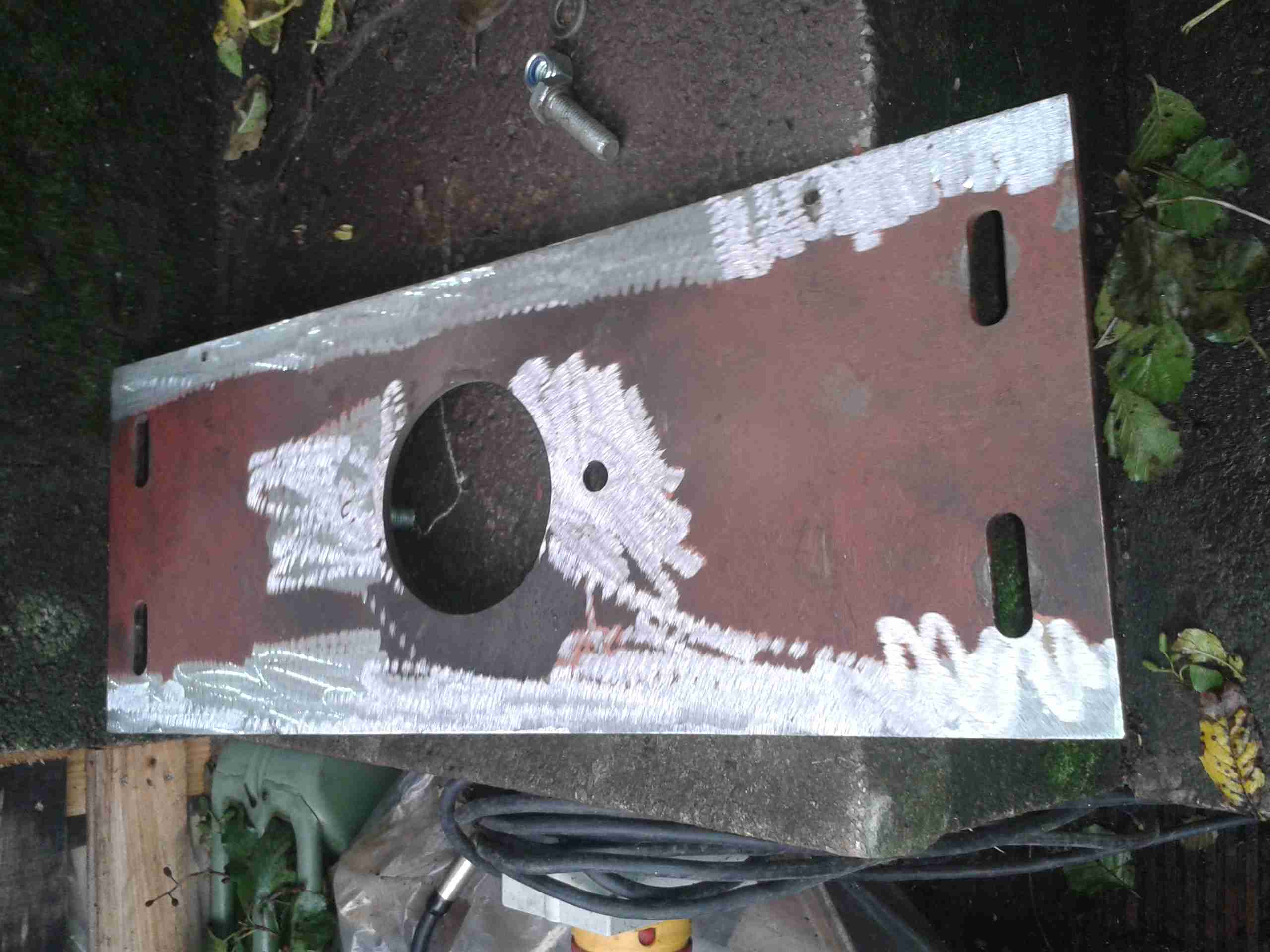
Even though this plate is 10mm steel, under full load it actually bends – so to strengthen it along the long edge, I have welded a pair of ribs to the plate.
Pump Mounting Plate
The mounting plate as removed from the mounting brackets. The slotted holes at the sides allow for some movement to adjust the position of the pump & flywheel coupling.
Prepared For Welding
I ground off the paint & grease with an abrasive disc, and am replacing one of the pump mounting studs while I’m at it.
Strengthening Ribs
Here’s the plate after welding. a pair of 10mm bars have been attached along the edges, this will give the mounting significantly more strength on the long axis & prevent any deformation.
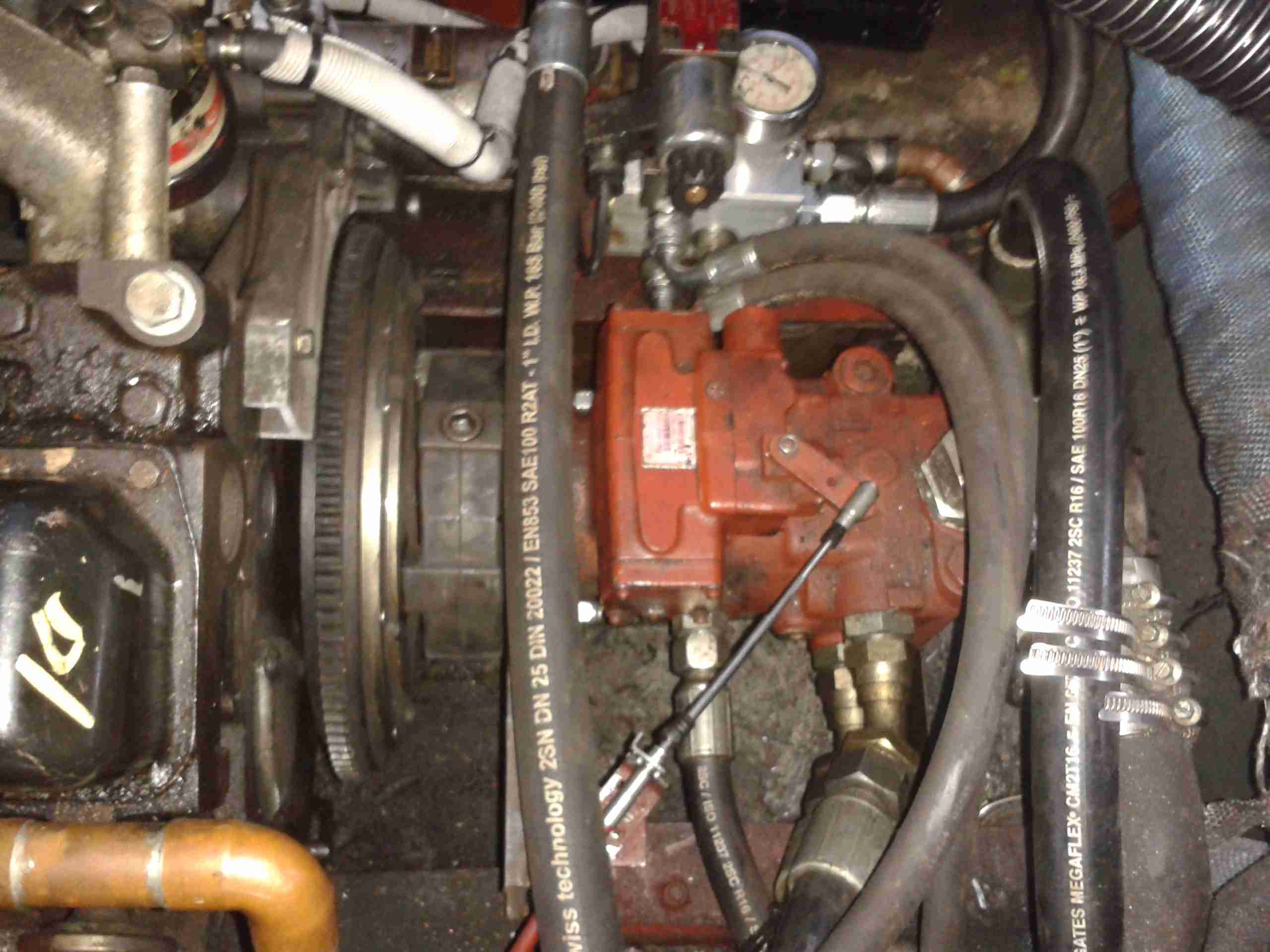
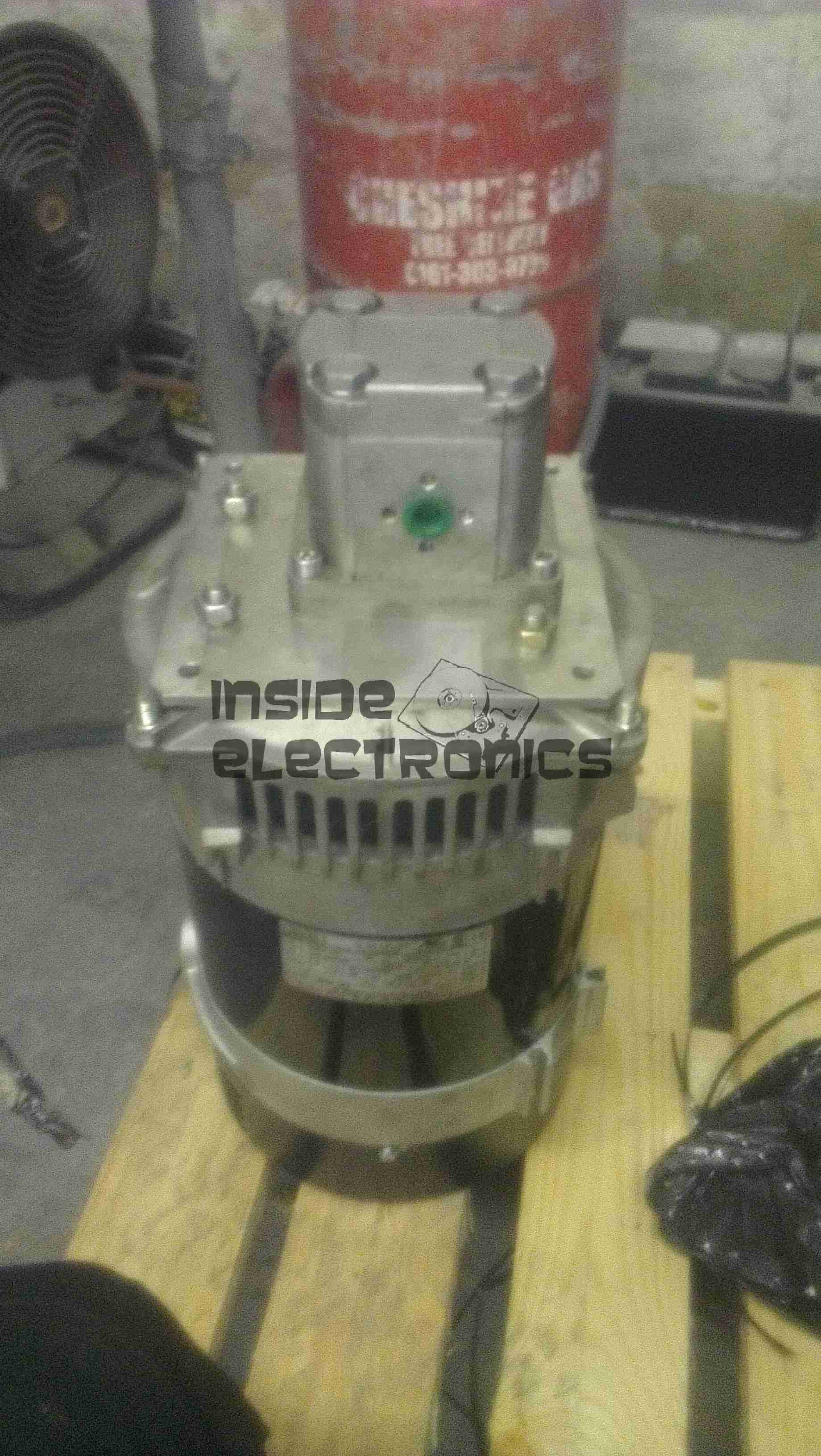
Pump On Hoist
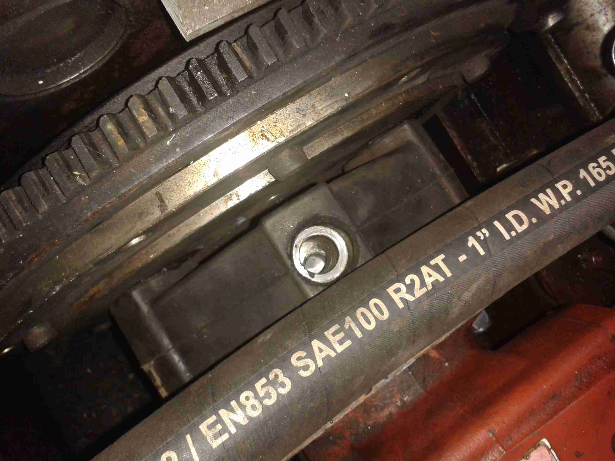
Here the plate has been loosely mounted on it’s brackets, & I’ve got the pump stack with it’s associated tangle of hoses on the chain hoist. This unit is very heavy on it’s own – a 2 man job to lift it into place on it’s mounts – with the very stiff hydraulic hoses attached & filled with oil it’s absolutely unmanageable.
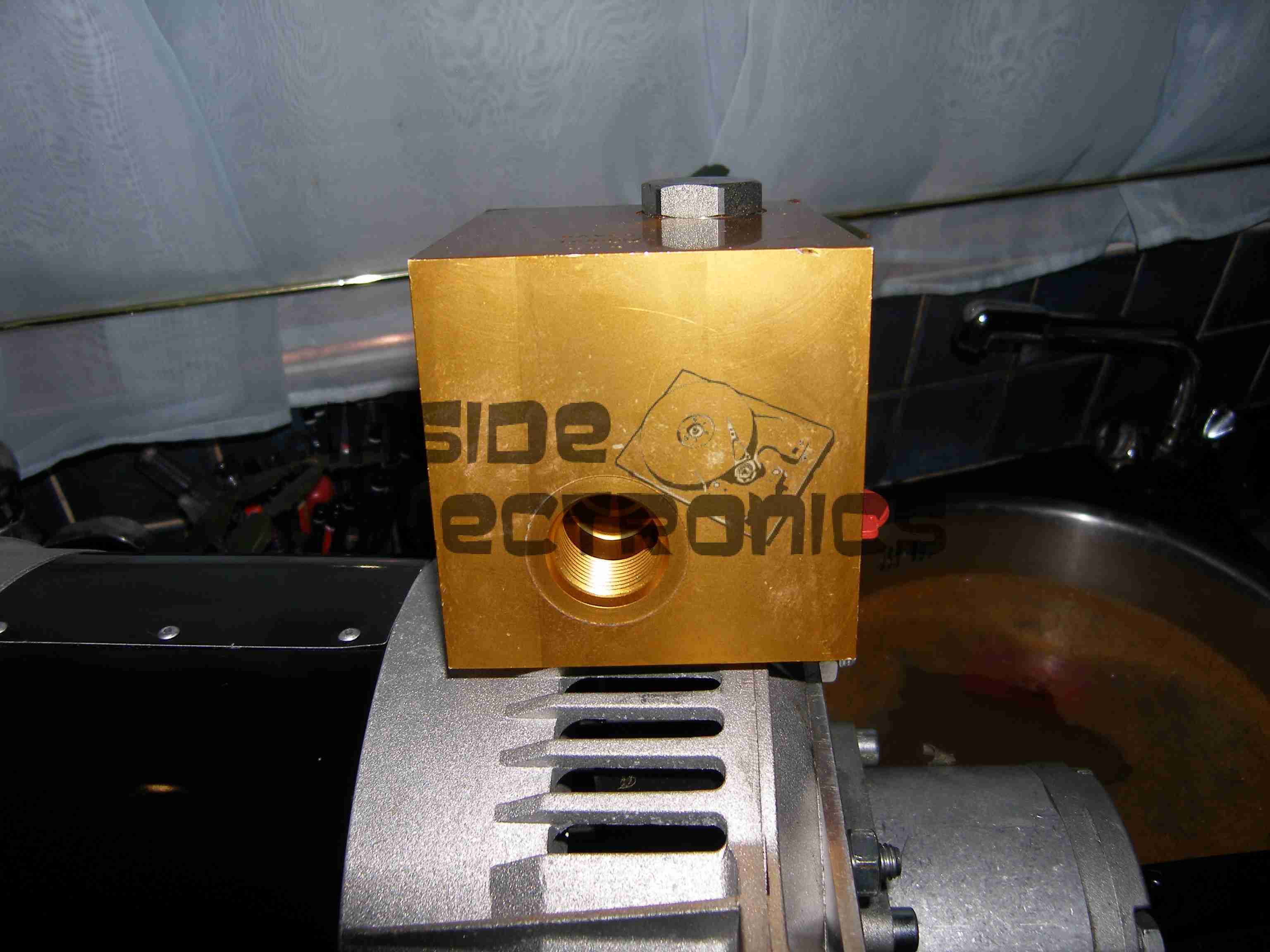
Lining Up The Mountings
Here the pump is being jostled into place. The central hole in the mounting plate is a very snug fit, if the pump doesn’t go in exactly straight it will jam & cause damage to both parts. The mating hole in the coupling hub can be seen here – it’s not quite lined up yet.
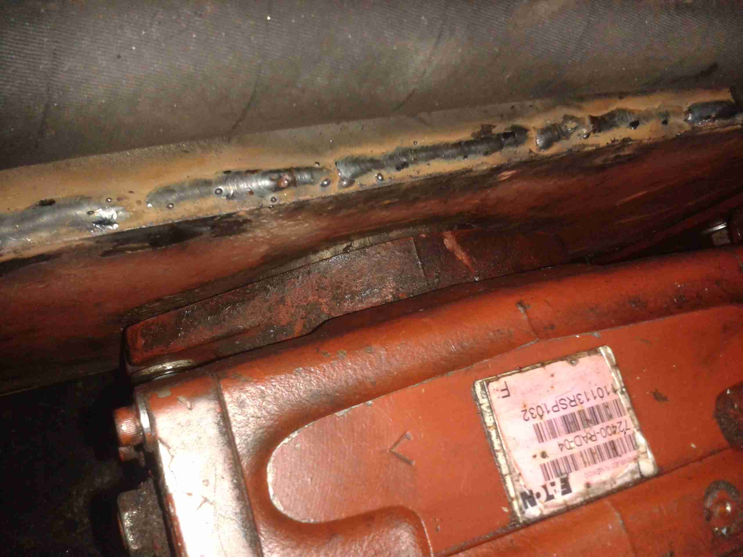
Almost There
We’ve got about 10mm to go before the pump is seated. It’s held in place with a pair of large studs & nuts.
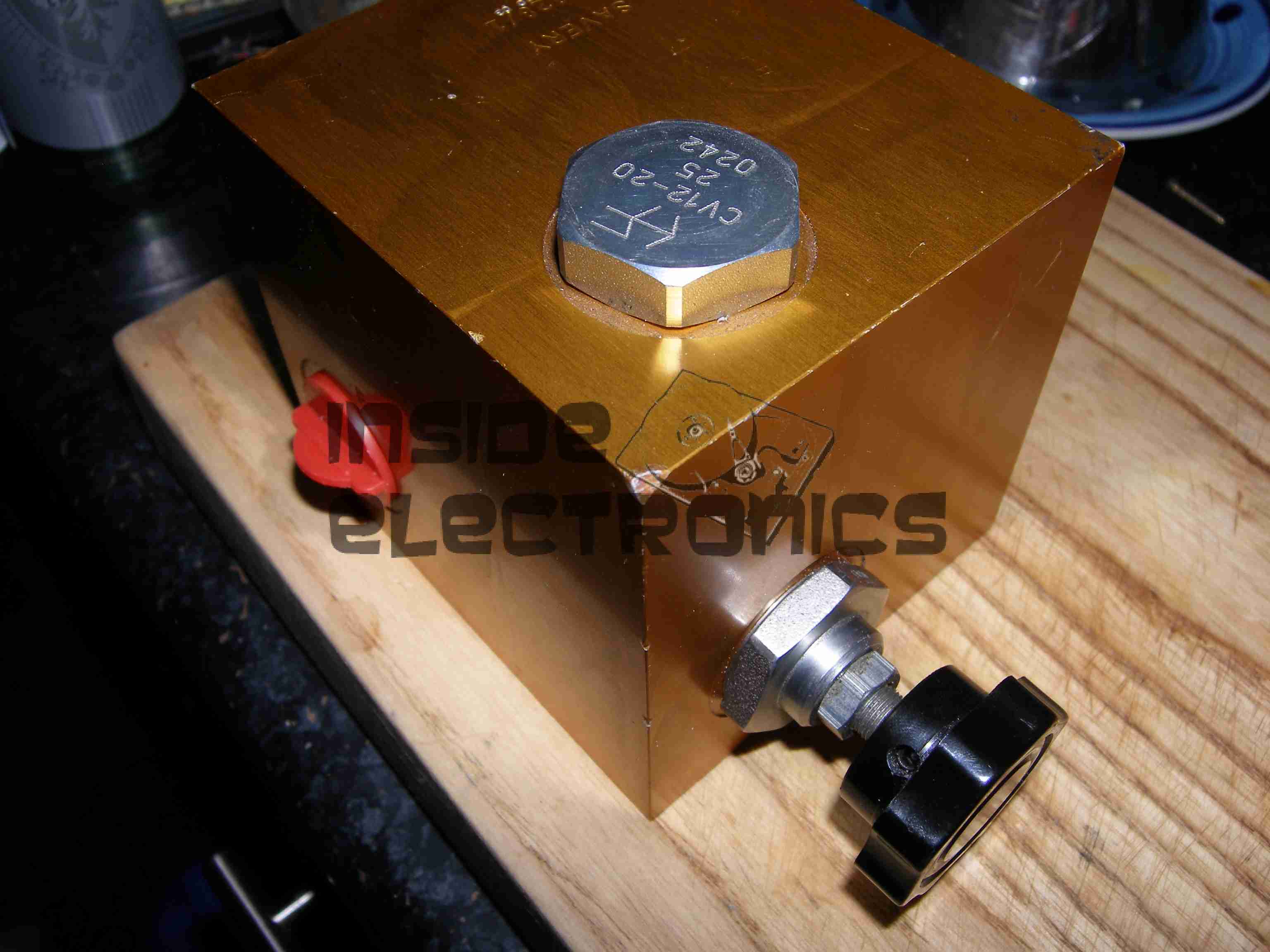
Coupling Connected
Here the pump is fitted enough to get the main mounting bolts into the coupling. These are torqued down to 150ft/lbs – a difficult thing to do considering the restricted space in the engine bay.
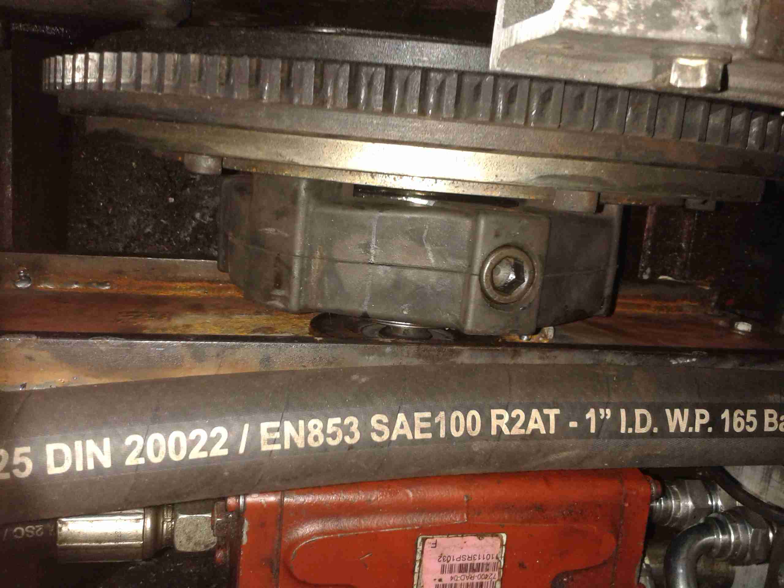
Flush Mounting
The pump has been pulled down onto the plate evenly with the mounting studs, and is now completely flush with the plate. As can be seen, I didn’t bother tidying up the welds with a grinder, they aren’t in any visible place in normal operation, so it didn’t warrant the effort.
Pump Refitted
Finally, the control cable is reattached to the pump’s control lever & everything is installed! A short test trip proved that everything was stable & no undue movement of the pump or coupling was noticed.
I’ve had a couple of viewfinder CRT modules for a while, & haven’t done much with them, so I decided to make a very small B&W monitor.
CRT
I ordered a small transparent ABS box when I made a large order with Farnell, that turned out to be just about the perfect size for the project! The CRT & PCB barely fit into the space. The face of the CRT itself is about 17mm across.
Module Installed
Here’s the main PCB & tube fully installed into the case. Barely enough room for a regulator left over!
Power is provided by a simple LM7809 IC to take a standard 12v input.
Module Rear
Rear of the case, showing the fit of the control board.
Connections
Here’s the back of the monitor, with the DC input jack & a 3.5mm 4-pole jack for audio & video. This allows simple connection to many devices, including the one I’ll use the most – the Raspberry Pi.
Completed
Completed monitor. Audio is handled by a very small 20mm speaker, currently mounted just below the CRT face.
Current draw from a 13.8v supply is 117mA.
From the factory, the GY561 meter uses alkaline AAA cells for power. As these are not rechargable, and I don’t carry any other devices that take such batteries, I figured I’d replace them with a single Lithium Polymer cell that I can charge via USB.
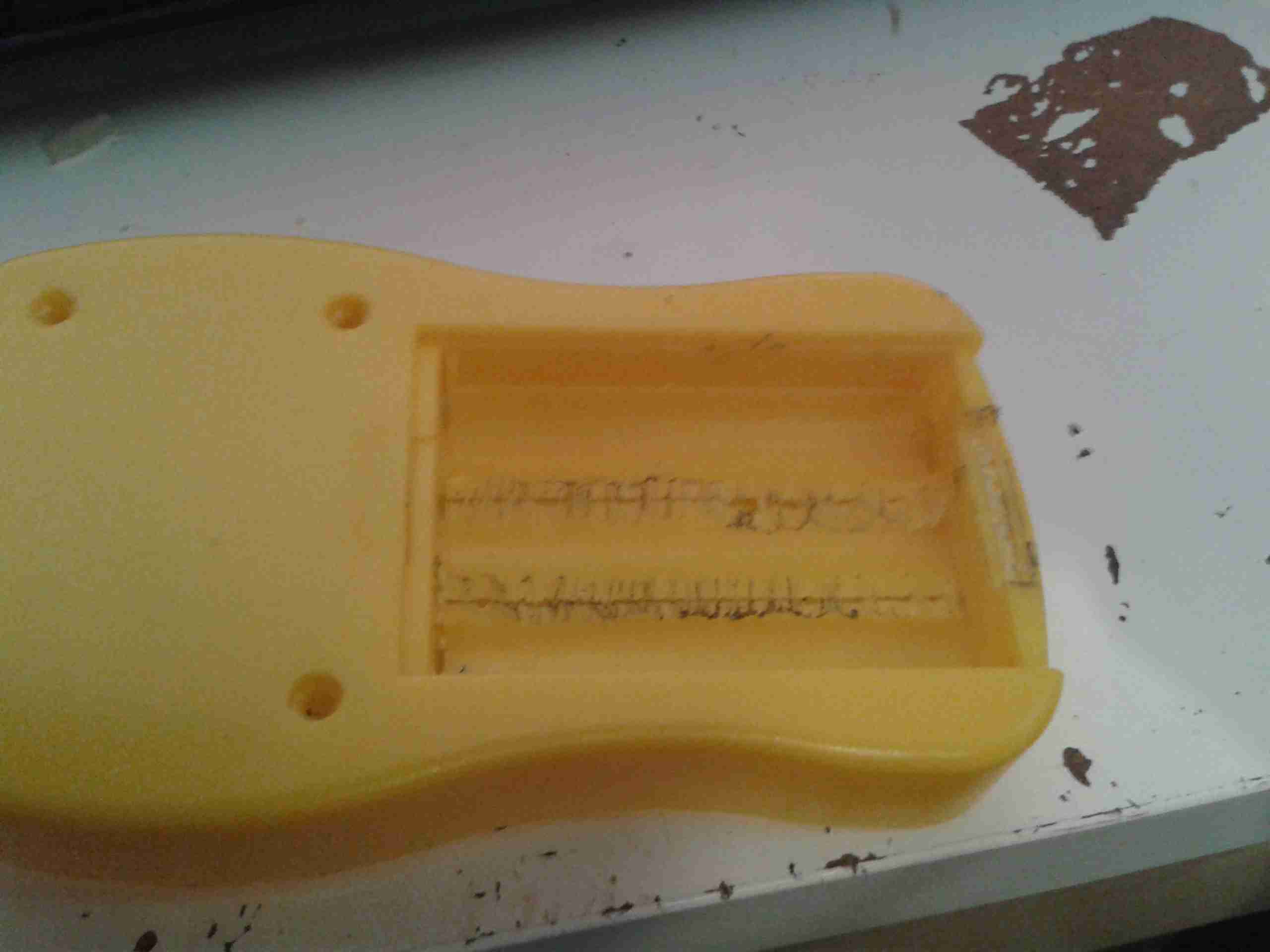
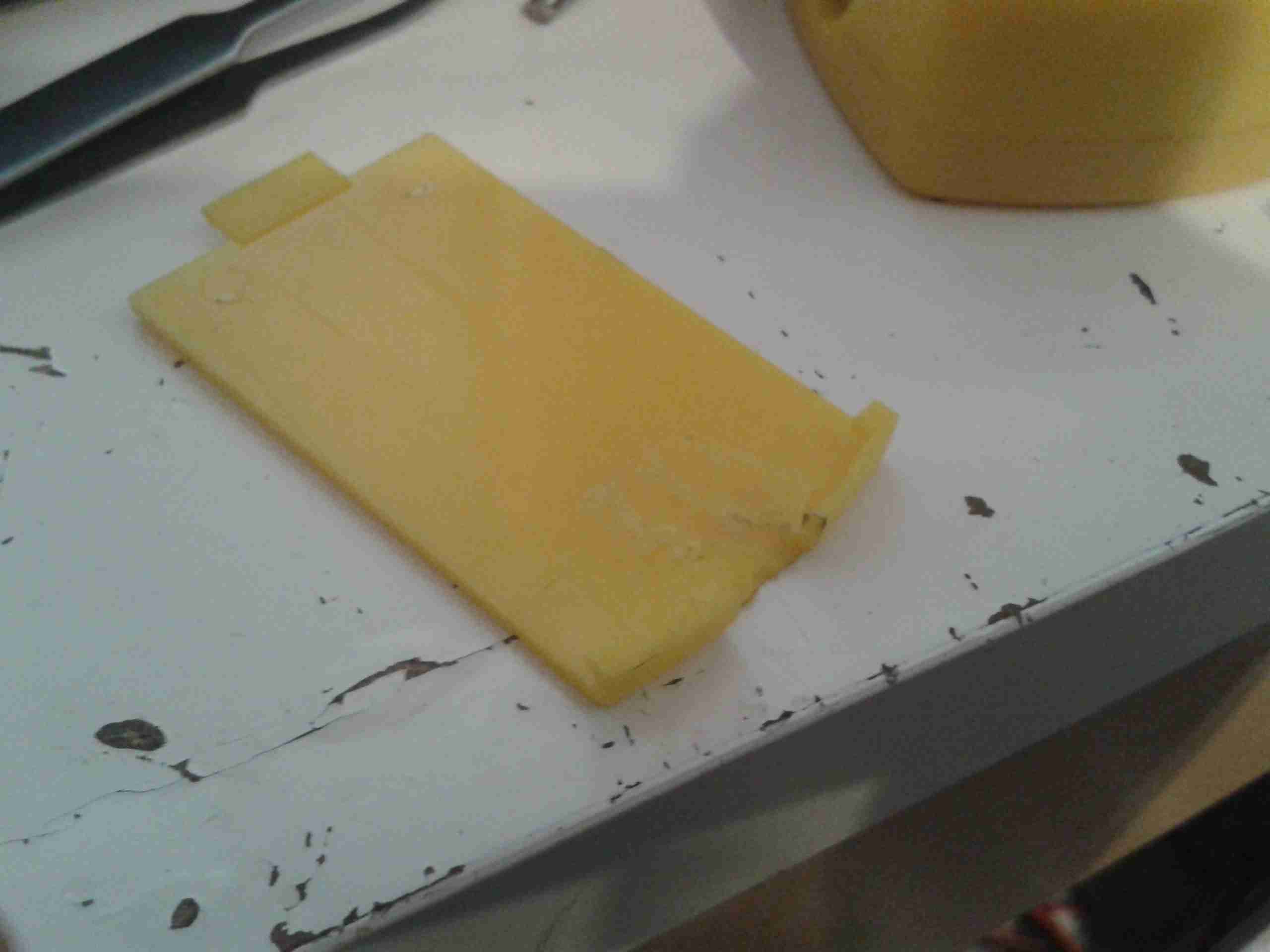
Battery Compartment
Here’s the battery compartment, with the original spring terminals removed.
I searched eBay for a suitable sized cell, and settled on a 1000mAh type, with dimensions of 47mm x 28mm x 7mm.
This size cell required a small amount of modification to the battery compartment to make it fit properly with the associated charge & protection circuitry.
Modified Compartment
Here’s the modifications made to the compartment, I’ve ground away the plastic to make the bottom flat, and the plastic tabs that retained the original spring terminals.
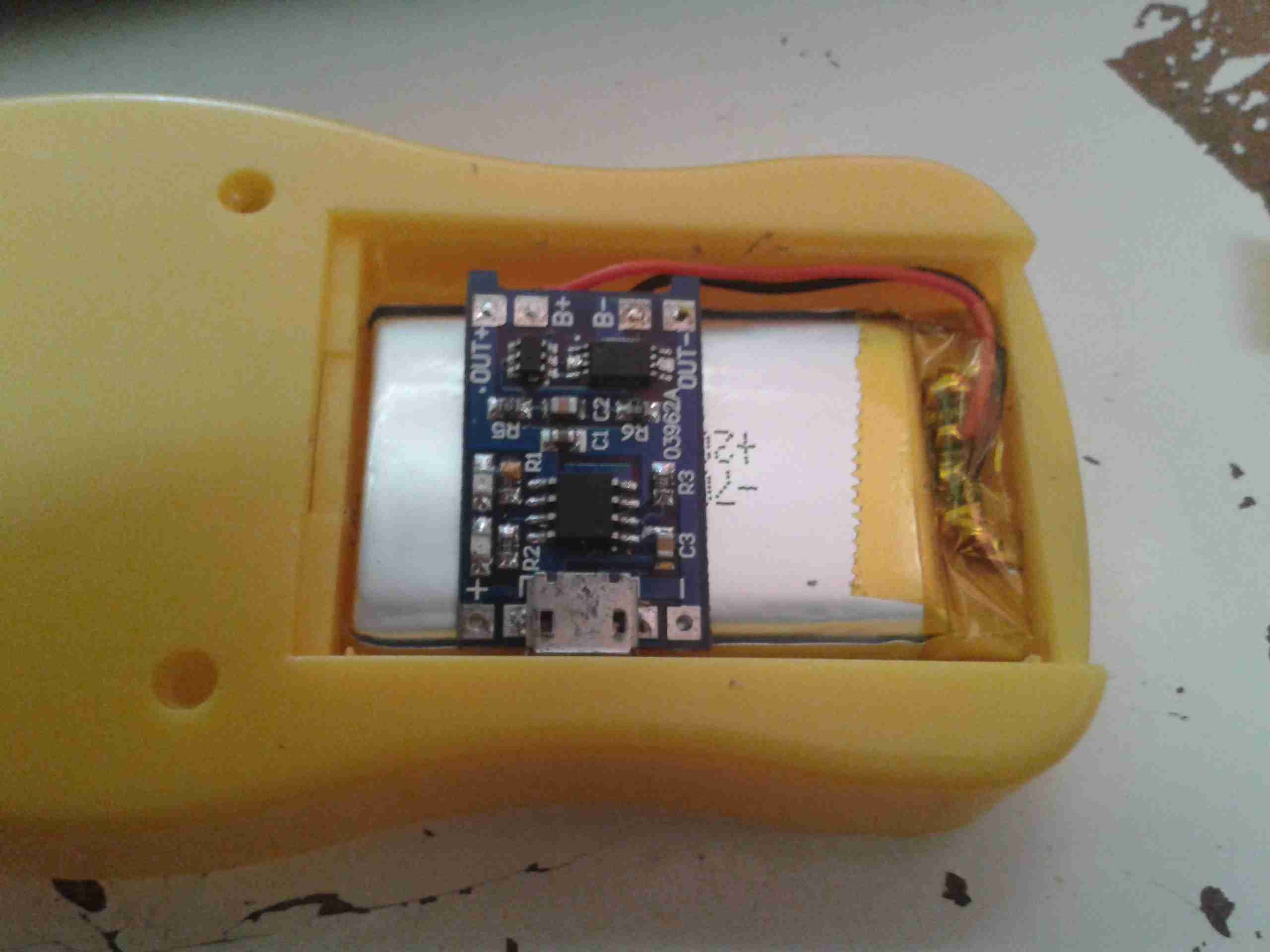
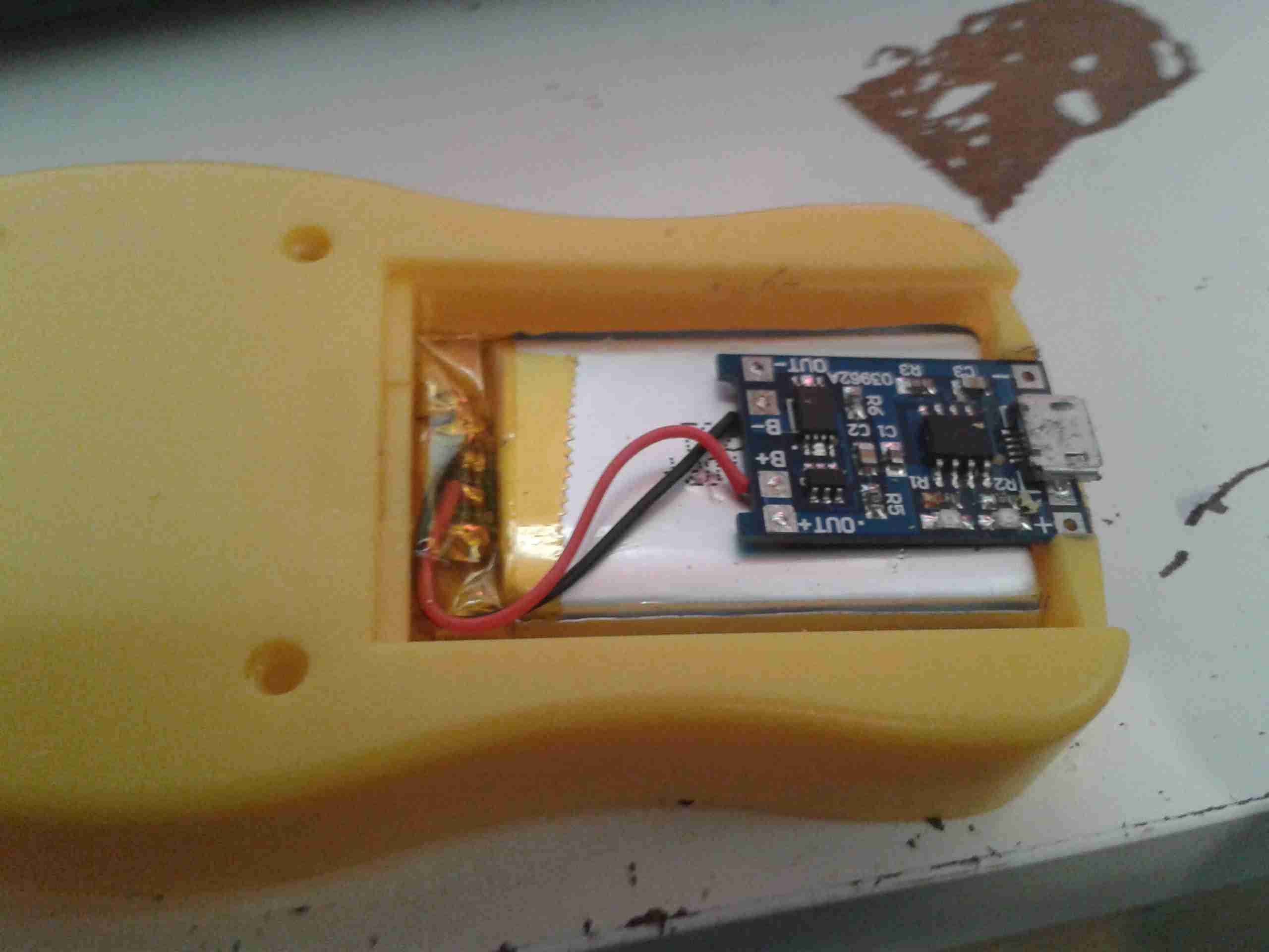
Modifications
After grinding away the original battery spring holders with a dremel, the cell fits perfectly in the available space. The small PCB on the top of the cell is the USB charger & protection.
Charger
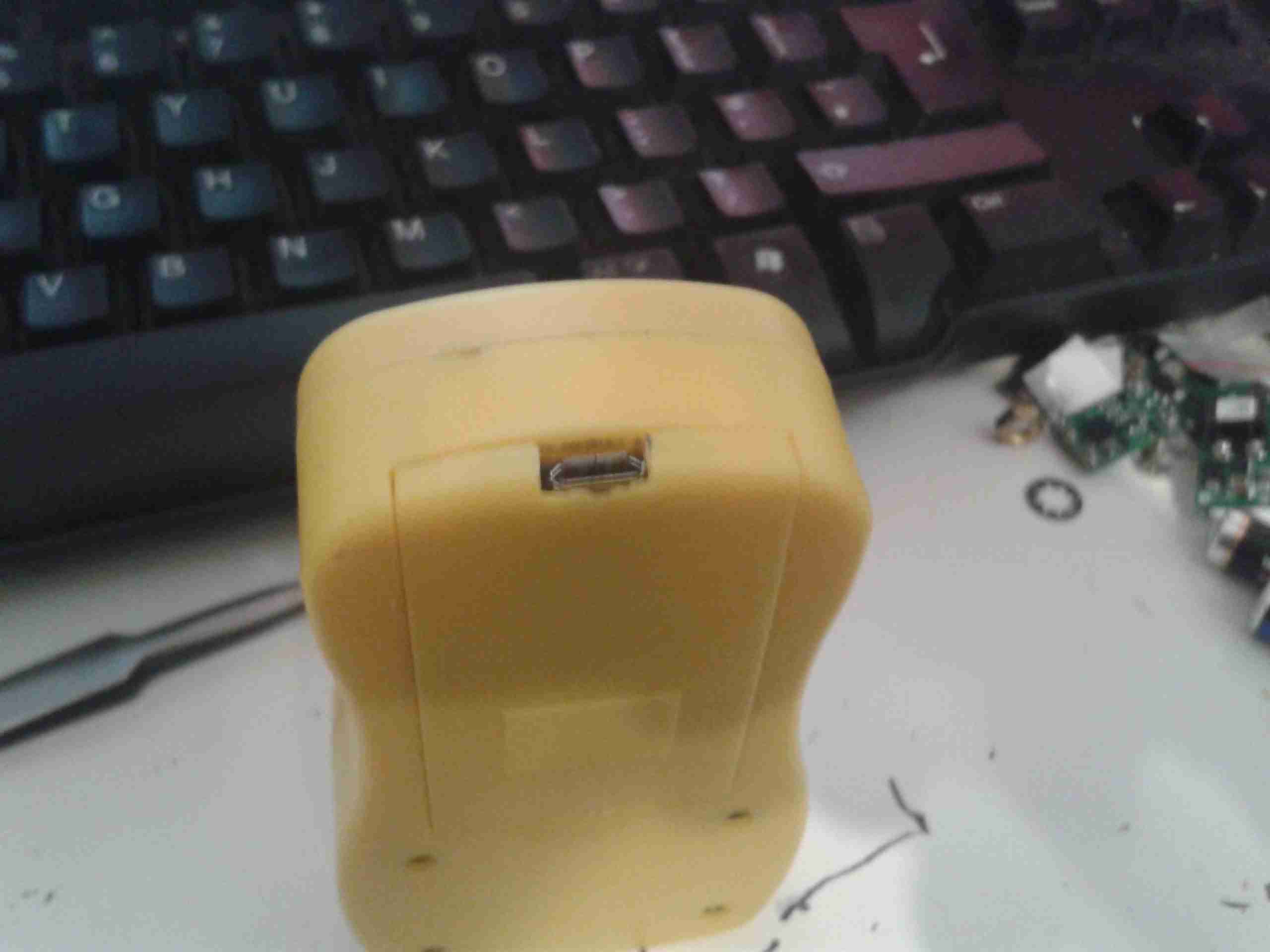
The charger is located in a slot cut in the bottom of the casing, so the USB port is accessible from outside the compartment.
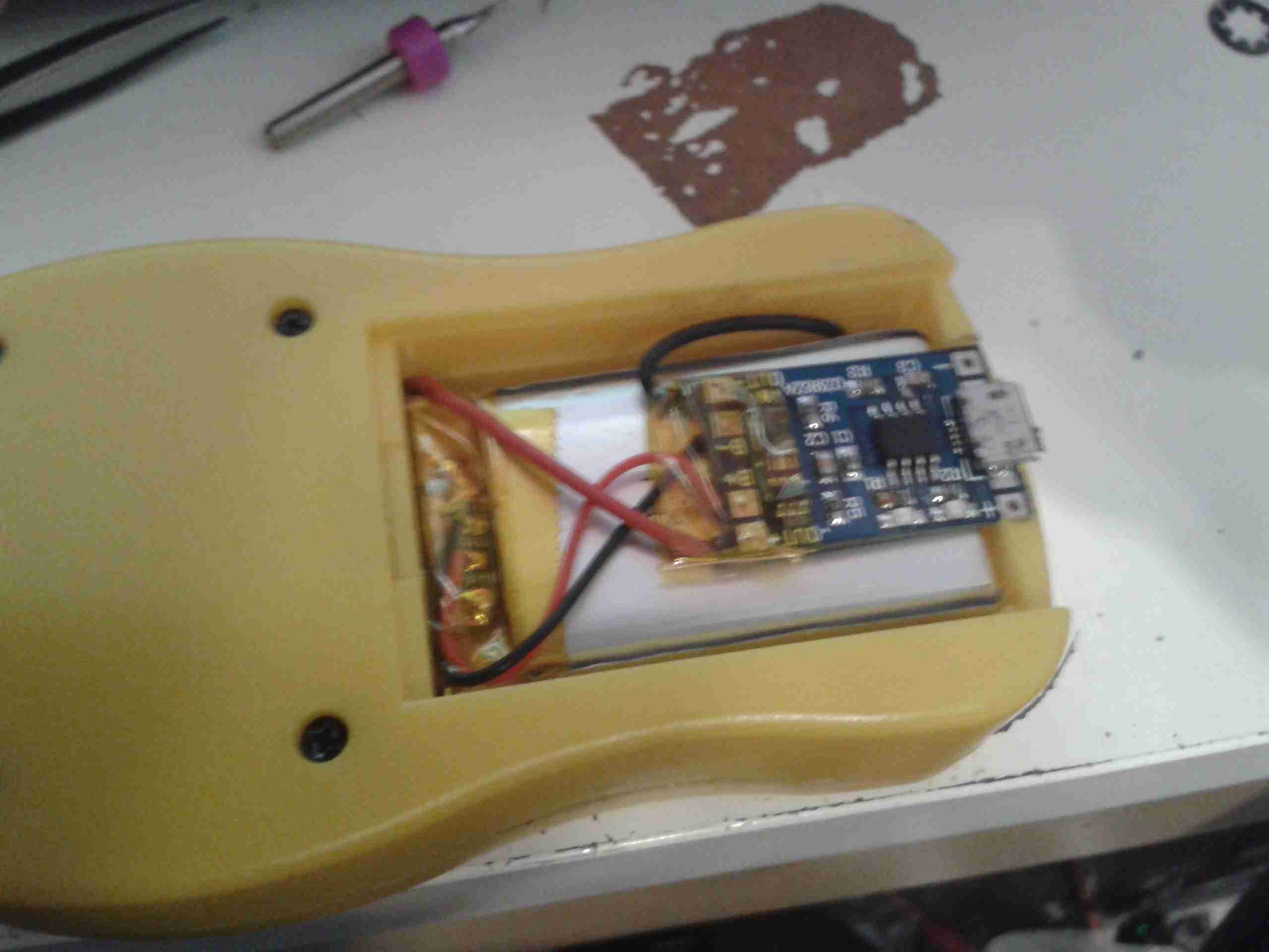
Wiring
Here’s the rest of the wiring completed, with the power wires going through holes in the bottom of the battery compartment to join onto the PCB where the original terminals were located. I have insulated the solder joints on the control PCB with some Kapton tape to prevent any shorts against the lithium cell.
Battery Cover
A small cutout was also required in the battery cover to allow the USB connector to poke out. This was easy to do on the soft plastic with a Dremel tool.
Charging Port
With the battery cover installed, the USB port is nicely recessed into the edge.
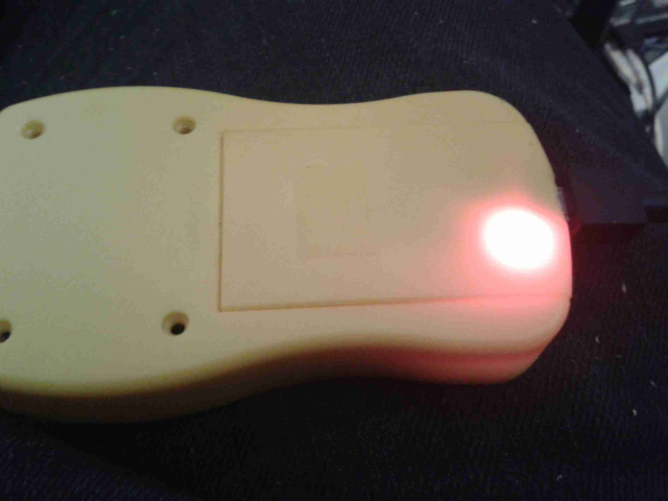
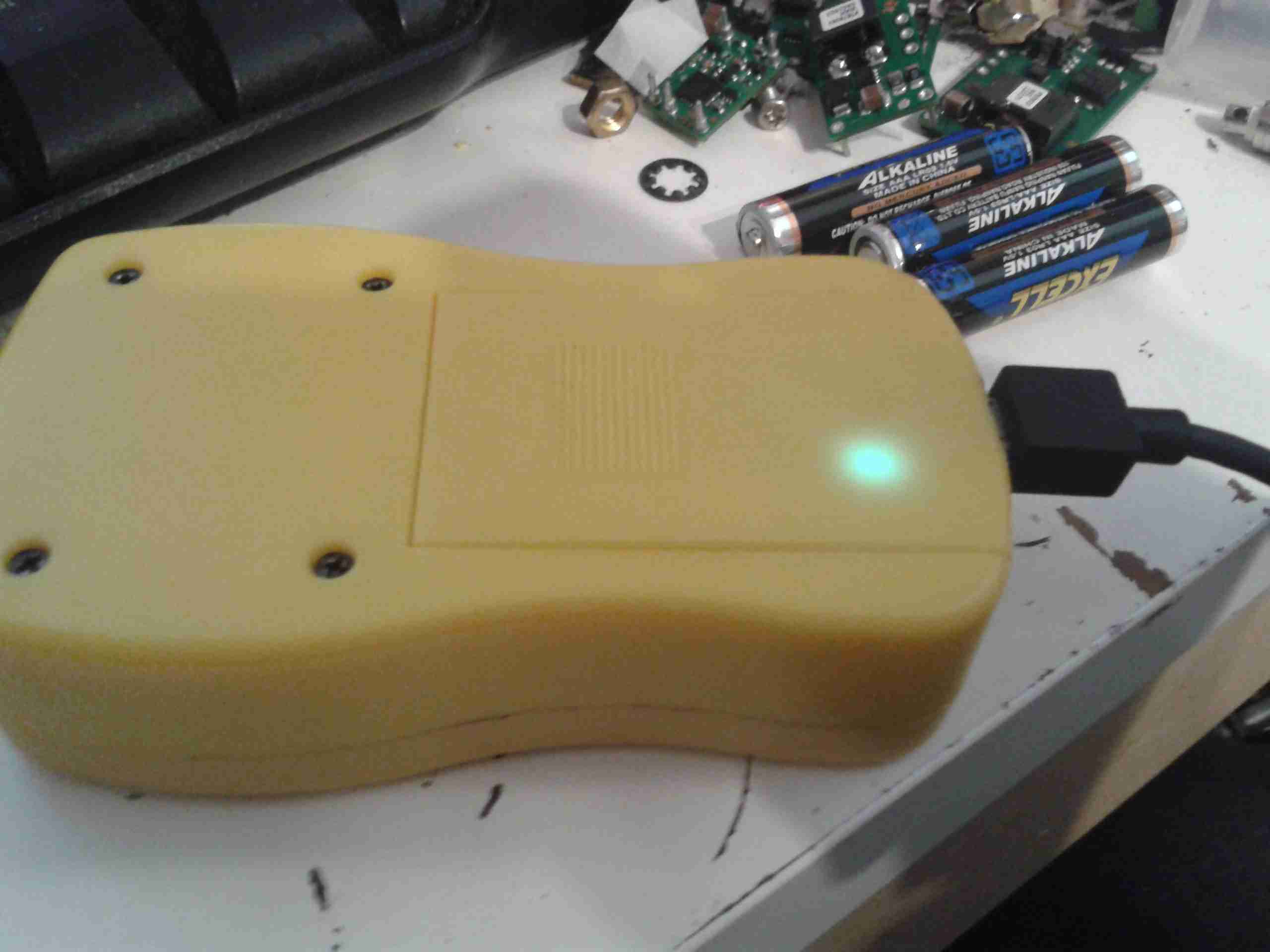
Charging LED
The indicator LEDs on the charging & control board show nicely through the plastic, here’s the unit on charge. When the charge is complete, another LED lights as shown below.
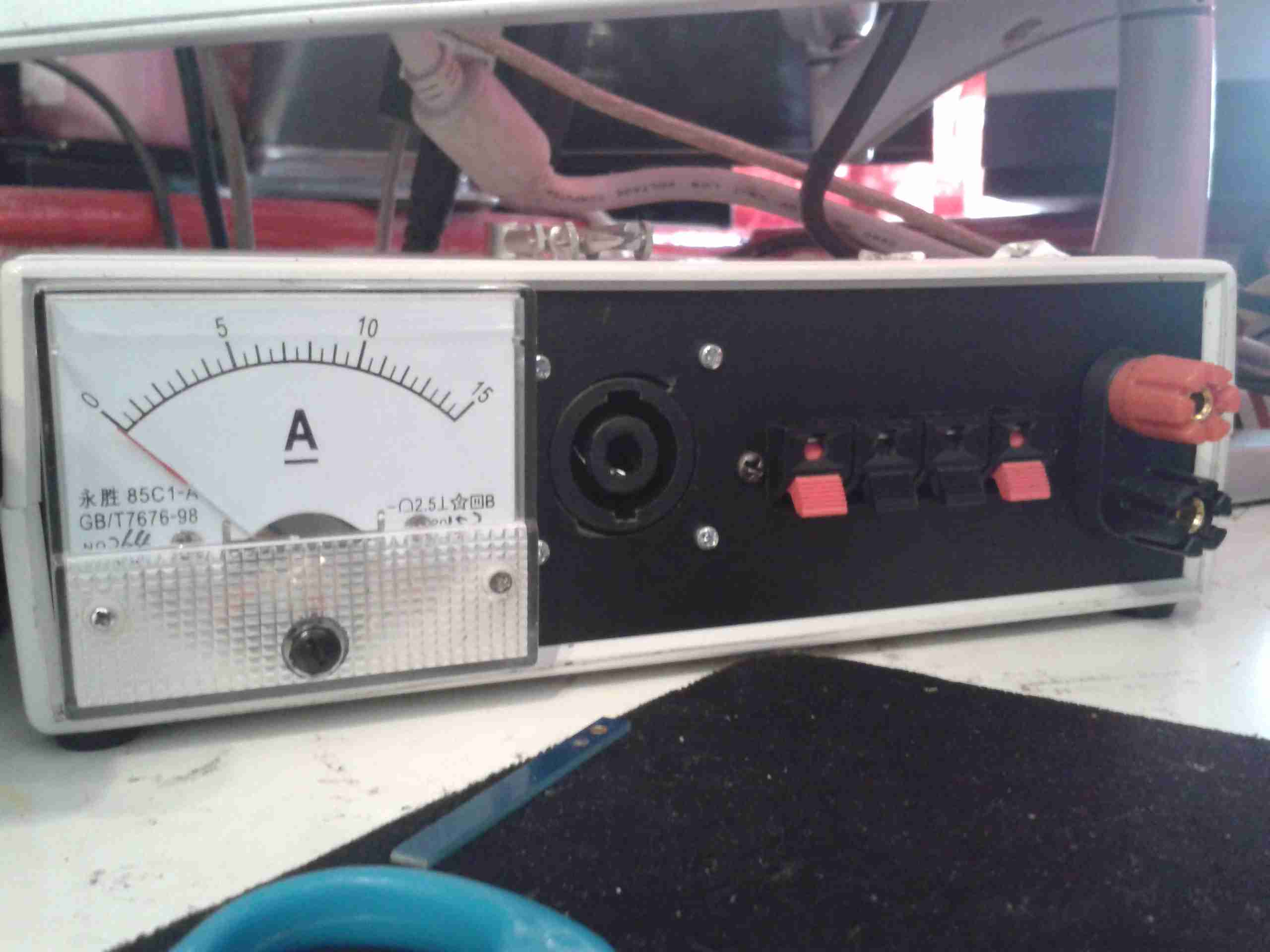
Following on from my recent power supply build, I’ve added on a couple of improvements:
Front Panel
I’ve added on my standard SpeakOn type 30A connector, a bank of push terminals for quick connecting test leads, and a 15A FSD ammeter.
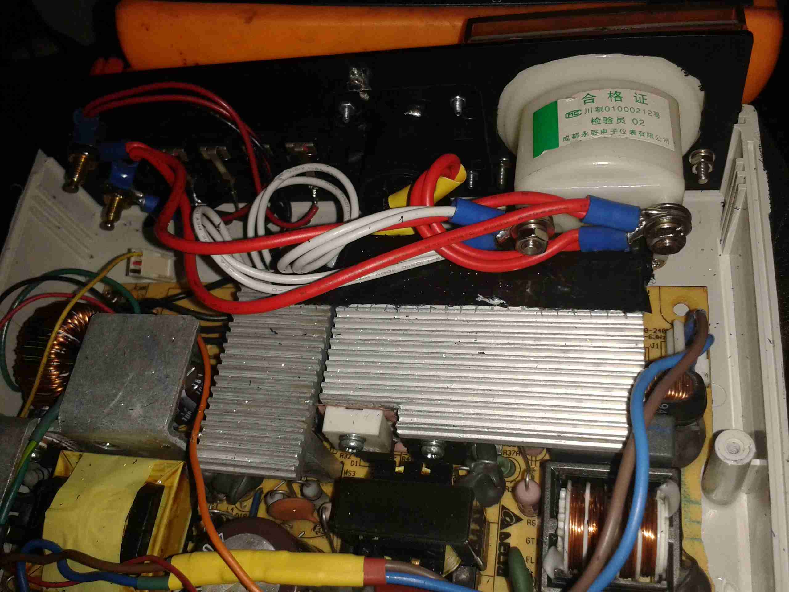
Panel Rear
Due to the limited space inside the supply, I’ve had to improvise some insulation on the mains-side heatsink to prevent a nasty accident. The heatsinks are tied to the supply’s HVDC bus negative, so they are energized at -145v DC relative to mains earth. This fact has given me a nasty surprise! The insulation is several layers of Kapton tape, with a couple of layers of Duct Tape. This along with trirated wire to the SpeakOn & the panel meter should ensure safety.
The Ammeter itself was sourced from eBay, for £2. It seems pretty accurate so far!
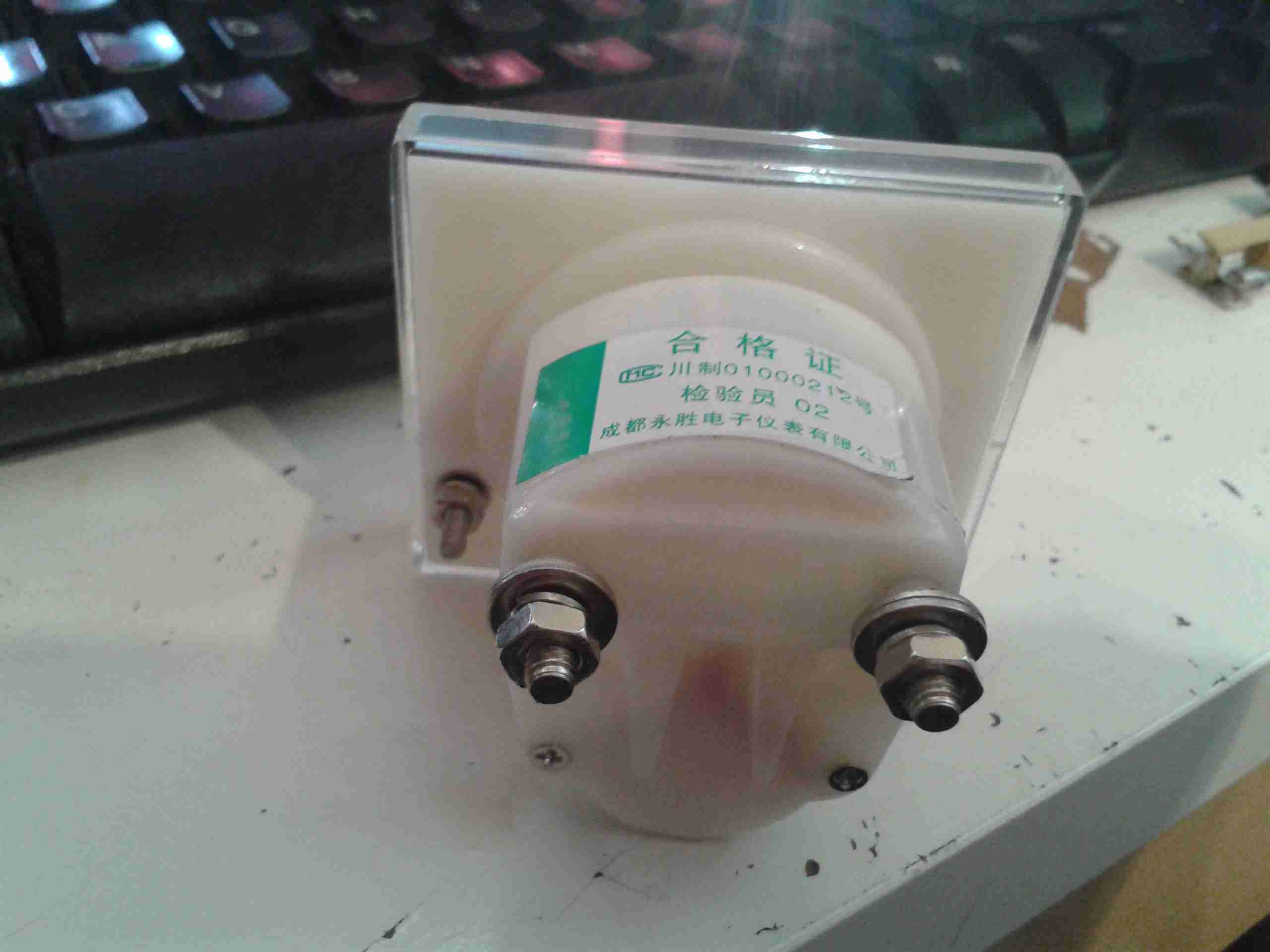
Ammeter
The shunt is built into the rear of these meters, in an ultrasonically welded part of the case, so I can’t examine it. Hopefully it is indeed rated to 15A!
The only things left to make this supply complete are a mains power switch, and a fan speed control, as the fan I have used is a little noisy at full speed. It will be good to get the speed based from the internal temperature, so the fan only runs at full speed when the supply is under load.
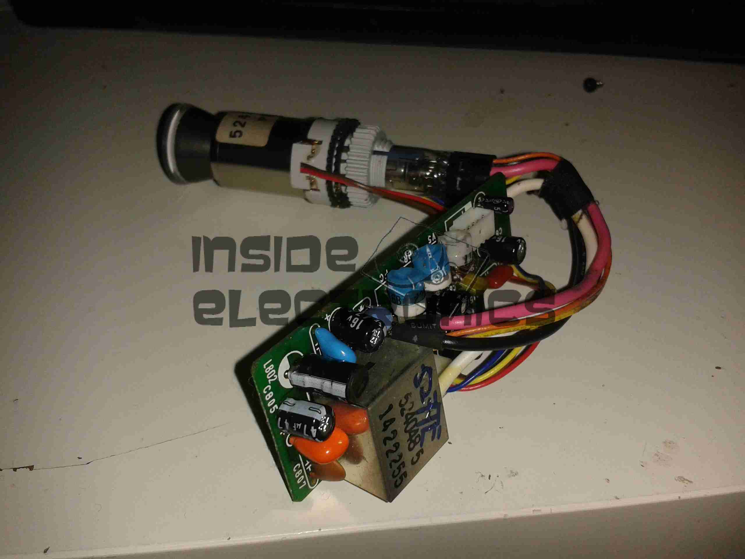
Here’s another viewfinder CRT, removed from a 1980’s vintage VHS camera I managed to get cheap from eBay.
This unit is very similar to the last one I posted about, although there are a few small differences in the control circuitry.
Viewfinder Schematic – Click to Embiggen
Here’s the schematic, showing all the functional blocks of the viewfinder circuitry. An integrated viewfinder IC is used, which generates all the required scan waveforms for the CRT.
On the left is the input connector, with the power & video signals. Only pins 2 (GND), 3 (Composite video), & 4 (+8v) are needed here. Pin 1 outputs a horizontal sync signal for use elsewhere in the camera, while pin 5 fed the recording indicator LED.
To make connection easier, I have rearranged the wires in the input connector to a more understandable colour scheme:
Input Connector
Red & Blue for power input, & a coax for the video. For the video GND connection, I have repurposed the Rec. LED input pin, putting a shorting link across where the LED would go to create a link to signal ground. Keeping this separate from the power GND connection reduces noise on the CRT.
Viewfinder CRT Assembly
Here’s the complete assembly liberated from it’s plastic enclosure.
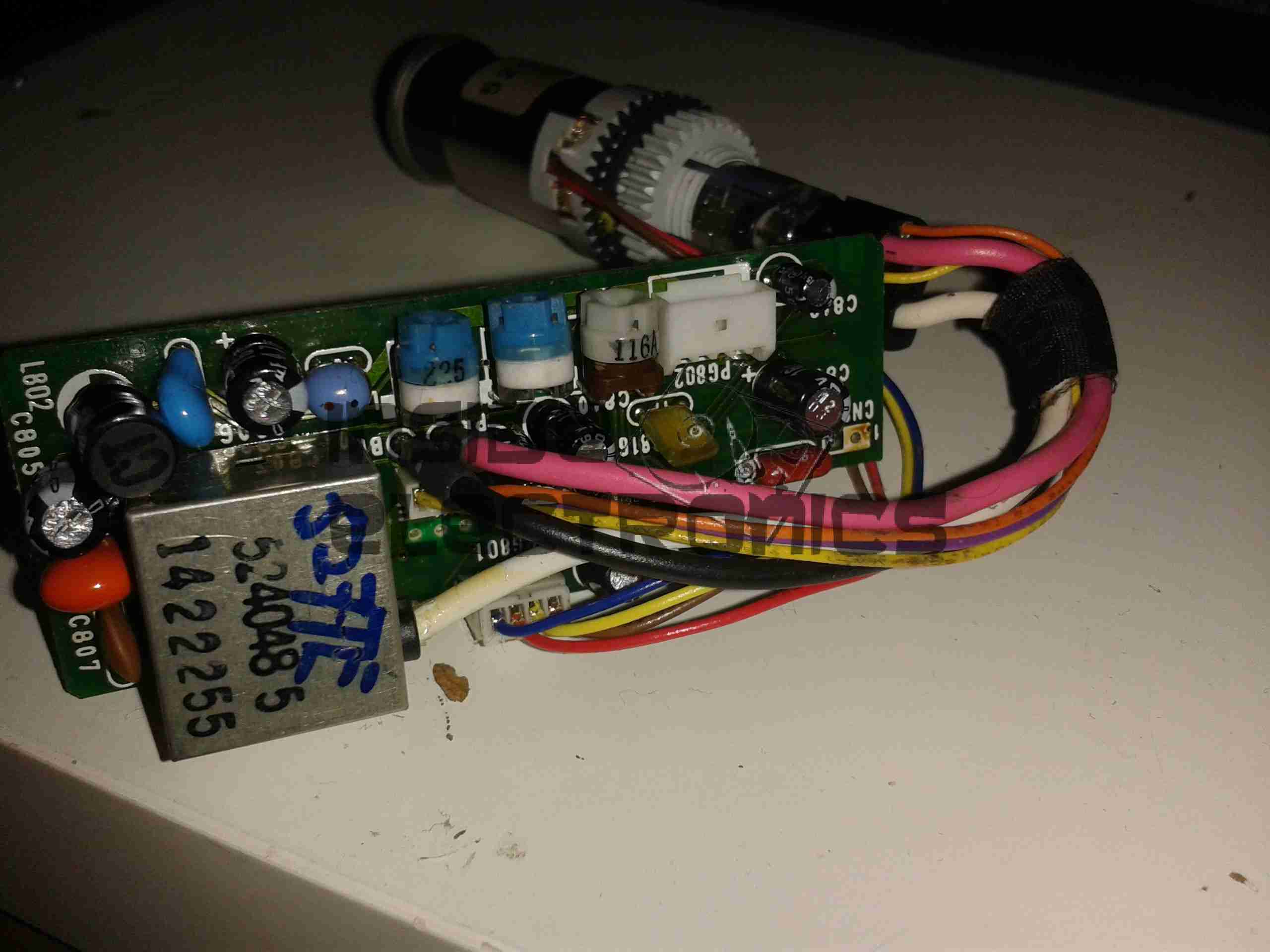
PCB Closeup
Closeup of the control PCB. The 3 potentiometers control the CRT brightness, focus & vertical size.
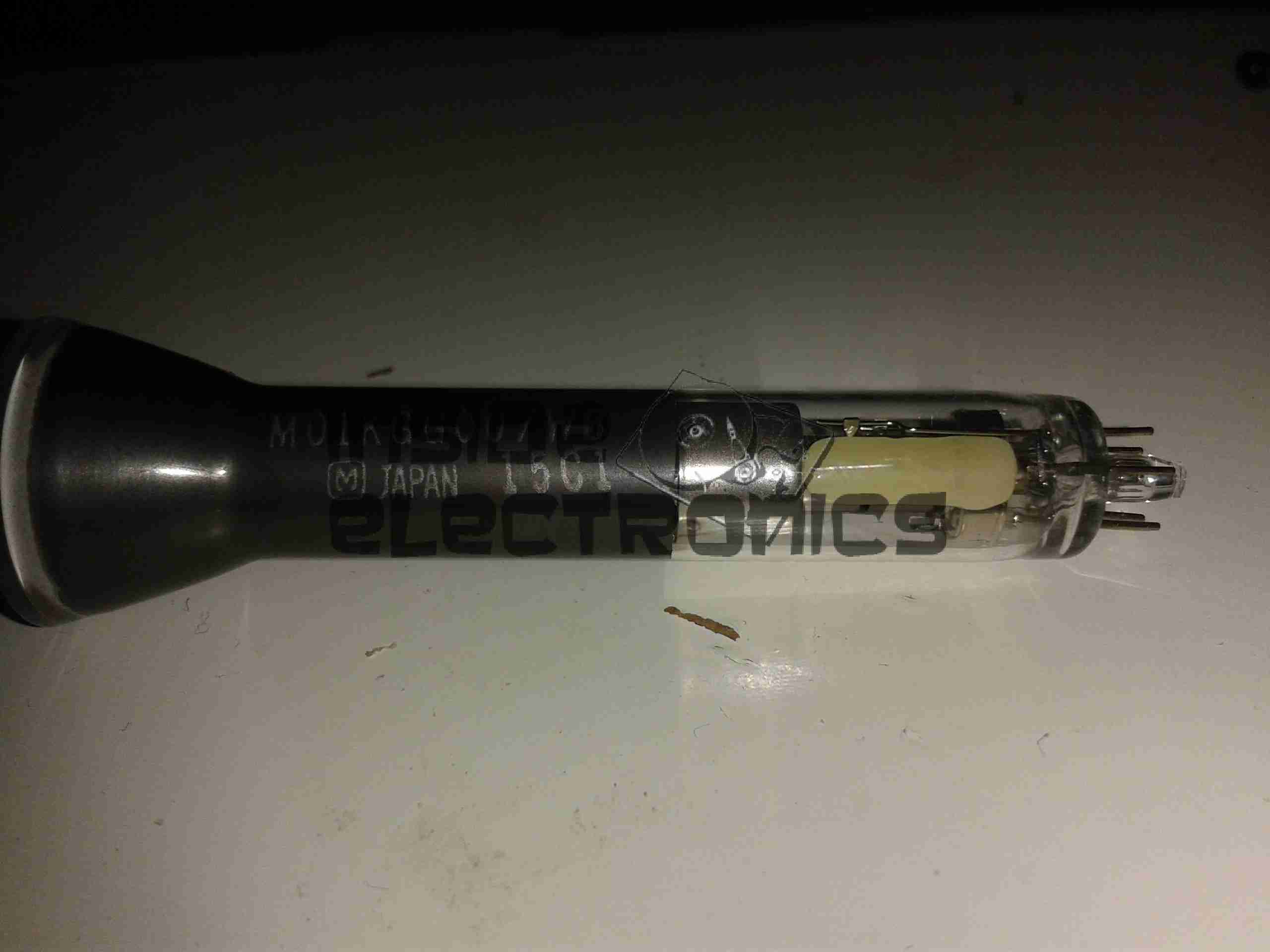
M01KGG007WB CRT
The tiny CRT. Only ~60mm in length, with an 18mm screen size. This tube runs on +2294v final anode voltage. Much higher than I expected.
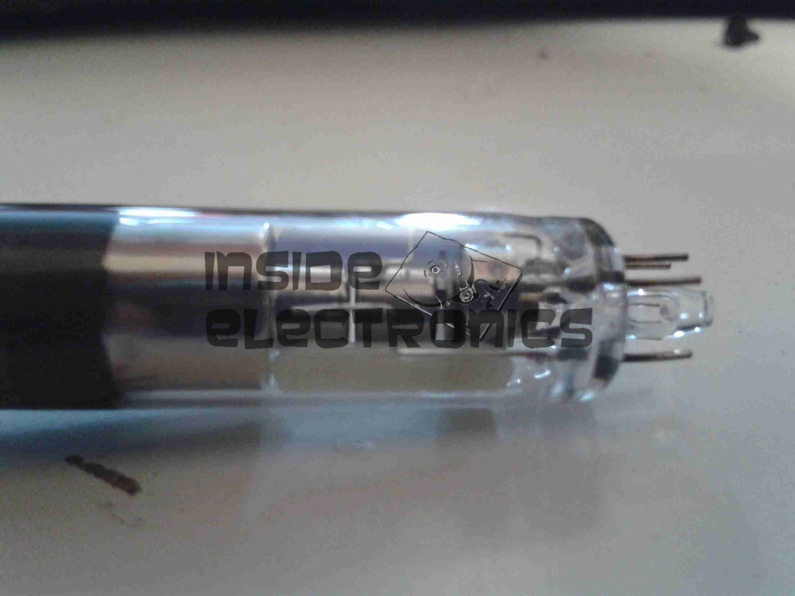
Electron Gun Closeup
The electron gun assembly, with the cathode, focus & final anode cups.
Phosphor Screen
This screen is just a little bigger than a UK 5p piece! A marvel of precision engineering.
Regular readers might remember a previous post about the fiasco we have had with a hydraulic generator, and in particular one person by the name of Mike Webb.
Well here we are a year down the line. The generator still doesn’t function properly, as other things have taken priority, but this is being remedied this week with a replacement hydraulic powerhead. (Correctly sized to 6cc this time, not 11cc).
I even finally got a response from Mike, most likely due to my previous post & the negative publicity that would have brought. In July Mike wrote this:
Good Morning Ben,
I have read your article on the above website, not entirely sure what I can say.
I do however sincerely apologise for the way I handled things, I could give numerous reasons, but I guess they are not your concern, I behaved badly and I am disappointed in myself for treating anyone in this way.
The business has now folded, the domain name www.hydraulicgenerators.co.uk and related products are now owned, manufactured and sold by another company.
My only hope now is that I can in some way repair the damage that has been done and hope that somewhere within yourself you can find a way to accept my apology and forgive me, I am genuinely not a bad person but circumstances outside of my control at the time led me to act in an inacceptable way.
I can understand how you feel, I was defrauded out of a considerable amount of money a while ago and seeking revenge has not been far from my mind for a considerable time, but it won’t get my money back, it won’t undo the damage that has already been done and whilst I might feel better about it for a short while, I have found it difficult from a personal perspective, as, whilst you may cast aspersions about me, my conscience and I do have one just won’t allow me, I can’t help myself from thinking of the other people that would be impacted upon that are otherwise innocent and I know in this particular instance there are several.
I can only hope that you accept my most sincere apology.
Right then. Where should I begin.
No Mike, I will never EVER forgive someone for, what was in my eyes, a deliberate act of fraud & a complete refusal to co-operate.
Now, being the resourceful person I am, and my ability (like anyone else with brains), to find out the registrar of domain names, have discovered the man is yet again lying. Company folded? I think not my son.
Two other domain names have popped up with Mike’s name on the Registrar details: ukgenerators.co.uk
shop4generators.co.uk
(For completeness, here are the full registrar details, just in case things change after I publish this. This information is correct as of 9/12/14)
Domain name: ukgenerators.co.uk
Registrant: Mike Webb
Registrant type: UK Individual
Registrant’s address: <REDACTED>
Data validation: Registrant contact details validated by Nominet on 10-Dec-2012
Relevant dates: Registered on: 02-Jun-2005 Expiry date: 02-Jun-2015 Last updated: 27-Jun-2013
Registration status: Registered until expiry date.
Name servers: ns1.hostpapa.com ns2.hostpapa.com
WHOIS lookup made at 16:55:43 09-Dec-2014
Now for someone who is obviously attempting to tell me that he has no money or resources to reimburse us for the utter hell we have been put through in this situation, seems to be doing pretty well for themselves, in the same business that has apparently ‘folded’.
You have a shiny new logo & business name, and yet apparently have ceased trading?
Now, having been part of a firm during a takeover/company sale, domain names are usually immediately transferred into the name of the buying company. Not in this case it seems. All domains are still registered to you.
Your LinkedIn account still has you as being in the business, along with your Twitter account & YouTube account.
Not to mention, that one one of the aforementioned sites (the original hydraulicgenerators.co.uk), Mike’s E-Mail address is still very much visible on the front page E-Mail Link!
If this is the case, then Mike Webb is in fact operating illegally.
Mike, if you do read this, I AM NOT AN IDIOT. All I asked was that you put things right, so we would have a WORKING GENERATOR.
So far all this has cost is time & money, and I certainly don’t like being conned.
However I feel it is my duty to make sure that anyone who ever has the misfortune of dealing with you knows exactly what you have previous form for doing.
Legal notice:
All information contained in this post is correct as of 9/12/14. Information will be kept up to date & factually correct to the best of my ability.
Stay tuned for the final chapter in getting this generator fitted & working.
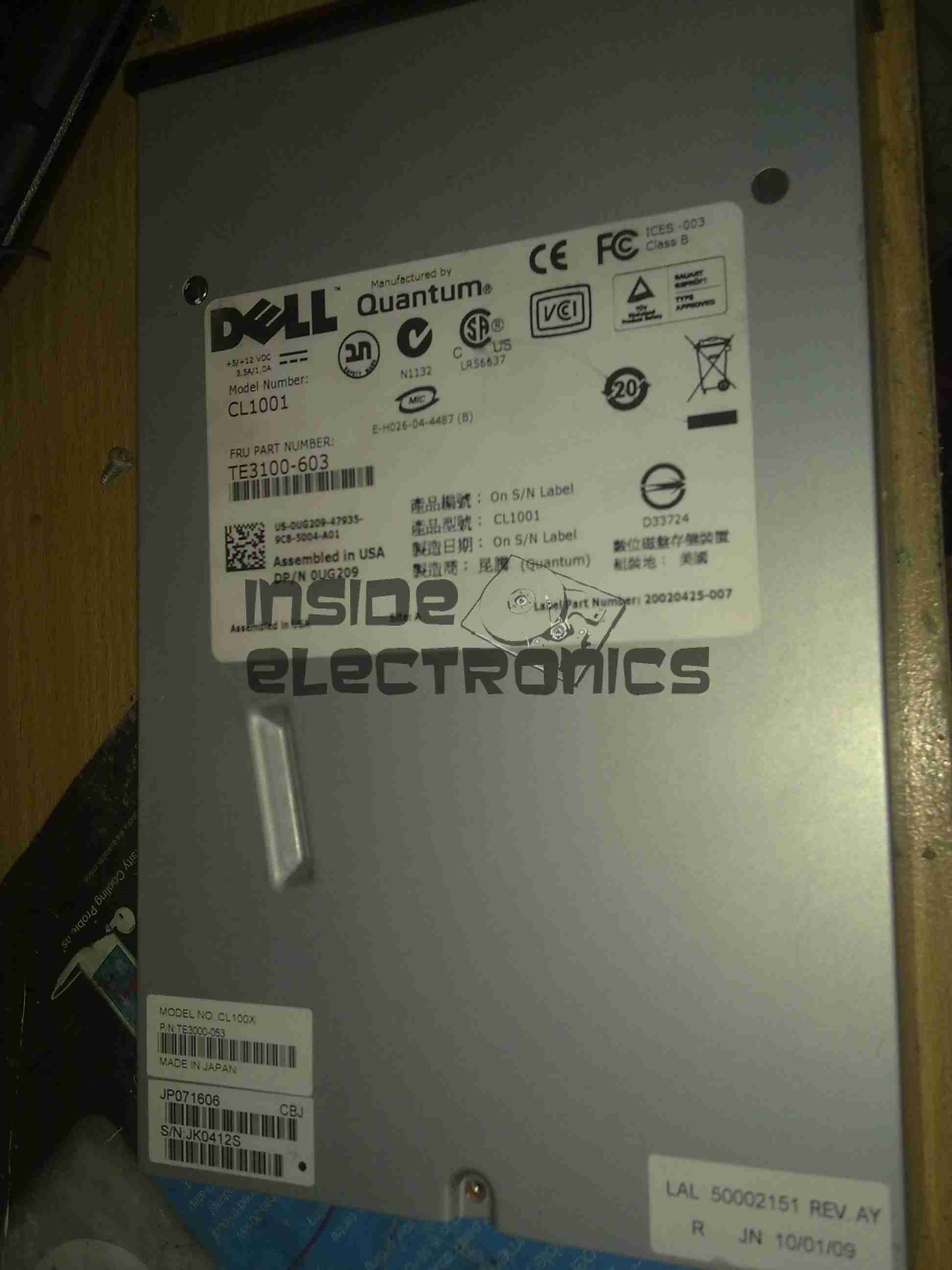
I have recently begun to create an archive of all my personal data, and since LTO2 tape drives offer significant capacity (200GB/400GB) per tape, longevity is very high (up to 30 years in archive), & relatively low cost, this is the technology I’ve chosen to use for my long term archiving needs.
Unfortunately, this drive was DOA, due to being dropped in shipping. This drop broke the SCSI LVD connector on the back of the unit, & bent the frame, as can be seen below.
Broken SCSI
As this drive is unusable, it made for a good teardown candidate.
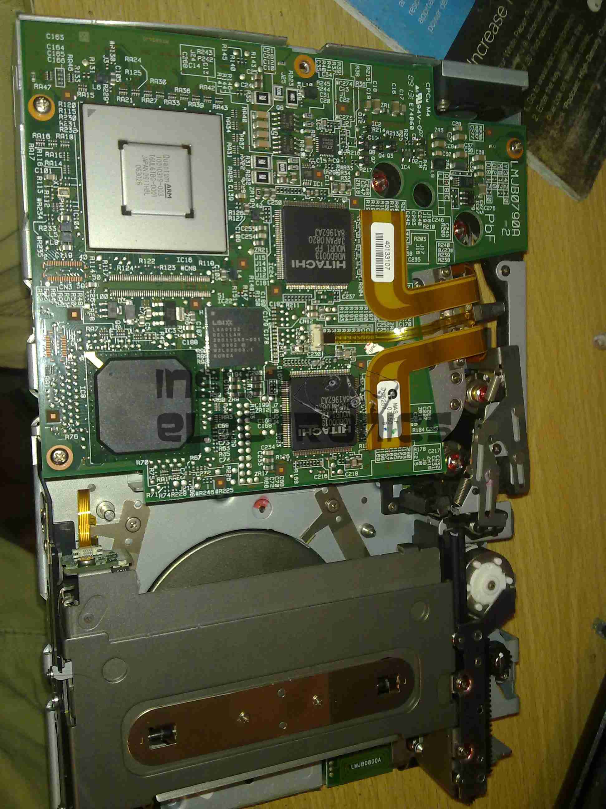
Cover Removed
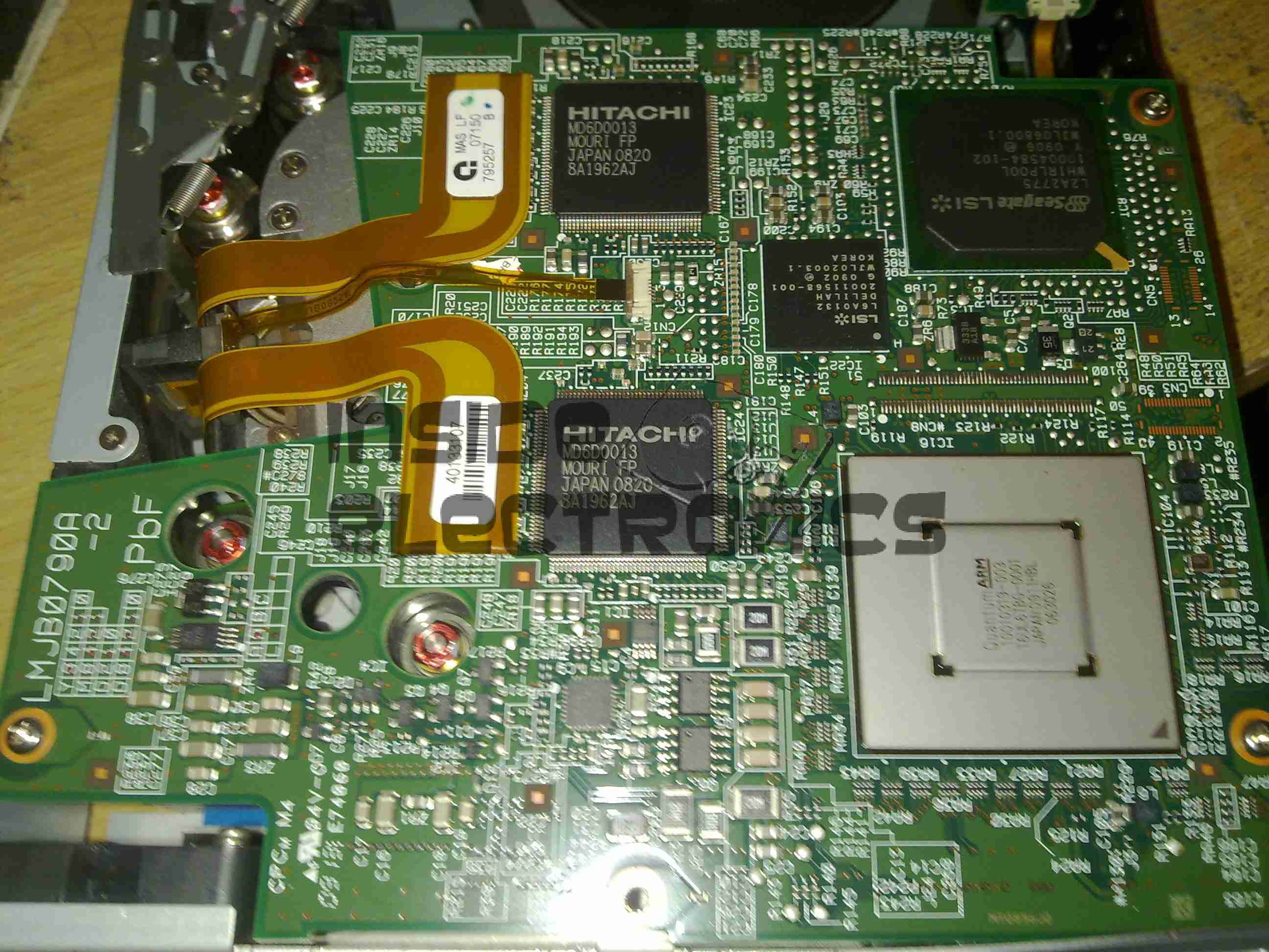
Here the top cover of the drive has been removed, showing the top of the main logic PCB. The large silver IC in the top corner is the main CPU for the drive. It’s a custom part, but it does have an ARM core.
The two Hitachi ICs are the R/W head interface chipset, while the smaller LSI IC is the SCSI controller.
The tape transport & loading mech can be seen in the lower half of the picture.
Main Logic
Close up of the main logic.
Tape Spool
Here the main logic PCB has been removed, showing the tape take up spool. The data cartridges have only one spool to make the size smaller. When the tape is loaded, the drive grabs onto the leader pin at the end of the tape & feeds it onto this spool.
The head assembly is just above the spool.
Bottom Plate Removed
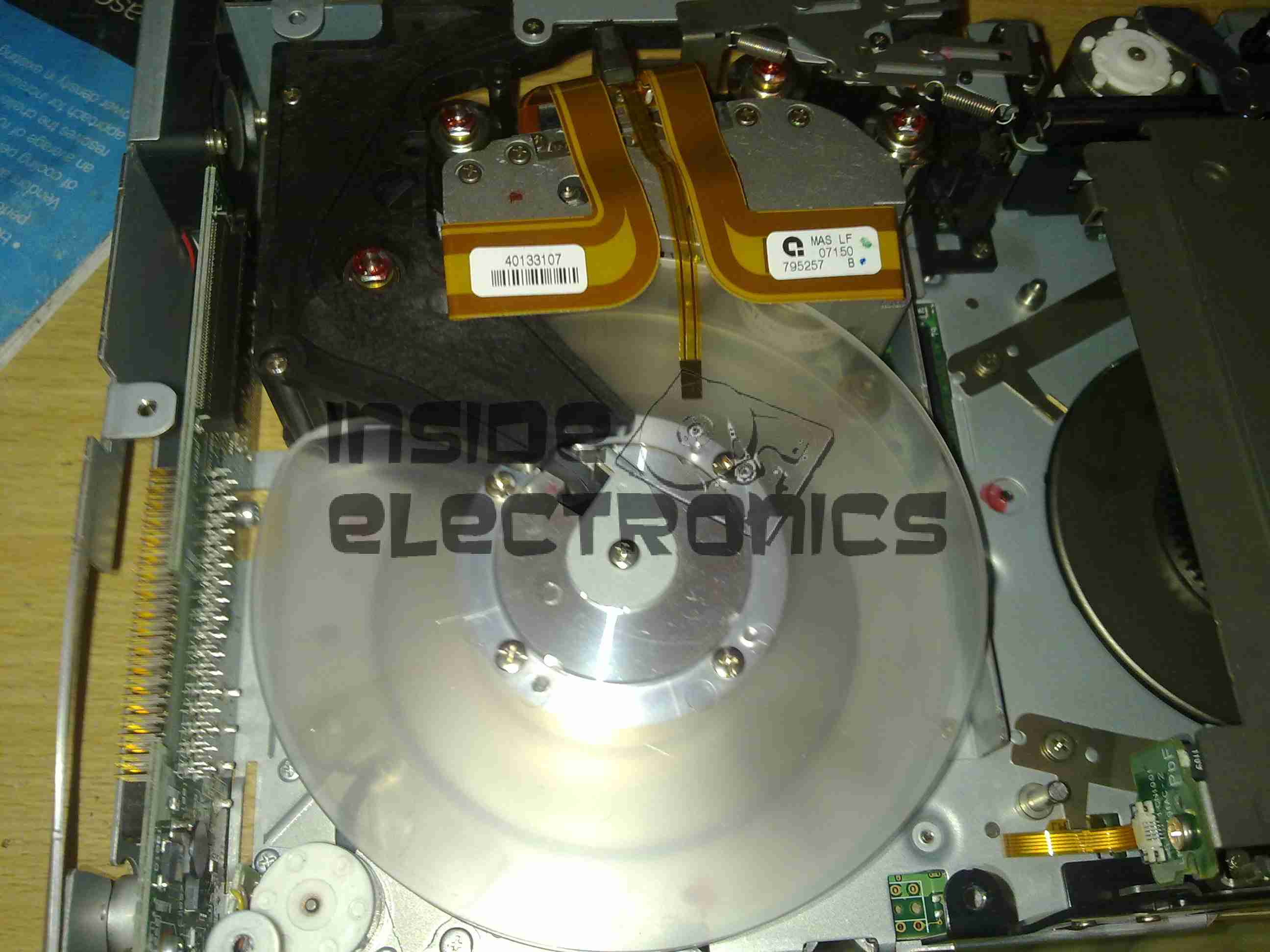
Bottom of the drive with the cover plate removed. Here the spindle drive motors are visible, both brushless 3-Phase units. Both of these motors are driven by a single controller IC on the other side of the lower logic PCB.
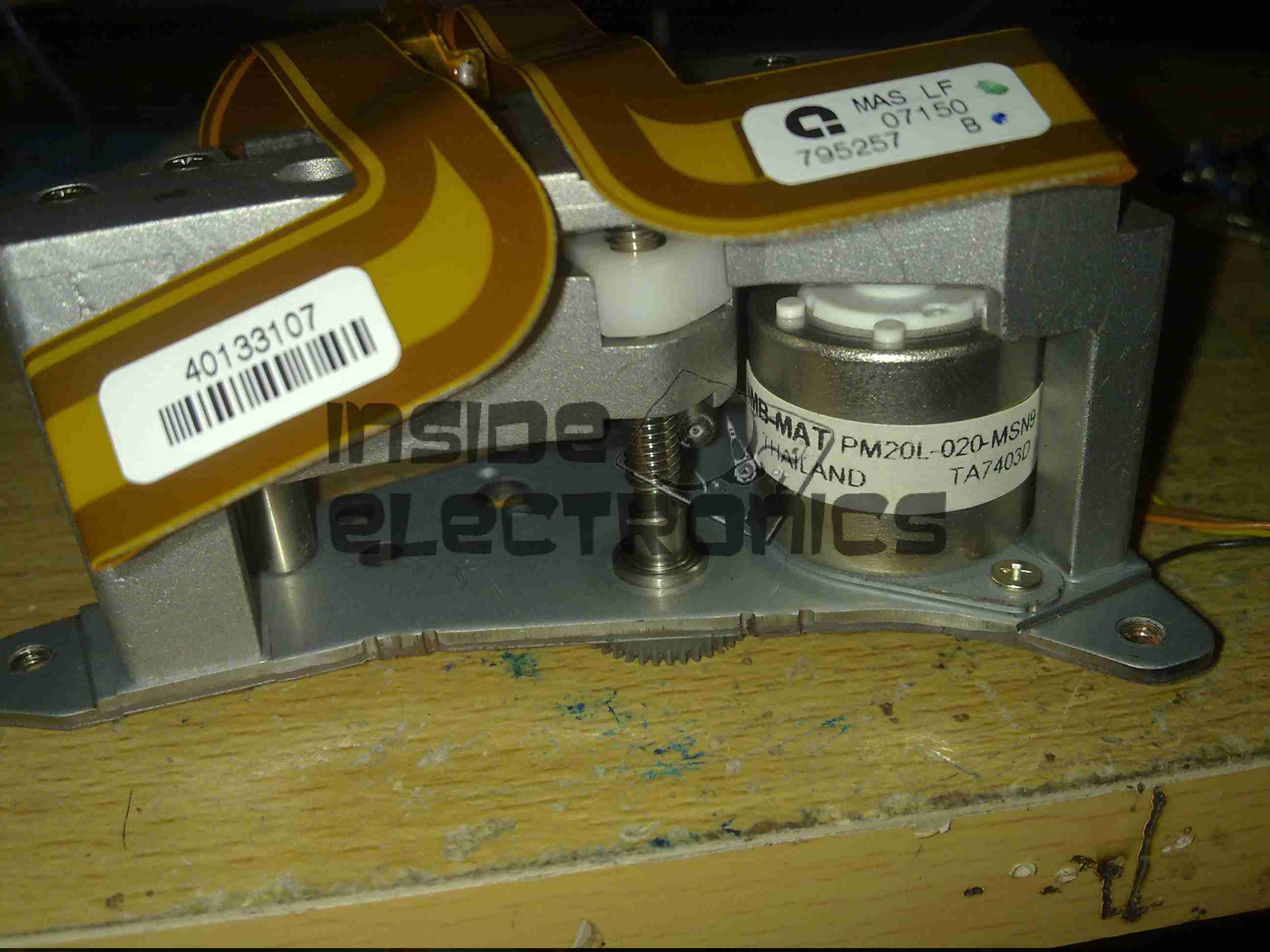
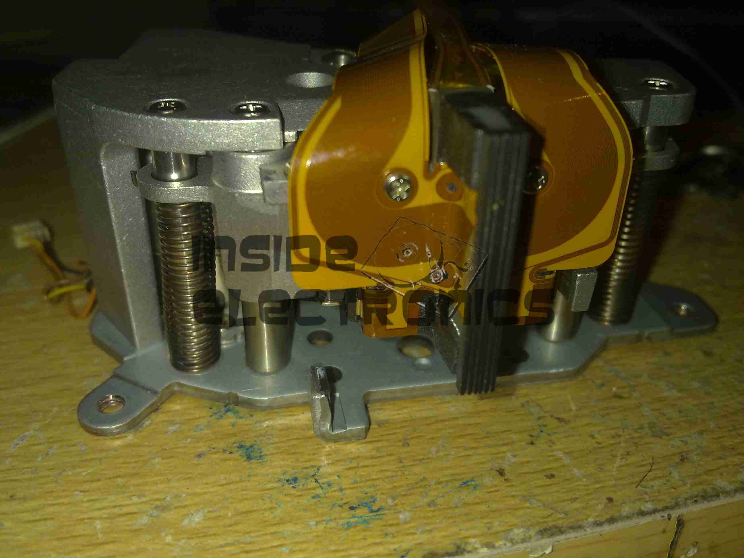
Head Drive Motor
The head is moved up & down the face of the tape by this stepper motor for coarse control, while fine control is provided by a voice coil assembly buried inside the head mount.
Tape Head Assembly
The face of the tape R/W head. This unit contains 2 sets of 8 heads, one of which writes to the tape, the other then reads the written data back right after to verify integrity.
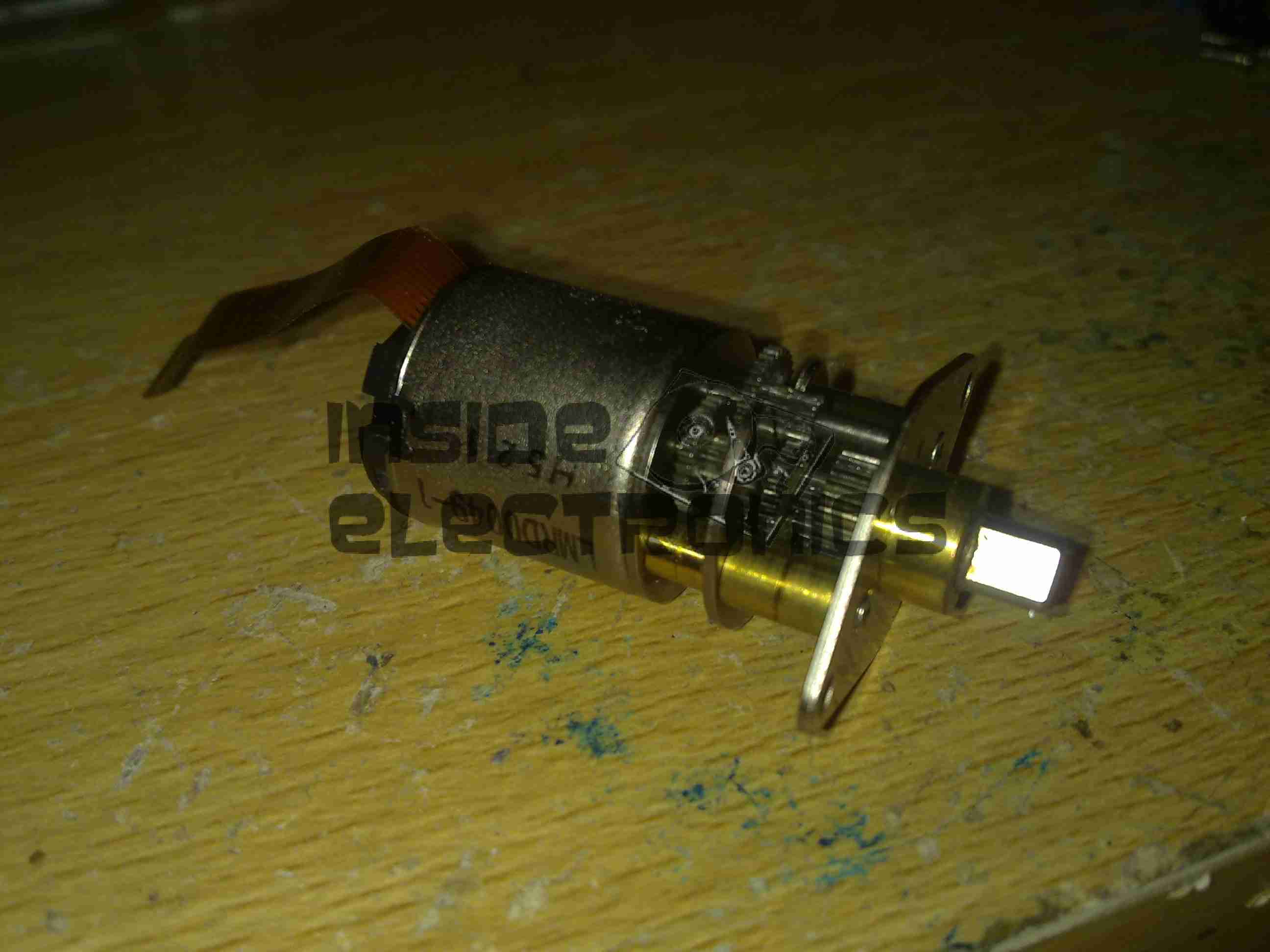
Cartridge Load Motor
The tape cartridge loading motor. I originally thought that this was a standard brushed motor, but it has a ribbon cable emerging, this must be some sort of brushless arrangement.
A replacement drive is on the way, I shall be documenting some more of my archiving efforts & system setup once that unit arrives.
Continuing from my previous post where I published an Eagle design layout for AD7C‘s Arduino powered VFO, here is a completed board.
I have made some alterations to the design since posting, which are reflected in the artwork download in that post, mainly due to Eagle having a slight psychotic episode making me ground one of the display control signals!
AD9850 VFO
The amplifier section is unpopulated & bypassed as I was getting some bad distortion effects from that section, some more work is needed there.
The Arduino Pro Mini is situated under the display, and the 5v rail is provided by the LM7805 on the lower left corner.
Current draw at 12v input is 150mA, for a power of 1.8W total. About 1W of this is dissipated in the LM7805 regulator, so I have also done a layout with an LM2574 Switching Regulator.
The SMPS version should draw a lot let power, as less is being dissipated in the power supply, but this version is more complex.
DDS VFO-SMPS
Here the SMPS circuit can be seen on the left hand side of the board, completely replacing the linear regulator.
I have not yet built this design, so I don’t know what kind of effect this will have on the output signal, versus the linear regulator. I have a feeling that the switching frequency of the LM2574 (52kHz) might produce some interference on the output of the DDS module. However I have designed this section to the standards in the datasheet, so this should be minimal.
Nevertheless this version is included in the Downloads section at the bottom of this post.
The output coupled through a 100nF capacitor is very clean, as can be seen below, outputting a 1kHz signal. Oscilloscope scale is 0.5ms/div & 1V/div.
VFO Output (Mucky ‘Scope)Scope Connected
Thanks again to Rich over at AD7C for the very useful tool design!
Linked below is the Eagle design files for this project, along with my libraries used to create it.
While sourcing the main propulsion hydraulic system for nb Tanya Louise in the summer, we thought that it would be convenient to have an on board generator that didn’t require dragging off the boat & highly explosive petrol to operate.
As the hydraulics were already being fitted, we decided to add a hydraulically driven generator to solve this issue.
And this is where the problems began…
We were referred to Mike Webb of hydraulicgenerators.co.uk to supply the equipment required for this part of the project, this was to include the alternator itself, hydraulic motor to drive the alternator, the required adaptor plates to mate the motor to the generator head & a control valve block to regulate the oil flow & pressure to the motor.
After a phone call to Mike on 16-07-2013 to discuss our requirements, we settled on a system. I received the following E-Mail the next day from Mike:
Good morning, reference our conversation, Martin from BSP has given me details as to what he will be supplying, on that basis and in light of the special price I have offered, this is what I propose to supply,
1 off New 8kVa – 7kW Hydraulic driven generator 220v single phase 50hz c/w flow control valve, pressure relief valve and on/off solenoid valve, Martin did say that the engine idle is between 1000 and 1200 rpm and max speed is 3600 rpm, valves will be rated accordingly. I have the alternator and parts available now, in order for me to be able to offer this at a significantly discounted price of £ 1.200.00 nett, I will need to utilise the components I have in stock now, so I will need payment asap, delivery will be approx. 7 days, primarily due to the fact that the coupling is fabricated to suit, I can either deliver the unit to you when ready or BSP or hold onto it until everything else is in place. The alternator is a Meccalte S20W that I bought for another customer a few weeks ago, but he cancelled and I don’t have, at this time, anyone else interested in it, so either I do a deal with you at the above price or wait until someone else comes along and wants the unit.
With regards to installation, let me know if you need any help, but it would be best to install when the engine is being installed and the rest of the system hosed up, I assume BSP will be sorting this, in which case I’ll liase with Martin.
I trust that this meets with your approval and look forward to hearing from you.
At this point an order was placed with Mike, & the money transferred so he could begin building the unit for us. As can be seen from the E-Mail, a lead time of 7 days was stated.
After a few phone calls over the following month, firstly being told that the custom parts to mate the generator to the motor had not come back from the engineers, I sent another E-Mail to Mike on 10-09-2013, and got no reply.
Following another phone call, I was told that the generator had been shipped, however Mike would not give me any tracking details for the shipment, and would not initially tell me who it was shipped with.
Again the generator didn’t turn up.
More phone calls ensued & I was told at this point that the shipping company had been confused by the address given, shipped back to Mike. At this point I was informed that the shipping company had actually LOST it. Several more phone calls later I was promised that a replacement generator would now ship no later than 08-10-2013. A follow up E-Mail two days later also generated no reply.
At this point I was beginning to wonder if I would ever see the goods we had paid for, but finally a shipment arrived from Mike
~15-10-2013, over TWO MONTHSafter our promised delivery date. However, even having been delivered, all was not well with the goods.
Generator Pallet
Above is the generator supplied. No mounting bracket, no integrated valve block, in short, nothing like what was described in Mike’s documentation & website. The original documentation is available here for reference: [download id=”5564″]
As can be seen, there is an open port on the side of the valve block. This is where the ON/OFF control solenoid valve is supposed to be located.
After several more unanswered E-Mails & phone calls, I had to get somewhat more forceful in my messages, as now Mike had begun outright lying about what was specified in the original order. In which that there was no solenoid valve required. So the following E-Mail was sent 21-10-2013:
Mike,
Having had a conversation with Martin, about him attempting to contact you regarding what you have supplied to us, I need this resolving ASAP now, as I am being held up by the fact that there is an open port on your valve block where the solenoid control valve is supposed to be located.
As it stands the valve block & therefore the generator you have supplied to us is useless for it’s intended purpose & I will be seeking legal advice on this matter if a resolution cannot be made this week, considering you have not replied to any E-Mail I have sent since the unit’s massively delayed arrived.
In your original correspondence it is certainly indicated that this valve was to be fitted, which was also Martin’s instruction to you.
I await your expedient response.
This threat of legal action actually spurred a response from Mike, who finally replied with the following on 25-10-2013:
Ben,
Sorry about all this, I have been away and down with a bug for the last week, I will sort this today and will have the required parts shipped to you on Monday for Tuesday delivery.
Regards
Mike
Another promise of a delivery date, so I waited a little longer, until the Friday of that week. Still no delivery. No surprise there then.
(I didn’t believe the story about illness either).
At this point I again attempted contact, but got nowhere, even with legal threats. So I’ve given up completely on this & been forced to source the parts elsewhere at extra cost.
This company is not the one to go to if you require a hydraulic generator unit for any application, as you’d be lucky to get any part of what you order on time, if at all.
Operations are run by an all out liar who seems to be happy to accept money but not ship the goods that had been paid for.
Mike having explained to me that the shipping company had lost a generator, and he would have to build me another one to replace it also does not make sense, as in the initial phone call & mail he stated that the Meccalte generator that we eventually received was a single unit that was specially ordered for another client, and the factory build date on the unit certainly gave away the fact that the generator head had been sat around for some considerable time before I came along & made a purchase.
Hopefully this post will get a high Google ranking, to ensure that anyone else who happens to be looking for a similar piece of equipment does not have the misfortune to trust this man.
We were referred to him on good faith & unfortunately in this case it did not go well.
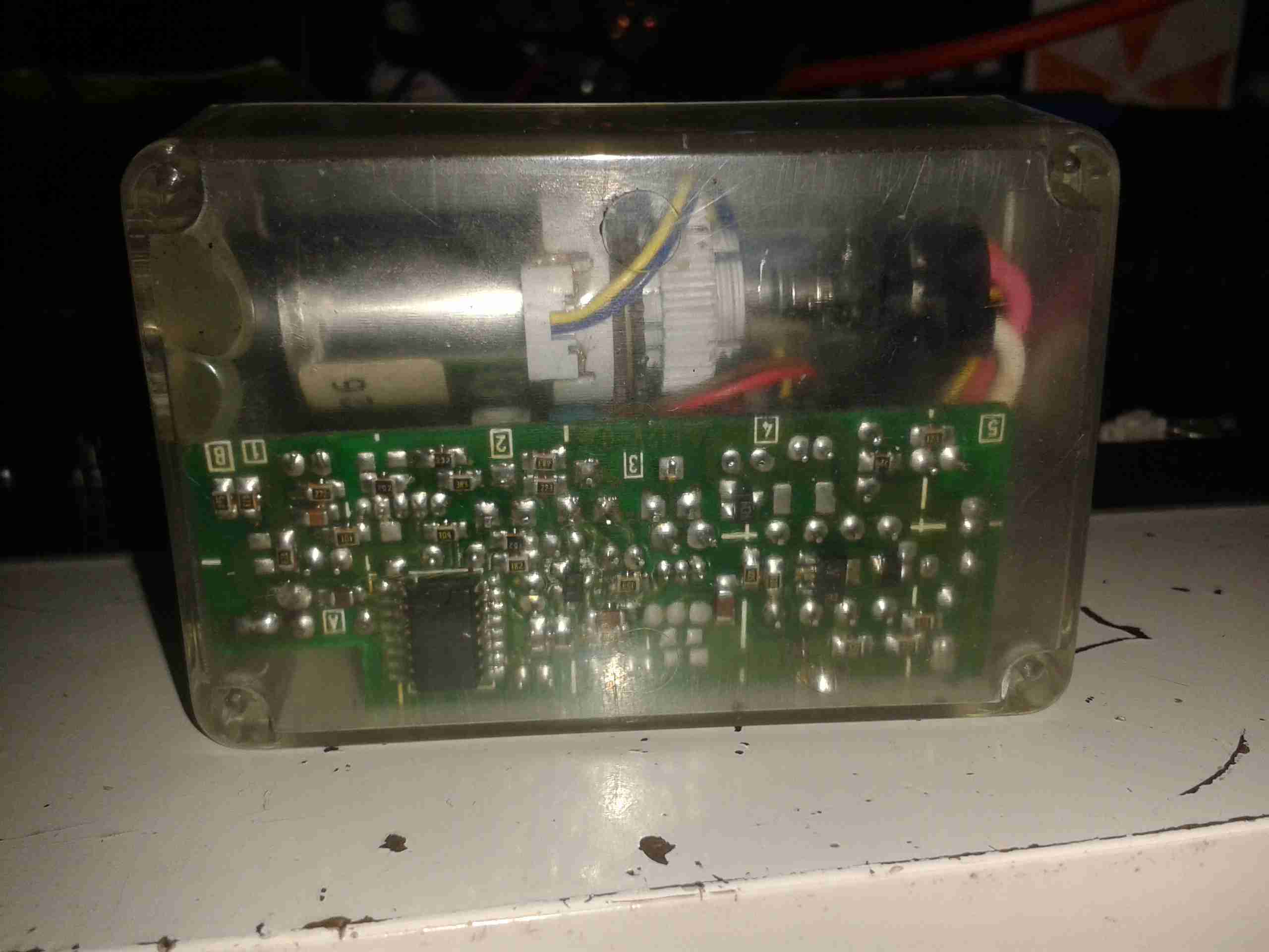
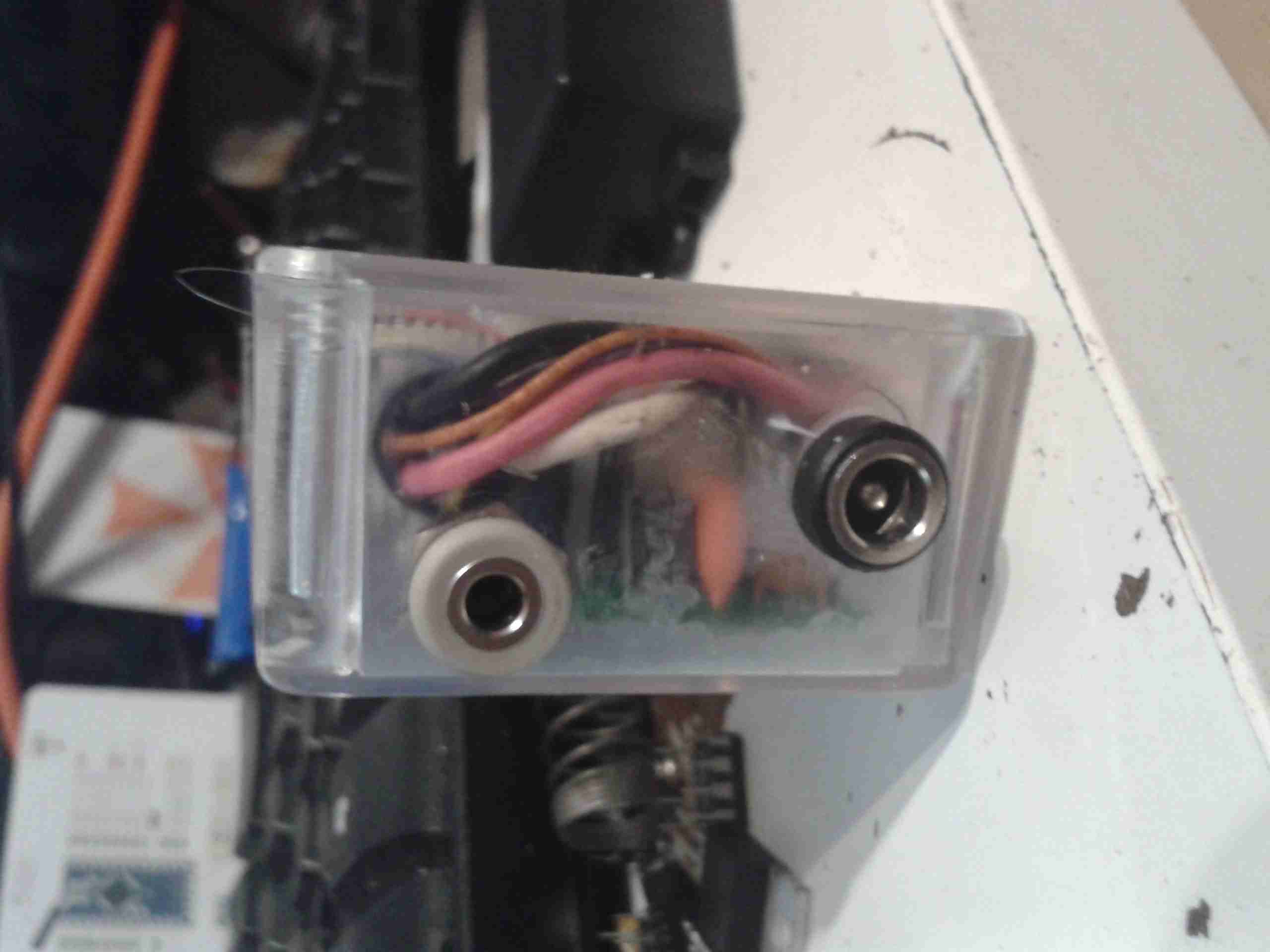
This is the control unit for a Routemaster system, that downloads traffic information for the area local to the vehicle.
Unit Overview
Here is an overview of the unit, in it’s aluminium box.
Here is the unit with the top cover removed, showing the pair of PCBs. The bottom PCB is the main control PCB, the top one holds an IC similar to a SIM card & part of the radio.
Cover Removed
Main PCB Top
Here is the main PCB removed from the casing, contains the program ROM & microcontroller. for the system
Daughtercard view. This holds another programmed CPLD, the custom SIM-like IC & the RTC battery, along with some power conversion circuitry.
Daughterboard Top
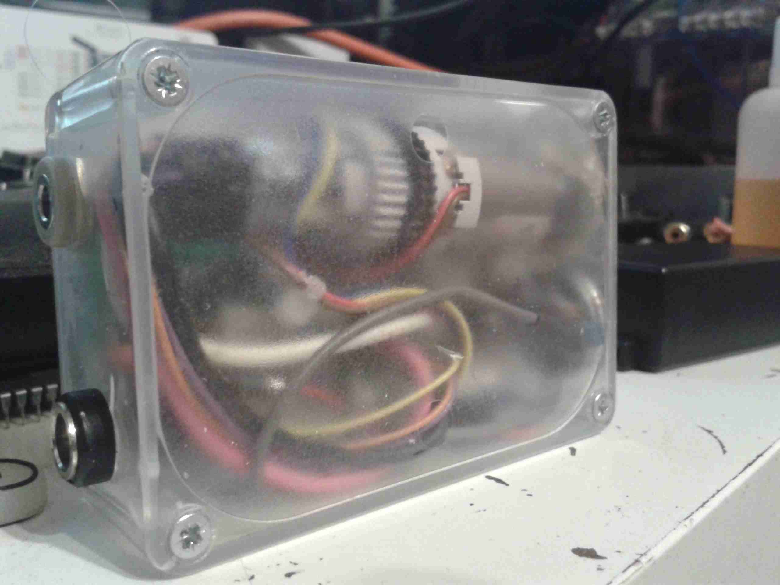
Radio Receiver
This is the radio receiver, looks to be AM, the large loop antenna can be seen at the bottom of the box.
Tip Jar
If you’ve found my content useful, please consider leaving a donation by clicking the Tip Jar below!
All collected funds go towards new content & the costs of keeping the server online.