Posted on 10 Comments

Sony HVC-3000P Trinicon Camera Teardown

Camera Left
Camera Left

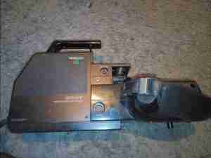
Following on from the viewfinder teardown, here’s the rest of the camera. This unit dates back to 1980, and is made almost exclusively of cast aluminium. Very little plastic has been used here & only for the bits that the user comes into contact with. This camera is based around the Sony Trinicon camera tube system, technology dating back before CCDs. There aren’t many controls on this side of the camera, only the record button, which is hidden behind the camera handgrip.
Camera Right
Camera Right

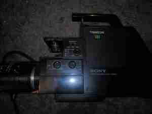
The other side of the camera has most of the controls for the picture.
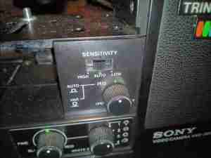
Image Controls
Image Controls

The image controls inclue auto / manual iris, white balance & colour balance.
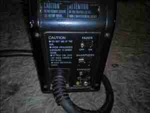
Rear Panel
Rear Panel

Sharpness & fader controls are on the back of the camera, along with the umbilical cable which would have connected to a Betamax recorder.
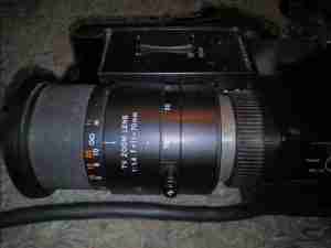
Main Lens
Main Lens

The lens on this camera is massive, at least a kilo of optical glass. Focus control is manual, with both auto & manual zoom control.
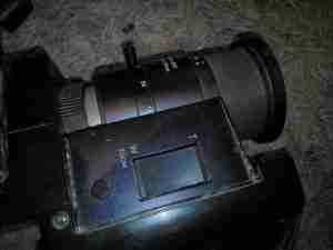
Lens Zoom Control
Lens Zoom Control

The Zoom controls are on top of the grip, with a button to the rear of the control which I have no idea about. The internal belts are a bit rotted with age so the zoom function doesn’t work great.
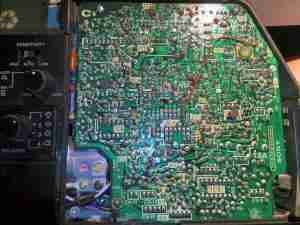
Trinicon Control Board

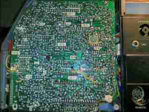
After removing the side covers, the two large PCBs become visible. These units are absolutely packed with electronics. On this side is the Trinicon tube control board, generating all the high voltages for electron beam acceleration, focus & electrostatic deflection of the beam. There’s around 500 volts knocking around on this board, with some rather specialised hybrid modules doing all the high voltage magic.
Video Process Board
Video Process Board

The other side of the camera has the video process board, which performs all the colour separation of the video signal from the tube, processes the resulting signals into a composite video signal, and finally sends it down the umbilical.
Bare Controls
Bare Controls

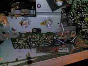
Removing some of the remaining covers exposes the bare video controls, and a small PCB just underneath covered in trimpots to set factory levels.
White Balance Filter Arm

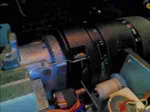
The white balance is partially electronic & partially mechanical. This lever actuates a filter inside the lens assrembly.
Remote Connector
Remote Connector

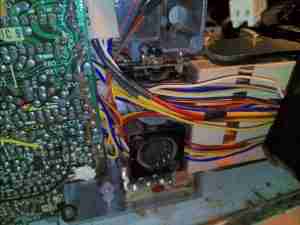
A DIN connector offers remote control ability. The large loom of wires disappearing off to the right is dealing with the zoom mechanism & the onboard microphone amplifier. Just under the DIN connector hides the system power supply, inside a soldered can. The can under the white tape is the head end amplifier for the Trinicon video tube.
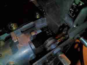
Trinicon Mount
Trinicon Mount

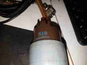
Hiding in the centre of the camera inside the casting is the Trinicon tube assembly itself. The label can just be seen here.
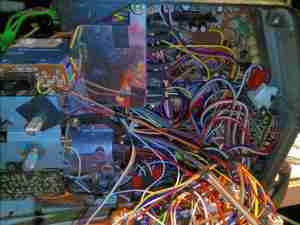
Camera Internals 1
Camera Internals 1

As is typical of 1980’s electronic design, the main boards swing down & are designed to slot into the base casting folded out for repairs. Internally the unit is a rat’s nest of wiring loom. There’s also another shielding can in here nestled between the boards – this is the video sync generator circuit.
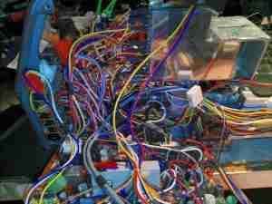
Camera Internals 2
Camera Internals 2

The other side gives a better view of the video sync generator can. I’ll dive into the individual modules later on.
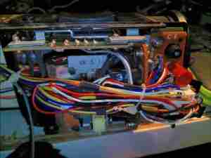
Lens Zoom Assembly
Lens Zoom Assembly

Under the remaining side cover is the zoom assembly & microphone amplifier board. More massive wiring loom hides within.
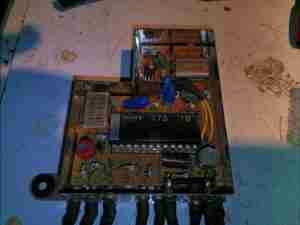
Video Sync Generator

The video sync generator is pretty sparse inside, just a large Sony CX773 Sync Generator IC, with a pair of crystals. There are a couple of adjustments in here for video sync frequencies.
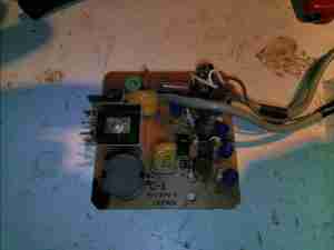
Head End Amplifier
Head End Amplifier

Removed from it’s shielding can, here is the head end amplifier for the Trinicon tube. This very sensitive JFET input amplifier feeds into the main video process board.
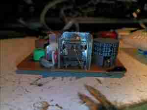
Input Transformer
Input Transformer

The Trinicon tube target connects to this input transformer on the front of the amplifier board.
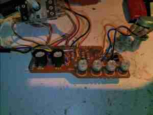
Internal Video Adjustments

The internal white balance controls are on this small PCB, mounted under the user-accessible controls.
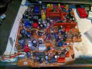
Vidicon Control Board

Here’s the main control board responsible for the Trinicon tube & exposure control. Down near the front is the auto-iris circuit, nearer the centre is timing control & at the top is the high voltage power supply & deflection generator ICs.
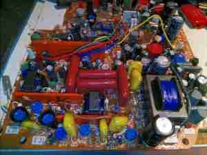
High Voltage Section

Here’s the high voltage section, the main transformer at right generating the voltages required to drive the video tube. The large orange hybrids here are a pair of BX369 high-voltage sawtooth generators that create the deflection waveforms for the tube. The other large hybrid is a BX382 Fader Control.
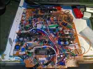
Video Process Board
Video Process Board

The other large board contains all the video process circuitry, all analogue of course. There are a lot of manual adjustment pots on this board.
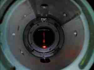
Lens Barrel
Lens Barrel

After removing the lens assembly, the tube assembly is visible inside the barrel casting. Not much to see yet, just the IR filter assembly.
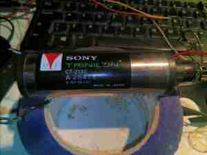
Trinicon Tube Assembly

Here’s the unit removed from the camera. Unfortunately this tube is dead – it shows a lot of target burn on the resulting image, and very bad ghosting on what poor image there is. The Trinicon tube itself is encased in the focus coil assembly, the windings of which are hidden under the shielding.
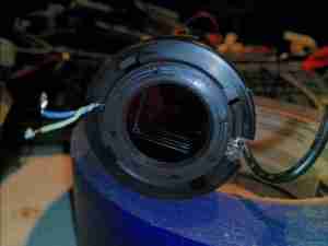
IR Filter
IR Filter

The IR filter is locked into the front of the tube, on a bayonet fitting. The twin target wires are running off to the left, where they would connect to the head end amplifier.
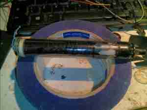
Bare Tube
Bare Tube

After removing the IR filter glass, the Trinicon tube itself is removed from the focus coil assembly. There’s an electron gun at the rear of the tube, like all CRTs, although this one works in reverse – sensing an image projected on the front instead of generating one.
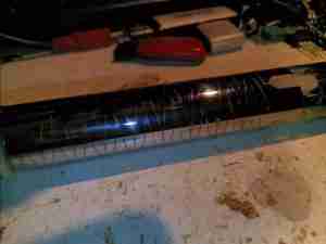
Deflection Plates
Deflection Plates

It’s a little difficult to see, but the electrostatic deflection electrodes in this tube are created from the aluminium flashing on the inside of the glass, in a zig-zag pattern. The interleaving electrodes are connected to base pins by spring contacts at the electron gun end of the tube.
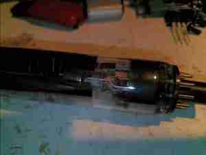
Electron Gun
Electron Gun

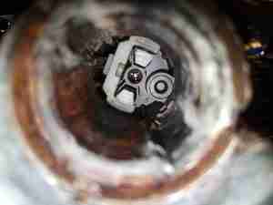
The electron gun is mostly hidden by the getter flash & the deflection electrodes, but the cathode can is visible through the glass, along with the spring contacts that make a connection to the deflection electrodes. This is also a very short gun – it doesn’t extend more than about 5mm into the deflection zone. The rest of the tube up to the target is empty space.
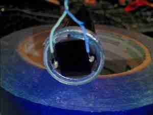
Target
Target

Finally, here’s the target end of the tube. I’m not sure how the wires are attached to the terminals – it certainly isn’t solder, maybe conductive adhesive?
It uses a vertically striped RGB colour filter over the faceplate of an otherwise standard Vidicon imaging tube to segment the scan into corresponding red, green and blue segments. It is used mostly in low-end consumer cameras, though Sony also used it in some moderate cost professional cameras in the 1980s.
Although the idea of using colour stripe filters over the target was not new, the Trinicon was the only tube to use the primary RGB colours. This necessitated an additional electrode buried in the target to detect where the scanning electron beam was relative to the stripe filter. Previous colour stripe systems had used colours where the colour circuitry was able to separate the colours purely from the relative amplitudes of the signals. As a result, the Trinicon featured a larger dynamic range of operation.

I have the service manuals below for the HVP-2000P & the HVP-4000P, which are very similar cameras, so these may be useful to anyone who has one of these!
Posted on Leave a comment

Turbine Fuel Pump Extreme Teardown

Turbine Fuel Pump
Turbine Fuel Pump

Here’s a destructive teardown of an automotive in-tank turbine fuel pump, used on modern Petrol cars. These units sit in the tank fully immersed in the fuel, which also circulates through the motor inside for cooling. These pumps aren’t serviceable – they’re crimped shut on both ends. Luckily the steel shell is thin, so attacking the crimp joint with a pair of mole grips & a screwdriver allowed me inside.

End Bell
End Bell

The input endbell of the pump has the fuel inlet ports, the channels are visible machined into the casting. There’s a pair of channels for two pump outputs – the main fuel rail to the engine, and an auxiliary fuel output to power a venturi pump. The fuel pump unit sits inside a swirl pot, which holds about a pint of fuel. These are used to ensure the pump doesn’t run dry & starve the engine when the tank level is low & the car is being driven hard. The venturi pump draws fuel from the main tank into the swirl pot. A steel ball is pressed in to the end bell to provide a thrust bearing for the motor armature.

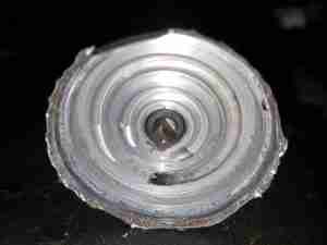
Turbine Impeller
Turbine Impeller

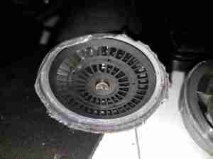
The core of the pump is this impeller, which is similar to a side-channel blower. From what I’ve been able to find these units supply pressures up to about 70PSI for the injector rail. The outside ring is the main fuel pump, while the smaller inner one provides the pressure to run the venturi pump.

Pump Housing
Pump Housing

The other side of the machined pump housing has the main output channel, with the fuel outlet port at the bottom. The motor shaft is supported in what looks like a carbon bearing.

Midsection
Midsection

Removing the pump intermediate section with the bearing reveals quite a bit of fungus – it’s probably been happy sat in here digesting what remains of the fuel.

Armature Exposed
Armature Exposed

Some peeling with mole grips allows the motor to come apart entirely. The drive end of the armature is visible here.

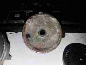
Motor Can
Motor Can

The outer shell of the motor holds yet more fungus, along with some rust & the pair of ceramic permanent magnets.

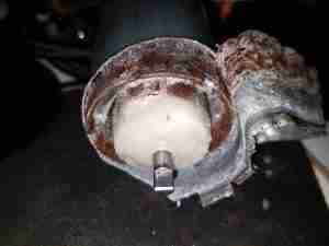
Brushes
Brushes

The other end of the pump has the brush assembly, and the fuel outlet check valve to the right. The bearing at this end is just the plastic end cap, since there are much lower forces at this end of the motor. The fuel itself provides the lubrication required.

Potted Armature
Potted Armature

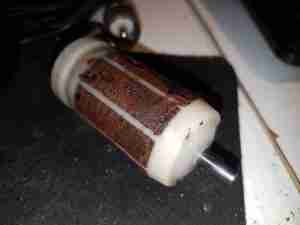
With the armature pulled out of the housing, it’s clear that there’s been quite a bit of water in here as well, with the laminations rusting away. This armature is fully potted in plastic, with none of the copper windings visible.

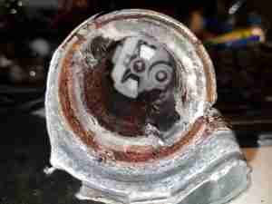
Carbon Commutator
Carbon Commutator

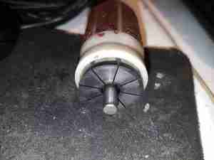
The commutator in these motors is definitely a strange one – it’s axial rather than radial in construction, and the segments are made of carbon like the brushes. No doubt this is to stop the sparking that usually occurs with brushed motors – preventing ignition of fuel vapour in the pump when air manages to get in as well, such as in an empty tank.

Posted on Leave a comment

eBay Airbrush & Compressor

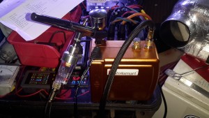
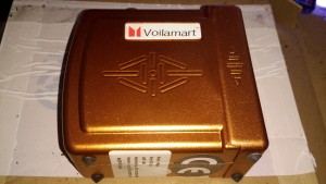
For my latest project, I needed an easier way to paint without messing about with brushes, and the associated marks they leave in a paint job. eBay provided me with a cheap airbrush & compressor.

Airbrush Kit
Airbrush Kit

For less than £30, this kit doens’t look so bad. I’ve never used an airbrush before, but I’ve had no problems with this as yet spraying both water based paints & solvent based paints.

Compressor
Compressor

Here’s the compressor itself, this runs on 12v & has an output pressure of 1.5 Bar, which is supposed to be adjustable.

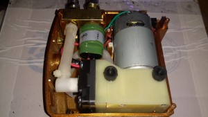
Compressor Internals

Removing a couple of screws reveals the internal components. Nothing much unusual here, a DC diaphragm pump, pressure switch & outlet fittings. There’s also a thermal cutout fitted next to the motor for protection.
The pressure switch attached to the manifold trips at 1.5Bar, keeping the pressure to the brush pretty much constant.

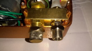
Air Block
Air Block

Next to the air outlet fitting is an adjustment knob, supposedly for varying the pressure. However it’s just a piss-poorly designed adjustable relief valve that vents to atmosphere. There’s not much of a control range.

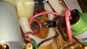
Messy Wiring
Messy Wiring

The wiring gets a bit messy where the power LED is concerned, with no heatshrink over the solder joints, but it’s adequate.

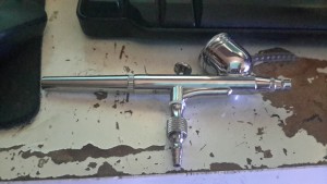
Airbrush
Airbrush

The airbrush itself isn’t too bad. It’s solid Brass, with a very nice Chrome finish. I’m not expecting miracles from a very cheap tool, but it certainly seems to be reasonable.

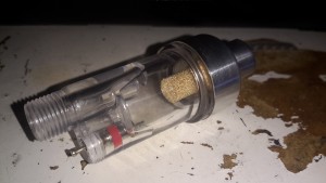
Water Trap
Water Trap

A moisture trap is supplied for the brush, to prevent water drops being sprayed out with the paint. Very handy.

Posted on Leave a comment

Camping Gear – Optimus Nova Multifuel Stove

Stove
Stove

For as long as I can remember I’ve been using Trangia-type alcohol fuelled stoves when I go camping, even though these have served my needs well they’re very limited & tend to waste fuel. I did some looking around for Paraffin/Kerosene fuelled stoves instead, as I already have this fuel on site.
I found very good reviews on the Optimus Nova above, so I decided to go for this one.

This stove can run on many different fuel types, “white gas” (petrol without any vehicle additives) Diesel, Kerosene & Jet A.

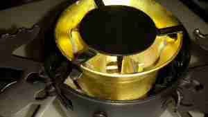
Burner
Burner

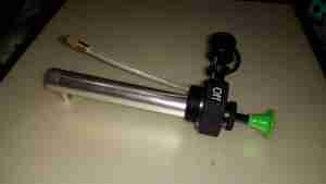
Here’s the “hot end” of the device, the burner itself. This is made in two cast Brass sections, that are brazed together. The fuel jet can be just seen in the centre of the casting.

Fuel Pump
Fuel Pump

The fuel bottle is pressurised with a pump very similar to the ones used on Paraffin pressure lamps, so I’m used to this kind of setup. The fuel dip tube has a filter on the end to stop any munge gumming up the valves or the burner jet.

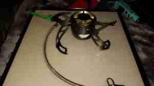
Pre-Heating
Pre-Heating

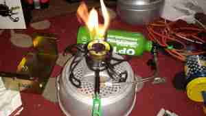
As with all liquid-fuelled vapour burners, it has to be preheated. There’s a fibreglass pad in the bottom of the burner for this, and can be soaked with any fuel of choice. The manual states to preheat with the fuel in the bottle, but as I’m using Paraffin, this would be very smoky indeed, so here it’s being preheated with a bit of Isopropanol.
The fuel bottle can be seen in the background as well, connected to the burner with a flexible hose. The main burner control valve is attached to the green handle bottom centre.

Simmer
Simmer

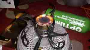
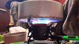
Once the preheating flame has burned down, the fuel valve can be opened, here’s the stove burning Paraffin on very low simmer. (An advantage over the older alcohol burners I’m used to – adjustable heat!)

Full Power!
Full Power!

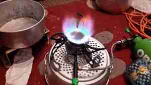
Opening the control valve a couple of turns gives flamethrower mode. At full power, the burner is a little loud, but no louder than my usual Paraffin pressure lamps.

Flame Pattern
Flame Pattern

With a pan of water on the stove, the flame covers the entire base of the pan. Good for heat transfer. This stove was able to boil 1L of water from cold in 5 minutes. A little longer than the manual states, but that’s still much quicker than I’m used to!

Fuel Jet
Fuel Jet

The top of the burner opens for cleaning, here’s a look at the jet in the centre of the burner. The preheating pad can be seen below the brass casting.

Posted on Leave a comment

nb Tanya Louise – Compressor Install

Compressed air is a rather useful power source, especially when all maintenance is done by the on board crew instead of by boatyards.

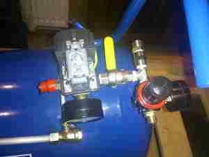
Screwfix had a good deal on a 50L 3.5CFM air compressor, to save space this has been permanently mounted in a free space & air will be piped to where it is needed from a central point.

Because of the total height of the machine, the compressor itself has been unbolted from the tank, a copper line connecting the two back together at a larger distance.

Bearers
Bearers

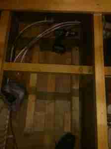
In one of the very few free spaces available, under a bunk. A pair of timbers has been screwed to the floor to support the tank.

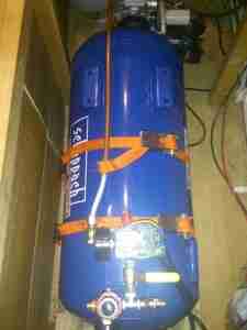
Tank Installed
Tank Installed

The tank is strapped to the wooden supports with a pair of ratchet straps, the compressor itself can be seen just behind the tank. The copper line on the top of the tank is going back to be connected to the compressor outlet.

Air Fittings
Air Fittings

Compressor control remains on top of the tank, the pressure switch & relief valve centre. After an isolation valve, the feed splits, the regulator installed will be feeding the air horn with 20PSI, replacing the existing automotive-style 12v air pump. The currently open fitting will be routed to a quick connect on the bulkhead. This will be accessible from the front deck, an air hose can be fitted to get a supply anywhere on board.

More to come when the rest of the system gets installed!

73s for now.

Posted on Leave a comment

DIY Valve Amplifier – Part 1 – Amplifier Section

Components
Components

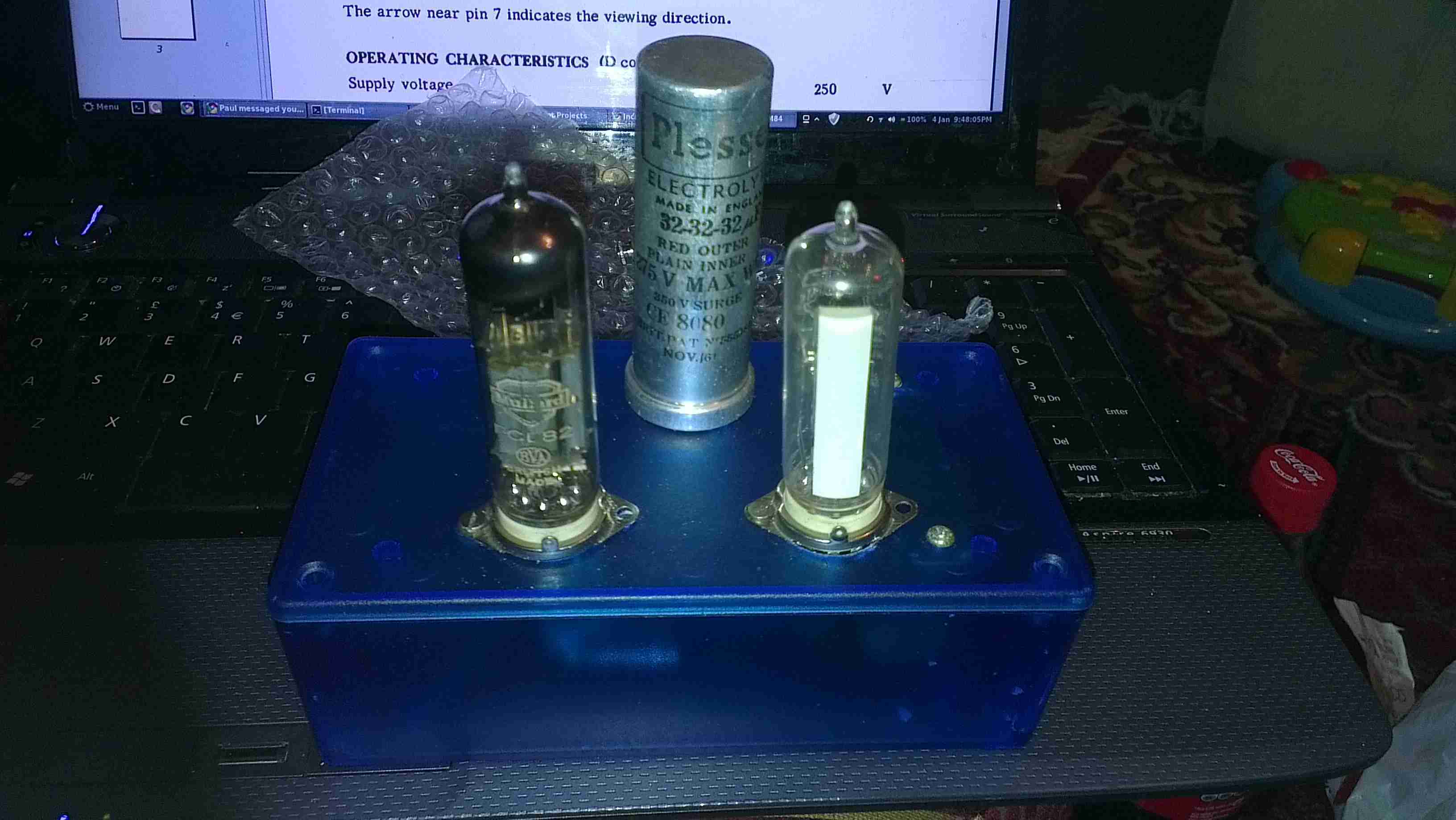
Here are a few details of a valve amplifier I am building, using the valve related parts from a 1960’s reel to reel tape recorder.

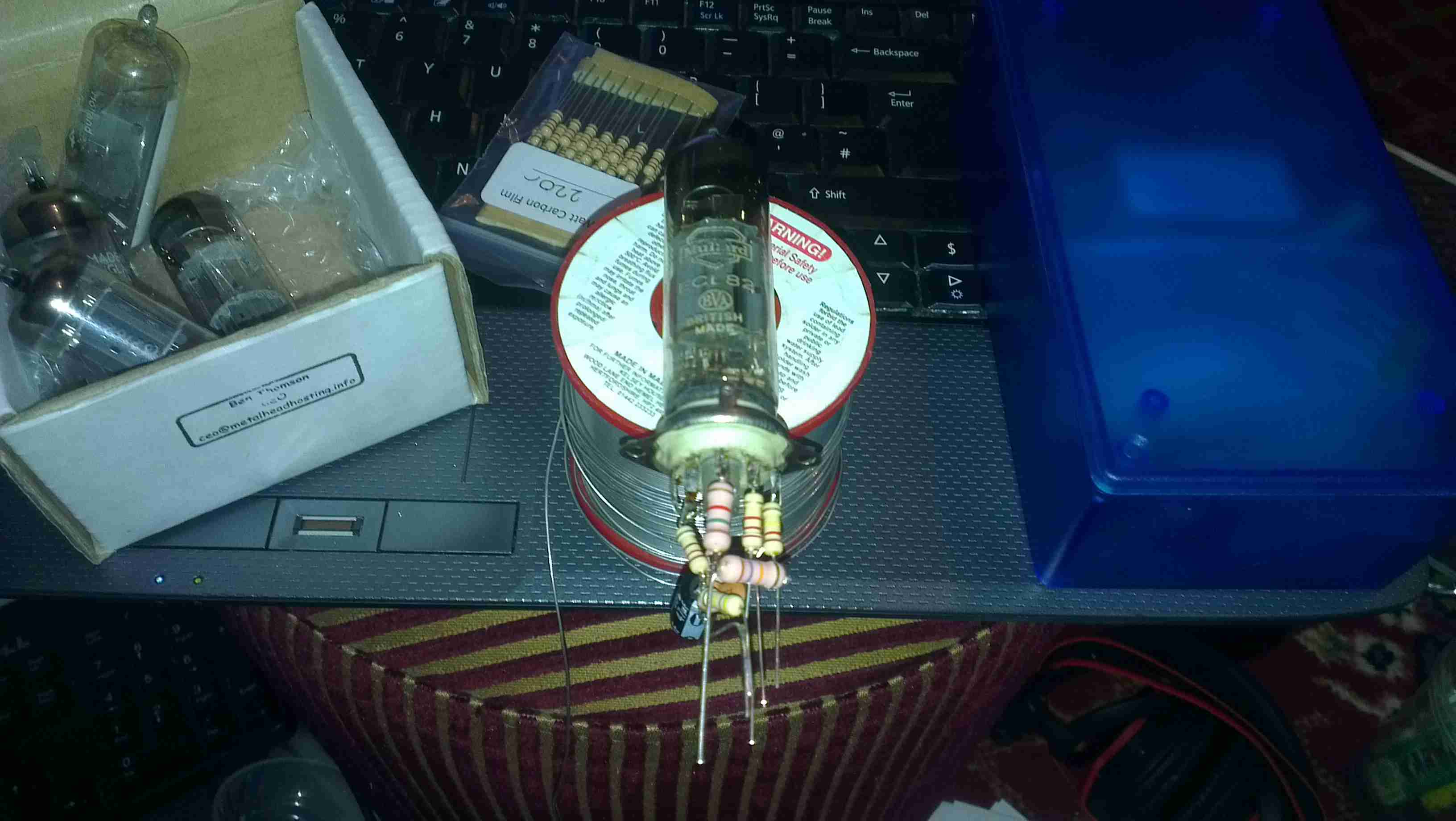
This amplifier is based on an a Mullard ECL82 triode/pentode valve, with an EM84 magic eye tube for level indication.

Beginnings Of The Amplifier

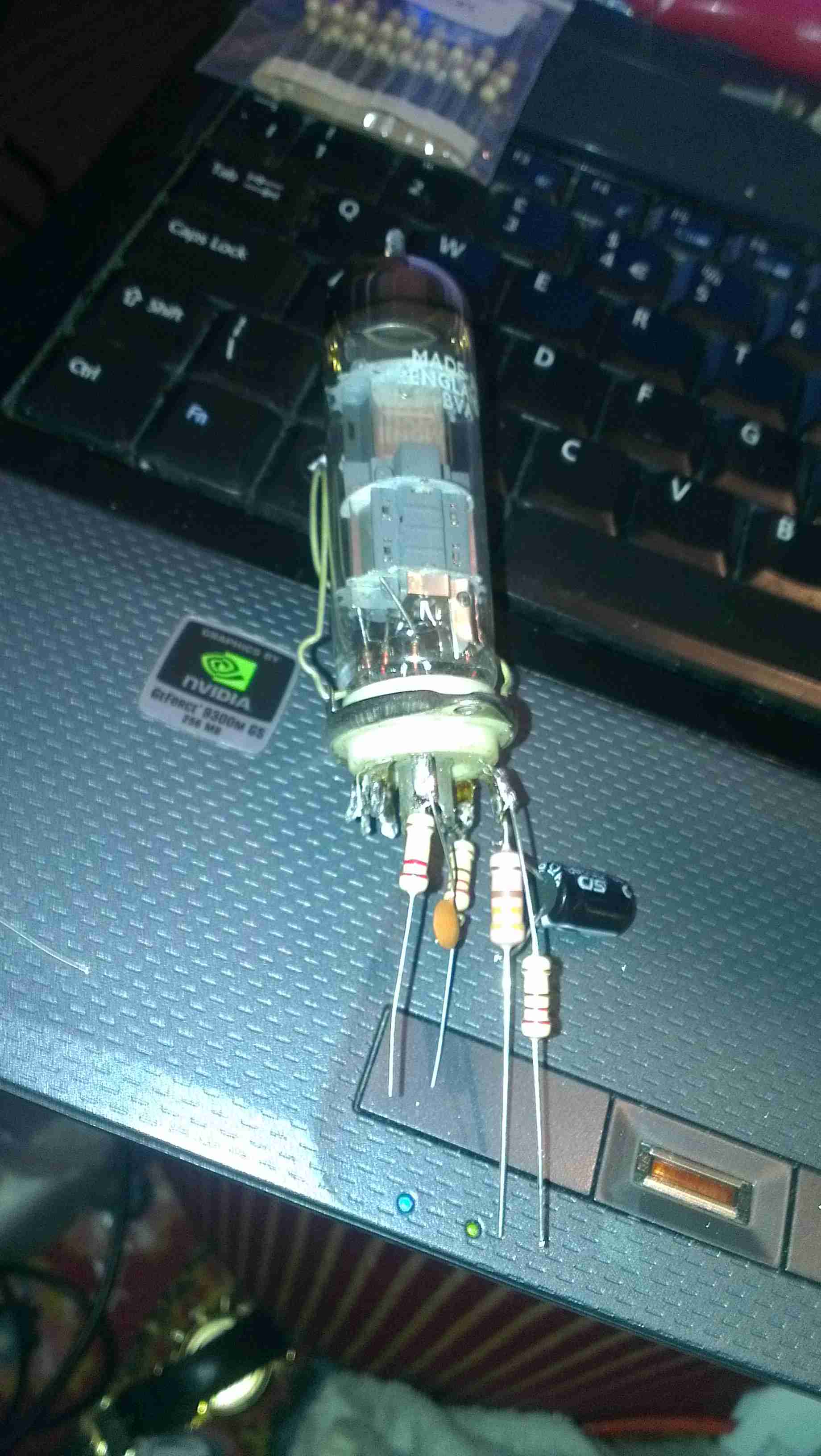
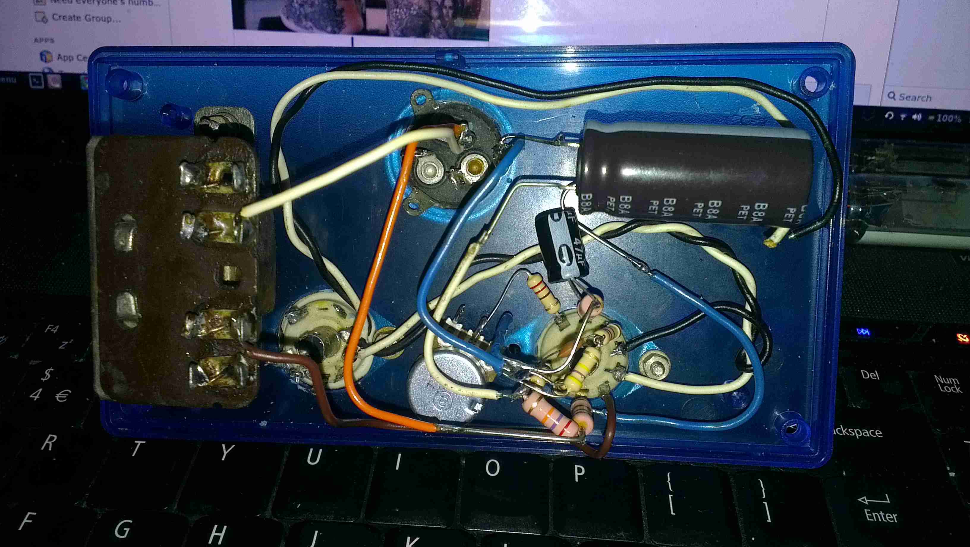
Here the first components are being soldered to the tags on the valve holder, there are so few components that a PCB is not required, everything can be rats-nested onto the valve holders.

Progress
Progress

Progressing with the amplifier section componentry, all resistors are either 1/2W or 2W.

Valve Sockets Fitted

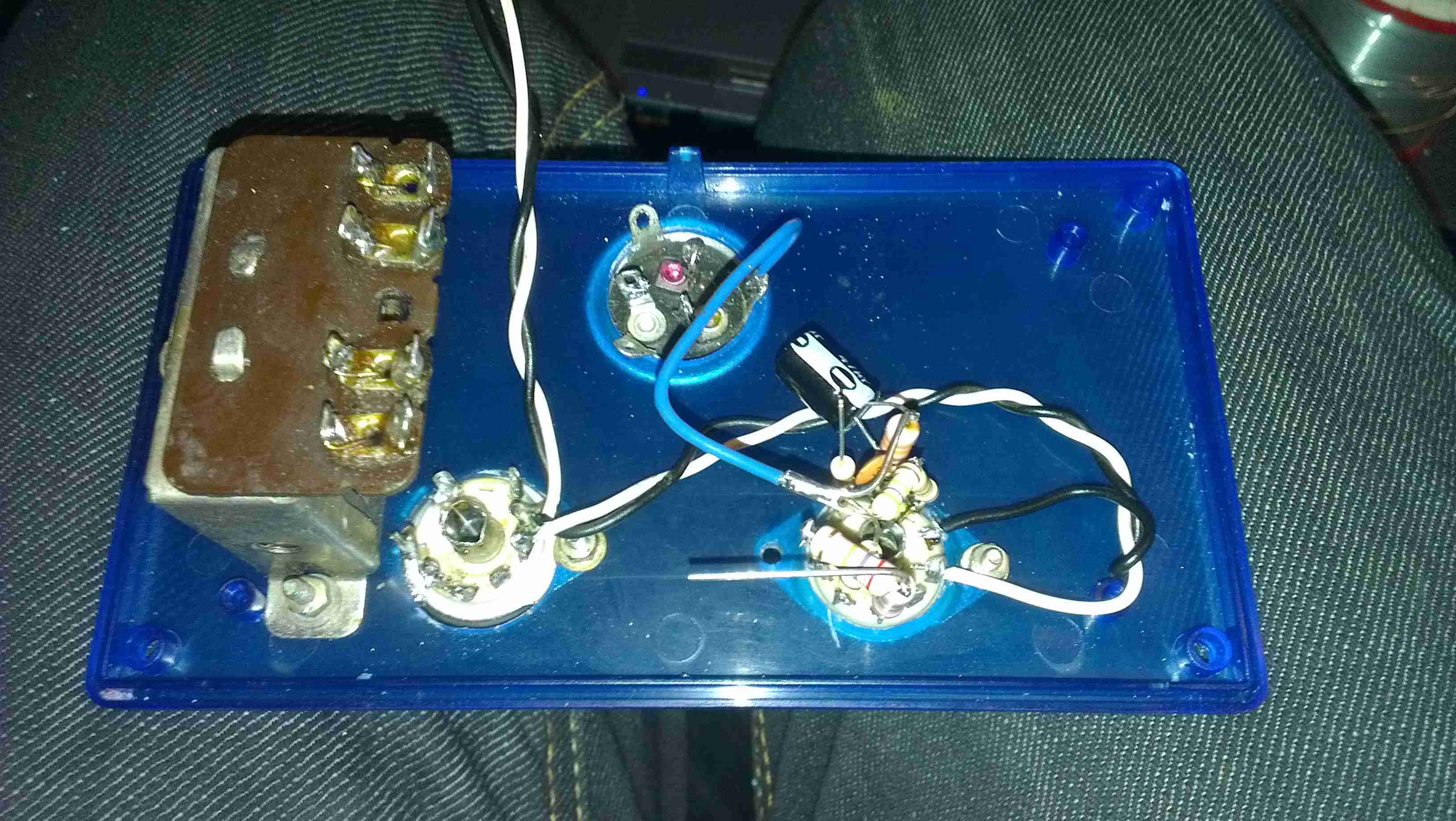
Here the valve holders have been fitted, along with the output transformer, DC smoothing capacitor & the filament wiring, into the top of the plastic housing. At this point all the components that complete the amplifier section are soldered to the bottom of the right hand valve holder.

Wiring
Wiring

Starting the wiring between the valves & the power supply components. The volume control pot is fitted between the valve holders.

Valves Test Fit
Valves Test Fit

The valves here are test fitted into their sockets, the aluminium can at the back is a triple 32uF 250v electrolytic capacitor for smoothing the B+ rail.

Amplifier Section First Test

First test of the amplifier, with the speaker from the 1960’s tape recorder from which the valves came from. the 200v DC B+ supply & the 6.3v AC filament supply is derived from the mains transformer in the background.

Magic Eye Tube Added

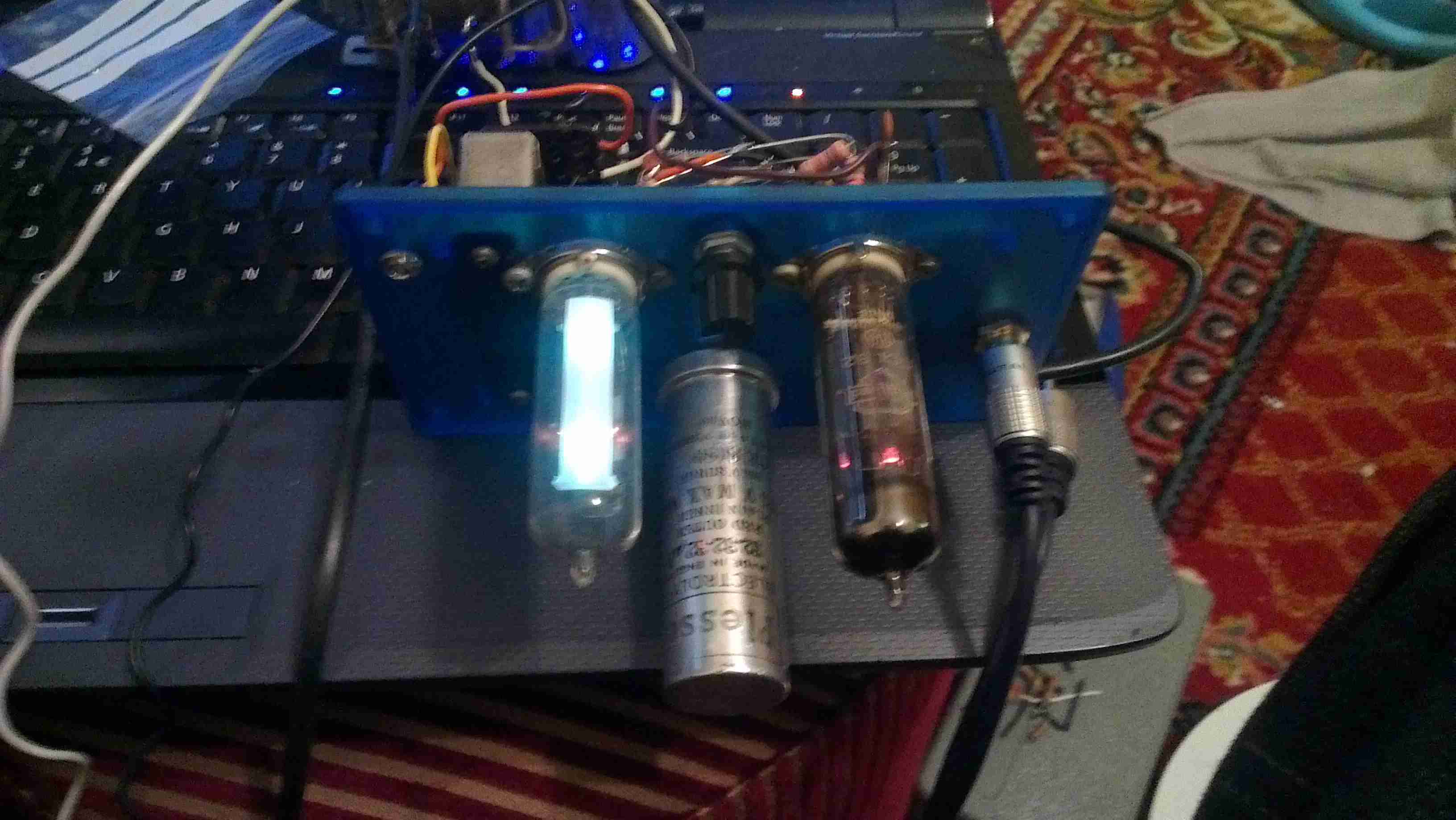
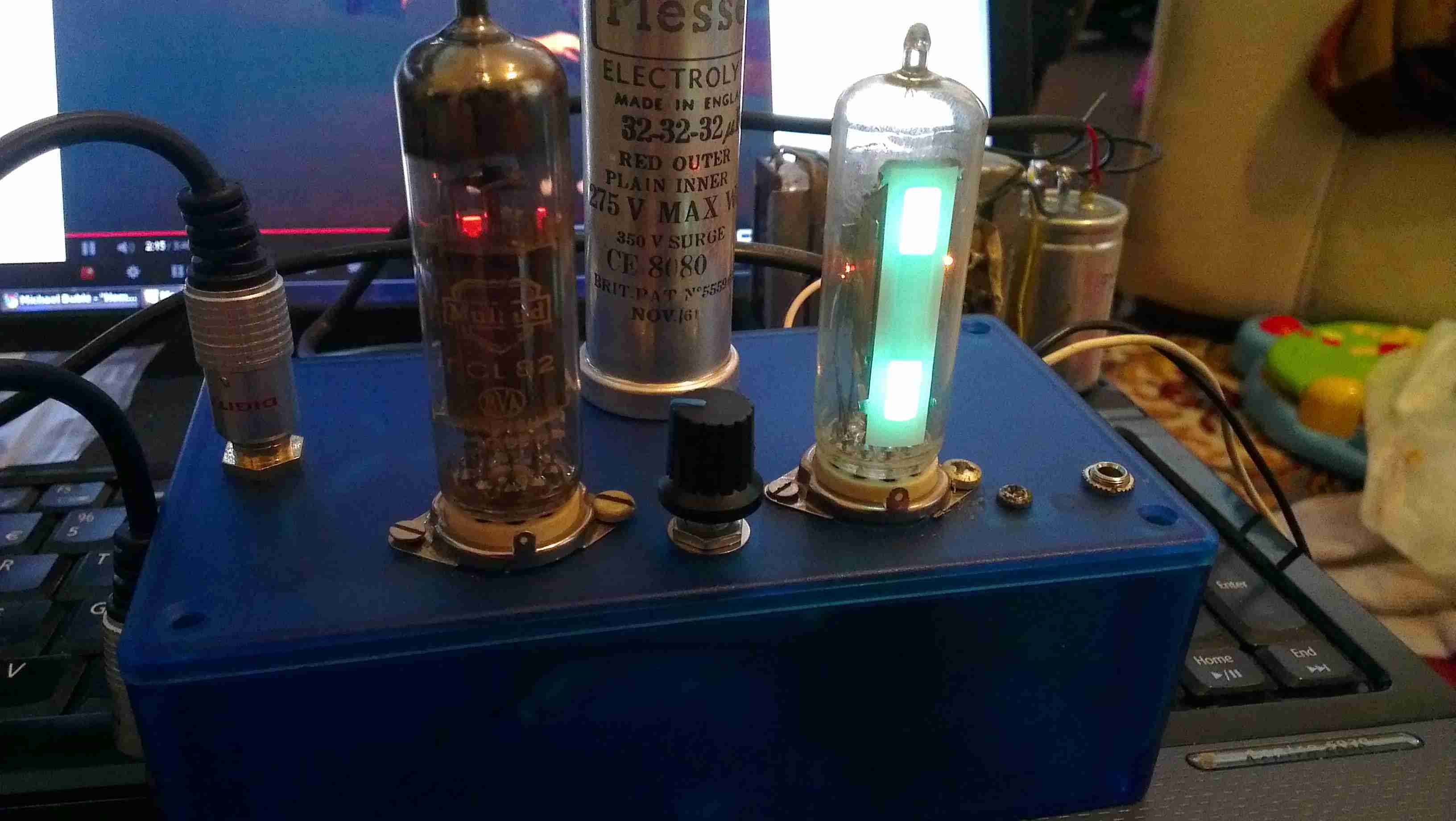
Here the magic eye tube has been fitted & is getting it’s initial tuning to the amplifier section. This requires selecting combinations of anode & grid resistors to set the gap between the bars while at no signal & picking a coupling RC network to give the desired response curve.

Final Test
Final Test

Here both valves are fitted & the unit is sitting on it’s case for final audio testing. the cathodes of the ECL82 can be clearly seen glowing dull red here.


In the final section, I will build a SMPS power supply into the unit to allow it to be powered from a single 12v DC power supply.

Posted on Leave a comment

Motorised Valve

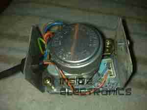
This is the internals of a motorised valve for central heating systems. Here the top is removed showing the motor & microswitch.

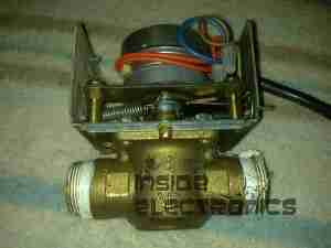
Left side of the valve, showing the gearing under the motor, & the valve body under the powerhead.

Right side of the valve, showing the sprung mechanism of the valve quadrant.

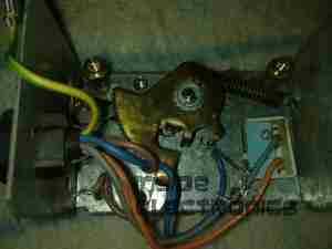
Here the motor has been removed from the powerhead, showing the microswitch & the sprung quadrant gear. This spring keeps the valve closed until the motor is energized. The motor remains energized to hold the valve open.

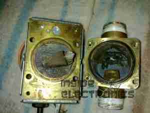
Here the valve body has been opened showing the internal components. The rubber valve rotates on the shaft, blocking the lower port of the valve when in operation.

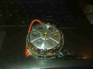
The motor’s protective cap has been removed here showing the rotor. This is a synchronous motor, of a special type for use in motorised valves. As the windings need to be continuously energized to hold the valve open, it is designed not to burn out under this load. 240v AC 50Hz, 5RPM.