Posted on Leave a comment

Narrowboating Quickies – Webasto Heater Exhaust Rehash

Since rebuilding the burner for the Webasto water heater on board nb Tanya Louise, I figured it was about time I sorted the exhaust out as well. The standard Eberspacher / Webasto type exhaust system components are shit. Nothing is properly gas tight, no matter how you build the system, due to how the pipe is constructed – it’s spiral ribbed stainless flexi tube, and even proper clamps don’t exert enough force to create a gas seal on the fittings, leaving gaps in the spiral for exhaust to leak out. Unfortunately I don’t have a photo of the old exhaust setup – it was however awful.

So to fix the problem of the messy setup, and to fix the issue of leaking exhaust gases, I got to work creating a custom system from 22mm copper pipe, brazing all the joints together.

Completed Exhaust
Completed Exhaust

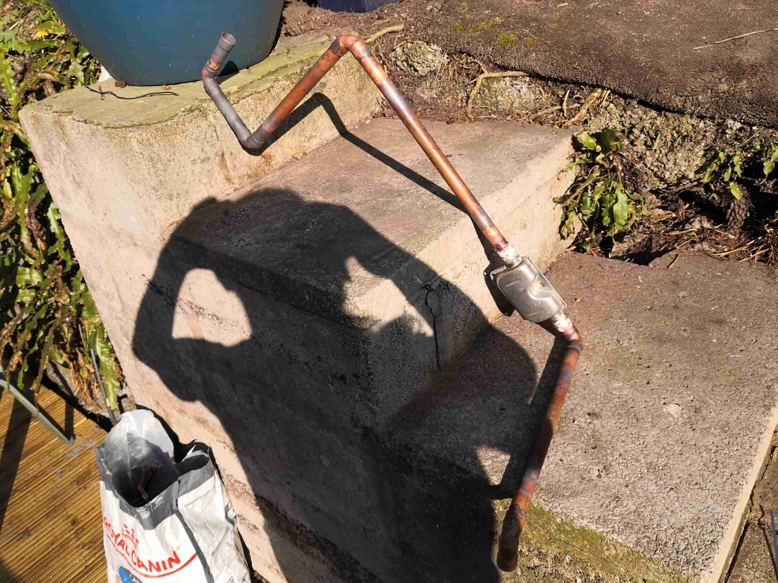
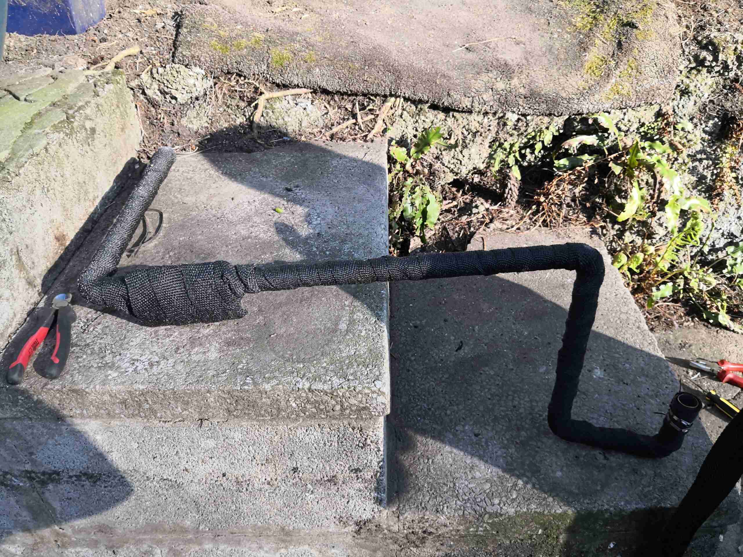
Here’s the completed system, matched to the location of the heater unit in the engine bay, and the exhaust skin fitting. The ends of the pipe are expanded with a hydraulic tool to allow them to fit onto the heater & skin fitting, these being too large for 22mm pipe normally.

Brazed Muffler
Brazed Muffler

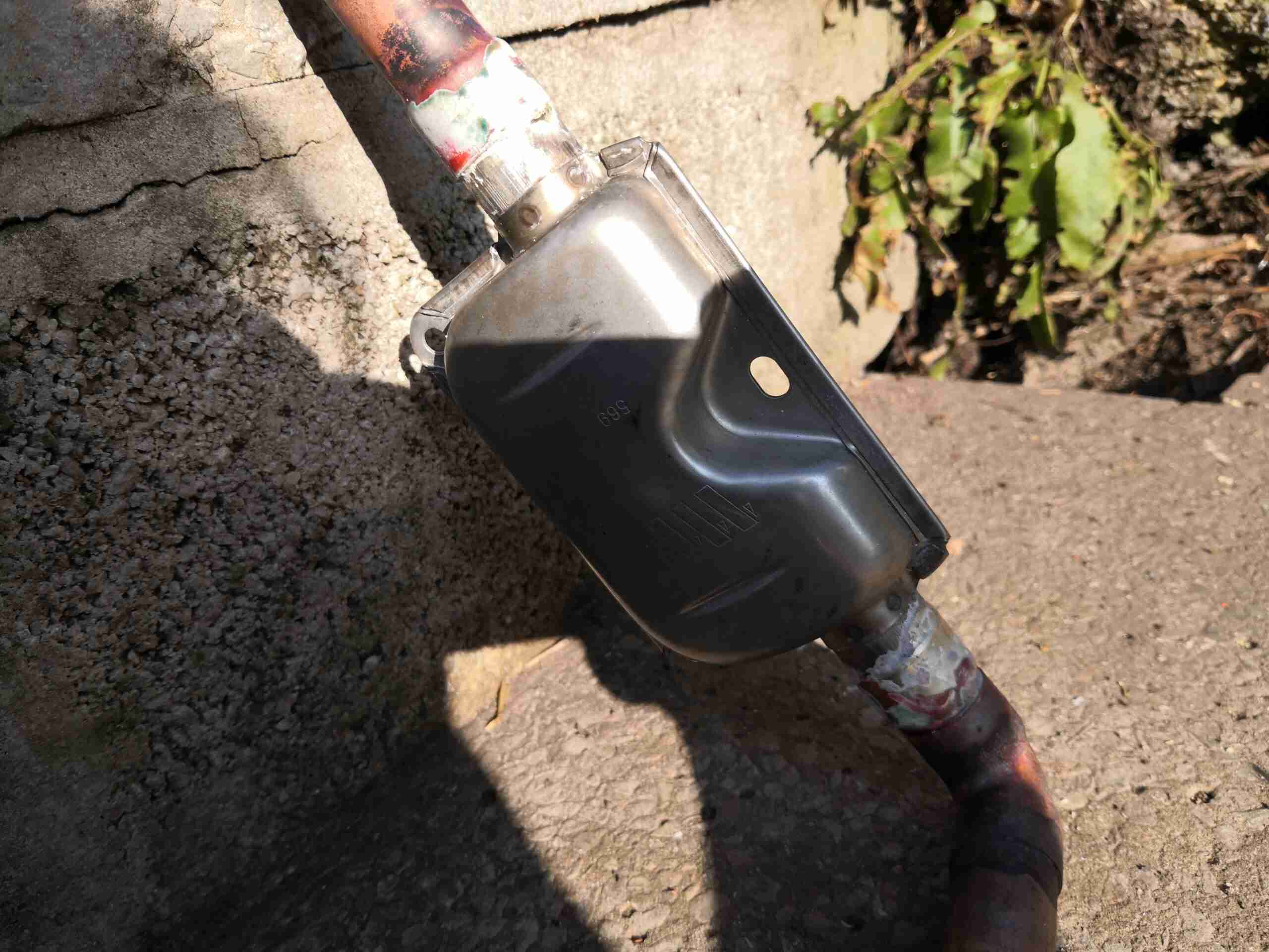
The muffler is also fully brazed to keep exhaust gases inside the exhaust. These are supplied just crimped together as they’re intended for use under vehicles. A sealed marine grade exhaust silencer is available, but very expensive. Again the copper pipe ends are expanded with the hydraulic tool to allow them to fit into place on the stainless tails. Brazing was done with 55% silver brazing rod.

Fibreglass Wrap
Fibreglass Wrap

To keep the heat away from sensitive parts in the engine bay, the entire assembly has been wrapped in fibreglass insulation tape, and secured with stainless steel ties. It’s important to use only stainless in these applications – the fibreglass wrap will hold any moisture in contact with all the parts, and mild steel will rapidly convert back into Iron Oxide 😉

Heater End
Heater End

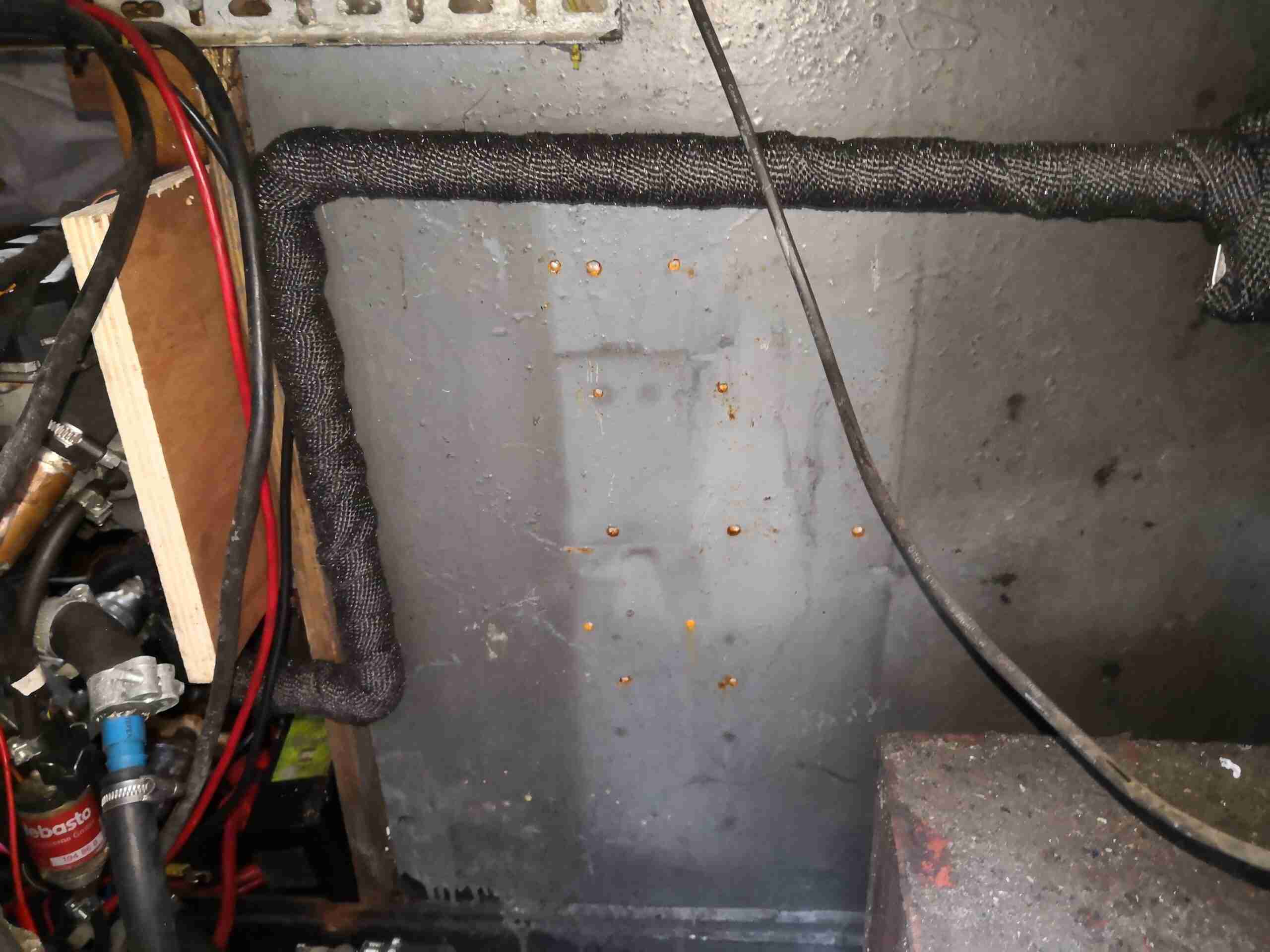
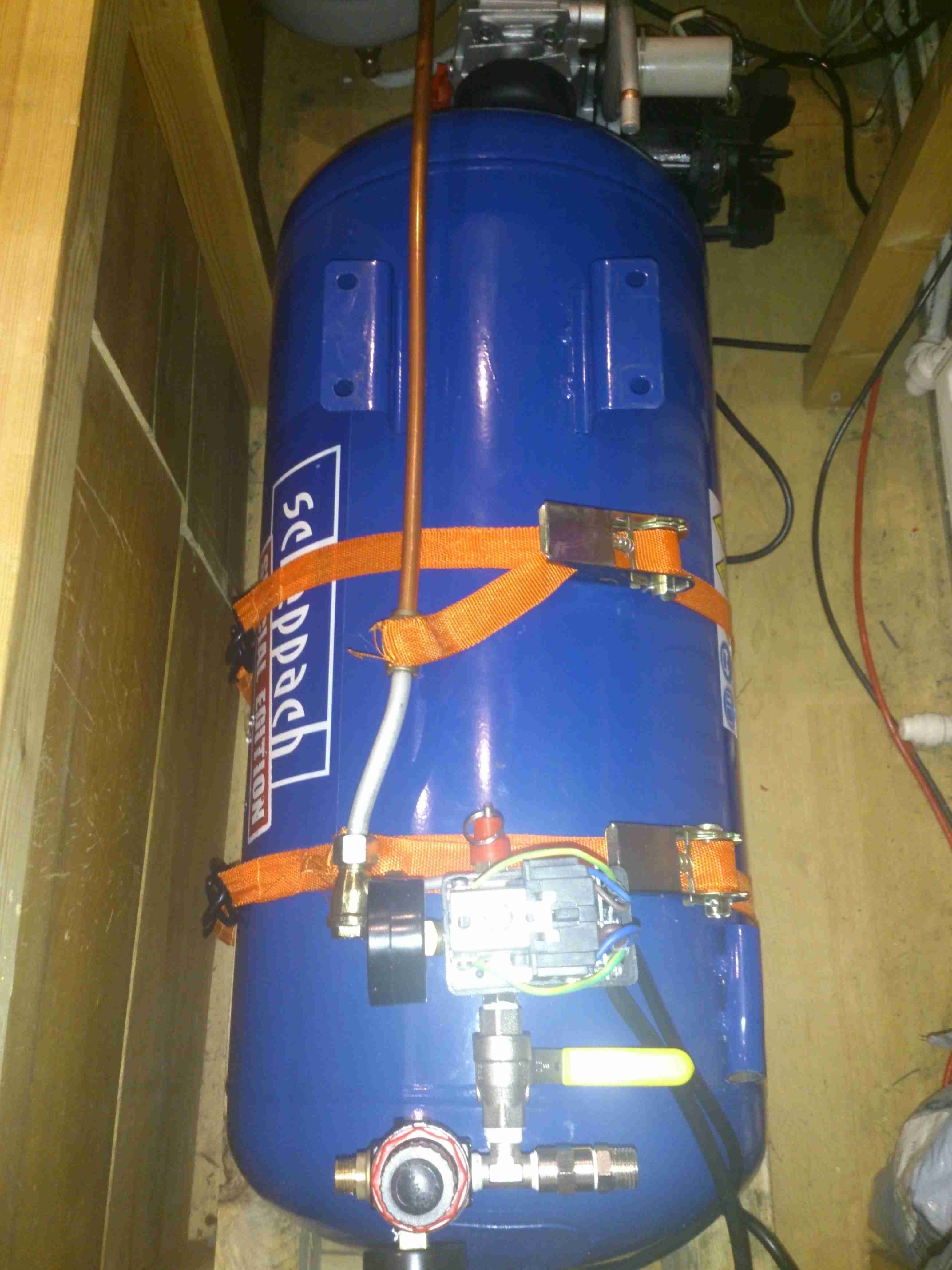
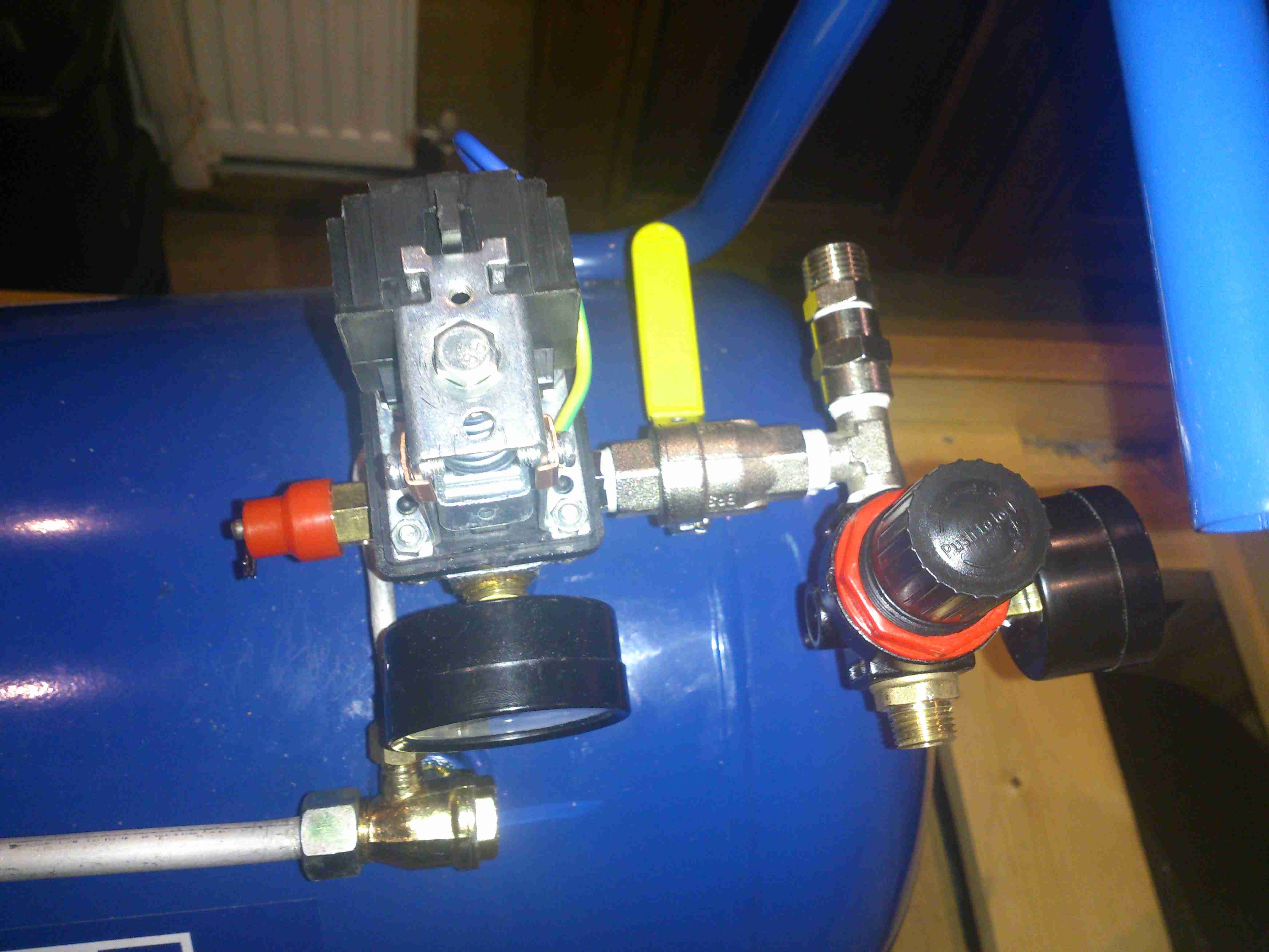
The heater itself is on the other side of the plywood board in the photo, the cooling water pipework can be seen on the lower left, along with the diesel dosing pump. The main fuel tank is just visible in the bottom right corner.

Skin Fitting Connection

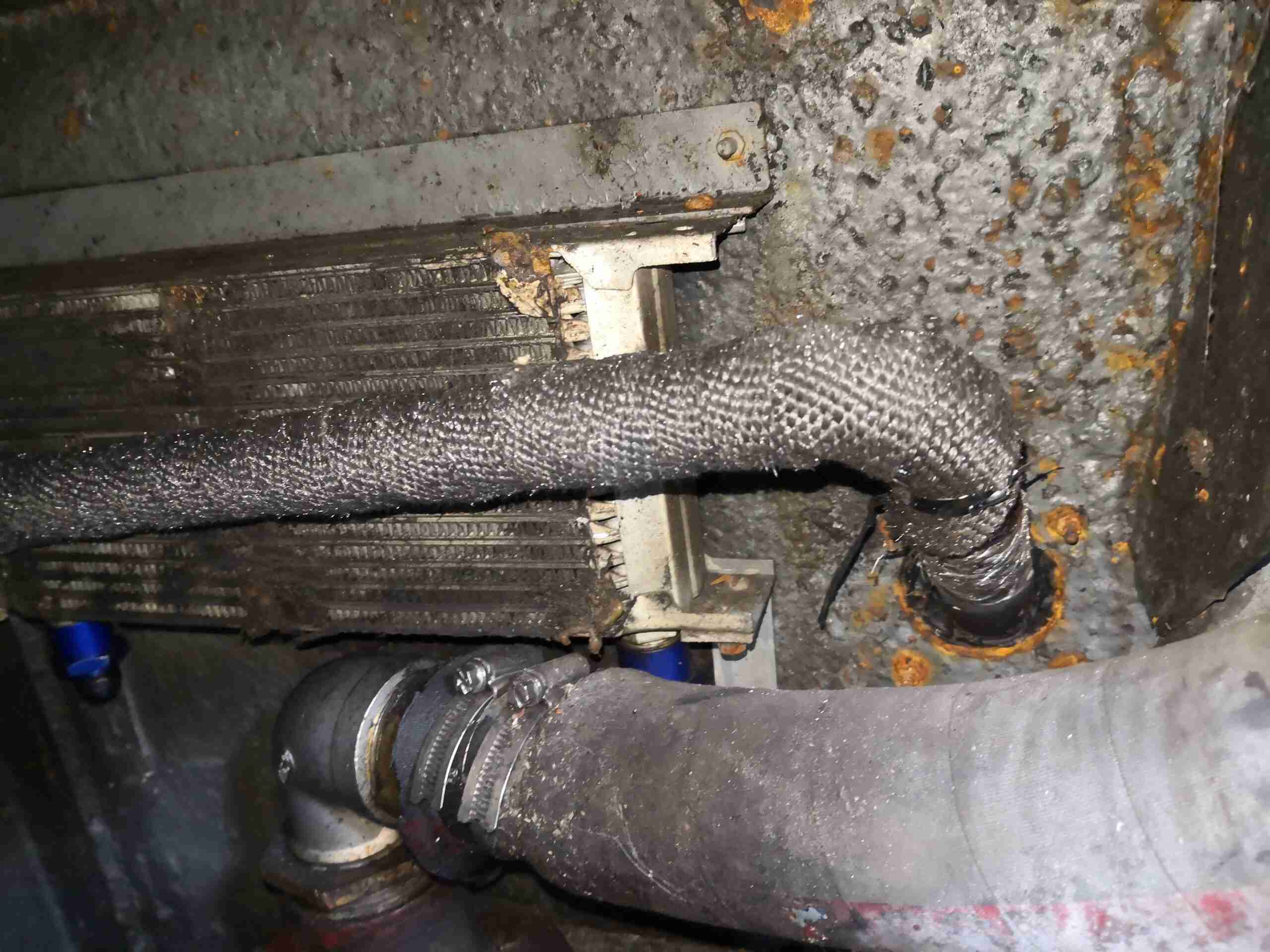
The other end is sized for a snug fit onto the exhaust skin fitting, just astern of the old oil cooler. This is set to be removed at some stage, and be replaced with an engine bay blower for ventilation.

Silencer
Silencer

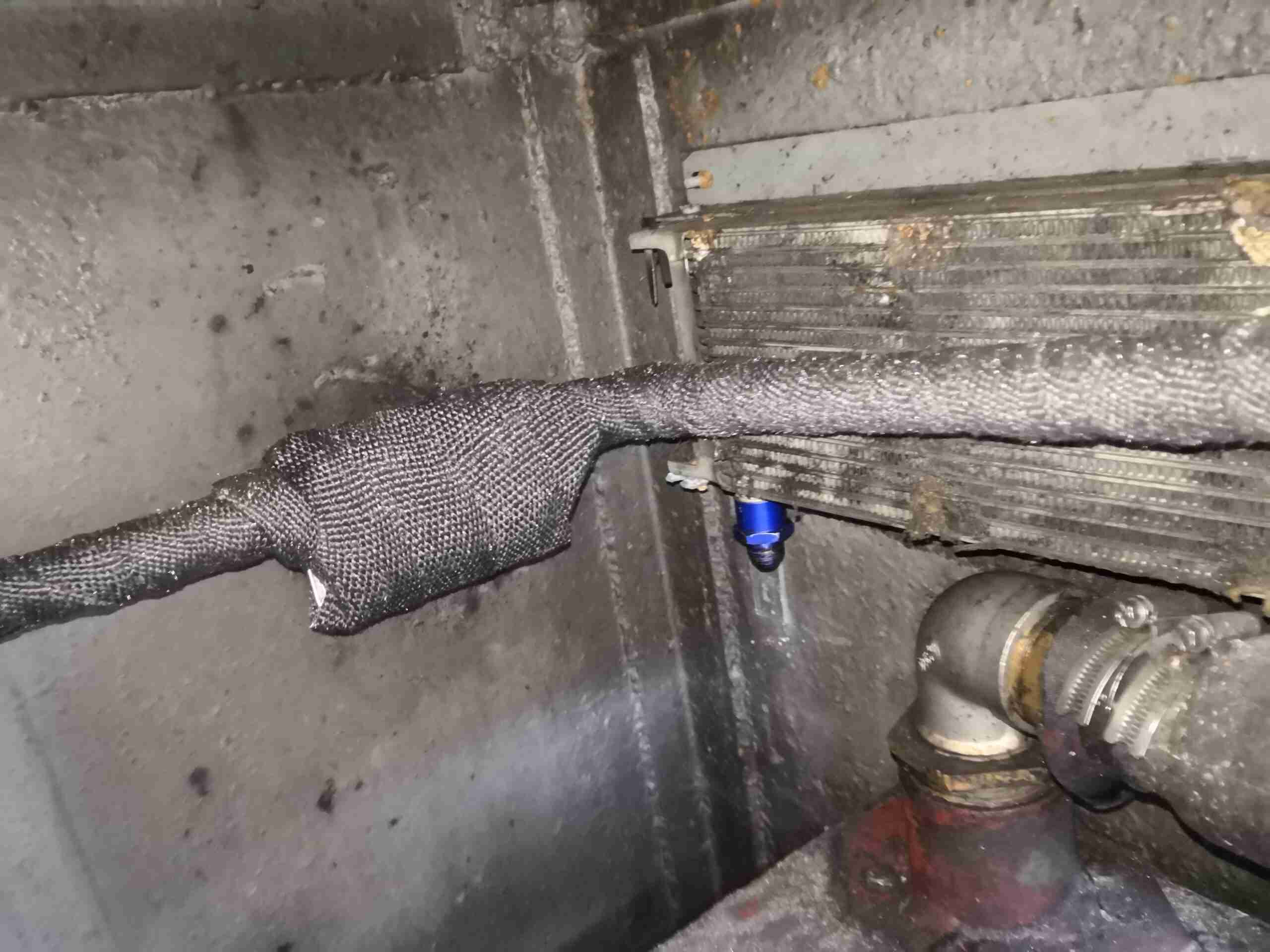
In the corner, next to the bulkhead sits the silencer.

In all, this setup also made the heater quieter, probably due to the longer length of exhaust pipework, which is now about 1.5 metres from the heater outlet to the skin fitting. This is a bonus – the exhaust of these heaters without any silencing sounds like a jet engine!


Posted on Leave a comment

Boating: Drydock Time – New Running Gear & Rudder Modifications

New Shaft & Prop
New Shaft & Prop

We’re now on the final leg of the jobs to be done on the boat! Above is the new prop & shaft, supplied to us by Crowther Marine over in Royton. To fit our current stern tube & gland, the shaft is the same diamter at 1-3/8″. Unfortunately no 4-blade props were available, so I had to go for a 17×11 left-hand, but with a much larger blade area than the old one.

Propellers
Propellers

Here’s the old prop on the right, with the new one on the left, amazing how different 1 inch of diameter actually looks. The opposite hand of the new prop makes no difference in our case, as I can simply switch the hoses to the hydraulic motor on the shaft to make everything reverse direction.

Stripper
Stripper

Above is the solution to my problem of no weed hatch – a Stripper Rope Cutter from Ambassador Marine. This device has some seriously viciously sharp cutting teeth to help clear any fouling from the prop in operation. Only time will tell if it’s effective at allowing me to stay out of the canal manually removing the crap!

Cutless Bearing
Cutless Bearing

We finally got the bearing mount finished, by S Brown Engineering in Stockport. This is made from Stainless steel to stop the bearing corroding in place & becoming a real arse to replace. Set screws are fitted to make sure the bearing doesn’t move in service.
Attached to the side of the bearing housing is the fixed blade mounting for the Stripper Rope Cutter.

Bearing Test Fit
Bearing Test Fit

Above is everything fitted to the shaft for a test before the gear went into it’s home in the stern tube. The Stripper mounts behind the prop, clamped to the shaft. The 3 moving blades move against the fixed blade like a mechanised pair of scissors.

Bearing Strut Welding

10mm steel plate has been used to make the strut for the bearing tube, welded together. In the case of the joint between the stainless tube & the carbon steel strut, special welding rods were needed, at the price of £2 a rod! Using mild steel rods to weld stainless could result in cracking of the welds. Not a good thing on a prop shaft support bearing.

Sand Blasted Hull
Sand Blasted Hull

Most of the old tube has been cut away to make room for the new bearings, and the bottom of the hull has been sand-blasted ready for welding.

Running Gear Mounted

The bearing mount is welded to the hull, the Stripper & the prop are fitted to the end of the shaft. There’s 1.5″ of clearance from the blade tips to the hull plating. The rudder has about an inch of clearance to the end of the shaft.

Rudder Fence
Rudder Fence

To help keep the prop wash down, directing more of the force into moving the vessel rather than creating a nice rooster tail, a pair of plates has been welded onto the rudder. These also provide a handy step should someone fall in ;).

Posted on Leave a comment

Boating: Drydock Time – Running Gear Replacement

Progress
Progress

Things are coming along nicely with this year’s drydock operations.

Blacking - Second Coat
Blacking – Second Coat

Shes looking much better, the second coat of bitumen blacking is on, we’re going to continue at a coat a day until we’re due back in the water.

Shaft Tube Damage
Shaft Tube Damage

I’ve now removed the shaft from the stern tube to gain better access, now the full extent of the damage to the tube can be seen. There’s nothing left at all of the old bearing, which on this boat was simply a nylon bushing pressed into the end of the tube. (I knew it was crap the last time we were out, but ran out of time to get a fix done).
The stainless shaft, having lost it’s support bearing at some point, has been running on the inside of the steel tube, and has neatly chewed straight through it.

Prop Shaft
Prop Shaft

Here’s the prop shaft removed from the boat – possibly the longest shaft I’ve ever seen on a narrowboat at 6′ 2″. Unfortunately, the fact that it lost the bearing has also damaged the shaft itself, this will have to be replaced.

Prop Taper
Prop Taper

Here’s the end of the shaft that would run in the end bearing, it’s badly scored & fitting a new bearing to this shaft would cause failure very quickly. The taper on the end isn’t much better, and a loose fit in the prop has done some damage there also.

Old Prop
Old Prop

Here’s the old prop – a 16×12 that was only fitted a few years ago. This will be replaced with a new 4-blade prop, as this one is far too small for the size of the boat & installed power. Installing a larger diameter prop isn’t possible due to clearance from the swim, so I’ll have to get a more steeply pitched prop, with 4-blades for increased contact area with the water.

Posted on Leave a comment

Boating: Drydock Time – The Inspection

Drydock
Drydock

It’s that time again, so the boat is out of the water for it’s 3-yearly maintenance. Some things over the past few months have been bugging me, namely a pronounced vibration in the running gear while underway. (Issue was easy to spot here!).

10-Ton Jack
10-Ton Jack

nb Tanya Louise being a very odd vessel, she has quite a significant keel, so once the dock was drained, some manual jacking was required to get her level on the blocks. Without this extra work there is such a pronounced heel that it’s impossible to do anything on board.

Chocks
Chocks

On the opposite side, wooded blocks are placed for the bottom of the hull to rest against. Jacking up a 58-ft 25-ton boat by hand onto some timbers was nerve-wracking to say the very least!

The bottom of the hull has already been jet-washed to remove 3-year’s worth of slime, weed growth & the old blacking. First job is to get a fresh coat of paint on.

Running Gear
Running Gear

Looking under the hull shows the reason for the high level of vibration – the prop shaft has actually *worn through* the bearing & stern tube, to the extent that there’s not much left of the assembly! The only thing holding the shaft in place at this stage is the stuffing box inside the boat & the shaft coupling to the hydraulic motor.
, stern tube,
A replacement standard-issue Cutless bearing will be fitted, after the remains of the old tube are cut back to make room. To facilitate mounting the bearing, a custom stainless P bracket is being made at a local engineers, for me to weld onto the bottom of the hull.

(Surprised we didn’t lose the shaft, lucky that I kept pestering to get her out of the water!).

More to come as work progresses!

Posted on Leave a comment

nb Tanya Louise – Compressor Install

Compressed air is a rather useful power source, especially when all maintenance is done by the on board crew instead of by boatyards.

Screwfix had a good deal on a 50L 3.5CFM air compressor, to save space this has been permanently mounted in a free space & air will be piped to where it is needed from a central point.

Because of the total height of the machine, the compressor itself has been unbolted from the tank, a copper line connecting the two back together at a larger distance.

Bearers
Bearers

In one of the very few free spaces available, under a bunk. A pair of timbers has been screwed to the floor to support the tank.

Tank Installed
Tank Installed

The tank is strapped to the wooden supports with a pair of ratchet straps, the compressor itself can be seen just behind the tank. The copper line on the top of the tank is going back to be connected to the compressor outlet.

Air Fittings
Air Fittings

Compressor control remains on top of the tank, the pressure switch & relief valve centre. After an isolation valve, the feed splits, the regulator installed will be feeding the air horn with 20PSI, replacing the existing automotive-style 12v air pump. The currently open fitting will be routed to a quick connect on the bulkhead. This will be accessible from the front deck, an air hose can be fitted to get a supply anywhere on board.

More to come when the rest of the system gets installed!

73s for now.