Posted on Leave a comment

Turbine Fuel Pump Extreme Teardown

Turbine Fuel Pump
Turbine Fuel Pump

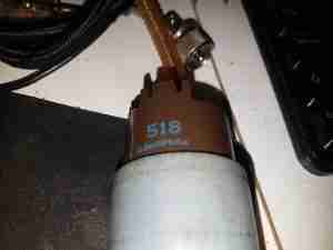
Here’s a destructive teardown of an automotive in-tank turbine fuel pump, used on modern Petrol cars. These units sit in the tank fully immersed in the fuel, which also circulates through the motor inside for cooling. These pumps aren’t serviceable – they’re crimped shut on both ends. Luckily the steel shell is thin, so attacking the crimp joint with a pair of mole grips & a screwdriver allowed me inside.
End Bell
End Bell

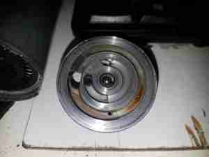
The input endbell of the pump has the fuel inlet ports, the channels are visible machined into the casting. There’s a pair of channels for two pump outputs – the main fuel rail to the engine, and an auxiliary fuel output to power a venturi pump. The fuel pump unit sits inside a swirl pot, which holds about a pint of fuel. These are used to ensure the pump doesn’t run dry & starve the engine when the tank level is low & the car is being driven hard. The venturi pump draws fuel from the main tank into the swirl pot. A steel ball is pressed in to the end bell to provide a thrust bearing for the motor armature.
Turbine Impeller
Turbine Impeller

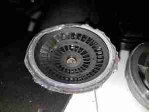
The core of the pump is this impeller, which is similar to a side-channel blower. From what I’ve been able to find these units supply pressures up to about 70PSI for the injector rail. The outside ring is the main fuel pump, while the smaller inner one provides the pressure to run the venturi pump.
Pump Housing
Pump Housing

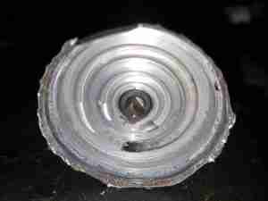
The other side of the machined pump housing has the main output channel, with the fuel outlet port at the bottom. The motor shaft is supported in what looks like a carbon bearing.
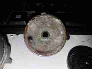
Midsection
Midsection

Removing the pump intermediate section with the bearing reveals quite a bit of fungus – it’s probably been happy sat in here digesting what remains of the fuel.
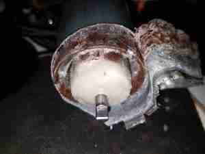
Armature Exposed
Armature Exposed

Some peeling with mole grips allows the motor to come apart entirely. The drive end of the armature is visible here.
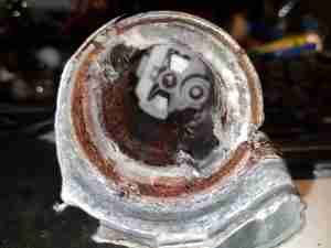
Motor Can
Motor Can

The outer shell of the motor holds yet more fungus, along with some rust & the pair of ceramic permanent magnets.
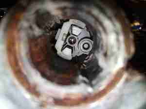
Brushes
Brushes

The other end of the pump has the brush assembly, and the fuel outlet check valve to the right. The bearing at this end is just the plastic end cap, since there are much lower forces at this end of the motor. The fuel itself provides the lubrication required.
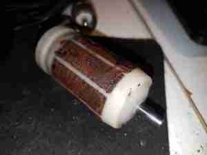
Potted Armature
Potted Armature

With the armature pulled out of the housing, it’s clear that there’s been quite a bit of water in here as well, with the laminations rusting away. This armature is fully potted in plastic, with none of the copper windings visible.
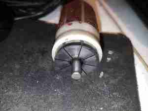
Carbon Commutator
Carbon Commutator

The commutator in these motors is definitely a strange one – it’s axial rather than radial in construction, and the segments are made of carbon like the brushes. No doubt this is to stop the sparking that usually occurs with brushed motors – preventing ignition of fuel vapour in the pump when air manages to get in as well, such as in an empty tank.
Posted on Leave a comment

Boating: Drydock Time – Running Gear Replacement

Progress
Progress

Things are coming along nicely with this year’s drydock operations.

Blacking - Second Coat
Blacking – Second Coat

Shes looking much better, the second coat of bitumen blacking is on, we’re going to continue at a coat a day until we’re due back in the water.

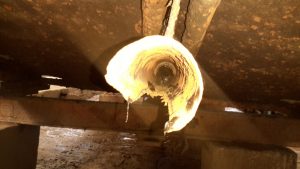
Shaft Tube Damage
Shaft Tube Damage

I’ve now removed the shaft from the stern tube to gain better access, now the full extent of the damage to the tube can be seen. There’s nothing left at all of the old bearing, which on this boat was simply a nylon bushing pressed into the end of the tube. (I knew it was crap the last time we were out, but ran out of time to get a fix done).
The stainless shaft, having lost it’s support bearing at some point, has been running on the inside of the steel tube, and has neatly chewed straight through it.

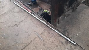
Prop Shaft
Prop Shaft

Here’s the prop shaft removed from the boat – possibly the longest shaft I’ve ever seen on a narrowboat at 6′ 2″. Unfortunately, the fact that it lost the bearing has also damaged the shaft itself, this will have to be replaced.

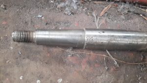
Prop Taper
Prop Taper

Here’s the end of the shaft that would run in the end bearing, it’s badly scored & fitting a new bearing to this shaft would cause failure very quickly. The taper on the end isn’t much better, and a loose fit in the prop has done some damage there also.

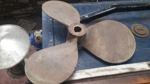
Old Prop
Old Prop

Here’s the old prop – a 16×12 that was only fitted a few years ago. This will be replaced with a new 4-blade prop, as this one is far too small for the size of the boat & installed power. Installing a larger diameter prop isn’t possible due to clearance from the swim, so I’ll have to get a more steeply pitched prop, with 4-blades for increased contact area with the water.

Posted on Leave a comment

Boating: Drydock Time – The Inspection

Drydock
Drydock

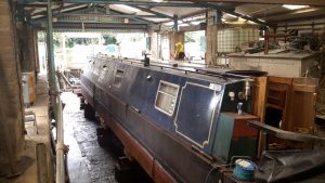
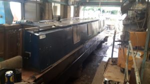
It’s that time again, so the boat is out of the water for it’s 3-yearly maintenance. Some things over the past few months have been bugging me, namely a pronounced vibration in the running gear while underway. (Issue was easy to spot here!).

10-Ton Jack
10-Ton Jack

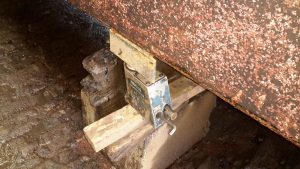
nb Tanya Louise being a very odd vessel, she has quite a significant keel, so once the dock was drained, some manual jacking was required to get her level on the blocks. Without this extra work there is such a pronounced heel that it’s impossible to do anything on board.

Chocks
Chocks

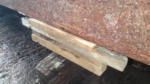
On the opposite side, wooded blocks are placed for the bottom of the hull to rest against. Jacking up a 58-ft 25-ton boat by hand onto some timbers was nerve-wracking to say the very least!

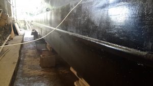
The bottom of the hull has already been jet-washed to remove 3-year’s worth of slime, weed growth & the old blacking. First job is to get a fresh coat of paint on.

Running Gear
Running Gear

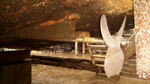
Looking under the hull shows the reason for the high level of vibration – the prop shaft has actually *worn through* the bearing & stern tube, to the extent that there’s not much left of the assembly! The only thing holding the shaft in place at this stage is the stuffing box inside the boat & the shaft coupling to the hydraulic motor.
, stern tube,
A replacement standard-issue Cutless bearing will be fitted, after the remains of the old tube are cut back to make room. To facilitate mounting the bearing, a custom stainless P bracket is being made at a local engineers, for me to weld onto the bottom of the hull.

(Surprised we didn’t lose the shaft, lucky that I kept pestering to get her out of the water!).

More to come as work progresses!

Posted on Leave a comment

Mini USB Soldering Iron

USB Soldering Iron
USB Soldering Iron

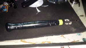
Here’s a novel little gadget, a USB powered soldering iron. The heating tip on these is very small & might be useful for very small SMD work. Bigger joints not so much, as it’s only rated at 8W. (Still breaks the USB standard of 2.5W from a single port).

These irons aren’t actually too bad to use, as long as the limitations in power are respected. Since nearly everything has a USB power port these days, it could make for a handy emergency soldering iron.

Heater Socket
Heater Socket

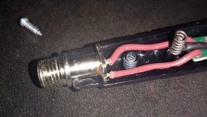
The heater & soldering bit are a single unit, not designed to be replaced separately. (I’ve not managed to find replacement elements, but at £3 for the entire iron, it would be pretty pointless).
Above is the socket where the heater plugs in, safely isolating the plastic body from any stray heat.

DC Input Jack
DC Input Jack

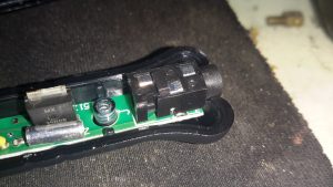
The DC input is a 3.5mm audio jack, a non-standard USB to 3.5mm jack cable is supplied. Such non-standard cables have the potential to damage equipment that isn’t expecting to see 5v on an audio input if it’s used incorrectly.

Touch Sensor & LED
Touch Sensor & LED

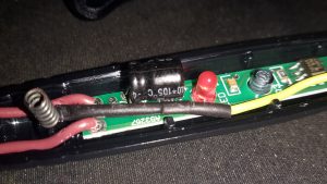
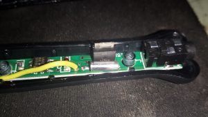
There isn’t actually a switch on this unit for power management, but a clever arrangement of a touch button & vibration switch. The vertical spring in the photo above makes contact with a steel ball bearing pressed into the plastic housing, forming the touch contact.

MOSFET
MOSFET

The large MOSFET here is switching the main heater current, the silver cylinder in front is the vibration switch, connected in parallel with the touch button.

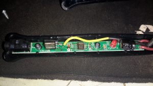
PCB
PCB

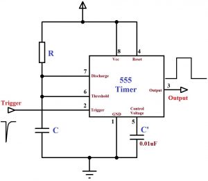
The main controller is very simple. It’s a 555 timer configured in monostable mode. Below is a schematic showing the basic circuit.

555 Monostable
555 Monostable

Big Clive also did a teardown & review of this iron. Head over to YouTube to watch.

Posted on Leave a comment

Eaton Variable Displacement Hydraulic Pump Repair

In the process of going through the boat mechanically, ready for this year’s cruising season, some damage was discovered on the face of the main hydraulic propulsion pump that drives the propeller.

Face Damage
Face Damage

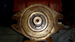
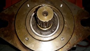
Here’s the front face of the pump, with it’s drive shaft. The circular ridge isn’t supposed to be there, it’s meant to be completely flat.
The central hub of the Centaflex coupling managed to loosen itself on the shaft (they’re pretty badly designed), and when the steel hub moved backward, it ground a very nice recess into the cast iron pump housing.
This managed to get deep enough where it compromised the circlip groove that holds both the oil seal & the mainshaft thrust bearing in place.

Spacer Ring
Spacer Ring

To save a considerable amount of cash (replacing the entire base casting of the pump would be hideously expensive), a 6mm ring was machined from steel, to hold the seal in place.
The face of the pump was then drilled & tapped for M5 screws.

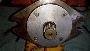
Plate Fitted
Plate Fitted

Above, the repair plate has been fitted, with the spacer ring sandwiched between it & the oil seal, securing everything in place.

Having a replaceable wear plate screwed to the front of the pump also allows for easy future repair if the coupling moves again.

Posted on Leave a comment

HPI Nitrostar F4.6 Ignition Conversion

As there was no other online example of someone converting a glow/nitro car engine onto CDI ignition, I thought I would document the highlights here.
The engine is currently still running on glow fuel, but when the required fuel lines arrive I will be attempting the switch over to 2-Stroke petrol mix. This should definitely save on fuel costs.

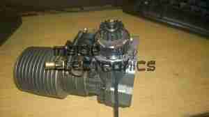
The engine in this case is a HPI NitroStar F4.6 nitro engine, from a HPI Savage X monster truck.

F4.6 Engine
F4.6 Engine

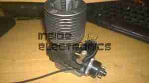
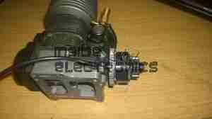
Above is the converted engine with it’s timing sensor. As The installation of this was pretty much standard, a complete strip down of the engine was required to allow the drilling & tapping of the two M3x0.5 holes to mount the sensor bracket to. The front crankshaft bearing has to be drifted out of the crankcase for this to be possible.

Ignition Hall Sensor

Detail of the ignition hall sensor. The bracket has to be modified to allow the sensor to face the magnet in the flywheel. Unlike on an Aero engine, where the magnet would be on the outside edge of the prop driver hub, in this case the hole was drilled in the face of the flywheel near the edge & the magnet pressed in. The Hall sensor is glued to the modified bracket with the leads bent to position the smaller face towards the back of the flywheel.
The clearance from the magnet to sensor is approx. 4mm.

Flywheel Magnet
Flywheel Magnet

Detail of the magnet pressed into the flywheel. A 3.9mm hole was drilled from the back face, approx 2mm from the edge, & the magnet pressed into place with gentle taps from a mallet & drift, as I had no vice to hand.
Initial timing was a little fiddly due to the flywheel only being held on with a nut & tapered sleeve, so a timing mark can be made inside the rear of the crankcase, across the crank throw & case to mark the 28 degree BTDC point, the flywheel is then adjusted to make the ignition fire at this point, before carefully tightening the flywheel retaining nut to ensure no relative movement occurs.
The slots in the sensor bracket allow several degrees of movement to fine adjust the timing point once this rough location has been achieved.

1/4"-32 Spark Plug
1/4″-32 Spark Plug

Definitely the tiniest spark plug I’ve ever seen, about an inch long. Some trouble may be encountered with this on some engines – the electrodes stick out about 2mm further into the combustion chamber than a standard glow plug does. This causes the ground electrode to hit the top of the piston crown. (This happens on the HPI NitroStar 3.5 engine). The addition of another copper washer under the plug before tightening should cure this problem.

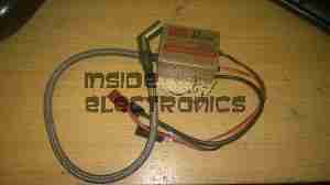
RcExl CDI Ignition Module

Ignition module. Due to the depth of the plug in the heatsink head on these engines, I will have to modify the plug cap to straighten it out, as it will not fit in this configuration.
However, ignition modules are available from HobbyKing with straight plug caps, this makes modification unnecessary

The ignition & components used on this system were obtained from JustEngines.

Posted on Leave a comment

Dremel MultiPro

Front
Front

Here we have a Dremel MultiPro rotary tool, a main powered 125W 33,000RPM bit of kit.

Motor Assembly
Motor Assembly

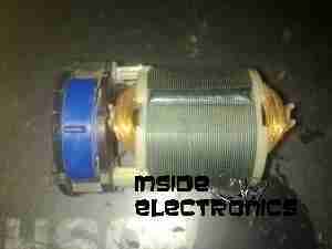
Here the field & controller assembly is removed from the casing.

Armature
Armature

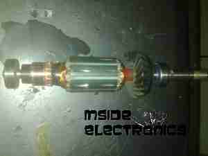
Here is the armature, which rotates at up to 33,000RPM. The brushes rise against the commutator on the left, next to the bearing, the cooling fan is on the right hand side on the power output shaft, the chuck attaches at the far right end of the shaft.

Speed Controller & Brush Box

Here is the speed controller unit, inside is an SCR phase angle speed controller, to vary the speed of the motor from 10,000RPM to the full rated speed of 33,000RPM.

Mains Filter
Mains Filter

This is the mains filter on the input to the unit, stops stray RF from the motor being radiated down the mains cable.