Posted on Leave a comment

Power Supply Cooling Update

While I’m waiting for the fan controllers to arrive for the new cooling fans, I figured I’d get them fitted into the cases of the supplies & just have them run at minimum speed for now.

Fan Fitted
Fan Fitted

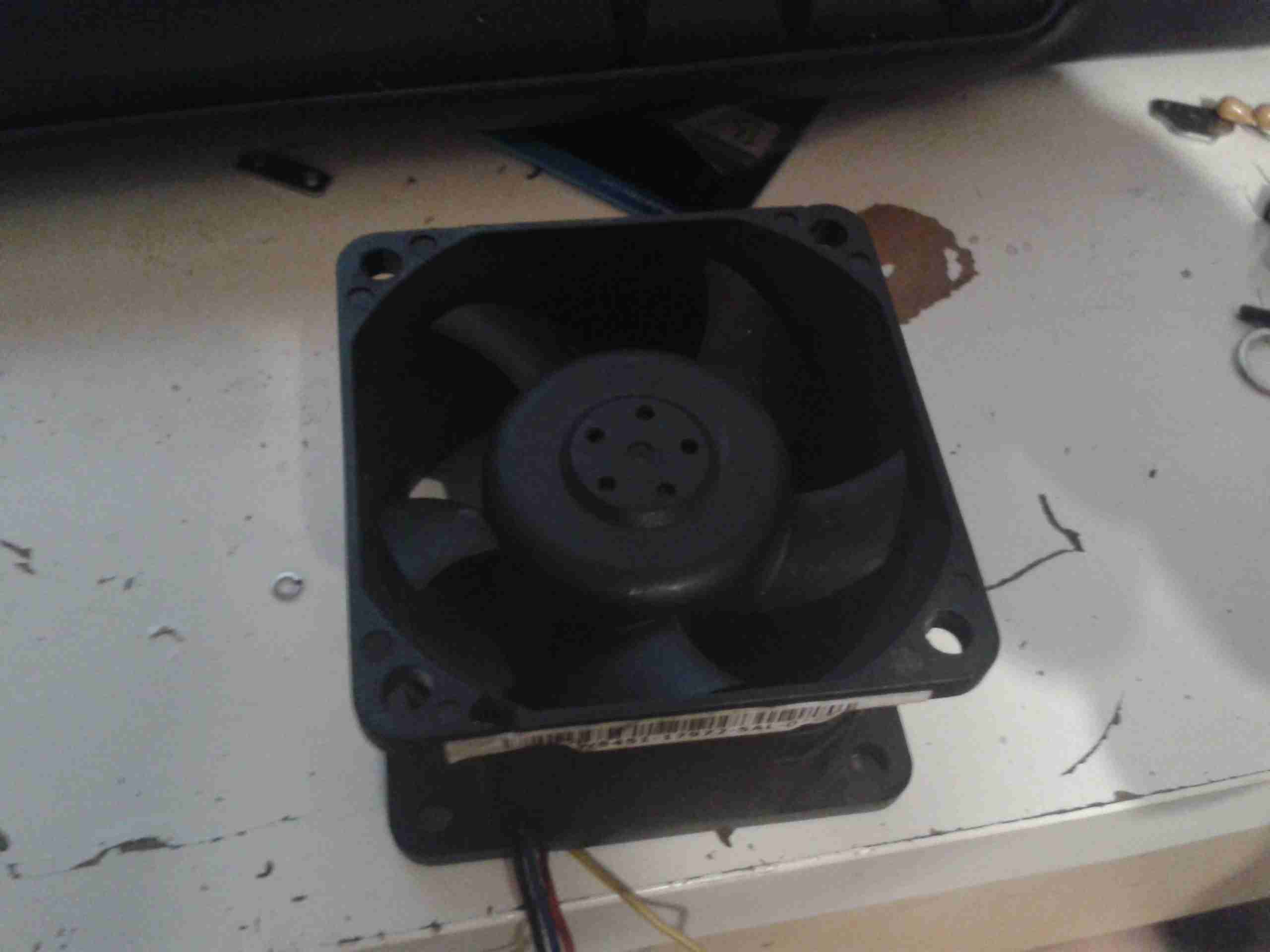
After removing the original small fan, I cut a larger square hole in the panel to fit the 60mm version. These fans only fit with some minor adjustment to the top & bottom mouldings, but the look isn’t too bad once the covers are back on. The wiring is routed through a small hole next to the fan itself.

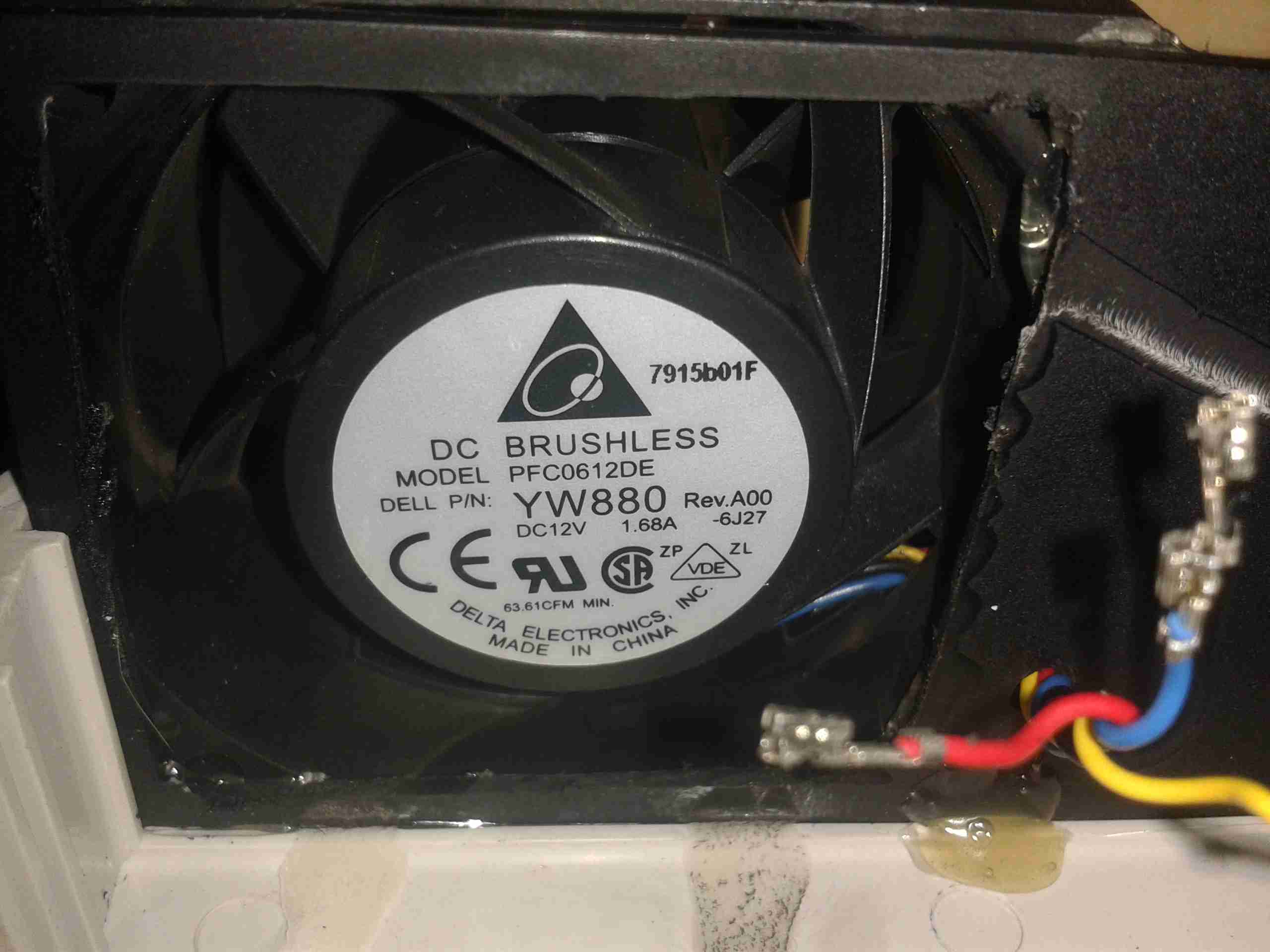
I’ve also upgraded on the fans again – these are PFC0612DE, with a higher airflow of ~70CFM at 12,000RPM.

To get the fans to run at minimum speed, the PWM control wire is connected directly to GND.

More to come when the controllers arrive!

Posted on Leave a comment

DIY SMPS Cooling

The power supplies I have recently built from surplus Cisco switch boards have started displaying a rather irritating problem – continual load of over 9A causes the supplies to shut down on overheat.

This was partially expected, as the original switches that these supplies came from are cooled by a monster of a centrifugal blower that could give a Dyson a run for it’s money. The problem with these fans is that they’re very loud, draw a lot of power (3-4A) and aren’t small enough to fit into the case I’ve used for the project.

The solution of course, is a bigger fan – I’ve got some Delta AFB0612EHE server fans, these are very powerful axial units, shifting 60CFM at 11,000RPM, with a power draw of 1.12A.
They’re 60mm diameter, so only just fit into the back of the case – although they stick out of the back by 40mm.

Monster Fan
Monster Fan

Here’s the fan, not the beefiest I have, but the beefiest that will fit into the available space.
These will easily take fingers off if they get too close at full speed, so guards will definitely be required.

To reduce the noise (they sound like jet engines at full pelt), I have ordered some PWM controllers that have a temperature sensor onboard, so I can have the fan run at a speed proportional to the PSU temperature. I will probably attach the sensor to the output rectifier heatsink, since that’s got the highest thermal load for it’s size.

More to come when parts arrive!

73s for now 🙂

Posted on Leave a comment

nb Tanya Louise Hydraulic Generator

Hydraulic Generator Unit

To accompany the previous two posts about hydraulic generators & their components, here is the actual generator unit itself.

Rated at 8.5kVa 230v AC, this will providea mains supply while the narrowboat is away from her home mooring.

This unit will be attached to the side of the hull in the engine room on rubber vibration isolation mounts, behind the main hydraulic oil tank & is driven from the small gear pump attached to the back of the main propulsion hydraulic pump unit.
Operating pressure is 175 bar, 21L/m flow rate to achieve the 3,000RPM rotor speed for 50Hz mains frequency.

Generator Specifications
Posted on Leave a comment

Dremel MultiPro

Front
Front

Here we have a Dremel MultiPro rotary tool, a main powered 125W 33,000RPM bit of kit.

Motor Assembly
Motor Assembly

Here the field & controller assembly is removed from the casing.

Armature
Armature

Here is the armature, which rotates at up to 33,000RPM. The brushes rise against the commutator on the left, next to the bearing, the cooling fan is on the right hand side on the power output shaft, the chuck attaches at the far right end of the shaft.

Speed Controller & Brush Box

Here is the speed controller unit, inside is an SCR phase angle speed controller, to vary the speed of the motor from 10,000RPM to the full rated speed of 33,000RPM.

Mains Filter
Mains Filter

This is the mains filter on the input to the unit, stops stray RF from the motor being radiated down the mains cable.

Posted on Leave a comment

Hair Dryer

Housing
Housing

This is a 1500W hairdryer, death caused by thermal switch failure.

Switch
Switch

This is the switch unit. Attached are two suppression capacitors & a blocking diode. Cold switch is on right.

Heating Element
Heating Element

Heating element unit removed from housing. Coils of Nichrome wire heat the air passing through the dryer. Fan unit is on right.

Thermal Switch
Thermal Switch

Other side of the heating element unit, here can be seen the thermal switch behind the element winding. (Black square object).

Fan Motor
Fan Motor

The fan motor in this dryer is a low voltage DC unit, powered through a resistor formed by part of the heating element to drop the voltage to around 12-24v. Mounted on the back of the motor here is a rectifier assembly. Guide vanes are visible around the motor, to straighten the airflow from the fan blades.

Fan
Fan

5-blade fan forces air through the element at high speed. Designed to rotate at around 13,000RPM.