A few months ago I did a teardown on this Anker PowerPort Speed 5 USB charger, but I didn’t get round to detailing the conversion to 12v I had to do, so I’ll get to that now I’ve got a couple more to convert over.
Power Module
Here’s the internals of the Anker charger once I’ve removed the casing – which like many things these days, is glued together. (Joints can be cracked with a screwdriver handle without damaging the case). There’s lots of heatsinking in here to cool the primary side switching devices & the pot core transformers, so this is the first thing to get removed.
Heatsink Removed
Once the heatsink has been removed, the pot core transformers are visible, wrapped in yellow tape. There’s some more heatsink pads & thermal grease here, to conduct heat better. The transformers, primary side switching components & input filter capacitor have to go.
Primary Side Components Removed
Here’s the PCB once all the now redundant mains conversion components have been deleted. I’ve left the input filtering & bridge rectifier in place, as this solves the issue of the figure-8 cable on the input being reversible, polarity of the input doesn’t matter with the bridge. I’ve removed the main filter capacitor to make enough room for the DC-DC converters to be fitted.
Tails Installed
Installing the tails to connect everything together is the next step, this charger requires two power supplies – the QC3 circuits need 14.4v to supply the multi-voltage modules, the remaining 3 standard ports require 5v. The DC input tails are soldered into place where the main filter capacitor was, while the outputs are fitted to the spot the transformer secondary windings ended up. I’ve left the factory Schottky rectifiers in place on the secondary side to make things a little more simple, the output voltages of both the DC-DC converters does need to be increased slightly to compensate for the diode drops though. I’ve also bypassed the mains input fuse, as at 12v the input current is going to be substantially higher than when used on mains voltage.
DC-DC Converters Installed
With a squeeze both the boost converter & the buck converter fit into place on the PCB.
I was recently given a pretty nice LED backlit 1080p LG monitor, with the instruction that it wouldn’t power on correctly. The monitor would power on as far as the standby light, but when fully powered on, would flash the backlight momentarily then shut down. A power supply issue was immediately suspected.
LCD Logic Board
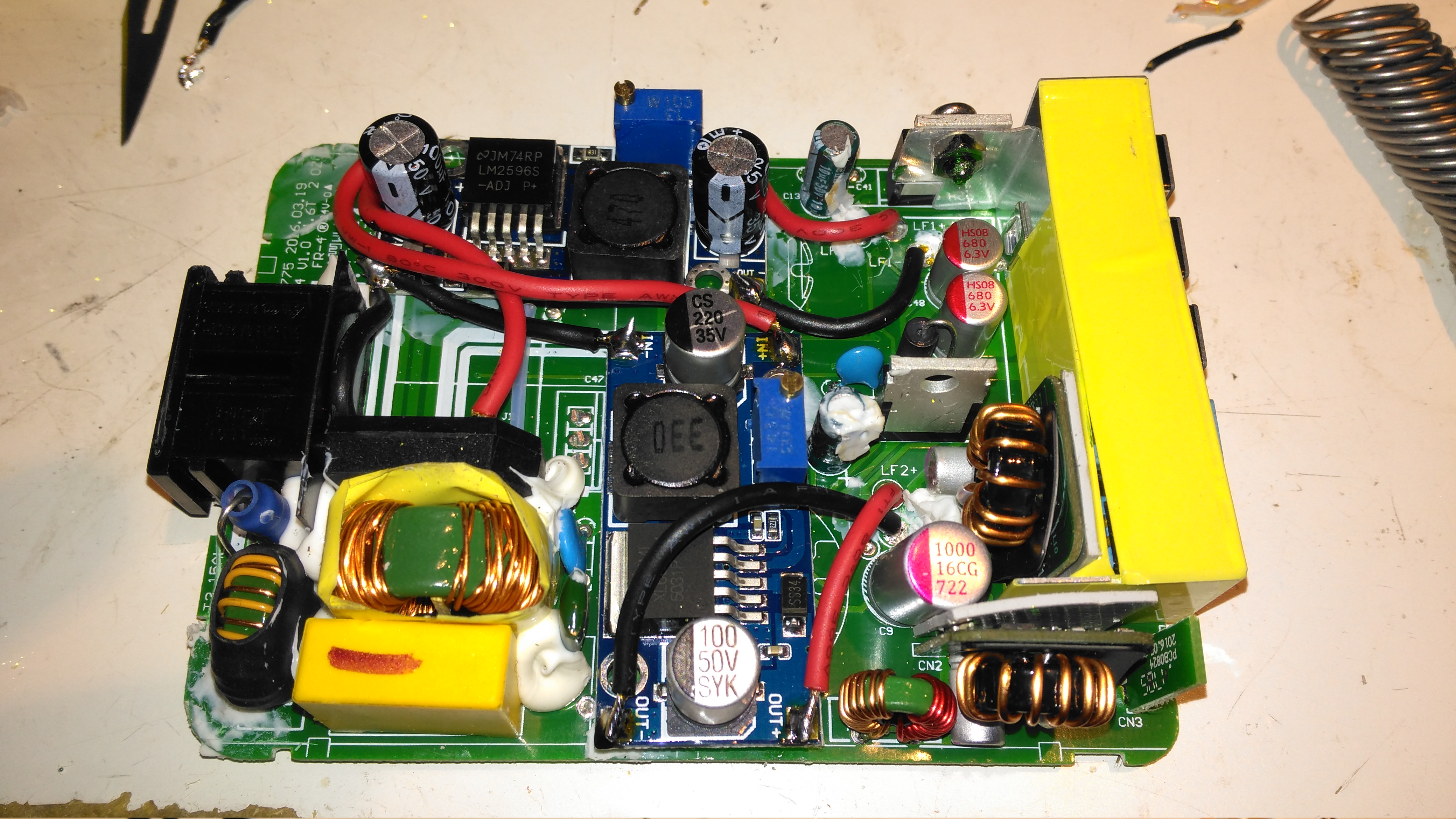
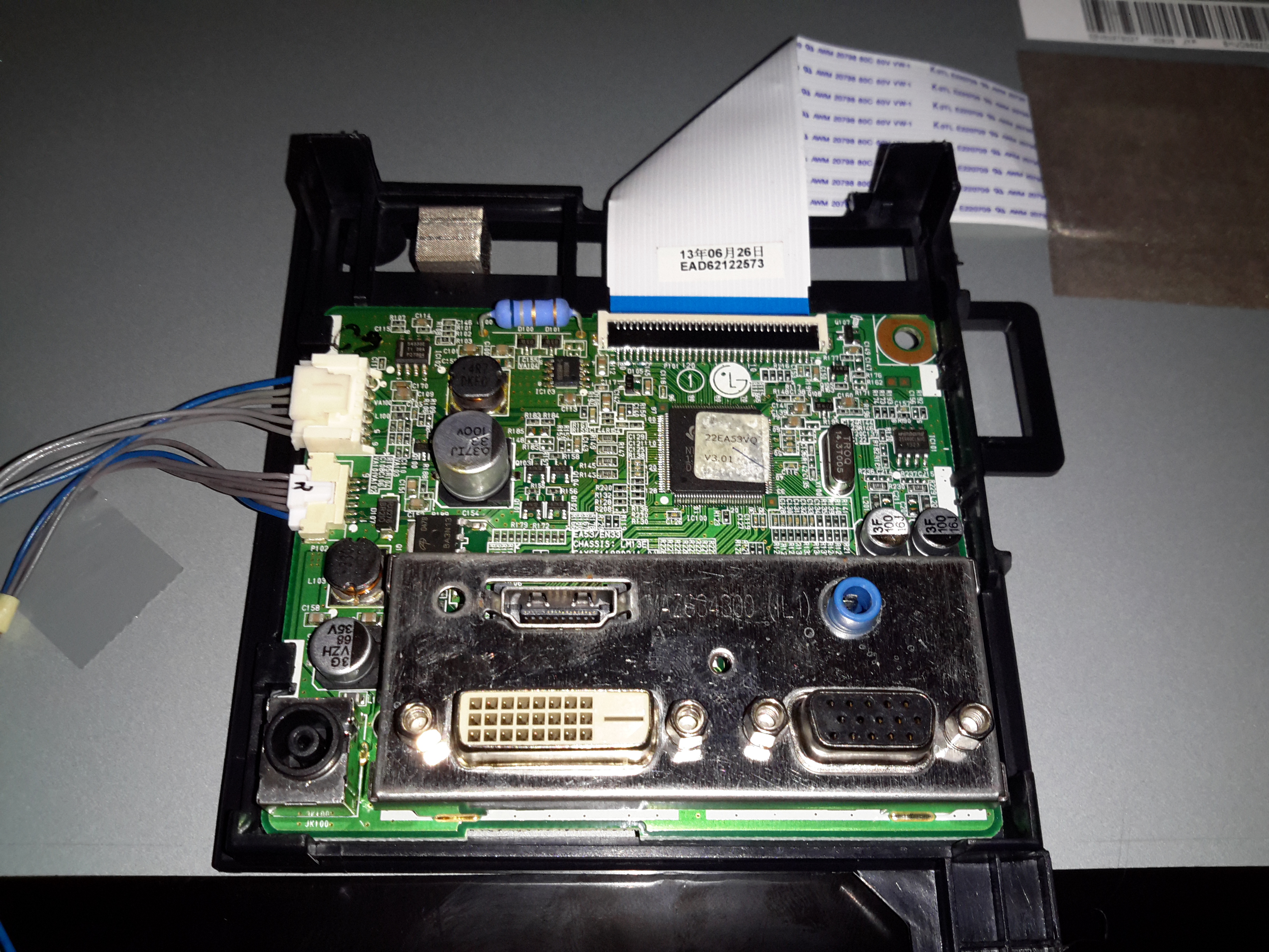
I popped the covers off the monitor itself first, thinking that it was an electrolytic gone bad in the backlight DC-DC converter. Not to mention the fact that cracking into a wall-wart type of PSU is only occasionally possible without the use of anger & large hammers. (Cracking the glue with the handle of a screwdriver doesn’t work so well when the factory went a bit nuts with the glue/ultrasonic welder). As can be seen in the photo, there’s not much inside these monitors, the logic is a single-chip solution, the rest of the PCB is dedicated to supplying the power rails for the various circuits. On the left is the power input & the DC-DC converter for the backlight, along with the DC-DC converter supplying the logic circuits. None of the capacitors here are damaged, everything looks good.
I then measured the output of the PSU, which under no load was the correct 19v DC. However applying any load caused the output voltage to drop like a proverbial brick. Applying a full load of 1.3A saw the output voltage drop so severely that the PSU tripped on it’s UVLO.
200mA Load
At 200mA of load the factory PSU is already dropping to 18v, with a 5.3kHz switching frequency appearing.
500mA Load
At higher load the frequency increases to 11.5kHz & the output voltage has dropped to 11.86v!
750mA Load
750mA was as high as I could make the supply go without it tripping itself out – the UVLO circuit trips at 9v. 12.6kHz is now riding on the severely low DC at this point.
PSU Ratings
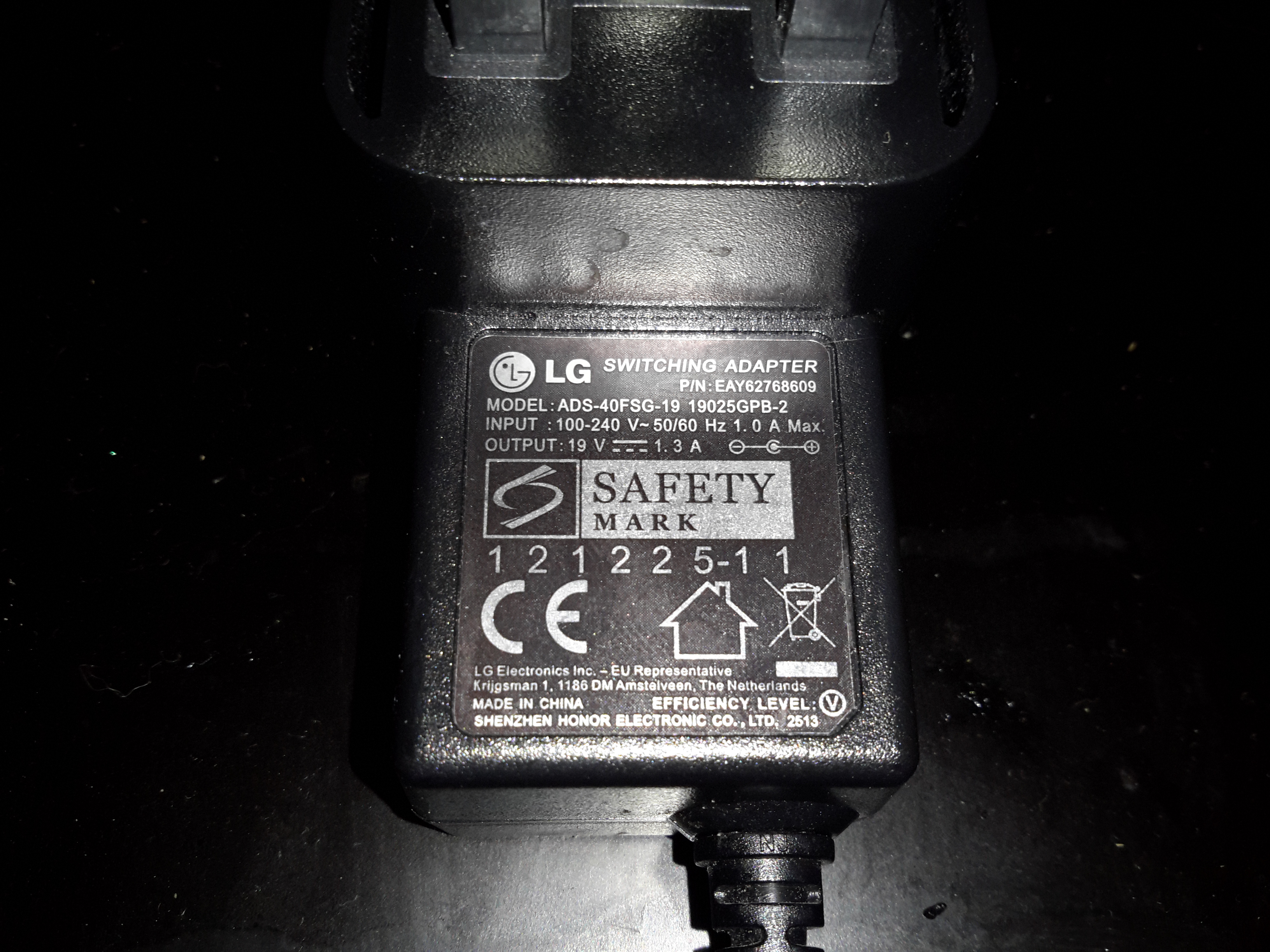
The power supply is supposed to be rated at 1.3A at 19v, however with this fault it’s getting nowhere near that. The LG brand is on this PSU but it’s contracted out to Shenzen Honor Electric Co. Ltd.
Output Electrolytic
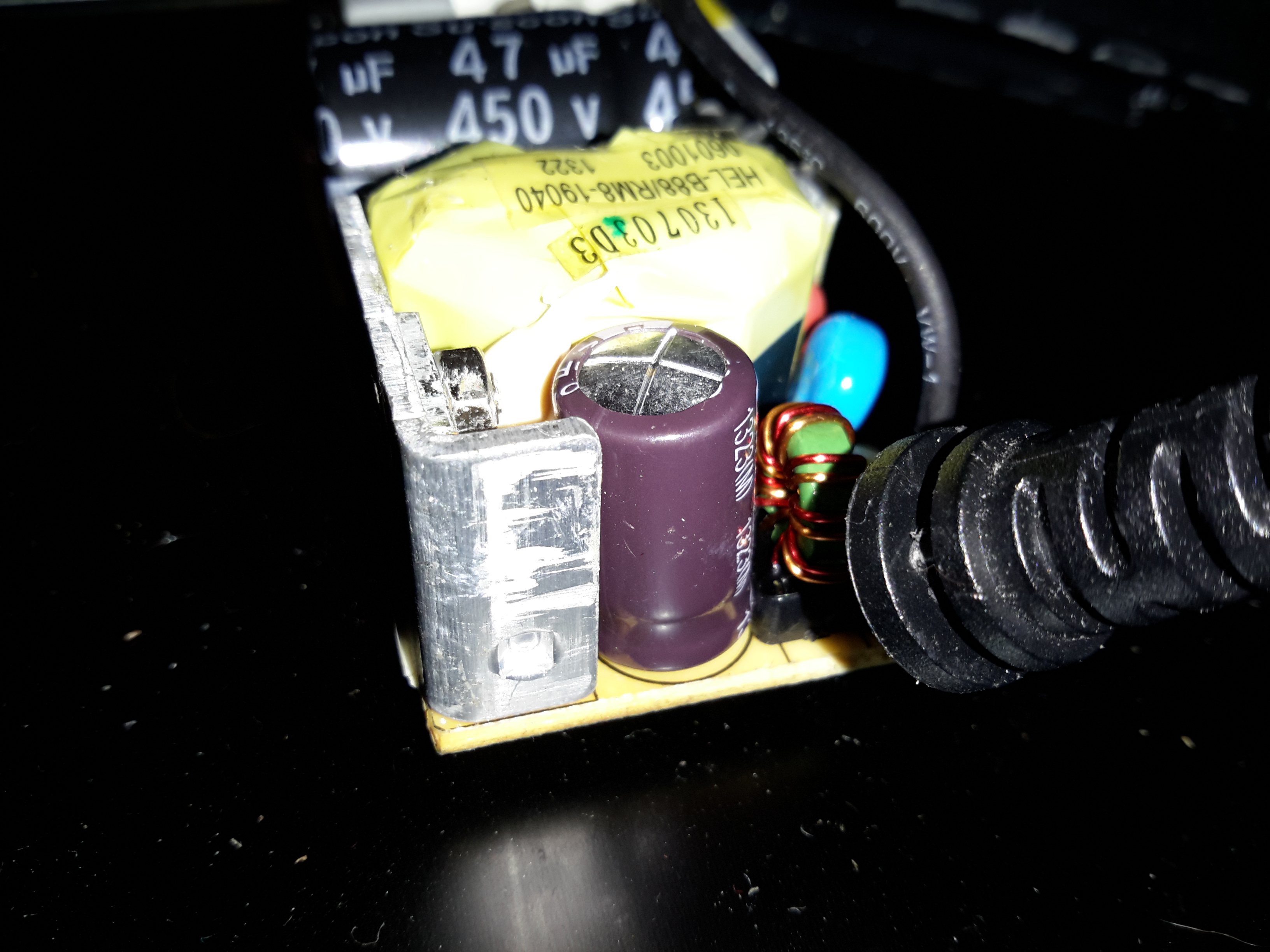
Here’s the problem with this PSU. The output electrolytic has ballooned. I don’t have an ESR tester, but this cap has gone way past it’s sell-by date. It’s position right next to the heatsink with the output rectifier diodes has probably cooked it. The PSU isn’t that badly built for a Chinese one – there’s plenty of creepage distance on the PCB & even a couple of isolation slots.
For a classroom introduction to lasers, it would be nice to have a safe setup that makes as much as possible visible to the students. Or, you may just want to have a working He-Ne laser on display in your living room! Ideally, this is an external mirror laser where all parts of the resonator as well as the power supply can be readily seen. However, realistically, finding one of these is not always that easy or inexpensive, and maintenance and adjustment of such a laser can be a pain (though that in itself IS instructive).
The next best thing is a small He-Ne laser laid bare where its sealed (internal mirror) He-Ne tube, ballast resistors, wiring, and power supply (with exposed circuit board), are mounted inside a clear Plexiglas case with all parts labelled. This would allow the discharge in the He-Ne tube to be clearly visible. The clear insulating case prevents the curious from coming in contact with the high voltage (and line voltage, if the power supply connects directly to the AC line), which could otherwise result in damage to both the person and fragile glass He-Ne tube when a reflex action results in smashing the entire laser to smithereens!
A He-Ne laser is far superior to a cheap laser pointer for several reasons:
The discharge and mirrors are clearly visible permitting the lasing process to be described in detail. Compared to this, a diode laser pointer is about as exciting as a flashlight even if you are able to extract the guts.
The beam quality in terms of coherence length, monochromaticy, shape, and stability, will likely be much higher for the He-Ne laser should you also want to use it for actual optics experiments like interferometry. (However, the first one of these – coherence length – can actually be quite good for even the some of the cheap diode lasers in laser pointers.)
For a given power level, a 632.8nm He-Ne laser will appear about 5 times brighter than a 670 nm laser pointer. 635 nm laser pointers are available but still more expensive. However, inexpensive laser pointers with wavelengths between 650 and 660 nm are becoming increasingly common and have greater relative brightness.
Important: If this see-through laser is intended for use in a classroom, check with your regulatory authority to confirm that a setup which is not explicitly CDRH approved (but with proper laser class safety stickers) will be acceptable for insurance purposes.
For safety with respect to eyeballs and vision, a low power laser – 1 mW or less – is desirable – and quite adequate for demonstration purposes.
The He-Ne laser assembly from a barcode scanner is ideal for this purpose. It is compact, low power, usually runs on low voltage DC (12 V typical), and is easily disassembled to remount in a demonstration case. The only problem is that many of these have fully potted “brick” type power supplies which are pretty boring to look at. However, some have the power supply board coated with a rubbery material which can be removed with a bit of effort (well, OK, a lot of effort!).
He-Ne Tube and Power Supply
For example, this is from a hand-held barcode scanner. A similar unit was separated into its component parts:
Melles Griot He-Ne TubeHe-Ne Laser Power Supply IC-I1
The power supply includes the ballast resistors. These could easily be mounted in a very compact case (as little as 3″ x 6″ x 1″, though spreading things out may improve visibility and reduce make cooling easier) and run from a 12v DC, 1 A wall adapter. Used barcode scanner lasers can often be found for $20 or less.
An alternative is to purchase a 0.5 to 1 mW He-Ne tube and power supply kit. This will be more expensive (figure $5 to $15 for the He-Ne tube, $25 to $50 for the power supply) but will guarantee a circuit board with all parts visible.
The He-Ne tube, power supply, ballast resistors (if separate from the power supply), and any additional components can be mounted with standoffs and/or cable ties to the plastic base. The tube can be separated from the power supply if desired to allow room for labels and such. However, keep the ballast resistors as near to the tube as practical (say, within a couple of inches, moving them if originally part of the power supply board). The resistors may get quite warm during operation so mount them on standoffs away from the plastic. Use wire with insulation rated for a minimum of 10 kV. Holes or slots should be incorporated in the side panels for ventilation – the entire affair will dissipate 5 to 10 Watts or more depending on the size of the He-Ne tube and power supply.
When attaching the He-Ne tube, avoid anything that might stress the mirror mounts. While these are quite sturdy and it is unlikely that any reasonable arrangement could result in permanent damage, even a relatively modest force may result in enough mirror misalignment to noticeably reduce output power. And, don’t forget that the mirror mounts are also the high voltage connections and need to be well insulated from each other and any human contact! The best option is probably to fasten the tube in place using Nylon cable ties, cable clamps, or something similar around the glass portion without touching the mirror mounts at all (except for the power connections).
Provide clearly marked red and black wires (or binding posts) for the low voltage DC or a line cord for AC (as appropriate for the power supply used), power switch, fuse, and power-on indicator. Label the major components and don’t forget the essential CDRH safety sticker (Class II for less than 1 mW or Class IIIa for less than 5 mW).
See:
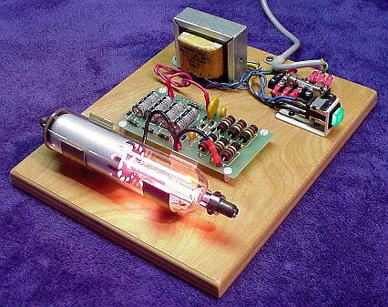
Sam’s Demo He-Ne Laser
Above, as an example (minus the Plexiglas safety cover), contructed from the guts of a surplus Gammex laser (probably part of a patient positioning system for a CT or MRI scanner). The discrete line operated power supply is simple with the HV transformer, rectifier/doubler, filter, multiplier, and ballast resistors easily identified. This would make an ideal teaching aid.
Rather than having a see-through laser that just outputs a laser beam (how boring!), consider something that would allow access to the internal cavity, swapping of optics, and modulation of beam power. OK, perhaps the truly ultimate demo laser would use a two-Brewster tube allowing for interchangeable optics at both ends, be tunable to all the He-Ne spectral lines, and play DVD movies. 🙂 We’ll have to settle for something slightly less ambitious (at least until pigs fly). Such a unit could consist of the following components:
One-Brewster He-Ne laser tube or head. This can be something similar to the Melles Griot 05-LHB-570 tube or the Climet 9048 head which contains this tube. These have a Brewster window at one end and an internal HR mirror with a 60 cm Radius of Curvature (RoC) at the other. Their total length is about 10.5 inches (260 mm).
Adjustable mirror mount with limited range to permit easy mirror tweaking but with minimal chance of getting alignment really messed up. A basic design using a pair of plates with X and Y adjustment screws and a common pivot with lock washers for the compliance springs would be adequate.
Interchangeable mirrors of RoC = 60 cm and reflectance of 98% to 99.5% (OC) and 99.999% (HR in place of OC to maximize internal photon flux). These may be salvaged from a dead 3 to 5 mW He-Ne laser tube. Those from a tube like the Spectra-Physics 084-1 would be suitable. It would be best to install the mirrors in protective cells for ease of handling.
Baseplate to mount the laser and optics with the internal HR of the one-Brewster tube/head about 60 cm from the external mirror to create a confocal cavity – about one half of which is external and accessible. An option would be to put the external mirror mount on a movable slide to allow its position to be changed easily.
Power supply with adjustable current and modulation capability. This would provide the ability to measure output power versus current and to use the laser as an optical transmitter with a solar cell based receiver.
Plexiglas box to house and protect the laser and power supply (as well as inquisitive fingers from high voltage) with part of one side open to allow access to the internal photons.
Everything needed for such a setup is readily available or easily constructed at low cost but you’ll have to read more to find out where or how as each of the components are dealt with in detail elsewhere in Sam’s Laser FAQ (but I won’t tell you exactly where – these are all the hints you get for this one!).
A system like this could conceivably be turned into an interactive exhibit for your local science museum – assuming they care about anything beyond insects and the Internet these days. 🙂 There are some more details in the next section.
Guidelines for a Demonstraton One-Brewster He-Ne Laser
The following suggestions would be for developing a semi-interactive setup whereby visitors can safely (both for the visitor and the laser) adjust mirror alignment and possibly some other parameters of laser operation. The type of one-Brewster (1-B) He-Ne laser tube like the Melles Griot 05-LHB-570. Note that the 05-LHB-570 is a wide bore tube that runs massively multi (transverse) mode with most mirrors configurations unless an intracavity aperture is added. This is actually an advantage for several reasons:
The multi-transverse mode structure is interesting in itself and provides additional options for showing how it can be controlled.
Mirror alignment is easier and the tube will lase over a much wider range of mirror orientation.
Output power is higher for its size and power requirements.
Here are some guidelines for designing an interactive exhibit:
Mount the 1-B tube in a clear plastic (Plexiglas) enclosure with some ventilation holes to allow for cooling but make sure any parts with high voltage (anode, ballast resistors if not insulated) are safely protected from the curious. Provide a small hole lined up with the Brewster window for the intracavity beam. However, even if the B-window is at the cathode-end of the tube, don’t allow it to be accessible as the first fingerprint will prevent lasing entirely.
Put the power supply in a safe place inside another clear plastic box if desired. I’d recommend controlling it with a time switch that will turn it on for perhaps 10 minutes with a push of a button. This is a tradeoff between wear from running the laser all the time and wear from repeated starts. Don’t forget the fuse!!!
Orient the tube so the B-windows is either on the side or facing down. This will minimize dust collection and permit the rig to operate for many hours or days without the need for even dusting.
Use an output mirror with an RoC from 50 cm to planar and reflectivity of 98 to 99.5 percent at 632.8 nm. The specific parameters and distance will affect the beam size, mode structure, and output power. A shorter RoC will limit the distance over which lasing will take place but will be somewhat easier to align.
Use a decent quality mirror mount like a Newport MM-1 for the output mirror. Once it’s secured, arrange for the adjustment screws to be accessible to visitors but limit the range of rotation to less than one turn and mark the location of each screw where lasing is peaked. That way, no amount of fiddling will lose lasing entirely.
The distance between the mirror and tube can be fixed or adjustable:
For a fixed location, a distance of a few inches between the laser enclosure and mirror mount is recommended. This is enough space to install an aperture or Brewster plate. Or a hand to show that the beam is only present with the resonator is complete, not just a red light inside! But, it’s short enough that alignment is still easy.
For added excitement, put the mirror mount on a precision rail to permit the distance to be varied from 0 to at least 45 cm from the B-window. Then, it will be possible to see how the mode structure changes with distance. This will depend on the RoC of the mirror as well.
Another option is to provide various things like an iris diaphragm, thin wires and/or a cross-hair, adjustable knife edge, Brewster plate that can be oriented, etc. However, some care will be needed in making these useful without a lot of hand holding.
Weatherproofing a He-Ne Laser
If you want to use a He-Ne laser outside or where it is damp or very humid, it will likely be necessary to mount the tube and power supply inside a sealed box. Otherwise, stability problems may arise from electrical leakage or the tube may not start at all. There will then be several additional issues to consider:
Heat dissipation – For a small He-Ne tube (say 1 mW), figure this is like a 10 to 15 W bulb inside a plastic box. If you make the box large enough (e.g., 3″ x 5″ x 10″), there should be enough exterior surface area to adequately remove the waste heat.
Getting the beam out – A glass window (e.g., quality microscope slide) mounted at a slight angle (to avoid multiple reflections back to the He-Ne tube output mirror) is best. However, a Plexiglas window may be acceptable (i.e., just pointing the laser at a slight angle through the plastic case). A Brewster angle window should be used only if the He-Ne tube is a linearly polarized type (not likely for something from a barcode scanner) and then the orientation and angle must be set up for maximum light transmission.
Condensation on the optics and elsewhere – This may be a problem on exposed surfaces if they are colder than the ambient conditions. Let the entire laser assembly warm up before attempting to power it up!
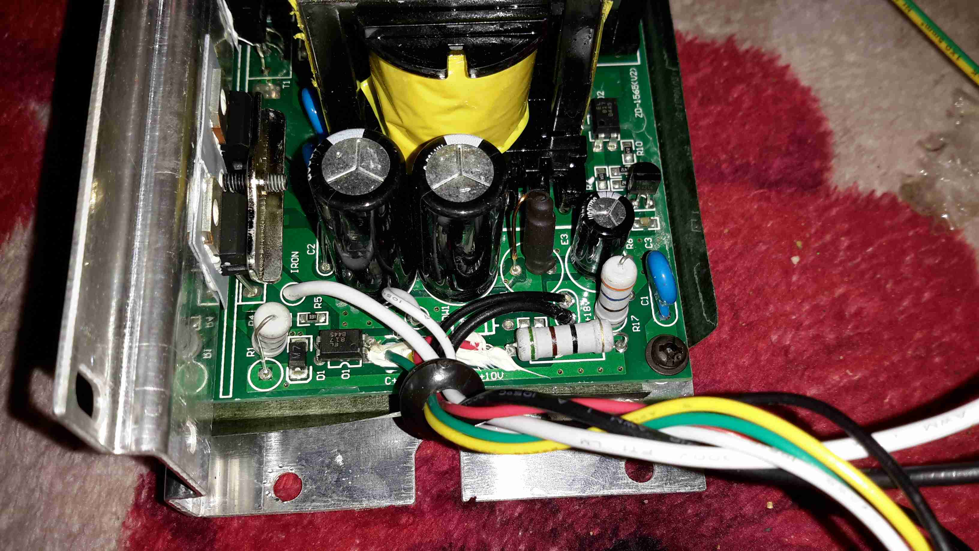
Inkeeping with everything else in my shack being low voltage operated, I had planned from the outset to convert the desoldering station to 12v operation. It turns out this has been the easiest tool to convert in my shack so far.
PSU Outputs
The factory SMPS is a fairly straightforward 18v 12A unit, with only a single small oddity: the desoldering gun’s heating element is controlled from inside the supply.
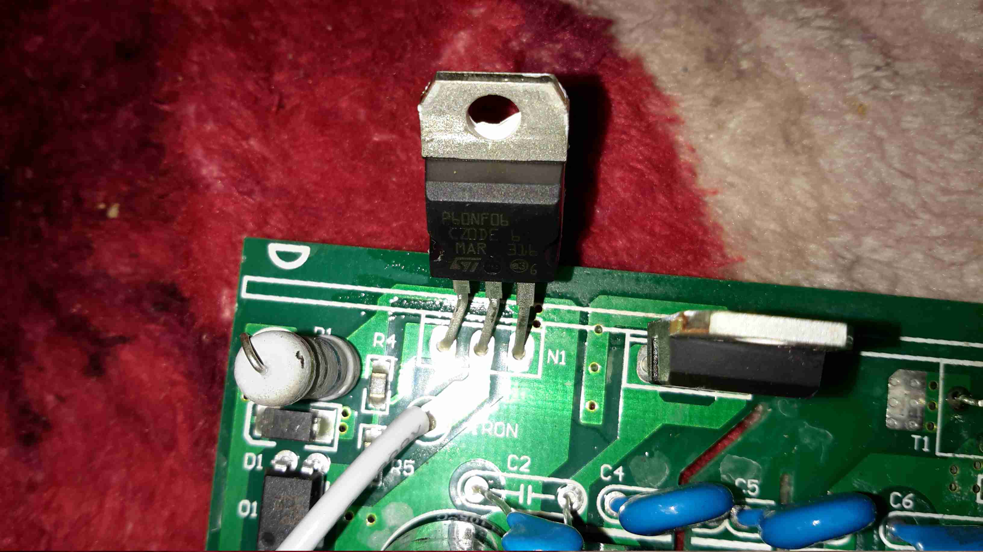
Iron MOSFET
Next to the output rectifier on the heatsink is a large MOSFET, in this case a STP60NF06 from ST Micro. This is a fairly beefy FET at 60v & 60A capacity, RDS On of <0.016Ω.
This is driven via an opto-isolator from the main logic board. I’ve not yet looked at the waveform on the scope, but I suspect this is also being PWM’d to control temperature better when close to the set point.
Iron Element Controller
Rather than fire up the soldering iron & build a new element controller circuit (Lazy Mode™), I opted to take a saw to the original power supply. I cut the DC output section of the PCB off the rest of the supply & attached this piece back to the frame of the base unit. I also added a small heatsink to the MOSFET to make sure it stays cool.
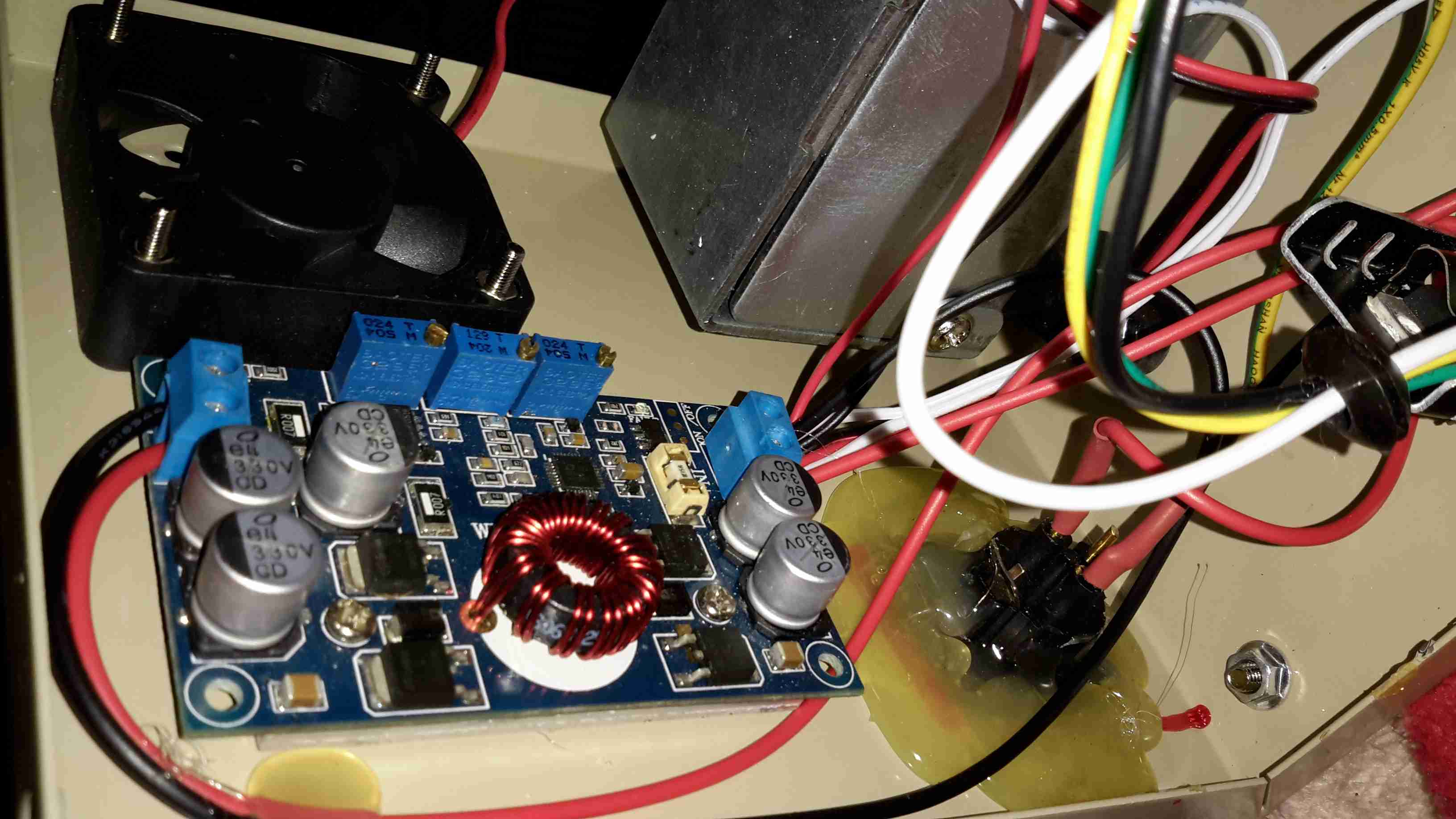
12v Power Supply
Since the fan & vacuum pump are both already 12v rated, those are connected directly to the DC input socket, that I’ve installed in place of the original IEC mains socket. The 18v for the heating element is generated by a 10A DC-DC converter, again from eBay.
Oddly, the iron itself is rated at 24v 80W, but the factory supply is only rated to 18v. I’m not sure why they’ve derated the system, but as the station already draws up to 10A from a 13.8v supply, increasing the voltage any further would start giving my DC supplies a problem, so it can stay at 18v for now.
Now the controllers have arrived, I can rejig the supplies to have proper thermal control on their cooling.
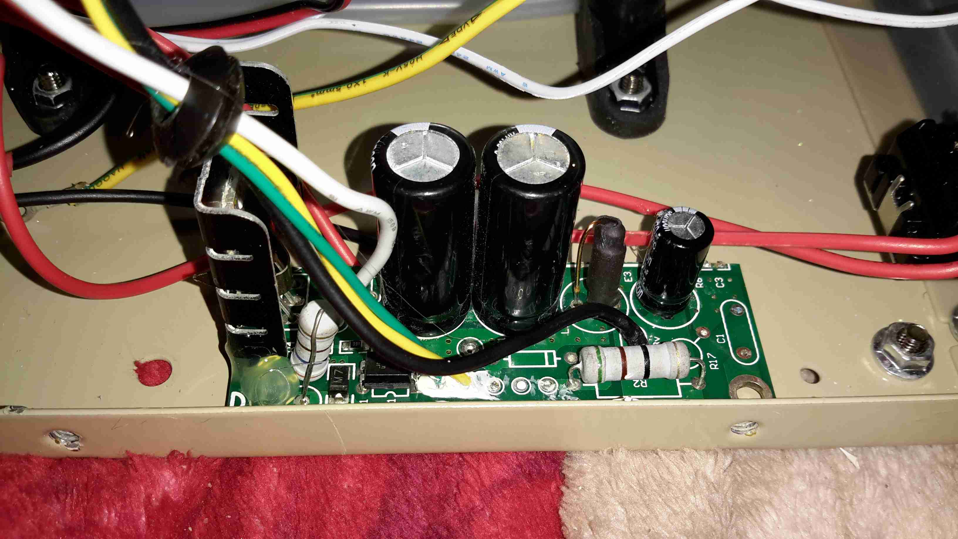
Changes Overview
Here’s the top off the PSU. The board has been added to the back panel, getting it’s 12v supply from the cable that originally fed the fan directly. Luckily there was just enough length on the temperature probe to fit it to the output rectifier heatsink without modification.
To connect to the standard 4-pin headers on the controller, I’ve spliced on a PC fan extension cable, as these fans spent their previous lives in servers, with odd custom connectors.
Fan Controller
Here’s the controller itself, the temperature probe is inserted between the main transformer & the rectifier heatsink.
I’ve set the controller to start accelerating the fan at 50°C, with full speed at 70°C.
Full Load Test
Under a full load test for 1 hour, the fan didn’t even speed up past about 40% of full power. The very high airflow from these fans is doing an excellent job of keeping the supply cool. Previously the entire case was very hot to the touch, now everything is cool & just a hint of warm air exits the vents. As the fan never runs at full speed, the noise isn’t too deafening, and immediately spools back down to minimum power when the load is removed.
The power supplies I have recently built from surplus Cisco switch boards have started displaying a rather irritating problem – continual load of over 9A causes the supplies to shut down on overheat.
This was partially expected, as the original switches that these supplies came from are cooled by a monster of a centrifugal blower that could give a Dyson a run for it’s money. The problem with these fans is that they’re very loud, draw a lot of power (3-4A) and aren’t small enough to fit into the case I’ve used for the project.
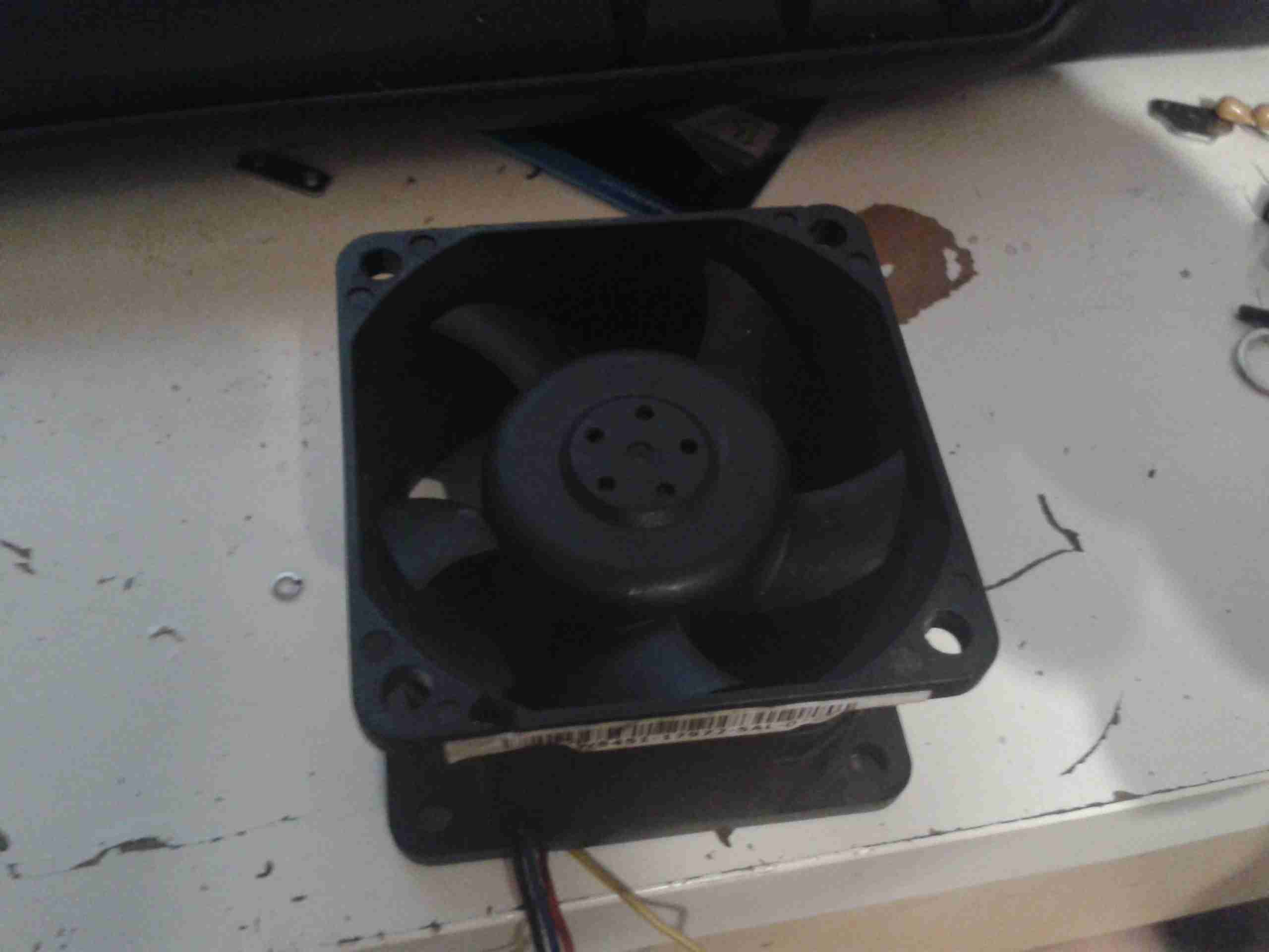
The solution of course, is a bigger fan – I’ve got some Delta AFB0612EHE server fans, these are very powerful axial units, shifting 60CFM at 11,000RPM, with a power draw of 1.12A.
They’re 60mm diameter, so only just fit into the back of the case – although they stick out of the back by 40mm.
Monster Fan
Here’s the fan, not the beefiest I have, but the beefiest that will fit into the available space.
These will easily take fingers off if they get too close at full speed, so guards will definitely be required.
To reduce the noise (they sound like jet engines at full pelt), I have ordered some PWM controllers that have a temperature sensor onboard, so I can have the fan run at a speed proportional to the PSU temperature. I will probably attach the sensor to the output rectifier heatsink, since that’s got the highest thermal load for it’s size.
Since everything in my shack is run from 12v, I thought it would be handy to convert my new scope to 12v as well, as 99% of the places I find myself needing test gear are off grid, with no access to mains supplies.
Mains PSU
Here’s the factory mains SMPS unit from the back of the scope. This is a nice multi-rail unit, with several different outputs, the table below details the wiring of the PSU.
Connector Pin
PCB Pin
Signal
Measured Voltage
Mainboard
Rectifier Rating
Wire Colour
5
1
AC_TRIG
N/A
AC_TRIG
N/A
BROWN
2
2
+9v_GND
N/A
FAN --
NA
ORANGE
11
3
+9V
10.16V
FAN +
2A
WHITE
6
4
+5V
5.1V
5V5A
20A
RED
13
5
+5V
5.1V
5V5A
20A
RED
7
6
GND
N/A
GND
N/A
BLACK
8
7
GND
N/A
GND
N/A
BLACK
3
8
+7.5V
6.9V
6.3V
20A
YELLOW
10
9
+7.5V
6.9V
6.3V
20A
YELLOW
1
10
GND
N/A
GND
N/A
BLACK
12
11
17.5V
17.51V
17.5V
2A
BLUE
9
12
-17.5V
-17.36V
-17.5V
2A
GREY
14
13
GND
N/A
GND
N/A
BLACK
4
14
-7.5V
-6.84V
-7.5V
2A
GREEN
The only feature I will lose if I make this switch is AC line triggering, but I never use that anyway, so it’s not a big issue for me.
Since I have been able to locate the connector, the plan is to design a replacement low voltage supply unit for the scope, with the same footprint as the original AC mains supply. This will allow me to do a direct swap without causing any damage or modifying the original supply.
This method will allow me to swap the 240v supply back into the scope if I ever come to need it.
I’m planning to use the LTC3863 DC-DC Controller from Linear Tech to generate the negative rails, this will go down to -150v on the output, so it’s pretty much perfect to generate them.
PSU Output Side
Here’s the output side of the mains PSU, it has a lot of filtering on the output rails, the two TO220 devices are the output rectifiers for the +5v & +7.5v rails, these are rated at 20A, 60V.
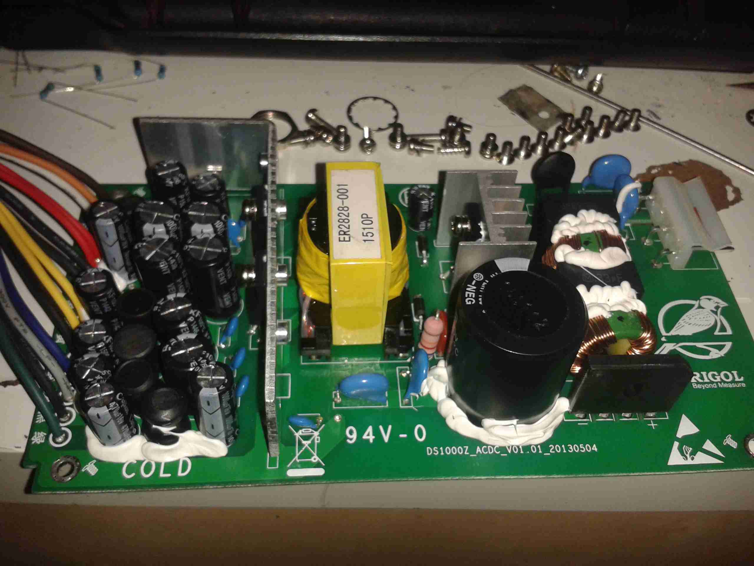
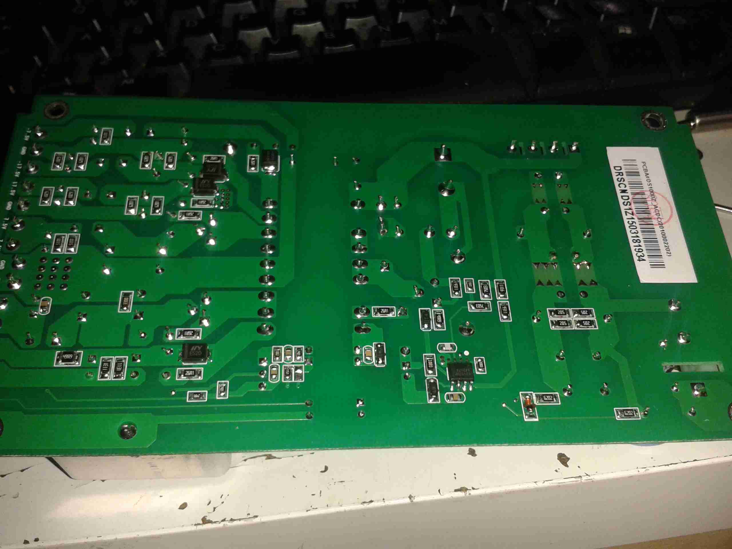
PCB Bottom
Here’s the bottom side of the PCB. It’s a really nicely designed PSU, massive isolation gap, spark gaps on the primary side & good filtering. The output side on the left has the rectifier diodes for the other voltage rails, these are only 2A rated, so designing the inverting supply to generate the negative rails will be pretty easy.
From looking at the PCB markings on both the mainboard & the PSU, the +9v rail seems to be used to drive the fan, both silkscreen markings indicate this.
The voltages marked on the PSU & the mainboard connector don’t quite match up though, there’s a small variation in the stated voltage between the two. This is most likely because all of the regulation of the supplies seems to be done on the mainboard, there are several linear regulators, and a few DC-DC switchers. Providing that the replacement supply isn’t noisy it should work fine.
This is backed up by the fact that the mains PSU only seems to regulate the +5v rail – on measuring the rails that’s the only one that’s close to spec.
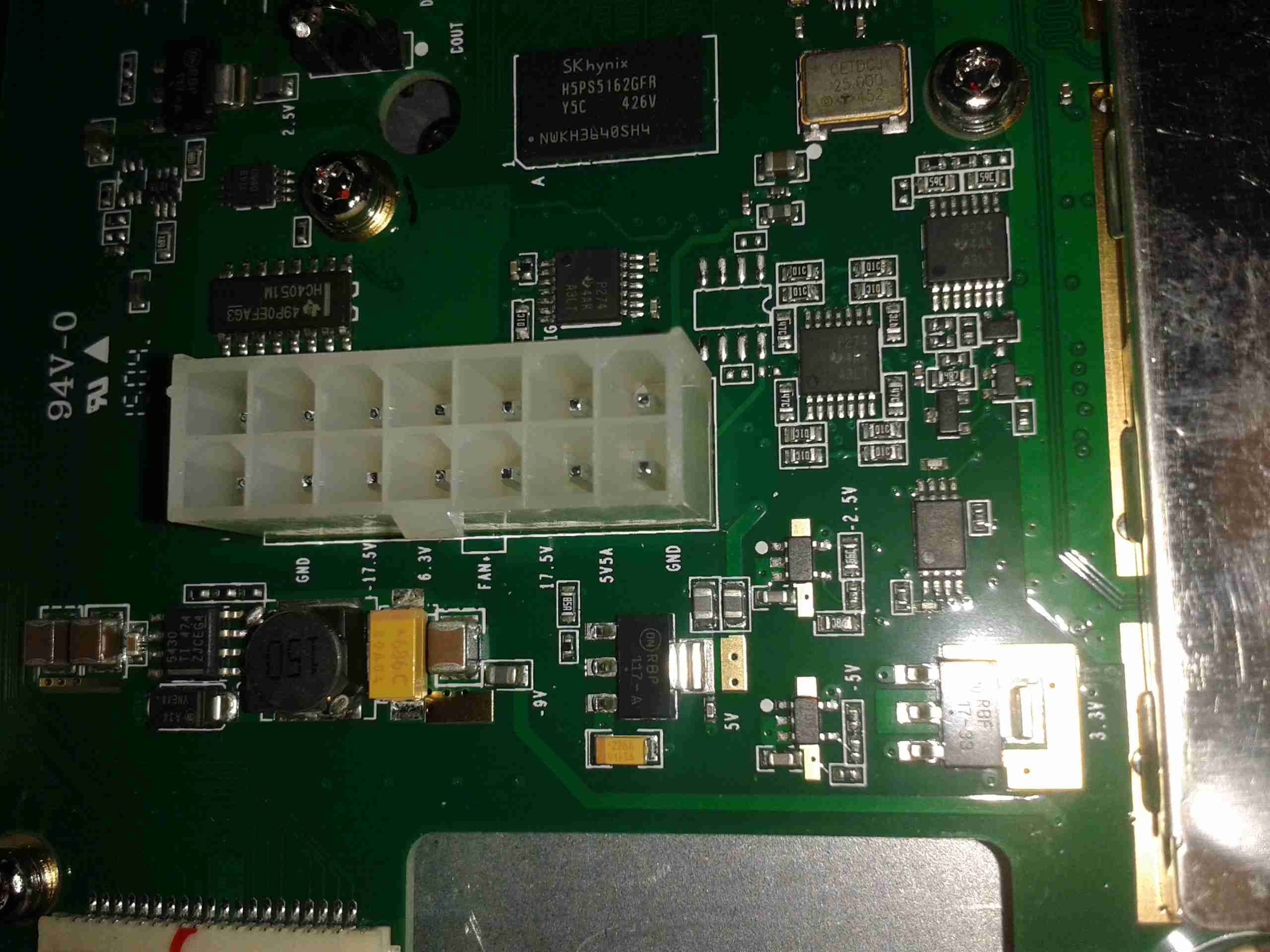
Mainboard Power
Here’s the mainboard power connector, with it’s silkscreen labelling on the pins. (Very useful). As can be seen here, there’s at least 5 regulators, of both switching & linear types here, generating both positive & negative rails.
Recently I decommissioned some networking equipment, and discovered the power supplies in some switches were single rail 12v types, with a rather high power rating. I figured these would be very good for powering my Ham radio gear.
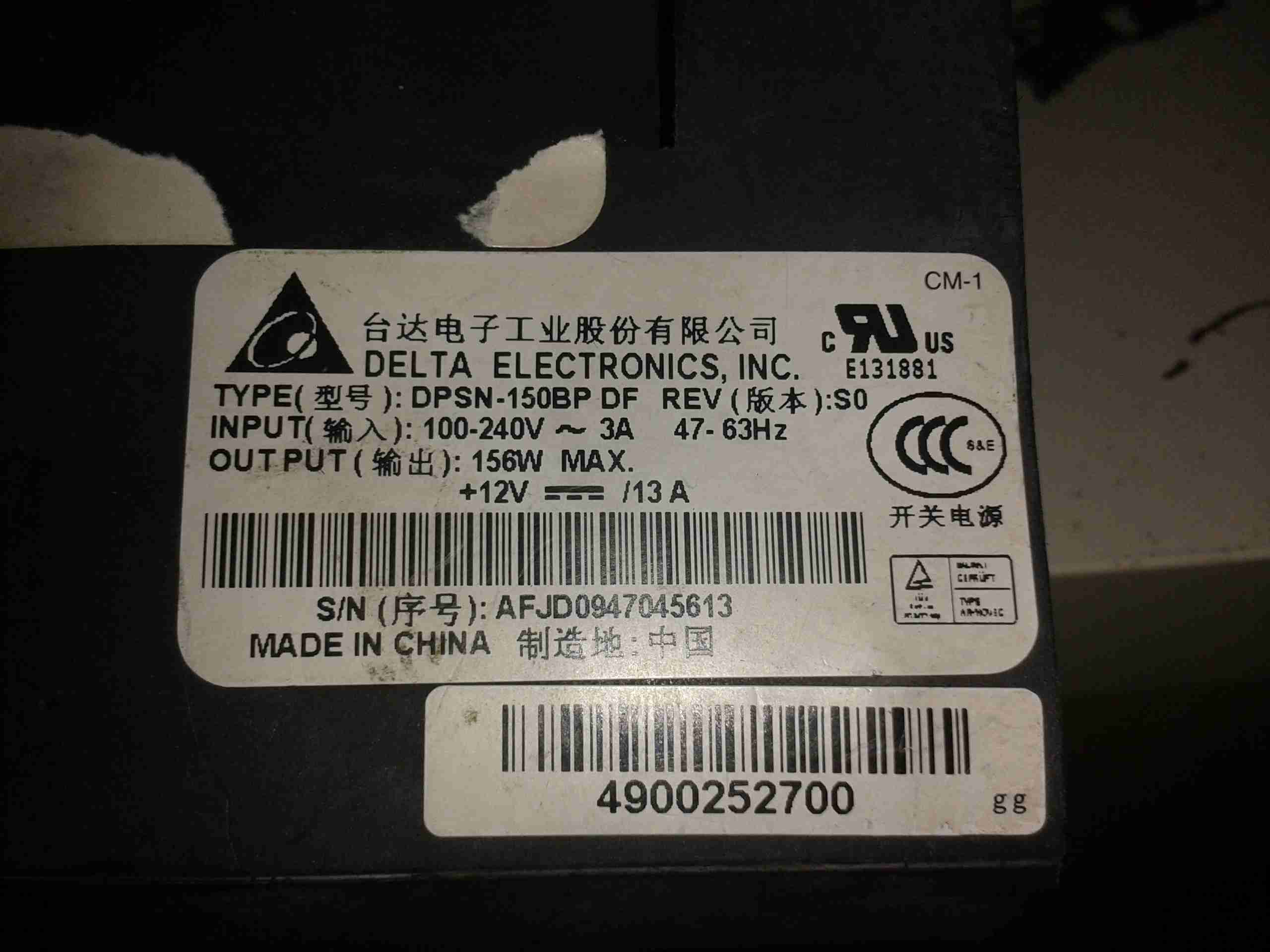
They’re high quality Delta Electronics DPSN-150BP units, rated at a maximum power output of 156W.
Label
These supplies have an adjustment pot for the output voltage regulation, but unfortunately it just didn’t have quite enough range to get from 12.0v to 13.8v. The highest they would go was ~13.04v.
After taking a look at the regulator circuit, I discovered I could further adjust the output voltage by changing a single resistor to a slightly lower value.
Firstly though, a little background on how switched mode power supplies operate & regulate their output voltage.
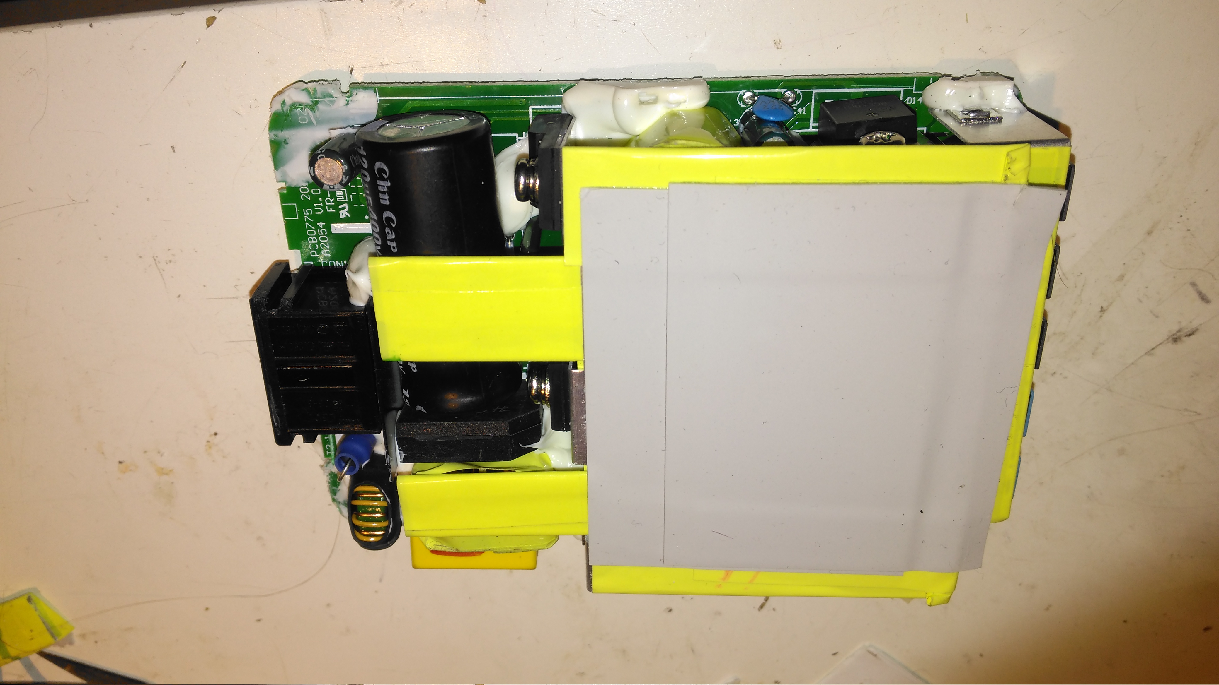
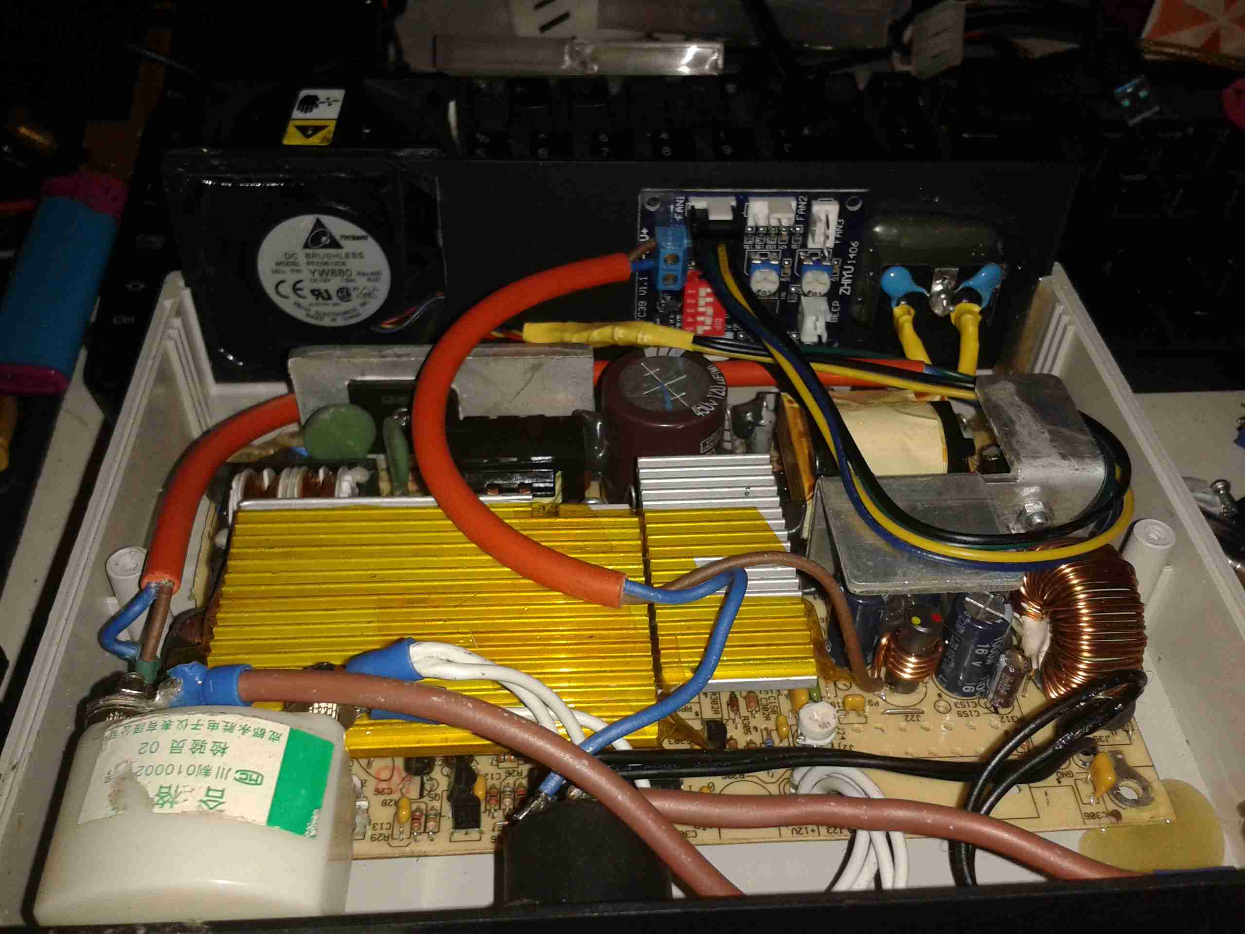
SMPS
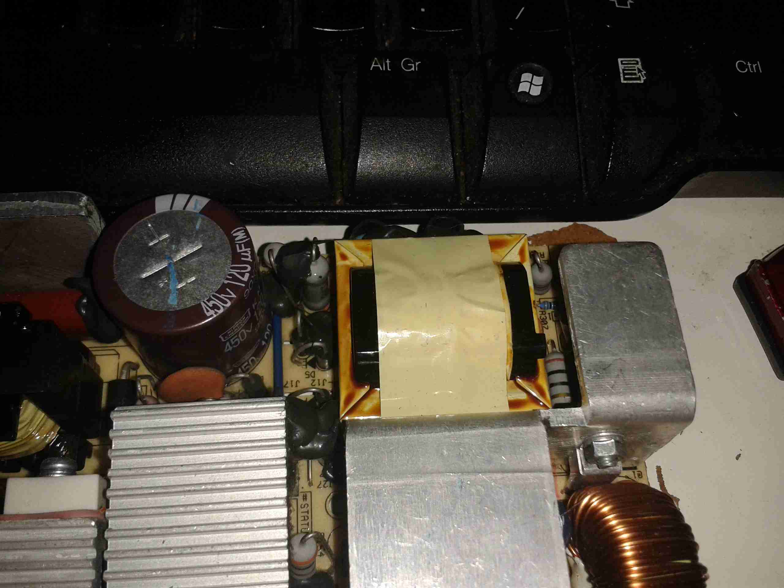
Here’s the supply. It’s mostly heatsink, to cool the large power switching transistors.
The first thing a SMPS does, is to rectify the incoming mains AC with a bridge rectifier. This is then smoothed by a large electrolytic capacitor, to provide a main DC rail of +340v DC (when on a 240v AC supply).
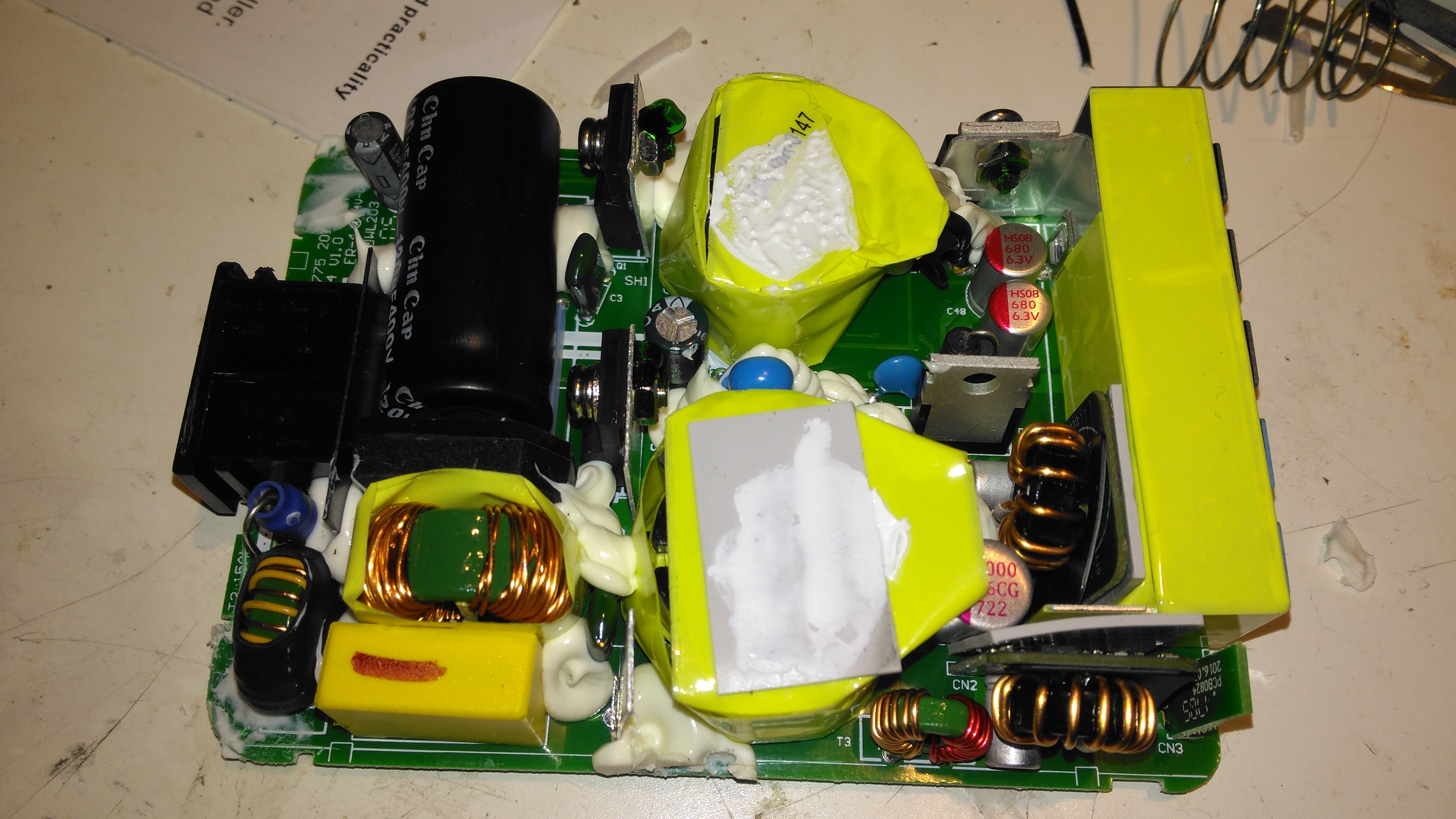
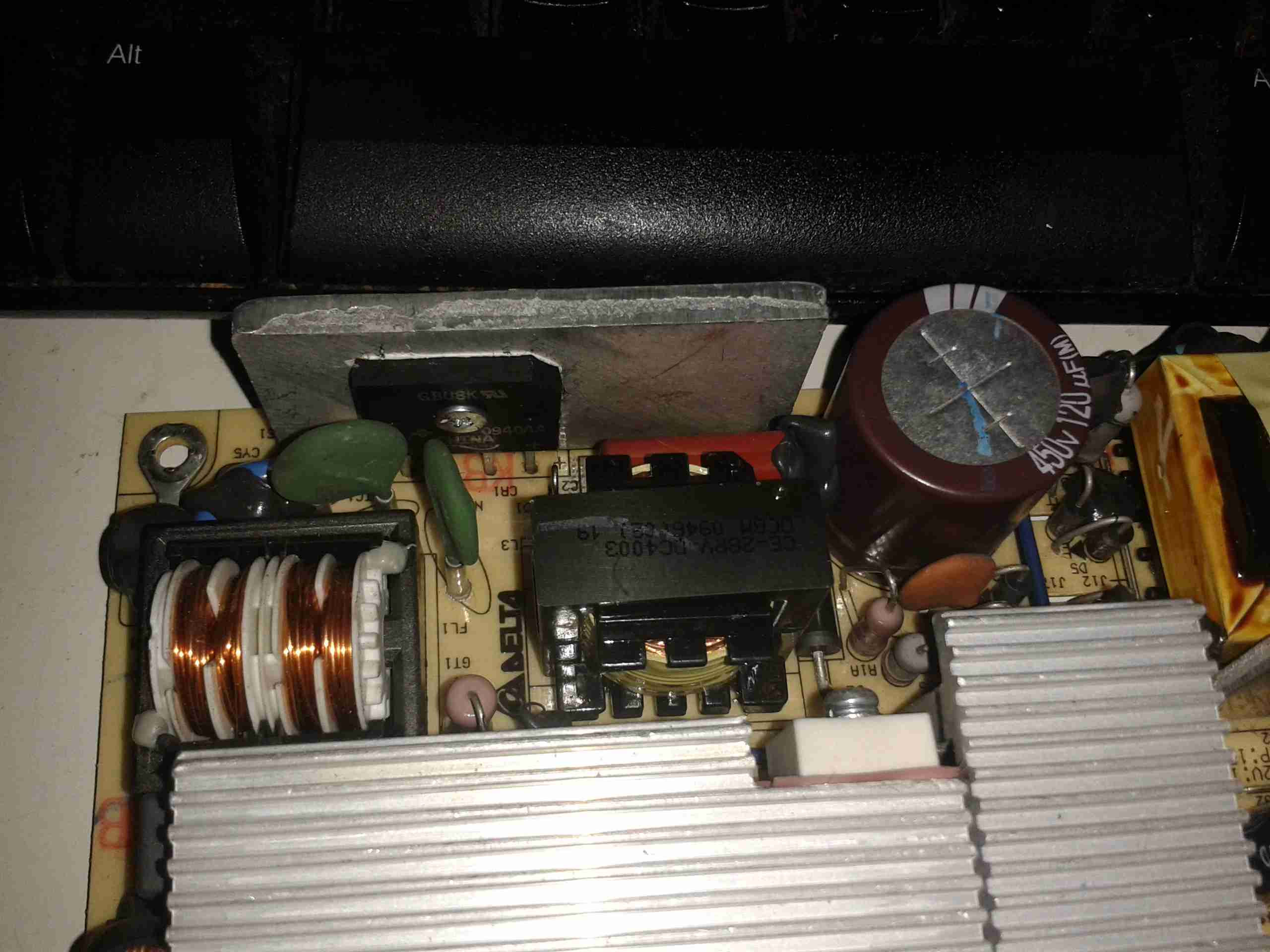
Mains Input
Above is the mains input section of the PSU, with a large common-mode choke on the left, bridge rectifier in the centre, and the large filter capacitor on the right. These can store a lot of energy when disconnected from the mains, and while they should have a discharge resistor fitted to safely drain the stored energy, they aren’t to be relied on for safety!
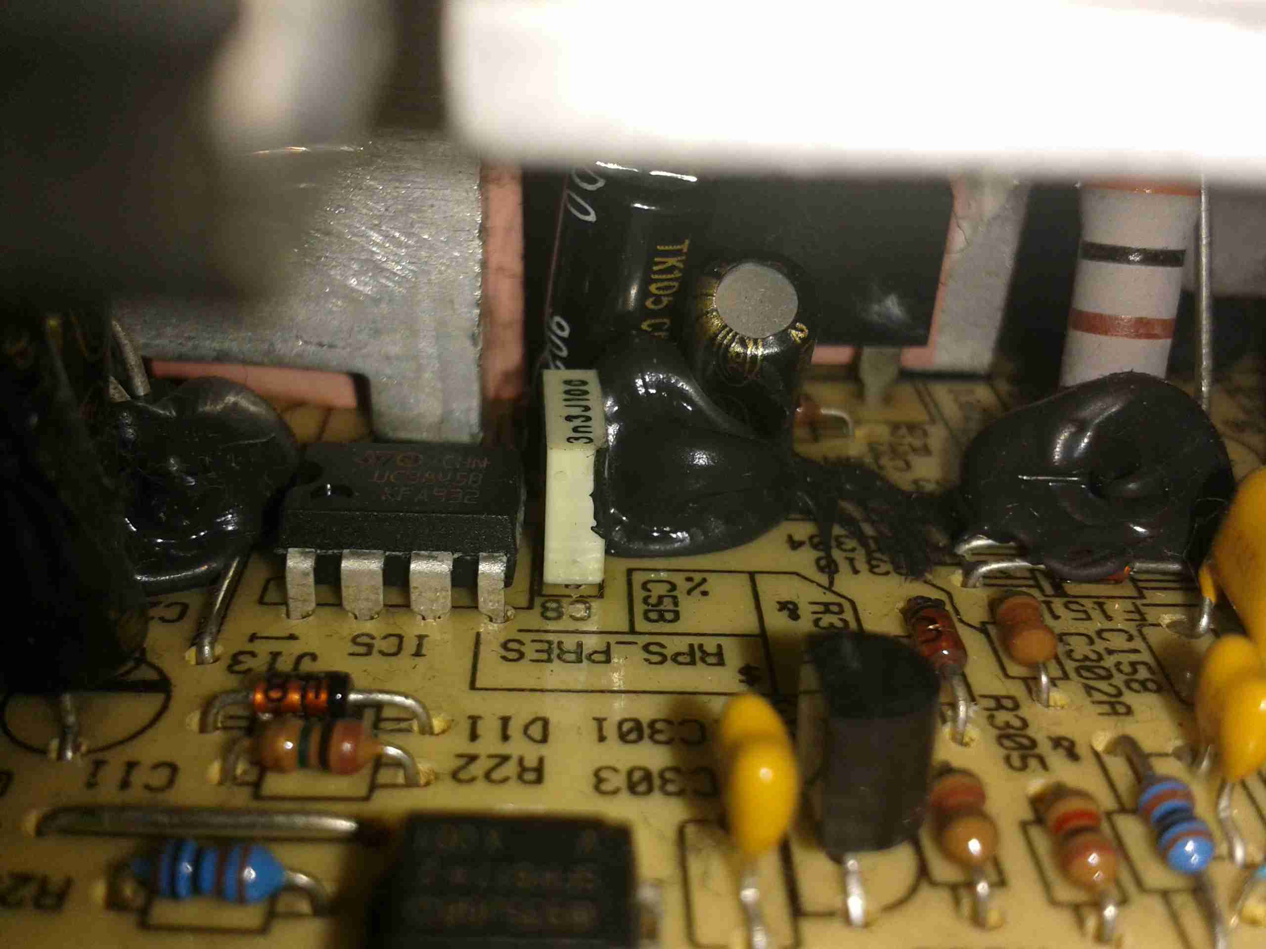
Once the supply has it’s main high voltage DC rail, this is switched into the main transformer by a pair of very large transistors – these are hidden from view on the large silver heatsinks at the bottom of the image. These transistors are themselves driven with a control IC, in the case of this supply, it’s a UC3844B. This IC is hidden under the large heatsink, but is just visible in the below photo. (IC5).
Control ICMain Switching Transformer
Here’s the main switching transformer, these can be much smaller than a conventional transformer due to the high frequencies used. This supply operates at 500kHz.
After the main transformer, the output is rectified by a pair of Schottky diodes, which are attached to the smaller heatsink visible below the transformer, before being fed through a large toroidal inductor & the output filter capacitors.
All this filtering on both the input & the output is required to stop these supplies from radiating their operating frequency as RF – a lot of cheap Chinese switching supplies forego this filtering & as a result are extremely noisy.
After all this filtering the DC appears at the output as usable power.
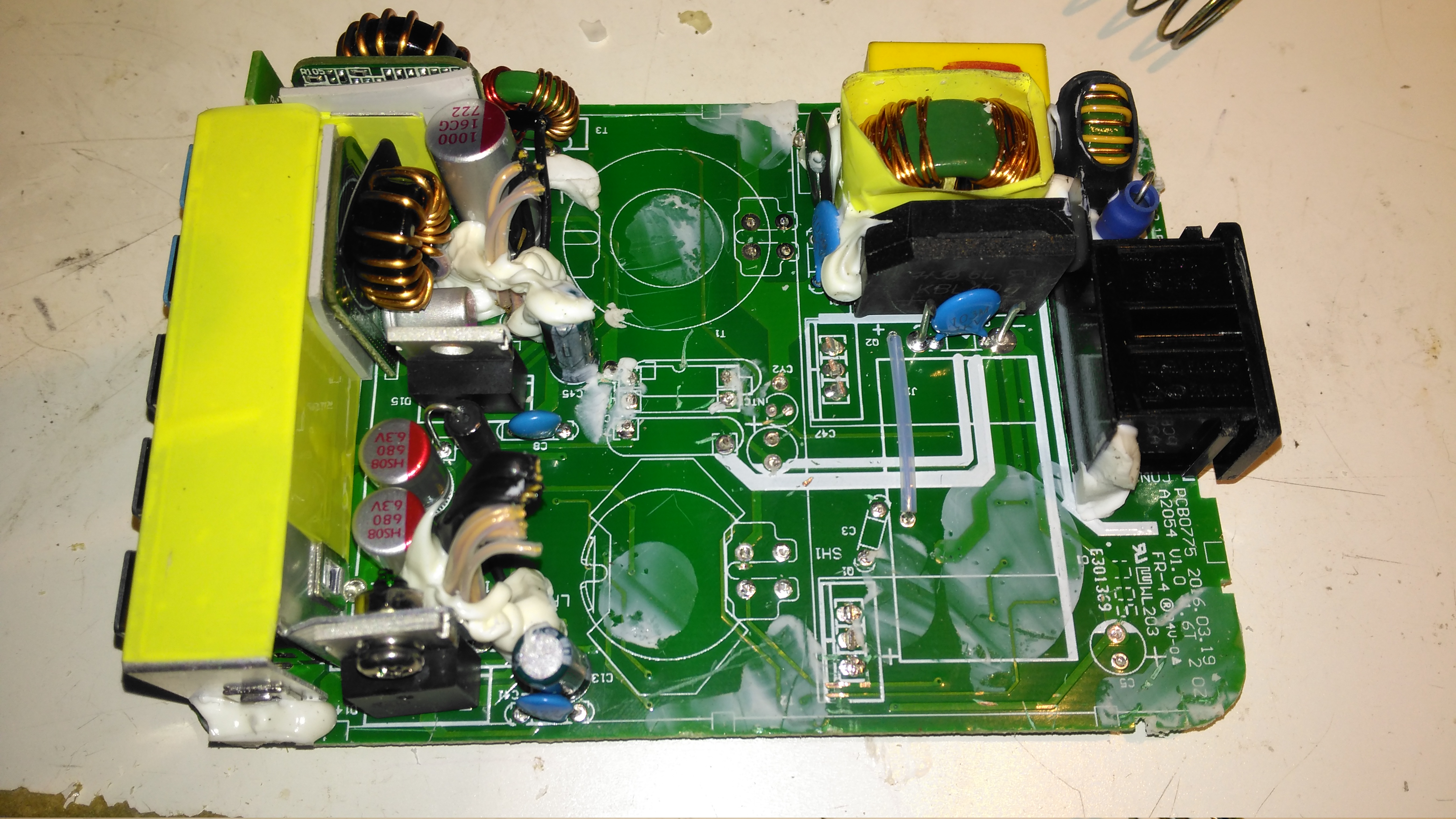
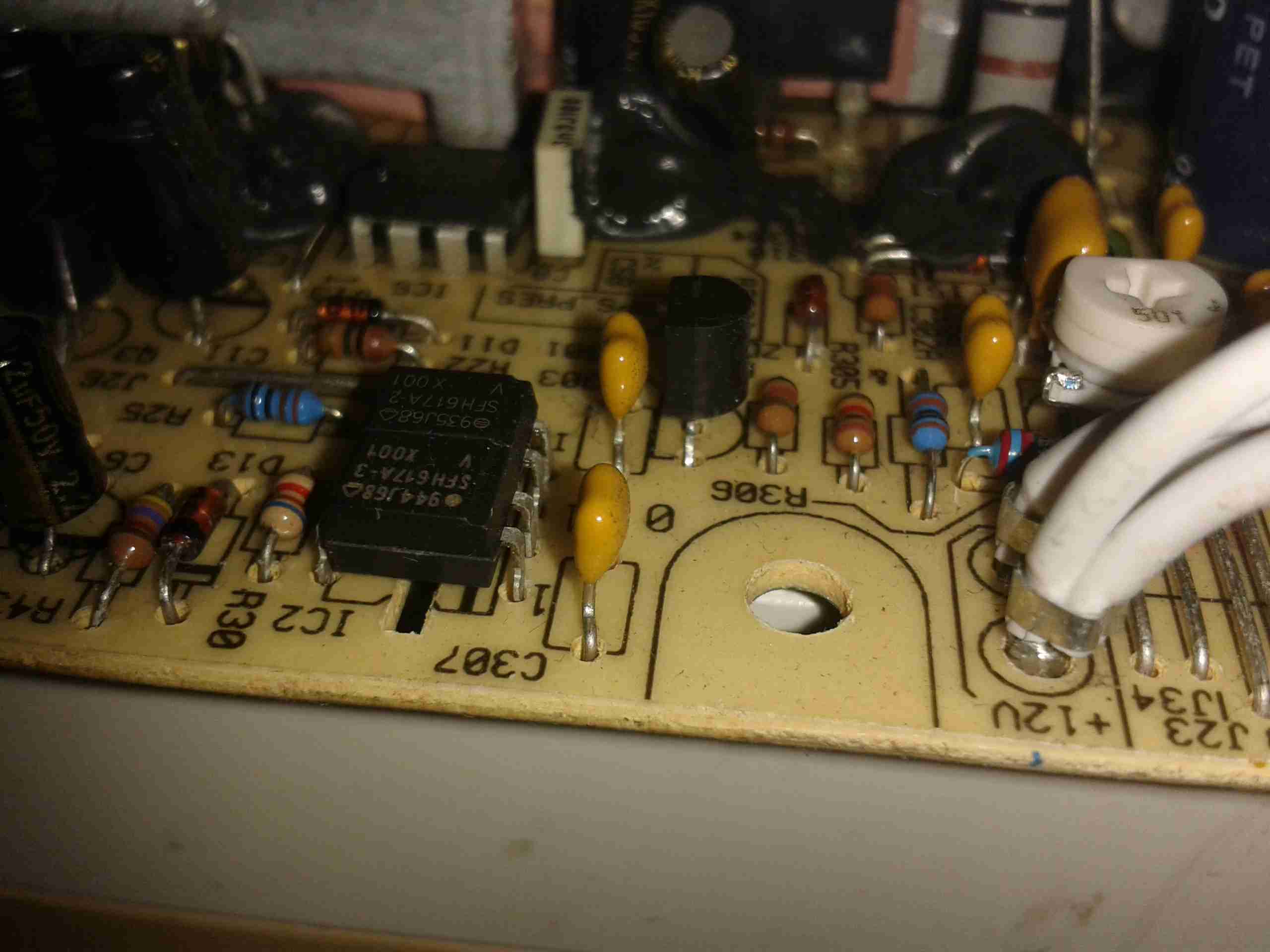
Getting back to regulation, these supplies read the voltage with a resistor divider & feed it back to the mains side control IC, through an opto-isolator. (Below).
Feedback Loop
The opto isolators are the black devices at the front with 4 pins.
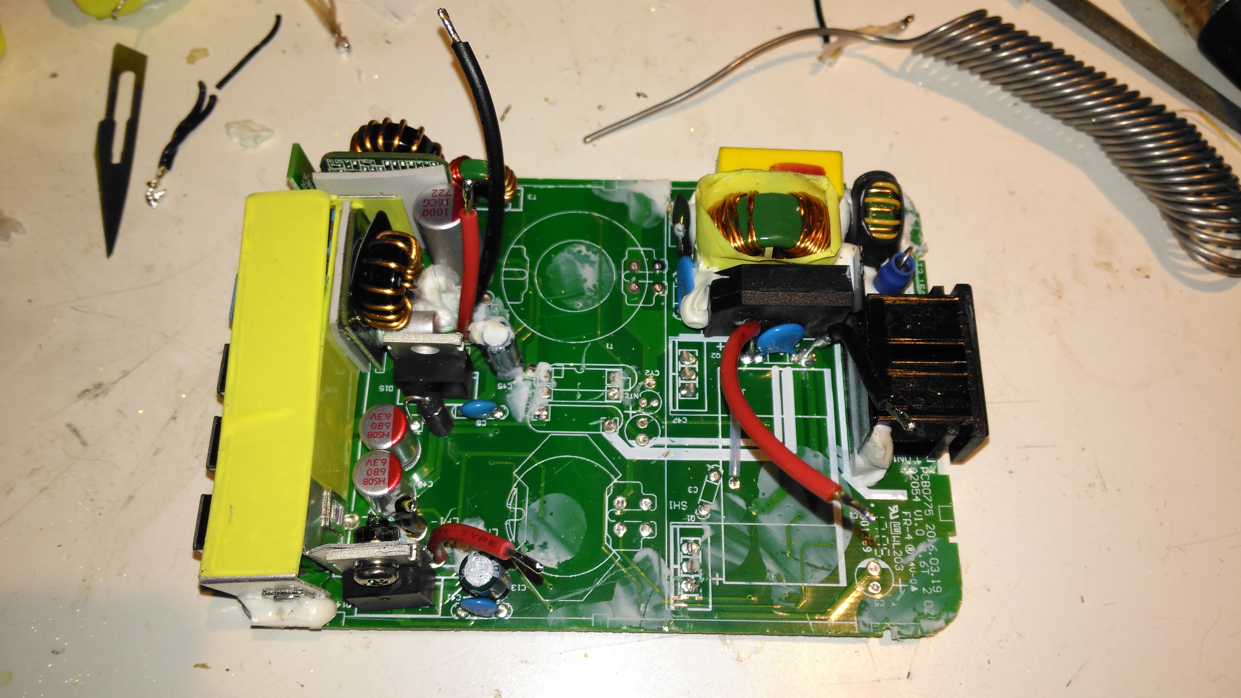
Regulator Adjustment
For a more in-depth look at the inner workings of SMPS units, there’s a good article over on Hardware Secrets.
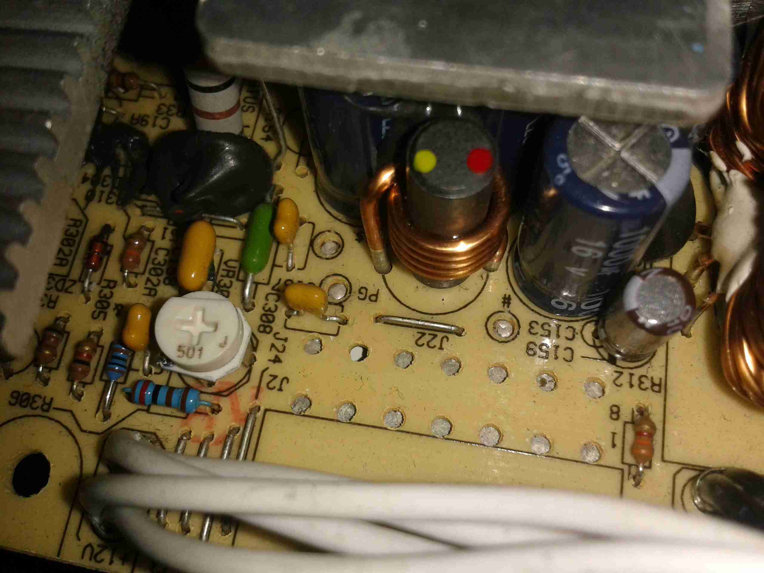
My modification is simple. Replacing R306 (just below the white potentiometer in the photo), with a slightly smaller resistor value, of 2.2KΩ down from 2.37KΩ, allows the voltage to be pulled lower on the regulator. This fools the unit into applying more drive to the main transformer, and the output voltage rises.
It’s important to note that making too drastic a change to these supplies is likely to result in the output filter capacitors turning into grenades due to overvoltage. The very small change in value only allows the voltage to rise to 13.95v max on the adjuster. This is well within the rating of 16v on the output caps.
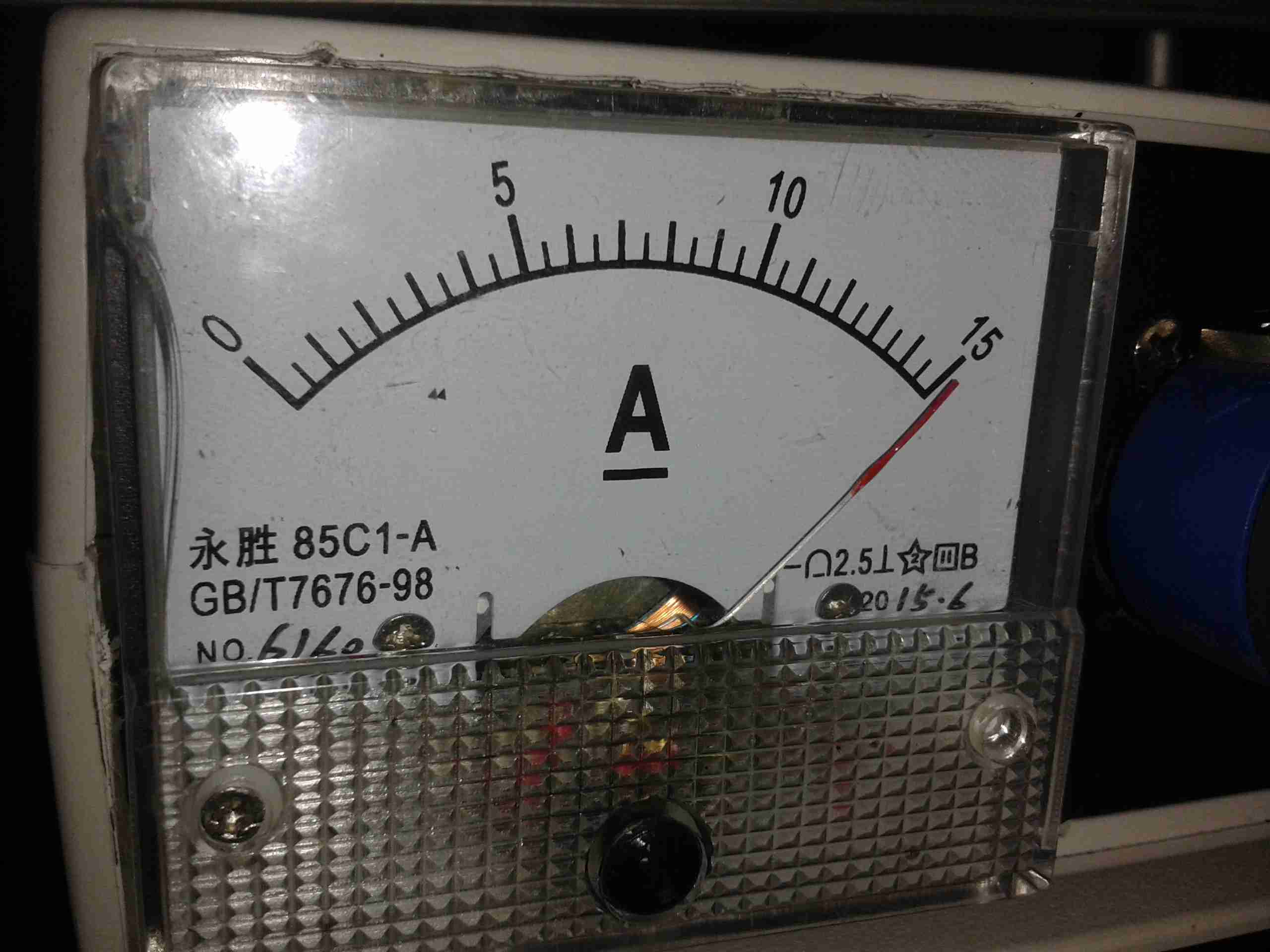
Now the voltage has been sucessfully modified, a new case is on the way to shield fingers from the mains. With the addition of a couple of panel meters & output terminals, these supplies will make great additions to my shack.
A quick post documenting a DPSS laser module i salvaged from a disco scanner. Estimated output ~80mW
Diode Connection
Connection to the 808nm pump diode on the back of the module. There is a protection diode soldered across the diode pins. (Not visible). Note heatsinking of the module.
Driver PCB
Driver PCB. This module was originally 240v AC powered, with a transformer mounted on the PCB with a built in rectifier & filter capacitor. I converted it to 5v operation. Emission LED on PCB.
Here is a cheapo 500W rated ATX PSU that has totally borked itself, probably due to the unit NOT actually being capable of 500W. All 3 of the switching transistors were shorted, causing the ensuing carnage:
AC Input
Here is the AC input to the PCB. Note the vapourised element inside the input fuse on the left. There is no PFC/filtering built into this supply, being as cheap as it is links have been installed in place of the RFI chokes.
Input Side
Main filter capacitors & bridge rectifier diodes. PCB shows signs of excessive heating.
Filter Caps Removed
Filter capacitors have been removed from the PCB here, showing some cooked components. Resistor & diode next to the heatsink are the in the biasing network for the main switching transistors.
Heatsinks Removed
Heatsink has been removed, note the remaining pin from one of the switching transistors still attached to the PCB & not the transistor 🙂
Transformers
Output side of the PSU, with heatsink removed. Main transformer on the right, transformers centre & left are the 5vSB transformer & feedback transformer.
Output Side
Output side of the unit, filter capacitors, choke & rectifier diodes are visible here attached to their heatsink.
Comparator
Comparator IC that deals with regulation of the outputs & overvoltage protection.
This is an old cordless landline phone, with dead handset batteries.
Handset Radio Board
Here’s the handset with the back removed. Shown is the radio TX/RX board, underneath is the keyboard PCB with the speaker & mic. All the FM radio tuning coils are visible & a LT450GW electromechanical filter.
Handset Radio Board Bottom
Radio PCB removed from the housing showing the main CPU controlling the unit, a Motorola MC13109FB.
Keypad Board
The keypad PCB, with also holds the microphone & speaker.
Handset Keypad Board Bottom
Bottom of the keypad board, which holds a LSC526534DW 8-Bit µC & a AT93C46R serial EEPROM for phone number storage.
Base Main Board
Here’s the base unit with it’s top cover removed. Black square object on far right of image is the microphone for intercom use, power supply section is top left, phone interface bottom left, FM radio is centre. Battery snap for power backup is bottom right.
Power Supply Section
PSU section of the board on the left here, 9v AC input socket at the bottom, with bridge rectifier diodes & main filter capacitor above. Two green transformers on the right are for audio impedance matching. Another LT450GW filter is visible at the top, part of the base unit FM transceiver.
ICs
Another 8-bit µC, this time a LSC526535P, paired with another AT93C46 EEPROM. Blue blob is 3.58MHz crystal resonator for the MCU clock. The SEC IC is a KS58015 4-bit binary to DTMF dialer IC. This is controlled by the µC.
Base Main Board Bottom
Underside of the base unit Main PCB, showing the matching MC13109FB IC for the radio functions.
Here is a Bosch 14.4v Professional cordless drill/driver, recovered from a skip!
It was thrown away due to a gearbox fault, which was easy to rectify.
Internals
Here is the drill with the side cover removed, showing it’s internal parts. The speed controller is below the motor & gearbox here. The unit at the top consists of a 12v DC motor, coupled to a 4-stage epicyclic gearbox unit, from which can be selected 2 different ratios, by way of the lever in the centre of the box. This disables one of the gear stages. There is a torque control clutch at the chuck end of the gearbox, this was faulty when found.
Motor
Here is the drive motor disconnected from the gearbox, having a bayonet fitting on the drive end.
Drive Gear
This is the primary drive gear of the motor, which connects with the gearbox.
Cooling Fan
The motor is cooled by this fan inside next to the commutator, drawing air over the windings.
Gearbox
This is the gearbox partially disassembled, showing the 1st & second stages of the geartrain. The second stage provides the 2 different drive ratios by having the annulus slide over the entire gearset, disabling it entirely, in high gear. The annulus gears are a potential weak point in this gearbox, as they are made from plastic, with all other gears being made of steel.
Charger
Here is the charging unit for the Ni-Cd battery packs supplied with the drill. The only indicator is the LED shown here on the front of the unit, which flashes while charging, & comes on solid when charging is complete. Charge termination is by way of temperature monitoring.
Transformer
Here the bottom of the charger has been removed, showing the internal parts. An 18v transformer supplies power to the charger PCB on the left.
Charger PCB
This is the charger PCB, with a ST Microelectronics controller IC marked 6HKB07501758. I cannot find any information about this chip.
Battery Pack Internals
Here is a battery pack with the top removed, showing the cells.
Temperature Sensor
This is the temperature sensor embedded inside the battery pack that is used by the charger to determine when charging is complete.
This is a 1500W hairdryer, death caused by thermal switch failure.
Switch
This is the switch unit. Attached are two suppression capacitors & a blocking diode. Cold switch is on right.
Heating Element
Heating element unit removed from housing. Coils of Nichrome wire heat the air passing through the dryer. Fan unit is on right.
Thermal Switch
Other side of the heating element unit, here can be seen the thermal switch behind the element winding. (Black square object).
Fan Motor
The fan motor in this dryer is a low voltage DC unit, powered through a resistor formed by part of the heating element to drop the voltage to around 12-24v. Mounted on the back of the motor here is a rectifier assembly. Guide vanes are visible around the motor, to straighten the airflow from the fan blades.
Fan
5-blade fan forces air through the element at high speed. Designed to rotate at around 13,000RPM.
Tip Jar
If you’ve found my content useful, please consider leaving a donation by clicking the Tip Jar below!
All collected funds go towards new content & the costs of keeping the server online.