Posted on 12 Comments

Zhiyu ZBP30A1 Electronic Dummy Load

60W DC Electronic Load

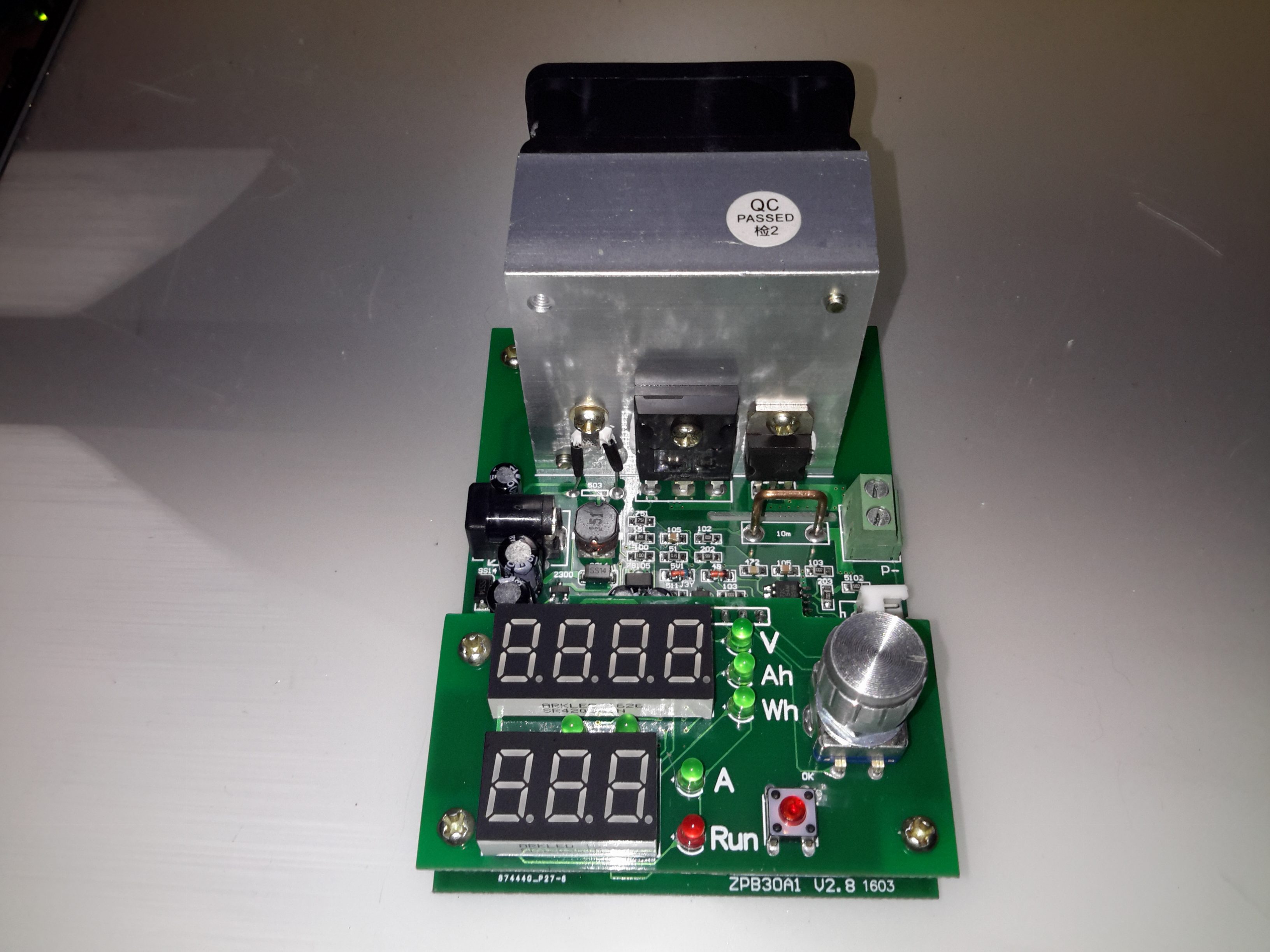
Here’s a useful tool for testing both power supplies & batteries, a dummy load. This unit is rated up to 60W, at voltages from 1v to 25v, current from 200mA to 9.99A.
This device requires a 12v DC power source separate from the load itself, to power the logic circuitry.

Microcontroller Section

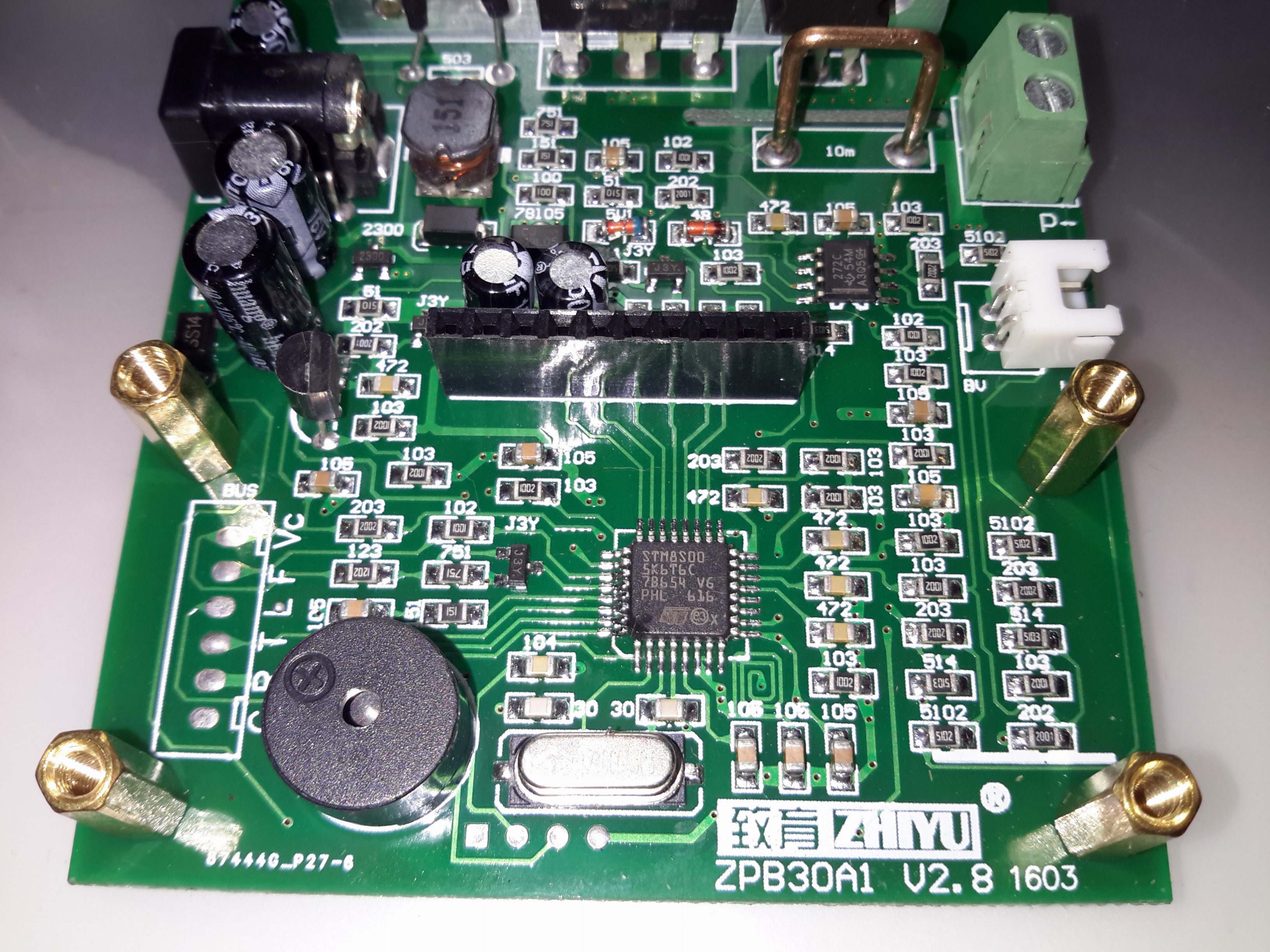
Like many of these modules, the brains of the operation is an STM8 microcontroller. There’s a header to the left with some communication pins, the T pin transmits the voltage when the unit is operating, along with the status via RS232 115200 8N1. This serial signal is only present in DC load mode, the pin is pulled low in battery test mode. The 4 pins underneath the clock crystal are the programming pins for the STM8.

Serial Comms
Serial Comms
Cooling Fan
Cooling Fan

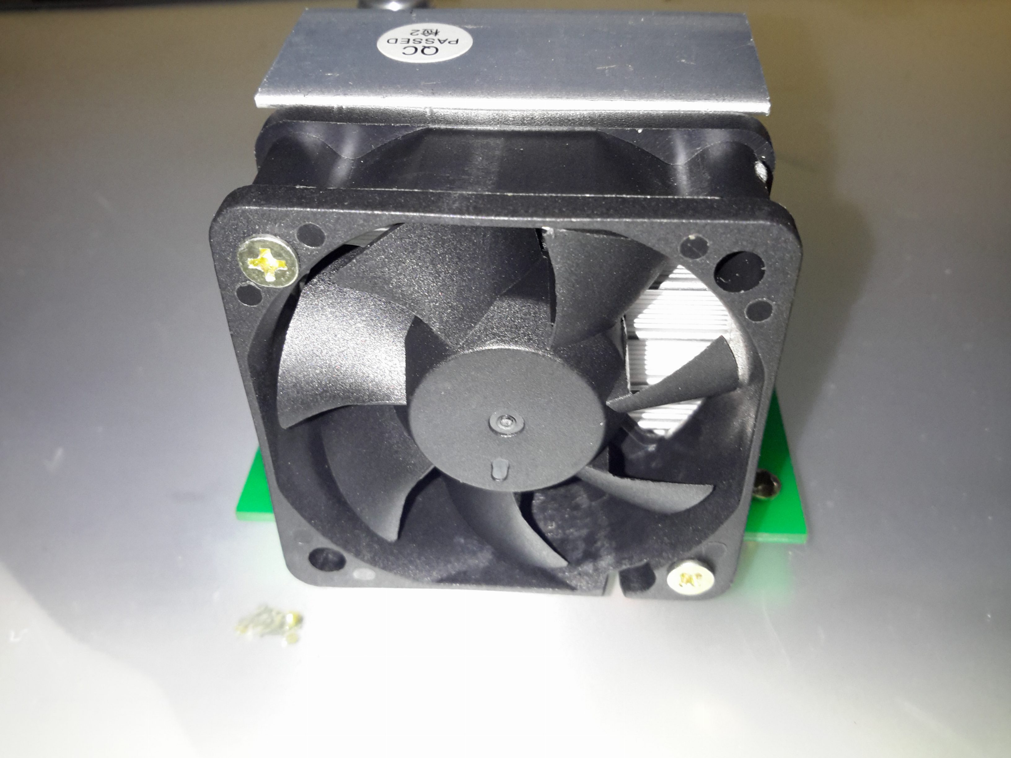
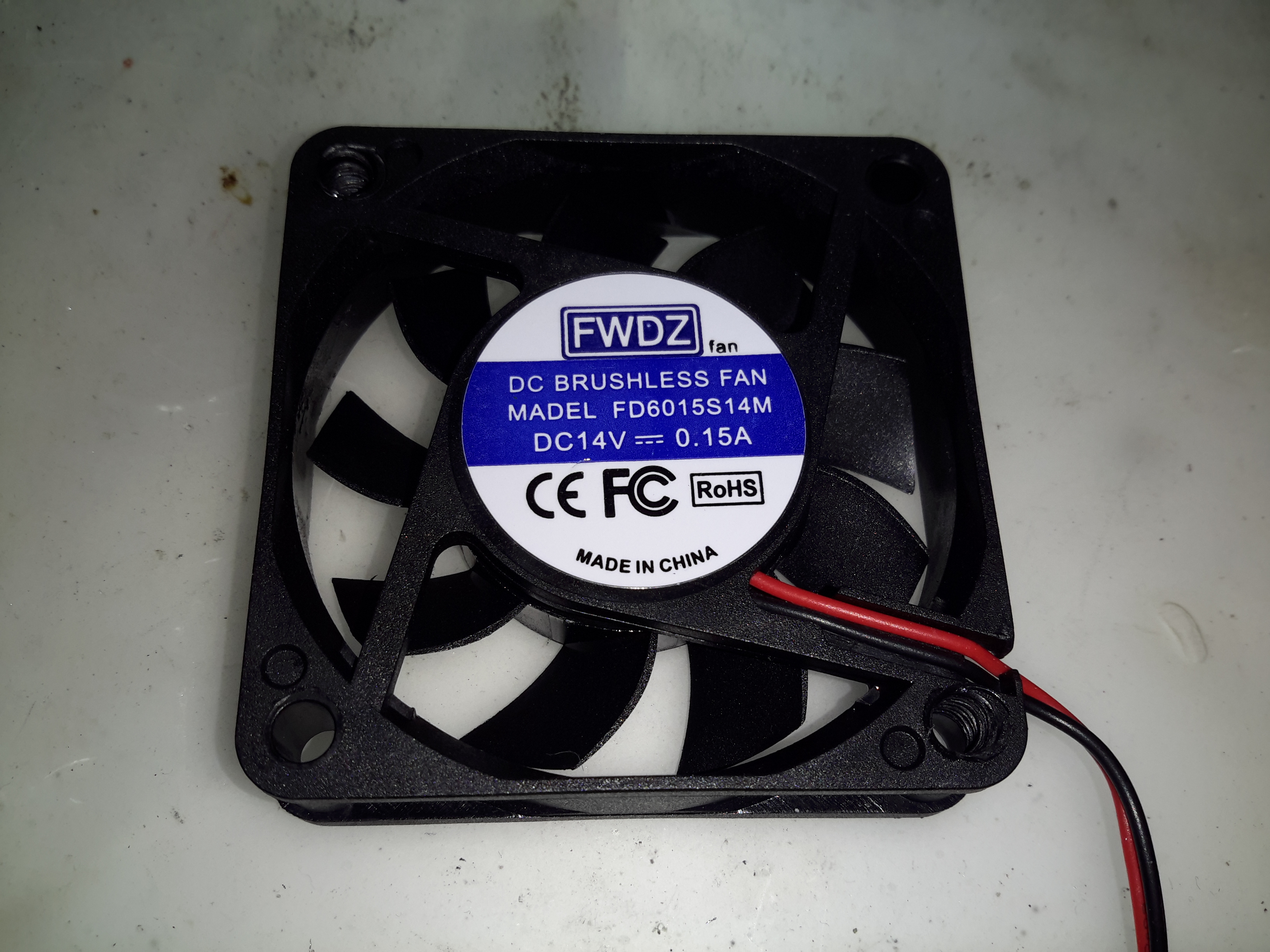
The main heatsink is fan cooled, the speed is PWM controlled via the microcontroller depending on the temperature.

Main MOSFET
Main MOSFET

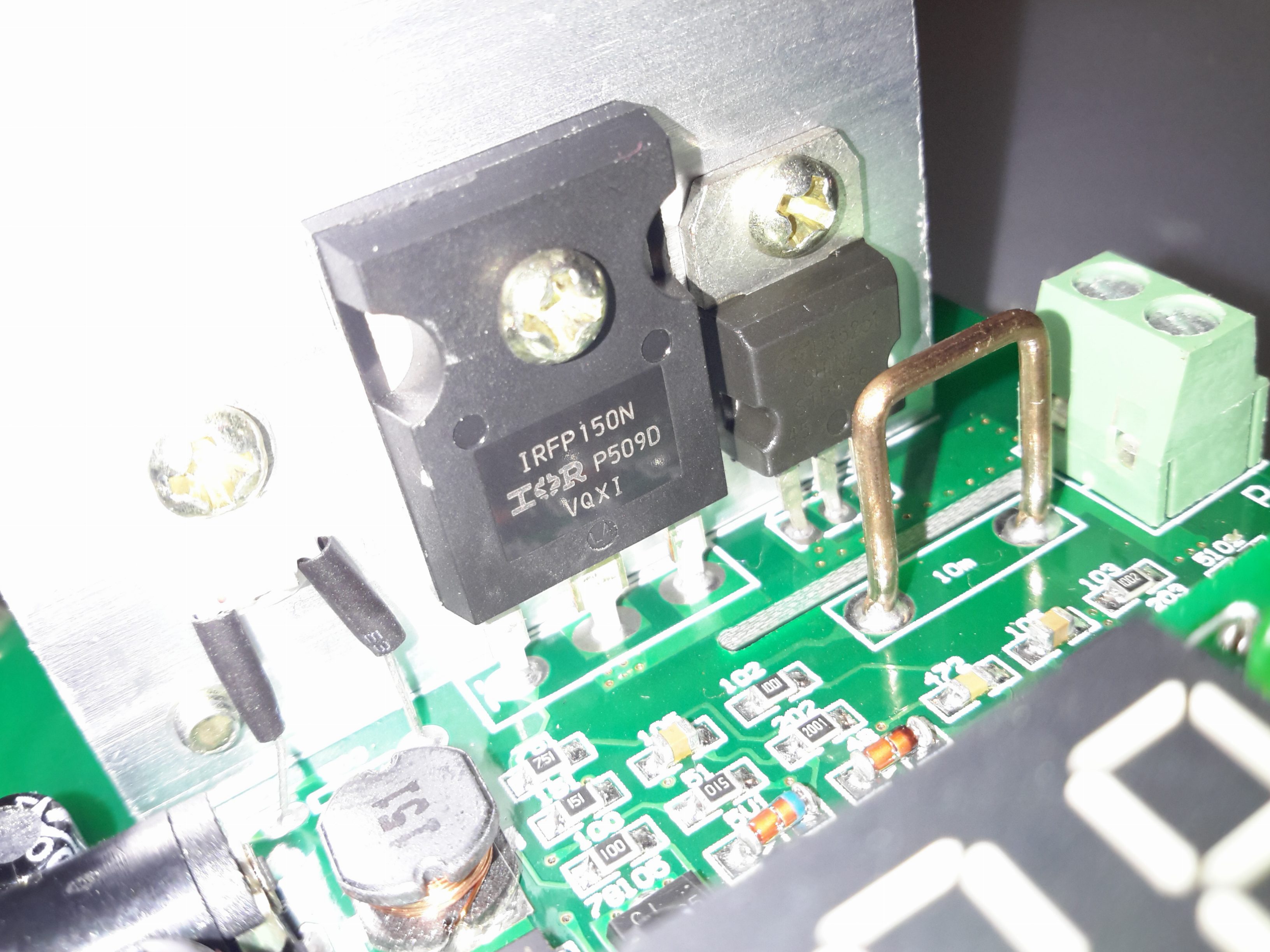
The main load MOSFET is an IRFP150N from Infineon. This device is rated at 100v 42A, with a max power dissipation of 160W. On the right is a dual diode for reverse polarity protection, this is in series with the MOSFET. On the left is the thermistor for controlling fan speed.

Load Terminals
Load Terminals

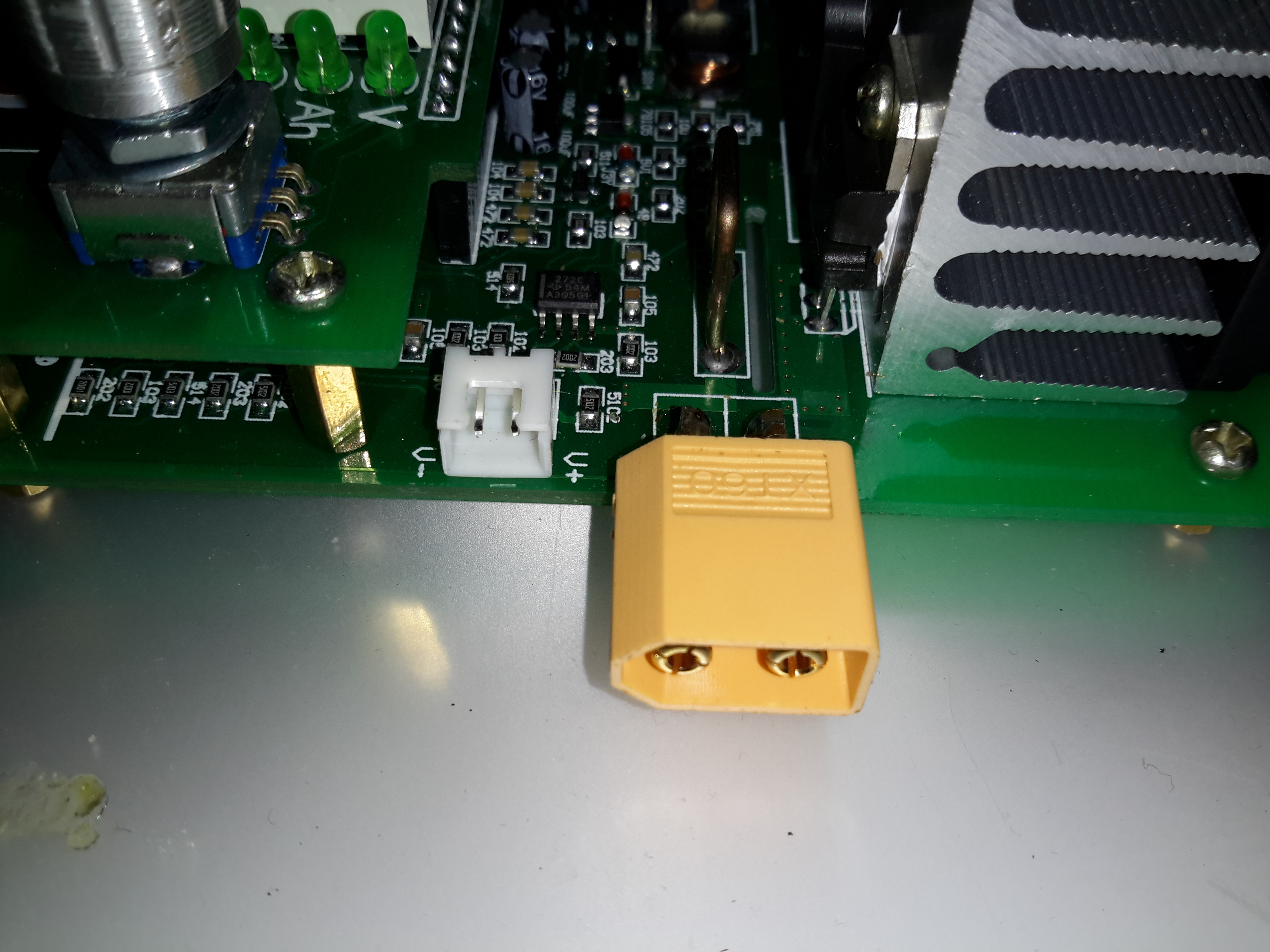
The load is usually connected via a rising clamp terminal block. I’ve replaced it with a XT60 connector in this case as all my battery holders are fitted with these. This also removes the contact resistance of more connections for an adaptor cable. The small JST XH2 connector on the left is for remote voltage sensing. This is used for 4-wire measurements.

Function 1 - DC Load
Function 1 – DC Load

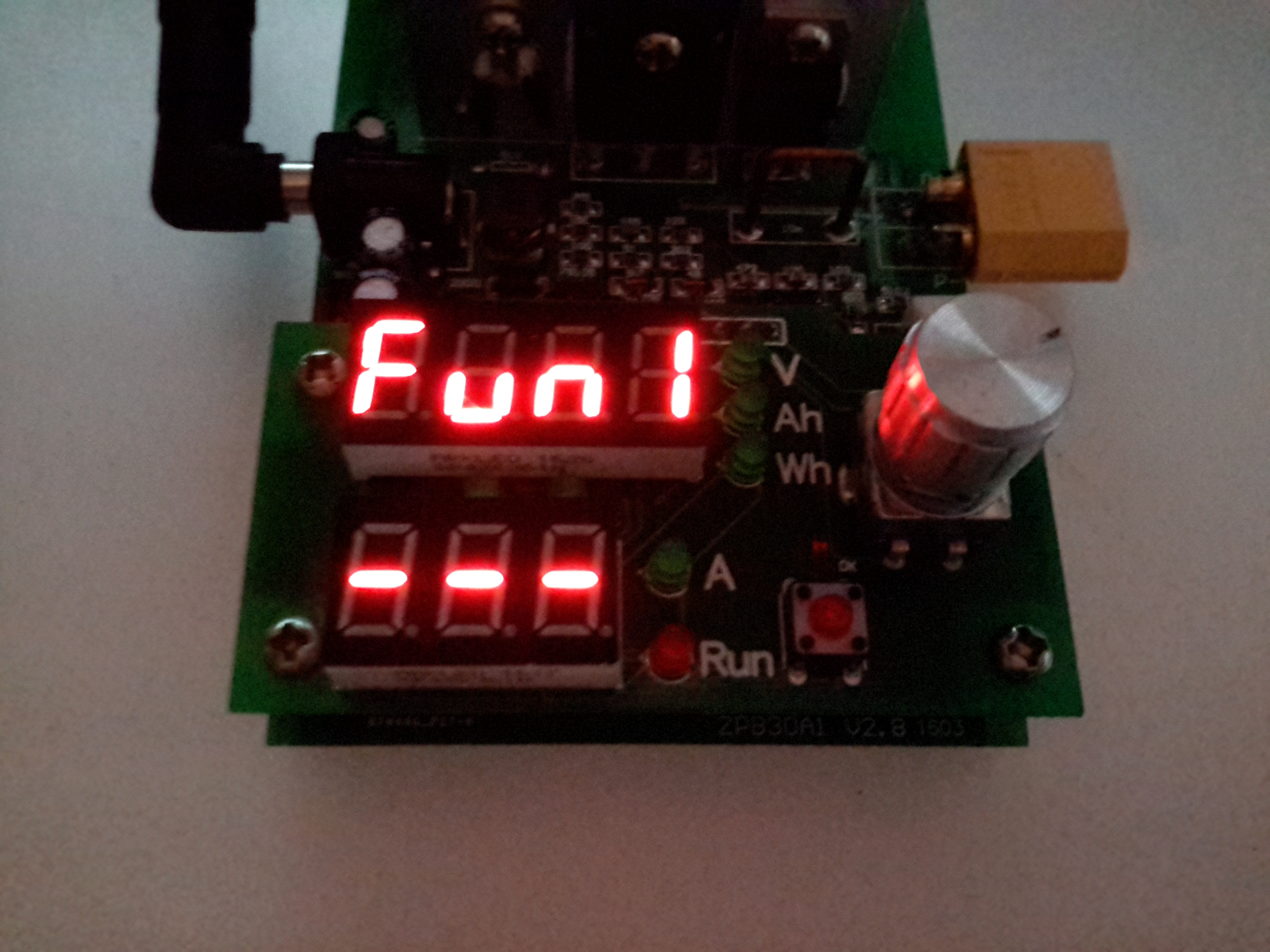
Powering the device up while holding the RUN button gets you into the menu to select the operating modes. Function 1 is simple DC load.

Function 2 - Battery Capacity Mode
Function 2 – Battery Capacity Mode

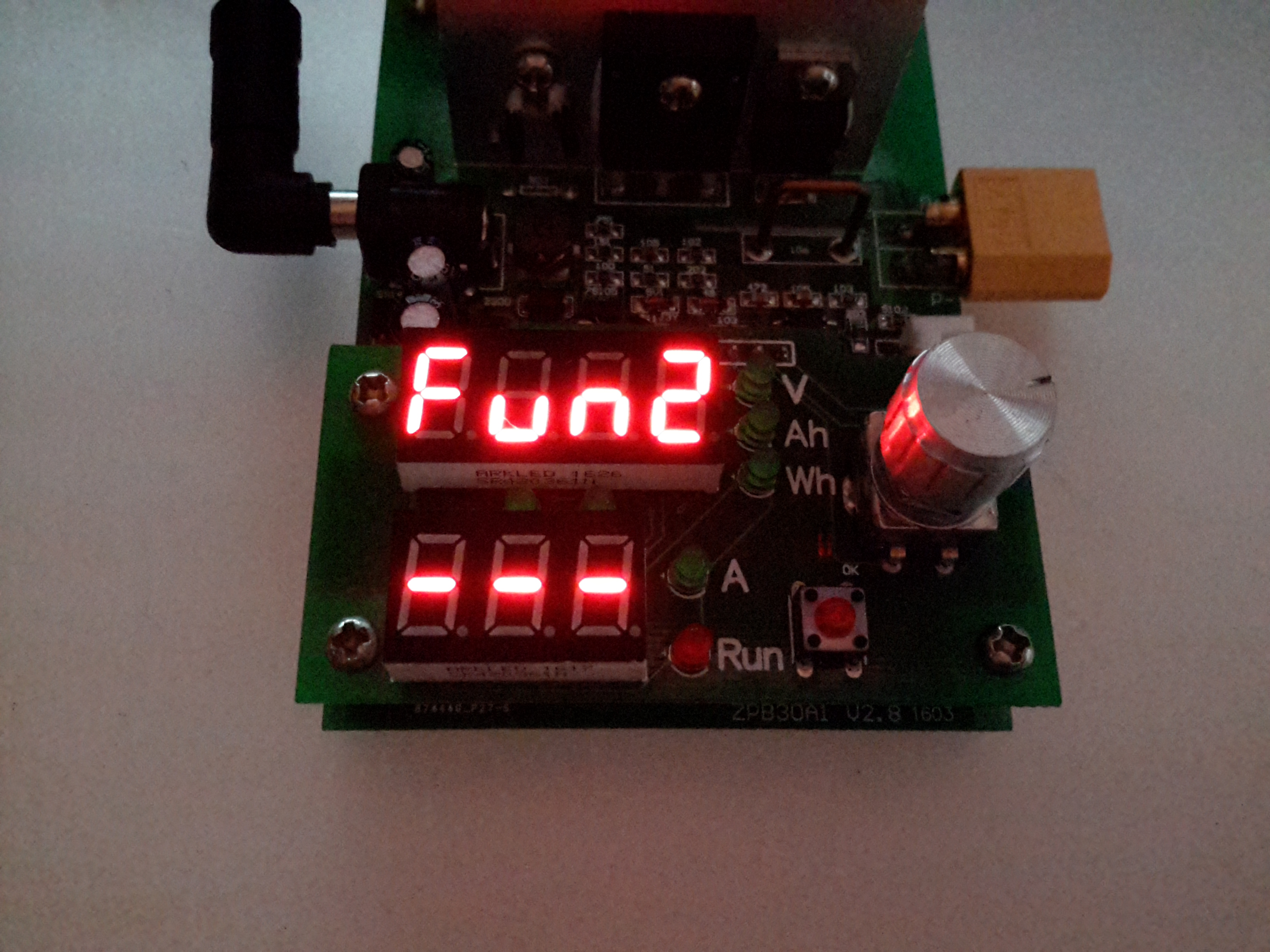
The rotary encoder is used to select the option. Function 2 is battery capacity test mode.

Beeper Mode
Beeper Mode

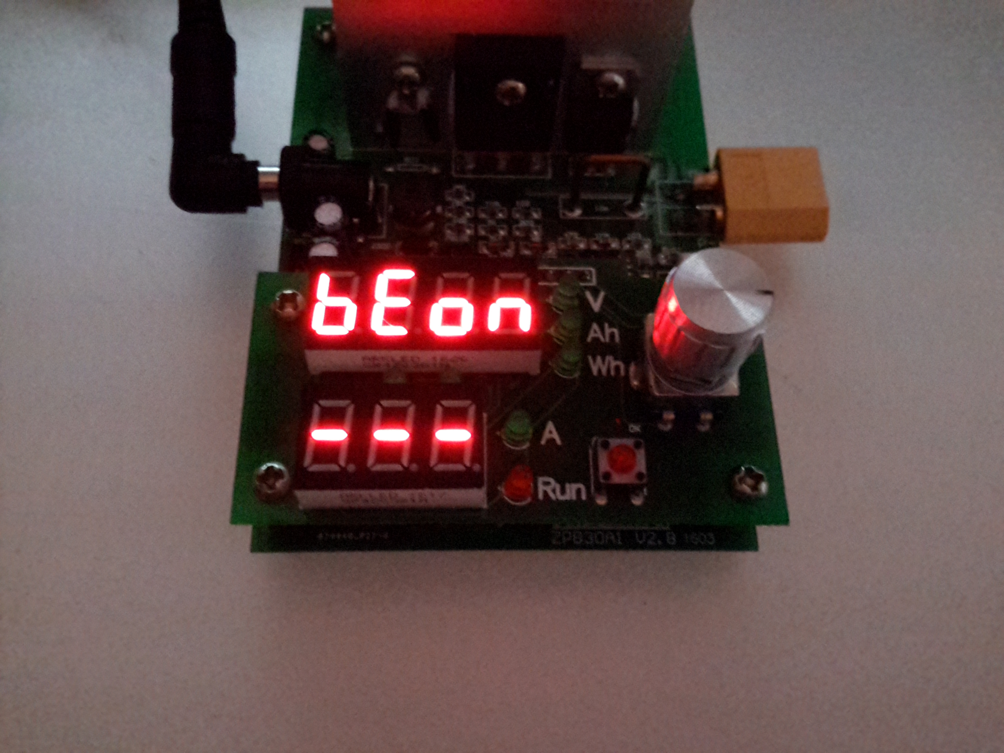
After the mode is selected, an option appears to either turn the beeper on or off.

Amps Set
Amps Set

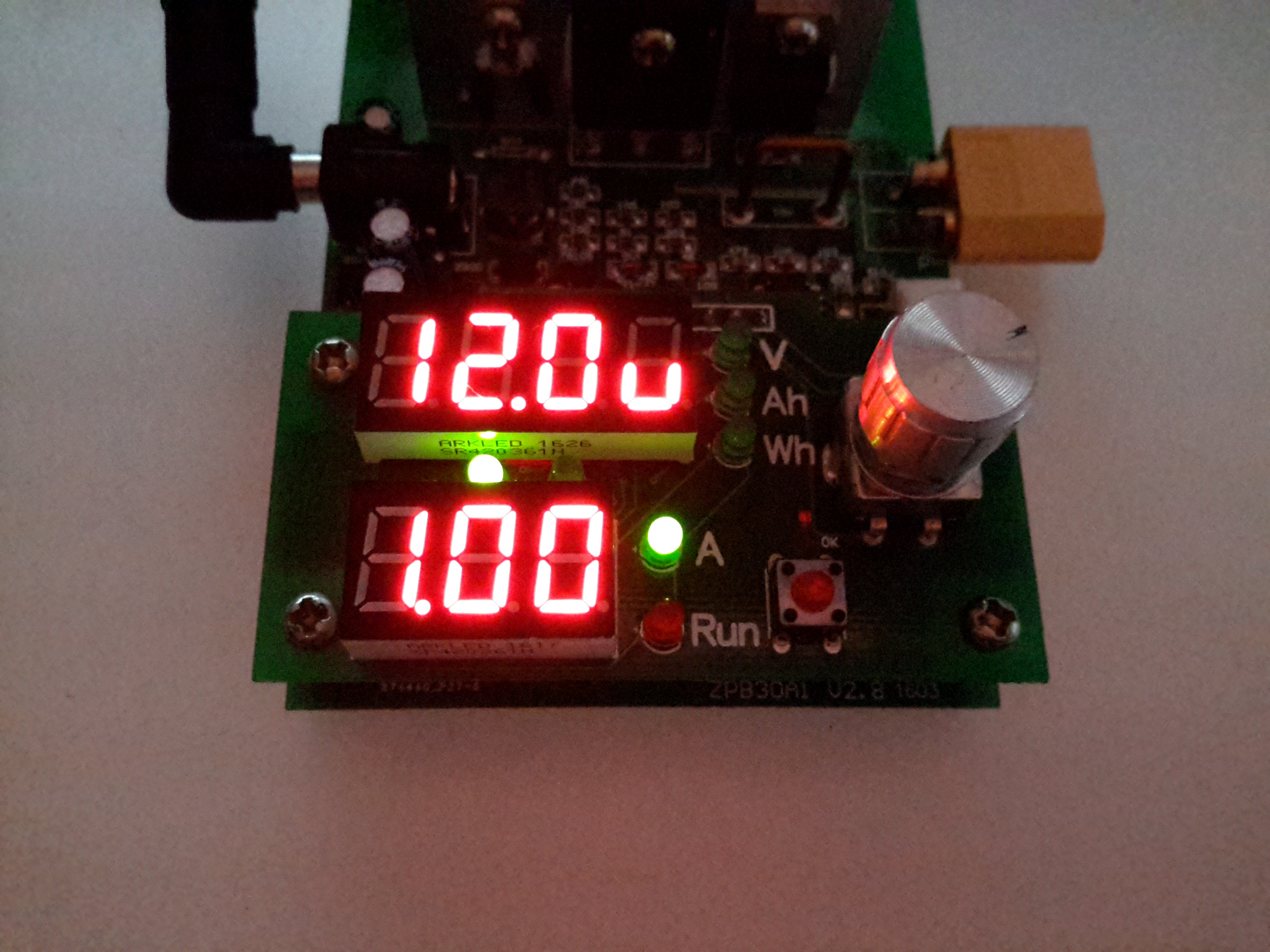
When in standby mode, the threshold voltage & the load current can be set. Here the Amps LED is lit, so the load current can be set. The pair of LEDs between the displays shows which digit will be changed. Pressing the encoder button cycles through the options.

Volts Set
Volts Set

With the Volts LED lit, the threshold voltage can be changed.

When in DC load mode (Fun1), the device will place a fixed load onto the power source until it’s manually stopped. The voltage setting in this mode is a low-voltage alarm. The current can be changed while the load is running.

When in battery discharge test mode (Fun2), the voltage set is the cutoff voltage – discharge will stop when this is reached. Like the DC load mode, the current can be changed when the load is running. After the battery has completed discharging, the capacity in Ah & Wh will be displayed on the top 7-segment. These results can be selected between with the encoder.

Below are tables with all the options for the unit, along with the error codes I’ve been able to decipher from the Chinese info available in various places online. (If anyone knows better, do let me know!).

OptionFunction
Fun1Basic DC Load
Fun 2Battery Capacity Test
BeOnBeeper On
BeOfBeeper Off
Error CodeMeaning
Err1Input Overvoltage
Err2Low Battery Voltage / No Battery Present / Reverse Polarity
Err3Battery ESR Too High / Cannot sustain selected discharge current
Err4General Failure
Err6Power Supply Voltage Too Low / Too High. Minimum 12v 0.5A.
otPOvertemperature Protection
ErtTemperature Sensor Failure / Temperature Too Low
ouPPower Supply Overvoltage Protection
oPPLoad Power Protection
Posted on Leave a comment

eBay Chinese Chassis Power Supply S-400-12 400W 12v 33A

S-400-12 PSU
S-400-12 PSU

Here’s a cheap PSU from the treasure trove of junk that is eBay, rated at a rather beefy 400W of output at 12v – 33A! These industrial-type PSUs from name brands like TDK-Lambda or Puls are usually rather expensive, so I was interested to find out how much of a punishment these cheap Chinese versions will take before grenading. In my case this PSU is to be pushed into float charging a large lead acid battery bank, which when in a discharged state will try to pull as many amps from the charger as can be provided.

Rating Label
Rating Label

These PSUs are universal input, voltage adjustable by a switch on the other side of the PSU, below. The output voltage is also trimmable from the factory, an important thing for battery charging, as the output voltage needs to be sustained at 13.8v rather than the flat 12v from the factory.

Input Voltage Selector
Main Terminal Block
Main Terminal Block

Mains connections & the low voltage outputs are on beefy screw terminals. The output voltage adjustment potentiometer & output indicator LED are on the left side.

Cooling Fan
Cooling Fan

The cooling fan for the unit, which pulls air through the casing instead of blowing into the casing is a cheap sleeve bearing 60mm fan. No surprises here. I’ll probably replace this with a high-quality ball-bearing fan, to save the PSU from inevitable fan failure & overheating.

PCB Bottom
PCB Bottom

The PCB tracks are generously laid out on the high current output side, but there are some primary/secondary clearance issues in a couple of places. Lindsay Wilson over at Imajeenyus.com did a pretty thorough work-up on the fineries of these PSUs, so I’ll leave most of the in-depth stuff via a linky. There’s also a modification of this PSU for a wider voltage range, which I haven’t done in this case as the existing adjustment is plenty wide enough for battery charging duty.

Bare PCB
Bare PCB

The PCB is laid out in the usual fashion for these PSUs, with the power path taking a U-route across the board. Mains input is lower left, with some filtering. Main diode bridge in the centre, with the voltage selection switch & then the main filter caps. Power is then switched into the transformer by the pair of large transistors on the right before being rectified & smoothed on the top left.

Main Switching Transistors

The pair of main switching devices are mounted to the casing with thermal compound & an insulating pad. To bridge the gap there’s a chunk of aluminium which also provides some extra heatsinking.

SMPS Drive IC & Base Drive Transformer

The PSU is controlled by a jelly-bean TL494 PWM controller IC. No active PFC in this cheap supply so the power factor is going to be very poor indeed.

Input Protection
Input Protection

Input protection & filtering is rather simple with the usual fuse, MOV filter capacitor & common mode choke.

Main Output Rectifiers

Beefy 30A dual diodes on the DC output side, mounted in the same fashion as the main switching transistors.

Output Current Shunt

Current measurement is done by these large wire links in the current path, selectable for different models with different output ratings.

Hot Glue Support
Hot Glue Support

The output capacitors were just floating around in the breeze, with one of them already having broken the solder joints in shipping! After reflowing the pads on all the capacitors some hot glue as flowed around them to stop any further movement.

This supply has now been in service for a couple of weeks at a constant 50% load, with the occasional hammering to recharge the battery bank after a power failure. at 13A the supply barely even gets warm, while at a load high enough to make 40A rated cable get uncomfortably warm (I didn’t manage to get a current reading, as my instruments don’t currently go high enough), the PSU was hot in the power semiconductor areas, but seemed to cope at full load perfectly well.

Posted on Leave a comment

Belling Microwave


Front
Front

Here is a cheap no frills microwave oven, which died after a few weeks of normal use.

Electronics Bay
Electronics Bay

Cover removed, showing the internals. Front of the microwave is on the left.

Timer
Timer

Closeup of the timer unit. Cheap & nasty.

Magnetron
Magnetron

Magnetron removed from the oven. Antenna is on the top,  cooling fins visible in the center. White conector at the bottom is the filament terminals.

Magnetron Chokes
Magnetron Chokes

Chokes on the magnetron’s filament connections. These prevent microwave energy from feeding back into the electronics bay through the connections.

Magnetron Assembly
Magnetron Assembly

Magnetron cooling fins, tube & magnets removed from the frame.

Magnetron Tube
Magnetron Tube

Bare magnetron tube.

Power Input Board
Power Input Board

This PCB does some rudimentary power conditioning, power resistors are in series with the live feed to the power trasformer, to prevent huge power up surge. When the transformer energizes the relay, which is in parallel with the resistors, switches them out a fraction of a second after, providing full power to the transformer.
Standard RFI choke & capacitor at the top of the board, with the input resistor.

Transformer
Transformer

Power transformer to supply the magnetron with high voltage.
Power output is ~2kV at ~0.5A. Pair of spade terminals are the low voltage filament winding.

Capacitor
Capacitor

HV Capacitor. This along with the diode form a voltage doubler, to provide the magnetron with ~4kV DC.

Diode
Diode

HV diode stack.

Fuse Element
Fuse Element

Internals of the HV fuse. Rated for ~0.75A at 5kV. The fuse element is barely visible attached to the end of the spring. Connects between the transformer & the capacitor.

Cooling Fan
Cooling Fan

Cooling fan for the magnetron. Drive is cheap shaded pole motor.

Fan Motor
Fan Motor

Fan motor. Basic 240v shaded pole induction type.

Posted on Leave a comment

Bosch GSR 14.4v Pro Drill-Driver

Drill Case
Drill Case

Here is a Bosch 14.4v Professional cordless drill/driver, recovered from a skip!
It was thrown away due to a gearbox fault, which was easy to rectify.

Internals
Internals

Here is the drill with the side cover removed, showing it’s internal parts. The speed controller is below the motor & gearbox here. The unit at the top consists of a 12v DC motor, coupled to a 4-stage  epicyclic gearbox unit, from which can be selected 2 different ratios, by way of the lever in the centre of the box. This disables one of the gear stages. There is a torque control clutch at the chuck end of the gearbox, this was faulty when found.

Motor
Motor

Here is the drive motor disconnected from the gearbox, having a bayonet fitting on the drive end.

Drive Gear
Drive Gear

This is the primary drive gear of the motor, which connects with the gearbox.

Cooling Fan
Cooling Fan

The motor is cooled by this fan inside next to the commutator, drawing air over the windings.

Gearbox
Gearbox

This is the gearbox partially disassembled, showing the 1st & second stages of the geartrain. The second stage provides the 2 different drive ratios by having the annulus slide over the entire gearset, disabling it entirely, in high gear. The annulus gears are a potential weak point in this gearbox, as they are made from plastic, with all other gears being made of steel.

Charger
Charger

Here is the charging unit for the Ni-Cd battery packs supplied with the drill. The only indicator is the LED shown here on the front of the unit, which flashes while charging, & comes on solid when charging is complete. Charge termination is by way of temperature monitoring.

Transformer
Transformer

Here the bottom of the charger has been removed, showing the internal parts. An 18v transformer supplies power to the charger PCB on the left.

Charger PCB
Charger PCB

This is the charger PCB, with a ST Microelectronics controller IC marked 6HKB07501758. I cannot find any information about this chip.

Battery Pack Internals

Here is a battery pack with the top removed, showing the cells.

Temperature Sensor
Temperature Sensor

This is the temperature sensor embedded inside the battery pack that is used by the charger to determine when charging is complete.