Posted on 5 Comments

Wheelchair Motors Part 2: Service

Cleaning, Replacement Parts & Reassembly

Housing Cleaned
Housing Cleaned

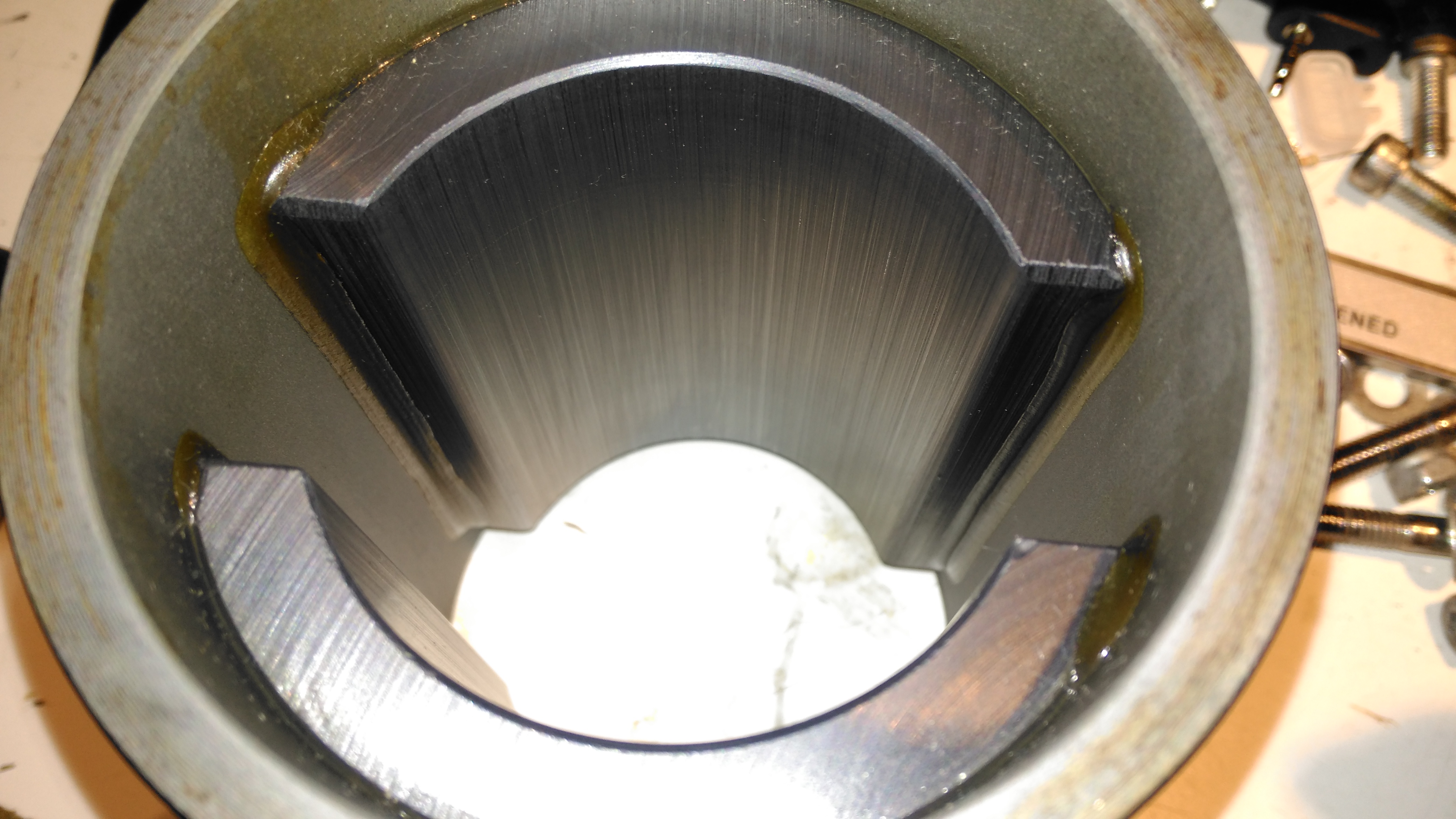
The housing of the contaminated motor was left to soak in diesel for a few hours to loosen the grok, this has come very clean. I couldn’t have used a stronger solvent here – the magnets are glued in place in the steel housing, I certainly didn’t want them coming loose!

Brushboxes
Brushboxes

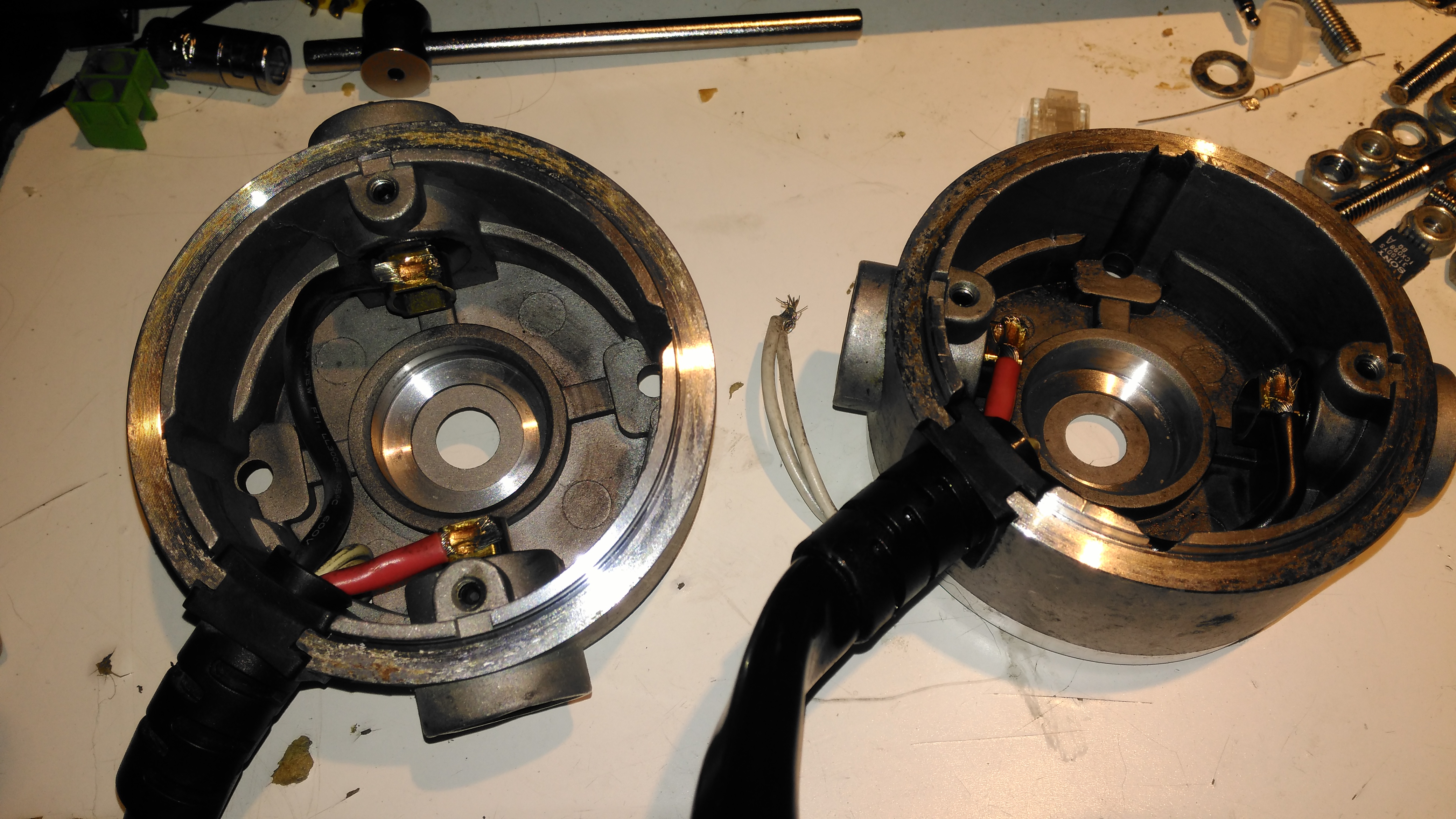
Next into the diesel bath are the motor end bells with the brushgear. Attack with a stiff brush cleaned these up very well, some cotton buds served to clean out the brass brush holders.

Armatures After Skimming

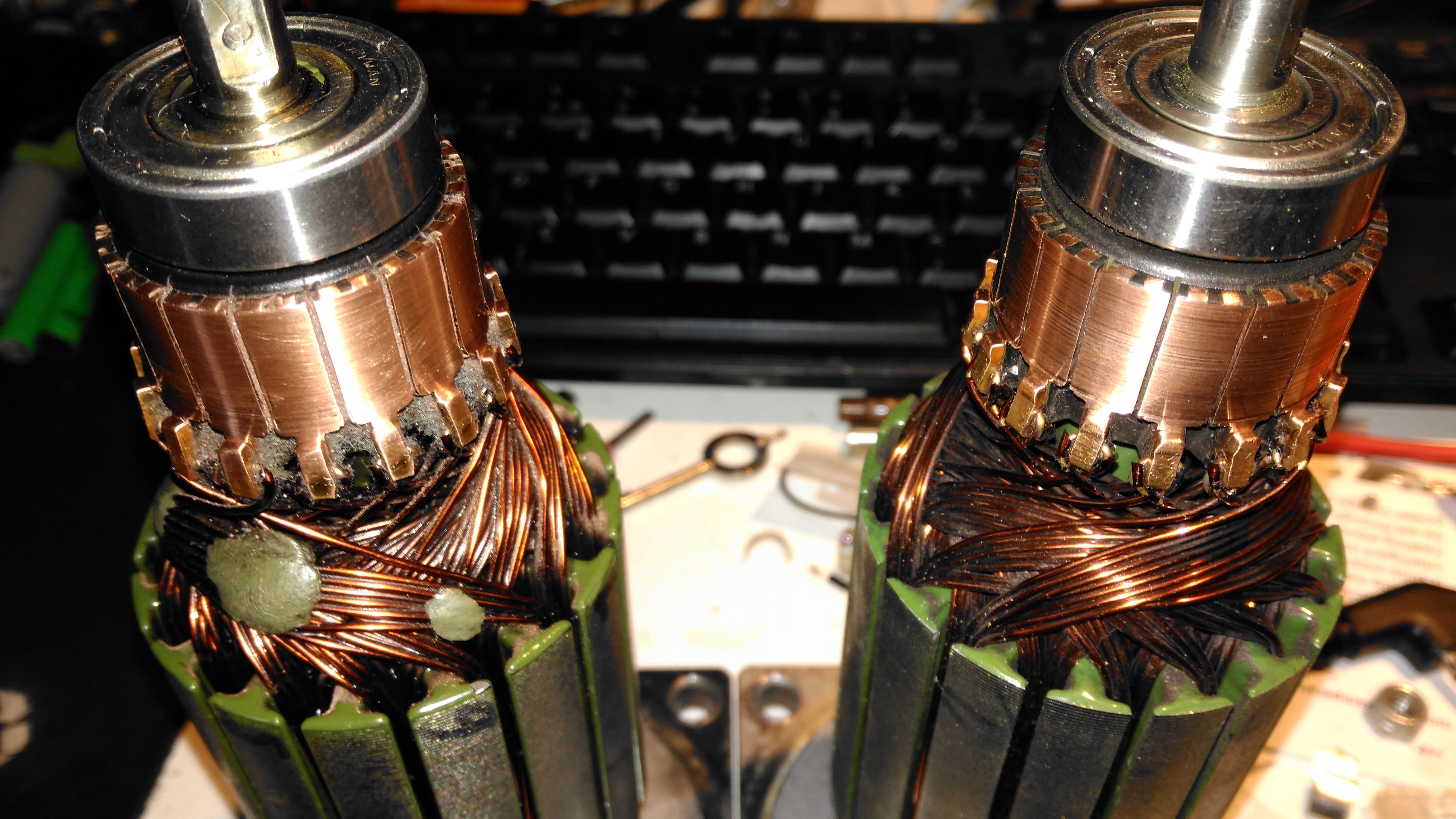
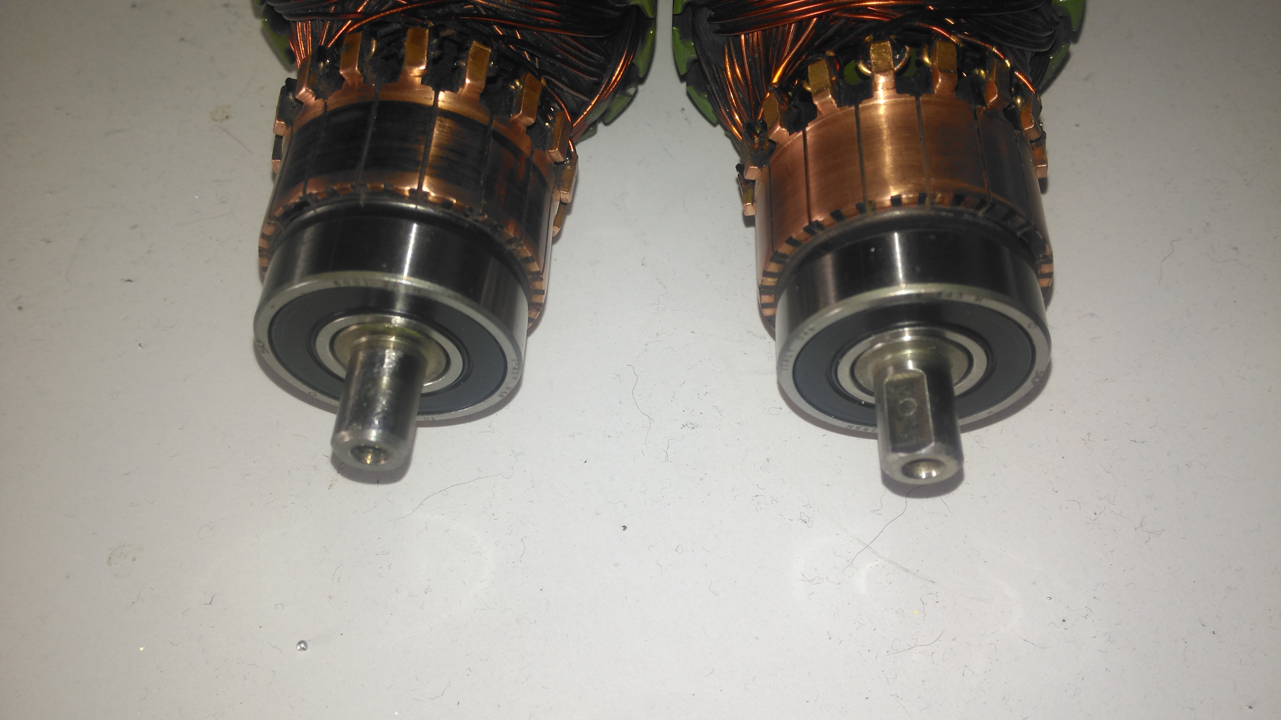
Here are both armatures, having had their commutators resurfaced. I’ve completely removed all traces of the wear caused by the contamination, luckly the commutator bars are very heavy on these motors so can take quite a bit of wear before there’s not enough left to skim. I’ve not yet pulled off the old bearings, but they are all going to be replaced with new SKF bearings, as they’ve been contaminated with grok over the years of use. I’m also going to uprate the front motor bearings to rubber sealed instead of metal shielded, to help keep lubricant out of the motors if the gearbox seals ever fail again.

Gearbox
Gearbox

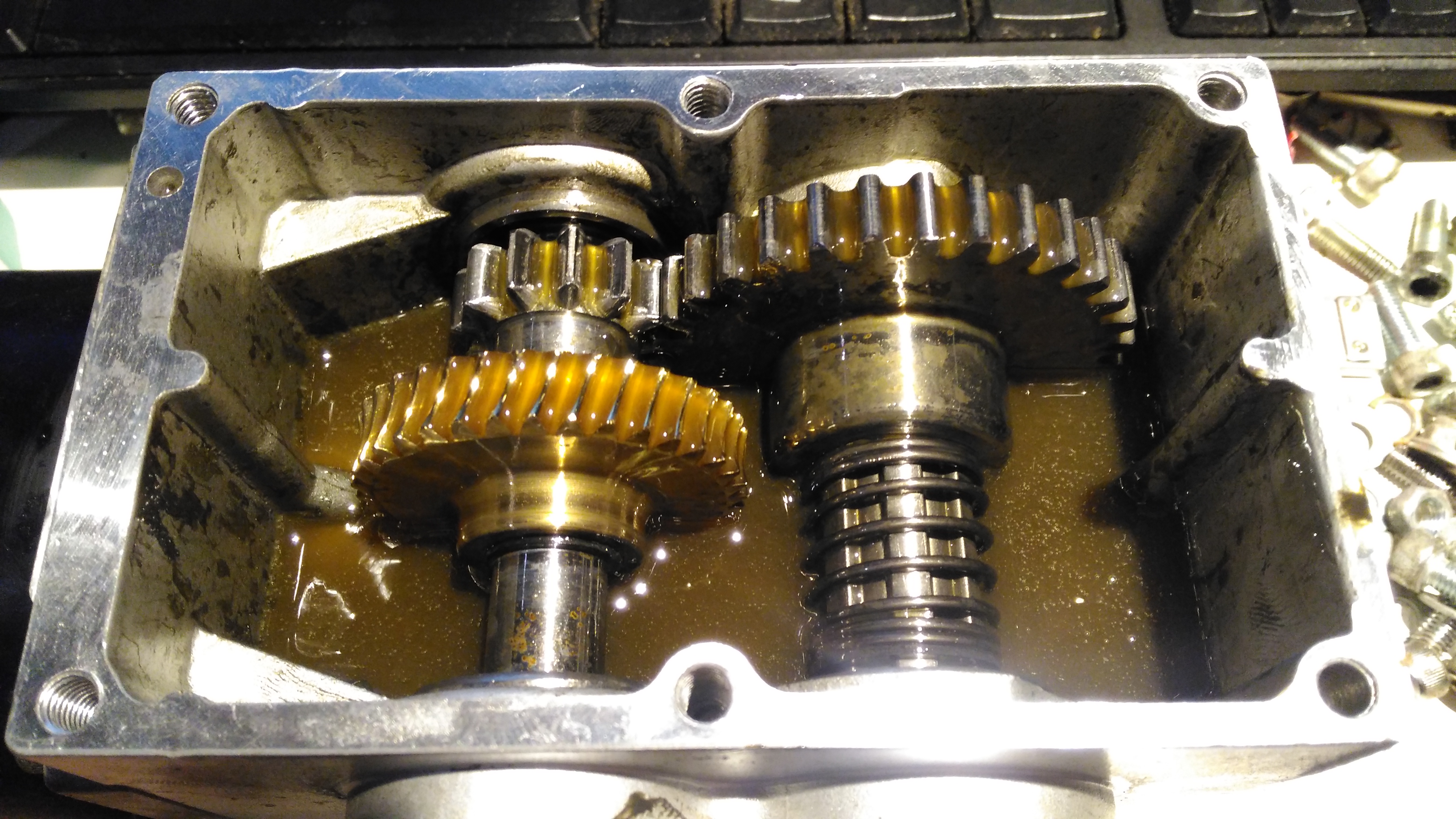
The gearboxes have been cleaned out with some elbow grease, assisted by a long soak in petrol, I’ve refilled them here with engine oil as temporary lube & to flush out the last remains of the old grease & solvent. The worm wheel in these boxes is bronze – so a GL4 gear oil will be required. (Some Extreme Pressure additive packs contain sulphur, and will readily attack copper alloys, such as brass & bronze).

Commutator End Bearings

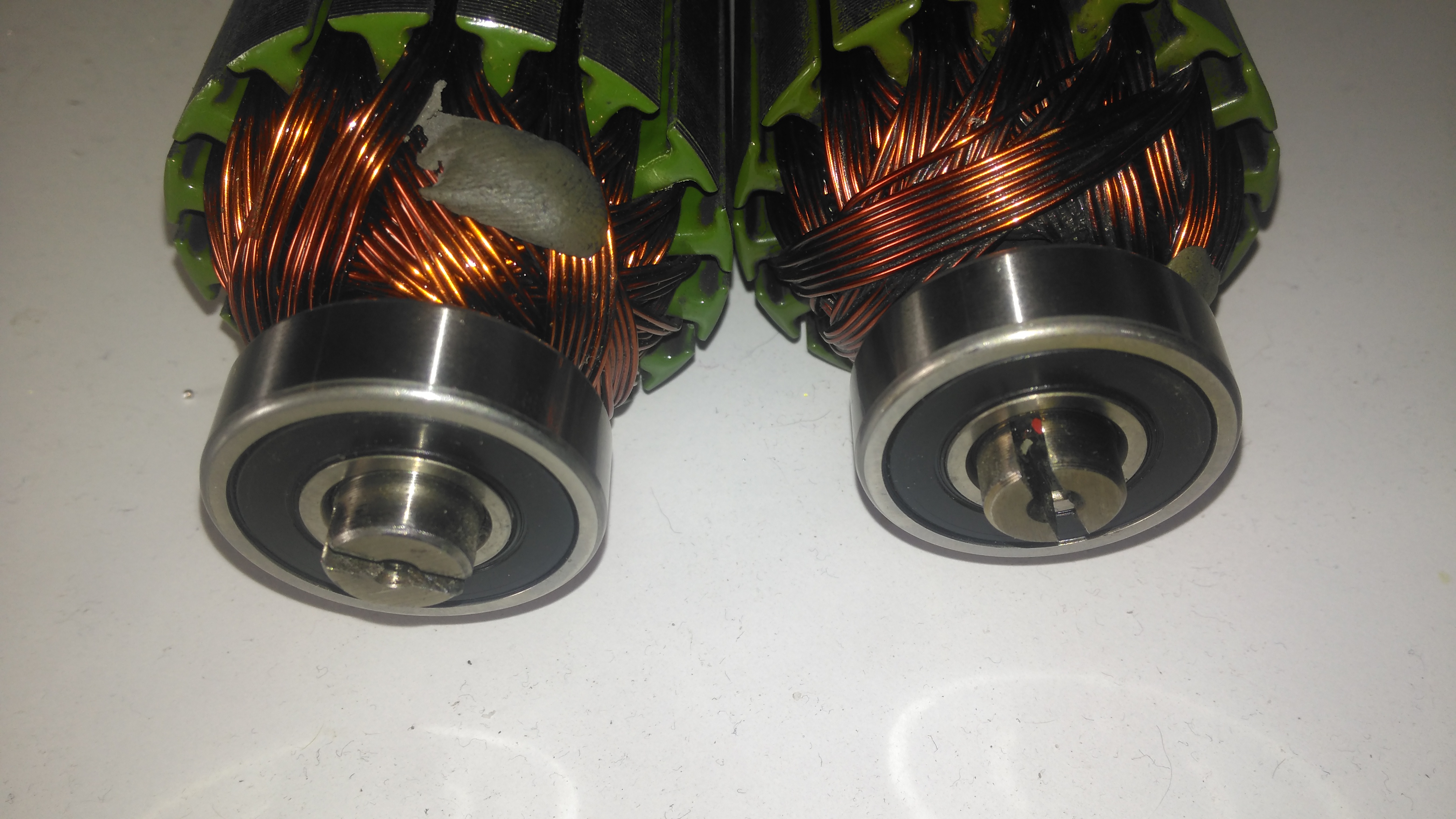
Here’s the armatures, after the new SKF sealed bearings have been fitted to the commutator end, above, and the drive end, below. These will cause some extra drag on the armatures, and slightly higher power consumption as a result, but keeping the crap out of the motors is slightly more important.

Drive End Bearings
Drive End Bearings
Fresh Commutator Skim

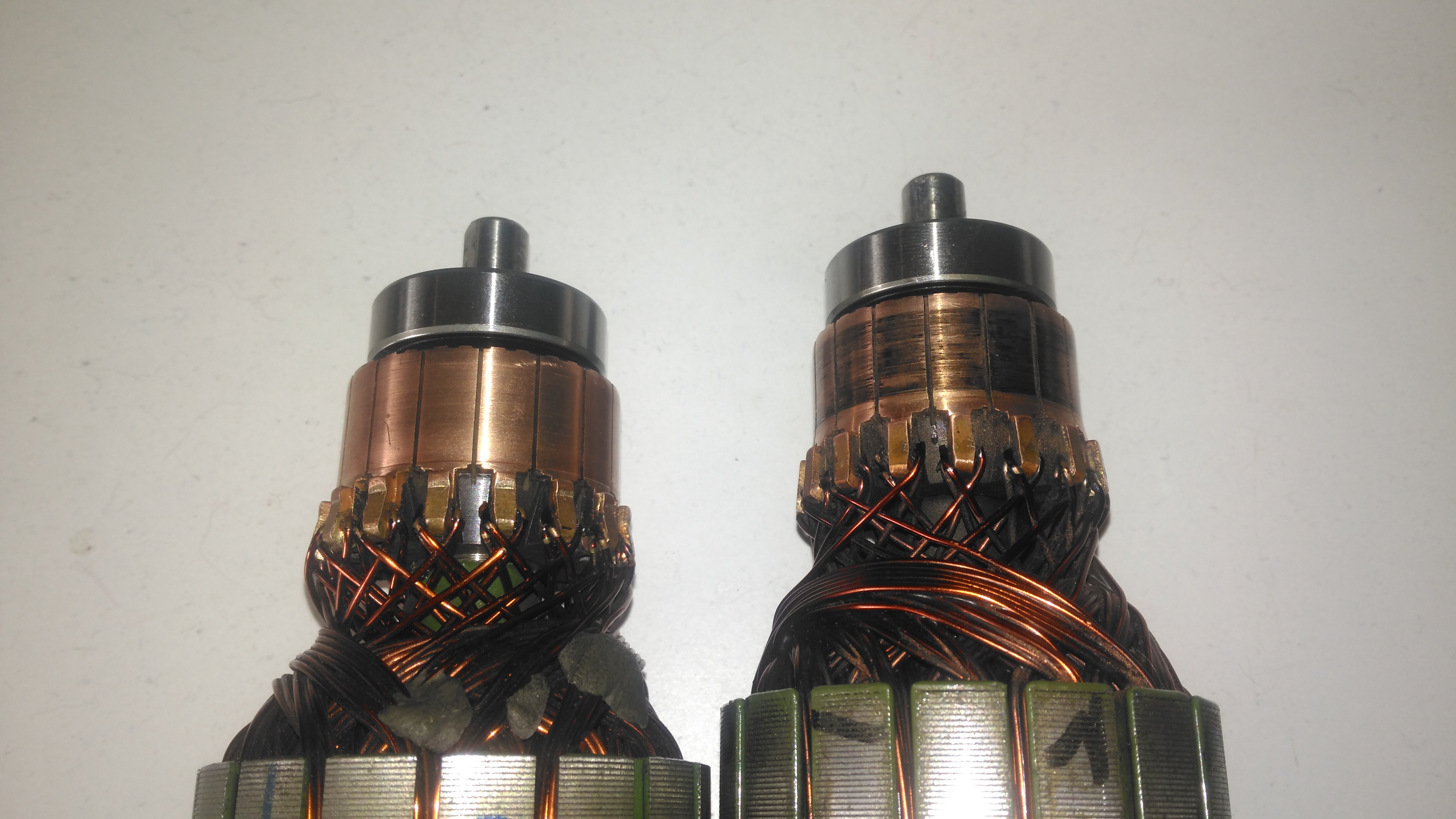
The commutators have been lightly skimmed with abrasive cloth, and finished with 1500 grit emery. The armature on the right has been run for a short time to see how the new brushes are bedding in.

Old Seal Removed
Old Seal Removed

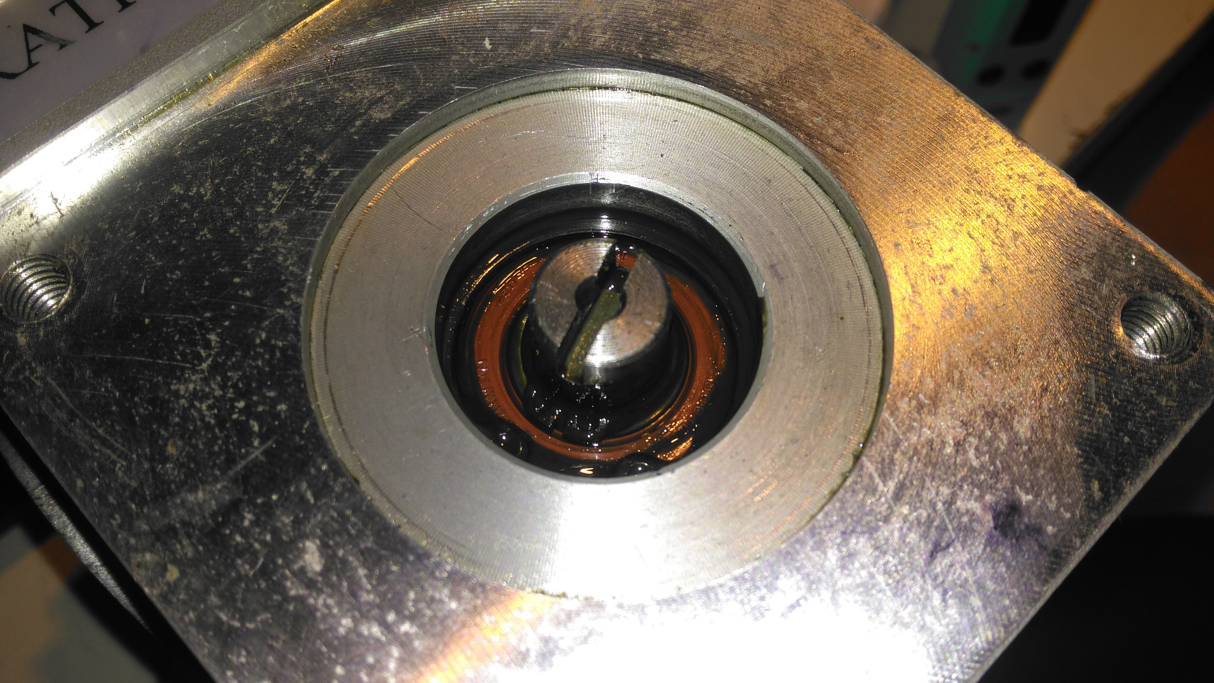
Finally, the old oil seals are pulled from the gearboxes. The worm gear bearing on the inside is actually a sealed version, with the external oil seal providing some extra sealing. I haven’t changed the gearbox bearings, as they seem to be in good order, this might get done at some point in the future.

New Oil Seals
New Oil Seals

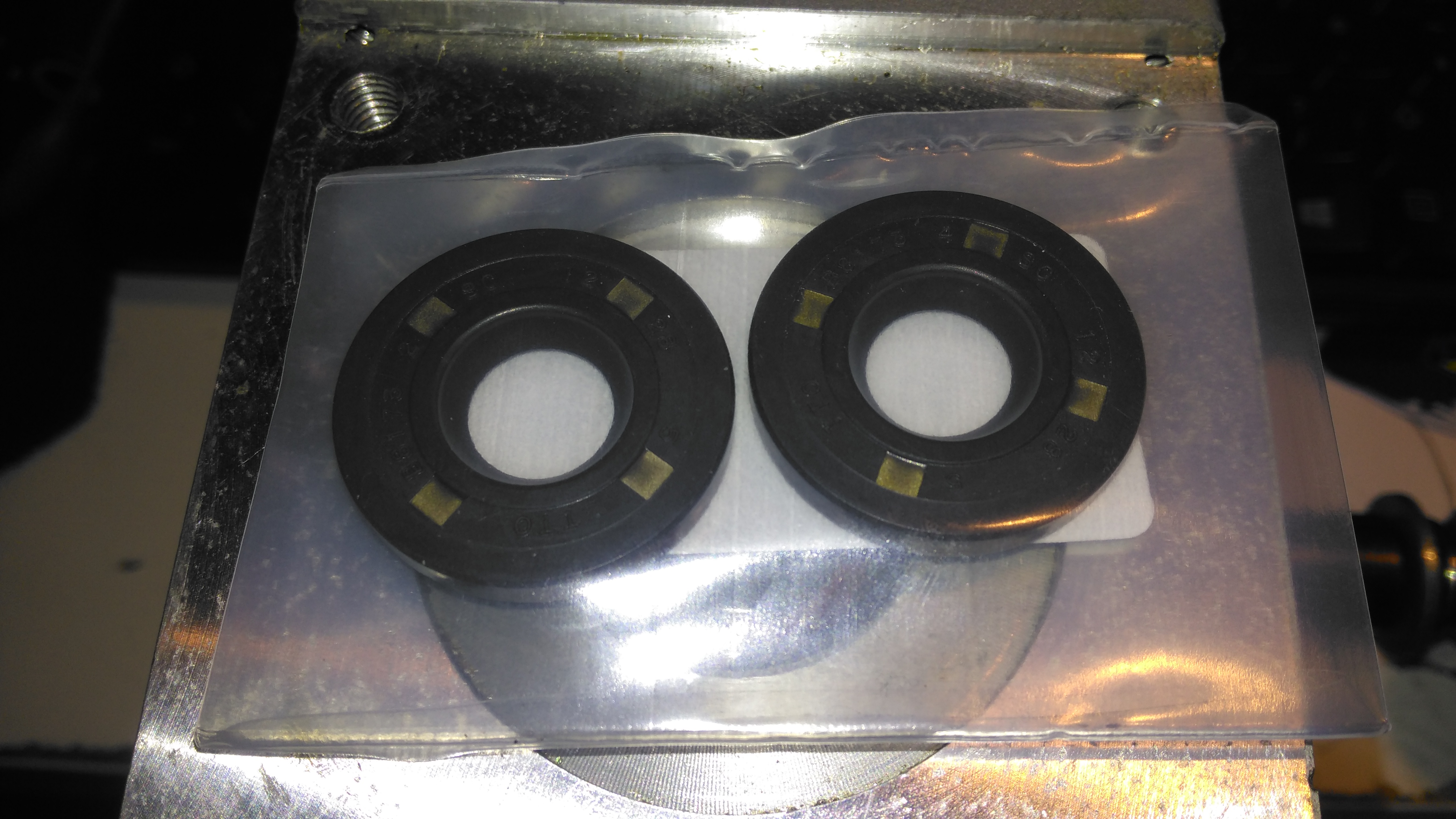
The new seals ready to be driven into the bores.

Posted on 1 Comment

Brightwell Brightstar II BSL4 Dosing System

Overview
Overview
Overview

Here is an old chemical dosing system for industrial washing machines. These units are 4-pump models, with dual pumpheads. The motors are reversed to operate alternate pumps in the same head.

Label
Label

From 2006, this is a fairly old unit, and made in the UK.

CPU Board
CPU Board

Main controller PCB, with interface to the power electronics via the ribbon cable, an external serial port for programming to it’s left. Powered by an ST microcontroller. The LCD is below this board.

PCU & Driver PCBs
PCU & Driver PCBs

Main power supply, sense input & motor driver boards. The PSU outputs +5v, +12v & +24v. The inputs on the lower left connect to the washing machine & trigger the pumps via the programming on the CPU. The motors are driven by L6202 H-Bridge drivers from ST.

Motor Assembly
Motor Assembly

Motor & gearbox assembly on the back of the pumphead. These are 24v DC units with 80RPM gearboxes.

UPDATE:
As it seems to be difficult to find, here is the user manual for this unit:
[download id=”5557″]

Posted on Leave a comment

Bosch GSR 14.4v Pro Drill-Driver

Drill Case
Drill Case

Here is a Bosch 14.4v Professional cordless drill/driver, recovered from a skip!
It was thrown away due to a gearbox fault, which was easy to rectify.

Internals
Internals

Here is the drill with the side cover removed, showing it’s internal parts. The speed controller is below the motor & gearbox here. The unit at the top consists of a 12v DC motor, coupled to a 4-stage  epicyclic gearbox unit, from which can be selected 2 different ratios, by way of the lever in the centre of the box. This disables one of the gear stages. There is a torque control clutch at the chuck end of the gearbox, this was faulty when found.

Motor
Motor

Here is the drive motor disconnected from the gearbox, having a bayonet fitting on the drive end.

Drive Gear
Drive Gear

This is the primary drive gear of the motor, which connects with the gearbox.

Cooling Fan
Cooling Fan

The motor is cooled by this fan inside next to the commutator, drawing air over the windings.

Gearbox
Gearbox

This is the gearbox partially disassembled, showing the 1st & second stages of the geartrain. The second stage provides the 2 different drive ratios by having the annulus slide over the entire gearset, disabling it entirely, in high gear. The annulus gears are a potential weak point in this gearbox, as they are made from plastic, with all other gears being made of steel.

Charger
Charger

Here is the charging unit for the Ni-Cd battery packs supplied with the drill. The only indicator is the LED shown here on the front of the unit, which flashes while charging, & comes on solid when charging is complete. Charge termination is by way of temperature monitoring.

Transformer
Transformer

Here the bottom of the charger has been removed, showing the internal parts. An 18v transformer supplies power to the charger PCB on the left.

Charger PCB
Charger PCB

This is the charger PCB, with a ST Microelectronics controller IC marked 6HKB07501758. I cannot find any information about this chip.

Battery Pack Internals

Here is a battery pack with the top removed, showing the cells.

Temperature Sensor
Temperature Sensor

This is the temperature sensor embedded inside the battery pack that is used by the charger to determine when charging is complete.