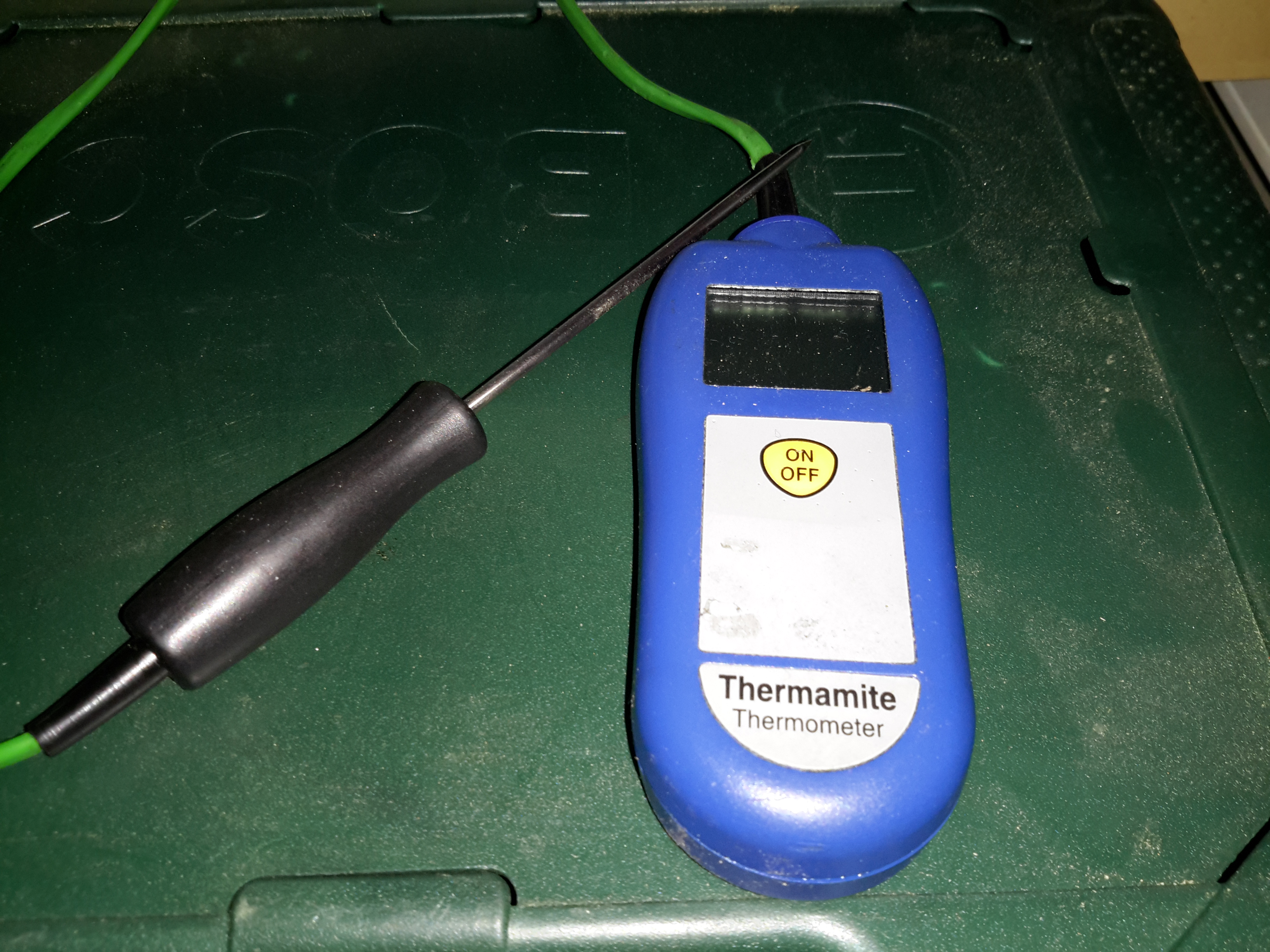
Here’s another bit of commercial gear, a catering thermometer. These are used to check the internal temperature of foods such as meat, to ensure they’re cooked through.
This was given to me with some damage, the battery cover is missing & the plastic casing itself is cracked.
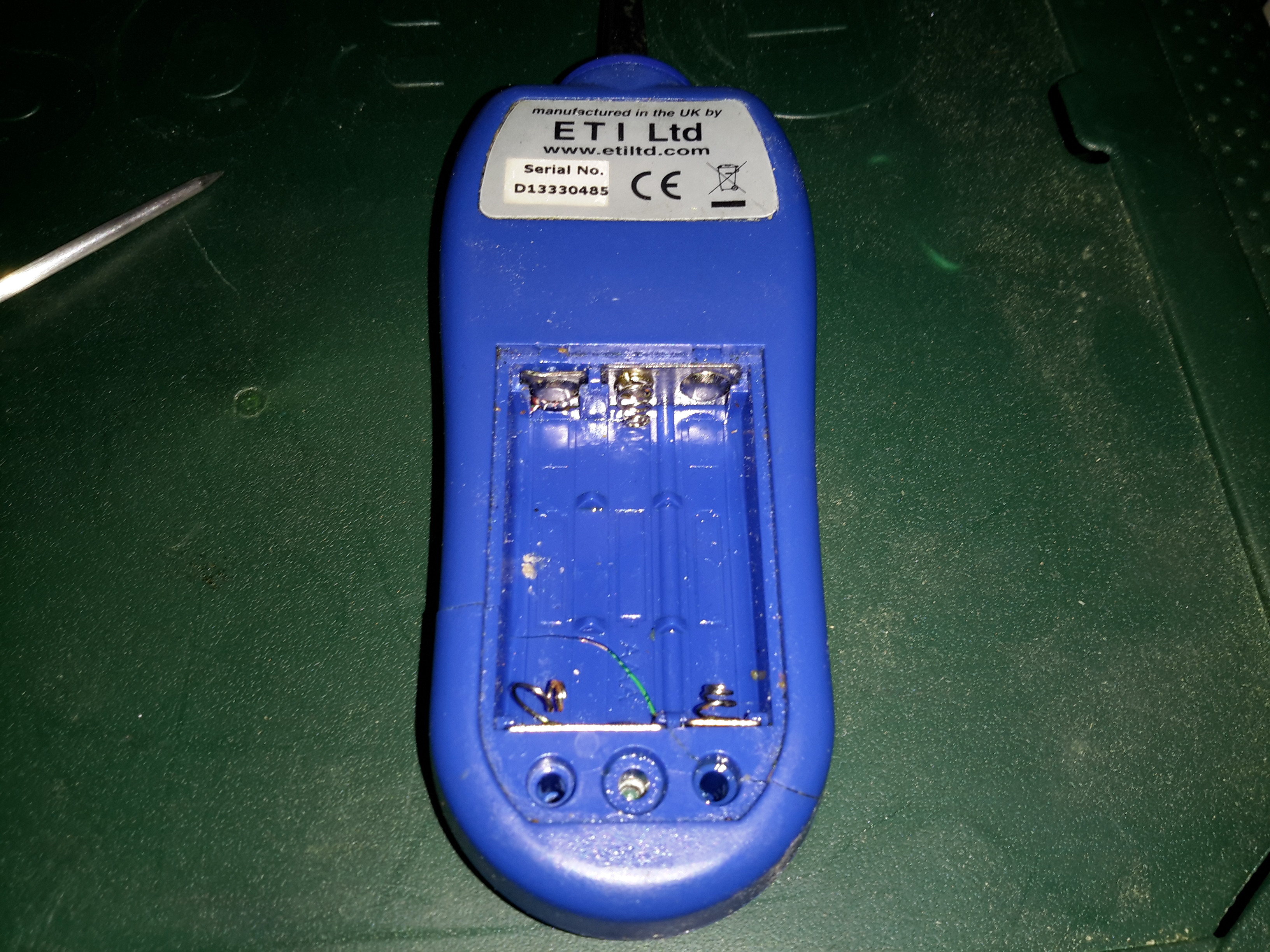
Battery Compartment
Power is provided by 3 AAA cells, for 4.5v
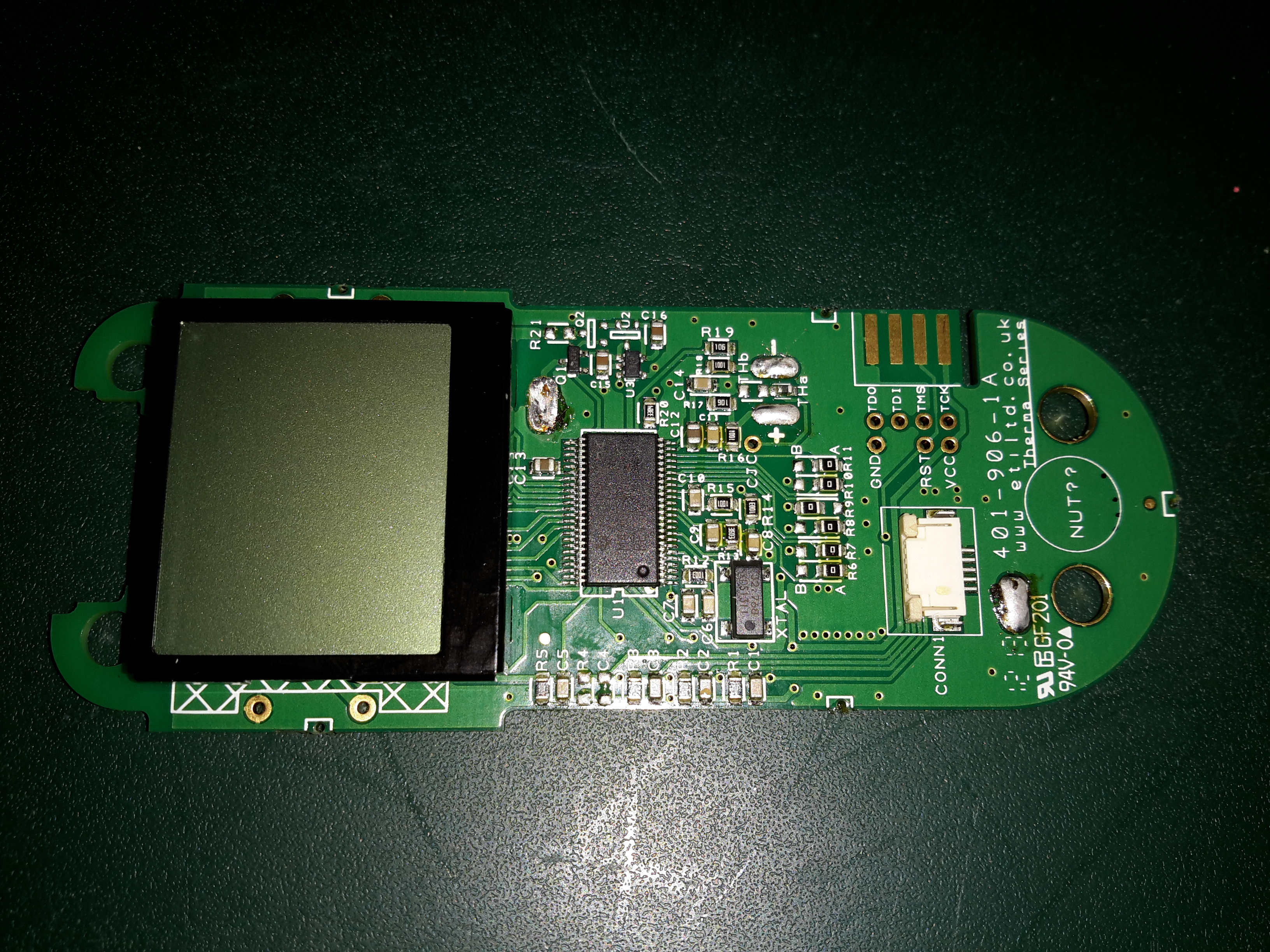
Main PCB
There’s not much to these units, the large LCD at the top is driven by the IC in the centre. A programming header is also present on the board near the edge.
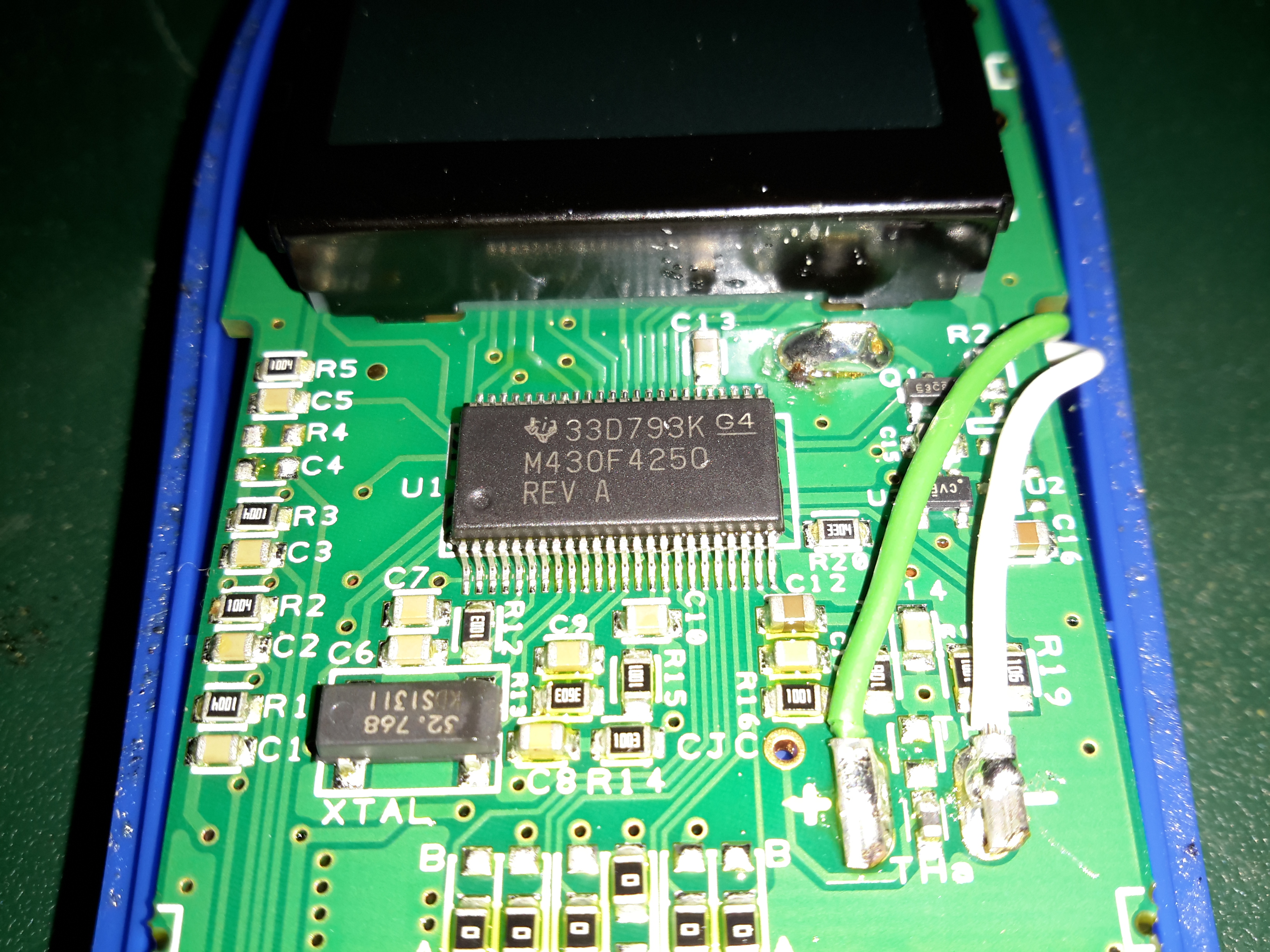
Microcontroller
The core logic is taken care of with a Texas Instruments M430F4250 MSP430 Mixed-Signal Microcontroller. This MCU has onboard 16-bit Sigma-Delta A/D converter, 16-bit D/A converter & LCD driver. Clock is provided by a 32.768kHz crystal.
The probe itself is just a simple thermistor bonded into a stainless steel rod.
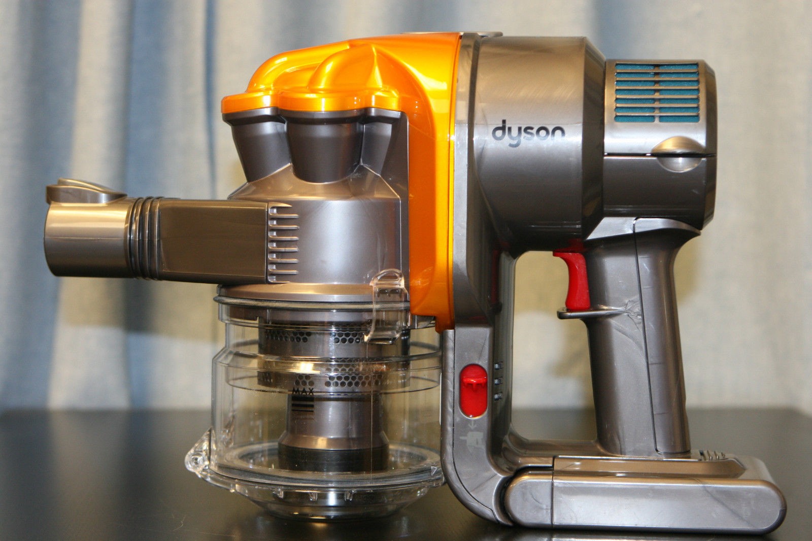
The Dyson DC16 is one of the older handheld vacuums, before the introduction of the “Digital Motor”. (Marketing obviously didn’t think “Switched Reluctance Motor” sounded quite as good).
These vacuums have a very large DC brush motor driving the suction turbine instead, the same as would be found in a cordless power tool.
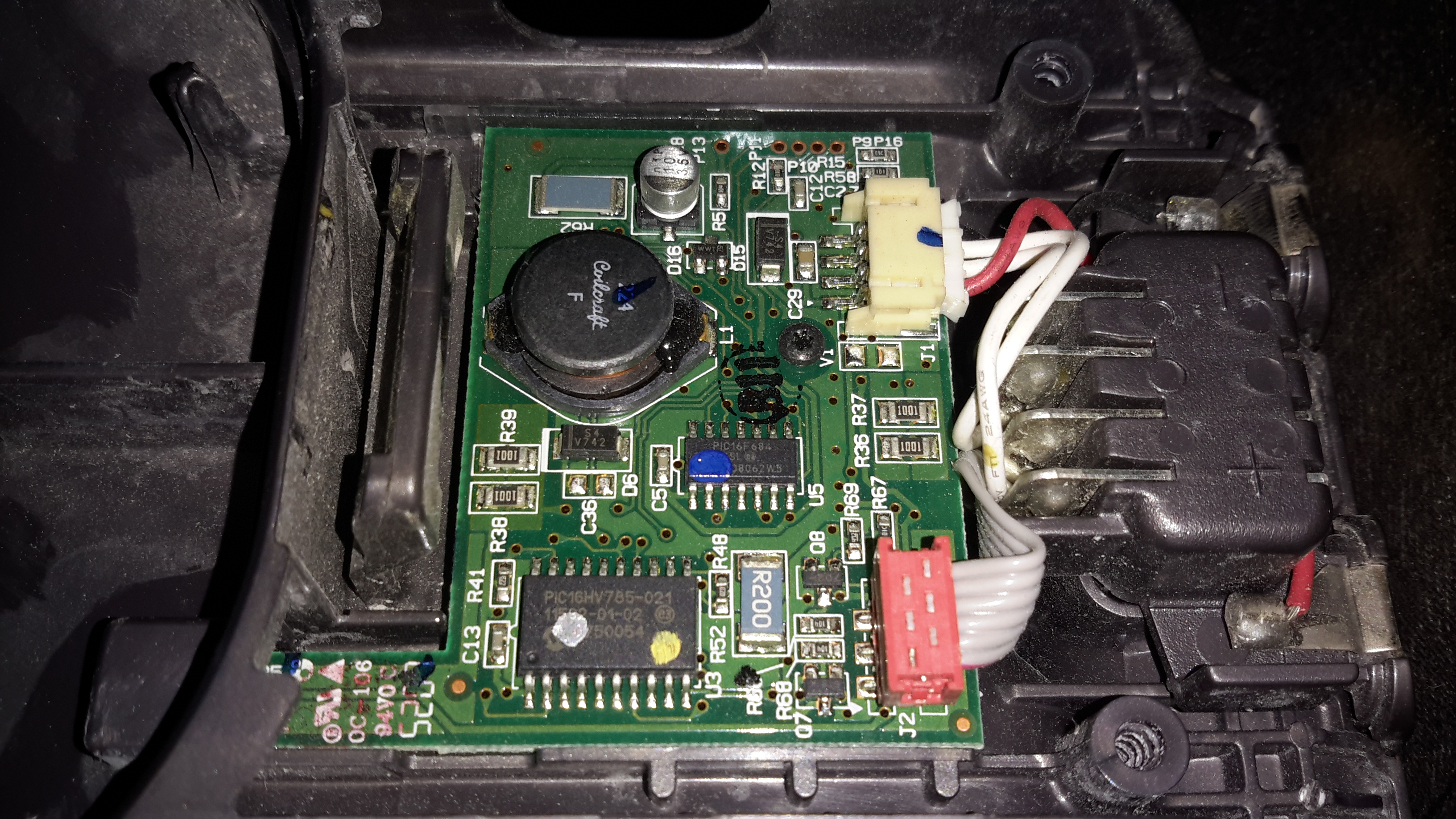
Control PCB
Popping the front cap off with the ID label, reveals the brains of the vacuum. The two large terminals at the right are for charging, which is only done at 550mA (0.5C). There are two PIC microcontrollers in here, along with a large choke, DC-DC converter for supplying the logic most likely. The larger of the MCUs, a PIC16HV785, is probably doing the soft-start PWM on the main motor, the smaller of the two, a PIC16F684 I’m sure is doing battery charging & power management. The motor has a PCB on it’s tail end, with a very large MOSFET, a pair of heavy leads connect directly from the battery connector to the motor.
Just out of sight on the bottom left edge of the board is a Hall Effect Sensor, this detects the presence of the filter by means of a small magnet, the vacuum will not start without a filter fitted.
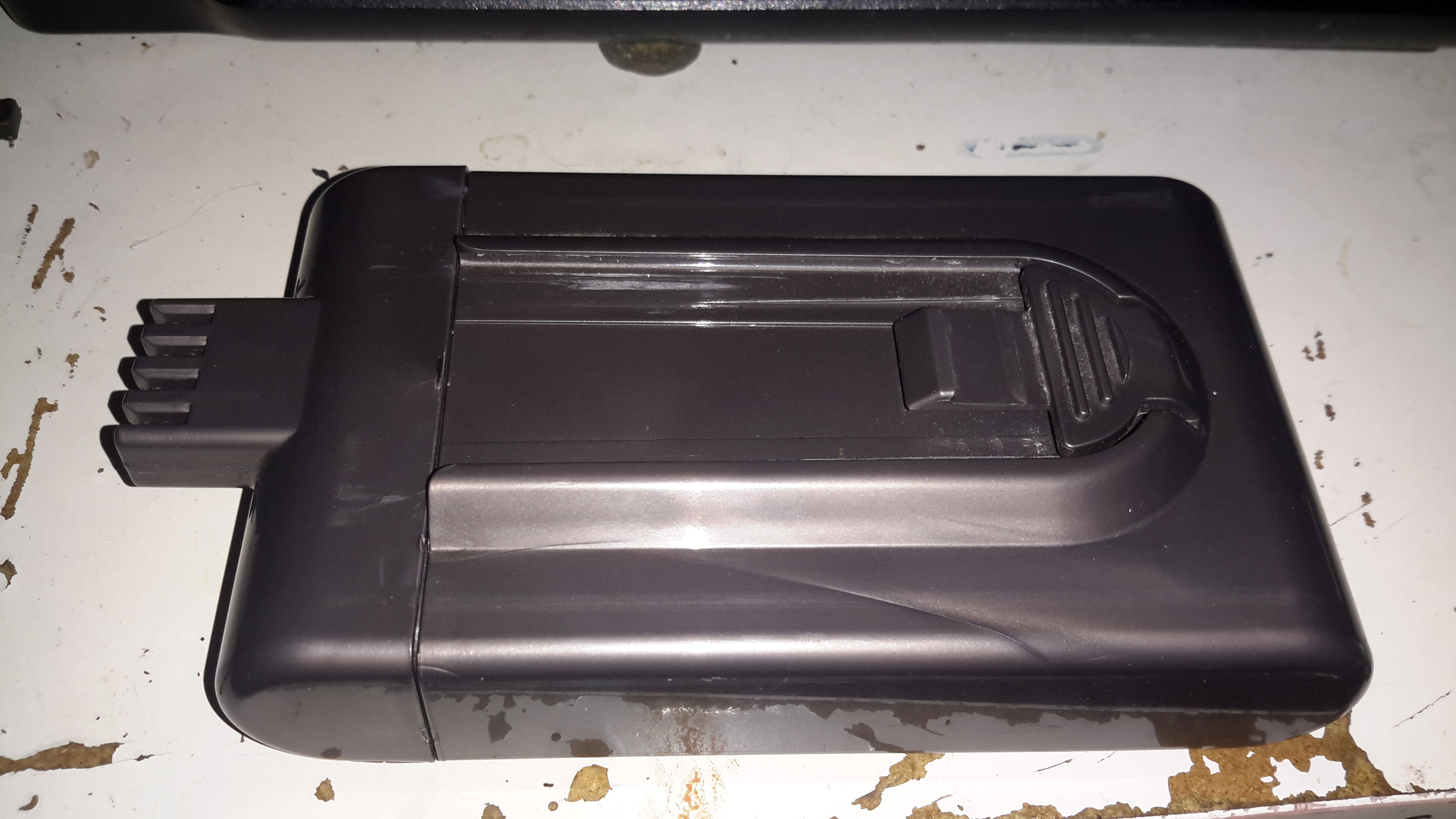
Battery Pack
The battery pack is a large custom job, obviously. 4 terminals mean there’s slightly more in here than just the cells.
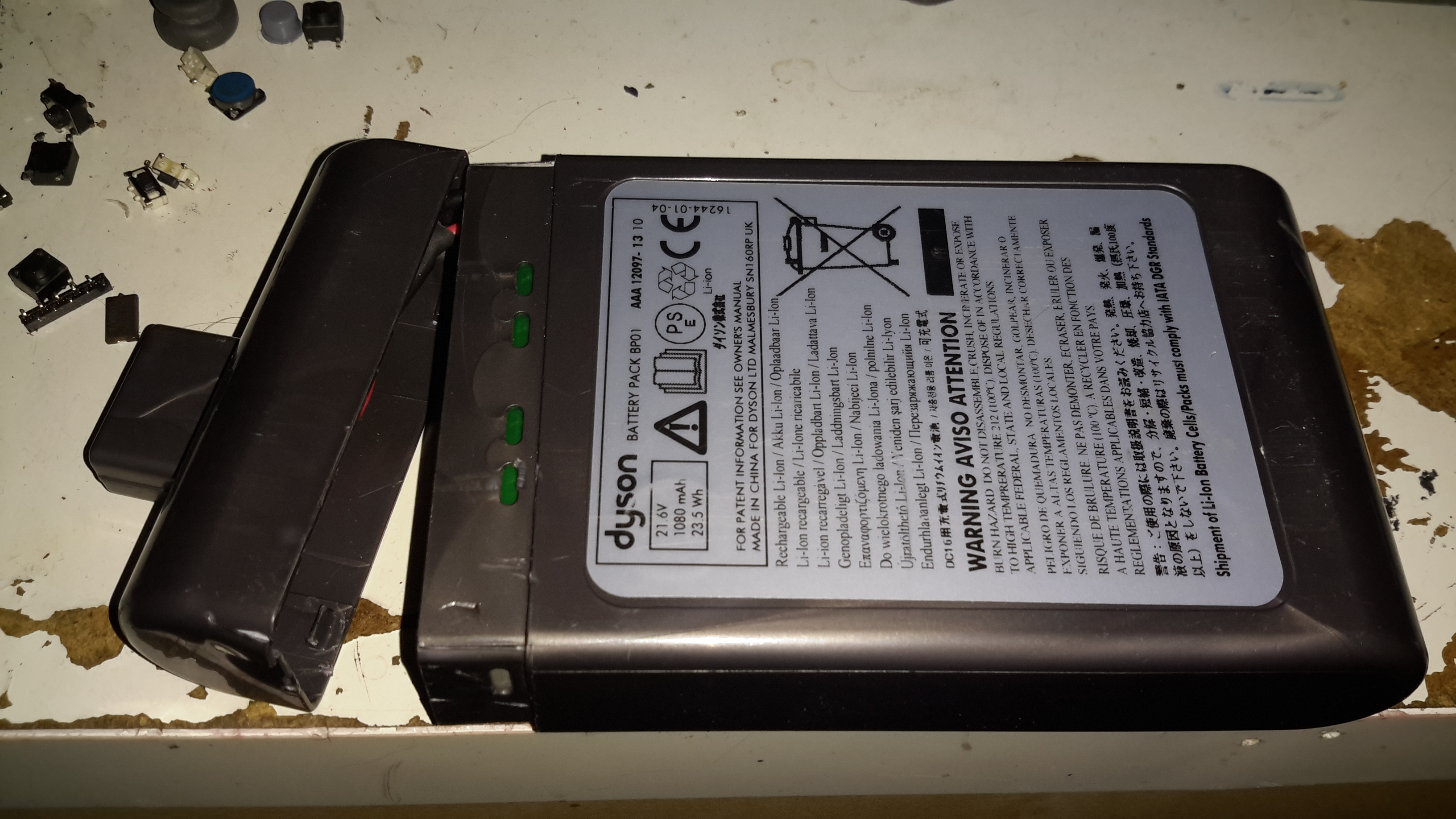
Battery Cracked
Luckily, instead of ultrasonic or solvent welding the case, these Dyson batteries are just snapped together. Some mild attack with a pair of screwdrivers allows the end cap to be removed with minimal damage.
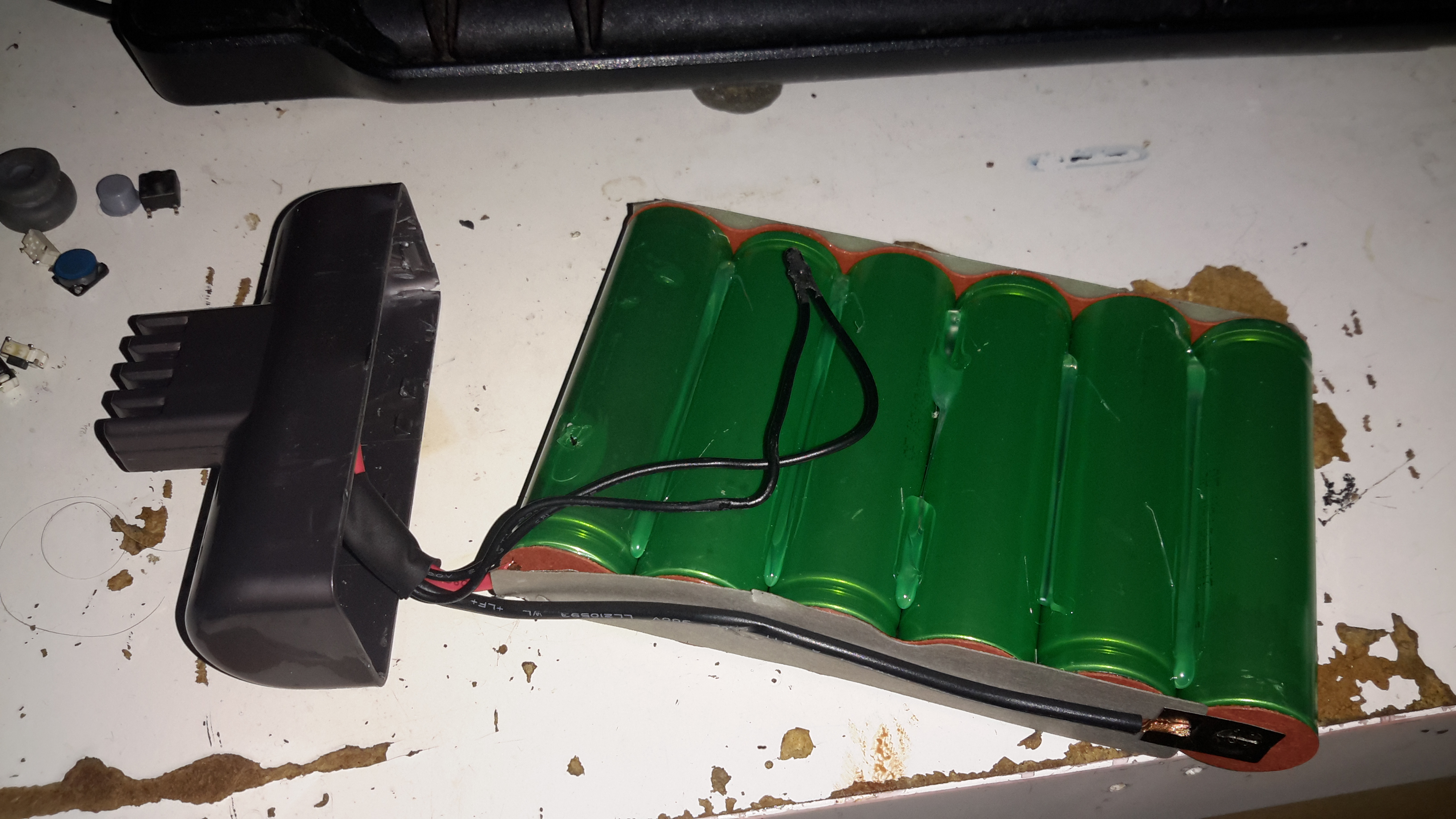
Cells
The cells were lightly hot-glued into the shell, but that can easily be solved with a drop of Isopropanol to dissolve the glue bond. The pack itself is made up of 6 Sony US18650VT High-Drain 18650 Li-Ion cells in series for 21.6v nominal. These are rated at a max of 20A discharge current, 10A charge current, and 1.3Ah capacity nominal.
There’s no intelligence in this battery pack, the extra pair of terminals are for a thermistor, so the PIC in the main body knows what temperature the pack is at – it certainly gets warm while in use due to the high current draw.
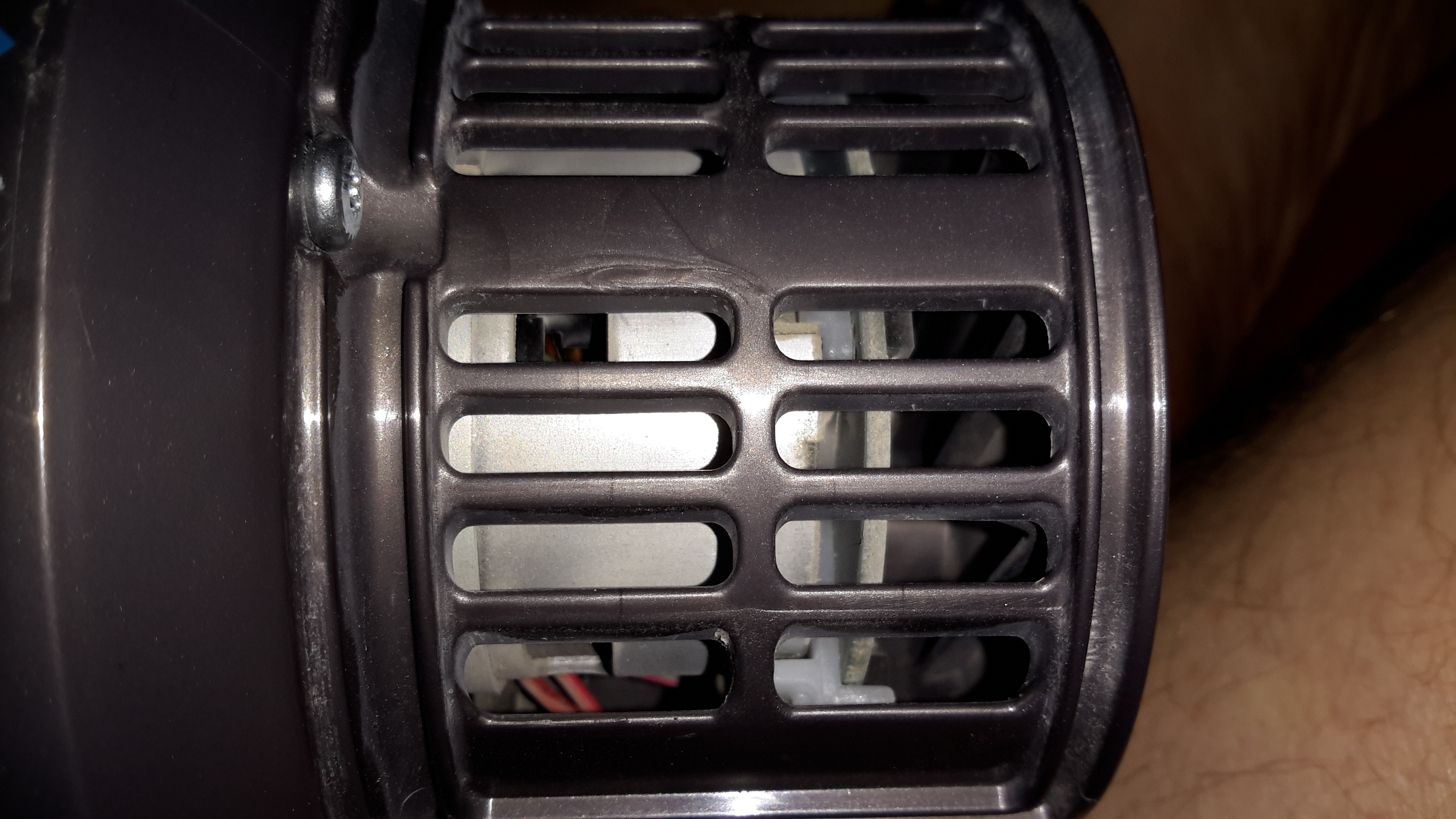
Motor
Hidden in the back side of the main body is the motor. Unfortunately I wasn’t able to get this out without doing some damage, as the wiring isn’t long enough to free the unit without some surgery.
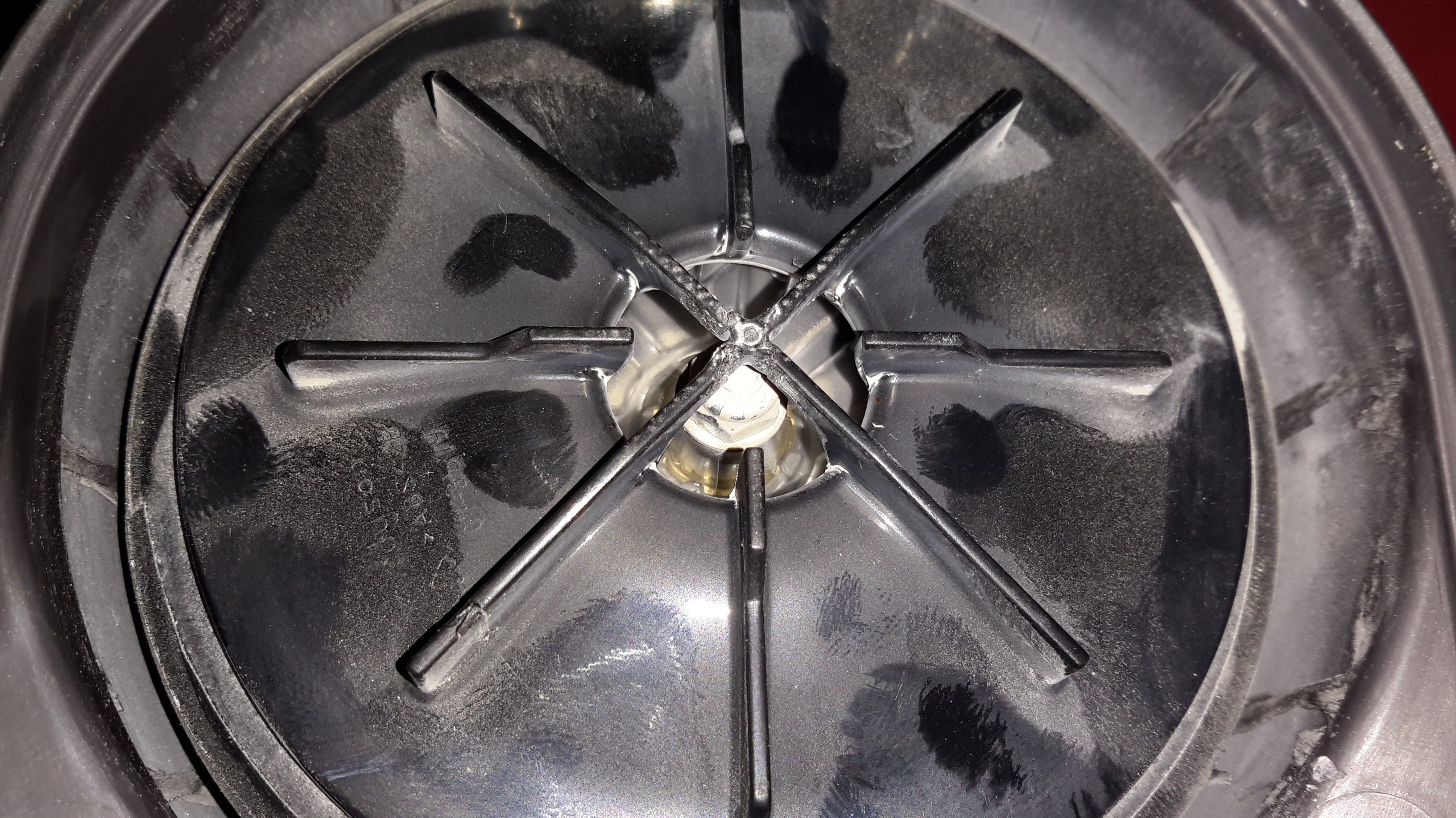
Turbine
The suction is generated by a smaller version of the centrifugal high-speed blowers used in full size vacuums. Not much to see here.
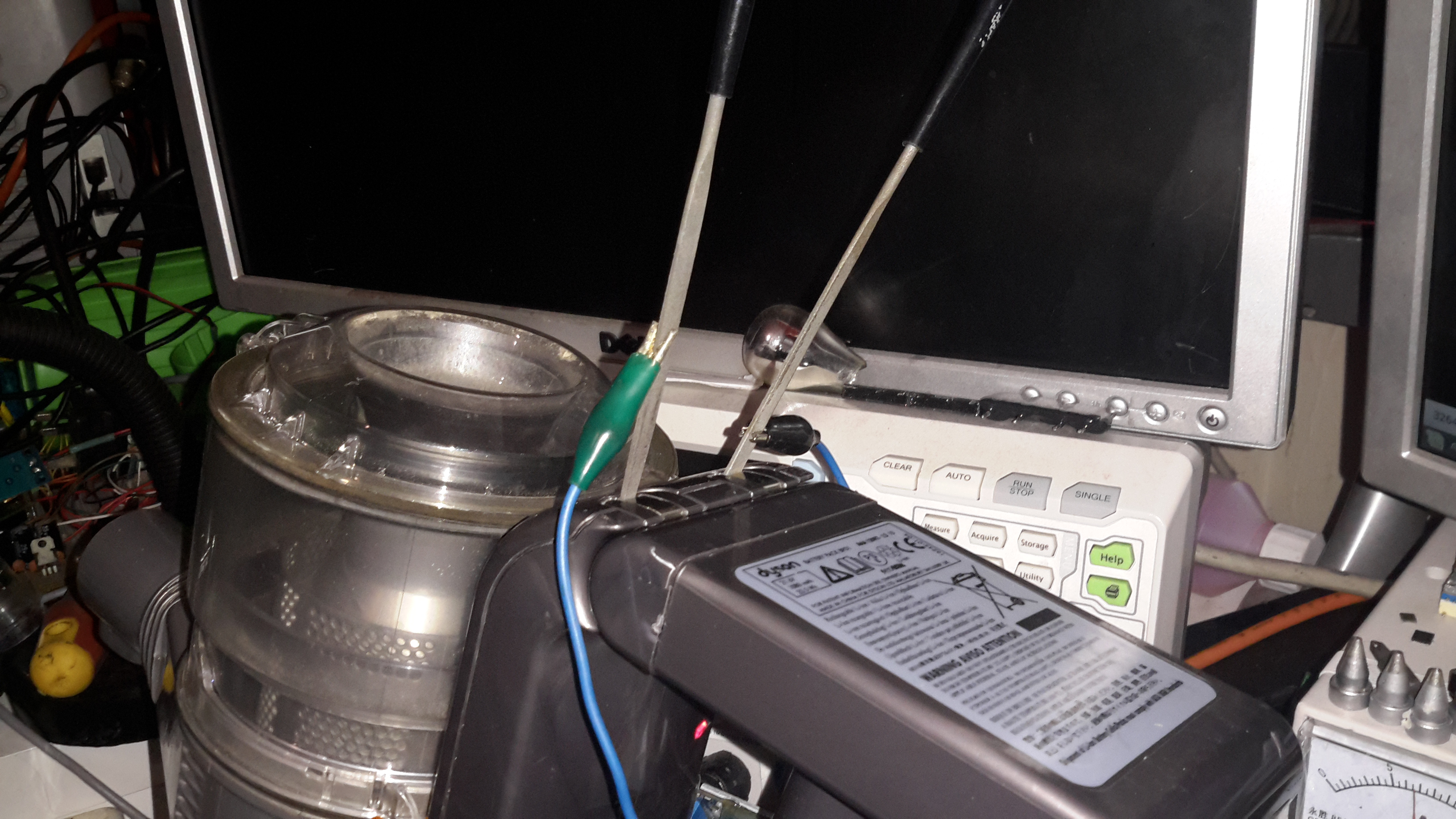
Unofficial Charger
Since I got this without a charger, I had to improvise. The factory power supply is just a 28v power brick, all the charging logic is in the vacuum itself, so I didn’t have to worry about such nasties as over-charging. I have since fitted the battery pack with a standard Li-Po balance cable, so it can be used with my ProCell charger, which will charge the pack in 35 minutes, instead of the 3 hours of the original charger.
Here is a Bosch 14.4v Professional cordless drill/driver, recovered from a skip!
It was thrown away due to a gearbox fault, which was easy to rectify.
Internals
Here is the drill with the side cover removed, showing it’s internal parts. The speed controller is below the motor & gearbox here. The unit at the top consists of a 12v DC motor, coupled to a 4-stage epicyclic gearbox unit, from which can be selected 2 different ratios, by way of the lever in the centre of the box. This disables one of the gear stages. There is a torque control clutch at the chuck end of the gearbox, this was faulty when found.
Motor
Here is the drive motor disconnected from the gearbox, having a bayonet fitting on the drive end.
Drive Gear
This is the primary drive gear of the motor, which connects with the gearbox.
Cooling Fan
The motor is cooled by this fan inside next to the commutator, drawing air over the windings.
Gearbox
This is the gearbox partially disassembled, showing the 1st & second stages of the geartrain. The second stage provides the 2 different drive ratios by having the annulus slide over the entire gearset, disabling it entirely, in high gear. The annulus gears are a potential weak point in this gearbox, as they are made from plastic, with all other gears being made of steel.
Charger
Here is the charging unit for the Ni-Cd battery packs supplied with the drill. The only indicator is the LED shown here on the front of the unit, which flashes while charging, & comes on solid when charging is complete. Charge termination is by way of temperature monitoring.
Transformer
Here the bottom of the charger has been removed, showing the internal parts. An 18v transformer supplies power to the charger PCB on the left.
Charger PCB
This is the charger PCB, with a ST Microelectronics controller IC marked 6HKB07501758. I cannot find any information about this chip.
Battery Pack Internals
Here is a battery pack with the top removed, showing the cells.
Temperature Sensor
This is the temperature sensor embedded inside the battery pack that is used by the charger to determine when charging is complete.
Another phone from the mid 90s. This is the nokia 7110.
Slider Open
Here the slider is open showing the keypad.
Battery Removed
Here the battery is removed, a Li-Ion unit.
Battery
The battery cell & protection circuit removed from the casing.
Rear Of PCB
This is the rear of the PCB removed from the housing. Data & charging ports on the right hand side f the board.
Front Of PCB
Front of the PCB with the RF sections at the left hand side & the keypad contacts on the right.
RF Sections
Closeup of the RF sections of the board, big silver rectangular cans are VCO units.
SIM Connector
Closeup of the top rear section of the PCB, with SIM cnnector, battery contacts, IR tranciever at the far left. Bottom centre is the external antenna connector.
CPU
The logic section of the board, Large chip is CPU, to right of that is the ROM storing the machine code. Other chips are unknown custom parts.
Mic & Speaker
The Mic & the loudspeaker removed from it’s housing.
LCD
LCD from the front of the unit, SPI interfaced. Flex PCB also contains the power button, loudspeaker contacts & a temperature sensor.
Scroll Wheel
The scroll wheel removed from the front housing.
Vibra-Motor
Tiny vibration motor removed from the rear housing, alerts the user to a text or phone call.
Tip Jar
If you’ve found my content useful, please consider leaving a donation by clicking the Tip Jar below!
All collected funds go towards new content & the costs of keeping the server online.