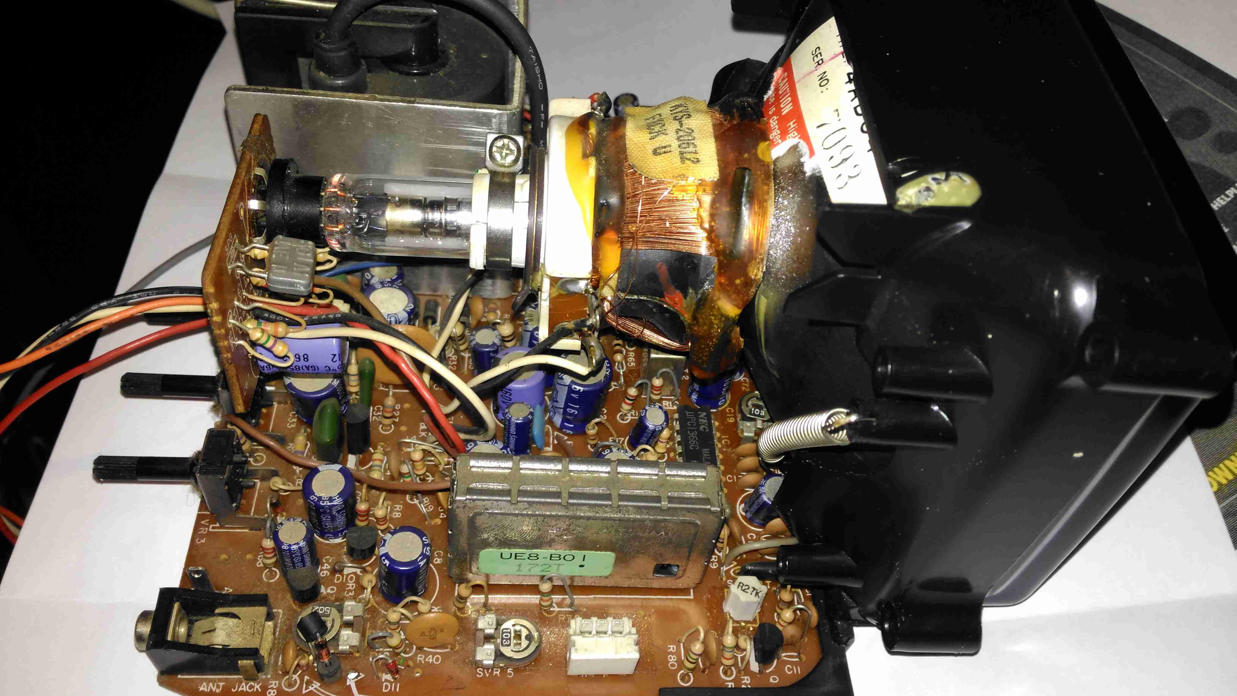
Here’s the CRT & it’s drive board removed from the main chassis. Nicely modular this unit, all the individual modules (radio, tape, TV), are separate. This is effectively a TV itself, all the tuner & IF section are onboard, unlike in other vintage units I’ve modified, where the tuner & IF has been on a separate board. There’s a 3-pin header bottom centre for the tuning potentiometer, and external antenna input jack. The internal coax for the built in antenna has been desoldered from the board here. here a the usual controls on the back for adjusting brightness, contrast & V Hold, all the other adjustments are trimmers on the PCB.
Unfortunately after 30+ years of storage, this didn’t work on first power up, neither of the oscillators for vertical or horizontal deflection would lock onto the incoming signal, but a couple of hours running seemed to improve things greatly. The numerous electrolytic capacitors in this unit were probably in need of some reforming after all this time, although out of all of them, only 21 are anything to do with the CRT itself.
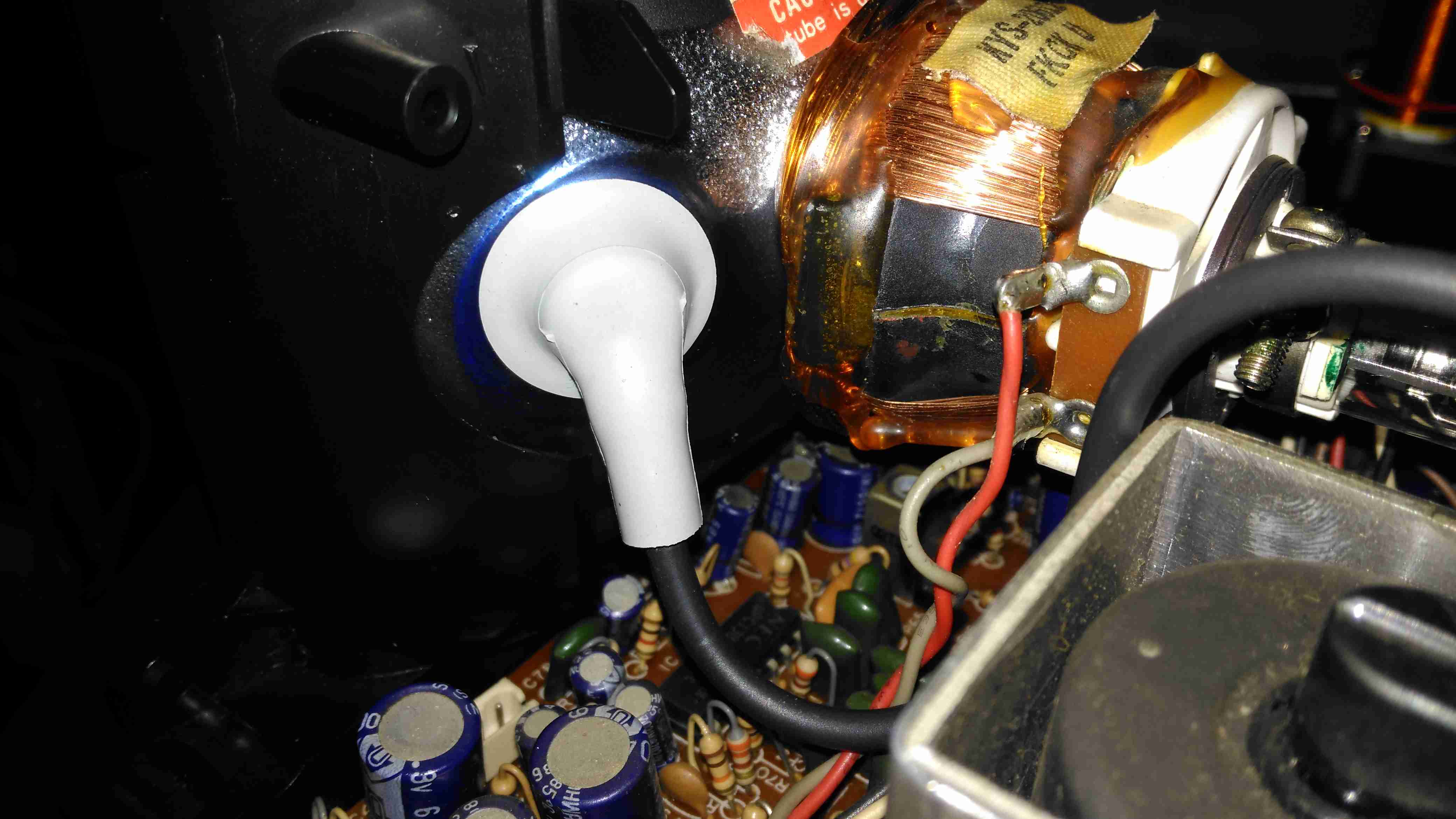
Anode Cap
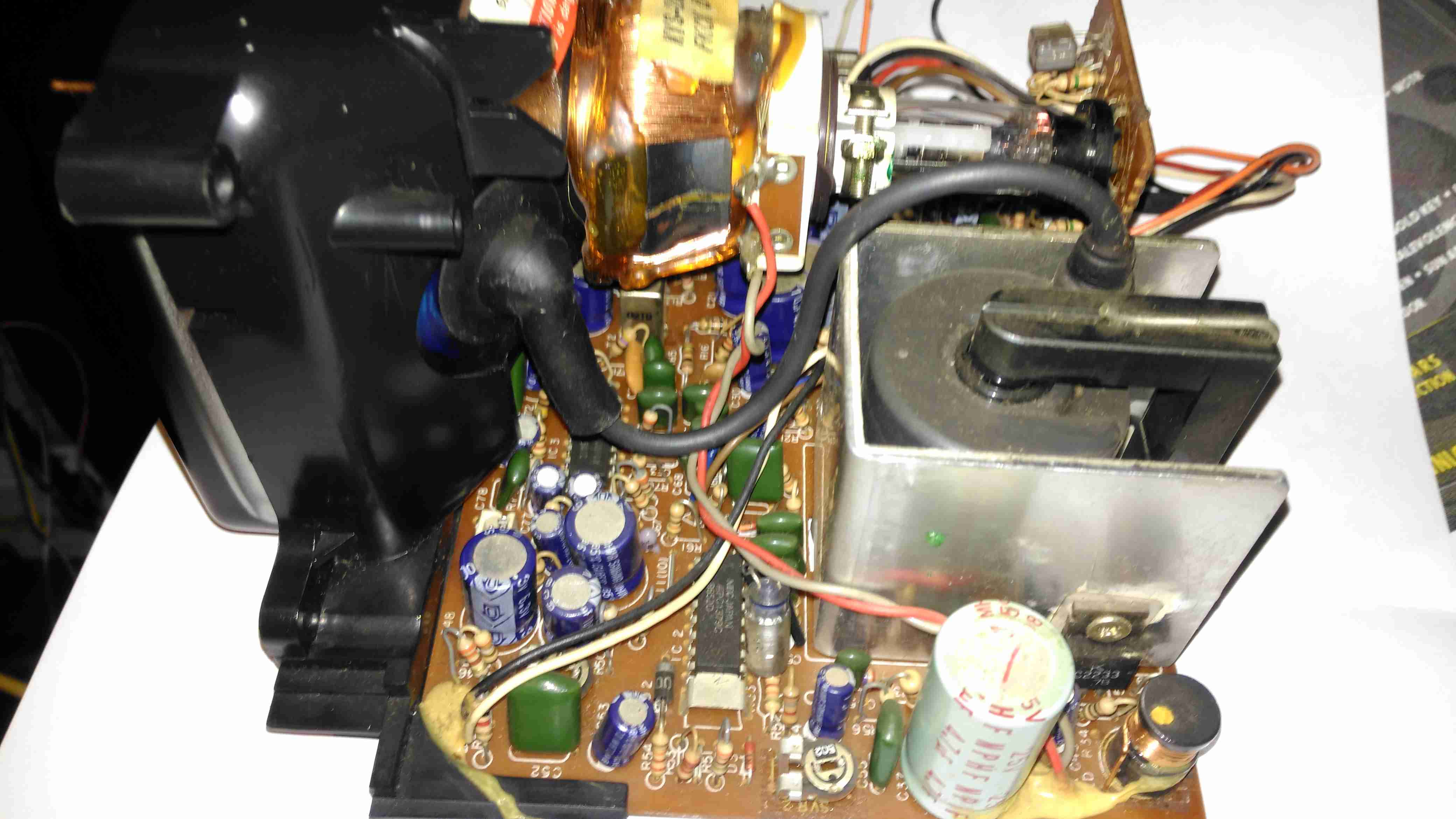
Here’s the anode side of the unit, with the small flyback transformer. The rubber anode cap has become very hard with age, so I’ll replace this with a decent silicone one from another dead TV. The Horizontal Output Transistor (a 2SC2233 NPN type) & linearity coil are visible at the bottom right corner of the board. Unfortunately, the disgusting yellow glue has been used to secure some of the wiring & large electrolytics, this stuff tends to turn brown with age & become conductive, so it has to be removed. Doing this is a bit of a pain though. It’s still a little bit flexible in places, and rock hard in others. Soaking in acetone softens it up a little & makes it easier to detach from the components.
Neck PCB
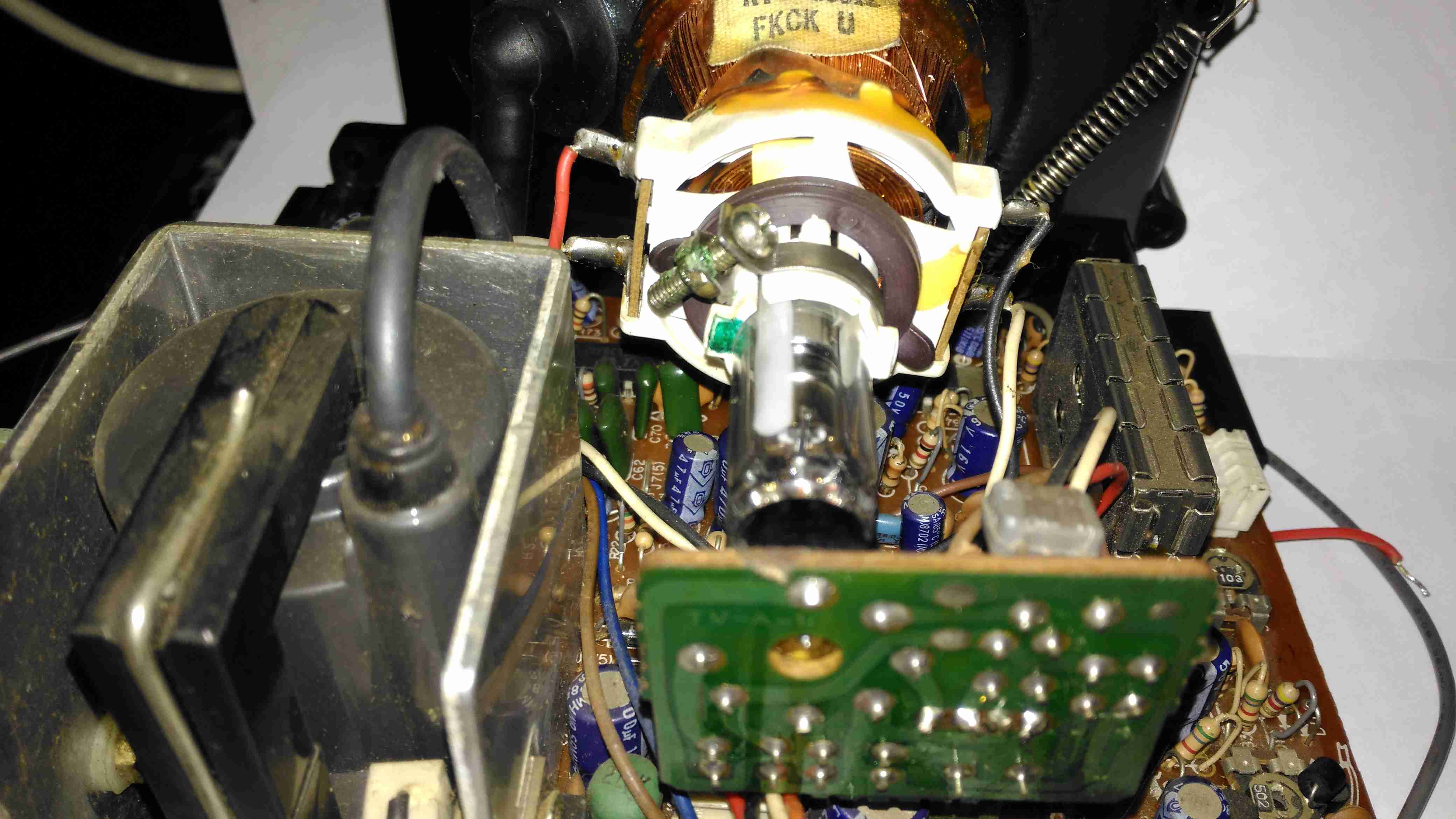
There’s little on the neck board apart from a few resistors, forming the limiting components for the video signal, and the focus divider of 1MΩ & 470KΩ feeding G3. No adjustable focus on this unit. There’s also a spark gap between the cathode line & ground, to limit the filament to cathode voltage. The flyback transformer is nestled into the heatsink used by the horizontal output transistor & a voltage regulator transistor.
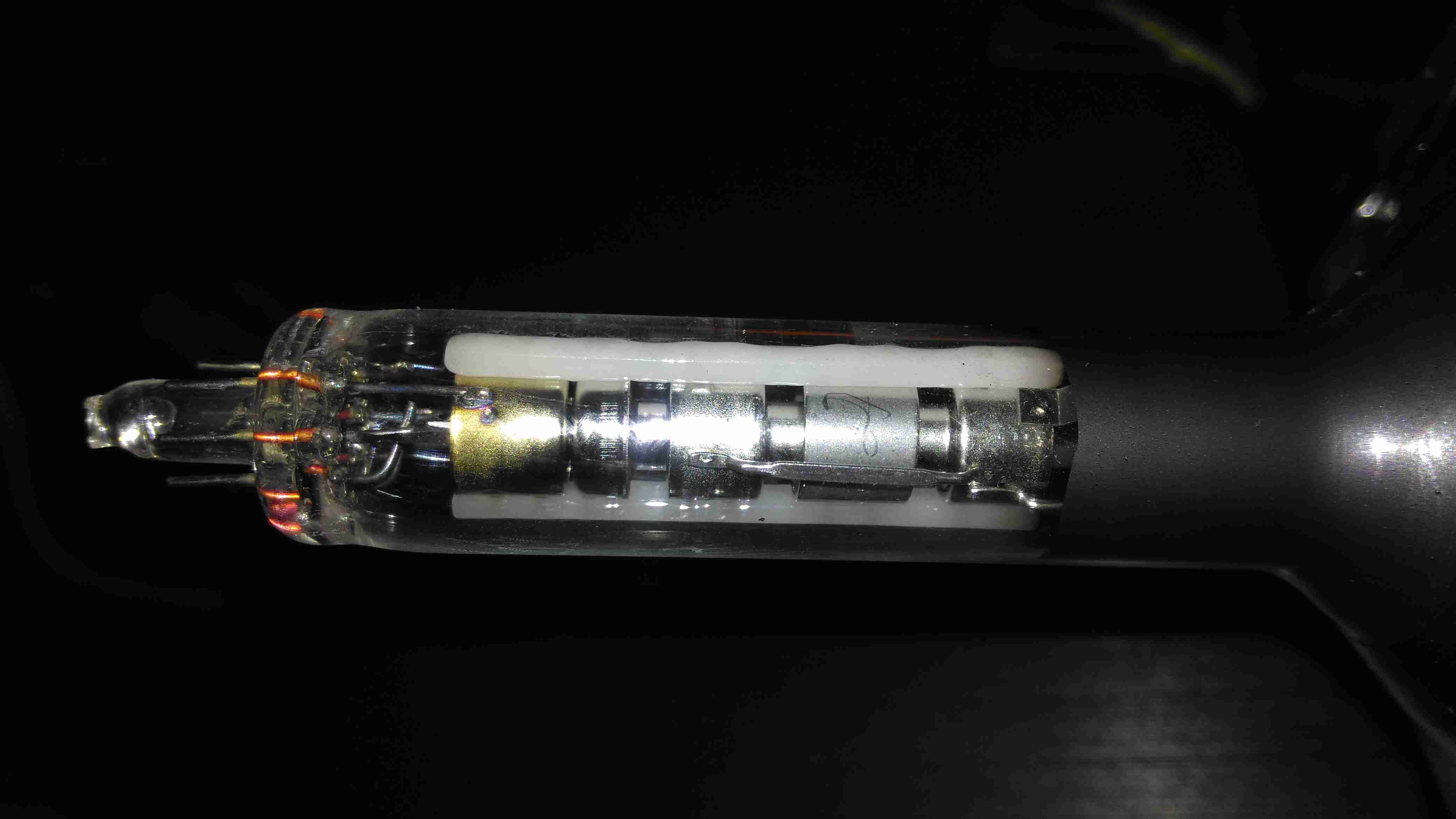
Tube Details
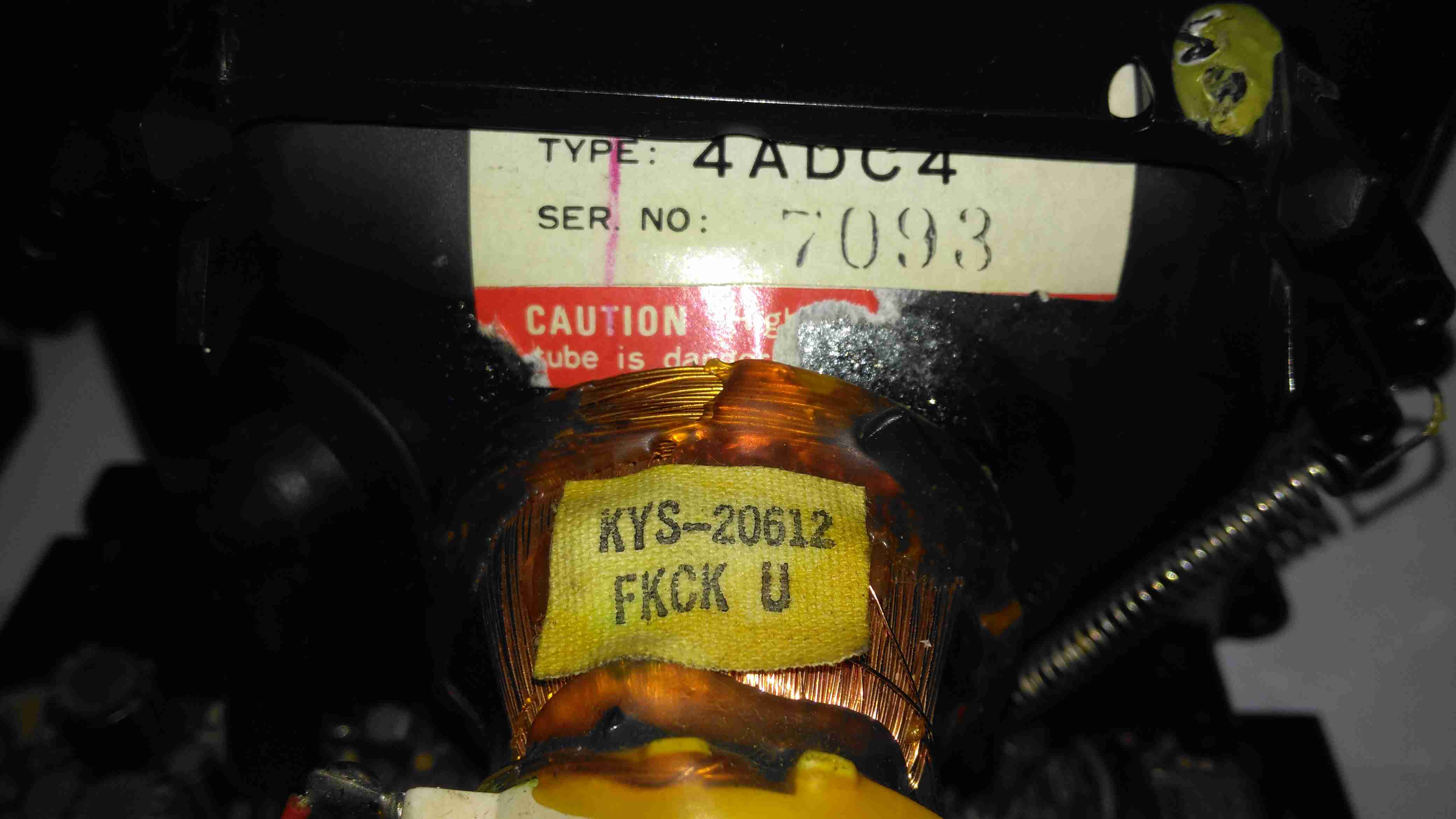
The CRT is a Samsung Electron Devices 4ADC4, with a really wide deflection angle. It’s a fair bit shorter than the Chinese CRT I have which is just a little larger, with a neck tube very thin indeed for the overall tube size.
Unusually, while the filament voltage is derived from the flyback transformer as usual, it’s rectified into DC in this unit, passing through a 1Ω resistor before the filament connection. I measured 5.3v here. The glow from the filament is barely visible even in the dark.
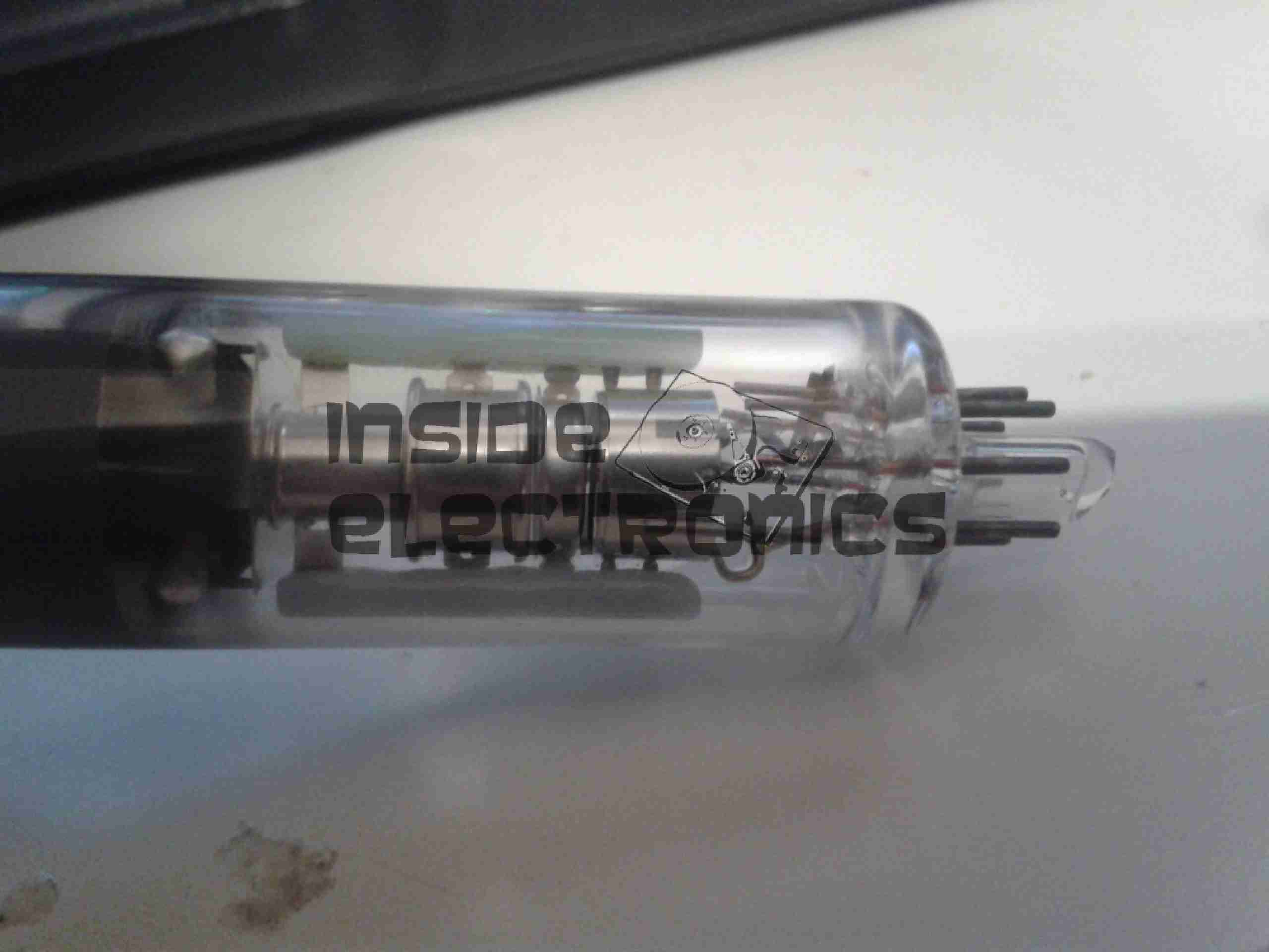
Electron Gun 1
The electron gun is the usual for a monochrome tube, with 7 pins on the seal end.
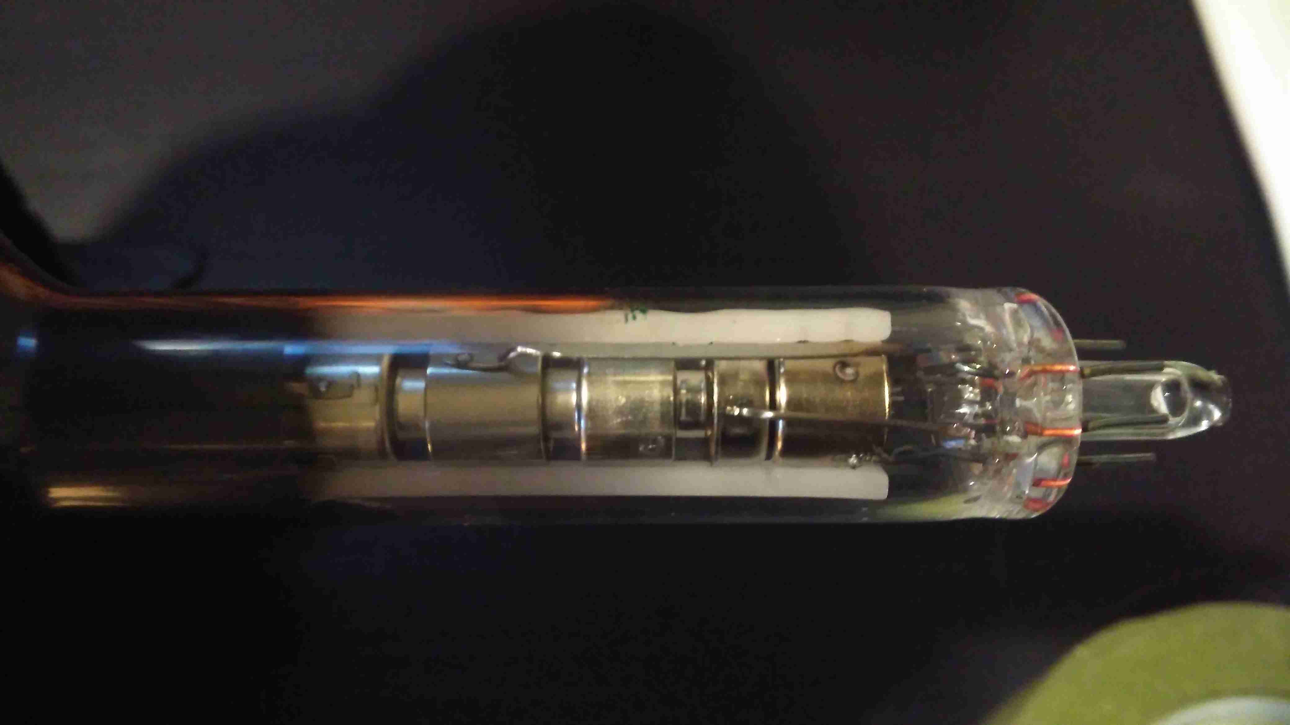
Electron Gun 2
The electrodes here from left are Final Anode, G3 (Focus Grid), Accelerating Anode, G2 (Screen Grid), G1 (Control Grid). The cathode & filament are hidden inside G1. In operation there’s about 250v on G2, and about 80v on G3.
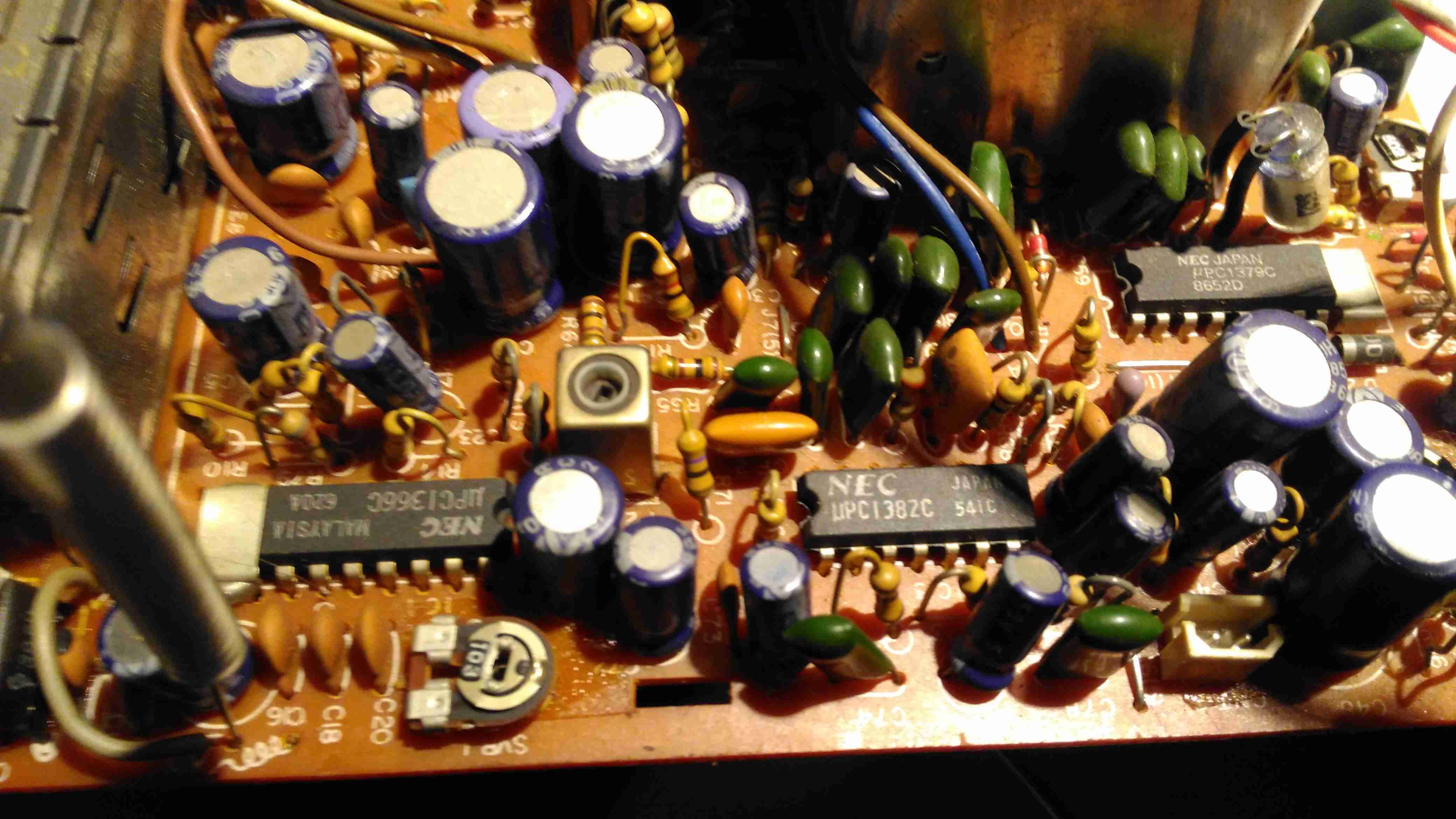
Chipset
The chipset used here is all NEC, starting with a µPC1366C Video IF Processor, which receives the IF signal from the tuner module to the left. This IC outputs the standard composite signal, and a modulated sound signal.
This then splits off to a µPC1382C Sound IF Processor & Attenuator IC, which feeds the resulting sound through the two pin header at the right bottom edge of the board to the audio amplifier in the chassis.
The composite video signal is fed through a discrete video amplifier with a single 2SC2229 transistor before going to the CRT cathode.
The remaining IC is a µPC1379C Sync Signal Processor, containing the sync separator, this is generating the required waveforms to drive the CRT deflection systems from another tap off the composite video line.
From this chip I can assume the unit was built around 1986, since this is the only date code on any of the semiconductors. Besides these 3 ICs, the rest of the circuit is all discrete components, which are well-crammed into the small board space.
There are 5 trimmer potentiometers on the board here, I’ve managed to work out the functions of nearly all of them:
SVR1: IF Gain Adjust
SVR2: H. Hold
SVR3: V. Size
SVR4: B+ Voltage Adjust
SVR5: Tuner Frequency Alignment? It’s in series with the tuning potentiometer in the chassis.
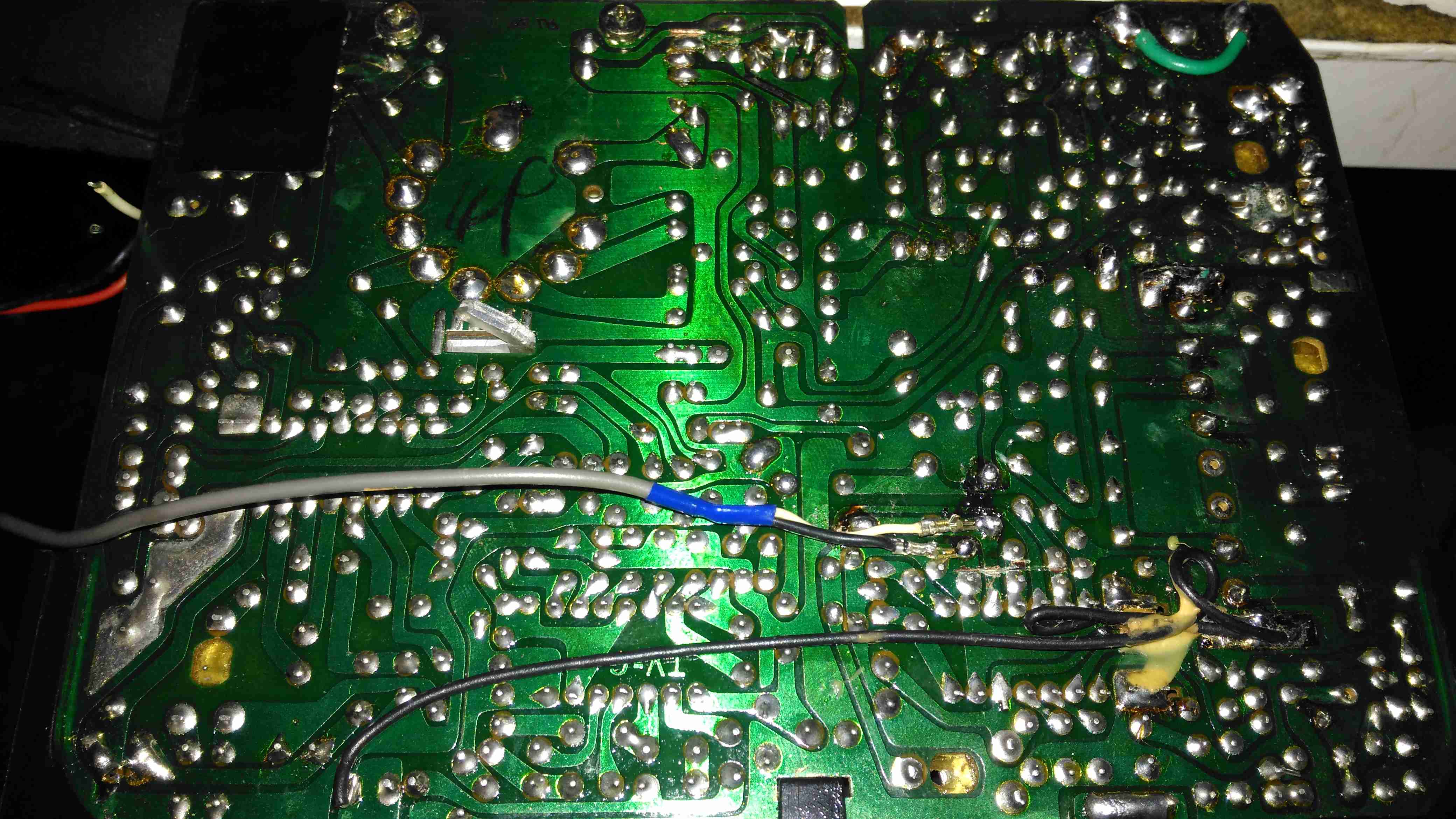
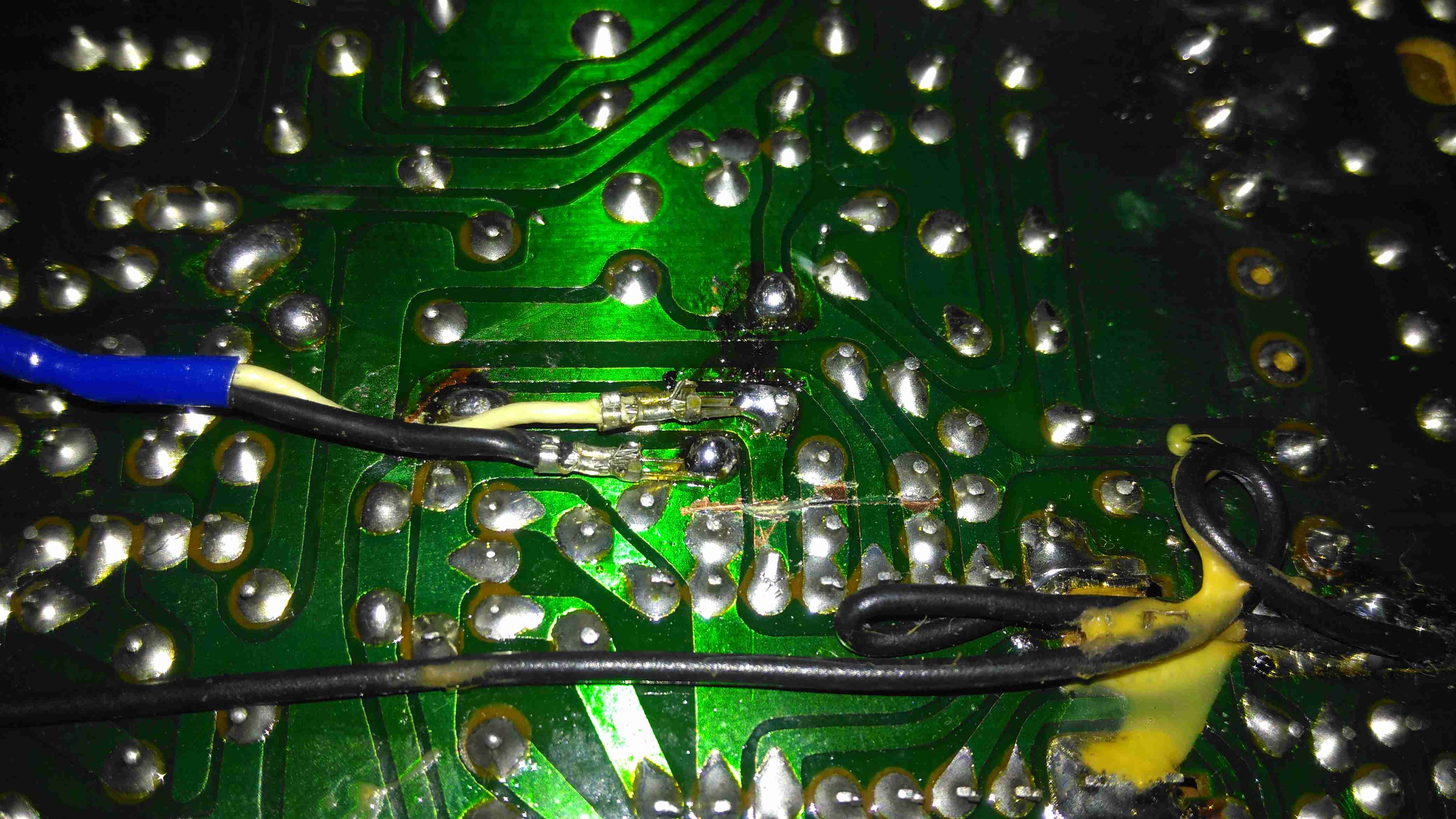
PCB Bottom
The PCB bottom shows the curved track layout typical of a hand taped out board. The soldermask is starting to flake off in places due to age, and there a couple of bodge wires completing a few ground traces. Respinning a board in those days was an expensive deal! Surprisingly, after all this time I’ve found no significant drift in the fixed resistors, but the carbon track potentiometers are drifiting significantly – 10KΩ pots are measuring as low as 8KΩ out of circuit. These will have to be replaced with modern versions, since there are a couple in timing-sensitive places, like the vertical & horizontal oscillator circuits.
Anode Cap Replaced
Here the anode cap has been replaced with a better silicone one from another TV. This should help keep the 6kV on the CRT from making an escape. This was an easy fix – pulling the contact fork out of the cap with it’s HT lead, desoldering the fork & refitting with the new cap in place.
Here I’ve replaced the important trimmers with new ones. Should help stabilize things a little.
Composite Injection Mod
Injecting a video signal is as easy as the other units. Pin 3 of the µPC1366C Video IF Processor is it’s output, so the track to Pin 3 is cut and a coax is soldered into place to feed in an external signal.
CRT In Operation
After hooking up a Raspberry Pi, we have display! Not bad after having stood idle for 30+ years.
Datasheets for the important ICs are available below:
[download id=”5690″]
[download id=”5693″]
[download id=”5696″]
Being in technology for a long time, I have seen my fair share of disk failures. However I have never seen a single instance where SMART has issued a sufficient warning to backup any data on a failing disk. The following is an example of this in action.
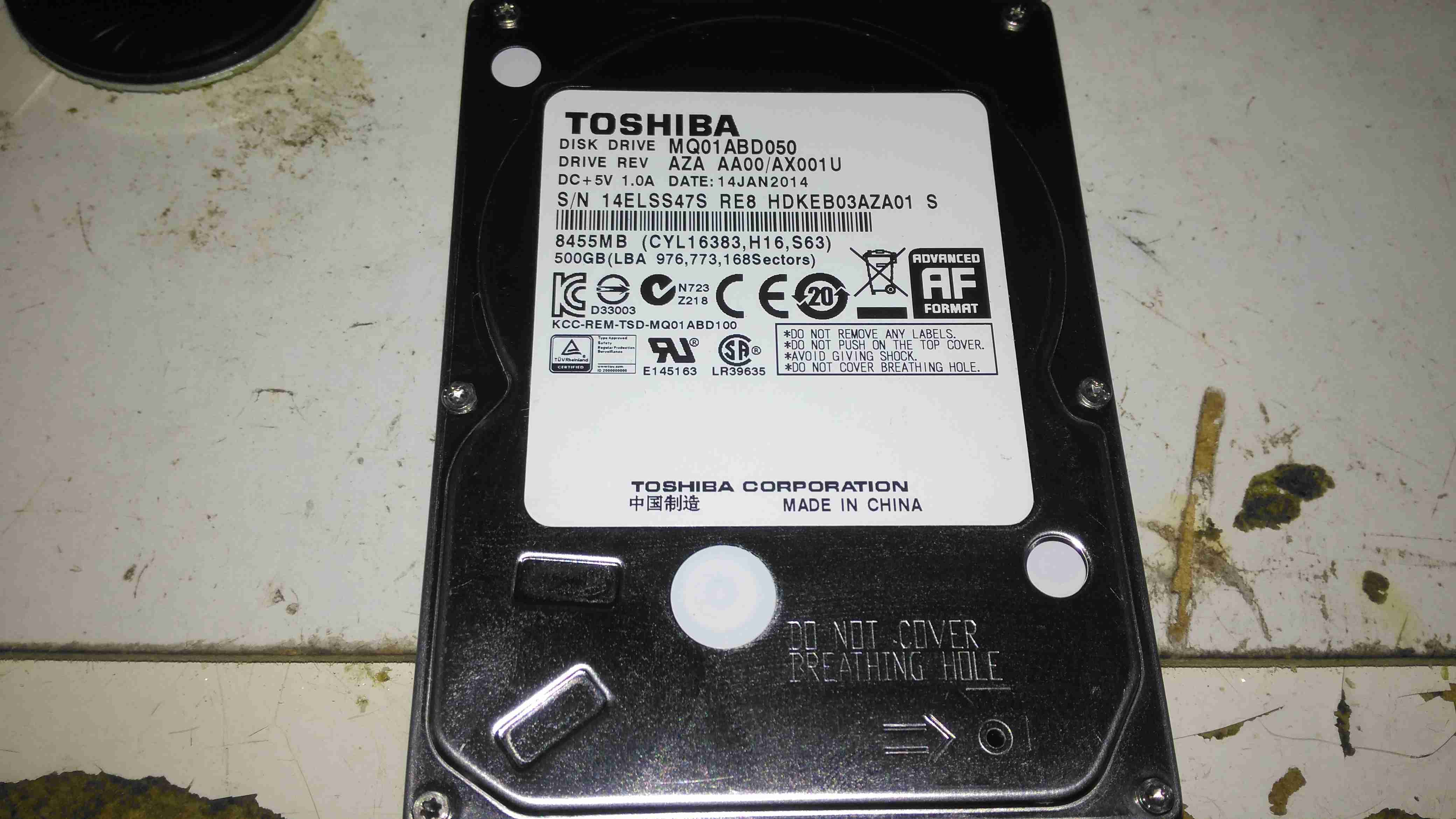
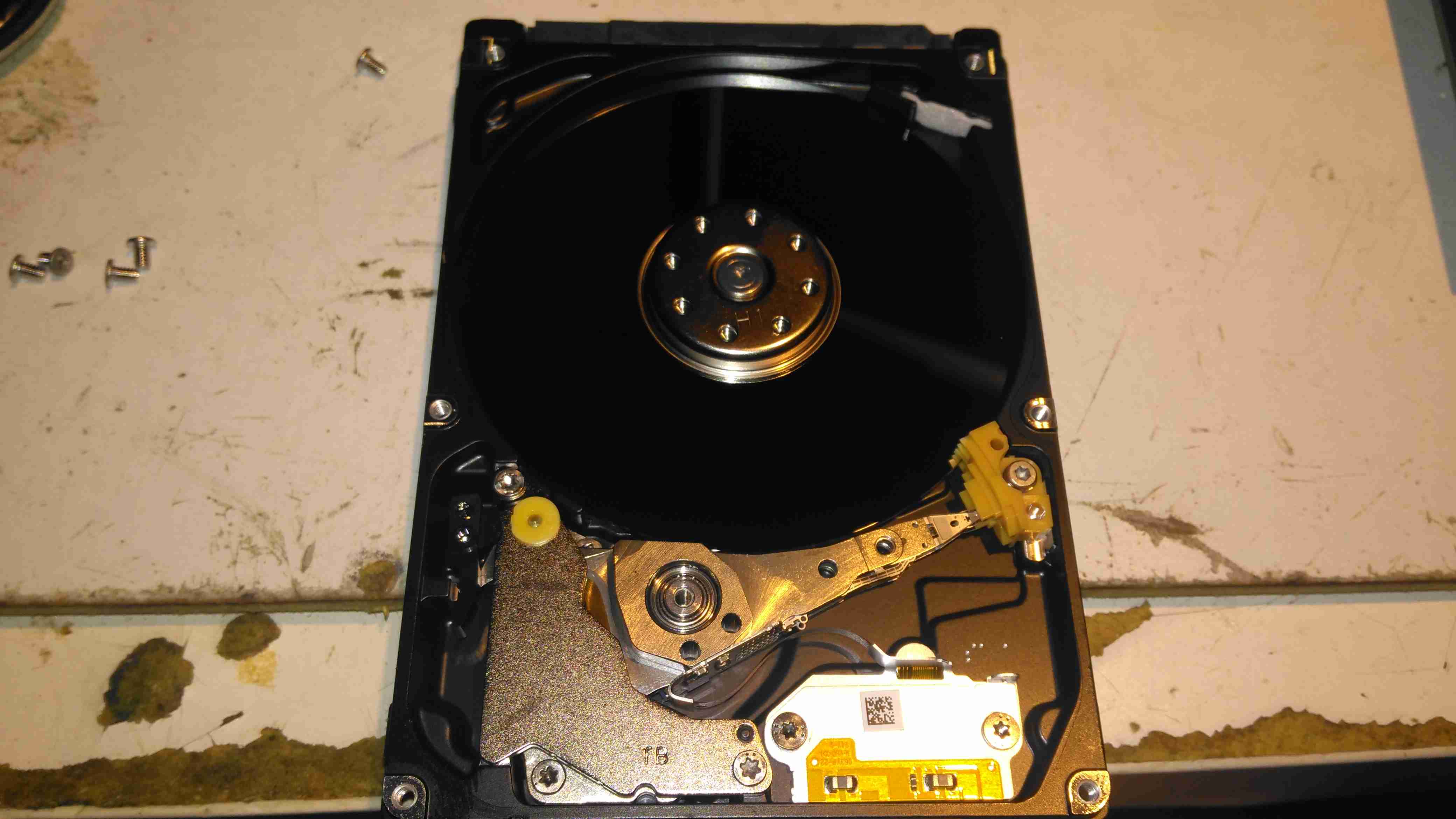
Toshiba MQ01ABD050
Here is a 2.5″ Toshiba MQ01ABD050 500GB disk drive. This unit was made in 2014, but has a very low hour count of ~8 months, with only ~5 months of the heads being loaded onto the platters, since it has been used to store offline files. This disk was working perfectly the last time it was plugged in a few weeks ago, but today within seconds of starting to transfer data, it began slowing down, then stopped entirely. A quick look at the SMART stats showed over 4000 reallocated sectors, so a full scan was initiated.
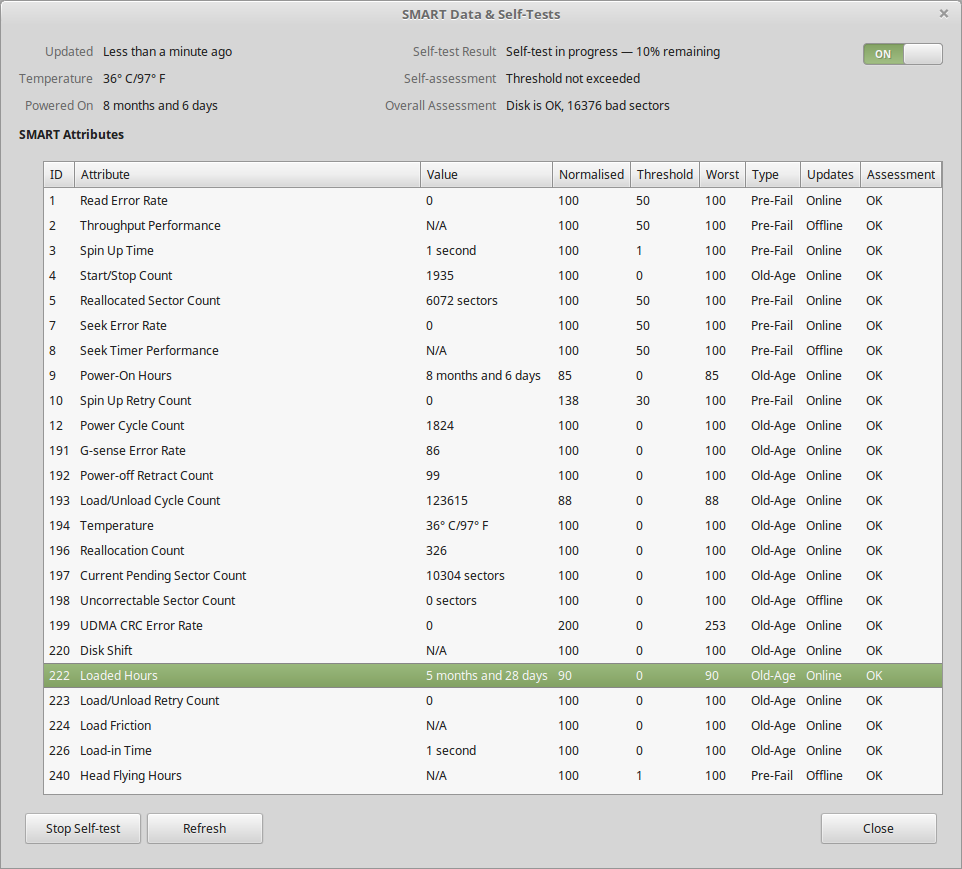
SMART Test Failure
After the couple of hours an extended test takes, the firmware managed to find a total of 16,376 bad sectors, of which 10K+ were still pending reallocation. Just after the test finished, the disk began making the usual clicking sound of the head actuator losing lock on the servo tracks. Yet SMART was still insisting that the disk was OK! In total about 3 hours between first power up & the disk failing entirely. This is possibly the most sudden failure of a disk I’ve seen so far, but SMART didn’t even twig from the huge number of sector reallocations that something was amiss. I don’t believe the platters are at fault here, it’s most likely to be either a head fault or preamp failure, as I don’t think platters can catastrophically fail this quickly. I expected SMART to at least flag that the drive was in a bad state once it’s self-test completed, but nope.
Internals
After pulling the lid on this disk, to see if there’s any evidence of a head crashing into a platter, there’s nothing – at least on a macroscopic scale, the single platter is pristine. I’ve seen disks crash to the point where the coating has been scrubbed from the platters so thoroughly that they’ve been returned to the glass discs they started off as, with the enclosure packed full of fine black powder that used to be data layer, but there’s no indication of mechanical failure here. Electronic failure is looking very likely.
Clearly, relying on SMART to alert when a disk is about to take a dive is an unwise idea, replacing drives after a set period is much better insurance if they are used for critical applications. Of course, current backups is always a good idea, no matter the age of drive.
During the rebuild of the wheelchair motors for the support trolley, I found myself needing an accurate milliohm meter to test the armature windings with. Commercial instruments like these are expensive, but some Google searching found a milliohm meter project based around the Arduino from Circuit Cellar.
Circuit Diagram
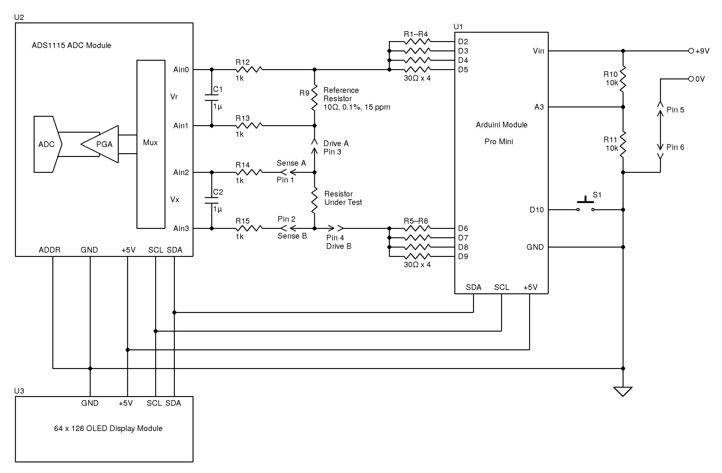
Here’s the original author’s circuit diagram, paralleling nearly all of the Arduino’s digital output pins together to source/sink the test current, an ADS1115 ADC to take more accurate readings, with the results displayed on a jellybean 128×64 OLED module. The most expensive part here is the 10Ω 0.1% 15ppm reference resistor, R9.
I decided to make some small adjustments to the power supply section of the project, to include a rechargeable lithium cell rather than a 9v PP3 battery. This required some small changes to the Arduino sketch, a DC-DC boost converter to supply 5v from the 3.7v of a lithium cell, a charger module for said cell, and with the battery voltage being within the input range of the analogue inputs, the voltage divider on A3 was removed. A new display icon was also added in to indicate when the battery is being charged, this uses another digital input pin for input voltage sensing.
I also made some basic changes to the way an unreadable resistance is displayed, showing “OL” instead of “—–“, and the meter sends the reading out over the I²C bus, for future expansion purposes. The address the data is directed to is set to 0x50.
I’ve not etched a PCB for this as I couldn’t be bothered with the messy etchant, so I built this on a matrix board instead.
Final Prototype
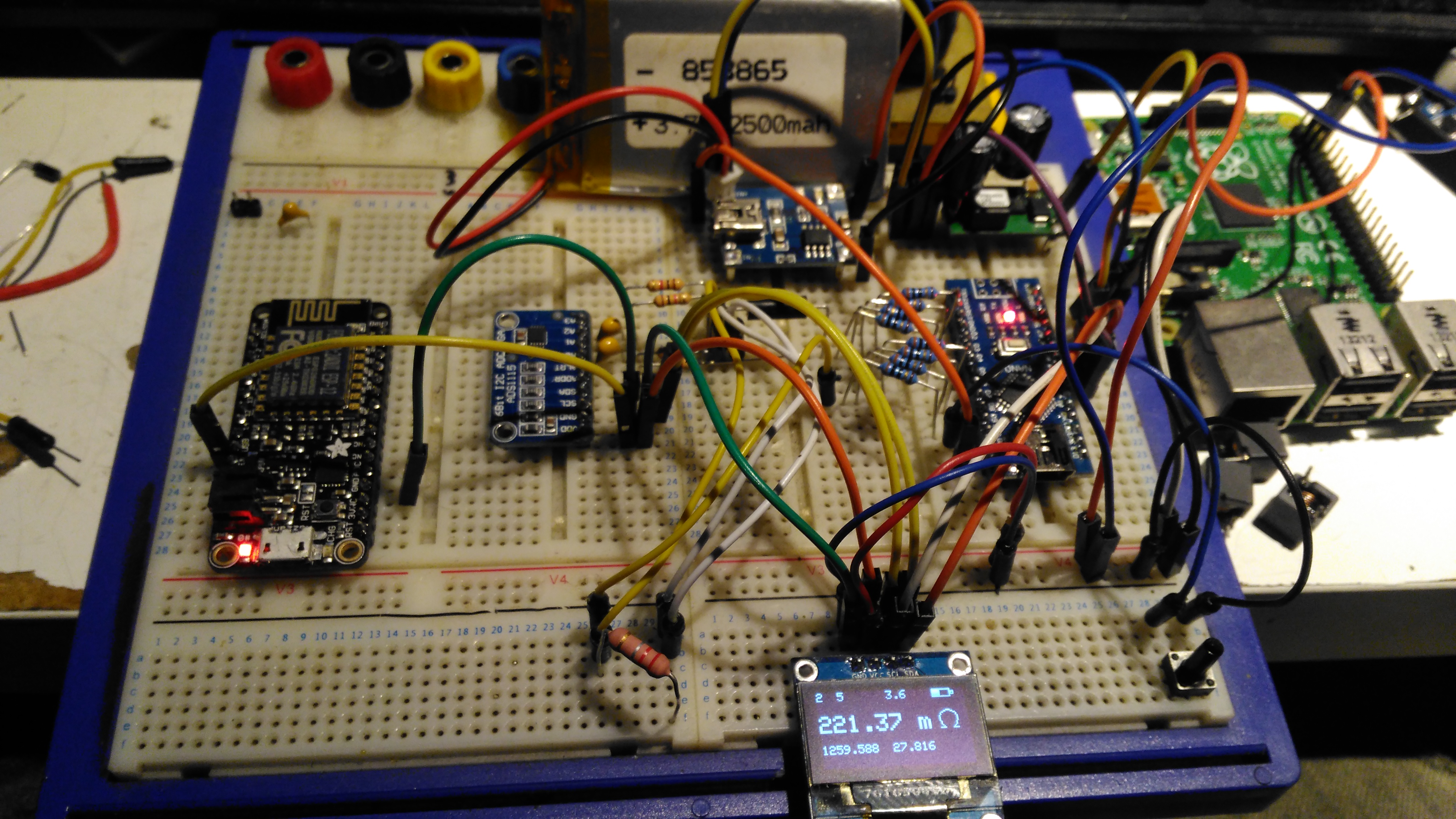
Since I made some changes to both the software and the hardware components, I decided to prototype the changes on breadboard. The lithium cell is at the top of the image. with the charger module & DC-DC converter. The Arduino Nano is on the right, the ADC & reference resistor on the left, and the display at the bottom.
The Raspberry Pi & ESP8266 module are being used in this case to discharge the battery quicker to make sure the battery level calibration was correct, and to make sure the DC-DC converter would continue to function throughout the battery voltage range.
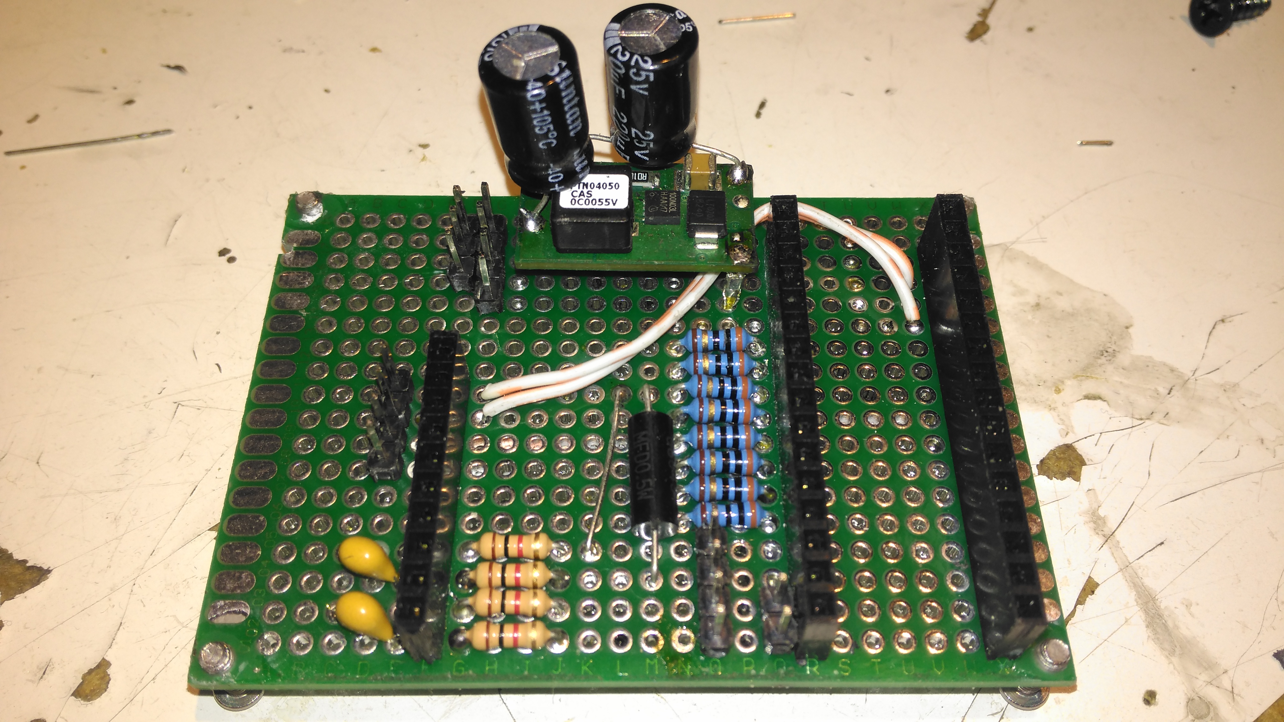
Matrix Board Passives
Here’s the final board with the passive components installed, along with the DC-DC converter. I used a Texas Instruments PTN04050 boost module for power as I had one spare.
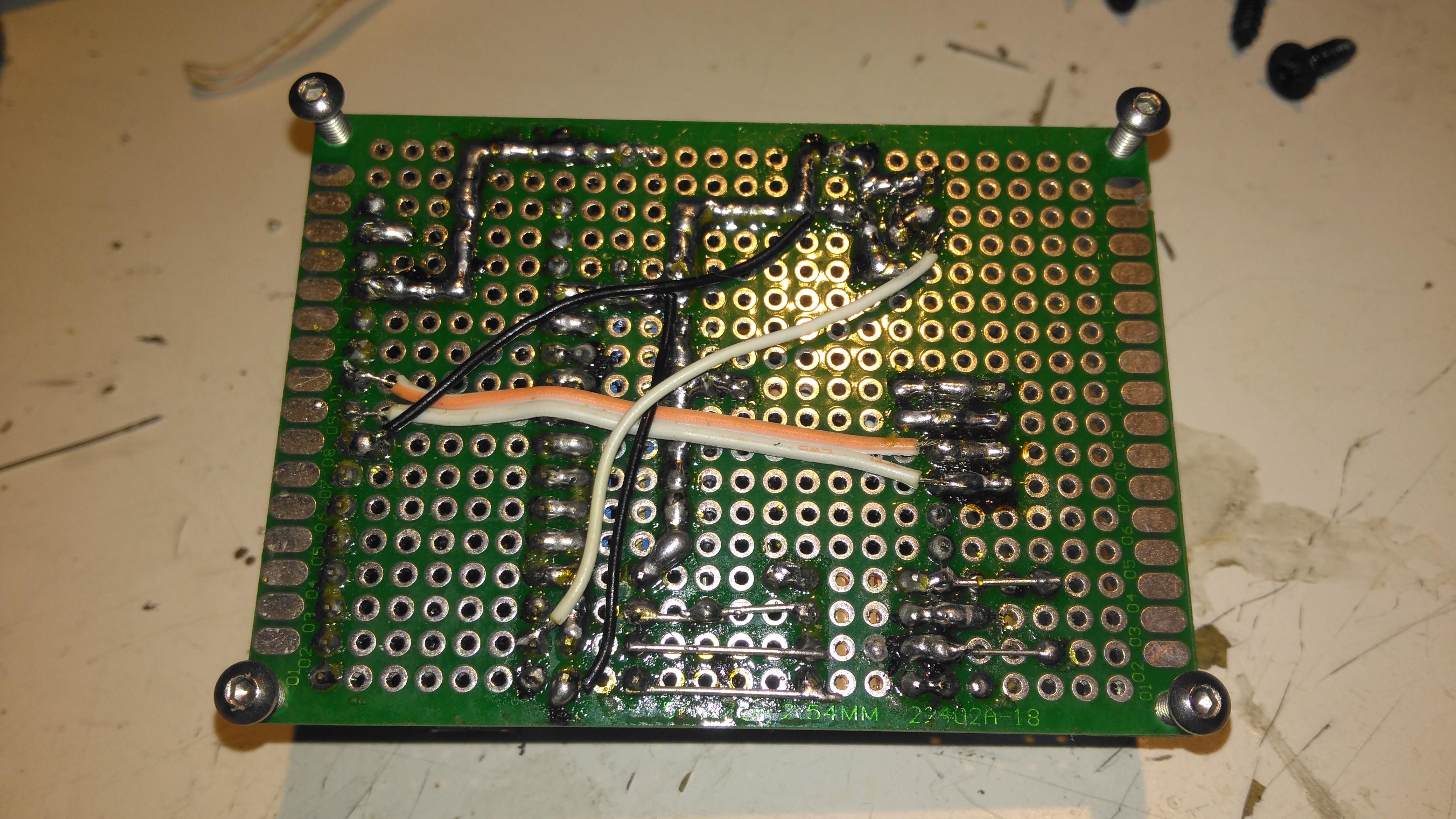
Matrix Board Rear
The bottom of the board has most of the wire jumpers for the I²C bus, and power sensing.
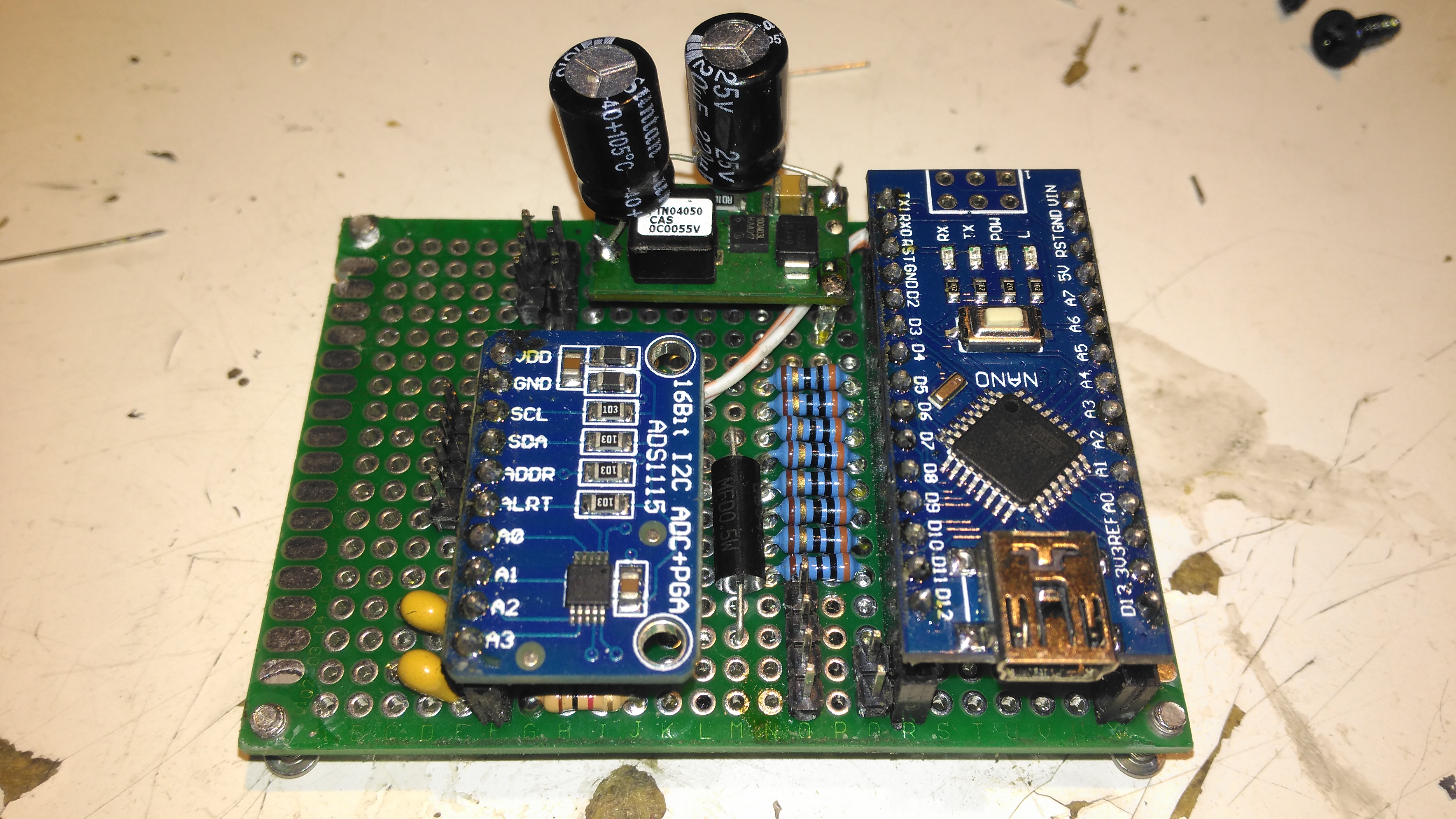
Matrix Board Modules
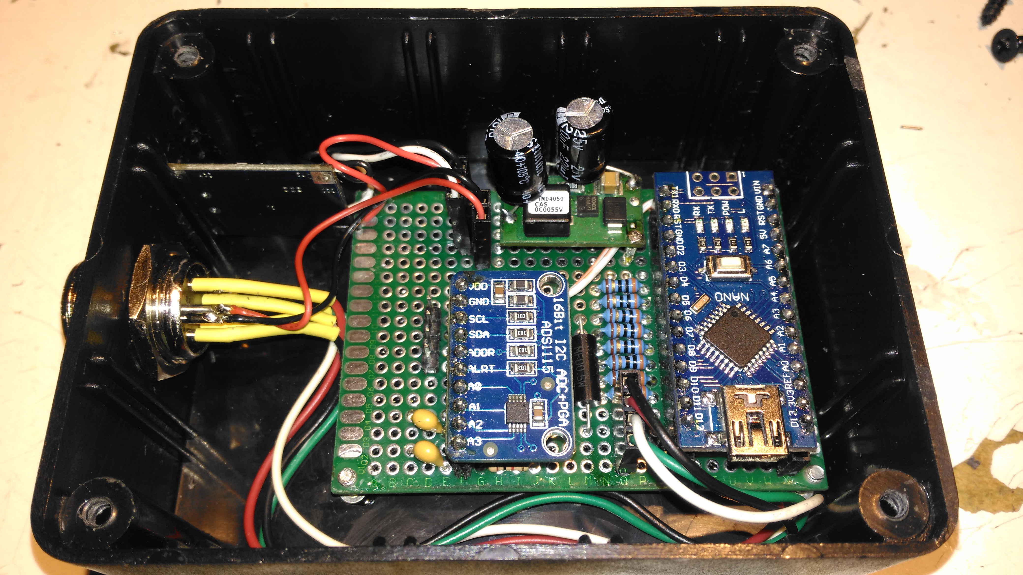
Here’s both modules installed on the board. I used an Arduino Nano instead of the Arduino Pro Mini that the original used as these were the parts I had in stock. Routing the analogue pins is also easier on the Mini, as they’re brought out to pins in the DIP footprint, instead of requiring wire links to odd spots on the module. To secure the PCB into the case without having to drill any holes, I tapped the corner holes of the matrix board M2.5 & threaded cap head screws in. These are then spot glued to the bottom of the case to secure the finished board.
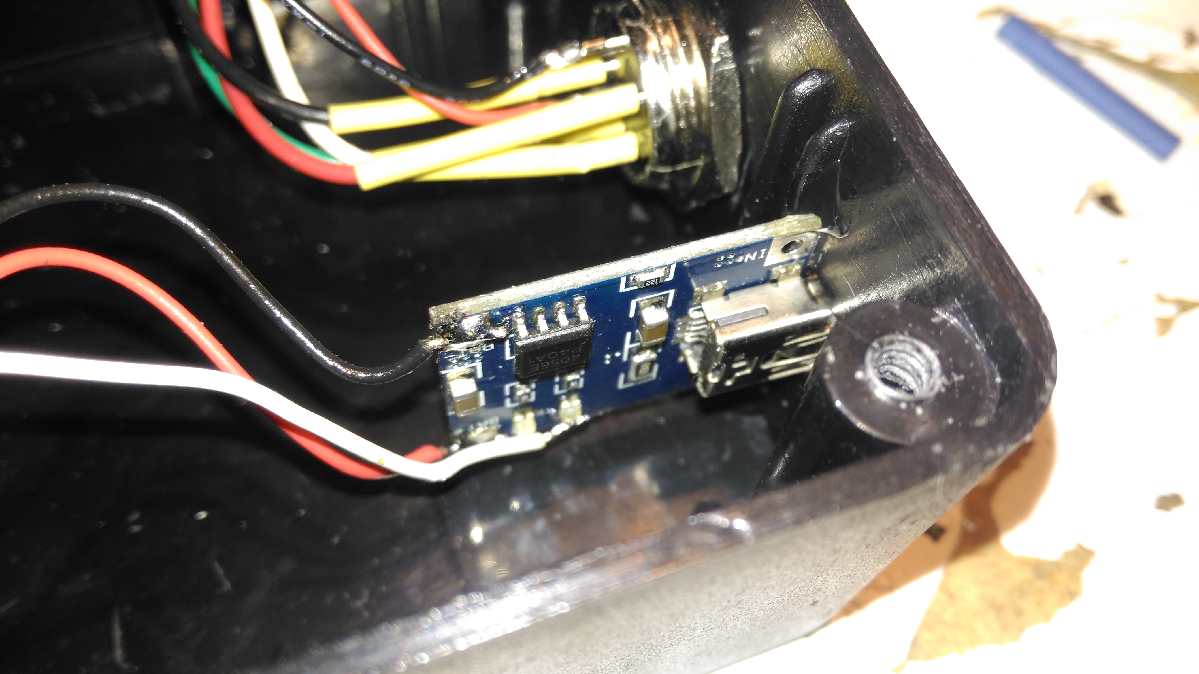
Lithium Charger
The lithium charger module is attached to the side of the enclosure, the third white wire is for input sensing – when the USB cable is plugged in a charge icon is shown on the OLED display.
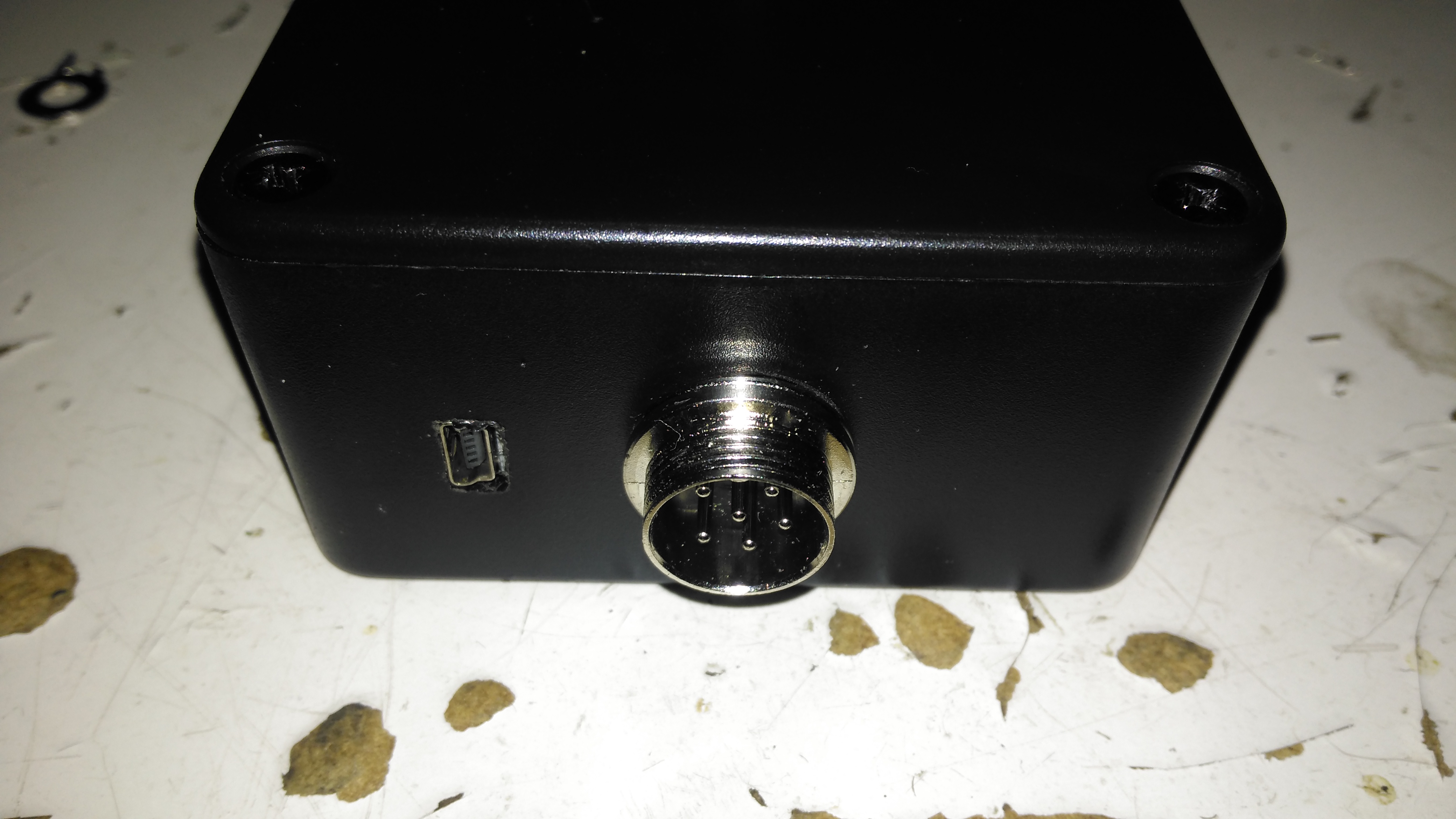
Input Connections
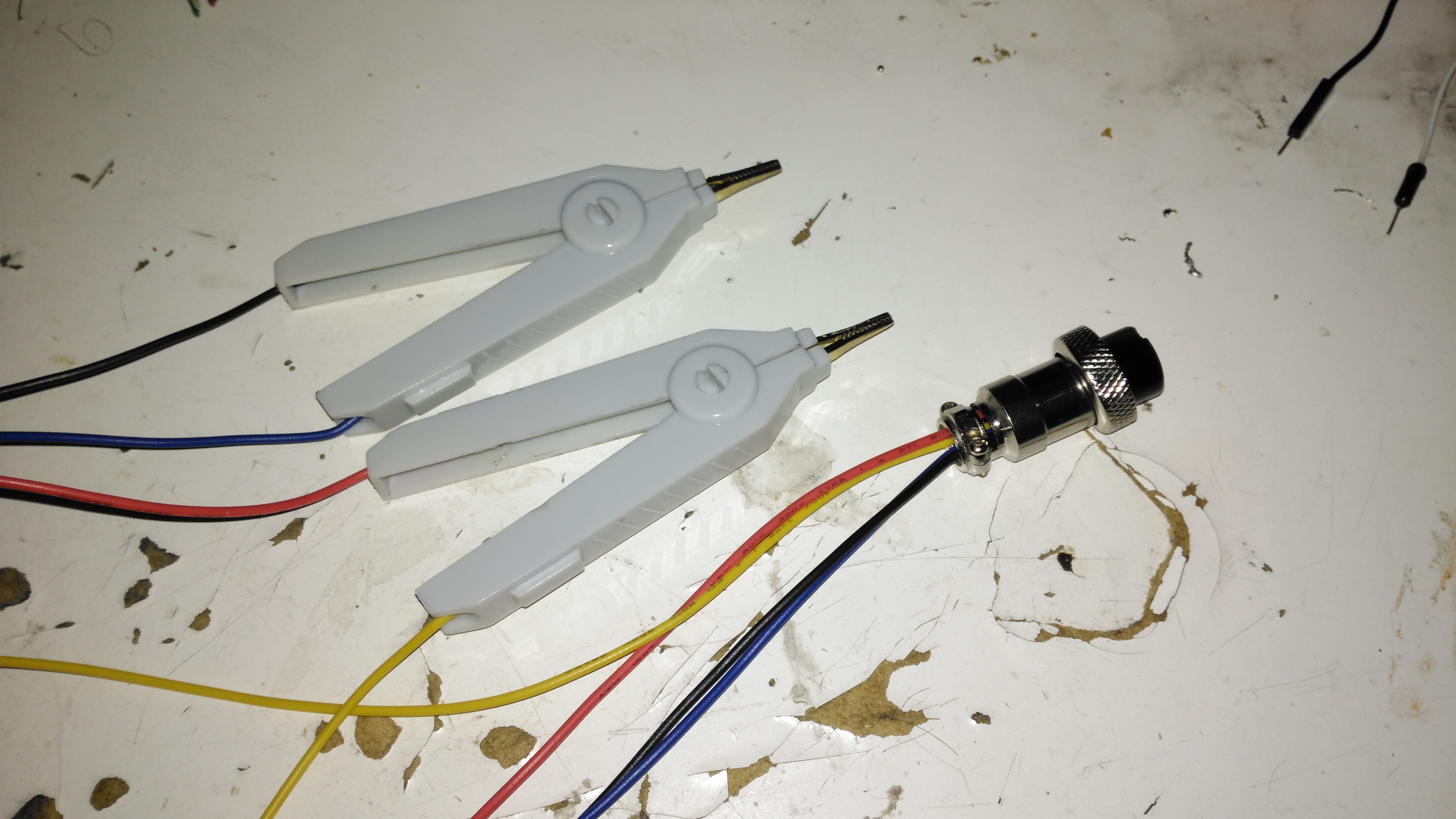
The inputs on the side of the enclosure. I’ve used the same 6-pin round connector for the probes, power is applied to the Arduino when the probes are plugged in.
Module Installed
Everything installed in the enclosure – it’s a pretty tight fit especially with the lithium cell in place.
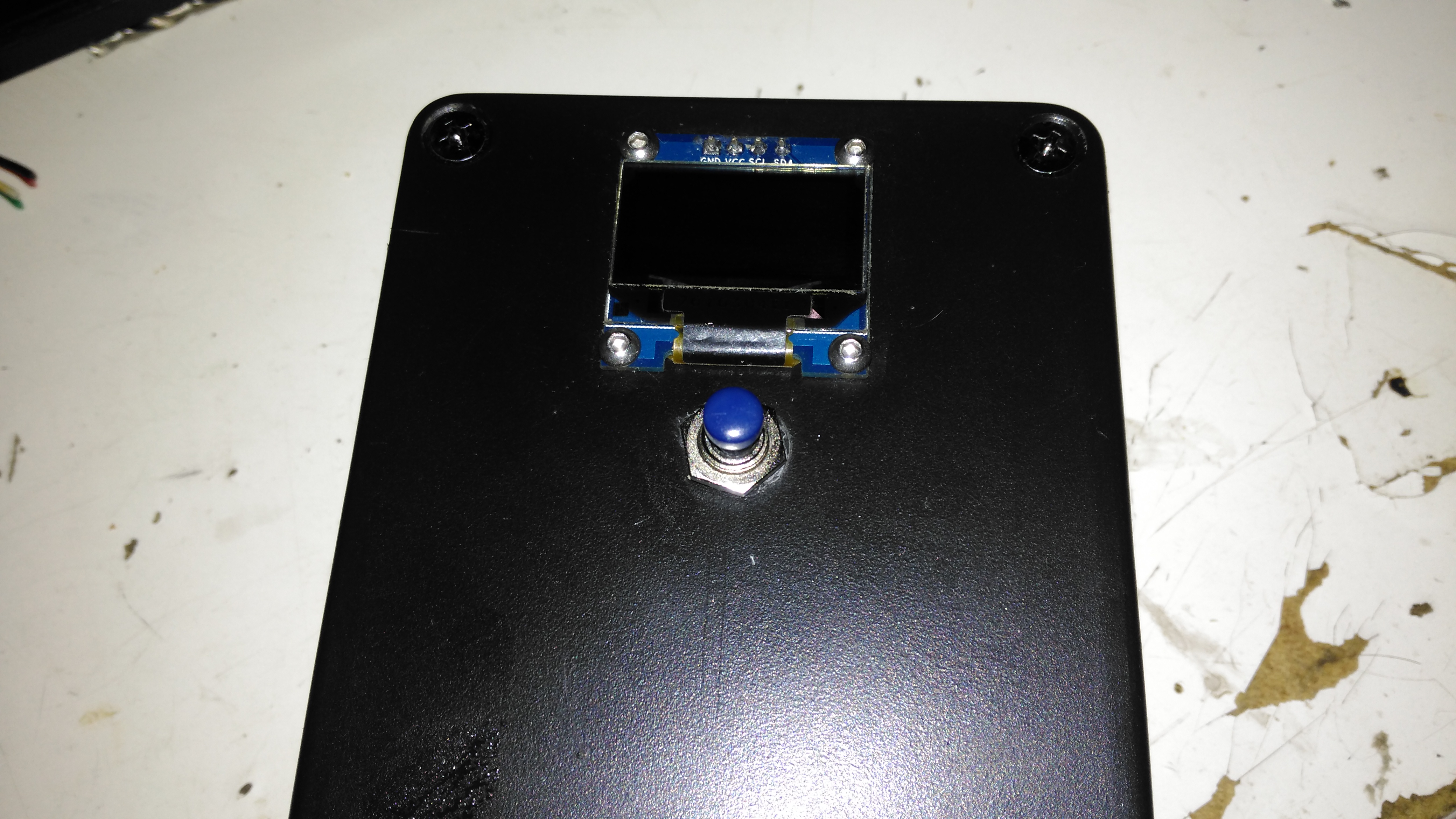
Meter Top Cover
The top cover has the Measure button, and the OLED display panel, the latter secured to the case with M2.5 cap head screws.
Kelvin Clips
Finally, the measurement loom, with Kelvin clips. These were an eBay buy, keeping things cheap. These clips seem to be fairly well built, even if the hinges are plastic. I doubt they’re actually gold-plated, more likely to be brass. I haven’t noticed any error introduced by these cheap clips so far.
The modified sketch is below:
// ---------------------------------------------------------------------------------------------
//  Simple, accurate milliohmeter
//
//  (c) Mark Driedger 2015
//
//  - Determines resistance using 4 wire measurement of voltage across a series connected
//  reference resistor (Rr, 10 ohm, 0.1%) and test resistor (Rx)
//  - range of accurate measurement is roughly 50 mohm to 10Kohm
//  - Uses Arduino digital I/O ports to deliver the test current, alternating polarity to cancel
//  offset errors (synchronous detector)
//  - 4 I/O pins are used for each leg of the test current to increase test current
//  - Averages 2 cycles and 100 samples/cycle
//  - Uses a 16 bit ADC ADS1115 with 16x PGA to improve accuracy
//
//  Version History
//    May 24/15    v1.0-v4.0
//      - initial development versions
//    May 27/15    v5.0
//      - changed display to I2C
//      - backed out low power module since it seemed to cause serial port upload problems
// ---------------------------------------------------------------------------------------------

#include <Wire.h>
#include <SPI.h>
#include <Adafruit_GFX.h>
#include <Adafruit_SSD1306.h>
//#include <LowPower.h>

#if (SSD1306_LCDHEIGHT != 64)
#error("Height incorrect, please fix Adafruit_SSD1306.h!");
#endif

// ---------------------------------------------------------------------------------------------
//  I/O port usage
// ---------------------------------------------------------------------------------------------
//    serial port (debug and s/w download)    0, 1
//    I²C interface to ADC & display          A4, A5
//    positive drive                          2, 3, 4, 5
//    push to test input                      8
//    unused                                  9, 10, 11, A0, A1, A2, A6, A7
//    negative drive                          6, 7, 8, 9
//    battery voltage monitor                 A3
//    debug output                            13

#define  P_PushToTest  10       // push button (measure), active low
#define  P_Debug       13
#define  CHG           12

//  ADS1115 mux and gain settings
#define  ADS1115_CH01  0x00    // p = AIN0, n = AIN1
#define  ADS1115_CH03  0x01    // ... etc
#define  ADS1115_CH13  0x02
#define  ADS1115_CH23  0x03
#define  ADS1115_CH0G  0x04    // p = AIN0, n = GND
#define  ADS1115_CH1G  0x05    // ... etc
#define  ADS1115_CH2G  0x06
#define  ADS1115_CH3G  0x07

#define  ADS1115_6p144  0x00   // +/- 6.144 V full scale
#define  ADS1115_4p096  0x01   // +/- 4.096 V full scale
#define  ADS1115_2p048  0x02   // +/- 2.048 V full scale
#define  ADS1115_1p024  0x03   // +/- 1.024 V full scale
#define  ADS1115_0p512  0x04   // +/- 0.512 V full scale
#define  ADS1115_0p256  0x05   // +/- 0.256 V full scale
#define  ADS1115_0p256B 0x06   // same as ADS1115_0p256
#define  ADS1115_0p256C 0x07   // same as ADS1115_0p256

Adafruit_SSD1306   display(0);               // using I2C interface, no reset pin
static int         debug_mode = 0;           // true in debug mode

float ADS1115read(byte channel, byte gain)
//--------------------------------------------------------------------------------------
//  reads a single sample from the ADS1115 ADC at a given mux (channel) and gain setting
//  - channel is 3 bit channel number/mux setting (one of ADS1115_CHxx)
//  - gain is 3 bit PGA gain setting (one of ADS1115_xpxxx)
//  - returns voltage in volts
//  - uses single shot mode, polling for conversion complete, default I2C address
//  - conversion takes approximatly 9.25 msec
//--------------------------------------------------------------------------------------
  {
  const int    address = 0x48;      // ADS1115 I2C address, A0=0, A1=0
  byte         hiByte, loByte;
  int          r;
  float        x;

  channel &= 0x07;                  // constrain to 3 bits
  gain    &= 0x07;

  hiByte = B10000001 | (channel<<4) | (gain<<1);    // conversion start command
  loByte = B10000011;

  Wire.beginTransmission(address);  // send conversion start command
  Wire.write(0x01);                 // address the config register
  Wire.write(hiByte);               // ...and send config register value
  Wire.write(loByte);
  Wire.endTransmission();

   do                               // loop until conversion complete
    {
    Wire.requestFrom(address, 2);   // config register is still addressed
    while(Wire.available())
      {
      hiByte = Wire.read();         // ... and read config register
      loByte = Wire.read();
      }
    }
  while ((hiByte & 0x80)==0);       // upper bit (OS) is conversion complete

  Wire.beginTransmission(address);
  Wire.write(0x00);                 // address the conversion register
  Wire.endTransmission();

  Wire.requestFrom(address, 2);     // ... and get 2 byte result
  while(Wire.available())
    {
    hiByte = Wire.read();
    loByte = Wire.read();
    }

  r = loByte | hiByte<<8;           // convert to 16 bit int
  switch(gain)                      // ... and now convert to volts
    {
      case ADS1115_6p144:  x = r * 6.144 / 32768.0; break;
      case ADS1115_4p096:  x = r * 4.096 / 32768.0; break;
      case ADS1115_2p048:  x = r * 2.048 / 32768.0; break;
      case ADS1115_1p024:  x = r * 1.024 / 32768.0; break;
      case ADS1115_0p512:  x = r * 0.512 / 32768.0; break;
      case ADS1115_0p256:
      case ADS1115_0p256B:
      case ADS1115_0p256C: x = r * 0.256 / 32768.0; break;
    }
  return x;
  }

// ---------------------------------------------------------------------------------------------
//  Drive functions
//   - ports 4-7 and A0-A3 are used to differentially drive resistor under test
//   - the ports are resistively summed to increase current capability
//   - DriveOff() disables the drive, setting the bits to input
//   - DriveOn()  enables the drive,  setting the bits to output
//   - DriveP()   enables drive with positive current flow (from ports 4-7 to ports A0-A3)
//   - DriveN()   enables drive with negative current flow
// ---------------------------------------------------------------------------------------------
void DriveP()
  {
    DriveOff();
    digitalWrite( 2, HIGH);
    digitalWrite( 3, HIGH);
    digitalWrite( 4, HIGH);
    digitalWrite( 5, HIGH);
    digitalWrite( 6, LOW);
    digitalWrite( 7, LOW);
    digitalWrite( 8, LOW);
    digitalWrite( 9, LOW);
    DriveOn();
  }

void DriveN()
  {
    DriveOff();
    digitalWrite( 2, LOW);
    digitalWrite( 3, LOW);
    digitalWrite( 4, LOW);
    digitalWrite( 5, LOW);
    digitalWrite( 6, HIGH);
    digitalWrite( 7, HIGH);
    digitalWrite( 8, HIGH);
    digitalWrite( 9, HIGH);
    DriveOn();
  }

void DriveOn()
  {
    pinMode( 2, OUTPUT);      // enable source/sink in pairs
    pinMode( 6, OUTPUT);
    pinMode( 3, OUTPUT);
    pinMode( 7, OUTPUT);
    pinMode( 4, OUTPUT);
    pinMode( 8, OUTPUT);
    pinMode( 5, OUTPUT);
    pinMode( 9, OUTPUT);
    delayMicroseconds(5000);  // 5ms delay
  }

void DriveOff()
  {
    pinMode( 2, INPUT);       // disable source/sink in pairs
    pinMode( 6, INPUT);
    pinMode( 3, INPUT);
    pinMode( 7, INPUT);
    pinMode( 4, INPUT);
    pinMode( 8, INPUT);
    pinMode( 5, INPUT);
    pinMode( 9, INPUT);
  }

int CalcPGA(float x)
// ---------------------------------------------------------------------------------------------
//   Calculate optimum PGA setting based on a sample voltage, x, read at lowest PGA gain
//     - returns the highest PGA gain that allows x to be read with 10% headroom
// ---------------------------------------------------------------------------------------------
  {
    x = abs(x);
    if (x>3.680) return ADS1115_6p144;
    if (x>1.840) return ADS1115_4p096;
    if (x>0.920) return ADS1115_2p048;
    if (x>0.460) return ADS1115_1p024;
    if (x>0.230) return ADS1115_0p512;
    else         return ADS1115_0p256;
  }

void BatteryIcon(float charge)
// ---------------------------------------------------------------------------------------------
//   Draw a battery charge icon into the display buffer without refreshing the display
//     - charge ranges from 0.0 (empty) to 1.0 (full)
// ---------------------------------------------------------------------------------------------
  {
    static const unsigned char PROGMEM chg[] =     // Battery Charge Icon
    { 0x1c, 0x18, 0x38, 0x3c, 0x18, 0x10, 0x20, 0x00 };

    int w = constrain(charge, 0.0, 1.0)*16;  // 0 to 16 pixels wide depending on charge
    display.drawRect(100, 0, 16, 7, WHITE);  // outline
    display.drawRect(116, 2,  3, 3, WHITE);  // nib
    display.fillRect(100, 0,  w, 7, WHITE);  // charge indication

    //battery charging indication
    pinMode(CHG, INPUT);
    if (digitalRead(CHG) == HIGH)
      display.drawBitmap(91, 0, chg, 8, 8, WHITE);
  }

void f2str(float x, int N, char *c)
// ---------------------------------------------------------------------------------------------
//    Converts a floating point number x to a string c with N digits of precision
//     - *c must be a string array of length at least N+3 (N + '-', '.', '\0')
//     - x must be have than N leading digits (before decimal) or "#\0" is returned
// ---------------------------------------------------------------------------------------------
  {
  int     j, k, r;
  float   y;

  if (x<0.0)                    // handle negative numbers
    {
      *c++ = '-';
      x = -x;
    }
  for (j=0; x>=1.0; j++)        // j digits before decimal point
    x /= 10.0;                  // .. and scale x to be < 1.0

  if (j>N)                      // return error string if too many digits
    {
      *c++ = '#';
      *c++ = '\0';
      return;
    }

  y = pow(10, (float) N);       // round to N digits
  x = round(x * y) / y;
  if (x>1.0)                    // if 1st digit rounded up ...
    {
      x /= 10.0;                // then normalize back down 1 digit
      j++;
    }

  for (k=0; k<N; k++)
    {
      r = (int) (x*10.0);        // leading digit as int
      x = x*10-r;                // remove leading digit and shift 1 digit

      *c++ = r + '0';            // add leading digit to string
      if (k==j-1 && k!=N-1)      // add decimal point after j digits
        *c++ = '.';              // ... unless there are N digits before decimal
    }
  *c++ = '\0';
  }

void DisplayResistance(float x)
// ---------------------------------------------------------------------------------------------
//    Adds the resistance value, x, to the display buffer without refreshing the display
//      - converts to kohm, milliohm or microohm if necessary
// ---------------------------------------------------------------------------------------------
  {
    static const unsigned char PROGMEM omega_bmp[] =     // omega (ohm) symbol
    { B00000011, B11000000,
      B00001100, B00110000,
      B00110000, B00001100,
      B01000000, B00000010,
      B01000000, B00000010,
      B10000000, B00000001,
      B10000000, B00000001,
      B10000000, B00000001,
      B10000000, B00000001,
      B10000000, B00000001,
      B01000000, B00000010,
      B01000000, B00000010,
      B01000000, B00000010,
      B00100000, B00000100,
      B00010000, B00001000,
      B11111000, B00011111 };

    char  s[8];
    char  prefix;

    if (x>=1000.0)          // display in killo ohms
      {
        x /= 1000.0;
        prefix = 'k';
      }
    else if (x<0.001)       // display in micro ohms
      {
        x *= 1000000.0;
        prefix = 0xe5;    // mu
      }
    else if (x<1.0)         // display in milli ohms
      {
        x *= 1000.0;
        prefix = 'm';
      }
    else
      prefix = ' ';         // display in ohms

    f2str(x, 5, s);

    // display computed resistance
    display.setTextSize(2);
    display.setTextColor(WHITE);
    display.setCursor(0,20);
    display.print(s);

    // display prefix
    display.setCursor(85,20);
    display.print(prefix);

    // display omega (ohms) symbol
    display.drawBitmap(103, 18, omega_bmp, 16, 16, WHITE);
  }

void DisplayDebug(int a, int b, float x, float y, float Vbat)
// ---------------------------------------------------------------------------------------------
//    Adds debug info to the display buffer without showing the updated display
//      - Adds 2 ints (a, b) and a float(Vbat) to the top line and 2 floats (x, y)
//      to the bottom line+, all in small (size 1) text
// ---------------------------------------------------------------------------------------------
  {
    // display x, y in lower left, small font
    display.setTextSize(1);
    display.setCursor(0,45);
    display.print(x,3);
    display.print("  ");
    display.print(y,3);

    // display a, b in upper left, small font
    display.setTextSize(1);
    display.setCursor(0,0);
    display.print(a);
    display.print("  ");
    display.print(b);

    // display Vbat in upper middle, small font
    display.setTextSize(1);
    display.setCursor(60,0);
    display.print(Vbat,1);
  }

void DisplayStr(char *s)
// ---------------------------------------------------------------------------------------------
//    Adds a string, s, to the display buffer without refreshing the display @ (0,20)
// ---------------------------------------------------------------------------------------------
  {
    display.setTextSize(2);
    display.setTextColor(WHITE);
    display.setCursor(8,20);
    display.print(s);
  }

#ifdef TESTMODE
void loop()
  {
    while (digitalRead(P_PushToTest))
      ;
    DriveP();
    display.clearDisplay();
    DisplayStr("Drive: +");
    display.display();
    delay(250);

    while (digitalRead(P_PushToTest))
      ;
    DriveN();
    display.clearDisplay();
    DisplayStr("Drive: -");
    display.display();
    delay(250);

    while (digitalRead(P_PushToTest))
      ;
    DriveOff();
    display.clearDisplay();
    DisplayStr("Drive: Off");
    display.display();
    delay(250);
  }
#endif

void setup()
// ---------------------------------------------------------------------------------------------
//    - initializae display and I/O ports
// ---------------------------------------------------------------------------------------------
  {
    DriveOff();                                    // disable current drive
    Wire.begin();                                  // join I2C bus
    display.begin(SSD1306_SWITCHCAPVCC, 0x3c, 0);  // initialize display @ address 0x3c, no reset
    pinMode(P_PushToTest, INPUT_PULLUP);           // measure push button switch, active low
    debug_mode = !digitalRead(P_PushToTest);       // if pushed during power on, then debug mode
    pinMode(P_Debug, OUTPUT);                      // debug port
  }

void loop()
// ---------------------------------------------------------------------------------------------
//    main measurement loop
// ---------------------------------------------------------------------------------------------
  {
    const float      Rr = 10.0;             // reference resistor value, ohms
    const float      Rcal = 1.002419;       // calibration factor
    const int        N = 2;                 // number of cycles to average
    const int        M = 50;                // samples per half cycle
    static long      Toff;
    double           Rx;                    // calculated resistor under test, ohms
    byte             PGAr, PGAx;            // PGA gains (r = reference, x = test resistors)
    float            Vr, Vx, Wx, Wr;        // voltages in V
    float            Rn;                    // calculated resistor under test, ohms, single sample
    double           Avgr, Avgx;            // average ADC readings in mV
    int              j, k, n;
    float            Vbat;                  // battery voltage in V (from 2:1 divider)
    char             serialbuff[10];        // Buffer for sending the reading over I²C

    display.clearDisplay();
    DisplayStr("measuring");
    display.display();

    // determine PGA gains
    DriveP();
    Wr =  ADS1115read(ADS1115_CH01, ADS1115_6p144);
    Wx =  ADS1115read(ADS1115_CH23, ADS1115_6p144);
    DriveN();
    Vr = -ADS1115read(ADS1115_CH01, ADS1115_6p144);
    Vx = -ADS1115read(ADS1115_CH23, ADS1115_6p144);

    //  measure battery voltage ... while drive is on so there is a load
    Vbat = analogRead(A3)*5.0/1024.0;    // 2:1 divider (5V FS) on 4.2v lithium battery

    DriveOff();

    PGAr = CalcPGA(max(Vr, Wr));           // determine optimum PGA gains
    PGAx = CalcPGA(max(Vx, Wx));

    // measure resistance using synchronous detection
    Avgr = Avgx = 0.0;                     // clear averages
    Rx = 0.0;
    n = 0;
    for (j=0; j<N; j++)                    // for each cycle
      {
        DriveP();                          // turn on drive, positive
        for (k=0; k<M; k++)
          {
            digitalWrite(P_Debug, 1);
            Vx = ADS1115read(ADS1115_CH23, PGAx);
            digitalWrite(P_Debug, 0);
            Vr = ADS1115read(ADS1115_CH01, PGAr);
            Avgx += Vx;
            Avgr += Vr;
            Rn = Vx/Vr;
            if (Rn>0.0 && Rn<10000.0)
              {
              Rx += Rn;
              n++;
              }
          }

        DriveN();                          // turn on drive, negative
        for (k=0; k<M; k++)
          {
            digitalWrite(P_Debug, 1);
            Vx = ADS1115read(ADS1115_CH23, PGAx);
            digitalWrite(P_Debug, 0);
            Vr = ADS1115read(ADS1115_CH01, PGAr);
            Avgx -= Vx;
            Avgr -= Vr;
            Rn = Vx/Vr;
            if (Rn>0.0 && Rn<10000.0)
              {
              Rx += Rn;
              n++;
              }
          }
      }

    DriveOff();
    Rx   *= Rr * Rcal / n;                 // apply calibration factor and compute average
    Avgr *= 1000.0 / (2.0*N*M);            // average in mV
    Avgx *= 1000.0 / (2.0*N*M);

    // display the results ... battery icon, Rx measurement, debug info if requested
    display.clearDisplay();                // ... and display result
    BatteryIcon((Vbat-3.0)/(4.2-3.0));     // 7.5V = 0%, 9V = 100%
    //display.drawLine(0, 8, 127, 8, WHITE); //Draw separator line under icons
    if (n==0){                              // no measurement taken ...
      display.setTextSize(2);
      display.setCursor(51,20);
      display.print(F("OL"));
    }
      //DisplayStr("-----");
    else
      DisplayResistance(Rx);
    //Send Reading via I²C
      Wire.beginTransmission(0x50);
      Wire.write(dtostrf(Rx, 5, 5, serialbuff));
      Wire.endTransmission();
    if (debug_mode)
      DisplayDebug(PGAr, PGAx, Avgr, Avgx, Vbat);
    display.display();                     // show the display

    // and then wait for next measurement request
    Toff = millis()+60000L;
    while(digitalRead(P_PushToTest))       // loop until measure button pressed
      {
        // Enter power down state for 120ms with ADC and BOD module disabled
        //LowPower.powerDown(SLEEP_120MS, ADC_OFF, BOD_OFF);
        if (millis()>Toff)                 // after 7 seconds ...
          {
            display.clearDisplay();        // clear display
            display.display();
          }
      }
  }
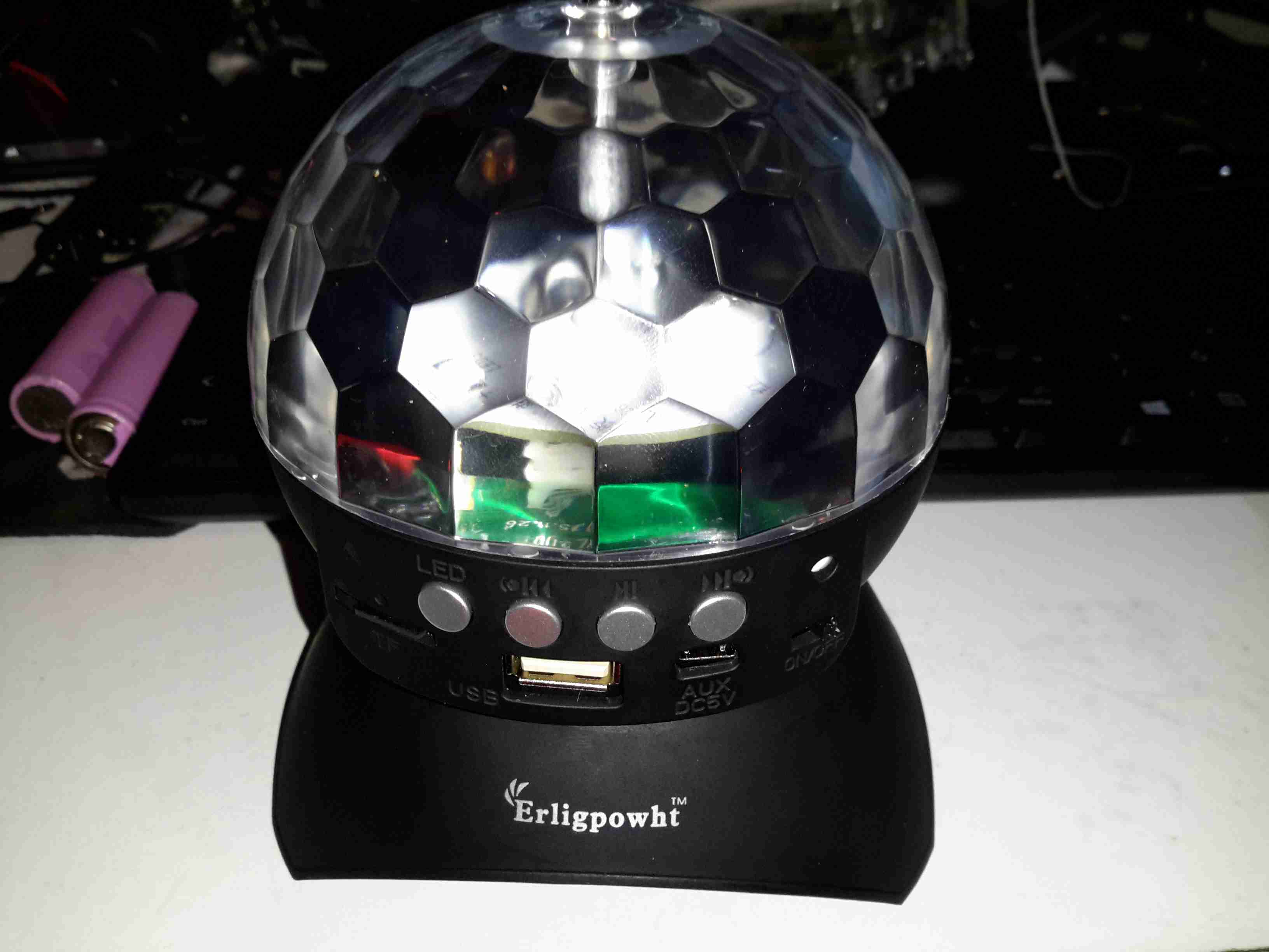
Here’s an eBay oddity – it’s got the same light & lens mechanism as the cheap “disco light” style bulbs on eBay, but this one is battery powered & has a built in MP3 player.
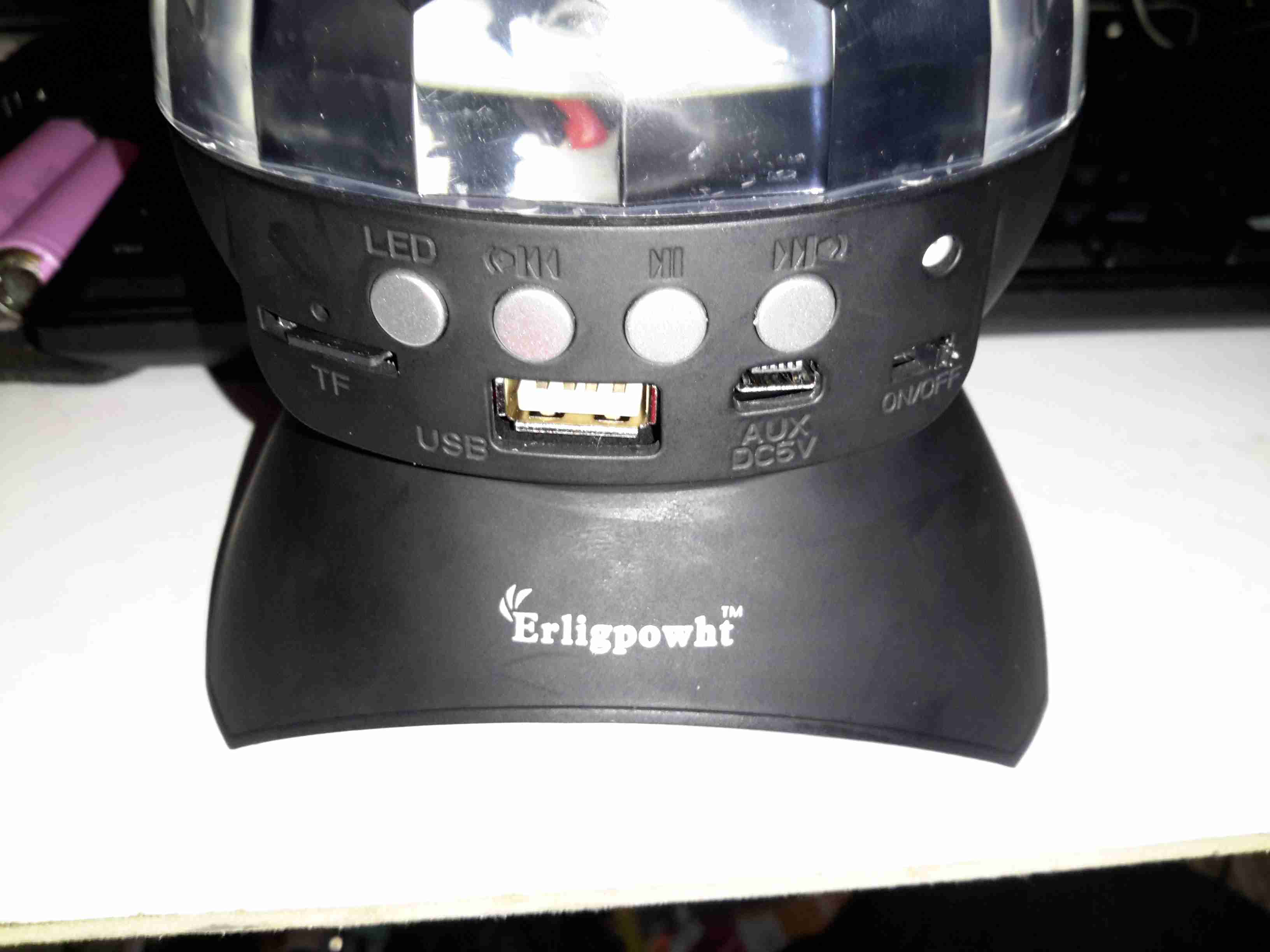
MP3 Disco Light
This device simply oozes cheapness. The large 4″ plastic dome lens sits on the top above the cheap plastic moulding as a base, which also contains the MP3 player speaker.
Controls
There are few controls on this player, the volume buttons are combined with the skip track buttons, a long press operates the volume control, while a short press skips the tracks. Several options for getting this thing to play music are provided:
Bluetooth – Allows connection from any device for bluetooth audio
USB – Plugging in a USB flash drive with MP3 files
SD Card – Very similar to the USB flash drive option, just a FAT32 formatted card with MP3 files
Aux – There’s no 3.5mm jack on this unit for an audio input, instead a “special” USB cable is supplied that is both used to charge the built in battery & feed an audio signal. This is possible since the data lines on the port aren’t used. But it’s certainly out of the ordinary.
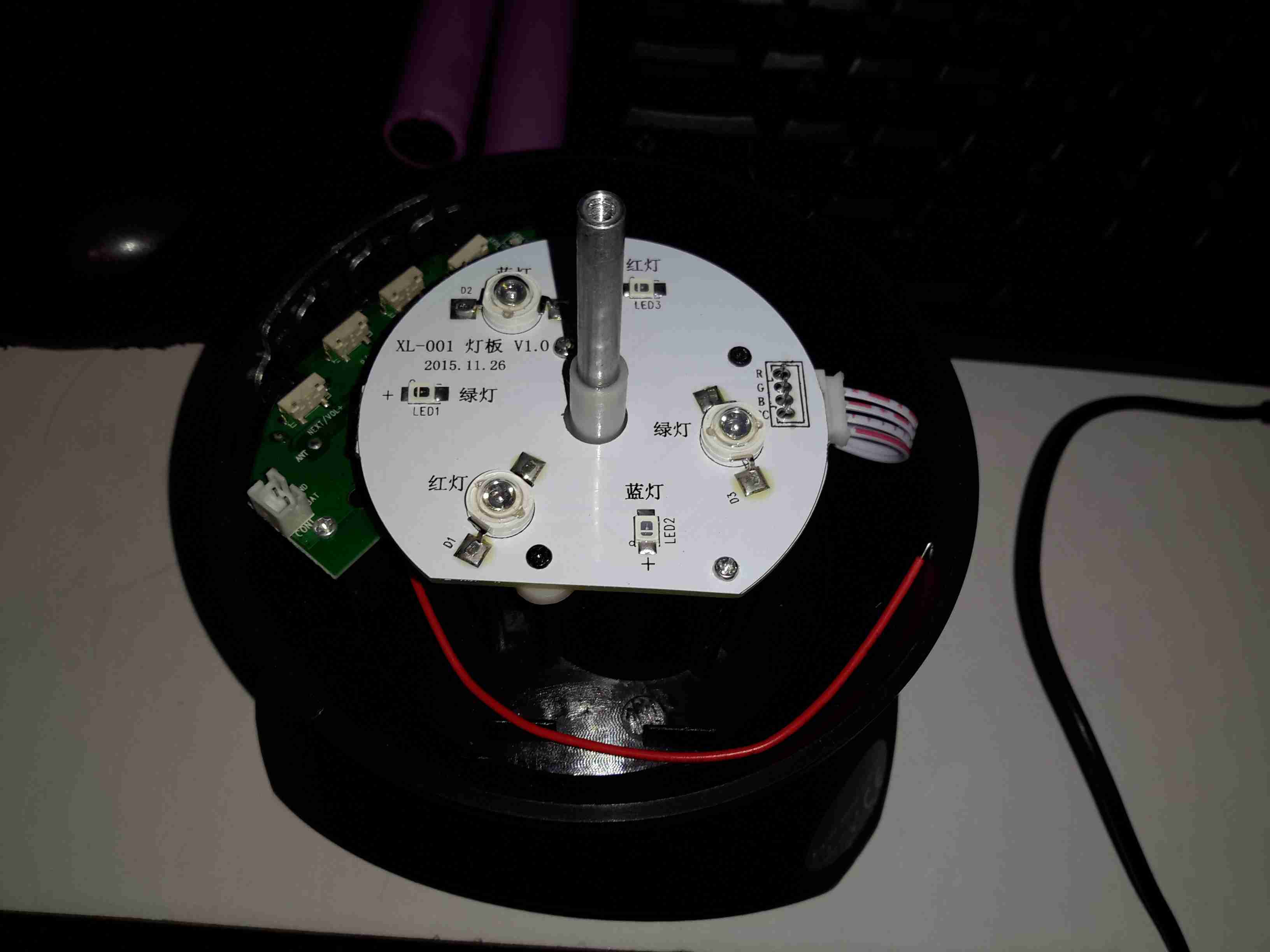
Top Removed
The top comes off with the removal of a single screw in the centre of the lens. The shaft in the centre that holds the lens is attached to a small gear motor under the LED PCB. There’s 6 LEDs on the board, to form an RGB array. Surprisingly for a very small battery powered unit these are bright to the point of being utterly offensive.
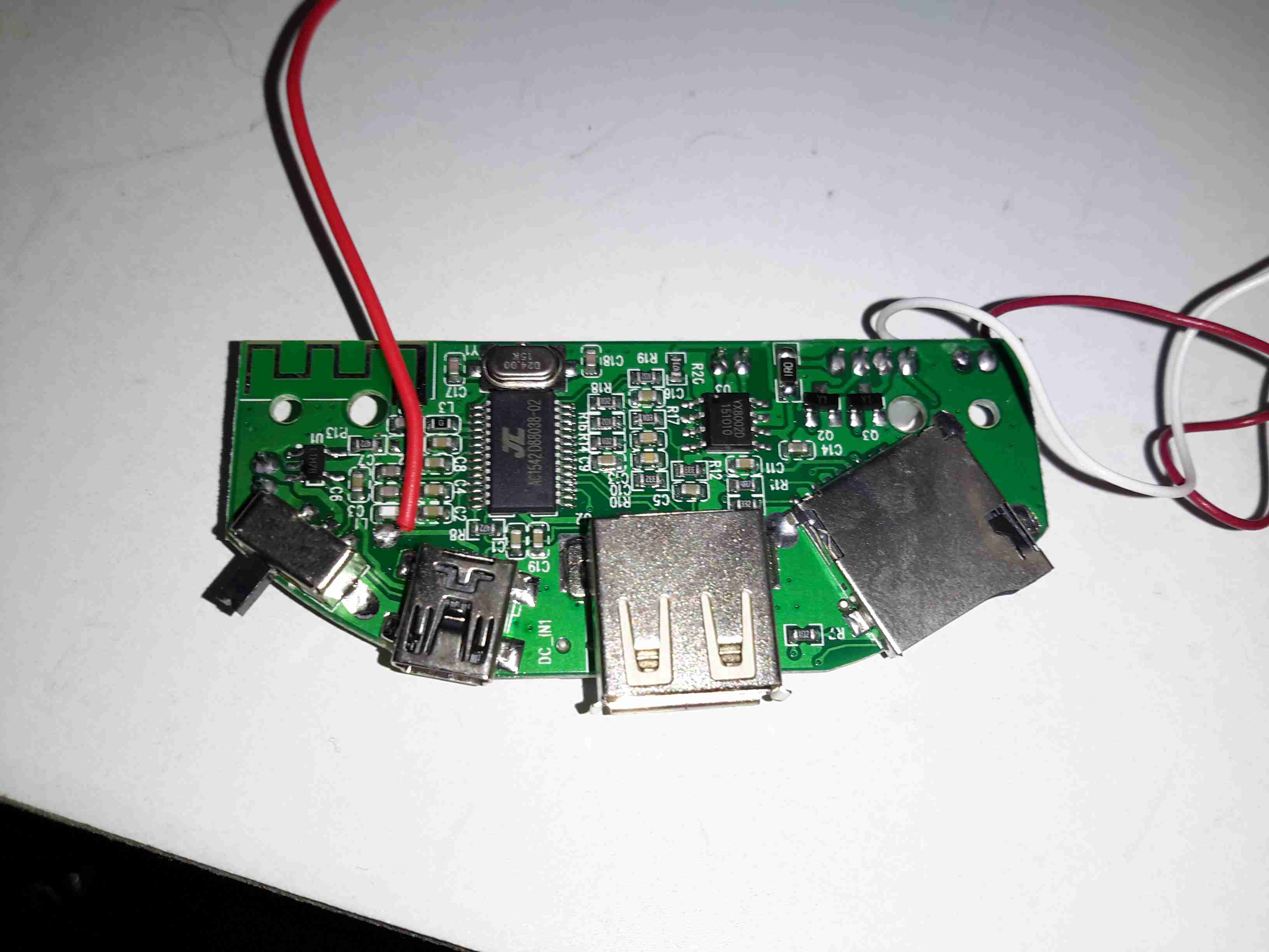
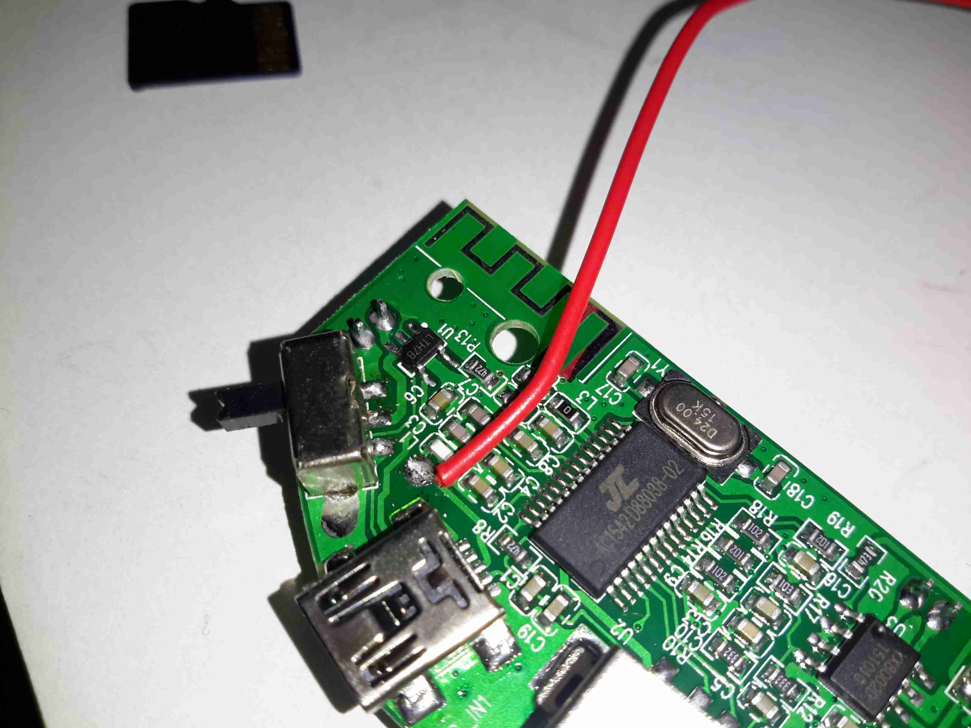
Mainboard
Here’s the mainboard removed from the plastic base. There’s not much to this device, even with all the options it has. The power switch is on the left, followed by the Mini-B USB charging port & aux audio input. The USB A port for a flash drive is next, finishing with the µSD slot. I’m not sure what the red wire is for on the left, it connects to one of the pins on the USB port & then goes nowhere.
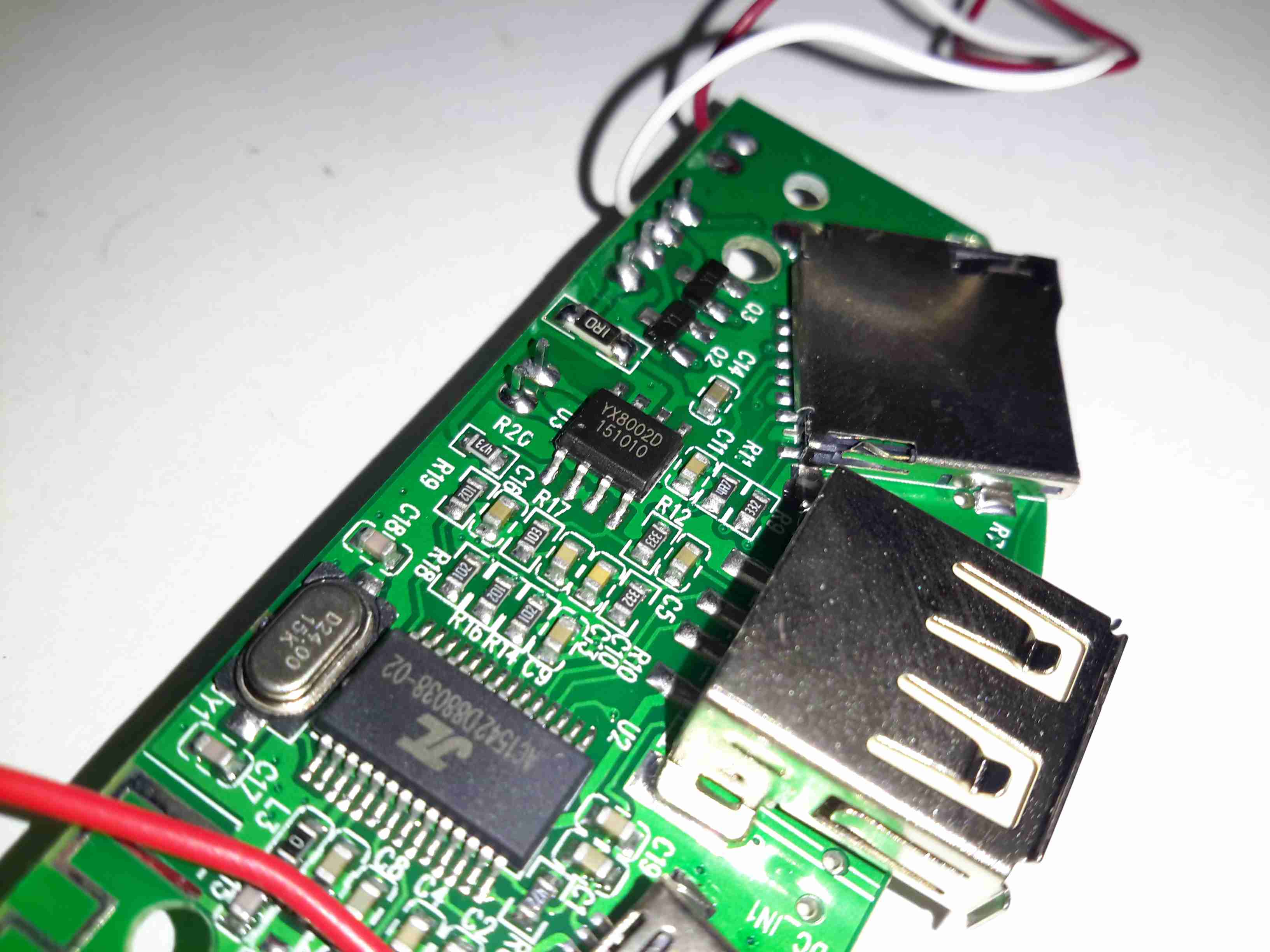
Audio Amplifier
The audio amplifier is a YX8002D, I couldn’t find a datasheet for this, but it’s probably Class D.
Main Chipset
Finally there’s the main IC, which is an AC1542D88038. I’ve not been able to find any data on this part either, it’s either a dedicated MP3 player with Bluetooth radio built in, or an MCU of some kind.The RF antenna for the Bluetooth mode is at the top of the board.
Just behind the power switch is a SOT23-6 component, which should be the charger for the built in Lithium Ion cell.
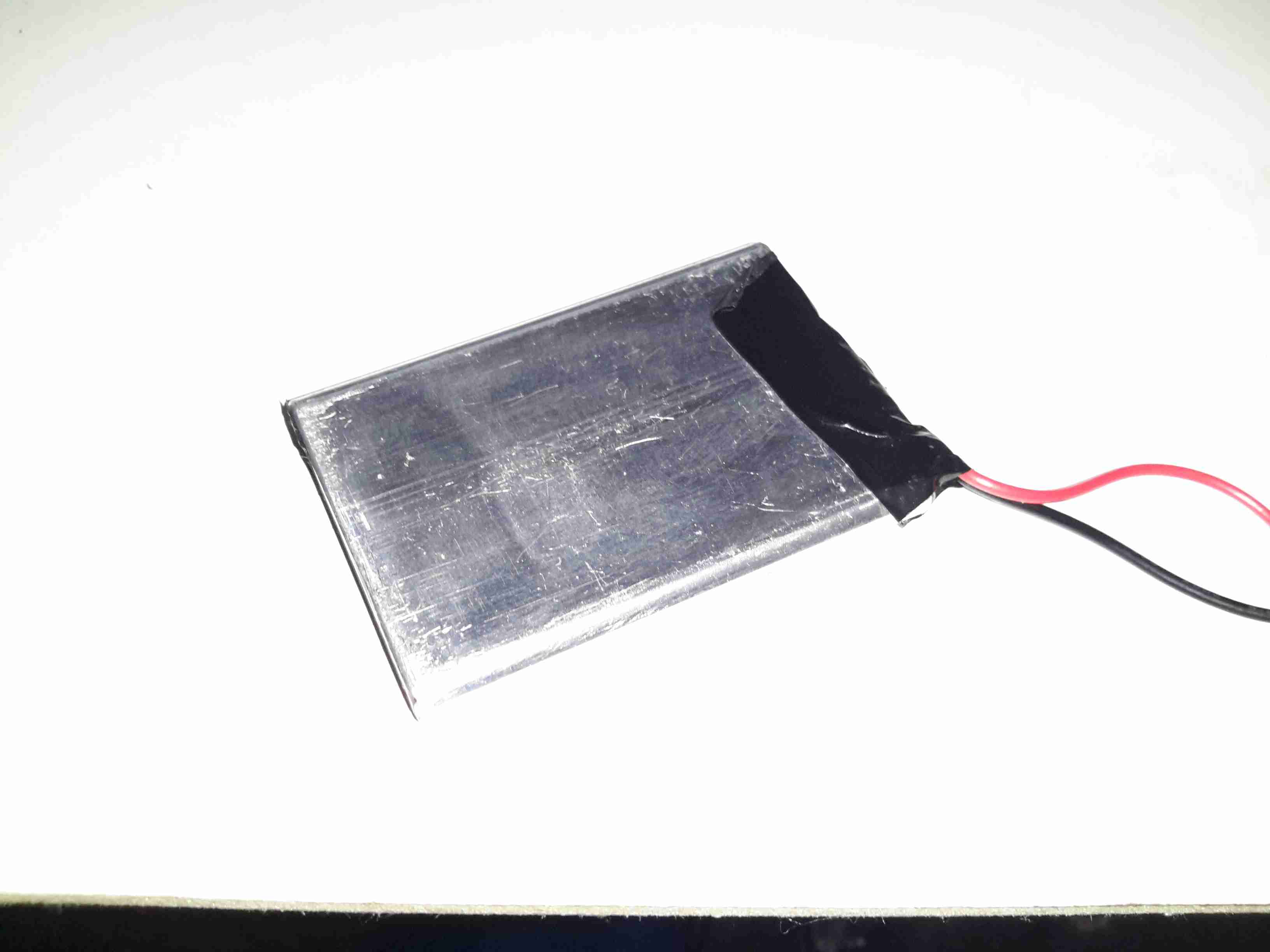
Lithium Ion Cell
The cell itself is a prismatic type rated in the instructions at 600mAh, however my 1C discharge test gave a reading of 820mAh, which is unusual for anything Li-Ion based that comes from eBay 😉
There is cell protection provided, it’s under the black tape on the end, nothing special here.
The main issue so far with this little player is the utterly abysmal battery life – at full volume playing MP3s from a SD card, the unit’s current draw is 600mA, with the seizure & blindness-inducing LEDs added on top, the draw goes up to about 1200mA. The built in charger is also not able to keep up with running the player while charging. This in all only gives a battery life of about 20 minutes, which really limits the usability of the player.
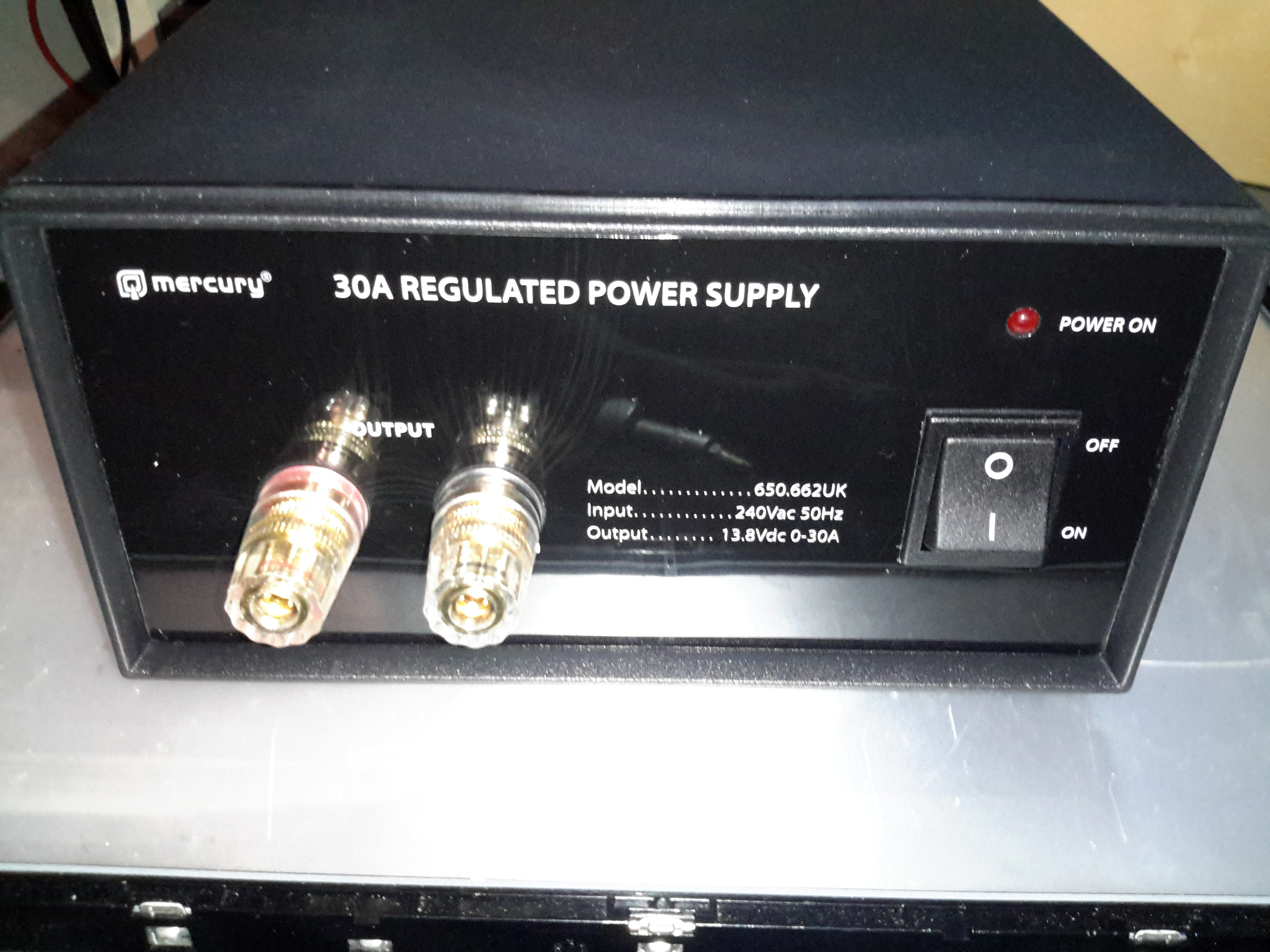
After having a couple of the cheap Chinese PSUs fail on me in a rather spectacular fashion, I decided to splash on a more expensive name-brand PSU, since constantly replacing PSUs at £15 a piece is going to get old pretty fast. This is the 30A model from Mercury, which seems to be pretty well built. It’s also significantly more expensive at £80. Power output is via the beefy binding posts on the front panel. There isn’t any metering on board, this is something I’ll probably change once I’ve ascertained it’s reliability. This is also a fixed voltage supply, at 13.8v.
Rear Panel
Not much on the rear panel, just the fuse & cooling fan. This isn’t temperature controlled, but it’s not loud. No IEC power socket here, the mains cable is hard wired.
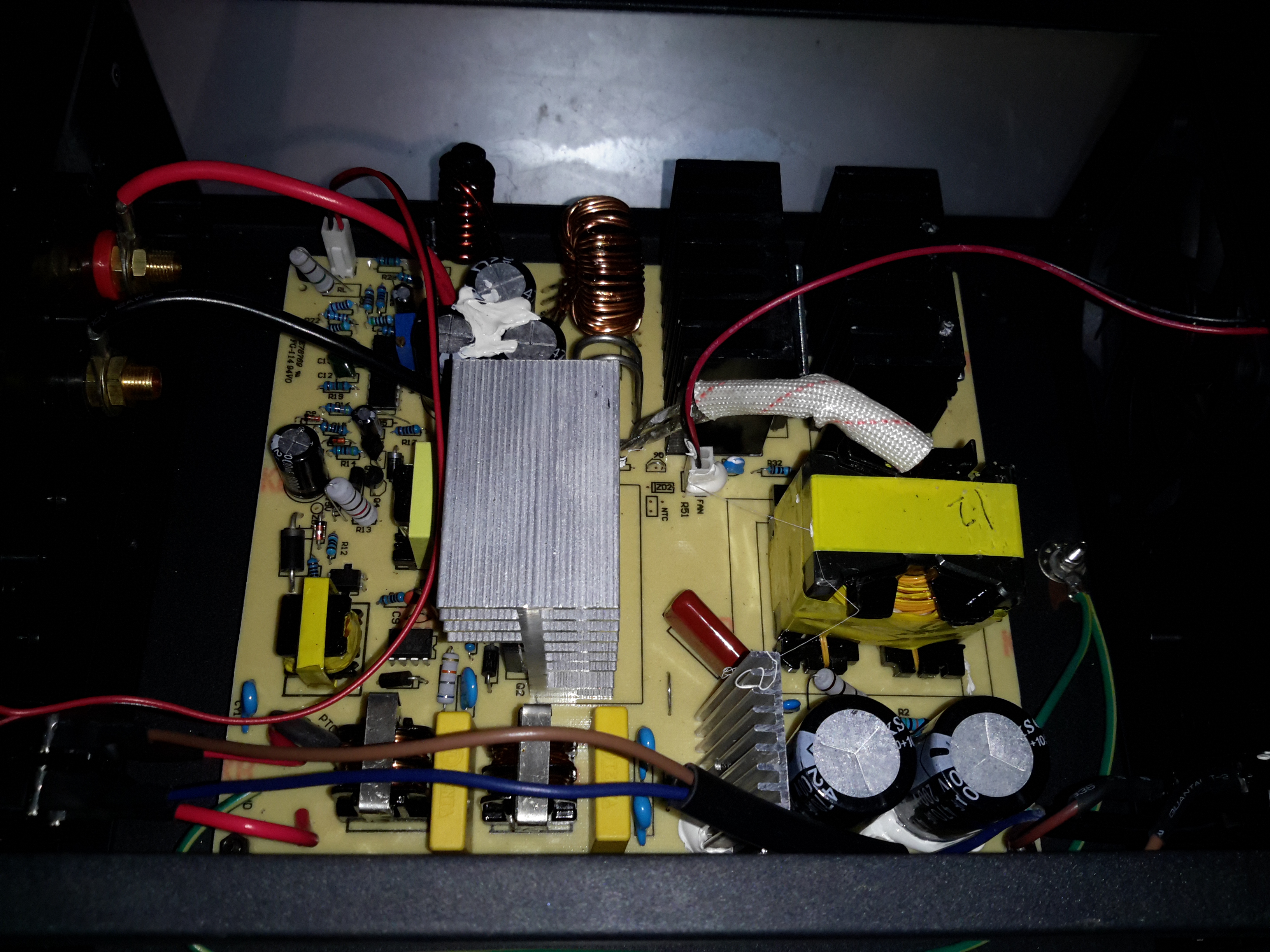
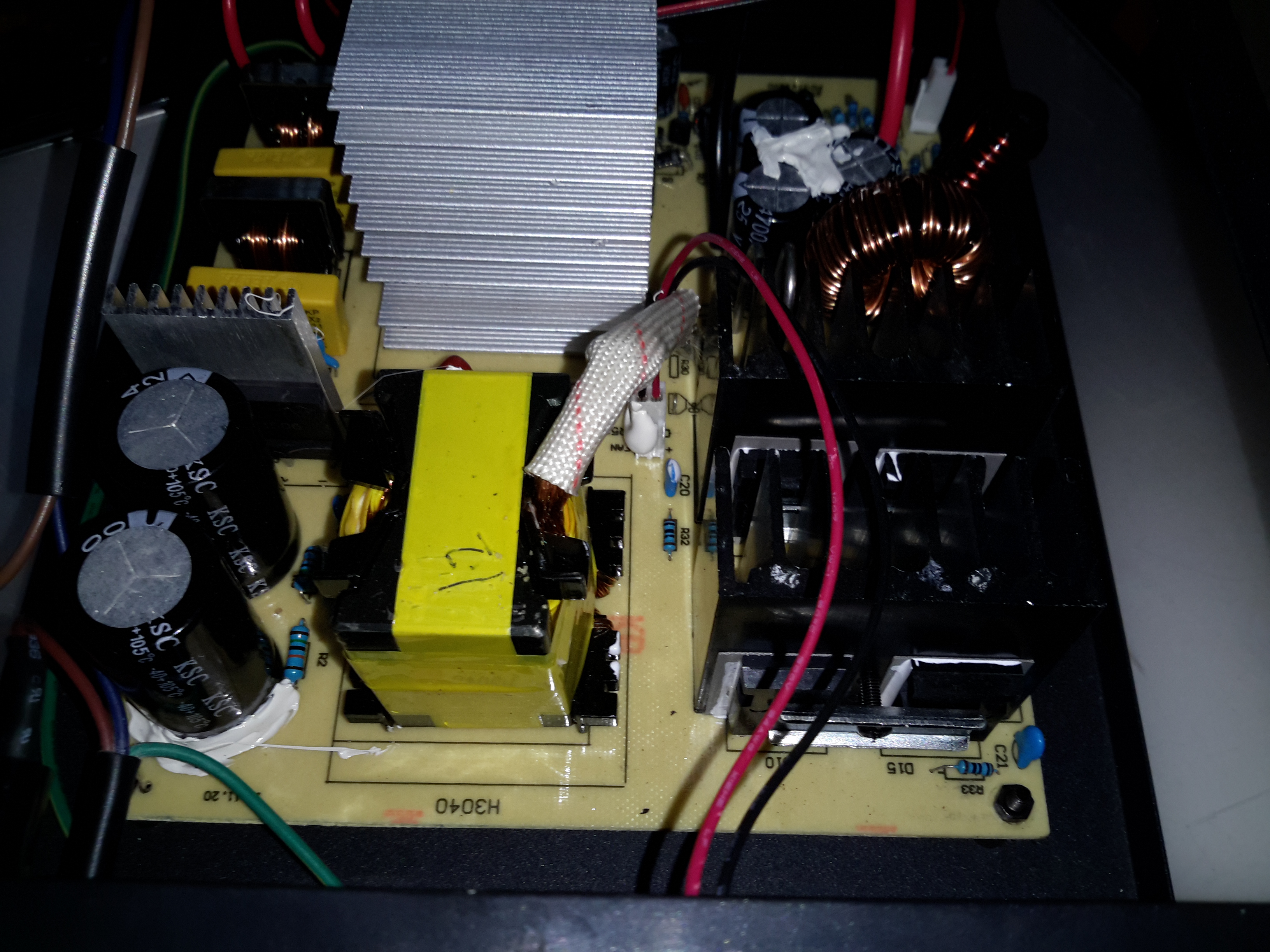
Main Board
Removing some spanner-type security screws reveals the power supply board itself. Everything on here is enormous to handle the 30A output current at 13.8v. The main primary side switching transistors are on the large silver heatsink in the centre of the board, feeding the huge ferrite transformer on the right.
Transformer
The transformer’s low voltage output tap comes straight out instead of being on pins, due to the size of the winding cores. Four massive diodes are mounted on the black heatsinks for output rectification.
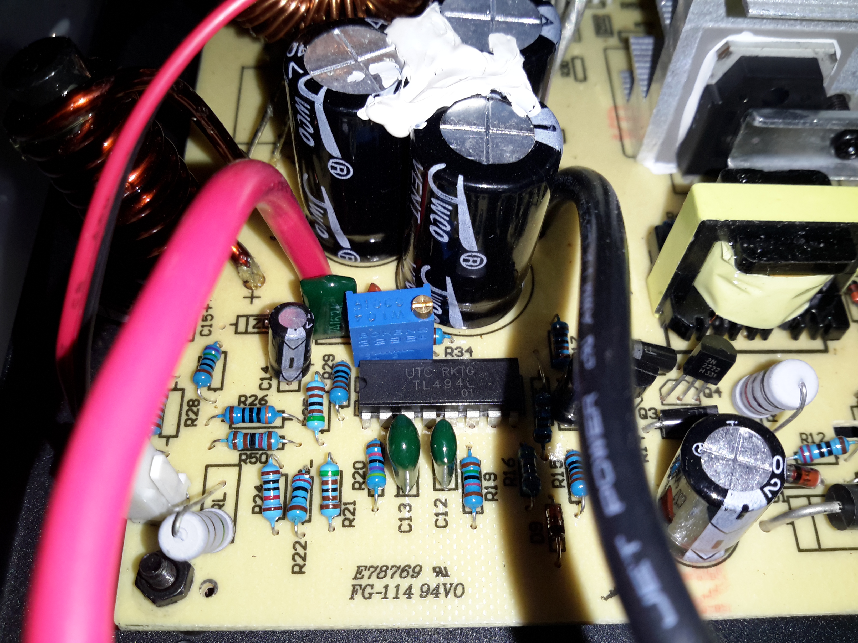
SMPS Controller
The supply is controlled via the jelly bean TL494 PWM controller IC. The multi-turn potentiometer doesn’t adjust the output voltage, more likely it adjusts the current limit.
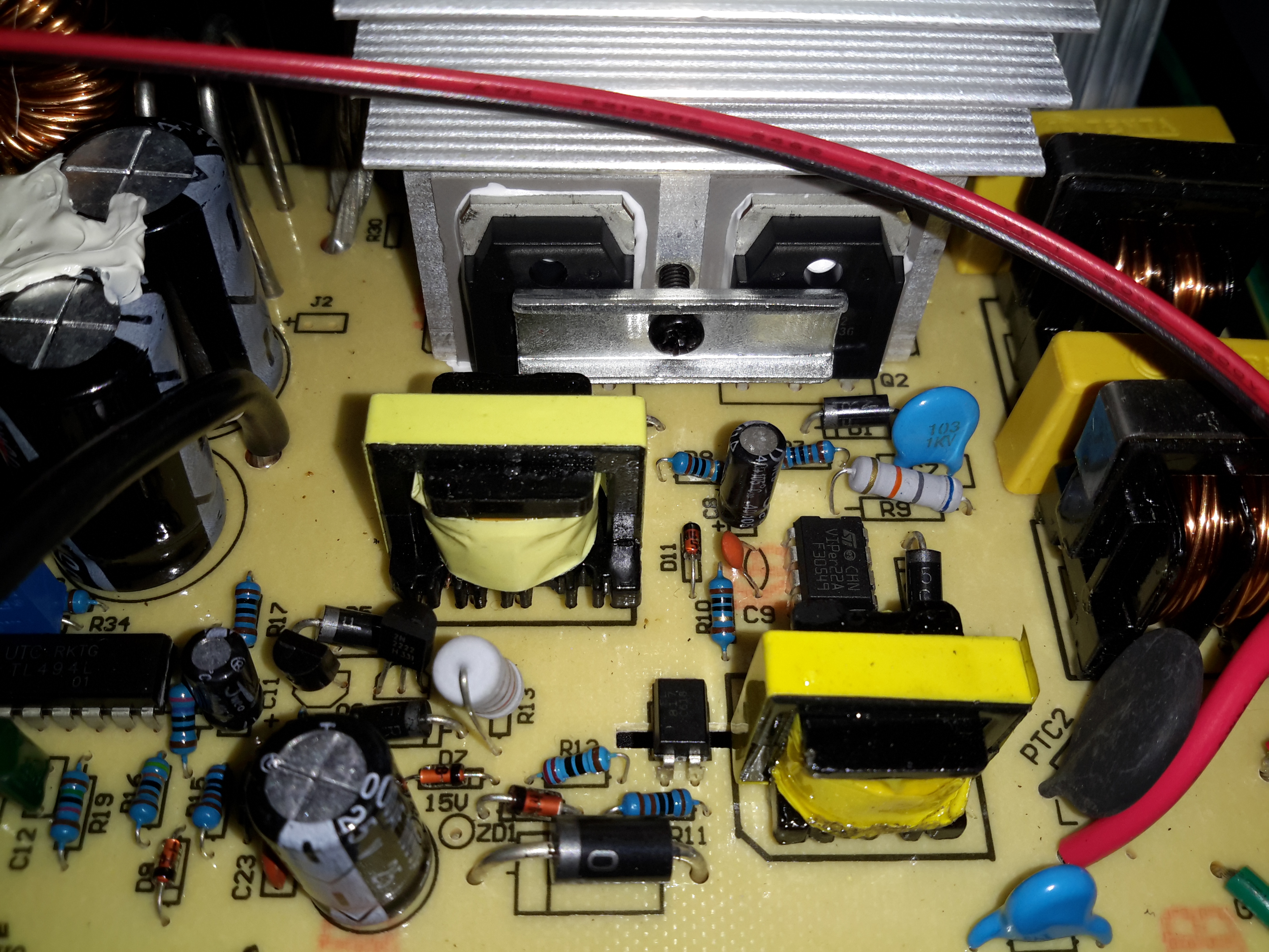
Standby Supply
Power to initially start the supply is provided by a small SMPS circuit, with a VIPer22A Low Power Primary Switcher & small transformer on the lower right. The transformer upper left is the base drive transformer for the main high power supply.
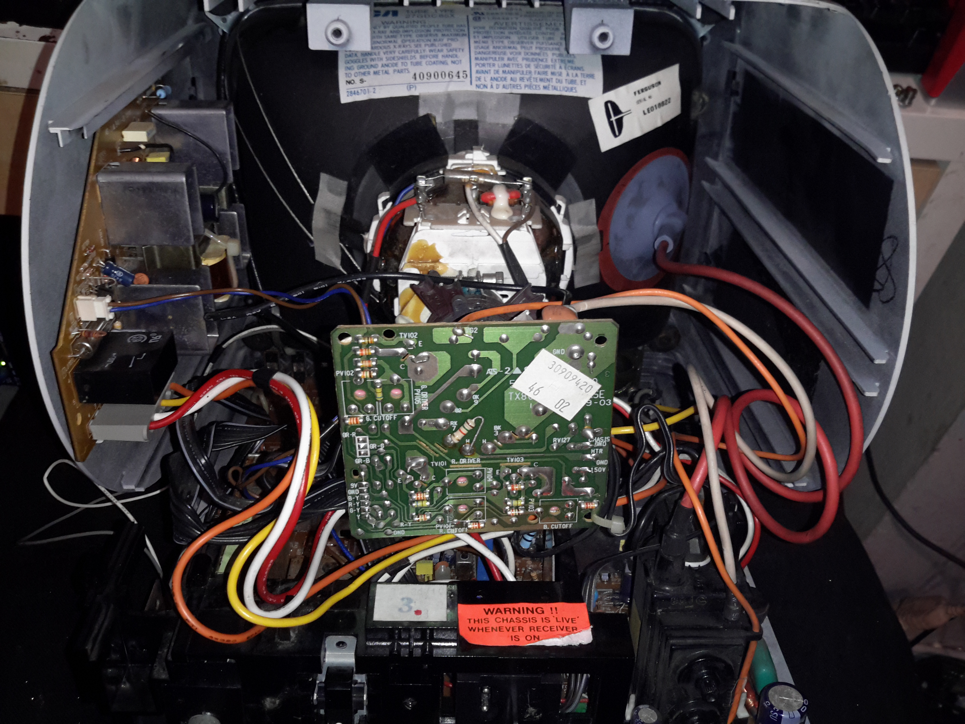
Here’s the other TV that was picked up from the local water point having been put of to be recycled. This one is much newer than the Thorn TV, a 10″ colour version from Ferguson.
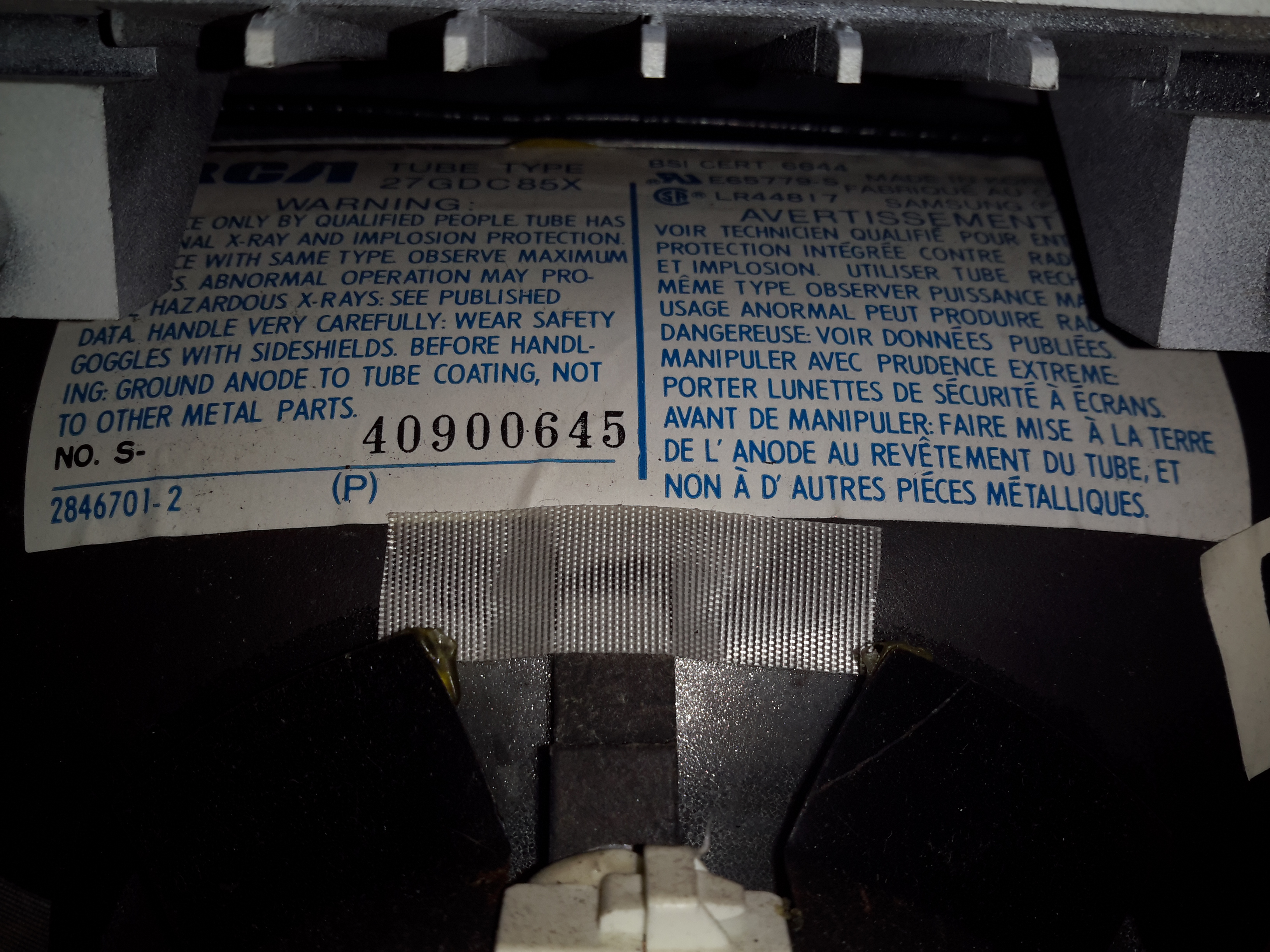
RCA 27GDC85X CRT
The colour CRT used is an RCA branded one, 27GDC85X.
Power Inputs
Like the other TV, this one is dual voltage input, mains 240v & 12v battery. This TV is a factory conversion of a standard 240v AC chassis though.
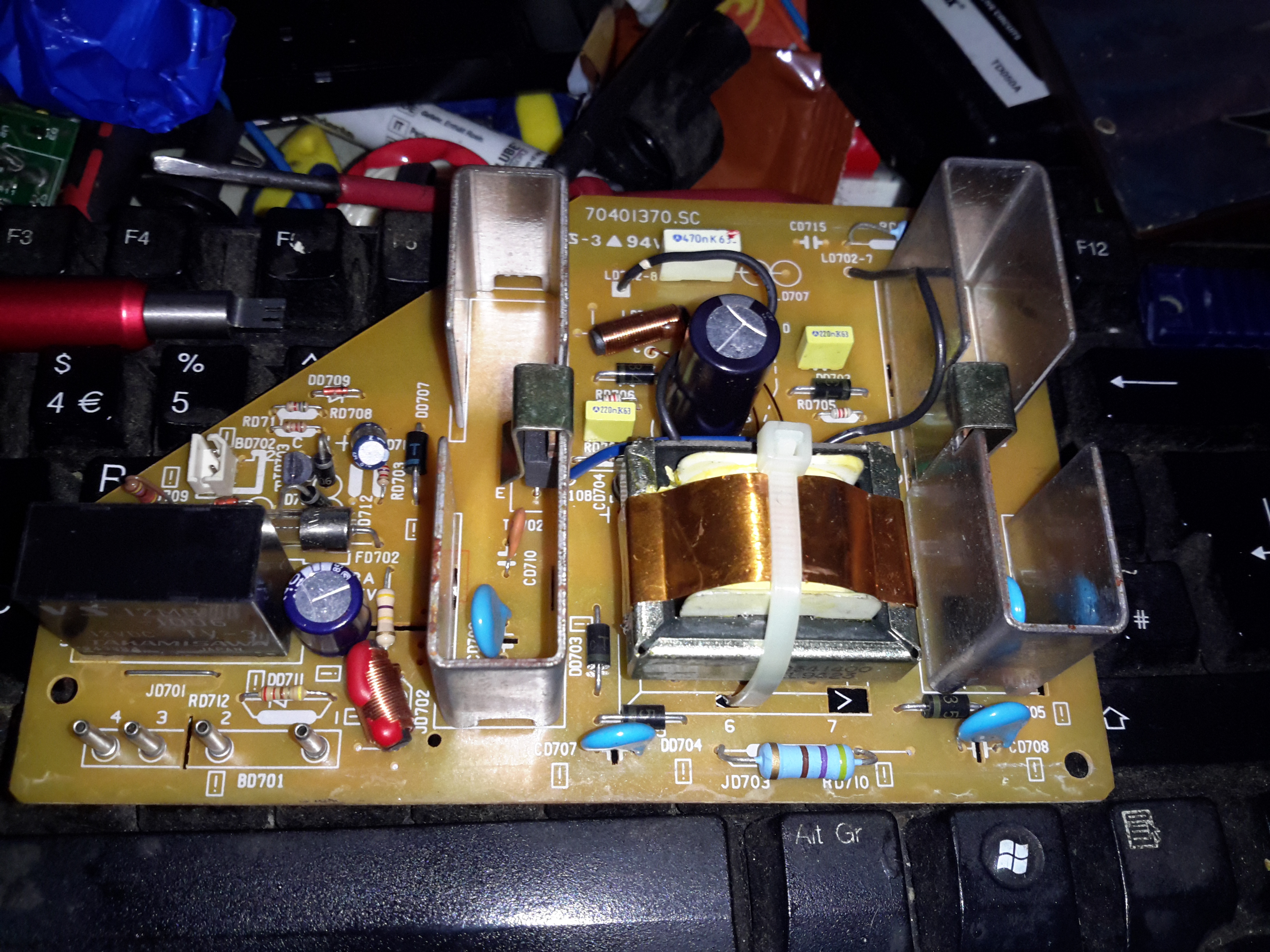
HV PSU
The 12v power first goes into this board, which looked suspiciously like an inverter. Measuring on the output pins confirmed I was right, this addon board generates a 330v DC supply under a load, but it’s not regulated at all, under no load the output voltage shoots up to nearly 600v!
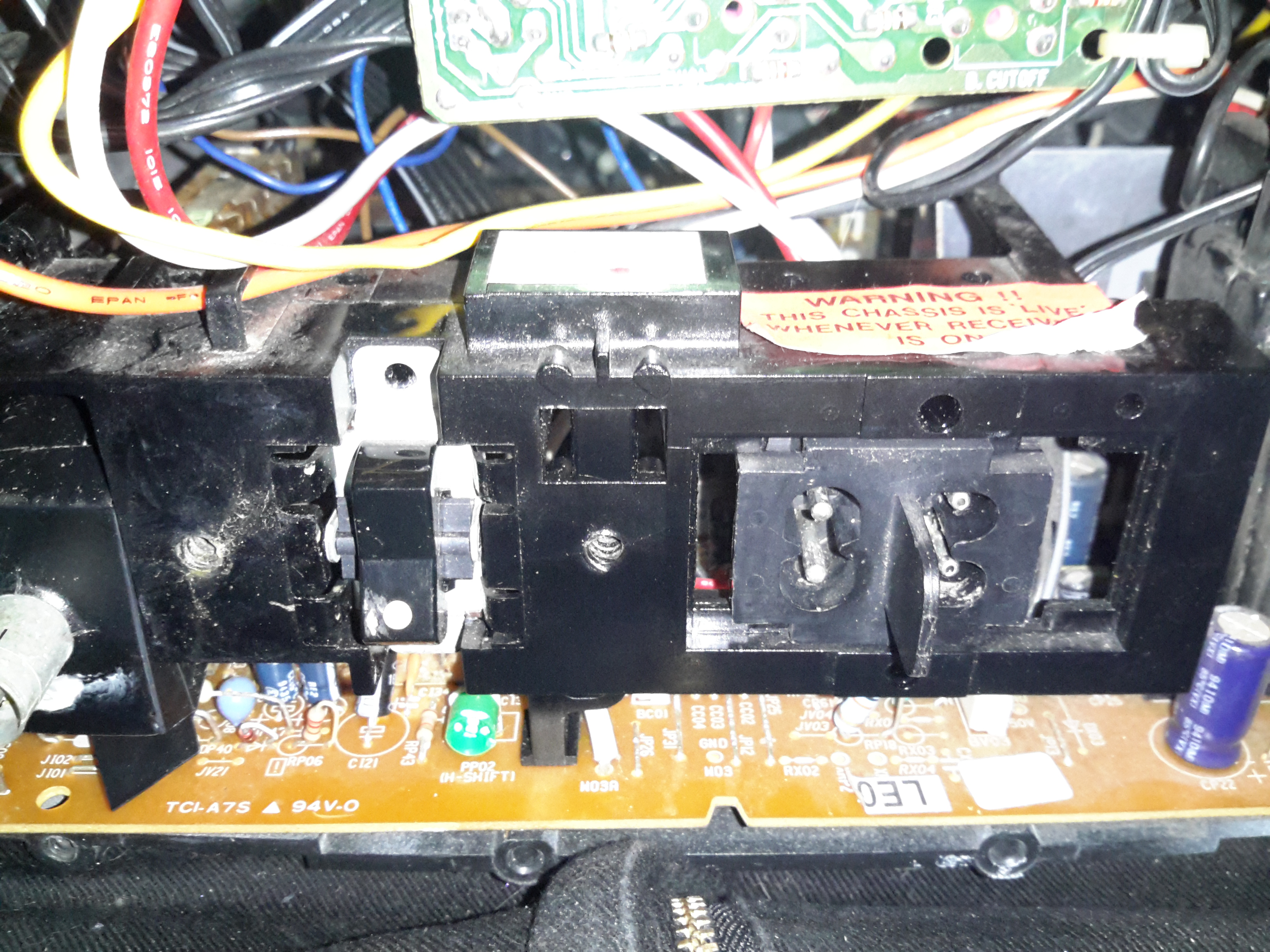
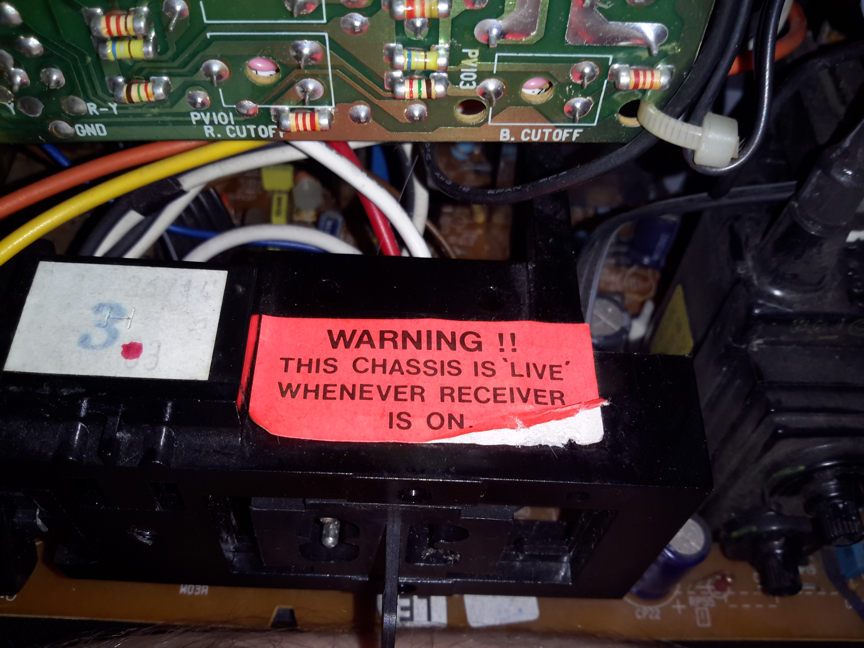
Live Chassis
I’ve not seen one of these labels on a TV for many years, when back in the very old TV sets the steel chassis would be used to supply power to parts of the circuitry, to save on copper. Although it doesn’t have a metal chassis to actually become live, so I’m not sure why it’s here.
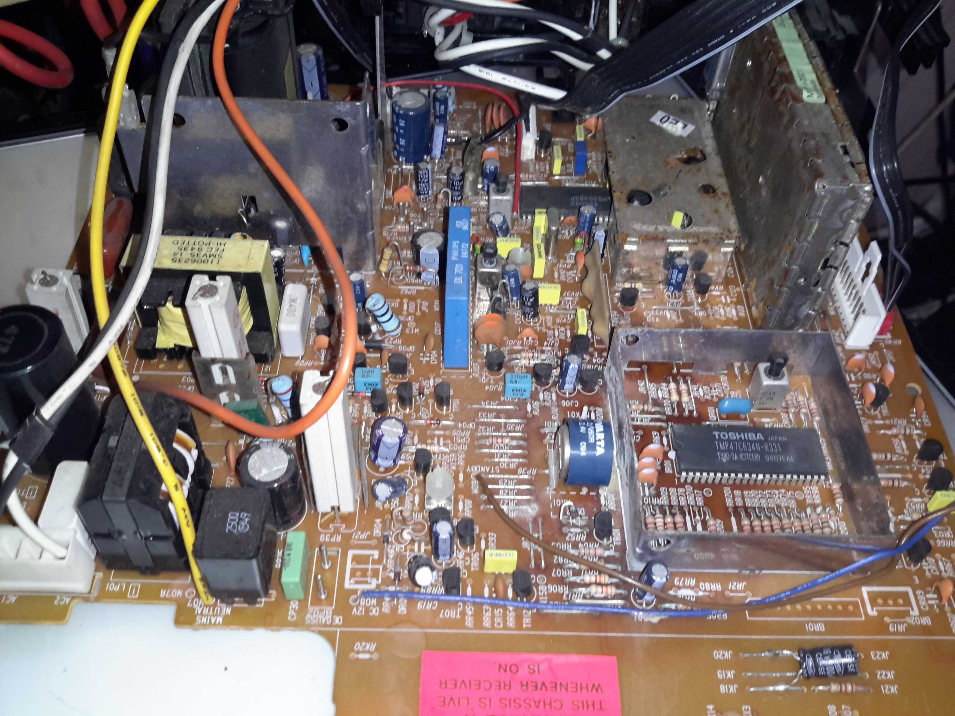
Main PCB
The main PCB is much more integrated in this newer TV, from the mid 90’s, everything is pretty much taken care of by silicon by this point.
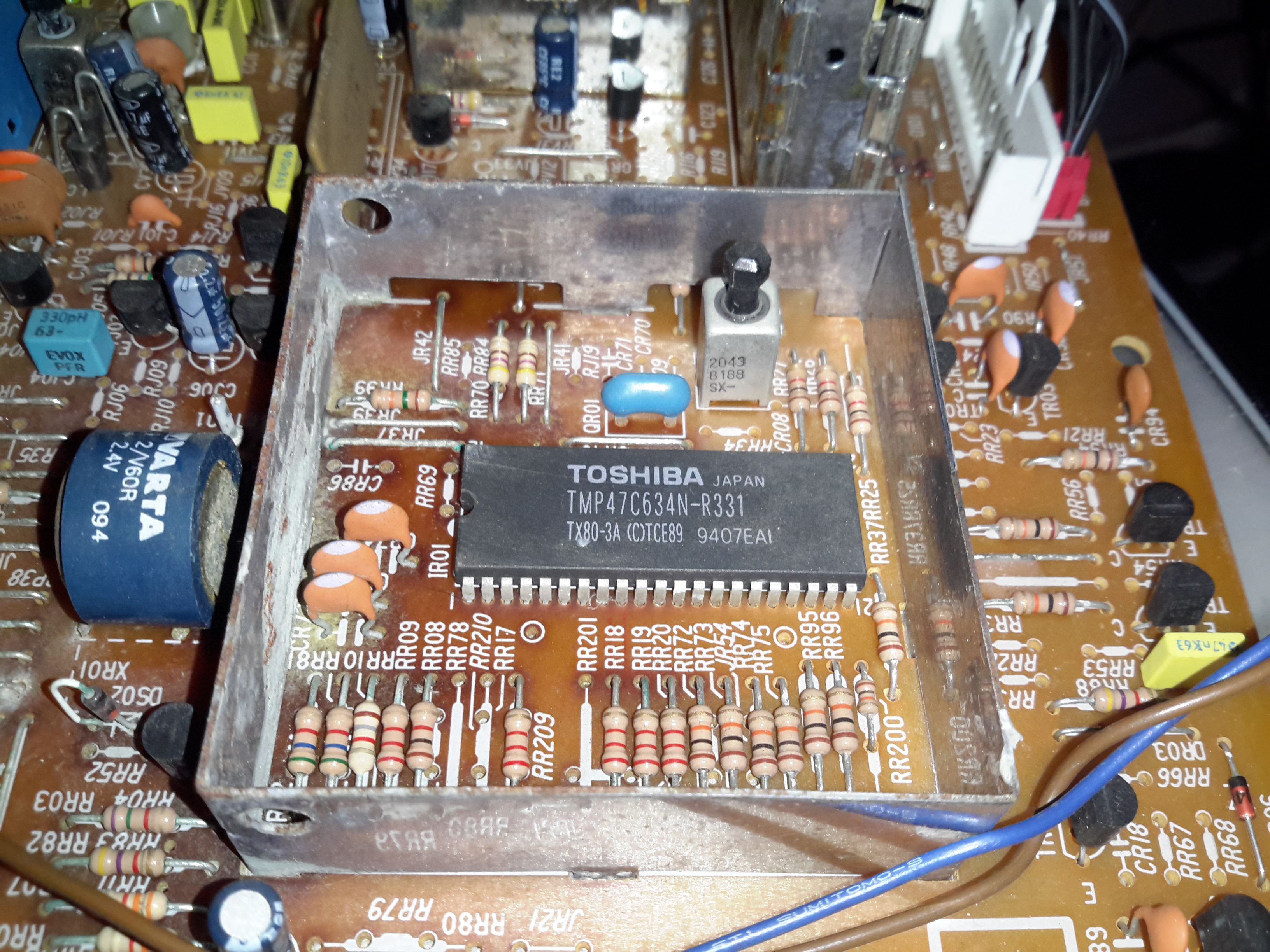
Main Microcontroller
This Toshiba µC takes care of channel switching & displaying information on the CRT. The tuner in this TV is electronically controlled.
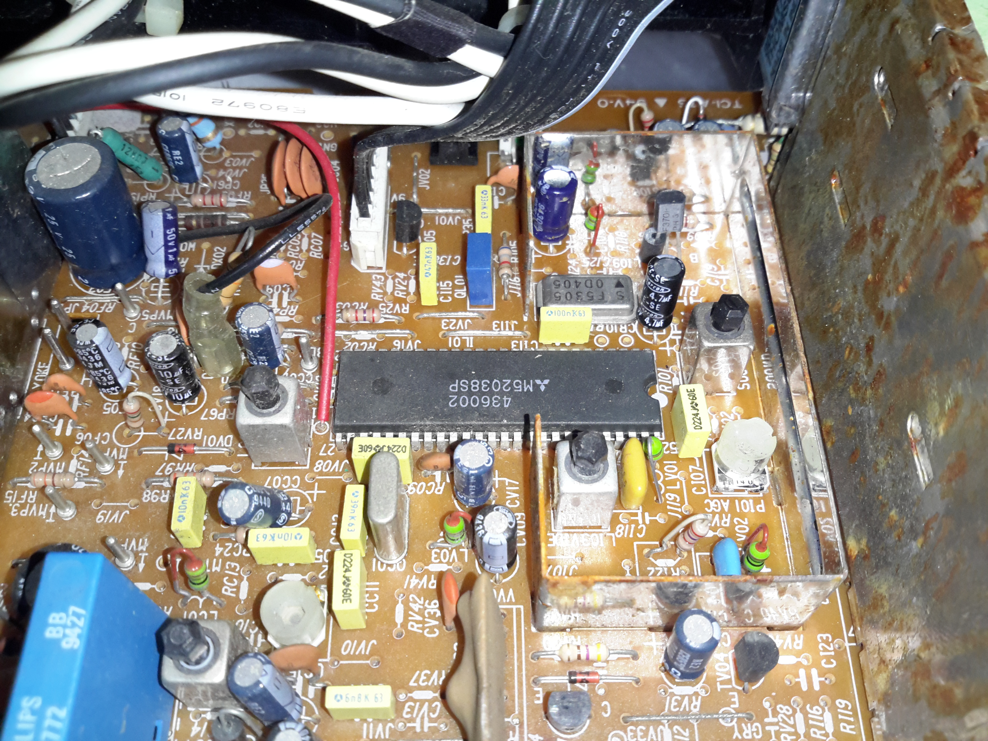
PAL Signal Processor
The video signal is handled by this Mitsubishi IC, which is a PAL Signal Processor, this does Video IF, Audio IF, Chroma, & generates the deflection oscillators & waveforms to drive the yoke.
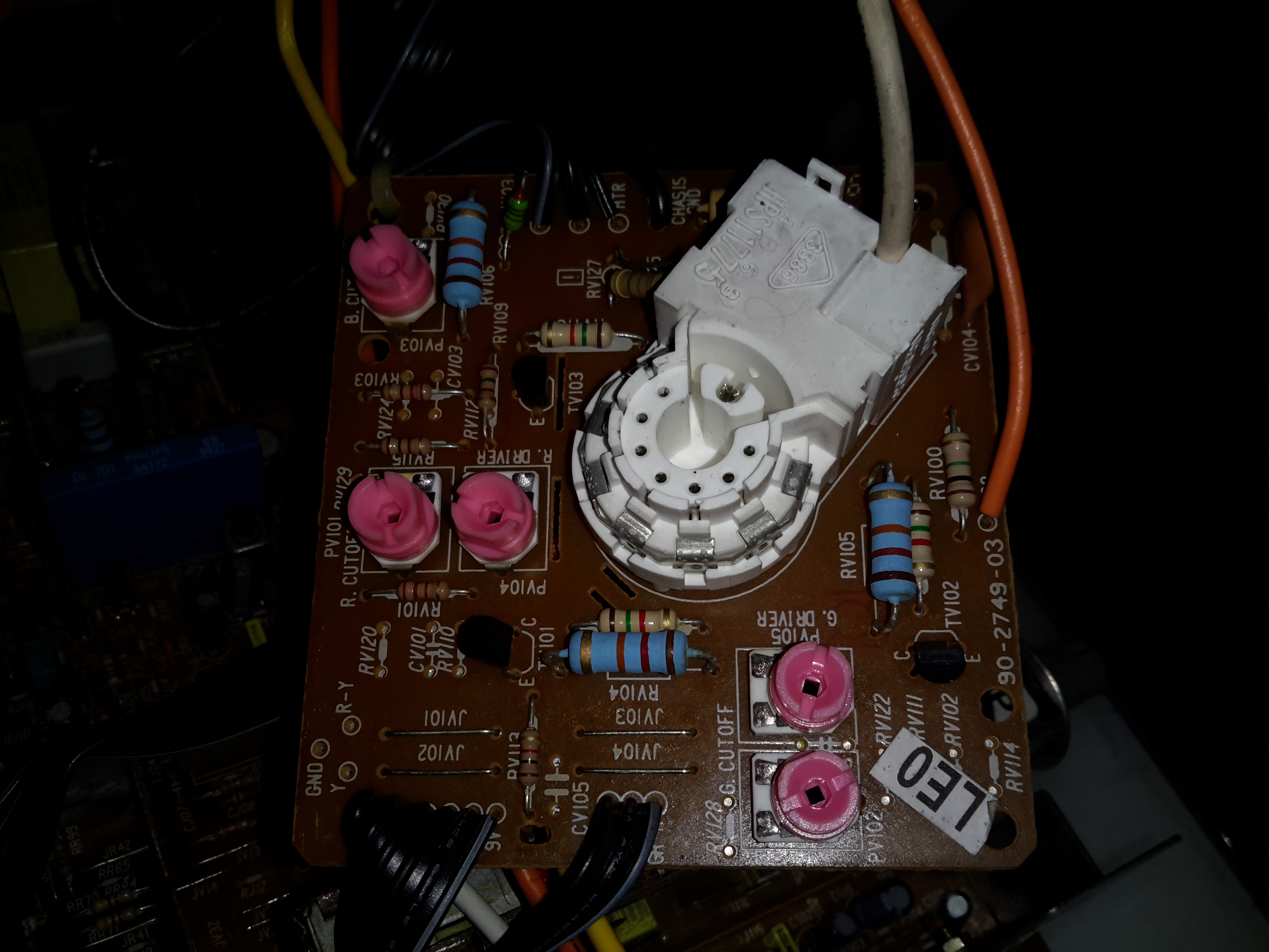
CRT Adjustments
There are some adjustments on the CRT neck board for RGB drive levels & cutoff levels. This board also had the final video amplifiers onboard, which drive the CRT cathodes.
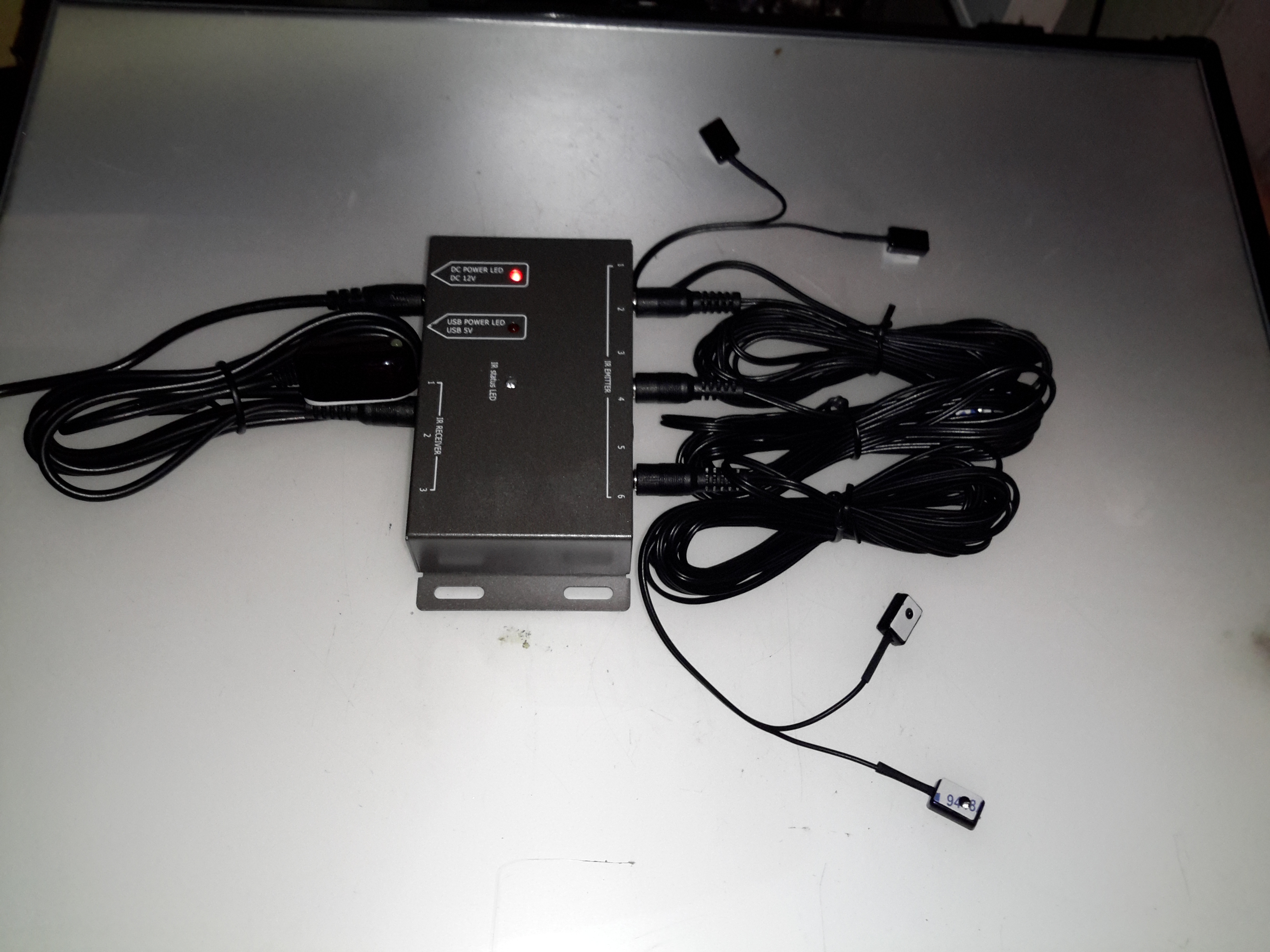
Here’s another random gadget for teardown, this time an IR remote control repeater module. These would be used where you need to operate a DVD player, set top box, etc in another room from the TV that you happen to be watching. An IR receiver sends it’s signal down to the repeater box, which then drives IR LEDs to repeat the signal.
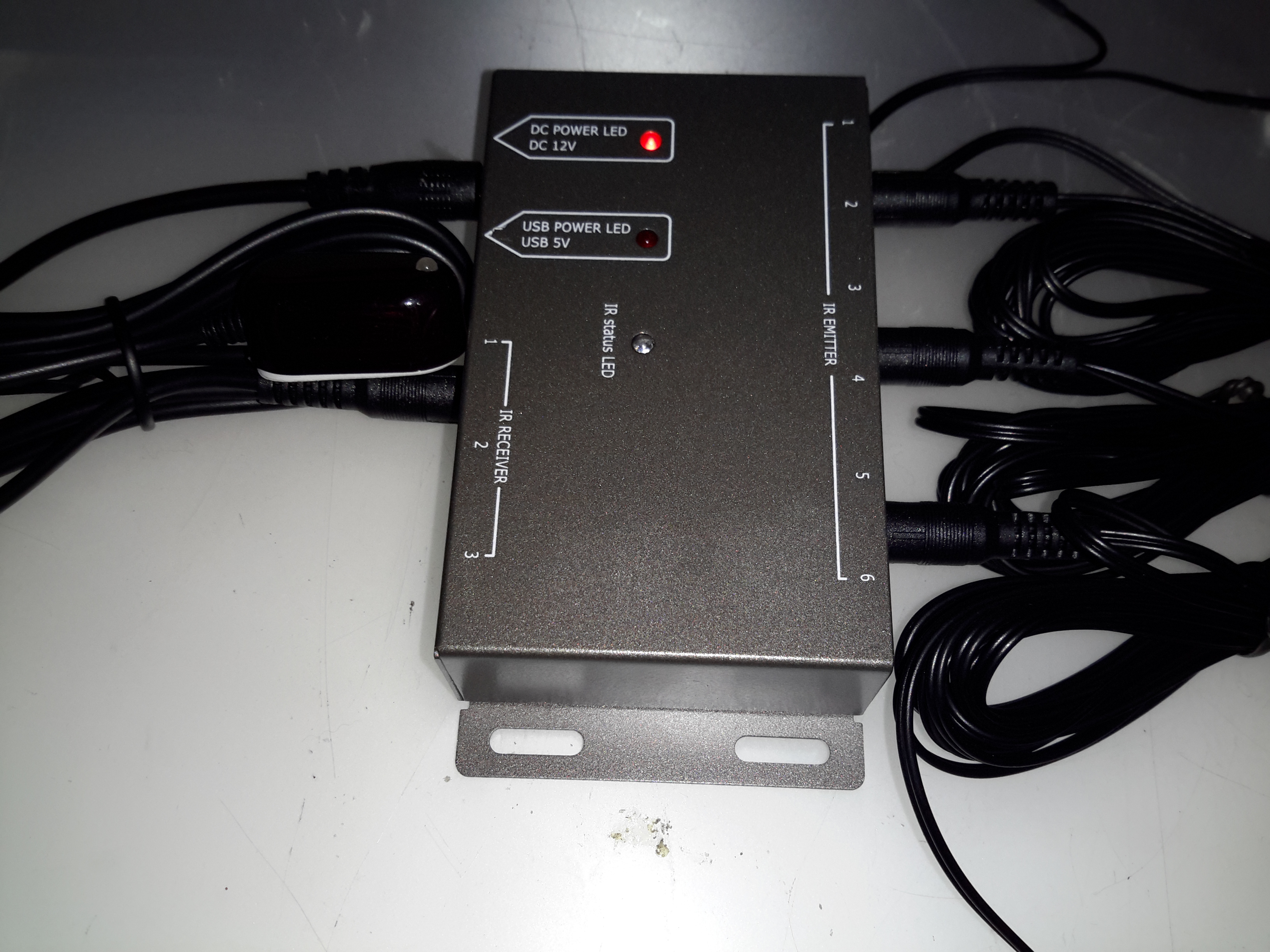
Repeater Module
Not much to day about the exterior of this module, the IR input is on the left, up to 3 receivers can be connected. The outputs are on the right, up to 6 repeater LEDs can be plugged in. Connections are done through standard 3.5mm jacks.
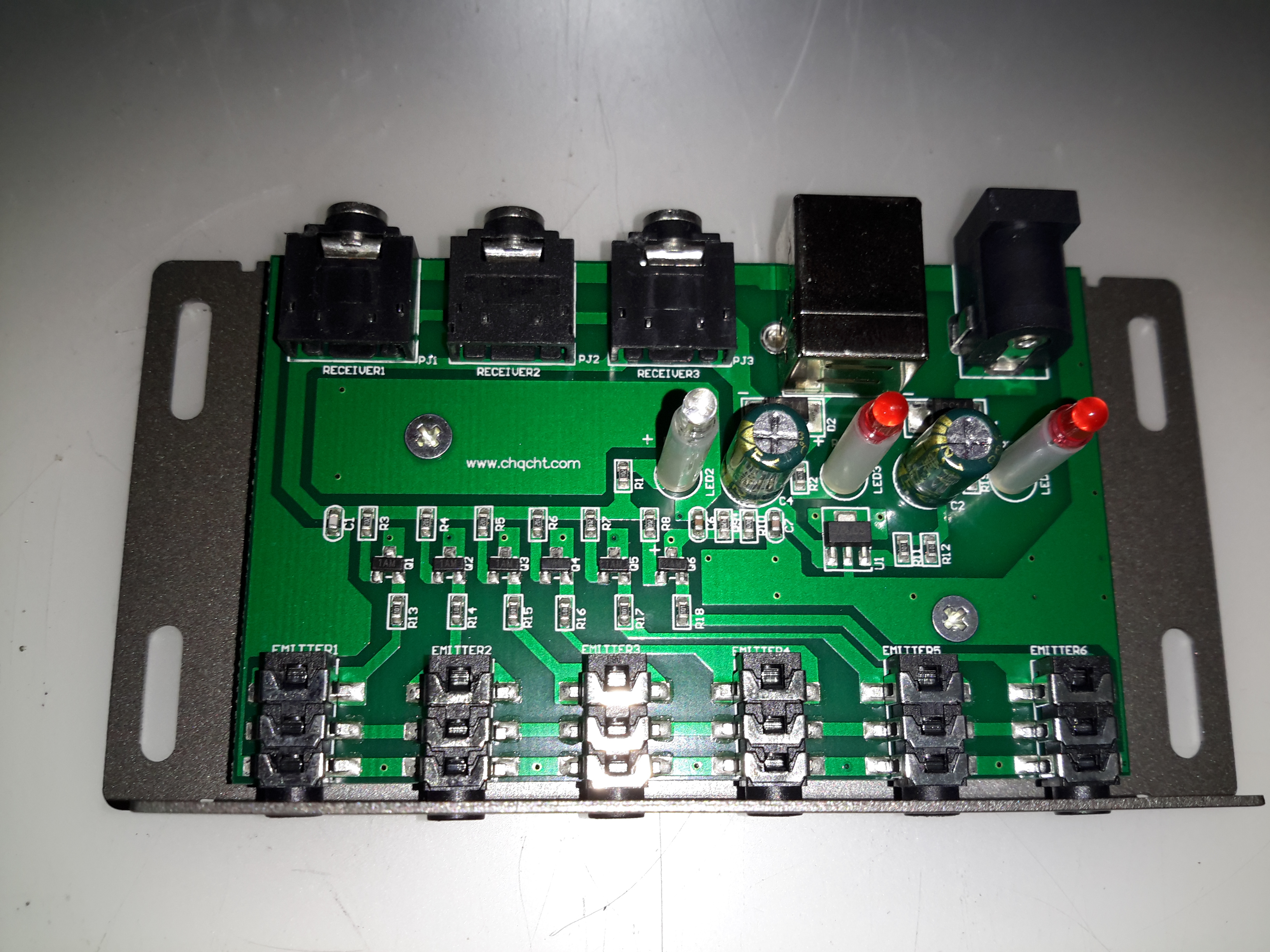
Repeater PCB
Not much inside this one at all, there are 6 transistors which each drive an LED output. This “dumb” configuration keeps things very simple, no signal processing has to be done. Power is either provided by a 12v input, which is fed into a 7805 linear regulator, or direct from USB.
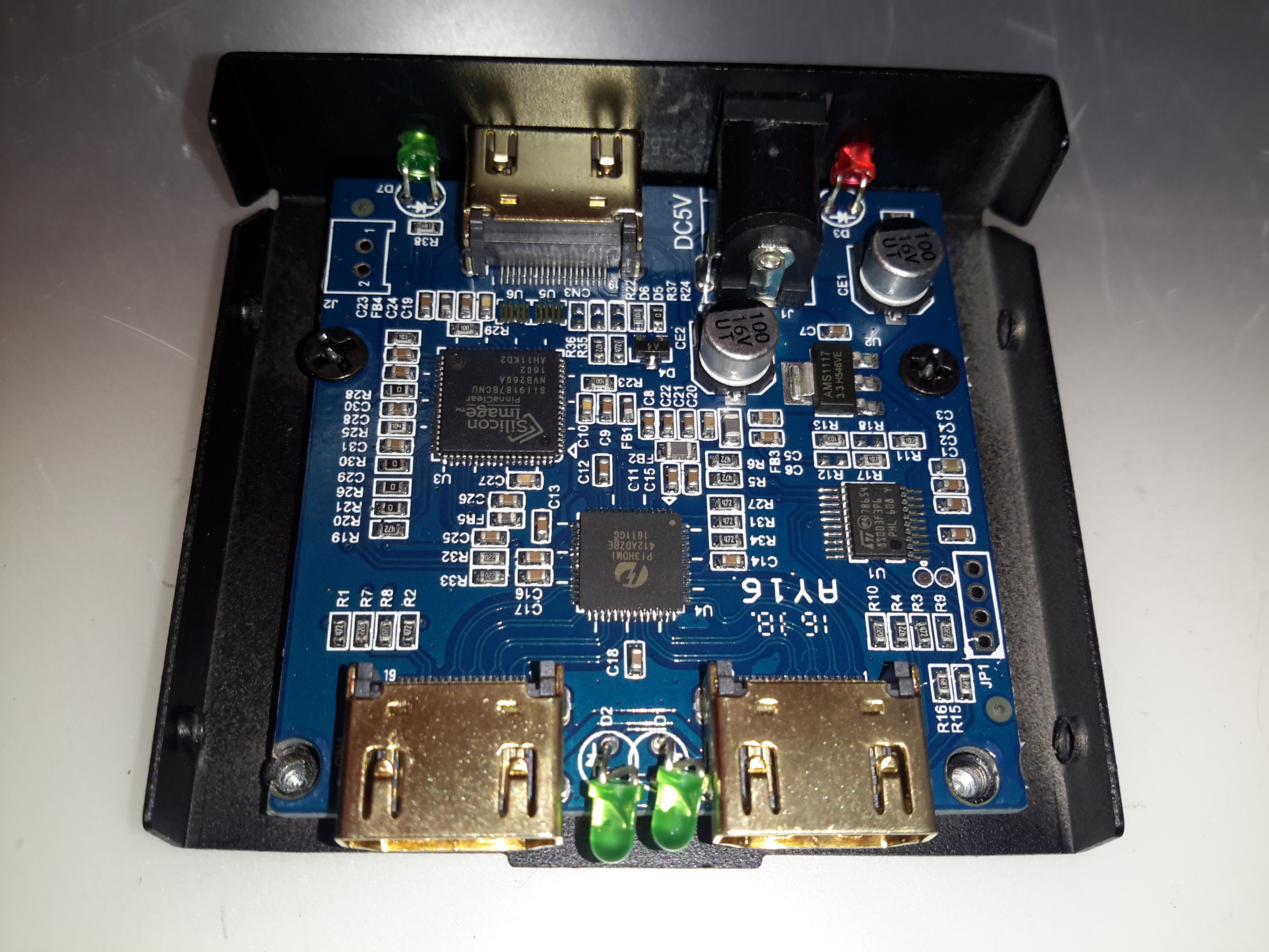
Time for another random teardown, a signal splitter for HDMI. These units are available very cheap these days on eBay. This one splits the incoming signal into two to drive more than one display from the same signal source.
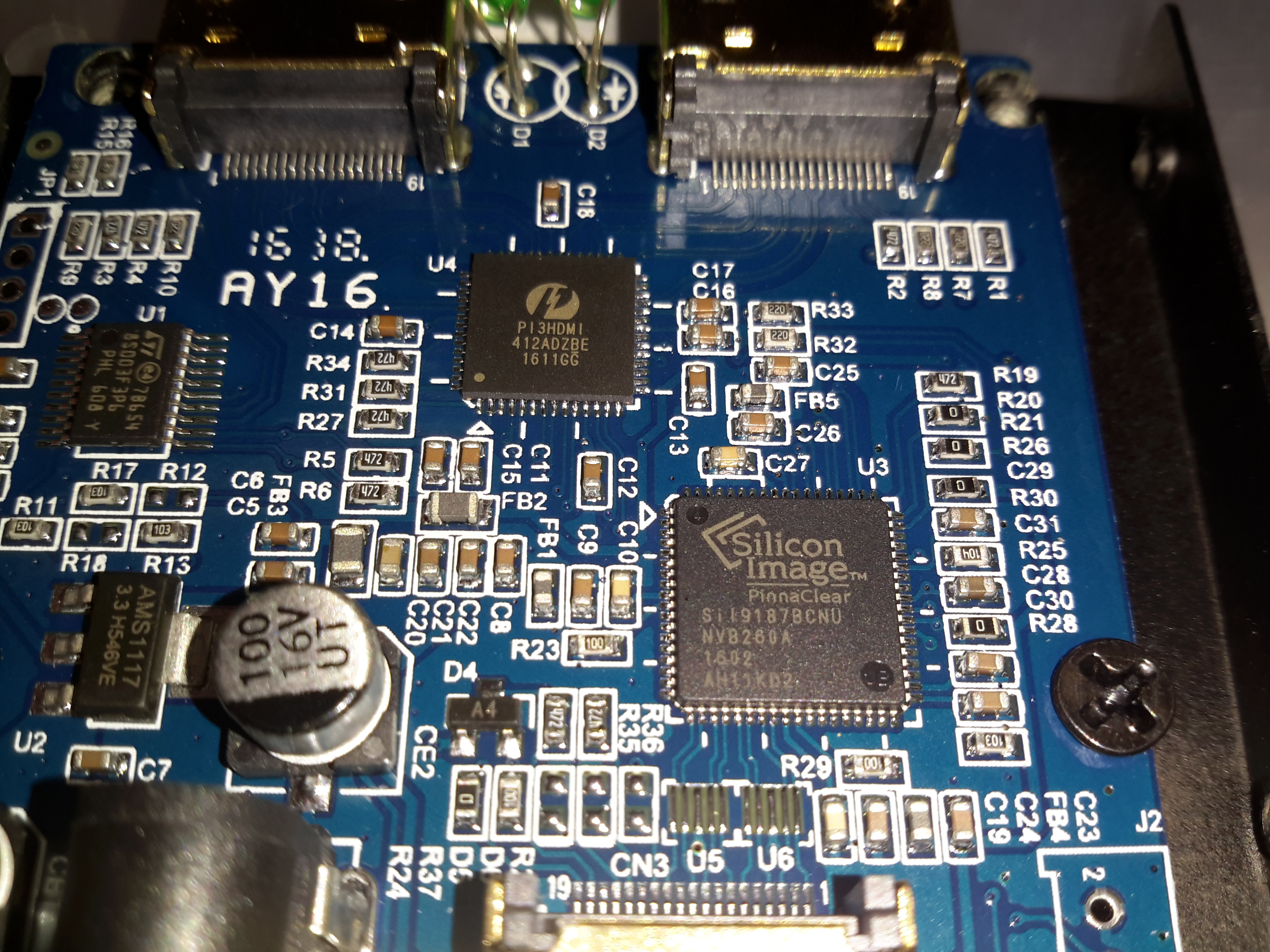
Main PCB
The stamped alloy casing comes apart easily with the removal of a few screws. The PCB inside is rather densely packed with components.
Chipset
The main IC on the incoming signal is a Silicon Image Sil9187B HDMI Port Processor, with a single input & 4 outputs. In this case the chip is used as a repeater to amplify the incoming signal. the signal path then gets fed into a Pericom PI3HDMI412 HDMI Demux, which then splits the signal into two for the output ports.
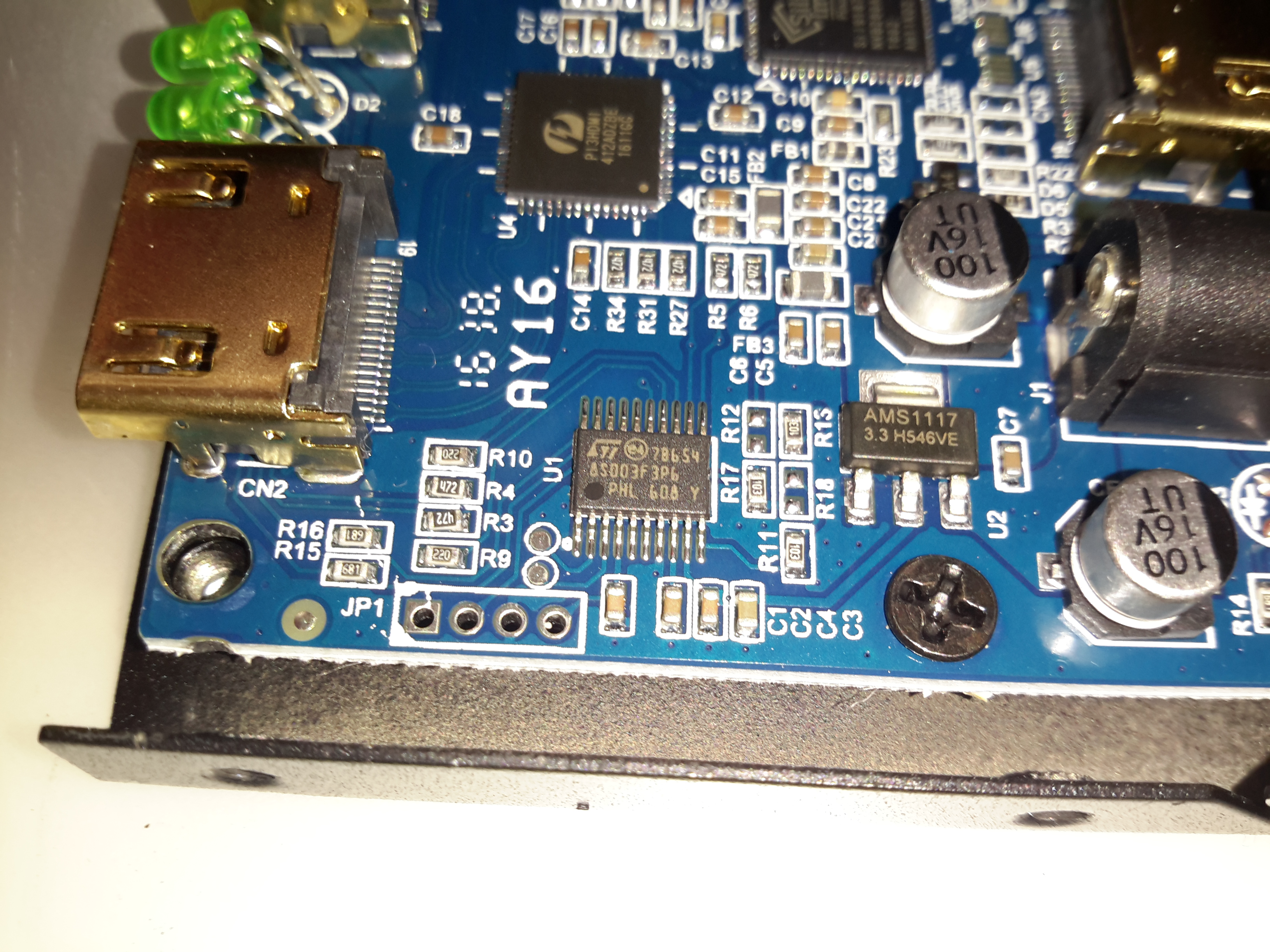
Microcontroller
The main pair of ICs processing the video signals are controlled over I²C, with this STM32 microcontroller. The 4 pads to the lower left are for the STLink programmer. The main 3.3v power rail is provided by the LM1117 linear regulator on the right.
Time foe some more retro tech! This is a 1980’s vintage CCD-based VHS camcorder from Panasonic, the NV-M5. There are a lot of parts to one of these (unlike modern cameras), so I’ll split this post into several sections to make things easier to read (and easier to keep track of what I’m talking about :)).
Left Side
The left side of the camera holds the autofocus, white balance, shutter speed & date controls.
Left Side ControlsLens Adjustments
The lens is fully adjustable, with either manual or motorized automatic control.
Rear Panel
The back panel has the battery slot, a very strange looking DC input connector, remote control connector & the earphone jack.
Top Controls
The top panel of the camera holds the main power controls, manual tape tracking & the tape transport control panel.
Viewfinder
The viewfinder is mounted on a swivel mount. There’s a CRT based composite monitor in here. Hack ahoy!
Camera Section
Process Board Assembly
Here’s the camera section of the camcorder, and is totally packed with electronics! There’s at least half a dozen separate boards in here, all fitted together around the optics tube assembly.
AWB PCB
On the top of the assembly is the Automatic White Balance PCB. Many adjustments here to get everything set right. Not much on the other side of this board other than a bunch of Op-Amps. The iris stepper motor is fitted in a milled opening in the PCB, this connects to one of the other PCBs in the camera module.
AWB Sensor
Here’s the AWB sensor, mounted next to the lens. I’m not all to certain how this works, but the service manual has the pinout, and there are outputs for all the colour channels, RGB. So it’s probably a trio of photodiodes with filters.
Focus & Zoom Motors
Focus & Zoom are controlled with a pair of DC gear motors. The manual operation is feasible through the use of slip clutches in the final drive pinion onto the lens barrel.
Process Board
The main camera section process board is above. This board does all the signal processing for the CCD, has the bias voltage supplies and houses the control sections for the motorized parts of the optics assembly. There are quite a few dipped Tantalum capacitors on pigtails, instead of being directly board mounted. This was probably done due to space requirements on the PCB itself.
Under the steel shield on this board is some of the main signal processing for the CCD.
Optics Assembly
The back of the optics tube is a heavy casting, to supress vibration. This will be more clear later on.
Position Sensor Flex
The position of the lens elements is determined by reflective strips on the barrel & sensors on this flex PCB.
Sub Process Board
There’s another small board tucked into the side of the tube, this hooks into the process PCB.
Process Delay Line
According to the schematic, there’s nothing much on this board, just a delay line & a few transistors.
Piezo Focus Disc
Here’s the reason for the heavy alloy casing at the CCD mounting end of the optics: the fine focus adjustment is done with a piezoelectric disc, the entire CCD assembly is mounted to this board. Applying voltage to the electrodes moves the assembly slightly to alter the position of the CCD. The blue glass in the centre of the unit is the IR filter.
IR Relective Sensors
The barrel position sensors are these IR-reflective type.
Iris Assembly
The iris is mounted just before the CCD, this is controlled with a galvanometer-type device with position sensors incorporated.
Iris Opening
Pushing on the operating lever with the end of my screwdriver opens the leaves of the iris against the return spring.
Tape Transport & Main Control
Main Control Board
Tucked into the side of the main body of the unit is the main system control board. This PCB houses all the vital functions of the camera: Power Supply, Servo Control, Colour Control,Video Amplifiers, etc.
Tape Drum
Here’s the main tape transport mechanism, this is made of steel & aluminium stampings for structural support. The drum used in this transport is noticeably smaller than a standard VHS drum, the tape is wrapped around more of the drum surface to compensate.
Tape Transport
The VHS tape sits in this carriage & the spools drive the supply & take up reels in the cartridge.
Main Control PCB
Here’s the component side of the main control PCB. This one is very densely packed with parts, I wouldn’t like to try & troubleshoot something like this!
Main PCB Left
The left side has the video head amp at the top, a Panasonic AN3311K 4-head video amp. Below that is video processing, the blue components are the analogue delay lines. There are a couple of hybrid flat-flex PCBs tucked in between with a couple of ICs & many passives. These hybrids handle the luma & chroma signals.
Top left is the capstan motor driver a Rohm BA6430S. The transport motors are all 3-phase brushless, with exception of the loading motor, which is a brushed DC type.
Delay Line
Here’s what is inside the delay lines for the analogue video circuits. The plastic casing holds a felt liner, inside which is the delay line itself.
Internal Glass
The delay is created by sending an acoustic signal through the quartz crystal inside the device by a piezoelectric transducer, bouncing it off the walls of the crystal before returning it to a similar transducer.
Main PCB Centre
Here’s the centre of the board, the strange crystal at bottom centre is the clock crystal for the head drum servo. Why it has 3 pins I’m not sure, only the two pins to the crystal inside are shown connected on the schematic. Maybe grounding the case?
The main servo controls for the head drum & the capstan motor are top centre, these get a control signal from the tape to lock the speed of the relative components.
Main PCB Right
Here’s the right hand side. The main power supply circuitry is at top right, with a large can containing 4 switching inductors & a ferrite pot core transformer. All these converters are controlled by a single BA6149 6-channel DC-DC converter controller IC via a ULN2003 transistor array.
The ceramic hybrid board next to the PSU has 7 switch transistors for driving various indicator LEDs.
The large tabbed IC bottom centre is the loading motor drive, an IC from Mitsubishi, the M54543. This has bidirectional DC control of the motor & built in braking functions. The large quad flat pack IC on the right is the MN1237A on-screen character generator, with the two clock crystals for the main microcontroller.
Erase Head
The full erase head has it’s power supply & oscillator on board, applying 9v to this board results in an AC signal to the head, which erases the old recording from the tape before the new recording is laid down by the flying heads on the drum.
Audio Control PCB
The Audio & Control head is connected to this PCB, which handles both reading back audio from the tape & recording new audio tracks. The audio bias oscillator is on this board, & the onboard microphone feeds it’s signal here. The control head is fed directly through to the servo section of the main board.
Drum Motor
The motor that drives the head drum is another DC brushless 3-phase type.
Hall Sensors
These 3 Hall sensors are used by the motor drive to determine the rotor position & time commutation accordingly.
Stator
The stator on this motor is of interesting construction, with no laminated core, the coils are moulded into the plastic holder. The tach sensor is on the side of the stator core. This senses a small magnet on the outside of the rotor to determine rotational speed. For PAL recordings, the drum rotates at 1500 RPM.
Motor Removed
Not much under the stator other than the bearing housing & the feedthrough to the rotary transformer.
Head Disc
The heads are mounted onto the top disc of the drum, 4 heads in this recorder. The signals are transmitted to the rotating section through the ferrite rotary transformer on the bottom section.
Head Chip
The tiny winding of the ferrite video head can just about be seen on the end of the brass mounting.
Capstan Motor Components
The capstan motor is similar to the drum motor, only this one is flat. The rotor has a ferrite magnet, in this case it wasn’t glued in place, just held by it’s magnetic field.
Capstan Motor Stator
The PCB on this motor has a steel backing to complete the magnetic circuit, the coils for the 3 motor phases are simply glued in place. The Hall sensors on this motor are placed in the middle of the windings though.
Again there is a tach sensor on the edge of the board that communicates the speed back to the controller. This allows the servo to remain locked at constant speed.
Viewfinder
Viewfinder Assembly
As usual with these cameras, this section is the CRT based viewfinder. These units take the composite signal from the camera to display the scene. This one has many more pins than the usual viewfinder. I’ll hack a manual input into this, but I’ll leave that for another post.
Viewfinder Circuits
Being an older camera than the ones I’ve had before, this one is on a pair of PCBs, which are both single-sided.
Main Viewfinder Board
The main board has all the power components for driving the CRT & some of the adjustments. The main HV flyback transformer is on the right. This part creates both the final anode voltage for the tube & the focus/grid voltages.
Viewfinder Control PCB Top
The viewfinder control IC is on a separate daughter board in this camera, with two more controls.
Control IC
The control IC is a Matsushita AN2510S, this has all the logic required to separate the sync pulses from the composite signal & generate an image on the CRT.
Viewfinder CRT Frame
The recording indicator LEDs are mounted in the frame of the CRT & appear above the image in the viewfinder.
Viewfinder CRT With Yoke
Here the CRT has been separated from the rest of the circuitry with just the deflection yoke still attached.
M01JPG5WB CRT
The electron gun in this viewfinder CRT is massive in comparison to the others that I have seen, and the neck of the tube is also much wider. These old tubes were very well manufactured.
Viewfinder Optics
A simple mirror & magnifying lens completes the viewfinder unit.
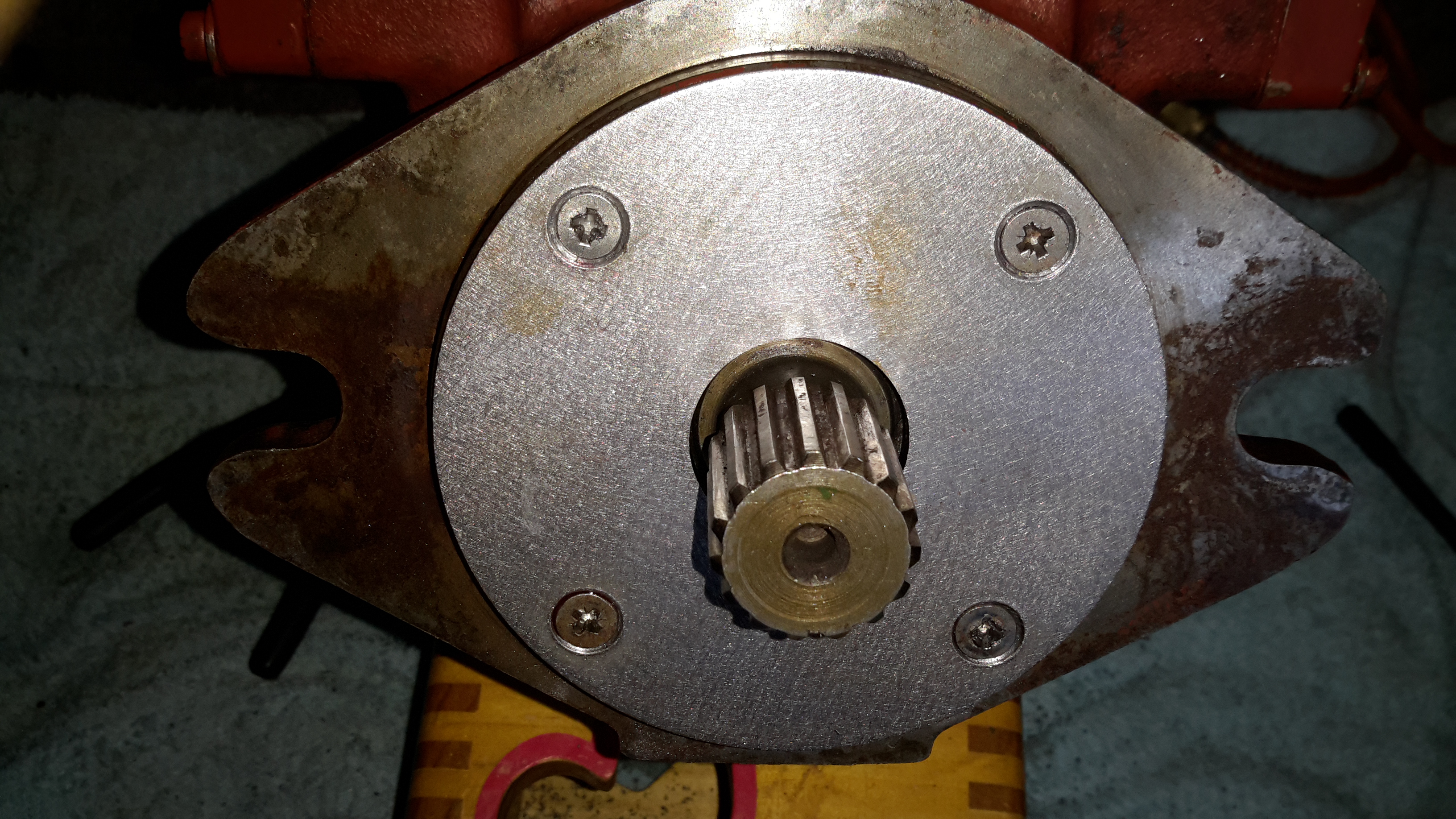
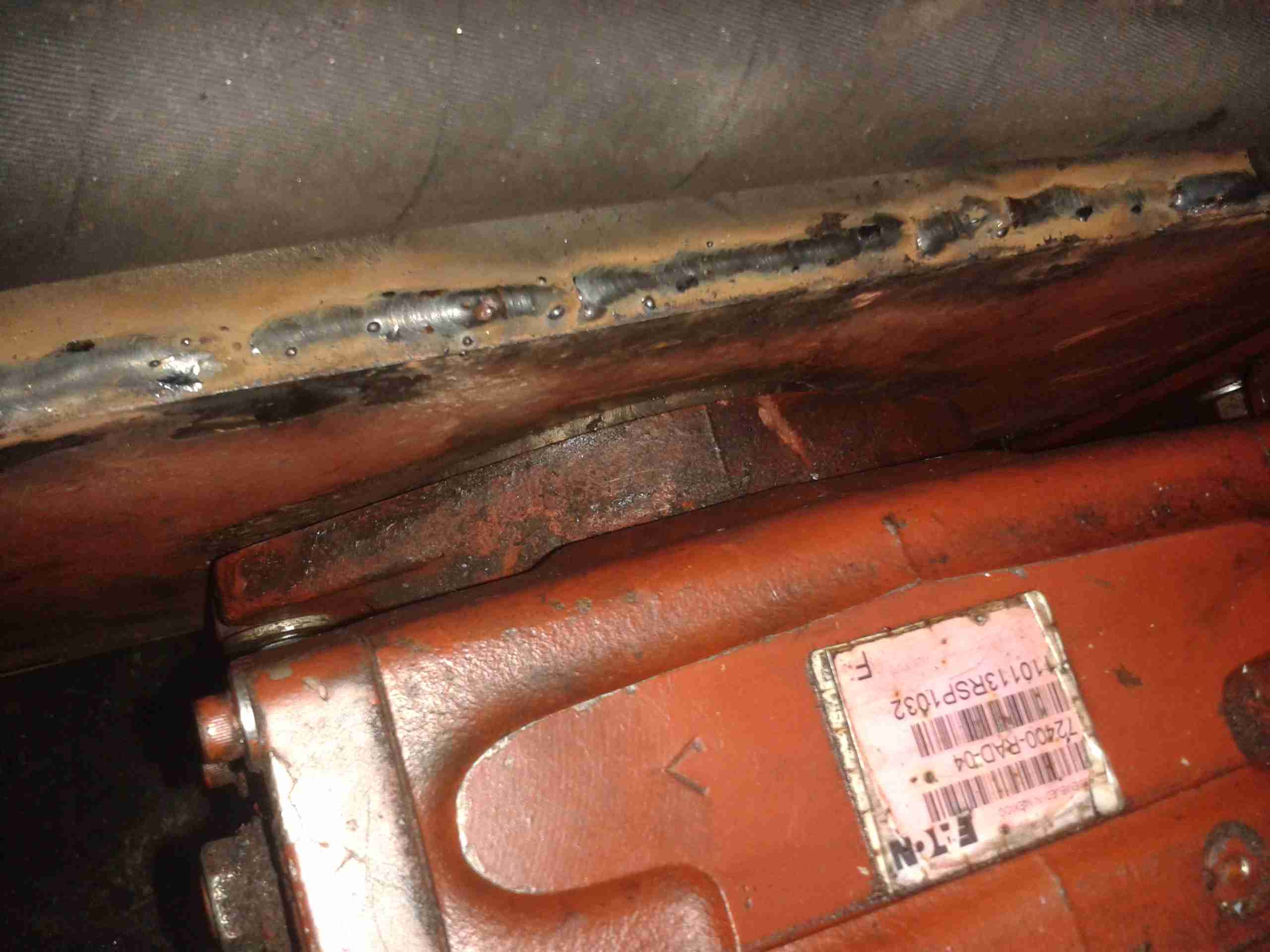
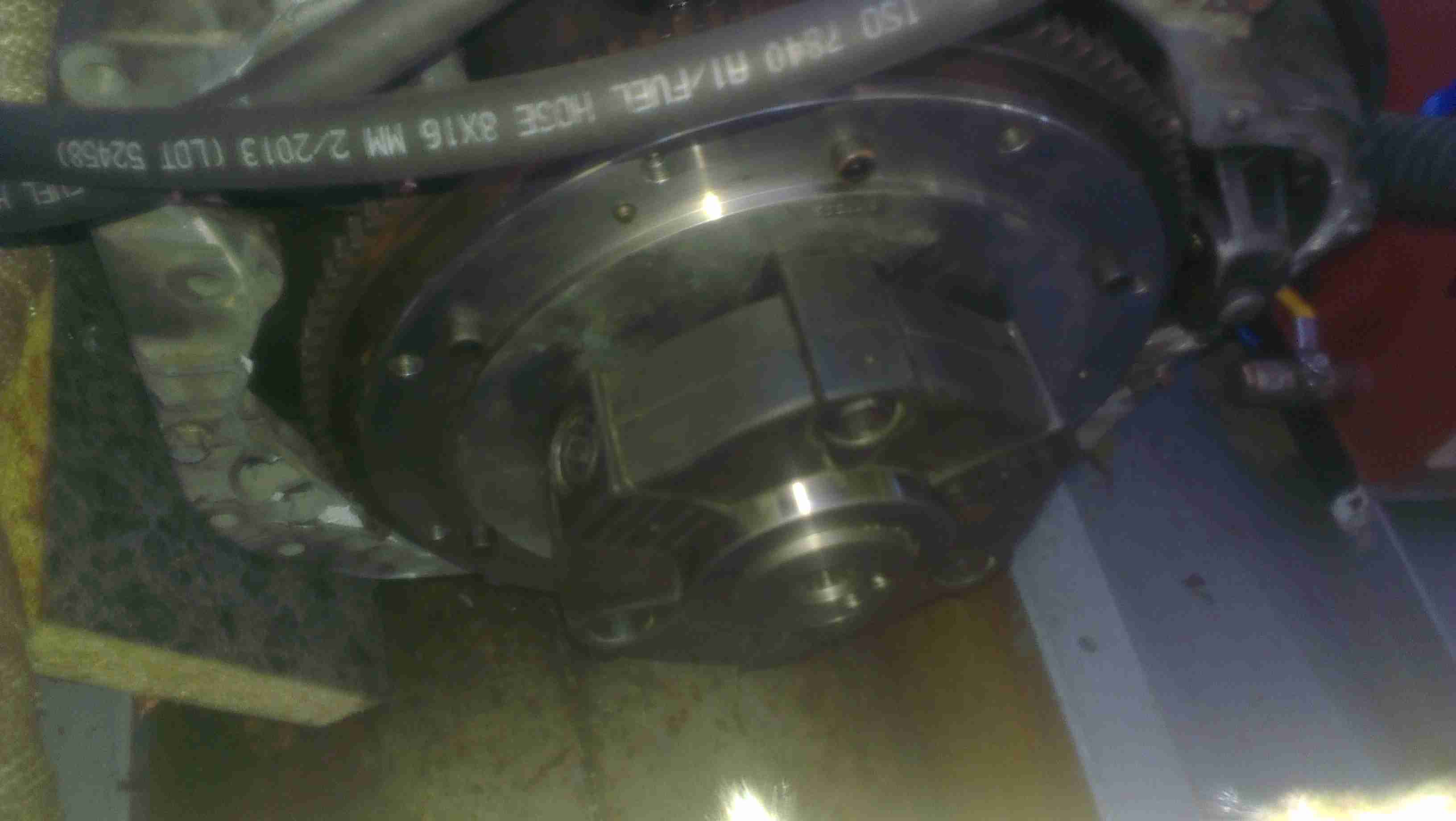
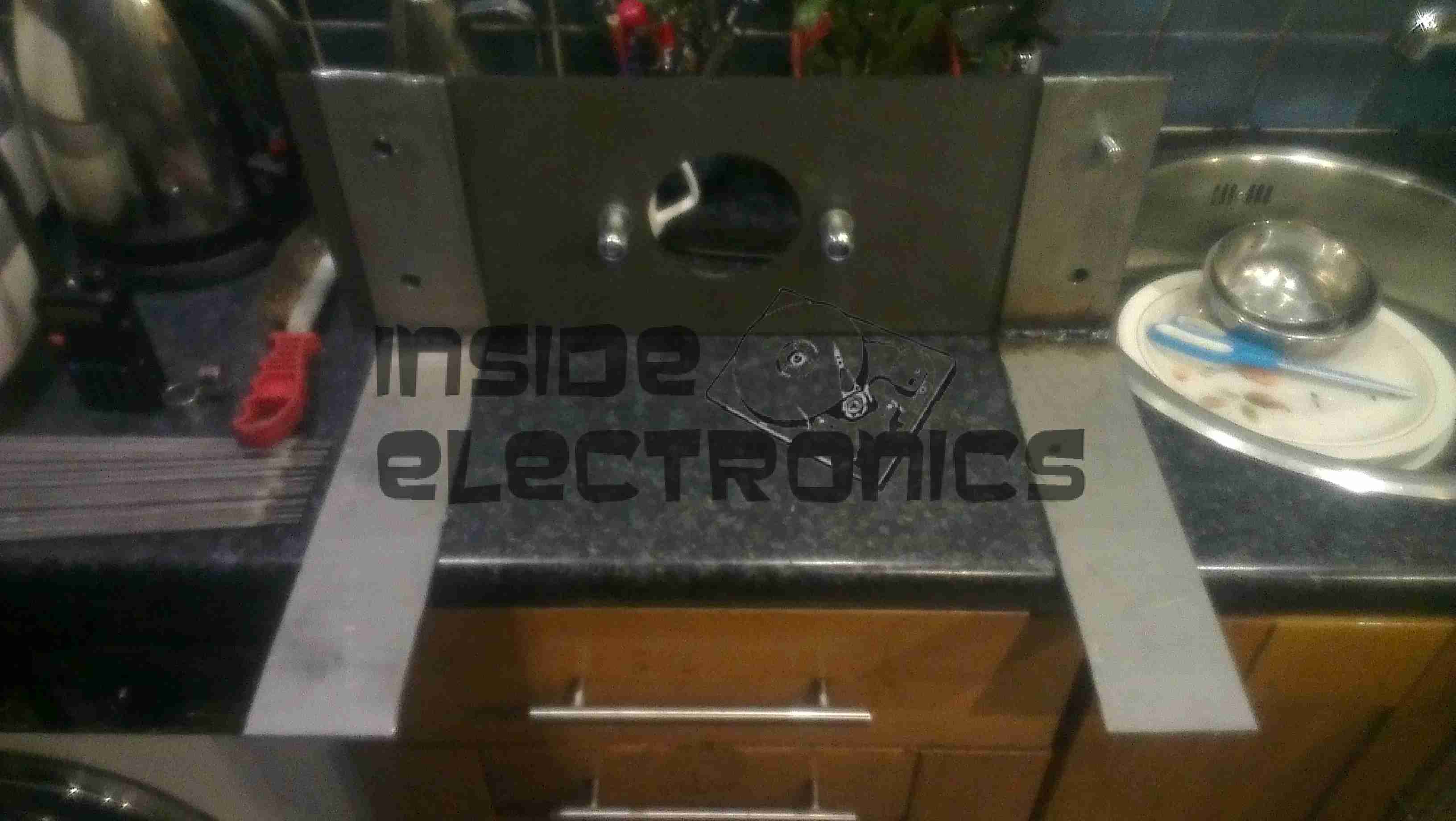
In the process of going through the boat mechanically, ready for this year’s cruising season, some damage was discovered on the face of the main hydraulic propulsion pump that drives the propeller.
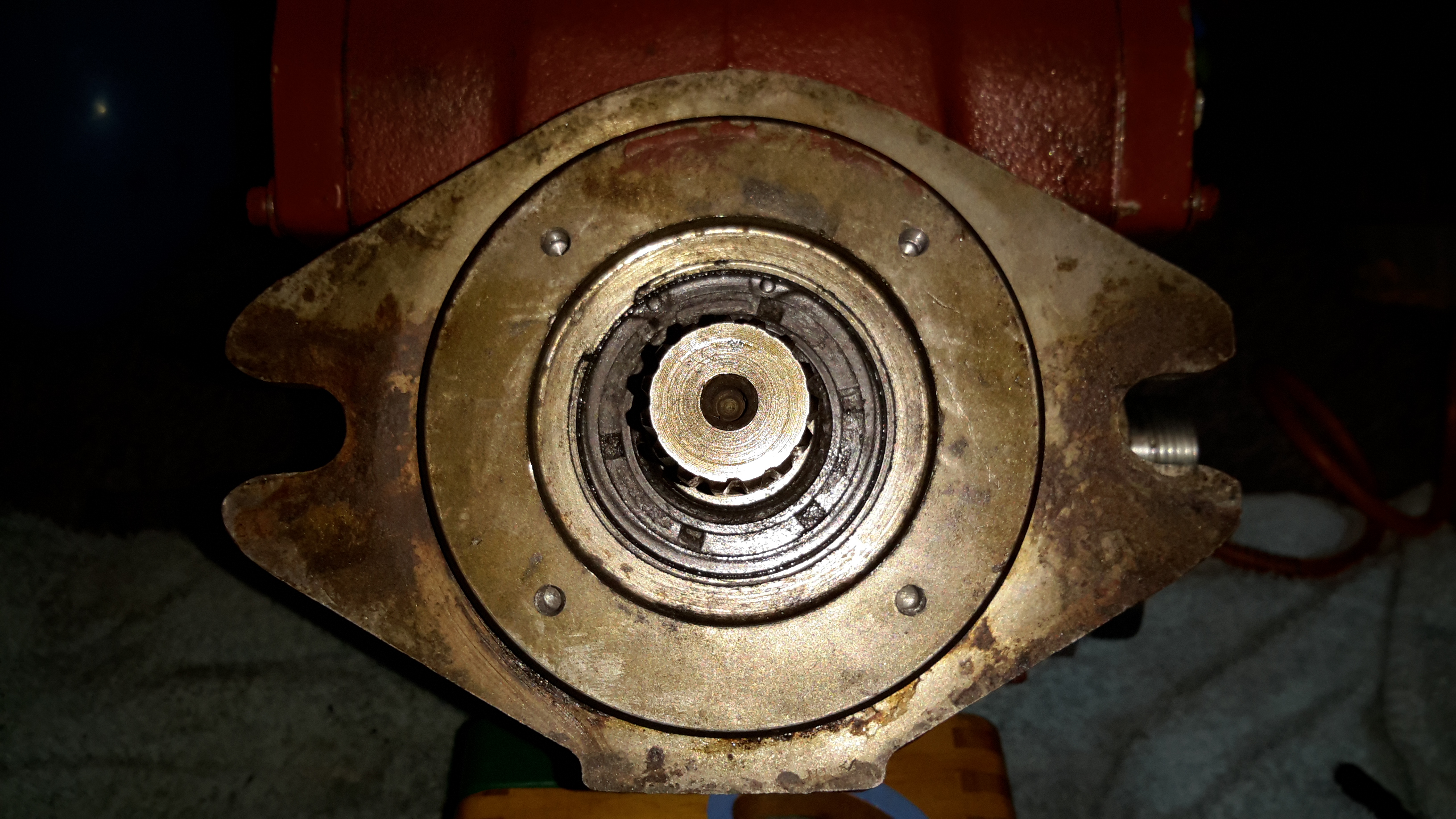
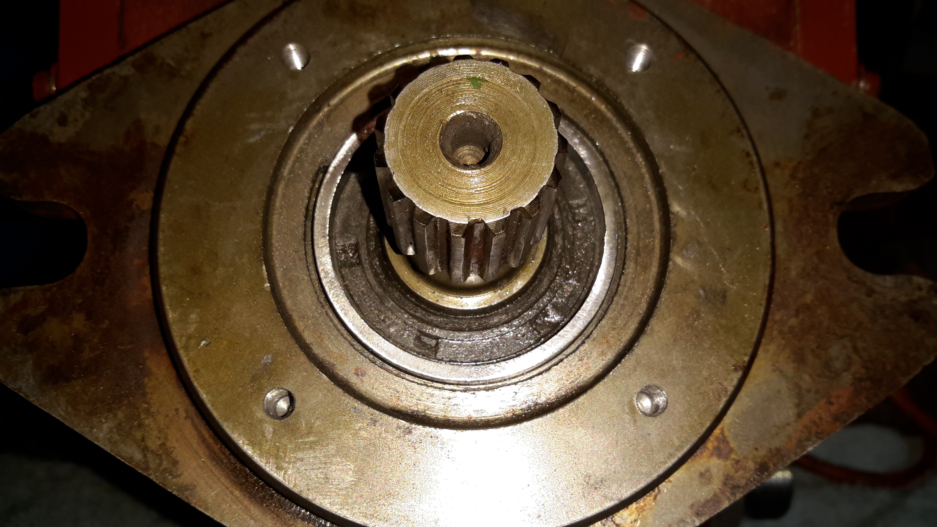
Face Damage
Here’s the front face of the pump, with it’s drive shaft. The circular ridge isn’t supposed to be there, it’s meant to be completely flat.
The central hub of the Centaflex coupling managed to loosen itself on the shaft (they’re pretty badly designed), and when the steel hub moved backward, it ground a very nice recess into the cast iron pump housing.
This managed to get deep enough where it compromised the circlip groove that holds both the oil seal & the mainshaft thrust bearing in place.
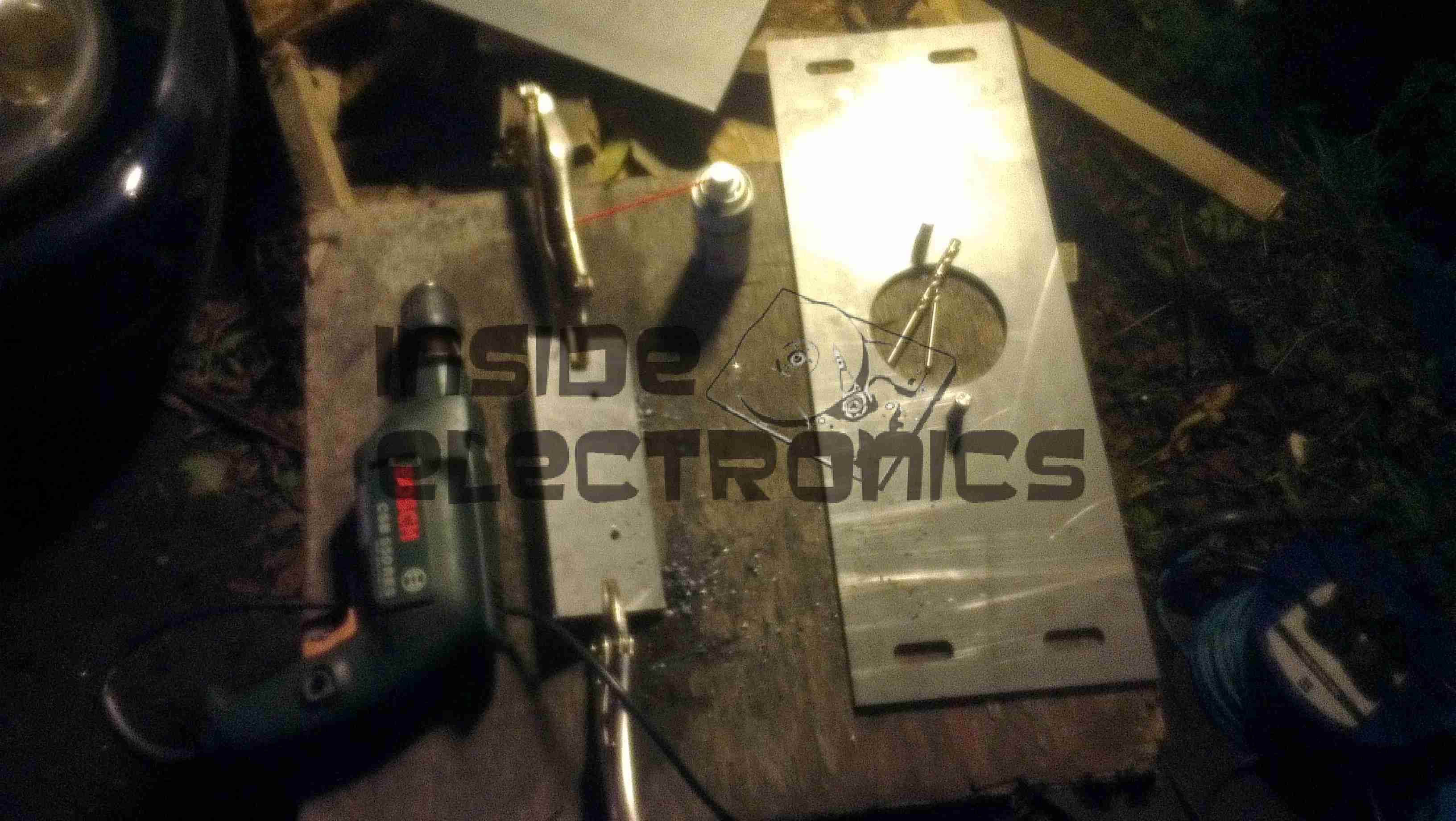
Spacer Ring
To save a considerable amount of cash (replacing the entire base casting of the pump would be hideously expensive), a 6mm ring was machined from steel, to hold the seal in place.
The face of the pump was then drilled & tapped for M5 screws.
Plate Fitted
Above, the repair plate has been fitted, with the spacer ring sandwiched between it & the oil seal, securing everything in place.
Having a replaceable wear plate screwed to the front of the pump also allows for easy future repair if the coupling moves again.
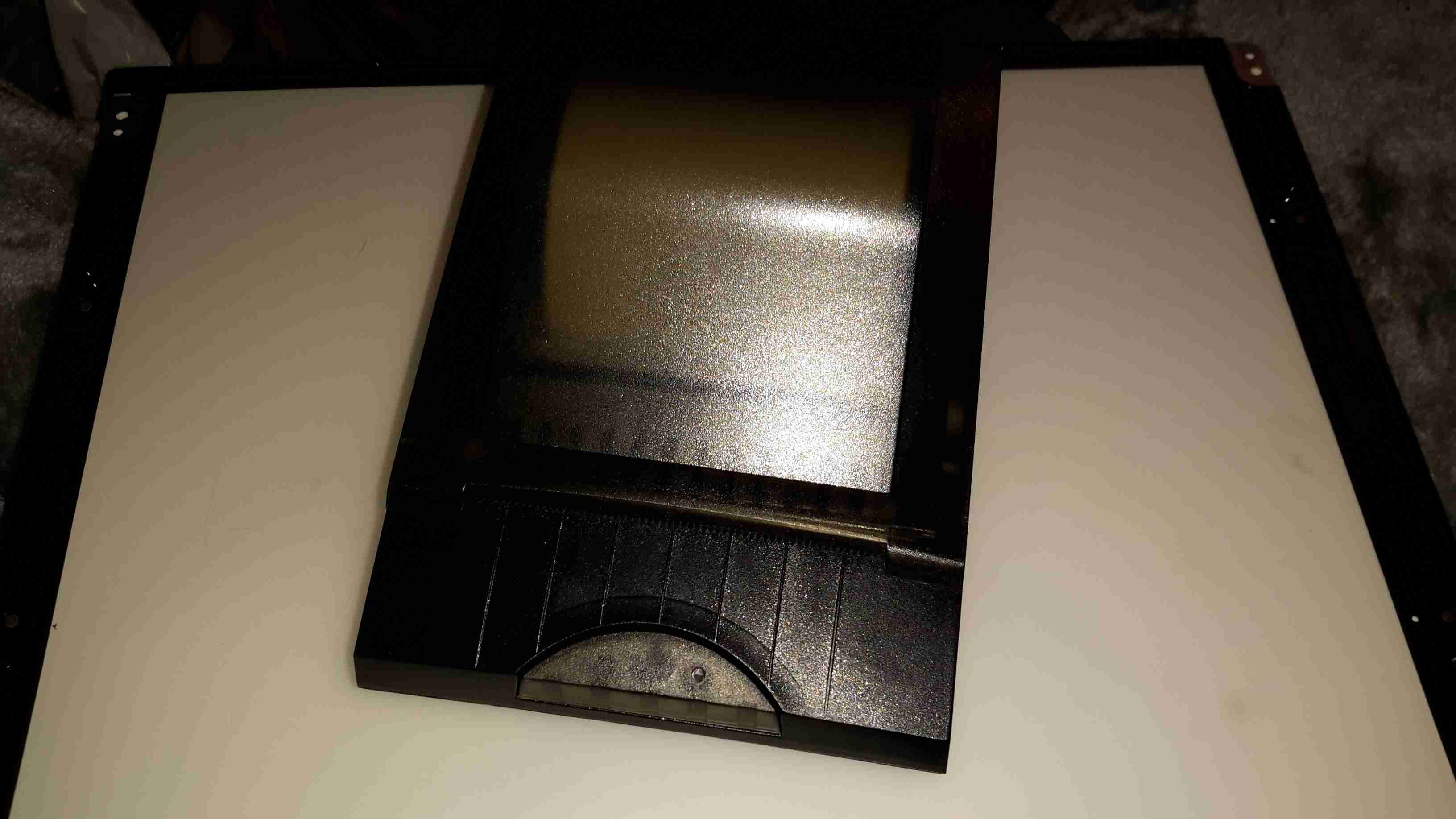
I have yet another receipt printer, this one appears to be brand new. It’s possibly the smallest thermal 80mm printer I have at the moment, and has both USB & Serial interfaces.
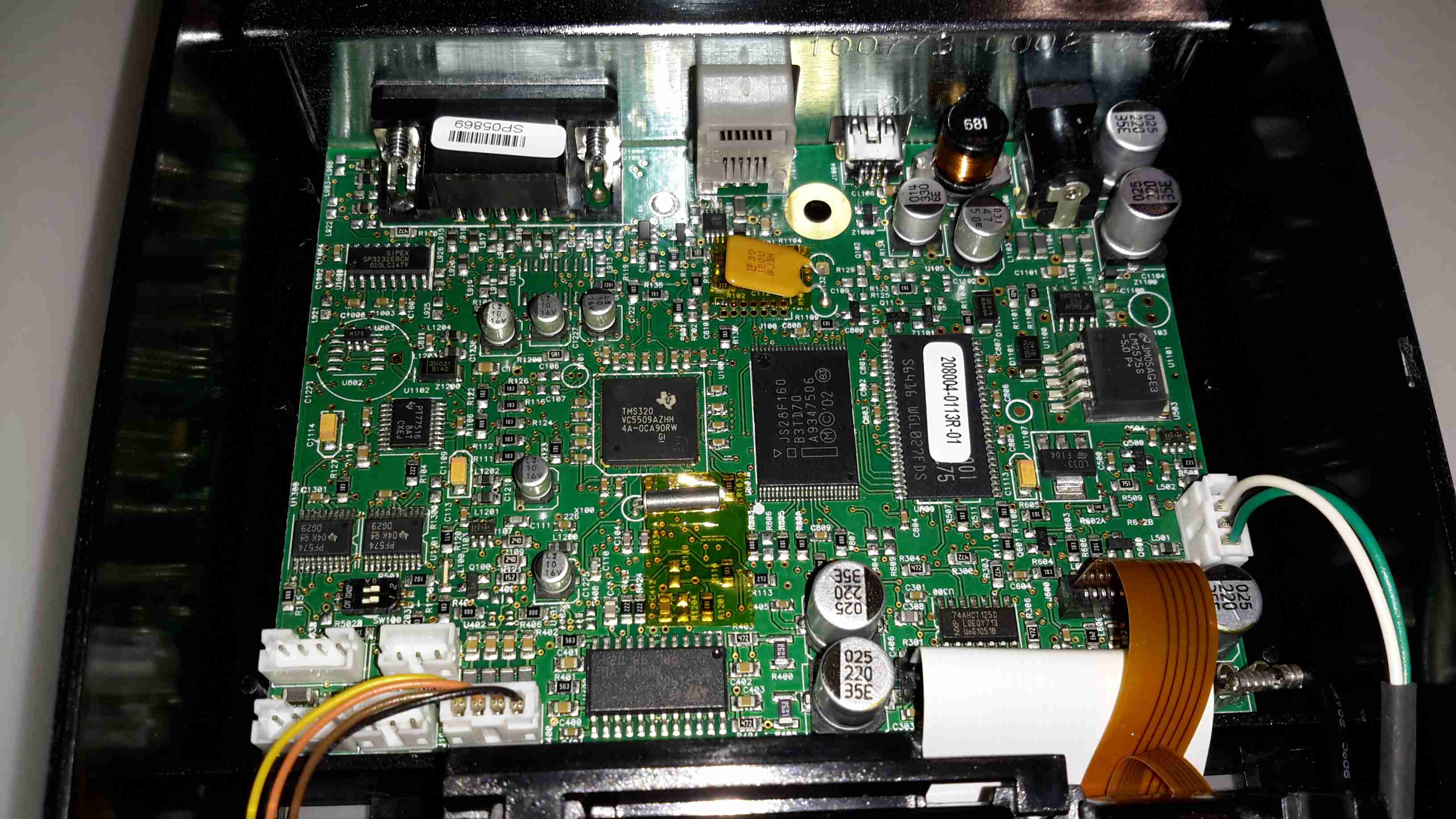
Controller PCB
There’s not much to these printers at all. Removing a single screw allows the case halves to separate, showing the guts. The controller is based around a Texas Instruments TMS320VC5509AFixed-Point DSP. It’s associated Flash ROM & RAM are to the right.
Power supply is dealt with in the top right of the PCB, with the interface ports further left.
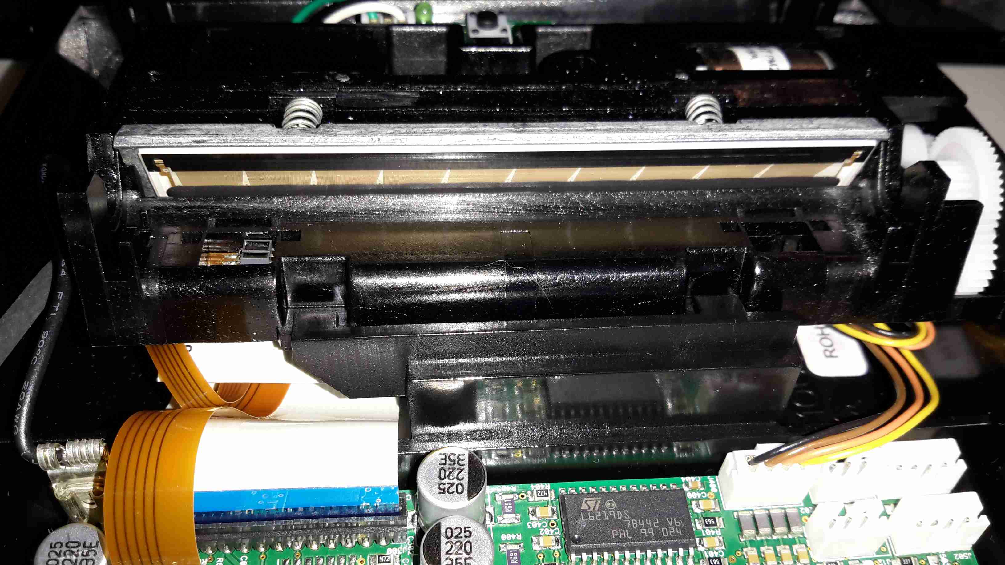
Print Head
Here’s the thermal mechanism itself, with the large print head. The stepper motor to drive the paper through the printer is just peeking out at top right. The paper present sensor is just under the left hand side of the print head.
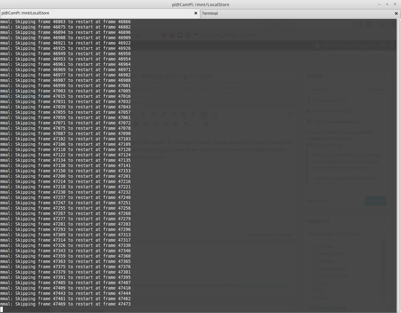
Sometimes while taking timelapse video on the Pi, it misses frames, for no apparent reason. I have been playing with various combinations of disks/SATA cases to see what the bottleneck is. Oddly enough a faster drive actually made the problem worse!
Really Bad Frame Skipping
Here’s an example of some really bad frame skipping, this is with a frame interval of 1250ms, which has worked fine in the past. The disk used is a 750GB WD Black 7200RPM, so disk access time shouldn’t be an issue.
Since frame skipping is rarely a problem in timelapse video I do, I’ve been searching for something to automatically renumber all the frames for processing into video – after writing my own script, which was a bit crusty, I came across a very handy script on SourceForge. It required a couple of small modifications to work correctly with what I want, but here’s the slightly modified version.
[snippet id=”1770″]
With the small modifications, it renumbers the images correctly for processing by AVConv.
More scripting to come when I sort out an automatic transcode kludge!
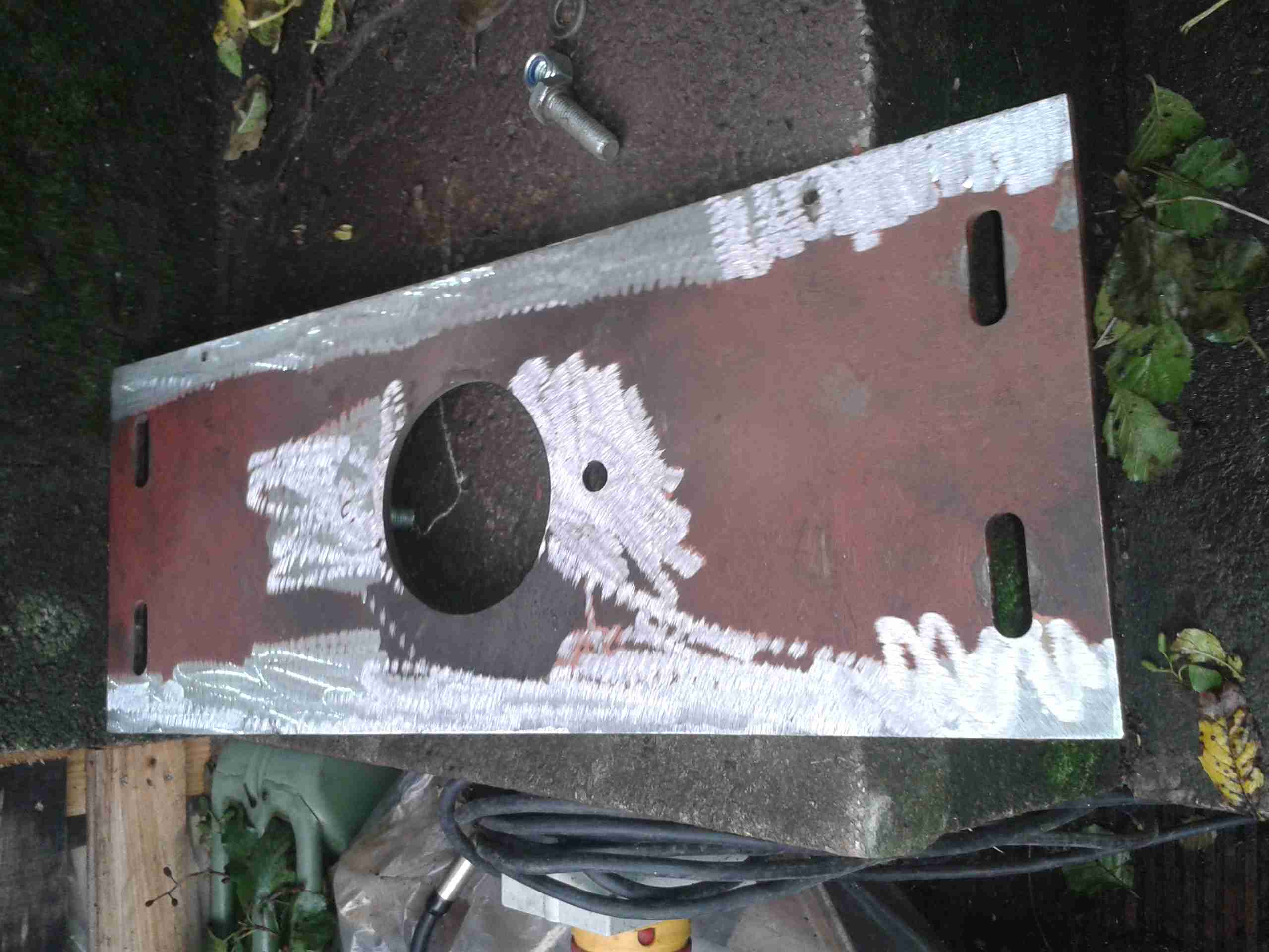
It’s time for the final part of getting the boat’s engine & drive back together, now I have the new coupling hub. I decided to address one of the issues with the pump mounting while I had everything in bits. When the hydraulic drive was installed, a custom plate was laser cut to fit the pump stack to, as we had no bellhousing with a standard mounting pattern.
Even though this plate is 10mm steel, under full load it actually bends – so to strengthen it along the long edge, I have welded a pair of ribs to the plate.
Pump Mounting Plate
The mounting plate as removed from the mounting brackets. The slotted holes at the sides allow for some movement to adjust the position of the pump & flywheel coupling.
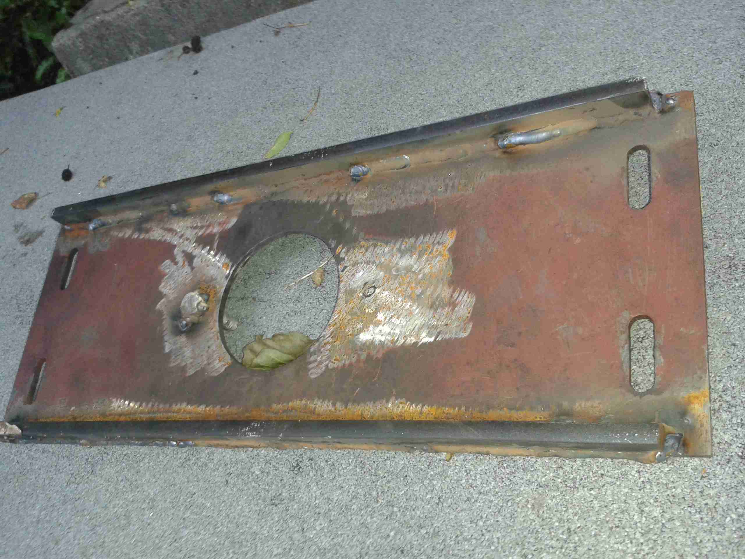
Prepared For Welding
I ground off the paint & grease with an abrasive disc, and am replacing one of the pump mounting studs while I’m at it.
Strengthening Ribs
Here’s the plate after welding. a pair of 10mm bars have been attached along the edges, this will give the mounting significantly more strength on the long axis & prevent any deformation.
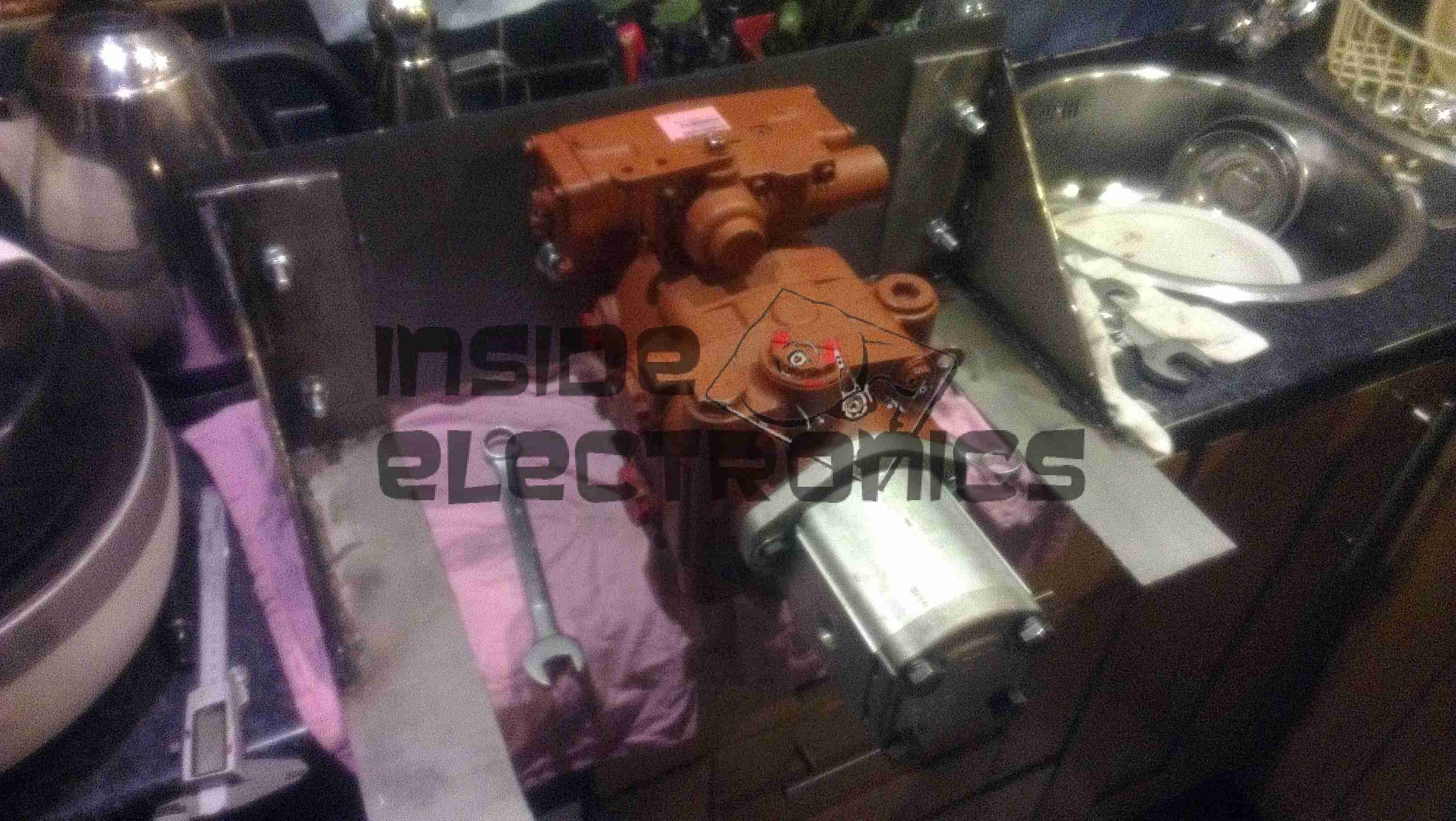
Pump On Hoist
Here the plate has been loosely mounted on it’s brackets, & I’ve got the pump stack with it’s associated tangle of hoses on the chain hoist. This unit is very heavy on it’s own – a 2 man job to lift it into place on it’s mounts – with the very stiff hydraulic hoses attached & filled with oil it’s absolutely unmanageable.
Lining Up The Mountings
Here the pump is being jostled into place. The central hole in the mounting plate is a very snug fit, if the pump doesn’t go in exactly straight it will jam & cause damage to both parts. The mating hole in the coupling hub can be seen here – it’s not quite lined up yet.
Almost There
We’ve got about 10mm to go before the pump is seated. It’s held in place with a pair of large studs & nuts.
Coupling Connected
Here the pump is fitted enough to get the main mounting bolts into the coupling. These are torqued down to 150ft/lbs – a difficult thing to do considering the restricted space in the engine bay.
Flush Mounting
The pump has been pulled down onto the plate evenly with the mounting studs, and is now completely flush with the plate. As can be seen, I didn’t bother tidying up the welds with a grinder, they aren’t in any visible place in normal operation, so it didn’t warrant the effort.
Pump Refitted
Finally, the control cable is reattached to the pump’s control lever & everything is installed! A short test trip proved that everything was stable & no undue movement of the pump or coupling was noticed.
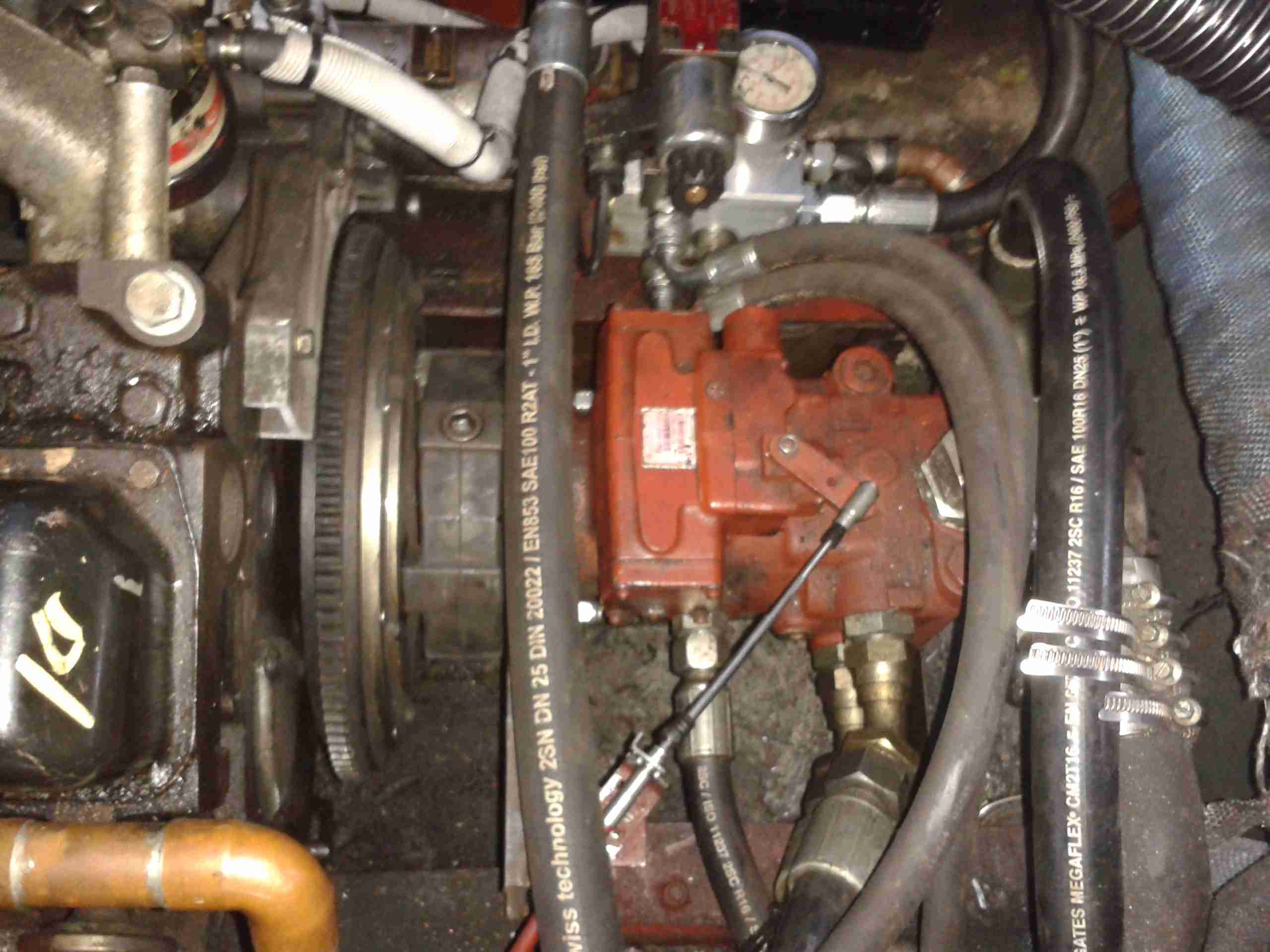
As I have posted about before, the main propulsion system onboard the boat is all hydraulic. To get the drive from the flywheel of the engine to the hydraulic pump stack, a custom drive plate was machined by Centa Transmissions over in Yorkshire, and a Centaflex A coupling was fitted to this.
Centaflex A Coupling
This coupling is a big rubber doughnut, bolted to a centre hub of steel. The steel hub is splined onto the input shaft of the hydraulic pump stack.
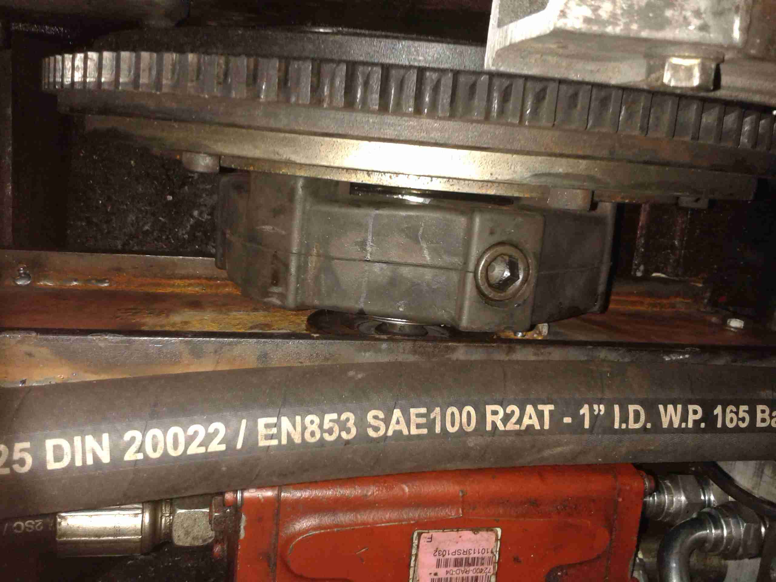
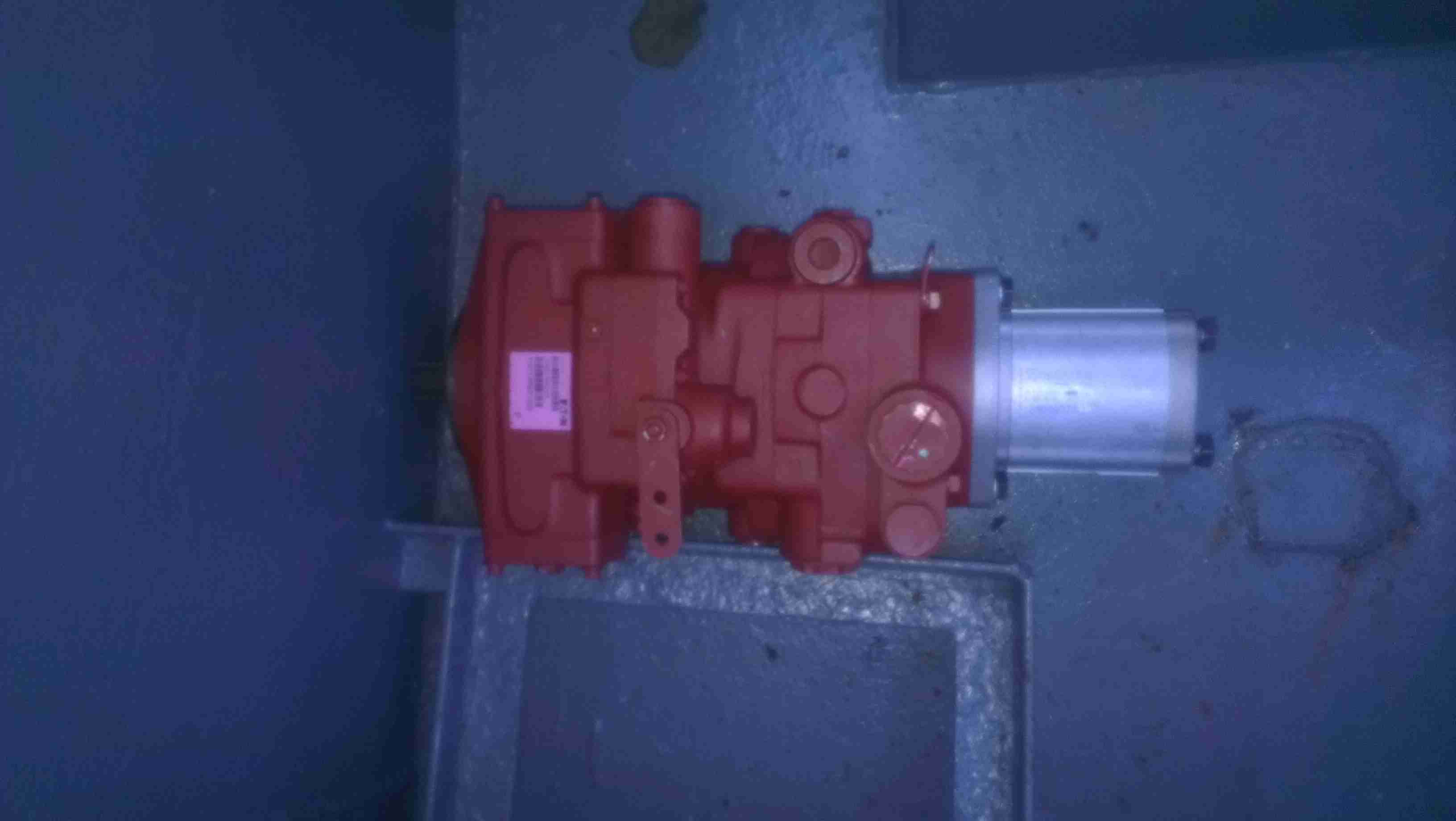
Pump Stack
The problem we’ve had is that to prevent the coupling from riding along the splines in operation, a pair of giant grub screws are provided in the side of the centre steel boss, that compress the splines to lock the device in place. These screws are a nightmare to get tightened down (the engineer from Centa who originally came to survey the system said we’d probably shear some tools off trying).
Because of this, the grub screws have loosened over the last 350-odd hours of running & this has had the effect of totally destroying the splines in the hub.
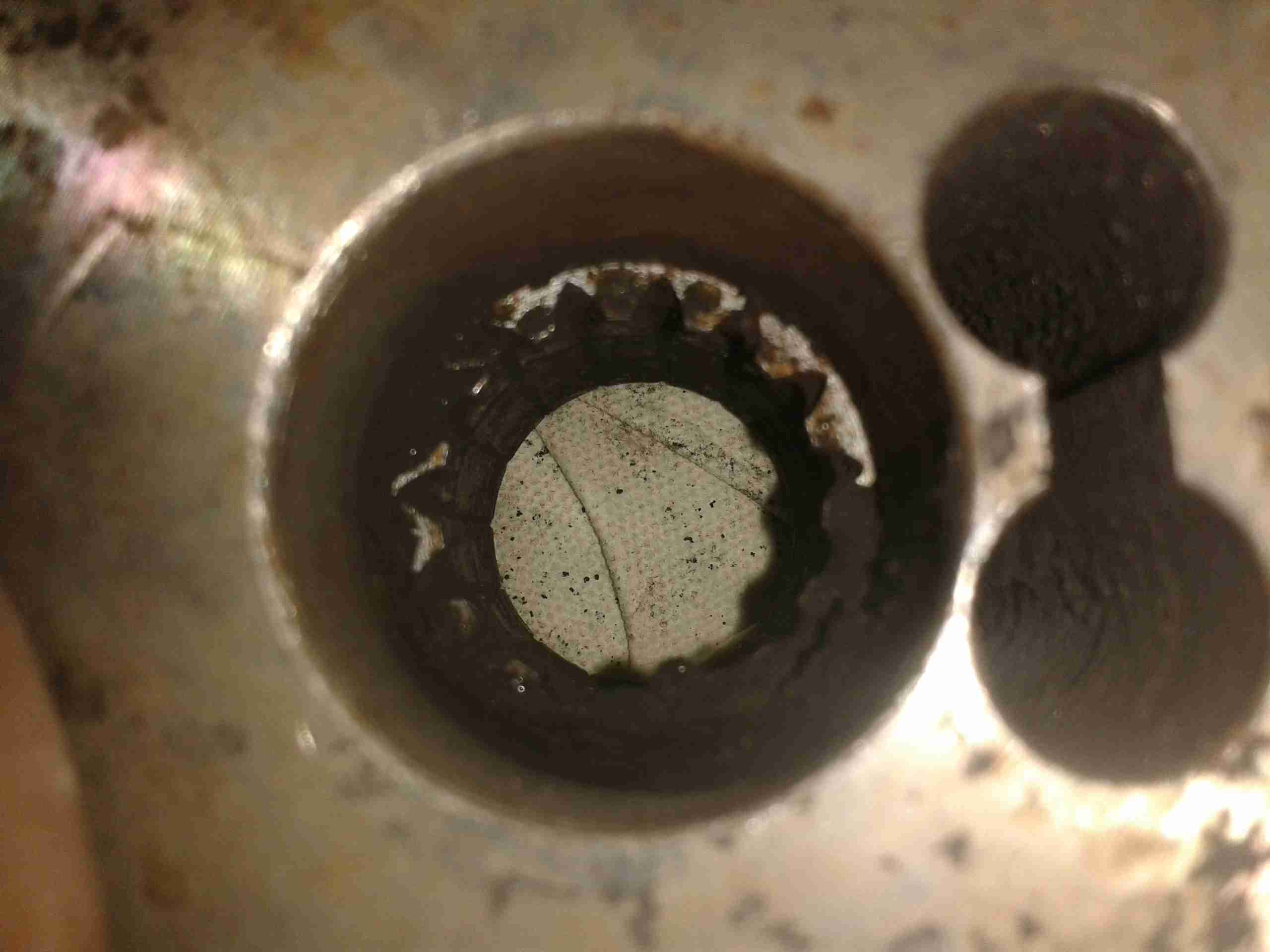
Spline Remains
Here’s the backside of the centre boss, with what remains of the splines, the figure-8 shaped gap on the right is where the securing grub screws deform the steel to lock the coupling into place.
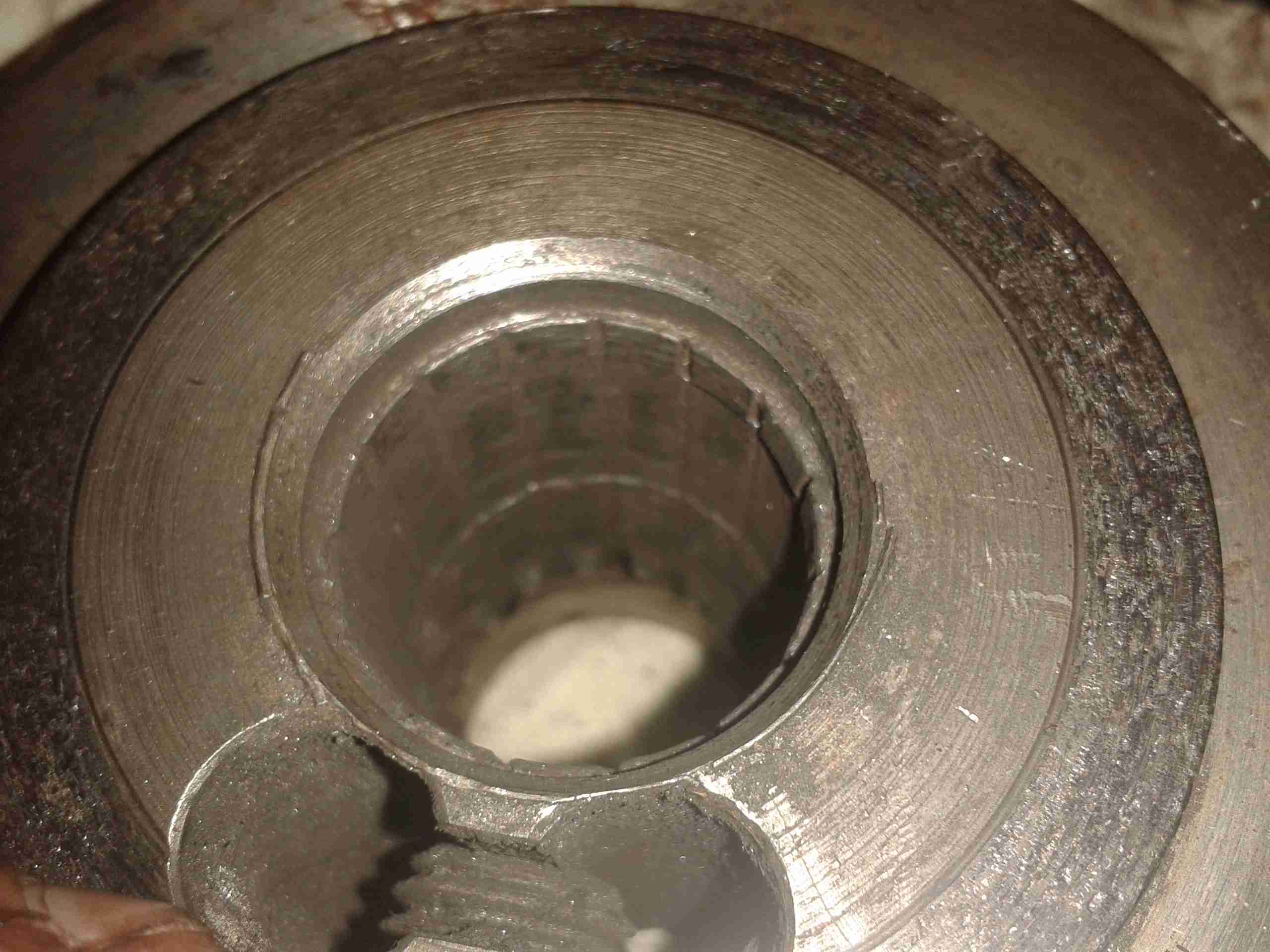
No More Splines
Here’s the other side of the coupling, showing the damage. The splines have effectively been totally removed, as if I’d gone in there with a boring bar on the lathe. Luckily this part isn’t too expensive to replace, and no damage was done to the input shaft of the hydraulic pump stack (Mega ££££). Quite luckily, this damage got to the point of failure while running the engine on the mooring, so it didn’t leave us stranded somewhere without motive power.
Since everything in my shack is run from 12v, I thought it would be handy to convert my new scope to 12v as well, as 99% of the places I find myself needing test gear are off grid, with no access to mains supplies.
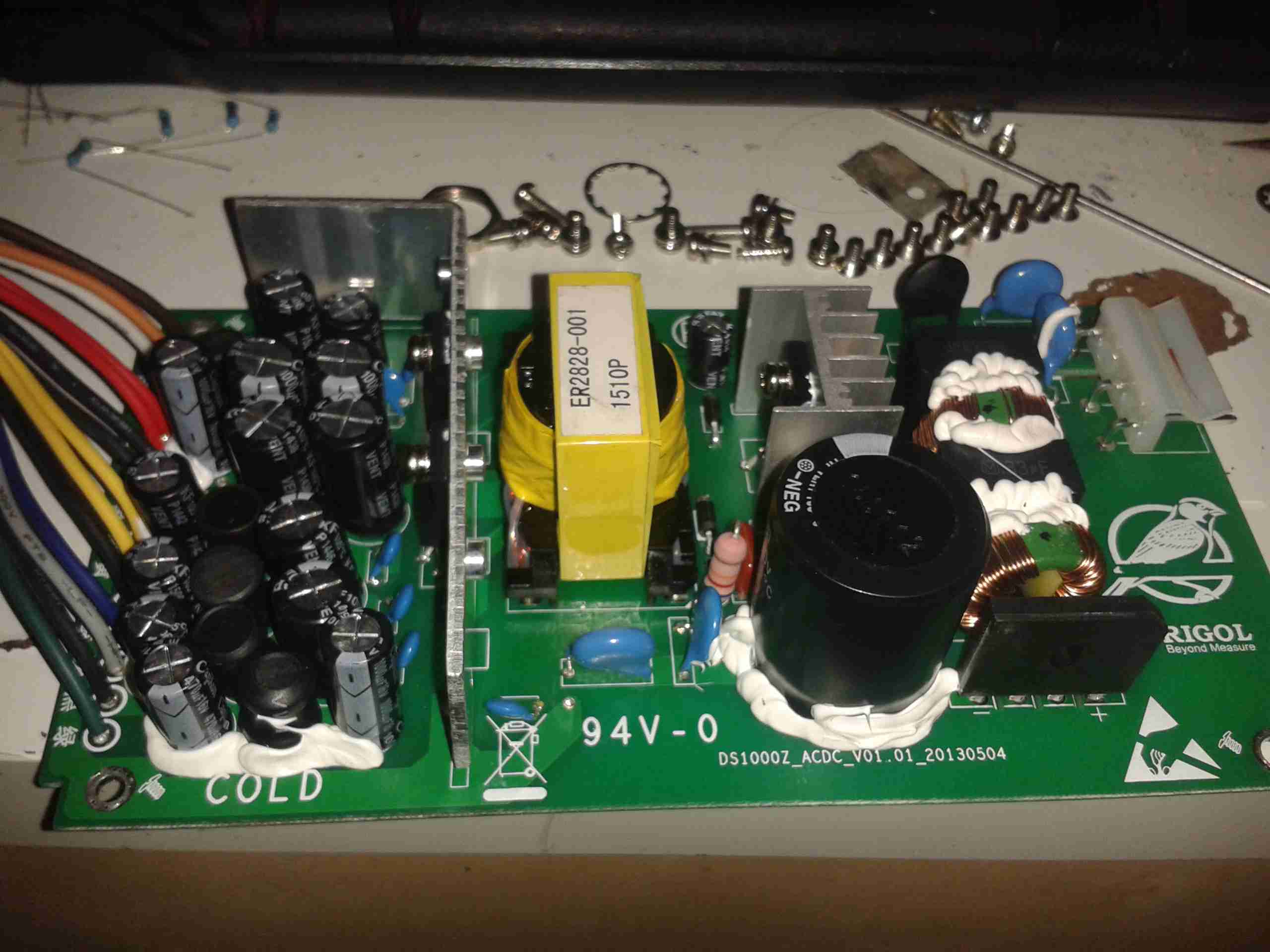
Mains PSU
Here’s the factory mains SMPS unit from the back of the scope. This is a nice multi-rail unit, with several different outputs, the table below details the wiring of the PSU.
Connector Pin
PCB Pin
Signal
Measured Voltage
Mainboard
Rectifier Rating
Wire Colour
5
1
AC_TRIG
N/A
AC_TRIG
N/A
BROWN
2
2
+9v_GND
N/A
FAN --
NA
ORANGE
11
3
+9V
10.16V
FAN +
2A
WHITE
6
4
+5V
5.1V
5V5A
20A
RED
13
5
+5V
5.1V
5V5A
20A
RED
7
6
GND
N/A
GND
N/A
BLACK
8
7
GND
N/A
GND
N/A
BLACK
3
8
+7.5V
6.9V
6.3V
20A
YELLOW
10
9
+7.5V
6.9V
6.3V
20A
YELLOW
1
10
GND
N/A
GND
N/A
BLACK
12
11
17.5V
17.51V
17.5V
2A
BLUE
9
12
-17.5V
-17.36V
-17.5V
2A
GREY
14
13
GND
N/A
GND
N/A
BLACK
4
14
-7.5V
-6.84V
-7.5V
2A
GREEN
The only feature I will lose if I make this switch is AC line triggering, but I never use that anyway, so it’s not a big issue for me.
Since I have been able to locate the connector, the plan is to design a replacement low voltage supply unit for the scope, with the same footprint as the original AC mains supply. This will allow me to do a direct swap without causing any damage or modifying the original supply.
This method will allow me to swap the 240v supply back into the scope if I ever come to need it.
I’m planning to use the LTC3863 DC-DC Controller from Linear Tech to generate the negative rails, this will go down to -150v on the output, so it’s pretty much perfect to generate them.
PSU Output Side
Here’s the output side of the mains PSU, it has a lot of filtering on the output rails, the two TO220 devices are the output rectifiers for the +5v & +7.5v rails, these are rated at 20A, 60V.
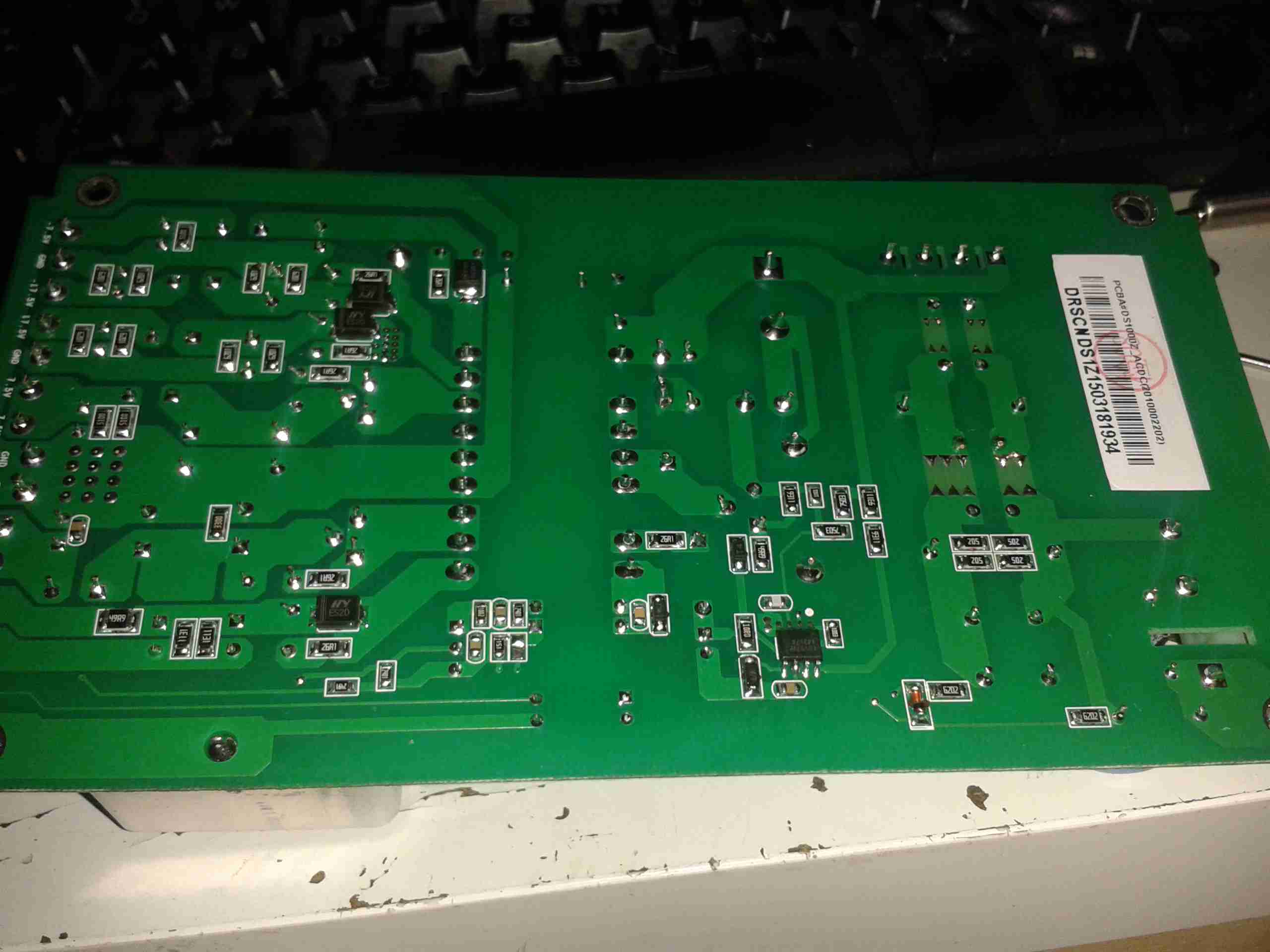
PCB Bottom
Here’s the bottom side of the PCB. It’s a really nicely designed PSU, massive isolation gap, spark gaps on the primary side & good filtering. The output side on the left has the rectifier diodes for the other voltage rails, these are only 2A rated, so designing the inverting supply to generate the negative rails will be pretty easy.
From looking at the PCB markings on both the mainboard & the PSU, the +9v rail seems to be used to drive the fan, both silkscreen markings indicate this.
The voltages marked on the PSU & the mainboard connector don’t quite match up though, there’s a small variation in the stated voltage between the two. This is most likely because all of the regulation of the supplies seems to be done on the mainboard, there are several linear regulators, and a few DC-DC switchers. Providing that the replacement supply isn’t noisy it should work fine.
This is backed up by the fact that the mains PSU only seems to regulate the +5v rail – on measuring the rails that’s the only one that’s close to spec.
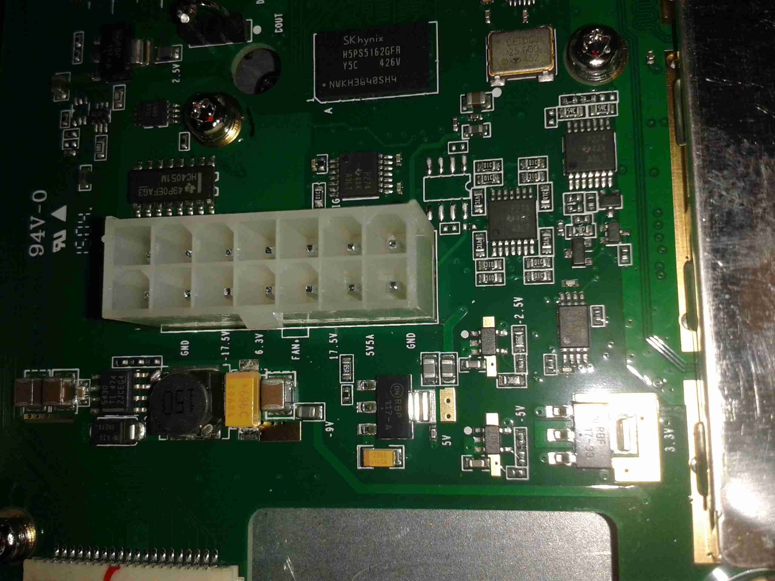
Mainboard Power
Here’s the mainboard power connector, with it’s silkscreen labelling on the pins. (Very useful). As can be seen here, there’s at least 5 regulators, of both switching & linear types here, generating both positive & negative rails.
I recently dug out my other card printer to fit it with a 12v regulator, (it’s 24v at the moment), and figured I’d do a teardown post while I had the thing in bits.
This is a less industrial unit than my Zebra P330i, but unlike the Zebra, it has automatic duplexing, it doesn’t have Ethernet connectivity though.
Unlike domestic printers, which are built down to a price, these machines are very much built up to a spec, and feature some very high quality components.
Naked Printer
Here’s the mechanism with the cowling removed. This is the main drive side of the printer, with the main drive stepper at left, ribbon take-up spool motor lower right, and the duplex module stepper motors at far right.
Main Motor Drive
The main drive motor runs the various rollers in the card path through a pair of synchronous belts, shown here.
Main Stepper
The stepper itself is a quality ball-bearing Sanyo Denki bipolar motor.
Main Stepper Driver
Electrical drive is provided to the stepper with a L6258EX DMOS universal motor driver. This chip can also drive DC motors as well as steppers.
Ribbon Supply Spool
Here is the encoder geared onto the ribbon supply spool. This is used to monitor the speed the ribbon is moving relative to the card.
Printer Top
Here’s a top view through the printer, the blue roller on the left cleans the card as it’s pulled from the feeder, the gold coloured spool to it’s right is the ribbon supply reel. The cooling fan on the right serves to stop the print head overheating during heavy use.
Spool Take Up Motor
The spool take-up reel is powered by another very high quality motor, a Buhler DC gearmotor. These printers are very heavily over engineered!
This motor drives the spool through an O-Ring belt, before the gear above. This allows the drive to slip in the event the ribbon jams, preventing it from breaking.
Duplex Unit Stepper Drivers
The pair of steppers that operate the duplexing unit are driven by a separate board, with a pair of L6219DS bipolar stepper driver ICs. There are also a couple of opto-sensors on this board for the output hopper.
Main Control PCB
All the mechanisms of the printer are controlled from this main PCB, which handles all logic & power supply functions. Sections on the board are unpopulated, these would be for the Ethernet interface, smart card programming & magstripe programming.
Main CPU
The brains of the operation is this ColdFire MCF5208CVM166 32-bit microprocessor. It features 16KB of RAM, 8KB of cache, DMA controller, 3 UARTs, SPI, 10/100M Ethernet and low power management. This is a fairly powerful processor, running at 166MHz.
It’s paired with an external 128Mbit SDRAM from Samsung, and a Spansion 8Mbit boot sector flash, for firmware storage.
USB Interface & Power Input
Here the USB interface IC is located. It’s a USBN9604 from Texas Instruments, this interfaces with the main CPU via serial.
Following on from my review, here are some internal views & detail on the components used in this radio. Below is an overview of the main PCB with the top plate removed from the radio.
Cover RemovedRF Final Amplifier Stage
Most visible are these MOSFETs, which are Mitsubishi RD70HVF1 VHF/UHF power devices. Rated for a maximum of 75W output power at 12.5v (absolute maximum of 150W, these are used well within their power ratings. They are joined to the PCB with heavy soldering, with bypass caps tacked right on to the leads.
RF Pre Drivers
Here is the RF pre-driver stage, with intermediate transistors hidden under the small brass heatspreader.
Power Section
In the top left corner of the radio, near the power input leads, is the power supply & audio amplifier section. Clearly visible are the pair of LA4425A 5W audio power amplifier ICs, these drive the speakers on the top of the radio. Either side of these parts are a 7809 & a 7805 – both linear regulators providing +9v & +5v logic supplies respectively. The large TO220 package device is a KIA378R08PI 3A LDO regulator with ON/OFF control, this one outputs +8v. Just visible in the top right corner are the sockets for the speaker connections.
DTMF Circuits
Here are the two ICs for dealing with DTMF tones, they are HM9170 receivers.
Glue Logic
In the corner next to the interface jack, there are some CD4066B Quad Bilateral switches. These make sense since the interface jack has more than a single purpose, these will switch signals depending on what is connected.
RF Section
Here are visible the RF cans for the oscillators, the crystals visible next to the can at the top. The shields are soldered on, so no opening these unfortunately.
Also visible in this image is a CMX138A Audio Scrambler & Sub-Audio Signalling processor. This IC deals with the Voice Inversion Scrambling feature of the radio, & processes the incoming audio before being sent to the modulator.
Output Filter Network
Shown here is the RF output filter network, this radio uses relays for switching instead of PIN diodes, I imagine for cost reasons. The relay closest to the RF output socket has had a slight accident 🙂 This is slated to be replaced soon.
RF Output Jack
Finally, the RF output jack.
Audio Speakers
Here the speakers are shown, attached to the bottom of the top plate. They are both rated 8Ω 1W.
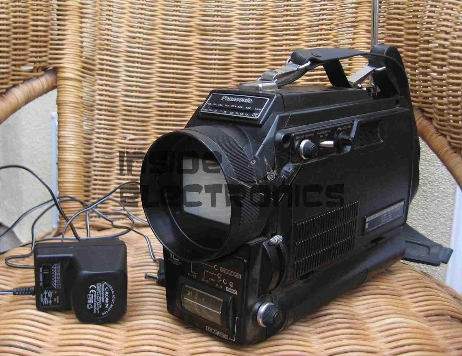
I recently managed to score a 3″ B&W portable TV on eBay, a Panasonic TR-3000G. As these old units are now useless, thanks to the switch off of analogue TV signalling, I figured I could find a composite signal internally & drive the CRT with an external source.
Panasonic TR-3000G
Here’s the TV in it’s native state. Running from 9v DC, or 6 D size cells. I’m guessing from somewhere around the 1970’s. Here is the CRT & associated drive circuitry, removed from the casing:
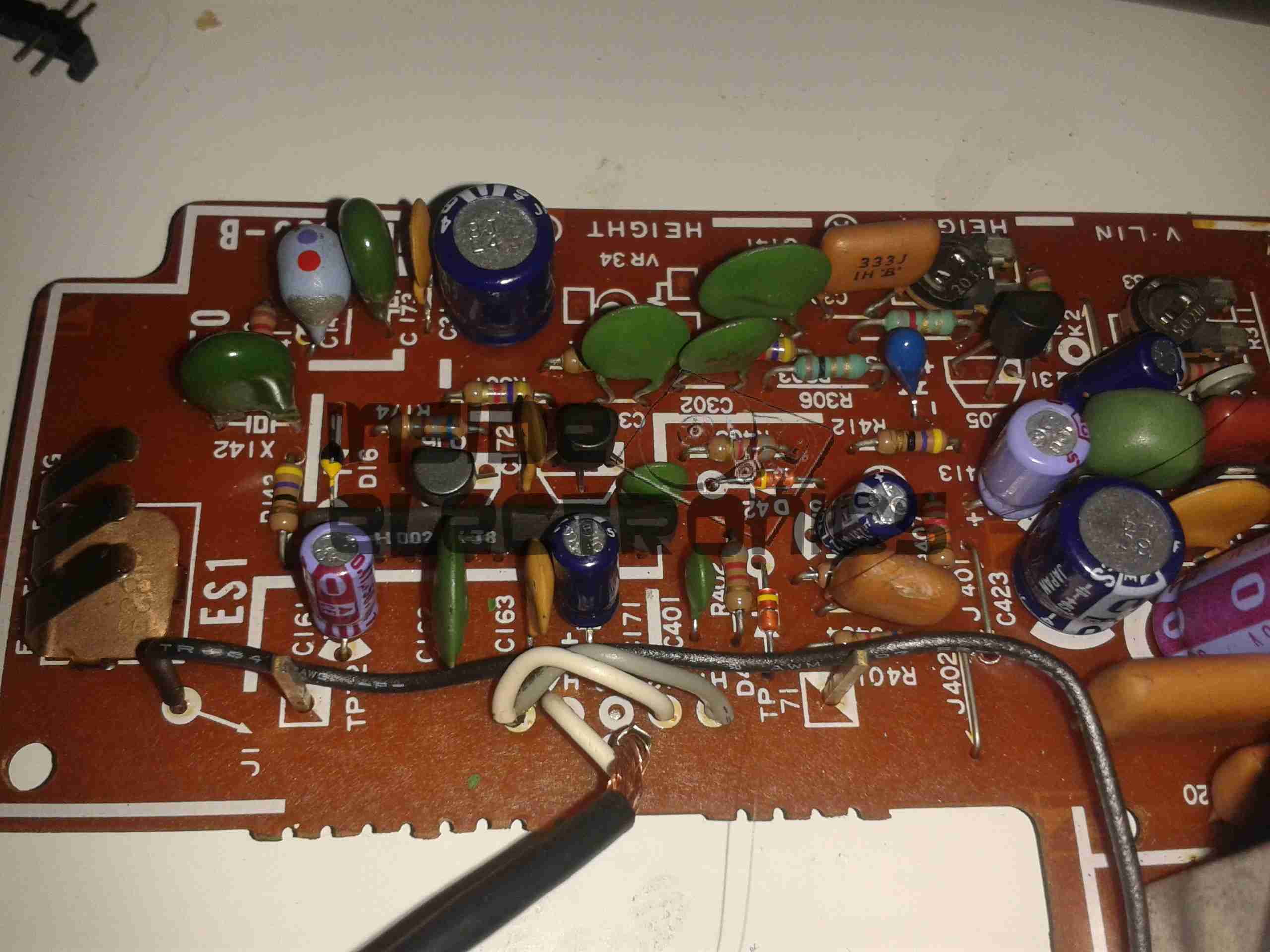
CRT Module
After dissecting the loom wiring between the CRT board & the RF/tuner board, I figured out I had to short out Pins 1,2 & 5 on the H header to get the CRT to operate straight from the power switch. This board also generates the required voltages & signals to drive the RF tuner section. I have removed the loom from this, as the PCB operates fine without. It doesn’t seem to be fussy about power input either: it’s specified at 9v, but seems to operate fine between 7.5v & 14.5v DC without issue.
Video Connections
Tracing the wiring from the tuner PCB revealed a length of coax snaking off to the section marked Video/Sync. I successfully found the composite input!
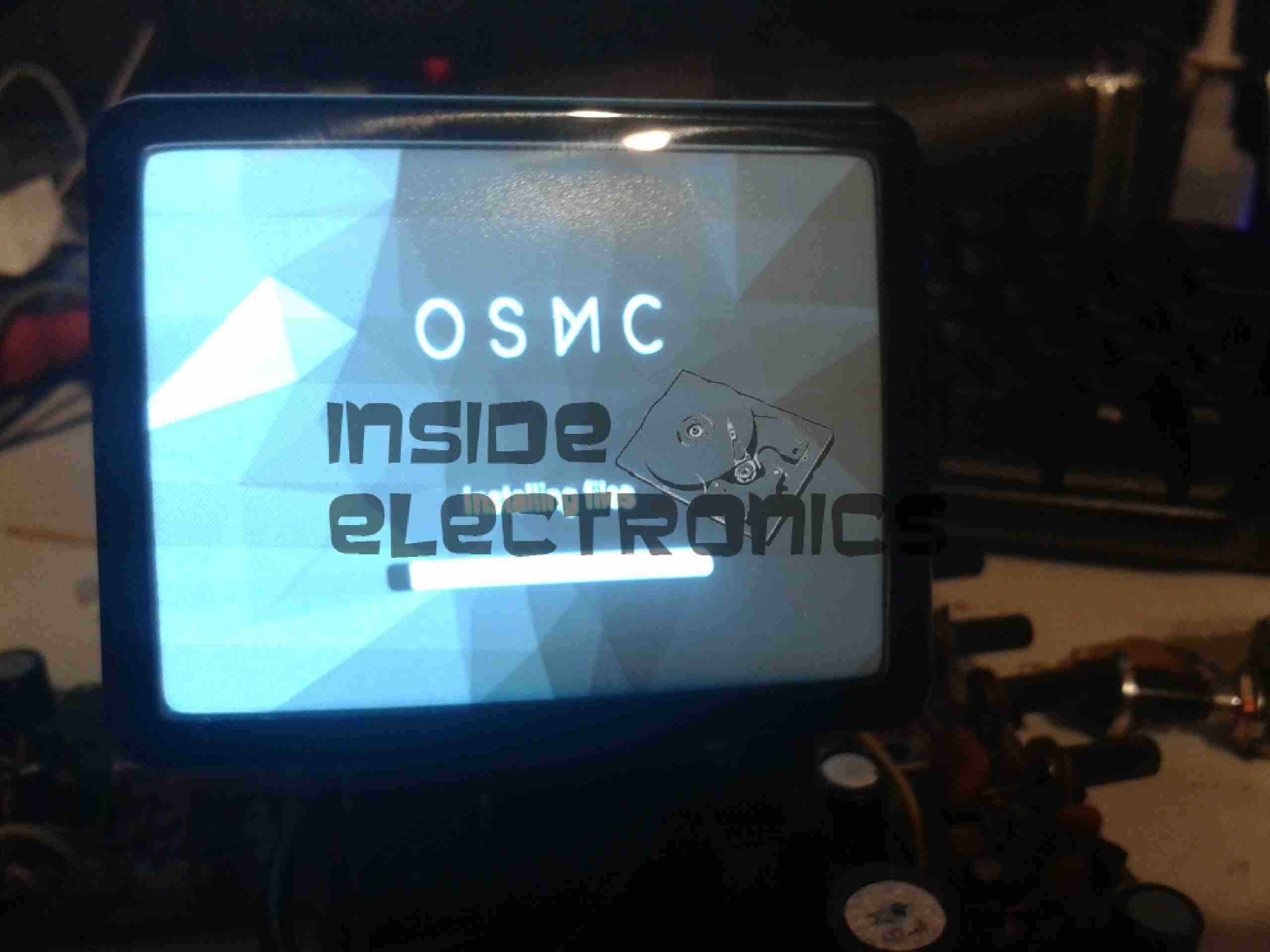
Running OSMC
A quick bit of wiring to a Raspberry Pi, & we have stable video! For such an old unit, the picture quality is brilliant, very sharp focus.
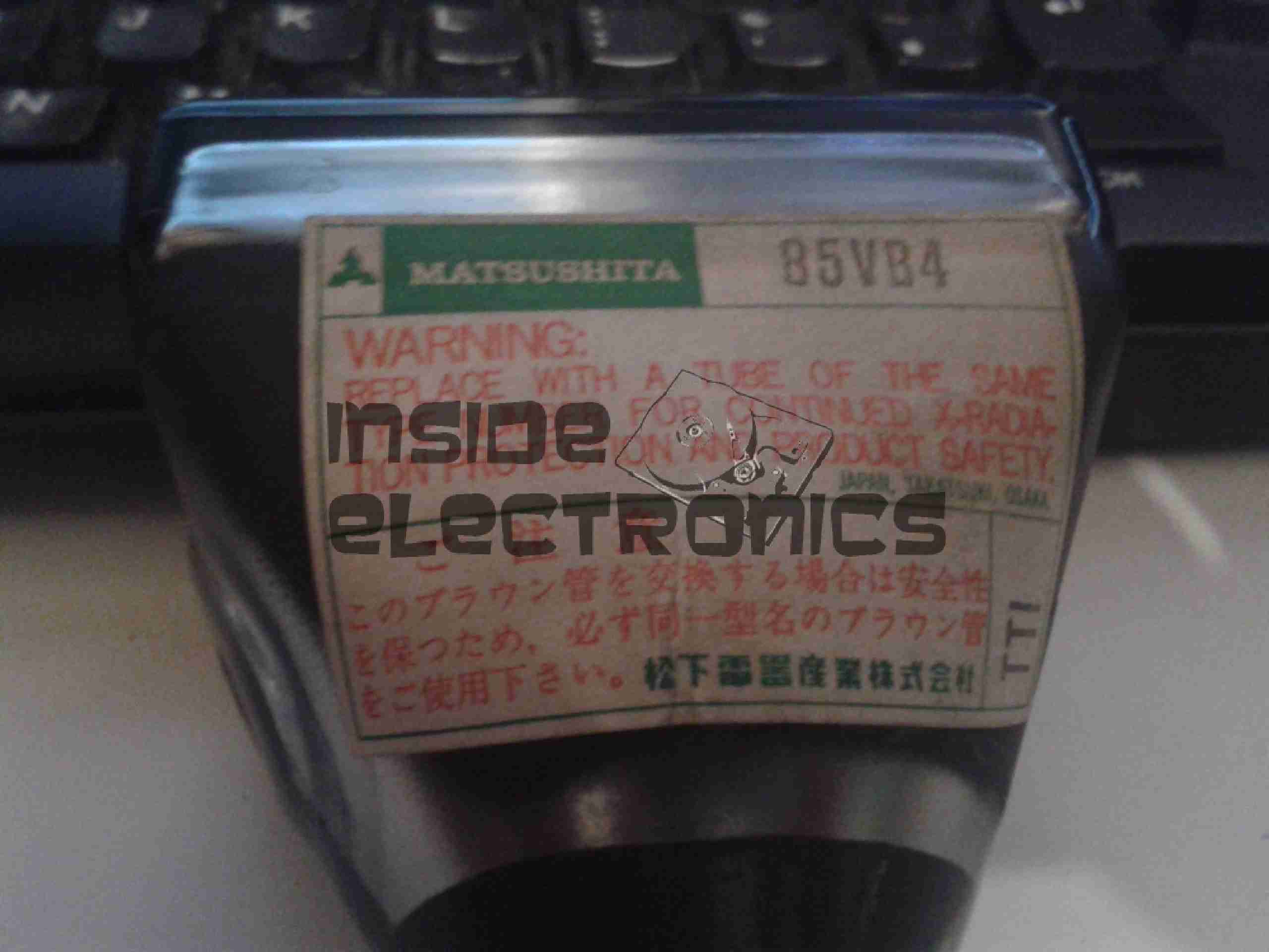
Matsushita 85VB4 CRT
Closeup of the CRT itself. I haven’t been able to find much data on this unit, but I’m guessing it’s similar to many commercial viewfinder CRTs.
Electron Gun Closeup
Amazingly, there isn’t a single IC in the video circuitry, it’s all discrete components. This probably accounts for the large overall size of the control PCB. Viewfinder CRTs from a few years later on are usually driven with a single IC & a few passives that provide all the same functions.
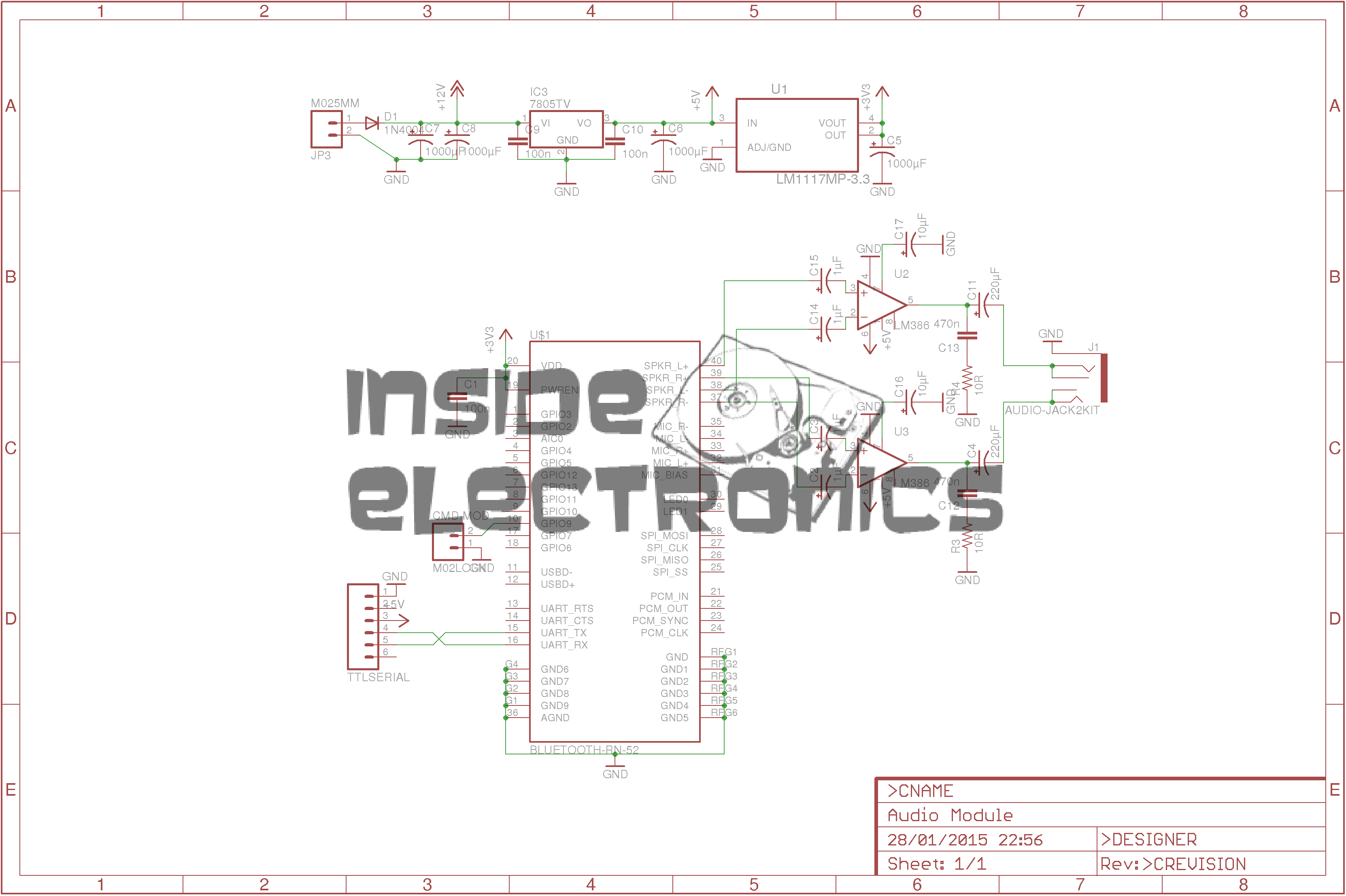
I’ve been doing some tinkering with the RN-52 Bluetooth Audio module from Roving Networks, in prep for building a portable wireless speaker system, & thought I’d share my designs.
Initially I was having some issues with RF noise on the audio output from the RN-52, as I was only using the outputs single-ended. The module didn’t like this treatment, with all the RF whine coming straight out of the speakers.
To fix this issue I have used a pair of jellybean LM386 audio power amplifiers, running in differential input mode. This solves the high-pitched whine when the audio is enabled, & also allows the module to directly drive a set of 32Ω headphones at a reasonable level.
In Eagle I have designed a simple board, routing only the audio output, serial TTL & command mode pins out, along with the supporting power supply circuitry to operate from 12v DC.
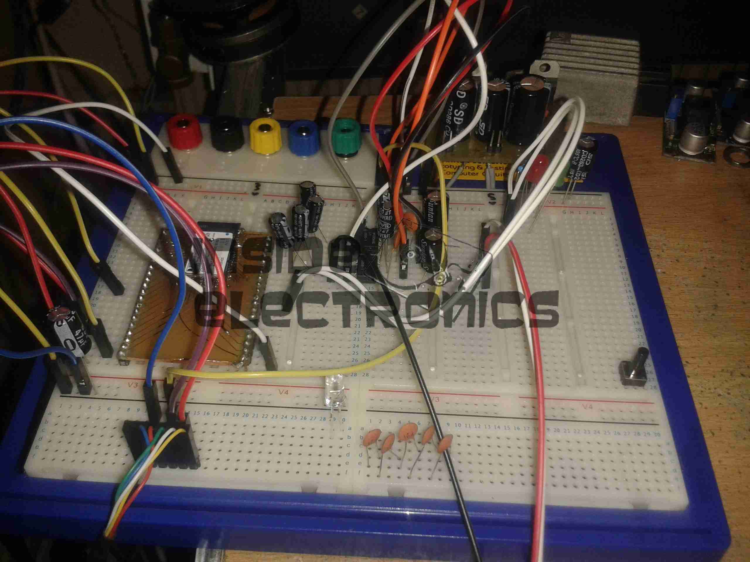
RN-52 Breadboard
Above is the current incarnation of the circuit on the breadboard. The RN-52 is on the left, audio power stage in the centre & headphone output on the right.
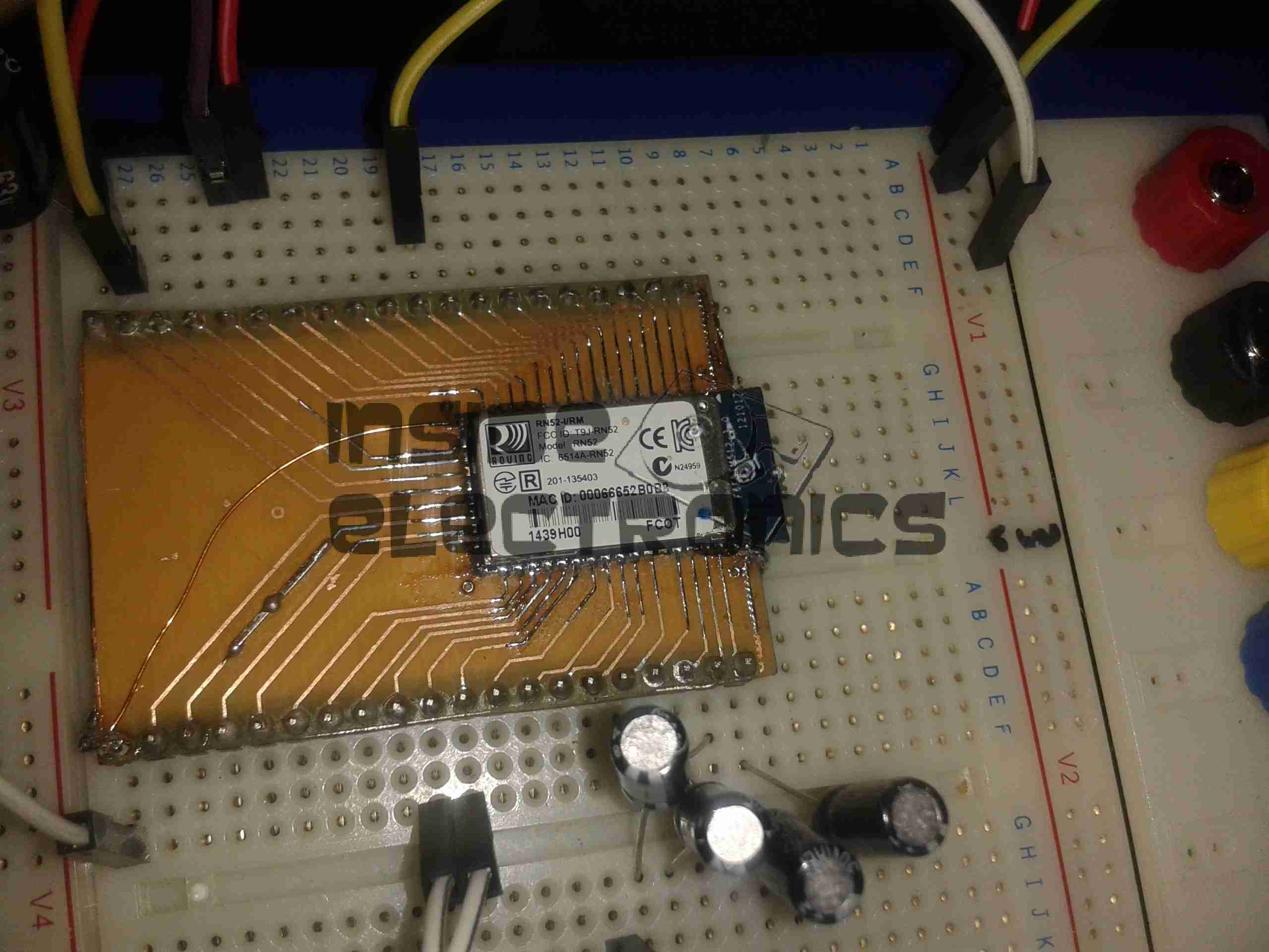
RN-52 Breakout
The bluetooth module on a breakout board. I was cheap in this case & etched my own board. I’m not paying Sparkfun, (as much as I like them), an extra ~£10 for a small PCB with the pins broken out. Much cheaper to spend 15 minutes with the laser printer & the iron, & do a toner transfer PCB.
As this board is single sided, I added a ground plane on the underside with copper foil, to help with the RF issues. Breadboards really aren’t all that good at rejecting noise induced when there’s a 2.4GHz transceiver mounted on them.
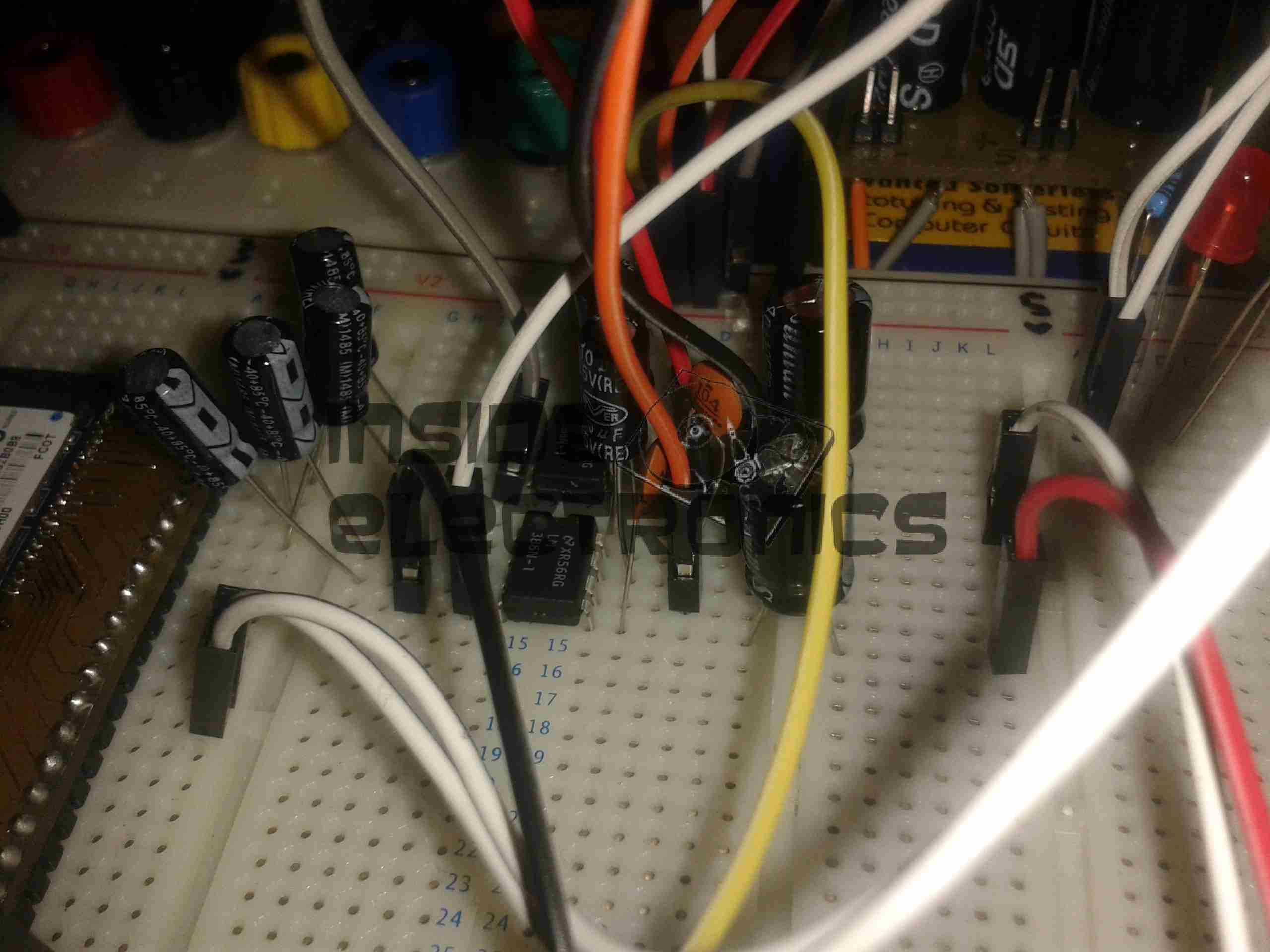
LM386 Amplifier
The LM386 audio power stage. The differential inputs from the module are capacitively coupled with 1µF electrolytics. This setup remarkably reduced the noise on the output. I left these at their default gain of 20, as I’ll be connecting another high power amplifier stage to drive large speakers.
RN-52 Eagle Layout
Here’s the circuit laid out in Eagle, ready for PCB.
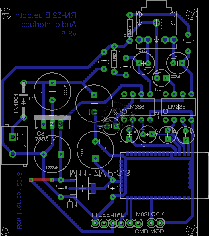
RN-52 Eagle PCB
And here’s the PCB layout. Only one link required for the +5v line from the TTL serial port.
As always, the Eagle PCB & Schematic layout files are available at the bottom of the article.
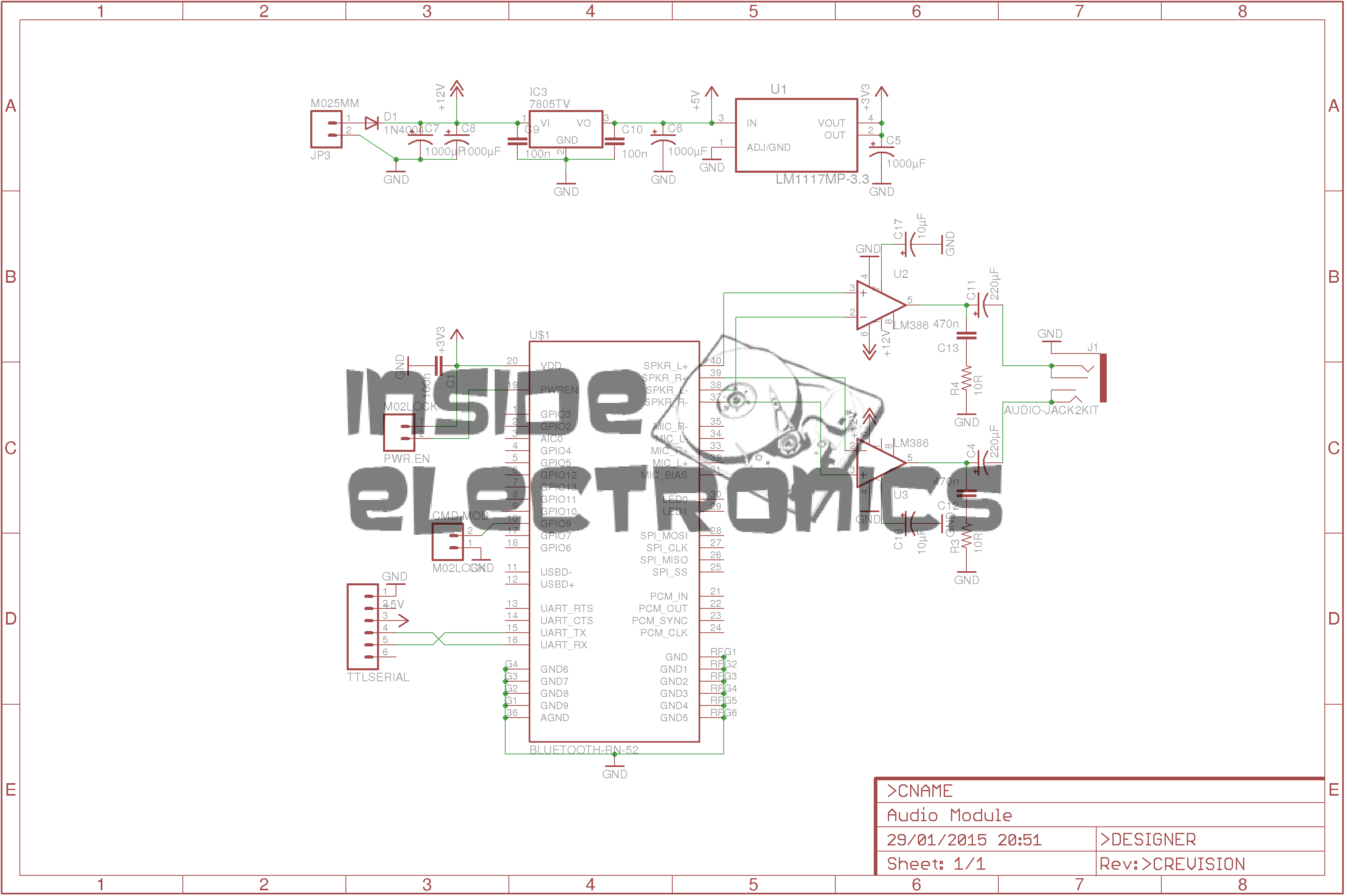
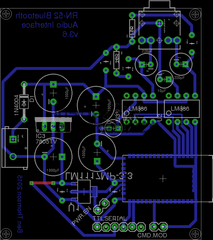
*Update 29-01-15*
Rerouted a few things:
Moved the audio power stage to the +12v rail to improve sound response. – As the LM386 has a max input voltage of 12v (absolute maximum 15v), a regulated supply is recommended. The LM386-N4 variant has a higher voltage range, up to 18v. This should be suitable for an unregulated supply.
Removed 1µF coupling capacitors to reduce distortion & amplifier hiss. The capacitors appeared to cause some instability on the amplifier, causing random distortion. Removing them has cured this. No signal hiss has also been reduced to a very low level.
Reversed input polarity on input of one of the amplifiers – this appears to produce better audio.
Added PWR.EN header to allow connection of power button. Saves hassle of cycling power to the board when the RN-52 goes into sleep mode.
This is a late 90’s business timeclock, used for maintaining records of staff working times, by printing the time when used on a sheet of card.
Front Internal
Here is the top cover removed, which is normally locked in place to stop tampering. The unit is programmed with the 3 buttons & the row of DIP switches along the top edge.
Instructions
Closeup of the settings panel, with all the various DIP switch options.
CPU & Display
Cover plate removed from the top, showing the LCD & CPU board, the backup battery normally fits behind this. The CPU is a 4-bit microcontroller from NEC, with built in LCD driver.
PSU & Drivers
Power Supply & prinhead drivers. This board is fitted with several NPN Darlington transistor arrays for driving the dox matrix printhead.
Printhead
Printhead assembly itself. The print ribbon fits over the top of the head & over the pins at the bottom. The drive hammers & solenoids are housed in the circular top of the unit.
Printhead Bottom
Bottom of the print head showing the row of impact pins used to create the printout.
Bottom of the solenoid assembly with the ribbon cable for power. There are 9 solenoids, to operate the 9 pins in the head.
Return Spring
Top layer of the printhead assembly, showing the leaf spring used to hold the hammers in the correct positions.
Hammers
Hammer assembly. The fingers on the ends of the arms push on the pins to strike through the ribbon onto the card.
Solenoids
The ring of solenoids at the centre of the assembly. These are driven with 3A darlington power arrays on the PSU board.
Gearbox Internals
There is only a single drive motor in the entire unit, that both clamps the card for printing & moves the printhead laterally across the card. Through a rack & pinion this also advances the ribbon with each print.
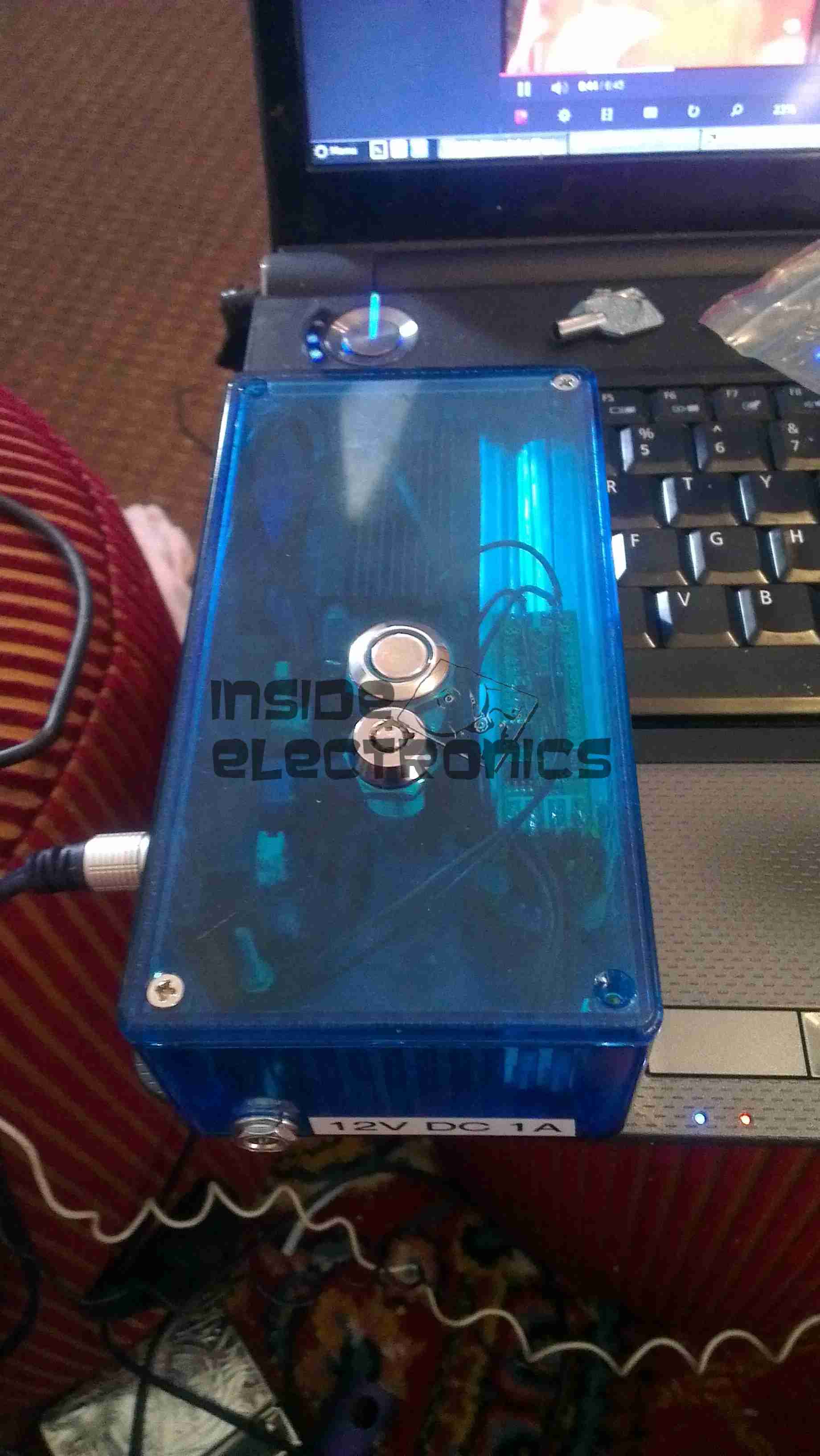
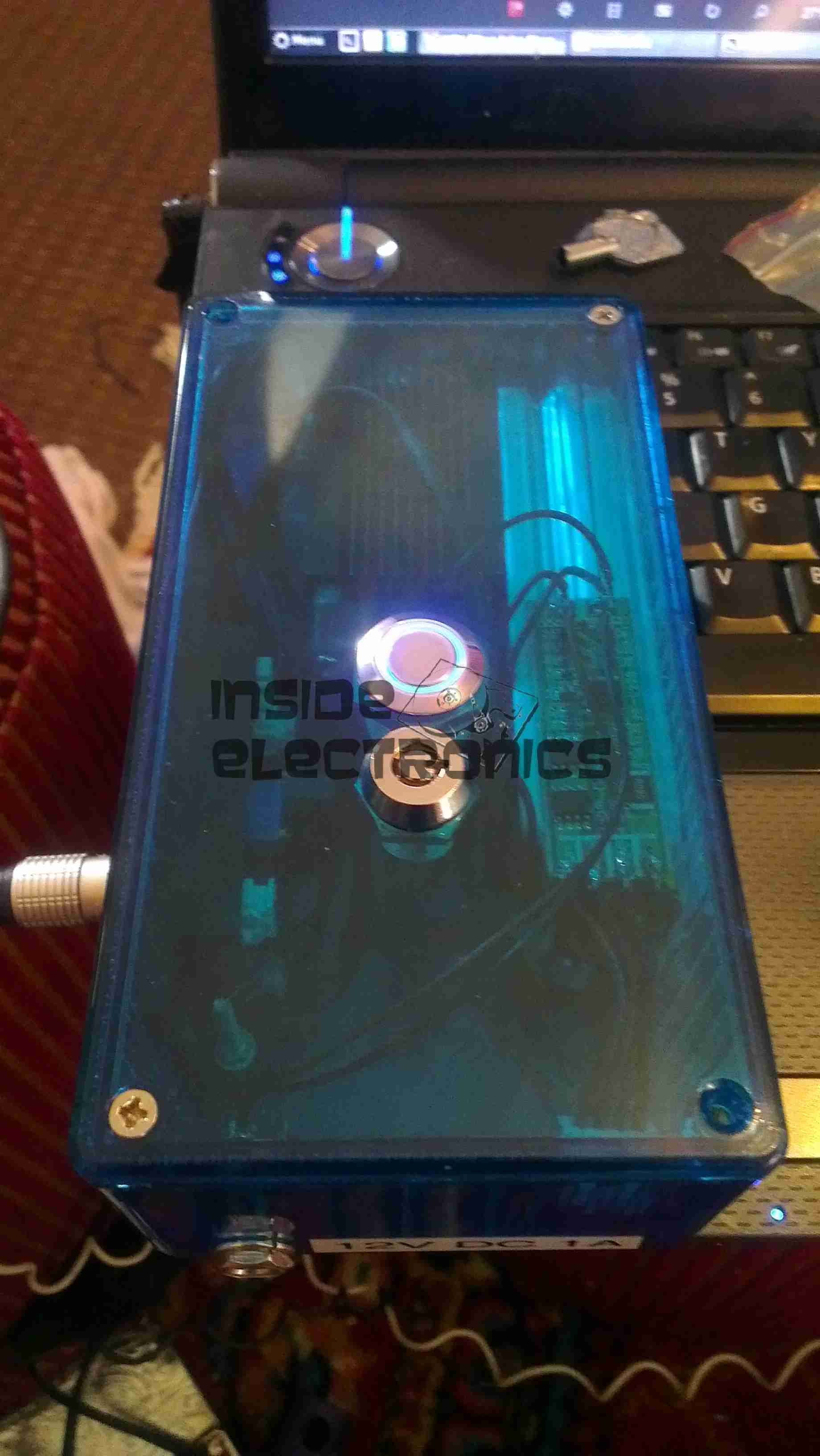
Here is a followup from the 1.5W laser module post.
The module has been fitted into a housing, with a 2.2Ah Li-Poly battery pack. Charging is accomplished with an external 12.6v DC power supply.
Above can be seen the pair of switches on the top, the keyswitch must be enabled for the laser to fire.
Armed
When armed, the ring around the push button illuminates blue, as a warning that the unit is armed.
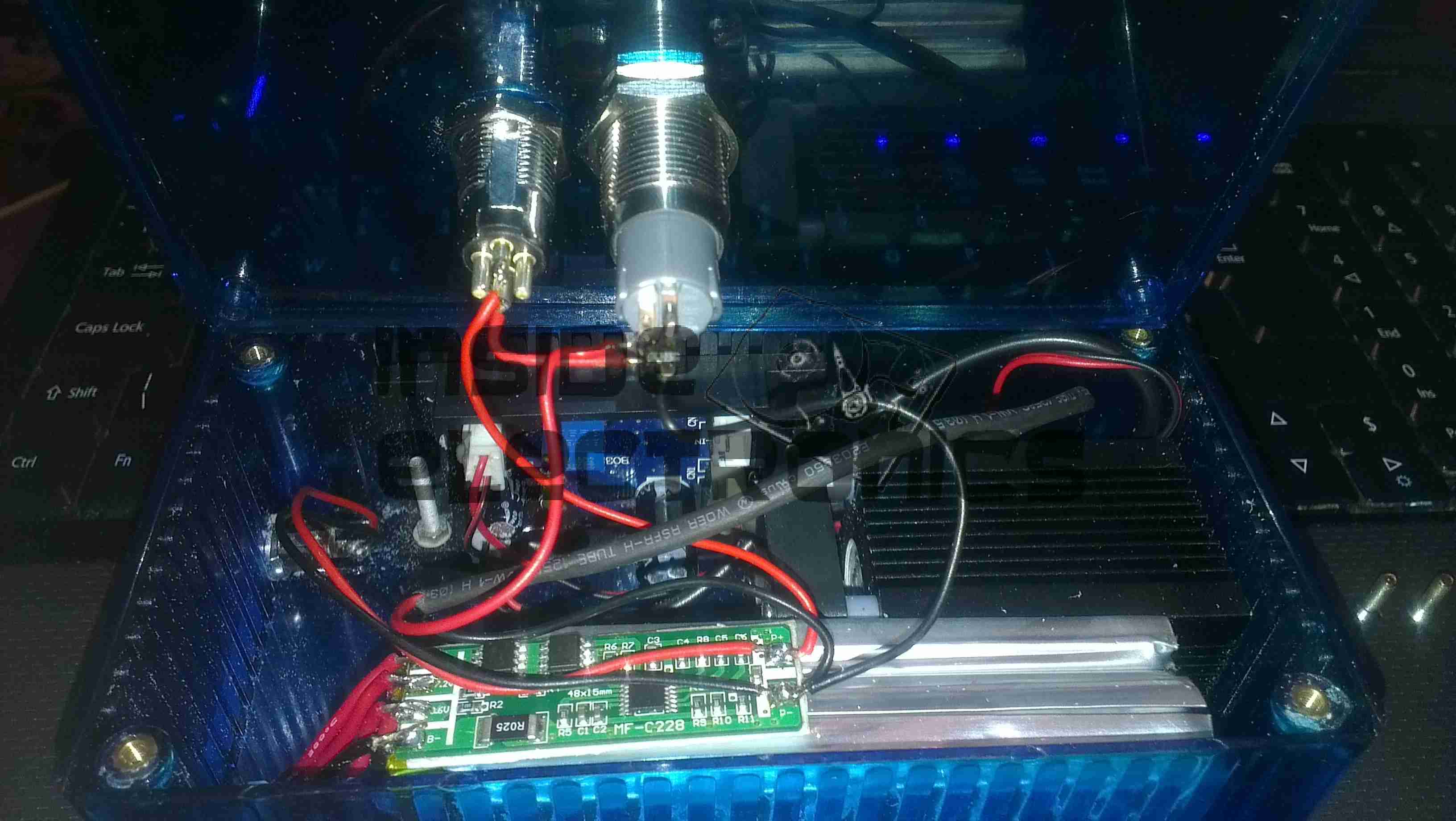
Switch Wiring
Inside the unit. The Li-Poly battery pack is at the bottom, with it’s protection & charging circuitry on the top. The switches are wired in series, with the LED connected to illuminate when the keyswitch is turned to the ON position.
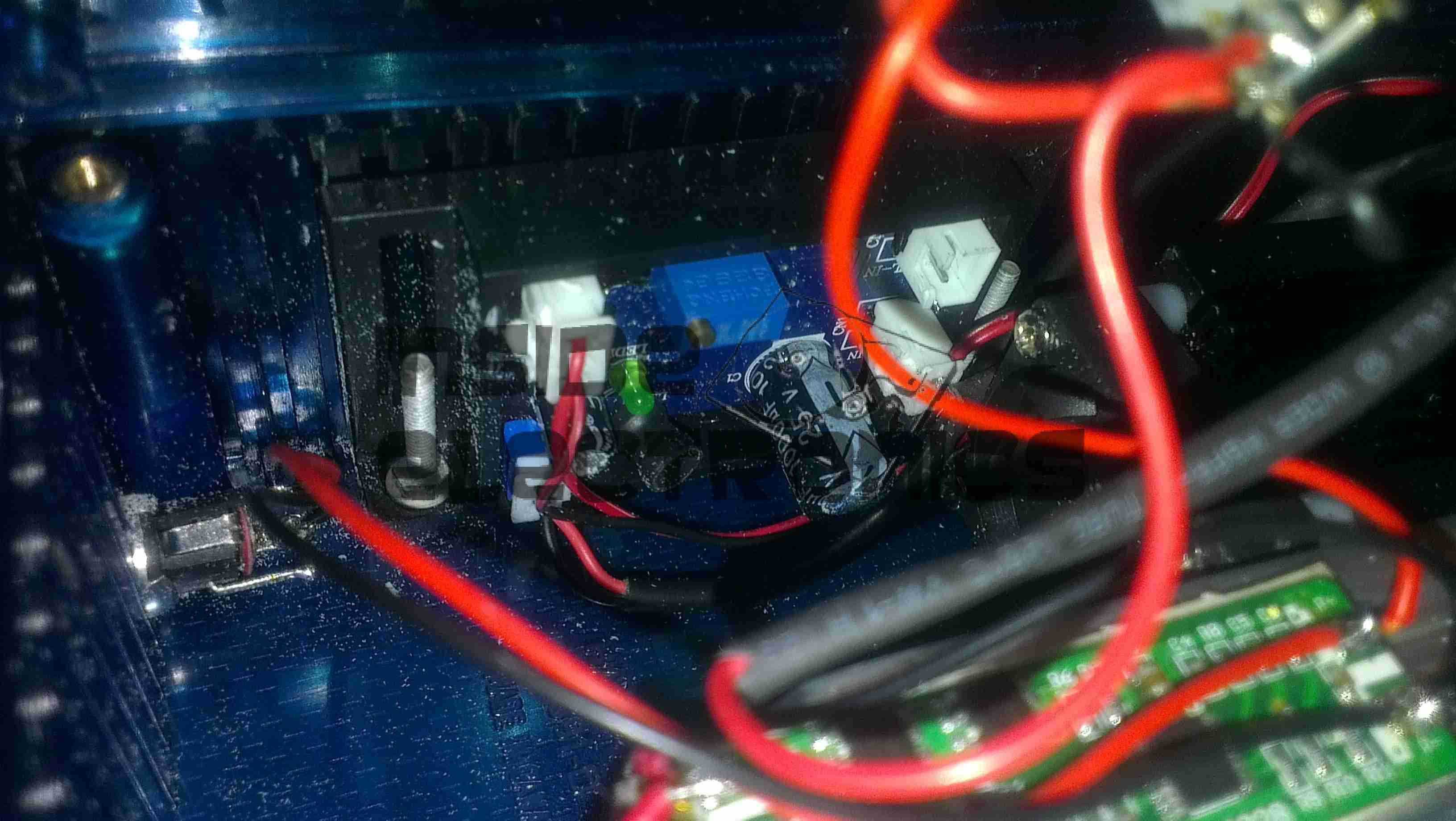
Laser Driver
The push button applies power to the laser driver module, which regulates the input power to safely drive the semiconductor laser in the aluminium heatsink housing.
Here is a SCSI U320 Ultrastar drive with a slight issue: the magnetic coating has been scrubbed off the substrate. I’ve never seen this happen to any other drive before.
The inside of the drive is coated with the resulting dust created from this rather epic failure mode.
I thought this would be of interest, as it’s from a drive circa 2001, (DVD-CD-RW).
It’s the biggest & most complex optical block I’ve ever seen, with totally separate beam paths for the IR CD beam & the visible DVD beam. It also combines the use of bare laser diodes & combined diode/photodiode array modules for the pickup.
Cover Removed
Here’s a look at the optics inside the sled, on the left is a bare laser diode & photodiode array, for the CD reading, and the bottom right has the DVD combined LD/PD array module. The beam from the CD diode has to pass though some very complex beam forming optics & a prism to fold it round to the final turning mirror to the objective lens at top center.
There are also two separate photodiodes which are picking up the waste beam from the prisms, most likely for power control.
This is the teardown of a Zebra P330i plastic card printer, used for creating ID cards, membership cards, employee cards, etc. I got this as a faulty unit, which I will detail later on.
This printer supports printing on plastic cards from 1-30mils thick, using dye sublimation & thermal transfer type printing methods. Interfaces supplied are USB & Ethernet. The unit also has the capability to be fitted with a mag stripe encoder & a smart card encoder, for extra cost.
Print Engine
On the left here is the print engine open, the blue cartridge on the right is a cleaning unit, using an adhesive roller to remove any dirt from the incoming card stock.
This is extremely important on a dye sublimation based printing engine as any dirt on the cards will cause printing problems.
Cards In Feeder
Here on the right is the card feeder unit, stocked with cards. This can take up to 100 cards from the factory.
The blue lever on the left is used to set the card thickness being used, to prevent misfeeds. There is a rubber gate in the intake port of the printer which is moved by this lever to stop any more than a single card from being fed into the print engine at any one time.
Card Feeder Belt
Here is the empty card feeder, showing the rubber conveyor belt. This unit was in fact the problem with the printer, the drive belt from the DC motor under this unit was stripped, preventing the cards from feeding into the printer.
Print Head
Here is a closeup of the print head assembly. The brown/black stripe along the edge is the row of thin-film heating elements. This is a 300DPI head.
Print Station
This is under the print head, the black roller on the left is the platen roller, which supports the card during printing. The spool in the center of the picture is the supply spool for the dye ribbon.
In the front of the black bar in the bottom center, is a two-colour sensor, used to locate the ribbon at the start of the Yellow panel to begin printing.
LCD PCB
Inside the top cover is the indicator LCD, the back of which is pictured right.
This is a 16×1 character LCD from Hantronix. This unit has a parallel interface.
LCD
Front of the LCD, this is white characters on a blue background.
Roller Drive Belts
Here is the cover removed from the printer, showing the drive belts powering the drive rollers. There is an identical arrangement on the other side of the print engine running the other rollers at the input side of the engine.
Mains Filter
Here the back panel has been removed from the entire print engine, complete with the mains input wiring & RFI filtering.
This unit has excellent build quality, just what is to be expected from a £1,200+ piece of industrial equipment.
Main Frame With Motors
The bottom of the print engine, with all the main wiring & PCB removed, showing the main drive motors. The left hand geared motor operates the head lift, the centre motor is a stepper, which operates the main transmission for the cards. The right motor drives the ribbon take up spindle through an O-Ring belt.
Feeder Drive Motor
Card feeder drive motor, this connects to the belt assembly through a timing belt identical to the roller drive system.
All these DC geared motors are 18v DC, of varying torque ratings.
Power Supply
Here is the main power supply, a universal input switch-mode unit, outputting 24v DC at 3.3A.
PSU Label
PSU info. This is obviously an off the shelf unit, manufactured by Hitek. Model number FUEA240.
Print Engine Rear
The PSU has been removed from the back of the print engine, here is shown the remaining mechanical systems of the printer.
Print Engine Components
A further closeup of the print engine mechanical bay, the main stepper motor is bottom centre, driving the brass flywheel through another timing belt drive. The O-Ring drive on the right is for the ribbon take up reel, with the final motor driving the plastic cam on the left to raise/lower the print head assembly.
The brass disc at the top is connected through a friction clutch to the ribbon supply reel, which provides tension to keep it taut. The slots in the disc are to sense the speed of the ribbon during printing, which allows the printer to tell if there is no ribbon present or if it has broken.
RFID PCB
Here is a further closeup, showing the RFID PCB behind the main transmission. This allows the printer to identify the ribbon fitted as a colour or monochrome.
The antenna is under the brass interrupter disc on the left.
I/O Daughterboard
The I/O daughterboard connects to the main CPU board & interfaces all the motors & sensors in the printer.
Main PCB
Here is the main CPU board, which contains all the logic & processing power in the printer.
CPU
Main CPU. This is a Freescale Semiconductor part, model number MCF5206FT33A, a ColdFire based 32-bit CPU. Also the system ROM & RAM can be seen on the right hand side of this picture.
Ethernet Interface
Bottom of the Ethernet interface card, this clearly has it’s own RAM, ROM & FPGA. This is due to this component being a full Parallel interface print server.
Ethernet Interface Top
Top of the PCB, showing the main processor of the print server. This has a ferrite sheet glued to the top, for interference protection.
Tip Jar
If you’ve found my content useful, please consider leaving a donation by clicking the Tip Jar below!
All collected funds go towards new content & the costs of keeping the server online.