Posted on 12 Comments

Zhiyu ZBP30A1 Electronic Dummy Load

60W DC Electronic Load

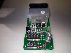
Here’s a useful tool for testing both power supplies & batteries, a dummy load. This unit is rated up to 60W, at voltages from 1v to 25v, current from 200mA to 9.99A.
This device requires a 12v DC power source separate from the load itself, to power the logic circuitry.
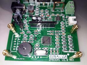
Microcontroller Section

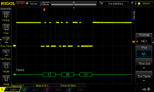
Like many of these modules, the brains of the operation is an STM8 microcontroller. There’s a header to the left with some communication pins, the T pin transmits the voltage when the unit is operating, along with the status via RS232 115200 8N1. This serial signal is only present in DC load mode, the pin is pulled low in battery test mode. The 4 pins underneath the clock crystal are the programming pins for the STM8.
Serial Comms
Serial Comms
Cooling Fan
Cooling Fan

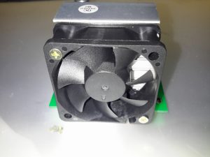
The main heatsink is fan cooled, the speed is PWM controlled via the microcontroller depending on the temperature.
Main MOSFET
Main MOSFET

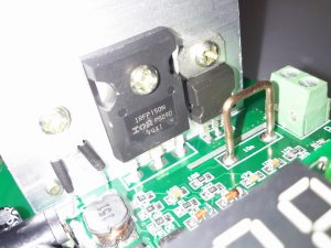
The main load MOSFET is an IRFP150N from Infineon. This device is rated at 100v 42A, with a max power dissipation of 160W. On the right is a dual diode for reverse polarity protection, this is in series with the MOSFET. On the left is the thermistor for controlling fan speed.
Load Terminals
Load Terminals

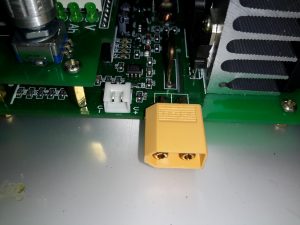
The load is usually connected via a rising clamp terminal block. I’ve replaced it with a XT60 connector in this case as all my battery holders are fitted with these. This also removes the contact resistance of more connections for an adaptor cable. The small JST XH2 connector on the left is for remote voltage sensing. This is used for 4-wire measurements.
Function 1 - DC Load
Function 1 – DC Load

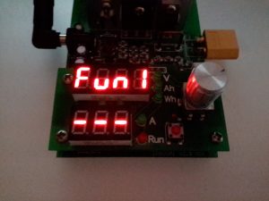
Powering the device up while holding the RUN button gets you into the menu to select the operating modes. Function 1 is simple DC load.

Function 2 - Battery Capacity Mode
Function 2 – Battery Capacity Mode

The rotary encoder is used to select the option. Function 2 is battery capacity test mode.
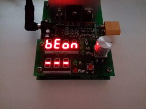
Beeper Mode
Beeper Mode

After the mode is selected, an option appears to either turn the beeper on or off.
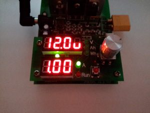
Amps Set
Amps Set

When in standby mode, the threshold voltage & the load current can be set. Here the Amps LED is lit, so the load current can be set. The pair of LEDs between the displays shows which digit will be changed. Pressing the encoder button cycles through the options.
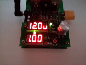
Volts Set
Volts Set

With the Volts LED lit, the threshold voltage can be changed.

When in DC load mode (Fun1), the device will place a fixed load onto the power source until it’s manually stopped. The voltage setting in this mode is a low-voltage alarm. The current can be changed while the load is running.

When in battery discharge test mode (Fun2), the voltage set is the cutoff voltage – discharge will stop when this is reached. Like the DC load mode, the current can be changed when the load is running. After the battery has completed discharging, the capacity in Ah & Wh will be displayed on the top 7-segment. These results can be selected between with the encoder.

Below are tables with all the options for the unit, along with the error codes I’ve been able to decipher from the Chinese info available in various places online. (If anyone knows better, do let me know!).

OptionFunction
Fun1Basic DC Load
Fun 2Battery Capacity Test
BeOnBeeper On
BeOfBeeper Off
Error CodeMeaning
Err1Input Overvoltage
Err2Low Battery Voltage / No Battery Present / Reverse Polarity
Err3Battery ESR Too High / Cannot sustain selected discharge current
Err4General Failure
Err6Power Supply Voltage Too Low / Too High. Minimum 12v 0.5A.
otPOvertemperature Protection
ErtTemperature Sensor Failure / Temperature Too Low
ouPPower Supply Overvoltage Protection
oPPLoad Power Protection
Posted on 4 Comments

AD9850 DDS VFO PCB & Schematic Layout

I recently came across a design for an Arduino controlled AD9850 DDS module, created by AD7C, so I figured I would release my Eagle CAD design for the PCB here.

It is a mainly single-sided layout, only a few links on the top side are needed so this is easy to etch with the toner transfer method.

My version uses an Arduino Pro Mini, as the modular format is much easier to work with than a bare ATMega 328.

RF output is via a SMA connector & has a built in amplifier to compensate for the low level generated by the DDS Module.

DDS VFO
DDS VFO

Version 2 Update: Added reverse polarity protection, added power indicator LED, beefed up tracks around the DC Jack.
[download id=”5571″]

Posted on Leave a comment

Zebra P330i Card Printer

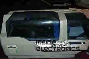
Front
Front

This is the teardown of a Zebra P330i plastic card printer, used for creating ID cards, membership cards, employee cards, etc. I got this as a faulty unit, which I will detail later on.
This printer supports printing on plastic cards from 1-30mils thick, using dye sublimation & thermal transfer type printing methods. Interfaces supplied are USB & Ethernet. The unit also has the capability to be fitted with a mag stripe encoder & a smart card encoder, for extra cost.

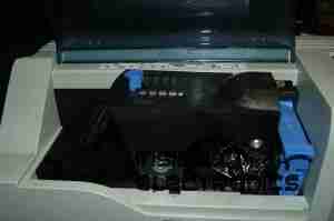
Print Engine
Print Engine


On the left here is the print engine open, the blue cartridge on the right is a cleaning unit, using an adhesive roller to remove any dirt from the incoming card stock.
This is extremely important on a dye sublimation based printing engine as any dirt on the cards will cause printing problems.

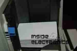
Cards In Feeder
Cards In Feeder


Here on the right is the card feeder unit, stocked with cards. This can take up to 100 cards from the factory.
The blue lever on the left is used to set the card thickness being used, to prevent misfeeds. There is a rubber gate in the intake port of the printer which is moved by this lever to stop any more than a single card from being fed into the print engine at any one time.

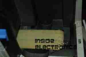
Card Feeder Belt
Card Feeder Belt


Here is the empty card feeder, showing the rubber conveyor belt. This unit was in fact the problem with the printer, the drive belt from the DC motor under this unit was stripped, preventing the cards from feeding into the printer.

Print Head
Print Head


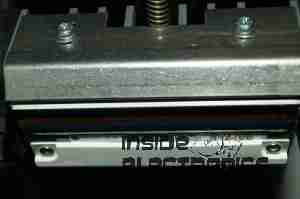
Here is a closeup of the print head assembly. The brown/black stripe along the edge is the row of thin-film heating elements. This is a 300DPI head.


Print Station
Print Station


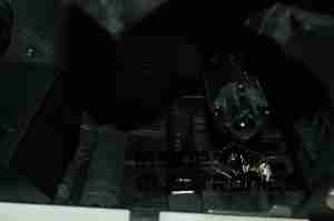
This is under the print head, the black roller on the left is the platen roller, which supports the card during printing. The spool in the center of the picture is the supply spool for the dye ribbon.
In the front of the black bar in the bottom center, is a two-colour sensor, used to locate the ribbon at the start of the Yellow panel to begin printing.

LCD PCB
LCD PCB


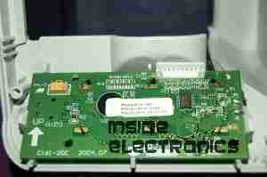
Inside the top cover is the indicator LCD, the back of which is pictured right.
This is a 16×1 character LCD from Hantronix. This unit has a parallel interface.

LCD
LCD


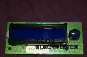
Front of the LCD, this is white characters on a blue background.

Roller Drive Belts
Roller Drive Belts


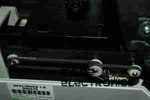
Here is the cover removed from the printer, showing the drive belts powering the drive rollers. There is an identical arrangement on the other side of the print engine running the other rollers at the input side of the engine.

Mains Filter
Mains Filter


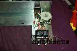
Here the back panel has been removed from the entire print engine, complete with the mains input wiring & RFI filtering.
This unit has excellent build quality, just what is to be expected from a £1,200+ piece of industrial equipment.

Main Frame With Motors


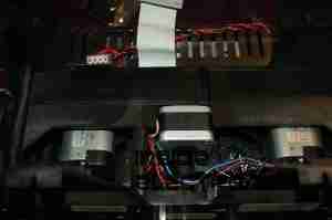
The bottom of the print engine, with all the main wiring & PCB removed, showing the main drive motors. The left hand geared motor operates the head lift, the centre motor is a stepper, which operates the main transmission for the cards. The right motor drives the ribbon take up spindle through an O-Ring belt.

Feeder Drive Motor
Feeder Drive Motor


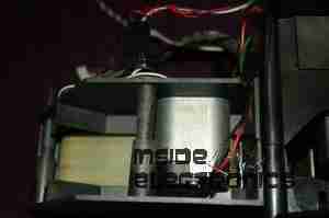
Card feeder drive motor, this connects to the belt assembly through a timing belt identical to the roller drive system.
All these DC geared motors are 18v DC, of varying torque ratings.

Power Supply
Power Supply


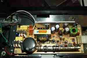
Here is the main power supply, a universal input switch-mode unit, outputting 24v DC at 3.3A.

PSU Label
PSU Label


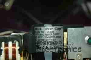
PSU info. This is obviously an off the shelf unit, manufactured by Hitek. Model number FUEA240.

Print Engine Rear
Print Engine Rear


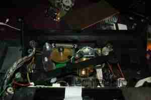
The PSU has been removed from the back of the print engine, here is shown the remaining mechanical systems of the printer.

Print Engine Components


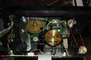
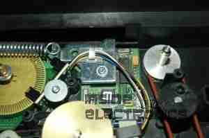
A further closeup of the print engine mechanical bay, the main stepper motor is bottom centre, driving the brass flywheel through another timing belt drive. The O-Ring drive on the right is for the ribbon take up reel, with the final motor driving the plastic cam on the left to raise/lower the print head assembly.
The brass disc at the top is connected through a friction clutch to the ribbon supply reel, which provides tension to keep it taut. The slots in the disc are to sense the speed of the ribbon during printing, which allows the printer to tell if there is no ribbon present or if it has broken.

RFID PCB
RFID PCB

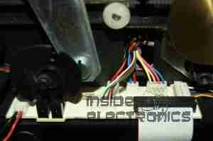
Here is a further closeup, showing the RFID PCB behind the main transmission. This allows the printer to identify the ribbon fitted as a colour or monochrome.
The antenna is under the brass interrupter disc on the left.

I/O Daughterboard
I/O Daughterboard


The I/O daughterboard connects to the main CPU board & interfaces all the motors & sensors in the printer.

Main PCB
Main PCB

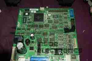
Here is the main CPU board, which contains all the logic & processing power in the printer.

CPU
CPU


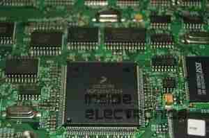
Main CPU. This is a Freescale Semiconductor part, model number MCF5206FT33A, a ColdFire based 32-bit CPU. Also the system ROM & RAM can be seen on the right hand side of this picture.

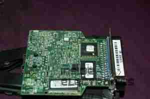
Ethernet Interface
Ethernet Interface


Bottom of the Ethernet interface card, this clearly has it’s own RAM, ROM & FPGA. This is due to this component being a full Parallel interface print server.

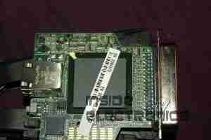
Ethernet Interface Top


Top of the PCB, showing the main processor of the print server. This has a ferrite sheet glued to the top, for interference protection.


Posted on 1 Comment

MSR605 3-Track Magnetic Stripe Writer

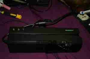
MSR605
MSR605

This unit was bought from eBay to experiment with Magnetic Stripe cards, for little money. This unit is capable of reading & writing all 3 tracks, & both Hi-Co & Lo-Co card types.
Interfaced to a PC through USB, this has a built in PL2303 USB-Serial IC & requires 3A at 9v DC to operate.
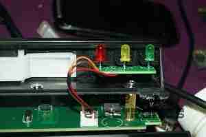
The 3 Indicator LEDs on the top of the unit can be toggled by the included software for Power/OK/Fault condition signalling.

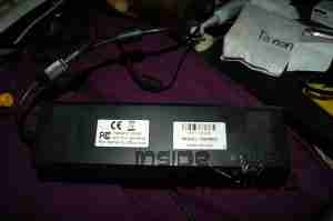
Unit Bottom
Unit Bottom

Bottom of the unit with the model labels.

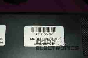
Model Label
Model Label

Closeup of the model label & serial number.

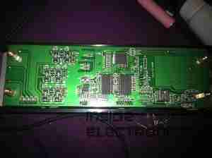
PCB Bottom
PCB Bottom

Here the bottom cover has been removed, showing the main PCB. The pair of large ICs bottom center interface with the magnetic heads. The IC above them has had the markings sanded off.

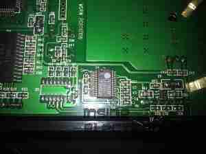
USB-Serial Interface

Closeup of the Prolific PL-2303 USB-Serial converter IC.

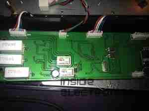
PCB Top
PCB Top

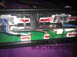
Here the connections to the R/W heads are visible, current limiting resistors at the left for the write head, a pair of signal relays, a pair of optoisolators & a LM7805 linear voltage regulator.

LEDs
LEDs

Here is the trio of indicator LEDs on a small sub-board.

Frame Bottom
Frame Bottom

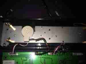
The PCB has been removed from the main frame here, the only component visible is the rotary encoder.

Rotary Encoder
Rotary Encoder

The rotary encoder has a rubber wheel fitted, which reads the speed of the card as it is being swiped for writing. This allows the control logic to write the data to the stripe at the correct rate for the speed of the card. This allows the unit to write cards from 5-50 inches per second speed.
The Write head is directly behind the rubber pressure roller.

Read/Write Heads
Read/Write Heads

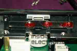
Here you can see the R/W head assembly. The write head is on the right, read on the left. When a card is written to, it immediately gets read by the second head for verification.

The drivers for this unit are also available here: Magcard Writer Drivers

Posted on Leave a comment

Logitech Cordless Ball Mouse

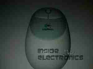
Top
Top

This is an old legacy wireless mouse from Logitech. This uses a ball rather than optical technology.

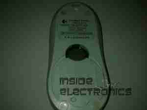
Bottom
Bottom

Bottom of the mouse, showing the battery cover & the mouse ball.

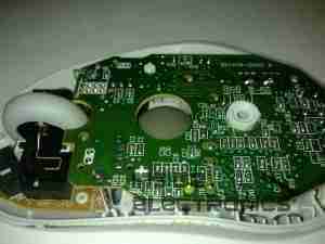
PCB Bottom
PCB Bottom

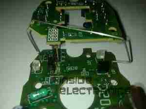
Top removed from the mouse, showing the PCB inside. The smaller PCB on the left supports the microswitches for the buttons & mouse wheel.

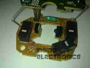
Switches
Switches

Closeup of small PCB showing the microswitches & the IR LED & phototransistor pair for the mouse wheel encoder.

Main PCB
Main PCB

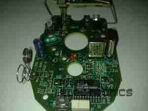
View of main PCB, with interface IC lower right. Pair of quartz crystals provide clocking for the transmitter & internal µC.
Battery contacts are on lower left of the PCB. At the top are the IR pairs for the X & Y axis of the mouse ball.

Encoder Pairs
Encoder Pairs

Closeup of the pairs of IR LEDs & phototransistors that make up the encoders for X/Y movement of the mouse, together with the slotted wheels in the mouse base that rotate with the ball. Steel wire around the smaller PCB is the antenna.

Posted on Leave a comment

HP Photosmart 375

Top
Top

This is a HP PhotoSmart 375 portable photo printer. With built in card reader, screen & PictBridge.
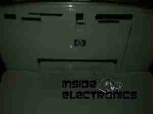
Top of the printer showing the UI Buttons & Screen.

Front
Front

Front of the unit, card reader slots at the top, Pictbridge USB connector at top left. Paper out slot at bottom. Cartridge door is on the right.

Cartridge Door
Cartridge Door

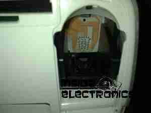
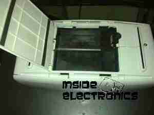
Here the cartridge door is open. Takes HP 95 Tri-Colour Inkjet Cartridge.

Battery Compartment
Battery Compartment

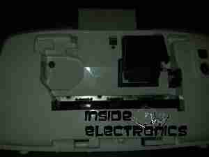
Battery compartment on the bottom of the unit. A Li-Ion battery pack can be installed here for mobile photo printing.

Bottom Label
Bottom Label

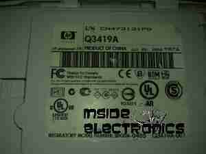
Specifications label.

USB + Power
USB + Power

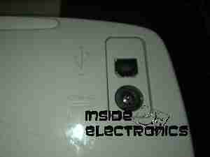
Power adaptor & USB connection for PC use.

Paper Tray
Paper Tray

Rear door opened. Showing the paper feed tray.

Paper Feeder
Paper Feeder

Rear door has been removed in this shot. Paper feed roller & platen roller can be seen here.

Rear Cover Paper Feeder

Paper holder attached to rear door.

Top Cover
Top Cover

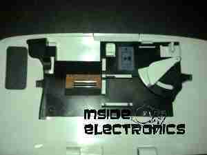
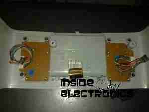
Bottom of the top cover, with connections for the buttons & LCD panel.

Main PCB
Main PCB

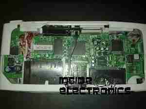
This is the main PCB of the unit. Controls all aspects of the printer. CPU in center, card reader sockets are along bottom edge. various support circuitry surrounds the CPU.

Rear
Rear

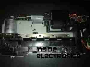
Rear shell has been removed here. Showing the main frame & the carriage drive motor on the left.

Carriage Drive
Carriage Drive

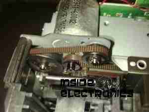
Closeup of the carriage drive motor & timing belt system. All the motors in this printer are DC servo motors, not steppers.

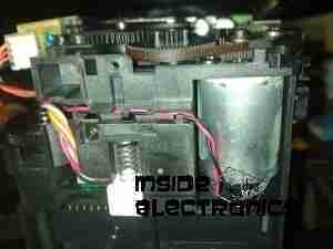
Main Drive Motor
Main Drive Motor

Main drive motor, feeds paper, drives rollers, operates cleaning mechanism for the inkjets.

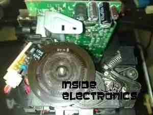
Shaft Encoder
Shaft Encoder

Mainshaft encoder. Main drive motor is bottom right hand side with timing belt drive.

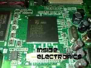
CPU
CPU

Closeup of the CPU. This is a Phillips ARM chip, unknown spec.

Card Reader Sockets
Card Reader Sockets

Detail of the card reader sockets, this unit takes all current types of Flash memory card.

HP 95 Tri-color Inkjet Print Cartridge