Posted on Leave a comment

First Alert CO-FA-9B Carbon Monoxide Alarm Teardown

CO-FA-9B Alarm
CO-FA-9B Alarm

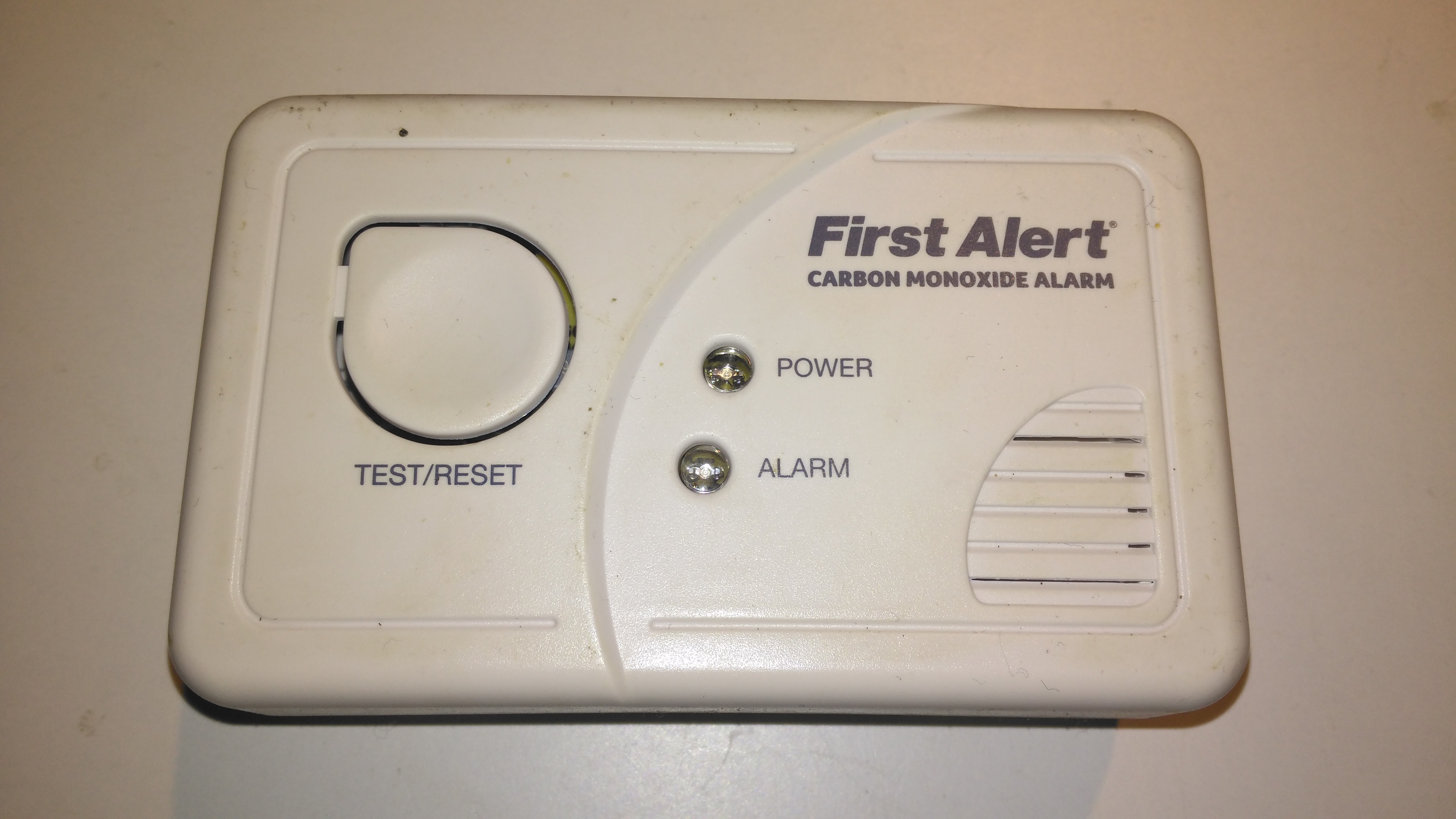
Here’s another domestic CO Alarm, this one a cheaper build than the FireAngel ones usually use, these don’t have a display with the current CO PPM reading, just a couple of LEDs for status & Alarm.

Rear
Rear

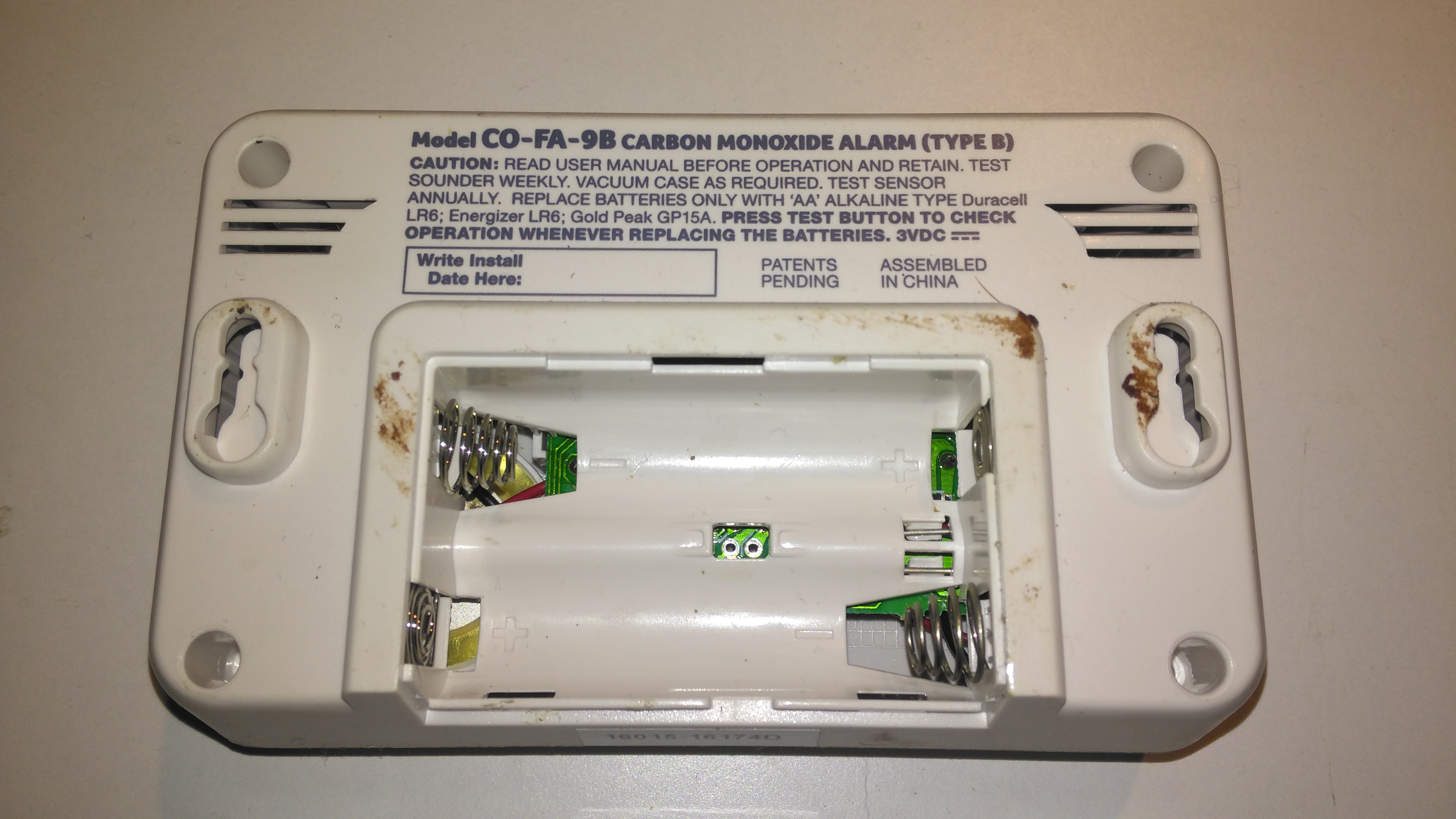
This alarm also doesn’t have the 10-year lithium cell for power, taking AA cells instead. The alarm does have the usual low battery alert bleeps common with smoke alarms though, so you’ll get a fair reminder to replace them.

Internals
Internals

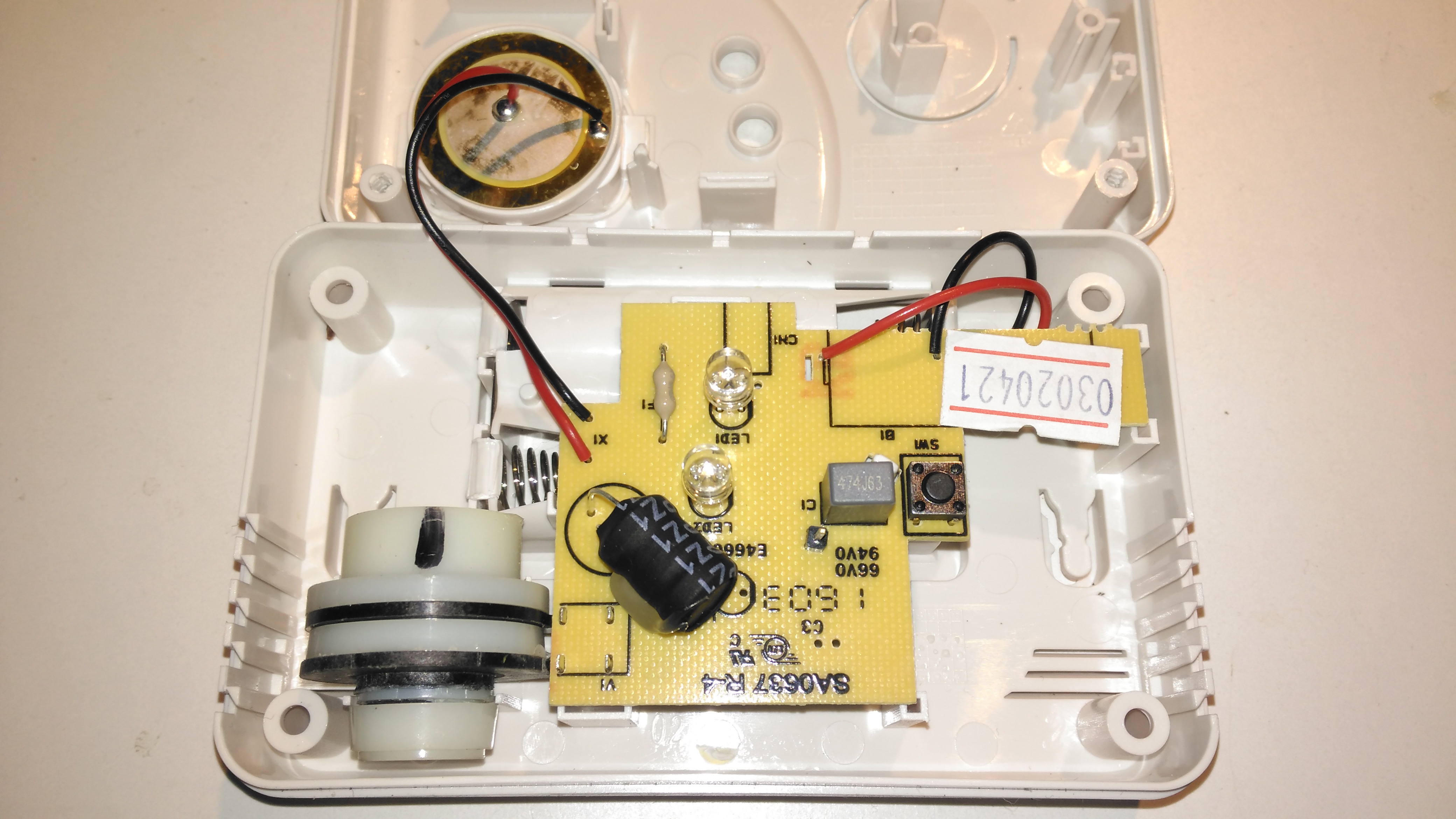
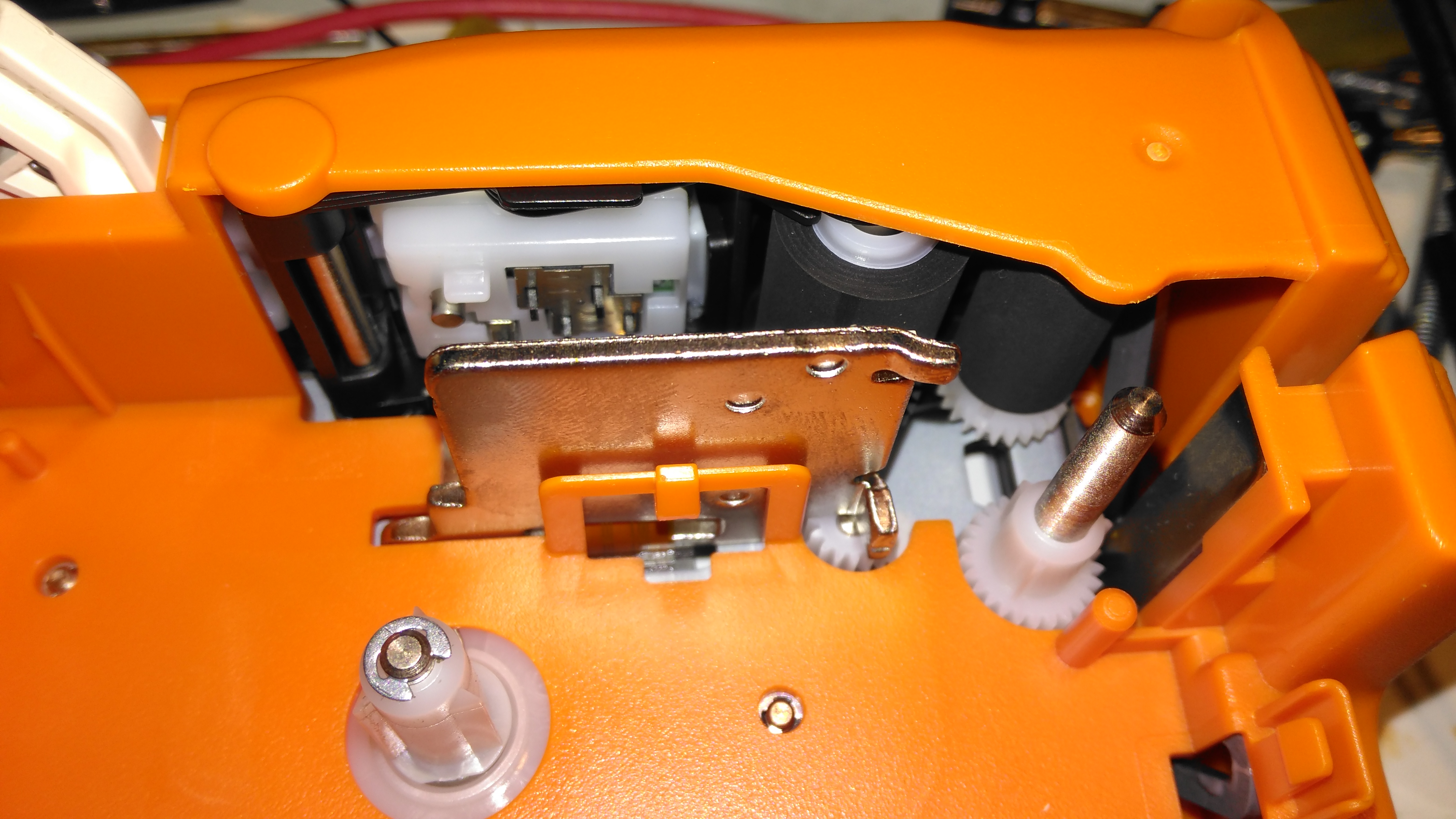
Not much at all on the inside. The CO sensor cell is the same one as used in the FireAngel alarms, I have never managed to find who manufactures these sensors, or a datasheet for them unfortunately.

PCB Top
PCB Top

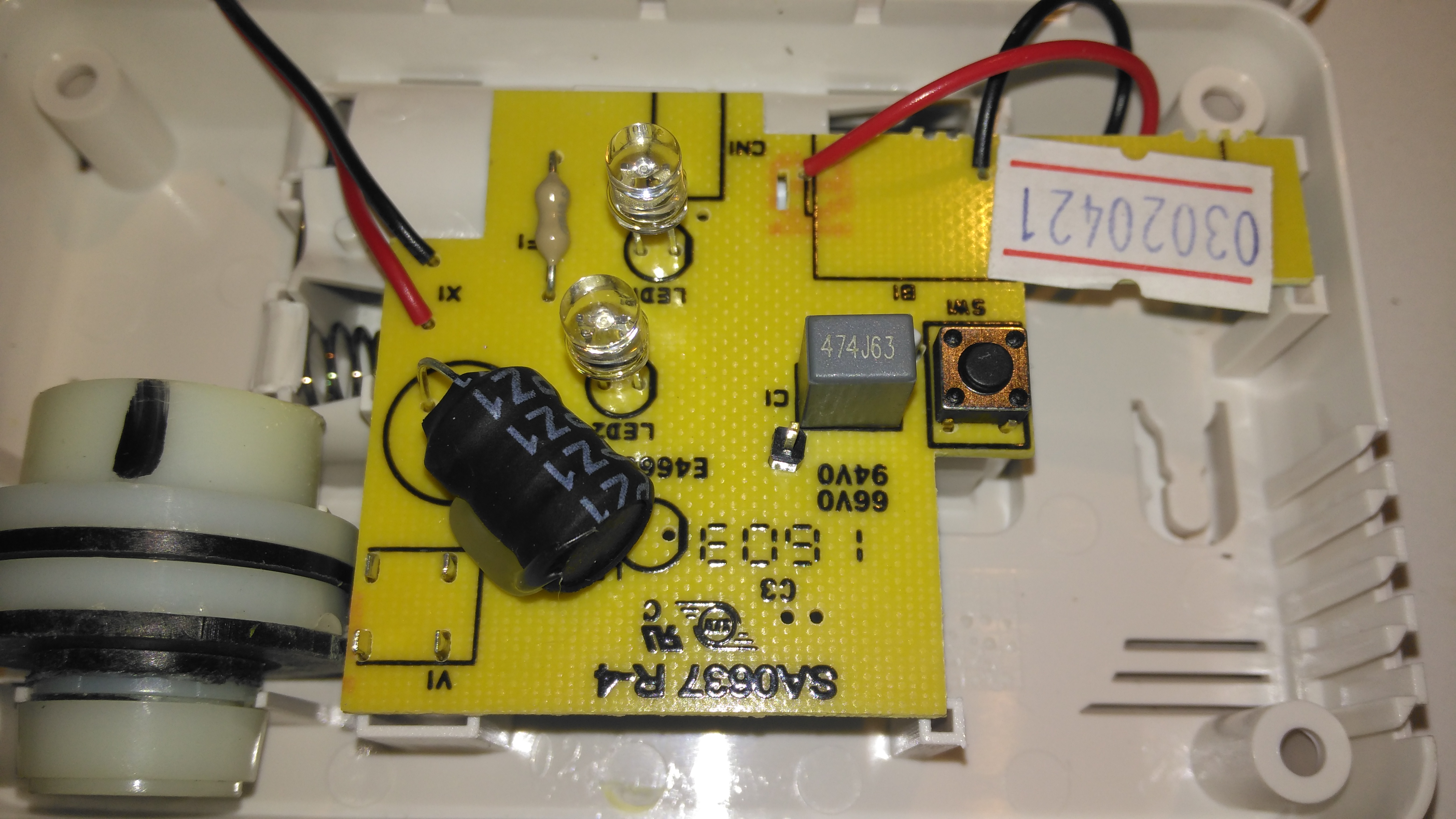
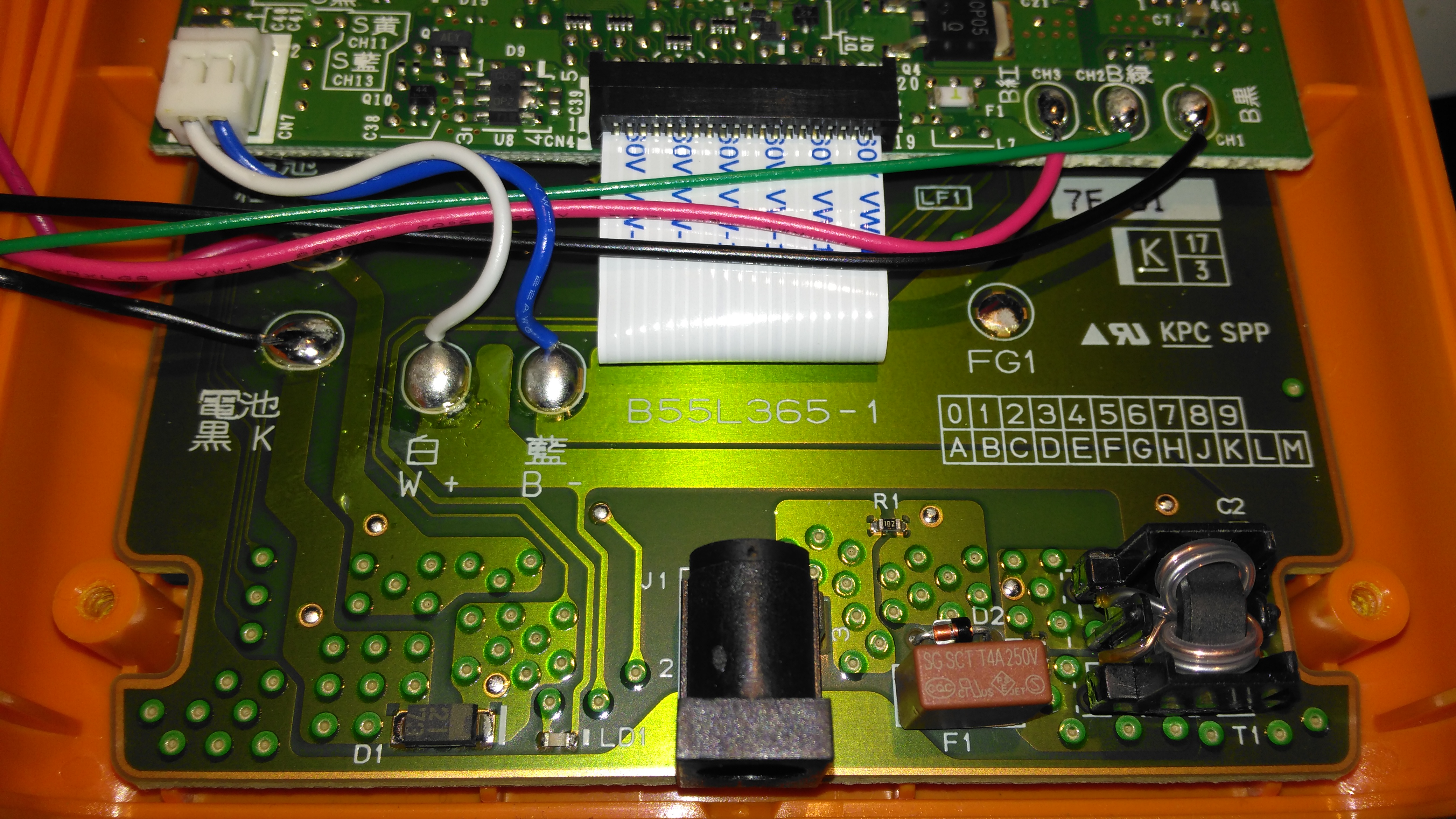
The top of the single sided PCB has the transformer for driving the Piezo sounder, the LEDs & the test button.

PCB Bottom
PCB Bottom

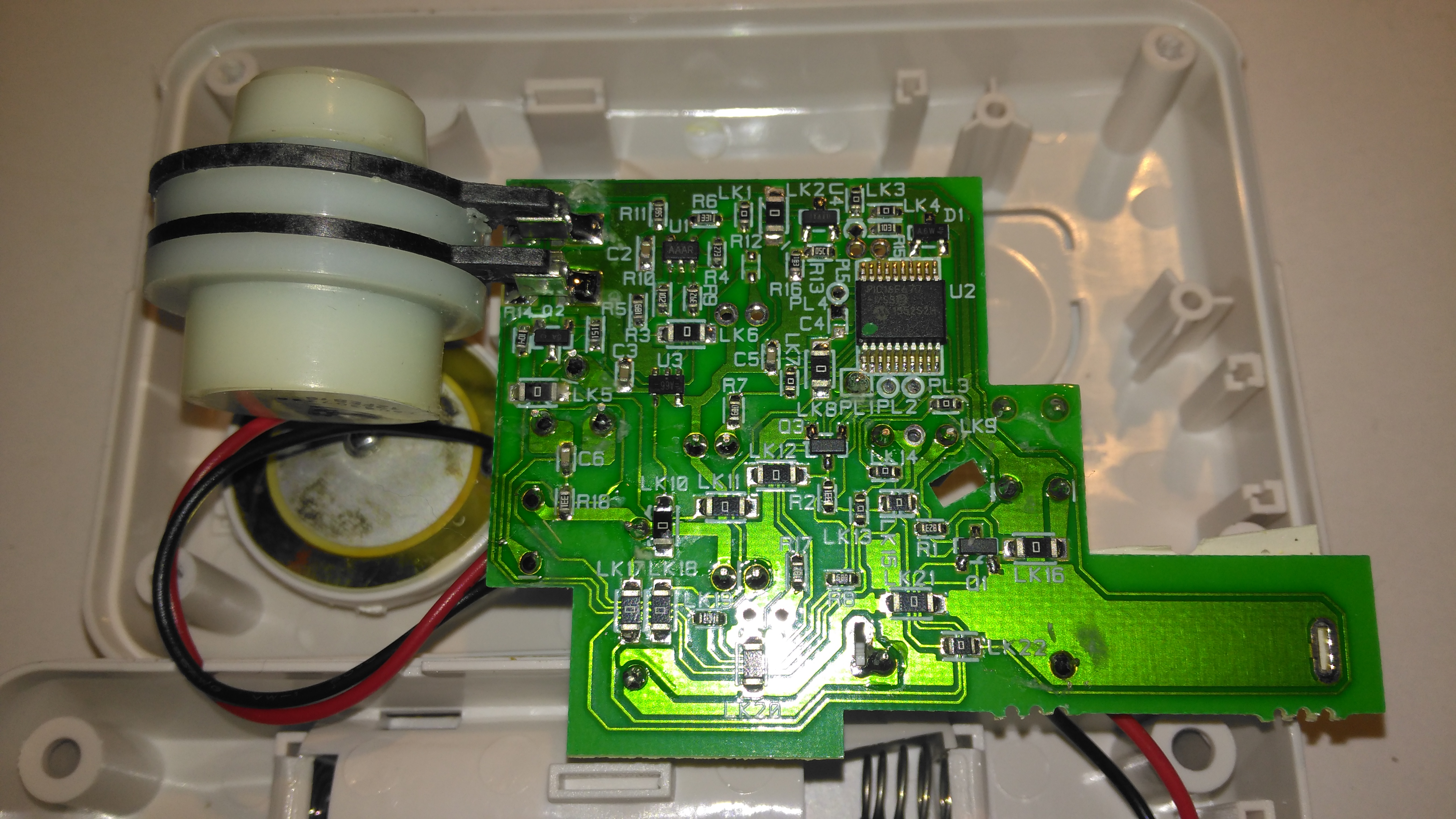
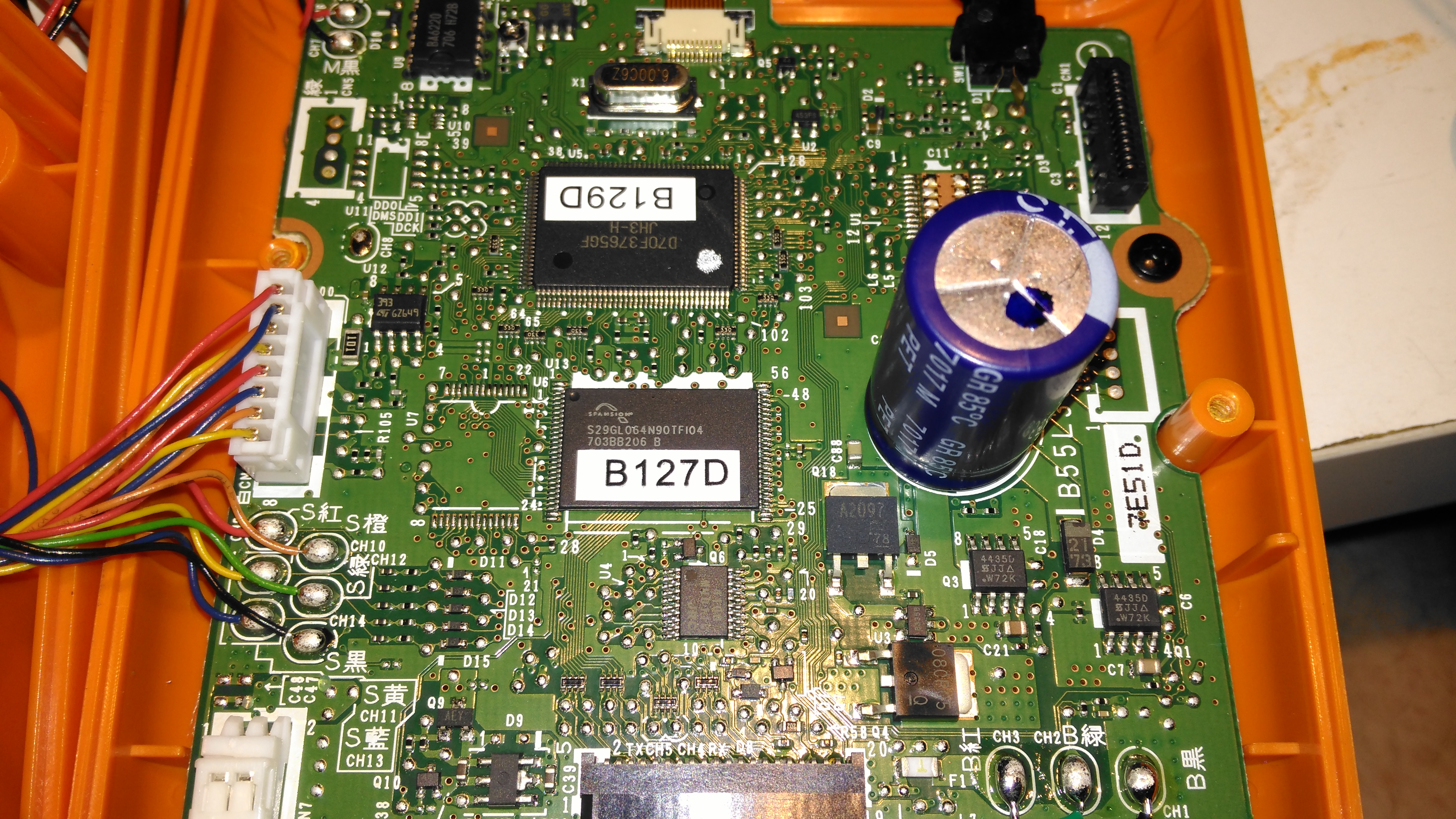
All the magic happens on the bottom of the PCB. The controlling microcontroller is on the top right, with the sensor front end on the top left.

Circuitry Closeup
Circuitry Closeup

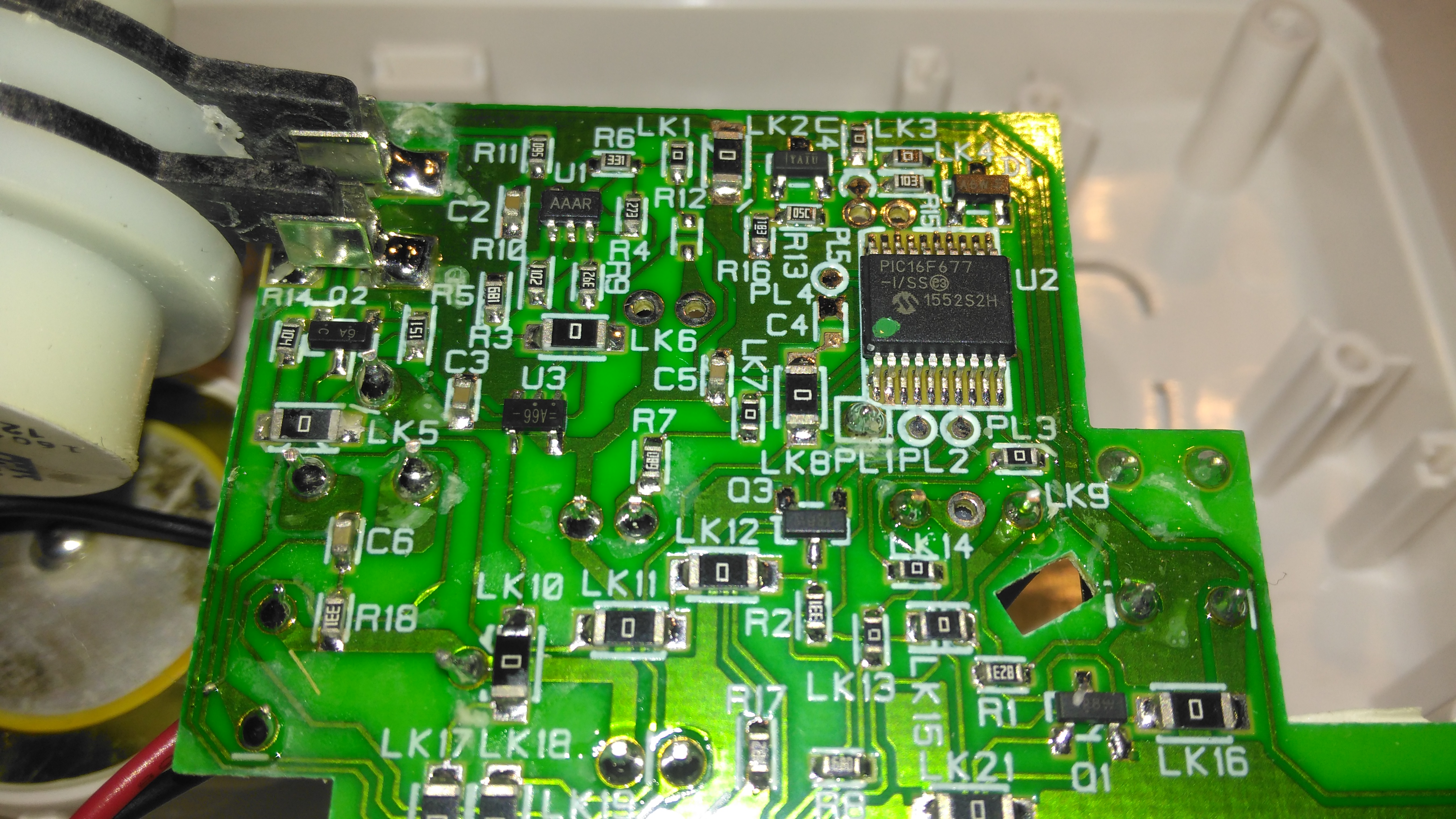
The microcontroller used here is a Microchip PIC16F677. I’ve not managed to find datasheets for the front end components, but these will just be a low-noise op-amp & it’s ancillaries. There will also be a reference voltage regulator. The terminals on these sensors are made of conductive plastic, probably loaded with carbon.

Sensor Cell & Piezo Disc

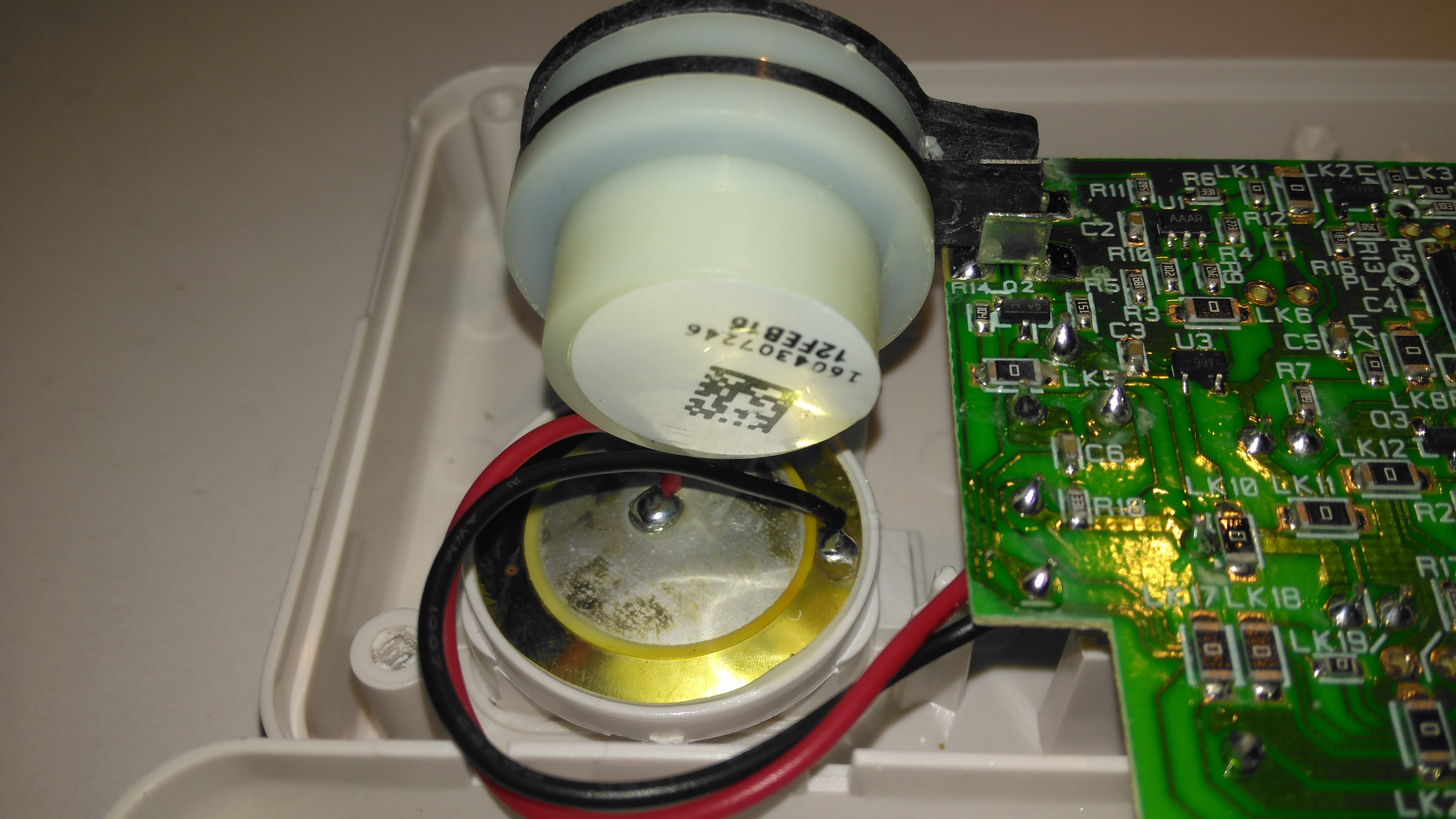
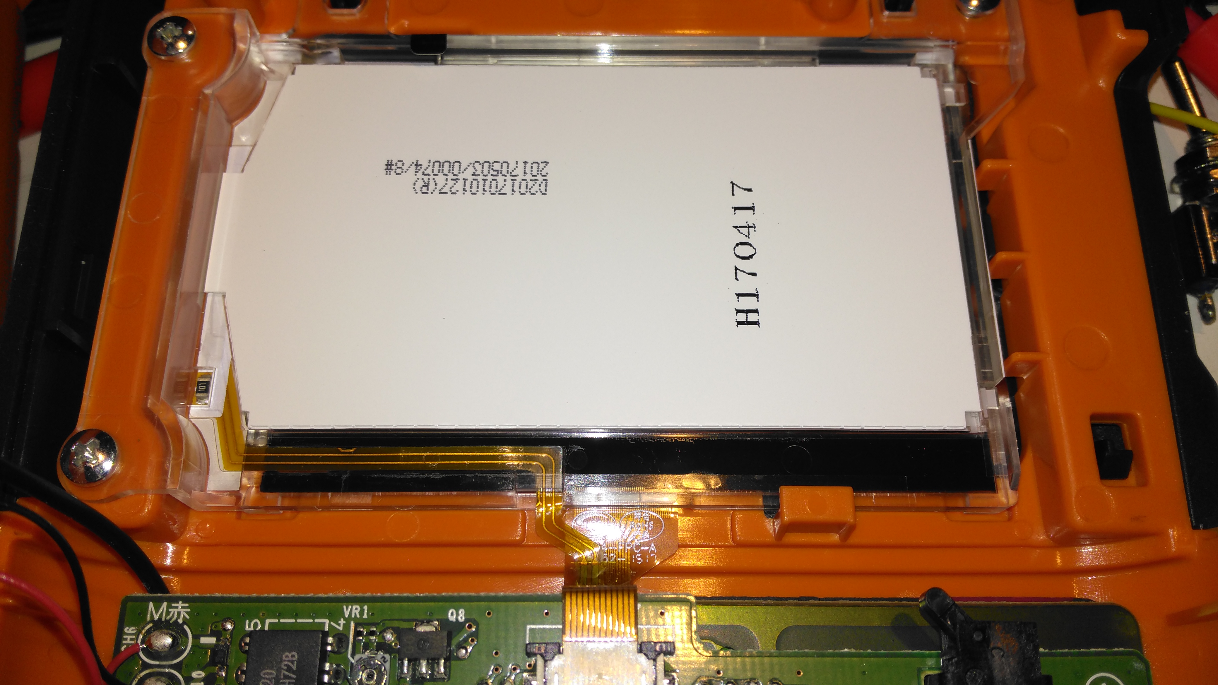
The expiry date is handily on a label on the back of the sensor, the Piezo sounder is just underneath in it’s sound chamber.

Posted on 1 Comment

Brother PT-E300 Industrial Label Machine Teardown

Tape Installed
Tape Installed

Here a tape is installed in the printer. This unit can handle tape widths up to 18mm. The pinch rollers are operated by the white lever at the top of the image, which engages with the back cover.

Li-Ion Battery
Li-Ion Battery

This printer is supplied with a rechargeable battery pack, but AA cells can be used as well. Some of the AA battery terminals can be seen above the battery.

Battery Specs
Battery Specs

Pretty standard fare for a 2-cell lithium pack. The charging circuitry doesn’t appear to charge it to full voltage though, most likely to get the most life from the pack.

Cartridge Slot
Cartridge Slot

With the cartridge removed, the printer components can be seen. As these cartridges have in effect two rolls, one fro the ribbon & one for the actual label, there are two drive points.

Pinch Rollers & Print Head

The thermal print head is hidden on the other side of the steel heatsink, while the pinch rollers are on the top right. The plastic piece above the print head heatsink has a matrix of switches that engage with holes in the top of the label cartridge, this is how the machine knows what size of ribbon is fitted.

Mainboard
Mainboard

Most of the internal space is taken up by the main board, with the microprocessor & it’s program flash ROM top & centre.

Charger Input
Charger Input

The charger input is located on the keyboard PCB just under the mainboard, which is centre negative, as opposed to 99% of other devices using centre positive, the bastards.

LCD Module
LCD Module

The dot-matrix LCD is attached to the mainboard with a short flex cable, and from the few connections, this is probably SPI or I²C.

Print Mech Drive
Print Mech Drive

The printer itself is driven by a simple DC motor, speed is regulated by a pair of photo-interrupters forming an encoder on the second gear in the train.

Battery Holder Connections

The back case has the battery connections for both the lithium pack & the AA cells, the lithium pack has a 3rd connection, probably for temperature sensing.

Posted on Leave a comment

Vivicam 5190

Front
Front

A 5 megapixel digital camera from Vivitar. Visible here is the lens, viewfinder & flash.

Back
Back

Rear of the unit showing the LCD & user control buttons.

Cover Removed
Cover Removed

Front frame removed showing some of the internals. Shutter assembly & lens in centre, battery compartment at left.

Rear Cover Removed
Rear Cover Removed

Rear frame removede, showing the LCD module & tactile switches.

LCD
LCD

LCD module removed from the PCB

Flash PCB
Flash PCB

Flash PCB removed. Transformer is fed with the 4.5v from the 3 AA cells & steps it up to ~300v DC for the flash capacitor. A pulse transformer energizes an electrode next to the Xenon flash tube with ~5kV to ionize the gas.

Main PCB
Main PCB

Main PCB removed. Internal flash ROM & RAM IC visible above the SD card socket. USB connector is at the top right, next to the piezo buzzer.

CPU
CPU

Main processor on reverse side of the PCB.

Image Sensor
Image Sensor

Closeup of the CMOS image sensor with the lens assembly removed.

Posted on Leave a comment

Logitech Cordless Ball Mouse

Top
Top

This is an old legacy wireless mouse from Logitech. This uses a ball rather than optical technology.

Bottom
Bottom

Bottom of the mouse, showing the battery cover & the mouse ball.

PCB Bottom
PCB Bottom

Top removed from the mouse, showing the PCB inside. The smaller PCB on the left supports the microswitches for the buttons & mouse wheel.

Switches
Switches

Closeup of small PCB showing the microswitches & the IR LED & phototransistor pair for the mouse wheel encoder.

Main PCB
Main PCB

View of main PCB, with interface IC lower right. Pair of quartz crystals provide clocking for the transmitter & internal µC.
Battery contacts are on lower left of the PCB. At the top are the IR pairs for the X & Y axis of the mouse ball.

Encoder Pairs
Encoder Pairs

Closeup of the pairs of IR LEDs & phototransistors that make up the encoders for X/Y movement of the mouse, together with the slotted wheels in the mouse base that rotate with the ball. Steel wire around the smaller PCB is the antenna.