Posted on Leave a comment

PSi 150 Power Inverter

Front
Front

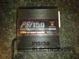
This is a small 120W power inverter, intended for small loads such as lights, fans, small TVs & laptop computers.
End Cover
End Cover

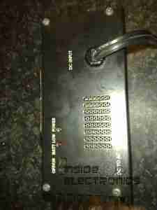
End cover of the unit, 12v DC input cord at the top, power switch & indicator LEDs at the bottom.
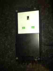
Mains Output
Mains Output

Opposite end of the unit, with the standard 240v AC 50Hz Mains output socket.
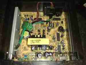
Cover Removed
Cover Removed

Cover removed from the top of the unit. Main power transformer is visible in the centre here, MOSFET bank is under the steel clamp on the left, the aluminium case forms the heatsink.
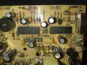
PWM Controllers
PWM Controllers

On the right is a KA3525 switchmode PWM controller & on the left is a LM324N quad Op-Amp IC. The buzzer on the far left is for the low battery warning.
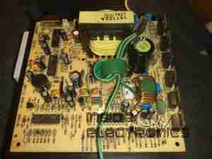
PCB Removed
PCB Removed

PCB removed from the casing, with the MOSFET bank on the right hand side. Two potentiometers in the centre of the board tweak the frequency of the switcher & the output voltage.
 

Posted on Leave a comment

Vivicam 5190

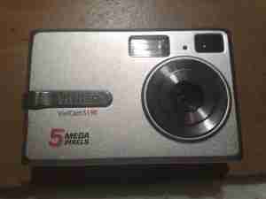
Front
Front

A 5 megapixel digital camera from Vivitar. Visible here is the lens, viewfinder & flash.

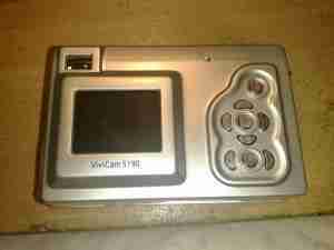
Back
Back

Rear of the unit showing the LCD & user control buttons.

Cover Removed
Cover Removed

Front frame removed showing some of the internals. Shutter assembly & lens in centre, battery compartment at left.

Rear Cover Removed
Rear Cover Removed

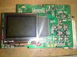
Rear frame removede, showing the LCD module & tactile switches.

LCD
LCD

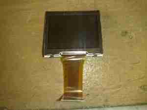
LCD module removed from the PCB

Flash PCB
Flash PCB

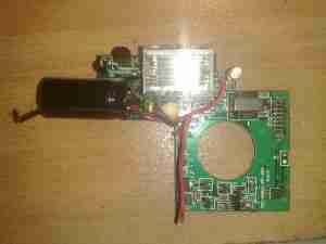
Flash PCB removed. Transformer is fed with the 4.5v from the 3 AA cells & steps it up to ~300v DC for the flash capacitor. A pulse transformer energizes an electrode next to the Xenon flash tube with ~5kV to ionize the gas.

Main PCB
Main PCB

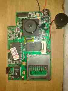
Main PCB removed. Internal flash ROM & RAM IC visible above the SD card socket. USB connector is at the top right, next to the piezo buzzer.

CPU
CPU

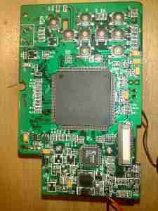
Main processor on reverse side of the PCB.

Image Sensor
Image Sensor

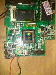
Closeup of the CMOS image sensor with the lens assembly removed.

Posted on Leave a comment

Uniden Stalker Radar Detector

Top
Top

An early speed radar detector from the early 90’s. Pictures showing the front of the unit with the option buttons.

Bottom
Bottom

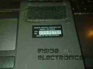
Bottom of the unit showing label. Unlike the newer plastic detectors, the whole casing of this unit is cast aluminium.
Model Uniden Stalker RD-6000W.

PCB Top
PCB Top

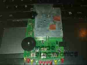
PCB removed from the casing. Volume/power control on the left. Option tactile switches on the edge of the PCB, with the indicator LEDs. Power input jack on the right hand side of the PCB. Large aluminium can is the detector assembly, containing the detector diodes. Waveguide horn is at the top.

Waveguide Horn
Waveguide Horn

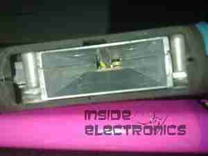
Shot down the waveguide, showing the detector diodes at the end.

LEDs
LEDs

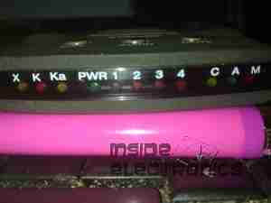
Indicators on the front of the unit, X, K & Ka band detection LEDs on the left, Power & detection level (1-4) LEDs in centre. City (C) (Audio (A) & Mute (M) LEDs on the right.

PCB Bottom
PCB Bottom

Bottom of the PCB, showing detection logic. Piezo buzzer top left.

CPU
CPU

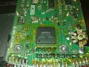
Custom Uniden CPU. Marking UC1465.

Posted on Leave a comment

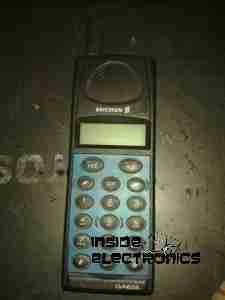
Ericsson GA628

Front
Front

Here is a phone from the mid 90s, the Ericsson GA628. Here visible is the front of the unit with keypad, & single line monochrome LCD for number display.

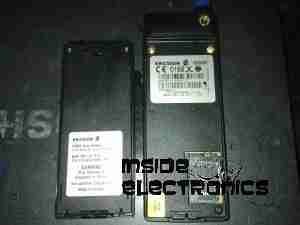
Battery & Rear
Battery & Rear

Here the battery is removed from the phone, showing the SIM card socket. At the top under the antenna stub is the socket for an external antenna.

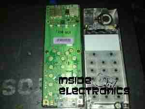
Front Removed
Front Removed

Here the front is removed from the phone, PCB on left, rear of keypad on right. Microphone is at bottom of keypad, with speaker at the top. Top right of the PCB is the ringer buzzer, left is shield for RF amplifier.

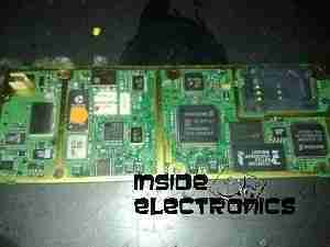
Main PCB
Main PCB

Here is the back of the main PCB, RF sections on left & centre. Processing & memory on right.

Battery
Battery

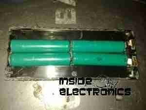
This phone had a Ni-Mh battery, before Li-Ion batteries were introduced.

LCD
LCD

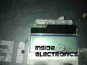
The LCD from the front of the phone is shown here. A simple dot matrix single line unit.