A while back I found myself in the need of an adjustable RF attenuator capable of high-GHz operation. As luck would have it I had an old Spectrum analyser on the shelf at work, which we had retired quite some time ago.
Spectrum analysers being quite capable test instruments, I knew that the input attenuation would be done with a standalone module that we could recover for reuse without too much trouble.
The attenuator module
Here’s the module itself, with the factory drive PCB removed from the bottom, showing the solenoids that operate the RF switches. There are test wires attached to them here to work out which solenoid switches which attenuation stage. In the case of this module, there are switches for the following:
Input select switch
AC/DC coupling
-5dB
-10dB
-20dB
-40dB
For me this means I have up to -75dB attenuation in 5dB steps, with optional switchable A-B input & either AC or DC coupling.
Drive is easy, requiring a pulse on the solenoid coil to switch over, the polarity depending on which way the switch is going.
Building a Control Board
Now I’ve identified that the module was reusable, it was time to spin up a board to integrate all the features we needed:
Onboard battery power
Pushbutton operation
Indication of current attenuation level
The partially populated board is shown at right, with an Arduino microcontroller for main control, 18650 battery socket on the right, and control buttons in the centre. The OLED display module for showing the current attenuation level & battery voltage level is missing at the moment, but it’s clear where this goes.
As there weren’t enough GPIO pins for everything on the Arduino, a Microchip MC23017 16-Bit I/O expander, which is controlled via an I²C bus. This is convenient since I’m already using I²C for the onboard display.
Driving the Solenoids
A closer view of the board shows the trip of dual H-Bridge drivers on the board, which will soon be hidden underneath the attenuator block. These are LB1836M parts from ON Semiconductor. Each chip drives a pair of solenoids.
Power Supplies
The bottom of the board has all the power control circuitry, which are modularised for ease of production. There’s a Lithium charge & protection module for the 18650 onboard cell, along with a boost converter to give the ~9v rail required to operate the attenuator solenoids. While they would switch at 5v, the results were not reliable.
Finishing off
A bit more time later, some suitable firmware has been written for the Arduino, and the attenuator block is fitted onto the PCB. The onboard OLED nicely shows the current attenuation level, battery level & which input is selected.
I’m making some changes to my hosting services, I’ve been testing Sentora, as it’s much more user friendly, if a little more limited in what it’s capable of doing, vs my go-to admin panel over the past 6+ years, Virtualmin.
I noticed that SpamAssassin isn’t set up on a Sentora server by default, so here’s a script that will get things working under a fresh Sentora install in CentOS 7:
After this script has run, some mail server settings will be changed, and the master.cf configuration file for Postfix will be backed up just in case it craps out.
Make sure the SpamAssassin daemon is running on port 783 with this command:
ss -tnlp | grep spamd
Testing is easy, send an email to an address hosted by Sentora with the following in the subject line:
If SpamAssassin is working correctly, this will be tagged with a spam score of 999.
A useful script is below, this trains SpamAssassin on the mail in the current server mailboxes. I’ve been using a version of this for a long time, this one is slightly modified to operate with Sentora’s vmail system. All mail for all domains & users will be fed into SpamAssassin in this script. I set this to run nightly in cron.
#!/bin/bash

#specify one or more users, space padded [user=(user1 user2 user3)] or empty [user=()] to include all users. All users is considered uid ≥ 1000.
user=(vmail)

#After how many days should Spam be deleted?
cleanafter=30

#backup path, comment out to disable backups
bk=/home/backup/sa-learn_bayes_`date +%F`.backup

log=/var/log/train-mail.log
#log=/dev/stdout

echo -e "\n`date +%c`"  >> $log 2>&1

if [ -z ${user[@]} ]; then
echo user is empty, using all users from system
user=(`awk -F':' '$3 >= 1000 && $3 < 65534' /etc/passwd |awk -F':' '{print $1}'`)
fi

for u in ${user[@]}; do
if [ ! -d /var/sentora/vmail/*/* ]; then
echo "No such Maildir for $u" >> $log 2>&1
else
echo "Proceeding with ham and spam training on user \"$u\""
#add all messages in "junk" directory to spamassassin
echo spam >> $log 2>&1
#change this path to match your spam directory, in this case its "Junk"
#add current and new messages in Junk directory as spam
sa-learn --no-sync --spam /var/sentora/vmail/*/*/.Junk/{cur,new} >> $log 2>&1
echo ham >> $log 2>&1
#only add current mail to ham, not new. This gives user a chance to move it to spam dir.
sa-learn --no-sync --ham /var/sentora/vmail/*/*/{cur} >> $log 2>&1
fi
done

#sync the journal created above with the database
echo sync >> $log 2>&1
sa-learn --sync >> $log 2>&1
if [ $? -eq 0 ]; then
for u in ${user[@]}; do
echo "deleting spam for $u older than 30 days" >> $log 2>&1
find /var/sentora/vmail/*/*/.Junk/cur/ -type f -mtime +$cleanafter -exec rm {} \;
done
else
echo "sa-learn wasn't able to sync. Something is broken. Skipping spam cleanup"
fi

echo "Statistics:" >> $log 2>&1
sa-learn --dump magic >> $log 2>&1
echo ============================== >> $log 2>&1

if [ -n $bk ]; then
echo "backup writing to $bk" >> $log 2>&1
sa-learn --backup > $bk
fi
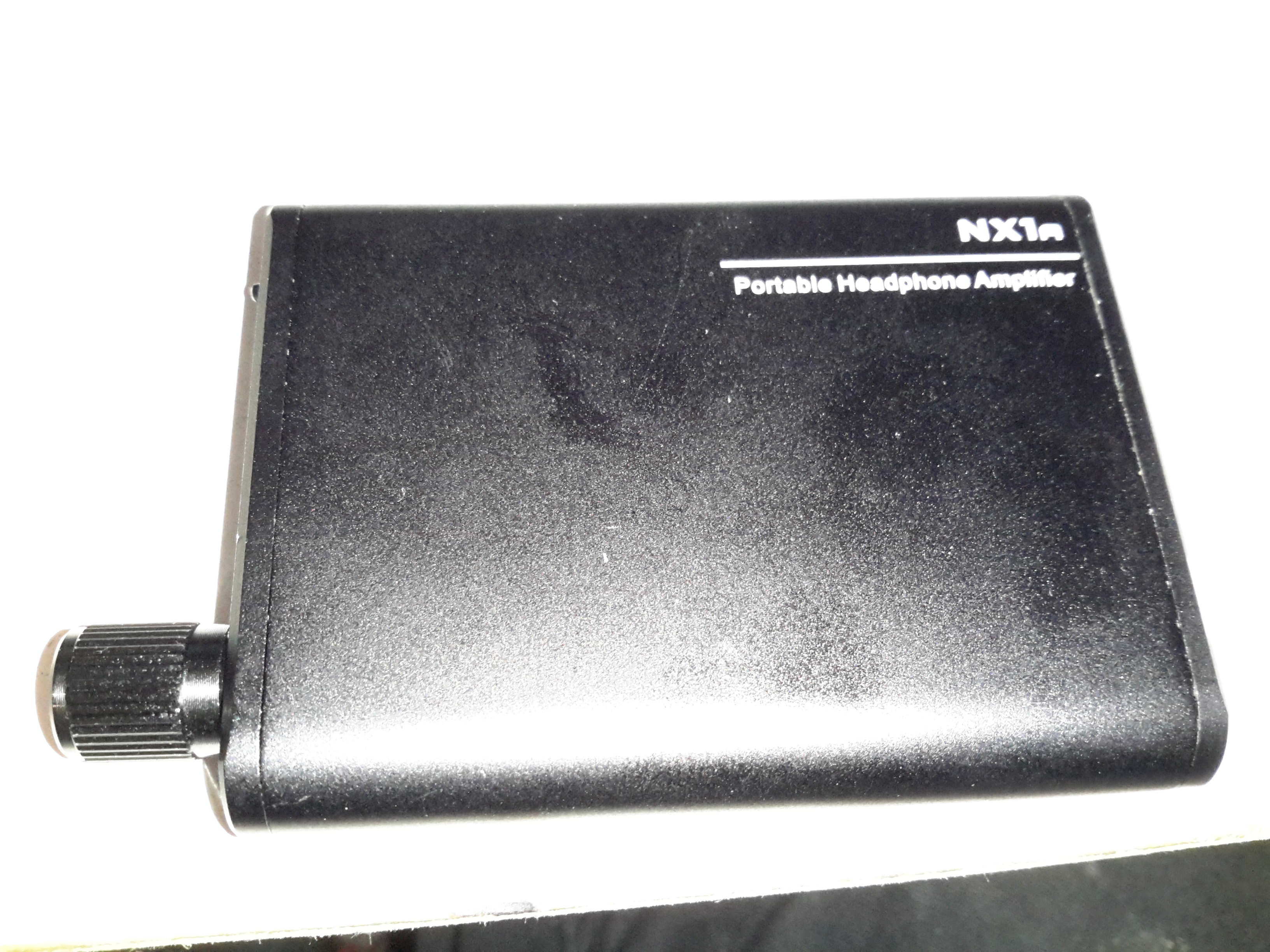
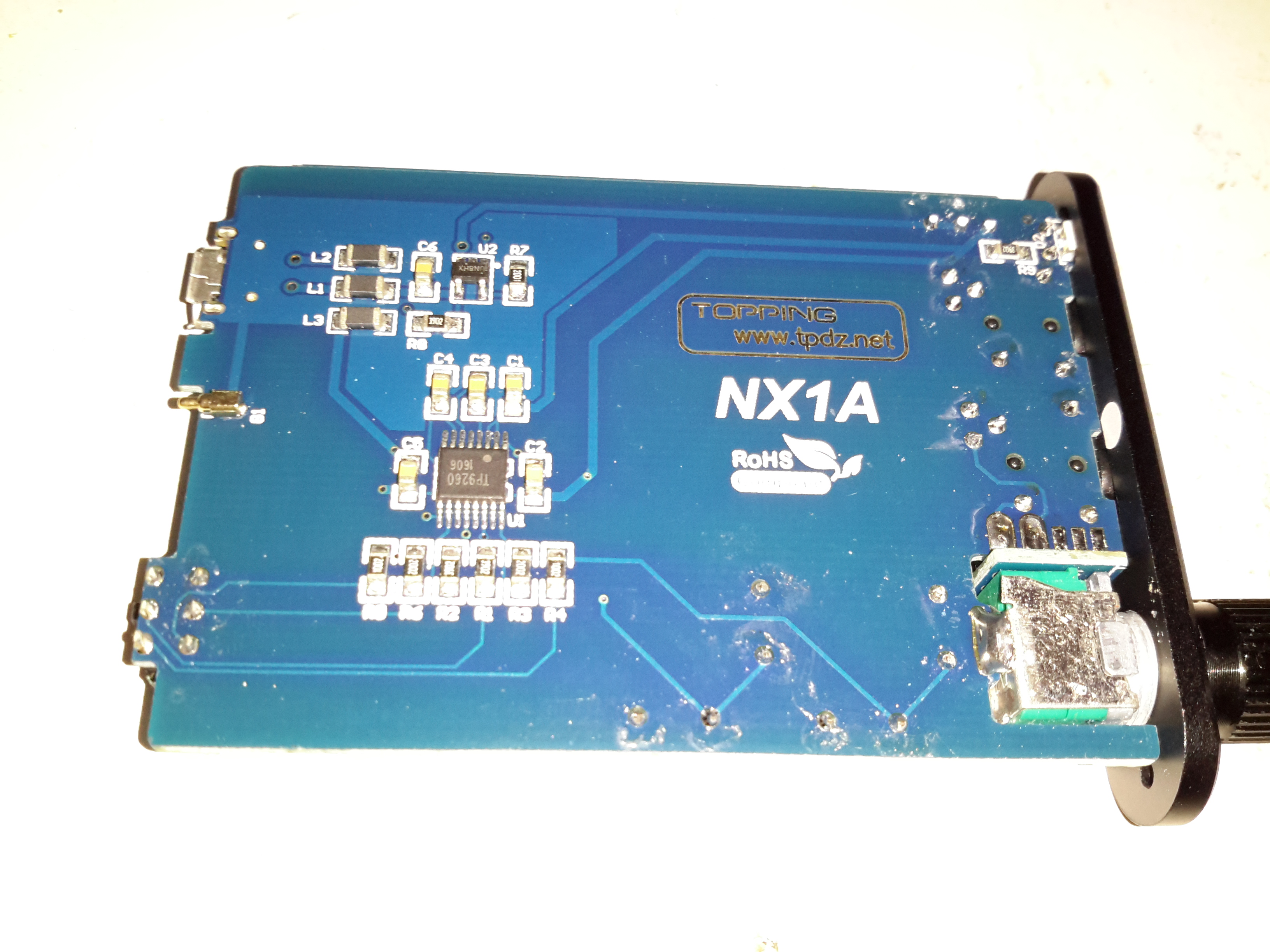
Time for another teardown! Here’s a pocket-sized headphone amplifier for use with mobile devices. This unit is powered by a built-in lithium cell, and can give some pretty impressive volume levels given it’s small size.
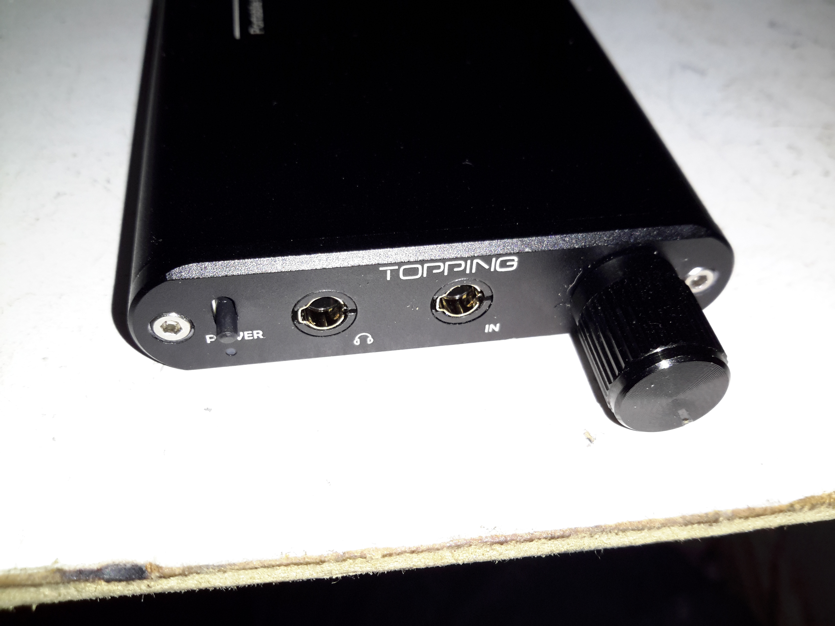
Audio Connections
The 3.5mm audio input & output jacks are on the front of the unit, along with the relatively enormous volume knob & power switch. There’s a little blue LED under the switch that lets the user know when the power is on, but this is a very sedate LED, using very little power.
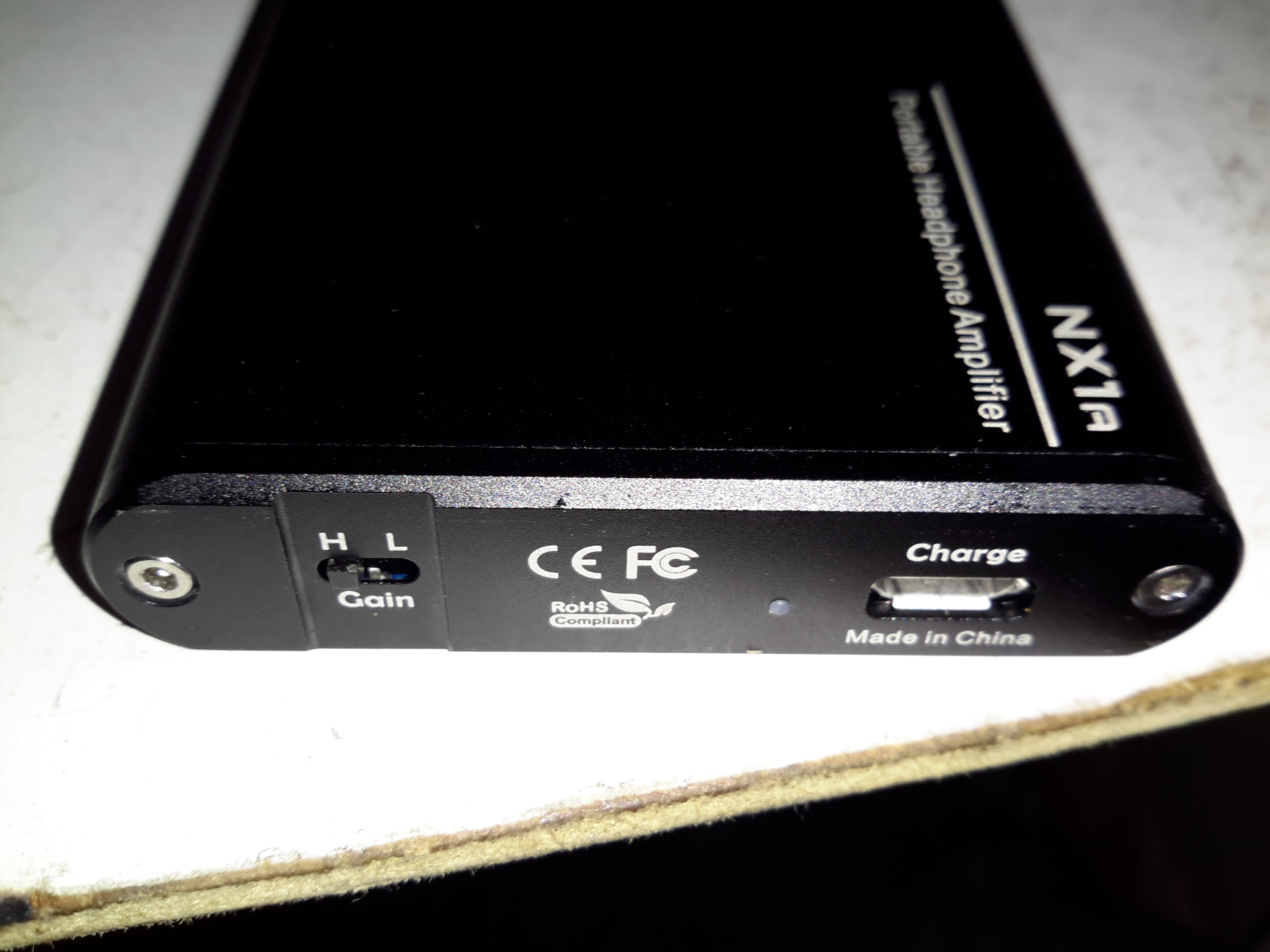
Gain & Charging
On the back is the High-Low gain switch, and the µUSB charging port. There’s another indicator LED to show that the internal cell is charging, in this case a red one.
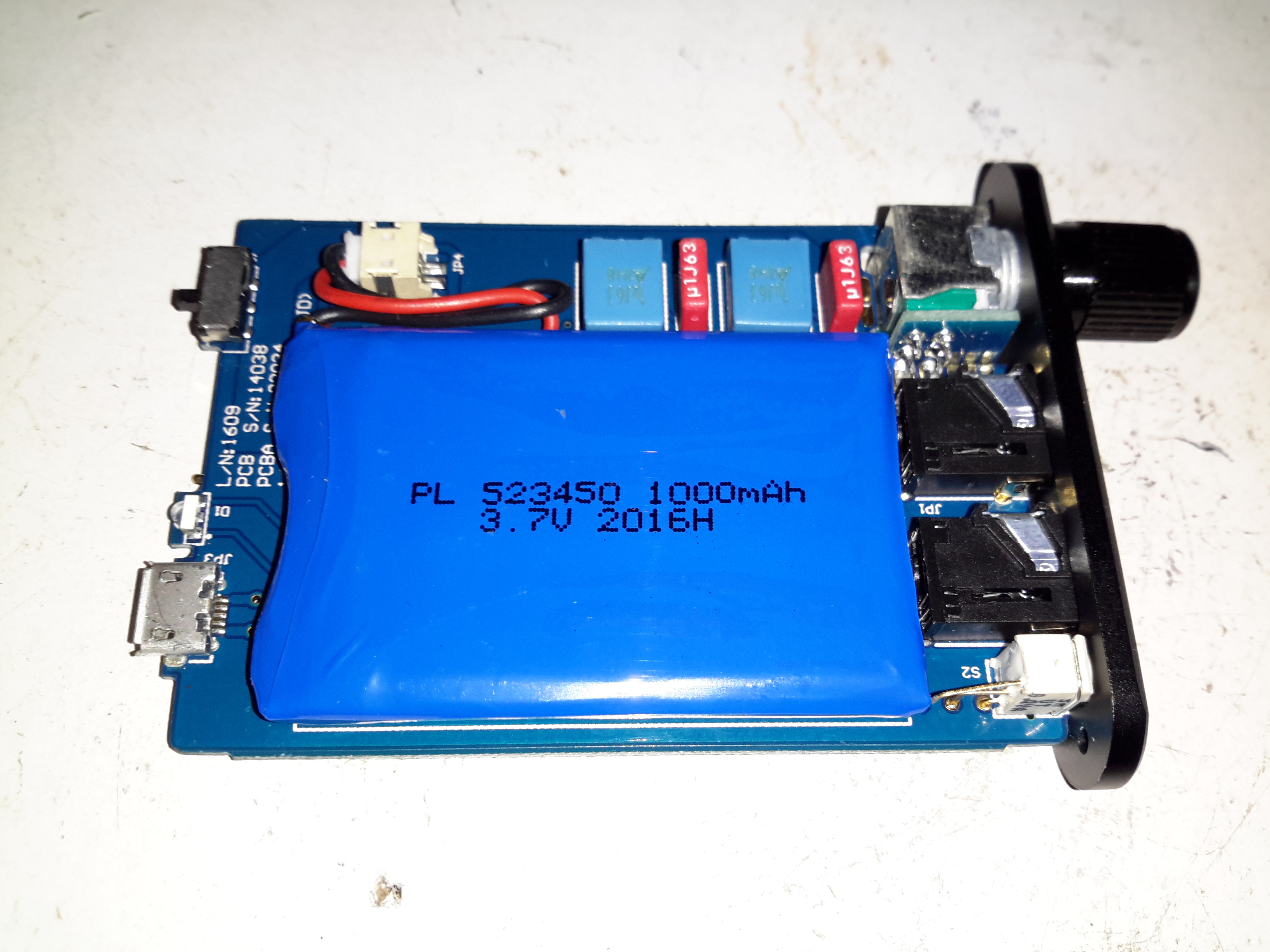
PCB Top
Removing a couple of cap screws allows the internals to slide out of the extruded aluminium casing. Most of the internal space is taken up by the 1Ah lithium cell, here on the top of the PCB secured by some double-sided tape. The volume potentiometer is mounted on a small daughterboard at right angles to get it to fit into the small vertical space in the case.
PCB Rear
The bottom of the PCB is equally as sparse – the only ICs being the main audio amp in the centre & the battery charger IC at the top.
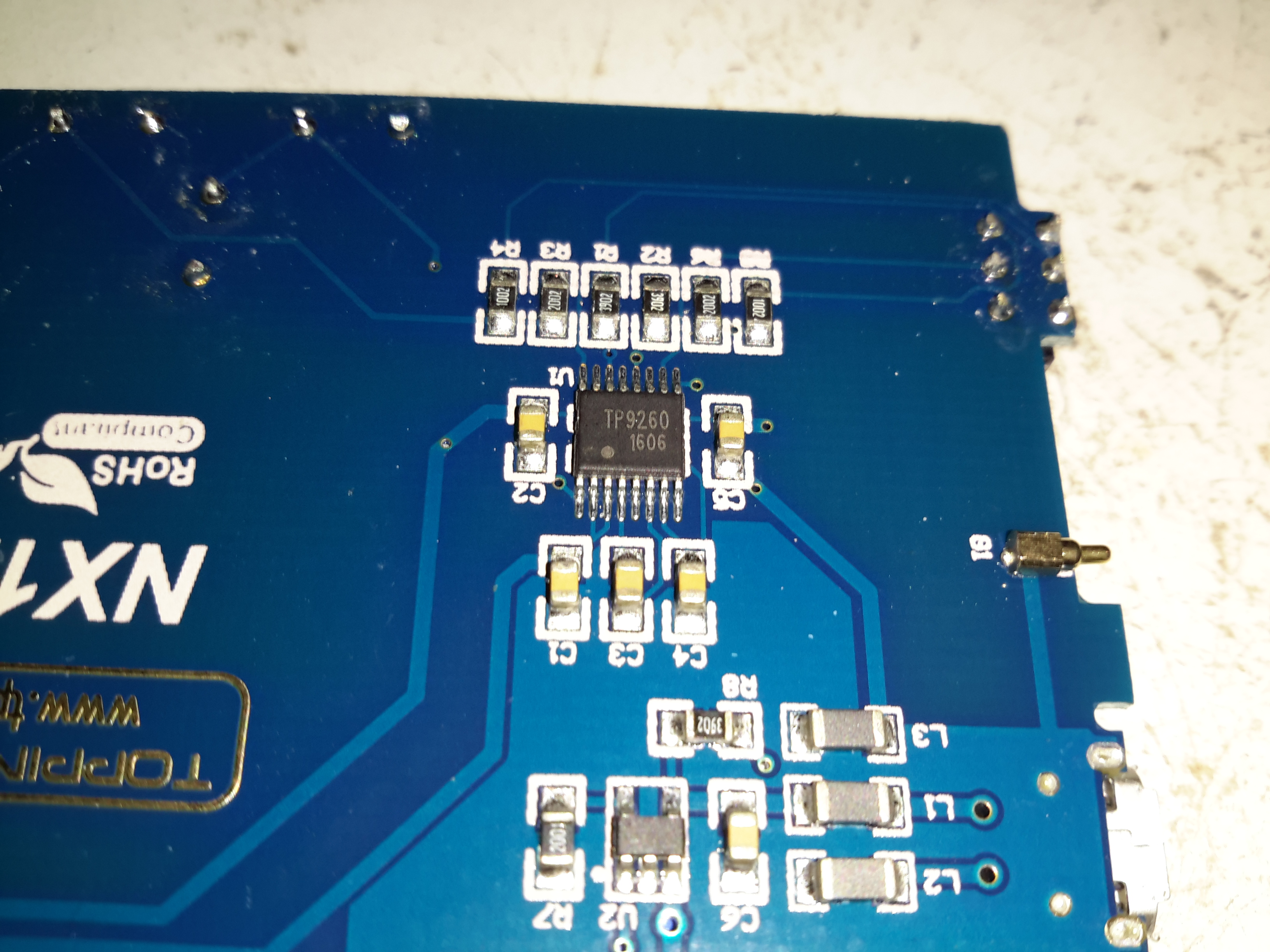
Amplifier IC
The main audio amplifier is a TP9260, I couldn’t find a datasheet on this, so I’m unsure of what the specs are. The row of resistors above the IC are for the gain divider circuit. There’s also a pogo pin on the right that makes contact with the back panel of the case for grounding.
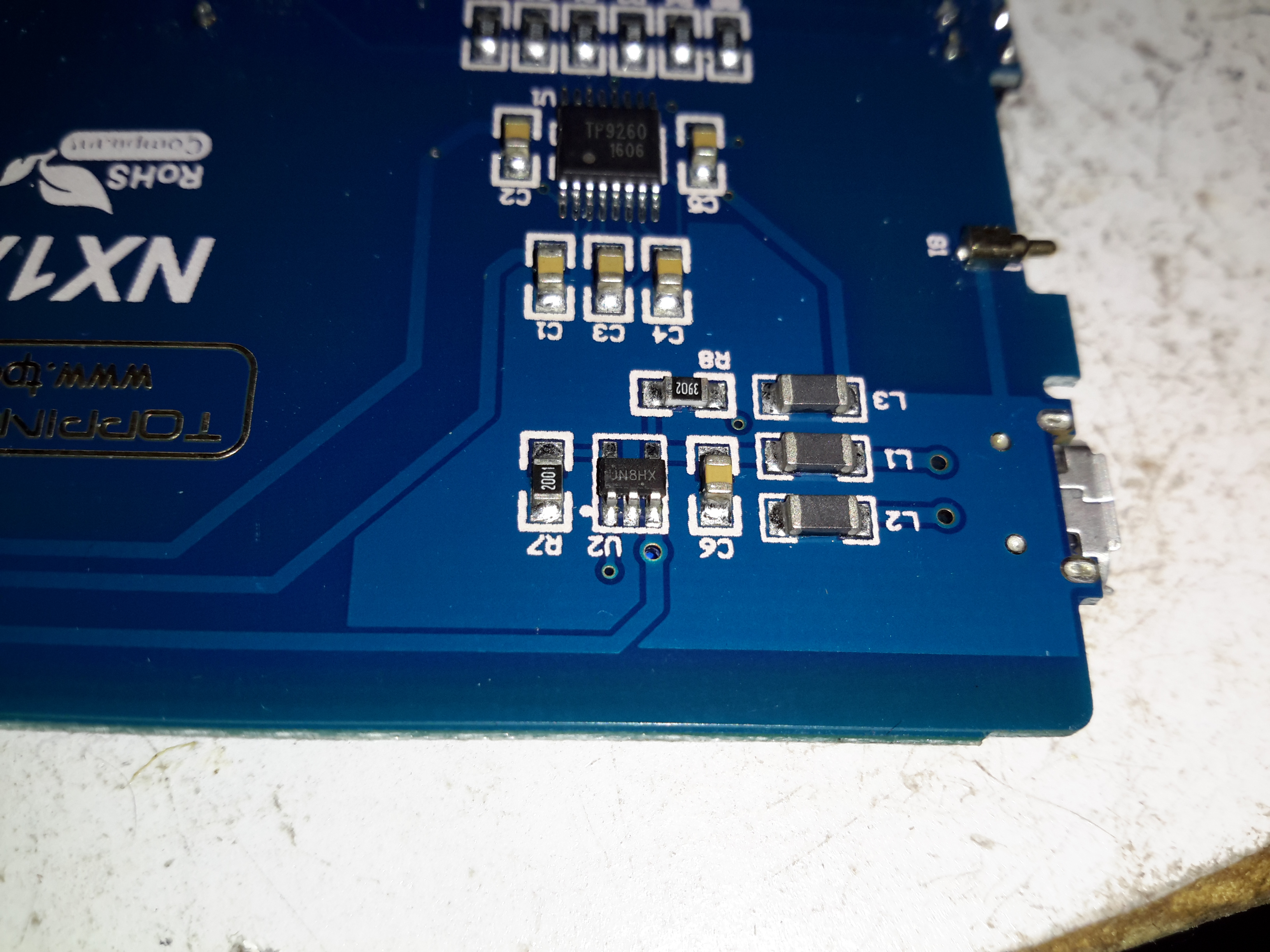
Battery Charger
Battery charging is taken care of by a UN8HX 500mA linear charging IC, not much special here.
This little amplifier seems to be pretty well made, considering the price point. The only issue I’ve had so far is the audio cables act like antennas, and when in close proximity to a phone some signal gets picked up & blasted into the headphones as interference.
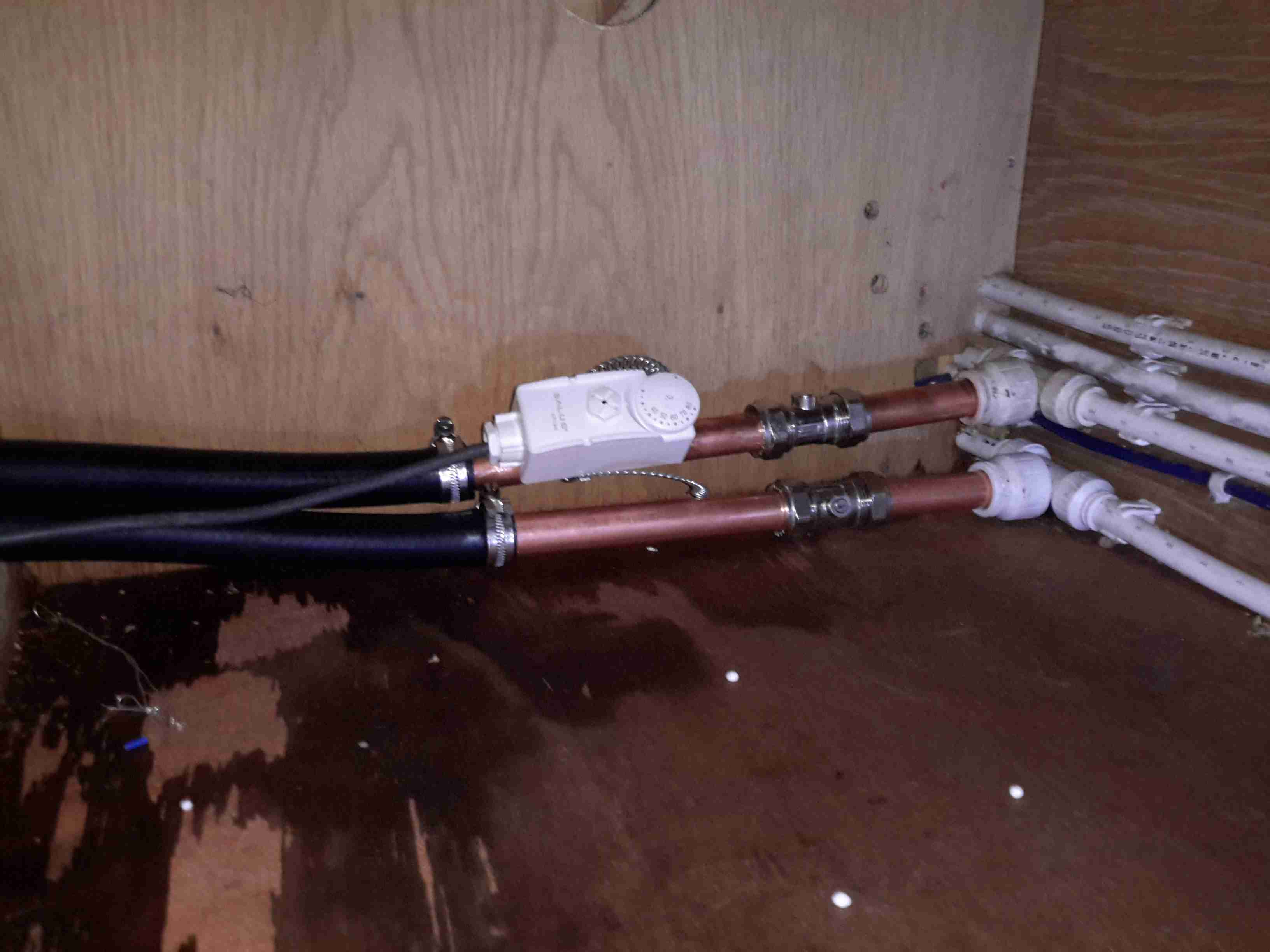
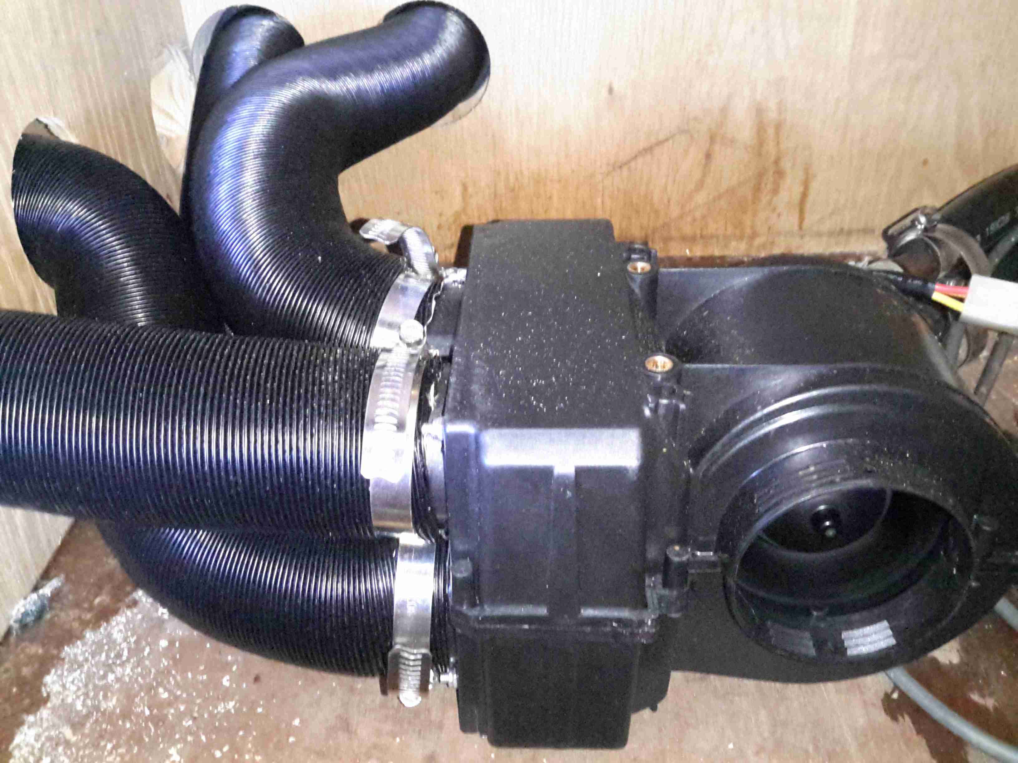
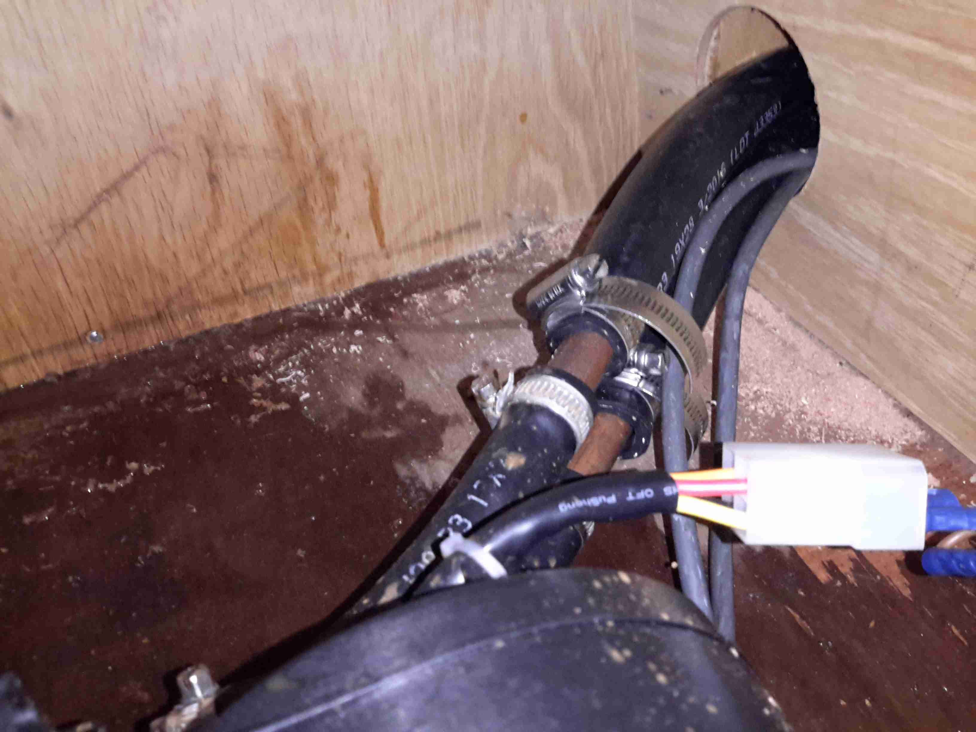
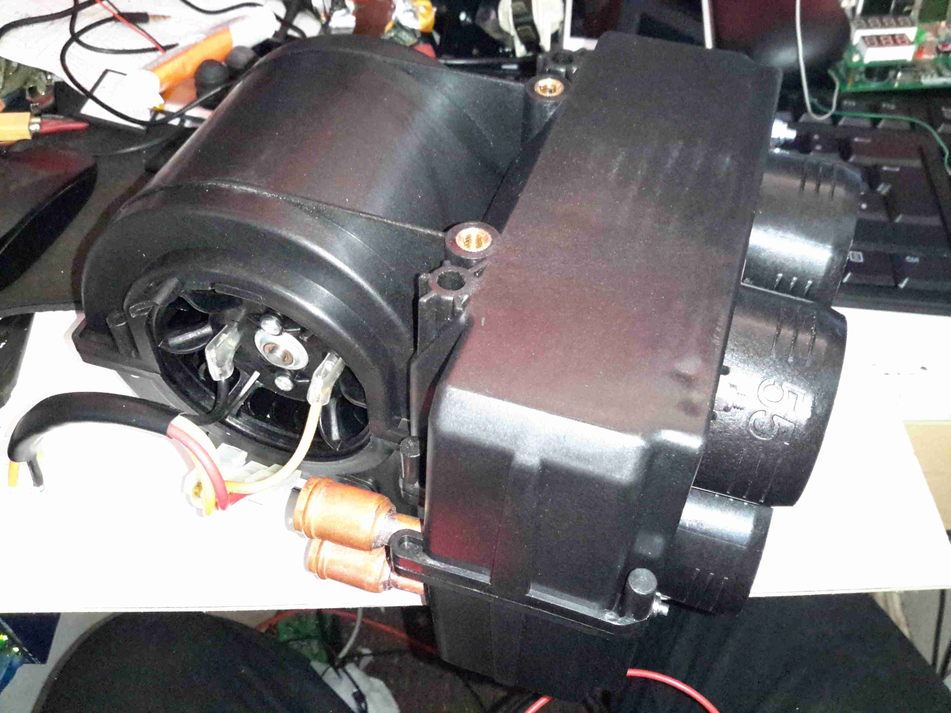
Here the pipework feeding the matrix of the blower unit has been tapped into the heating circuit, the first radiator on the loop is just out of shot to the right, this is all tucked away under the bed in one of the cabins. The pipestat is attached to the flow from the boiler, this will switch on the blower once hot water starts flowing through the system. Isolation valves have been fitted to make the inevitable maintenance of the matrix unit easier, as the system is pressurised to 14PSI, dropping the pressure out of the system without making quite a mess is difficult.
Heater Matrix & Ducting
The heater itself is mounted on the other side of a wooden partition in the small space left under a shelf. This made installing the unit like trying to plumb in a radiator through a letterbox ;). 4 60mm ducts snake off to the vents mounted in the wall.
Water Connections
The hot water hoses appear through a hole in the timber to connect to the matrix unit, with some 15mm pipe in between as reducers from the 3/4″ hose to the 1/2″ attached to the matrix itself. The blower is wired in low speed mode only, as running it any faster makes far too much noise from the vents.
As a heating solution, this unit works well onboard. Within a 10 minutes of the diesel heater firing up, the blower automatically comes on thanks to the thermostat, and blows plenty of hot air into the saloon to keep the cold at bay.
Here’s an eBay oddity – it’s got the same light & lens mechanism as the cheap “disco light” style bulbs on eBay, but this one is battery powered & has a built in MP3 player.
MP3 Disco Light
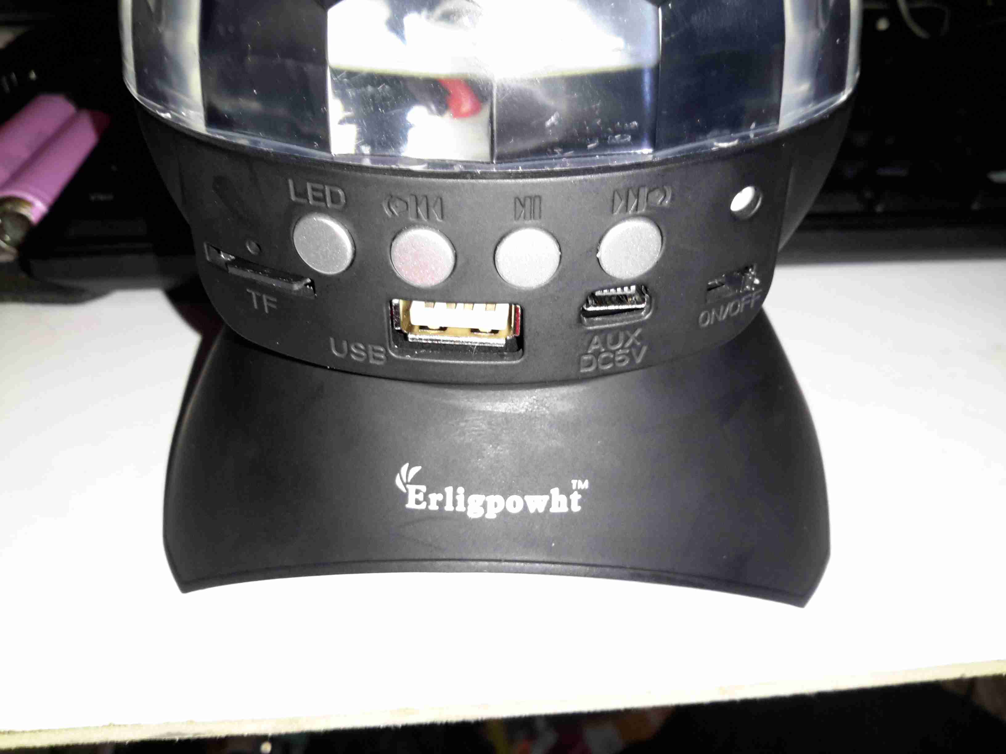
This device simply oozes cheapness. The large 4″ plastic dome lens sits on the top above the cheap plastic moulding as a base, which also contains the MP3 player speaker.
Controls
There are few controls on this player, the volume buttons are combined with the skip track buttons, a long press operates the volume control, while a short press skips the tracks. Several options for getting this thing to play music are provided:
Bluetooth – Allows connection from any device for bluetooth audio
USB – Plugging in a USB flash drive with MP3 files
SD Card – Very similar to the USB flash drive option, just a FAT32 formatted card with MP3 files
Aux – There’s no 3.5mm jack on this unit for an audio input, instead a “special” USB cable is supplied that is both used to charge the built in battery & feed an audio signal. This is possible since the data lines on the port aren’t used. But it’s certainly out of the ordinary.
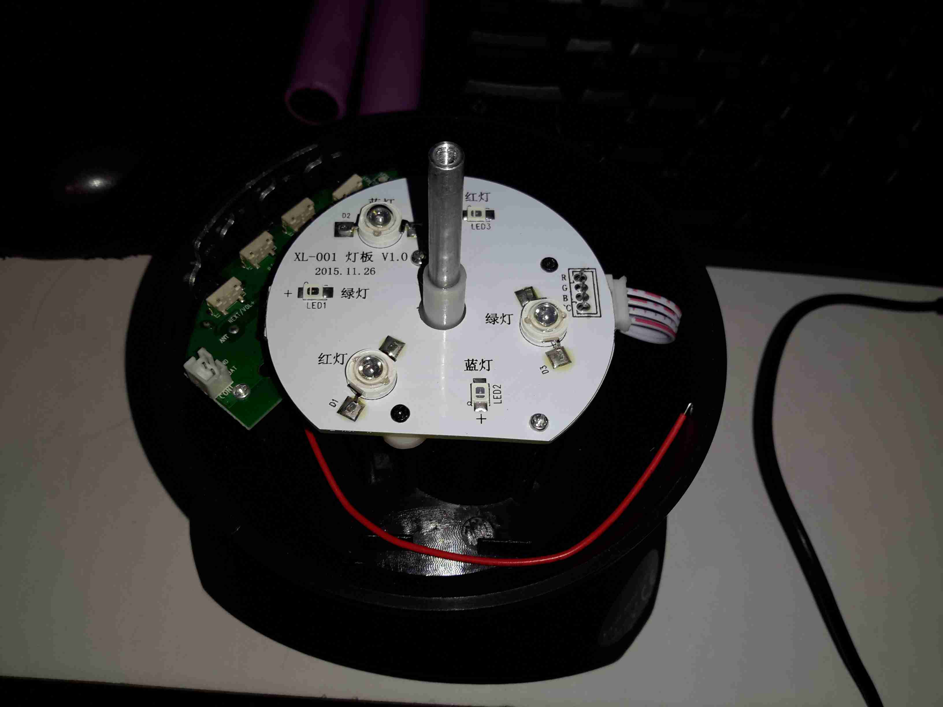
Top Removed
The top comes off with the removal of a single screw in the centre of the lens. The shaft in the centre that holds the lens is attached to a small gear motor under the LED PCB. There’s 6 LEDs on the board, to form an RGB array. Surprisingly for a very small battery powered unit these are bright to the point of being utterly offensive.
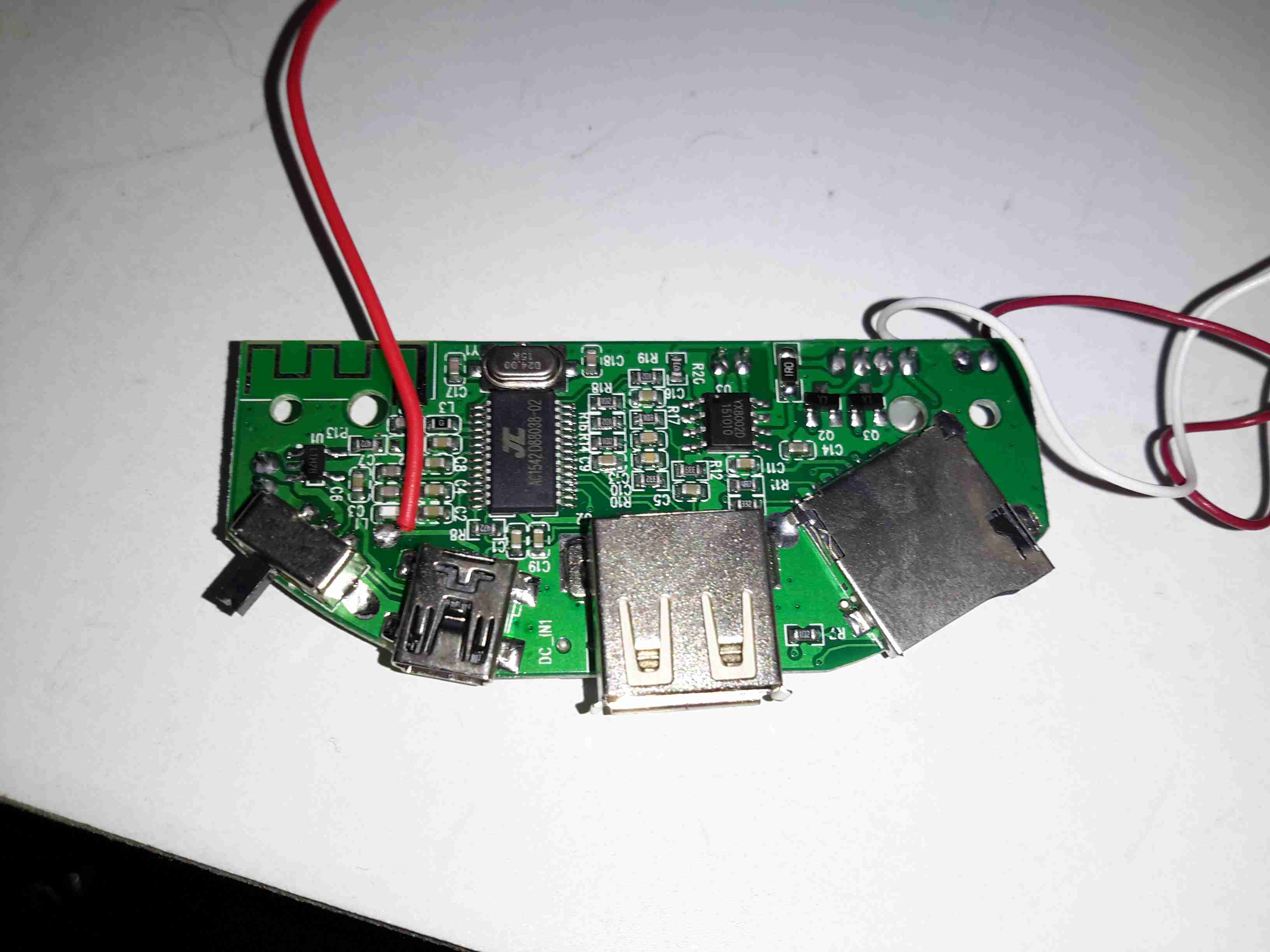
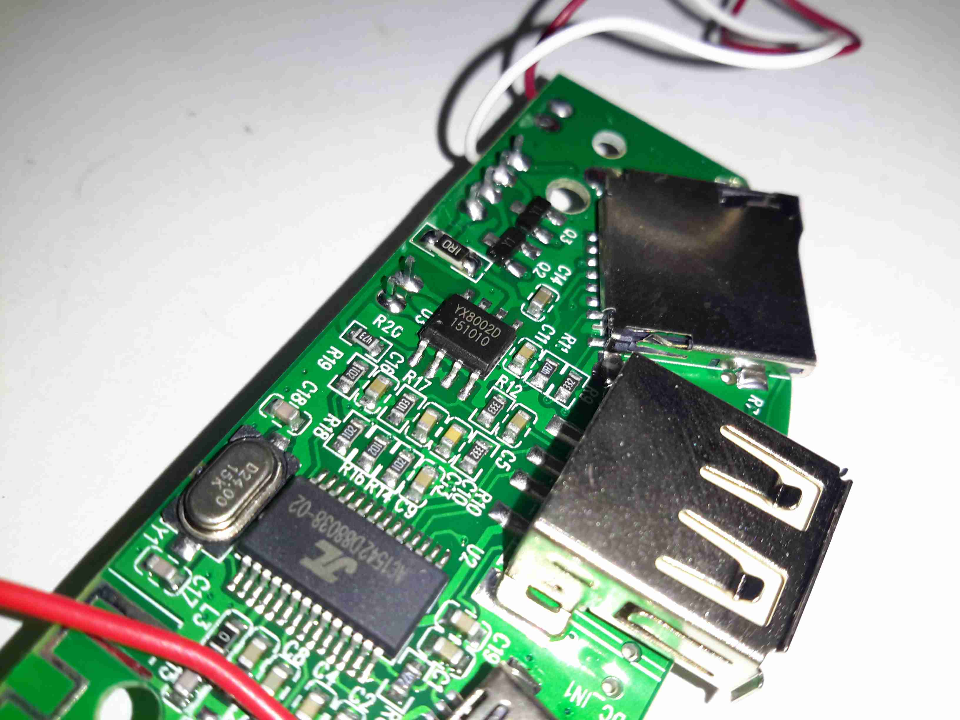
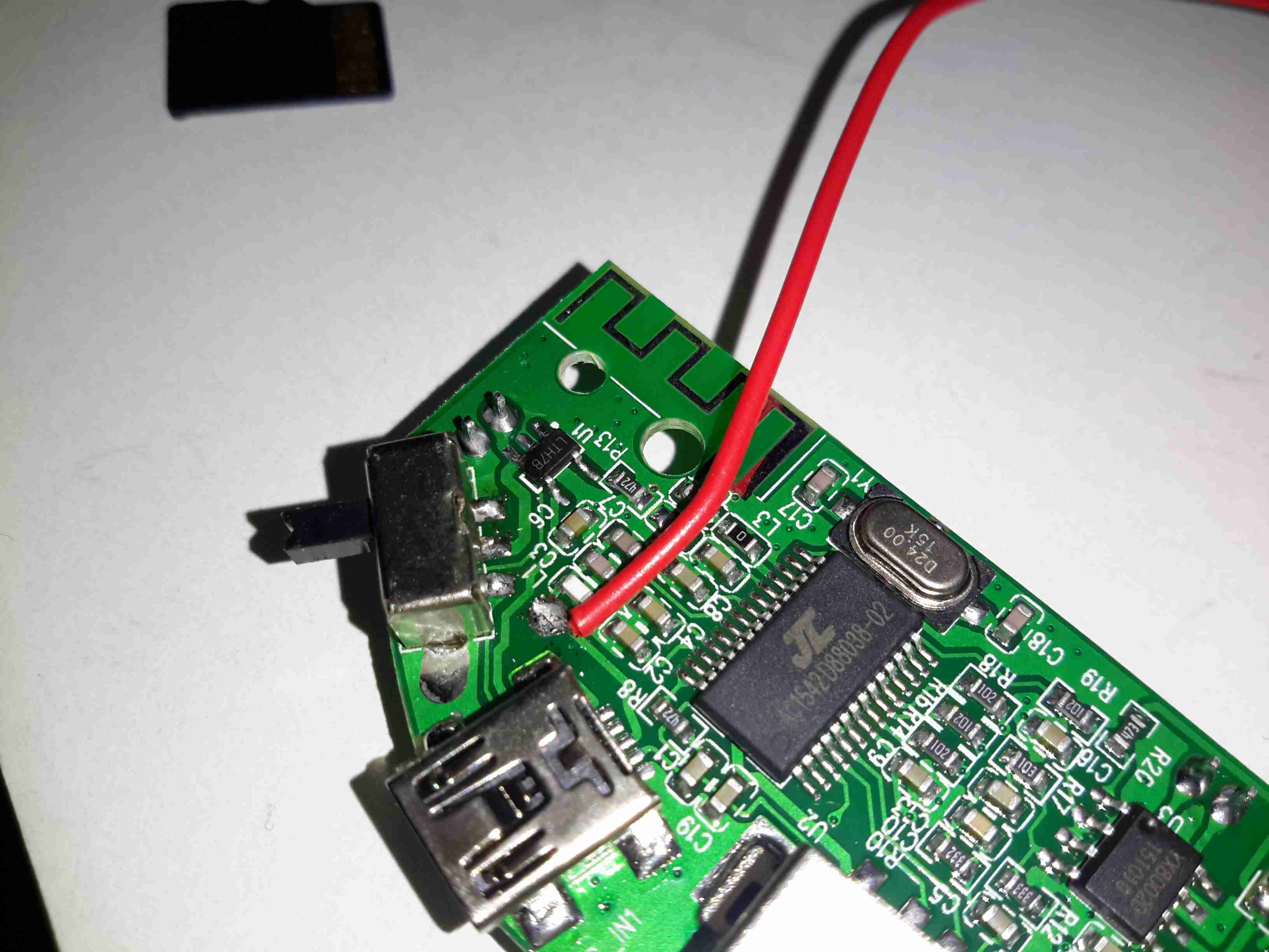
Mainboard
Here’s the mainboard removed from the plastic base. There’s not much to this device, even with all the options it has. The power switch is on the left, followed by the Mini-B USB charging port & aux audio input. The USB A port for a flash drive is next, finishing with the µSD slot. I’m not sure what the red wire is for on the left, it connects to one of the pins on the USB port & then goes nowhere.
Audio Amplifier
The audio amplifier is a YX8002D, I couldn’t find a datasheet for this, but it’s probably Class D.
Main Chipset
Finally there’s the main IC, which is an AC1542D88038. I’ve not been able to find any data on this part either, it’s either a dedicated MP3 player with Bluetooth radio built in, or an MCU of some kind.The RF antenna for the Bluetooth mode is at the top of the board.
Just behind the power switch is a SOT23-6 component, which should be the charger for the built in Lithium Ion cell.
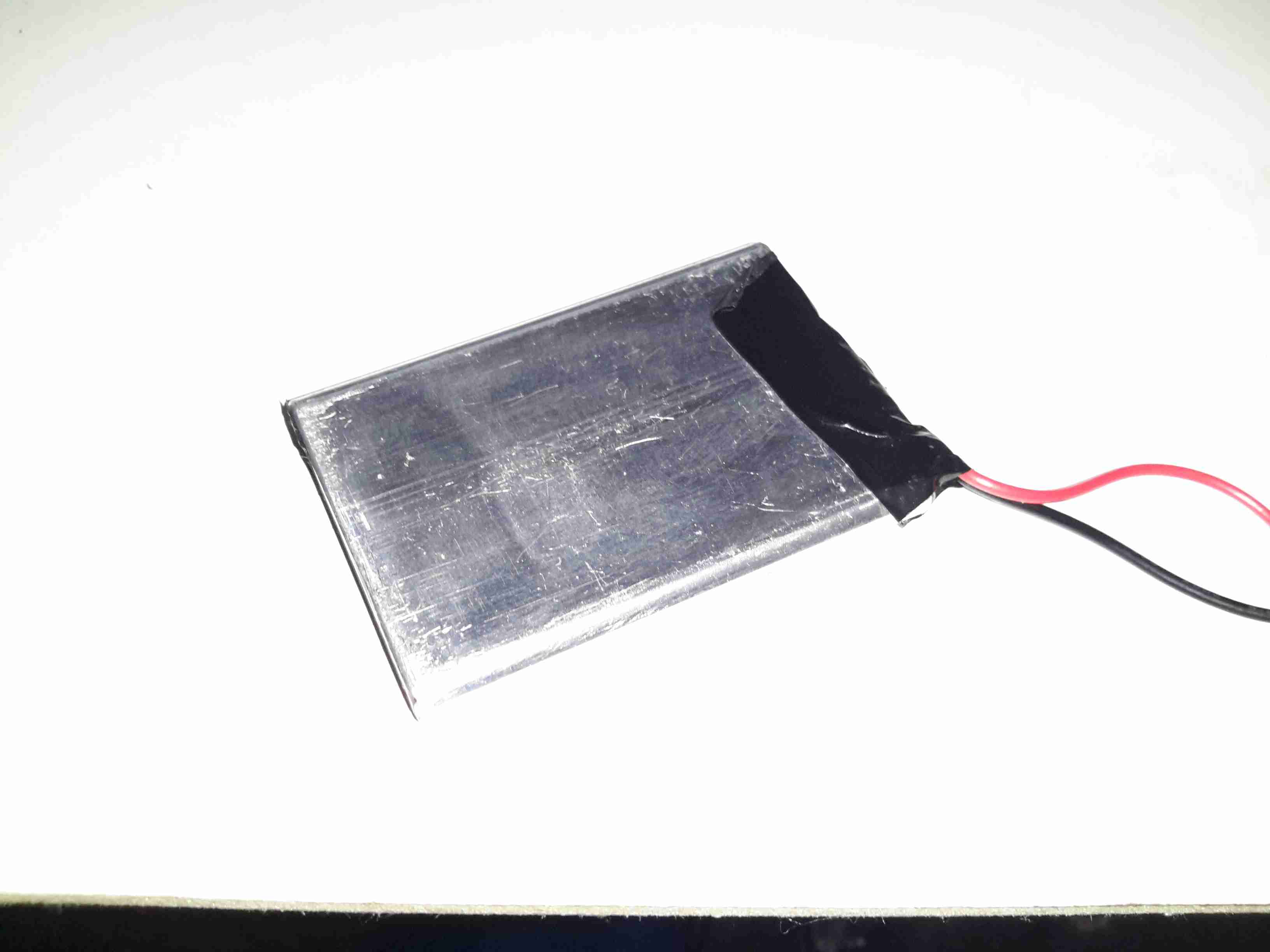
Lithium Ion Cell
The cell itself is a prismatic type rated in the instructions at 600mAh, however my 1C discharge test gave a reading of 820mAh, which is unusual for anything Li-Ion based that comes from eBay 😉
There is cell protection provided, it’s under the black tape on the end, nothing special here.
The main issue so far with this little player is the utterly abysmal battery life – at full volume playing MP3s from a SD card, the unit’s current draw is 600mA, with the seizure & blindness-inducing LEDs added on top, the draw goes up to about 1200mA. The built in charger is also not able to keep up with running the player while charging. This in all only gives a battery life of about 20 minutes, which really limits the usability of the player.
With the installation of the new diesel fired heater we’ve noticed a small problem – since the only heat source in the saloon is the stove, even with the diesel heater fired up the temperature doesn’t really change much, as the heat from the radiators in the both the cabins & the head isn’t spreading far enough.
The solution to this problem is obviously an extra radiator in the saloon, however there isn’t the space to fit even a small domestic-style radiator. eBay turned up some heater matrix units designed for kit cars & the like:
3.8kW Matrix
These small heater matrix units are nice & compact, so will fit into the back of a storage cupboard next to the saloon. Rated at a max heat output of 3.8kW, just shy of the stove’s rated 4kW output power, this should provide plenty of heating when we’re running the diesel heater rather than the fire.
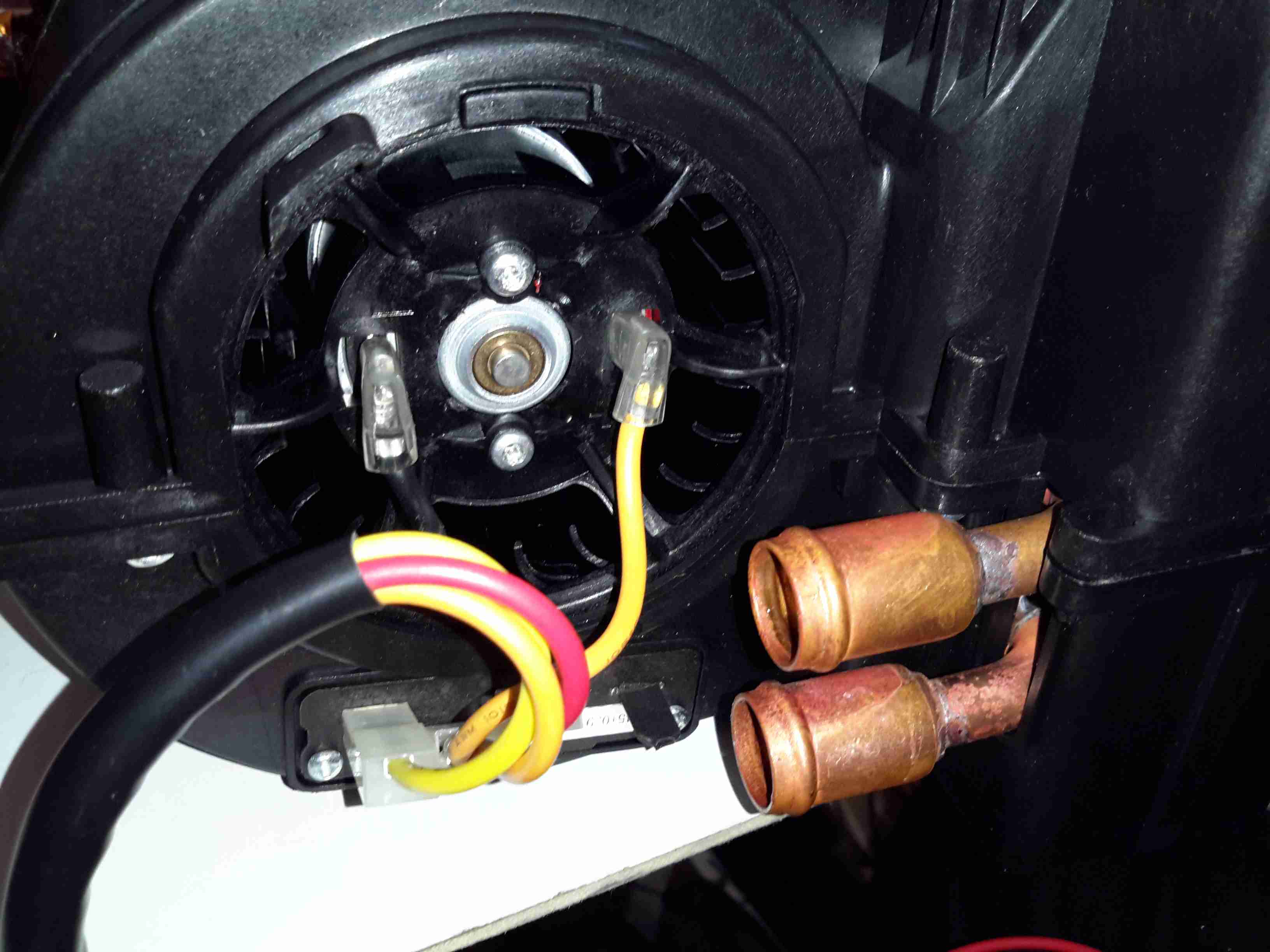
Water & Power
The blower motor has a resistor network to provide 3 speeds, but this probably won’t be used in this install, water connections are via 15mm copper tails. The current plan is to use a pipe thermostat on the flow from the boiler to switch on the blower when the water temperature reaches about 40°C.
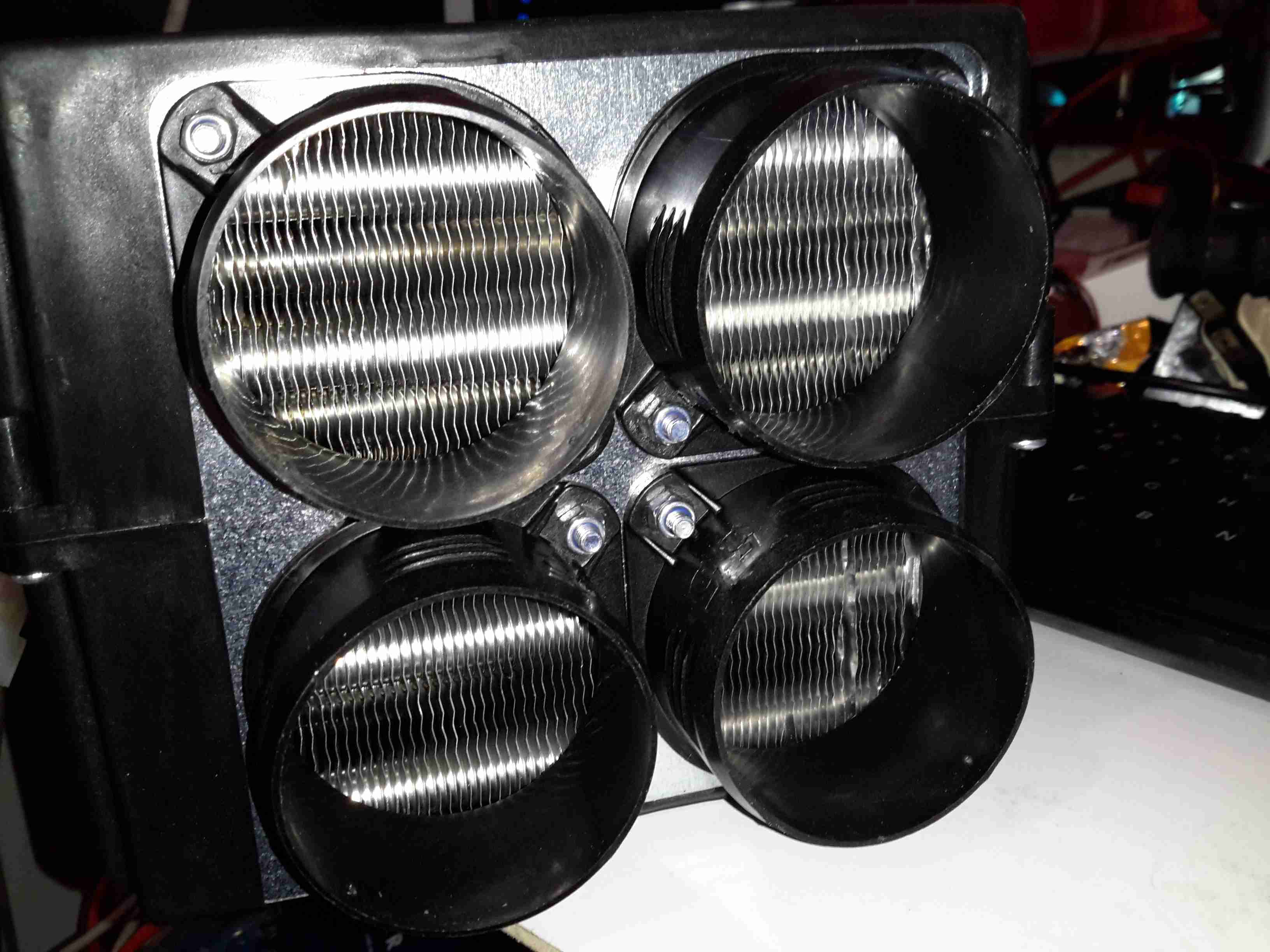
Hot Air Outlets
The hot air emerges from the matrix via 4 55mm duct sockets. This gives enough outlets to cover both the saloon & the corridor down to the cabins.
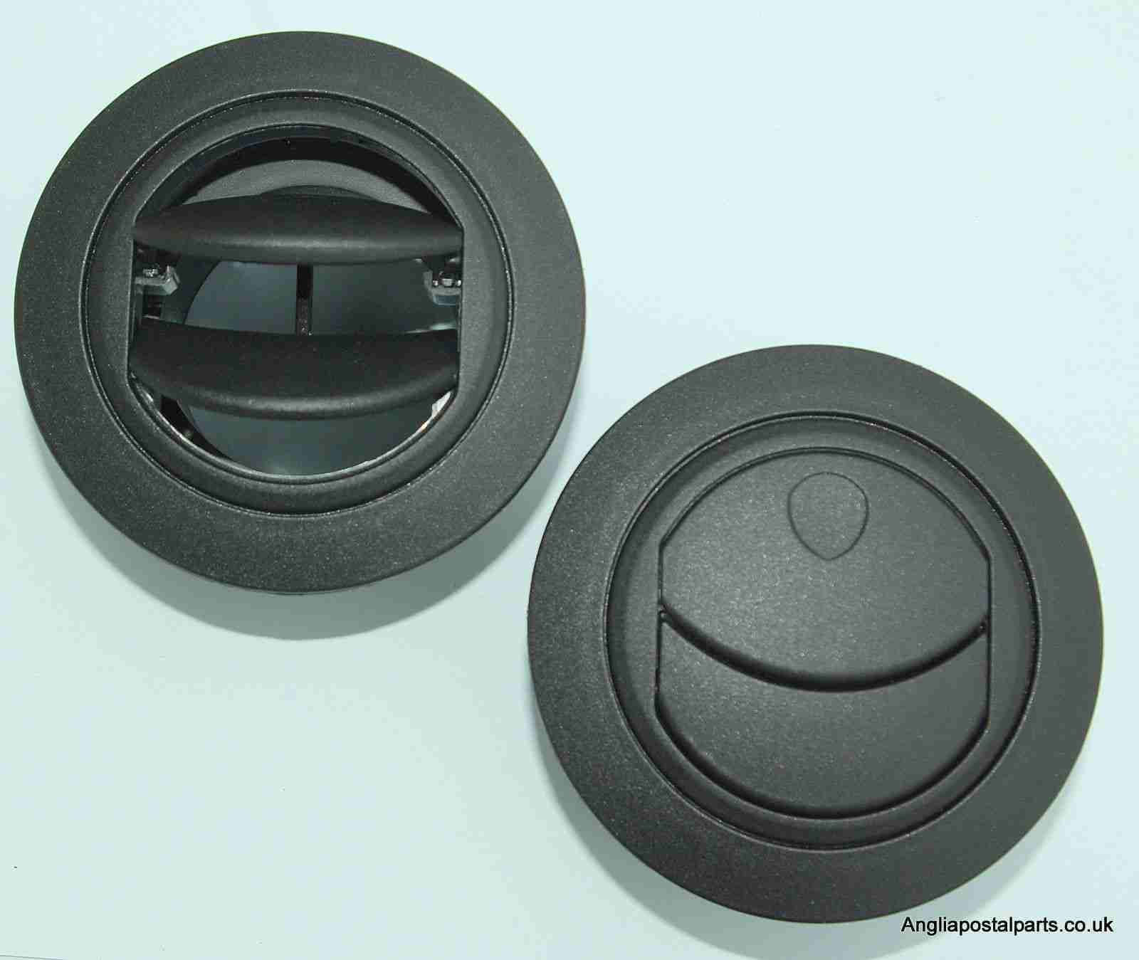
Hot Air Vents
Standard 60mm Eberspacher style vents will be used to point the warmth where it’s needed.
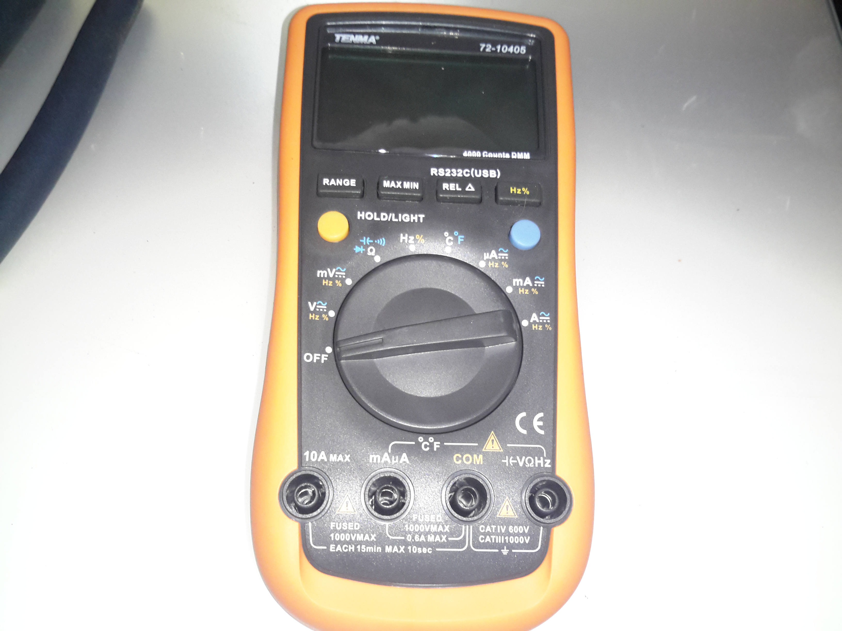
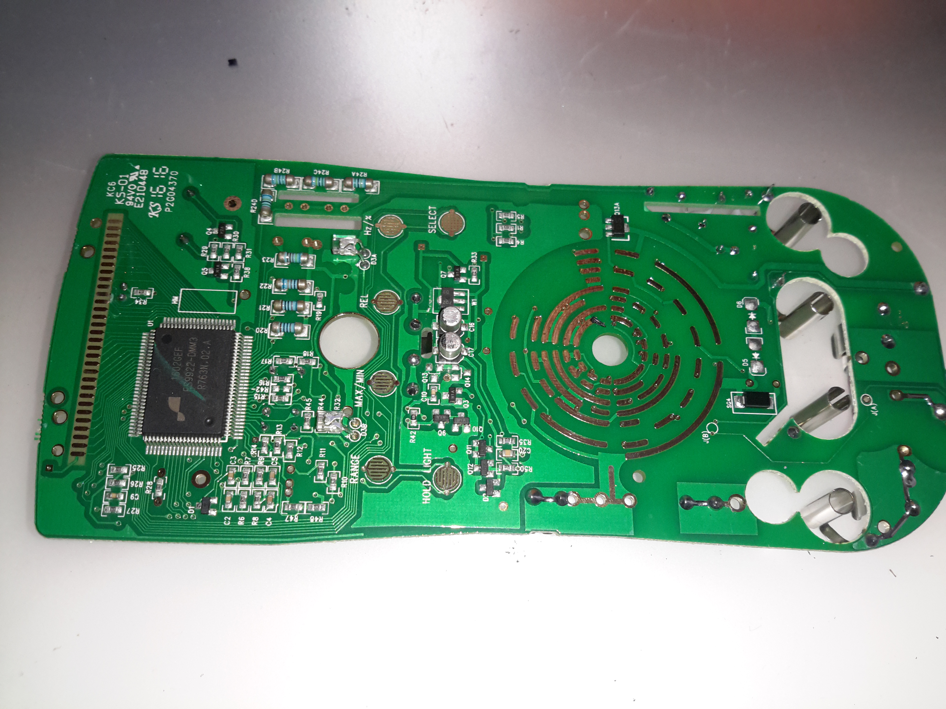
Well it’s time for a new DMM. After the last pair of eBay El-Cheapo Chinese meters just didn’t last very well, I decided a proper meter was required. This one is a Tenma 72-10405, stocked by Farnell for under £60. Not quite as many festures as the cheapo Chinese meters, but I expect this one to be a bit more reliable.
PCB Rear
Since I can’t have anything without seeing how it’s put together, here’s the inside of the DMM. (Fuse access is only possible by taking the back cover off as well. The 9v PP3 battery has a seperate cover).
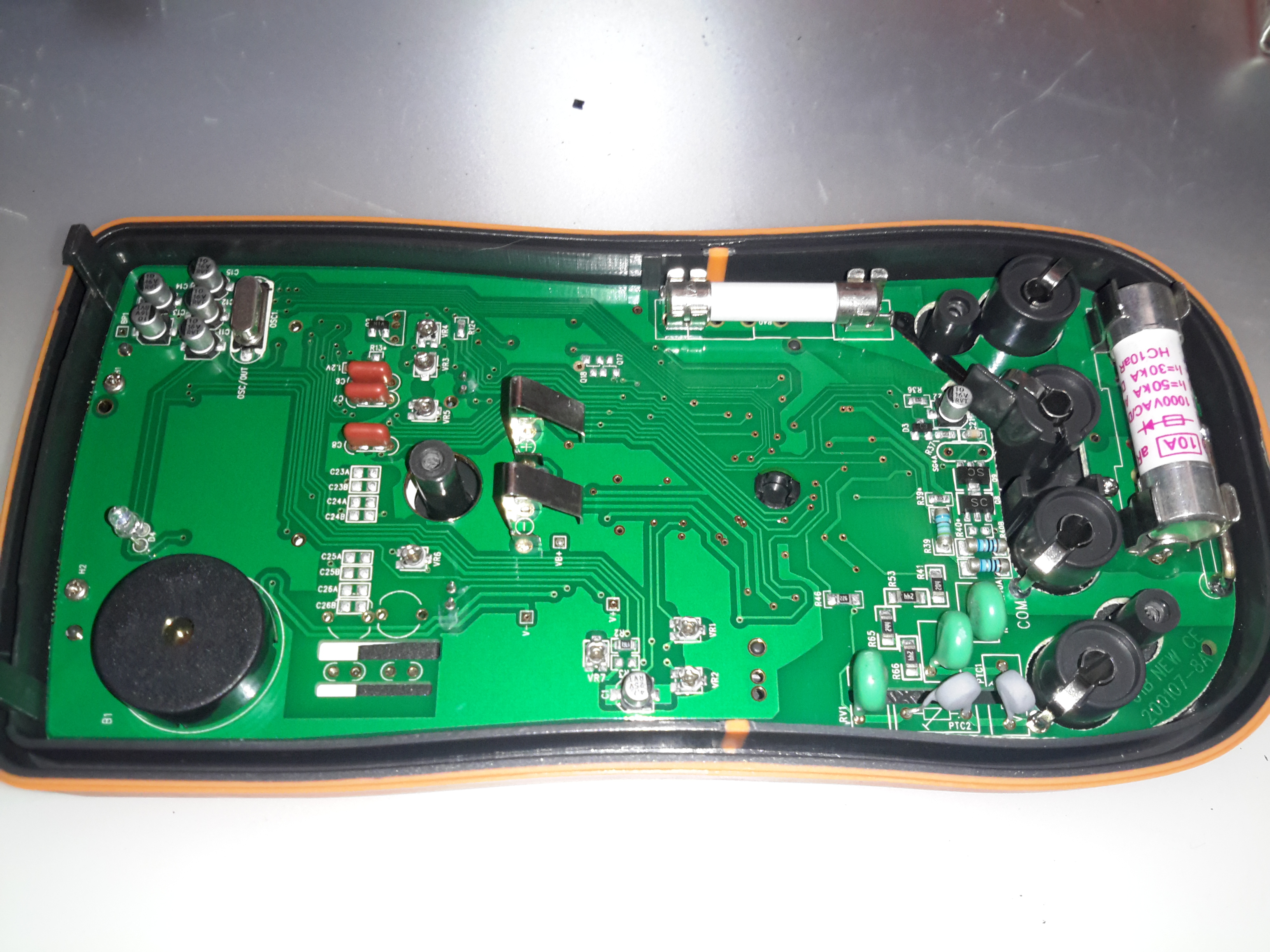
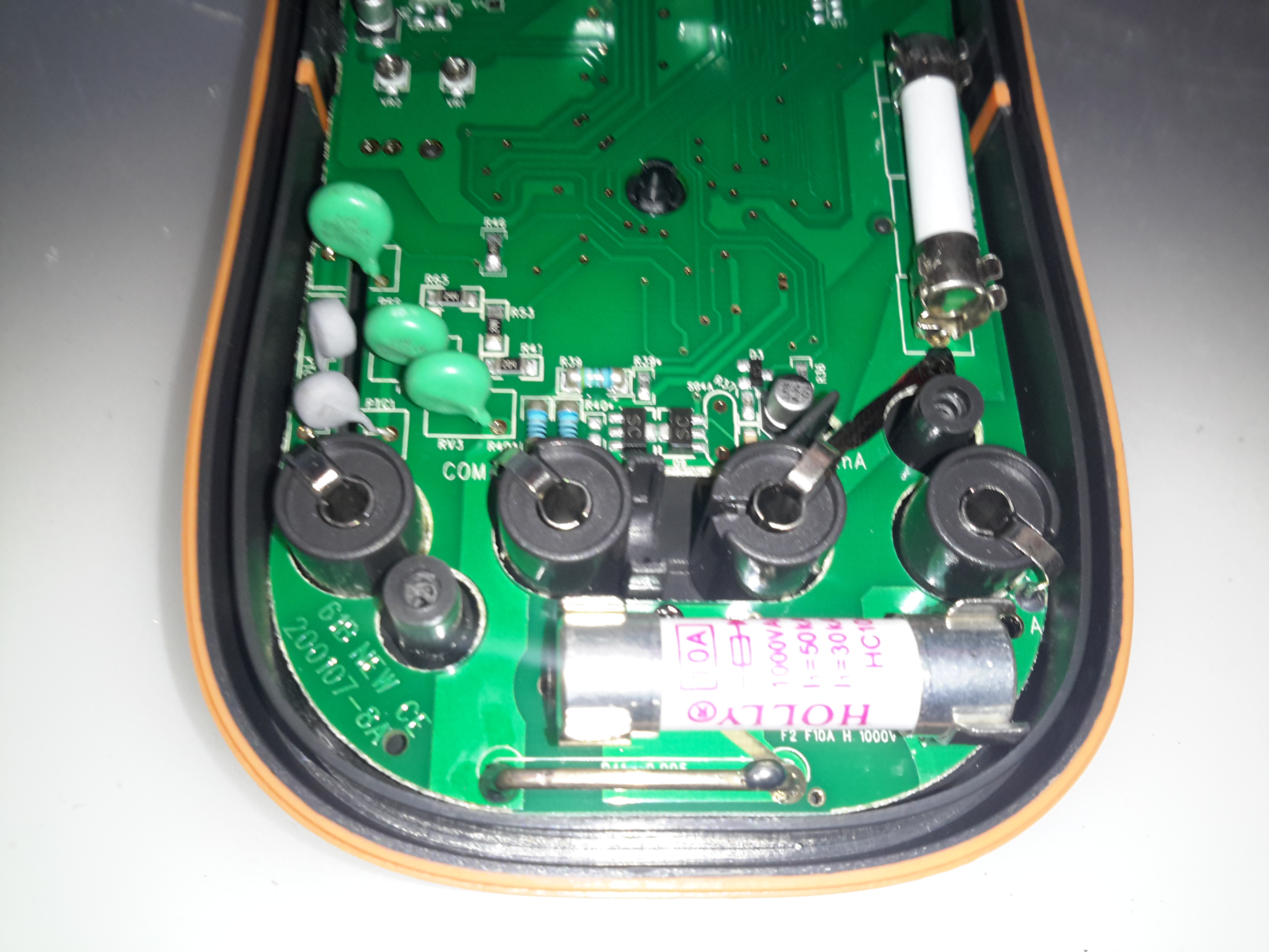
PCB Rear Bottom
He’s the input section of the meter, with the 10A HRC fuse & current shunt for the high-amps range. The other fuse above is for the mA/µA ranges. The back cover has a wide lip around the edge, that slots into a recess in the front cover, presumably for blast protection if the meter should meet a sticky end. The HRC fuses are a definite improvement over the cheap DMMs, they only have 15mm glass fuses, and no blast protection built into the casing.
There are some MOVs for input protection on the volts/ohms jack, the jacks themselves are nothing more than stampings though.
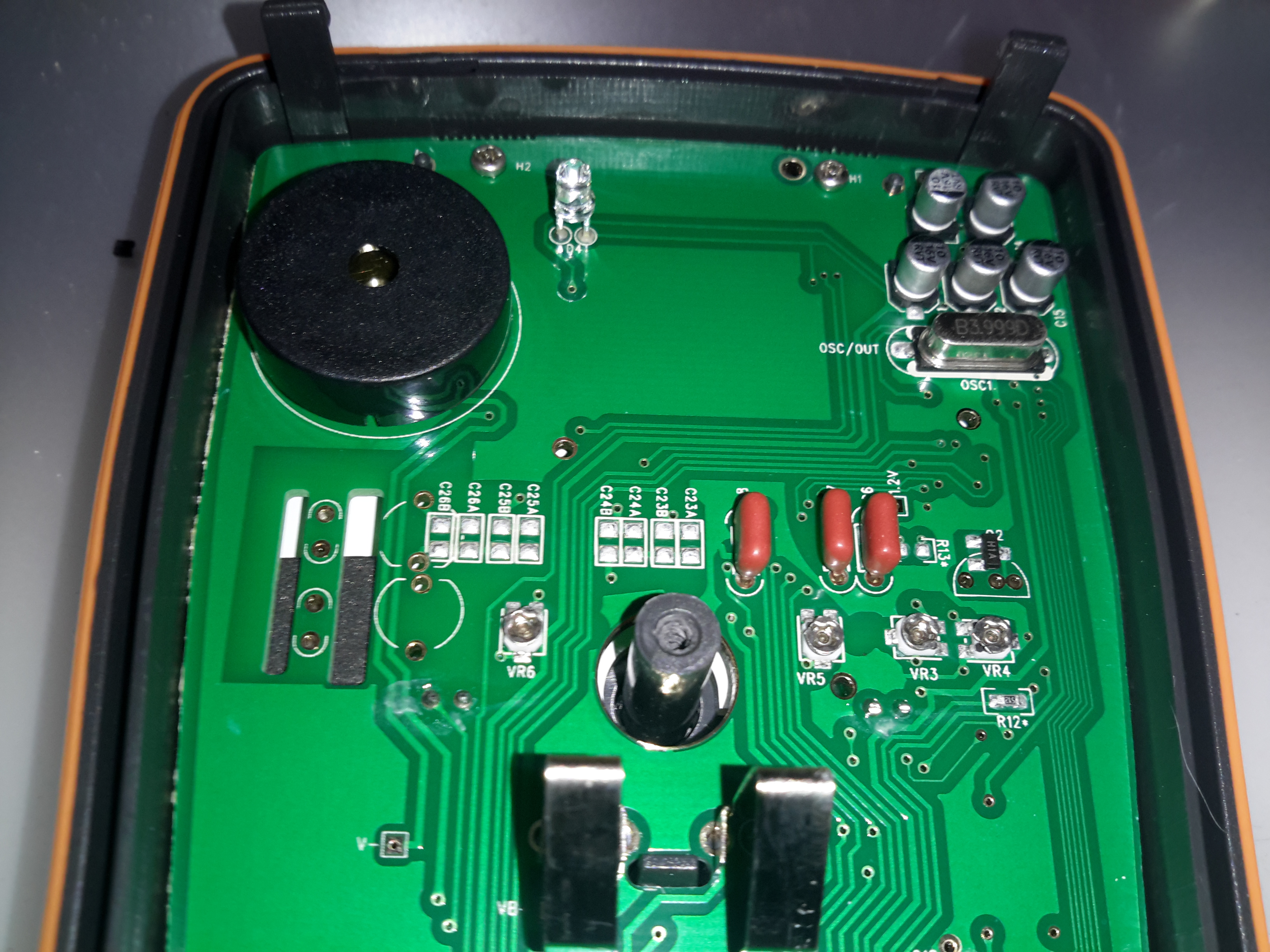
PCB Rear Top
Not much at the other side of the board, there’s the IR LED for the RS232 interface & the beeper.
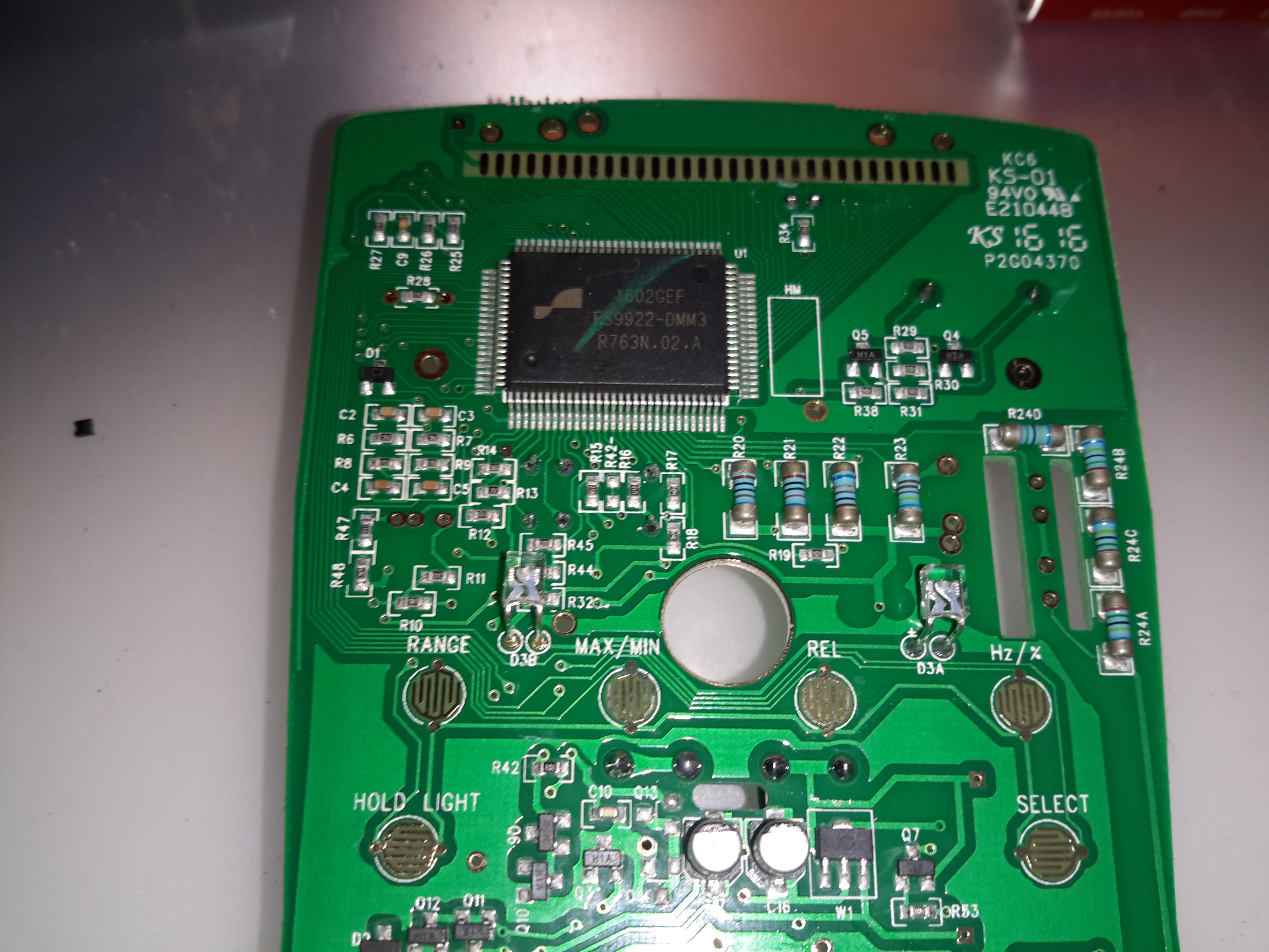
PCB Front
Most of the other components are on the other side of the PCB under the LCD display. The range switch is in the centre, while the main chipset is on the left.
DMM Chipset
The chipset of this meter is a FS9922-DMM3 from Fortune Semiconductor, this is a dedicated DMM chipset with built in ADCs & microcontroller.
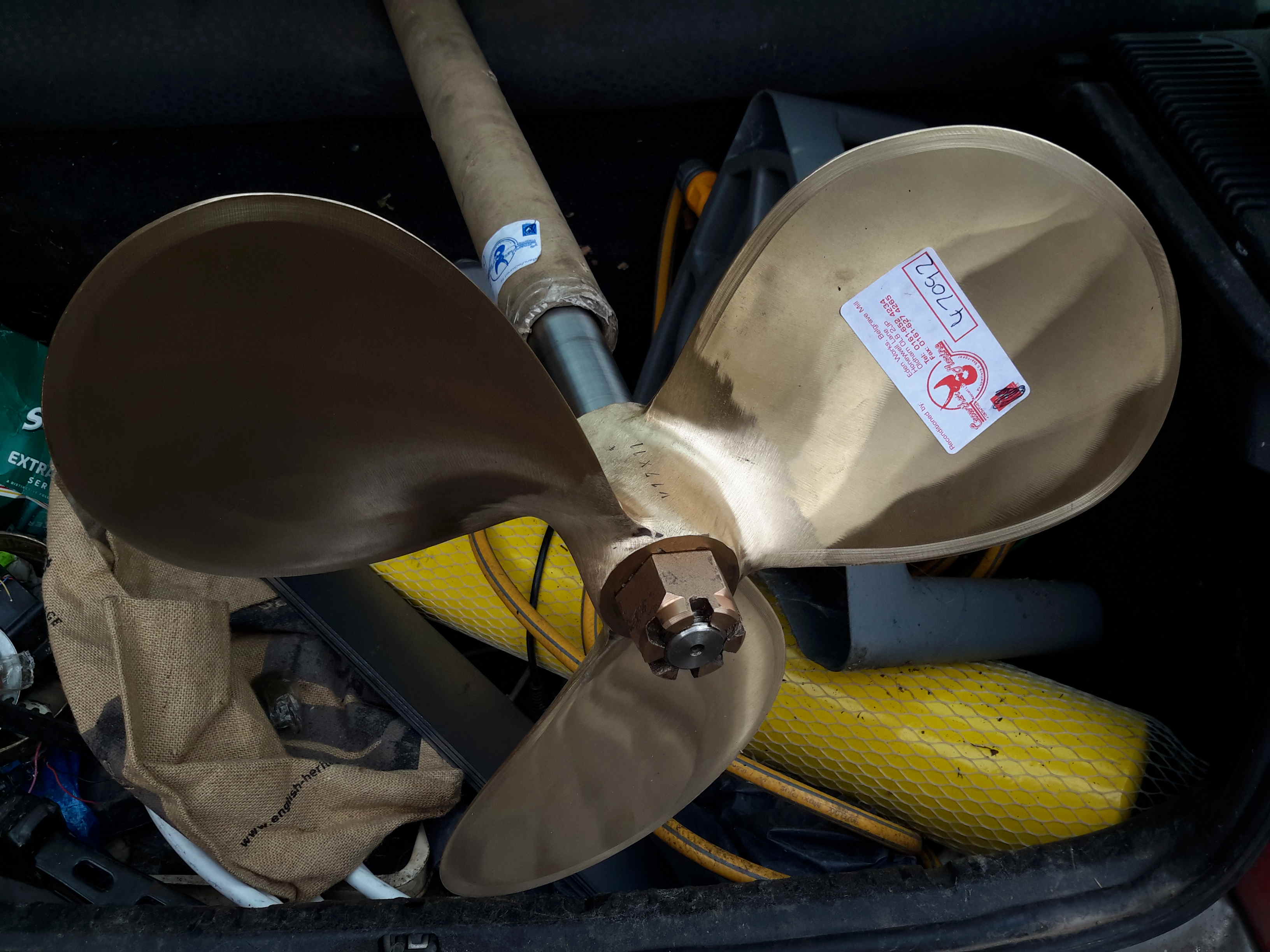
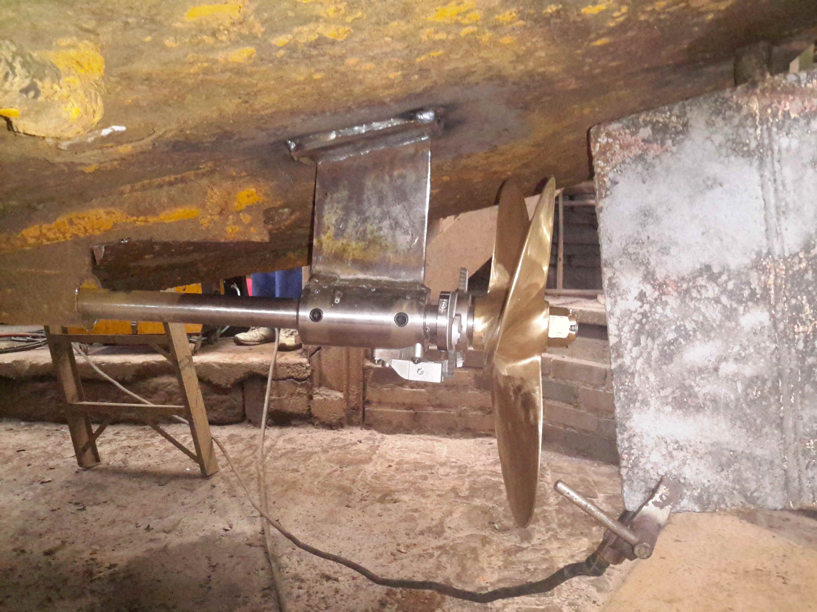
We’re now on the final leg of the jobs to be done on the boat! Above is the new prop & shaft, supplied to us by Crowther Marine over in Royton. To fit our current stern tube & gland, the shaft is the same diamter at 1-3/8″. Unfortunately no 4-blade props were available, so I had to go for a 17×11 left-hand, but with a much larger blade area than the old one.
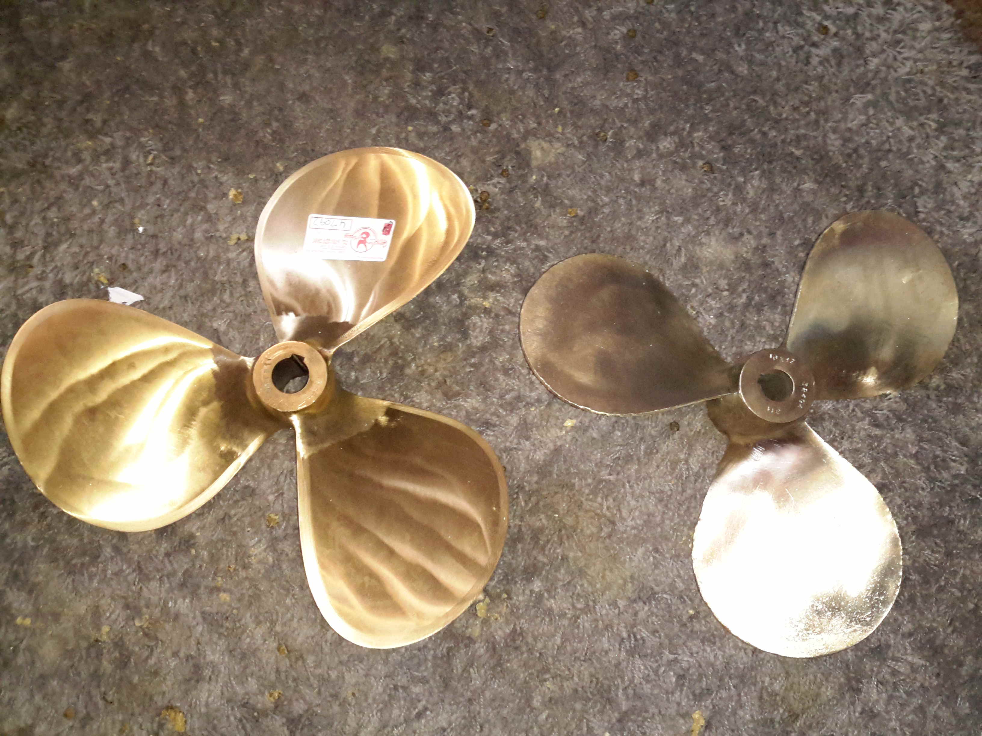
Propellers
Here’s the old prop on the right, with the new one on the left, amazing how different 1 inch of diameter actually looks. The opposite hand of the new prop makes no difference in our case, as I can simply switch the hoses to the hydraulic motor on the shaft to make everything reverse direction.
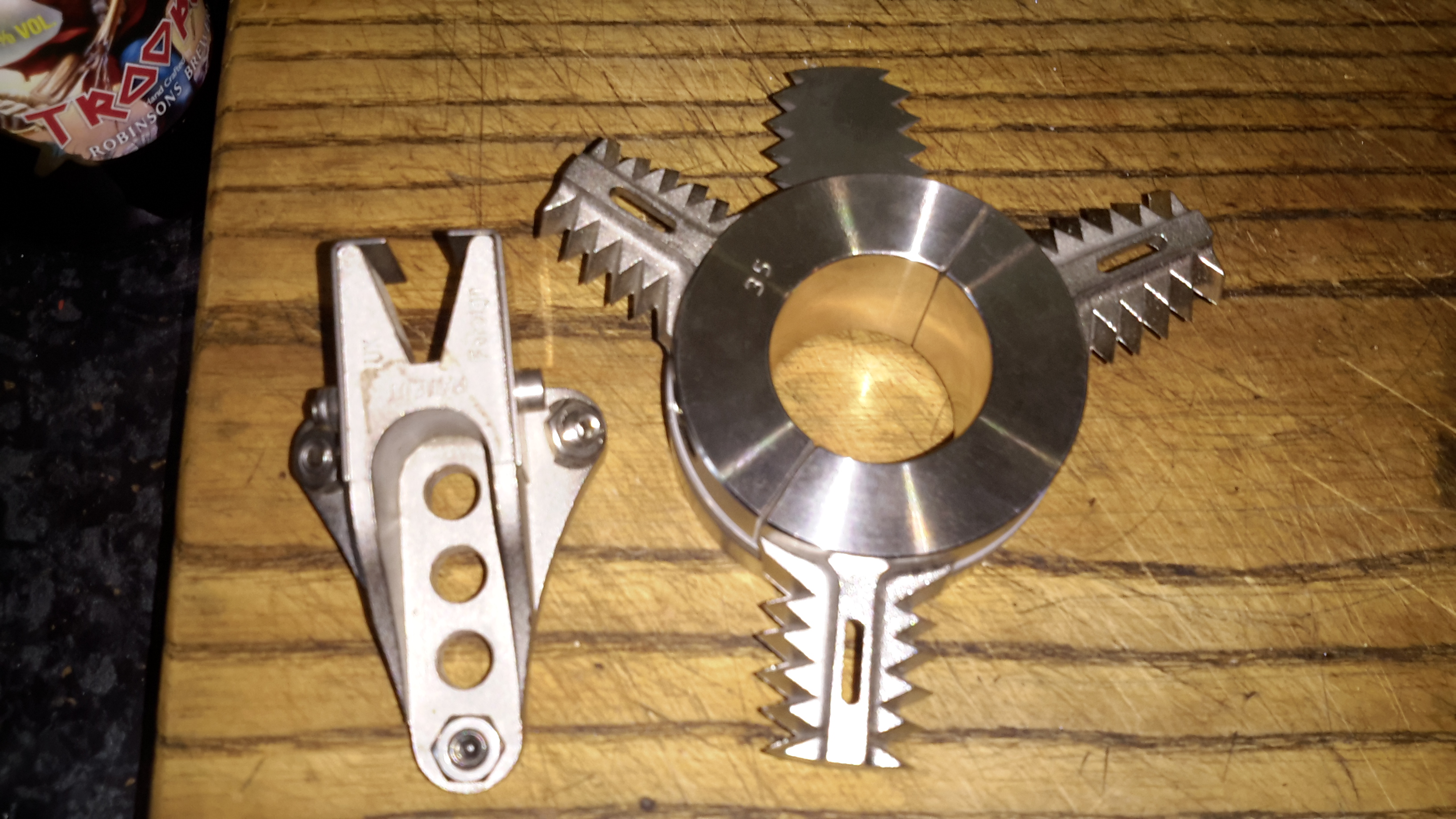
Stripper
Above is the solution to my problem of no weed hatch – a Stripper Rope Cutter from Ambassador Marine. This device has some seriously viciously sharp cutting teeth to help clear any fouling from the prop in operation. Only time will tell if it’s effective at allowing me to stay out of the canal manually removing the crap!
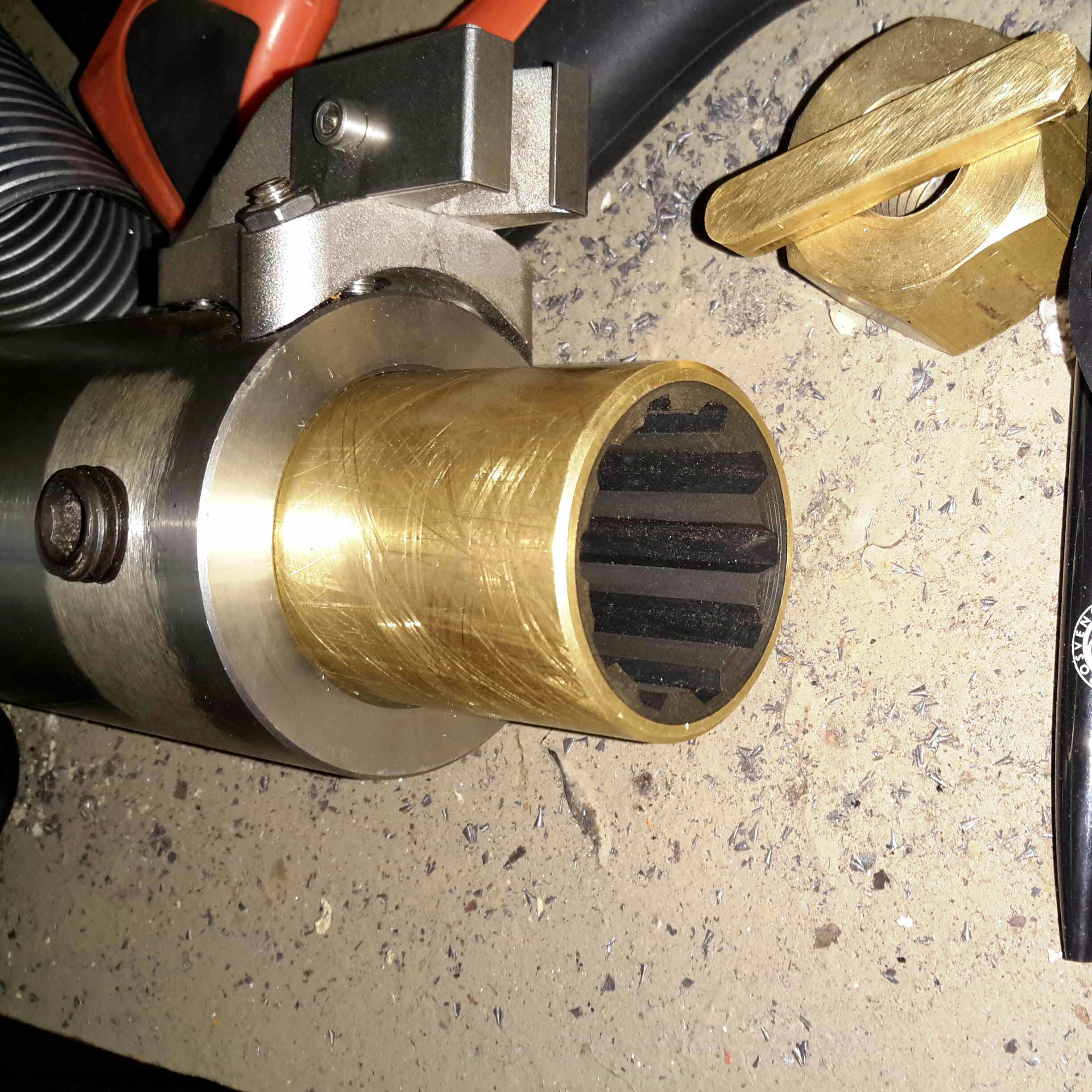
Cutless Bearing
We finally got the bearing mount finished, by S Brown Engineering in Stockport. This is made from Stainless steel to stop the bearing corroding in place & becoming a real arse to replace. Set screws are fitted to make sure the bearing doesn’t move in service.
Attached to the side of the bearing housing is the fixed blade mounting for the Stripper Rope Cutter.
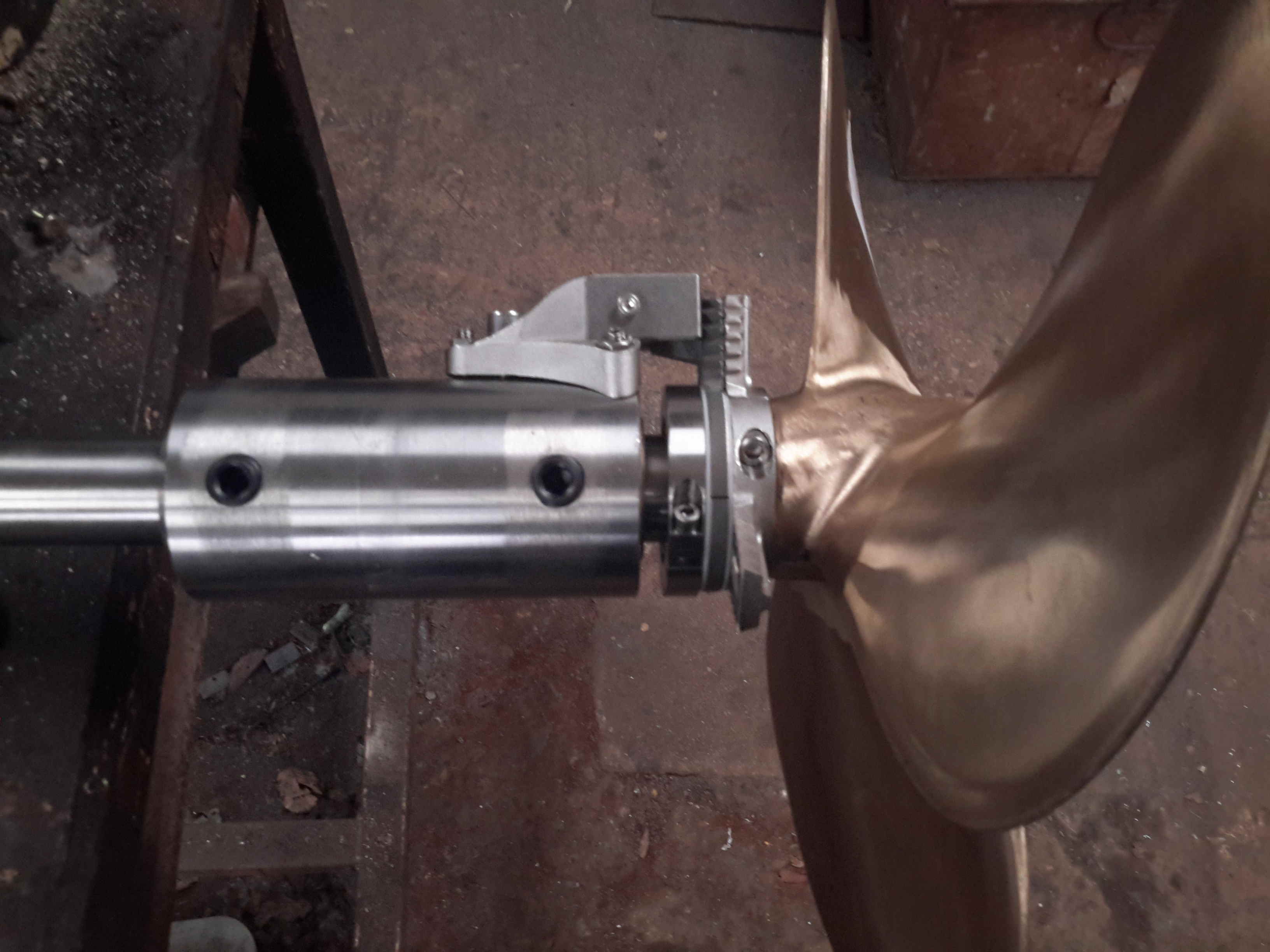
Bearing Test Fit
Above is everything fitted to the shaft for a test before the gear went into it’s home in the stern tube. The Stripper mounts behind the prop, clamped to the shaft. The 3 moving blades move against the fixed blade like a mechanised pair of scissors.
Bearing Strut Welding
10mm steel plate has been used to make the strut for the bearing tube, welded together. In the case of the joint between the stainless tube & the carbon steel strut, special welding rods were needed, at the price of £2 a rod! Using mild steel rods to weld stainless could result in cracking of the welds. Not a good thing on a prop shaft support bearing.
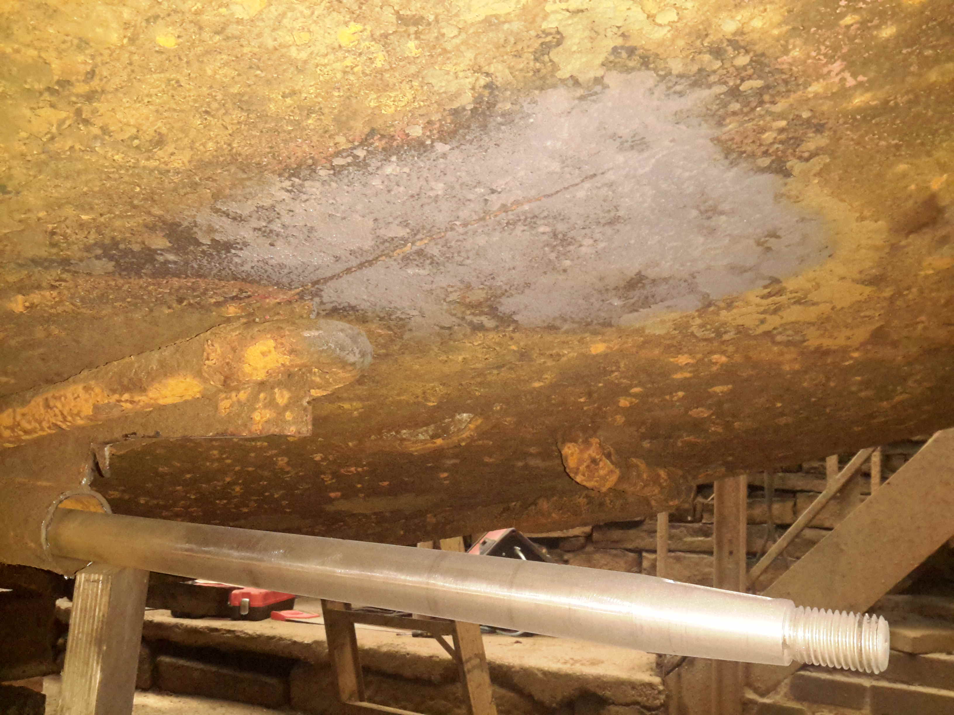
Sand Blasted Hull
Most of the old tube has been cut away to make room for the new bearings, and the bottom of the hull has been sand-blasted ready for welding.
Running Gear Mounted
The bearing mount is welded to the hull, the Stripper & the prop are fitted to the end of the shaft. There’s 1.5″ of clearance from the blade tips to the hull plating. The rudder has about an inch of clearance to the end of the shaft.
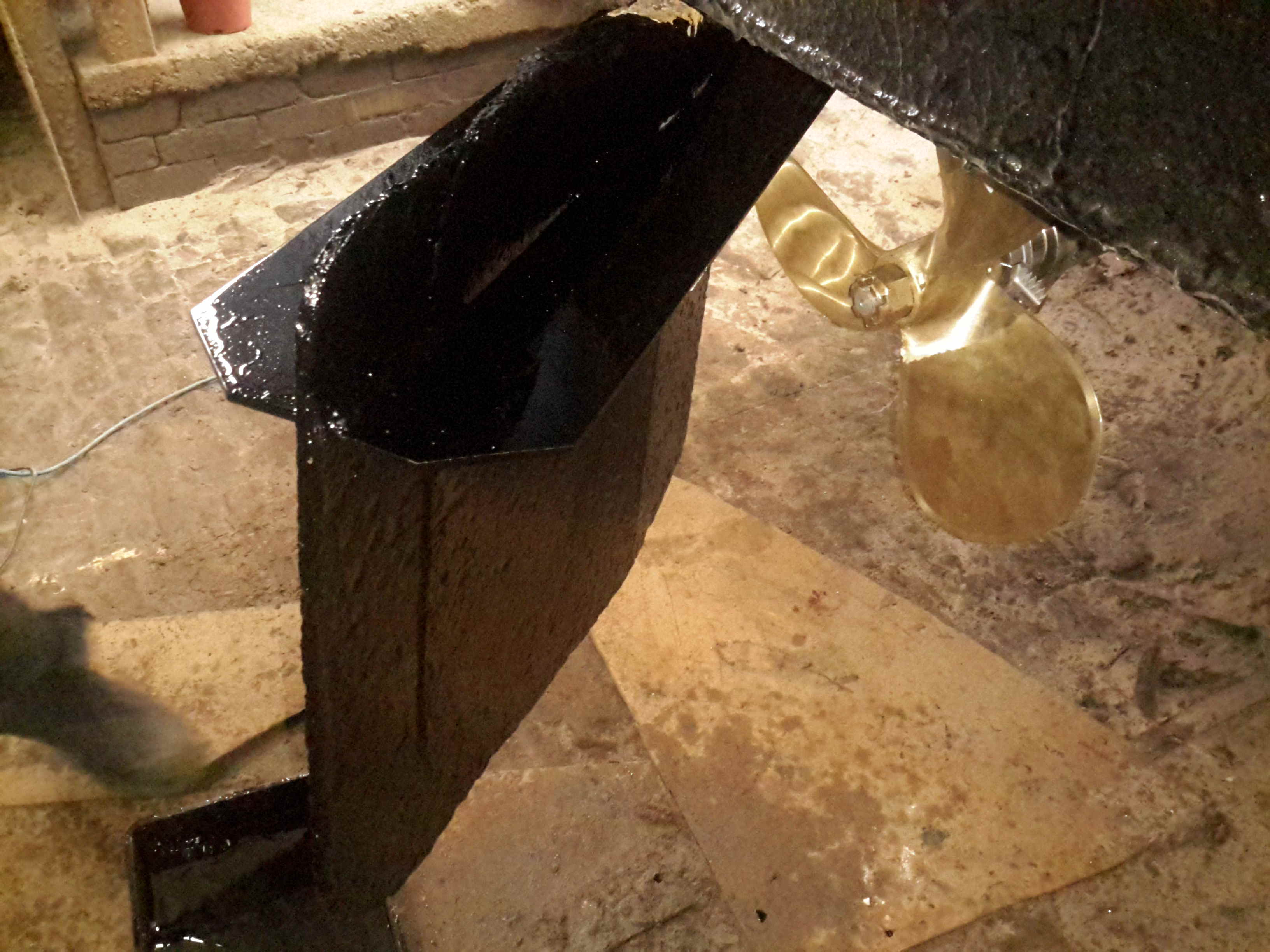
Rudder Fence
To help keep the prop wash down, directing more of the force into moving the vessel rather than creating a nice rooster tail, a pair of plates has been welded onto the rudder. These also provide a handy step should someone fall in ;).
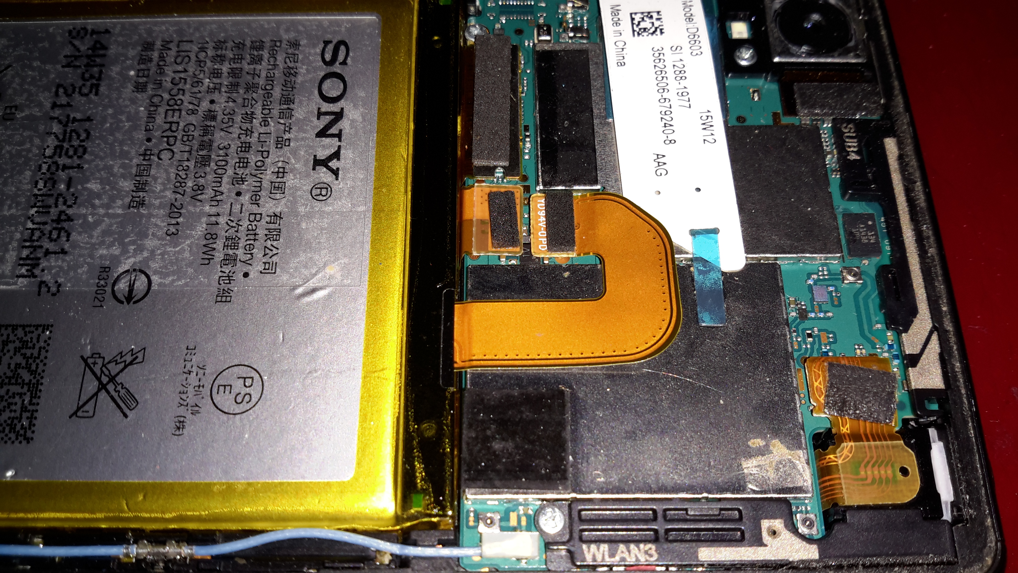
Recently my phone decided it was going to die a battery-related death, and having not found much useful information on the Great Google, (all the information I could find, was hinting at many issues from firmware to a faulty motherboard, nobody seems to have actually done any investigation into similar issues), I decided to dig into the phone to try & repair the problem.
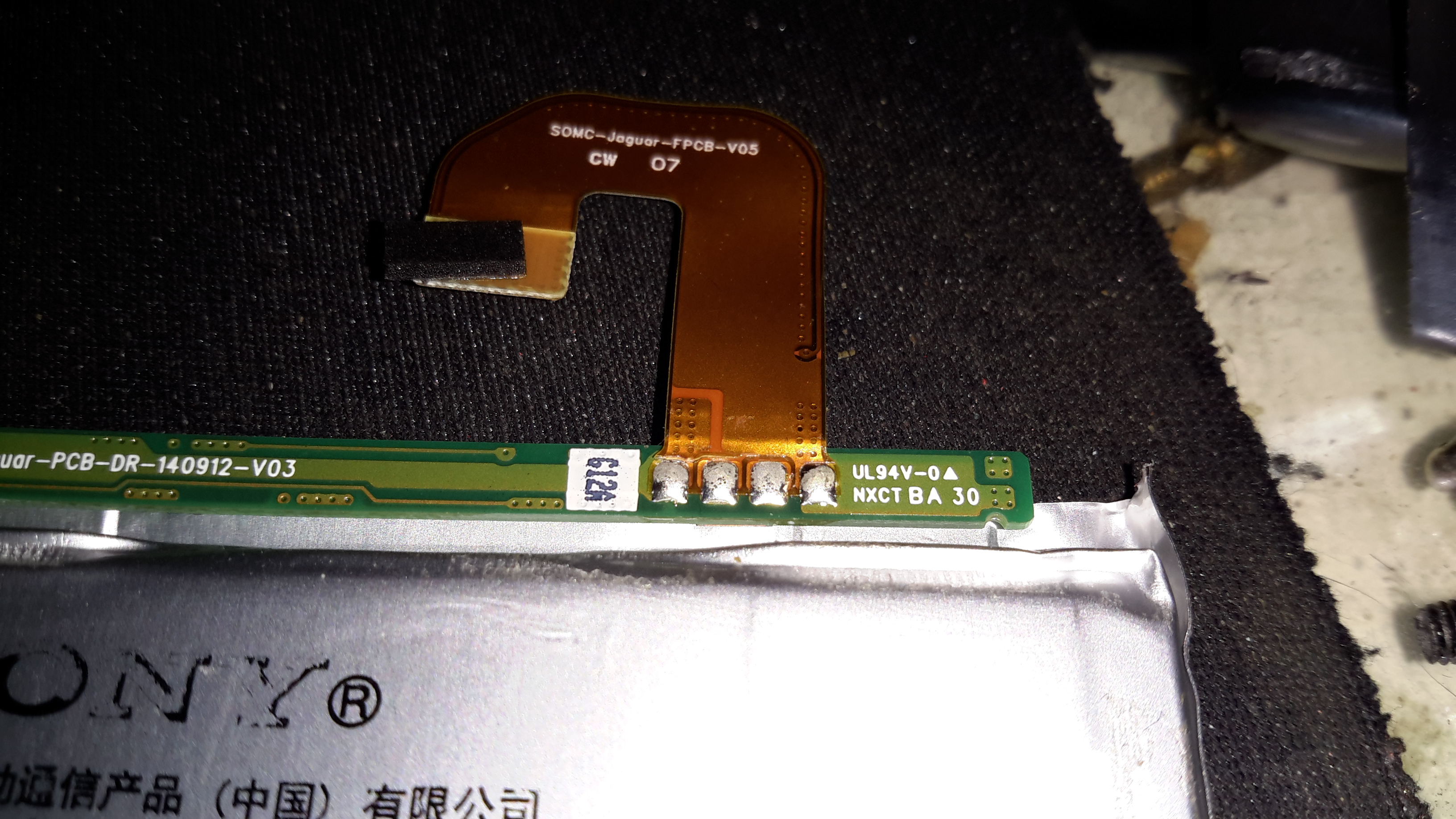
Broken Flex
The phone would work correctly for a while, then with the slightest movement or knock, would spontaneously switch off, and not turn back on without being whacked on a hard surface.
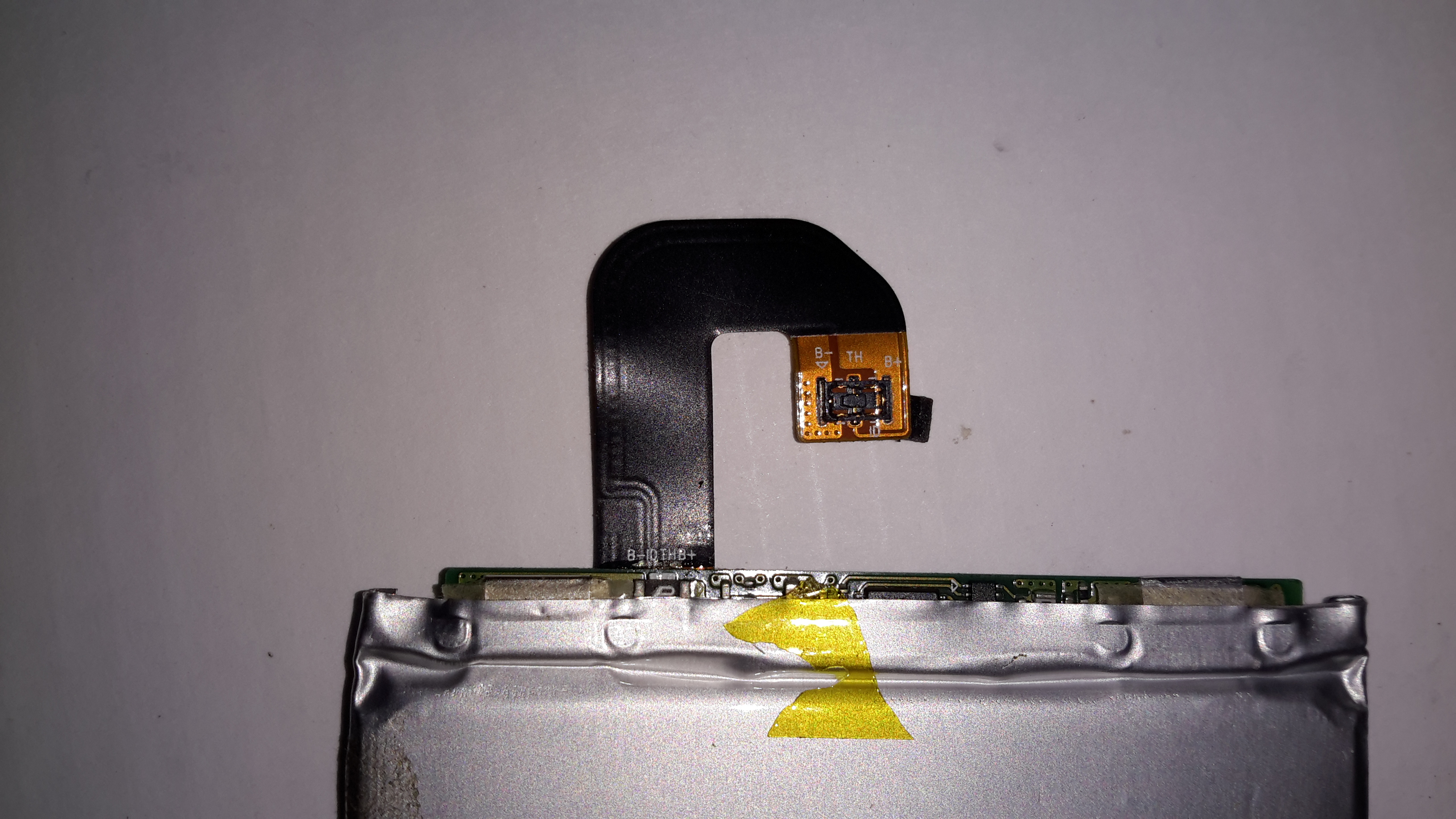
This symptom pointed me at a power connection problem. After removing the back of the phone (glass & heavily glued in place, so an awkward process), This was what I was presented with on the cell flex PCB.
In the above photo, the positive connection to the flex is fractured just after the solder joint with the BMS board.
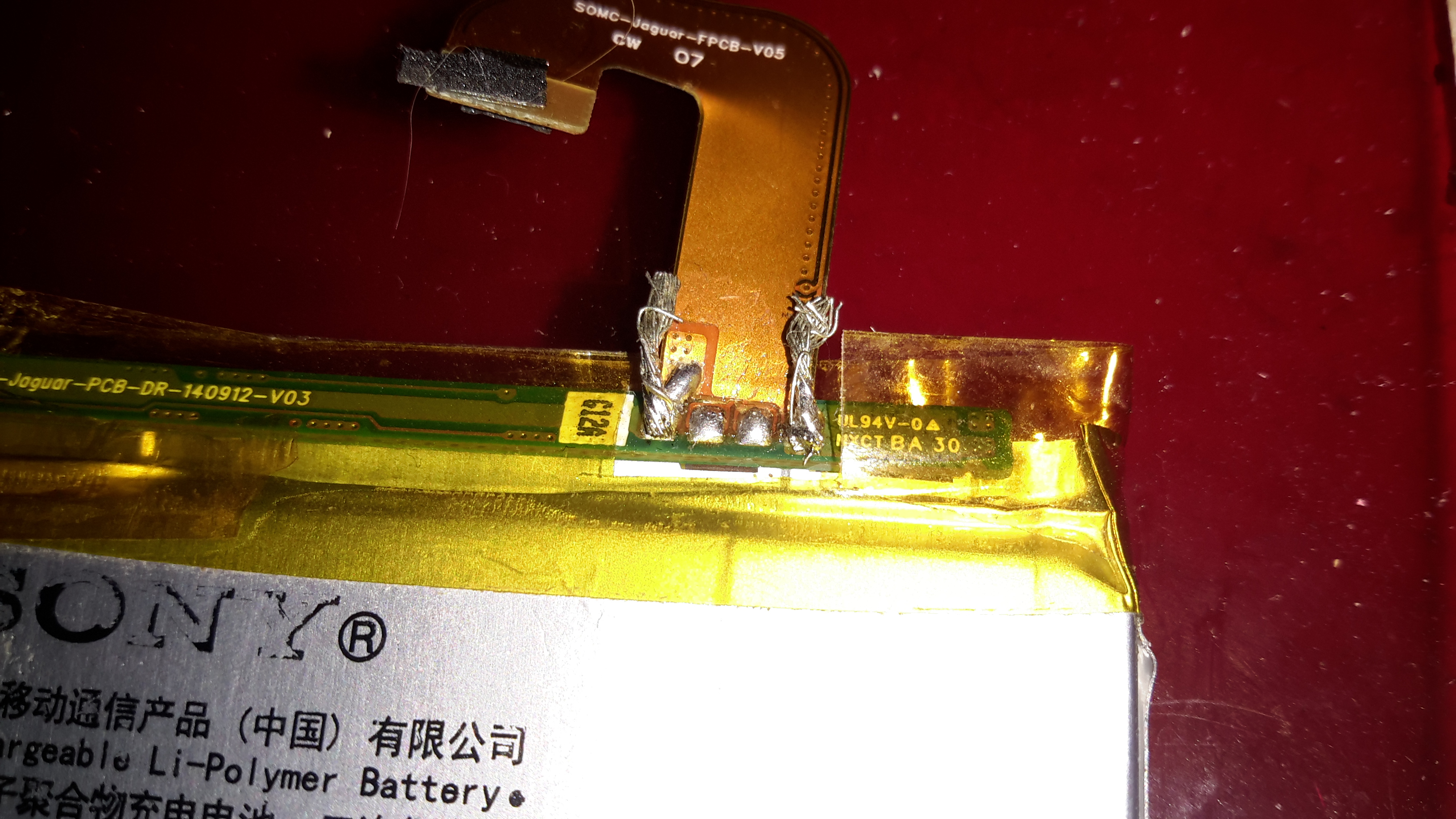
Flex Repair
I managed to scrape some of the insulation off the flex PCB & solder a jumper on to restore power. Unfortunately, this repair generated another fault, where the battery level was always shown at 50%, and plugging into a USB supply wouldn’t charge the phone. The other two pins on the cell are for communication & temperature sensing, clearly one of these traces was also broken in the flex.
The above photo has a pair of very small wire tails as well, for connecting an external charger.
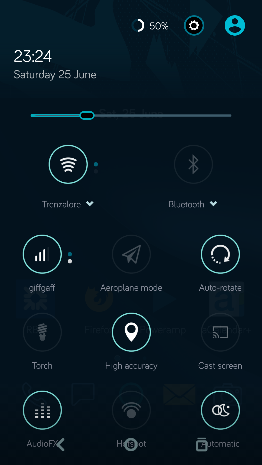
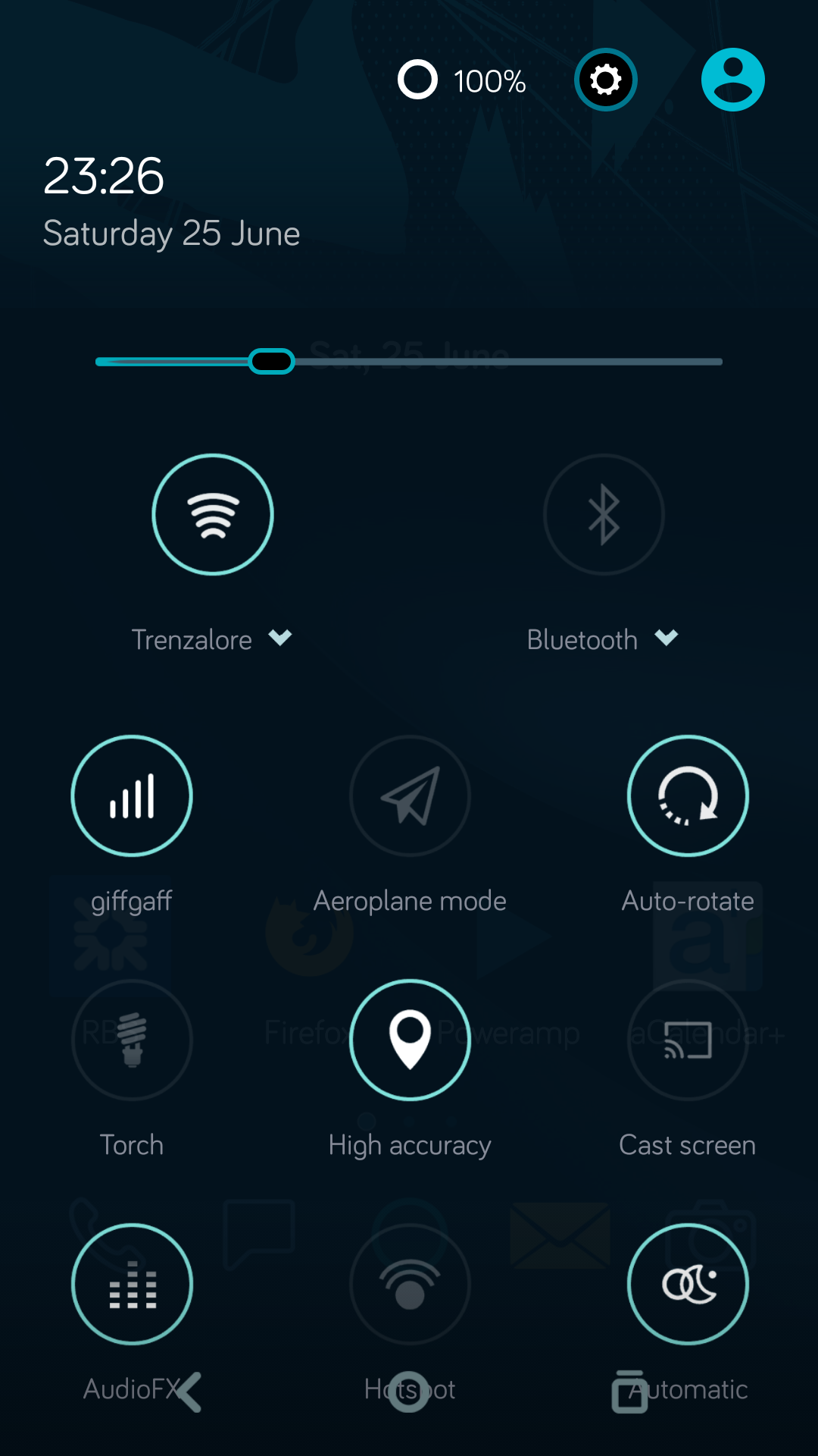
50% Battery
Here’s a screenshot of the phone with the original cell, even though it’s at about 4.15v (virtually fully charged). The battery management is having trouble talking to the phone, so for safety reasons, the charging logic refuses point-blank to charge the thing up.
Flex Cable
The connector on the cell & phone motherboard is absolutely tiny, so I didn’t fancy attempting to solder on any bridge wires to try & bypass the broken flex.
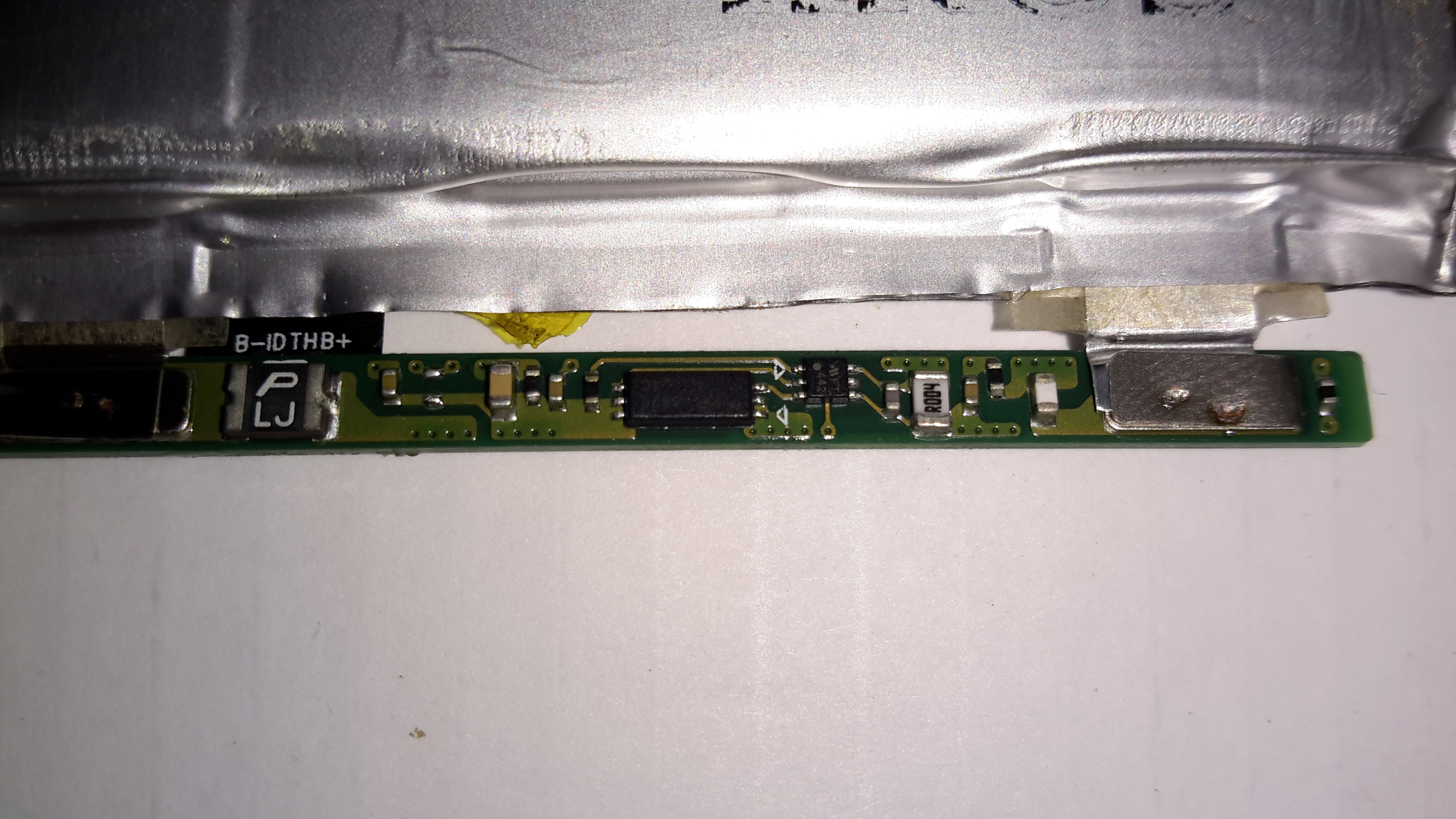
Battery BMS
The cell BMS has some intelligence on board, besides the usual over-current, over-charge & under-charge protection. The very small IC on the right has a Microchip logo, and the marking FT442, but I was unable to dig up any datasheets. The current sense resistor is directly connected to this IC, along with the main power FET to the left.
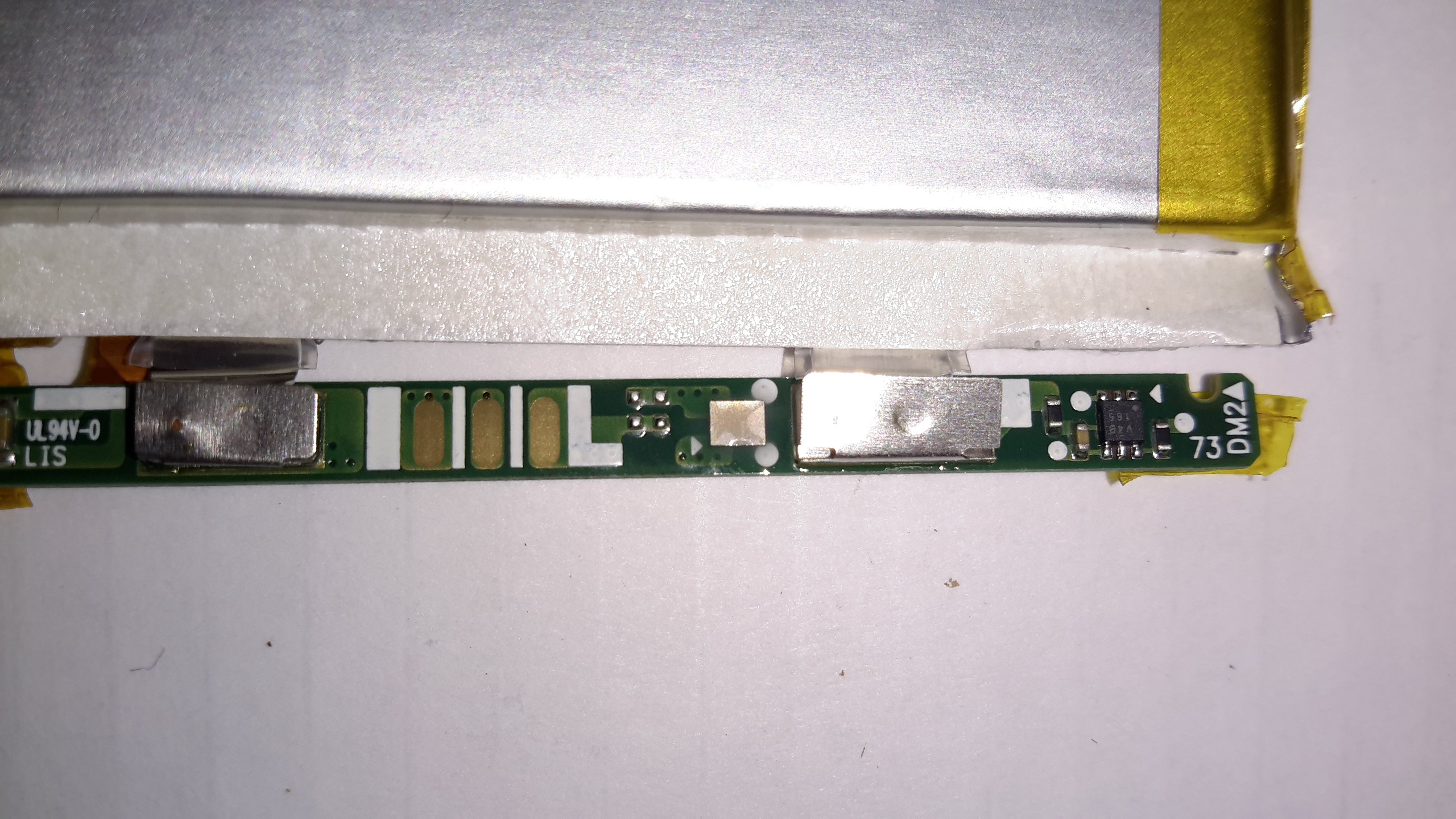
BMS Reverse
On the other side of the BMS board is another IC, again unidentifiable, and what looks like a bare-die, or CSP IC.
At this stage I figured the only way forward was to buy a new battery, eBay turned one up for less than £5. Above is the new battery fitted to the phone, datestamped 2014, so definitely old stock.
100% Battery
Booting the phone with the new battery quickly lets me know the fix worked, with a 100% reading & the ability to again charge properly!
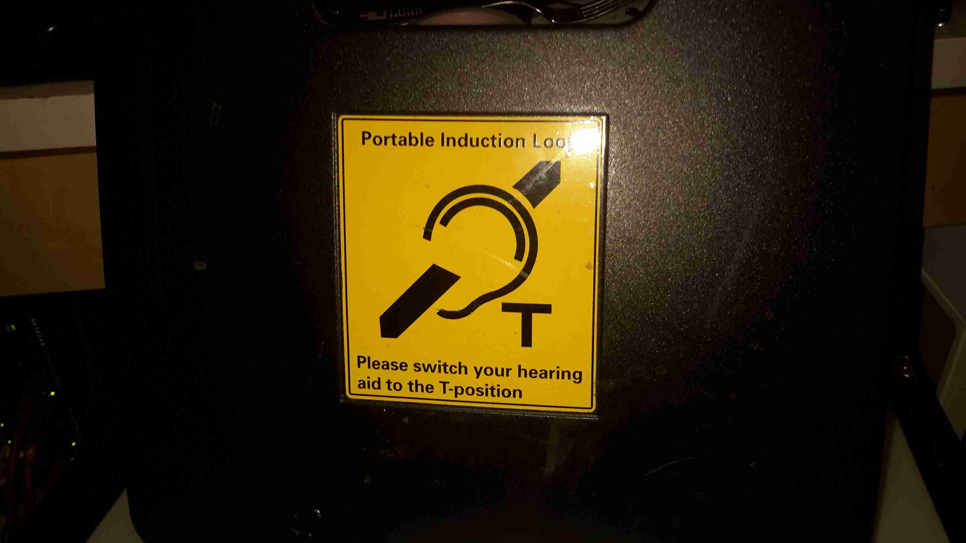
These units are used to broadcast local audio, such as from a public address system or local microphone. They accomplish this by producing a modulated magnetic field that a hearing aid is capable of picking up.
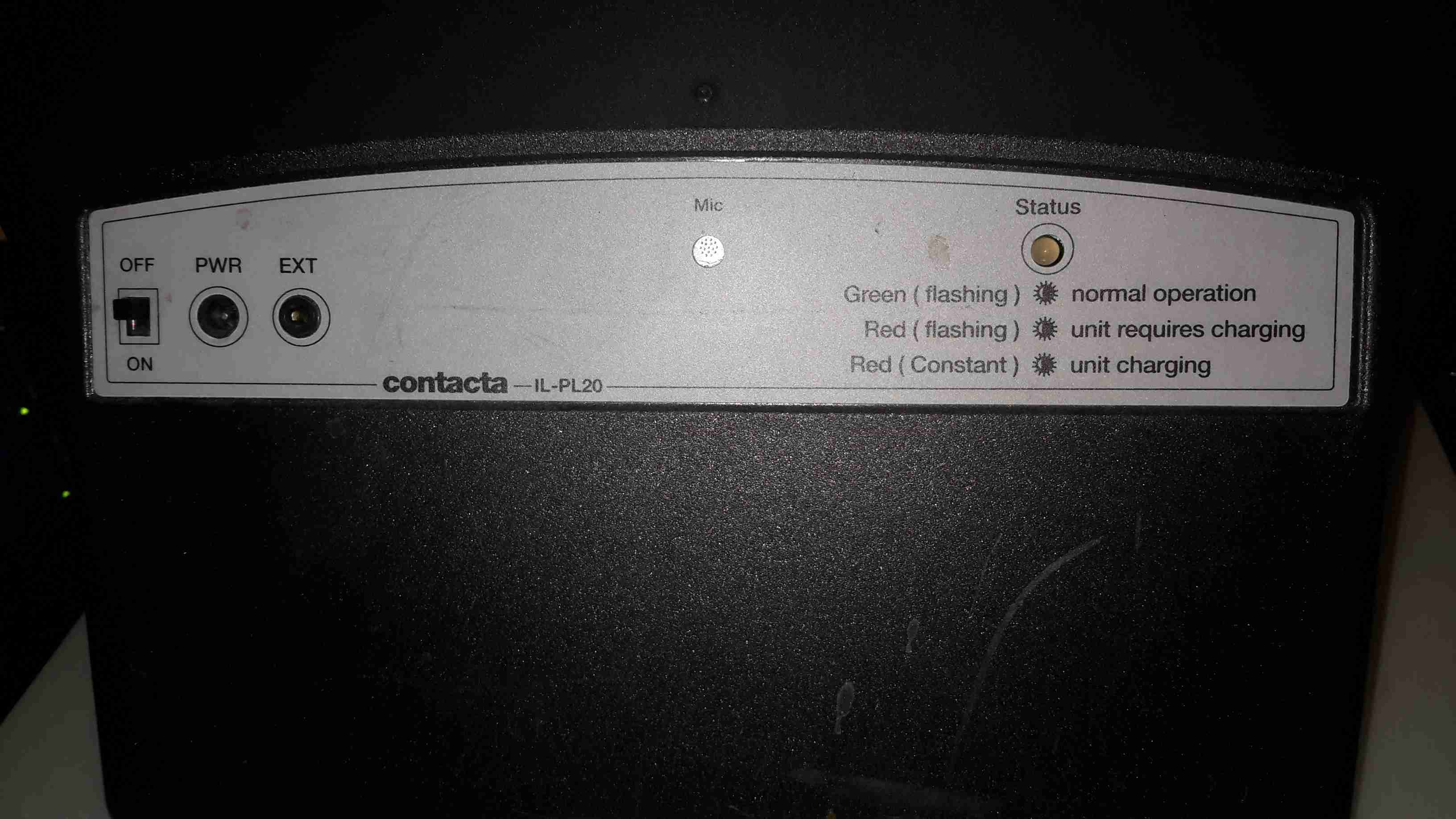
Back Panel
Not many controls on this bit of equipment. A bi-colour LED for status indications, a microphone, external audio input, charging input & a power switch.
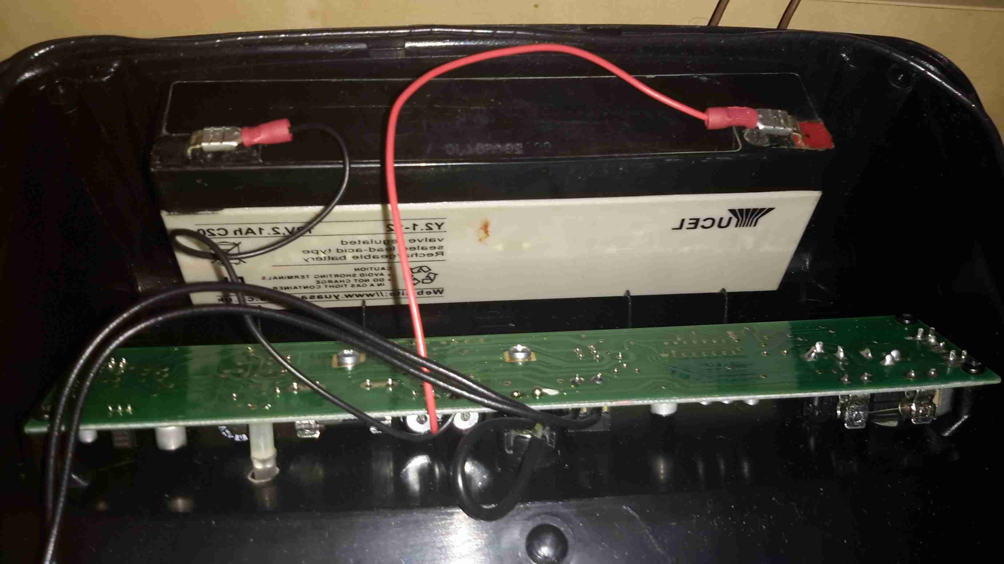
Internals
Popping the cover off reveals a small lead-acid battery, 2.1Ah at 12v. This is used when the loop is unplugged.
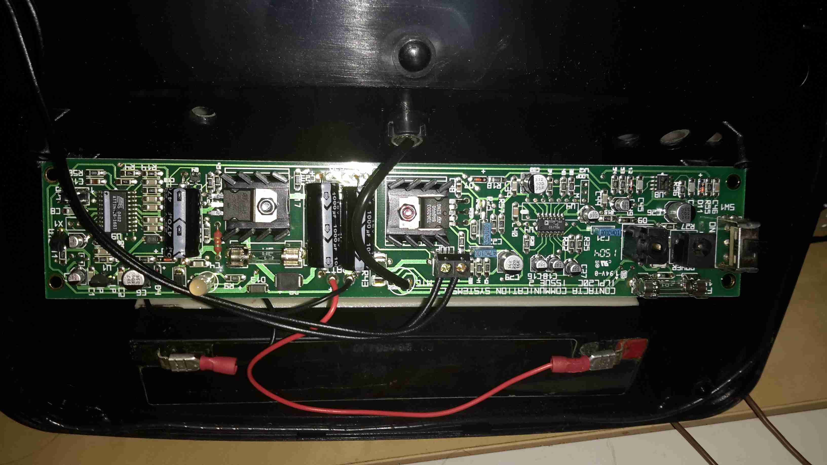
Main PCB
Here’s the main PCB, which takes care of the audio & battery charging. The inductive loop itself is just visible as the tape-covered wire bundle around the edge of the casing.
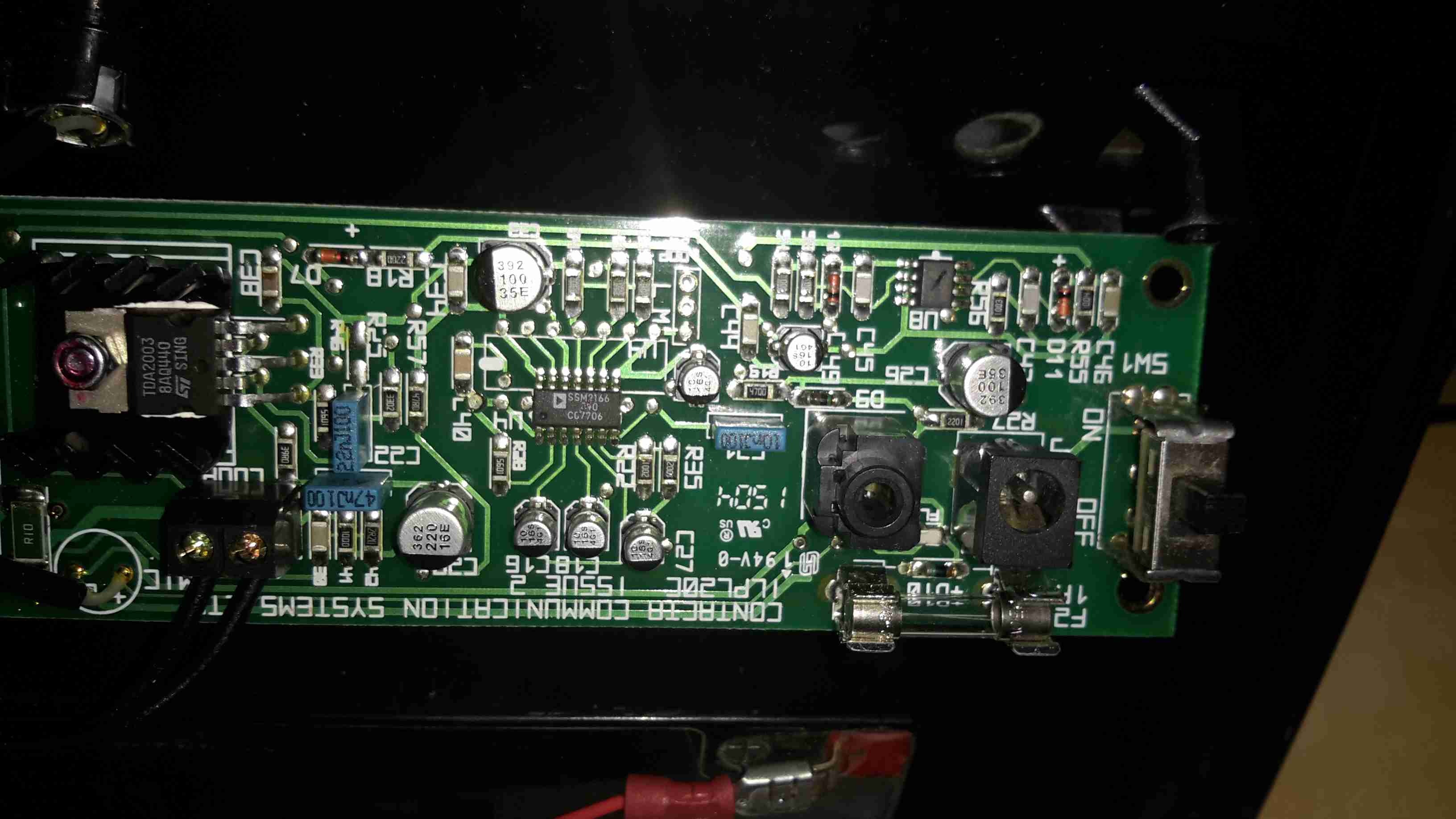
Audio & Power Input
Here’s the input section of the main PCB. The microphone input is handled by a SSM2166 front-end preamplifier from Analog Devices.
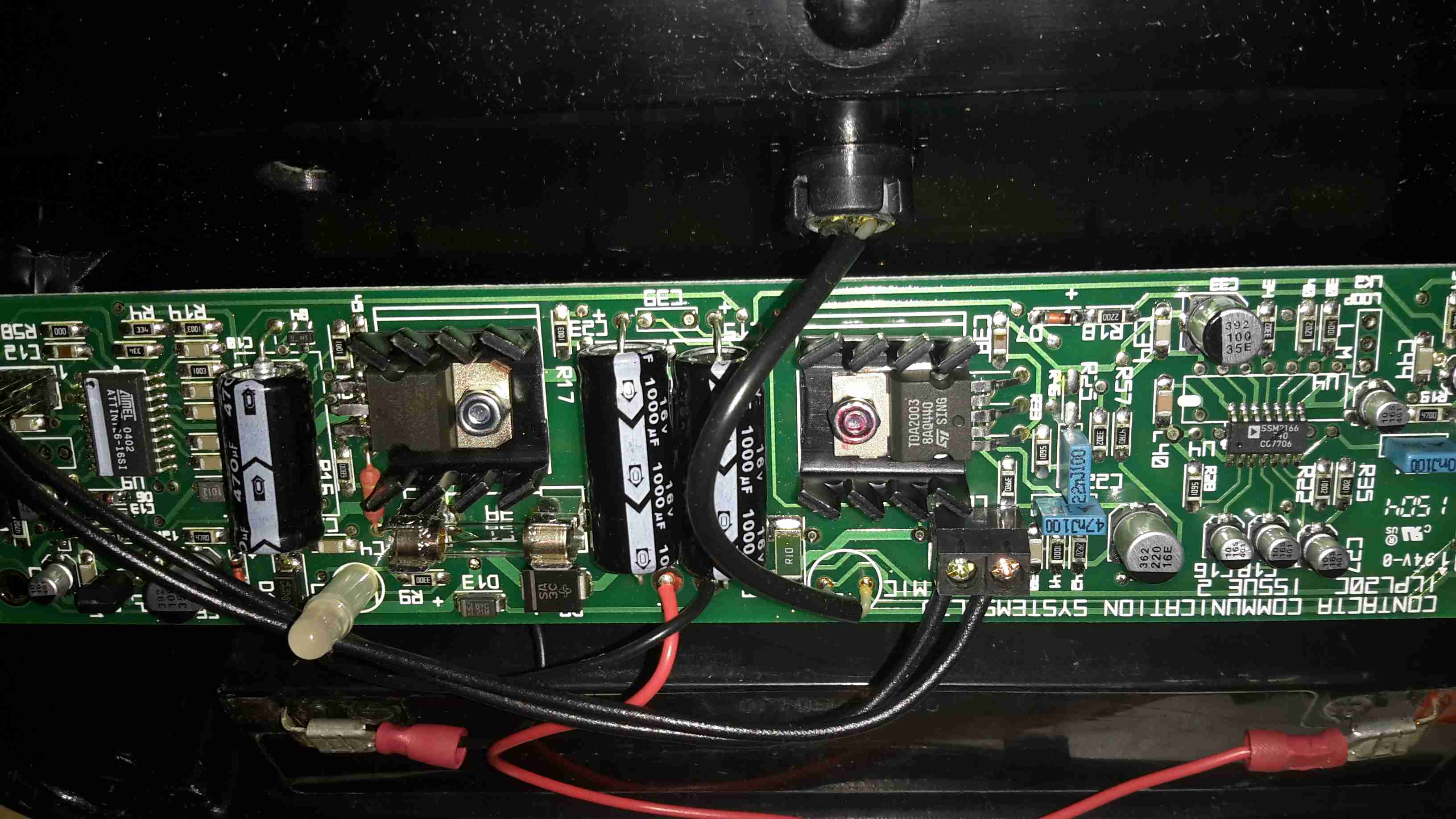
Power Amplifier
This audio is then fed into a TDA2003 10W Mono Power Amplifier IC, which directly drives the induction coil as if it were a speaker. Any suitable receiving coil & amplifier can then receive the signal & change it back into audio.
It’s well known that there are two versions of the 701 type controller available for Eberspacher heaters, the version with the blue logo is the official un-restricted model, while the version with the white logo is a version built for BT that restricts the heater to 1 hour runtime & has no diagnostics built in.
As these devices are microcontroller driven, I assumed that the hardware would be the same, only the code running in the micro being the bit that Eberspacher changed. This option would certainly have been the lowest cost.
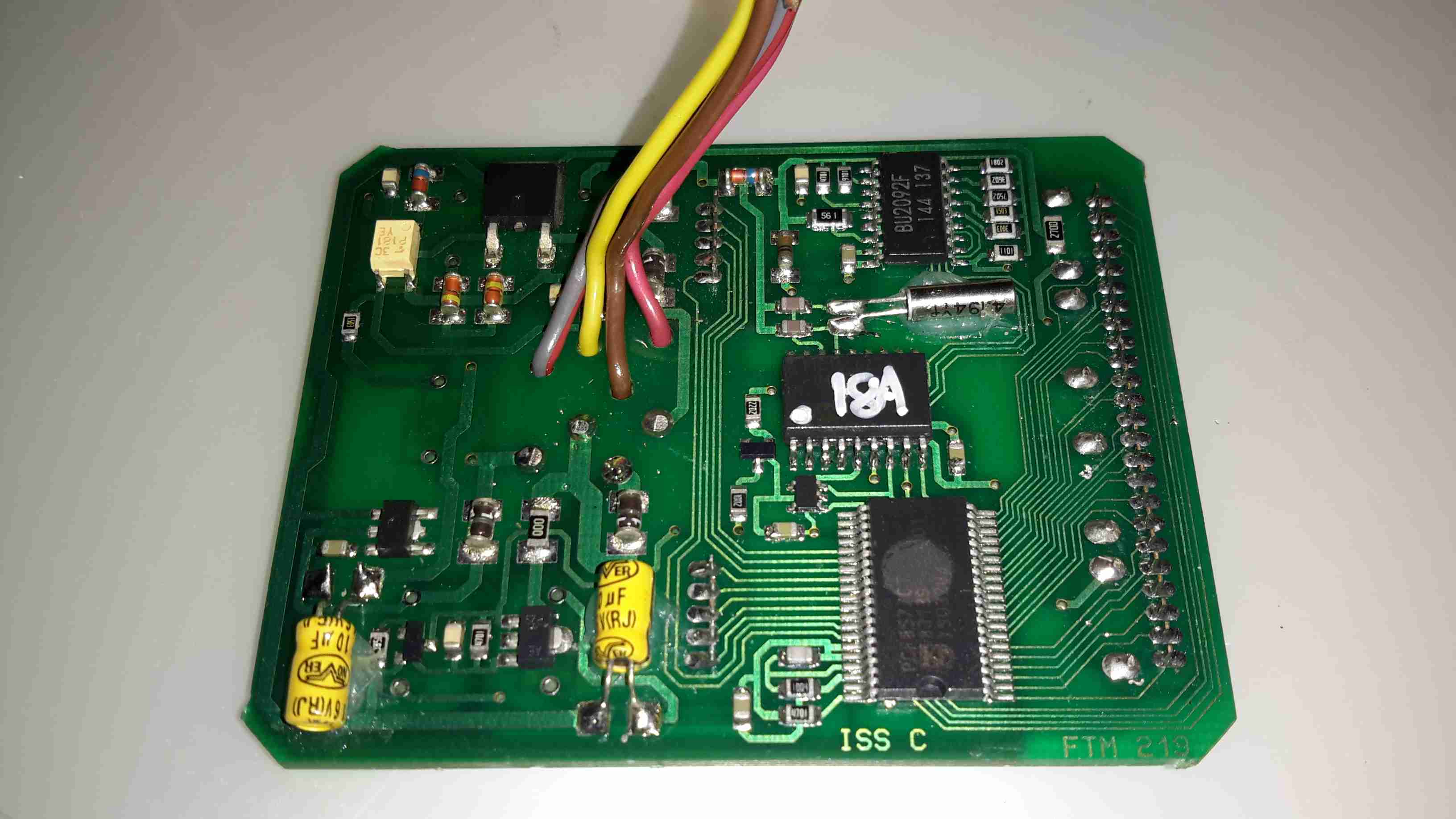
Controller PCB Rear
Here’s the PCB removed from the plastic housing. There are definitely some differences that I can tell. As the un-restricted version has an extra wire for the diagnostic serial interface, and this board has no unpopulated parts, the PCB is definitely a different version.
In the centre is a Microchip PIC16C622 microcontroller, the OTP version in this case for cost reductions. (I may try reading the binary from this chip in the future, chances are it’s code protected though).
Below the micro is an NXP PCF8577C 32-segment LCD controller, this has an I²C interface to the PIC.
The temperature control function on these heaters is done via applying a resistance to one of the control lines, between 1750Ω-2180Ω, ±80Ω. (Very odd values these, not to mention no standard components can create this range easily, bloody engineers >_<). This is accomplished in hardware with a BU2092F I²C shift register from Rohm, which is connected to a bank of resistors. The microcontroller will switch combinations of these into the circuit to get the range of resistances required.
The rest of the circuit is local power regulation & filtering.
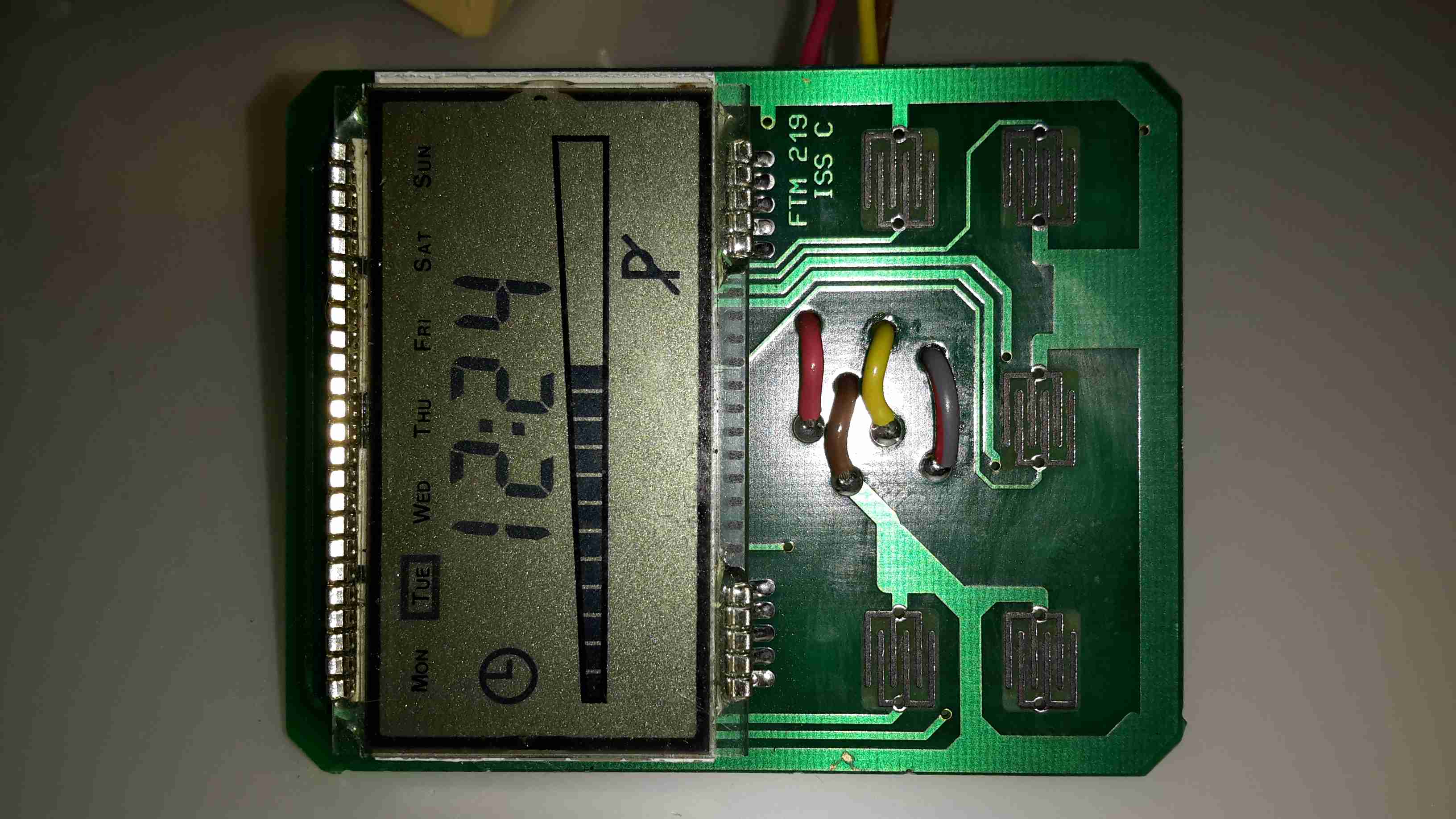
Controller PCB Front
There’s not much on the other side of the PCB, just the LCD itself & the contacts for the buttons.
Compressed air is a rather useful power source, especially when all maintenance is done by the on board crew instead of by boatyards.
Screwfix had a good deal on a 50L 3.5CFM air compressor, to save space this has been permanently mounted in a free space & air will be piped to where it is needed from a central point.
Because of the total height of the machine, the compressor itself has been unbolted from the tank, a copper line connecting the two back together at a larger distance.
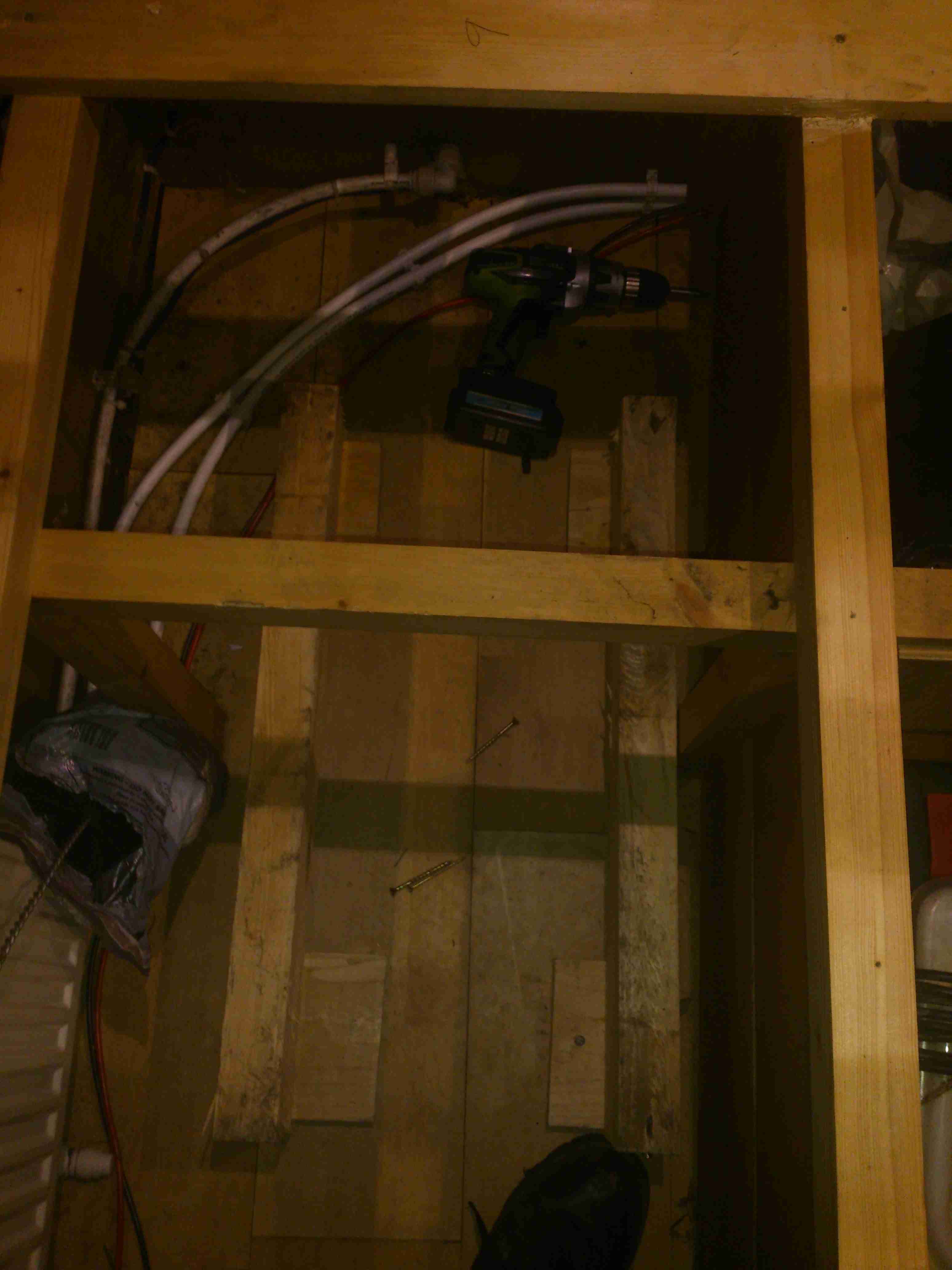
Bearers
In one of the very few free spaces available, under a bunk. A pair of timbers has been screwed to the floor to support the tank.
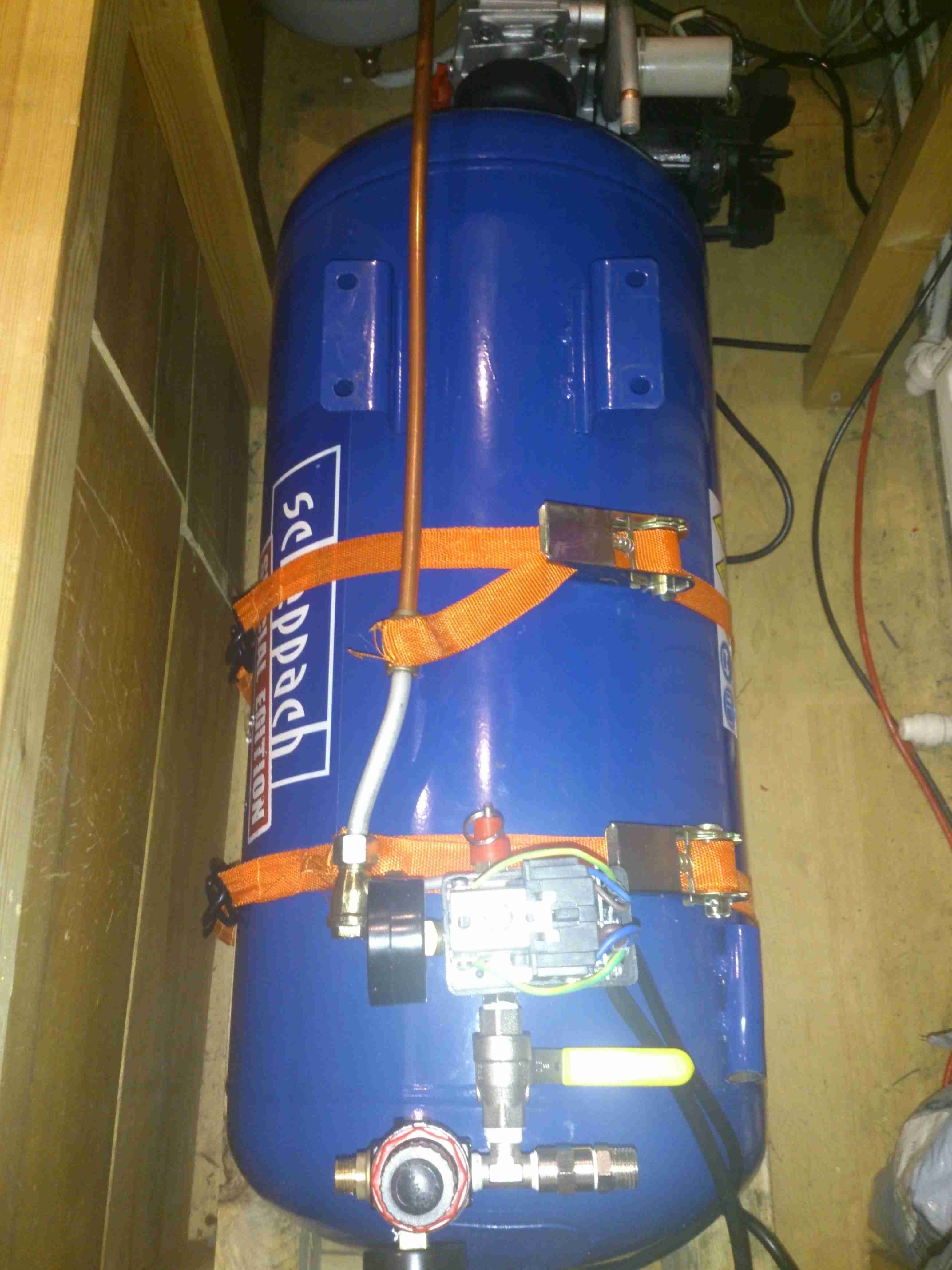
Tank Installed
The tank is strapped to the wooden supports with a pair of ratchet straps, the compressor itself can be seen just behind the tank. The copper line on the top of the tank is going back to be connected to the compressor outlet.
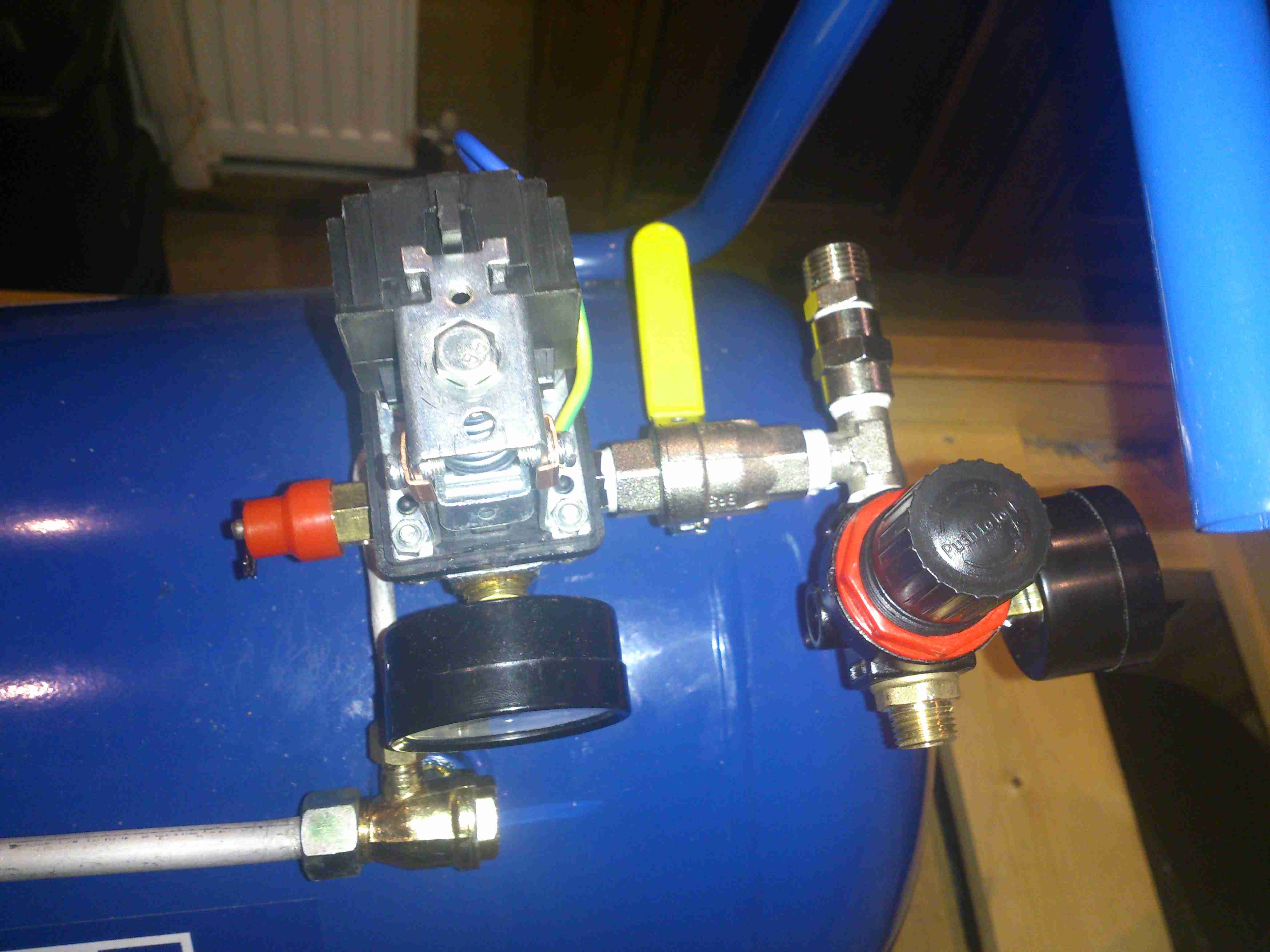
Air Fittings
Compressor control remains on top of the tank, the pressure switch & relief valve centre. After an isolation valve, the feed splits, the regulator installed will be feeding the air horn with 20PSI, replacing the existing automotive-style 12v air pump. The currently open fitting will be routed to a quick connect on the bulkhead. This will be accessible from the front deck, an air hose can be fitted to get a supply anywhere on board.
More to come when the rest of the system gets installed!
It’s been a while since I’ve done a proper radio based post, so it’s a bit of a shame that I have to start off with a rant, but it’s required in this case.
One of the local 70cm repeaters, GB3WP seems to have many problems. The largest one seems to be G6YRK, the repeater keeper.
I had heard rumours of the repeater suddenly going off air getting switched off when either an M3/M6 or 2E0/2E1 was using it. At the time I thought no fellow ham could be quite that petty.
What callsign I or anybody else has should not make a shred of difference whether we should be allowed on the air or not. I personally keep my operating standards as high as possible, way above and beyond what Ofcom stipulates in the licence terms, as it’s part of making the hobby enjoyable for everyone. Seems that not everyone feels the same (in my experience, the older generation of hams, some of whom believe that the tests these days are far too easy, etc, etc).
Then I got proved wrong.
I was doing some handheld radio testing with M3HHY over at Distant Signal Radio on GB3WP, as at the time GB3MR was having some issues with the local pirate (see my previous posts for more info on that prat).
Within a couple of minutes of us establishing a QSO, the repeater suddenly stopped responding. After trying to get back in for a good 15 minutes, it came back on air again.
The instant we gave our callsigns, off it went, into the ether. No response.
This behaviour continued for nearly an hour, and after trying to contact YRK directly, we gave it up as a bad job, with quite a bit of pissed off added into the mix.
If I’d not heard stories of the repeater being turned off when the “wrong people” are using it, I might have put it down to dodgy repeater equipment, but even that didn’t make sense, as it had a definite pattern.
We both fired off an email to the Repeater Keeper, only to get no response from that either (surprise, surprise).
That was the last time I personally attempted to make use of GB3WP.
Until I was given an audio clip of G6YRK in action this evening.
Seems that not even M0 calls are immune from being wiped off the air by GB3WP. Chris, M0OGG, has apparently also had this issue with the repeater. Lucky for him, he had the opportunity to speak to the keeper directly about what went on.
Here’s the audio, I’ll pick each part out & go into a few opinions/observations below.
So, Chris (M0OGG) has asked a simple question, and been met with hostility. Dick Move Number 1.
YRK is clearly reluctant to go into “detail” on the air. Probably because he’s talking complete shite. Only when Lewis (M3HHY) joins in with a slightly more defensive tone does Steve (G6YRK) actually say what Chris has been “reported” for.
After all that it seems that an accusation of keying over other repeater users is the bullshit line of the day. (For the record, I know Chris, he’s not the type of person to key over another radio user, that behaviour in of itself is idiotic).
Apparently he has witnesses to this action, and he’s insisting that others were also involved. Not to mention the fact that RDF has been done on (I’m assuming) all of these “offenders”. G6YRK must have quite the army of hams with lots of spare time.
I’m not sure who the other station is, as he doesn’t give a callsign.
As Lewis jumps in & comments, the Repeater Keeper should be saying something to users he suspects of this kind of thing, in my opinion.
The real reason, of course, that he keeps turning the repeater off when others are using it is that he’s a passive-aggressive vindictive moron.
Surprise, surprise, he can’t remember the “exact date”, (because it never actually happened), it’s just “the other day, somebody did it”. Yeah, great evidence there Steve, because apparently the only person around at the time was Chris. How can he know this? When a repeater has a coverage area as wide as GB3WP, this guy is claiming that he knows that only a single person is listening? No, I think it’s bullshit too.
GB3WP Coverage Map
For reference, here’s the coverage map of the repeater. Steve G6YRK must be bloody psychic to make such a comment.
He then mentions a “friend” of Chris, but again refuses to give any names. Again I’m calling bullshit.
Swifty following this he goes into full kick-my-toys-out-of-the-pram mode because he’s been openly challenged.
While he’s correct in his statement that he can do as he pleases with the repeater, it’s not very good form to just switch the thing off when licenced users are having a perfectly valid QSO. If he doesn’t like people using the repeater, he should turn it off permanently & remove the listing from the repeater group.
After this, Steve makes the comment that he knows nothing of the repeater going off, as he’s been out all night. He mentions his Repeater Stasi again, and then makes a partial retraction of his previous statement, now that it “might” not have been Chris previously. Well Steve, we’re finally getting towards something that resembles truth. You’ve got absolutely no idea who is “keying people out”, if it’s even happening at all. So much for “having people all over the place” listening to where transmissions are coming from.
After Chris confronts him again, he returns to the fallback of that as the NoV holder it’s his prerogative to be able to switch the repeater off whenever he pleases.
When confronted with the fact that people pay into the repeater group to help keep them running, he claims that Chris’ signal is breaking up. My arse. Every other station on the repeater can hear him fine.
There’s probably more to add to this, so if I get any more relevant information from other sources I’ll add on to the saga.
Since the boat was still running it’s internal network on 10/100M speeds, an upgrade was decided on, the internal WiFi signal strength was also pretty poor further than a few feet from the NOC.
The new router is a Cisco/Linksys AC1750 model, with gigabit networking, and full 802.11ac 2.4/5GHz Wireless. This router also has a built in media server, print server, USB3 & USB2.
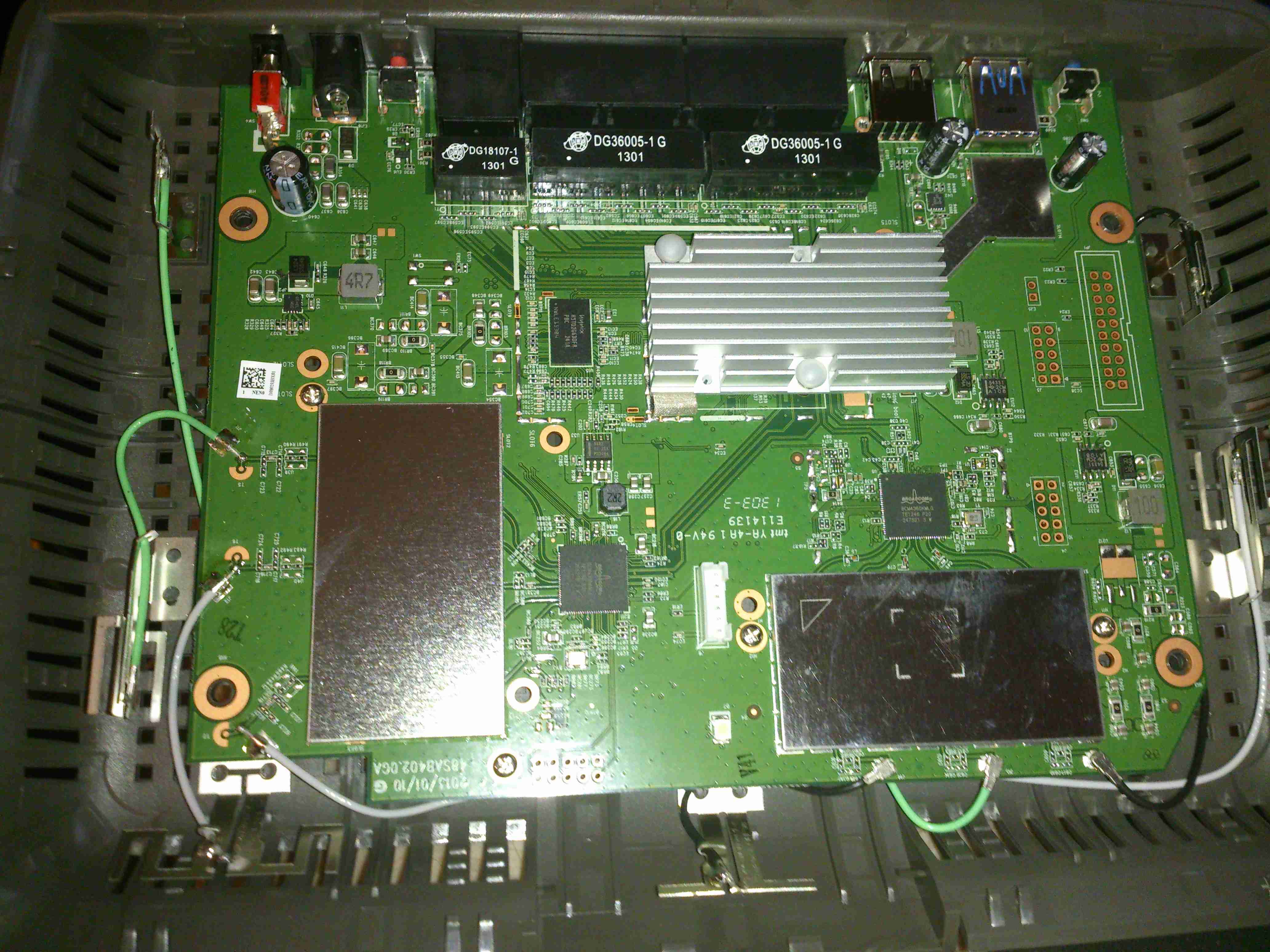
PCB Overview
Teardown time! Here’s the router with the cover removed. Most of the fun stuff is hidden under the shields, but these aren’t fully soldered down & the covers are removable. The 6 antennas can be seen spaced around the edge of the housing, the main CPU is under the large heatsink upper centre. The radio power amplifier stages are underneath the shields, while the main RF transceivers are just outside the shields.
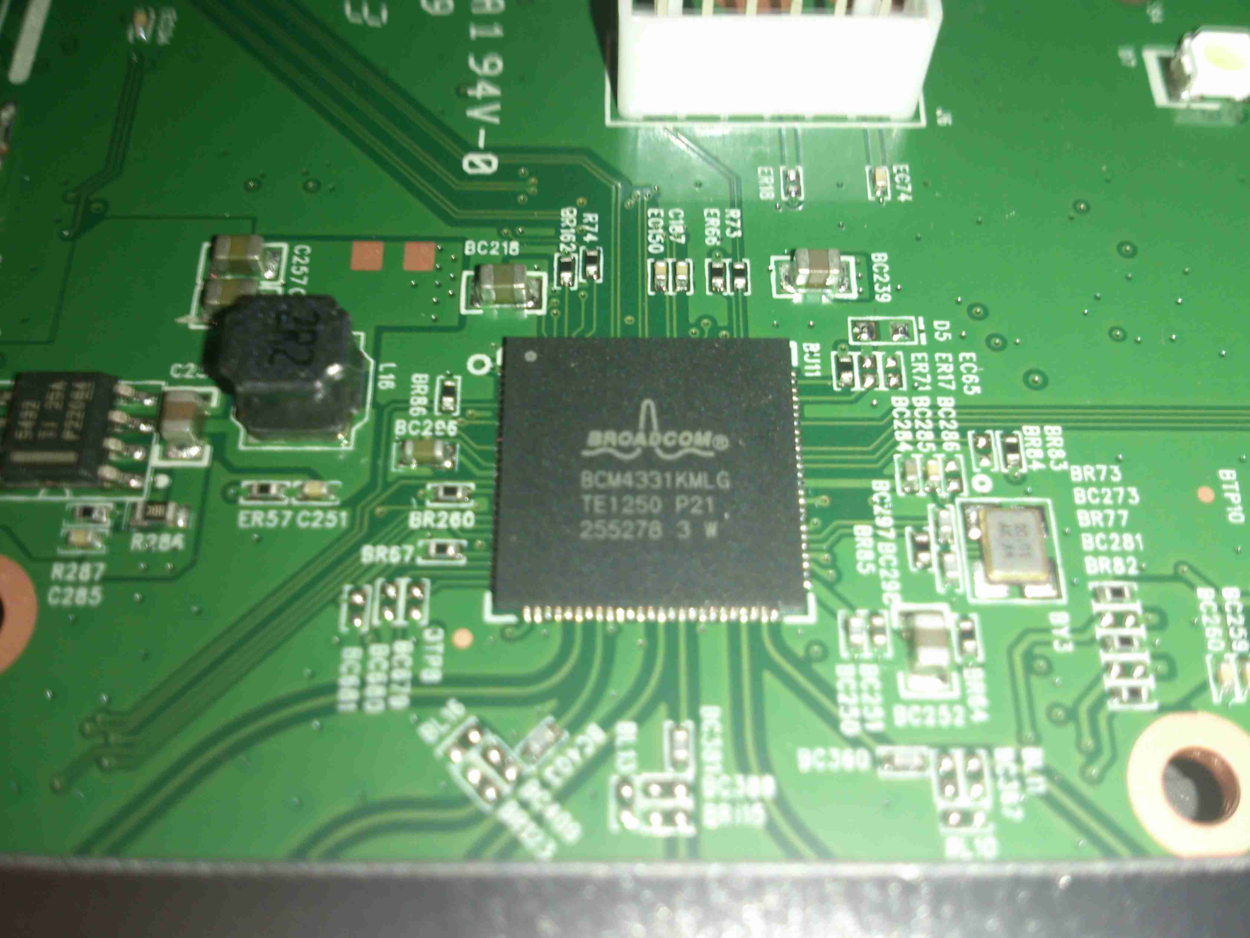
2.4GHz Transceiver
Wireless N is provided by a Broadcom BCM4331, this provides full dual-band 3×3 802.11n support. Being 3×3 it is actually 3 separate transceivers in a single package, to get much higher throughput rates of 600Mbit/s.
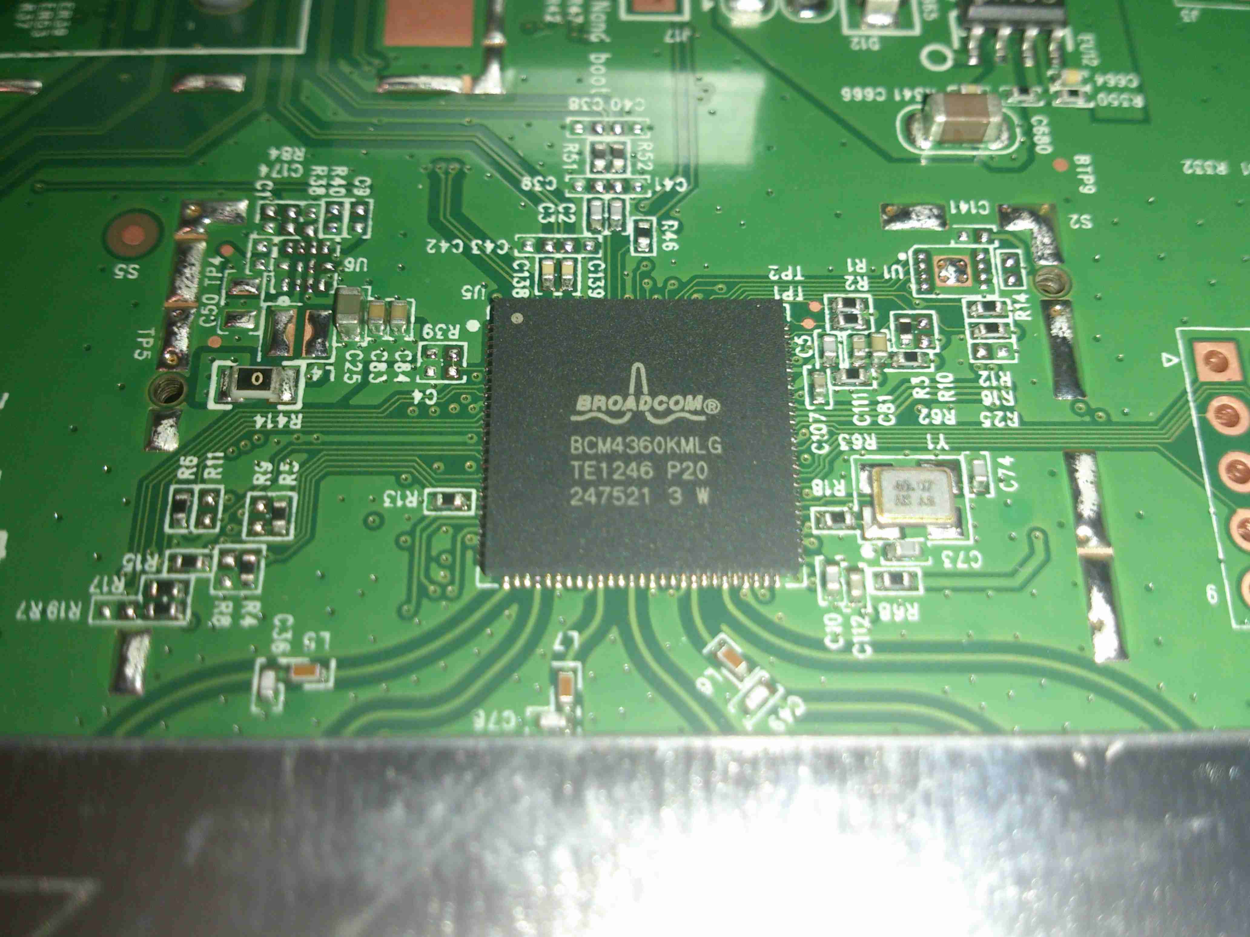
5GHz Transceiver
Wireless AC is provided by it’s sister IC, the BCM4360, with throughput speeds of 1.3Gbit/s. Both of these transceiver ICs connect back to the main CPU via PCI Express.
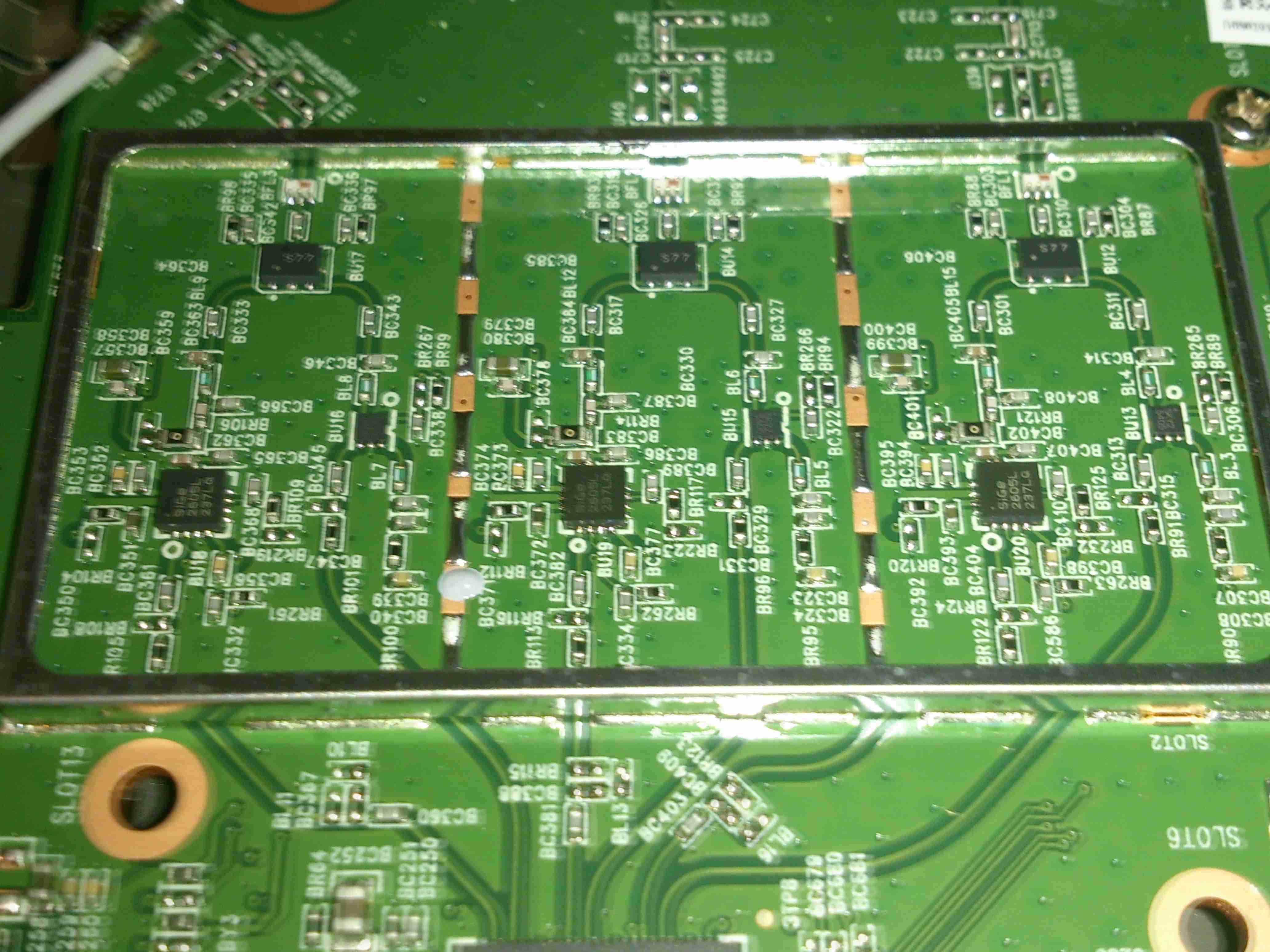
5GHz Power Amplifiers
To get increased range, there are a trio of Skyworks SE5003L +23dBm 5GHz power amplifier ICs under the shield, along with the TX/RX switching & antenna matching networks. Heatsinking for these is provided by a sink screwed to the bottom side of the PCB. The outputs to the antennas can be seen at the top of the image.
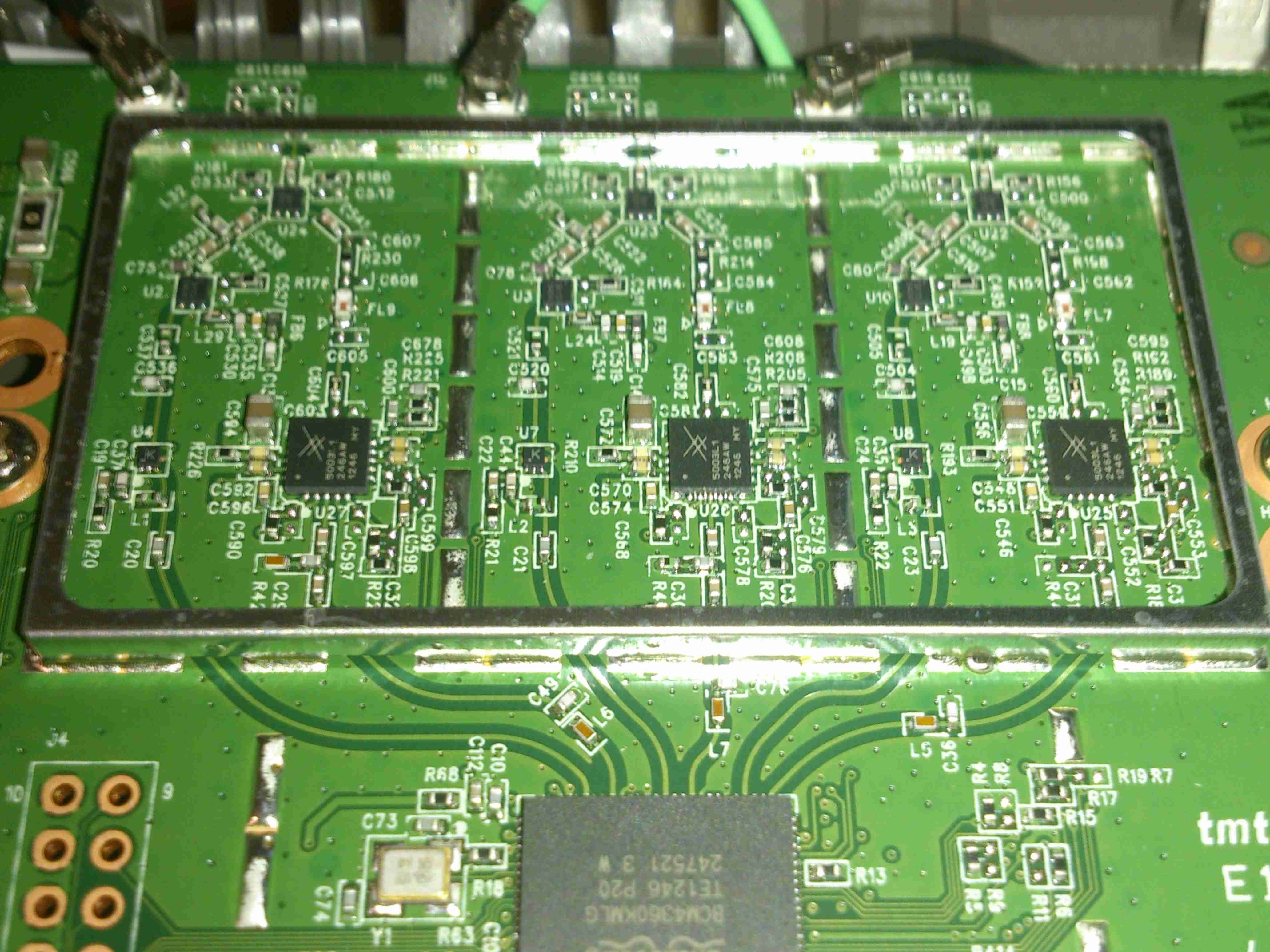
2.4GHz Power Amplifiers
The 2.4GHz section is fitted with a trio of Skyworks SE2605L +23dBm 2.4GHz power amplifiers, with a similar heatsink arrangement under the board. Unlike the 5GHz section, the 2.4GHz antenna feeds are soldered to the PCB here instead of using connectors.
Main CPU
The main CPU is a BCM4708 Communications Processor from Broadcom, as for the other Broadcom chips in this router, very little information is available unless under NDA, but I do know it’s a dual core ARM Cortex A9 running at 1GHz, with built in 5-port gigabit ethernet switch.
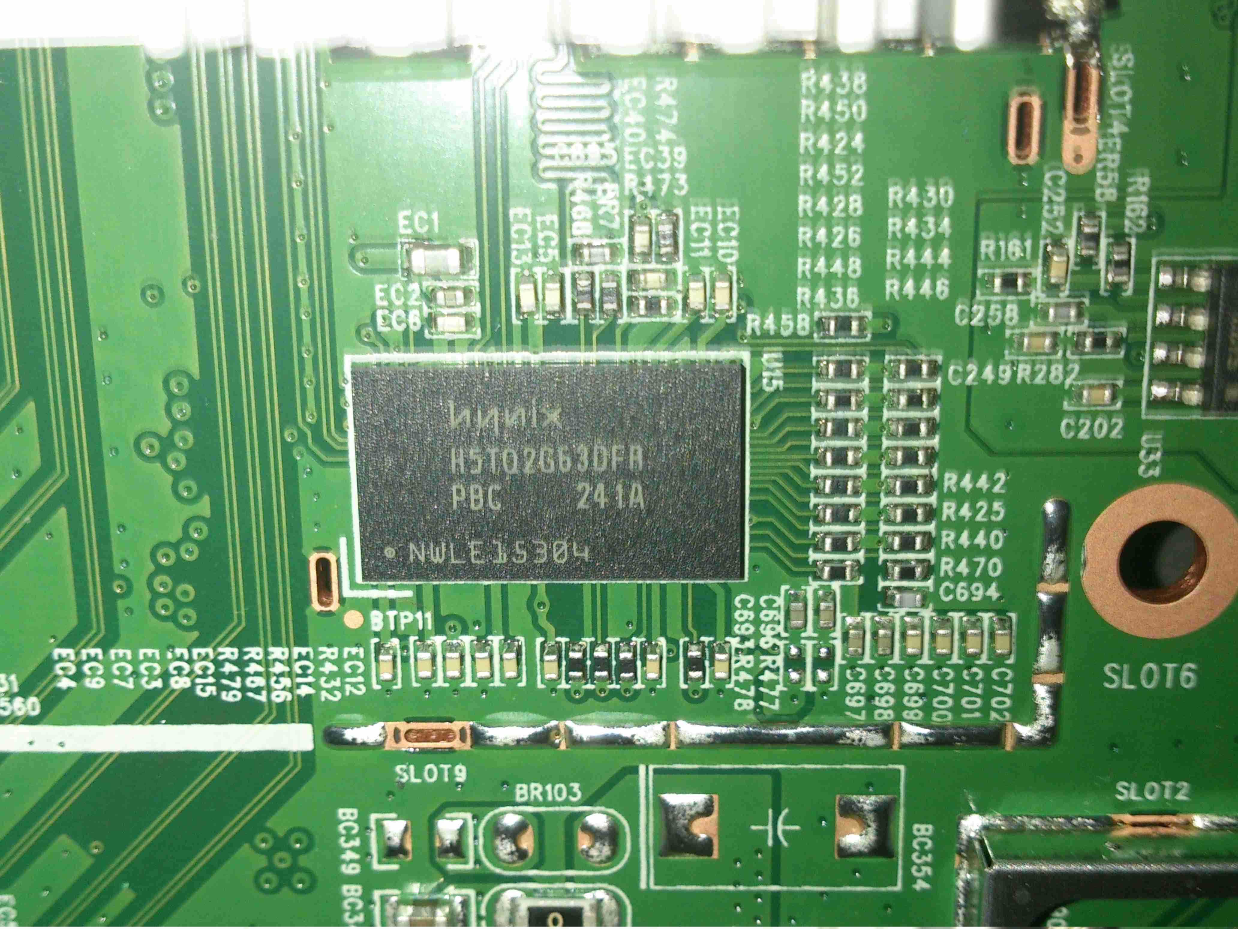
CPU RAM
Working RAM for the processor is a Hynix H5TQ2G63DFA 256MB part.
More to come on the installation of the new networking, with it’s associated 4G mobile gateway connection system.
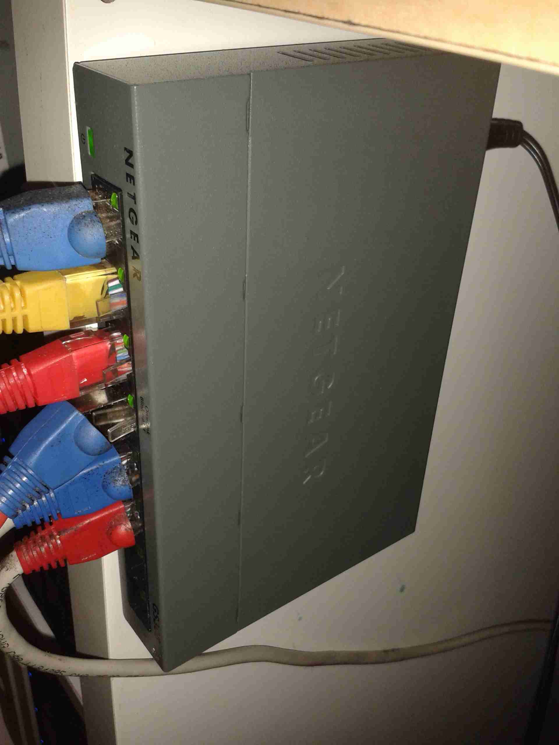
Here’s a new addition to the network, mainly to replace the ancient Cisco Catalyst 3500 XL 100MB switch I’ve been using for many years, until I can find a decently priced second hand commercial gigabit switch.
Operational
Here’s the switch with some network connections on test. So far it’s very stable & draws minimum power. I’ve not yet attempted to run my core links (NAS) through yet, as I’ve not yet seen a consumer grade switch that can stand up to constant full load without crashing.
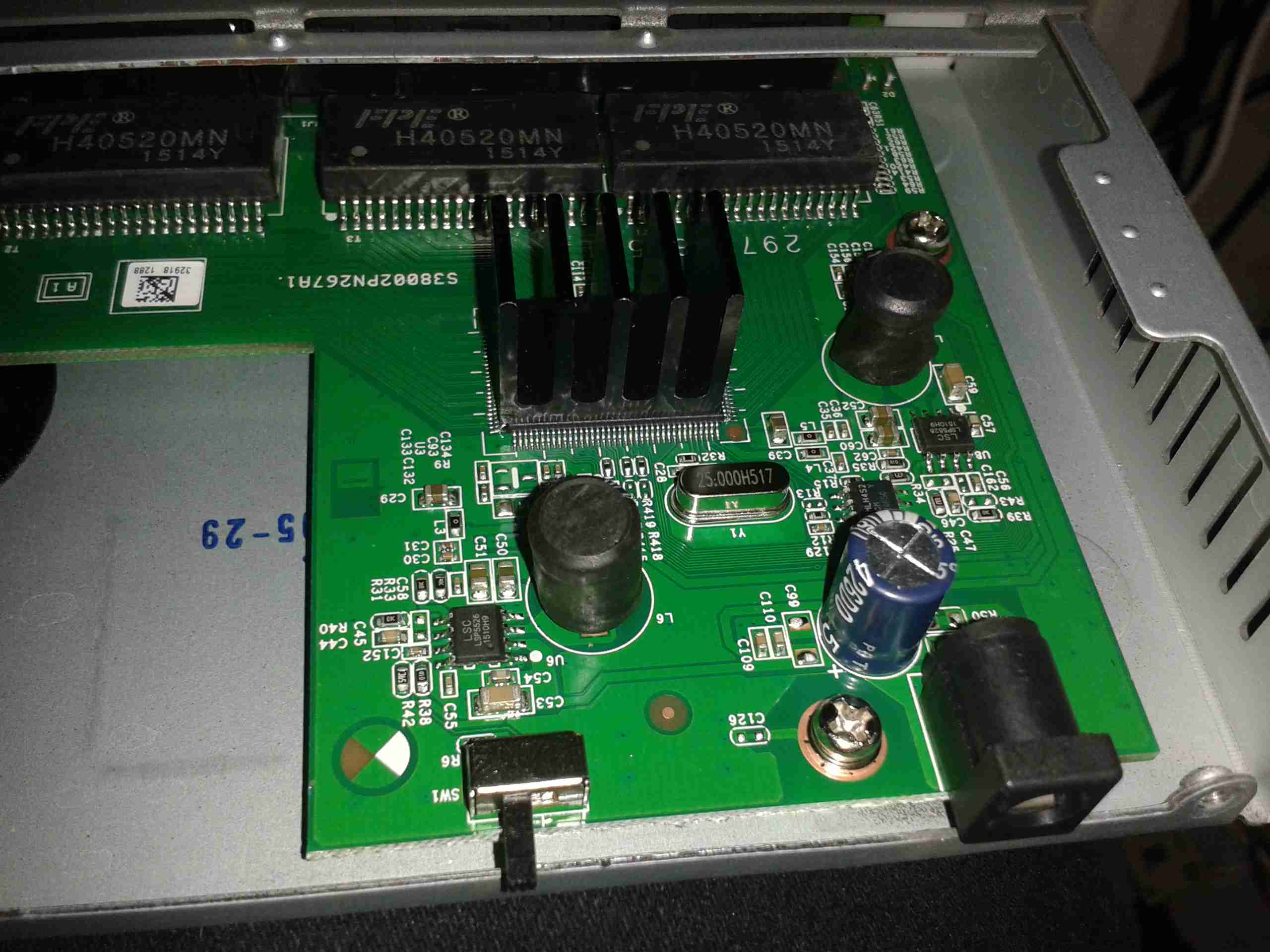
Internals
Here’s the switch with it’s lid popped. The magnetics can be seen at the back, next to the RJ-45 ports, the large IC in the centre is the main switching IC, with a heatsink bonded to the top. Very minimal design, with only a couple of switching regulators for power supply & not much else.
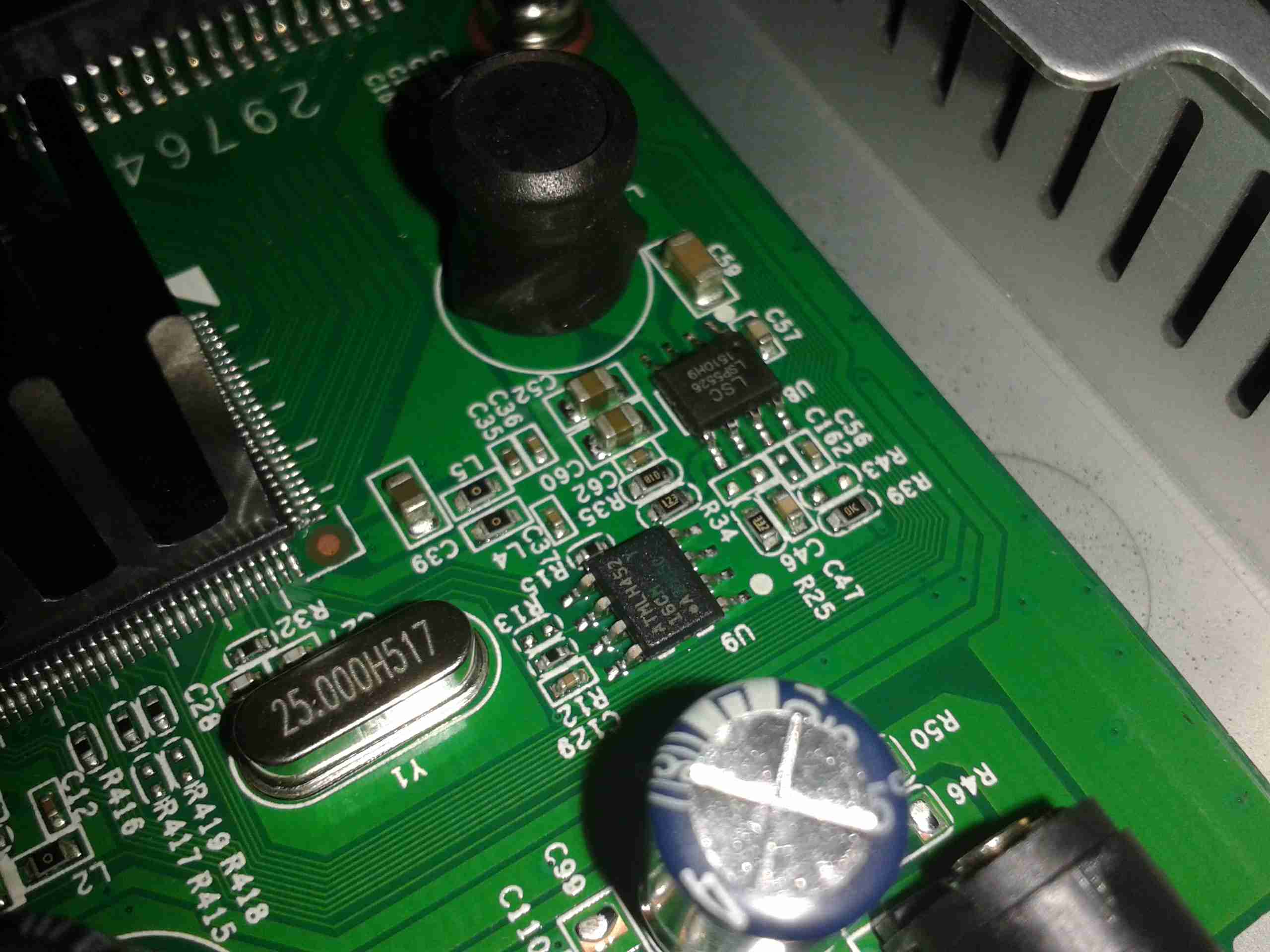
Power & EEPROM
Here’s a closeup of some of the support components. There’s a 25MHz crystal providing a clock signal for the switch IC, just to the right of that is an EEPROM. I imagine this is storing the switch configuration & MAC address. Further right is one of the switching DC-DC converter ICs for power.
As a quick test, here’s 500GB of data being shifted through the switch, at quite an impressive rate. I’m clearly maxing out the bandwidth of the link here. Soon I will upgrade to a 10G Ethernet link between the NAS & main PC to get some more performance.
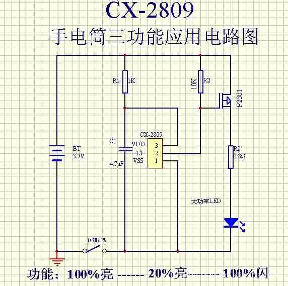
The multimode dimming/flashing modes on Chinese torches have irritated me for a while. If I buy a torch, it’s to illuminate something I’m doing, not to test if people around me have photosensitive epilepsy.
Looking at the PCB in the LED module of the torch, a couple of components are evident:
LED Driver PCB
There’s not much to this driver, it’s simply resistive for LED protection (the 4 resistors in a row at the bottom of the board).
The components at the top are the multimode circuitry. The SOT-23 IC on the left is a CX2809 LED Driver, with several modes. The SOT-23 on the right is a MOSFET, for switching the actual LED itself. I couldn’t find a datasheet for the IC itself, but I did find a schematic that seems to match up with what’s on the board.
Schematic
Here’s that schematic, the only thing that needs to be done to convert the torch to single mode ON/OFF at full brightness, is to bridge out that FET.
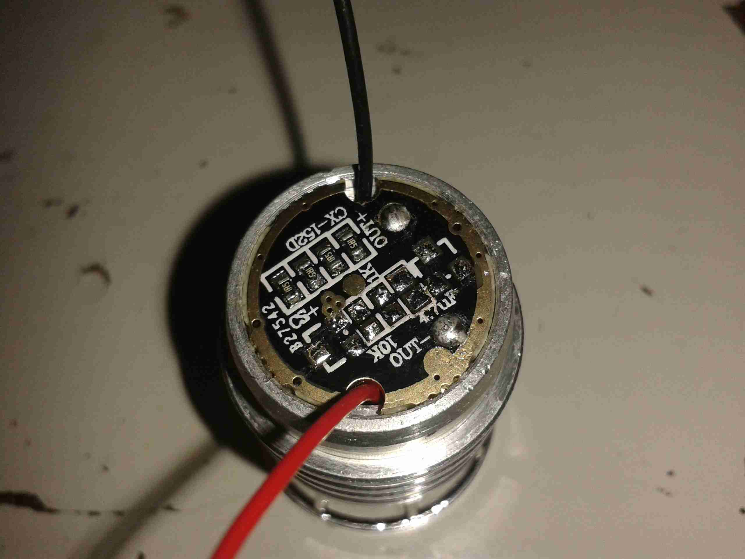
Components Desoldered
To help save the extra few mA the IC & associated circuitry will draw from the battery, I have removed all of the components involved in the multimode control. This leaves just the current limiting resistors for the LED itself.
Jumper Link
The final part above, is to install a small link across the Drain & Source pads of the FET. Now the switch controls the LED directly with no silly electronics in between. A proper torch at last.
Following on from the teardown & analysis of the charger, here’s the torch itself under the spotlight.
LED Torch
Here’s the torch itself, it’s a sturdy device, made of aluminium. Power is provided by a single 18650 Li-Ion cell.
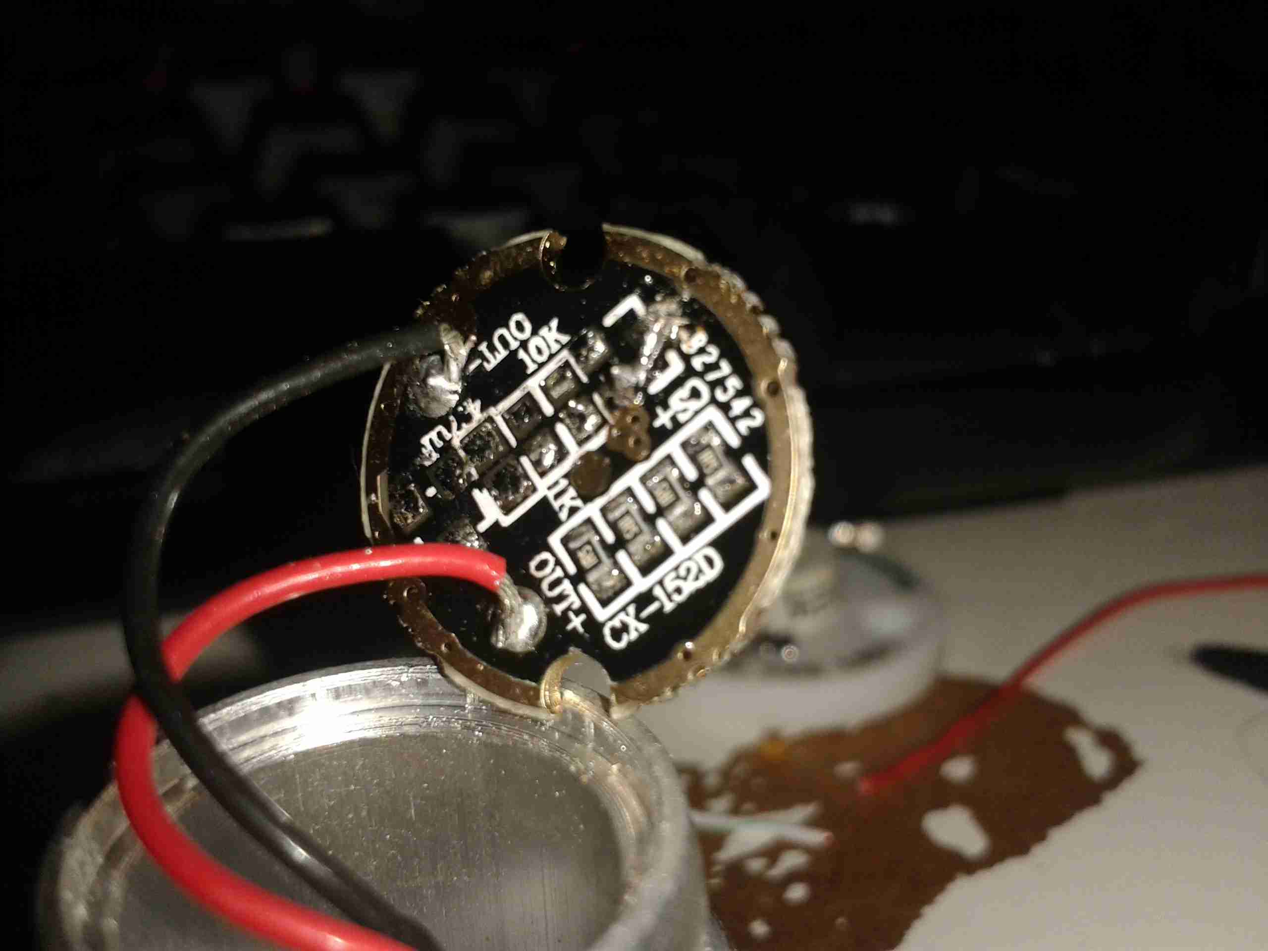
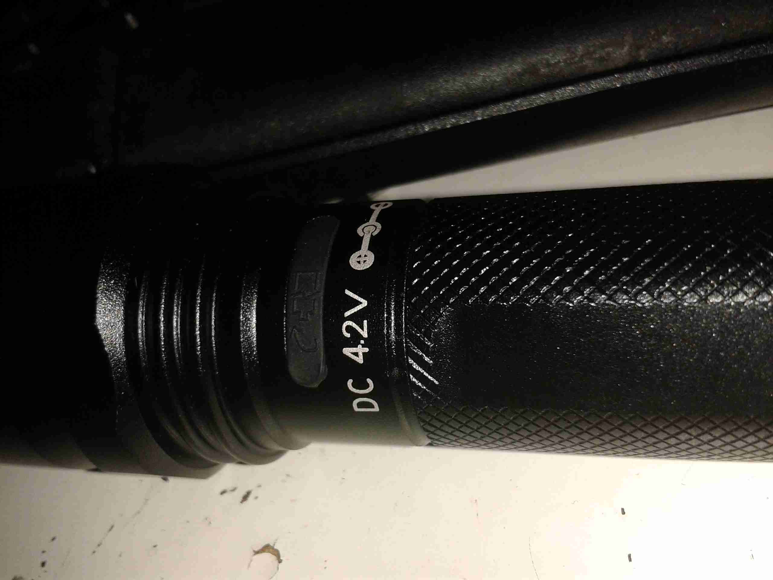
Charging Port
Here’s the charging port on the torch, there’s no electronics in here for controlling the charge, the socket is simply connected directly to the Li-Ion cell, and requires a proper external charger.
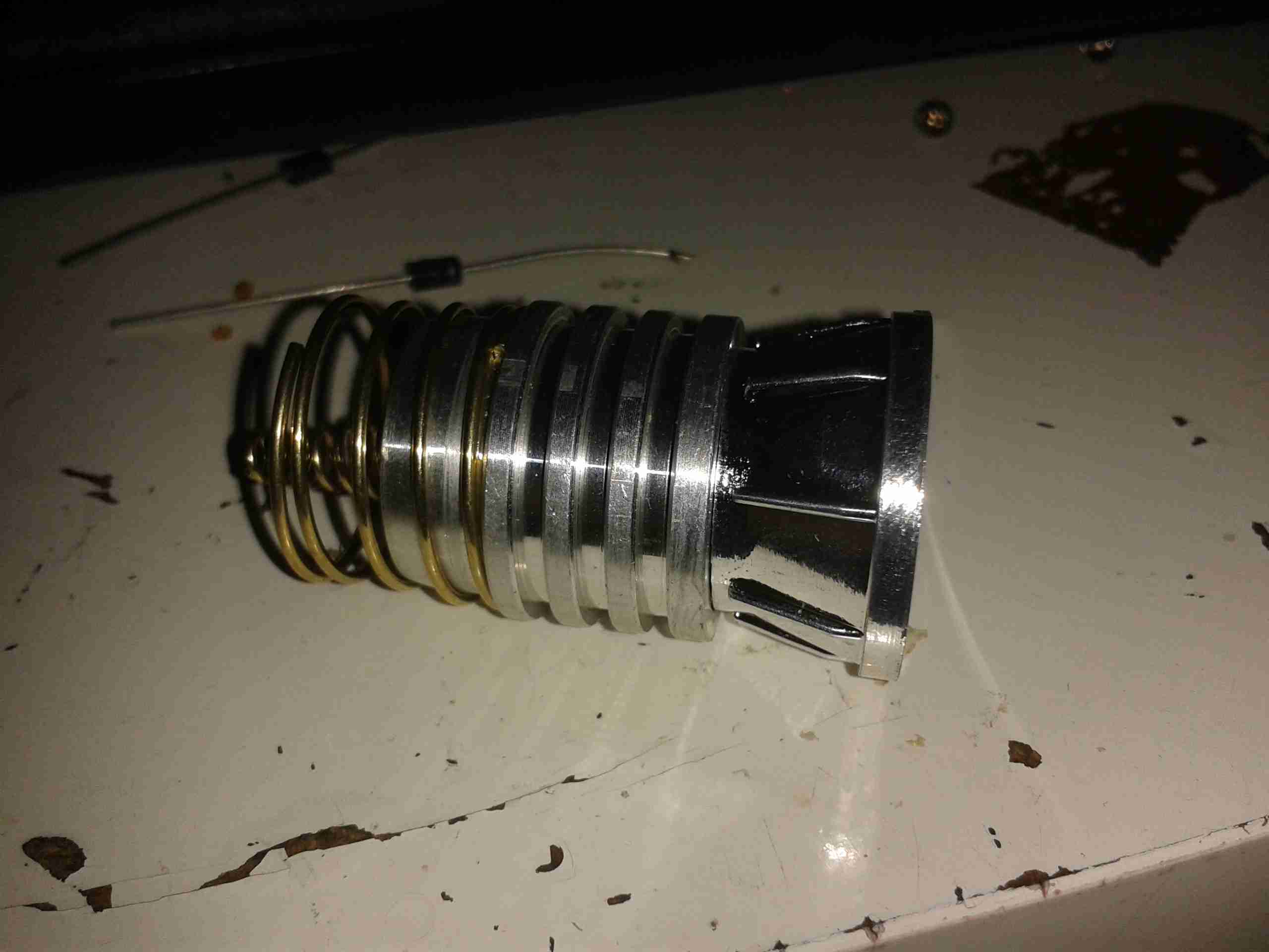
LED Pill
Unscrewing the lens gives access to the LED core, this also unscrews from the torch body itself, leaving the power switch & the battery in the body.
LED Module
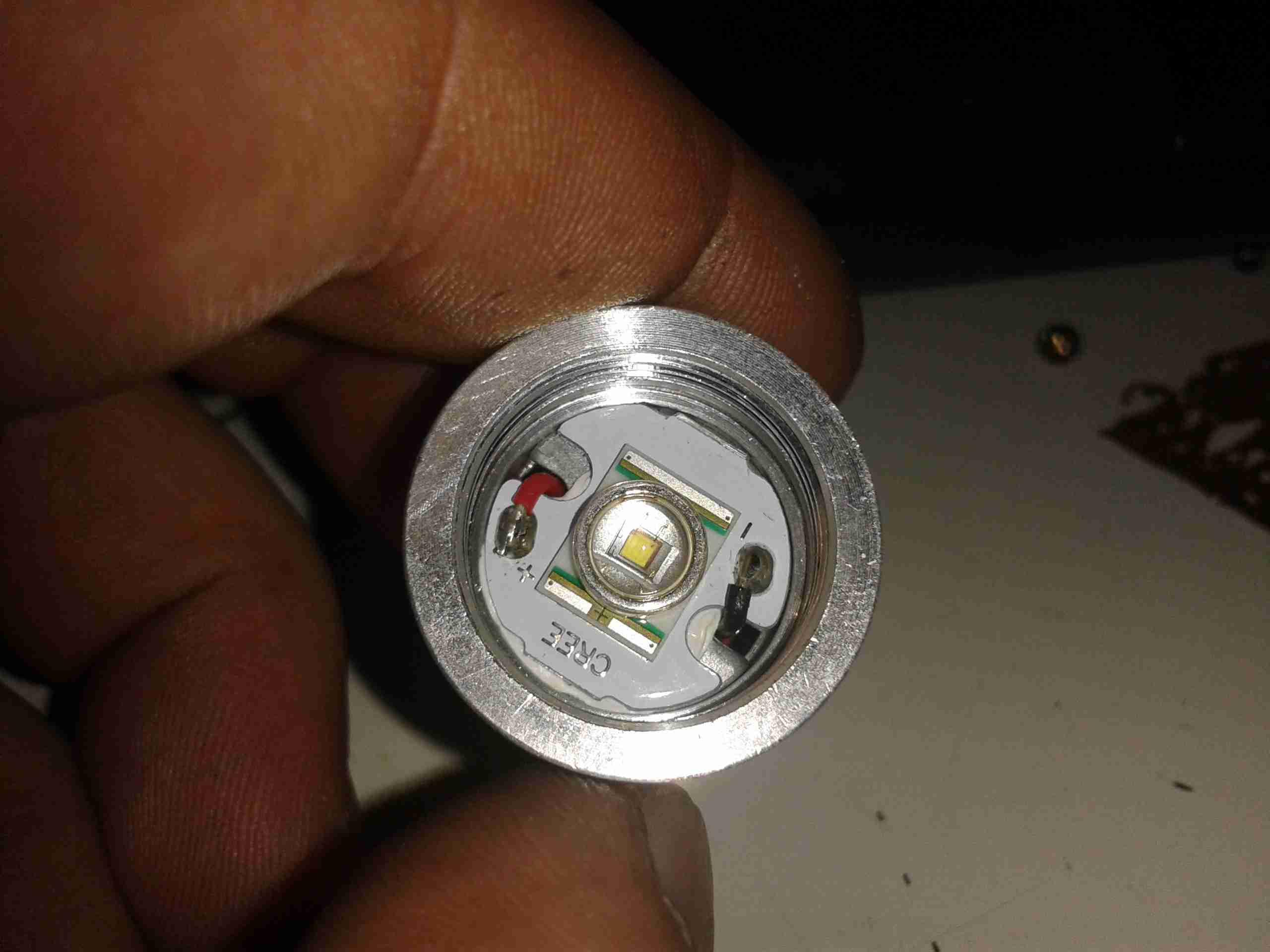
Unscrewing the aluminised plastic reflector reveals the LED itself. Being a new device, I expected an XM-L or XM-L2 Cree LED in here, but it’s actually an XR-E model, a significantly older technology, rated at max 1A of drive current.
LED Back
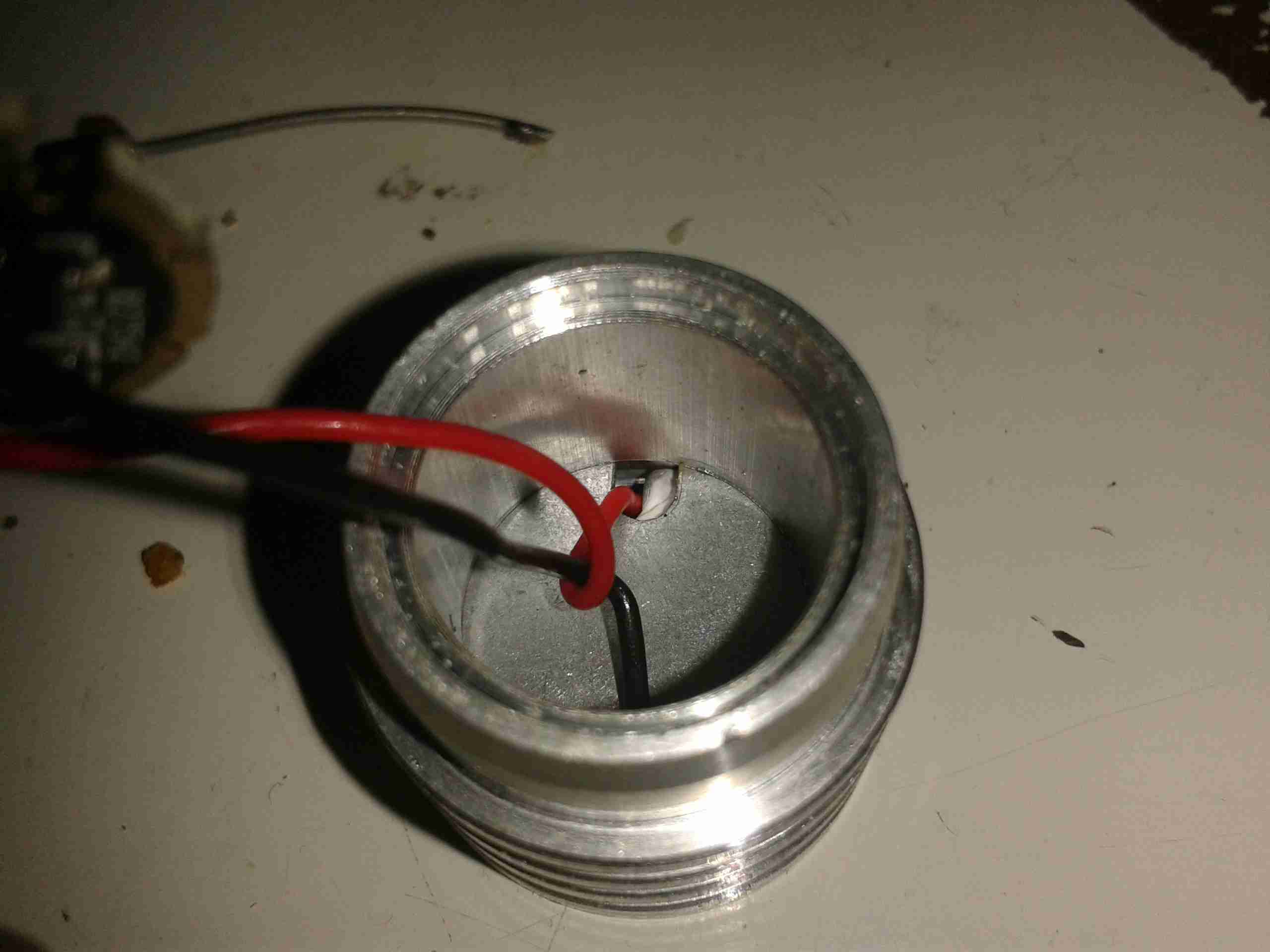
Popping the control PCB out from the pill reveals a lot of empty space, but the back of the LED is completely covered by a heatsinking plate, which is conducting heat to the main body of the torch.
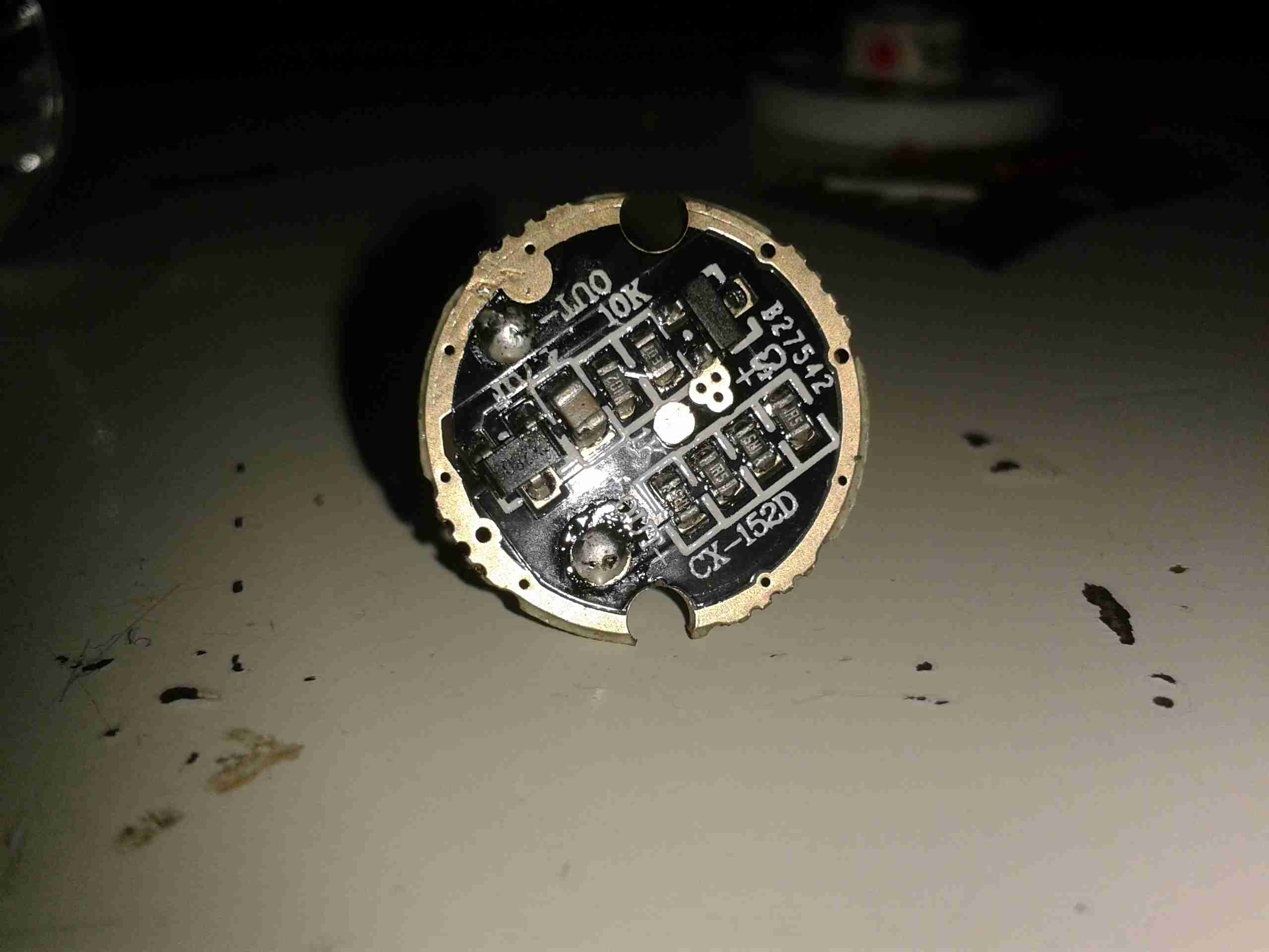
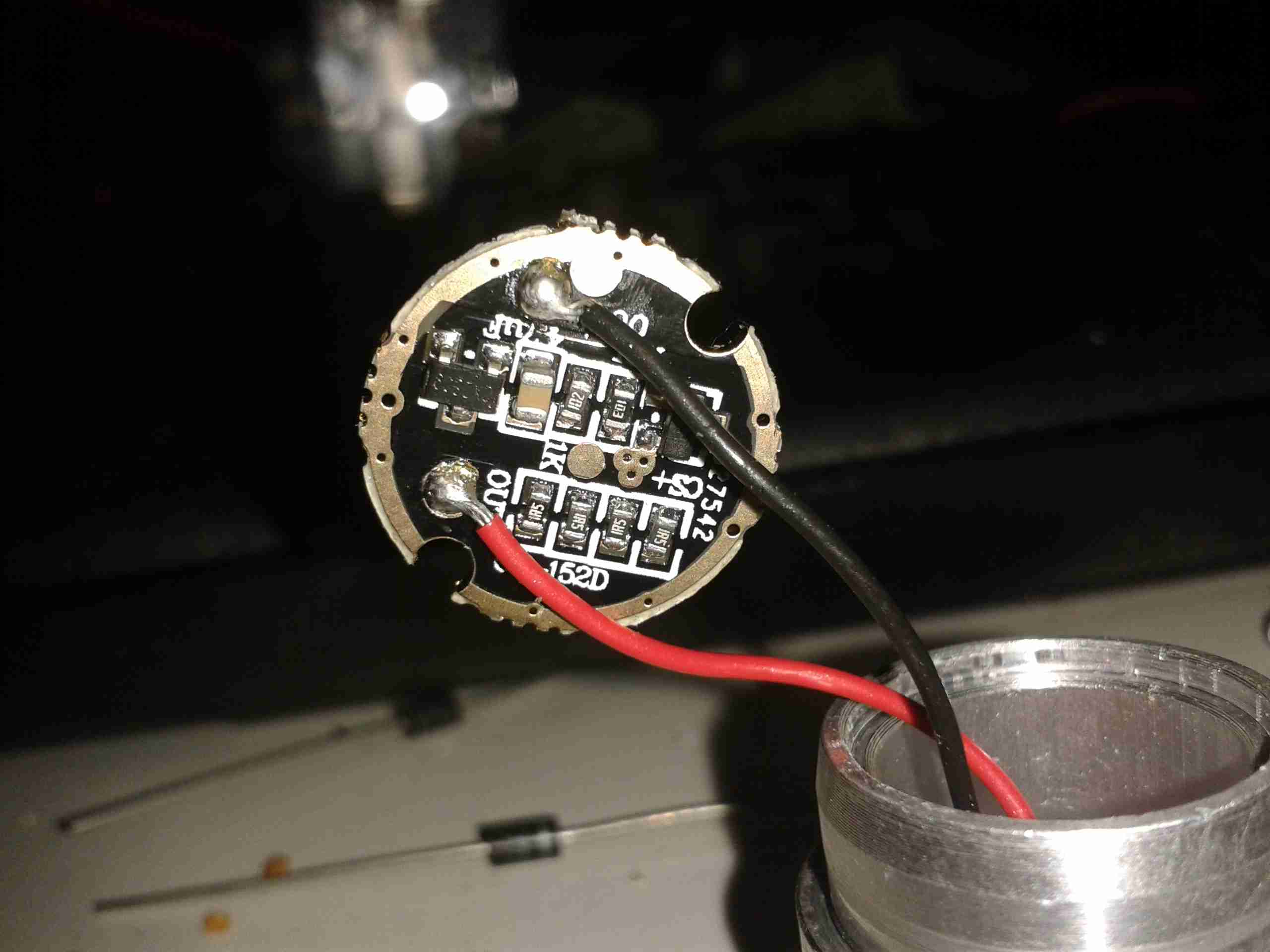
Control PCB
Not much to see on the control PCB, just a bunch of limiting resistors, and a multi-mode LED driver IC in a SOT-23 package. There’s no proper constant-current LED driver, and as the battery discharges the torch will dim, until the low voltage cutout on the cell turns things off completely.
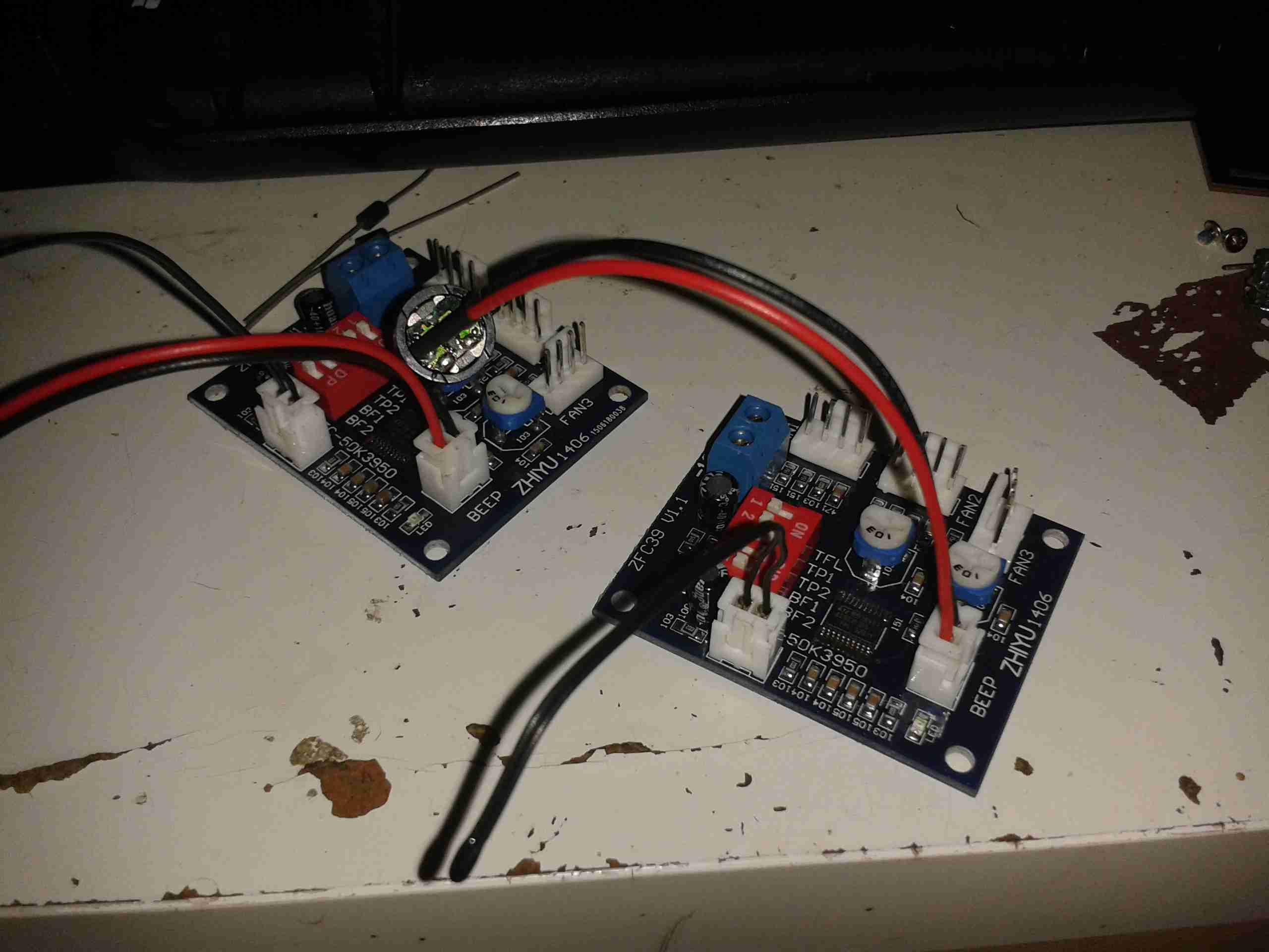
Finally, after a couple of weeks wait time, the fan controllers for the power supplies have arrived. They’re small boards, which is good for the small space left inside the case of the supply.
Controller Boards
Here they are. I’m not certain what the pair of potentiometers are for – there’s no mention of them in the documentation. Possibly for calibration.
Beepers are supplied so an alarm can be heard if the fan fails – very useful for this application.
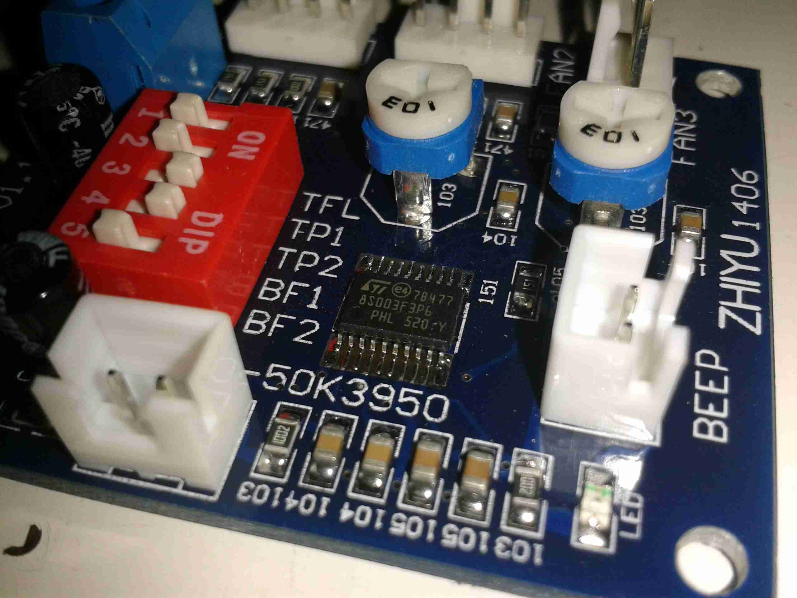
Controller Closeup
Here’s a closeup of the PCB. Options are set with the DIP switch bank on the left, details for that below. The main IC is a STM8S103F3 flash microcontroller.
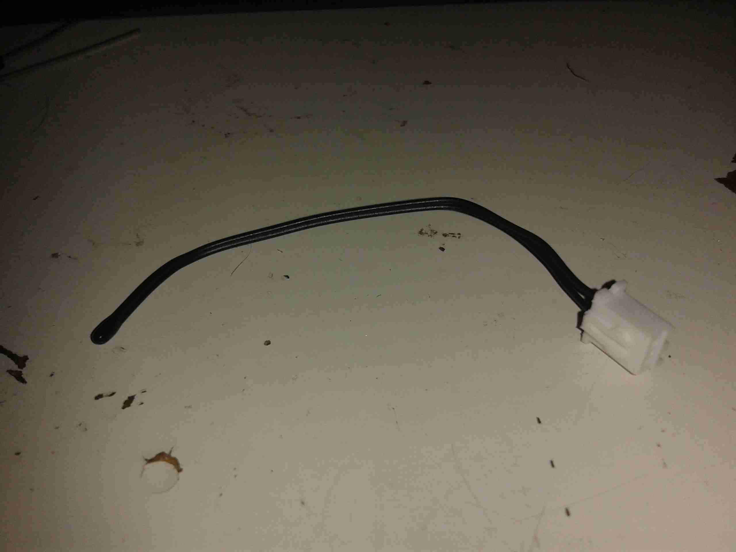
Temperature Probe
The only issue at the moment is that the temperature probe leads are much too short. I’ll have to make a small modification to get enough length here.
Here’s all the details on the boards, more for future reference when they undoubtedly vanish from eBay 😉
Specifications
Working voltage:DC12V
Circuit load capacity: maximum current per output 5A, the bus currents up 9A
Output Range: The first channel 20% -100%, or 40% -100% (TFL = ON)
The second channel and the third channel 10% -100%
(Note: Above range only for PWM range, the actual control effect will vary depending on the fan.)
Temperature probe parameters: 50K B = 3950
Thermostat temperature zone error: error depending on the temperature probe, generally 3-5%
Stall alarm minimum speed: 700-800 rpm
Function setting switch Description:
TFL (No. 1): The lowest temperature channel PWM setting, when ON state FAN1 PWM minimum is 40%, when OFF the minimum PWM of FAN1 is 20%.
TP1 TP2 (No. 2,3): Temperature channel control temperature zones are interpreted as follows (need to used with the temperature probe):
TP1
TP2
Accelerating temperature
Full speed temperature
OFF
OFF
35℃
45℃
ON
OFF
40℃
55℃
OFF
ON
50℃
70℃
ON
ON
60℃
90℃
When the temperature lower than the accelerated temperature, then output at the minimum rotation speed; when it exceed over the full temperature, then always output at full speed.
BF1 BF2 (No. 4,5): corresponds FAN1 FAN2 stall alarm function switch, when the corresponding open channel fan break down, the controller will alarm with soundand light (works with buzzle), alarm will automatically eliminated when the fan is rotated recovery . If BF1 and BF2 both are open (ON), the FAN1, FAN2 have any one or both stops, the controller will alarm!
A while back I posted about a 3M Touch Systems industrial monitor that I’d been given. I had previously paired it with a Raspberry Pi Model B+, but for general desktop use it was just a little on the slow side.
Since the release of the Raspberry Pi 2, with it’s 4-core ARM Cortex CPU, things are much improved, so I figured I’d post an update with the latest on the system.
The monitor I’ve used is a commercial one, used in such things as POS terminals, service kiosks, etc. It’s a fairly old unit, but it’s built like a tank.
3M Panel
It’s built around a Samsung LTM170EI-A01 System-On-Panel, these are unusual in that all the control electronics & backlighting are built into the panel itself, instead of requiring an external converter board to take VGA to the required LVDS that LCD panels use for their interface.
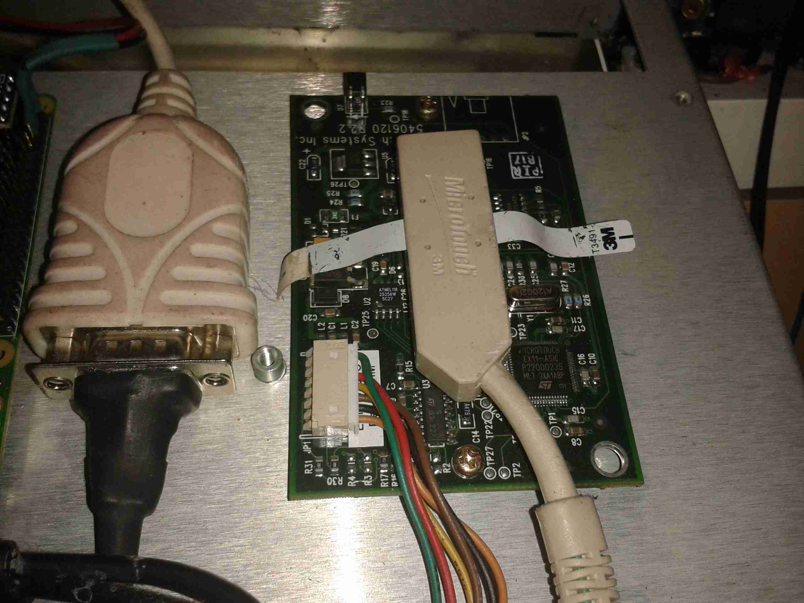
The touch section is a 3M Microtouch EXII series controller, with a surface capacitive touch overlay.
Touch Controller
Above is the touch controller PCB, with it’s USB-Serial converter to interface with the Pi.
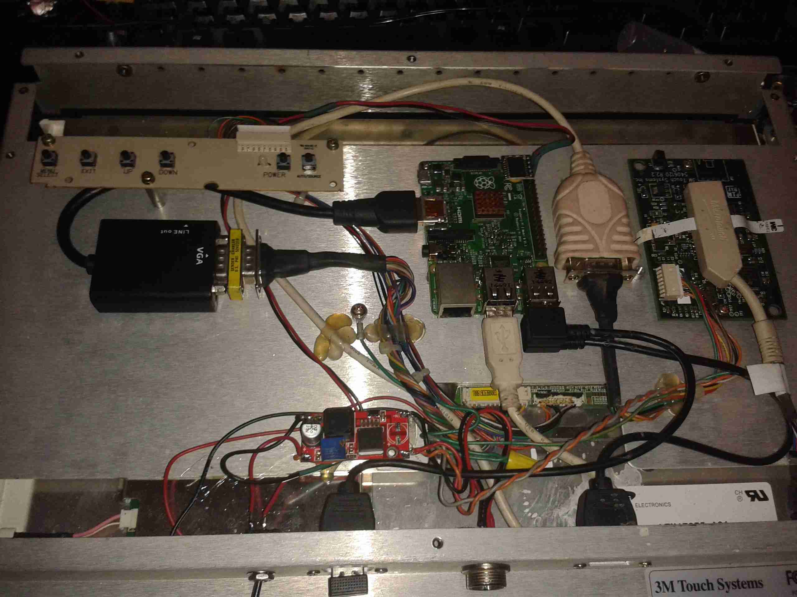
As there is much spare space inside the back of this monitor, I have mounted the Pi on a couple of spare screw posts, fitted USB ports where the original VGA & Serial connectors were in the casing, and added voltage regulation to provide the Pi with it’s required 5v.
Overview
Here’s the entire back of the panel, the Pi in the middle interfaces with a HDMI-VGA adaptor for the monitor, and the serial adaptor on the right for the touch. A small voltage regulator at the bottom of the unit is providing the 5v rail. There’s a switch at the bottom next to one of the USB ports to control power to the Pi itself. The panel won’t detect the resolution properly if they’re both powered on at the same time.
At 13.8v, the device pulls about 2A from the supply, which seems to be typical for a CCFL backlighted LCD.
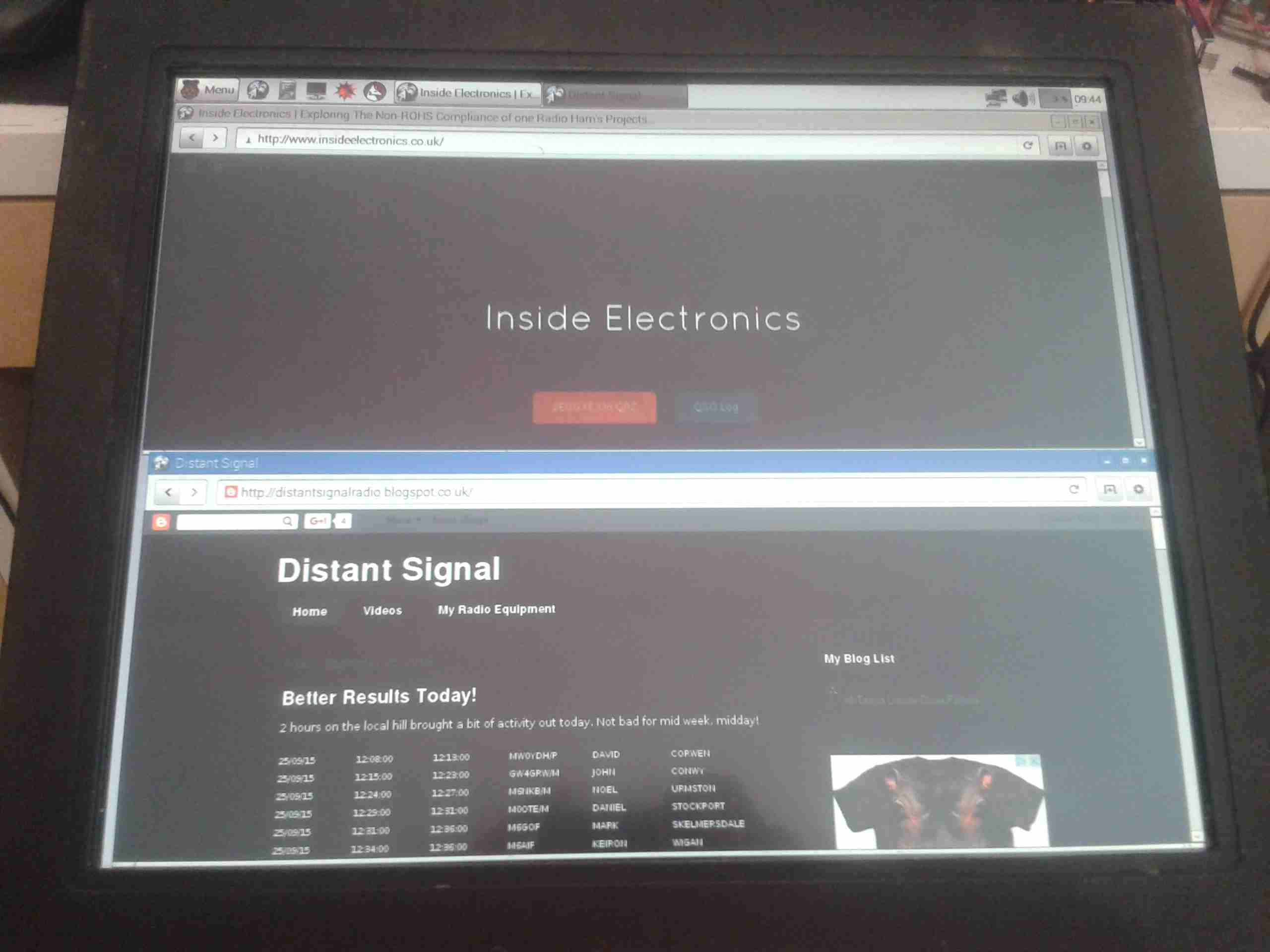
Now the Raspberry Pi 2 has been released, it’s much more responsive for desktop applications, especially with a slight overclock.
Shameless Plug
A full disk image enabled for Desktop & 3M touch monitors is available below for others that have similar panels. This image only works for the Pi 2!
Following on from my recent power supply build, I’ve added on a couple of improvements:
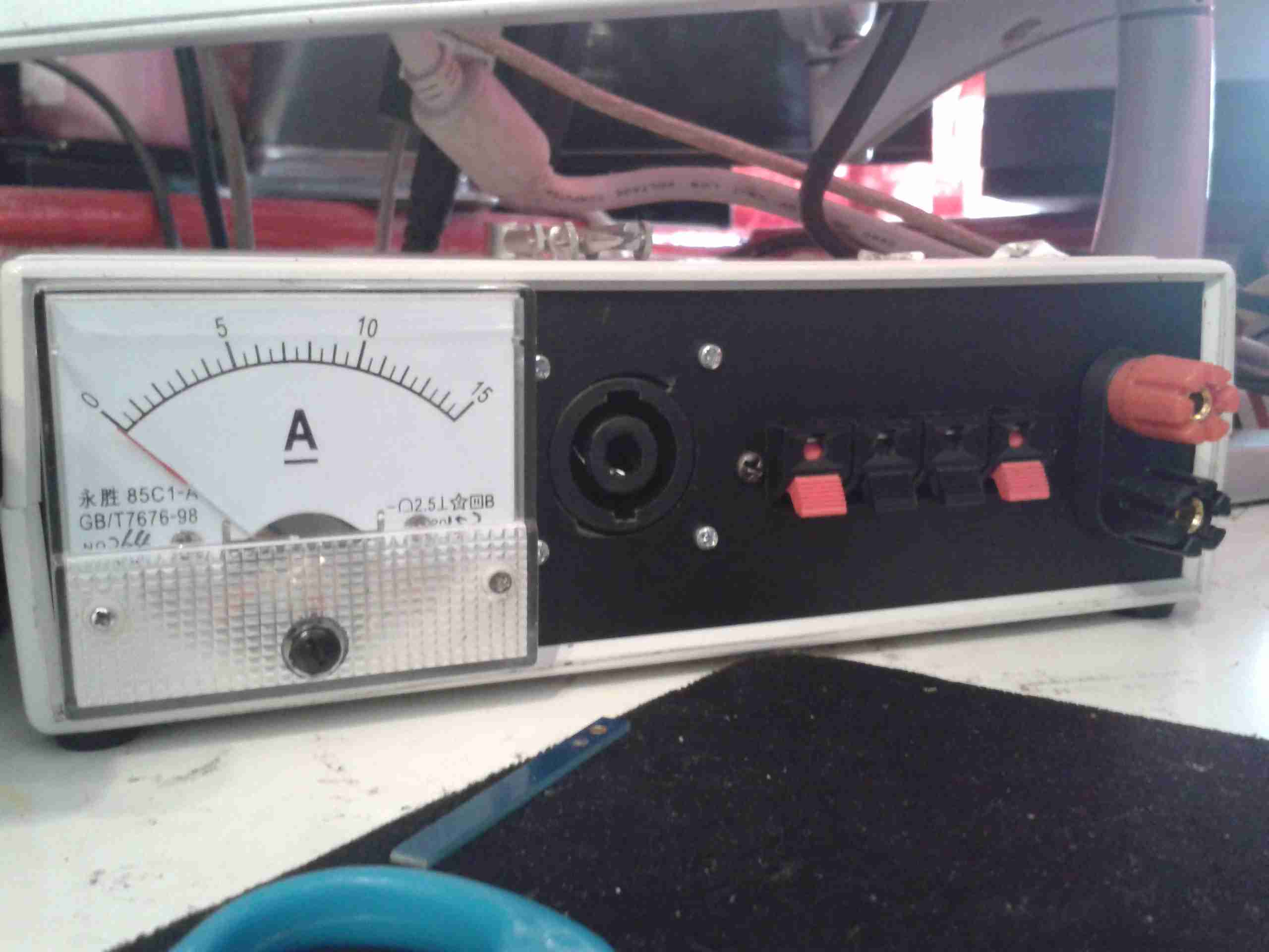
Front Panel
I’ve added on my standard SpeakOn type 30A connector, a bank of push terminals for quick connecting test leads, and a 15A FSD ammeter.
Panel Rear
Due to the limited space inside the supply, I’ve had to improvise some insulation on the mains-side heatsink to prevent a nasty accident. The heatsinks are tied to the supply’s HVDC bus negative, so they are energized at -145v DC relative to mains earth. This fact has given me a nasty surprise! The insulation is several layers of Kapton tape, with a couple of layers of Duct Tape. This along with trirated wire to the SpeakOn & the panel meter should ensure safety.
The Ammeter itself was sourced from eBay, for £2. It seems pretty accurate so far!
Ammeter
The shunt is built into the rear of these meters, in an ultrasonically welded part of the case, so I can’t examine it. Hopefully it is indeed rated to 15A!
The only things left to make this supply complete are a mains power switch, and a fan speed control, as the fan I have used is a little noisy at full speed. It will be good to get the speed based from the internal temperature, so the fan only runs at full speed when the supply is under load.
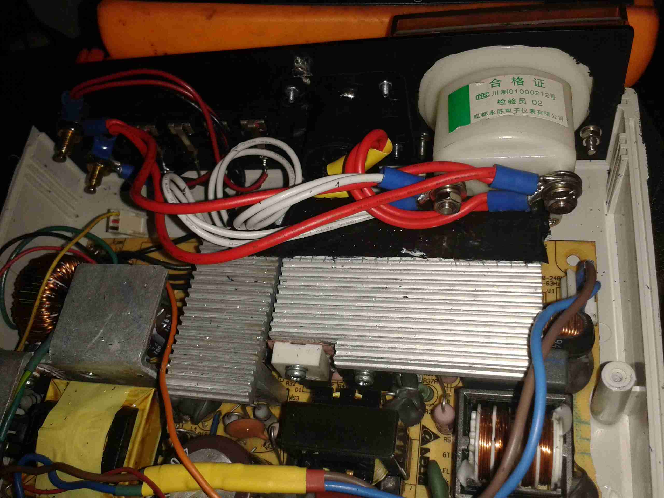
Now the final bits have arrived for the SWR Meter module, I can do the final assembly.
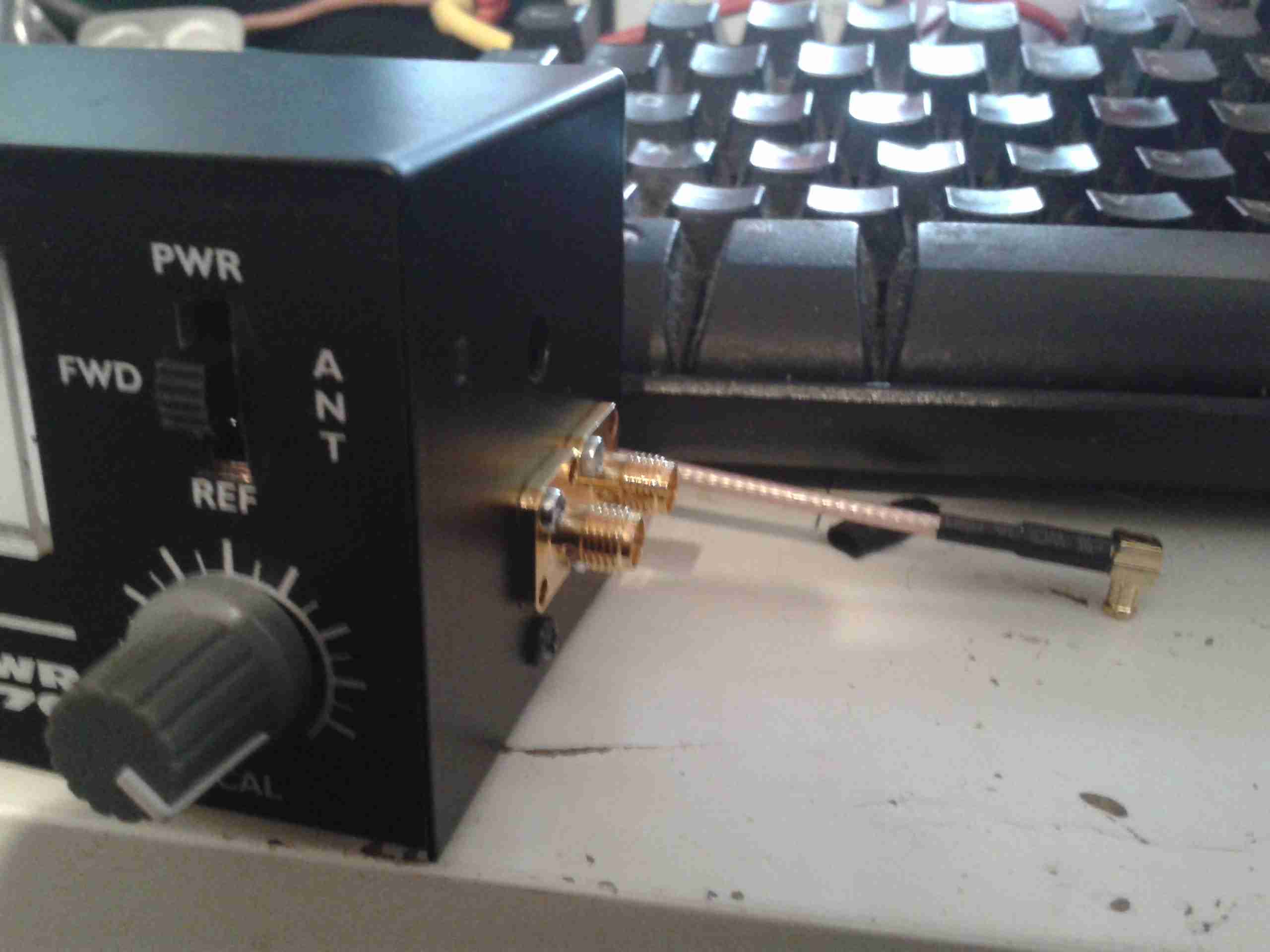
SMA Connectors
Here the SMA connectors are installed on the side of the eBay meter, for forward & reverse power tap.
These are simply tee’d off the wiring inside the meter where it connects to the switch.
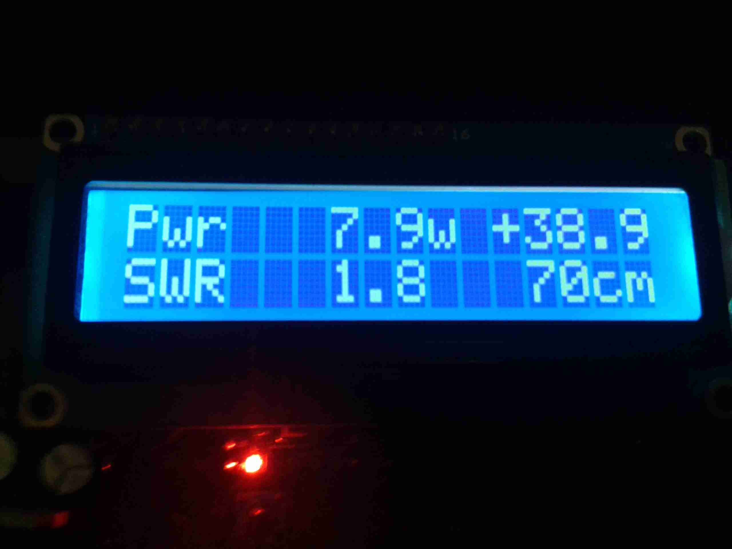
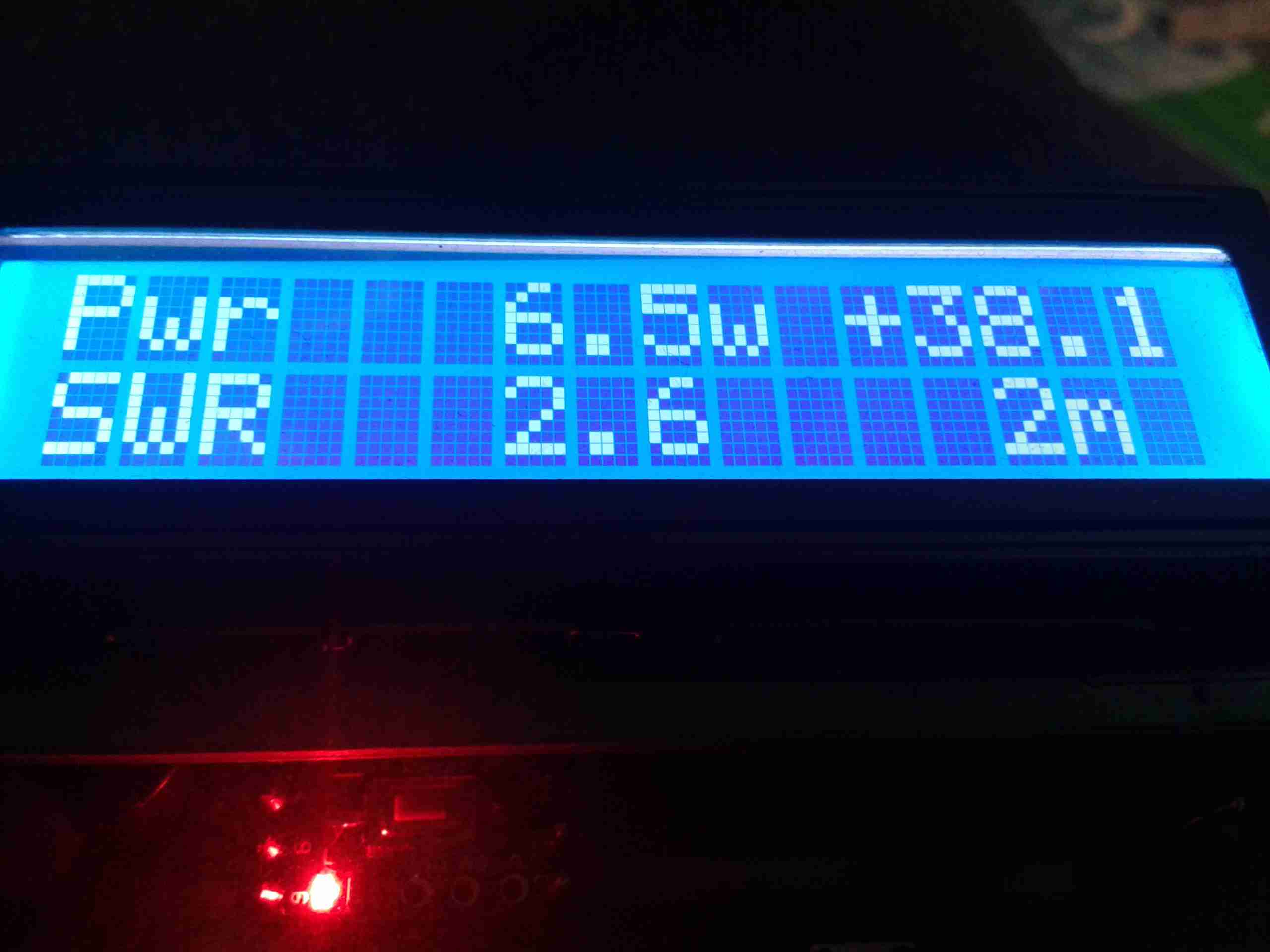
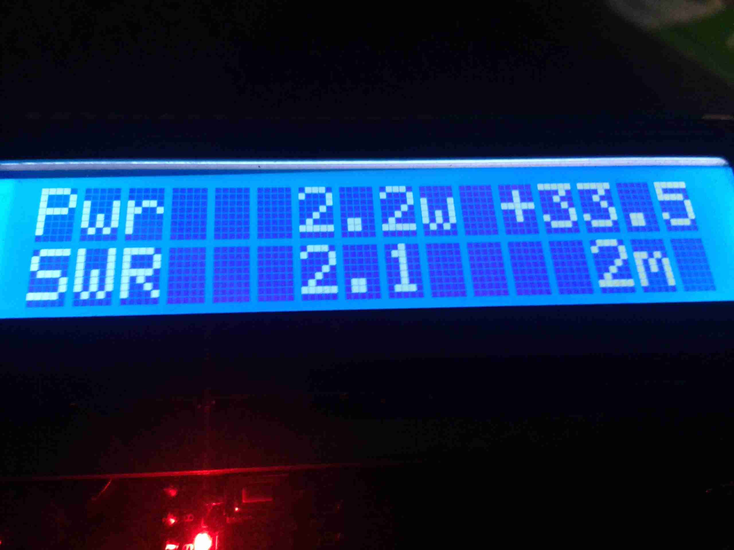
Uncalibrated
The meter is connected to the module via a pair of RG58 SMA leads, above is a readout before calibration, using one of my Baofeng UV-5Rs.
I’m using my GY561 eBay Power Meter as a calibration source, and as this isn’t perfect, the readings will be slightly off. If I can get my hands on an accurate power meter & dummy load I can always recalibrate.
Tools are only as accurate as the standard they were calibrated from!
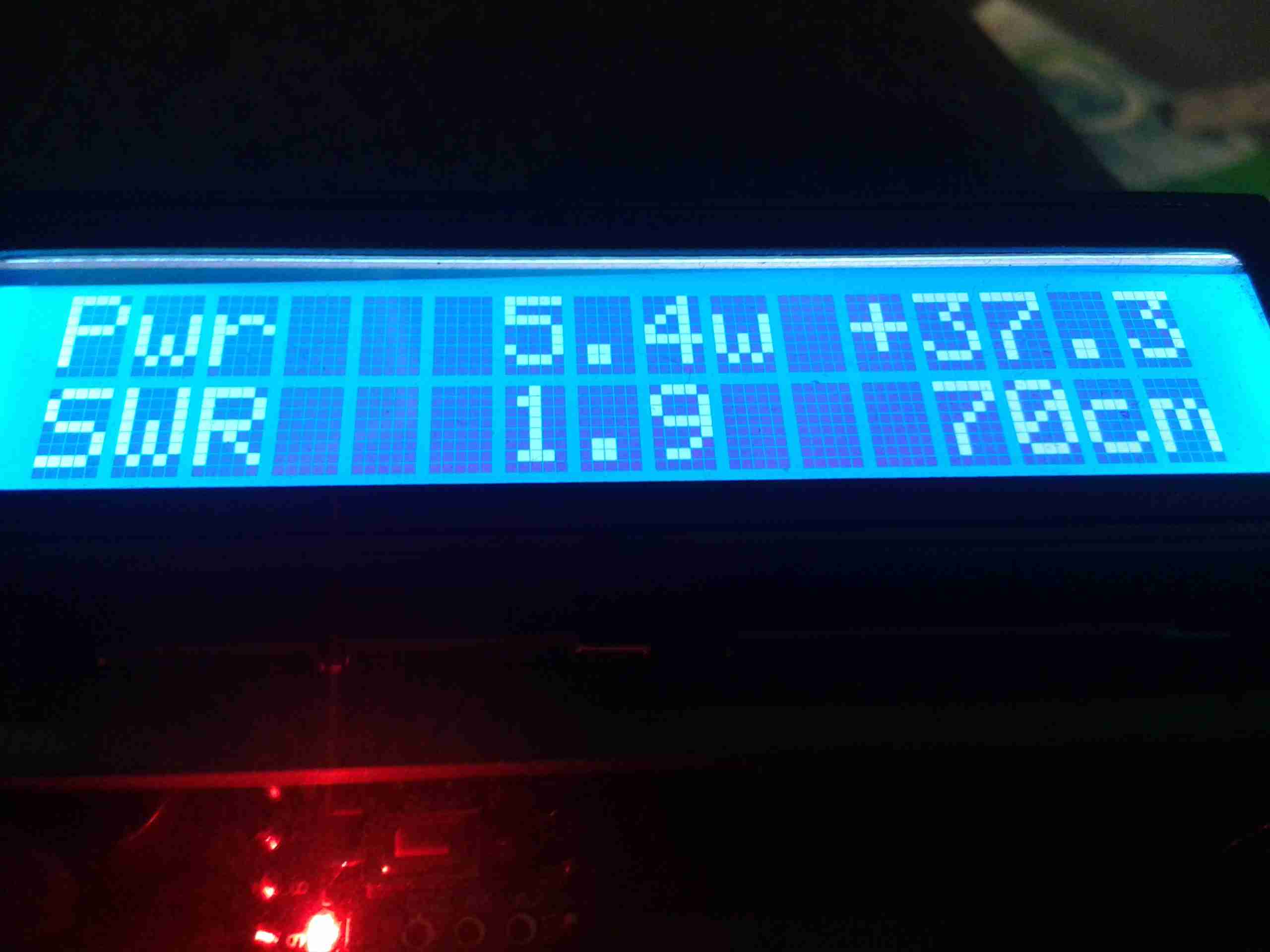
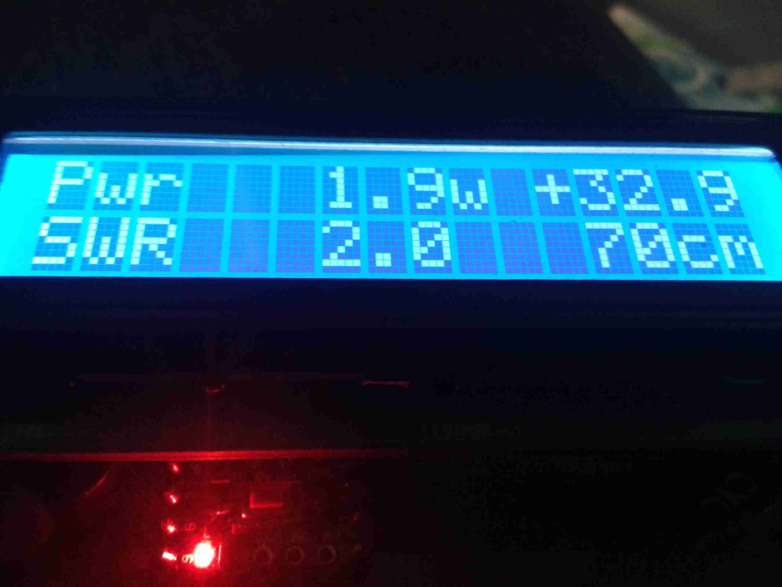
After calibration, here’s the readings on 2m & 70cm. These readings coincide nicely with the readings the GY561 produce, to within a couple tenths of a watt. SWR is more than 1:1 as the dummy load in the GY561 isn’t exactly 50Ω.
High Power VHFLow Power VHFHigh Power UHFLow Power UHF
Shortly I’ll calibrate against 6m & 10m so I can use it on every band I have access to 🙂
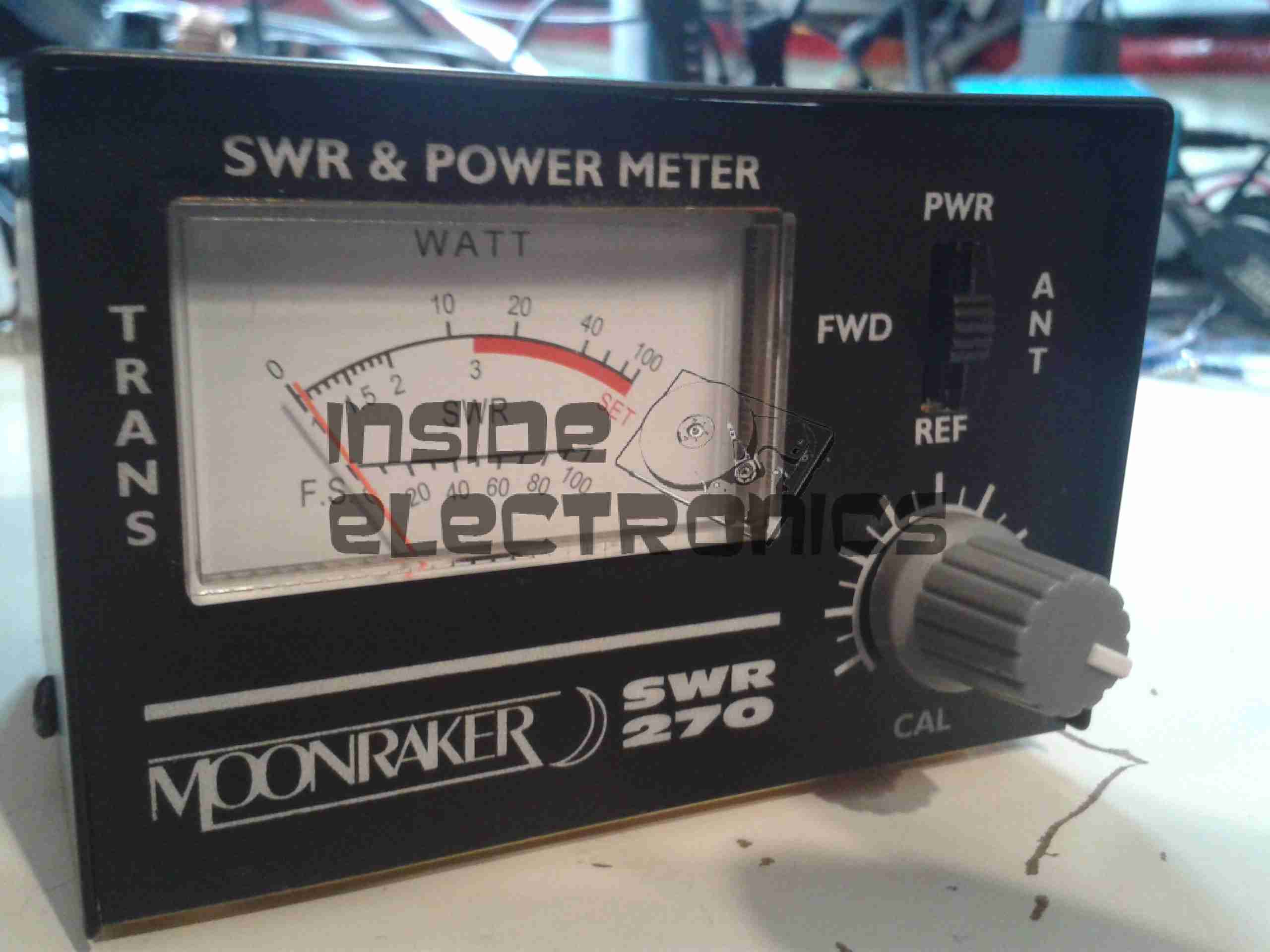
As I’m building up my radio shack, I figured an SWR meter would be a handy addition to my arsenal. This is a cheap Moonraker brand meter, which also will measure RF power. Above the front of the meter is shown, with the moving coil meter movement on the left, calibration adjustment on the right & the forward/reverse power switch.
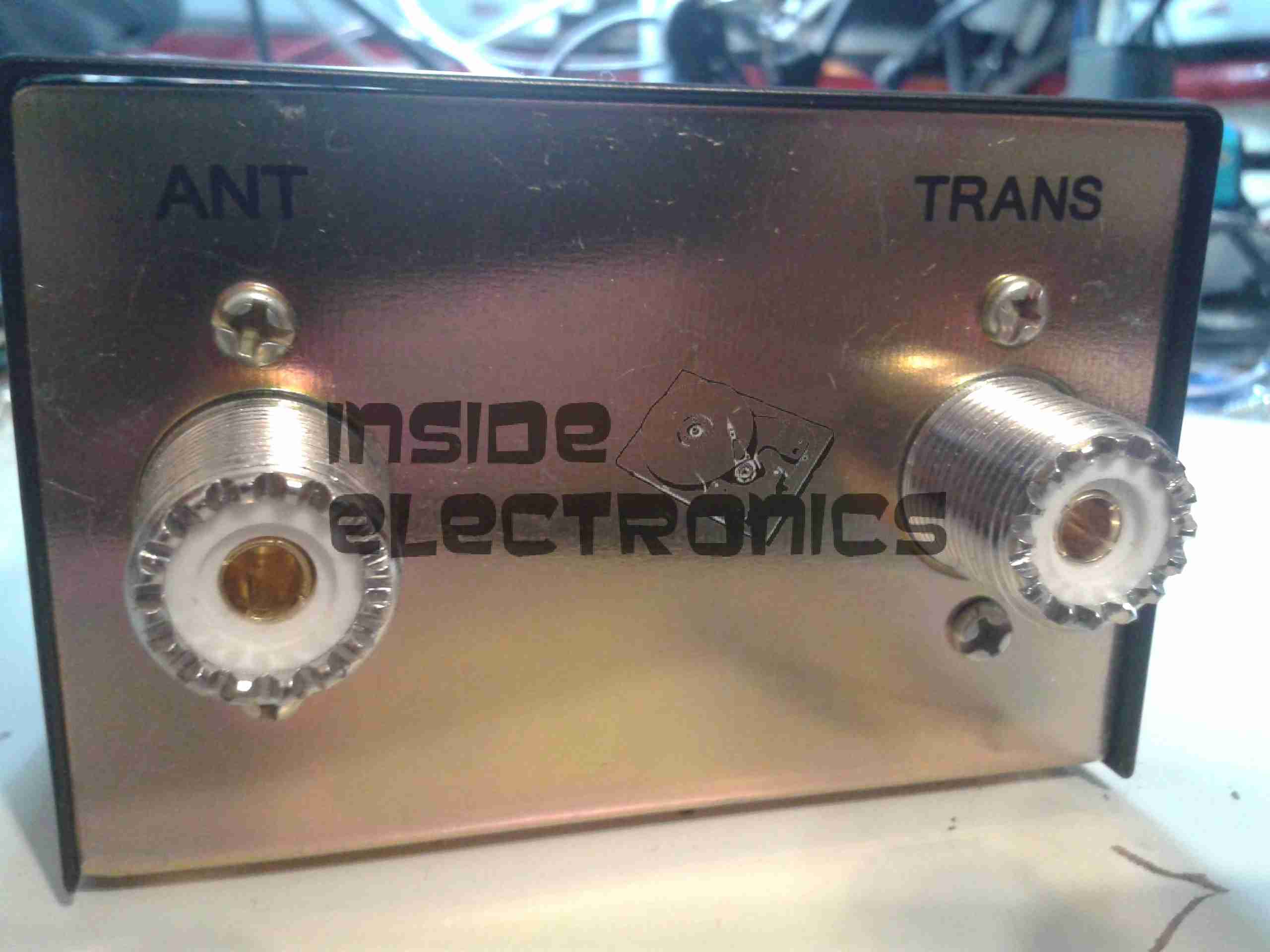
Meter Rear
For connections, standard SO-259 jacks are provided. The casing is sturdy 1mm steel. This is good, considering it’ll probably take a beating in my portable radio bag.
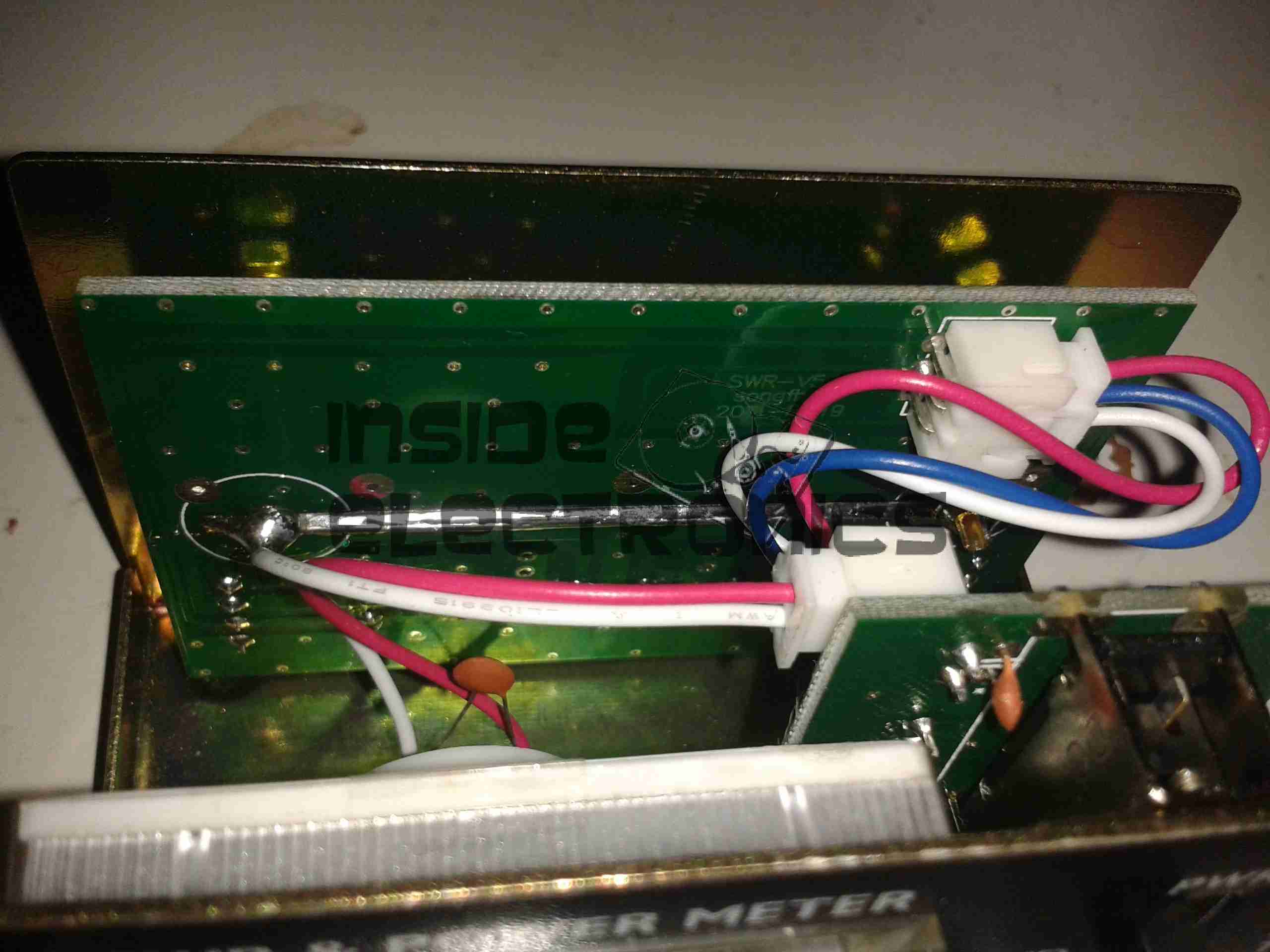
Directional Coupler PCB
Here the cover is removed, showing some of the internals. The large PCB across the back is the directional coupler.
Directional Coupler Circuit
The SO-259 connectors are bridged with a transmission line, (the track covered in solder in the image below), while there are a pair of sense lines running alongside. This main line is electromagnetically coupled to the two smaller sense lines, which are terminated at one end with resistors, with diodes at the other to rectify the coupled signal.
The termination resistors are sized to match the impedance of the sense lines.
The diodes, having rectified the coupled RF, produce DC voltages representing the value of the forward & reverse RF power. These DC voltages are smoothed with the capacitors.
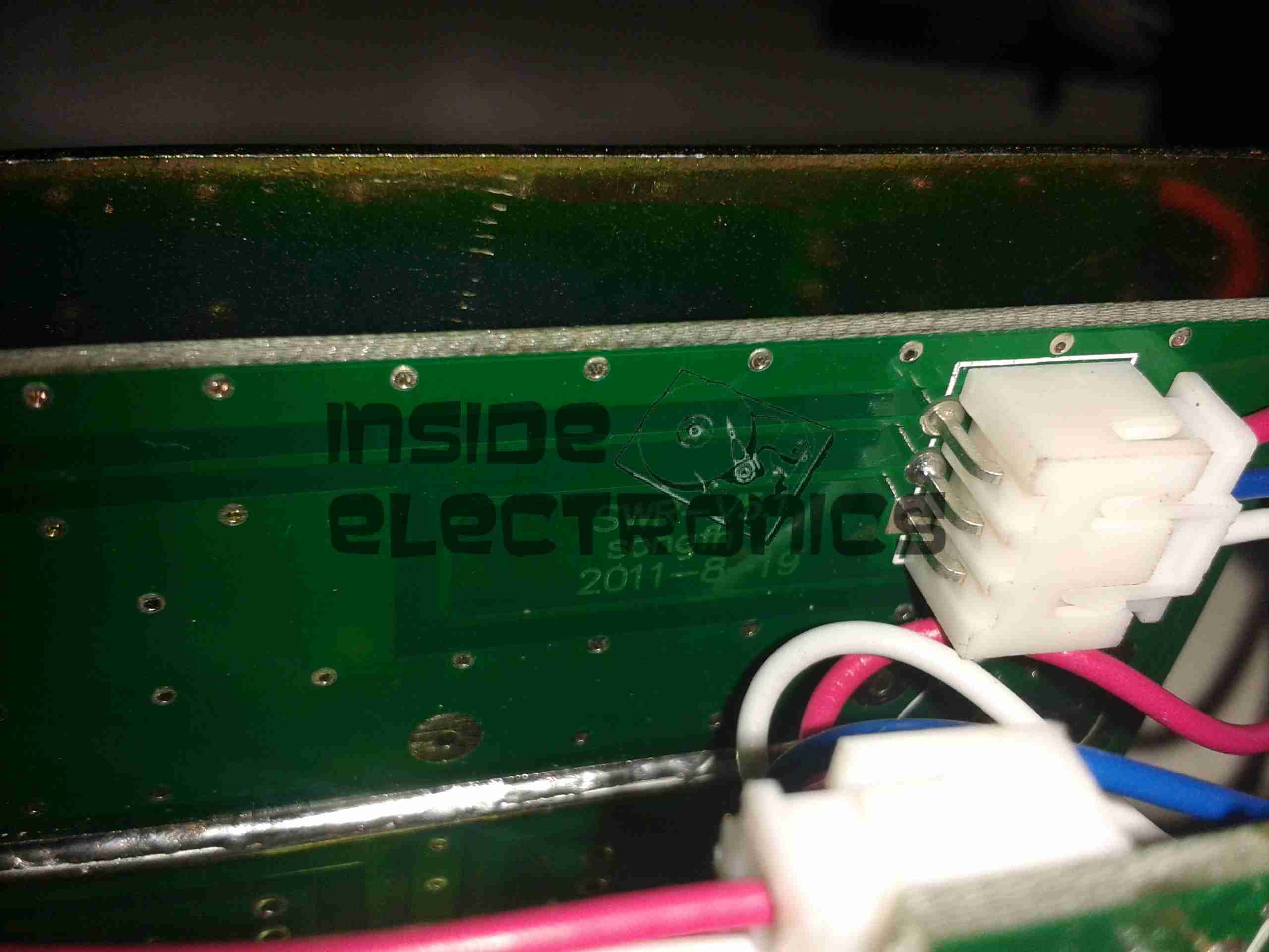
PCB Marking
The PCB is dated 19-8-2011, so it’s a fairly old design.
Adjustments
Here is visible the back of the user calibration adjuster, with the factory calibration trimmer.
Meter Movement
Back of the meter movement. This is a standard moving coil type. Nothing special.
This meter will soon be modified to accept connection of an external Arduino-based SWR & power meter, which I can calibrate individually for each band.
Stay tuned for that upcoming project.
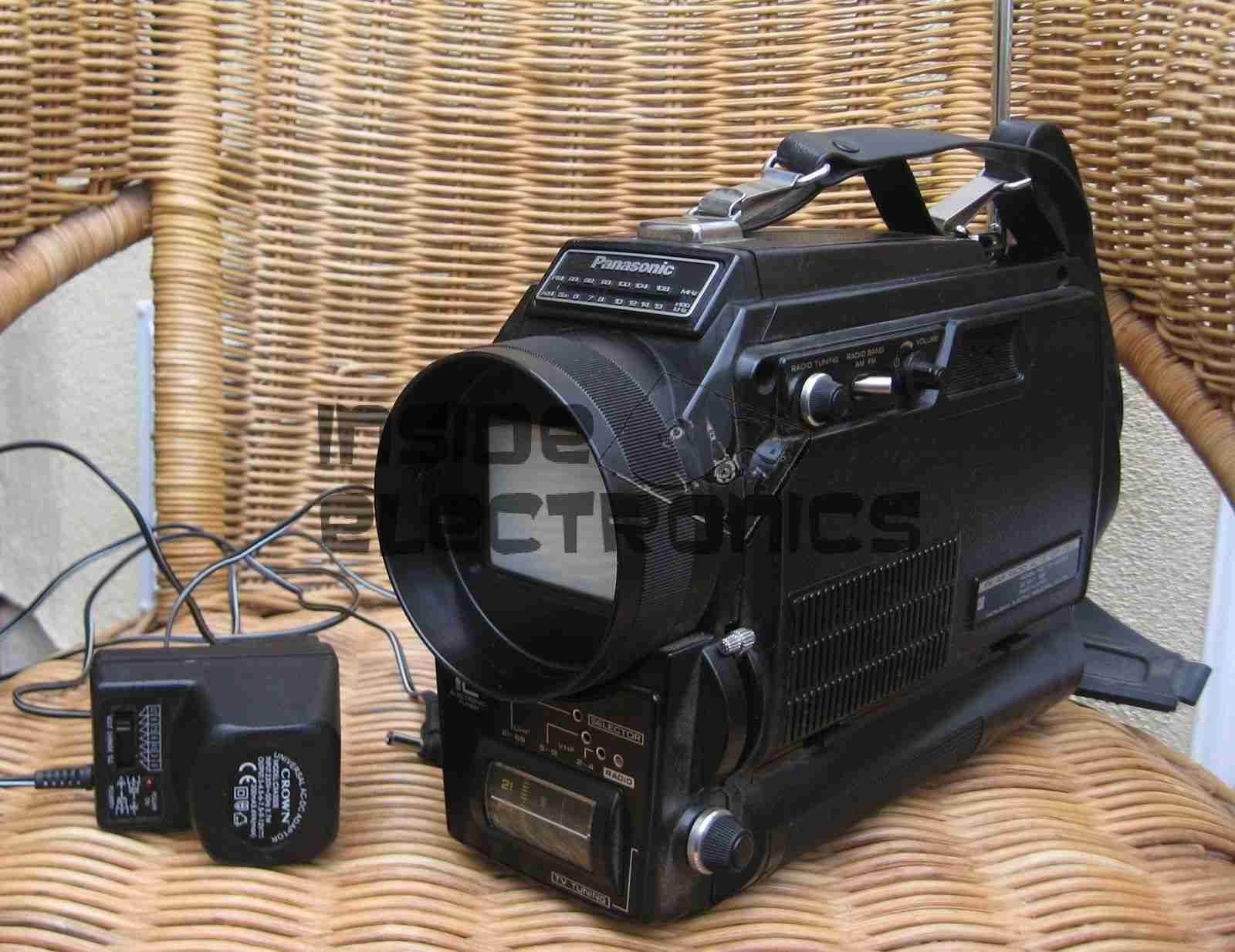
I recently managed to score a 3″ B&W portable TV on eBay, a Panasonic TR-3000G. As these old units are now useless, thanks to the switch off of analogue TV signalling, I figured I could find a composite signal internally & drive the CRT with an external source.
Panasonic TR-3000G
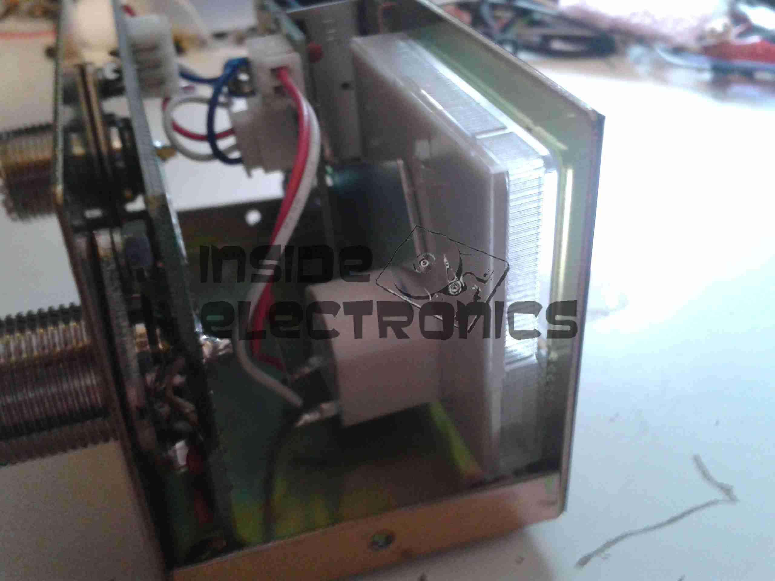
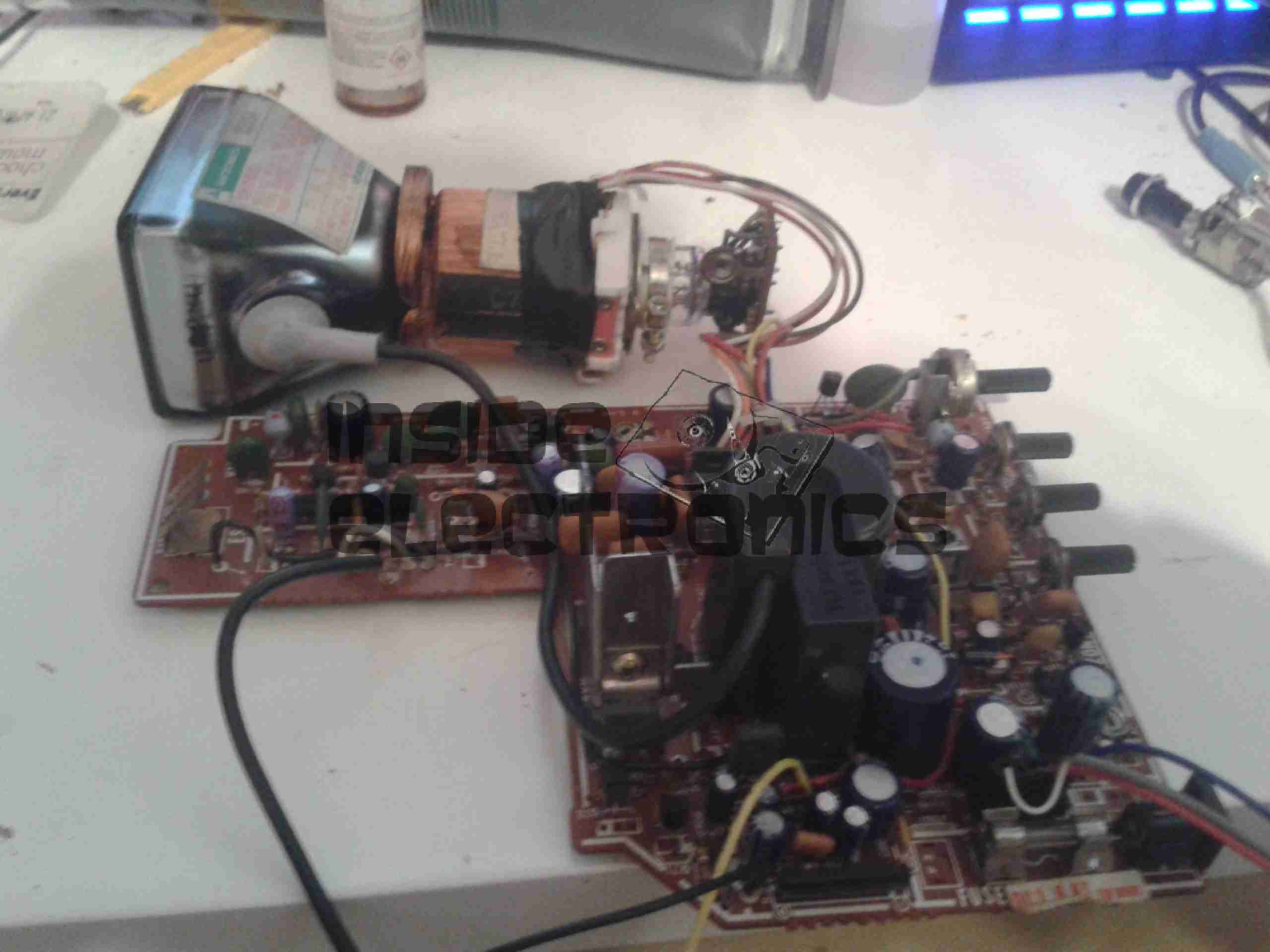
Here’s the TV in it’s native state. Running from 9v DC, or 6 D size cells. I’m guessing from somewhere around the 1970’s. Here is the CRT & associated drive circuitry, removed from the casing:
CRT Module
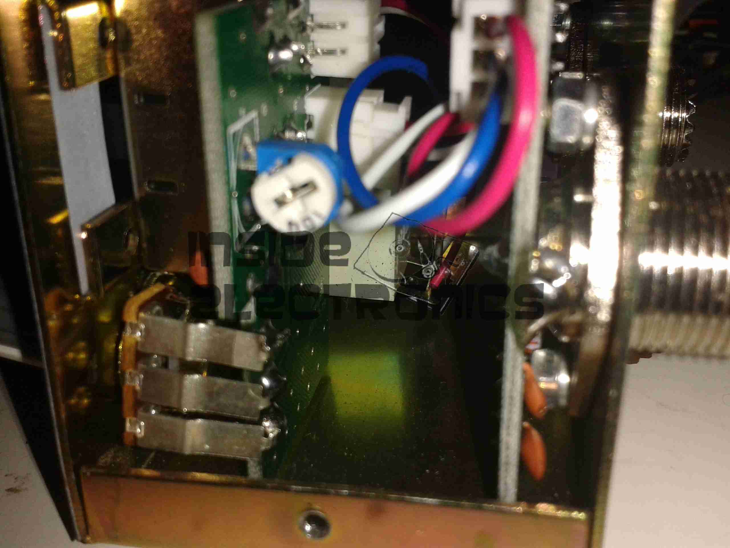
After dissecting the loom wiring between the CRT board & the RF/tuner board, I figured out I had to short out Pins 1,2 & 5 on the H header to get the CRT to operate straight from the power switch. This board also generates the required voltages & signals to drive the RF tuner section. I have removed the loom from this, as the PCB operates fine without. It doesn’t seem to be fussy about power input either: it’s specified at 9v, but seems to operate fine between 7.5v & 14.5v DC without issue.
Video Connections
Tracing the wiring from the tuner PCB revealed a length of coax snaking off to the section marked Video/Sync. I successfully found the composite input!
Running OSMC
A quick bit of wiring to a Raspberry Pi, & we have stable video! For such an old unit, the picture quality is brilliant, very sharp focus.
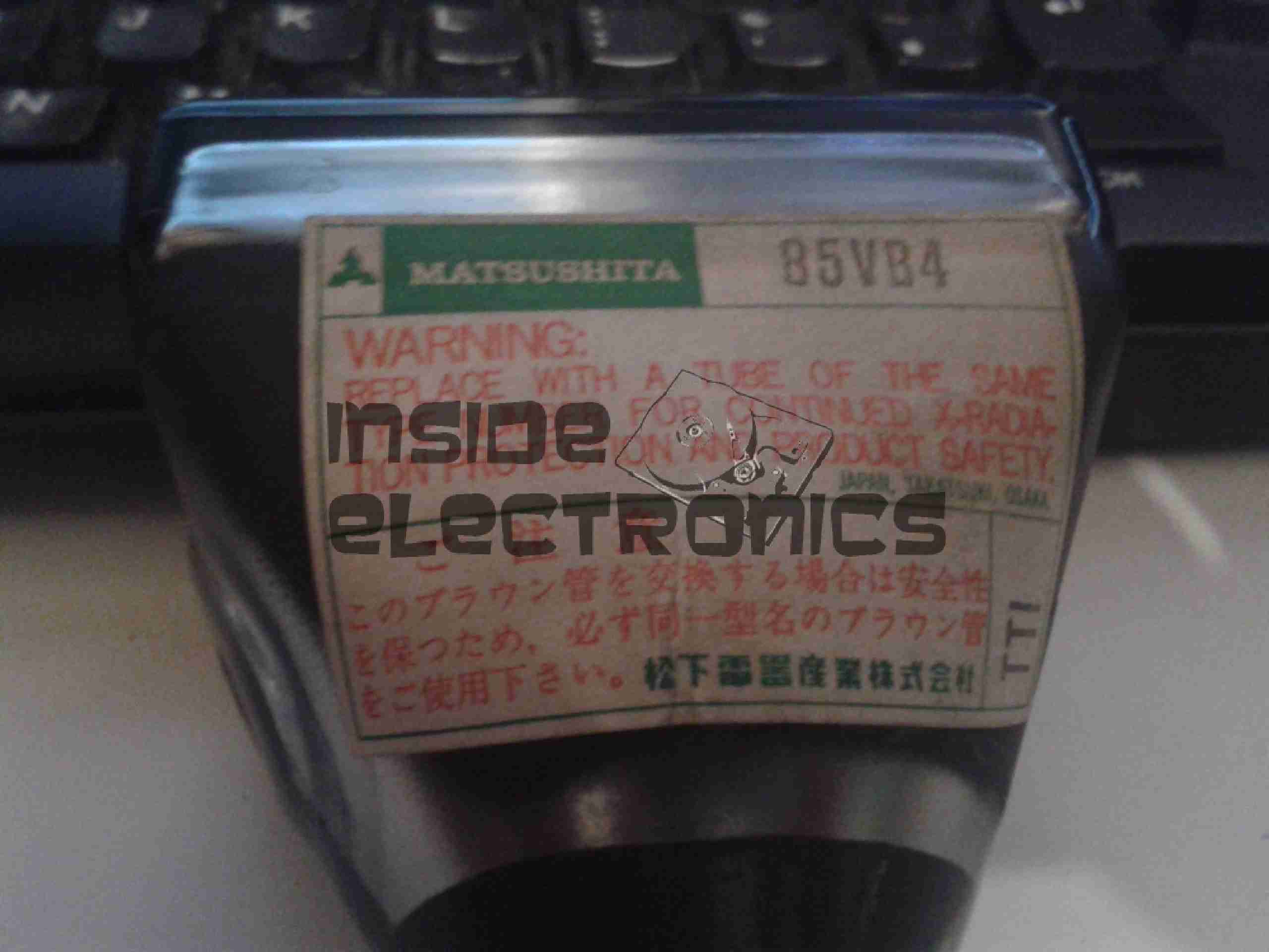
Matsushita 85VB4 CRT
Closeup of the CRT itself. I haven’t been able to find much data on this unit, but I’m guessing it’s similar to many commercial viewfinder CRTs.
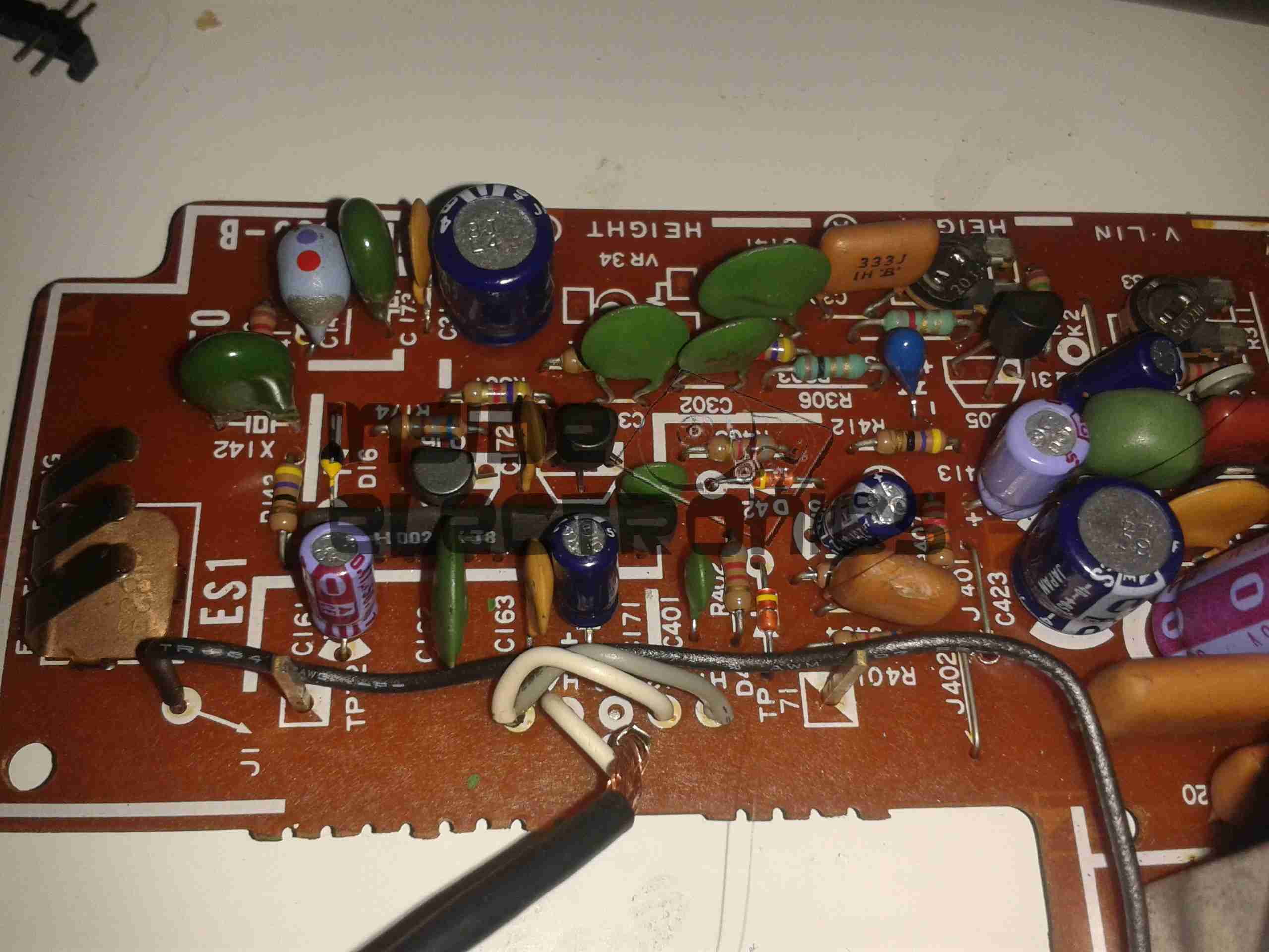
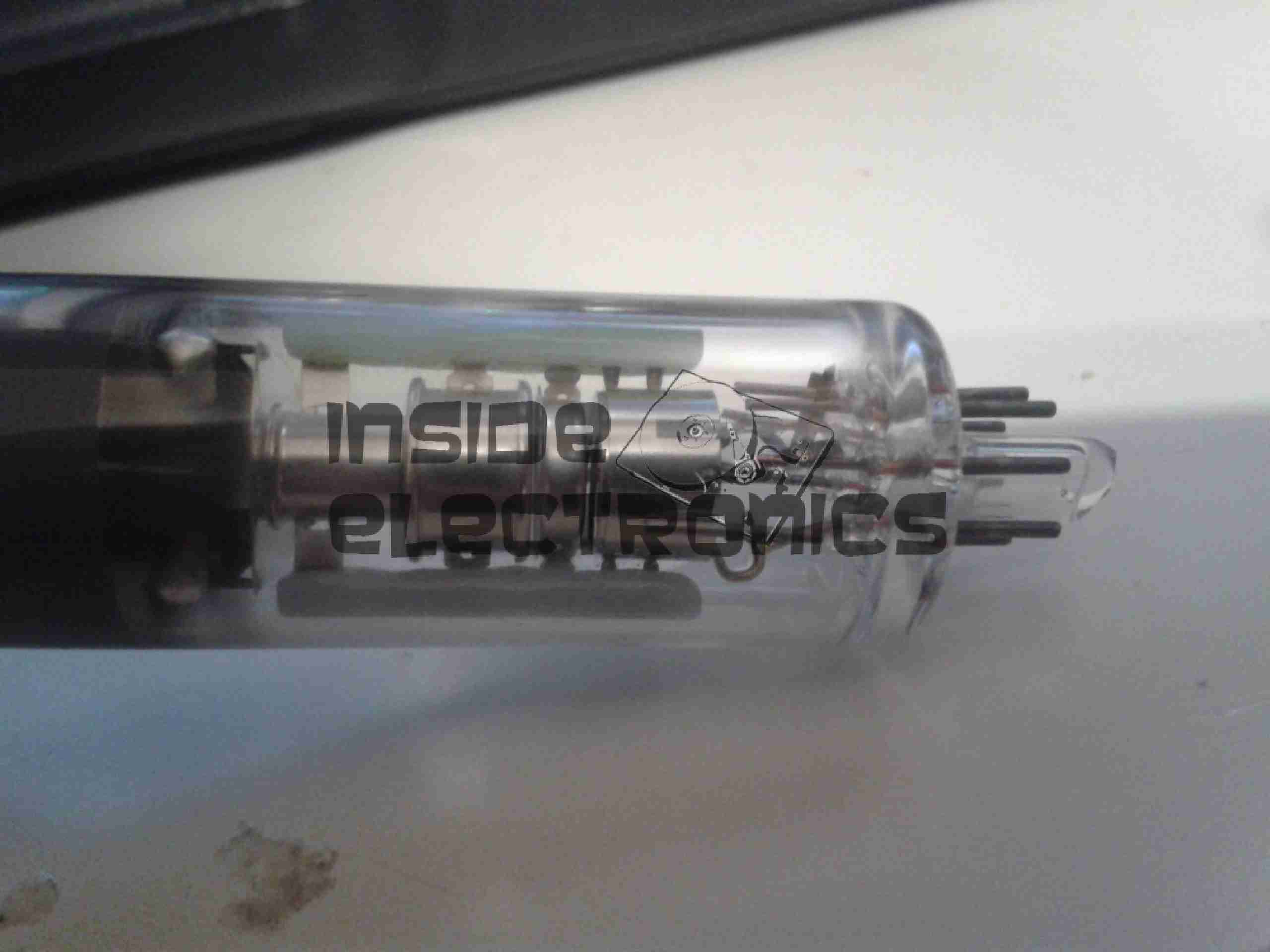
Electron Gun Closeup
Amazingly, there isn’t a single IC in the video circuitry, it’s all discrete components. This probably accounts for the large overall size of the control PCB. Viewfinder CRTs from a few years later on are usually driven with a single IC & a few passives that provide all the same functions.
To provide more run time with the conversion to petrol & spark ignition, I have also upgraded the on-board electronics supply to compensate for the extra ~650mA draw of the ignition module.
This modification is centred around a 3S Lithium-Polymer battery pack, providing a nominal 11.1v to a voltage regulator, which steps down this higher voltage to the ~6v required by the receiver & servo electronics.
Power RegulatorPower Regulator
The regulator, shown above, is a Texas Instruments PTN78060WAZ wide-input voltage adjustable regulator. This module has an exceptionally high efficiency of ~96% at it’s full output current of 3A. The output voltage is set by a precision resistor, soldered to the back of the module, in this case 6.5v. Standard RC connectors are used on the regulator to allow connection between the power switch & the radio receiver.
Receiver Box
Everything tucked away into place inside the receiver box. The 3S 1000mAh LiPo fits perfectly in the space where the original Ni-Mh hump pack was located.
The completely stable output voltage of the regulator over the discharge curve of the new battery gives a much more stable supply to the radio & ignition, so I should experience fewer dropouts. Plus the fact that the engine now relies on power from the receiver pack to run, it’s a built in fail safe – if the power dies to the receiver, the engine also cuts out.
Tip Jar
If you’ve found my content useful, please consider leaving a donation by clicking the Tip Jar below!
All collected funds go towards new content & the costs of keeping the server online.