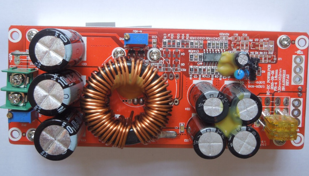
Ah the curse of the Chinese Electronics strikes again. These large DC-DC boost converters have become very common on the likes of AliExpress & eBay, and this time my order has arrived DOA… On applying power, the output LED lights up dimly, and no matter how I twiddle the adjustment pots, the output never rises above the input voltage.
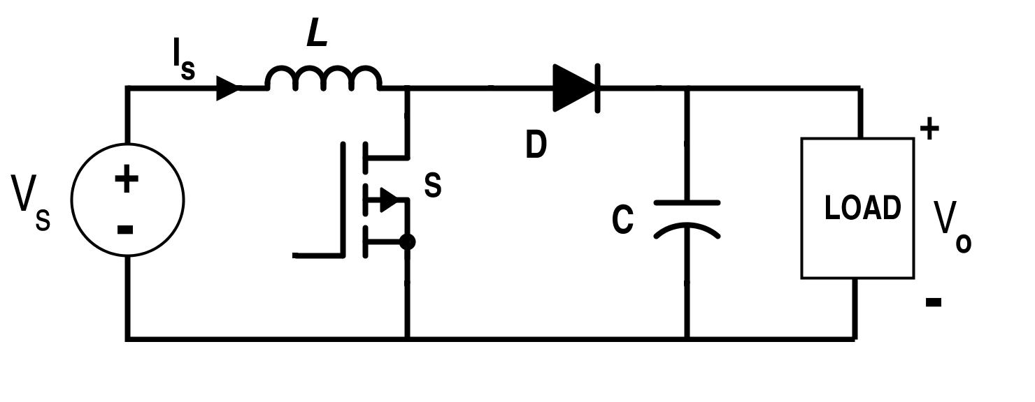
Boost Converter Topology
From the usual topology above, we can assume that the switching converter isn’t working, so the input voltage is just being directly fed through to the output. The switching IC on these converters is a TL494,
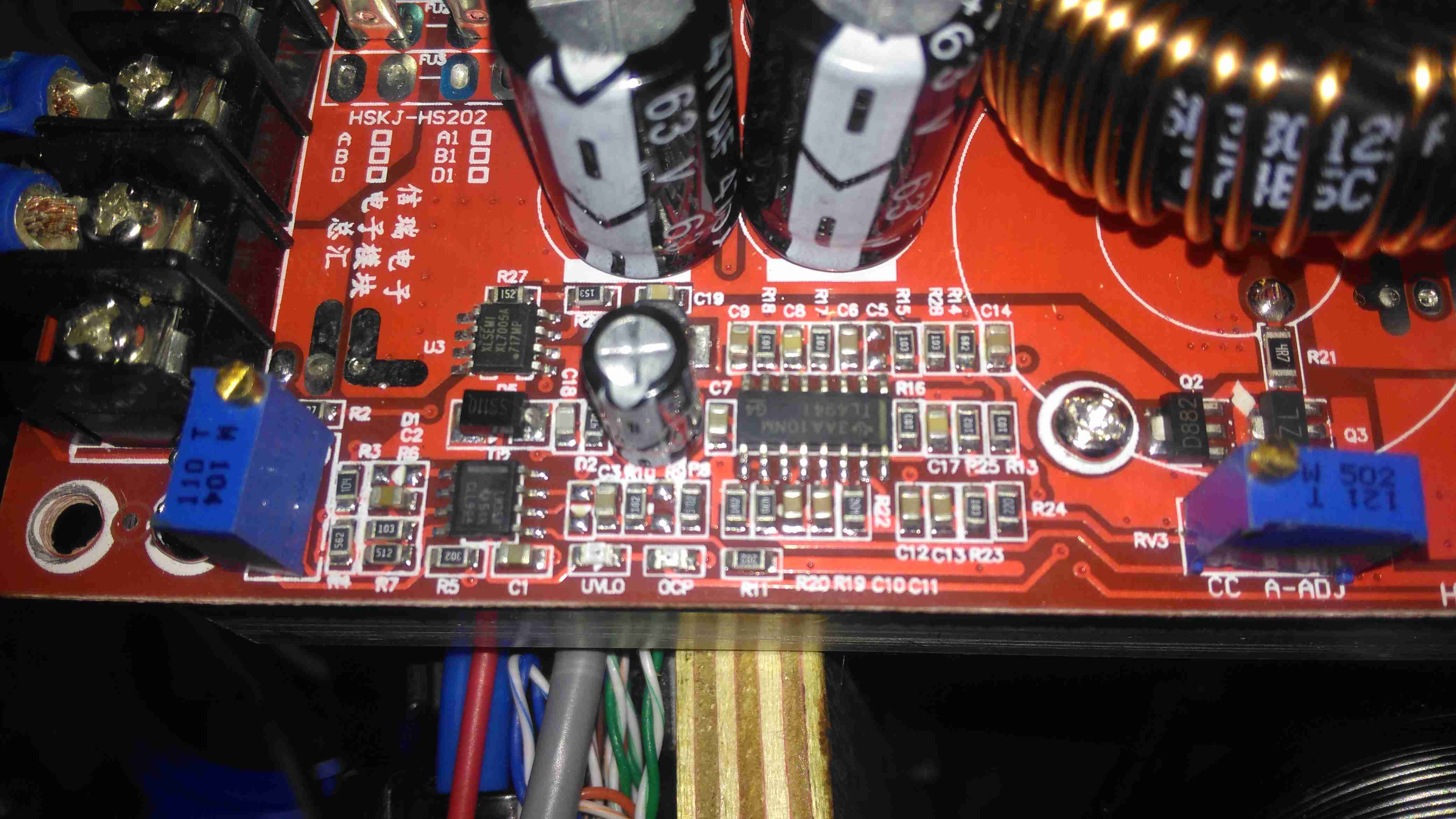
Control Circuitry
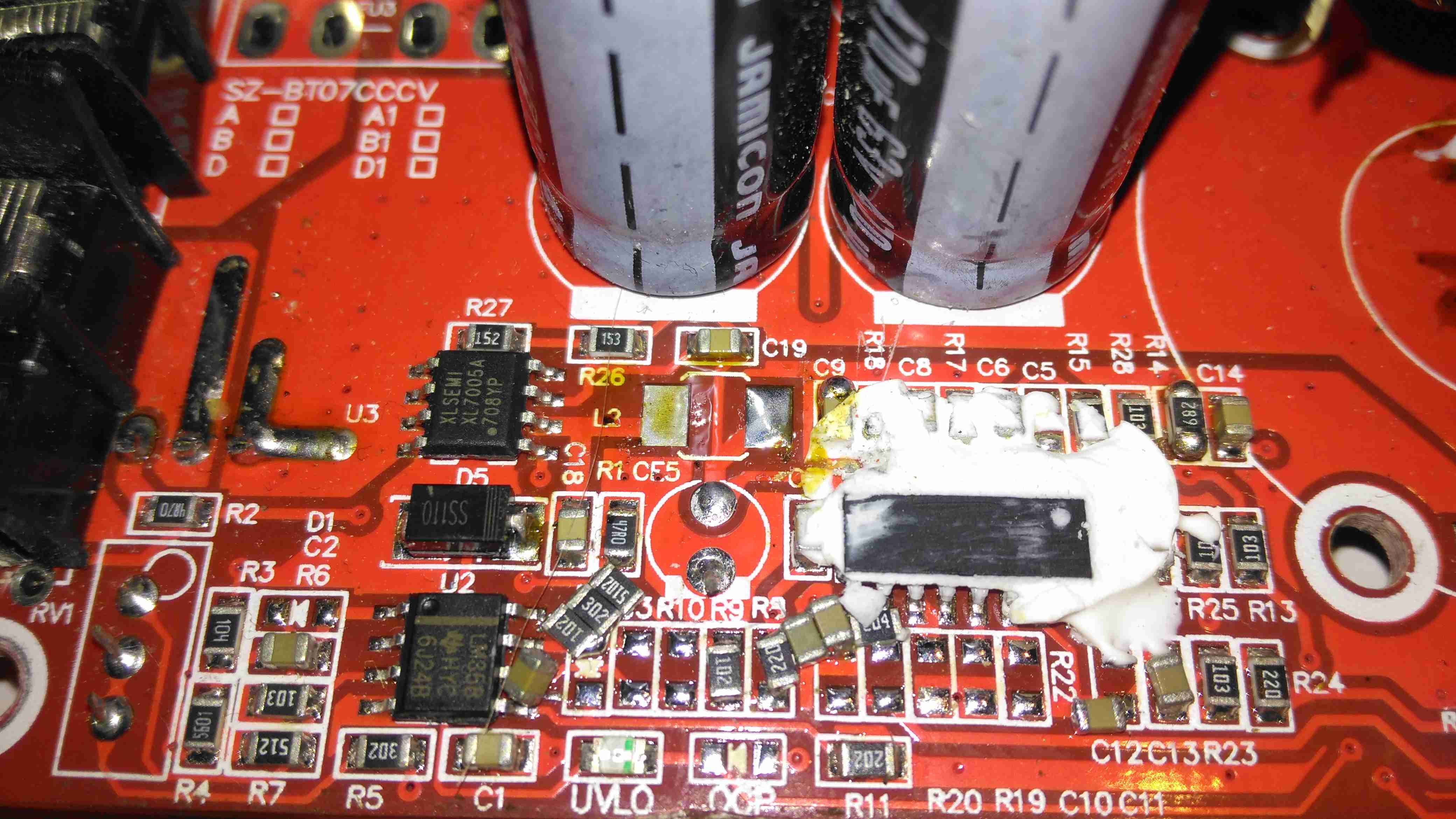
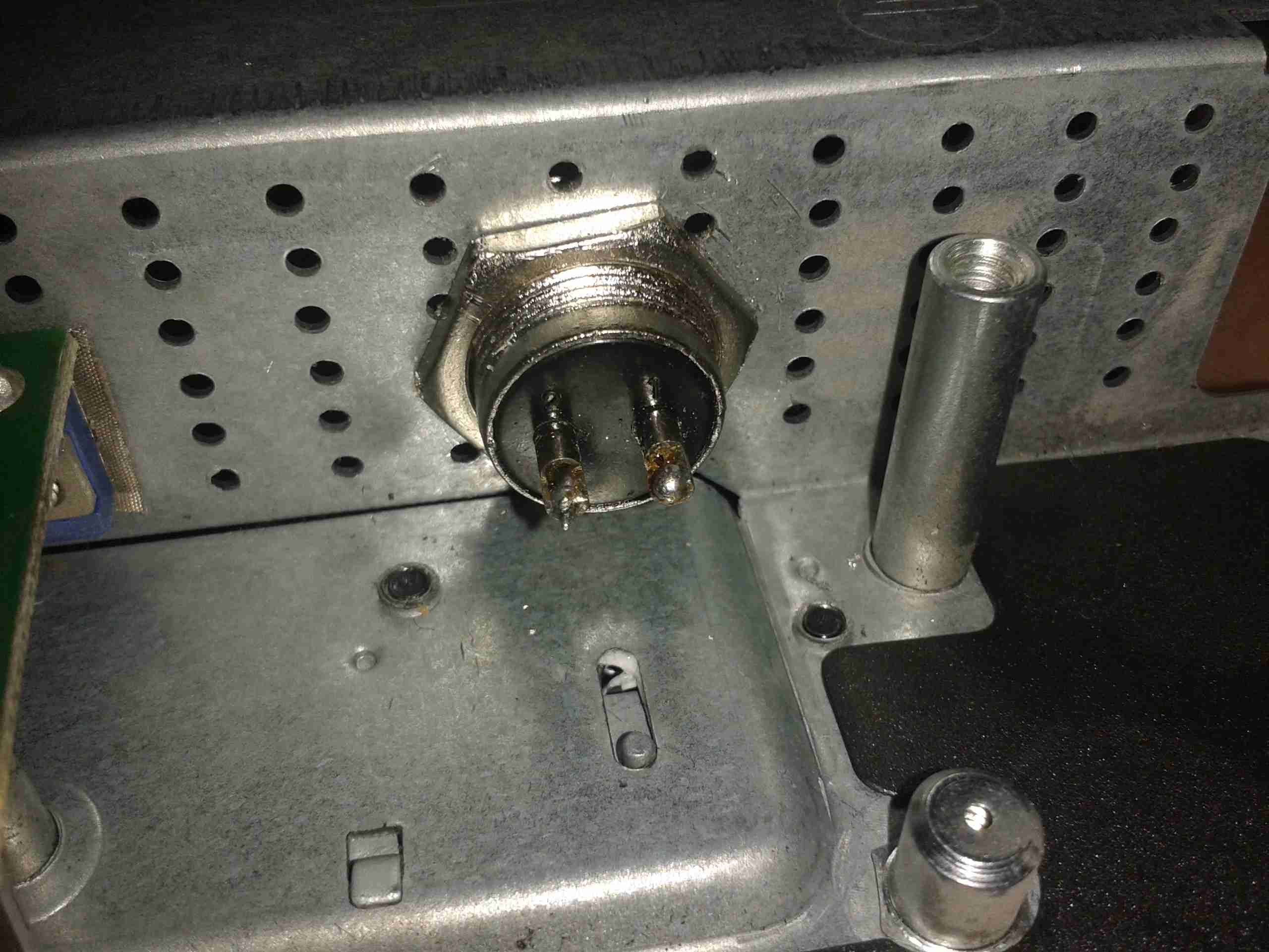
The switching IC on these converters is a TL494,with it’s surrounding support components, including a LM358 dual Op-Amp. Power for this lot is supplied from the input via a small DC-DC converter controlled by an XL Semi XL7001 Buck Converter IC. Some testing revealed that power was getting to the XL7001, but the output to the switching controller was at zero volts.
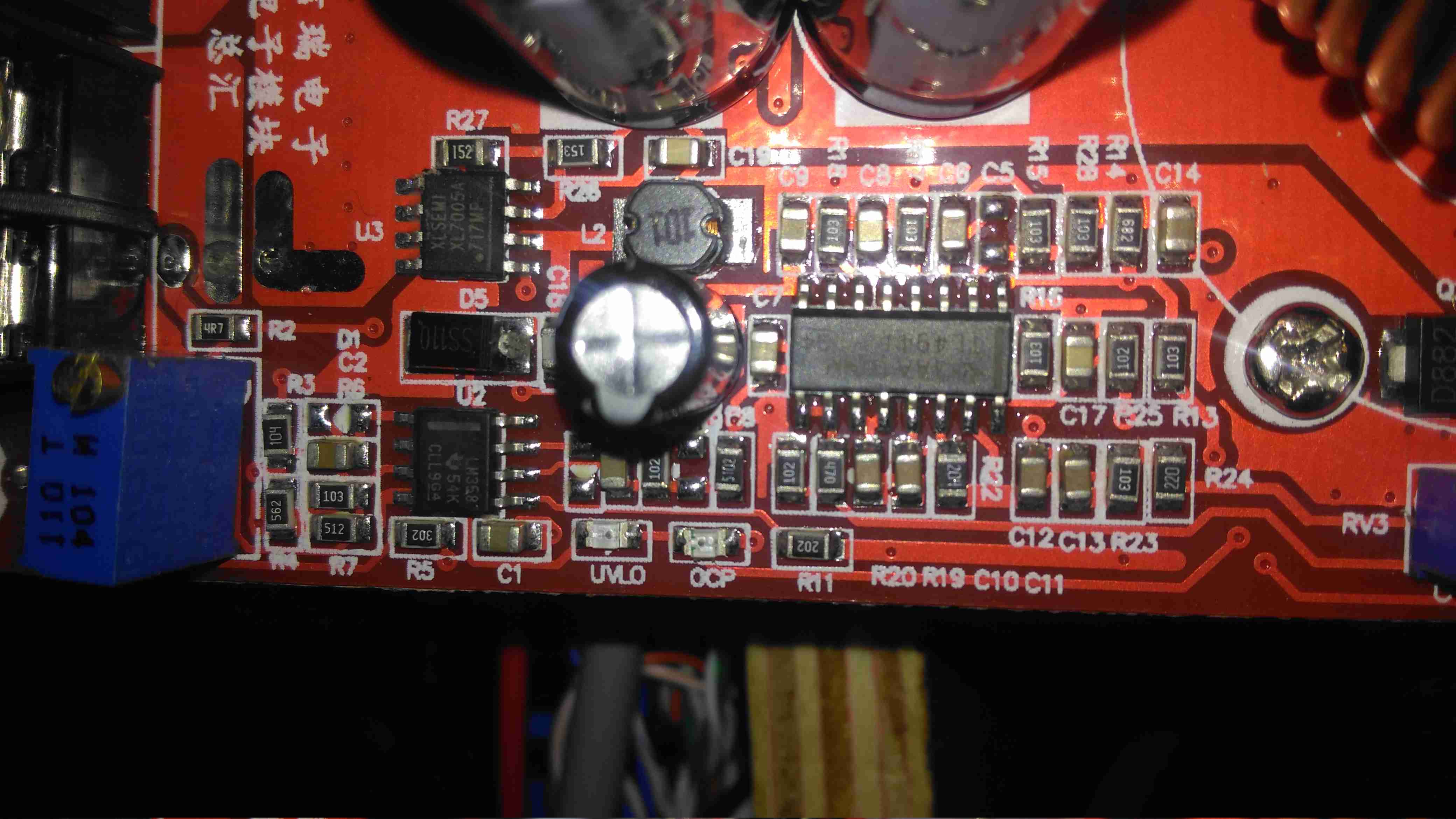
Inductor
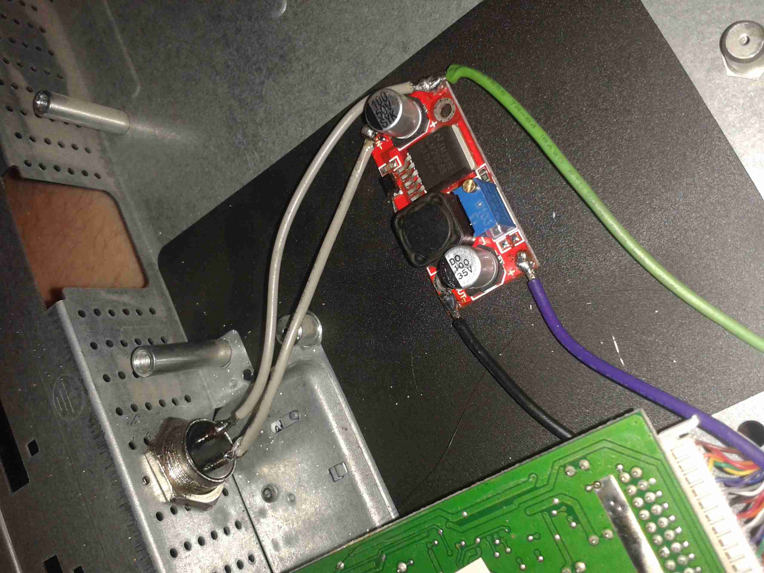
The 100µH inductor for this buck converter is hidden behind the output electrolytic, and a quick prod with a multimeter revealed this inductor to be open circuit. That would certainly explain the no-output situation. Luckily I had an old converter that was burned out. (Don’t try to pull anything near their manufacturer “rating” from these units – it’s utter lies, more about this below).
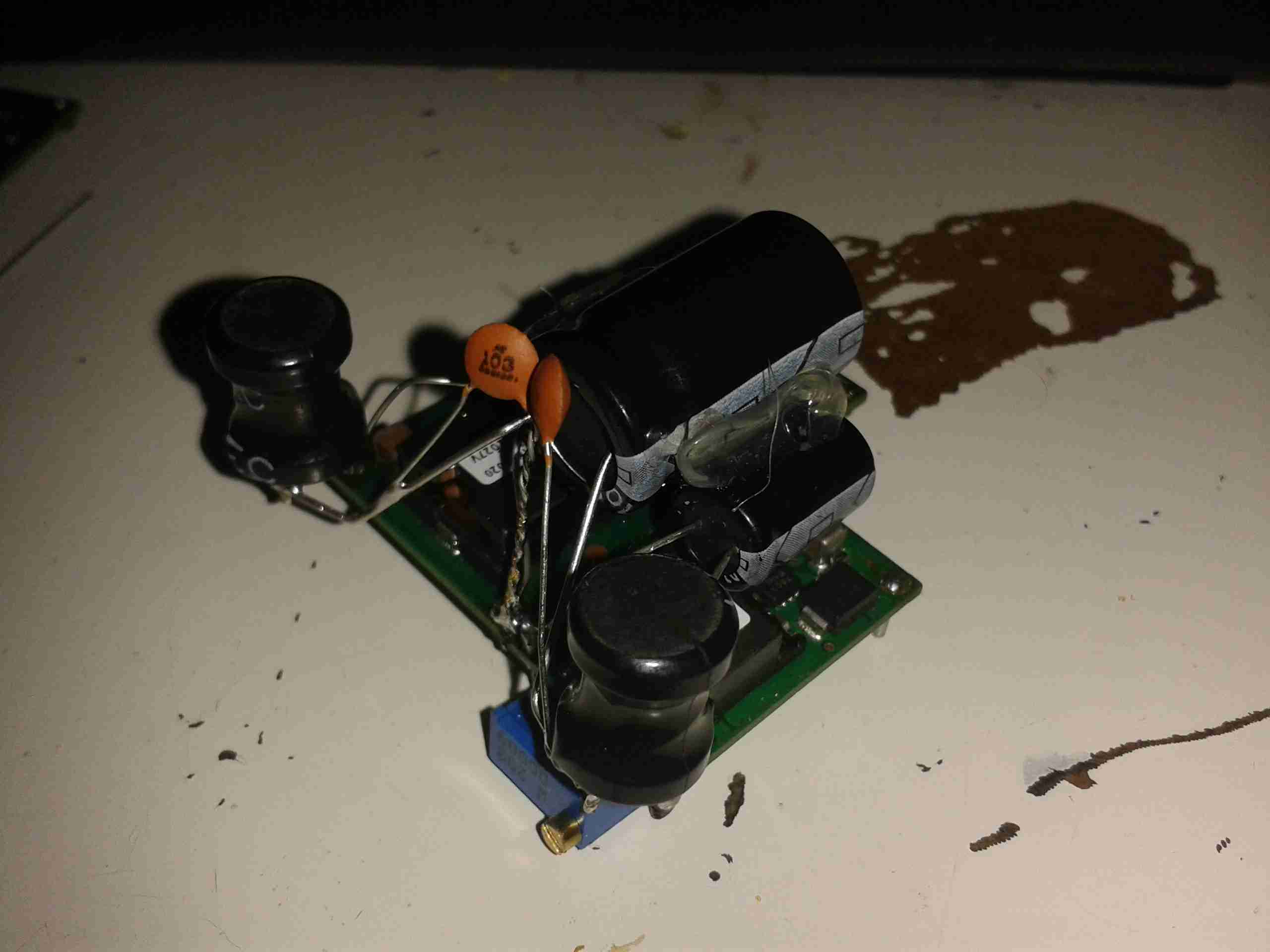
Donor Converter
The good inductor from this donor unit has been desoldered here, it’s supposed to be L2. This one had a heatsink siliconed to the top of the TL494 PWM IC, presumably for cooling, so this was peeled off to give some access.
After this inductor was grafted into place on the dead converter, everything sprang to life as normal. I fail to see how this issue wouldn’t have been caught during manufacture, but they’re probably not even testing them before shipping to the distributor.
The sensational ratings are also utter crap – they quote 1.2kW max power, which at 12v input would be 100A. Their max input rating is given as 20A, so 240W max input power. Pulling this level of power from such a cheaply designed converter isn’t going to be reliably possible, the input terminals aren’t even rated to anywhere near 20A, so these would be the first to melt, swiftly followed by everything else. Some of these units come with a fan fitted from the factory, but these are as cheaply made as possible, with bearings made of cheese. As a result they seize solid within a couple of days of use.
Proper converters from companies like TDK-Lambda or muRata rated for these power levels are huge, with BOLTS for terminals, but they’re considerably more expensive. These Chinese units are handy though, as long as they are run at a power level that’s realistic.
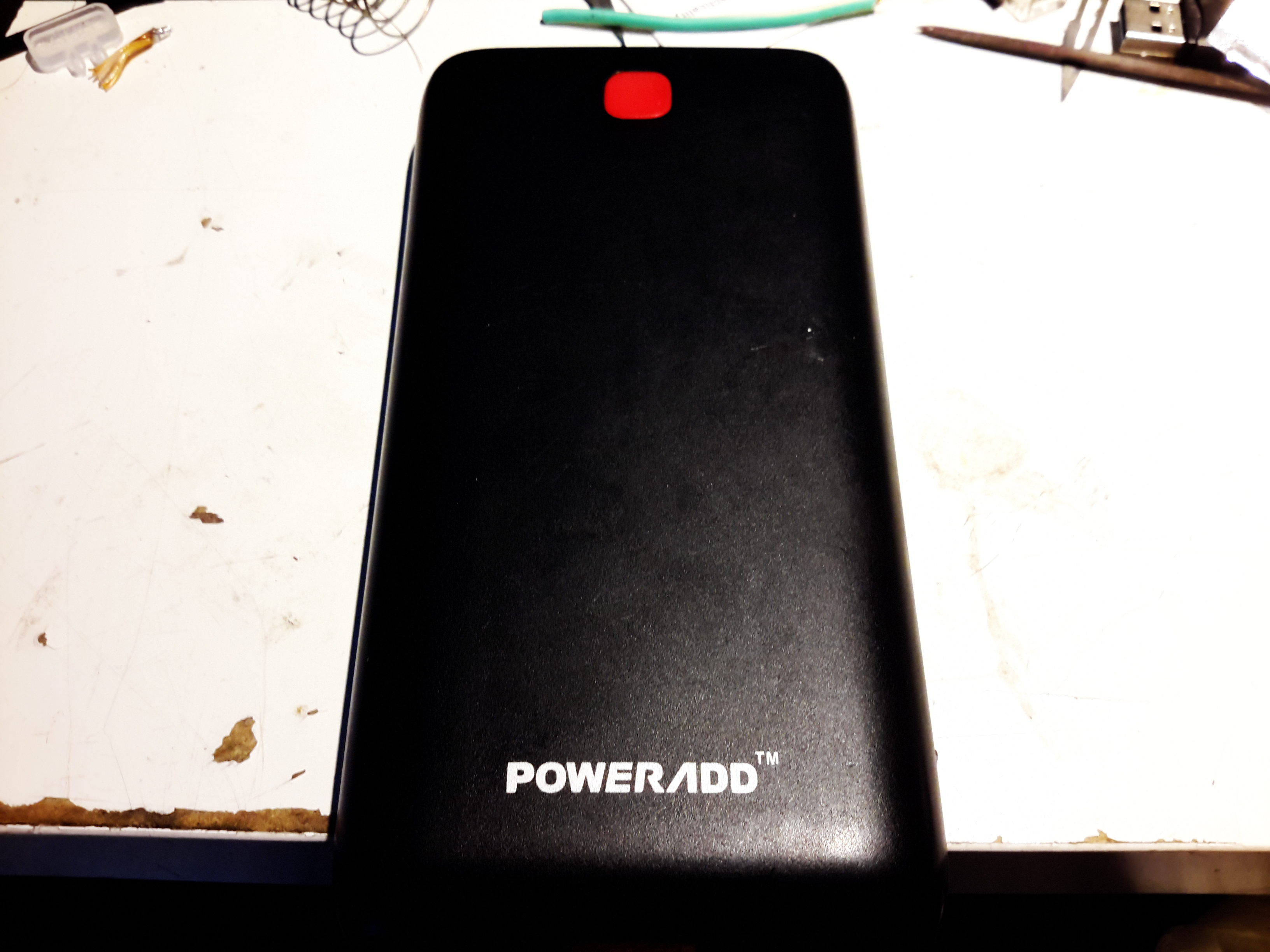
Here’s the biggest portable USB powerbank I’ve seen yet – the PowerAdd Pilot X7, this comes with a 20Ah (20,000mAh) capacity. This pack is pretty heavy, but this isn’t surprising considering the capacity.
USB Ports & LED
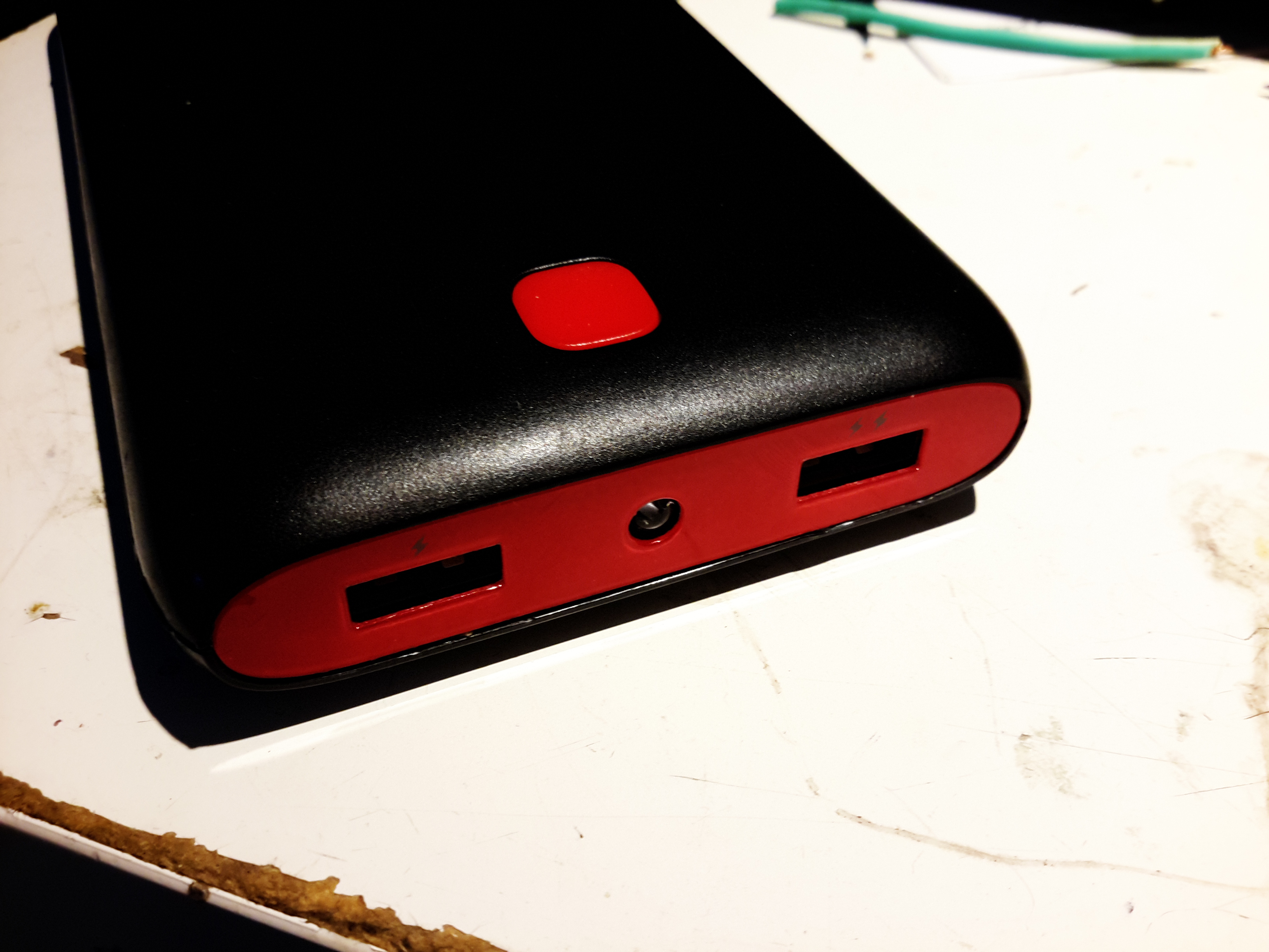
The front of the pack houses the usual USB ports, in this case rated at 3.4A total between the ports. There’s a white LED in the centre as a small torch, activated by double-clicking the button. A single click of the button lights up the 4 blue LEDs under the housing that indicate remaining battery capacity. Factory charging is via a standard µUSB connector in the side, at a maximum of 2A.
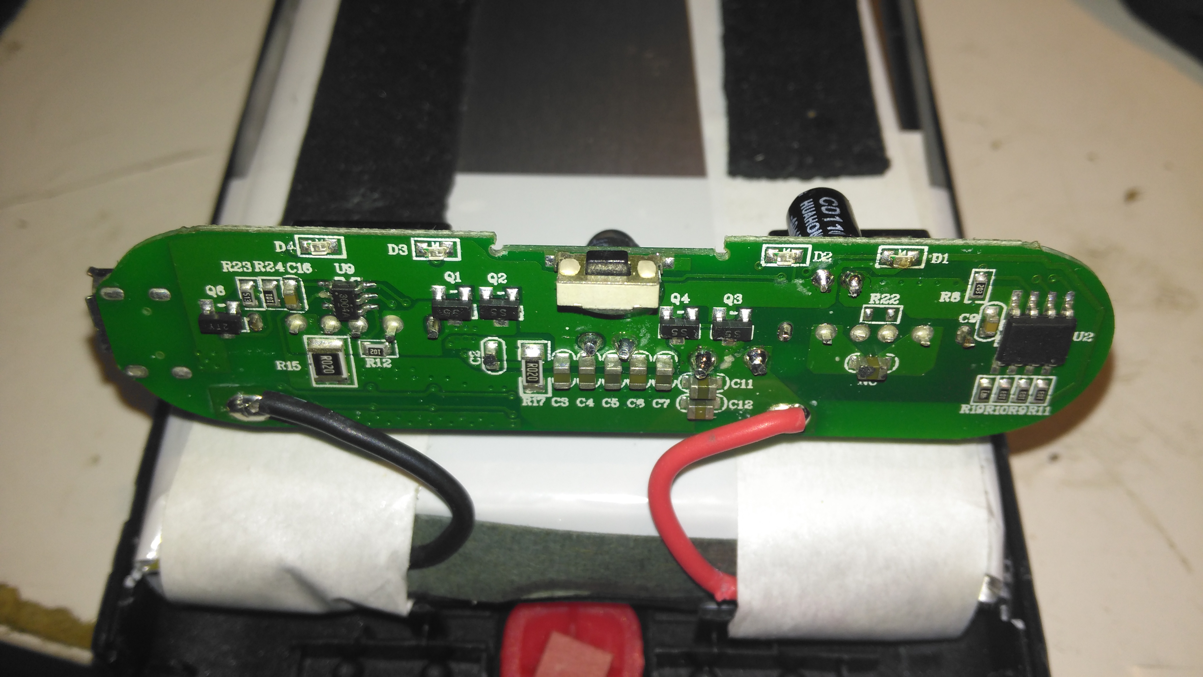
PCB Front
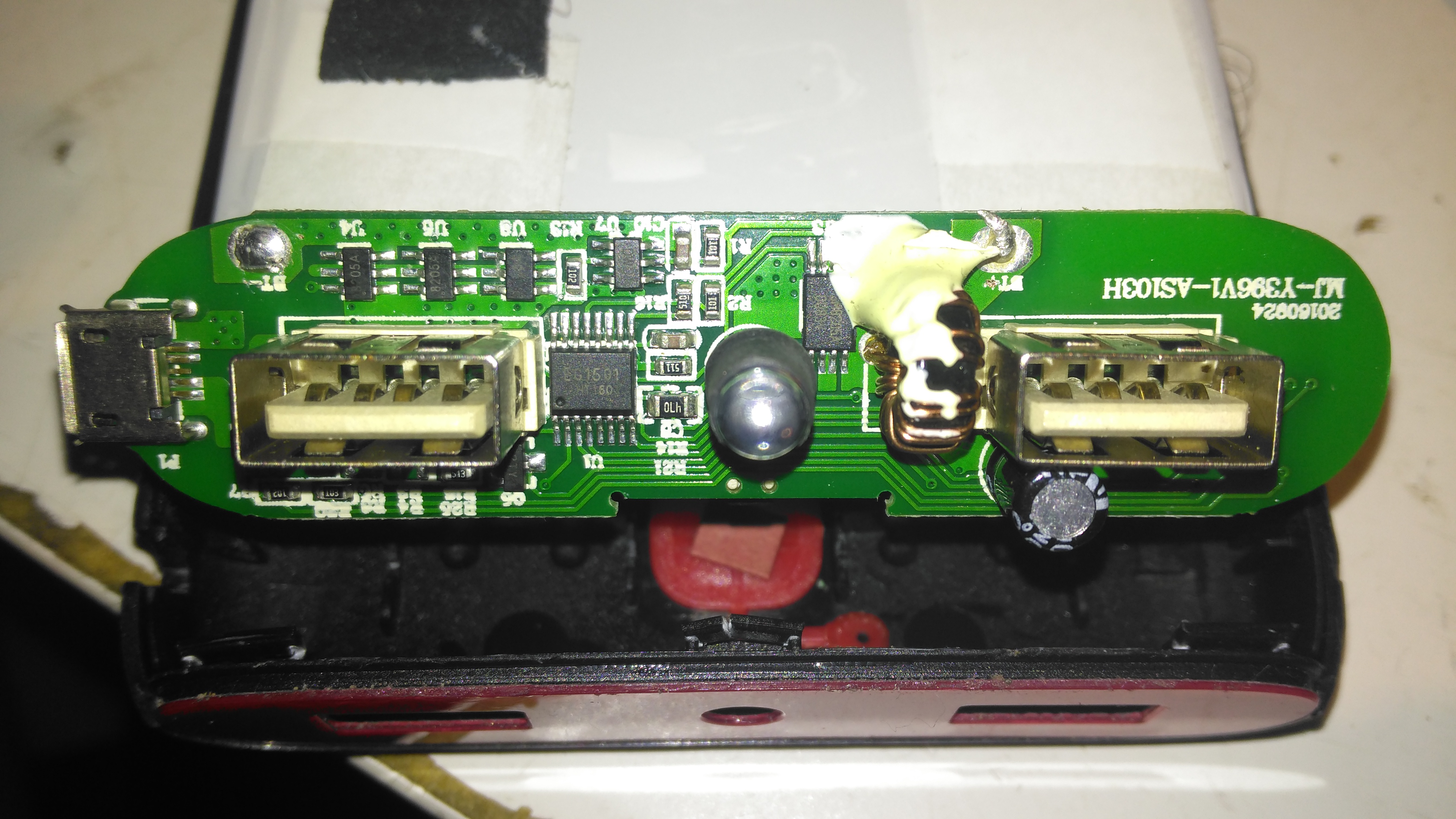
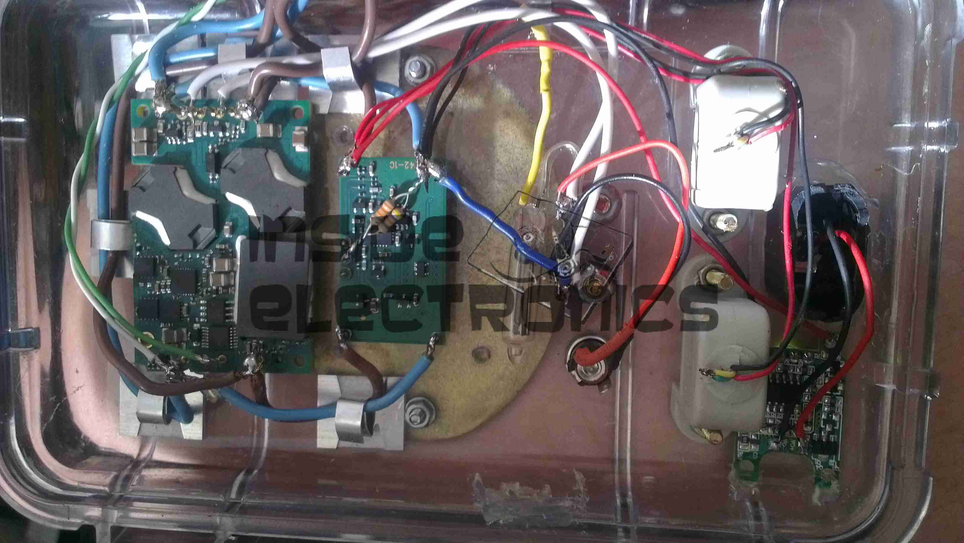
The front of the PCB holds the USB ports, along with most of the main control circuitry. At top left is a string of FS8025A dual-MOSFETs all in parallel for a current carrying capacity of 15A total, to the right of these is the ubiquitous DW01 Lithium-Ion protection IC. These 4 components make up the battery protection – stopping both an overcharge & overdischarge. The larger IC below is an EG1501 multi-purpose power controller.
This chip is doing all of the heavy lifting in this power pack, dealing with all the DC-DC conversion for the USB ports, charge control of the battery pack, controlling the battery level indicator LEDs & controlling the torch LED in the centre.
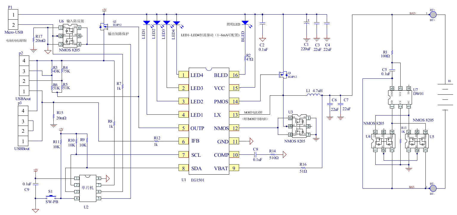
EG1501 Example
The datasheet is in Chinese, but it does have an example application circuit, which is very similar to the circuitry used in this powerbank. A toroidal inductor is nestled next to the right-hand USB port for the DC-DC converter, and the remaining IC next to it is a CW3004 Dual-Channel USB Charging Controller, which automatically sets the data pins on the USB ports to the correct levels to ensure high-current charging of the devices plugged in. This IC replaces the resistors R3-R6 in the schematic above.
The DC-DC converter section of the power chain is designed with high efficiency in mind, not using any diodes, but synchronous rectification instead.
PCB Back
The back of the PCB just has a few discrete transistors, the user interface button, and a small SO8 IC with no markings at all. I’m going to assume this is a generic microcontroller, (U2 in the schematic) & is just there to interface the user button to the power controller via I²C.
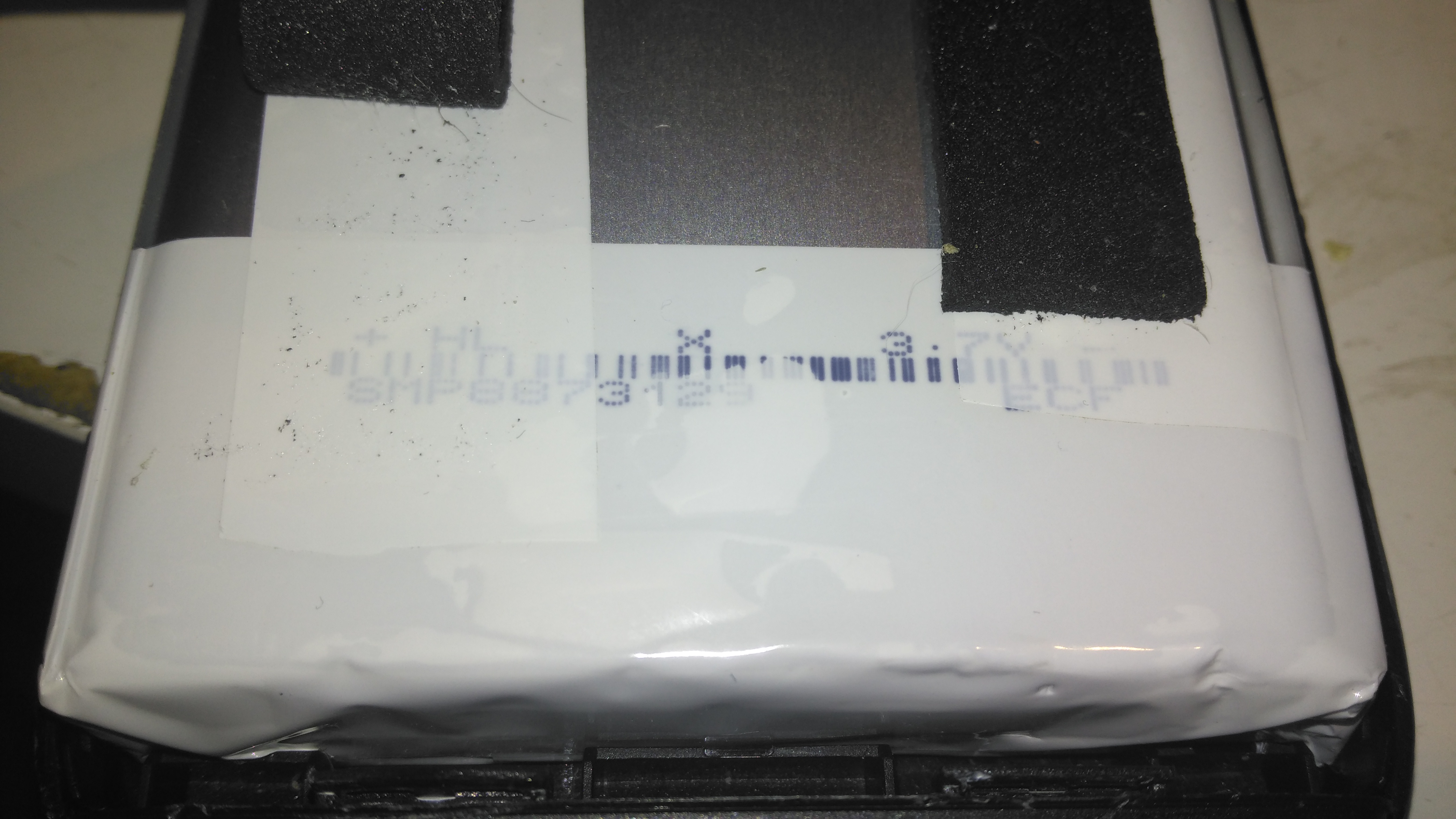
Cells
Not many markings on the cells indicating their capacity, but a full discharge test at 4A gave me a resulting capacity of 21Ah – slightly above the nameplate rating. There are two cells in here in parallel, ~10Ah capacity each.
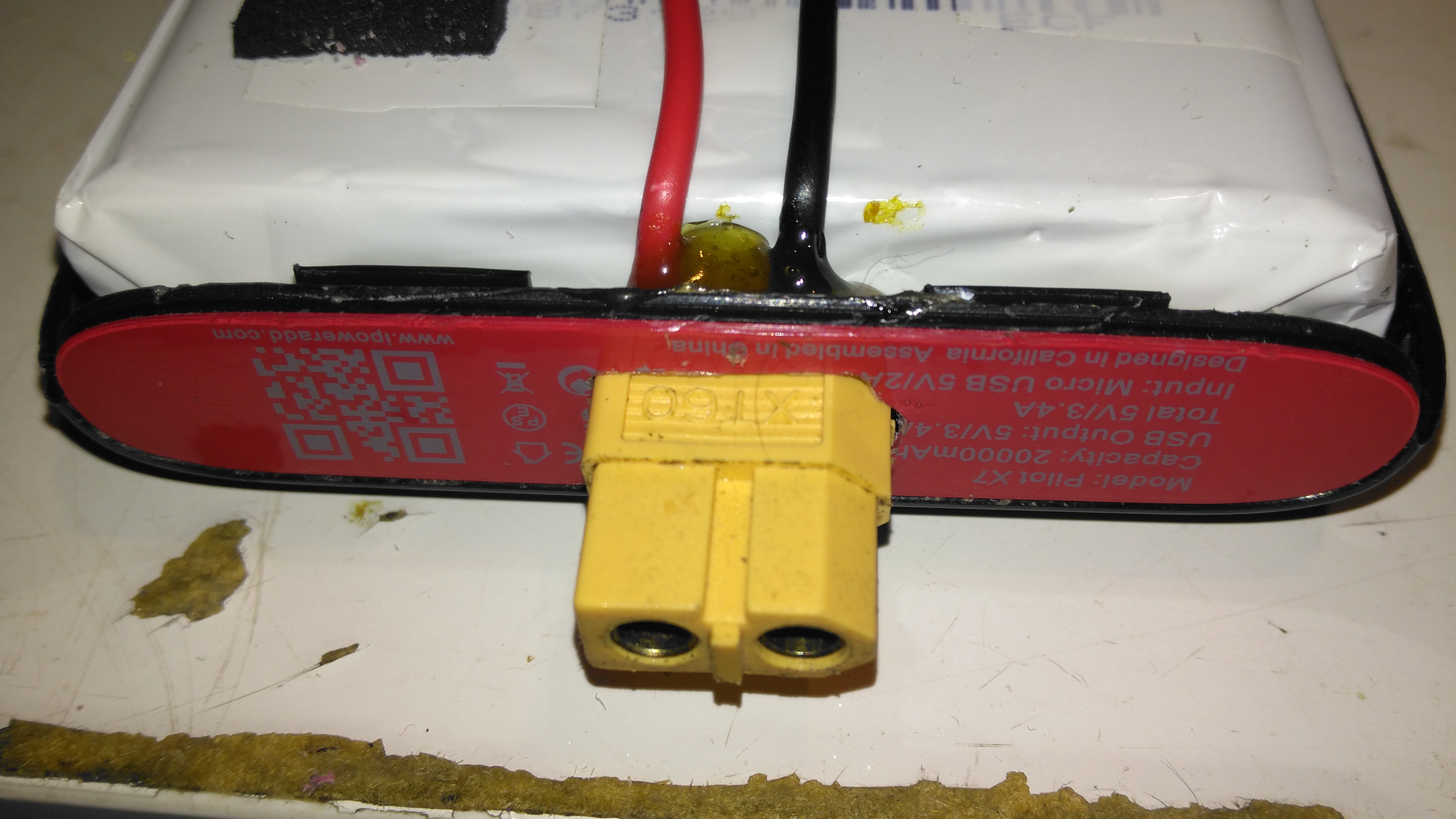
XT60 Battery Connector
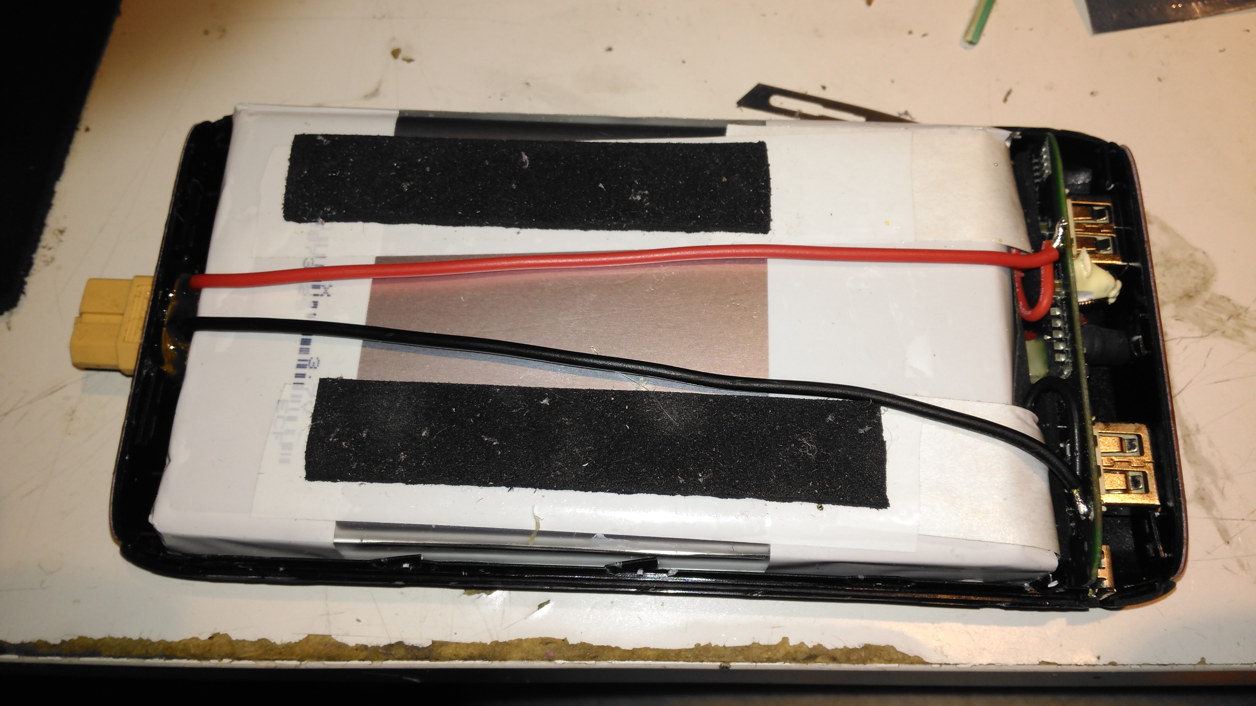
The only issue with powerbanks this large is the amount of time they require to recharge themselves – at this unit’s maximum of 2A through the µUSB port, it’s about 22 hours! Here I’ve fitted an XT60 connector, to interface to my Turnigy Accucell 6 charger, increasing the charging current capacity to 6A, and reducing the full-charge time to 7 hours. This splits to 3A charge per cell, and after some testing the cells don’t seem to mind this higher charging current.
Battery Connector Wiring
The new charging connector is directly connected to the battery at the control PCB, there’s just enough room to get a pair of wires down the casing over the cells.
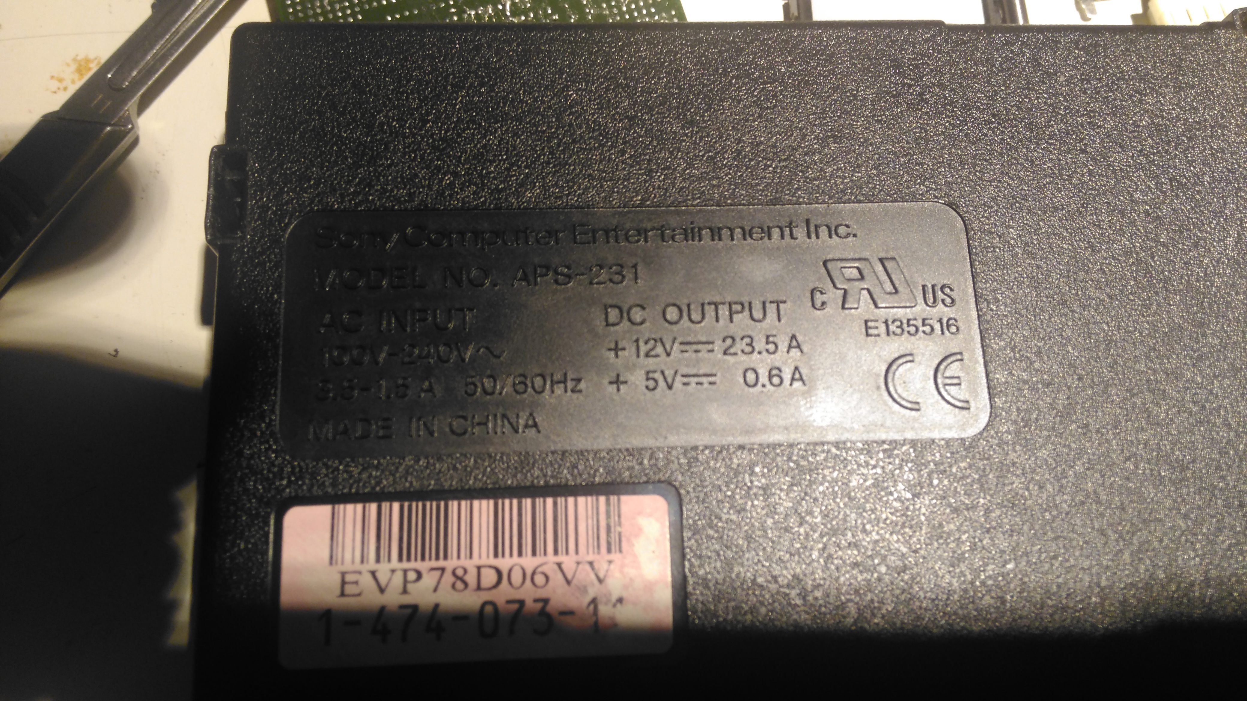
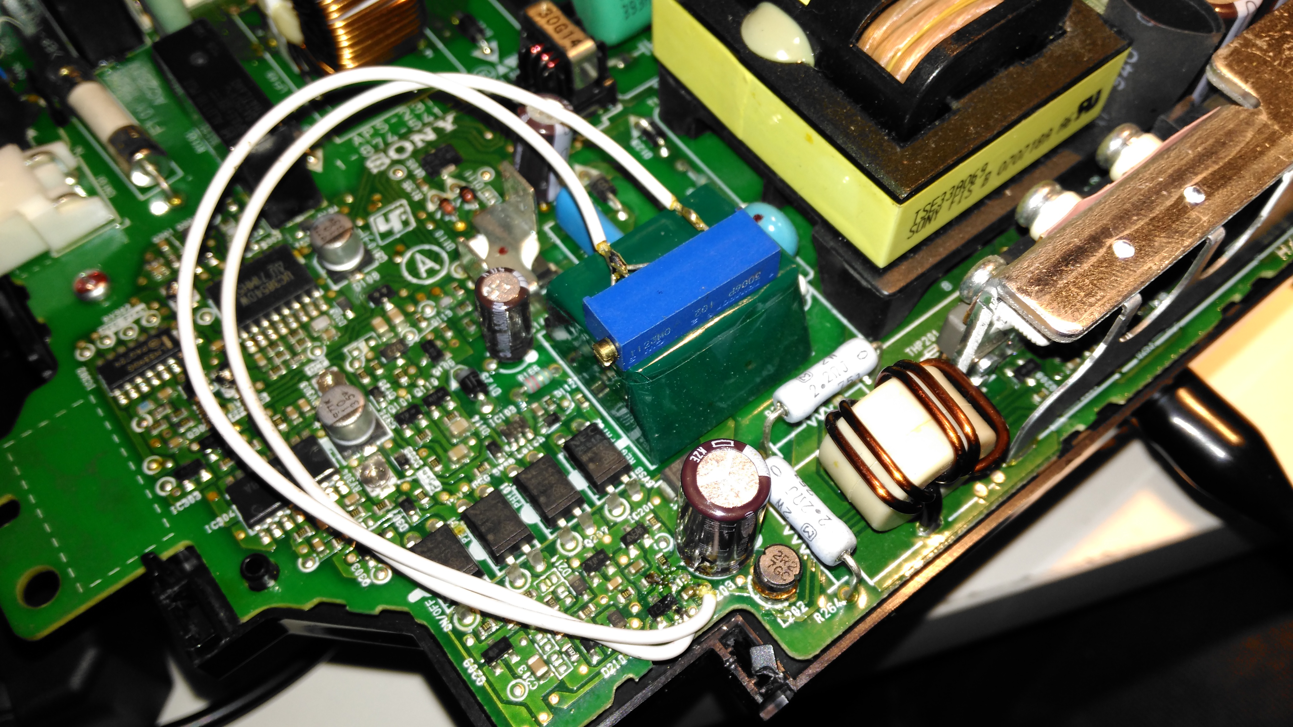
I was recently given a Sony PS3 with a dead disc drive, and since I’m not a console gamer I figured I’d see if there were any handy parts inside. Turns out these units contain a rather nice SMPS, the Sony APS-231 with a high power 12v rail, rated at 23.5A. A bit of searching around discovered a thread on the BadCaps Forums about voltage modding these supplies for a 13.8v output, suitable for my Ham radio gear.
These supplies are controlled by a Sony CXA8038A, for which there is very little information. Active PFC is included, along with synchronous rectification which increases the efficiency of the supply, and in turn, reduces the waste heat output from the rectifiers.
Regulation Section
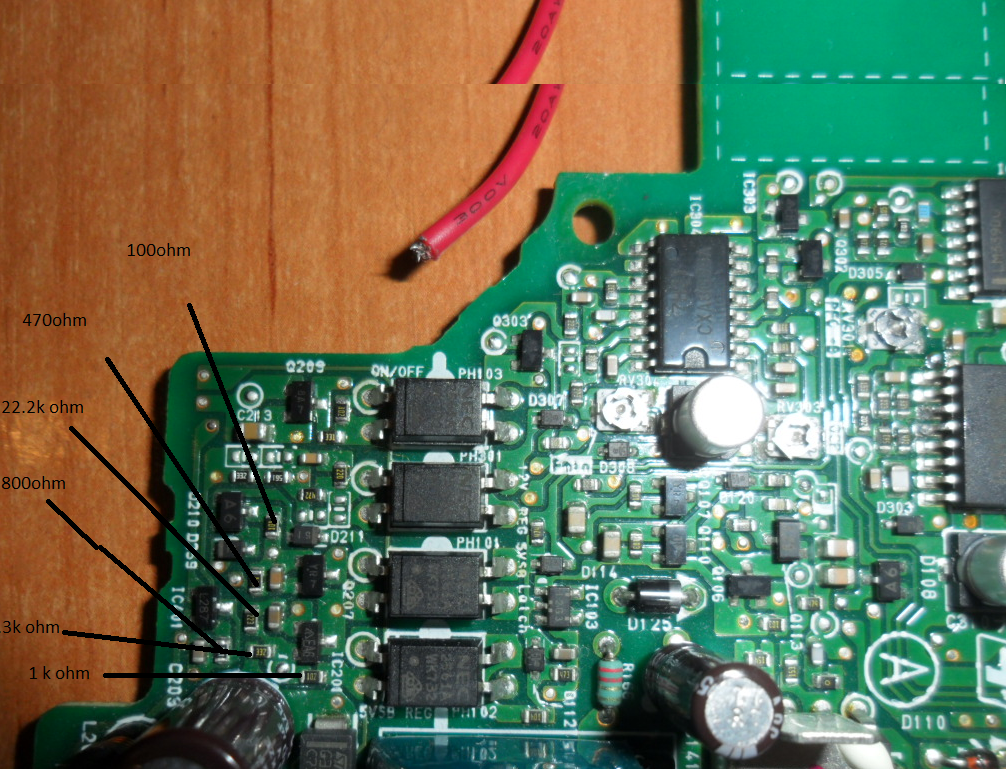
Like many of the SMPS units I’ve seen, the output voltage is controlled by referencing it to an adjustable shunt reference, and adjusting the set point of this reference will in turn adjust the output voltage of the supply, this is done in circuit by a single resistor.
Here’s the regulator section of the PSU, with the resistors labelled. The one we’re after changing is the 800Ω one between pins 2 & 3 of the TS2431 shunt reference. It’s a very small 0402 size resistor, located right next to the filter electrolytic for the 5v standby supply circuit. A fine tip on the soldering iron is required to get this resistor removed.
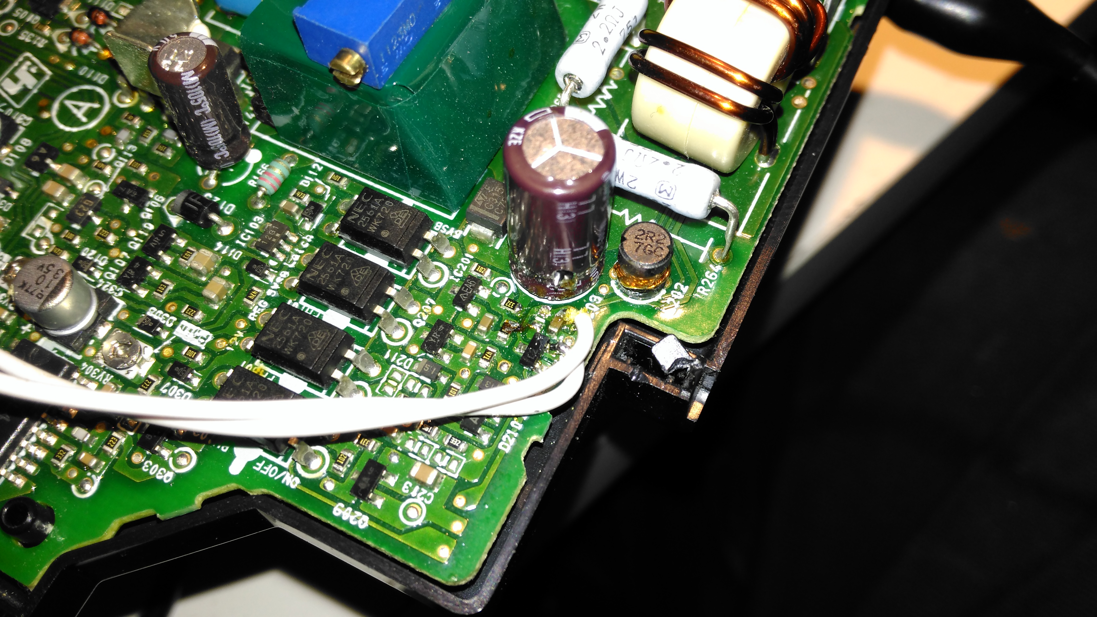
Attachment Points
Once this resistor is removed from the circuit, a 1KΩ 18-turn potentiometer is fitted in it’s place, from the Anode (Pin 3) to the Ref. (Pin 2) pins of the TS2431 shunt reference. I initally set the potentiometer to be the same 800Ω as the factory set resistor, to make sure the supply would start up at a sensible voltage before I did the adjustment.
Potentiometer
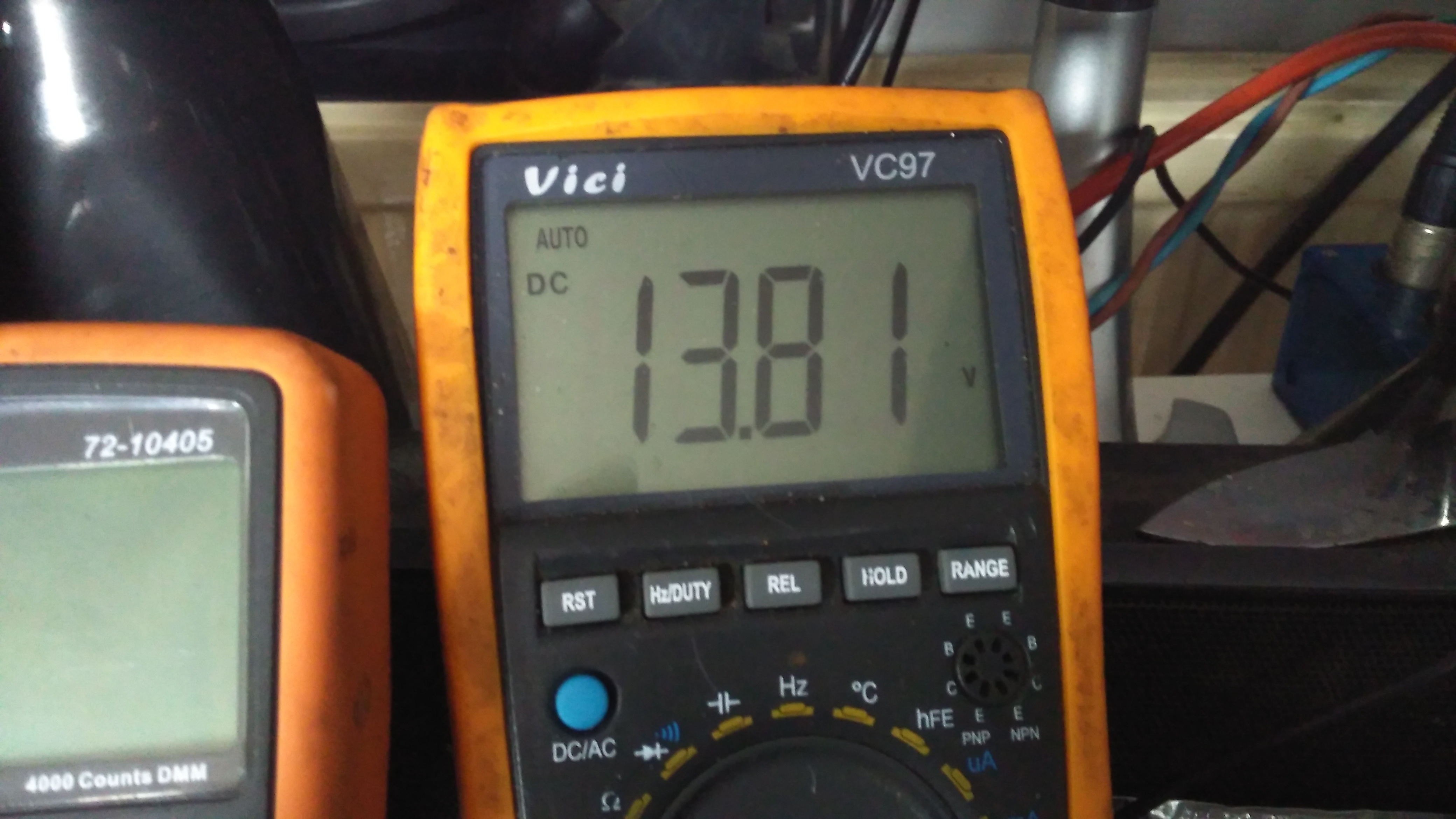
The pot is secured to the top of the standby supply transformer with a drop of CA glue to stop everything moving around. The supply can now be adjusted to a higher setpoint voltage – 13.8v is about the maxumum, as the OVP cuts the supply out at between 13.9v-14v.
Modded Voltage
After doing some testing at roughly 50% of the supply’s rated load, everything seems to be stable, and nothing is heating up more than I’d expect.
I’ve been running my own VPN so I can access my home-based servers from anywhere with an internet connection (not to mention, in this day & age of Government snooping – personal privacy & increased security).
I’m on a pretty quick connection from Virgin Media here in the UK, currently the fastest they offer:
Virgin Media
To do these tests, I used the closest test server to my VPN host machine, in this case Paris. This keeps the variables to a minimum. Testing without the VPN connection gave me this:
Paris Server Speed
I did expect a lower general speed to a server further away, this will have much to do with my ISP’s traffic management, network congestion, etc. So I now have a baseline to test my VPN throughput against.
The problem I’ve noticed with OpenVPN stock configs are that the connections are painfully slow – running over UDP on the usual port of 1194 the throughput was pretty pathetic:
Stock Config Speed
I did some reading on the subject, the first possible solution being to change the send/receive buffers so they’re set to a specific value, rather than letting the system handle them. I also added options to get the server to push these values to the clients, this saving me the trouble of having to reissue all the client configurations.
Unfortunately just this option didn’t work as well as I’d like, downstream speeds jumped to 25Mb/s. In the stock config, the tunnel MTU & MSSFIX settings aren’t bothered with, some adjustment to set the tunnel MTU to lower than the host link MTU (in my case the standard 1500) prevents packet fragmentation, MSSFIX let’s the client TCP sessions know to limit the packet sizes it sends so that after OpenVPN has done the encryption & encapsulation, the packets do not exceed the set size. This also helps prevent packet fragmentation.
tun-mtu 1400
mssfix 1360
VPN Tweaked
After adjusting these settings, the download throughput over the VPN link has shot up to 136Mb/s. Upload throughput hasn’t changed as this is limited by my connection to Virgin Media. Some more tweaking is no doubt possible to increase speeds even further, but this is fine for me at the moment.
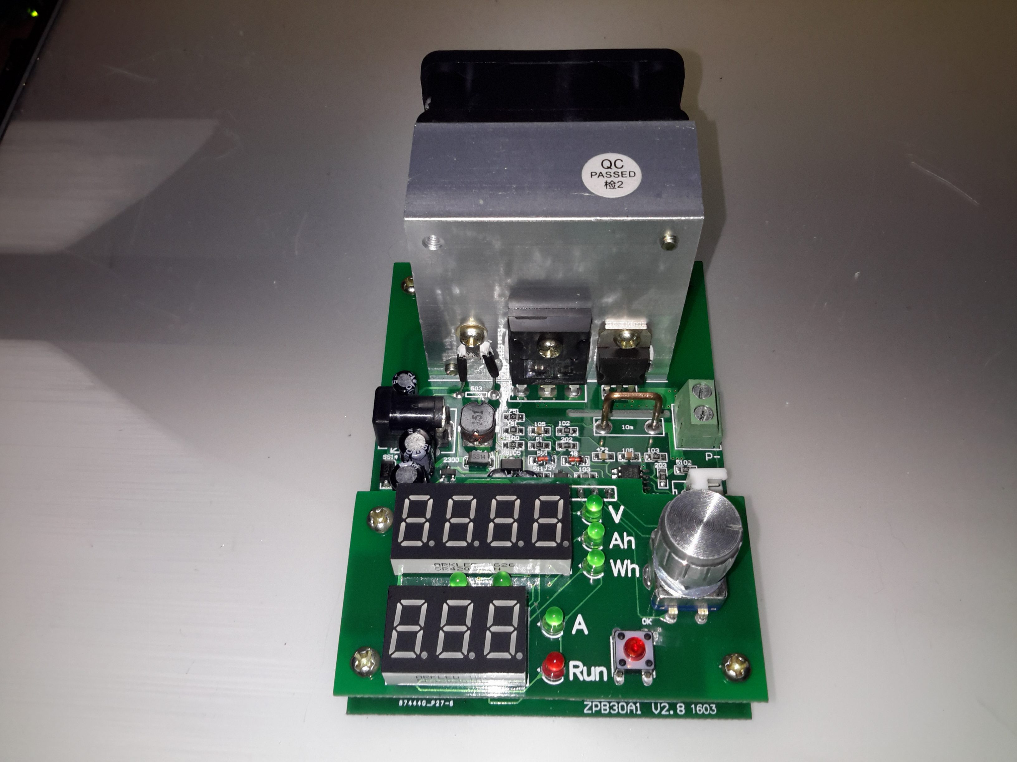
Here’s a useful tool for testing both power supplies & batteries, a dummy load. This unit is rated up to 60W, at voltages from 1v to 25v, current from 200mA to 9.99A.
This device requires a 12v DC power source separate from the load itself, to power the logic circuitry.
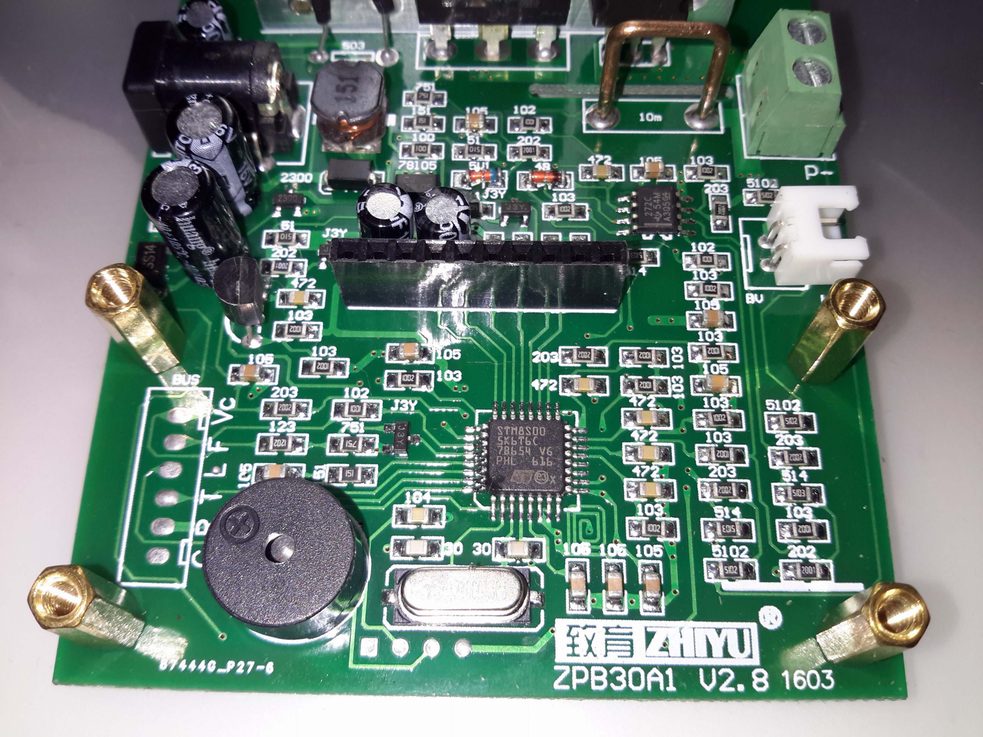
Microcontroller Section
Like many of these modules, the brains of the operation is an STM8 microcontroller. There’s a header to the left with some communication pins, the T pin transmits the voltage when the unit is operating, along with the status via RS232 115200 8N1. This serial signal is only present in DC load mode, the pin is pulled low in battery test mode. The 4 pins underneath the clock crystal are the programming pins for the STM8.
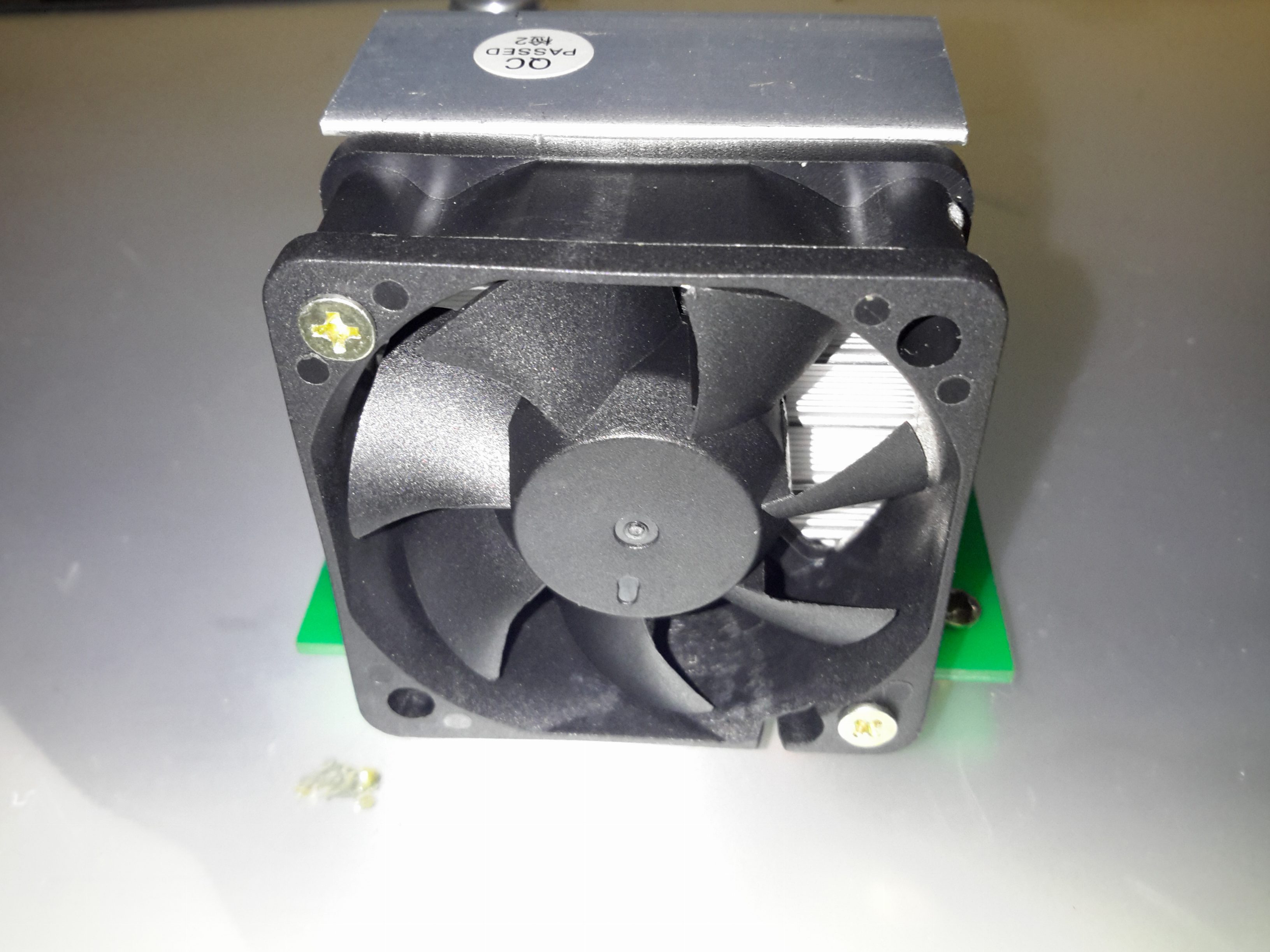
Serial CommsCooling Fan
The main heatsink is fan cooled, the speed is PWM controlled via the microcontroller depending on the temperature.
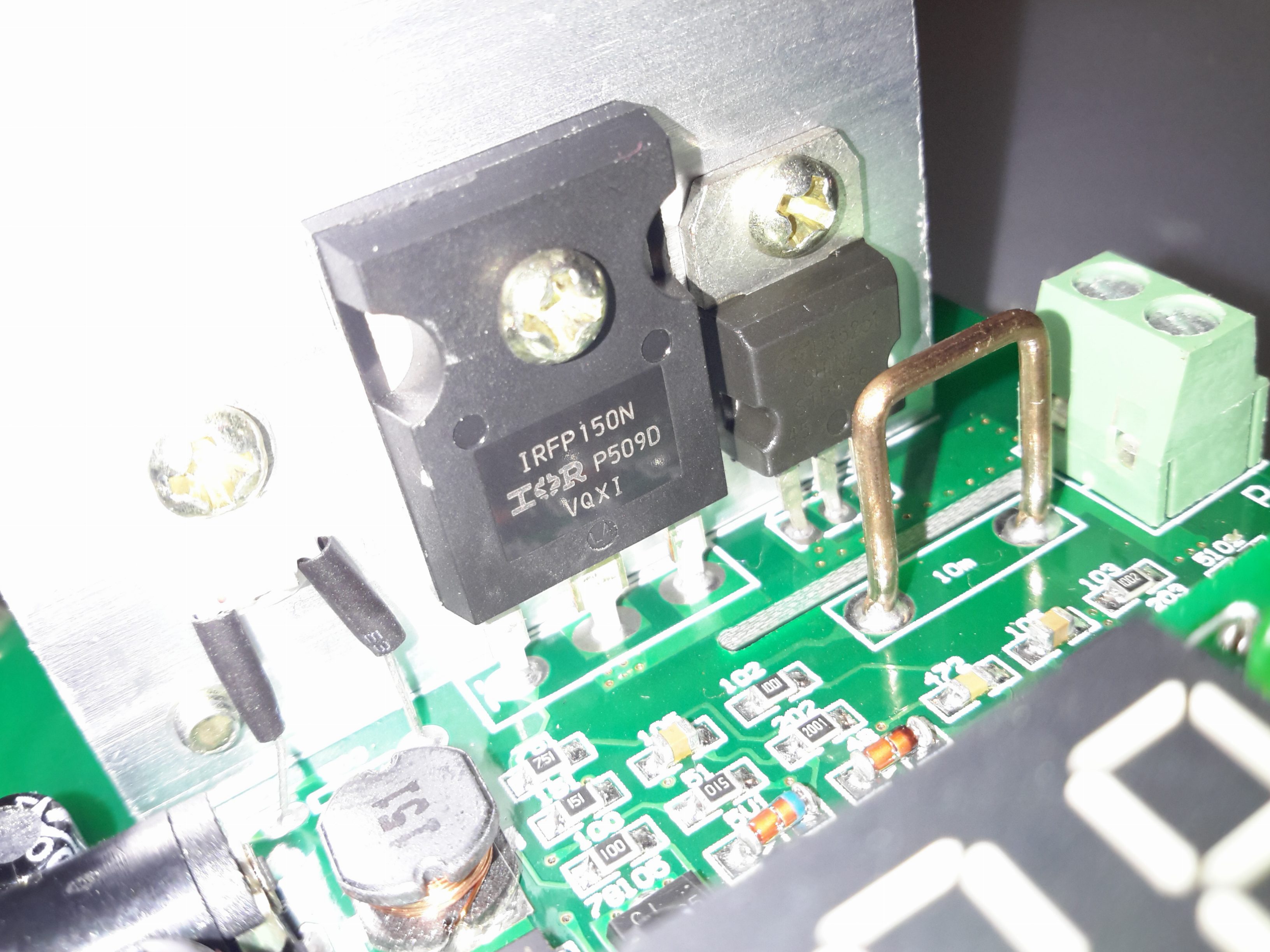
Main MOSFET
The main load MOSFET is an IRFP150N from Infineon. This device is rated at 100v 42A, with a max power dissipation of 160W. On the right is a dual diode for reverse polarity protection, this is in series with the MOSFET. On the left is the thermistor for controlling fan speed.
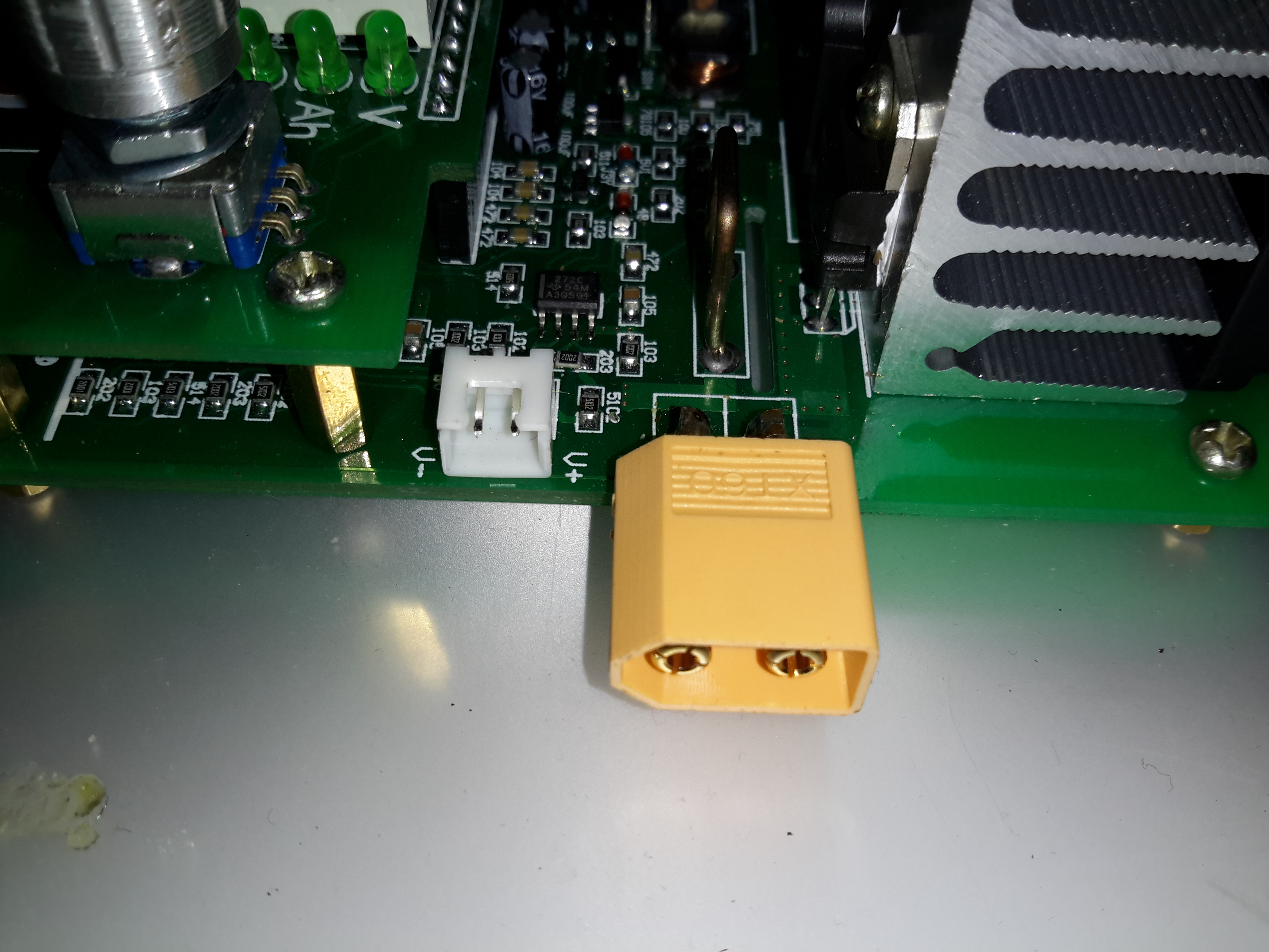
Load Terminals
The load is usually connected via a rising clamp terminal block. I’ve replaced it with a XT60 connector in this case as all my battery holders are fitted with these. This also removes the contact resistance of more connections for an adaptor cable. The small JST XH2 connector on the left is for remote voltage sensing. This is used for 4-wire measurements.
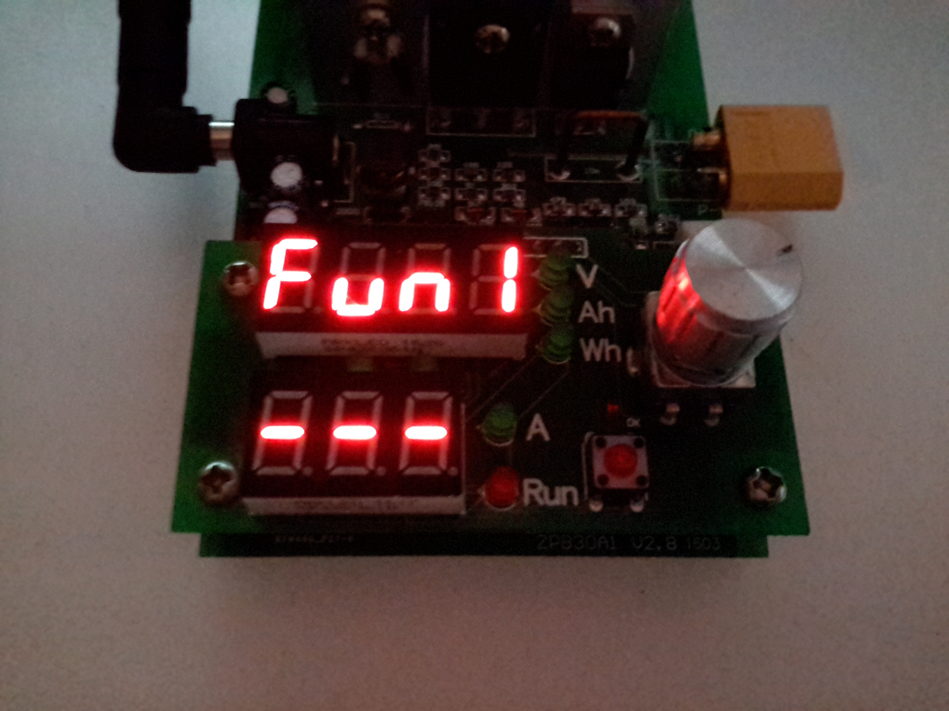
Function 1 – DC Load
Powering the device up while holding the RUN button gets you into the menu to select the operating modes. Function 1 is simple DC load.
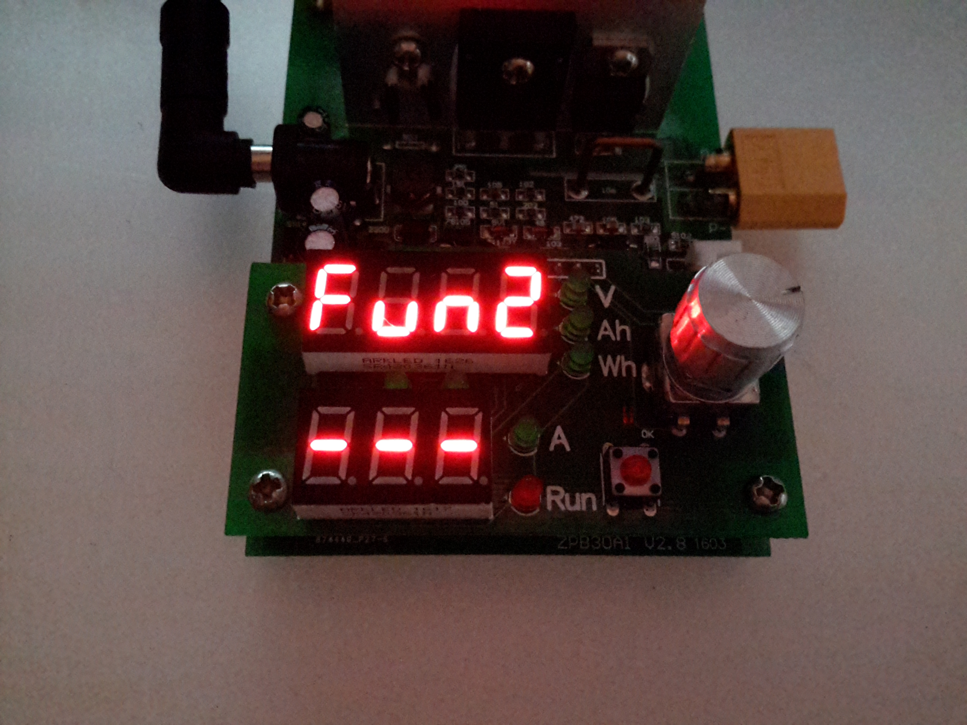
Function 2 – Battery Capacity Mode
The rotary encoder is used to select the option. Function 2 is battery capacity test mode.
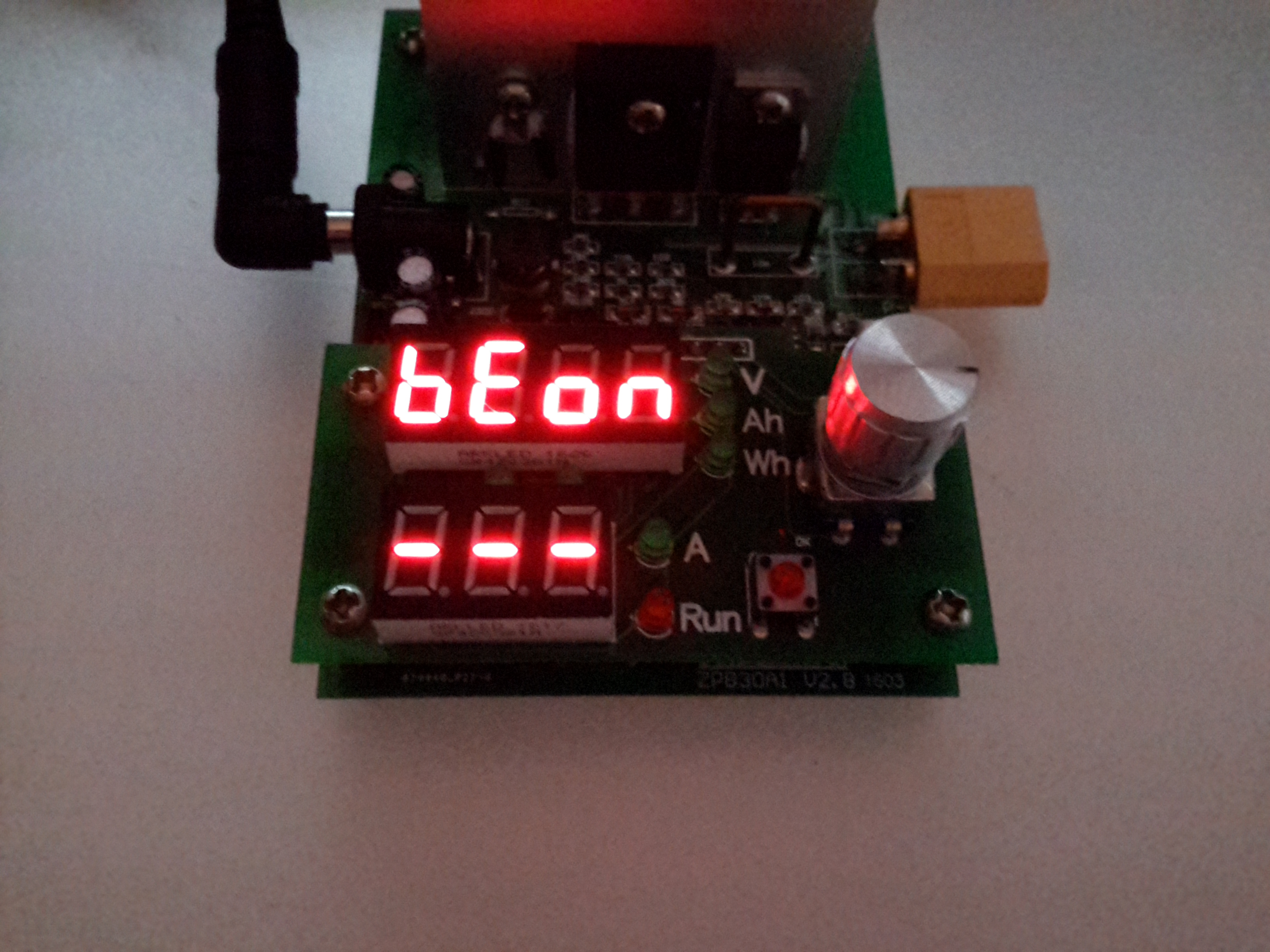
Beeper Mode
After the mode is selected, an option appears to either turn the beeper on or off.
Amps Set
When in standby mode, the threshold voltage & the load current can be set. Here the Amps LED is lit, so the load current can be set. The pair of LEDs between the displays shows which digit will be changed. Pressing the encoder button cycles through the options.
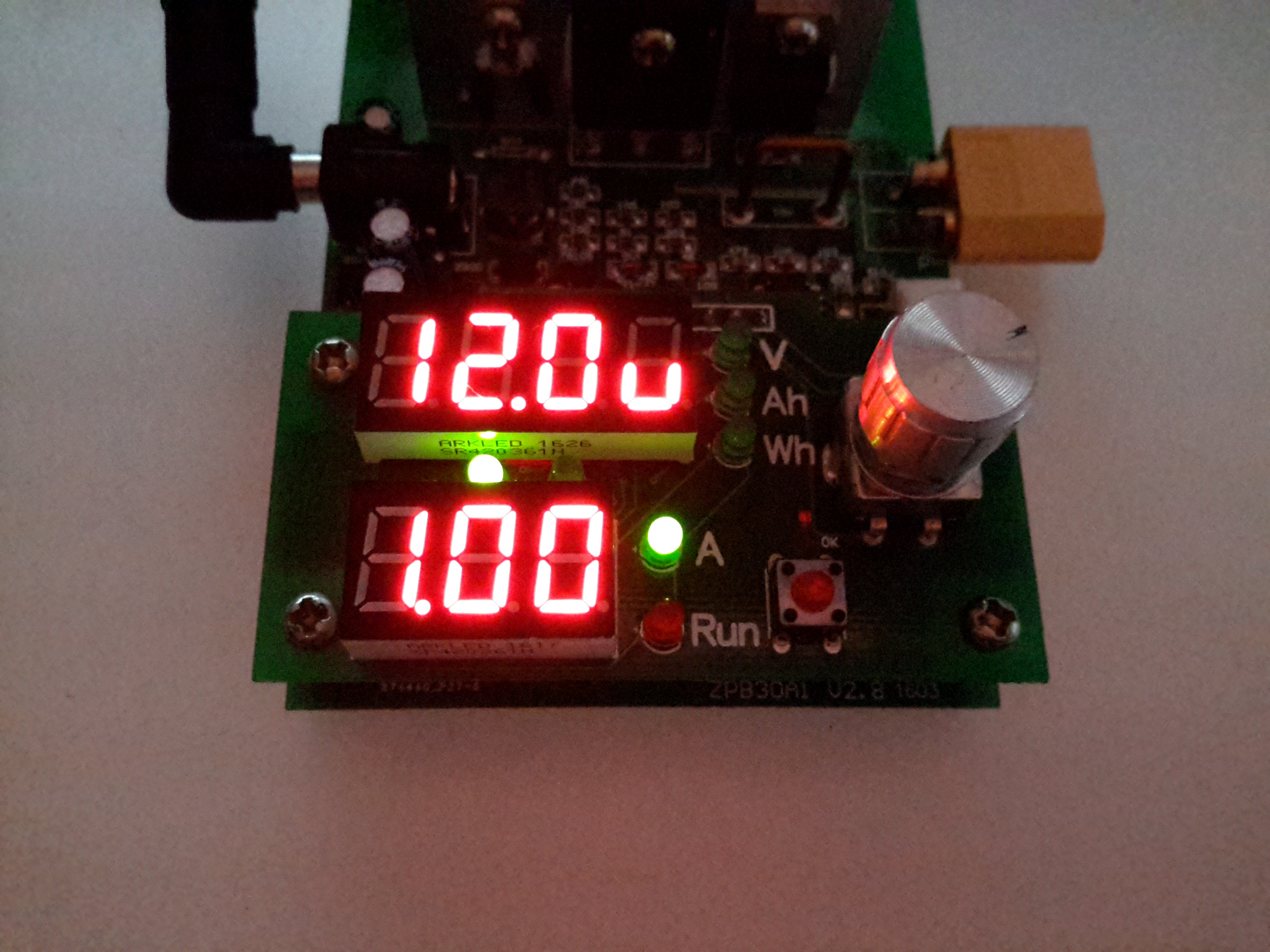
Volts Set
With the Volts LED lit, the threshold voltage can be changed.
When in DC load mode (Fun1), the device will place a fixed load onto the power source until it’s manually stopped. The voltage setting in this mode is a low-voltage alarm. The current can be changed while the load is running.
When in battery discharge test mode (Fun2), the voltage set is the cutoff voltage – discharge will stop when this is reached. Like the DC load mode, the current can be changed when the load is running. After the battery has completed discharging, the capacity in Ah & Wh will be displayed on the top 7-segment. These results can be selected between with the encoder.
Below are tables with all the options for the unit, along with the error codes I’ve been able to decipher from the Chinese info available in various places online. (If anyone knows better, do let me know!).
Option
Function
Fun1
Basic DC Load
Fun 2
Battery Capacity Test
BeOn
Beeper On
BeOf
Beeper Off
Error Code
Meaning
Err1
Input Overvoltage
Err2
Low Battery Voltage / No Battery Present / Reverse Polarity
Err3
Battery ESR Too High / Cannot sustain selected discharge current
Err4
General Failure
Err6
Power Supply Voltage Too Low / Too High. Minimum 12v 0.5A.
It’s been a while since I’ve done a proper radio based post, so it’s a bit of a shame that I have to start off with a rant, but it’s required in this case.
One of the local 70cm repeaters, GB3WP seems to have many problems. The largest one seems to be G6YRK, the repeater keeper.
I had heard rumours of the repeater suddenly going off air getting switched off when either an M3/M6 or 2E0/2E1 was using it. At the time I thought no fellow ham could be quite that petty.
What callsign I or anybody else has should not make a shred of difference whether we should be allowed on the air or not. I personally keep my operating standards as high as possible, way above and beyond what Ofcom stipulates in the licence terms, as it’s part of making the hobby enjoyable for everyone. Seems that not everyone feels the same (in my experience, the older generation of hams, some of whom believe that the tests these days are far too easy, etc, etc).
Then I got proved wrong.
I was doing some handheld radio testing with M3HHY over at Distant Signal Radio on GB3WP, as at the time GB3MR was having some issues with the local pirate (see my previous posts for more info on that prat).
Within a couple of minutes of us establishing a QSO, the repeater suddenly stopped responding. After trying to get back in for a good 15 minutes, it came back on air again.
The instant we gave our callsigns, off it went, into the ether. No response.
This behaviour continued for nearly an hour, and after trying to contact YRK directly, we gave it up as a bad job, with quite a bit of pissed off added into the mix.
If I’d not heard stories of the repeater being turned off when the “wrong people” are using it, I might have put it down to dodgy repeater equipment, but even that didn’t make sense, as it had a definite pattern.
We both fired off an email to the Repeater Keeper, only to get no response from that either (surprise, surprise).
That was the last time I personally attempted to make use of GB3WP.
Until I was given an audio clip of G6YRK in action this evening.
Seems that not even M0 calls are immune from being wiped off the air by GB3WP. Chris, M0OGG, has apparently also had this issue with the repeater. Lucky for him, he had the opportunity to speak to the keeper directly about what went on.
Here’s the audio, I’ll pick each part out & go into a few opinions/observations below.
So, Chris (M0OGG) has asked a simple question, and been met with hostility. Dick Move Number 1.
YRK is clearly reluctant to go into “detail” on the air. Probably because he’s talking complete shite. Only when Lewis (M3HHY) joins in with a slightly more defensive tone does Steve (G6YRK) actually say what Chris has been “reported” for.
After all that it seems that an accusation of keying over other repeater users is the bullshit line of the day. (For the record, I know Chris, he’s not the type of person to key over another radio user, that behaviour in of itself is idiotic).
Apparently he has witnesses to this action, and he’s insisting that others were also involved. Not to mention the fact that RDF has been done on (I’m assuming) all of these “offenders”. G6YRK must have quite the army of hams with lots of spare time.
I’m not sure who the other station is, as he doesn’t give a callsign.
As Lewis jumps in & comments, the Repeater Keeper should be saying something to users he suspects of this kind of thing, in my opinion.
The real reason, of course, that he keeps turning the repeater off when others are using it is that he’s a passive-aggressive vindictive moron.
Surprise, surprise, he can’t remember the “exact date”, (because it never actually happened), it’s just “the other day, somebody did it”. Yeah, great evidence there Steve, because apparently the only person around at the time was Chris. How can he know this? When a repeater has a coverage area as wide as GB3WP, this guy is claiming that he knows that only a single person is listening? No, I think it’s bullshit too.
GB3WP Coverage Map
For reference, here’s the coverage map of the repeater. Steve G6YRK must be bloody psychic to make such a comment.
He then mentions a “friend” of Chris, but again refuses to give any names. Again I’m calling bullshit.
Swifty following this he goes into full kick-my-toys-out-of-the-pram mode because he’s been openly challenged.
While he’s correct in his statement that he can do as he pleases with the repeater, it’s not very good form to just switch the thing off when licenced users are having a perfectly valid QSO. If he doesn’t like people using the repeater, he should turn it off permanently & remove the listing from the repeater group.
After this, Steve makes the comment that he knows nothing of the repeater going off, as he’s been out all night. He mentions his Repeater Stasi again, and then makes a partial retraction of his previous statement, now that it “might” not have been Chris previously. Well Steve, we’re finally getting towards something that resembles truth. You’ve got absolutely no idea who is “keying people out”, if it’s even happening at all. So much for “having people all over the place” listening to where transmissions are coming from.
After Chris confronts him again, he returns to the fallback of that as the NoV holder it’s his prerogative to be able to switch the repeater off whenever he pleases.
When confronted with the fact that people pay into the repeater group to help keep them running, he claims that Chris’ signal is breaking up. My arse. Every other station on the repeater can hear him fine.
There’s probably more to add to this, so if I get any more relevant information from other sources I’ll add on to the saga.
I’m still on my crusade of removing every trace of 240v mains power from my shack, so next up are my computer monitors.
I have 4 Dell monitors, of various models, hooked up to my main PC.
The monitor here is a Dell E207WFPc 20″ widescreen model. There will be more when I manage to get the others apart to do the conversion. However I’m hoping that the PSU boards are mostly the same.
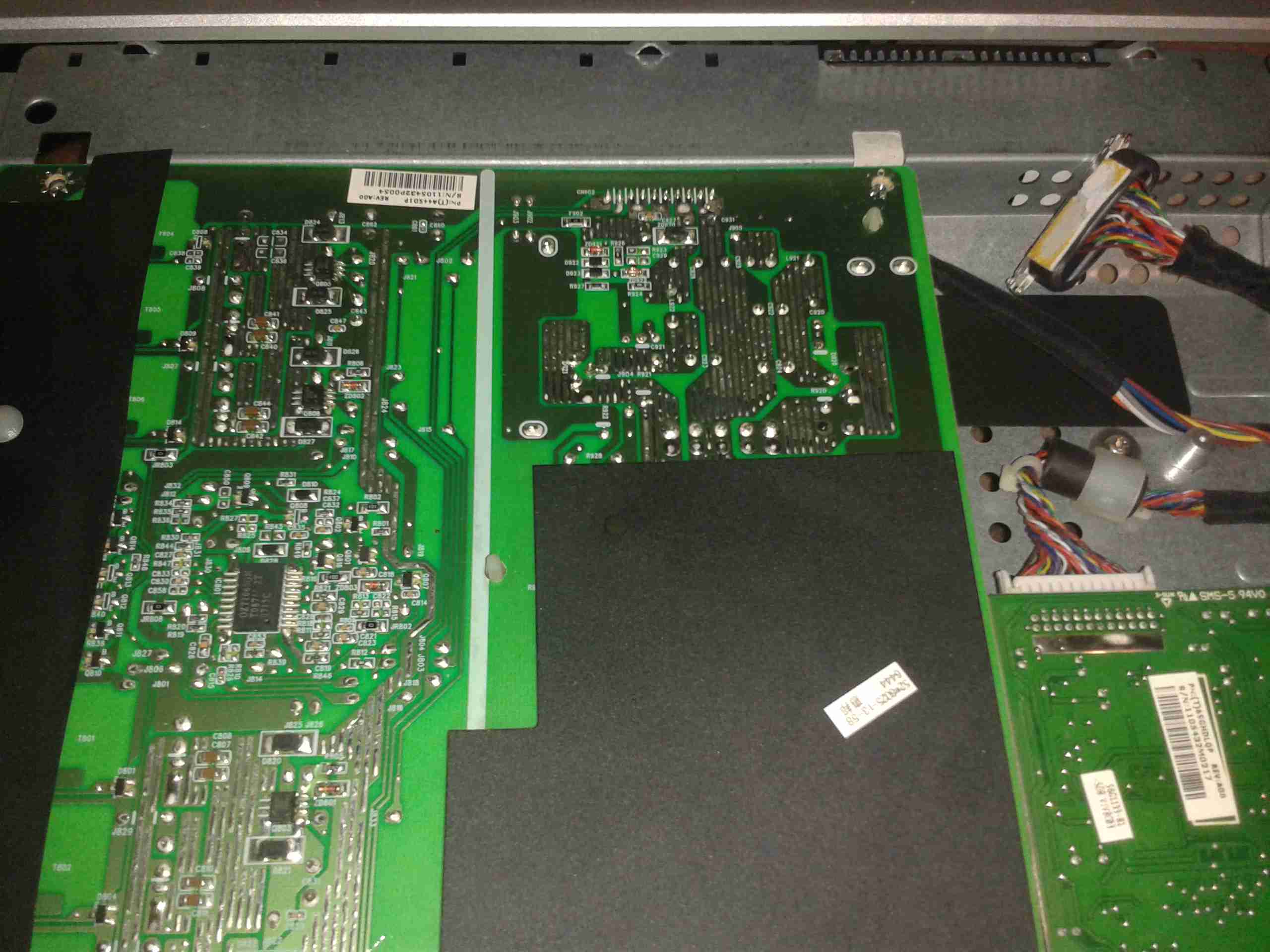
Panel Removed
There are no screws holding these monitors together, the front bezel is simply clicked into place in the back casing, these clips are the only thing that holds the relatively heavy glass LCD panel & it’s supporting frame! The image above shows the panel removed. The large board on the left is the power supply & backlight inverter, the smaller one on the right is the interface board to convert the DVI or VGA to LVDS for the LCD panel itself.
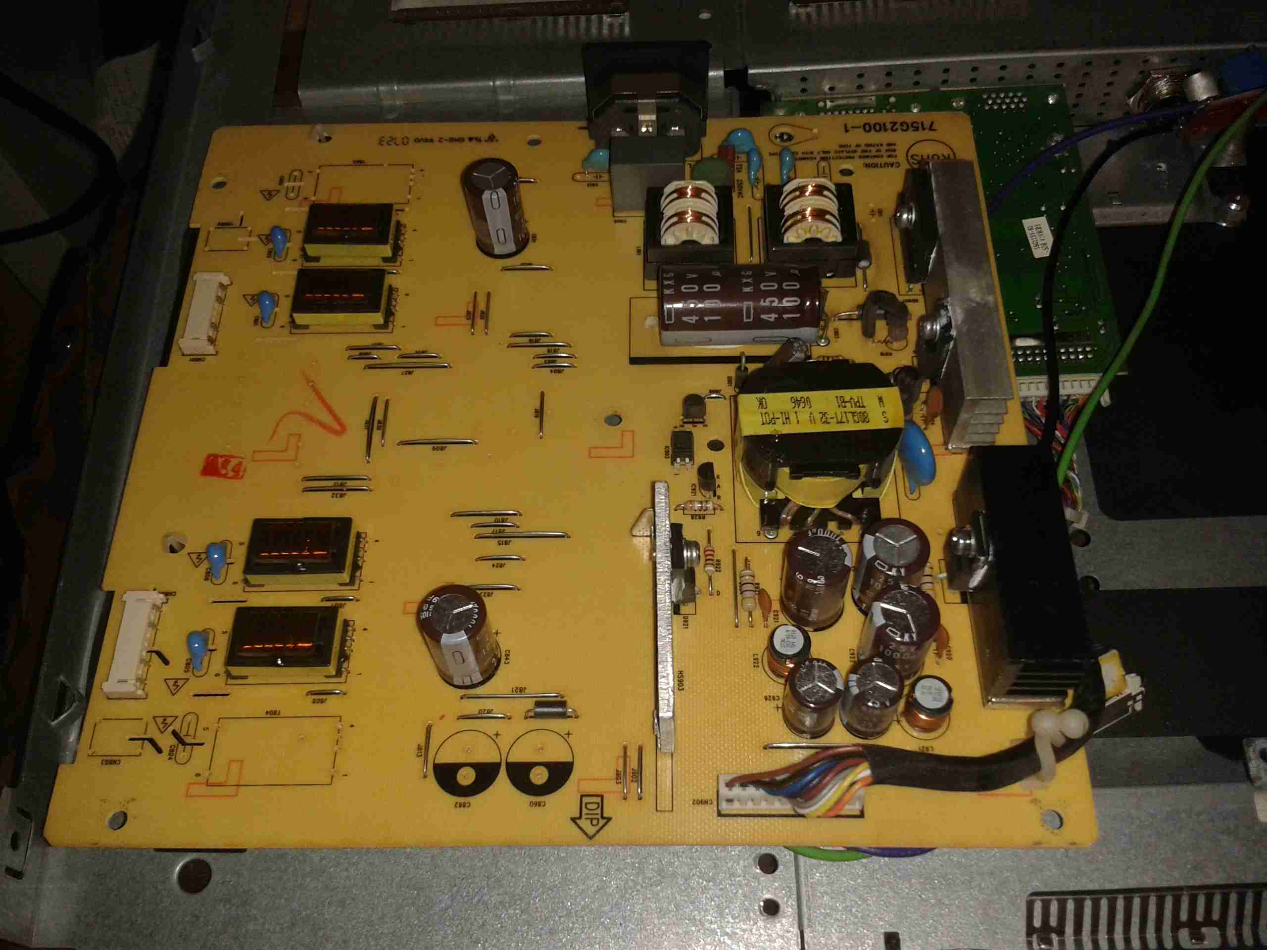
PSU Board
Here’s a closeup of the PSU board, the connector at centre right at the top of the PCB is the main power output, and also has a couple of signals to control the backlight inverter section of the PSU, on the left side. The PSU requirements for this monitor are relatively simple, at 14.5v for the backlight & 5v for the logic board.
PSU
Here’s the top of the PSU board, very simple with the mains supply on the right side, and the backlight inverter transformers on the left.
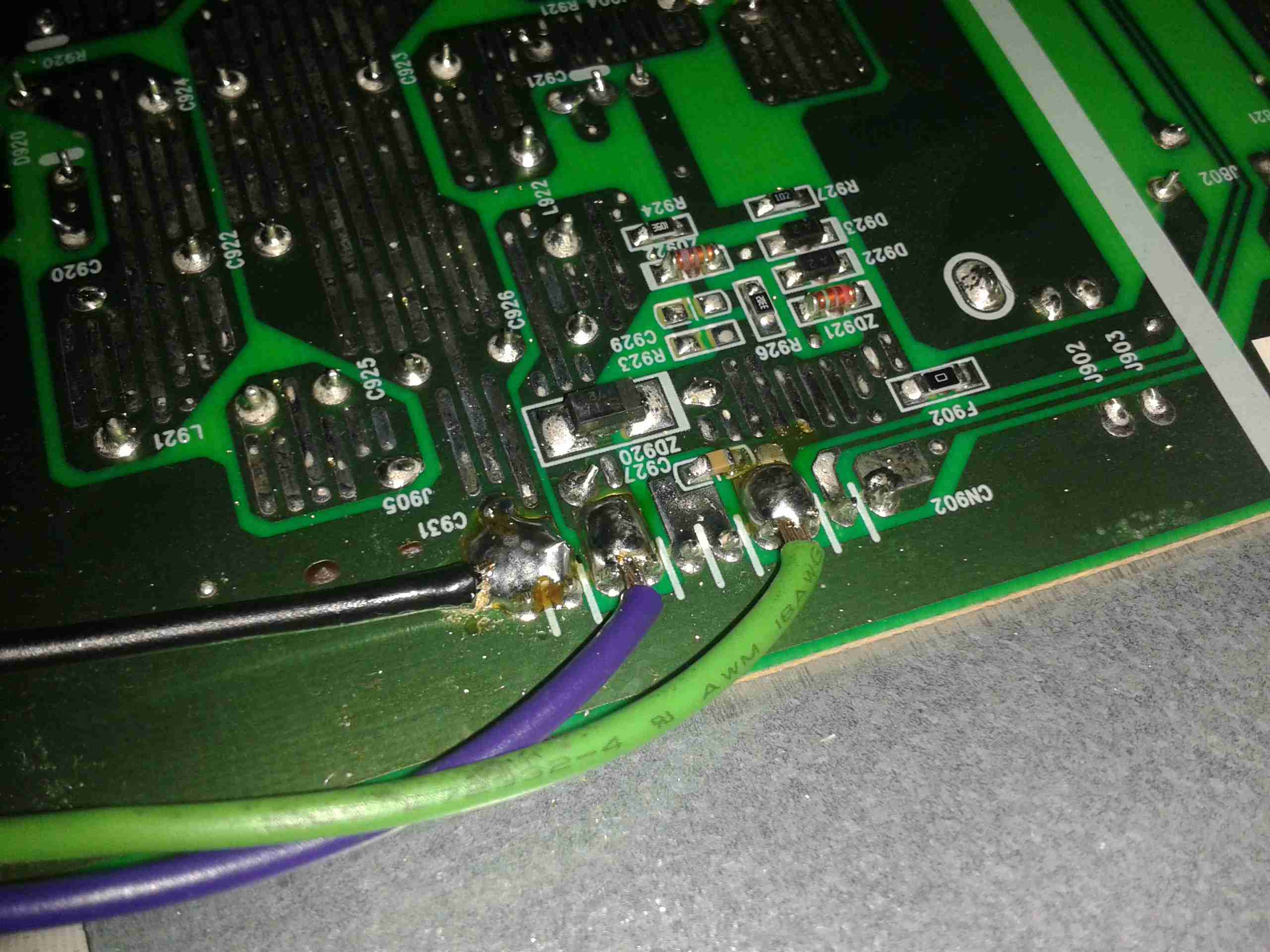
Hooked In
Here I’ve hooked into the power rails on the supply, to attach my own 12v regulators. The green wire is +14.5v, and the purple is +5v. Black is common ground.
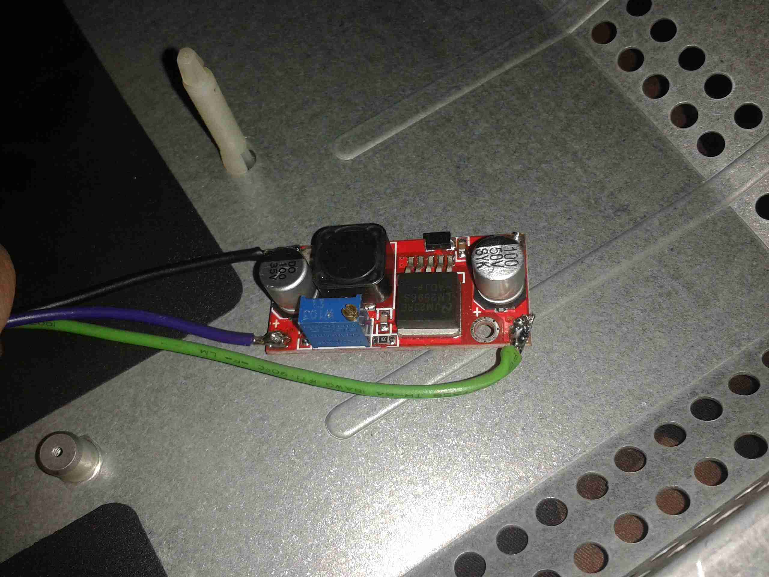
5v Regulator
On doing some testing, the backlight inverter section doesn’t seem to mind voltages between 11.5-14.5v, so a separate regulator isn’t required there. Even running off batteries that’s within the range of both charging & discharging. The only regulator required is a 5v one to reduce the input voltage for the logic PCB.
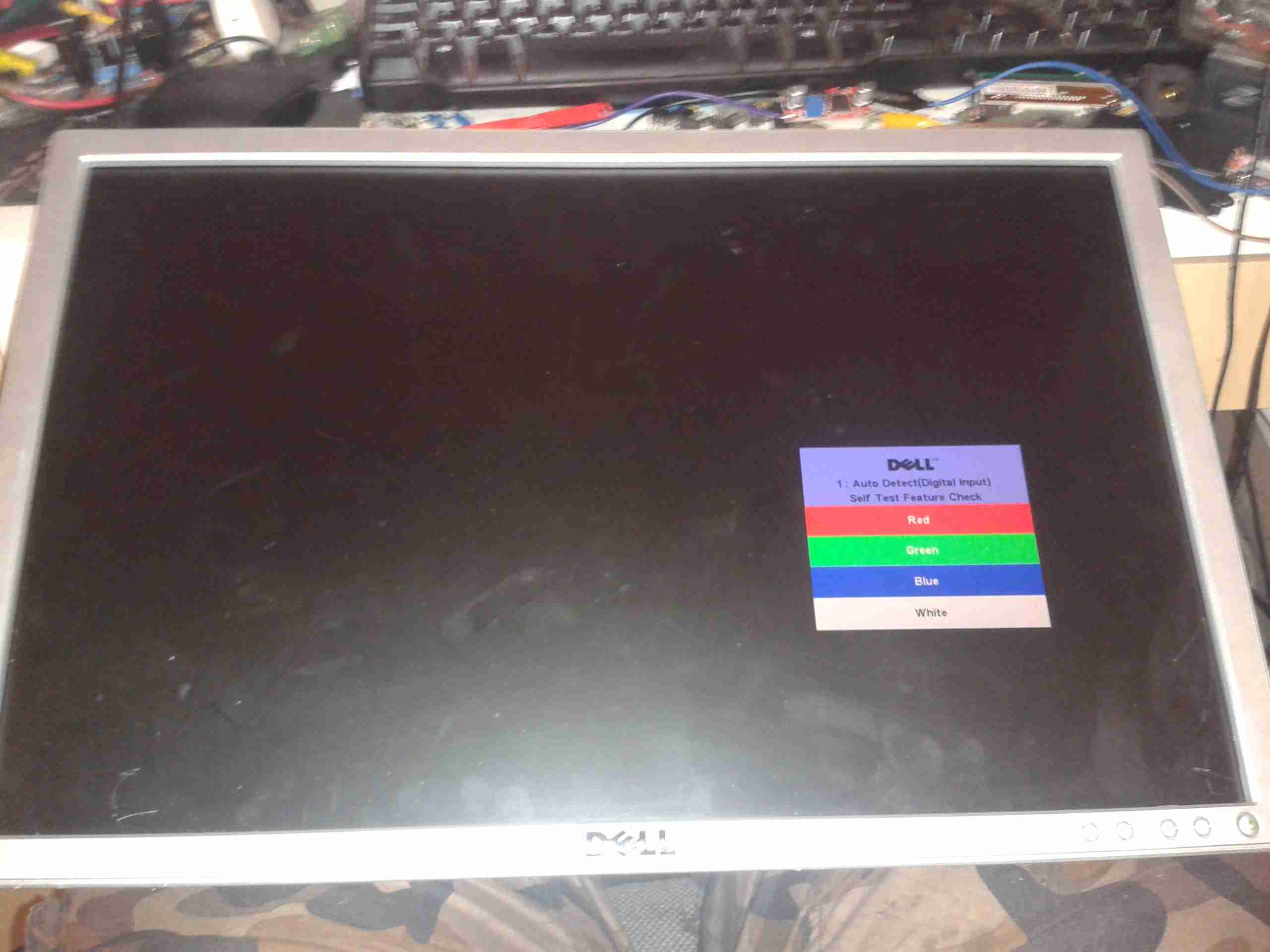
First Test
On applying some 12v power to the regulator input, we have light! Current draw at 12.5v is 2.65A for a power consumption of 33W.
12v Input
There’s plenty of room in the back casing to mount a 12v input socket, I have left the mains supply intact so it can be used on dual supply.
Final Wiring
Here’s the 5v regulator mounted on the back of the casing, all wired up & ready to go.
Here’s some testing of the first bipolar supply for the Rigol scope. This is the +/-7.5v supply.
Bipolar Supply
Above is the supply built with it’s output filtering. The modules used are a PTN78020W for the positive rail & a PTN78060A for the negative rail.
Under a 1A load across the total 15v output, here’s some scope traces of the ripple on the supply:
+7.5v Rail
Here’s the ripple on the +7.5v rail of the supply, there’s about 75mV of total ripple.
-7.5v Rail
And here’s the -7.5v rail, the ripple on this is slightly lower, at about 50mV. This should be more than satisfactory as the scope has onboard linear regulation after the switching supply.
I’ve noticed that the RF power output from the Chinese radios can be quite variable from model to model, and even from individual radios of the same model & batch.
I’ve bought an RF Power meter (GY561) to do some tests on the HTs I have at present.
All tests were performed with the radio fully charged & still on the charging base, to make sure the supply voltage remained constant at 8.4v throughout the tests.
Frequencies used were 145.500 & 433.500 for VHF & UHF respectively.
The power meter was connected with ~8″ of RG174 Coax.
I recently posted about a small analog SWR/Power meter I got from eBay, and figured it needed some improvement.
After some web searching I located a project by ON7EQ, an Arduino sketch to read SWR & RF power from any SWR bridge.
The Arduino code is on the original author’s page above, his copyright restrictions forbid me to reproduce it here.
I have also noticed a small glitch in the code when it is flashed to a blank arduino: The display will show scrambled characters as if it has crashed. However pushing the buttons a few times & rebooting the Arduino seems to fix this. I think it’s related to the EEPROM being blank on a new Arduino board.
I have run a board up in Eagle for testing, shown below is the layout:
SWR Meter SCH
The Schematic is the same as is given on ON7EQ’s site. Update: ON7EQ has kindly let me know I’ve mixed up R6 & R7, so make sure they’re switched round when the board is built ;). Fitting the resistors the wrong way around may damage the µC with overvoltage.
SWR Meter PCB
Here’s the PCB layout. I’ve kept it as simple as possible with only a single link on the top side of the board.
PCB Top
Here’s the freshly completed PCB ready to rock. Arduino Pro mini sits in the center doing all the work.
The link over to A5 on the arduino can be seen here, this allows the code to detect the supply voltage, useful for battery operation.
On the right hand edge of the PCB are the pair of SMA connectors to interface with the SWR bridge. Some RF filtering is provided on the inputs.
PCB Bottom
Trackside view of the PCB. This was etched using my tweaked toner transfer method.
LCD Fitted
Here the board has it’s 16×2 LCD module.
Online
Board powered & working. Here it’s set to the 70cm band. The pair of buttons on the bottom edge of the board change bands & operating modes.
As usual, the Eagle layout files are available below, along with the libraries I use.
[download id=”5585″]
[download id=”5573″]
More to come on this when some components arrive to interface this board with the SWR bridge in the eBay meter.
The original LM2577 based regulators I designed into my mobile battery pack turned out to be insufficient for requirements, therefore they have been replaced with higher capacity regulators.
The 12v regulator (left) is a muRata UQQ-12/8-Q12P-C SEPIC converter, providing a max of 8A at 12.1v DC. The 12v rail is also now independently switchable to save power when not in use.
The 5v regulator (right) is a Texas Instruments PTN78020WAZ switching regulator, rated at 6A. The pair of resistors on the back of the regulator set the output voltage to 5.1v.
Also a new addition is a pair of banana sockets & a 2.1mm DC jack, wired into the 12v DC bus, for powering various accessories.
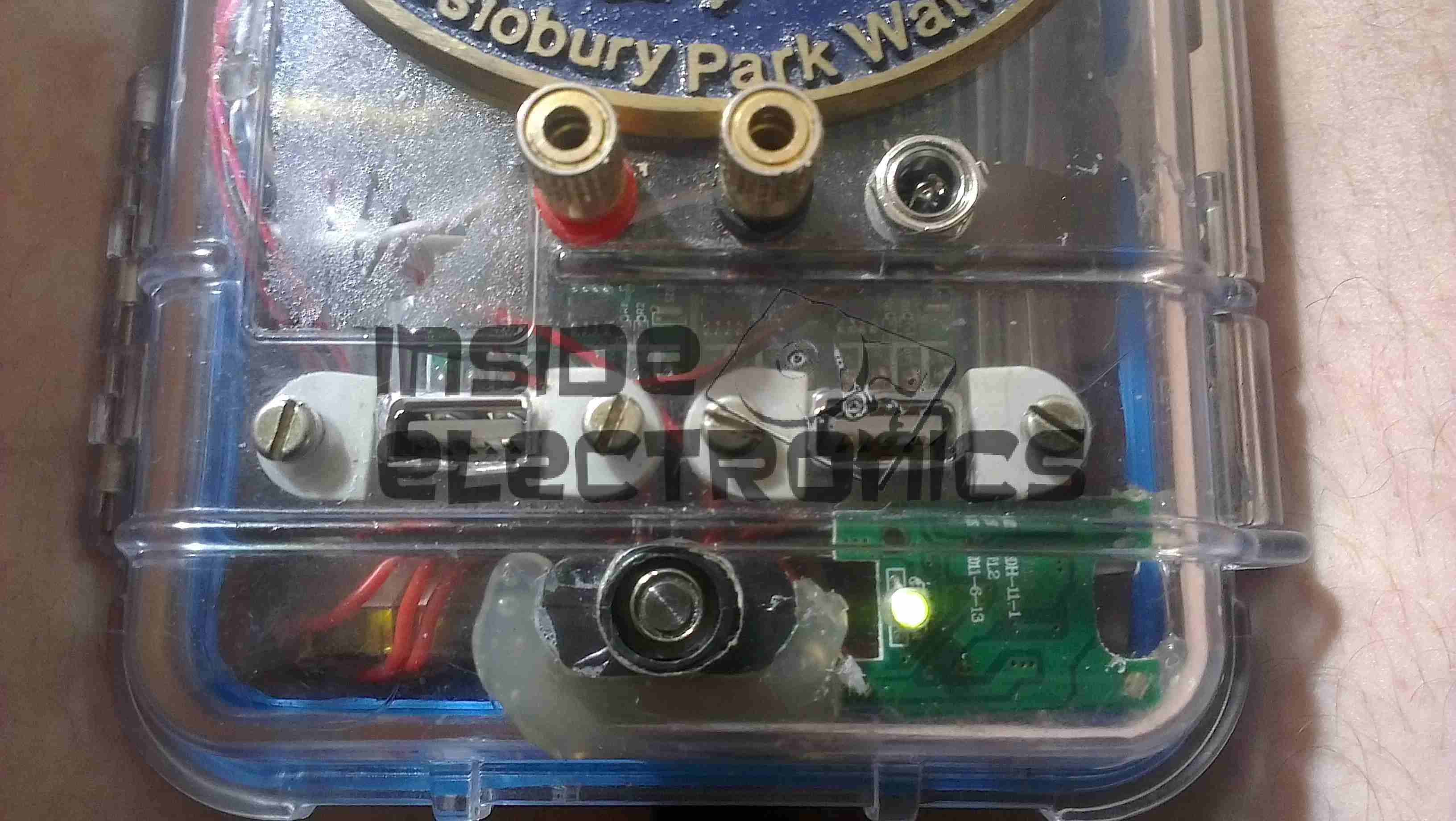
New Additions
Below the USB sockets is now a built in eCig charger, to save on USB ports while charging these devices.
IWA National Festival 2013
These changes were made after much field testing of the unit at Cassiobury Park, Watford, for the IWA National Waterways Festival.
Progress is finally starting on the power supply unit for the Pi, fitted into the same case style as the Pi itself, this is an 8Ah Li-Poly battery pack with built in voltage regulation.
Regulator Boards
Here are the regulators, fixed to the top of the enclosure. These provide the 12v & 5v power rails for the Pi unit, at a max 3A per rail.
Battery Pack
In the main body of the case the battery pack is fitted. This is made up of 4 3-cell Li-Poly RC battery packs, rated at 2Ah each. All wired in parallel this will provide a total of 8Ah at 12.6v when fully charged.
Powered Up
Here the regulators are powered up from a 13v supply for testing. I have discovered at full load these modules have very bad ripple, so I will be adding extra smoothing capacitors to the power rails to compensate for this.
I/O
Here are the connectors on the top of the unit, outputting the two power rails to the Pi & the DC barrel jack that will be used to charge the pack.
Here are a few details of a valve amplifier I am building, using the valve related parts from a 1960’s reel to reel tape recorder.
This amplifier is based on an a Mullard ECL82 triode/pentode valve, with an EM84 magic eye tube for level indication.
Beginnings Of The Amplifier
Here the first components are being soldered to the tags on the valve holder, there are so few components that a PCB is not required, everything can be rats-nested onto the valve holders.
Progress
Progressing with the amplifier section componentry, all resistors are either 1/2W or 2W.
Valve Sockets Fitted
Here the valve holders have been fitted, along with the output transformer, DC smoothing capacitor & the filament wiring, into the top of the plastic housing. At this point all the components that complete the amplifier section are soldered to the bottom of the right hand valve holder.
Wiring
Starting the wiring between the valves & the power supply components. The volume control pot is fitted between the valve holders.
Valves Test Fit
The valves here are test fitted into their sockets, the aluminium can at the back is a triple 32uF 250v electrolytic capacitor for smoothing the B+ rail.
Amplifier Section First Test
First test of the amplifier, with the speaker from the 1960’s tape recorder from which the valves came from. the 200v DC B+ supply & the 6.3v AC filament supply is derived from the mains transformer in the background.
Magic Eye Tube Added
Here the magic eye tube has been fitted & is getting it’s initial tuning to the amplifier section. This requires selecting combinations of anode & grid resistors to set the gap between the bars while at no signal & picking a coupling RC network to give the desired response curve.
Final Test
Here both valves are fitted & the unit is sitting on it’s case for final audio testing. the cathodes of the ECL82 can be clearly seen glowing dull red here.
In the final section, I will build a SMPS power supply into the unit to allow it to be powered from a single 12v DC power supply.
Here I will document progress in replacing standard halogen MR10 lights with LEDs.
3x1W LED
These units are from TruOpto, available through Rapid Electronics in the UK. They are 3W total, from 3x 1W emitters on an aluminium back plate.
LED Test Rig
Here is the LED attached to a heatsink for testing purposes – these units dissipate nearly 2W in heat at full output.
As the lights are to be run from a 12v battery bank, for simplicity a master regulator is required to provide a stable 11.4v rail for LED supply.
Regulator Module
I have used a Texas Instruments part – PTN78020WAH. This is a 6A capable adjustable regulator module.
The LED lights are to be fully dimmable – the low voltage PWM dimmers are in progress of being built.
Tip Jar
If you’ve found my content useful, please consider leaving a donation by clicking the Tip Jar below!
All collected funds go towards new content & the costs of keeping the server online.