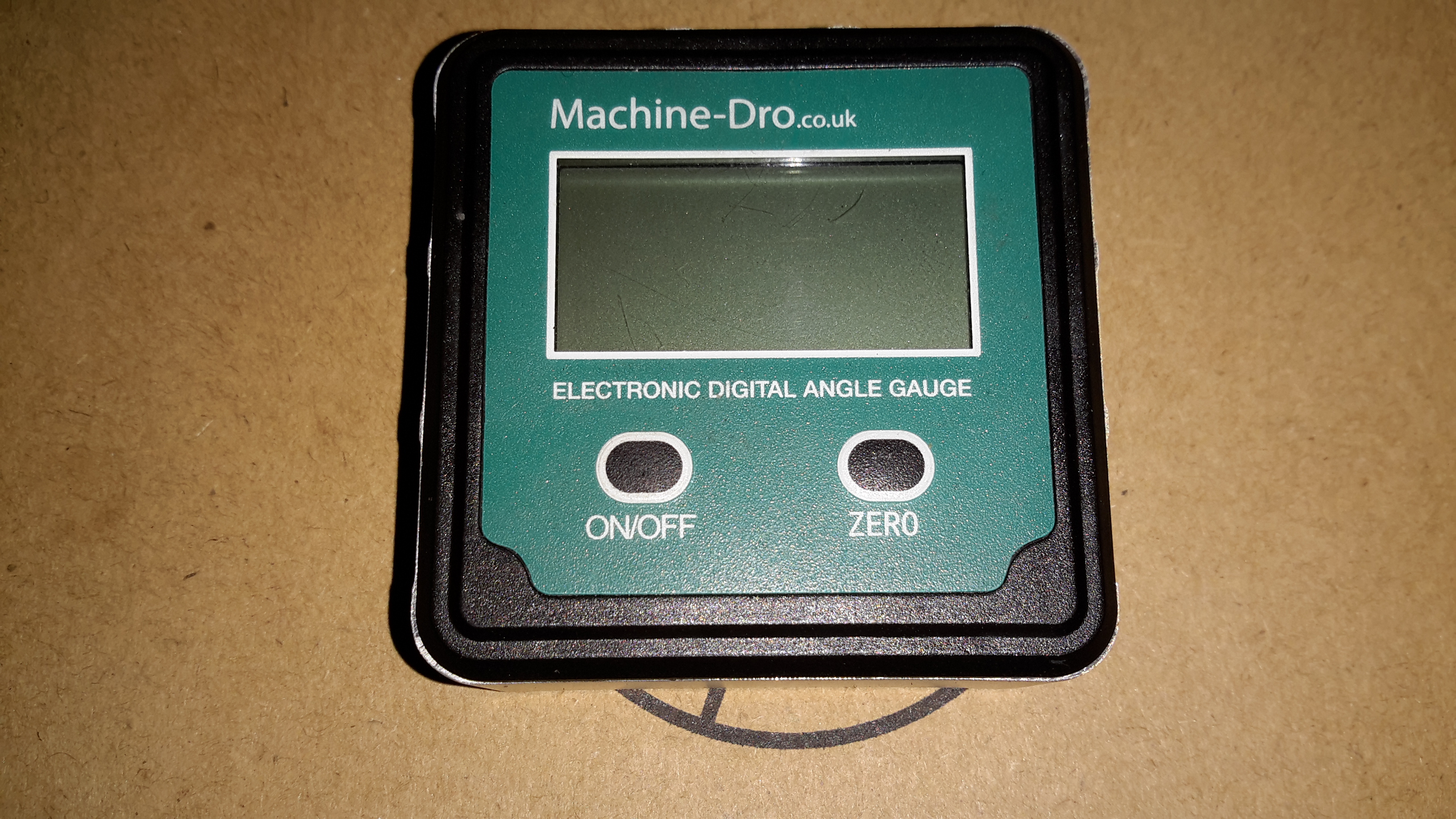
Here’s a useful tool for the kit, a digital angle gauge/protractor. These use a silicon sensor to show the number of degrees the unit is out of level.
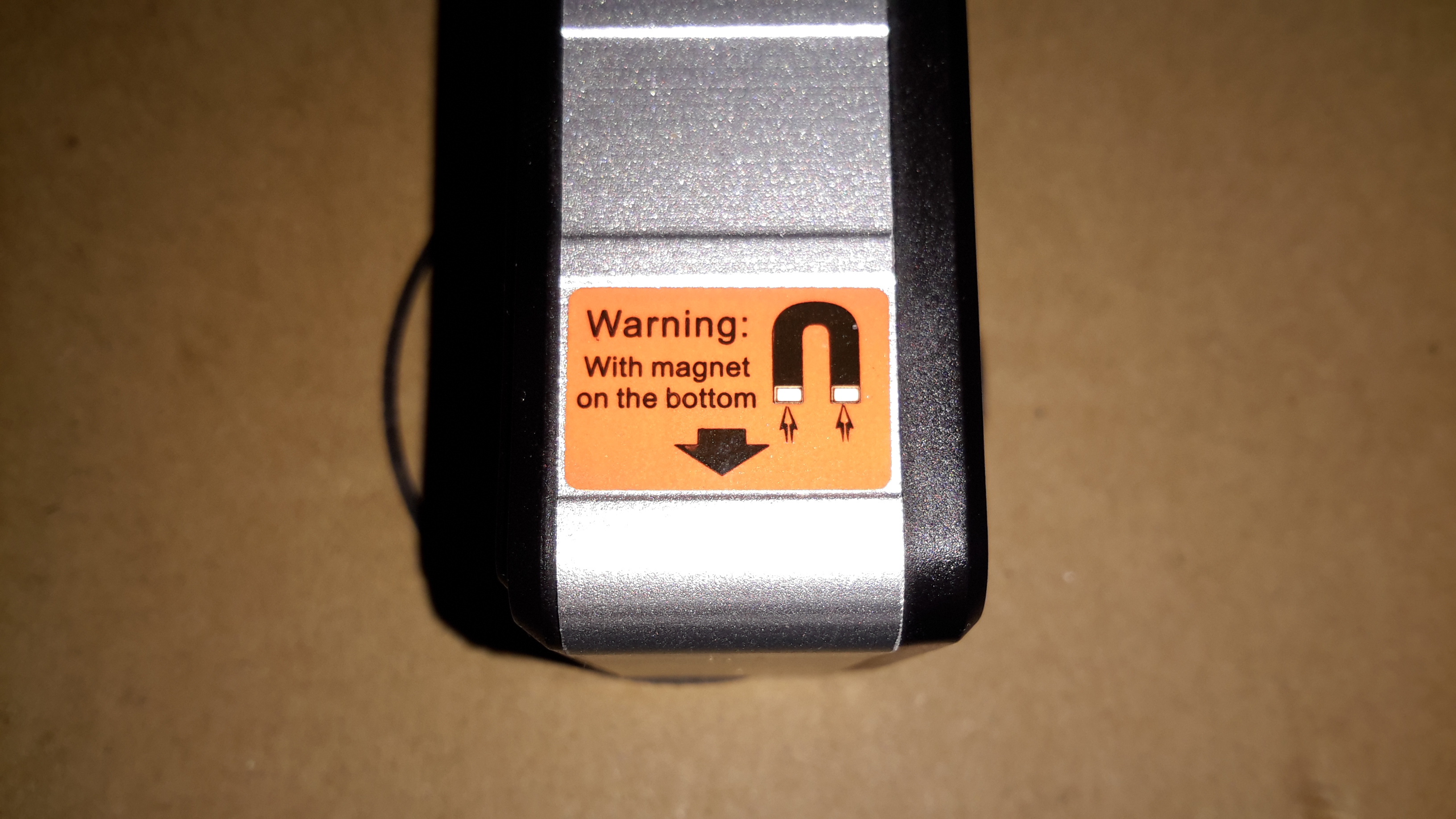
Magnets!
Magnets are provided in the base, so the tool can attach to any ferrous surface.
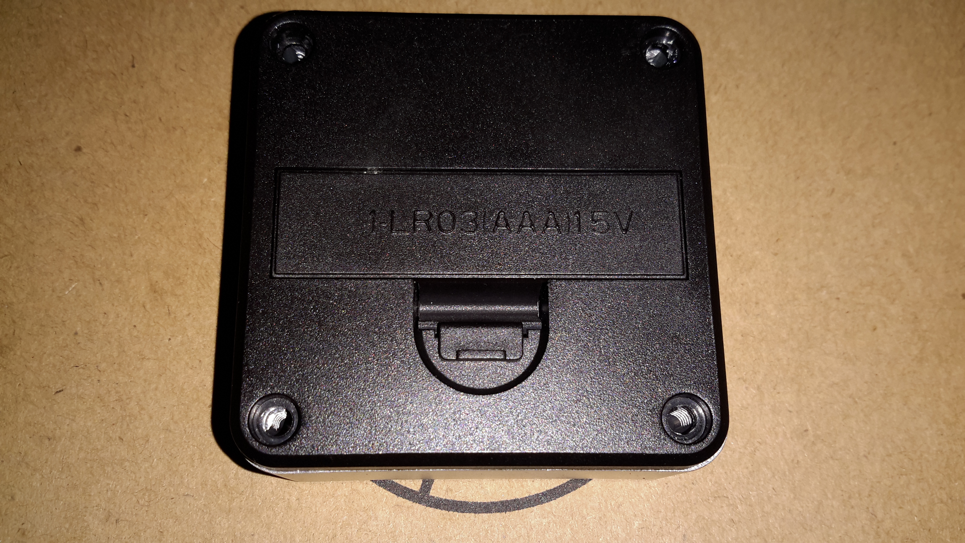
Battery Box
Power is provided by a single AAA cell.
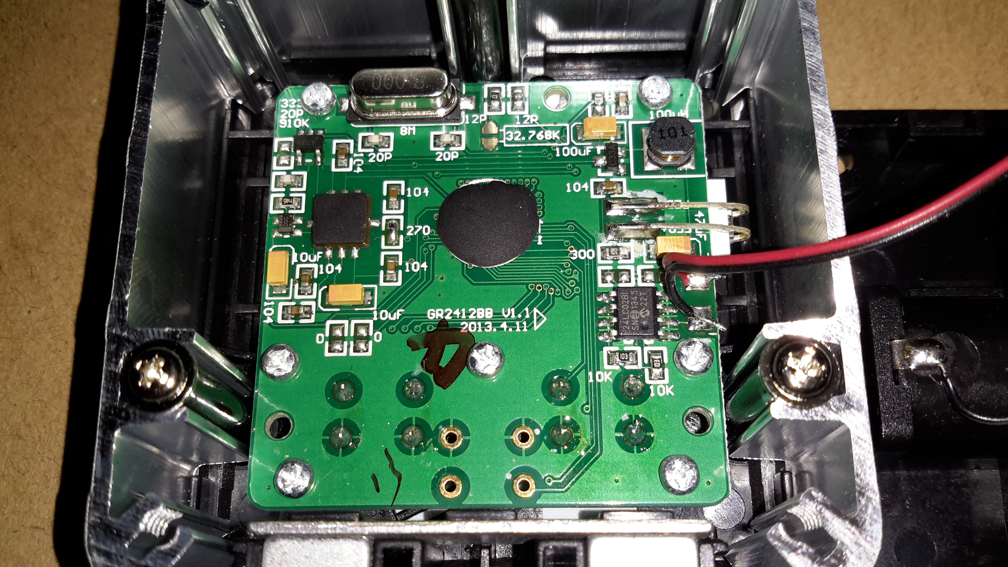
Main PCB
Removing the rear cover reveals the brains of the unit, and there’s not much to it at all. The main microcontroller is a CoB-type device, so no part numbers available from that one.
Sensing Element
The IC to the left of the main microcontroller is the sensing element. There’s no markings on this inclinometer IC so I’m not sure of the specs, but it will be a 3D-MEMS device of some sort.
Power Supply
The other side of the PCB has the power supply for the logic, and a serial EEPROM, probably storing calibration data.
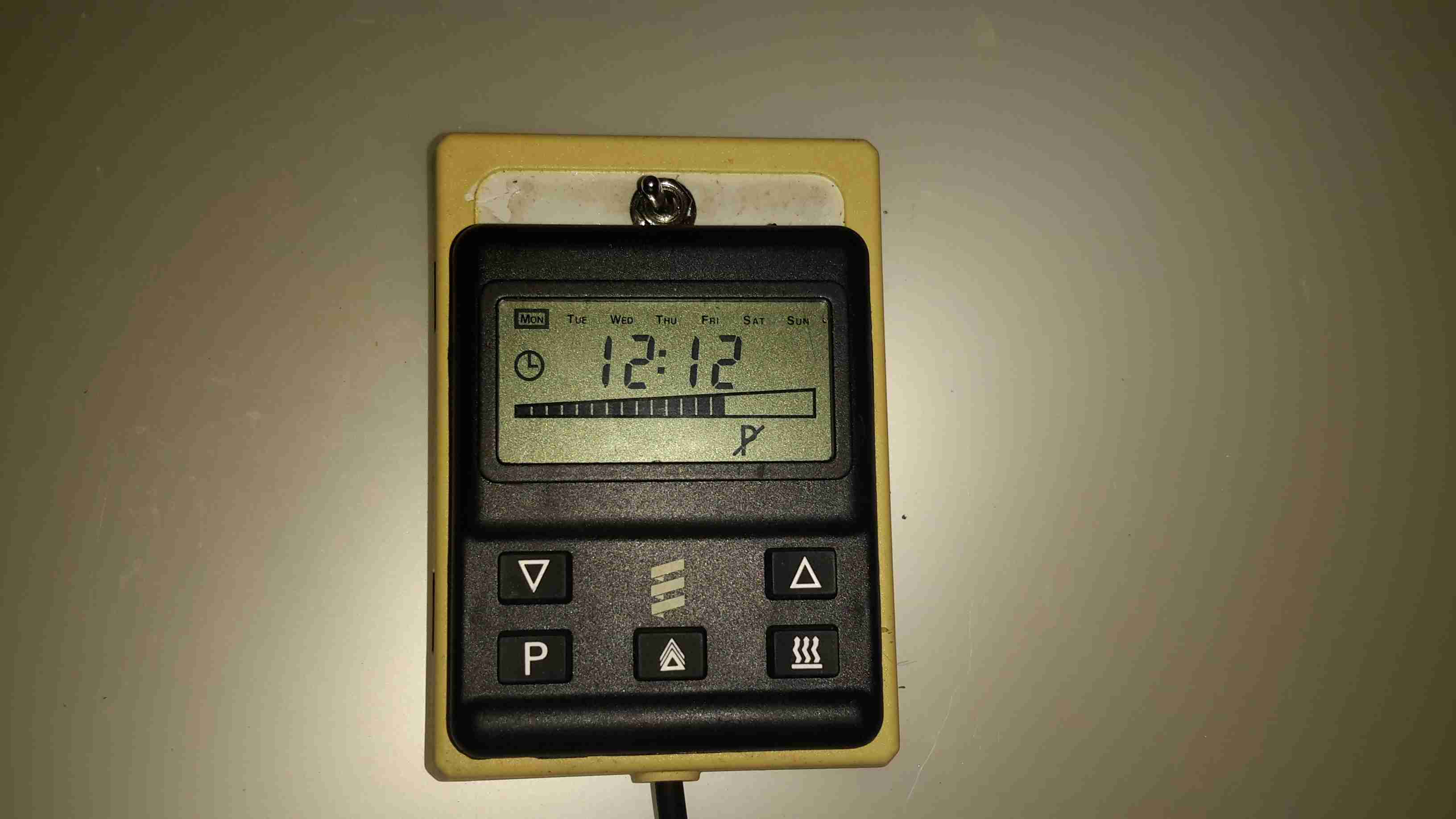
The Eberspacher heaters can be controlled with a single switch, but it’s more convenient to have some temperature control & the option of a timer. Above is an ex-BT 701 series controller, with built in 7-day programmer. Being an ex-BT van version though, it’ll only switch the heater on for 1 hour at a time.
To get around this slight niggle, I fitted a bypass toggle switch.
Remote Control
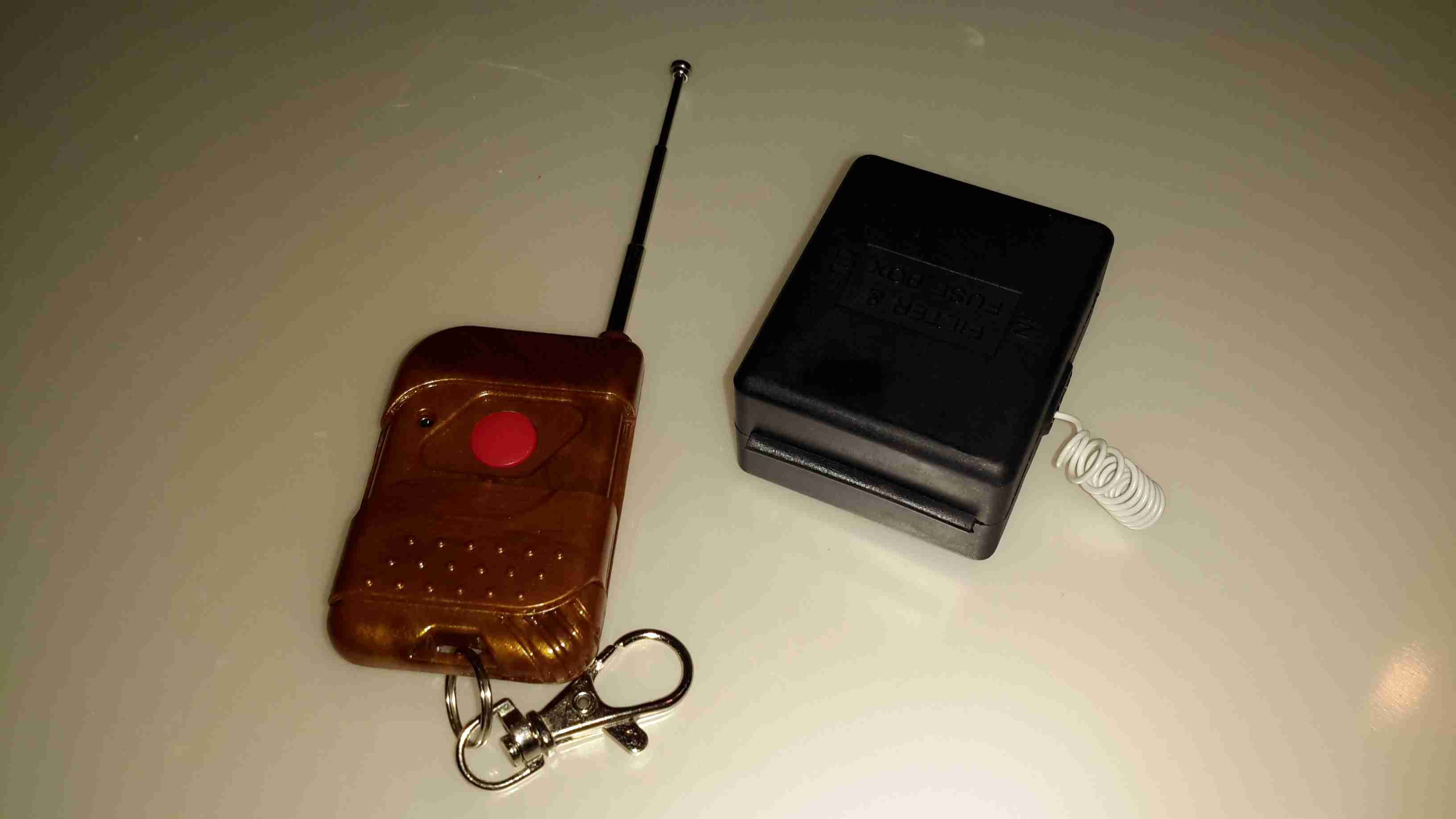
For a bit of extra convenience, I got an RF remote controlled relay module from eBay (£5).
This allows me to switch things on remotely, so I can return to a nice toasty tent while camping.
There is an official RF remote for Eberspacher heaters, but I’ve no doubt they’re hideously expensive.
RF Receiver
Here’s the receiver PCB, there’s an EEPROM & a microcontroller onboard for handling the codes the remotes send, but as the number has been scrubbed off the micro, no data there. This uses a standard RF receiver module.
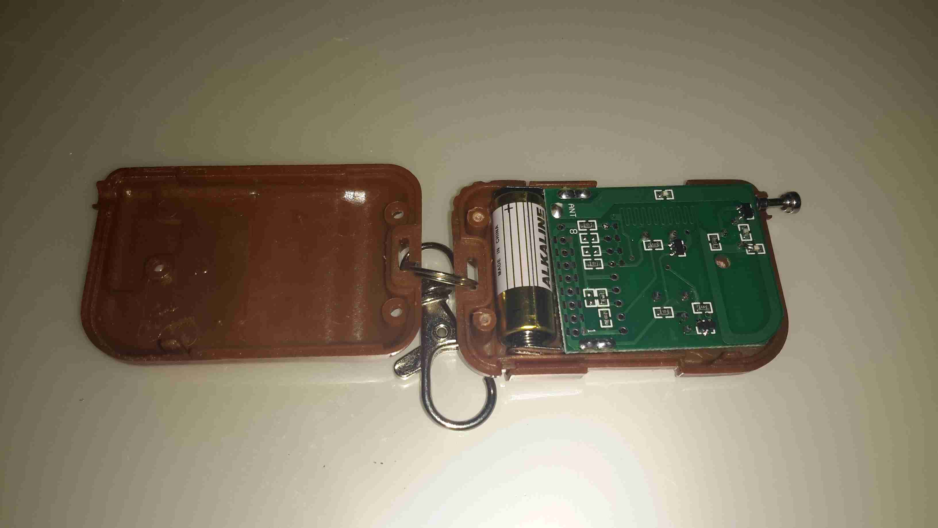
RF Remote
Here’s the remote itself, this uses a 12v battery instead of a 3v lithium cell. A little of a pain since these batteries can be a bit pricey.
As this RF system operates on 315MHz, it’s technically illegal in the UK, but I was unable to find a 433MHz version with the features required. Nevermind ;).
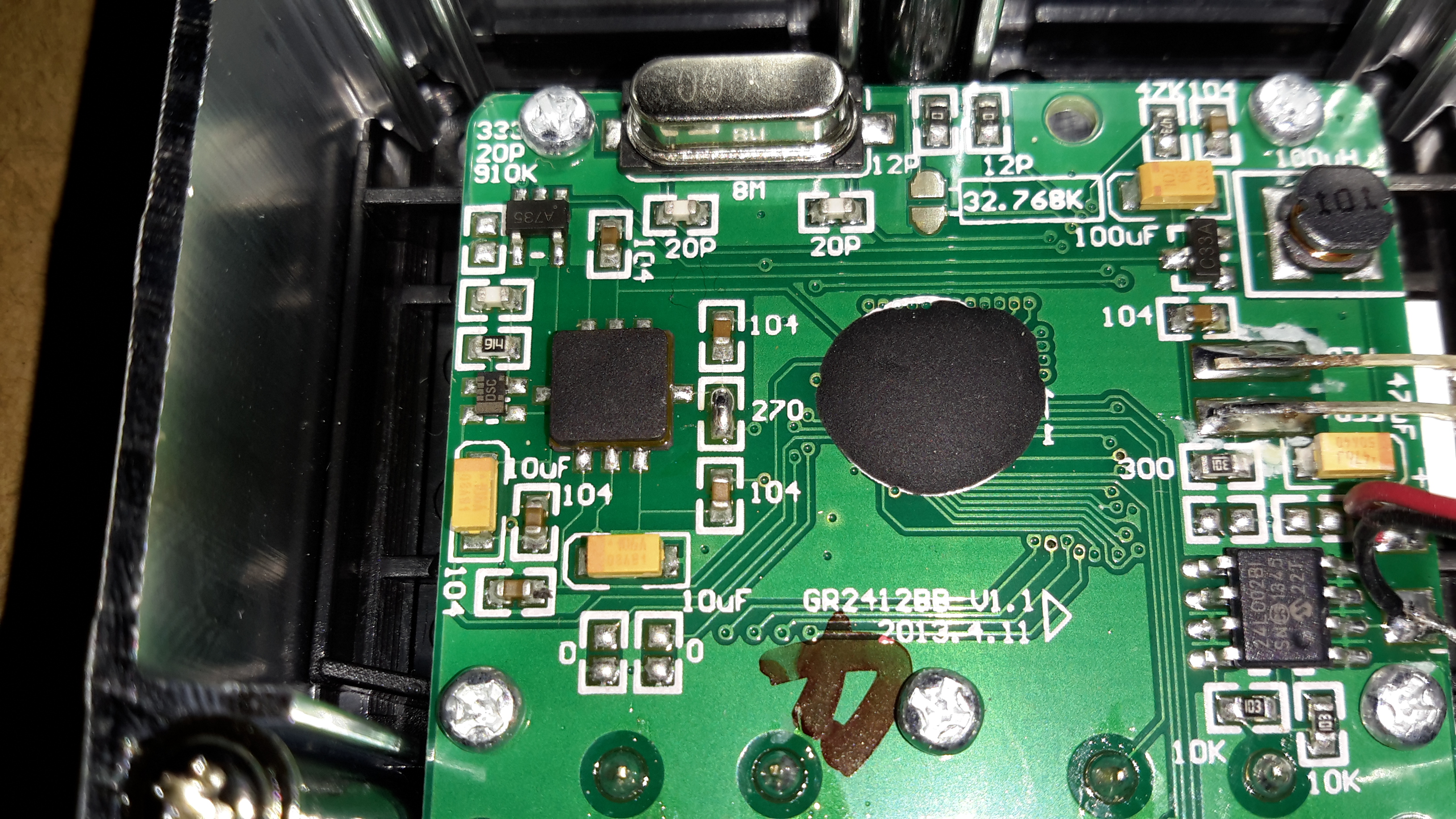
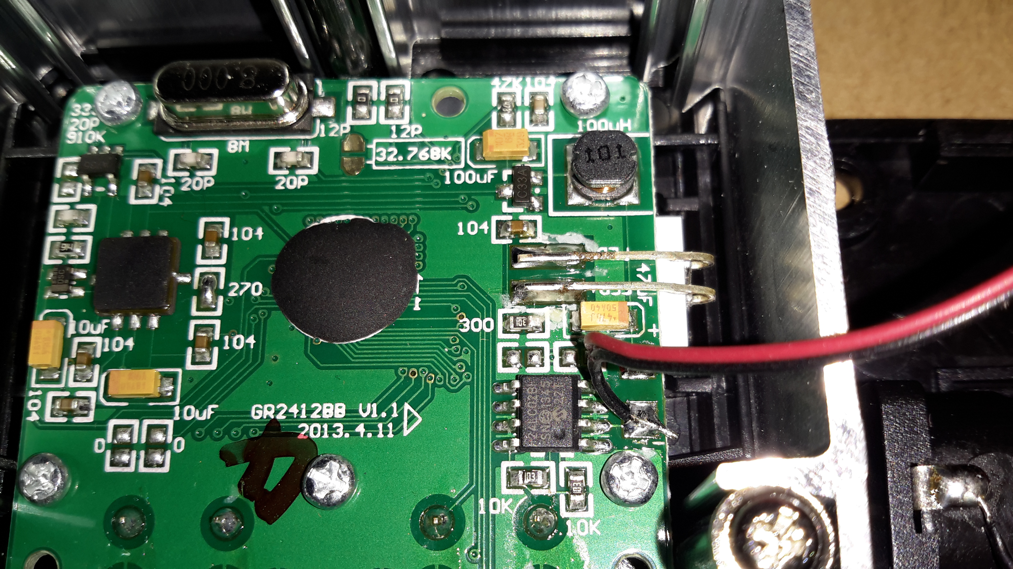
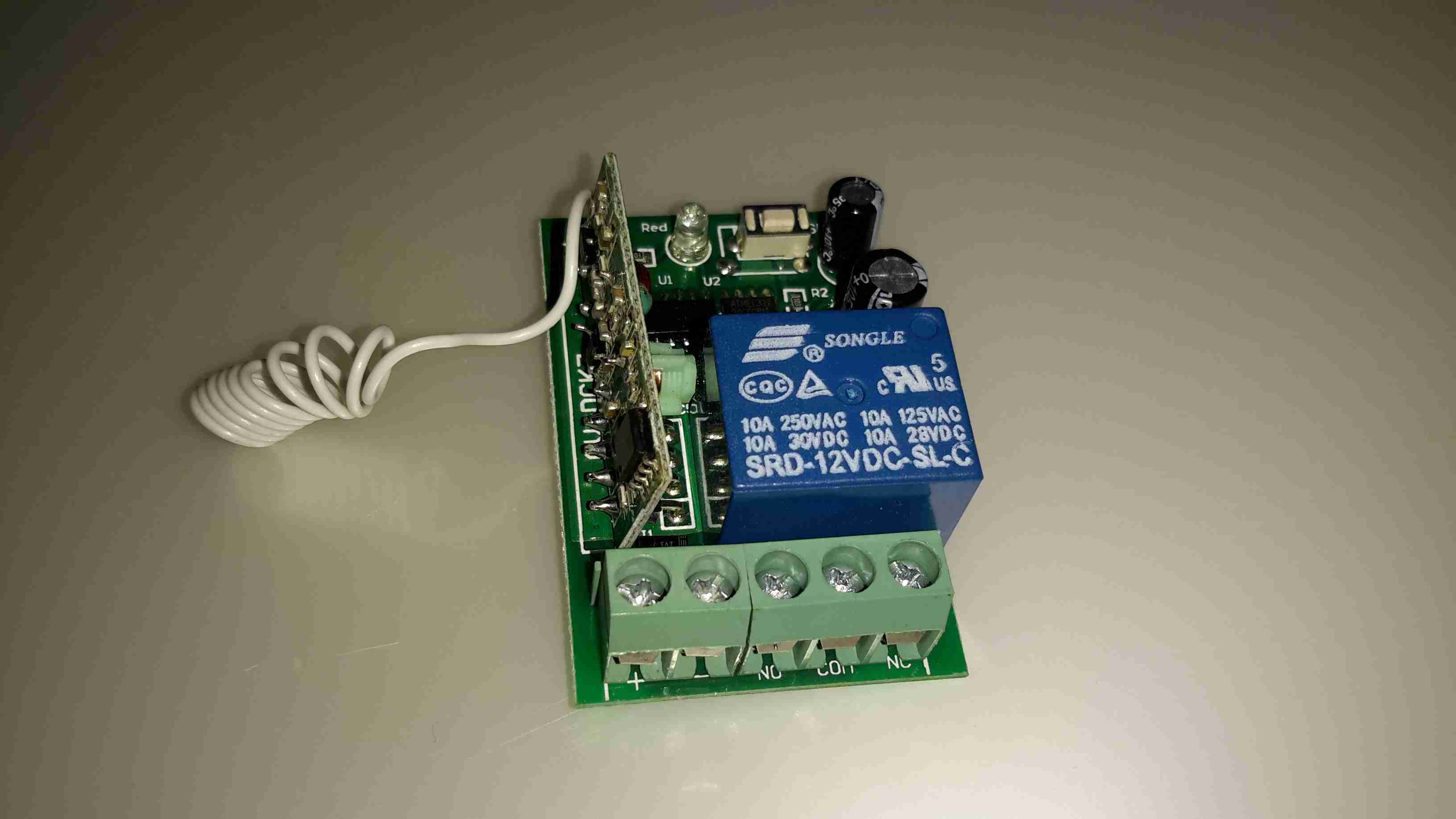
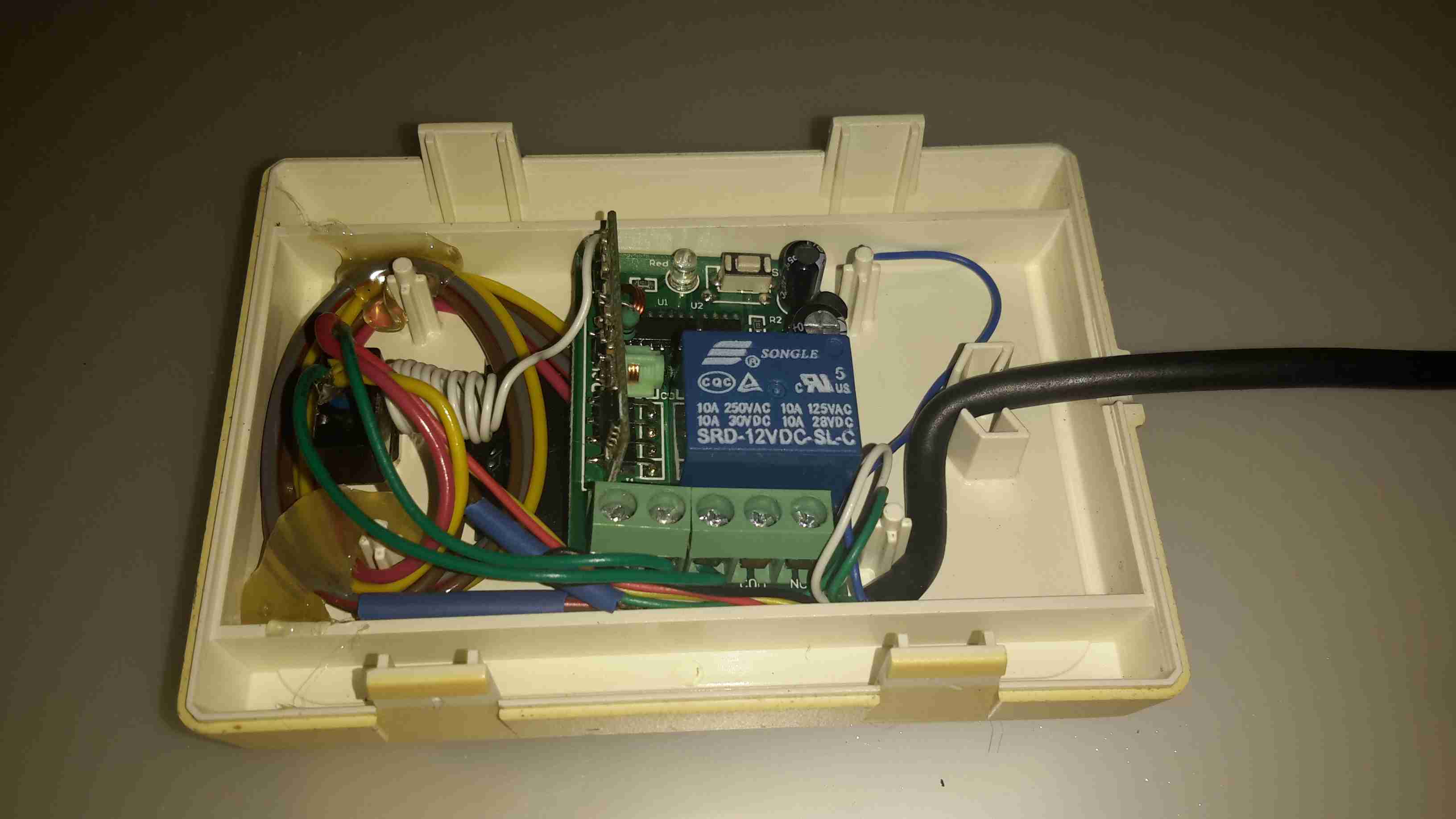
Controller Internals
Here’s the module installed in the controller casing. I have since run the antenna wire around the edge of the case to try & get the furthest range on receive. The relay contacts are just paralleled across the bypass switch, so when the relay energizes the heater fires up.
Luckily the thermostatic control portion of the 701 programmer is operational even when heating mode is not active.
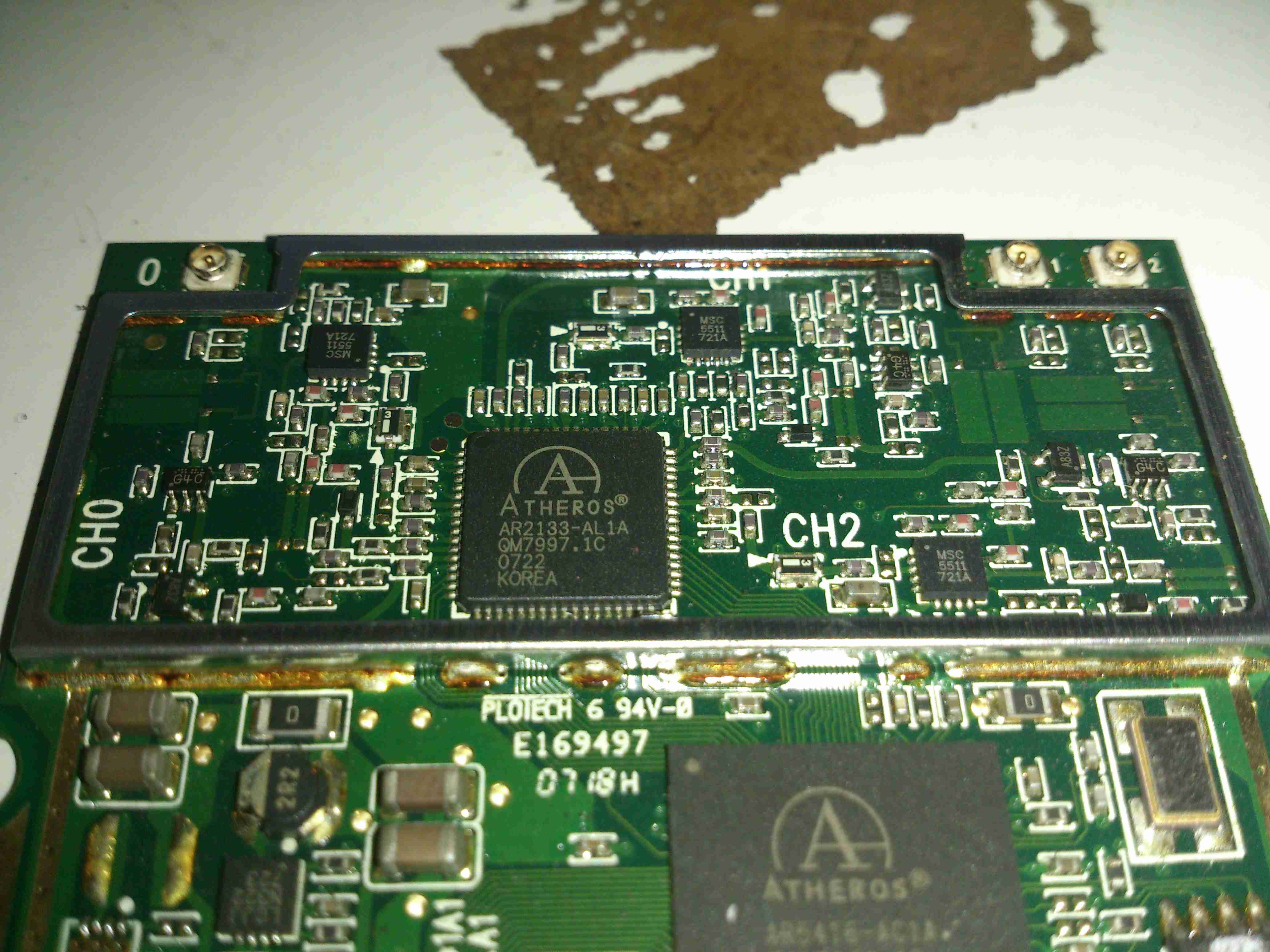
Here’s a quick look at one of the now surplus cards from my old networking system, a MiniPCI Wireless interface card.
Card Overview
This is an older generation card, one of the first with Wireless N support on 2.4GHz.
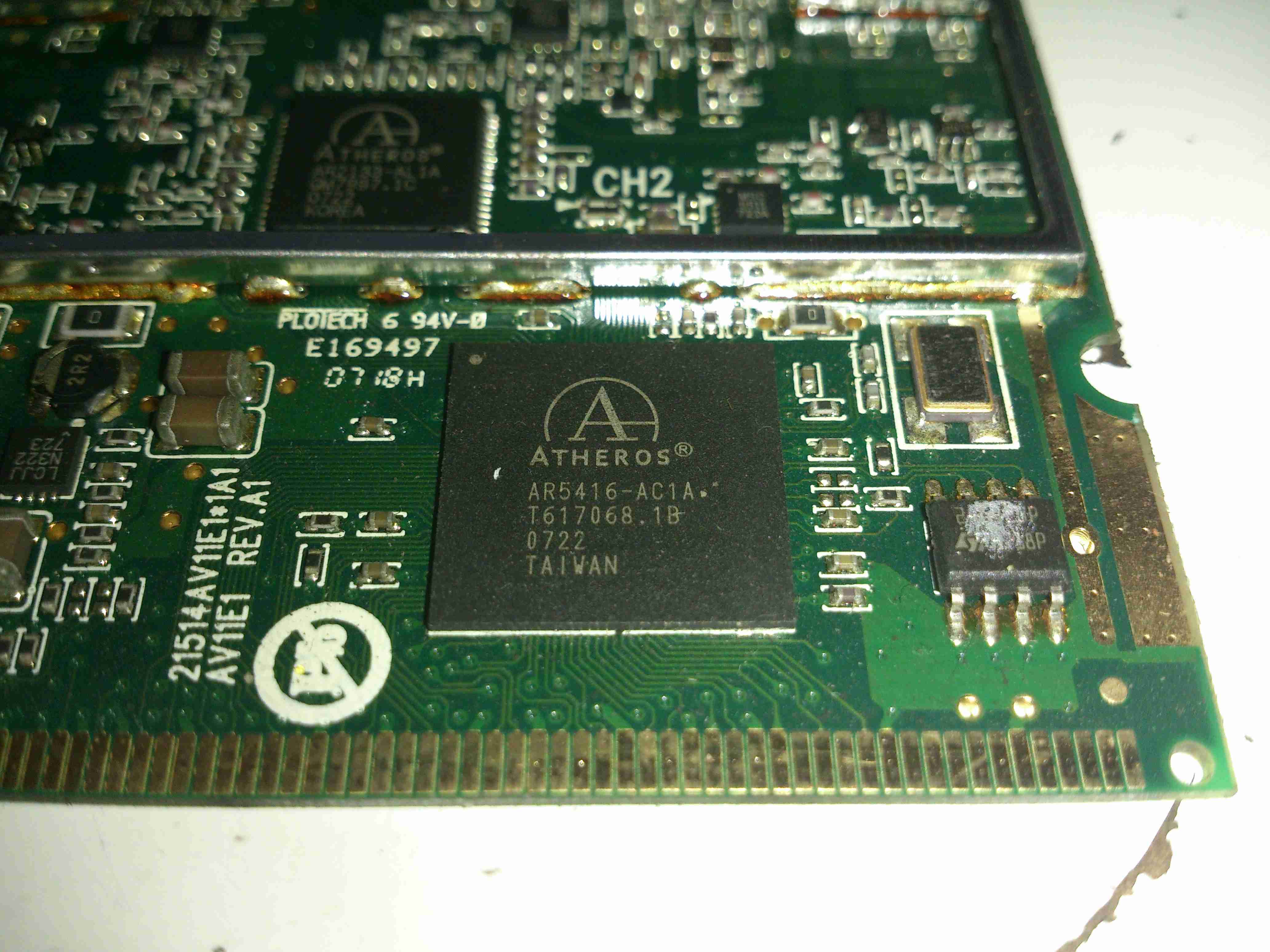
PCI Chipset
Network PHY & firmware EEPROM. Power supply stuff is over to the left.
RF Transceiver
Inside the shield is the RF Transceiver IC & it’s associated RF power amplifier ICs for each antenna. These power amplifiers are LX5511 types from Microsemi, with a maximum power output of +26dBm.
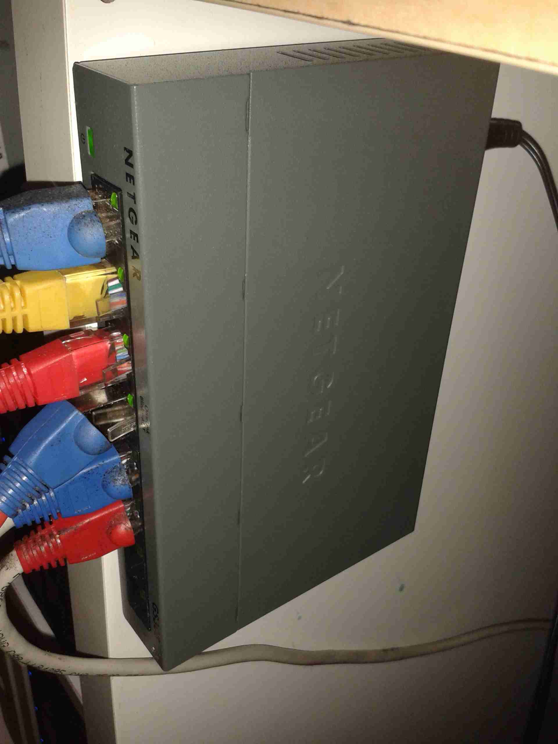
Here’s a new addition to the network, mainly to replace the ancient Cisco Catalyst 3500 XL 100MB switch I’ve been using for many years, until I can find a decently priced second hand commercial gigabit switch.
Operational
Here’s the switch with some network connections on test. So far it’s very stable & draws minimum power. I’ve not yet attempted to run my core links (NAS) through yet, as I’ve not yet seen a consumer grade switch that can stand up to constant full load without crashing.
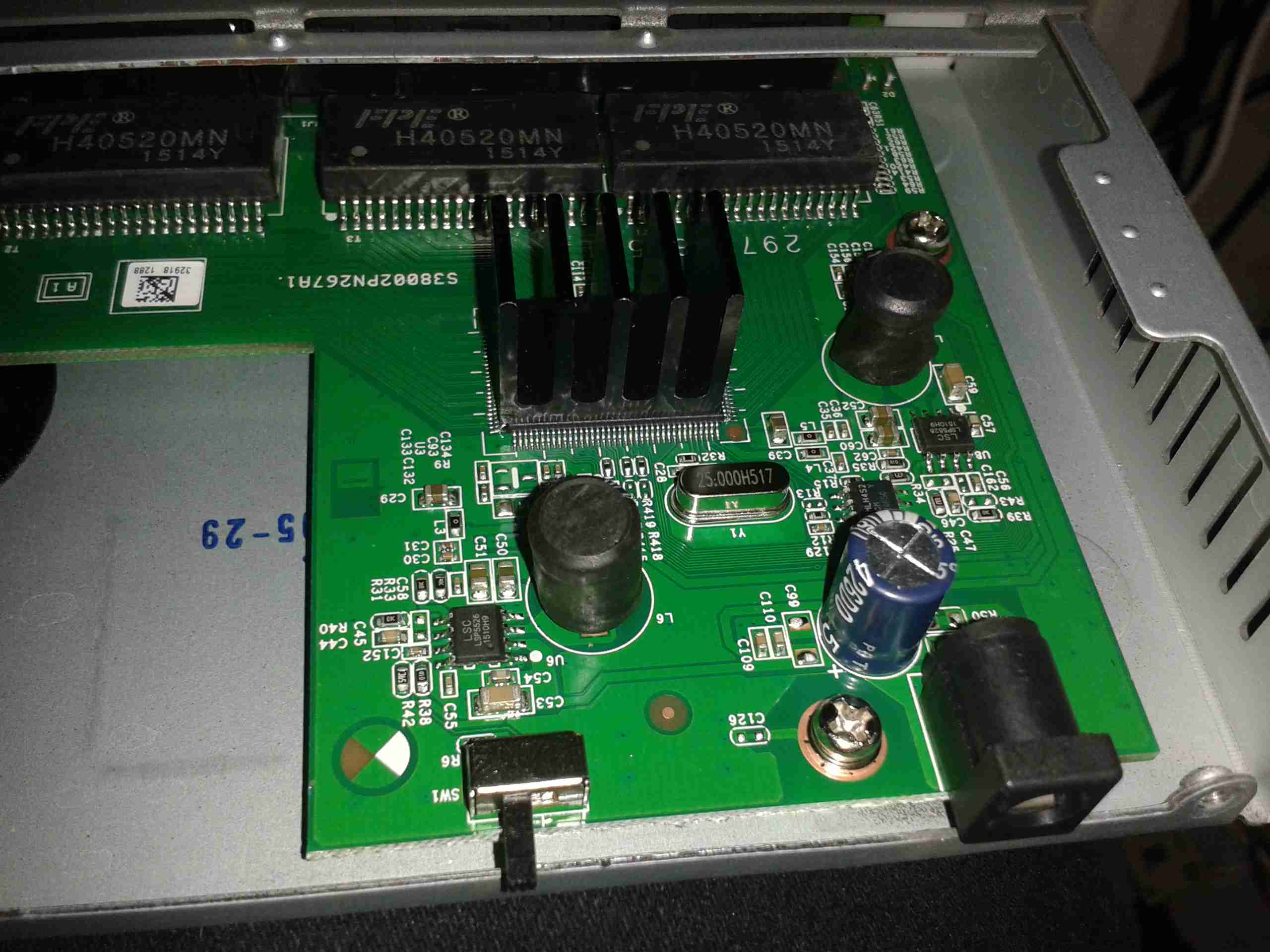
Internals
Here’s the switch with it’s lid popped. The magnetics can be seen at the back, next to the RJ-45 ports, the large IC in the centre is the main switching IC, with a heatsink bonded to the top. Very minimal design, with only a couple of switching regulators for power supply & not much else.
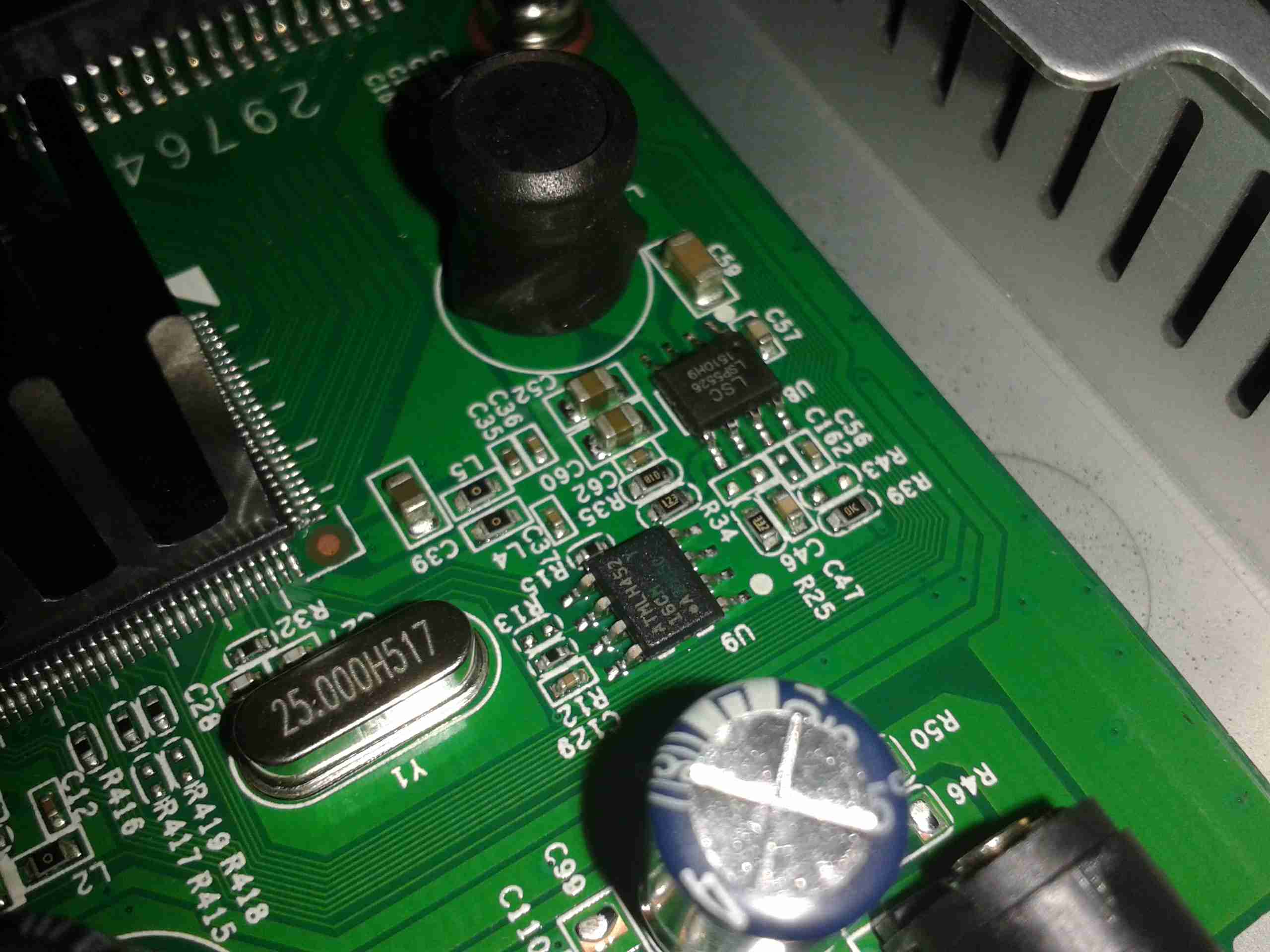
Power & EEPROM
Here’s a closeup of some of the support components. There’s a 25MHz crystal providing a clock signal for the switch IC, just to the right of that is an EEPROM. I imagine this is storing the switch configuration & MAC address. Further right is one of the switching DC-DC converter ICs for power.
As a quick test, here’s 500GB of data being shifted through the switch, at quite an impressive rate. I’m clearly maxing out the bandwidth of the link here. Soon I will upgrade to a 10G Ethernet link between the NAS & main PC to get some more performance.
I recently posted about a small analog SWR/Power meter I got from eBay, and figured it needed some improvement.
After some web searching I located a project by ON7EQ, an Arduino sketch to read SWR & RF power from any SWR bridge.
The Arduino code is on the original author’s page above, his copyright restrictions forbid me to reproduce it here.
I have also noticed a small glitch in the code when it is flashed to a blank arduino: The display will show scrambled characters as if it has crashed. However pushing the buttons a few times & rebooting the Arduino seems to fix this. I think it’s related to the EEPROM being blank on a new Arduino board.
I have run a board up in Eagle for testing, shown below is the layout:
SWR Meter SCH
The Schematic is the same as is given on ON7EQ’s site. Update: ON7EQ has kindly let me know I’ve mixed up R6 & R7, so make sure they’re switched round when the board is built ;). Fitting the resistors the wrong way around may damage the µC with overvoltage.
SWR Meter PCB
Here’s the PCB layout. I’ve kept it as simple as possible with only a single link on the top side of the board.
PCB Top
Here’s the freshly completed PCB ready to rock. Arduino Pro mini sits in the center doing all the work.
The link over to A5 on the arduino can be seen here, this allows the code to detect the supply voltage, useful for battery operation.
On the right hand edge of the PCB are the pair of SMA connectors to interface with the SWR bridge. Some RF filtering is provided on the inputs.
PCB Bottom
Trackside view of the PCB. This was etched using my tweaked toner transfer method.
LCD Fitted
Here the board has it’s 16×2 LCD module.
Online
Board powered & working. Here it’s set to the 70cm band. The pair of buttons on the bottom edge of the board change bands & operating modes.
As usual, the Eagle layout files are available below, along with the libraries I use.
[download id=”5585″]
[download id=”5573″]
More to come on this when some components arrive to interface this board with the SWR bridge in the eBay meter.
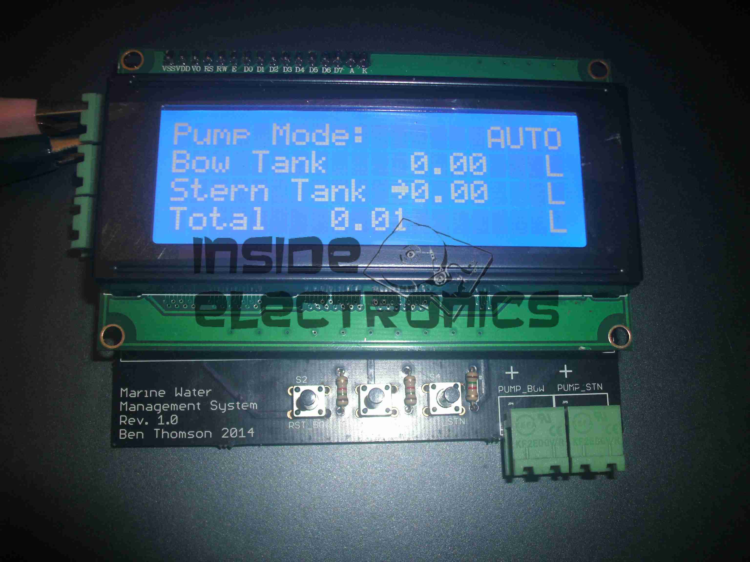
Having two separate water tanks on nb Tanya Louise, with individual pumps, meant that monitoring water levels in tanks & keeping them topped up without emptying & having to reprime pumps every time was a hassle.
To this end I have designed & built this device, to monitor water usage from the individual tanks & automatically switch over when the tank in use nears empty, alerting the user in the process so the empty tanks can be refilled.
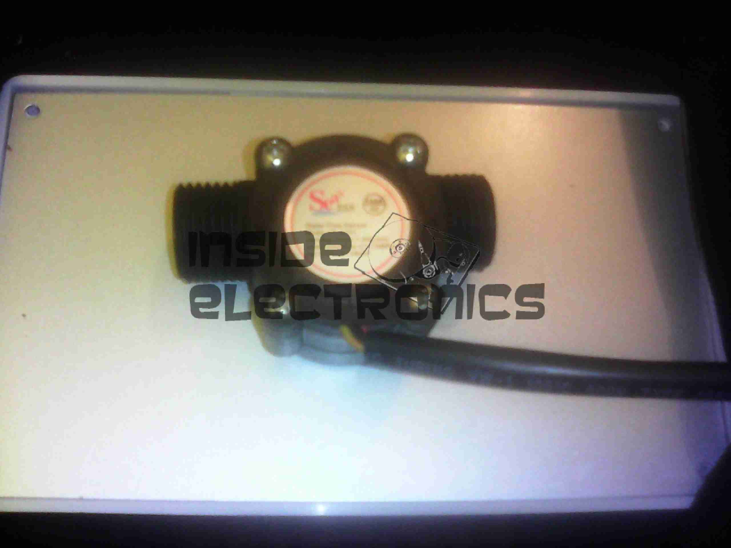
Based around an ATMega328, the unit reads a pair of sensors, fitted into the suction line of each pump from the tanks. The calculated flow is displayed on the 20×4 LCD, & logged to EEPROM, in case of power failure.
Water Flow Sensor
When the tank in use reaches a preset number of litres flowed, (currently hardcoded, but user input will be implemented soon), the pump is disabled & the other tank pump is enabled. This is also indicated on the display by the arrow to the left of the flow register. Tank switching is alerted by the built in beeper.
It is also possible to manually select a tank to use, & disable automatic operation.
Resetting the individual tank registers is done by a pair of pushbuttons, the total flow register is non-resettable, unless a hard reset is performed to clear the onboard EEPROM.
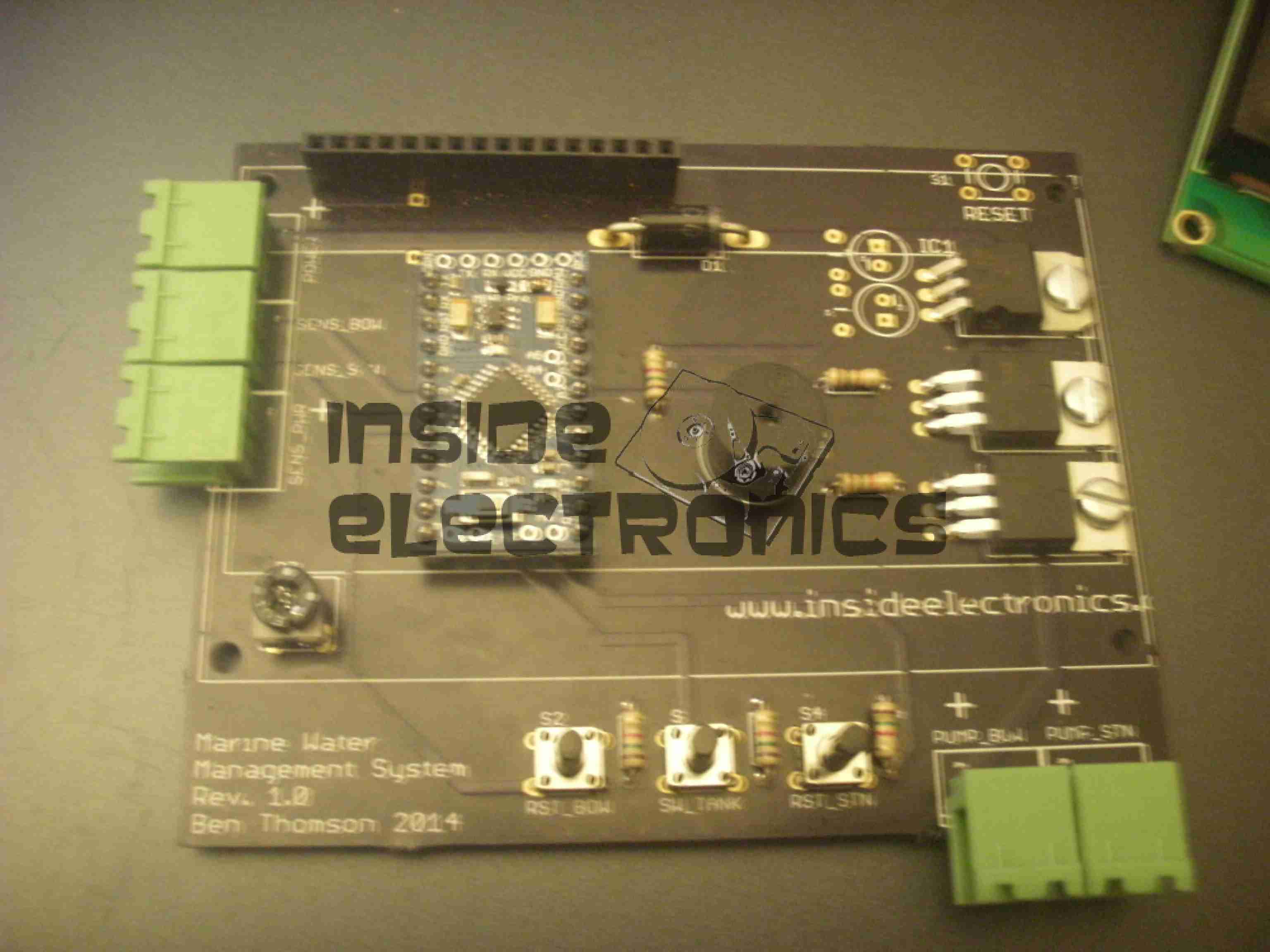
Main PCB
View of the main PCB is above, with the central Arduino Pro Mini module hosting the backend code. 12-24v power input, sensor input & 5v sensor power output is on the connectors on the left, while the pair of pump outputs is on the bottom right, switched by a pair of IRFZ44N logic-level MOSFETS. Onboard 5v power for the logic is provided by the LM7805 top right.
Code & PCB design is still under development, but I will most likely post the design files & Arduino sketch once some more polishing has been done.
This is an old cordless landline phone, with dead handset batteries.
Handset Radio Board
Here’s the handset with the back removed. Shown is the radio TX/RX board, underneath is the keyboard PCB with the speaker & mic. All the FM radio tuning coils are visible & a LT450GW electromechanical filter.
Handset Radio Board Bottom
Radio PCB removed from the housing showing the main CPU controlling the unit, a Motorola MC13109FB.
Keypad Board
The keypad PCB, with also holds the microphone & speaker.
Handset Keypad Board Bottom
Bottom of the keypad board, which holds a LSC526534DW 8-Bit µC & a AT93C46R serial EEPROM for phone number storage.
Base Main Board
Here’s the base unit with it’s top cover removed. Black square object on far right of image is the microphone for intercom use, power supply section is top left, phone interface bottom left, FM radio is centre. Battery snap for power backup is bottom right.
Power Supply Section
PSU section of the board on the left here, 9v AC input socket at the bottom, with bridge rectifier diodes & main filter capacitor above. Two green transformers on the right are for audio impedance matching. Another LT450GW filter is visible at the top, part of the base unit FM transceiver.
ICs
Another 8-bit µC, this time a LSC526535P, paired with another AT93C46 EEPROM. Blue blob is 3.58MHz crystal resonator for the MCU clock. The SEC IC is a KS58015 4-bit binary to DTMF dialer IC. This is controlled by the µC.
Base Main Board Bottom
Underside of the base unit Main PCB, showing the matching MC13109FB IC for the radio functions.
This is an old USB 1.1 hub that was recently retired from service on some servers. Top of the unit visible here.
Bottom Label
Bottom label shows that this is a model F5U021 hub, a rather old unit.
PCB Front
PCB is here removed from the casing, Indicator LEDs along the bottom edge of the board, power supply is on the left. Connectors on the top edge are external power, USB host, & the 4 USB outputs. Yellow devices are polyswitch fuses for the 500mA at 5v each port must supply.
USB Hub IC
This is the USB Hub Controller IC, which is a Texas Instruments TUSB2046B device. Power filter capacitors next to the USB ports are visible here also, along with 2 of the polyswitches.
Power Supply
The power supply section of the unit, which supplies regulated 5v to the ports, while supplying regulated 3.3v to the hub controller IC. Large TO-220 IC is the 5v regulator. Smaller IC just under the power selector switch is the 3.3v regulator for the hub IC. The switch selects between Host powered or external power for the hub.
Here is a cheap chinese made flash drive given out for free by Westlaw UK. Capacity 512MB
PCB
Here is the PCB removed from the casing, USB connector on the left, followed by the clock crystal for the flash controller, a CBM2092, which is a Chipsbank part. 512MB flash memory IC, unknown maker. Access LED on far right of the board.
This is the Current Cost CC128 Real Time Power Meter. Shown here is the display unit, British Gas issued these free to some customers.
This unit measures current power draw in Watts, cost of power currently being used (requires unit price to be set), overall kWh usage over the past 1, 7 or 30 days & power trends during the day, night & evening. Also displays current time & current room temperature.
Display PCB
Here the front panel of the display has been un-clipped. At the bottom are the RJ-45 serial port & power connections.
This unit uses a PIC micro-controller as it’s CPU (PIC18F85J90) Just above & left of the CPU is the 433MHz SPD radio receiver module. The chips on the right of the CPU are a 25LC128 SPI serial EEPROM for data storage & a 74HC4060 14 stage binary counter, to which is connected the 32kHz clock crystal. The red wire around the top of the display is the antenna for the radio receiver.
For more info on the CC128 in general, the serial port & software for computer data logging, see this link
See this link for Current Cost’s list of software
Processor & Radio
Closeup of the ICs on the mainboard.
Transmitter Unit
Here we have the transmitter unit, with Current Transformer (CT). The red clamp fits around one of the electric meter tails & read the current going to the various circuits. This unit is powered by 2x D cells, rated at a life of 7 years.
Transmitter PCB
The PCB inside the transmitter. Again very minimal design, unknown controller IC, 433MHz radio transmitter on right hand side with wire antenna. Two barrel connectors on left hand side of board allow connection of up to two more CT clamps for measurement of 3-phase power. Centre of board is unmarked header. (ICSP?)
Current Transformer
CT unit. Inside is a coil of wire & an iron core which surrounds the cable to be measured.
PIC18F85J90
Tip Jar
If you’ve found my content useful, please consider leaving a donation by clicking the Tip Jar below!
All collected funds go towards new content & the costs of keeping the server online.