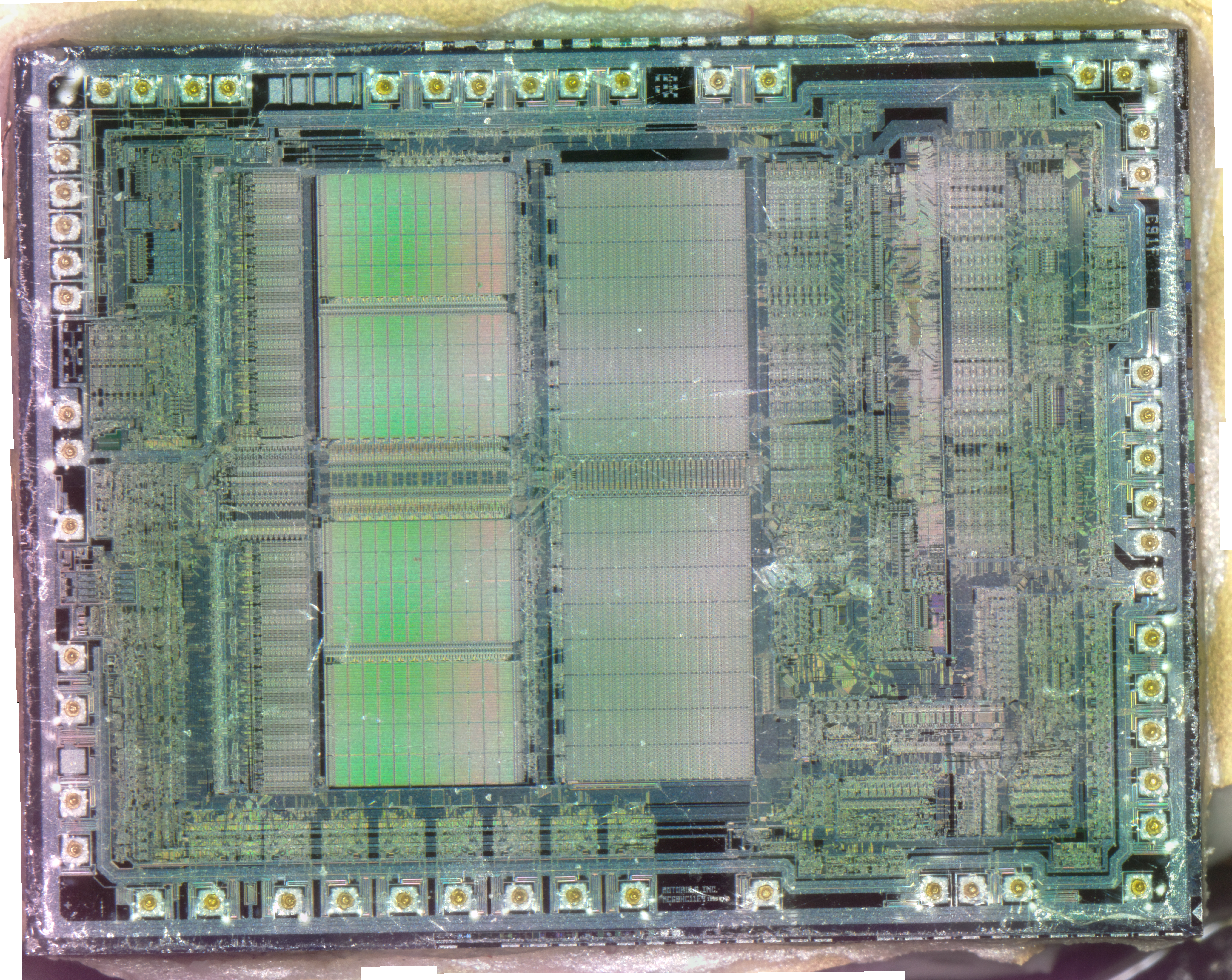
This particular IC came out of a very old VHF band radio, from the early 90’s. The die was encased in a custom ceramic package, like every other IC in the radio, with a custom part number. I managed to identify it from the markings on the silicon.
Motorola MC68HC11L6
This was a pretty powerful MCU for it’s time, with 16K of onboard ROM, 512 bytes of both RAM & EEPROM, a 16-bit timer, 8-bit ADC, SPI & a MC68HC11 CPU core.
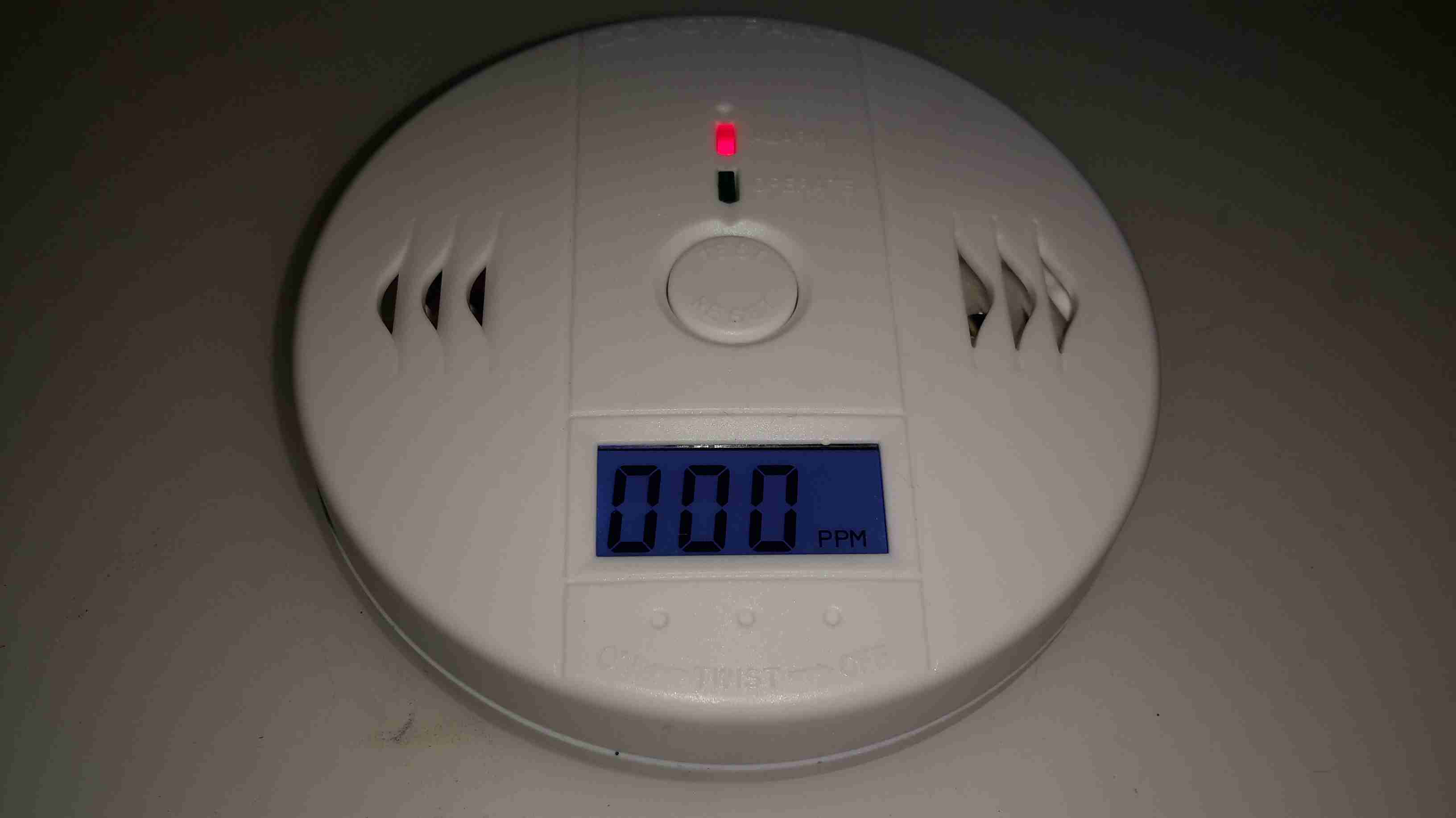
I was looking around eBay for decent deals on a branded CO alarm, and came across these for next to no money, so I thought I’d grab one just to see how bad they could be.
Alarm Opened
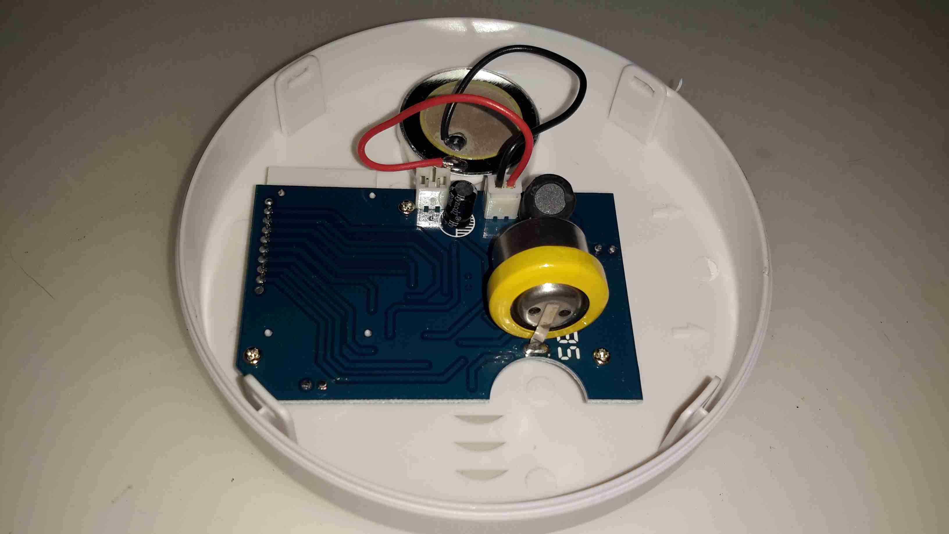
Popping the casing open shows the very small circuit board inside, with the CO sensor cell on the right. I can’t find any manufacturer information on this cell, nor can I find a photo of anything similar on the intertubes, so no specifications there. The other parts are pretty standard, a Piezo sounder & it’s associated step-up transformer to increase the loudness.
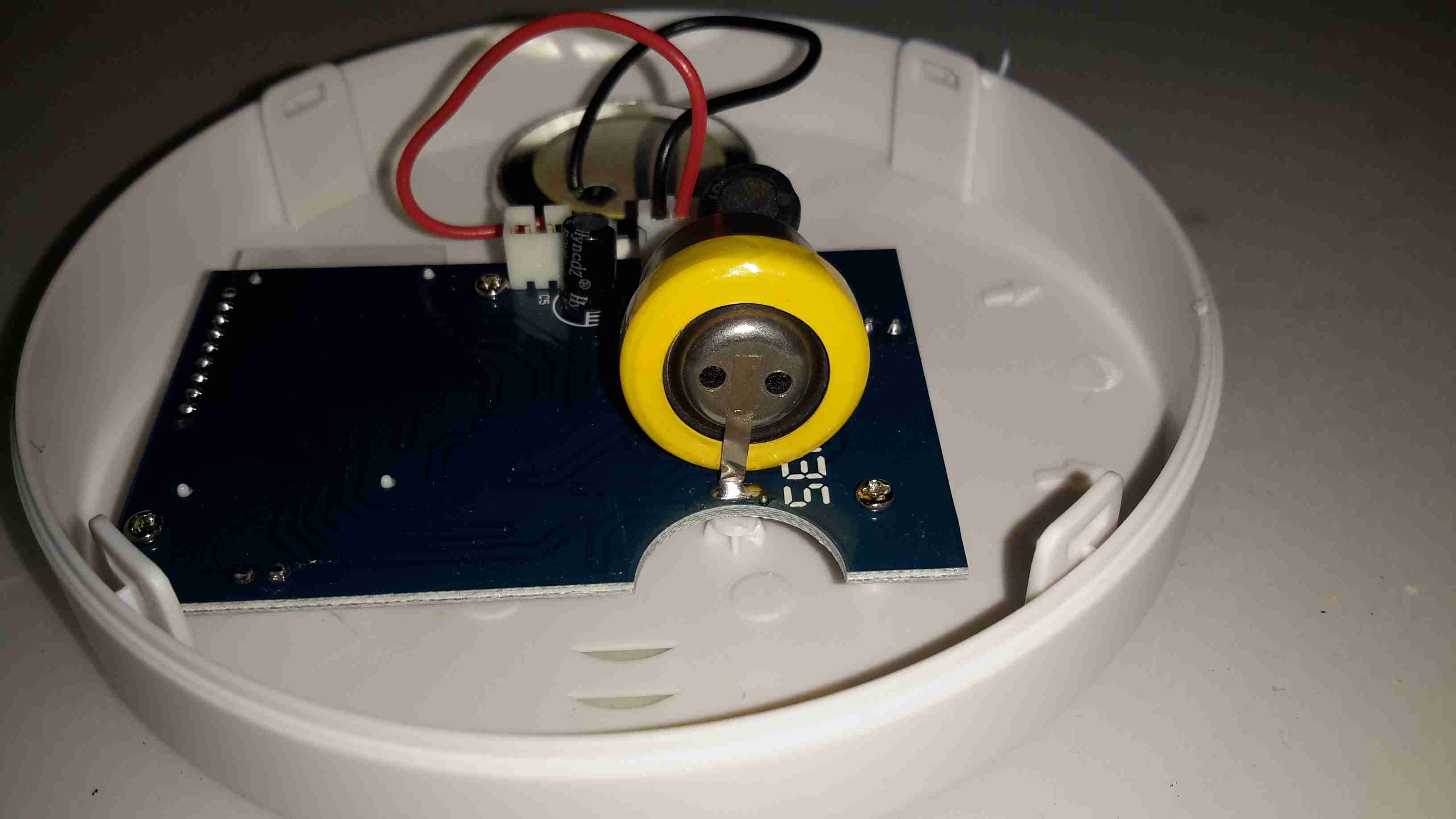
Sensor Closeup
The sensor cell has the usual opening in the end to allow entry of gas.
Main PCB
The other side of the board doesn’t reveal much, just an LCD, a couple of LEDs, a pair of transistors, Op-Amp for the sensor & a main microcontroller.
MCU
The microcontroller isn’t marked unfortunately. It’s not had the number scrubbed off, it’s just never been laser marked with a part number. Above the micro is a SOT-23 LM321 low-power Op-Amp which does the signal conditioning for the CO sensor.
I tried to make this alarm trigger with the exhaust from the Eberspacher heater, which on a well-made branded alarm registered a reading of 154ppm after a few minutes. In the case of this alarm though, I couldn’t make it trigger at all, no matter how long I exposed it to hydrocarbon exhaust gases. I won’t be trusting this one then!
Nothing quite like a piece of safety equipment that doesn’t work correctly from new!
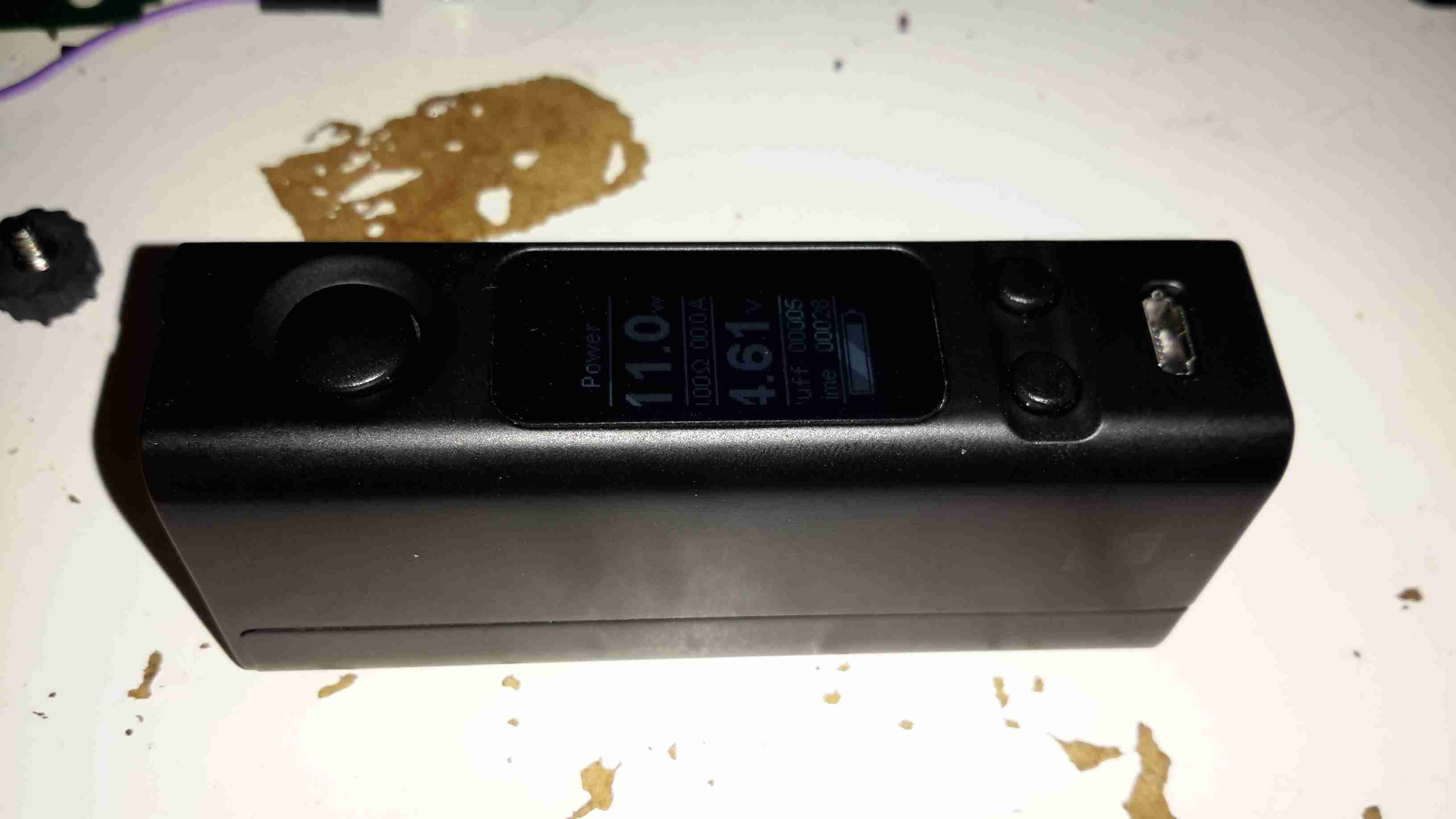
I’ve been a vaper now for many years, after giving up the evil weed that is tobacco. Here’s my latest acquisition in the vaping world, the JoyeTech eVIC 60W. This one is branded by Totally Wicked as the Forza VT60.
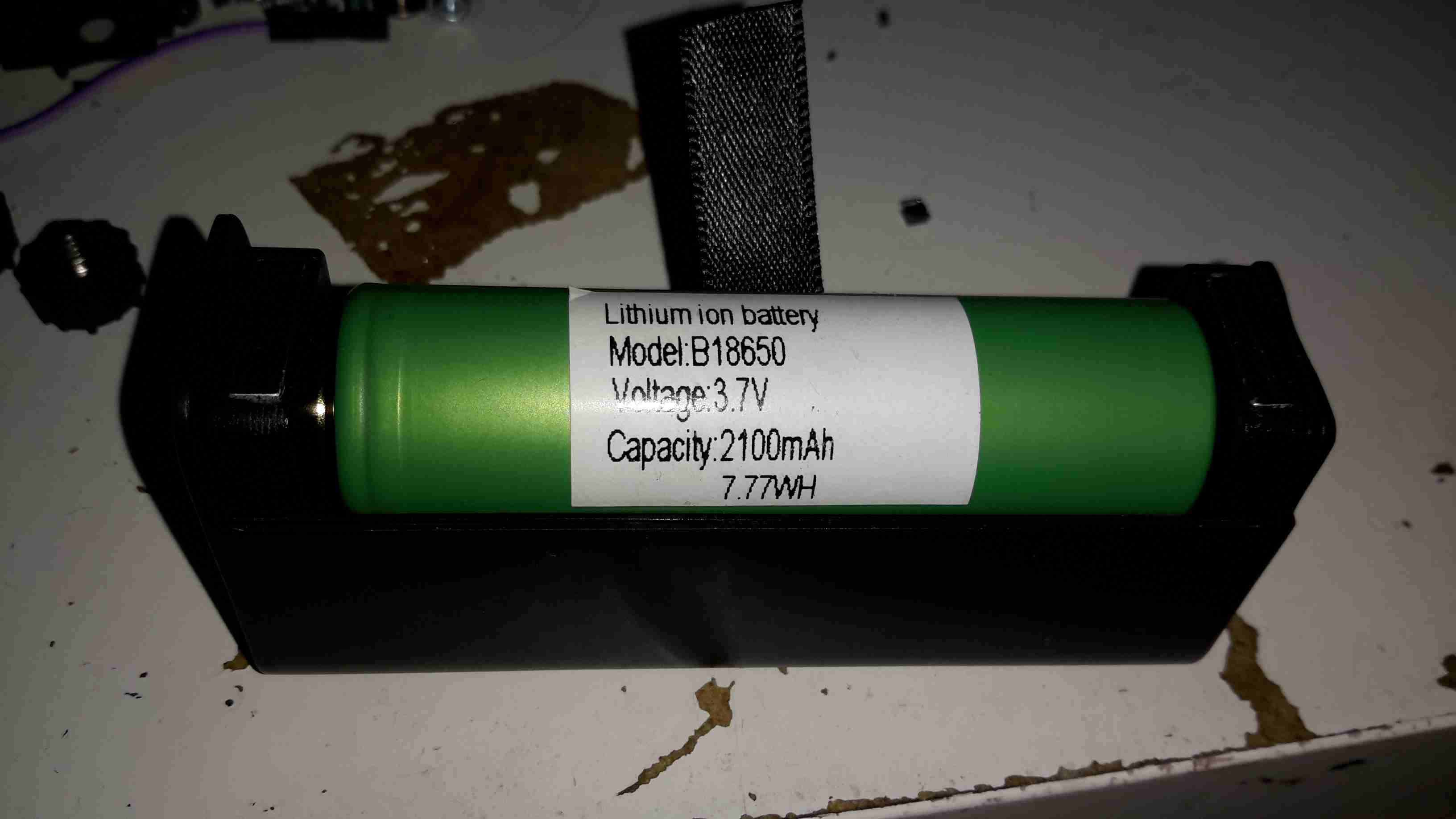
18650 Cell
Powered by a single 18650 Li-Ion cell, this one is a Sony VTC4 series, 2100mAh.
Under the battery a pair of screws hold the electronics in the main cast alloy casing.
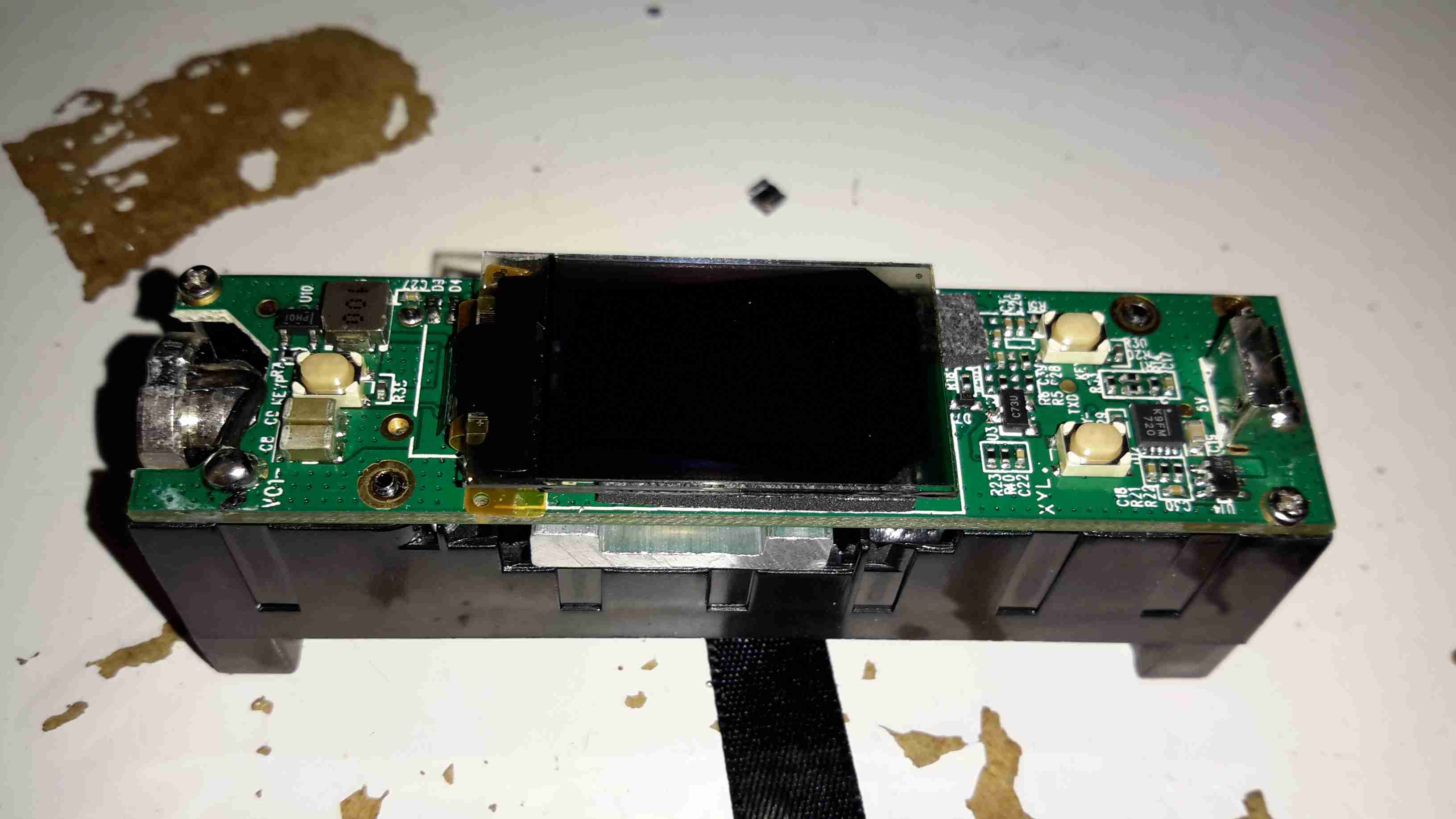
OLED Display
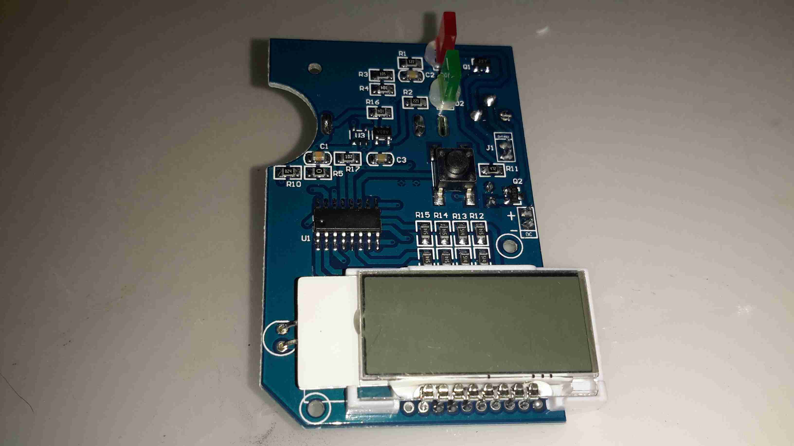
After removing the screws, the entire internal assembly comes out of the case, here’s the top of the PCB with the large OLED display in the centre.
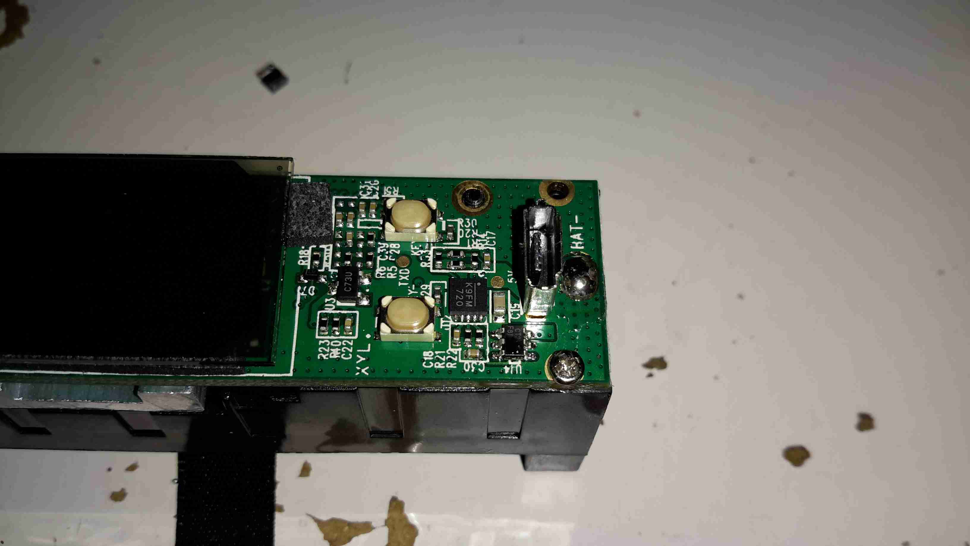
USB Jack
On the right side of the board is the USB jack for charging & firmware updates. The adjustment buttons are also at this end.
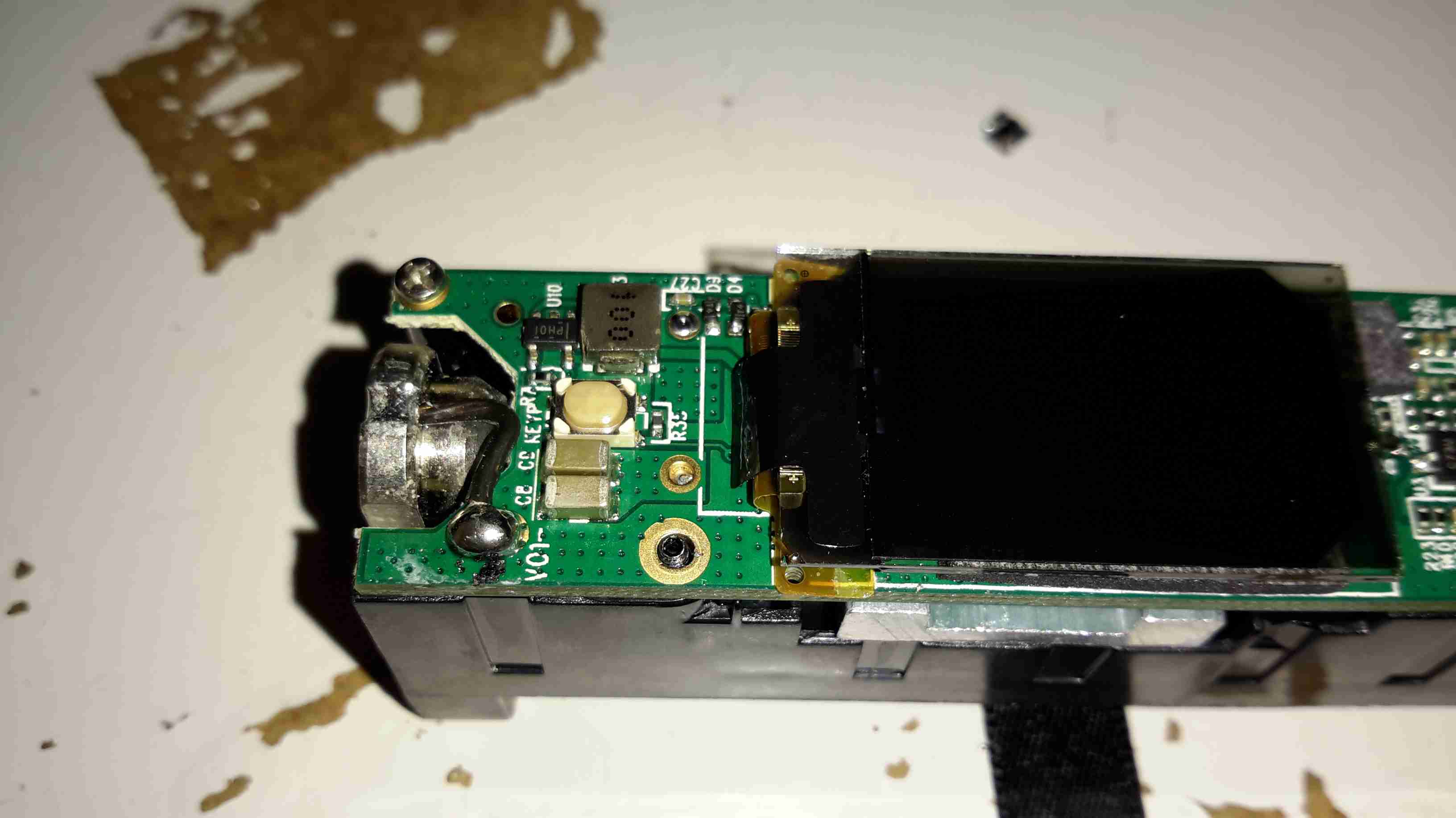
Output
On the left side of the board is the main output connector & the fire button. Unlike many eCigs I’ve torn down before, the wiring in this one is very beefy – it has to be to handle the high currents used with some atomizers – up to 10A.
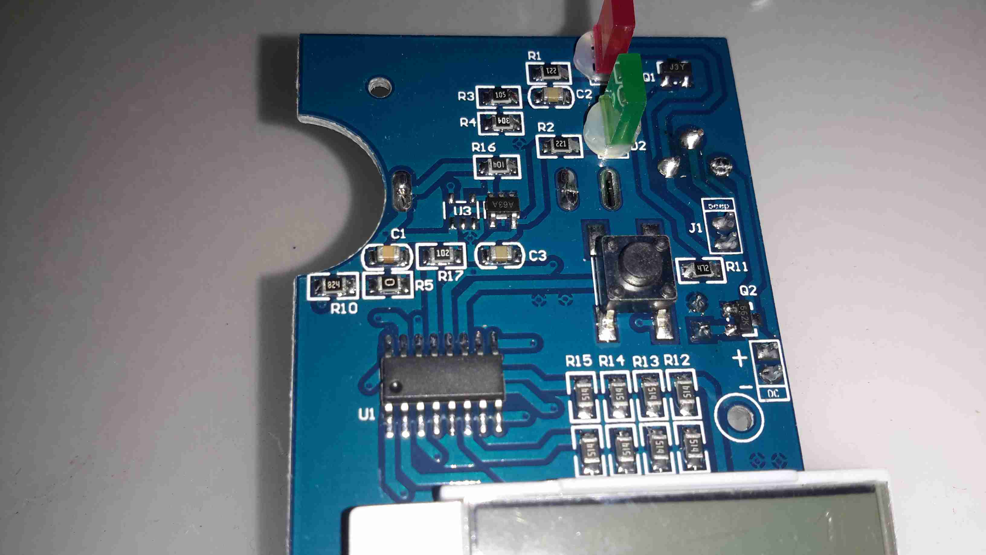
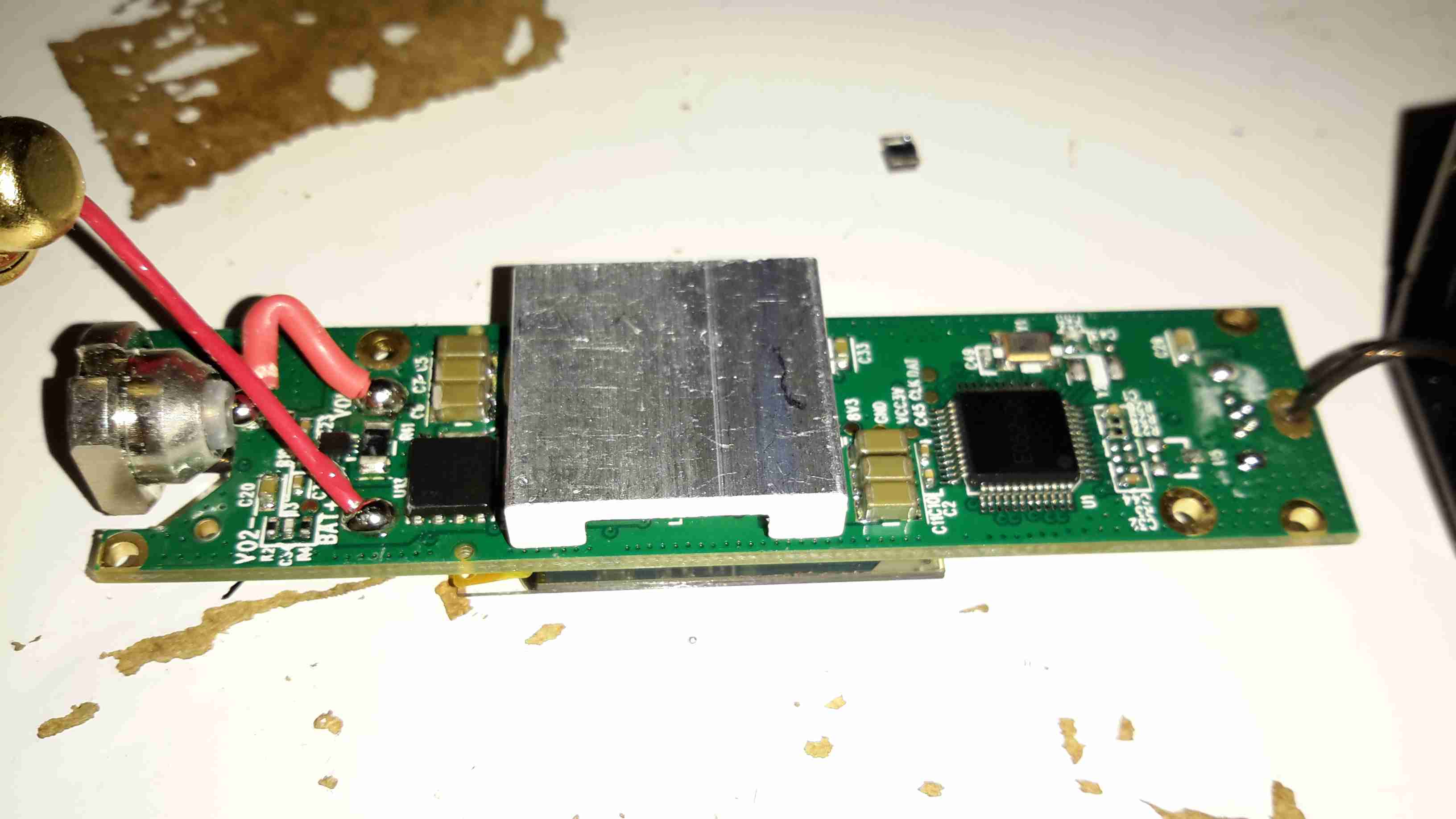
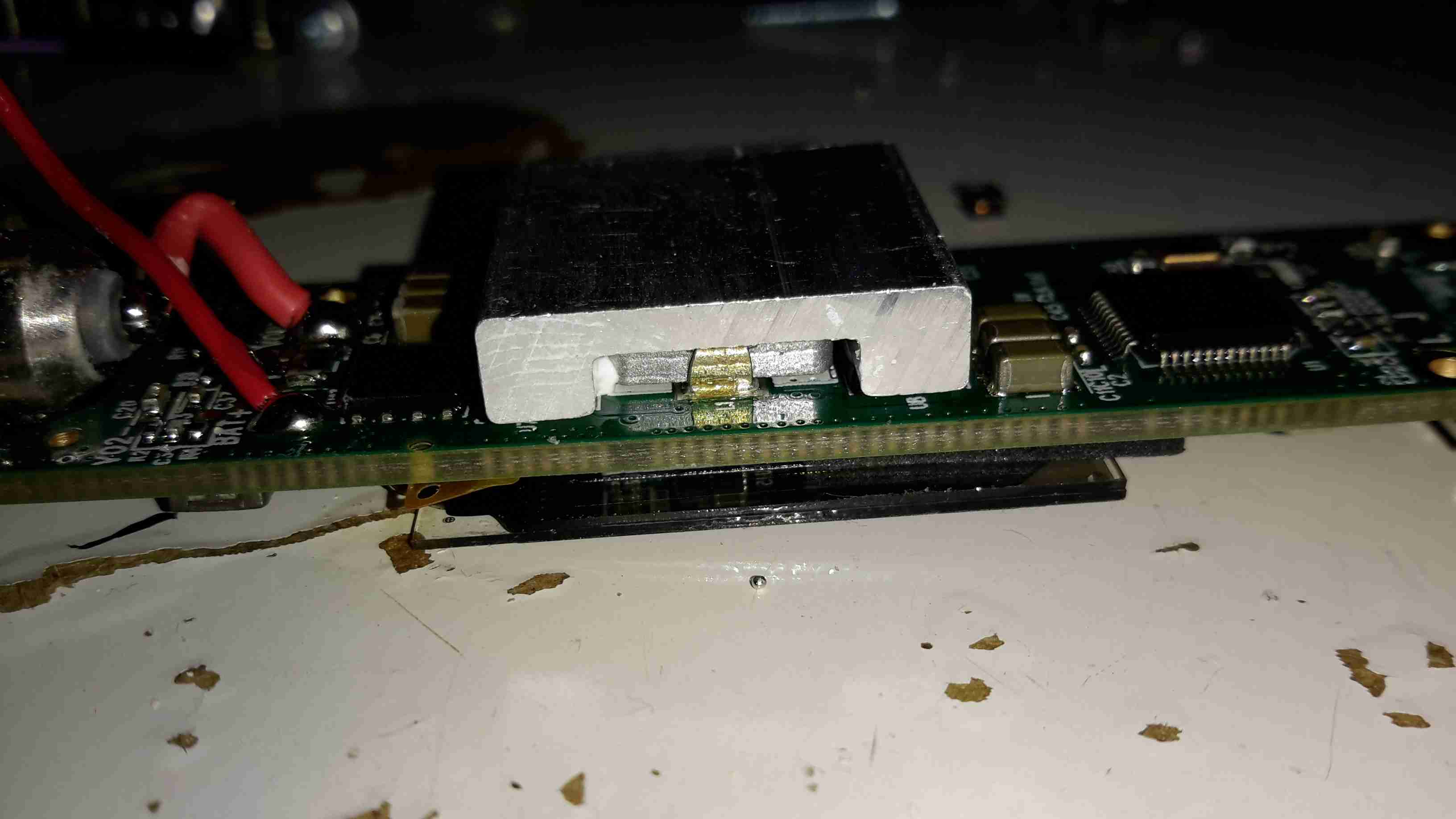
PCB Reverse
Removing the board from the battery holder shows the main power circuitry & MCU. The aluminium heatsink is thermally bonded to the switching MOSFETs, a pair under each end. The switching inductor is under the gap in the centre of the heatsink.
DC-DC Converter
A close up of the heatsink shows the very slim inductor under the heatsink.
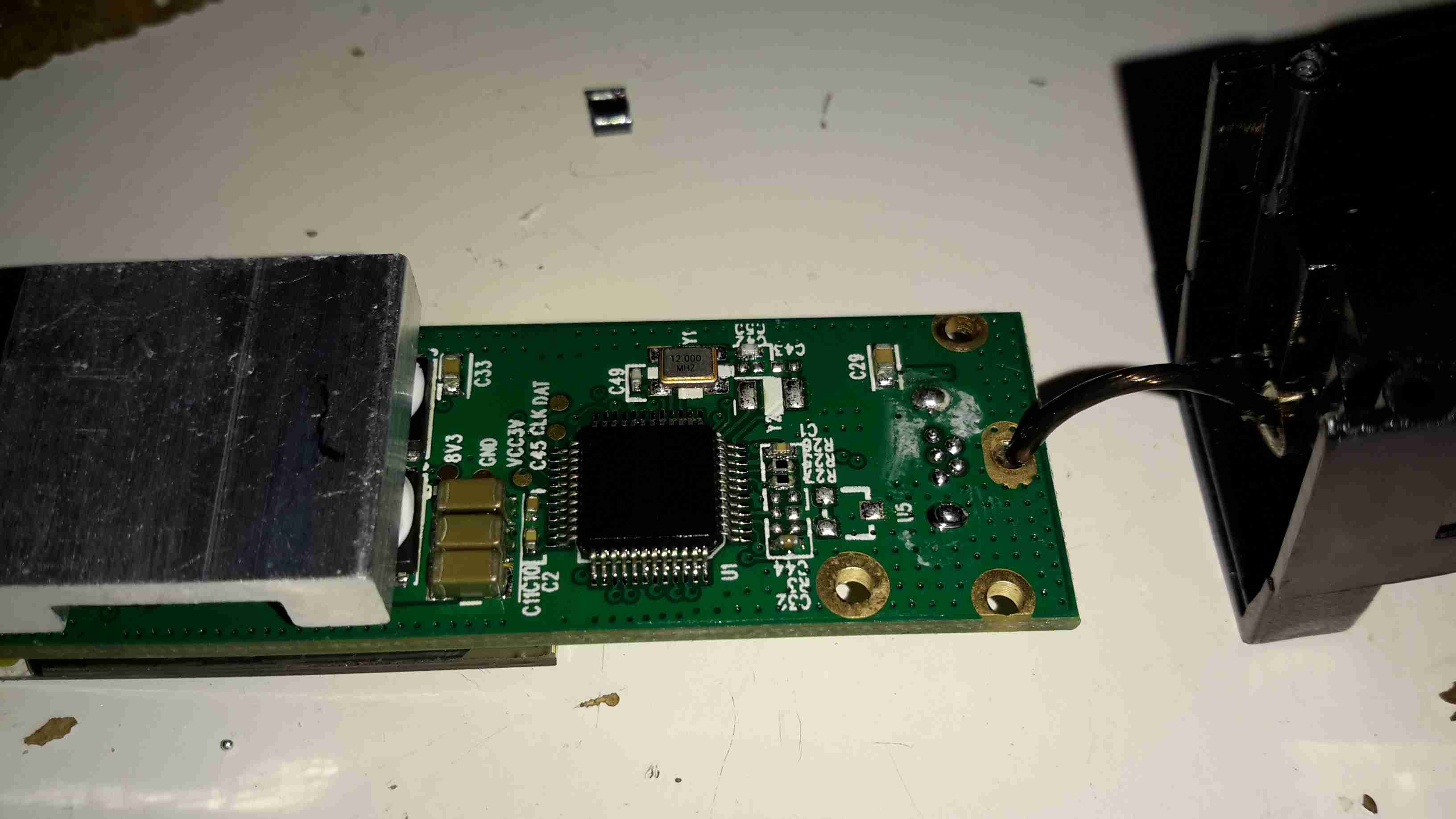
Microcontroller
The main MCU in this unit has a very strange part number, which I’ve been unable to find information on, but it’s probably 8081 based.
One bit of my equipment that I’ve never looked into is my scanner, a handheld Uniden unit. I got this when Maplin Electronics had them on special offer a few years ago.
Uniden Scanner
Here’s the scanner itself, roughly the same size as a usual HT.
Back Cover Removed
Here the back cover has been removed, and the main RF board is visible at the top of the stack. Unfortunately the shielding cans are soldered on this unit, so no looking under there 🙁
On the right hand side of the board next to the antenna input is the main RF filter network, and it’s associated switching. The RF front end is under the shield closest to the front edge.
Controls & 3.3v Regulator
On the other side of the PCB is the Volume & Squelch potentiometers, along with a dedicated 3.3v switching supply. An NJM2360A High Precision DC/DC converter IC controls this one. A 3.3v test point is visible next to the regulator.
RF Board Reverse
Here’s the backside of the RF board, some more interesting parts here. There’s a pair of NJM3404A Single Supply Dual Op-Amp ICs, and a TK10931V Dual AM/FM IF Discriminator IC. This is the one that does all the back-end radio functionality. The audio amplifier for the internal speaker & external headphone jack is also on this PCB, top left. A board-to-board interconnect links this radio board with the main control board underneath.
Control PCB Front
Here’s the front of the control PCB, nothing much to see here, just the LCD & membrane keypad contacts.
Control PCB Reverse
And here’s the reverse side of the control board. All the interesting bits are here. The main microcontroller is on the right, a Renesas M38D59GF, a fairly powerful MCU, with onboard LCD drive, A/D converter, serial interface, 60K of ROM & 2K of RAM. It’s 6.143MHz clock crystal is just below it.
The mating connector for the RF board is in the centre here.
There is also a Microchip 24LC168 16KB I²C EEPROM next to the main microcontroller. This is probably for storing user settings, frequencies, etc.
EEPROM
The rest of this board is dedicated to battery charging and power supply, in the centre is a dual switching controller, I can’t figure out the numbers on the tiny SOT23 components in here, but this is dealing with the DC 6v input & to the left of that is the circuitry for charging the NiMH cells included with the scanner.
PSU
The last bit of this PCB is a BU2092FV Serial In / Parallel Out 4 channel driver. Not sure what this one is doing, it might be doing some signal multiplexing for the RF board interface. Unfortunately the tracks from this IC are routed on the inner layers of the board so they can’t be traced out.
It’s official. I’m now part of the uRadMonitor network, & assisting in some of the current issues with networking some people (including myself) have been having.
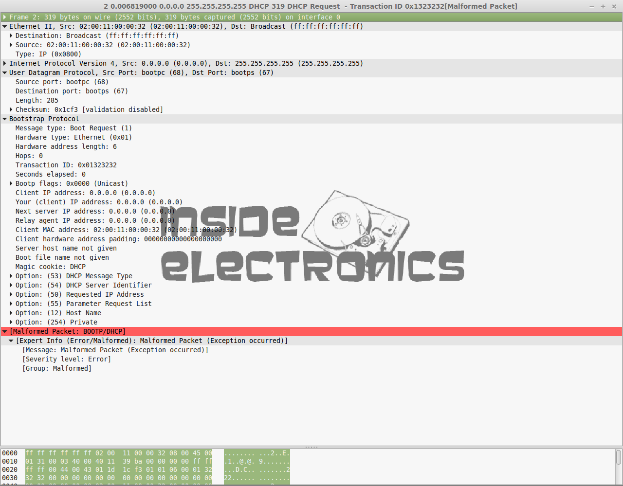
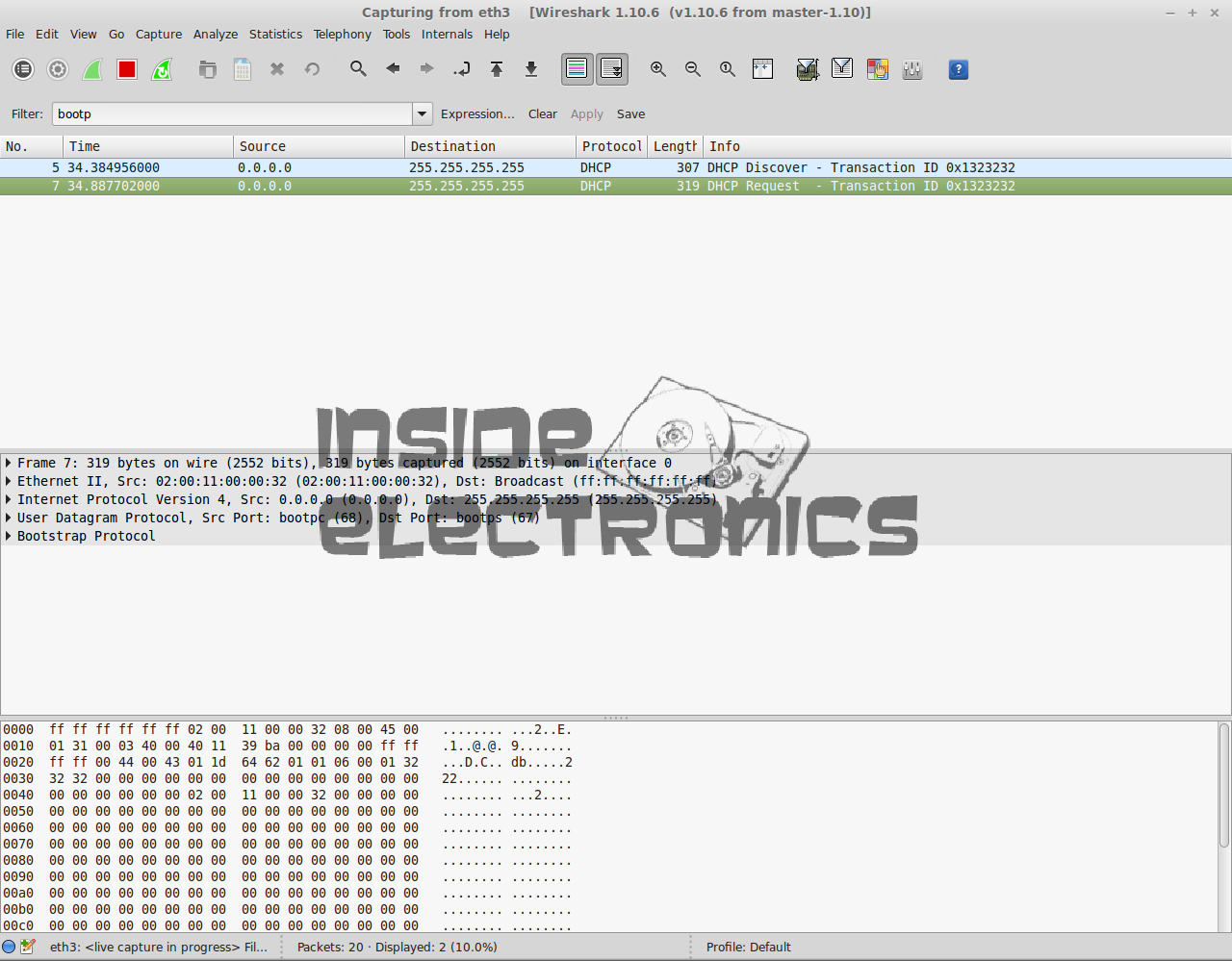
It seems that the uRadMonitor isn’t sending out technically-valid DHCP requests, here is what Wireshark thinks of the DHCP on my production network hardware setup:
WireShark Screencap
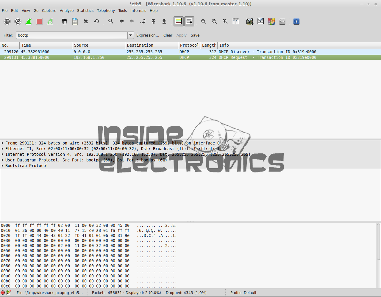
As can be seen, the monitor unit is sending a DHCP request of 319 bytes, where a standard length DHCP Request packet should be ~324 bytes, as can be seen on the below screen capture.
Valid DHCP
This valid one was generated from the same SPI Ethernet module as the monitor, (Microchip ENC28J60) connected to an Arduino. Standard example code from the EtherCard library was used to set up the DHCP. The MAC address of the monitor was also cloned to this setup to rule out the possibility of that being the root cause.
My deductive reasoning in this case points to the firmware on the monitor being at fault, rather than the SPI ethernet hardware, or my network hardware. Radu over at uRadMonitor is looking into the firmware being at fault.
Strangely, most routers don’t seem to have an issue with the monitor, as connecting another router on a separate subnet works fine, and Wireshark doesn’t even complain about an invalid DHCP packet, although it’s exactly the same.
Working DHCP
As the firmware for the devices isn’t currently available for me to pick apart & see if I can find the fault, it’s up to Radu to get this fixed at the moment.
Now, for a µTeardown:
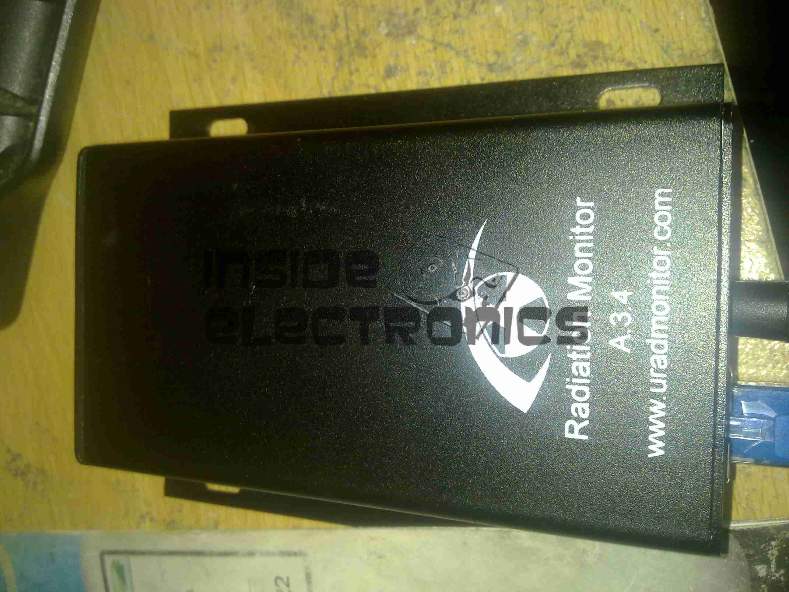
uRadMonitor
Here is the monitor, a small aluminium box, with power & network.
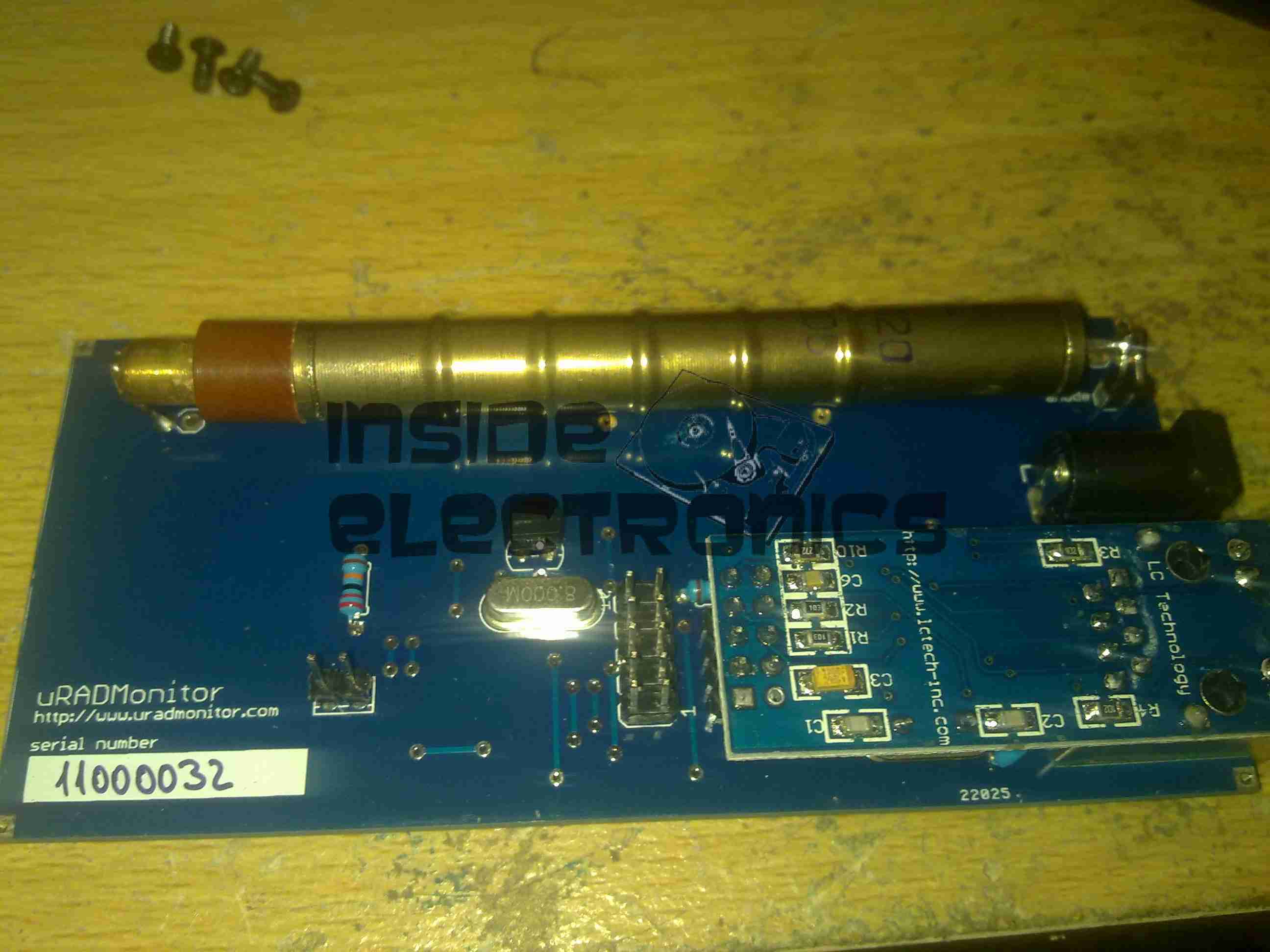
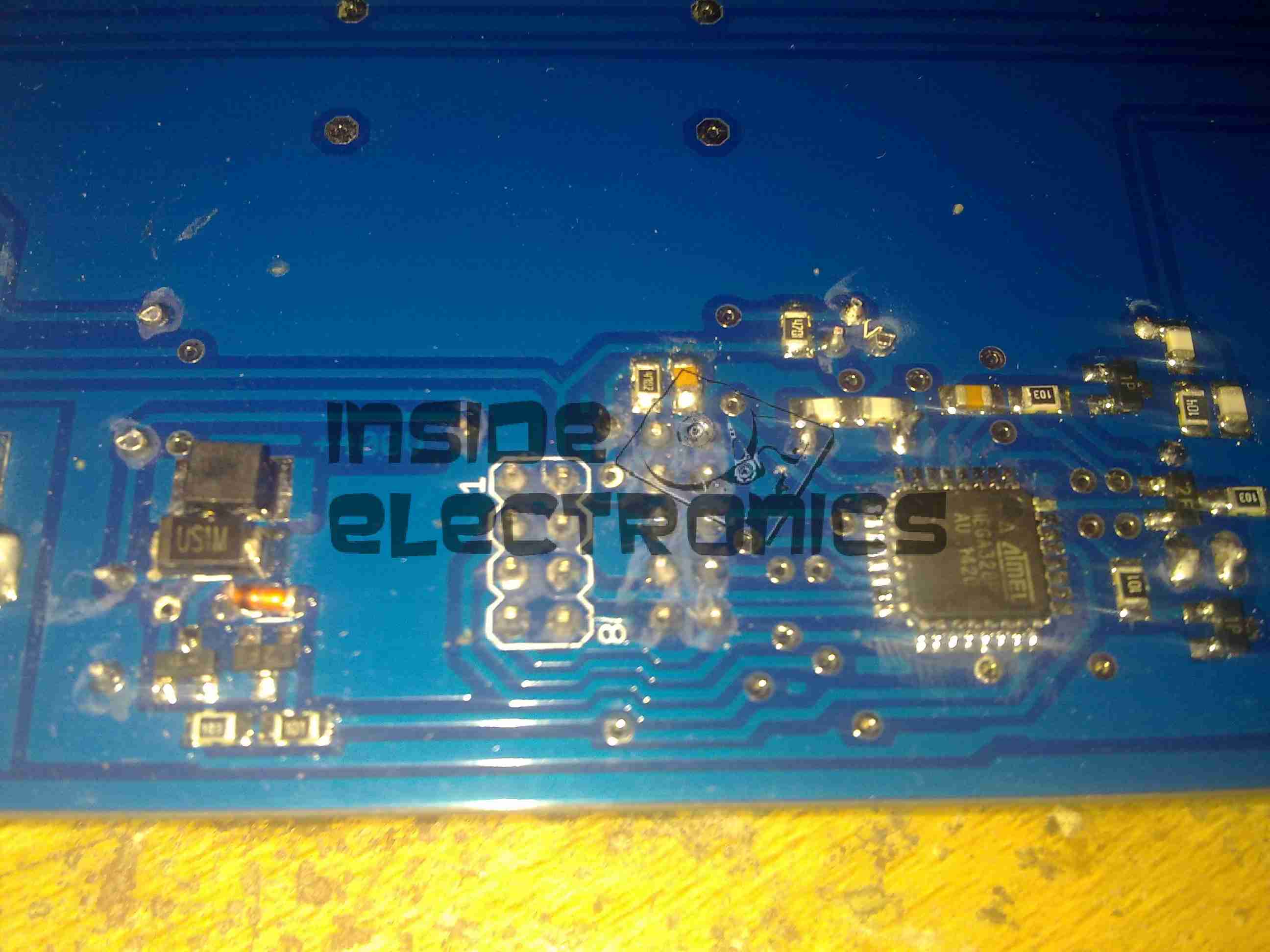
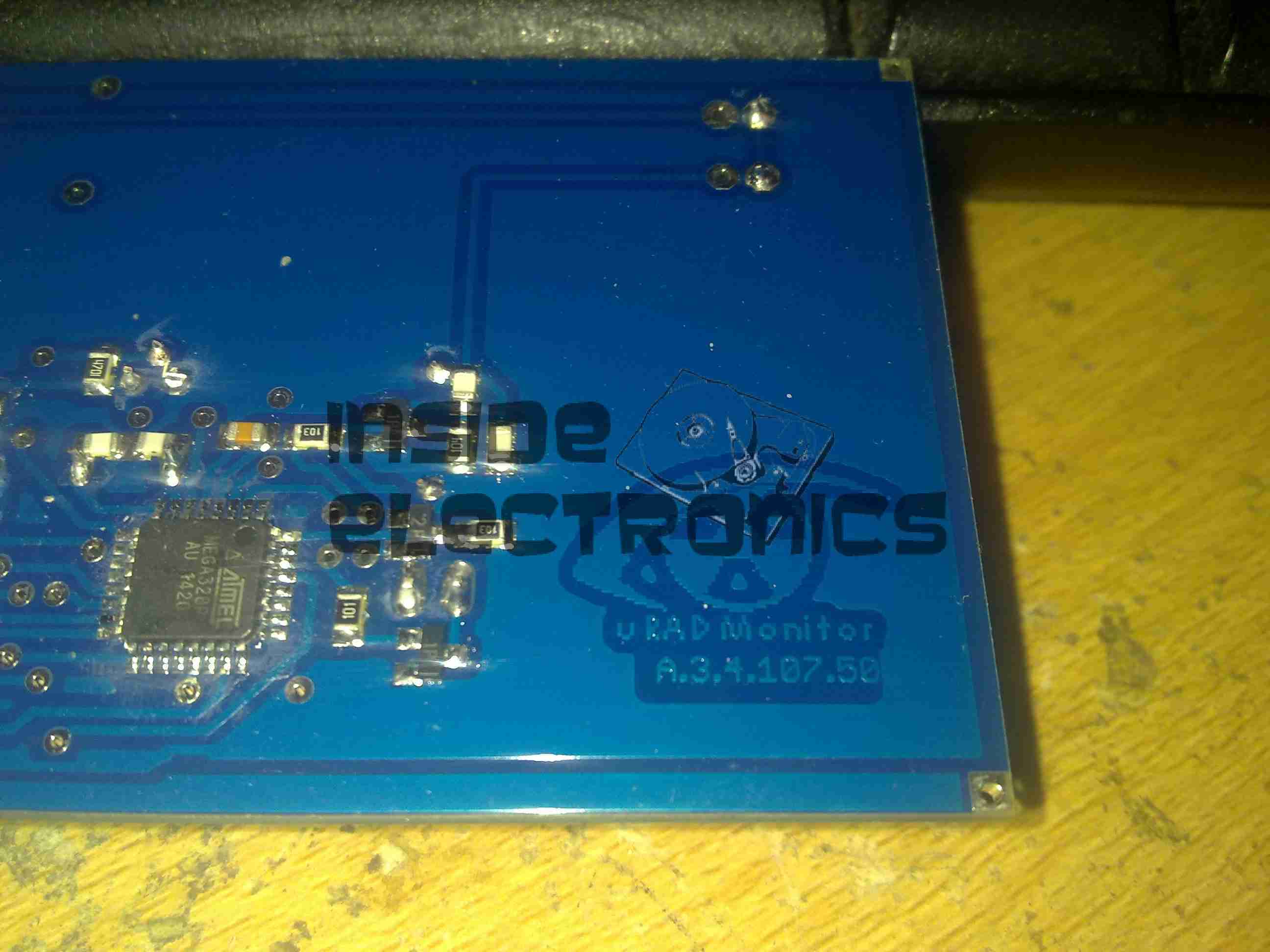
PCB
Removing 4 screws in the end plate reveals the PCB, with the Geiger-Mueller tube along the top edge. My personal serial number is also on the PCB.
The ethernet module is on the right, with the DC barrel jack.
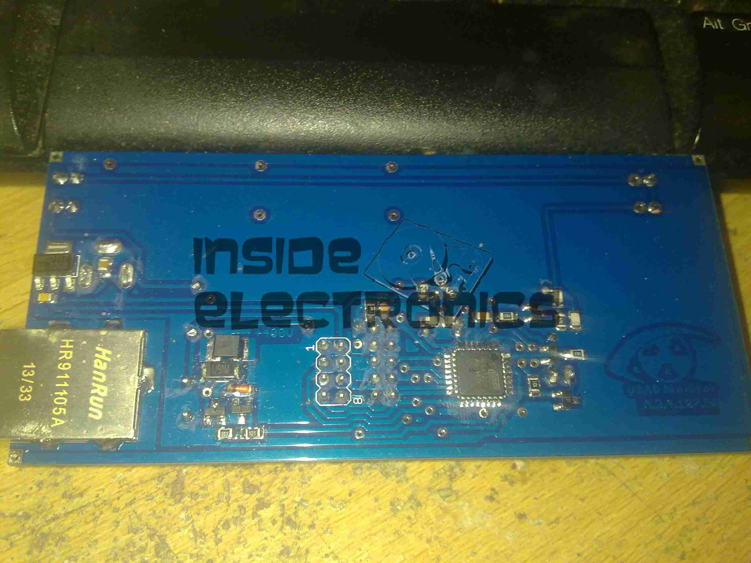
PCB Bottom
Here is the bottom of the PCB, with the control MCU & the tiny high voltage inverter for the Geiger tube.
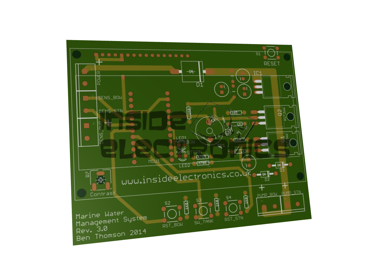
OK, a few revisions have been made to the water management PCB, mainly to reduce the possibility of the brushed DC motors in the water pumps from causing the MCU to crash, with the other changes to the I/O connector positioning & finally upgrading the reverse blocking diode to a 10A capable version rather than 5A.
Here is a label maker, bought on offer at Maplin Electronics. Full Qwerty keyboard with 1 line dot matrix LCD display visible here. Power is 4 AAA cells or a 6v DC Adaptor.
Rear
Rear cover removed. Battery compartment is on the left hand side, space for the tape cartridge on the right. Ribbon cable leading to the thermal print head is on the far right, with rubber tape drive roller.
PCB
PCB under the top cover with the main CPU, a MN101C77CBM from Panasonic. This CPU features 48K Mask ROM & 3K of RAM. Max clock frequency is 20MHz. 32kHz clock crystal visible underneath a Rohm BA6220 Electronic speed controller IC.
This is used to drive the printer motor at a constant accurate speed, to feed the tape past the thermal head. Miniature potentiometer adjusts speed.
Ribbon cable at the bottom of the board connects to the print head, various wiring at the left connects to the battery & DC Jack.
Printer Drive
Printer drive mechanism. Small DC motor drives the pinch roller though a gear train. DC Jack & reverse polarity protection diode is on the right.
This unit uses a centre negative DC jack, which is unusual.
Cartridge
Thermal tape cartridge, black text on white background.
This is an old cordless landline phone, with dead handset batteries.
Handset Radio Board
Here’s the handset with the back removed. Shown is the radio TX/RX board, underneath is the keyboard PCB with the speaker & mic. All the FM radio tuning coils are visible & a LT450GW electromechanical filter.
Handset Radio Board Bottom
Radio PCB removed from the housing showing the main CPU controlling the unit, a Motorola MC13109FB.
Keypad Board
The keypad PCB, with also holds the microphone & speaker.
Handset Keypad Board Bottom
Bottom of the keypad board, which holds a LSC526534DW 8-Bit µC & a AT93C46R serial EEPROM for phone number storage.
Base Main Board
Here’s the base unit with it’s top cover removed. Black square object on far right of image is the microphone for intercom use, power supply section is top left, phone interface bottom left, FM radio is centre. Battery snap for power backup is bottom right.
Power Supply Section
PSU section of the board on the left here, 9v AC input socket at the bottom, with bridge rectifier diodes & main filter capacitor above. Two green transformers on the right are for audio impedance matching. Another LT450GW filter is visible at the top, part of the base unit FM transceiver.
ICs
Another 8-bit µC, this time a LSC526535P, paired with another AT93C46 EEPROM. Blue blob is 3.58MHz crystal resonator for the MCU clock. The SEC IC is a KS58015 4-bit binary to DTMF dialer IC. This is controlled by the µC.
Base Main Board Bottom
Underside of the base unit Main PCB, showing the matching MC13109FB IC for the radio functions.
Tip Jar
If you’ve found my content useful, please consider leaving a donation by clicking the Tip Jar below!
All collected funds go towards new content & the costs of keeping the server online.