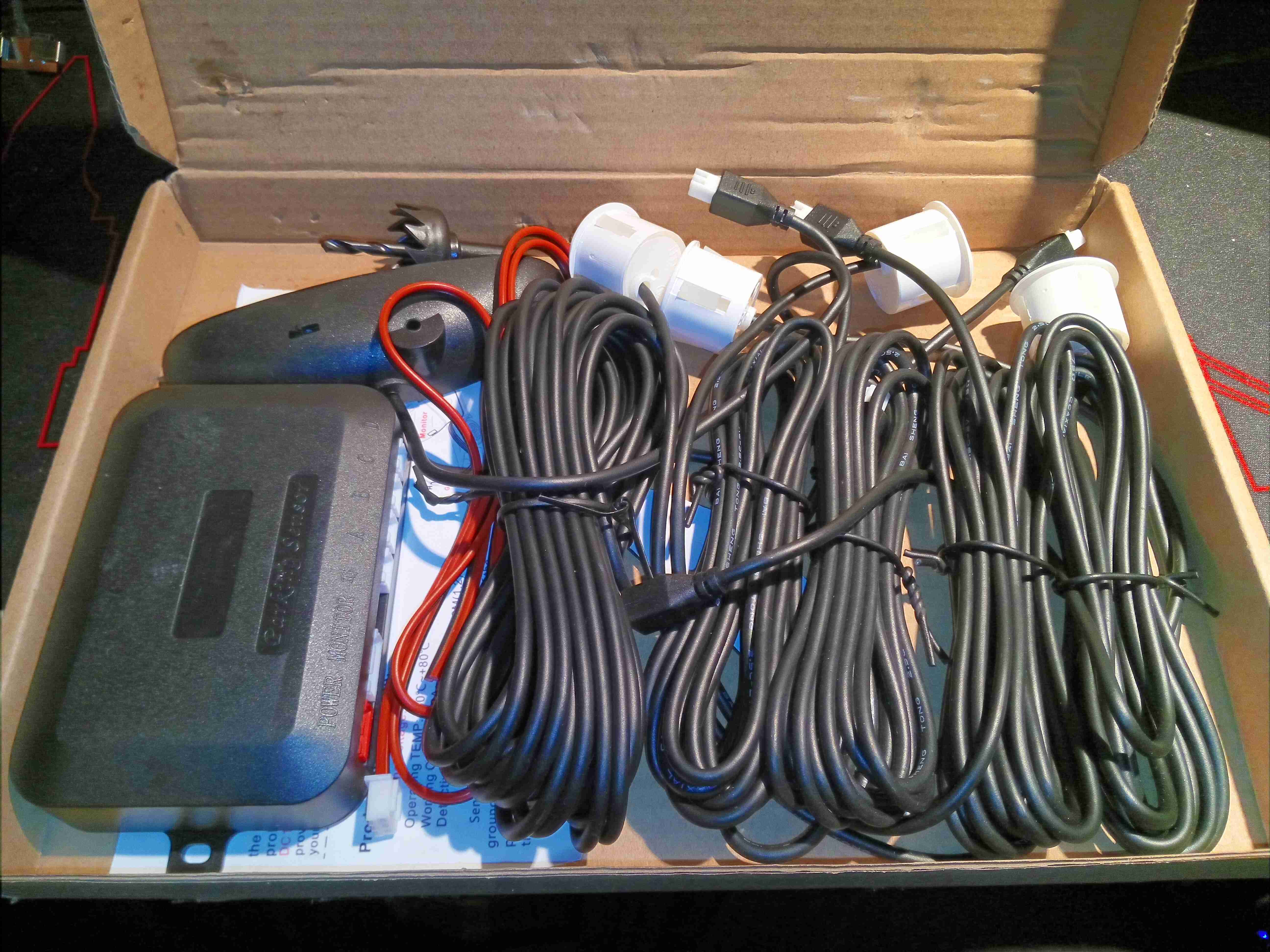
This is a cheap kit from eBay, to retrofit an older car with ultrasonic parking sensors. 4 sensors are included in the kit, along with a hole saw to fit them to the bumper. There’s a small controller module, and a display module that fits onto the dash of the car.
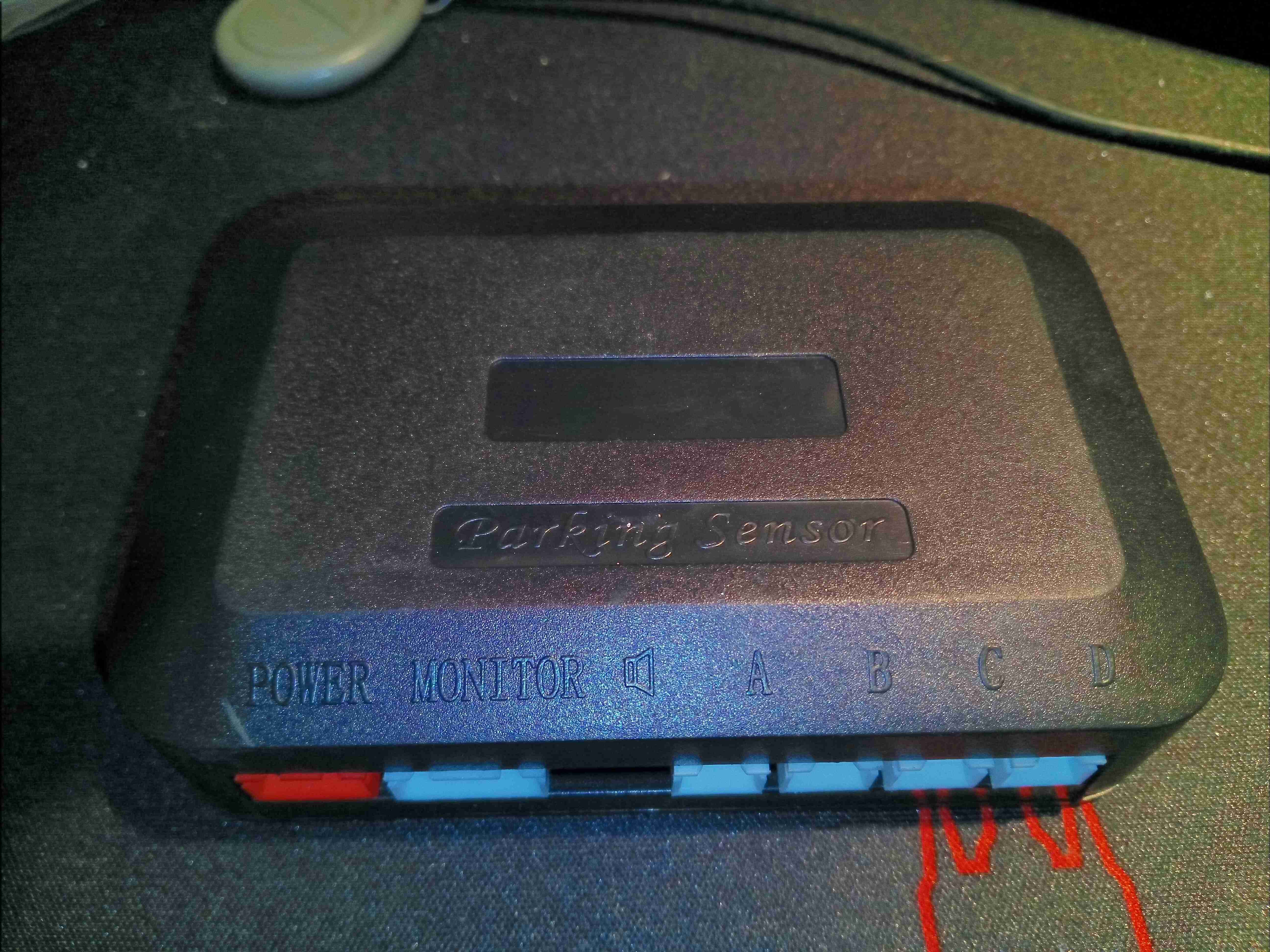
Controller Module
Here’s the controller module, with it’s row of connectors along the front. The unit gets it’s power from the reversing light circuit, via the red connector.
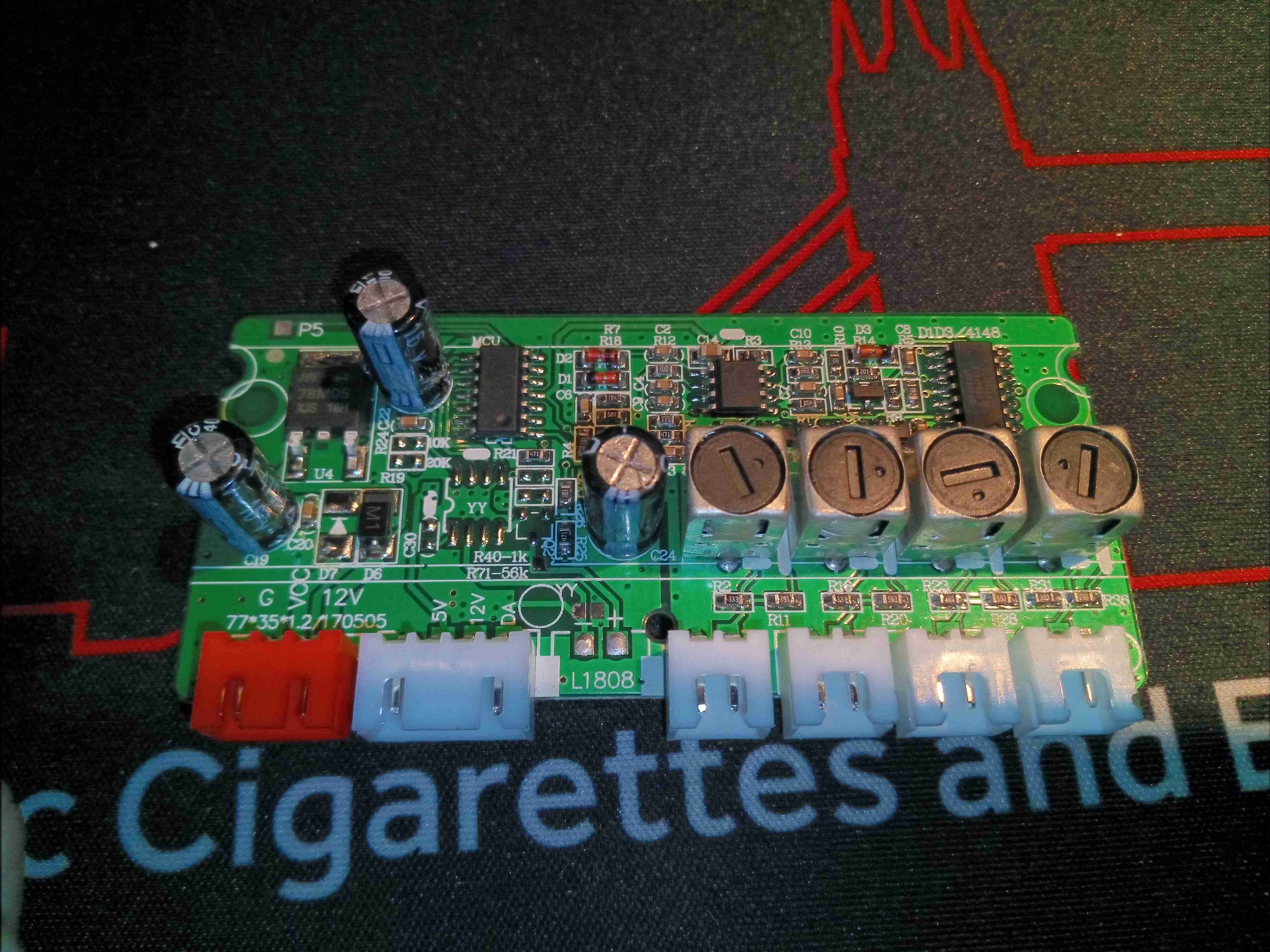
Main Controller PCB
Removing a couple of screws allows the PCB to be removed. There’s quite a bit on this board, including 4 tunable inductors for the ultrasonic transducers. There’s a linear voltage regulator on the left which supplies power to the electronics, and a completely unmarked microcontroller.
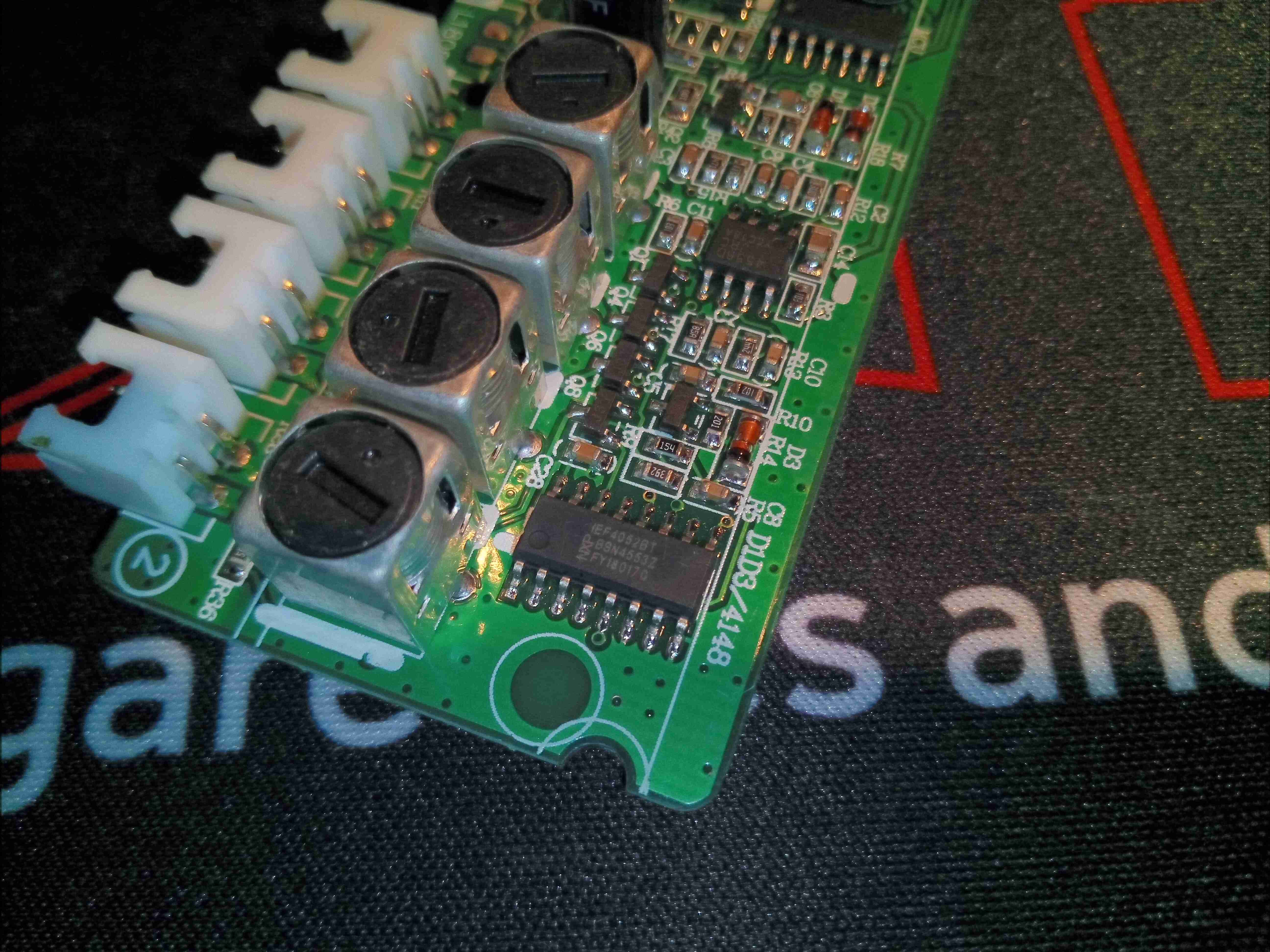
Electronics Closeup
A closer look at the analogue end of the board shows a JRC4558D dual Op-Amp, and an NXP HEF4052B analogue multiplexer. As the microcontroller is unmarked I have no data for that one.
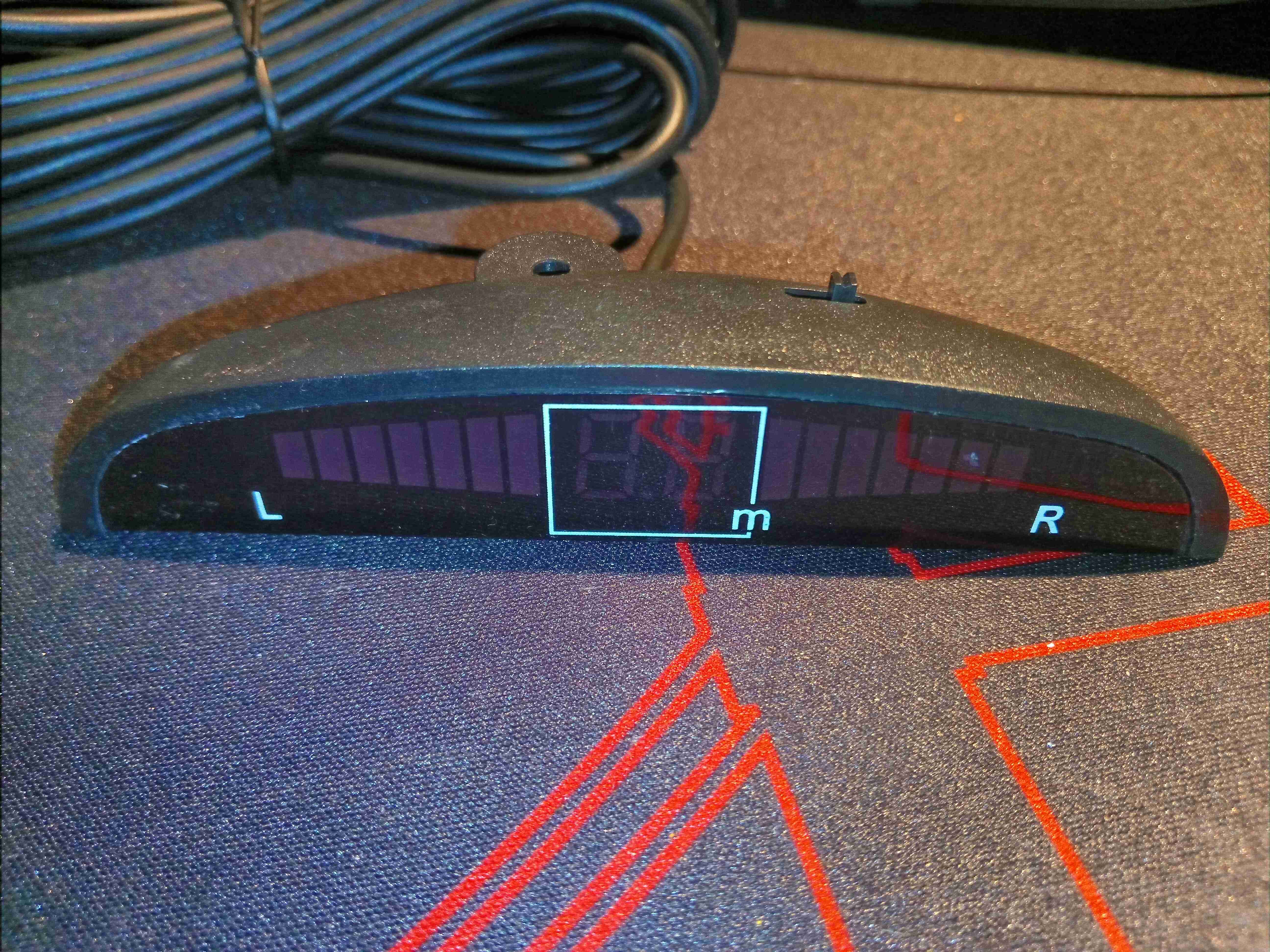
Dash Display
The dash display is housed in another small plastic box, with bargraphs for each side of the car & an overall distance meter.
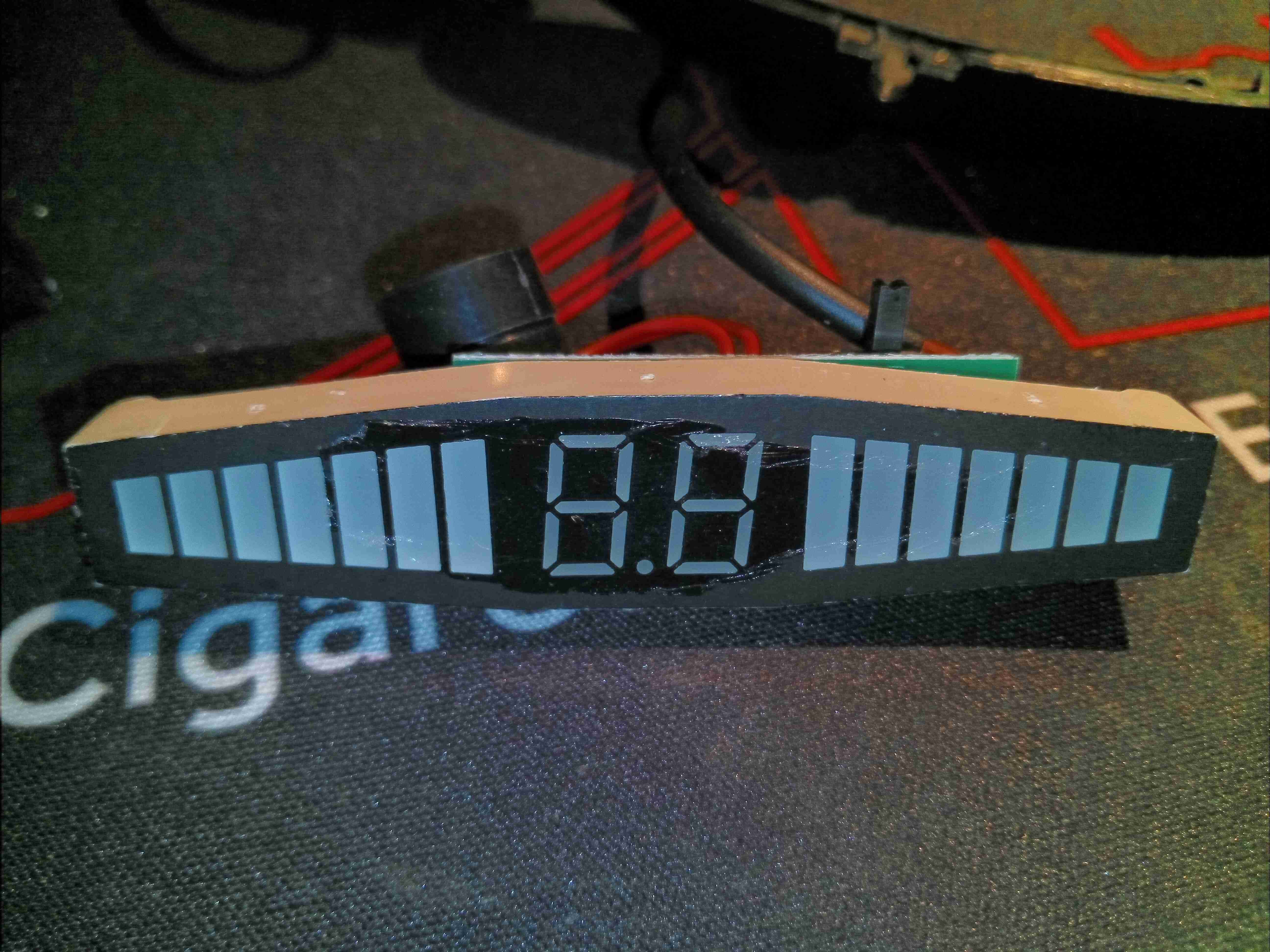
Display Module
Clearly this is a custom module, with the tapered bargraph LEDs on each side & the 7-segment display in the centre. There’s a beeper which works like every factory-fitted unit does, increasing in rate as the distance closes.
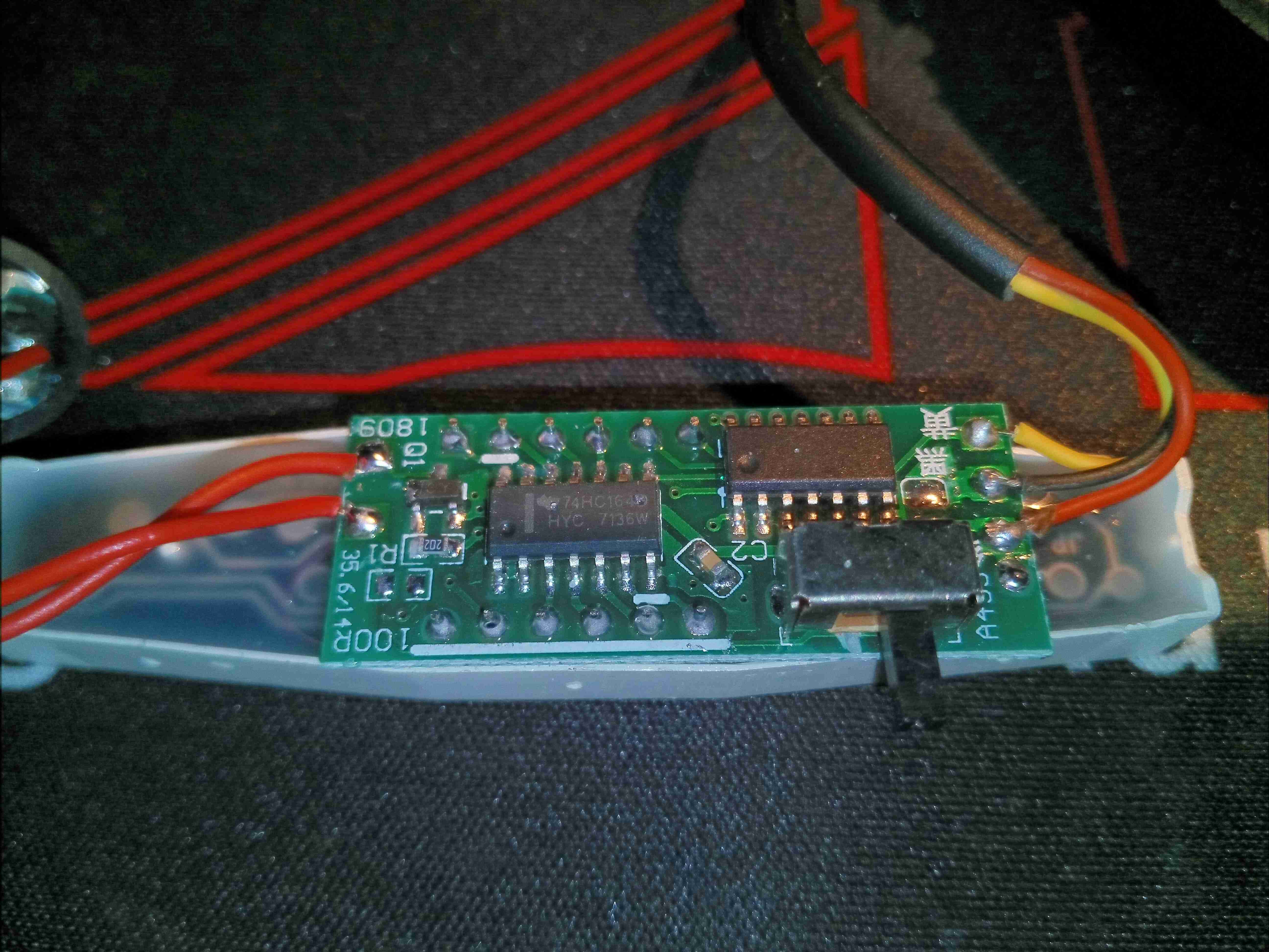
Display PCB
The back of the display module has the driver PCB, with yet another unmarked microcontroller, and a TI 74HC164 serial shift register as a display driver. There’s only 3 wires in the loom from the controller, so some sort of 1-wire protocol must be being used, while I²C is the most likely protocol to be talking to the display driver circuit. There’s also a small switch for muting the beeper.
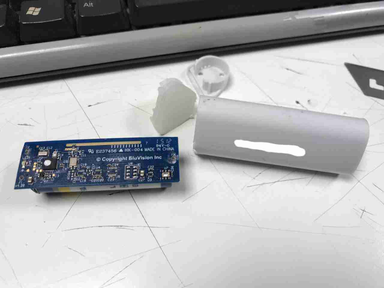
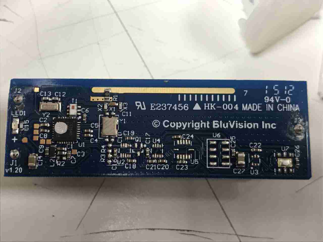
These photos were sent over to me by a friend, an interesting piece of tech that’s used in the retail industry. This is a BluVision BLE Beacon, which as far as I can tell is used to provide some automated customer assistance. From their website it seems they can also be used for high-price asset protection & tracking. These units don’t appear to be serviceable, being completely sealed & only having a primary cell. I’m not sure what they cost but it seems to be an expensive way to contact clients with adverts etc.
Component Side
There’s not much populated on this PCB, the main component here is the CC2640 SimpleLink ultra-low-power wireless microcontroller for Bluetooth Low Energy. It’s a fairly powerful CPU, with an ARM Cortex M3 core, 129KB of flash & up to 48MHz clock speed. There’s a couple of crystals, one of which is most likely a 32,768kHz low-power sleep watch crystal, while the other will be the full clock frequency used while it’s operating. Unfortunately I can’t make the markings out from the photos. There doesn’t appear to be any significant power supply components, so this must be running direct from the battery underneath.
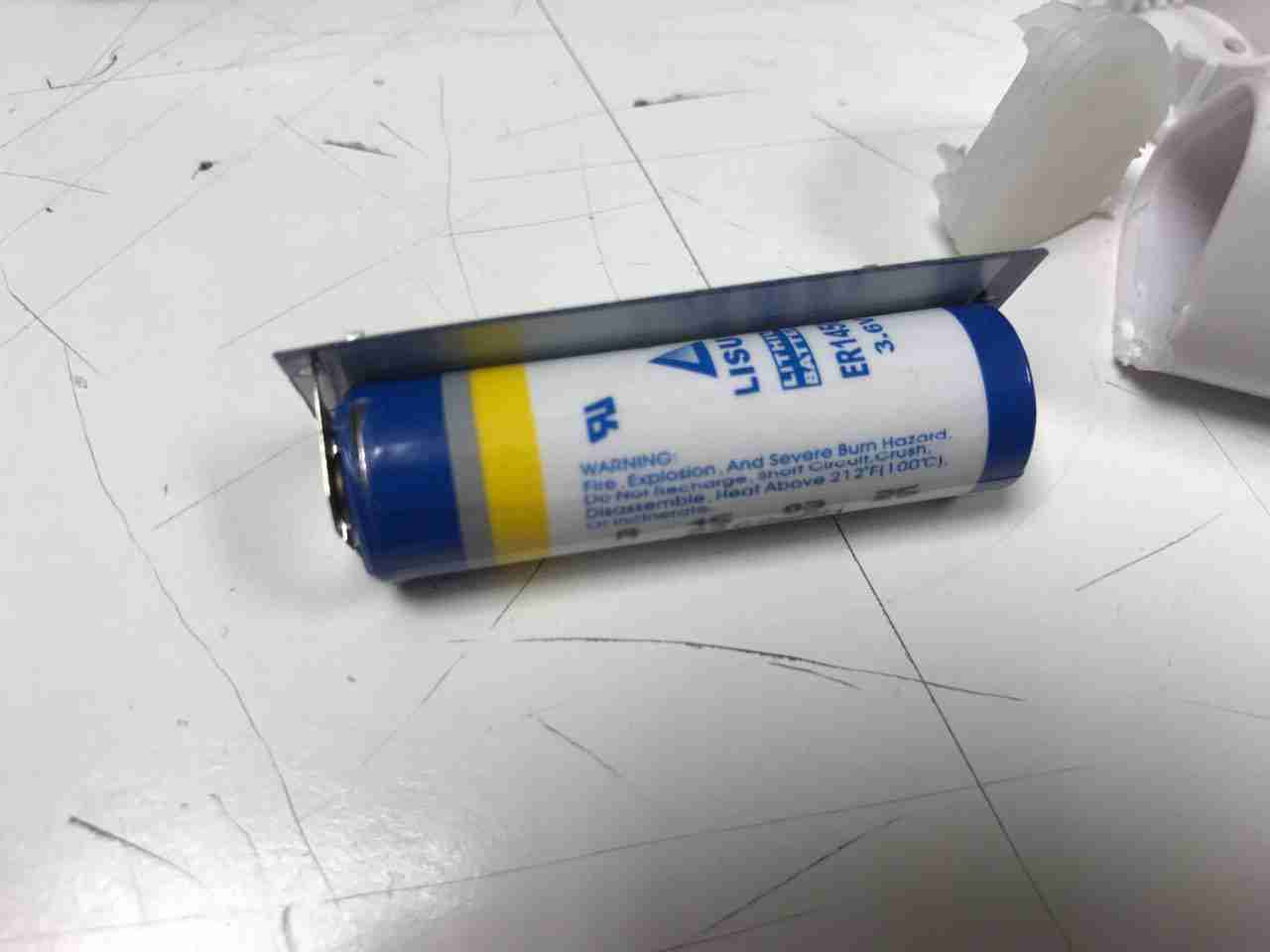
2.2Ah 3.6v Lithium Cell
The other side of the PCB has a single primary lithium cell, rated at 3.6v, 2.2Ah. The factory spec sheet specifies a 2.2 year life at 0dBm TX Power, Running 24/7, 100ms advertisement rate.
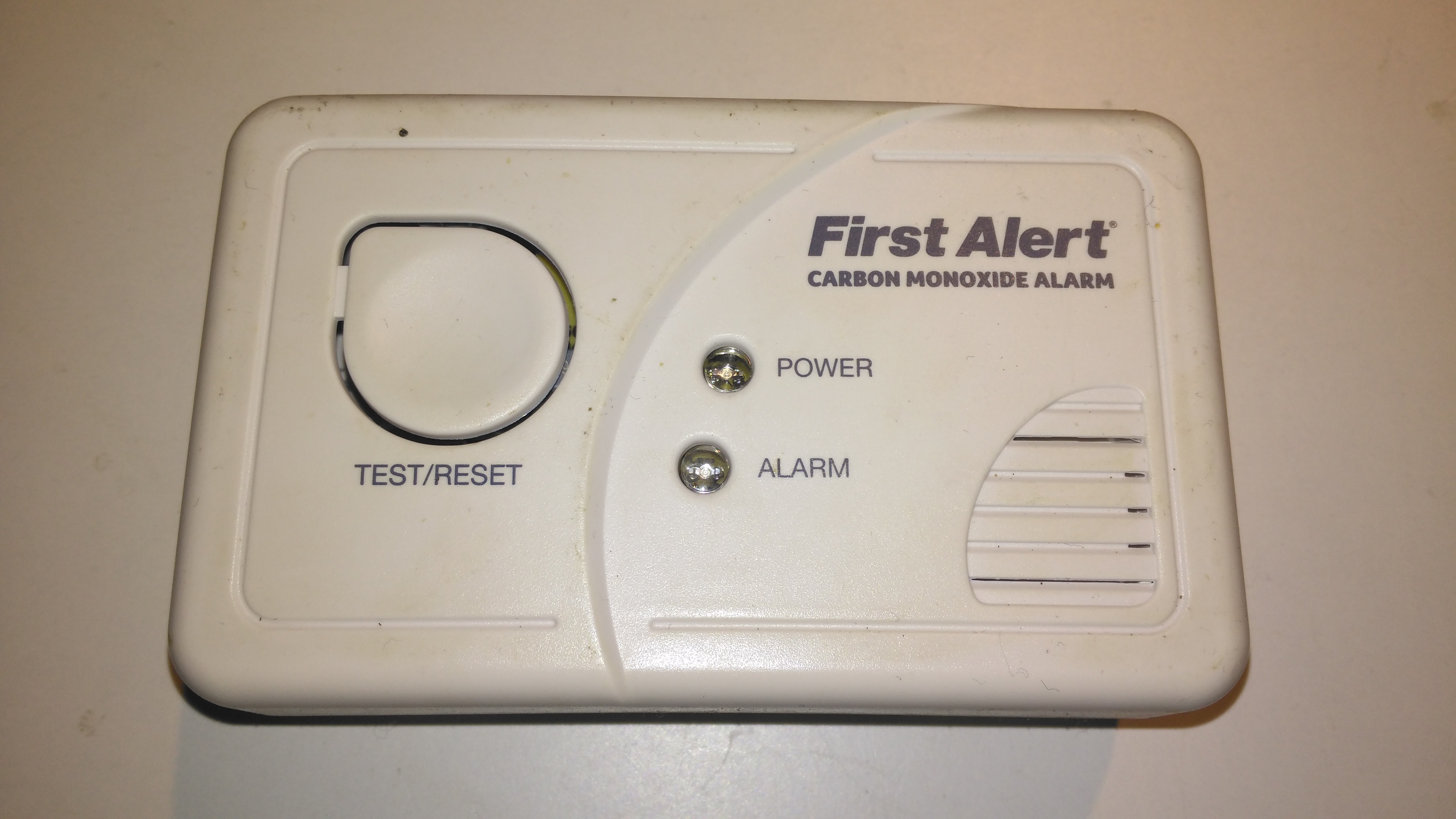
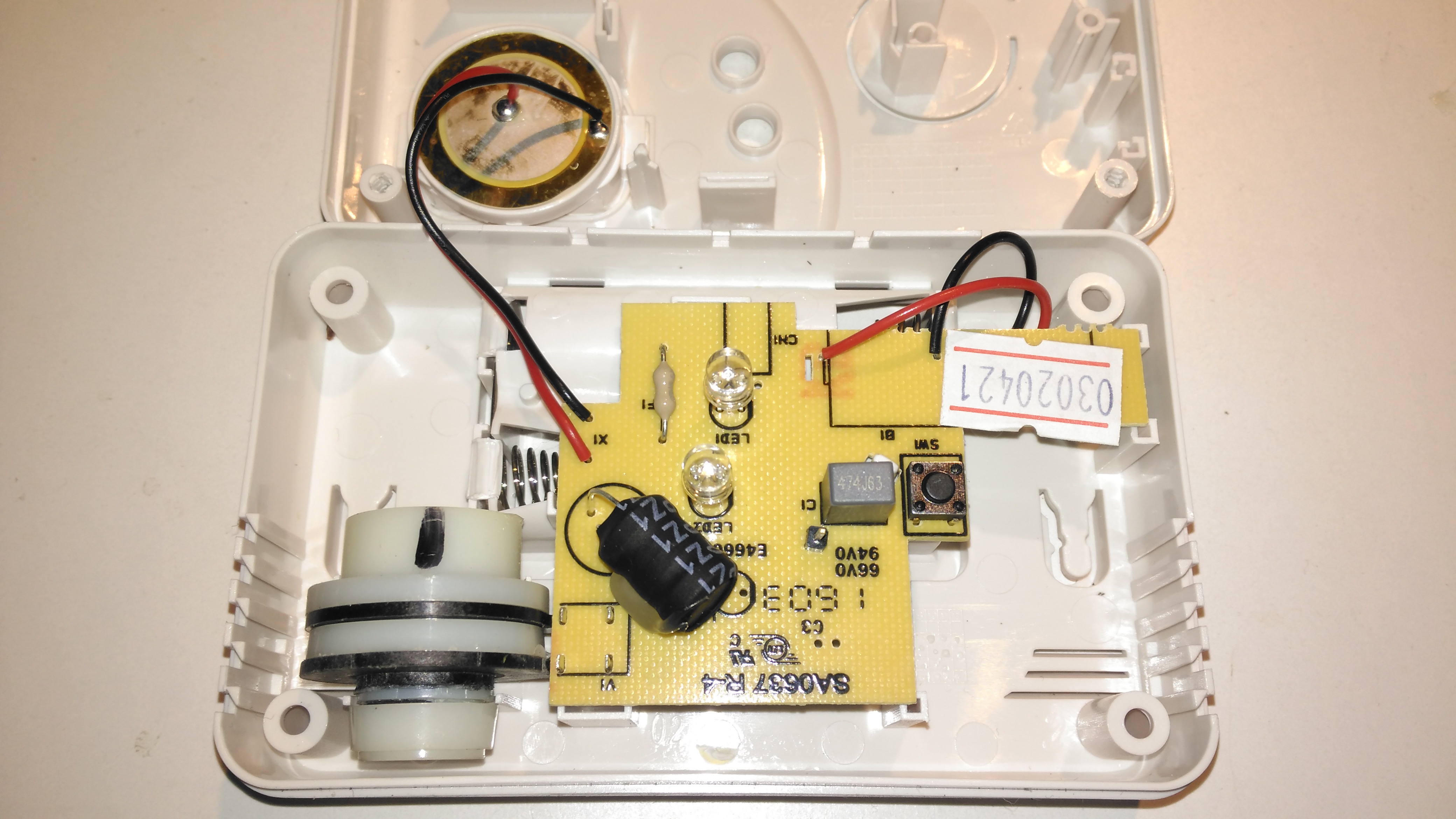
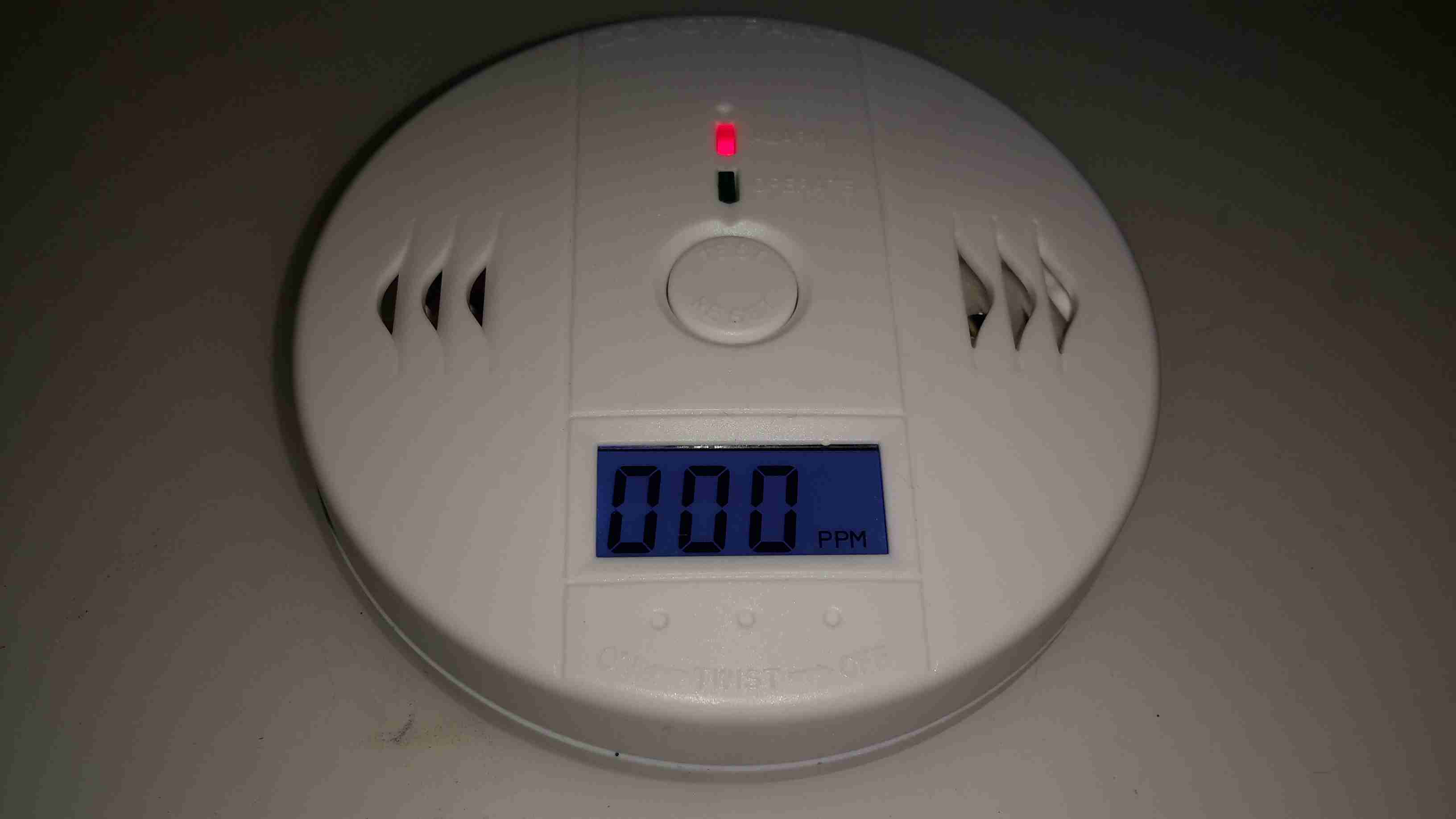
Here’s another domestic CO Alarm, this one a cheaper build than the FireAngel ones usually use, these don’t have a display with the current CO PPM reading, just a couple of LEDs for status & Alarm.
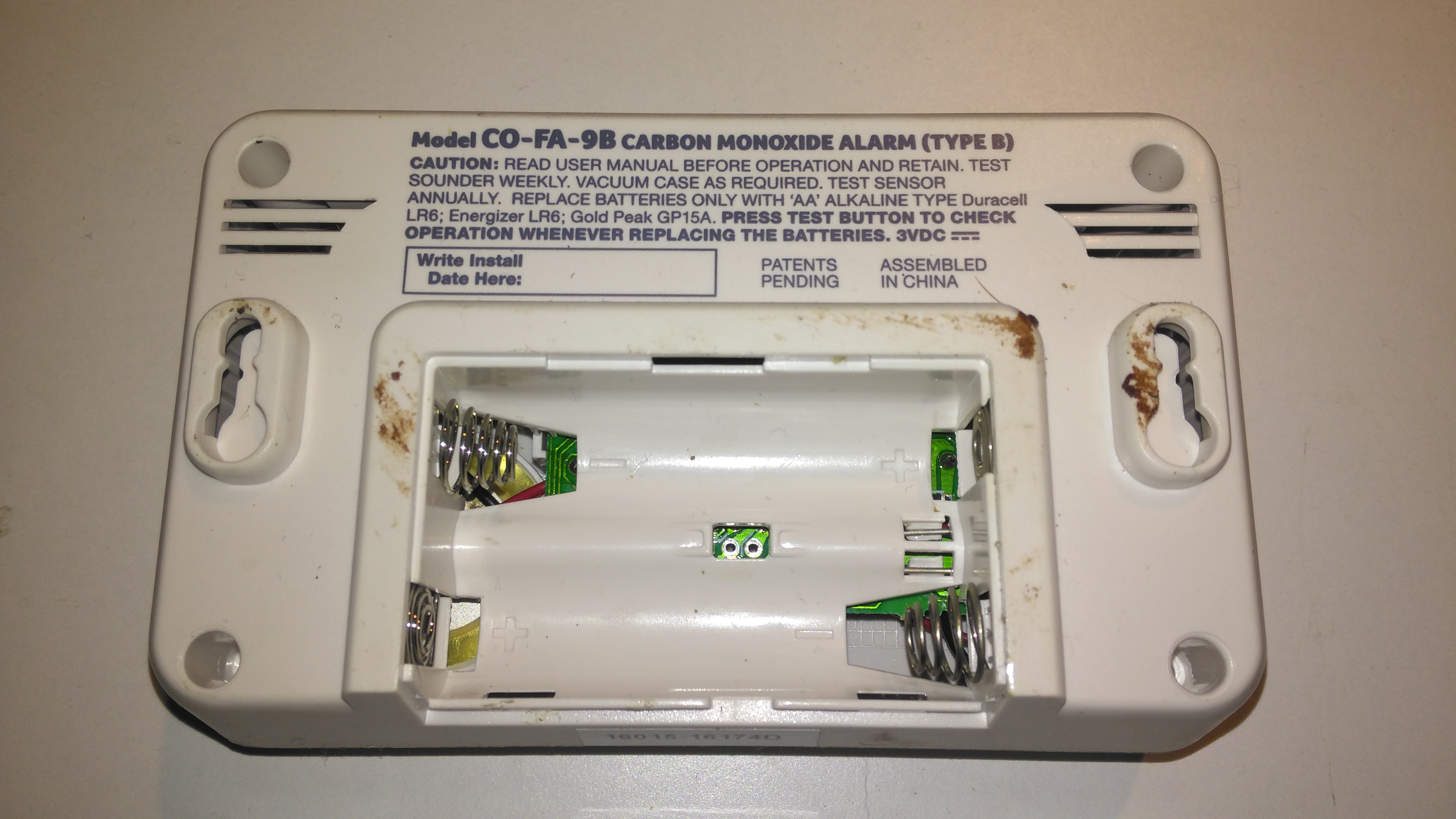
Rear
This alarm also doesn’t have the 10-year lithium cell for power, taking AA cells instead. The alarm does have the usual low battery alert bleeps common with smoke alarms though, so you’ll get a fair reminder to replace them.
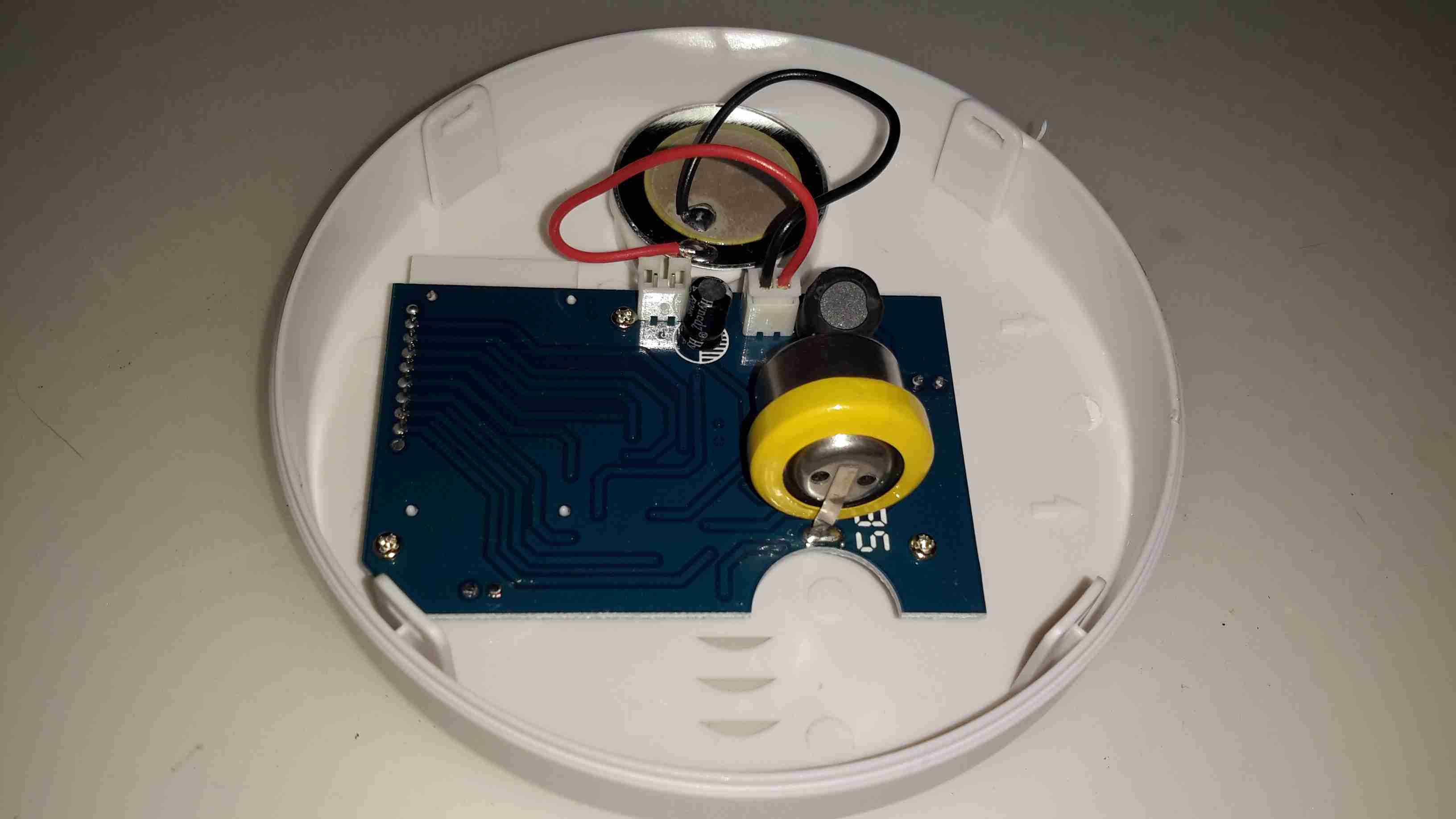
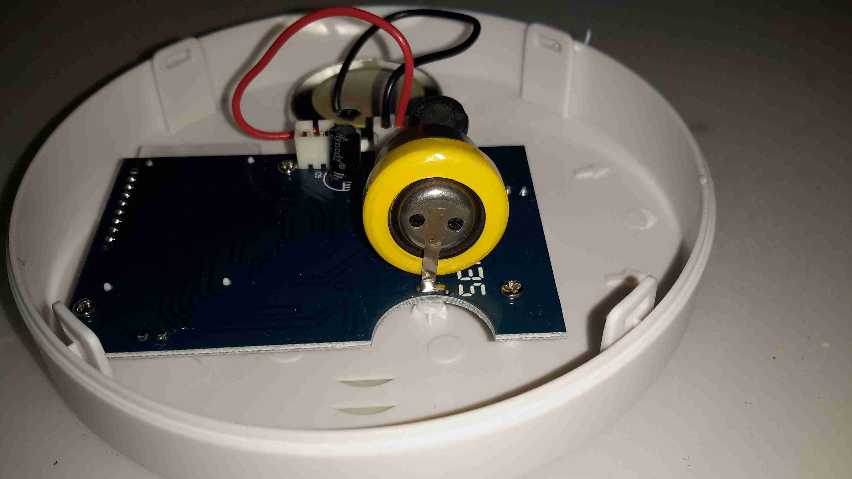
Internals
Not much at all on the inside. The CO sensor cell is the same one as used in the FireAngel alarms, I have never managed to find who manufactures these sensors, or a datasheet for them unfortunately.
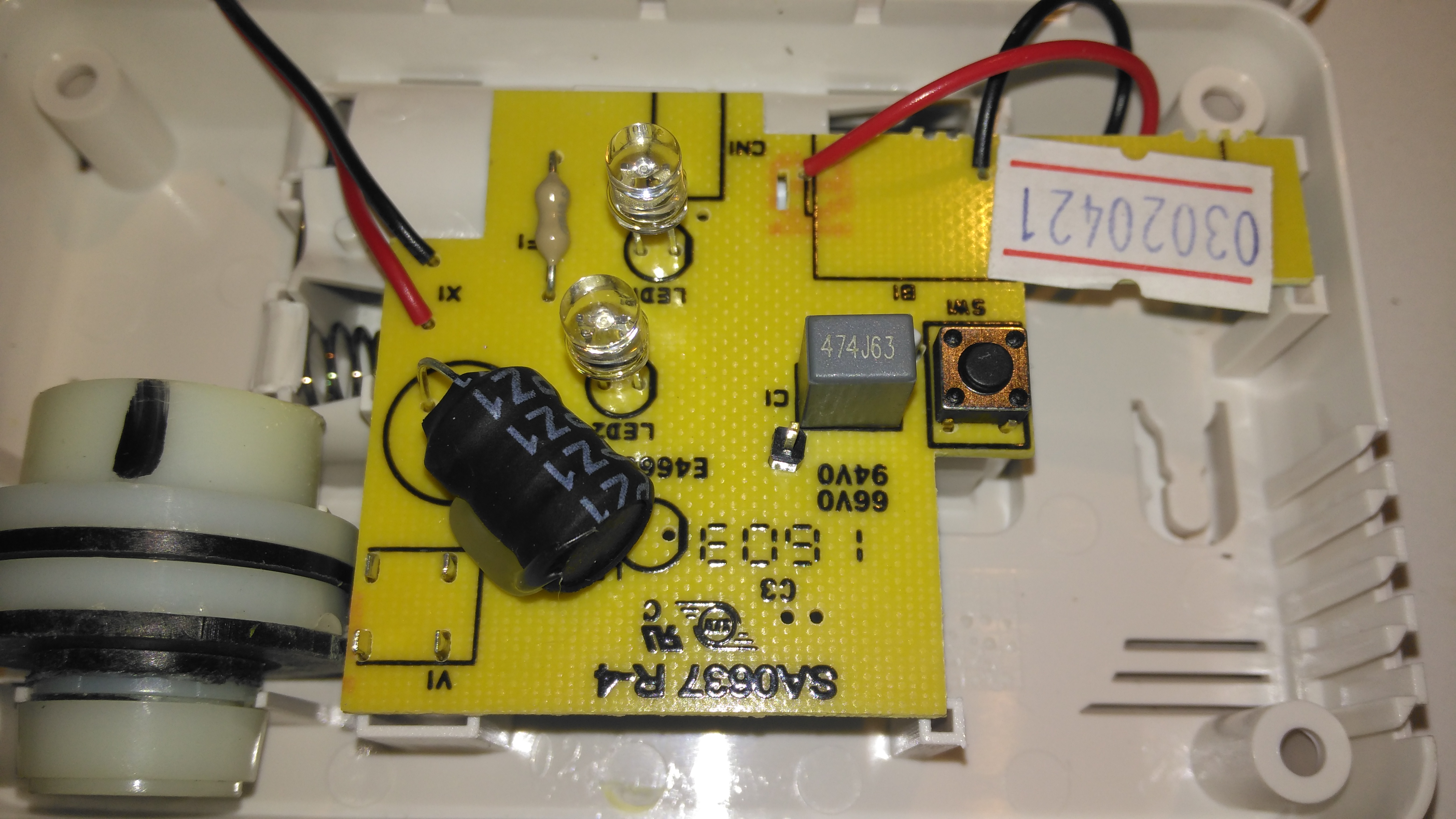
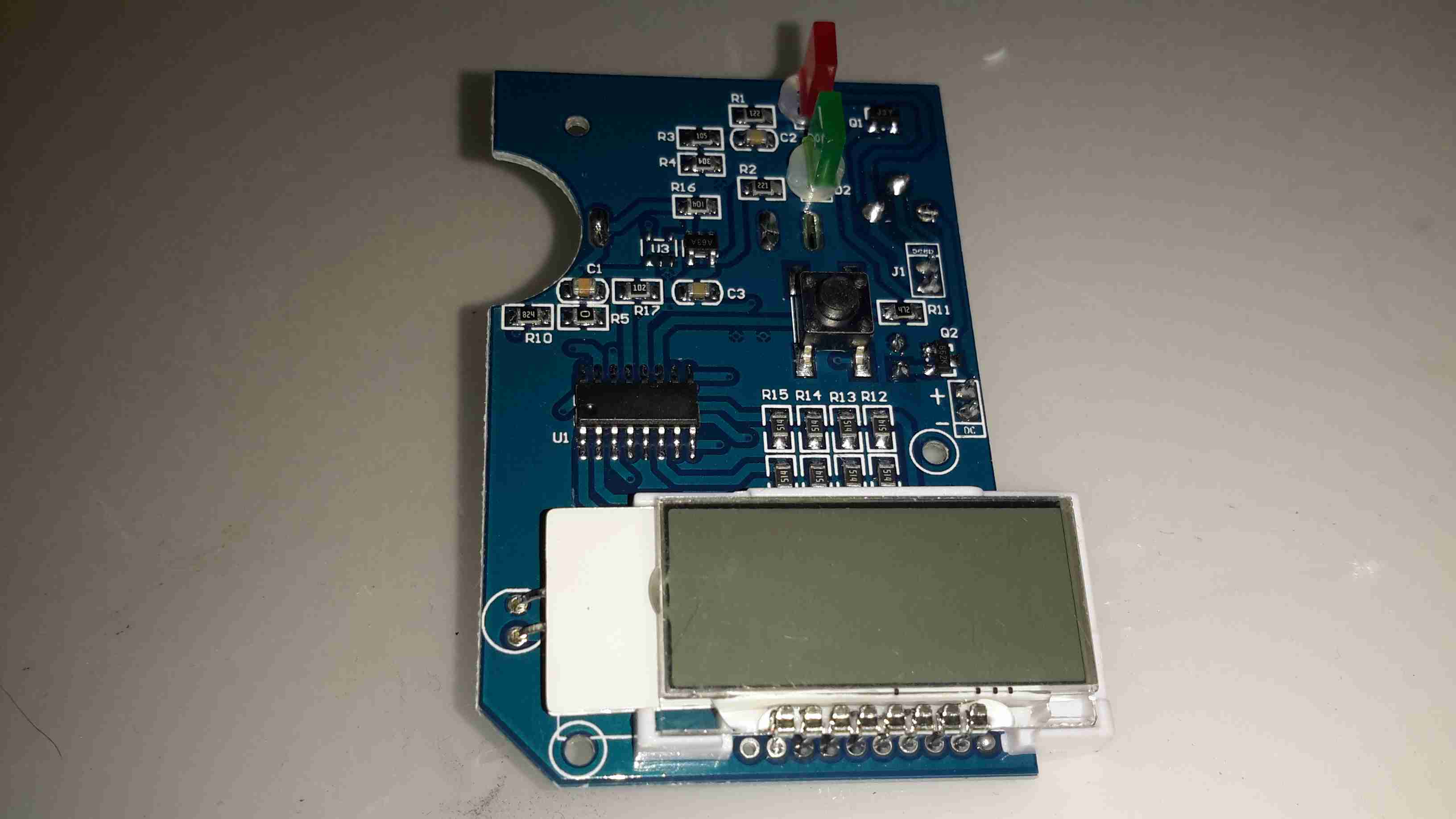
PCB Top
The top of the single sided PCB has the transformer for driving the Piezo sounder, the LEDs & the test button.
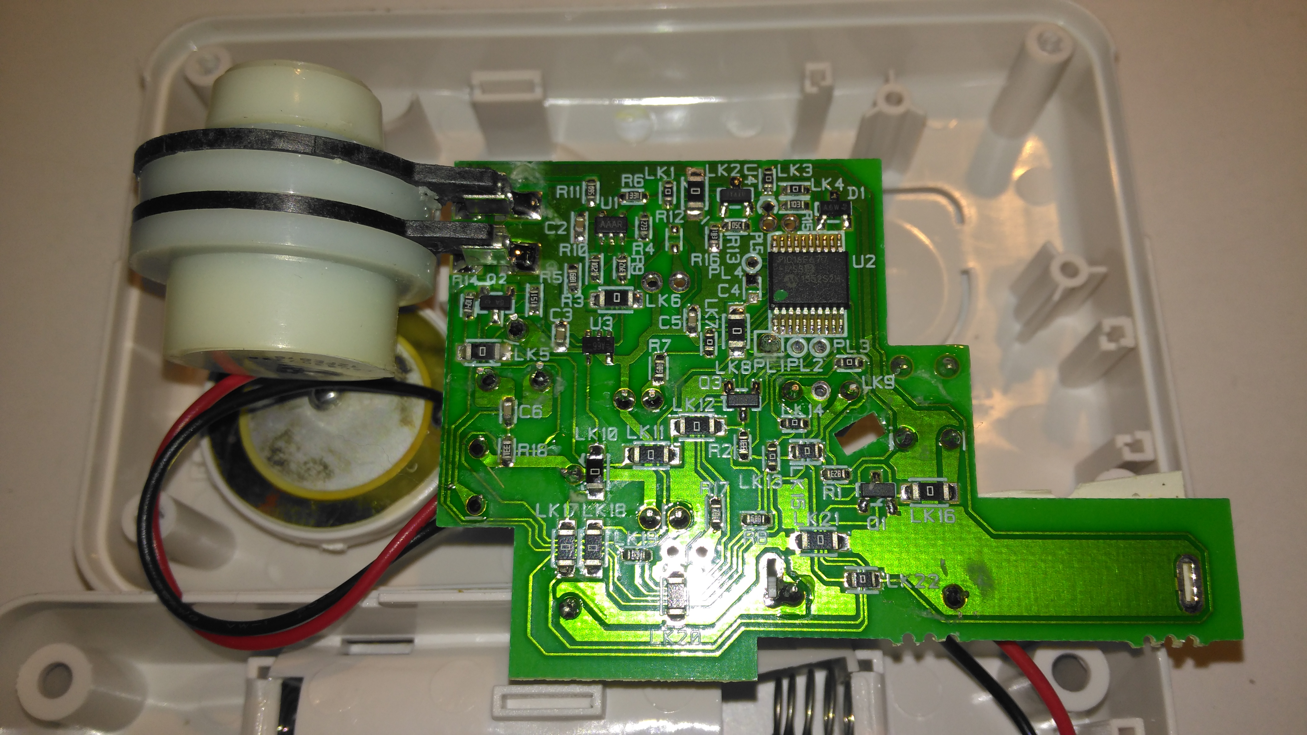
PCB Bottom
All the magic happens on the bottom of the PCB. The controlling microcontroller is on the top right, with the sensor front end on the top left.
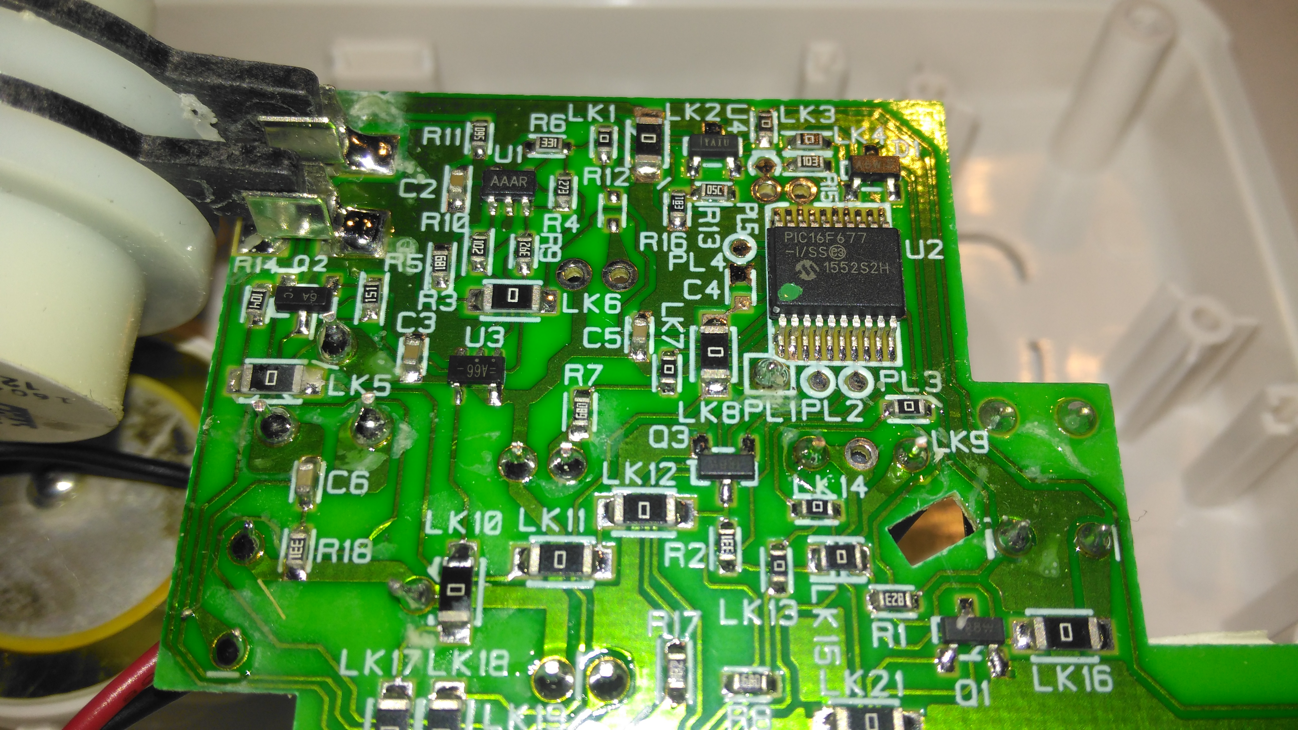
Circuitry Closeup
The microcontroller used here is a Microchip PIC16F677. I’ve not managed to find datasheets for the front end components, but these will just be a low-noise op-amp & it’s ancillaries. There will also be a reference voltage regulator. The terminals on these sensors are made of conductive plastic, probably loaded with carbon.
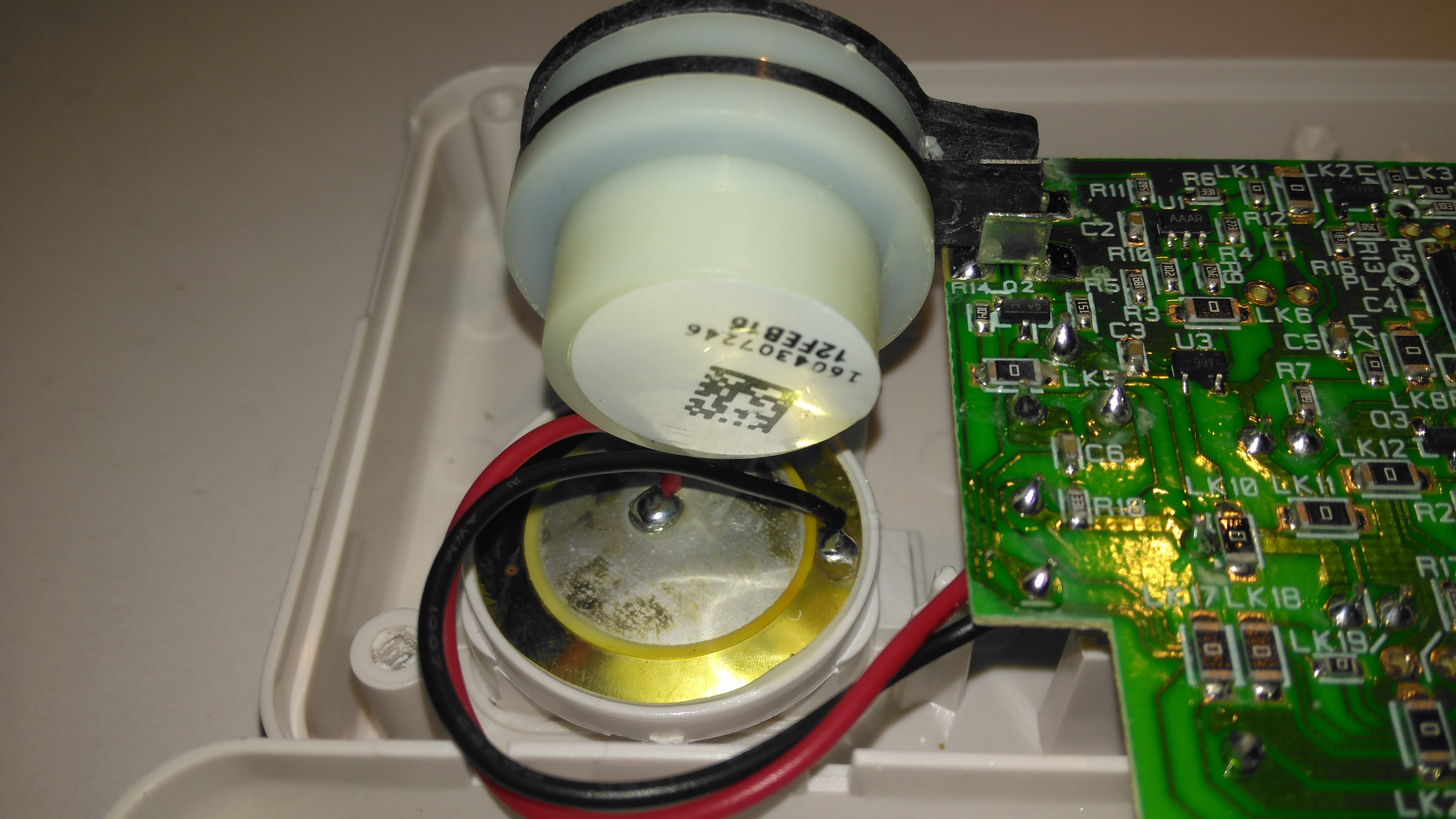
Sensor Cell & Piezo Disc
The expiry date is handily on a label on the back of the sensor, the Piezo sounder is just underneath in it’s sound chamber.
The rear has the specifications, laser-marked into the plastic. The serial numbers are just sticky labels though, and will come off easily with use.
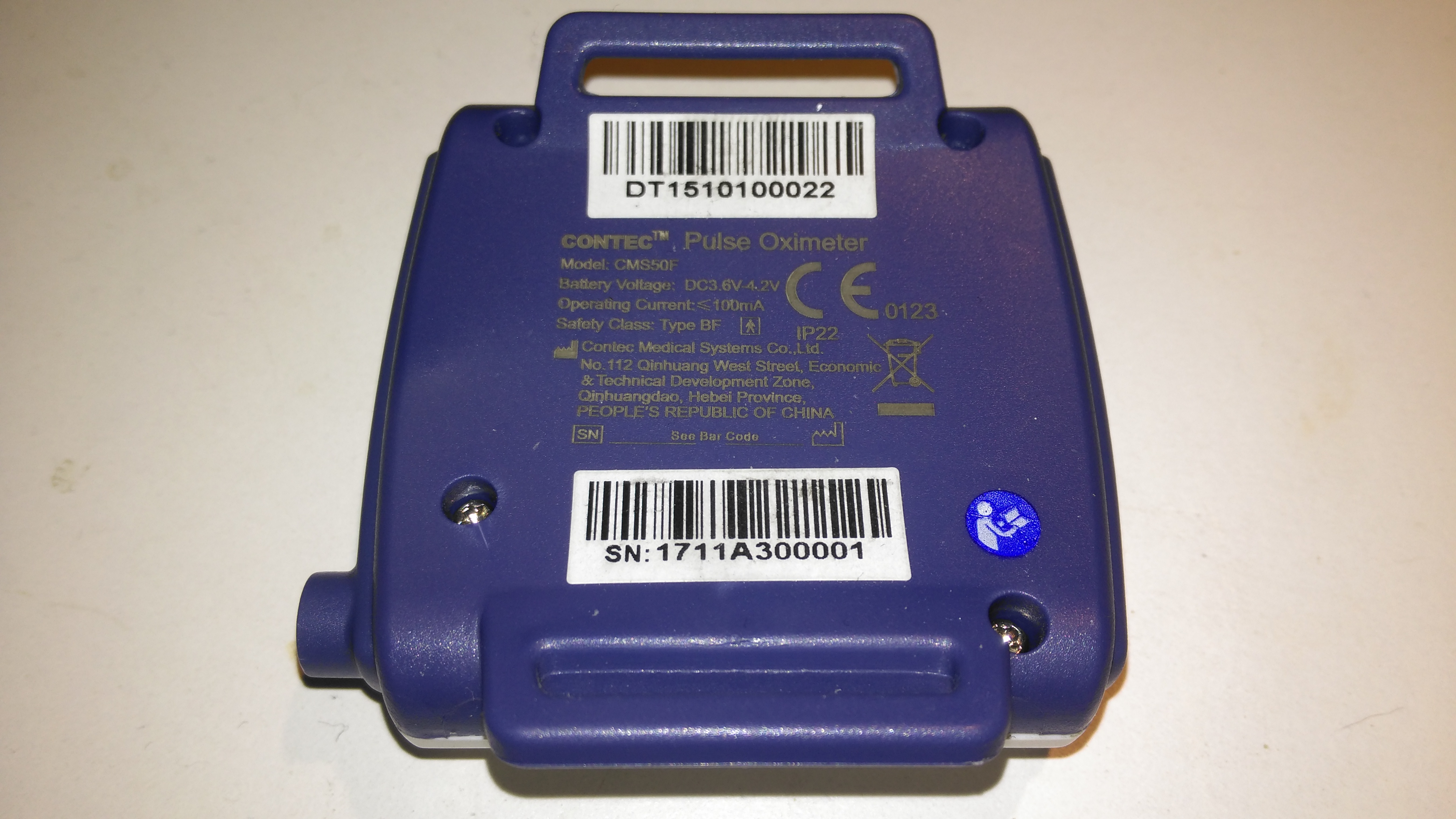
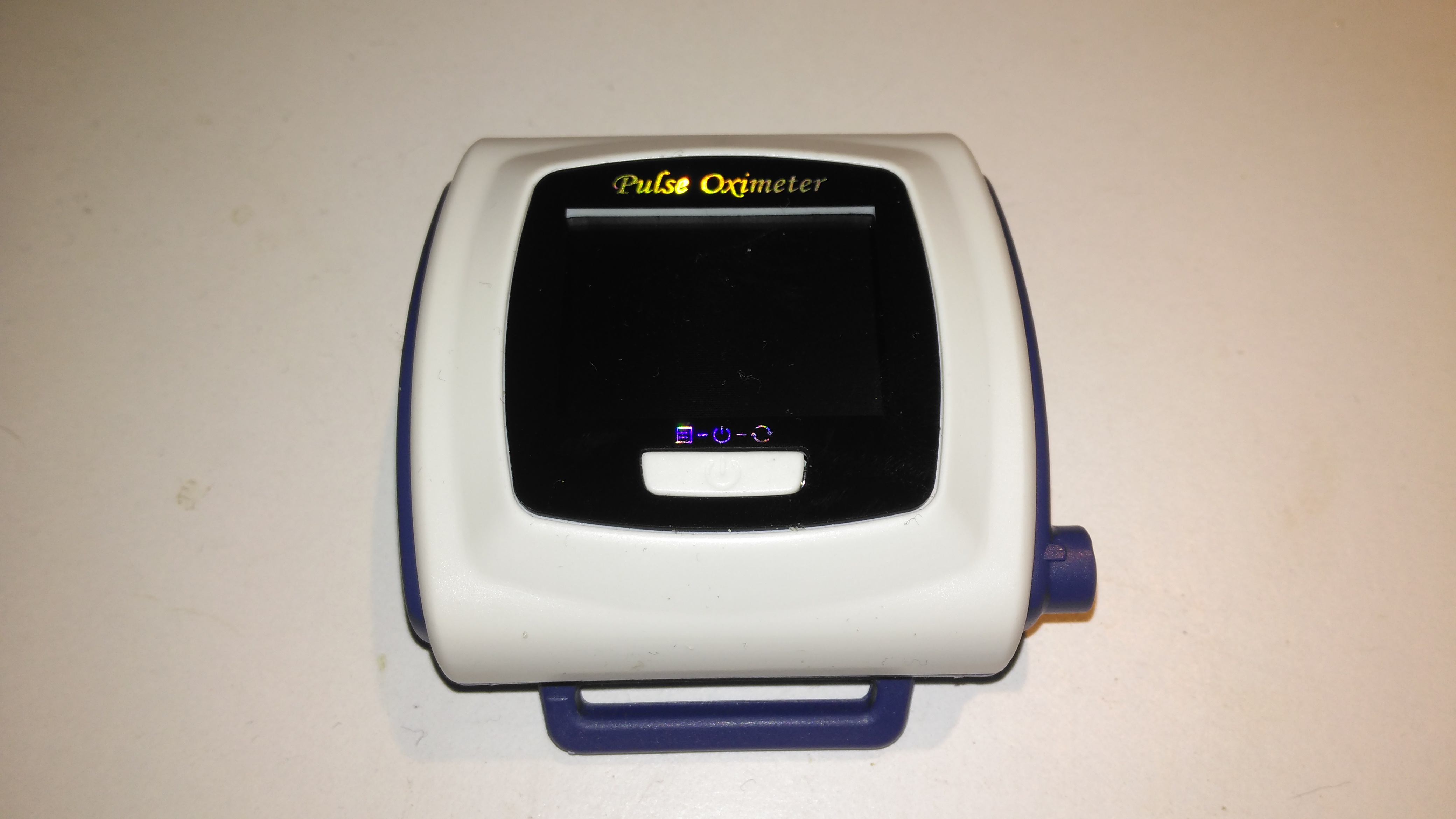
Contec CMS-50F
This is the Contec CMS-50F wrist-mounted pulse oximeter unit, which has the capability to record data continuously to onboard memory, to be read out at a later time via a USB-Serial link. There is software supplied with the unit for this purpose, although it suffers from the usual Chinese quality problems. The hardware of this unit is rather well made, the firmware has some niggles but is otherwise fully functional, however the PC software looks completely rushed, is of low quality & just has enough functionality to kind-of pass as usable.
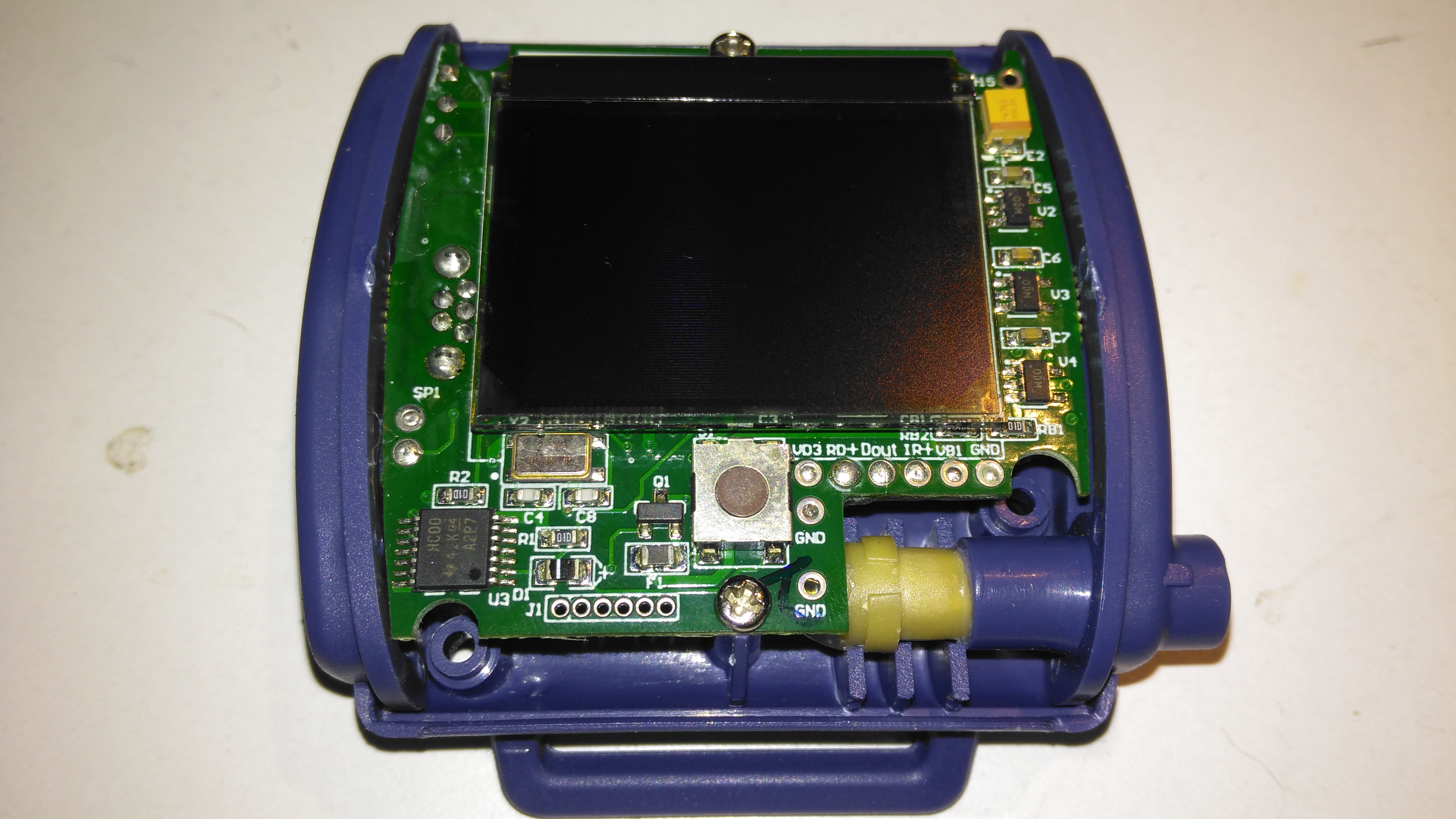
Top Cover Removed
A total of 4 screws hold the casing together, once these are removed the top comes off. The large colour OLED display covers nearly all of the board here. The single button below is the user interface. The connection to the probe is made via the Lemo-style connector on the lower right.
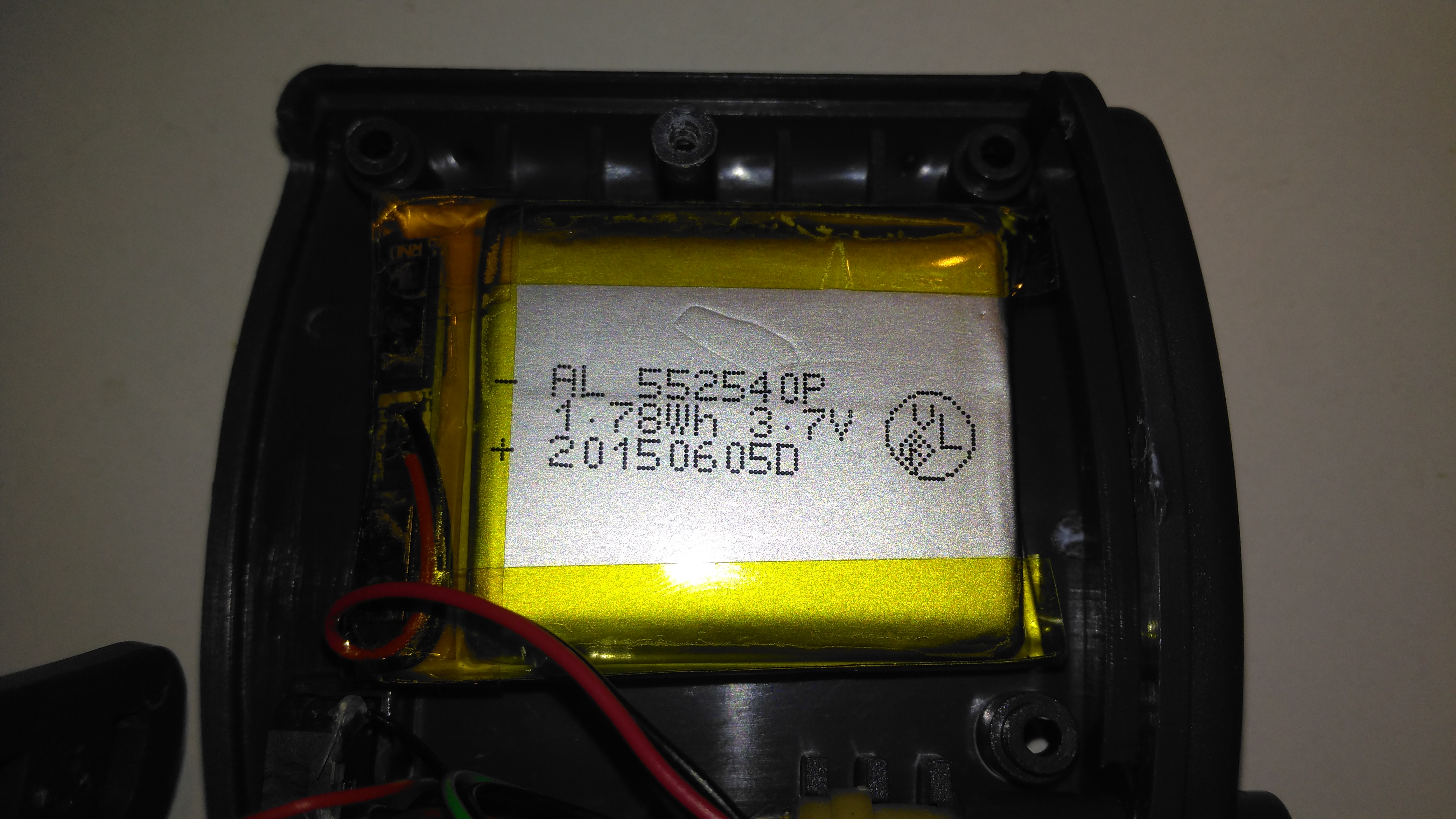
Lithium Cell
Power is provided by a relatively large lithium-ion cell, rated at 1.78Wh.
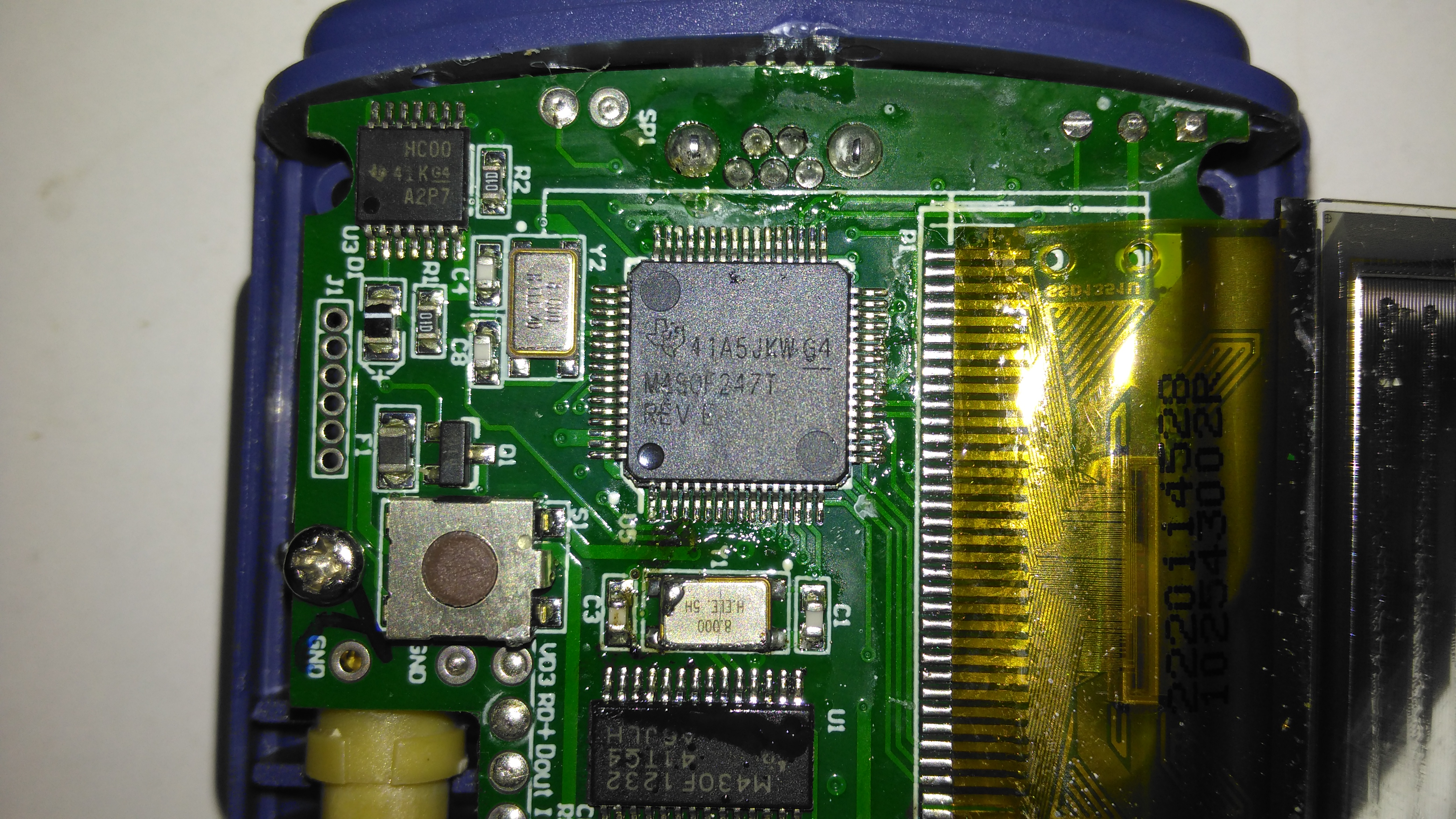
Main Processor
All the heavy lifting work of the LCD, serial comms, etc are handled by this large Texas Instruments microcontroller, a MSP430F247. The clock crystal is just to the left, with the programming pins. I’m not sure of the purpose of the small IC in the top left corner, I couldn’t find any reference to the markings.
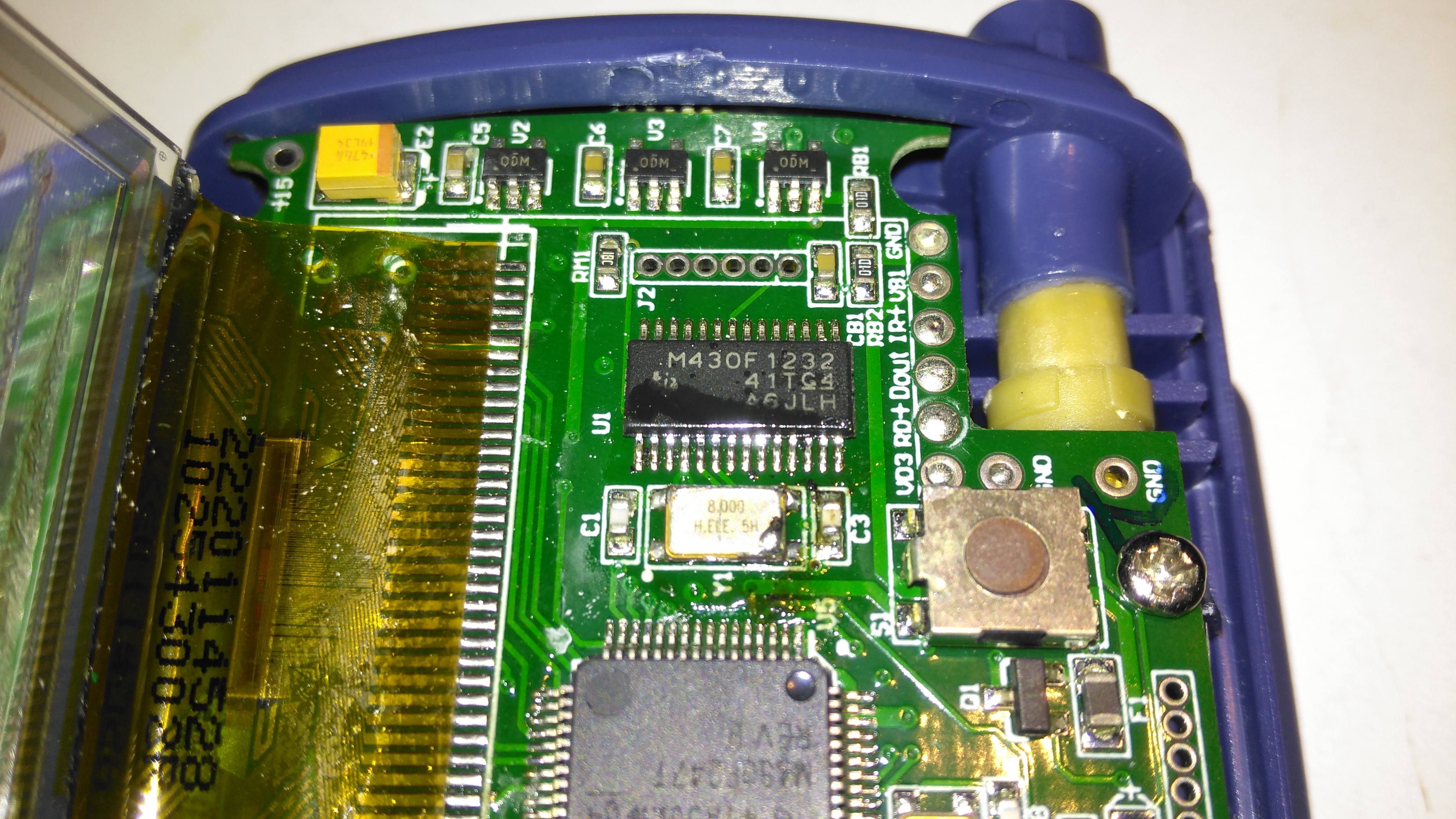
Aux Processor
The actual pulse oximetry sensor readings seem to be dealth with by a secondary microcontroller, a Texas Instruments M430F1232 Mixed-Signal micro. This has it’s own clock crystal just underneath. The connections to the probe socket are to the right of this µC, while the programming bus is broken out to vias just above. The final devices on this side of the board are 3 linear regulators, supplying the rails to run all the logic in this device.
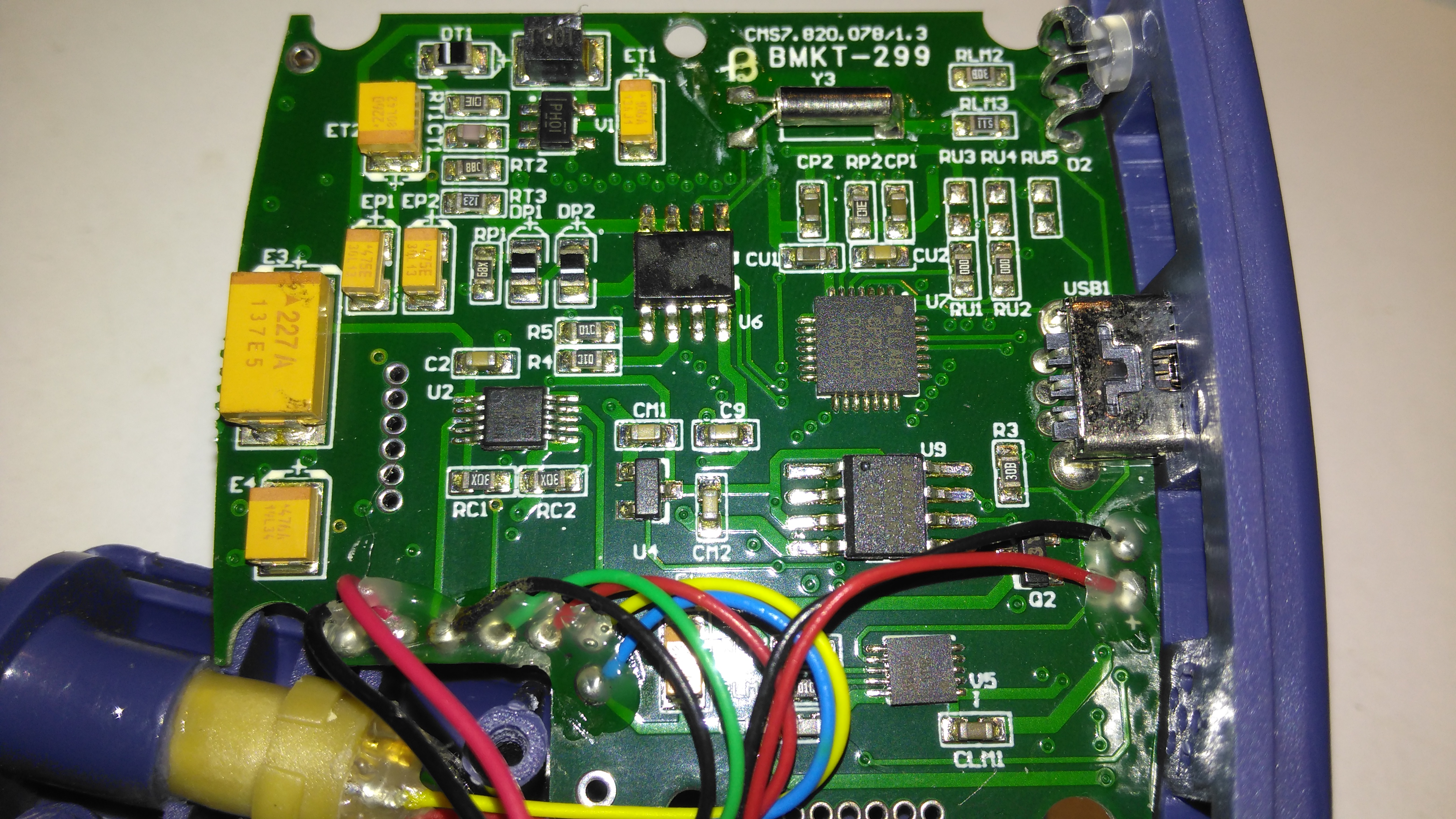
Main PCB Rear
The rear of the PCB has the SiLabs CL2102 USB-Serial interface IC, the large Winbond 25X40CLNIG 512KByte SPI flash for recording oximetry data, and some of the power support components. The RTC crystal is also located here at the top of the board. Up in the top left corner is a Texas Instruments TPS61041 Boost converter, with it’s associated components. This is probably supplying the main voltage for the OLED display module.
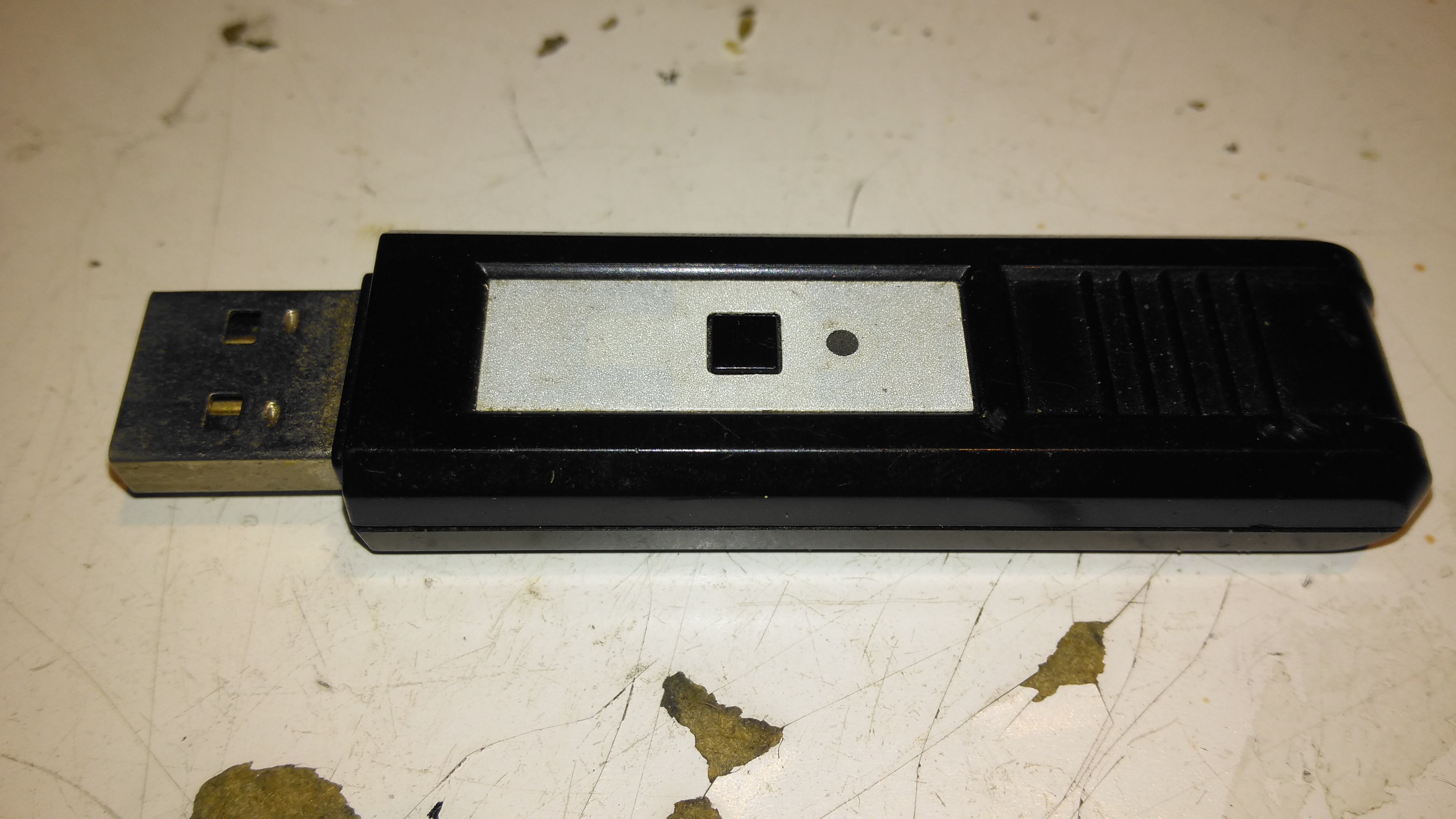
This is a pair of modules that Maplin was selling some time back, to send stereo audio over a 2.4GHz radio link. The transmitter identifies as a USB sound card, I’ve personally used these units to transmit audio about 60ft. The transmitter, above, has a single button for pairing with the receiver below.
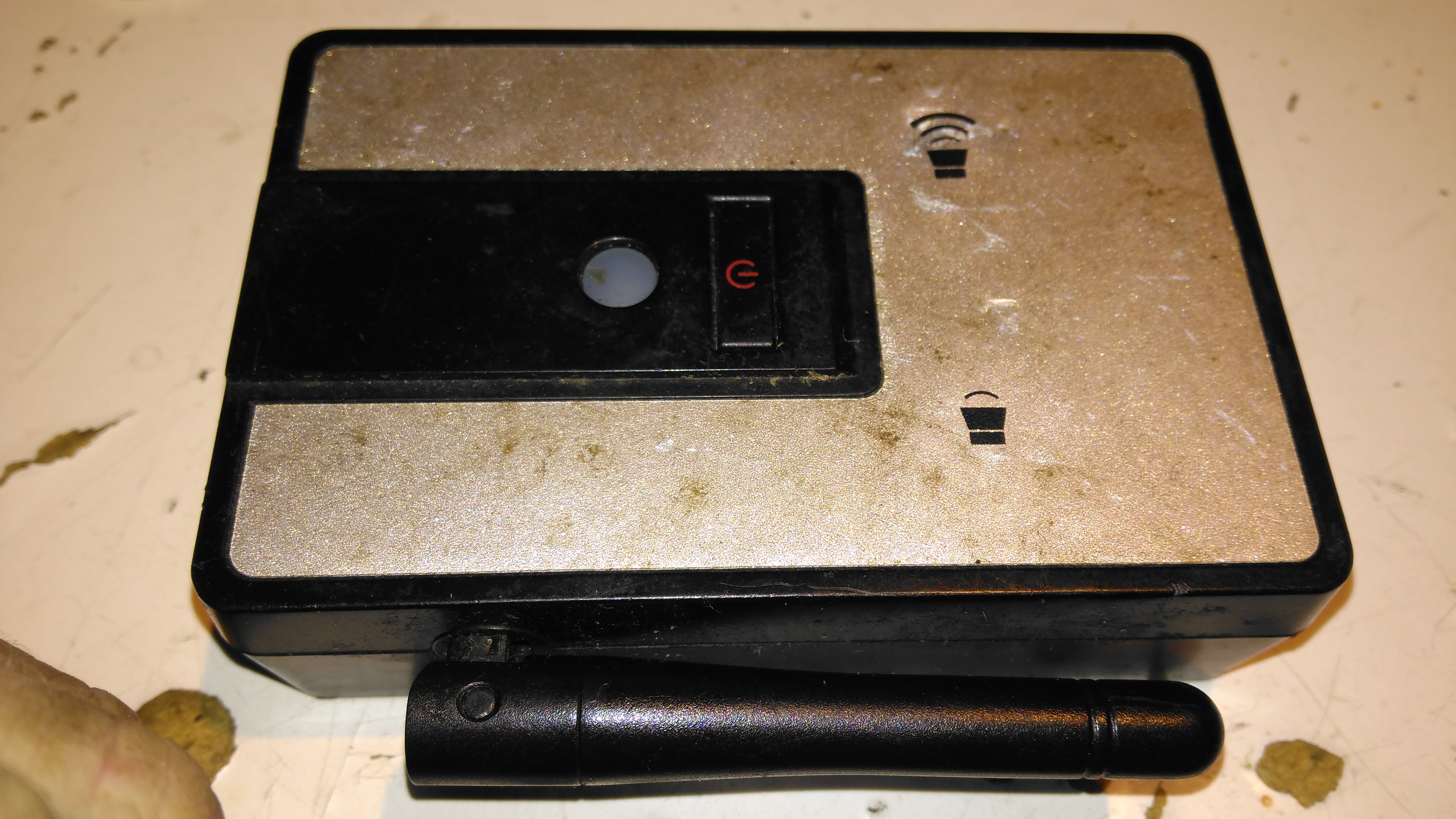
Receiver
The receiver unit has a large external antenna, a link status LED & volume buttons, these directly control the volume level on the host PC via the sound card drivers.
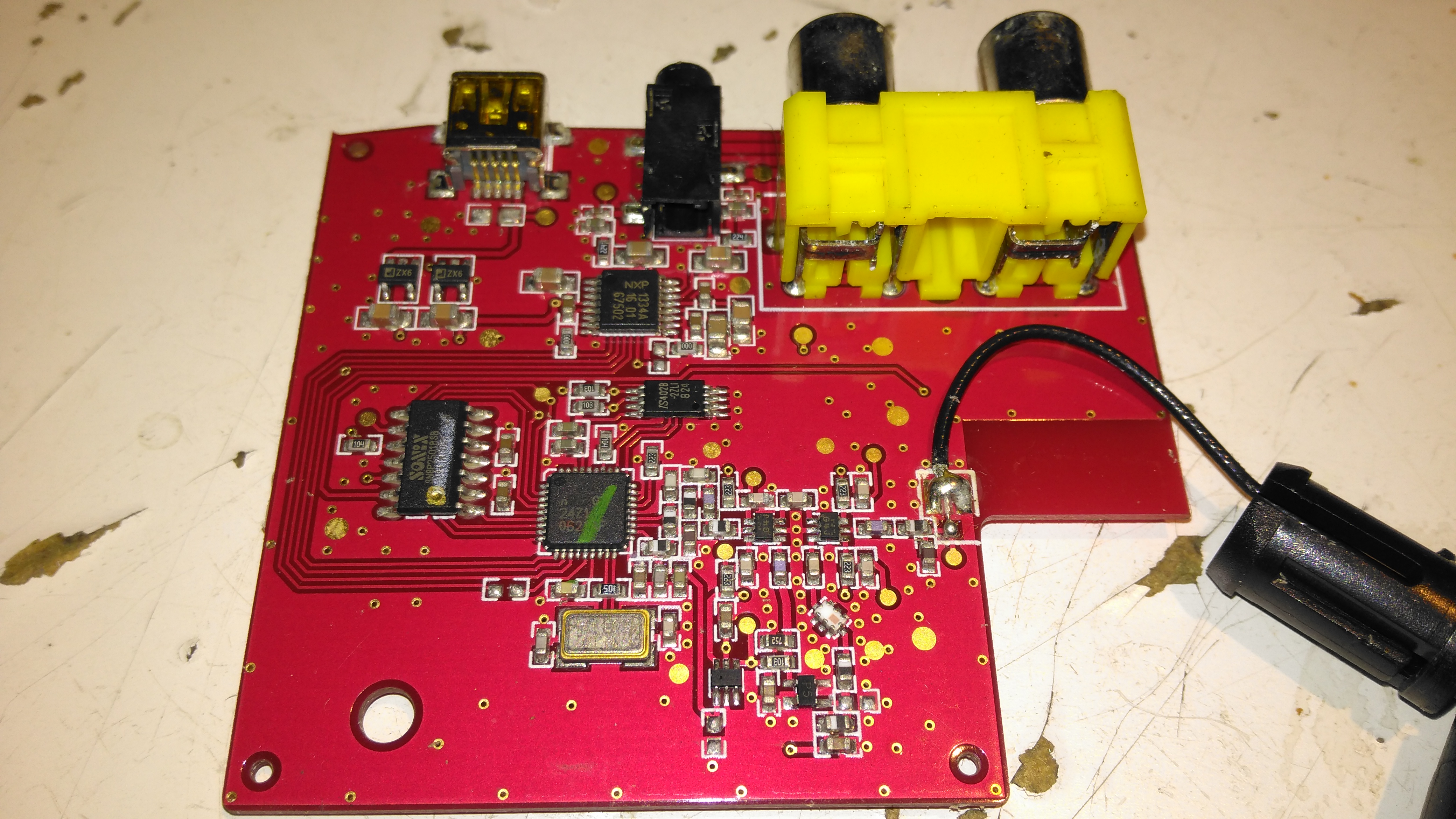
Receiver PCB Top
Popping the case open on the receiver reveals a large PCB, holding the chipset, along with the audio output jacks & Mini-USB power input. The antenna Coax is soldered to the PCB.
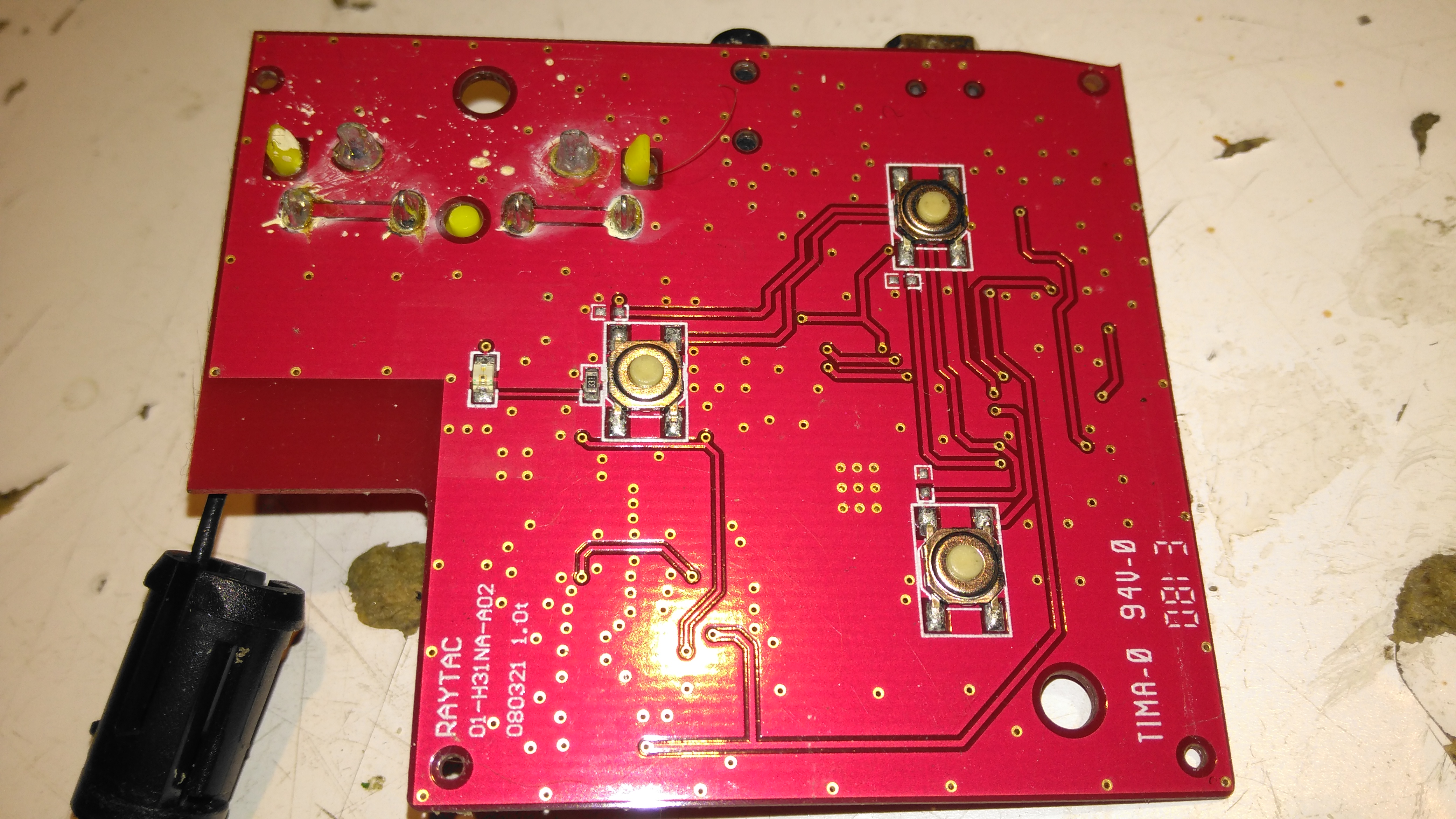
Receiver PCB Bottom
The top of the board has the control buttons, and the status LED.
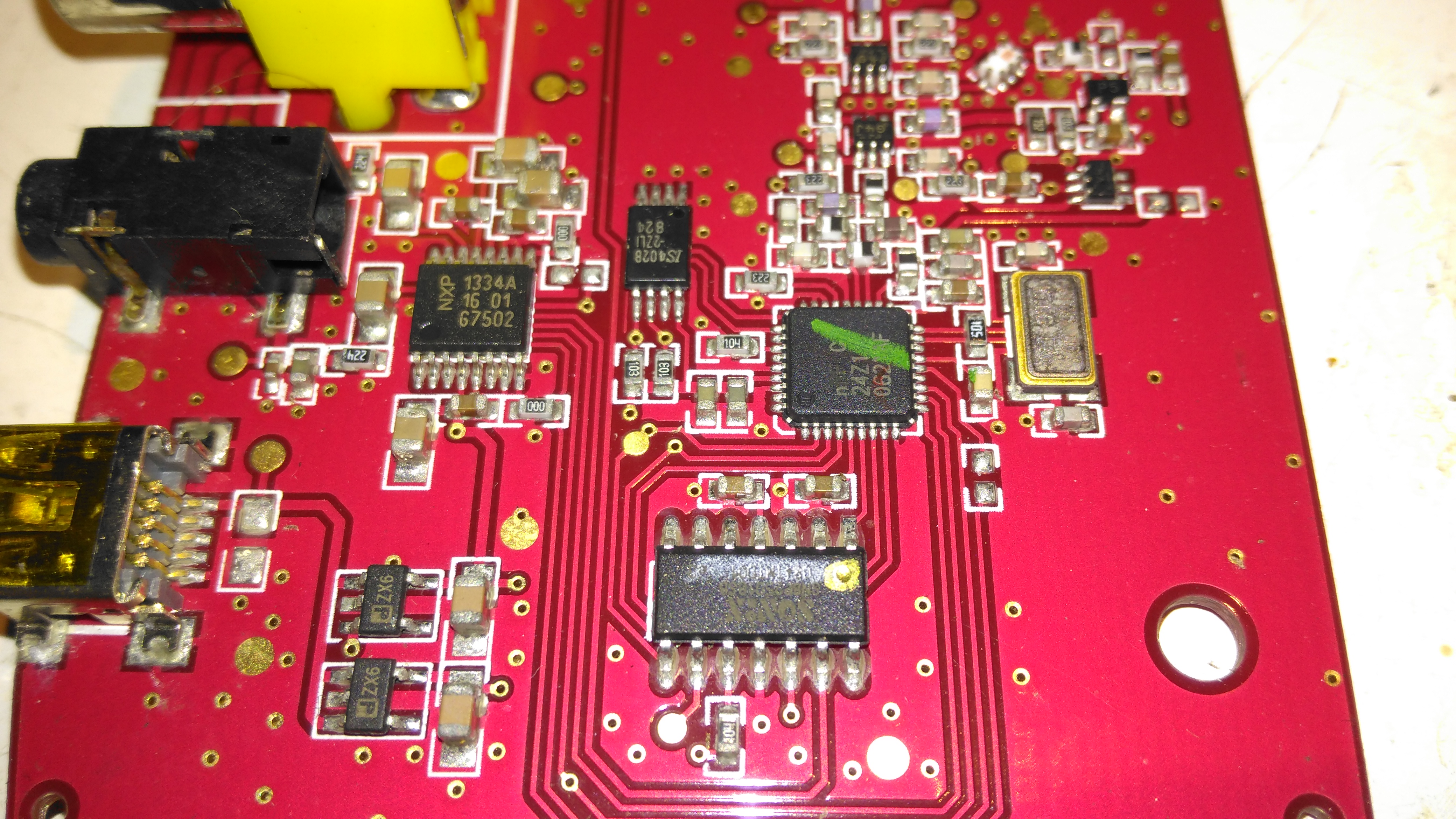
Receiver Chipset
The chipset used here is a Nordic Semiconductor nRF20Z01 2.4GHz Stereo Audio Streamer, there’s a small microcontroller which does all the register magic on the RF transceiver. The RF chain is at the top of the photo, audio outputs on the top left, and the micro USB power input & voltage regulators at bottom left.
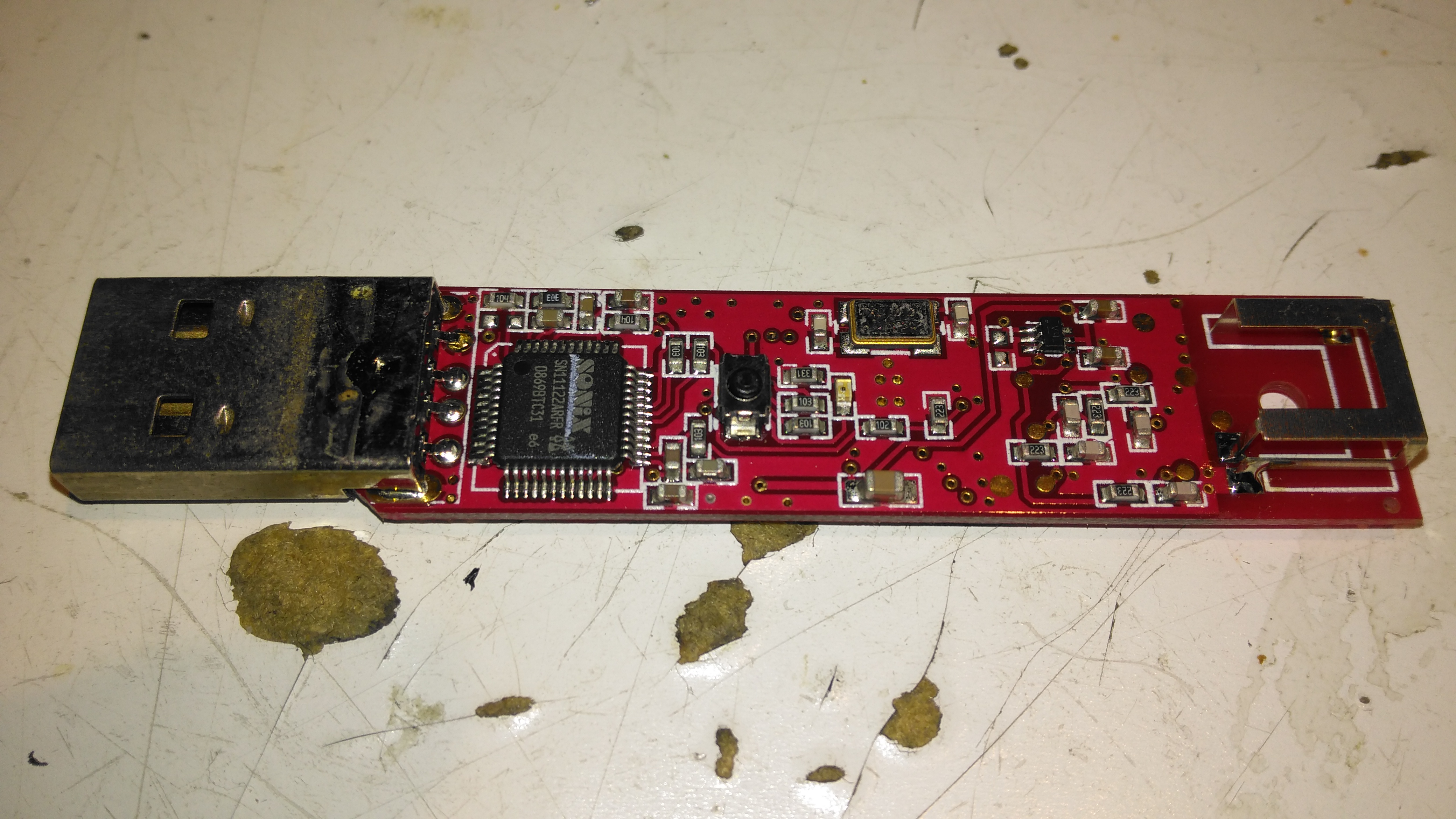
Transmitter PCB Top
The transmitter PCB has a Sonix USB Audio Codec, to interface with the host PC. This is then fed into another Nordic Semi part on the opposite side of the board:
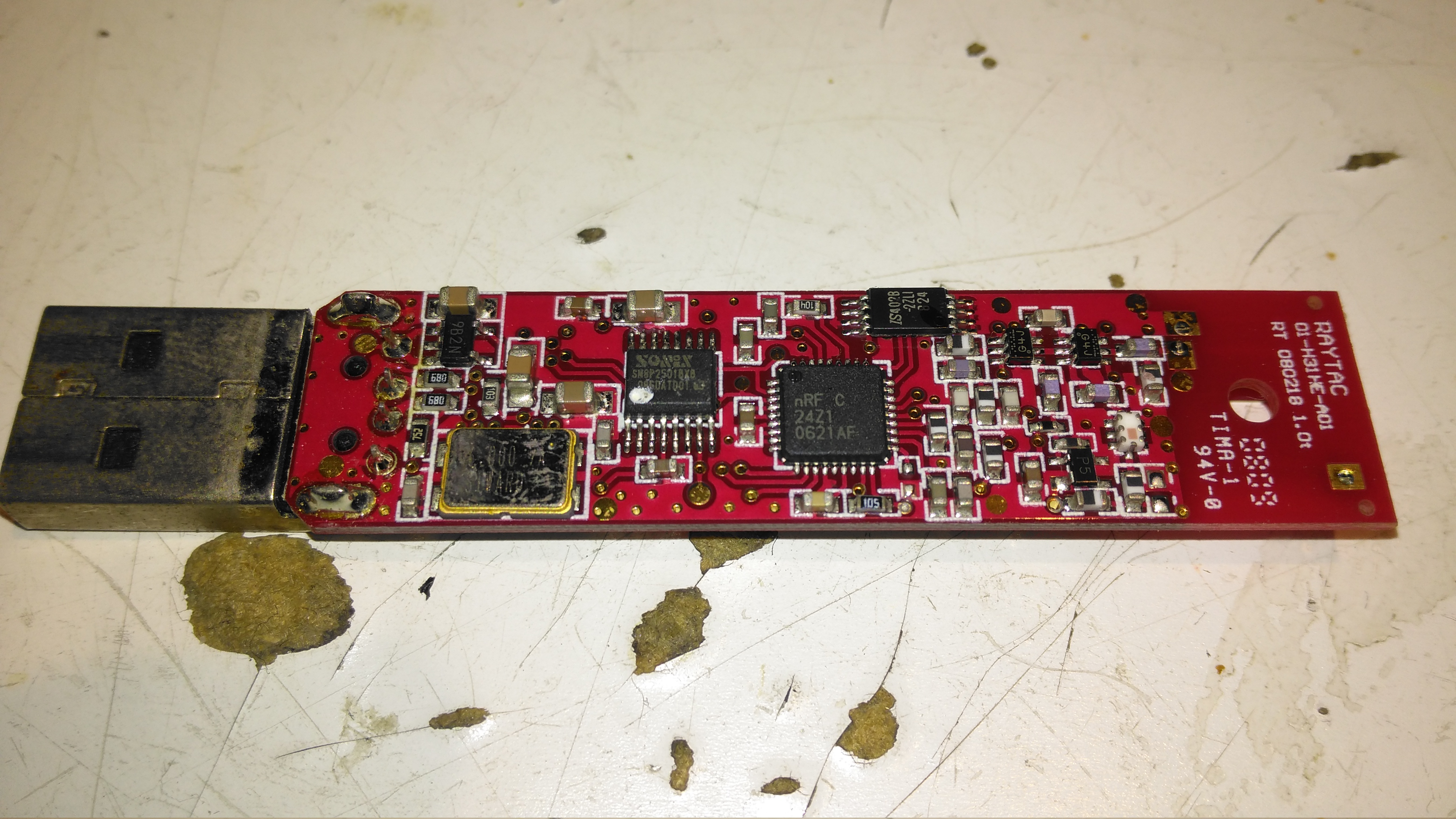
Transmitter PCB Bottom
The bottom of the transmitter has the RF section, and another small control microcontroller.
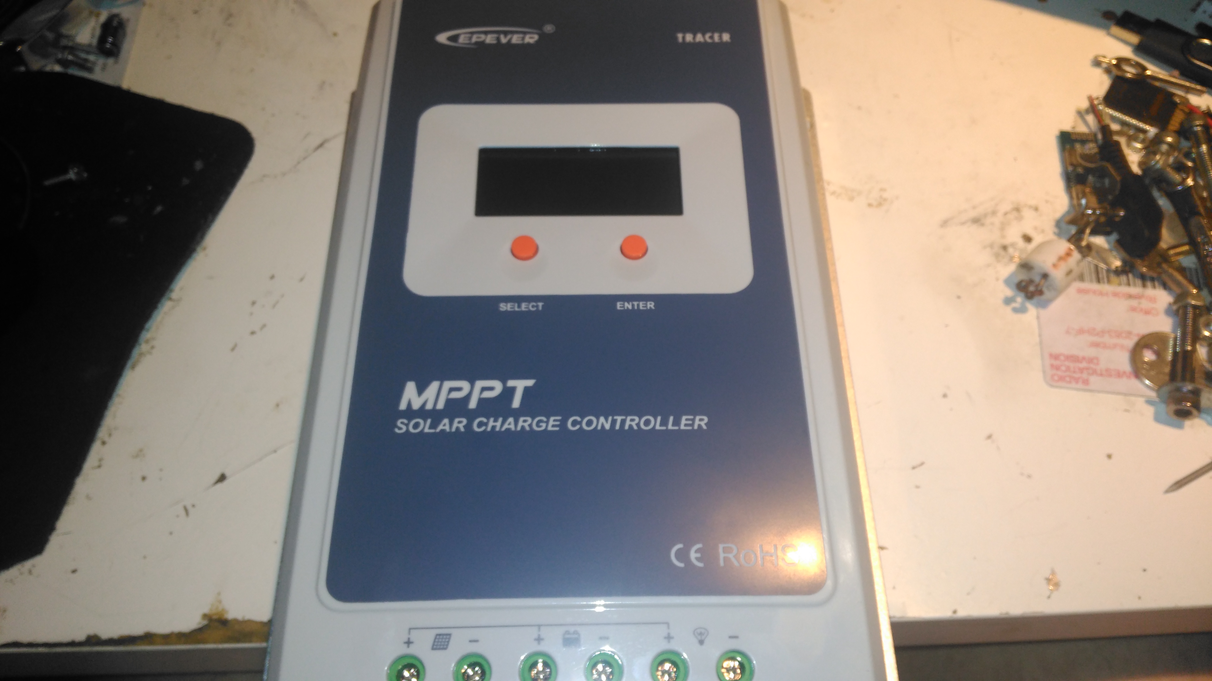
Here’s the solar charge controller to go with the MT50 from the last post. This is the 40A version of the EpEver Tracer A series, the 4210A. This unit is large, and very heavy. Most of this weight comes from the enormous heatsink which doubles as the mounting plate for all the other components, and the large inductors that are going to be required for the DC-DC conversion that MPPT requires.
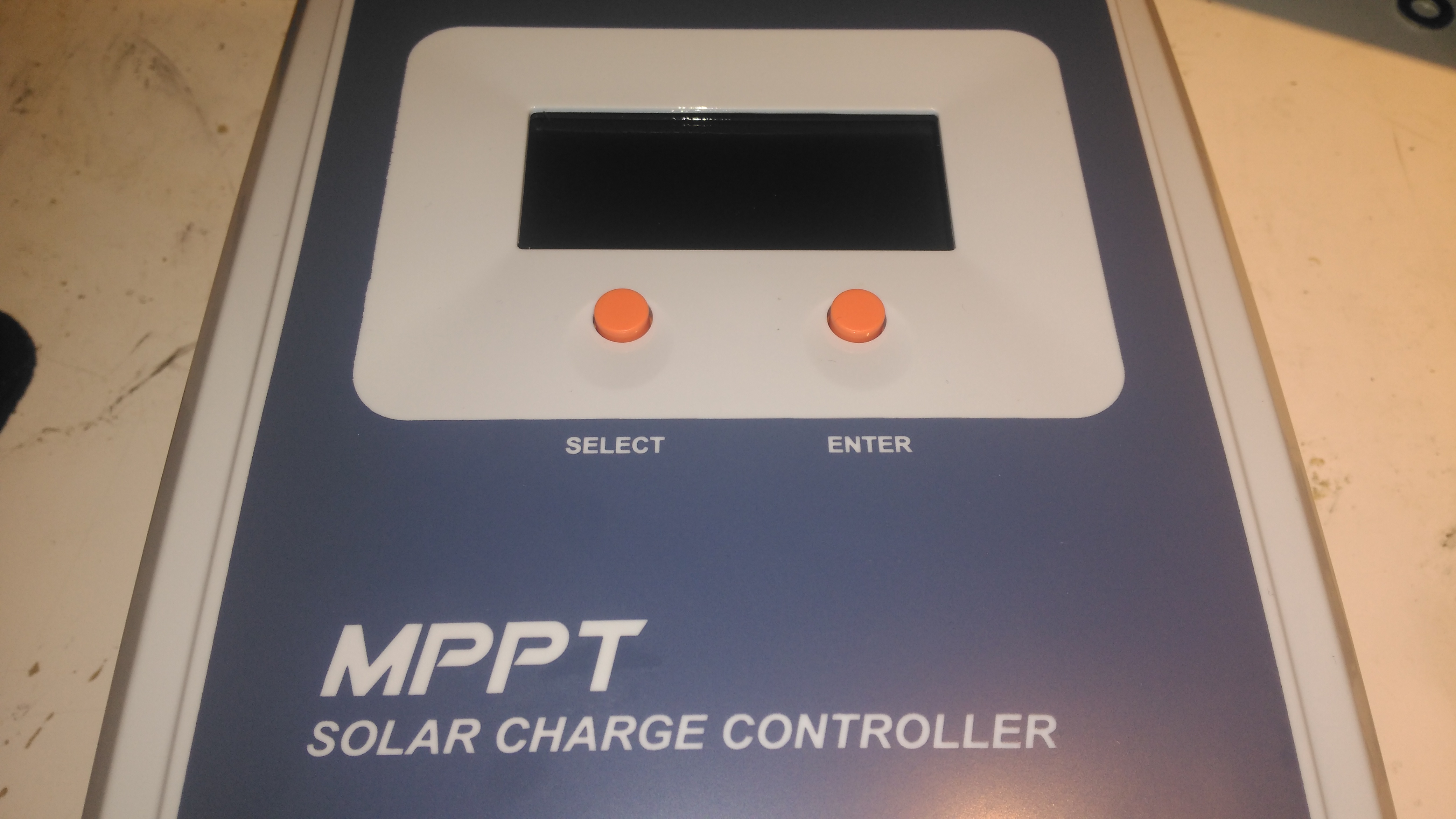
Front Panel
The front panel has a basic LCD, which shows various stats, such as PV Volts & Amps, and battery bank Volts & Amps. The pair of buttons are used to navigate the basic menu to configure some options, along with switching the load terminals ON/OFF.
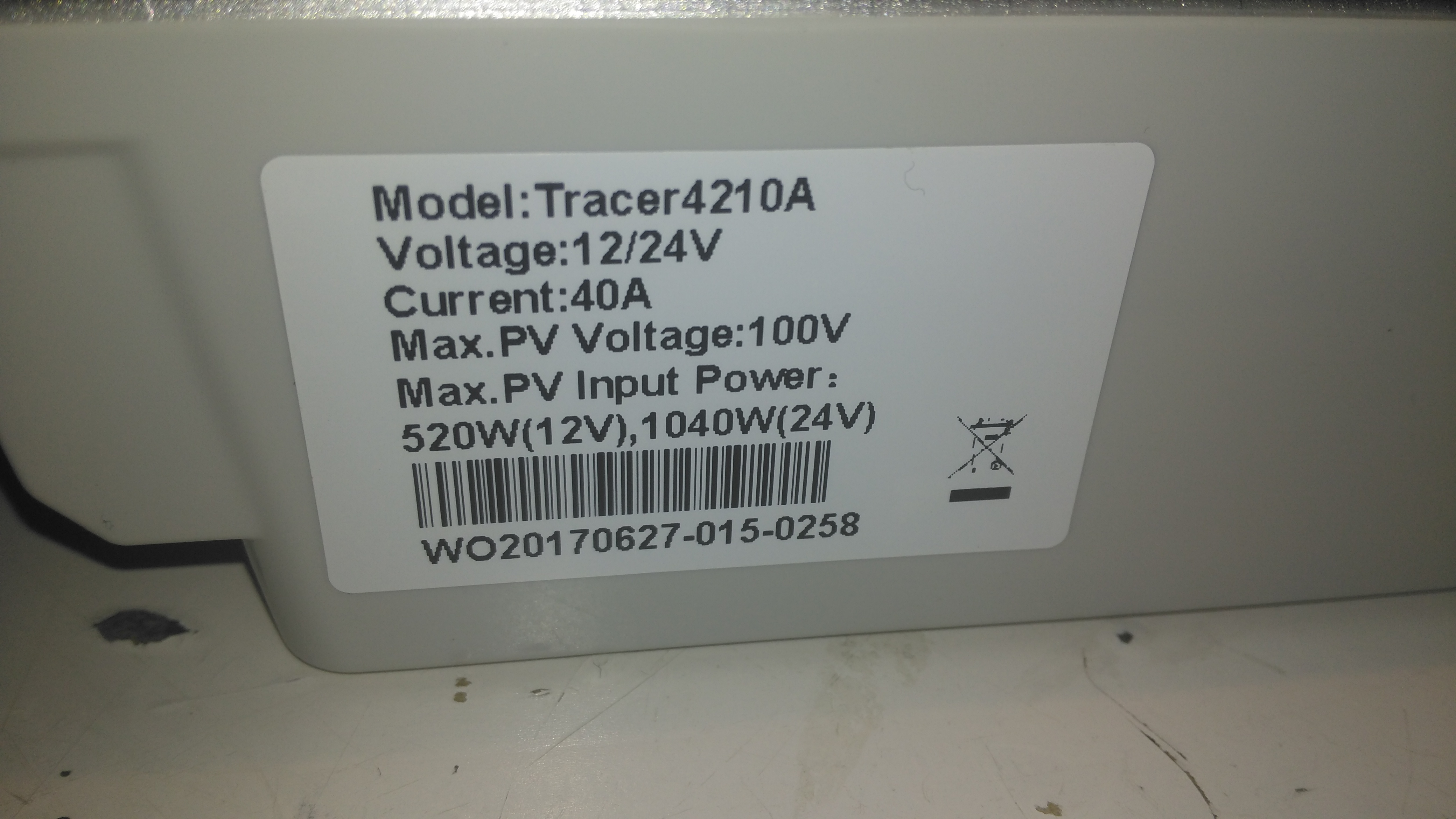
Specifications
There’s a specs label on the top, with a slight difference here vs the manual, which states the max. PV volts as 92v.
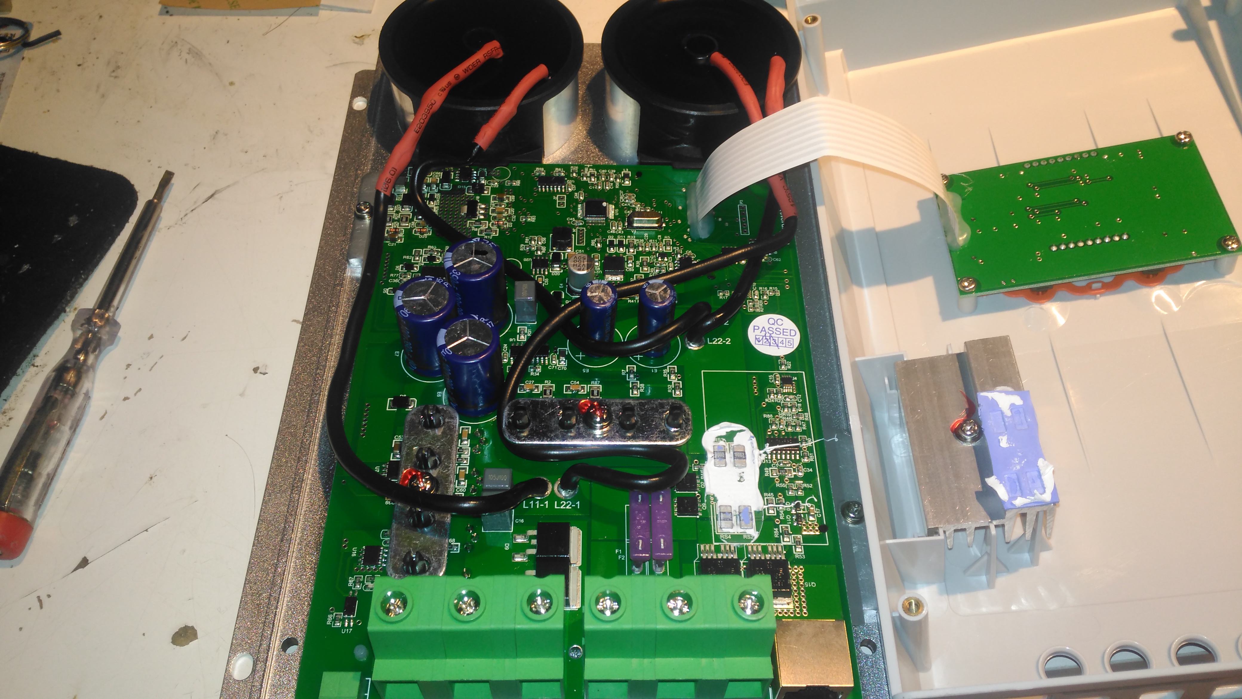
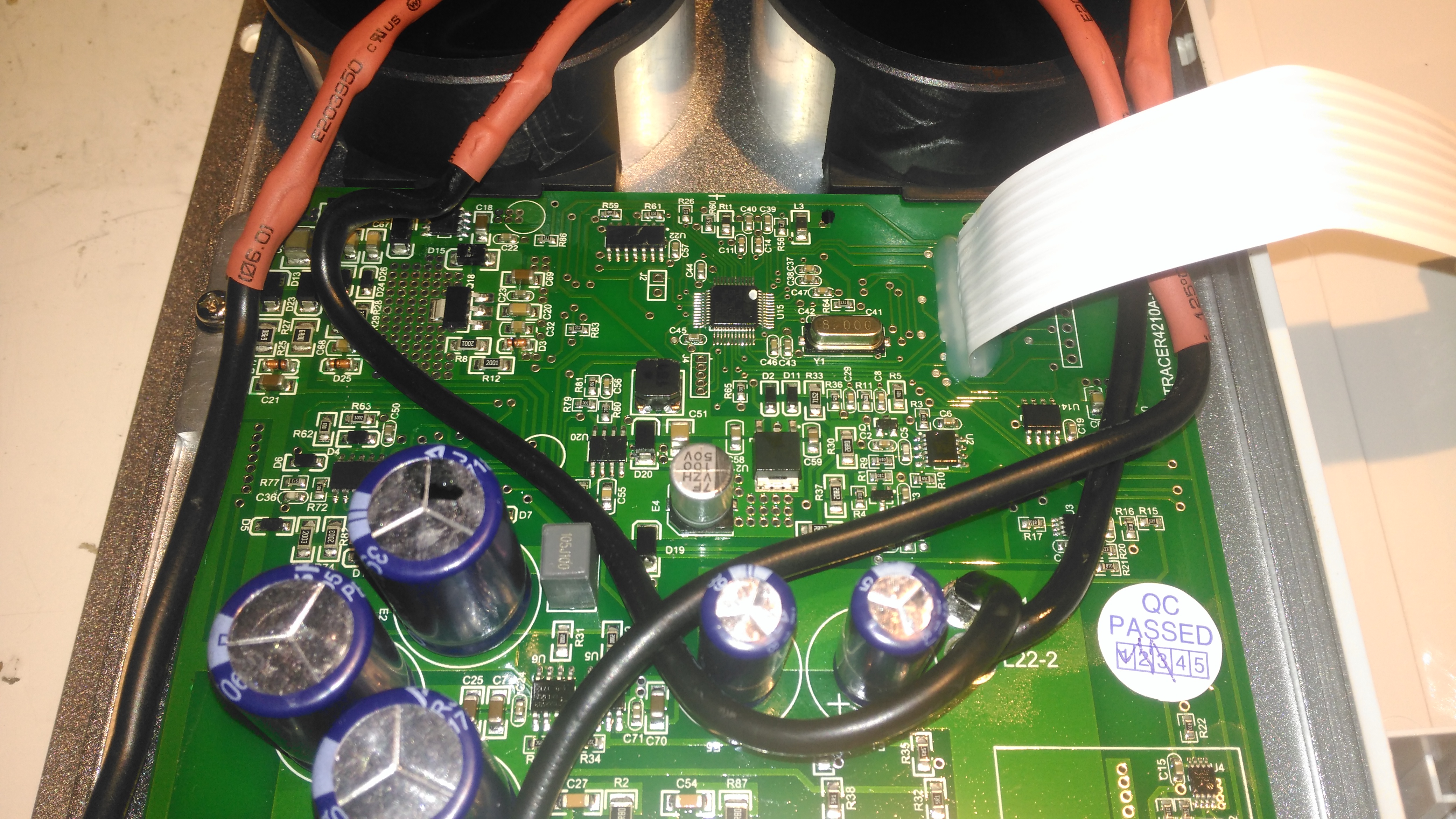
Main PCB Overview
Removing 4 machine screws from the bottom of the unit allows the top to come off. Like the MT50 remote panel, this unit also has moulded-in brass thread inserts in the plastic parts. The PCB in here is heavily comformal coated, which stops me from reading the laser-etched numbers on the semiconductor devices, so there will be few details there.
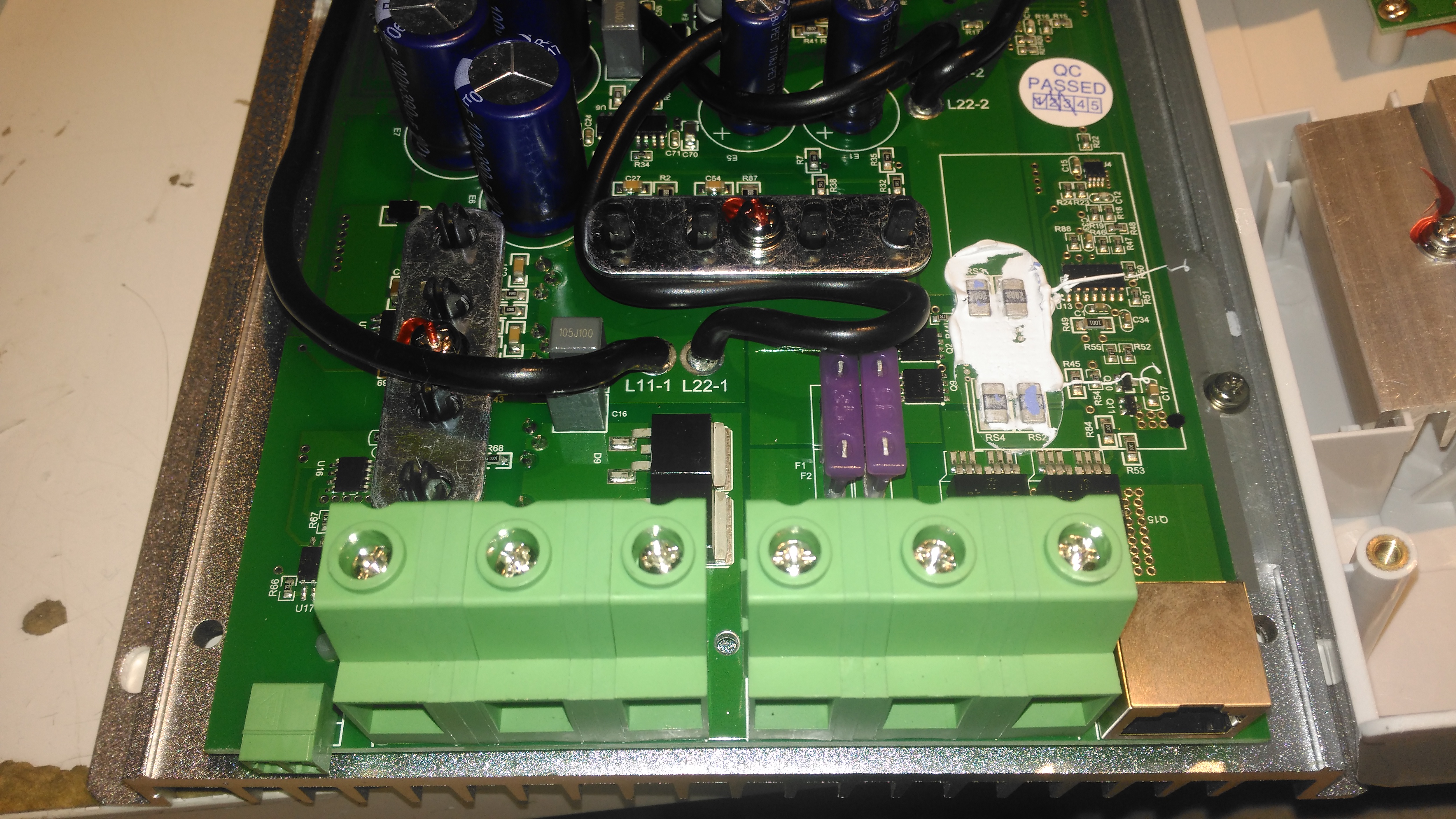
Main PCB Lower
Here’s the bottom section of the main PCB, with the enormous screw terminals, which will easily take cables up to about 16mm². The RJ-45 jack which hosts the unit’s RS-485 bus is to the right, and a smaller 2-pin connector on the left sorts out the battery temperature sensor.
The DC output MOSFET switches are hiding just behind the right-hand terminals, there’s a pair of them in this unit to handle the output current. Some beefy diodes polarity-protect both the battery & PV inputs.
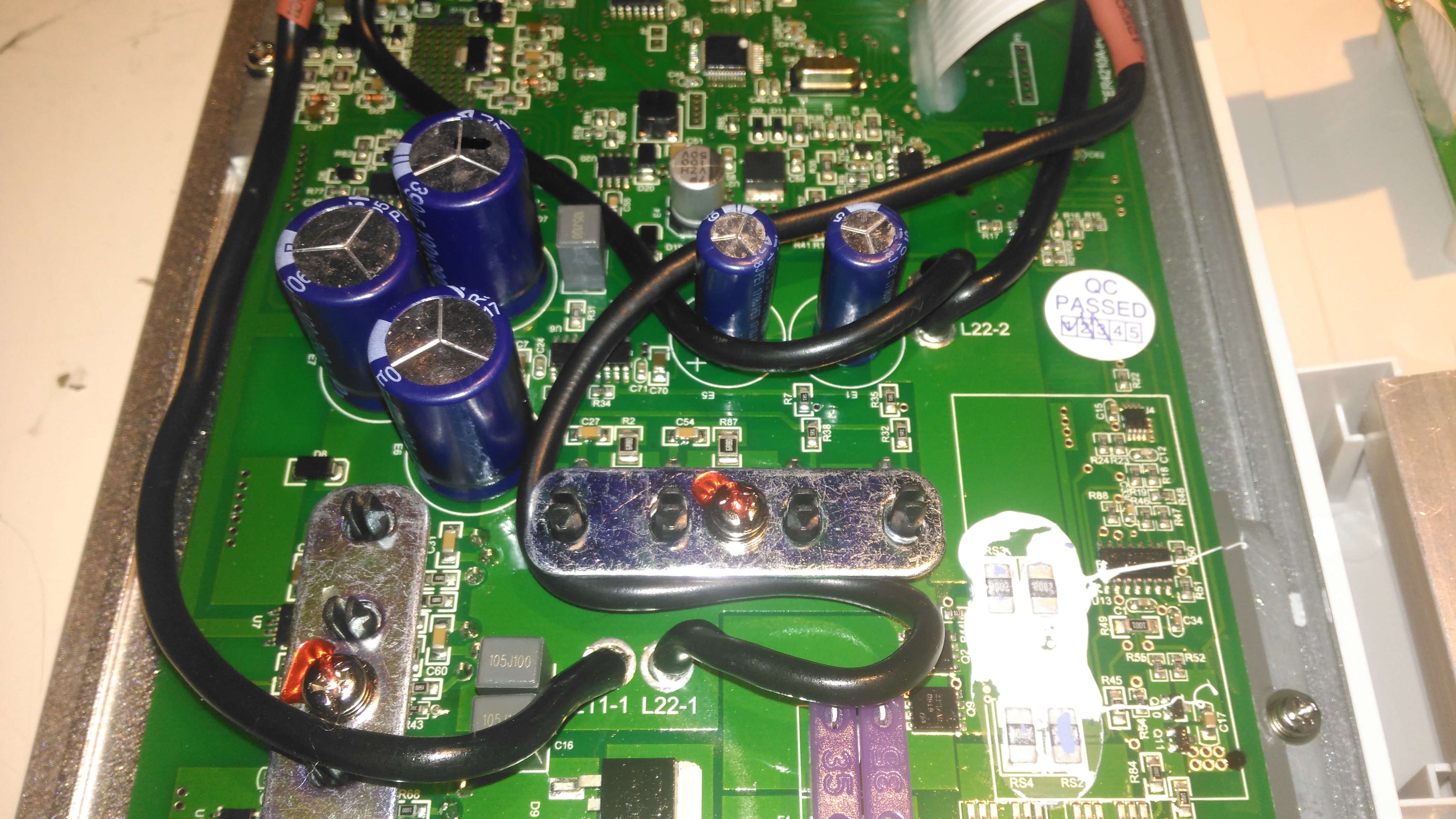
Board Centre
Moving up the board shows two 35A automotive blade fuses soldered into the board – these would be a real pain to replace if they ever blew, however with the electronic load current protection built into this unit, it’s an unlikely situation, unless something went hideously wrong. The main switching devices for the DC-DC converter are hidden – they’re clamped to the heatsink with the bars at right angles in the photo, I’m not going to dig any deeper into this just for those though – they’re just TO220 devices.
Under a load of thermal gunk on the right are 4 current shunt resistors, and the amplifiers for reading their values. These 1206-size SMD resistors looked a bit small for the power rating to me, but they’re heatsinked in operation to a small heatsink mounted in the top cover.
Board Upper
The upper section of the PCB hosts the main microcontroller, and the connections over to the front panel LCD & buttons. Couldn’t really get much info from these chips, due to the conformal coating.
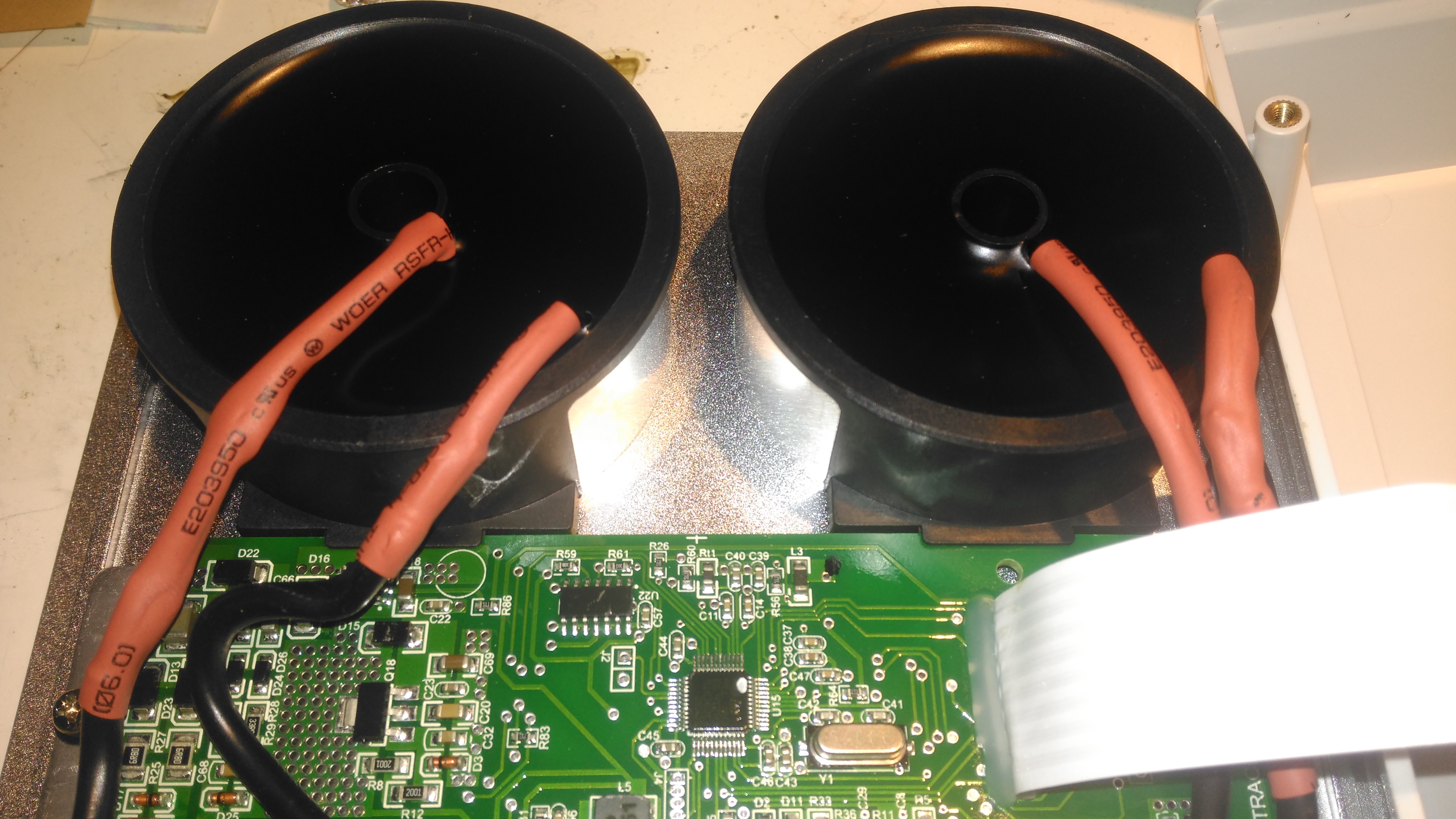
Toroidal Inductors
Right at the top of the unit are these toroidal inductors, potted into aluminium housings. The copper windings of these is very heavy – at least 2.5mm². They’re electrically in parallel, the 20A version would only have a single inductor.
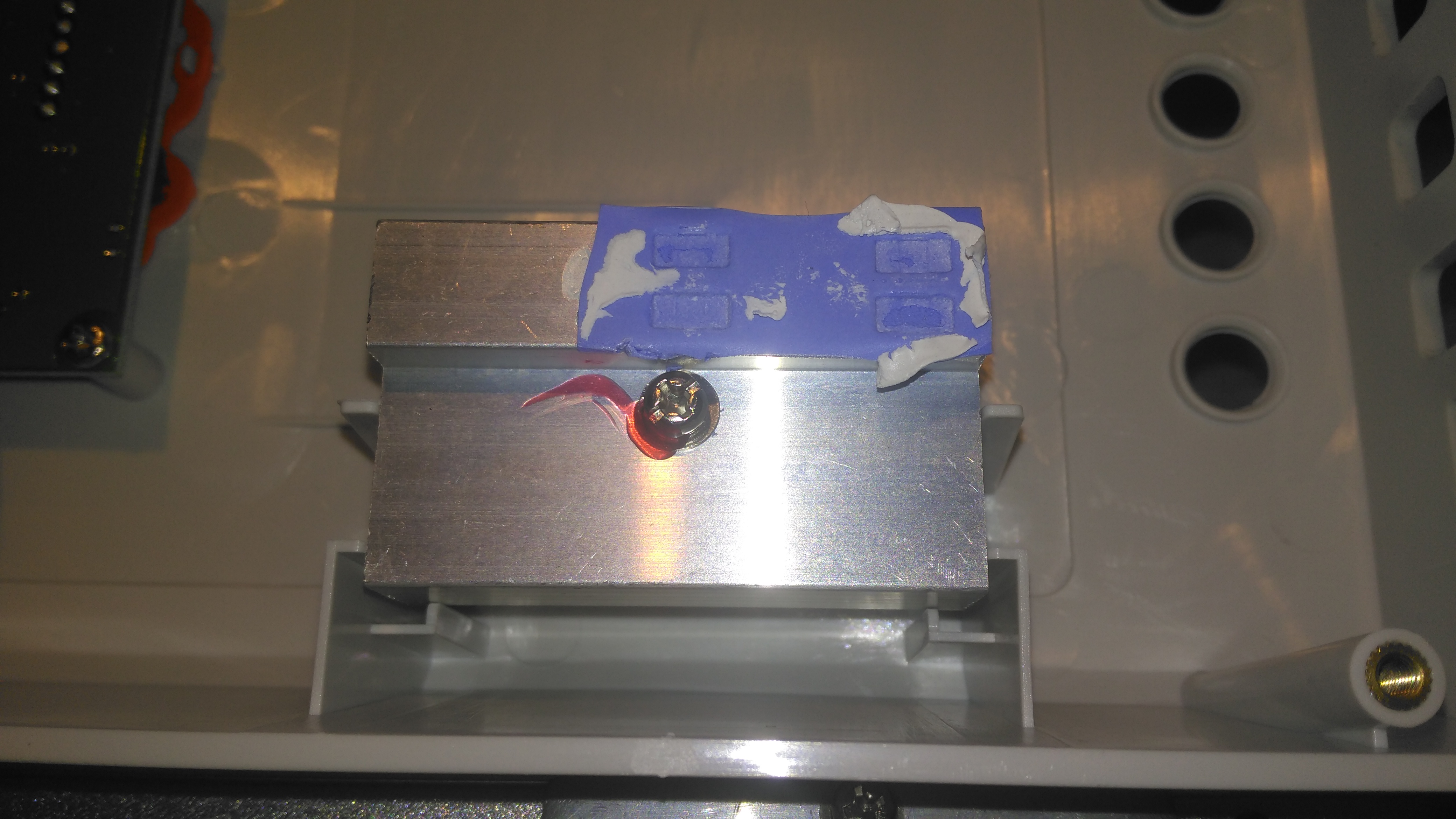
Current Shunt Heatsink
This small heatsink sits inside the top cover, and provides some cooling to the current shunts.
Display Board
Not much to say for the display board, there’s going to be nothing here apart from an I²C LCD driver & the pair of front panel buttons, so I won’t bother removing this from the case.
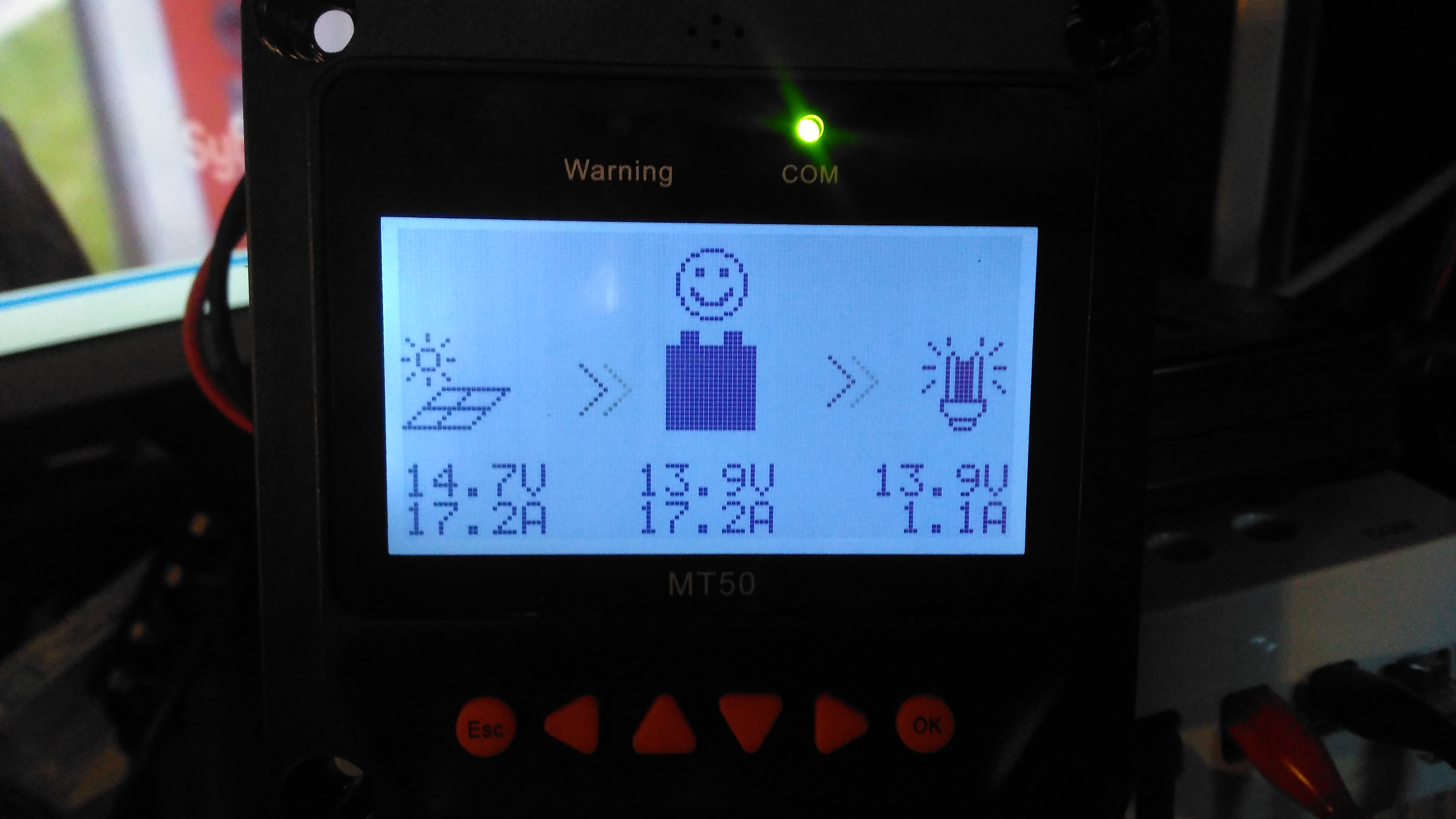
Here’s the MT50 controller from EpEver, that interfaces with it’s Tracer MPPT solar charge controllers, and gives access to more programming options on the charge controllers, without the need for a laptop. The display is a large dot-matrix unit, with built in backlight. Above is the display on the default page, showing power information for the entire system.
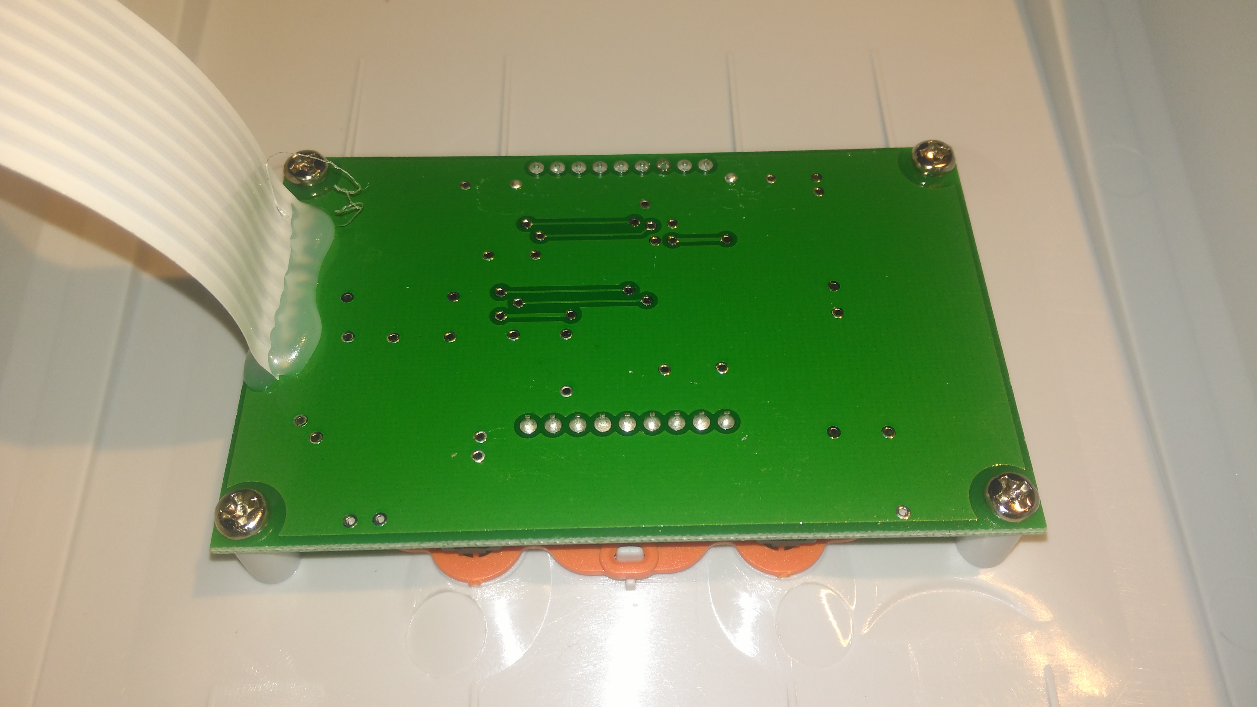
PCB Rear
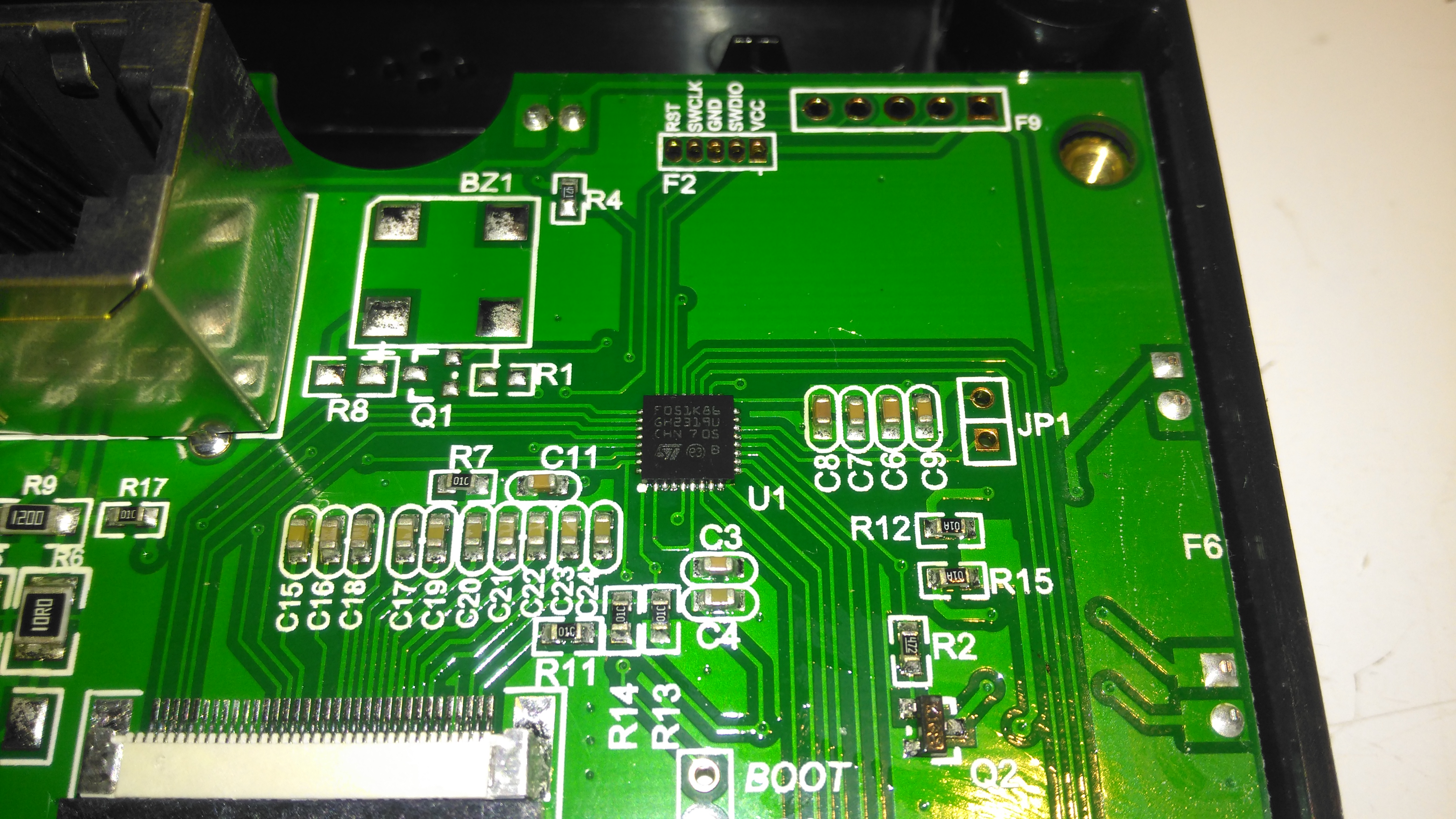
The rear plastic cover is held in place by 4 machine screws, which thread into brass inserts in the plastic frame – nice high quality touch on the design here, no cheap self tapping plastic screws. Both power & data arrive via an Ethernet cable, but the communication here is RS-485, and not compatible with Ethernet! The PCB is pretty sparse, with comms & power on the left, LCD connection in the centre, and the microcontroller on the right.
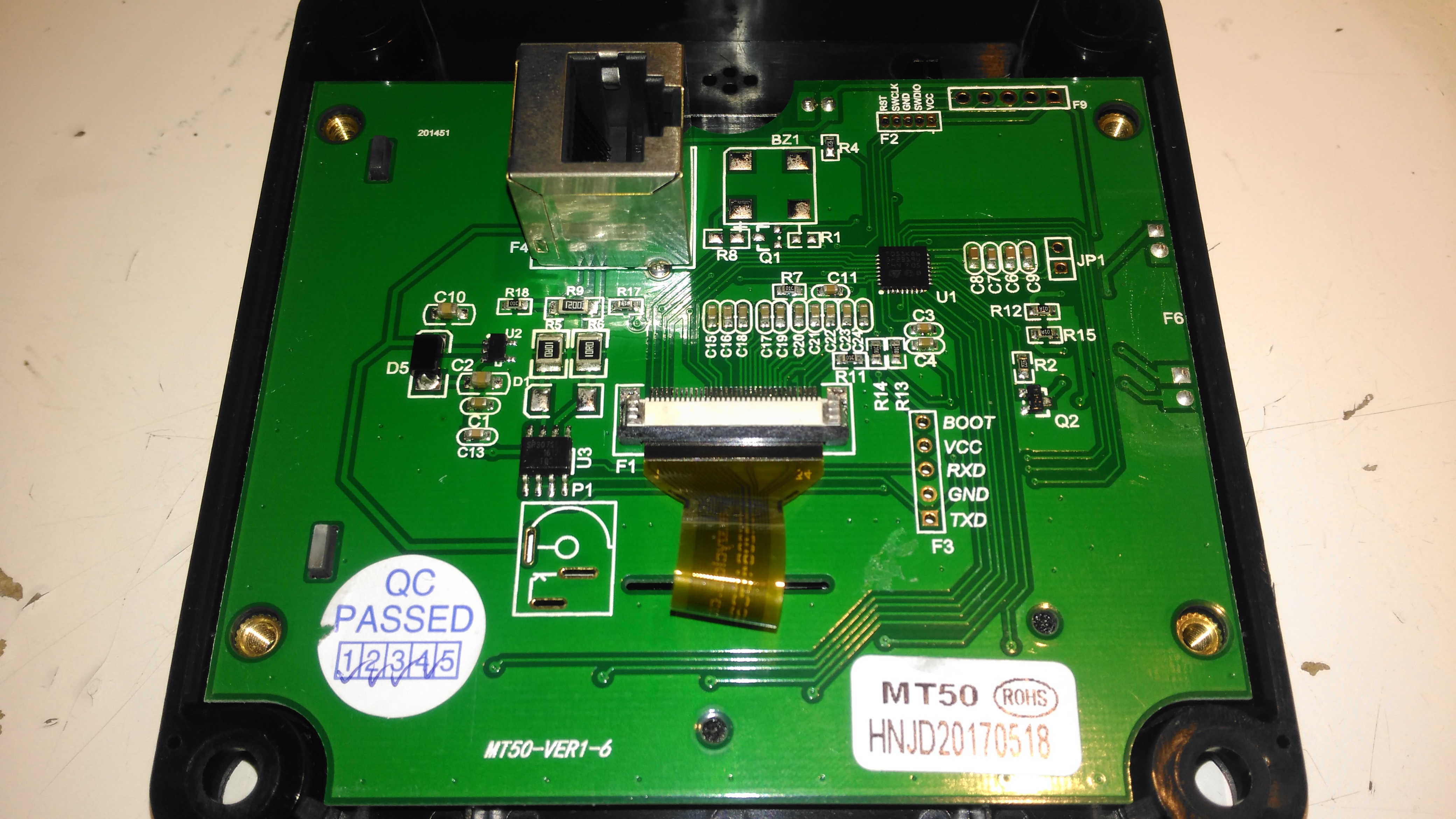
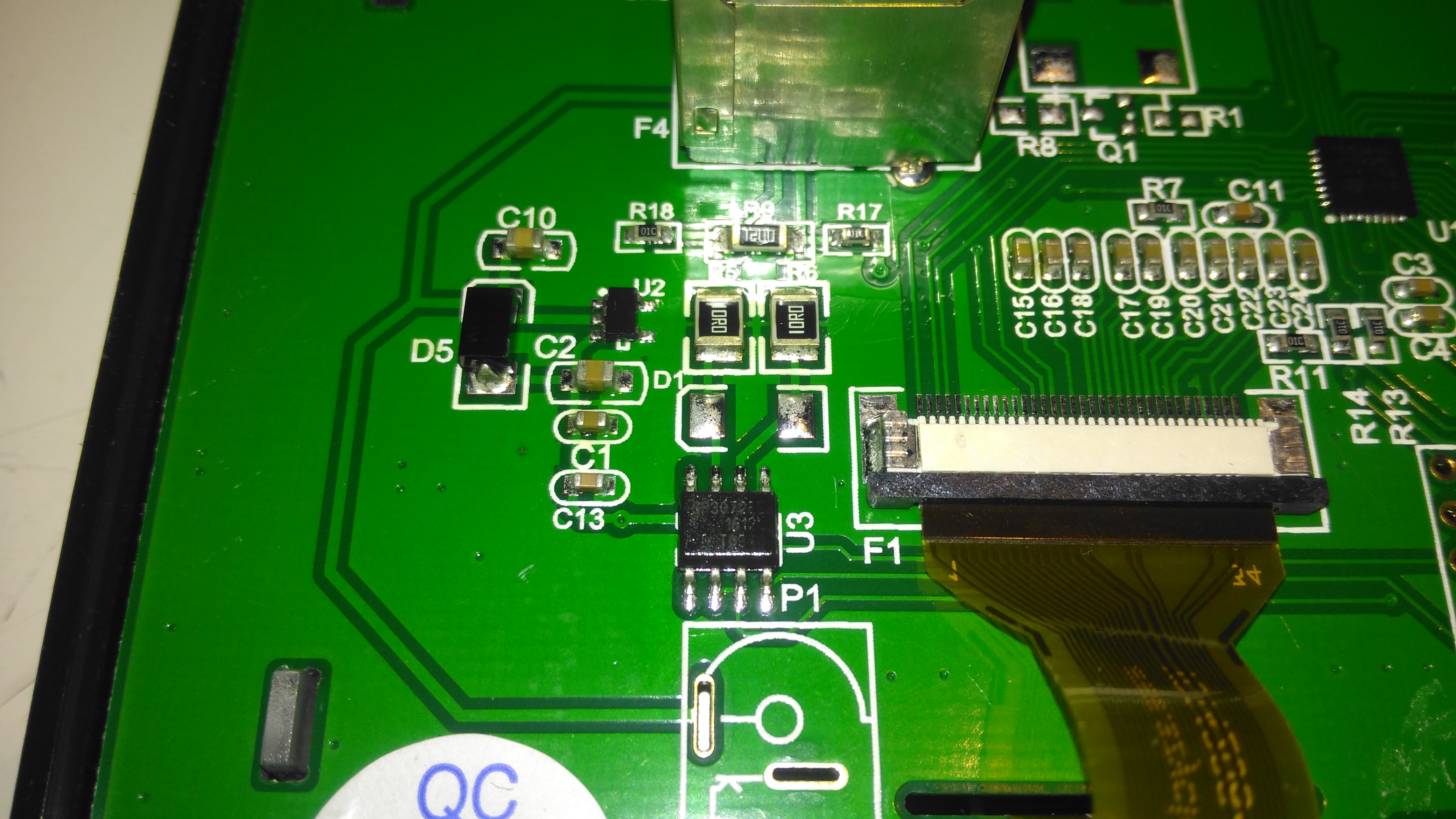
RS-485 Transceiver
On the left of the board is the RS0485 transceiver, and a small voltage regulator. There’s also a spot for a DC barrel jack, which isn’t included in this model for local power supply.
STM32 Microcontroller
The other side of the board holds the main microcontroller which communicates with the charge controller. This is a STM32F051K8 from ST Microelectronics. With a 48MHz ARM Cortex M0 core, and up to 64K of flash, this is a pretty powerful MCU that has very little to do in this application.
PCB Front
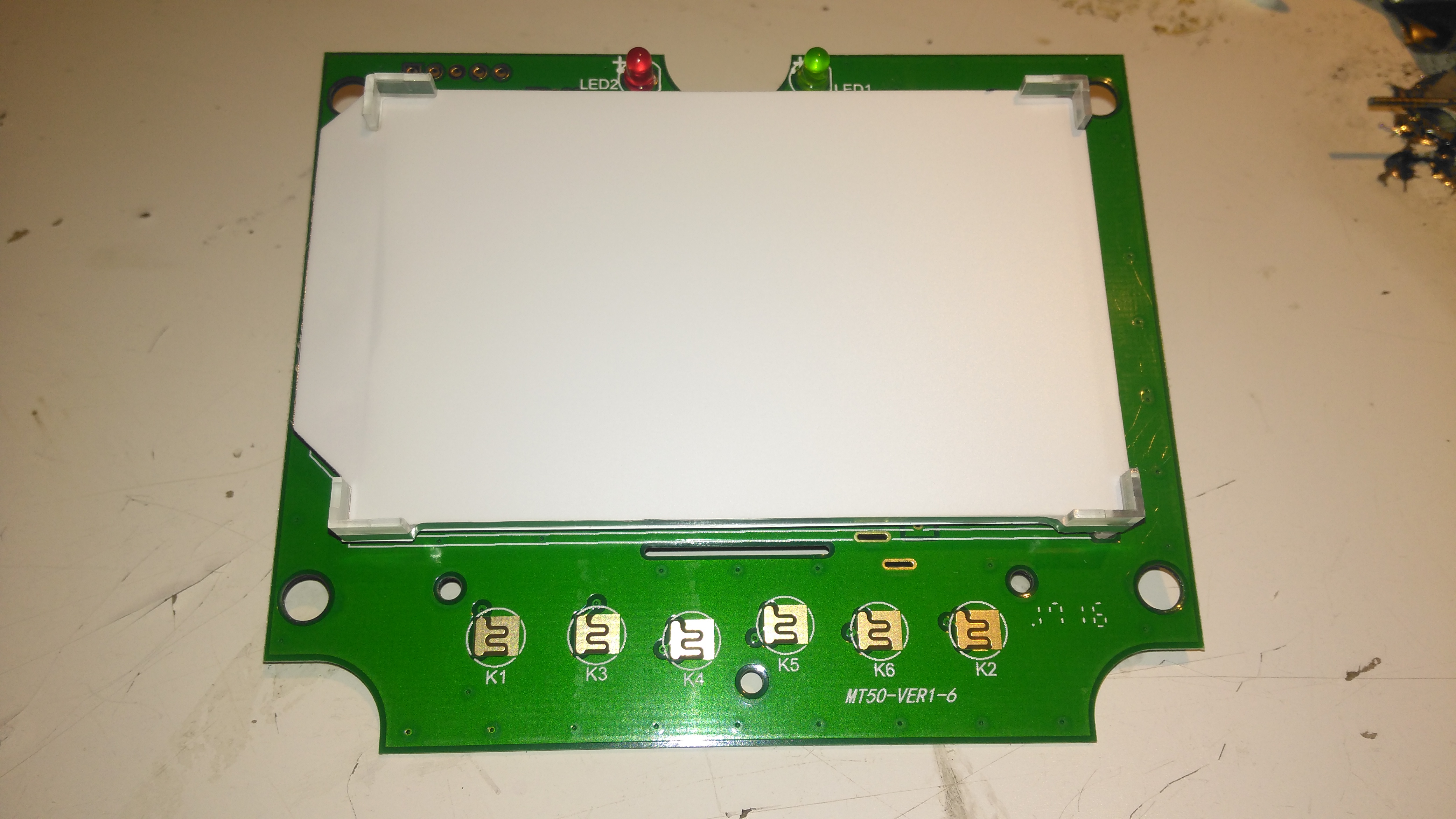
The front of the PCB has the ENIG contacts of the front panel buttons, and the LCD backlight assembly. There’s nothing else under the plastic backlight spreader either.
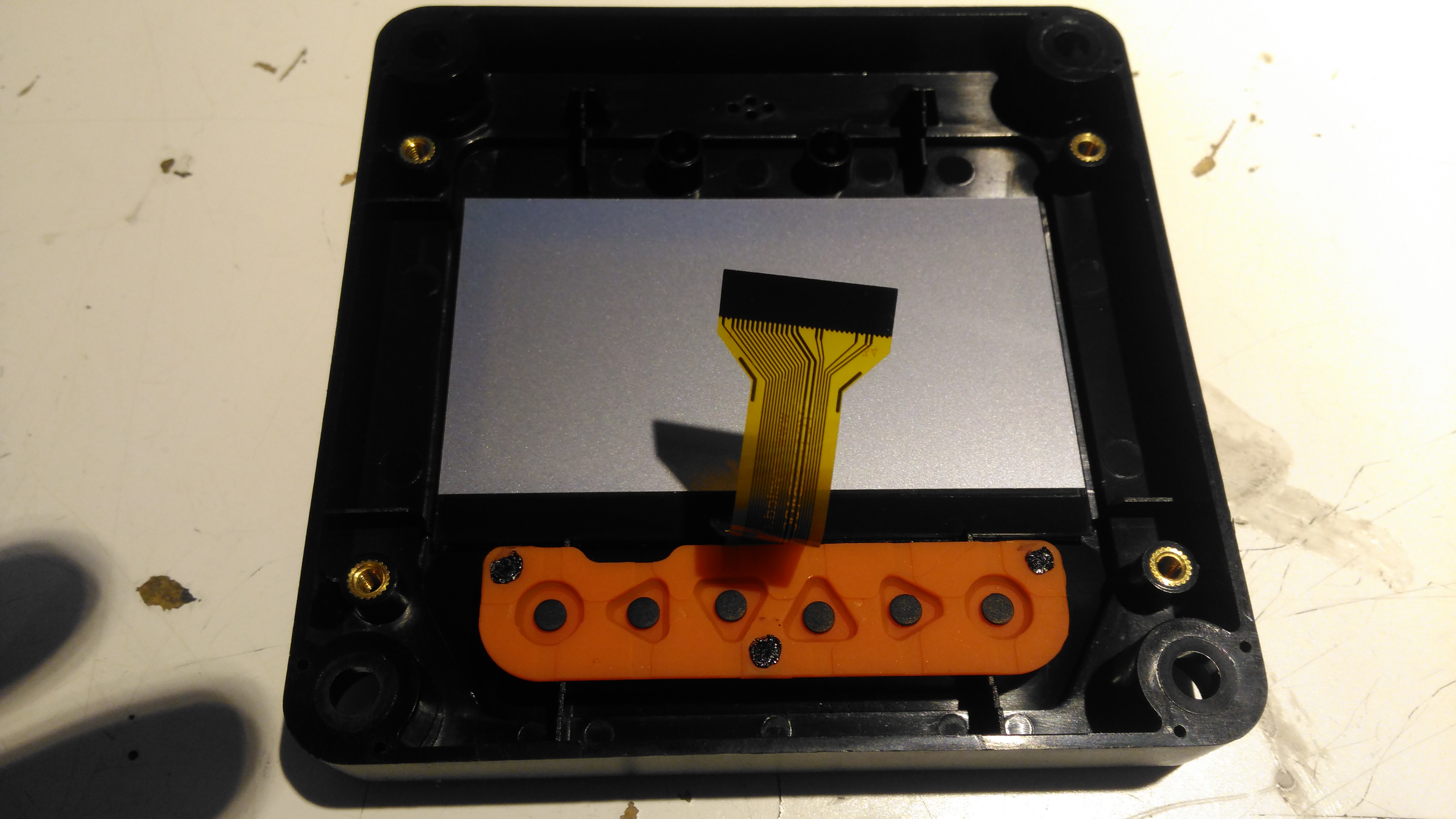
LCD Rear
The front case holds the LCD module in place with glue, and the rubber buttons are placed underneath, which is heat staked in place.
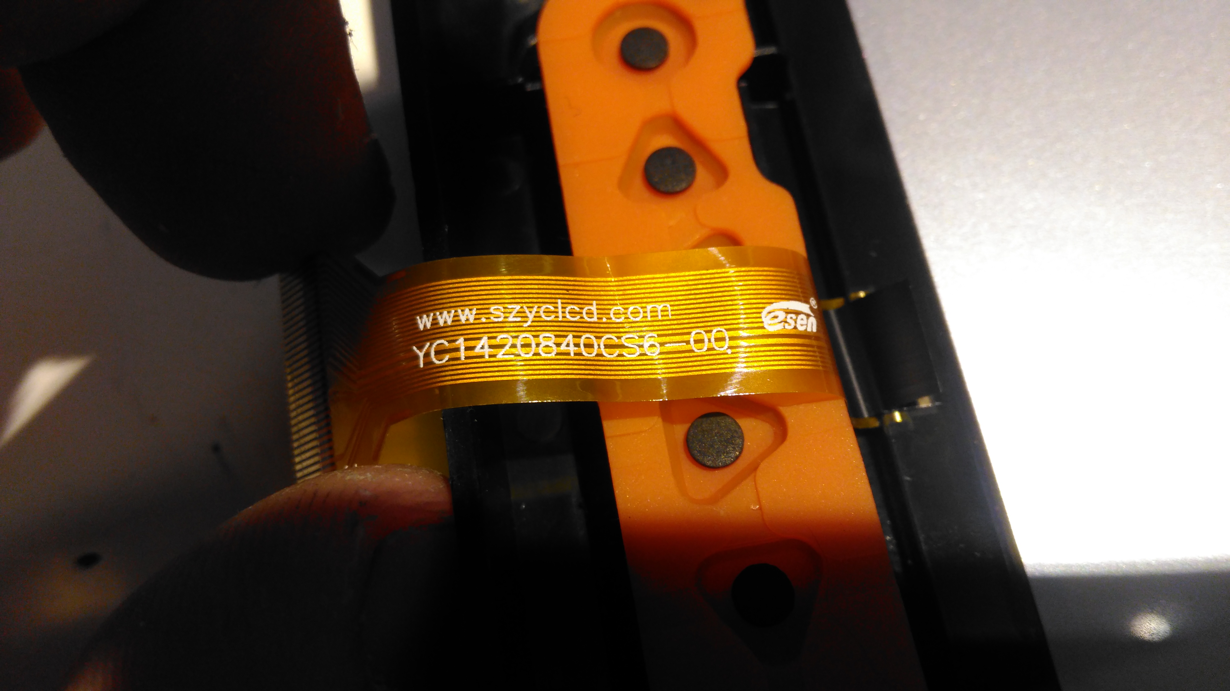
LCD Model
The LCD is a YC1420840CS6 from eCen in China. Couldn’t find much out about this specific LCD.
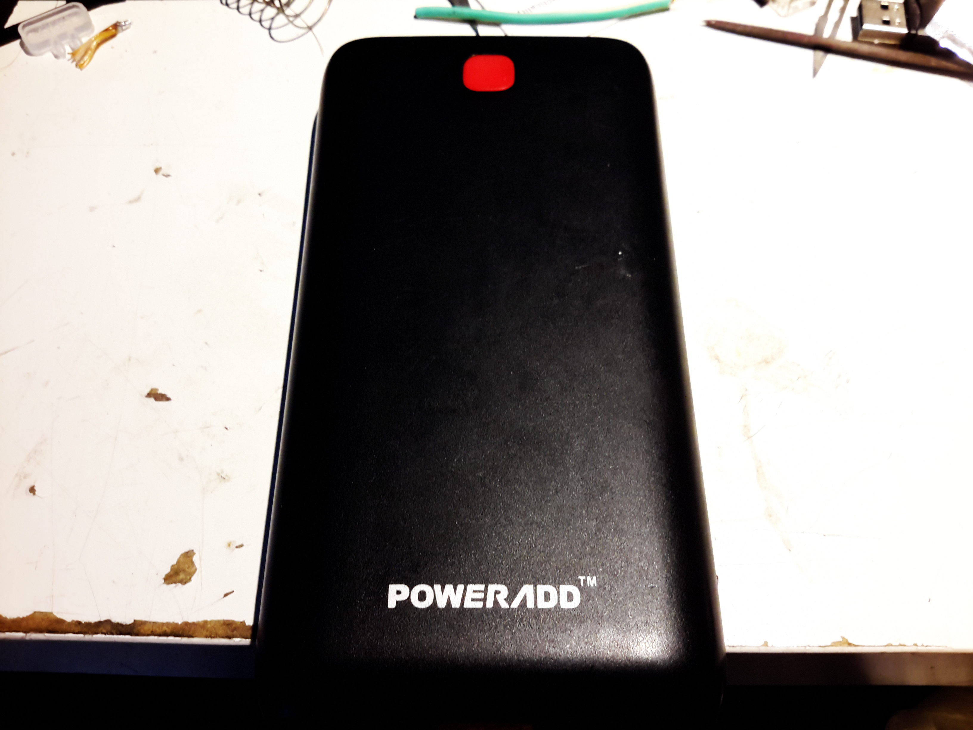
Here’s the biggest portable USB powerbank I’ve seen yet – the PowerAdd Pilot X7, this comes with a 20Ah (20,000mAh) capacity. This pack is pretty heavy, but this isn’t surprising considering the capacity.
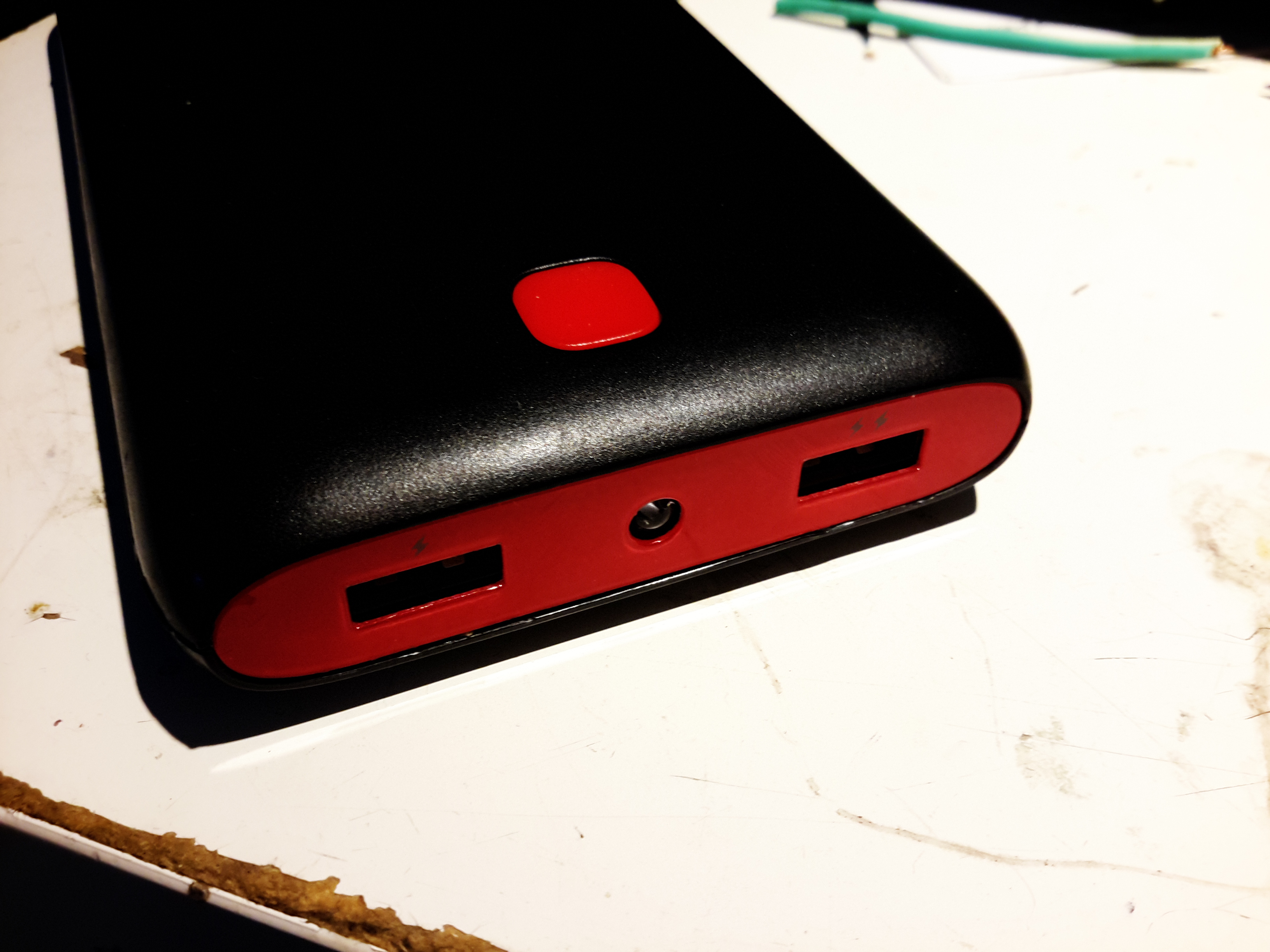
USB Ports & LED
The front of the pack houses the usual USB ports, in this case rated at 3.4A total between the ports. There’s a white LED in the centre as a small torch, activated by double-clicking the button. A single click of the button lights up the 4 blue LEDs under the housing that indicate remaining battery capacity. Factory charging is via a standard µUSB connector in the side, at a maximum of 2A.
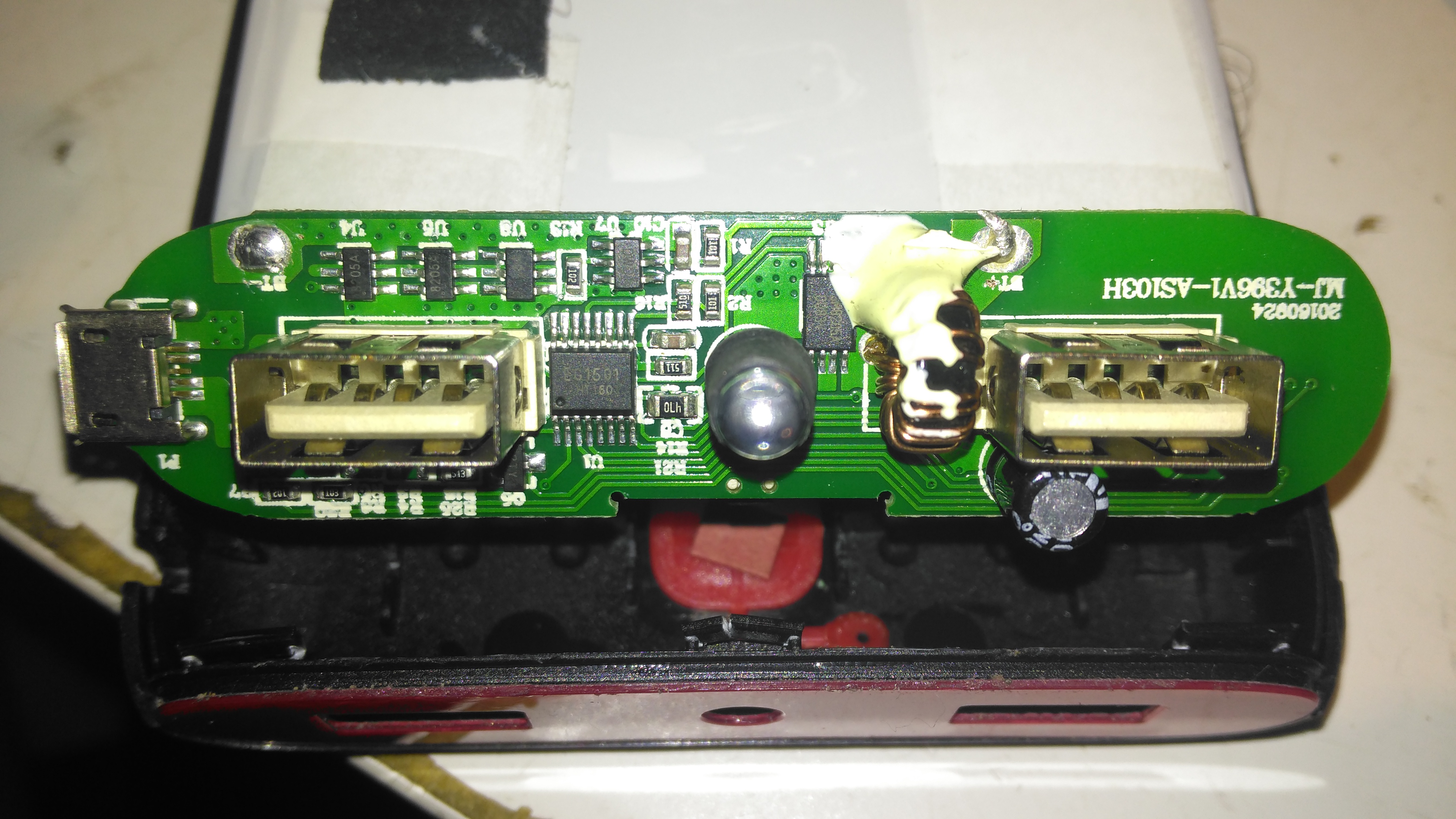
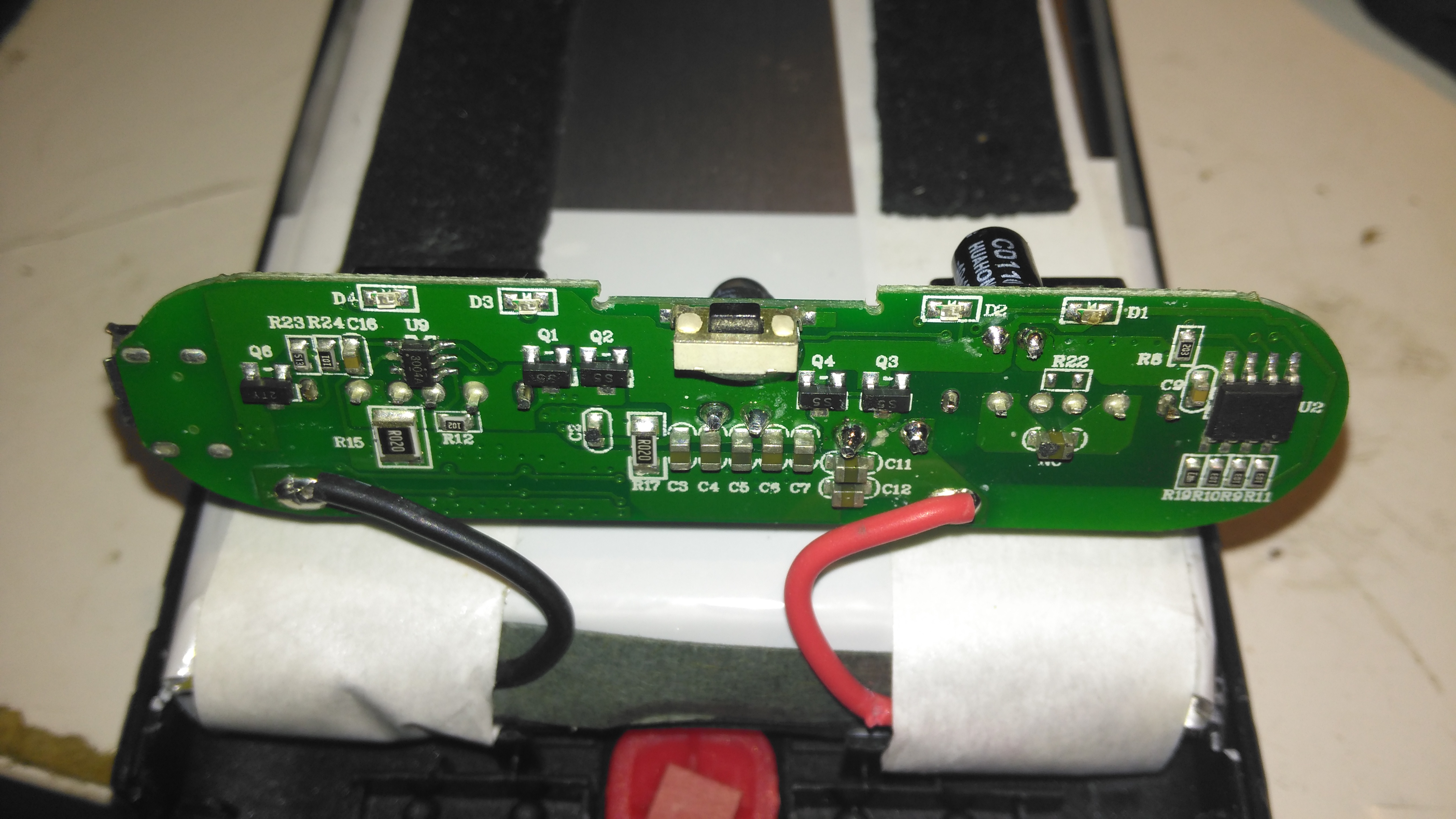
PCB Front
The front of the PCB holds the USB ports, along with most of the main control circuitry. At top left is a string of FS8025A dual-MOSFETs all in parallel for a current carrying capacity of 15A total, to the right of these is the ubiquitous DW01 Lithium-Ion protection IC. These 4 components make up the battery protection – stopping both an overcharge & overdischarge. The larger IC below is an EG1501 multi-purpose power controller.
This chip is doing all of the heavy lifting in this power pack, dealing with all the DC-DC conversion for the USB ports, charge control of the battery pack, controlling the battery level indicator LEDs & controlling the torch LED in the centre.
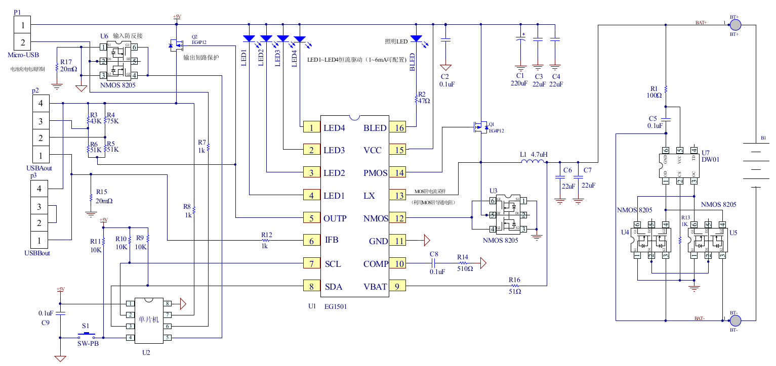
EG1501 Example
The datasheet is in Chinese, but it does have an example application circuit, which is very similar to the circuitry used in this powerbank. A toroidal inductor is nestled next to the right-hand USB port for the DC-DC converter, and the remaining IC next to it is a CW3004 Dual-Channel USB Charging Controller, which automatically sets the data pins on the USB ports to the correct levels to ensure high-current charging of the devices plugged in. This IC replaces the resistors R3-R6 in the schematic above.
The DC-DC converter section of the power chain is designed with high efficiency in mind, not using any diodes, but synchronous rectification instead.
PCB Back
The back of the PCB just has a few discrete transistors, the user interface button, and a small SO8 IC with no markings at all. I’m going to assume this is a generic microcontroller, (U2 in the schematic) & is just there to interface the user button to the power controller via I²C.
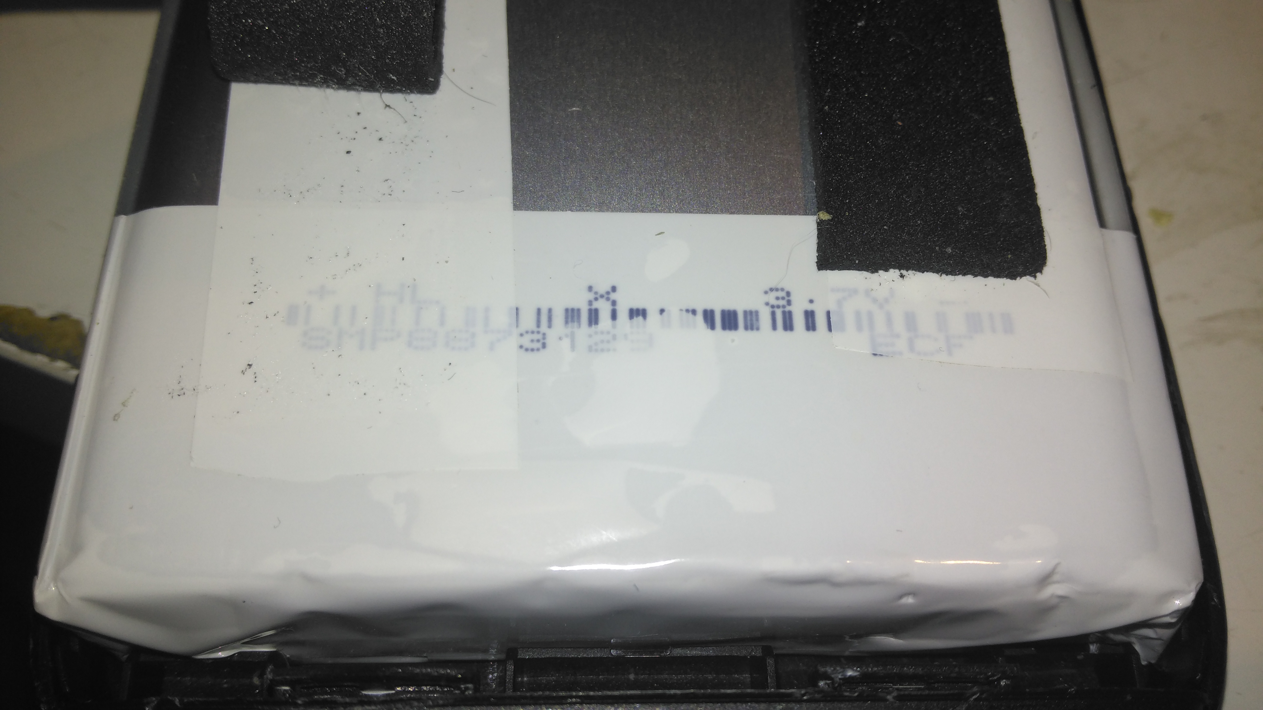
Cells
Not many markings on the cells indicating their capacity, but a full discharge test at 4A gave me a resulting capacity of 21Ah – slightly above the nameplate rating. There are two cells in here in parallel, ~10Ah capacity each.
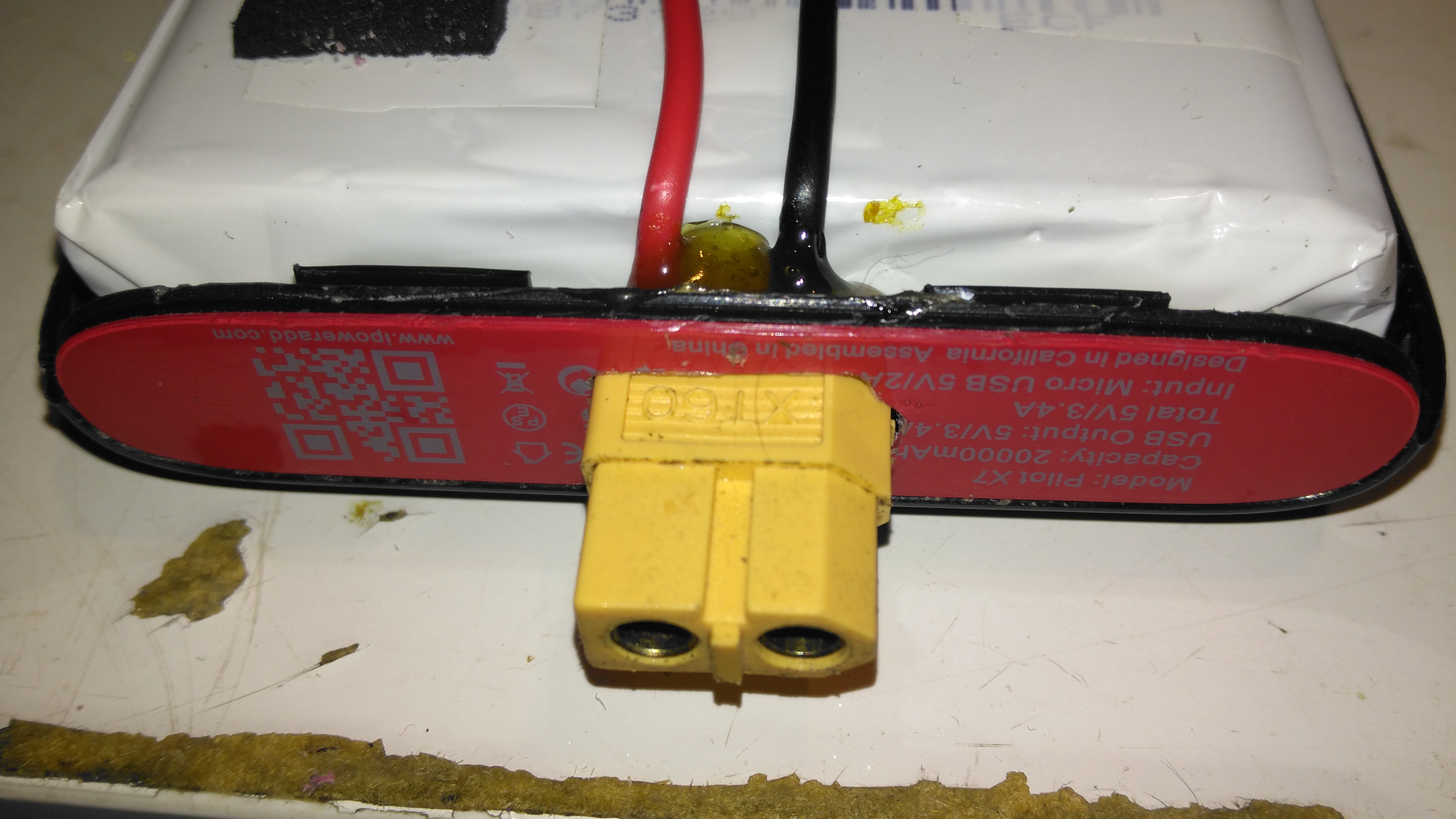
XT60 Battery Connector
The only issue with powerbanks this large is the amount of time they require to recharge themselves – at this unit’s maximum of 2A through the µUSB port, it’s about 22 hours! Here I’ve fitted an XT60 connector, to interface to my Turnigy Accucell 6 charger, increasing the charging current capacity to 6A, and reducing the full-charge time to 7 hours. This splits to 3A charge per cell, and after some testing the cells don’t seem to mind this higher charging current.
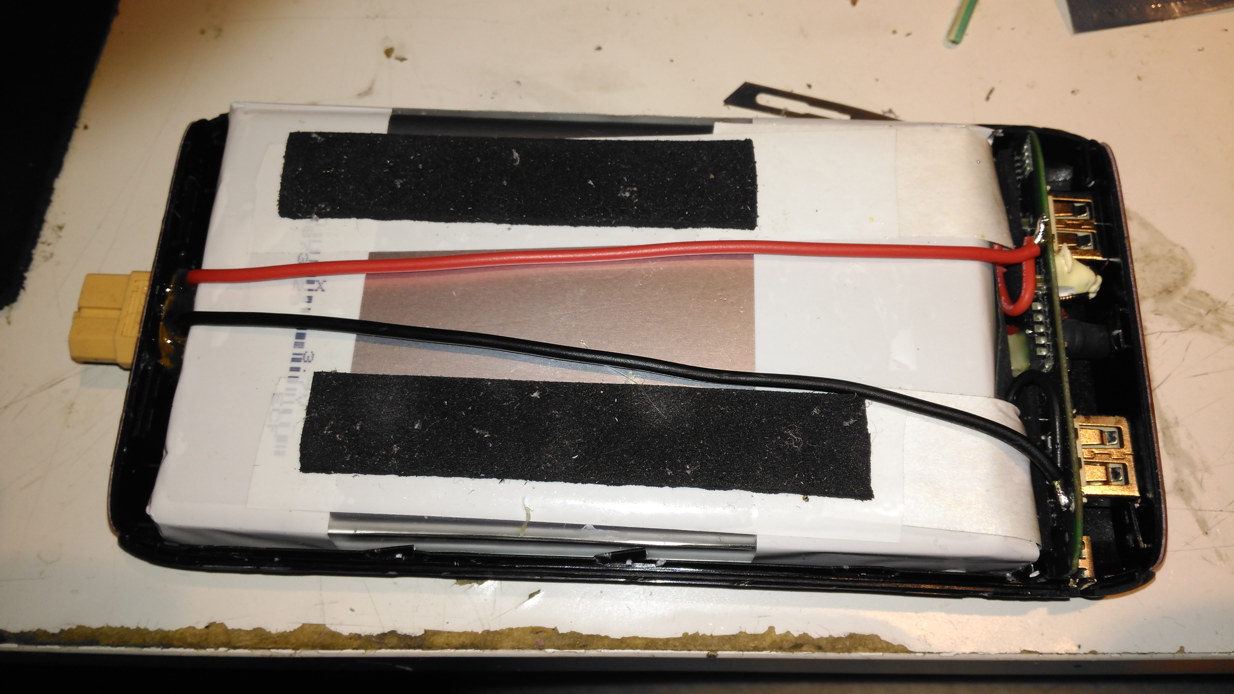
Battery Connector Wiring
The new charging connector is directly connected to the battery at the control PCB, there’s just enough room to get a pair of wires down the casing over the cells.
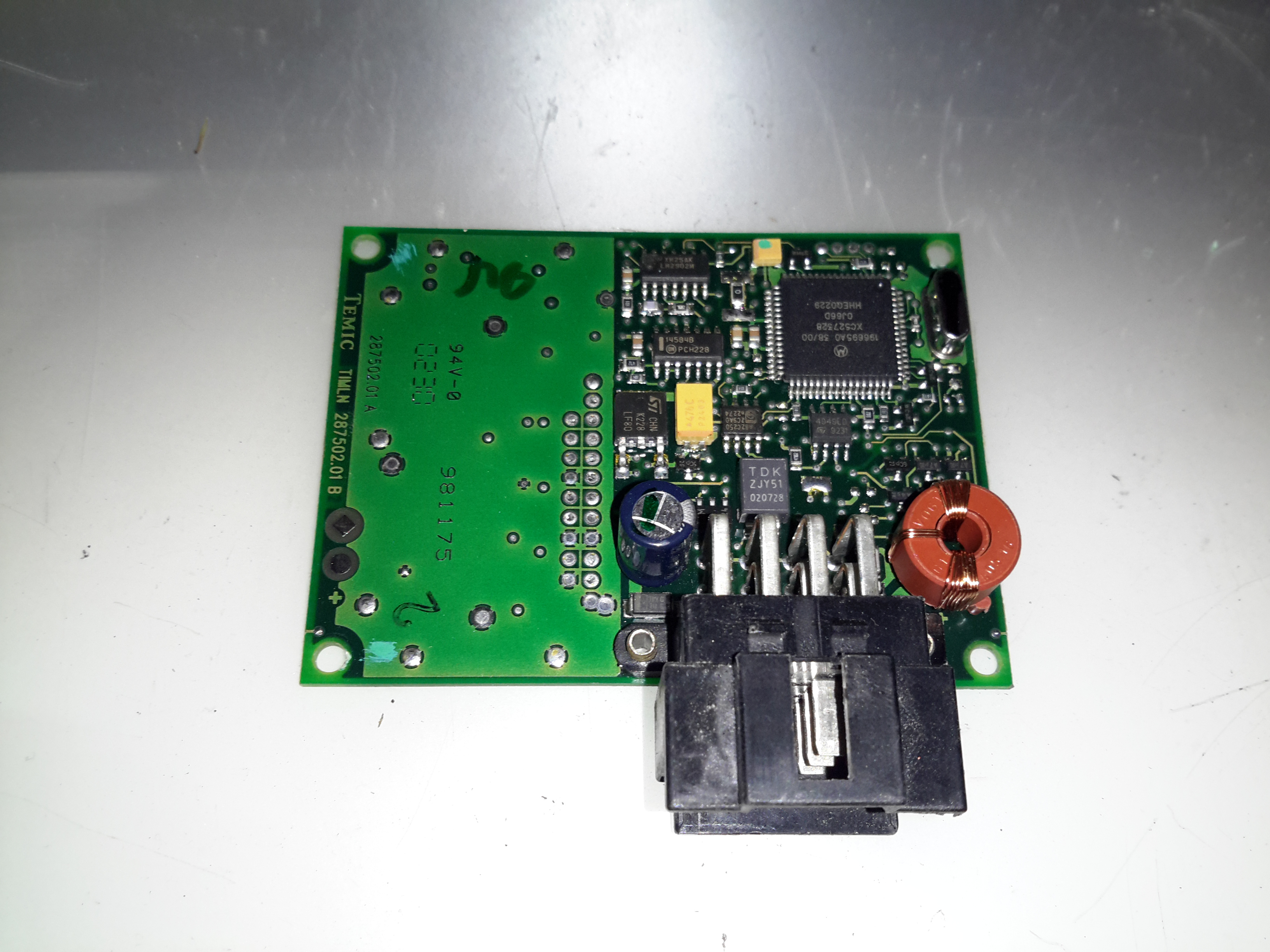
The other day I was given a random pile of car electronic parts from the scrap bin at the local garage, so I decided to do a few teardowns. This first one is a Temic Central Locking / Immobiliser module from a Mercedes van. Judging by the 125kHz stamped on the label, this also has RFID capability.
PCB
The casing just unclips, revealing the PCB. Surprisingly for an automotive module, there is no conformal coating on this (they’re usually heavily coated in protective lacquer to prevent moisture ingress).
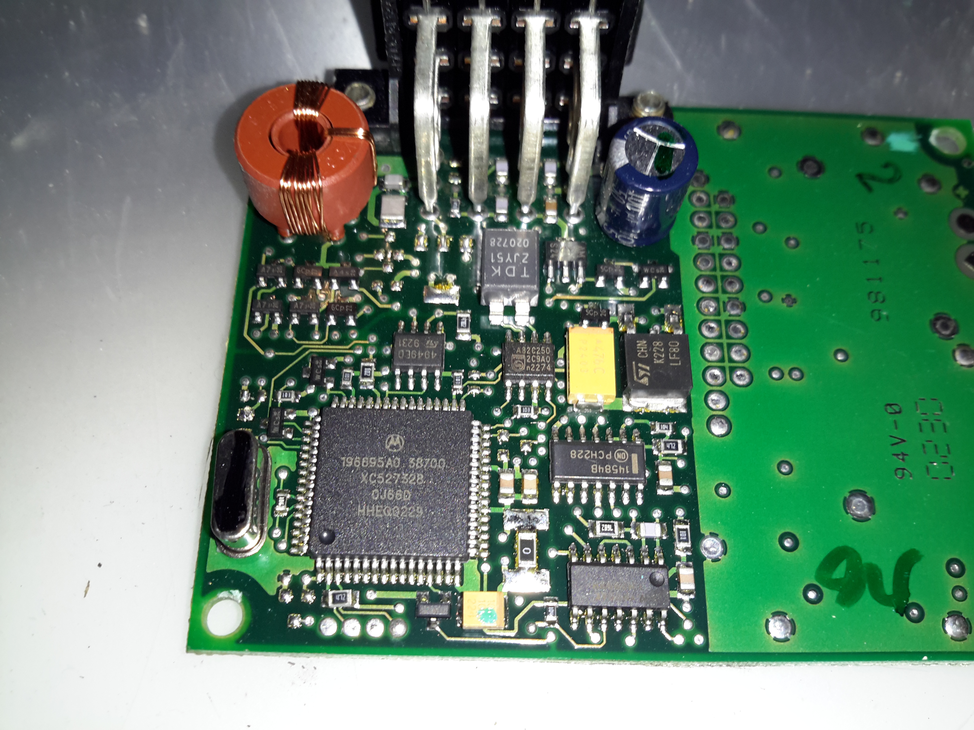
Microcontroller
The large IC from Motorola I’m assuming to be a microcontroller, but I didn’t manage to find anything from the markings. There’s not much else in here apart from some glue logic, and what I think is the 125Khz toroidal antenna in the top left corner.
Here’s a piece of medical equipment that in recent years has become extremely cheap, – a Pulse Oximeter, used to determine the oxygen saturation in the blood. These can be had on eBay for less than £15.
Powered On
This one has a dual colour OLED display, a single button for powering on & adjusting a few settings. These cheap Oximeters do have a bit of a cheap plastic feel to them, but they do seem to work pretty well.
Pulse Oximeter
After a few seconds of being applied to a finger, the unit gives readings that apparently confirm that I’m alive at least. 😉 The device takes a few seconds to get a baseline reading & calibrate the sensor levels.
Main PCB Top
The plastic casing is held together with a few very small screws, but comes apart easily. here is the top of the main board with the OLED display panel. There appears to be a programming header & a serial port on the board as well. I’ll have to poke at these pads with a scope to see if any useful data is on the pins.
Main PCB Bottom
The bottom of the board has all the main components of the system. The microcontroller is a STM32F03C8T6, these are very common in Chinese gear these days. There’s a small piezo beeper & the main photodiode detector is in the centre.
There is an unpopulated IC space on the board with room for support components. I suspect this would be for a Bluetooth radio, as there’s a space at the bottom left of the PCB with no copper planes – this looks like an antenna mounting point. (The serial port on the pads is probably routed here, for remote monitoring).
At the top left are a pair of SGM3005 Dual SPDT analogue switches. These will be used to alternate the red & IR LEDs on the other side of the shell.
A 4-core FFC goes off to the other side of the shell, bringing power from the battery & supplying the sensing LEDs.
Battery Compartment
Power is supplied by a pair of AAA cells in the other shell.
Dual LED
The sensor LEDs are tucked in between the cells, this dual-diode package has a 660nm red LED & a 940nm IR LED.
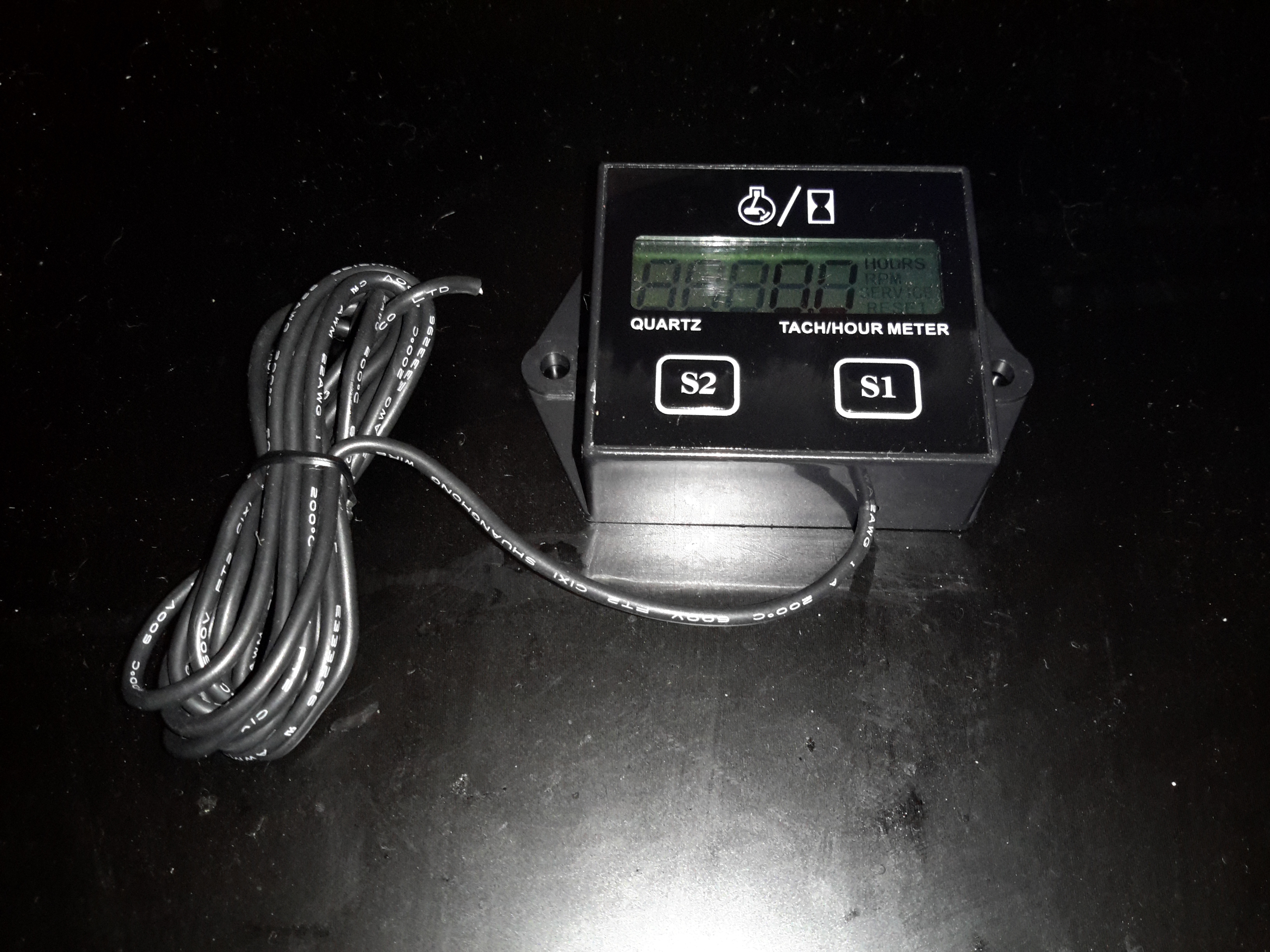
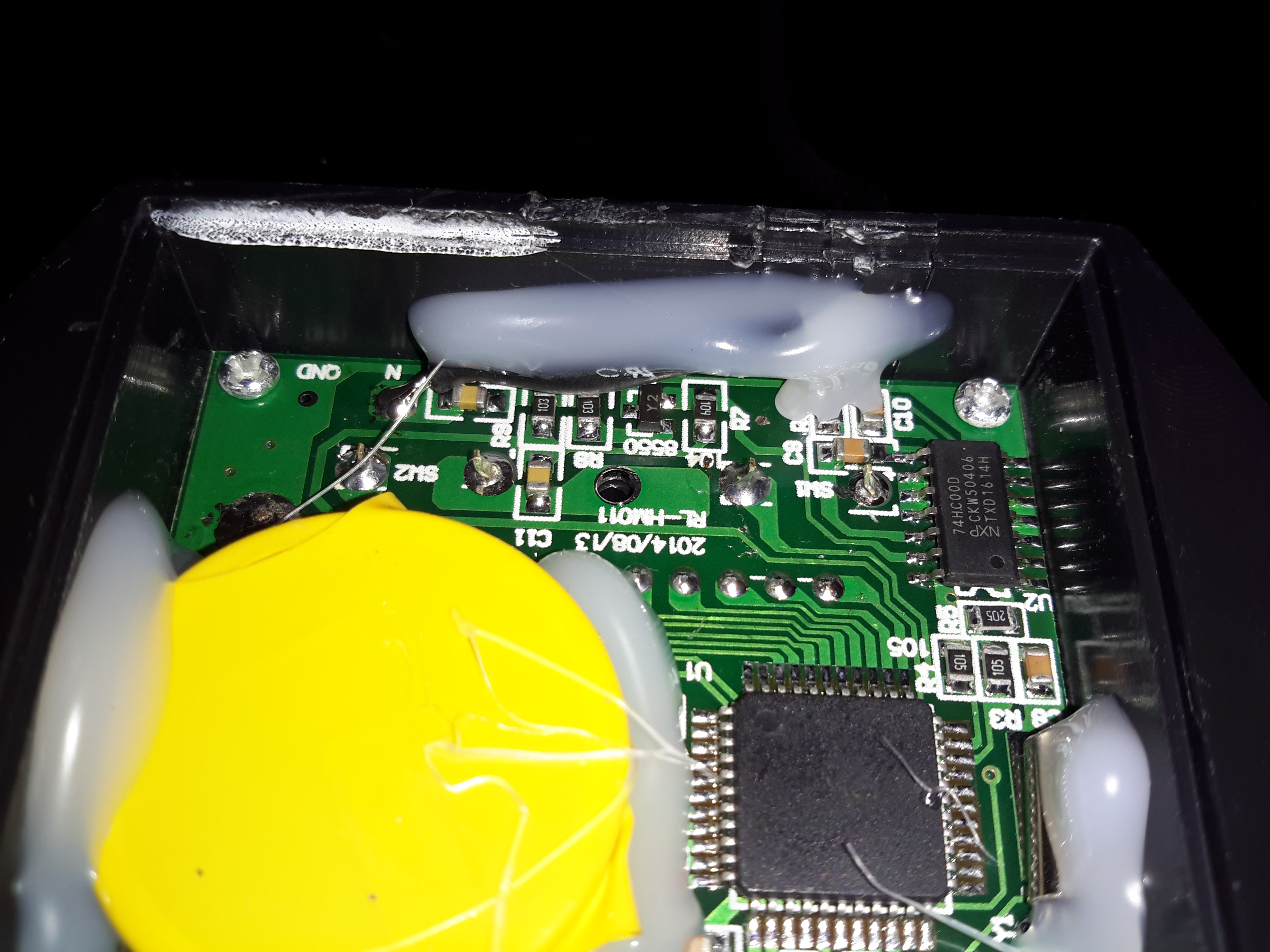
As one of my current projects involves a small petrol engine – a Honda GX35 clone, I figured an hour counter would be very handy to keep an eye on service intervals. (More to come on the engine itself later on). I found a device that would suit my needs on good old eBay.
Inductive Engine Monitor
These engine monitors are pretty cheap, at about £4. The sensing is done by a single heat-resistant silicone wire, that wraps around the HT lead to the spark plug. The unit can be set for different firing intervals via the buttons. In the case of most single-cylinder 4-stroke engines, the spark plug fires on every revolution – wasted-spark ignition. This simplifies the ignition system greatly, by not requiring the timing signal be driven from 1/2 crankshaft speed. The second “wasted” spark fires into the exhaust stroke, so has no effect.
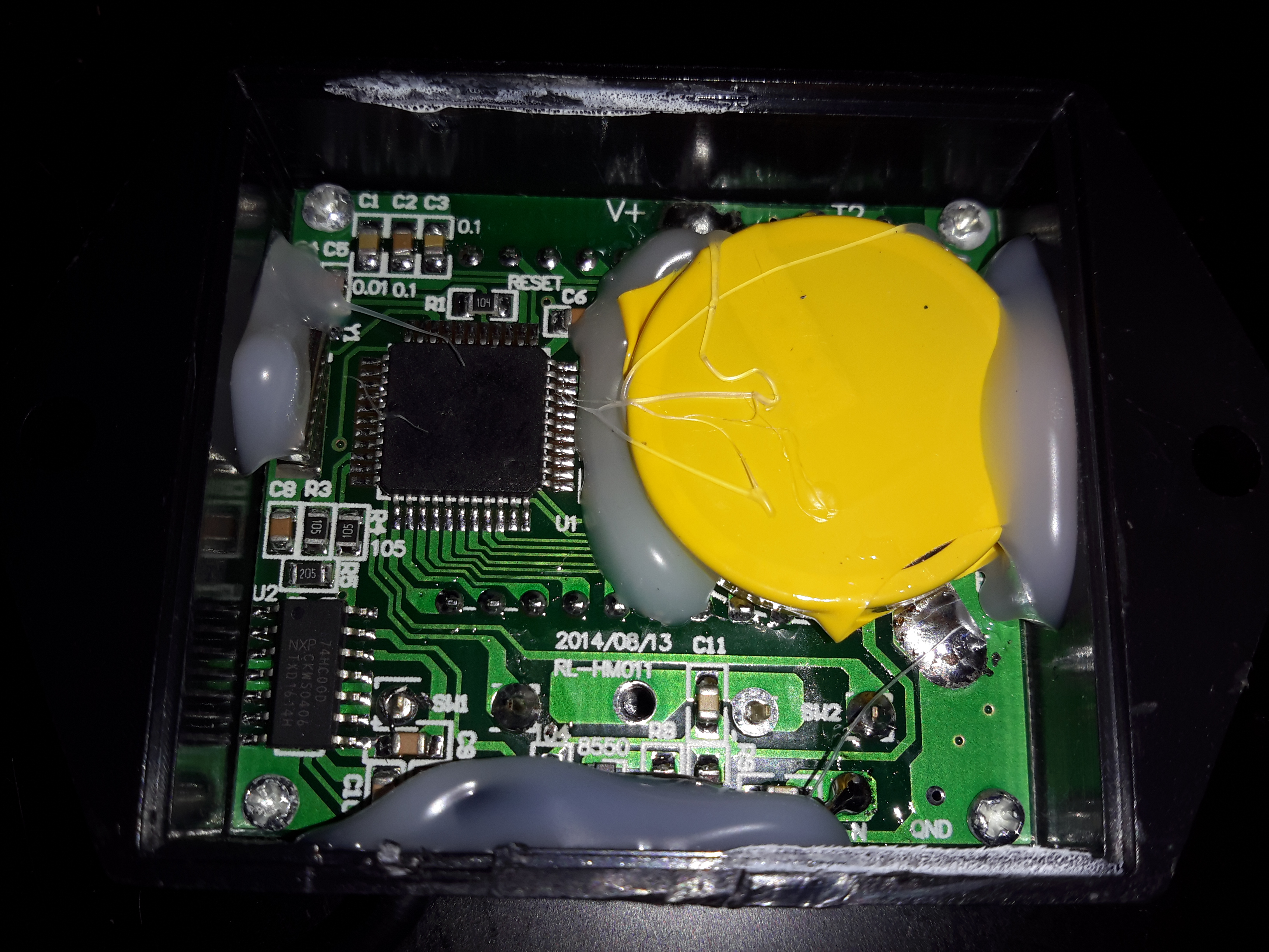
Internals
The back cover is lightly glued into place with a drop of cyanoacrylate in opposite corners, but easily pops off. The power is supplied by a soldered-in 3v Lithium cell. The main microcontroller has no number laser etched on to it at all – it appears it skipped the marking machine.
Input Filtering
The input from the sensing wire comes in through a coupling capacitor & is amplified by a transistor. It’s then fed into a 74HC00D Quad 2-Input NAND gate, before being fed into the microcontroller.
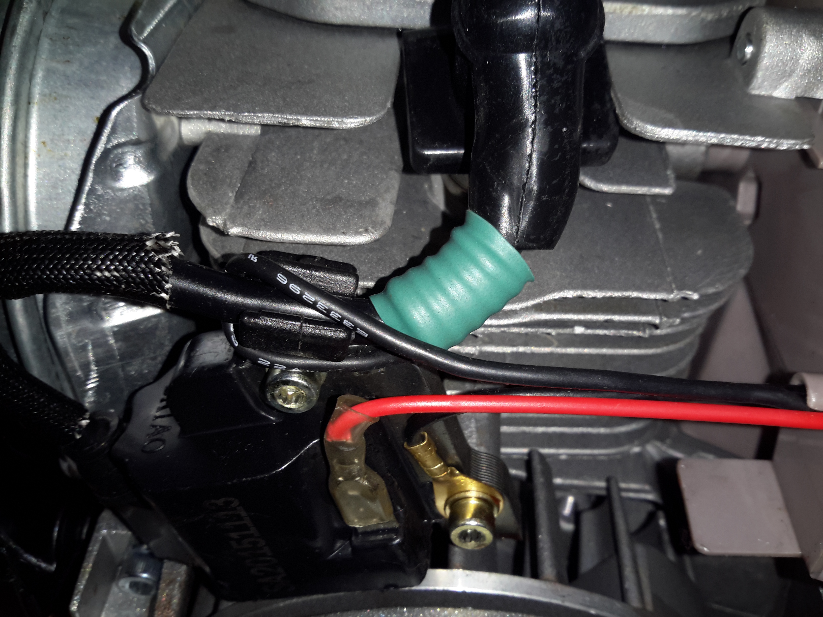
Pickup
The pickup wire is simply wound around the spark plug lead. I’ve held it in position here with some heatshrink tubing. Heat in this area shouldn’t be an issue as it’s directly in the airflow from the flywheel fan.
Time foe some more retro tech! This is a 1980’s vintage CCD-based VHS camcorder from Panasonic, the NV-M5. There are a lot of parts to one of these (unlike modern cameras), so I’ll split this post into several sections to make things easier to read (and easier to keep track of what I’m talking about :)).
Left Side
The left side of the camera holds the autofocus, white balance, shutter speed & date controls.
Left Side ControlsLens Adjustments
The lens is fully adjustable, with either manual or motorized automatic control.
Rear Panel
The back panel has the battery slot, a very strange looking DC input connector, remote control connector & the earphone jack.
Top Controls
The top panel of the camera holds the main power controls, manual tape tracking & the tape transport control panel.
Viewfinder
The viewfinder is mounted on a swivel mount. There’s a CRT based composite monitor in here. Hack ahoy!
Camera Section
Process Board Assembly
Here’s the camera section of the camcorder, and is totally packed with electronics! There’s at least half a dozen separate boards in here, all fitted together around the optics tube assembly.
AWB PCB
On the top of the assembly is the Automatic White Balance PCB. Many adjustments here to get everything set right. Not much on the other side of this board other than a bunch of Op-Amps. The iris stepper motor is fitted in a milled opening in the PCB, this connects to one of the other PCBs in the camera module.
AWB Sensor
Here’s the AWB sensor, mounted next to the lens. I’m not all to certain how this works, but the service manual has the pinout, and there are outputs for all the colour channels, RGB. So it’s probably a trio of photodiodes with filters.
Focus & Zoom Motors
Focus & Zoom are controlled with a pair of DC gear motors. The manual operation is feasible through the use of slip clutches in the final drive pinion onto the lens barrel.
Process Board
The main camera section process board is above. This board does all the signal processing for the CCD, has the bias voltage supplies and houses the control sections for the motorized parts of the optics assembly. There are quite a few dipped Tantalum capacitors on pigtails, instead of being directly board mounted. This was probably done due to space requirements on the PCB itself.
Under the steel shield on this board is some of the main signal processing for the CCD.
Optics Assembly
The back of the optics tube is a heavy casting, to supress vibration. This will be more clear later on.
Position Sensor Flex
The position of the lens elements is determined by reflective strips on the barrel & sensors on this flex PCB.
Sub Process Board
There’s another small board tucked into the side of the tube, this hooks into the process PCB.
Process Delay Line
According to the schematic, there’s nothing much on this board, just a delay line & a few transistors.
Piezo Focus Disc
Here’s the reason for the heavy alloy casing at the CCD mounting end of the optics: the fine focus adjustment is done with a piezoelectric disc, the entire CCD assembly is mounted to this board. Applying voltage to the electrodes moves the assembly slightly to alter the position of the CCD. The blue glass in the centre of the unit is the IR filter.
IR Relective Sensors
The barrel position sensors are these IR-reflective type.
Iris Assembly
The iris is mounted just before the CCD, this is controlled with a galvanometer-type device with position sensors incorporated.
Iris Opening
Pushing on the operating lever with the end of my screwdriver opens the leaves of the iris against the return spring.
Tape Transport & Main Control
Main Control Board
Tucked into the side of the main body of the unit is the main system control board. This PCB houses all the vital functions of the camera: Power Supply, Servo Control, Colour Control,Video Amplifiers, etc.
Tape Drum
Here’s the main tape transport mechanism, this is made of steel & aluminium stampings for structural support. The drum used in this transport is noticeably smaller than a standard VHS drum, the tape is wrapped around more of the drum surface to compensate.
Tape Transport
The VHS tape sits in this carriage & the spools drive the supply & take up reels in the cartridge.
Main Control PCB
Here’s the component side of the main control PCB. This one is very densely packed with parts, I wouldn’t like to try & troubleshoot something like this!
Main PCB Left
The left side has the video head amp at the top, a Panasonic AN3311K 4-head video amp. Below that is video processing, the blue components are the analogue delay lines. There are a couple of hybrid flat-flex PCBs tucked in between with a couple of ICs & many passives. These hybrids handle the luma & chroma signals.
Top left is the capstan motor driver a Rohm BA6430S. The transport motors are all 3-phase brushless, with exception of the loading motor, which is a brushed DC type.
Delay Line
Here’s what is inside the delay lines for the analogue video circuits. The plastic casing holds a felt liner, inside which is the delay line itself.
Internal Glass
The delay is created by sending an acoustic signal through the quartz crystal inside the device by a piezoelectric transducer, bouncing it off the walls of the crystal before returning it to a similar transducer.
Main PCB Centre
Here’s the centre of the board, the strange crystal at bottom centre is the clock crystal for the head drum servo. Why it has 3 pins I’m not sure, only the two pins to the crystal inside are shown connected on the schematic. Maybe grounding the case?
The main servo controls for the head drum & the capstan motor are top centre, these get a control signal from the tape to lock the speed of the relative components.
Main PCB Right
Here’s the right hand side. The main power supply circuitry is at top right, with a large can containing 4 switching inductors & a ferrite pot core transformer. All these converters are controlled by a single BA6149 6-channel DC-DC converter controller IC via a ULN2003 transistor array.
The ceramic hybrid board next to the PSU has 7 switch transistors for driving various indicator LEDs.
The large tabbed IC bottom centre is the loading motor drive, an IC from Mitsubishi, the M54543. This has bidirectional DC control of the motor & built in braking functions. The large quad flat pack IC on the right is the MN1237A on-screen character generator, with the two clock crystals for the main microcontroller.
Erase Head
The full erase head has it’s power supply & oscillator on board, applying 9v to this board results in an AC signal to the head, which erases the old recording from the tape before the new recording is laid down by the flying heads on the drum.
Audio Control PCB
The Audio & Control head is connected to this PCB, which handles both reading back audio from the tape & recording new audio tracks. The audio bias oscillator is on this board, & the onboard microphone feeds it’s signal here. The control head is fed directly through to the servo section of the main board.
Drum Motor
The motor that drives the head drum is another DC brushless 3-phase type.
Hall Sensors
These 3 Hall sensors are used by the motor drive to determine the rotor position & time commutation accordingly.
Stator
The stator on this motor is of interesting construction, with no laminated core, the coils are moulded into the plastic holder. The tach sensor is on the side of the stator core. This senses a small magnet on the outside of the rotor to determine rotational speed. For PAL recordings, the drum rotates at 1500 RPM.
Motor Removed
Not much under the stator other than the bearing housing & the feedthrough to the rotary transformer.
Head Disc
The heads are mounted onto the top disc of the drum, 4 heads in this recorder. The signals are transmitted to the rotating section through the ferrite rotary transformer on the bottom section.
Head Chip
The tiny winding of the ferrite video head can just about be seen on the end of the brass mounting.
Capstan Motor Components
The capstan motor is similar to the drum motor, only this one is flat. The rotor has a ferrite magnet, in this case it wasn’t glued in place, just held by it’s magnetic field.
Capstan Motor Stator
The PCB on this motor has a steel backing to complete the magnetic circuit, the coils for the 3 motor phases are simply glued in place. The Hall sensors on this motor are placed in the middle of the windings though.
Again there is a tach sensor on the edge of the board that communicates the speed back to the controller. This allows the servo to remain locked at constant speed.
Viewfinder
Viewfinder Assembly
As usual with these cameras, this section is the CRT based viewfinder. These units take the composite signal from the camera to display the scene. This one has many more pins than the usual viewfinder. I’ll hack a manual input into this, but I’ll leave that for another post.
Viewfinder Circuits
Being an older camera than the ones I’ve had before, this one is on a pair of PCBs, which are both single-sided.
Main Viewfinder Board
The main board has all the power components for driving the CRT & some of the adjustments. The main HV flyback transformer is on the right. This part creates both the final anode voltage for the tube & the focus/grid voltages.
Viewfinder Control PCB Top
The viewfinder control IC is on a separate daughter board in this camera, with two more controls.
Control IC
The control IC is a Matsushita AN2510S, this has all the logic required to separate the sync pulses from the composite signal & generate an image on the CRT.
Viewfinder CRT Frame
The recording indicator LEDs are mounted in the frame of the CRT & appear above the image in the viewfinder.
Viewfinder CRT With Yoke
Here the CRT has been separated from the rest of the circuitry with just the deflection yoke still attached.
M01JPG5WB CRT
The electron gun in this viewfinder CRT is massive in comparison to the others that I have seen, and the neck of the tube is also much wider. These old tubes were very well manufactured.
Viewfinder Optics
A simple mirror & magnifying lens completes the viewfinder unit.
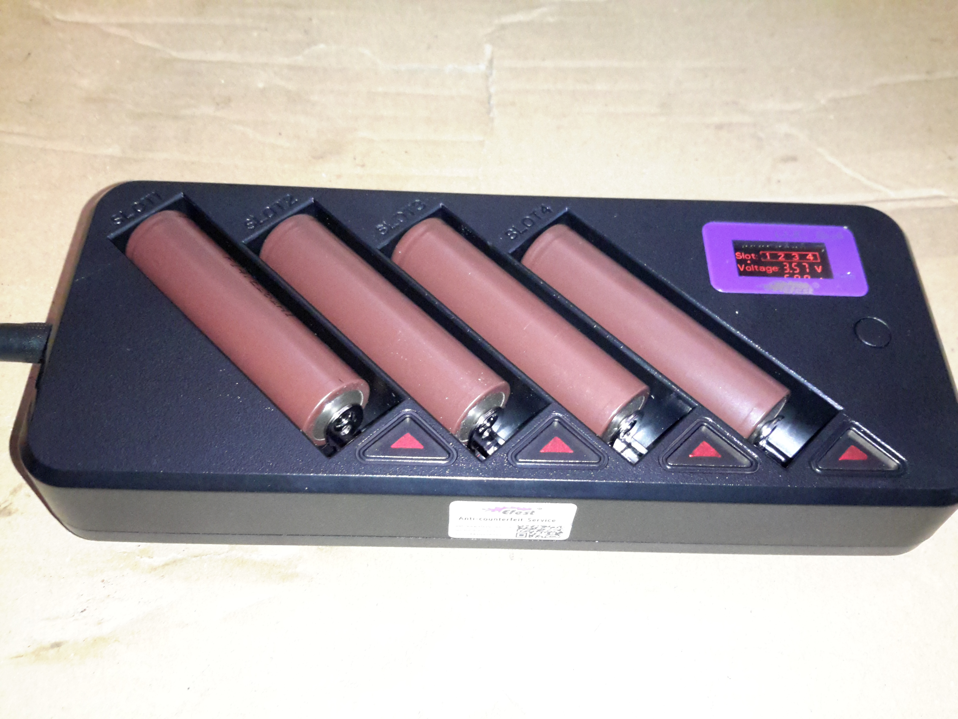
Here’s another battery charger designed for lithium chemistry cells, the BLU4. This charger doesn’t display much on it’s built in LCD, apart from basic cell voltage & charging current limits, as it has a built in Bluetooth module that will link into an Android or iOS app.
Above the charger is operating with 4 brand new cells, at a current of 500mA per cell. If only a pair of cells is being charged, the current can be increased to 1A per cell.
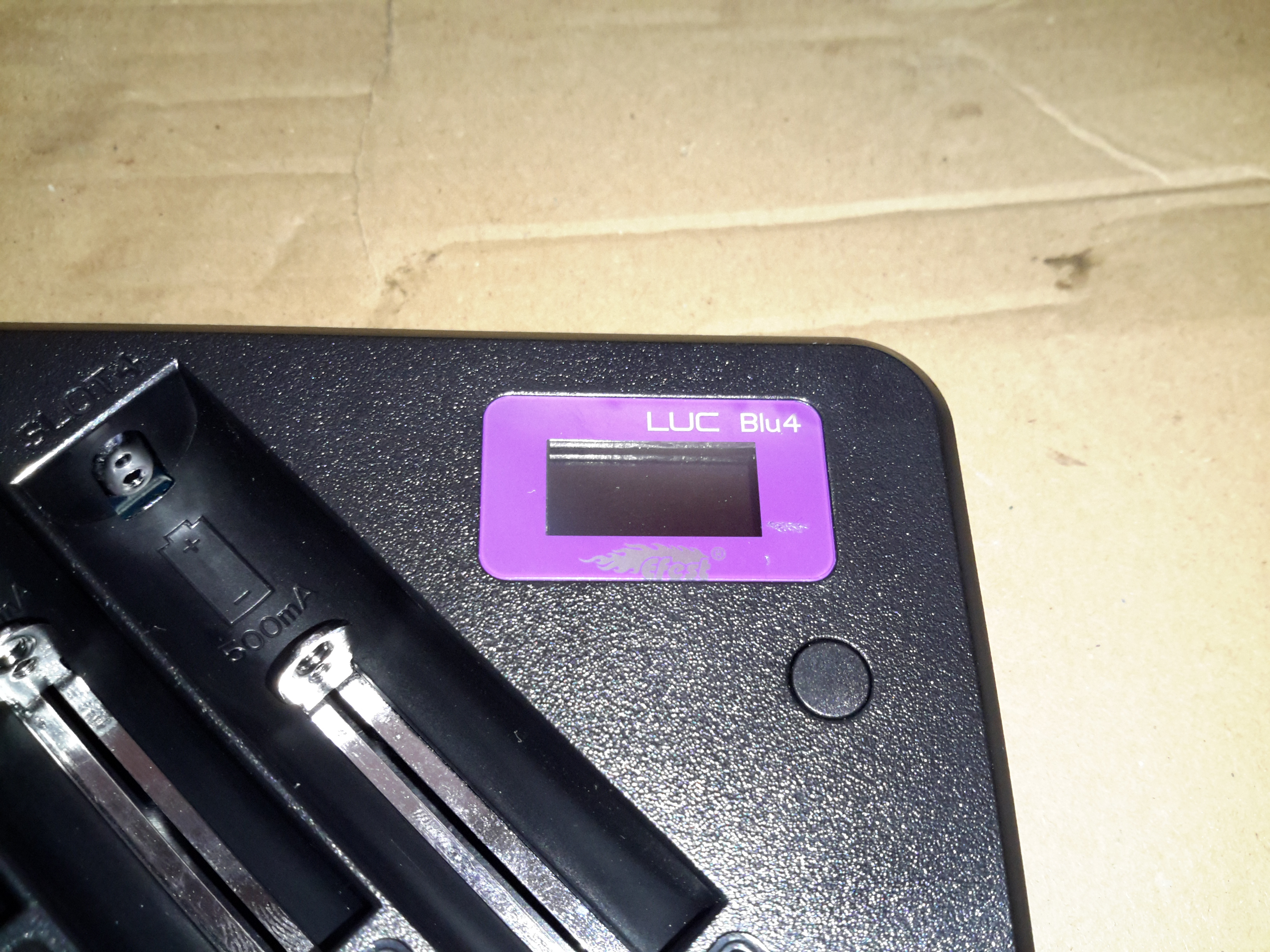
LCD
Not much in the way of user interface on the charger, a tiny LCD & single button for cycling through the display options.
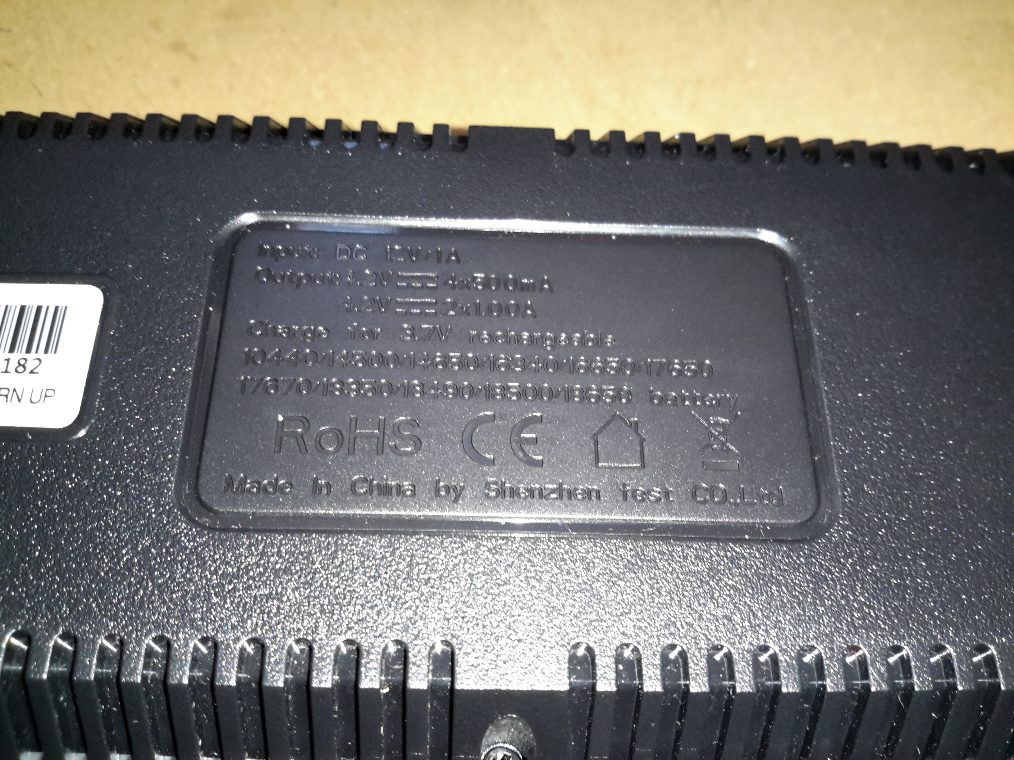
Dataplate
The usual stuff on the data plate, the charger accepts an input of 12v DC at 1A.
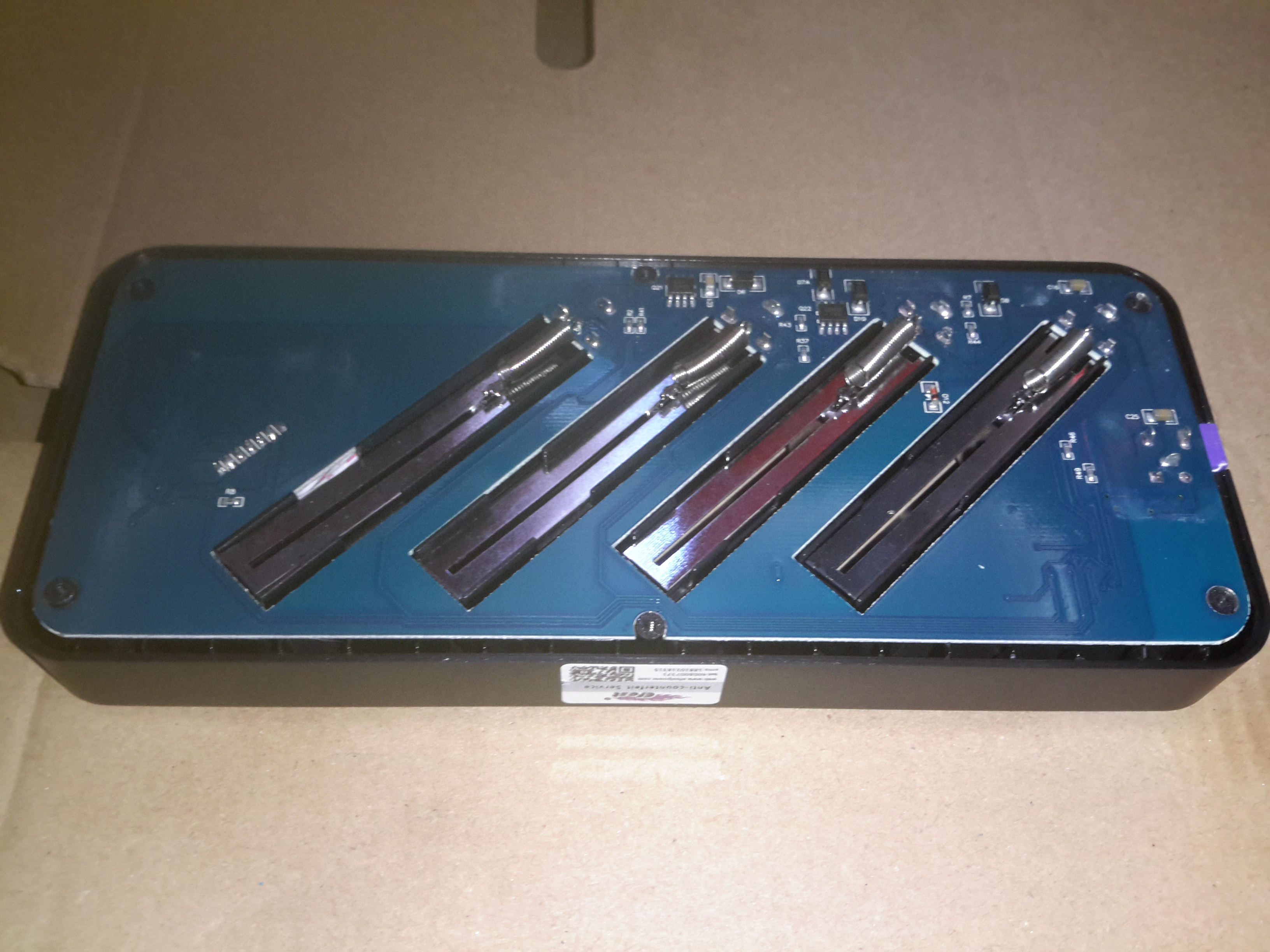
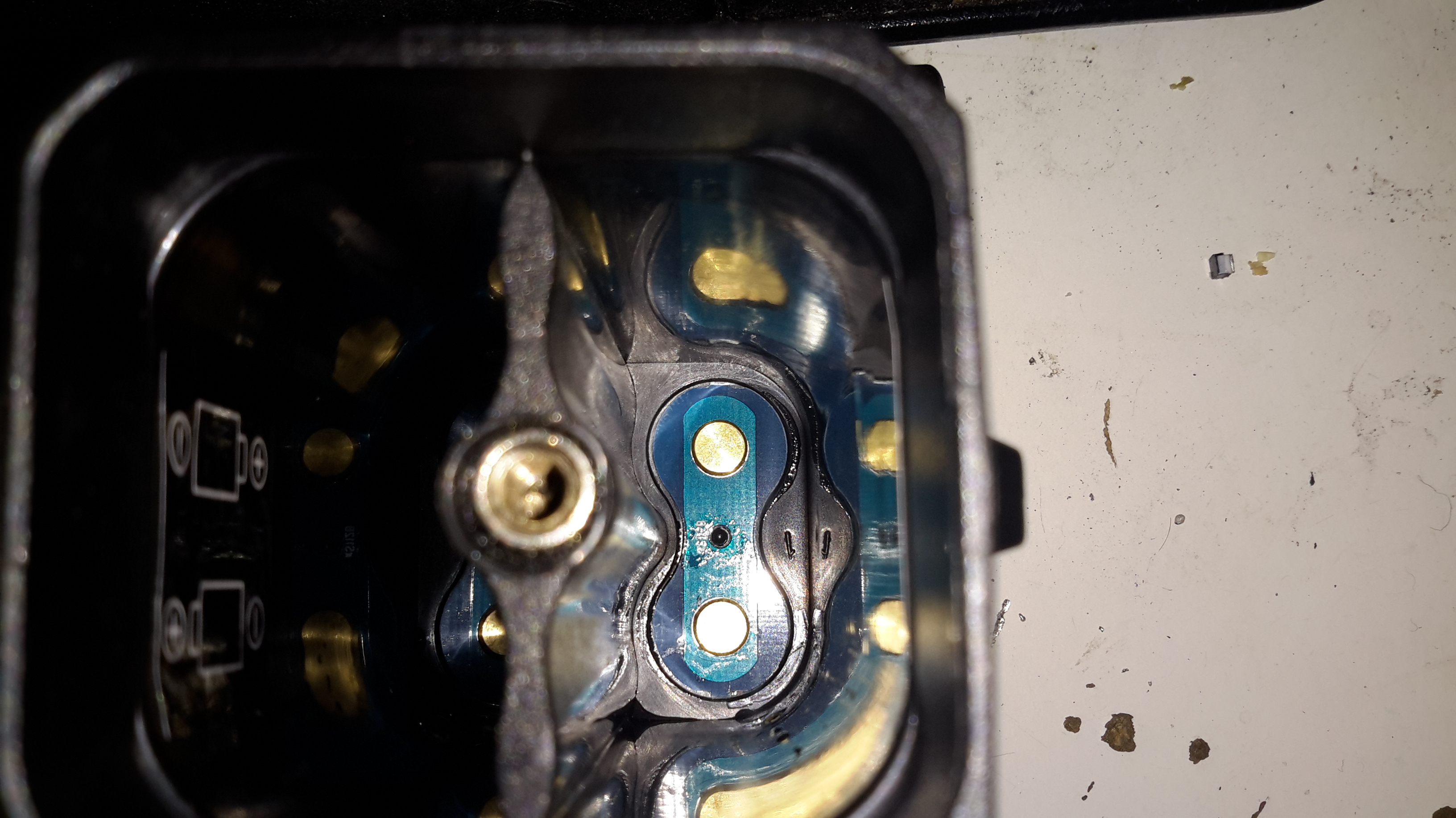
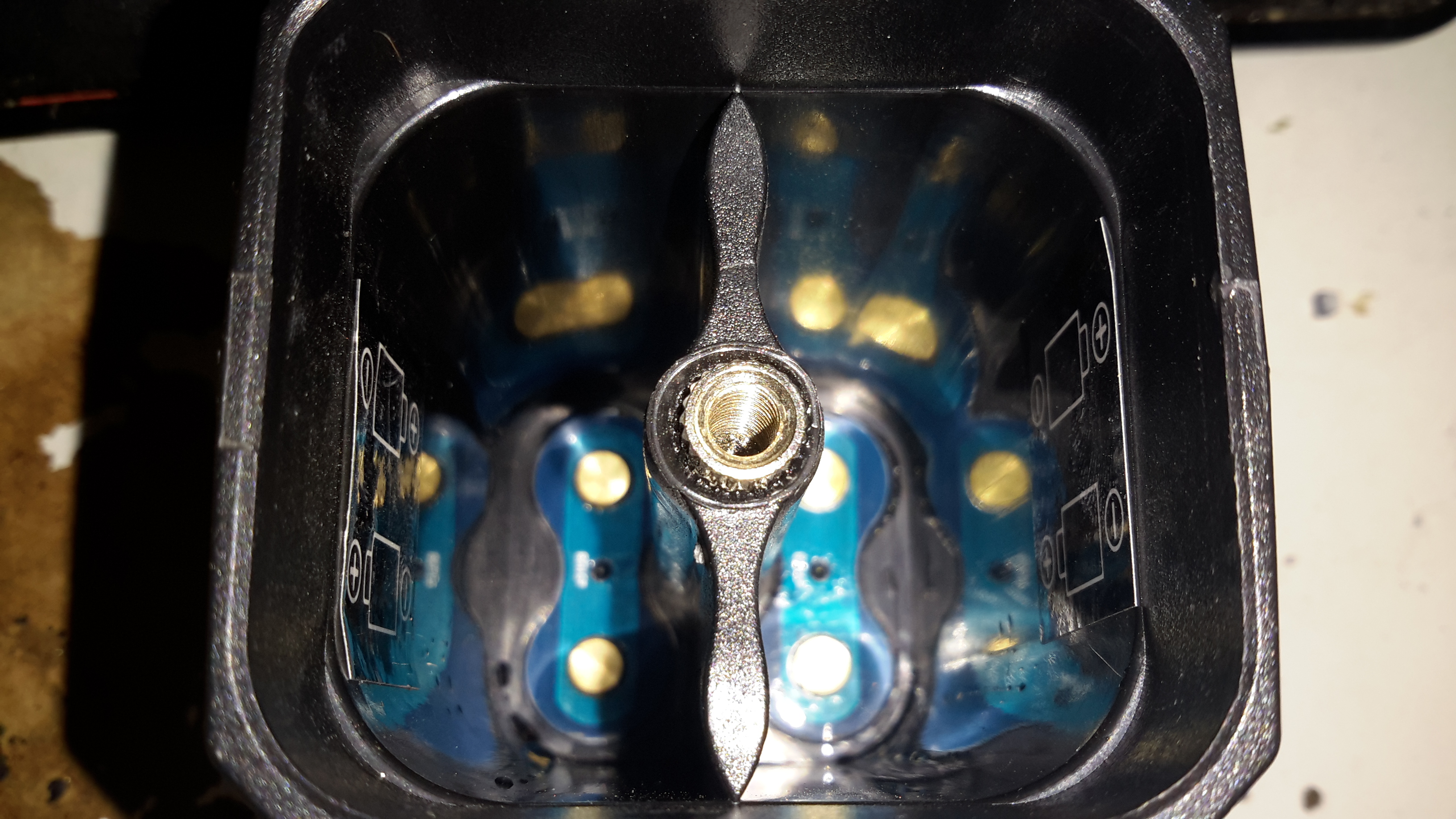
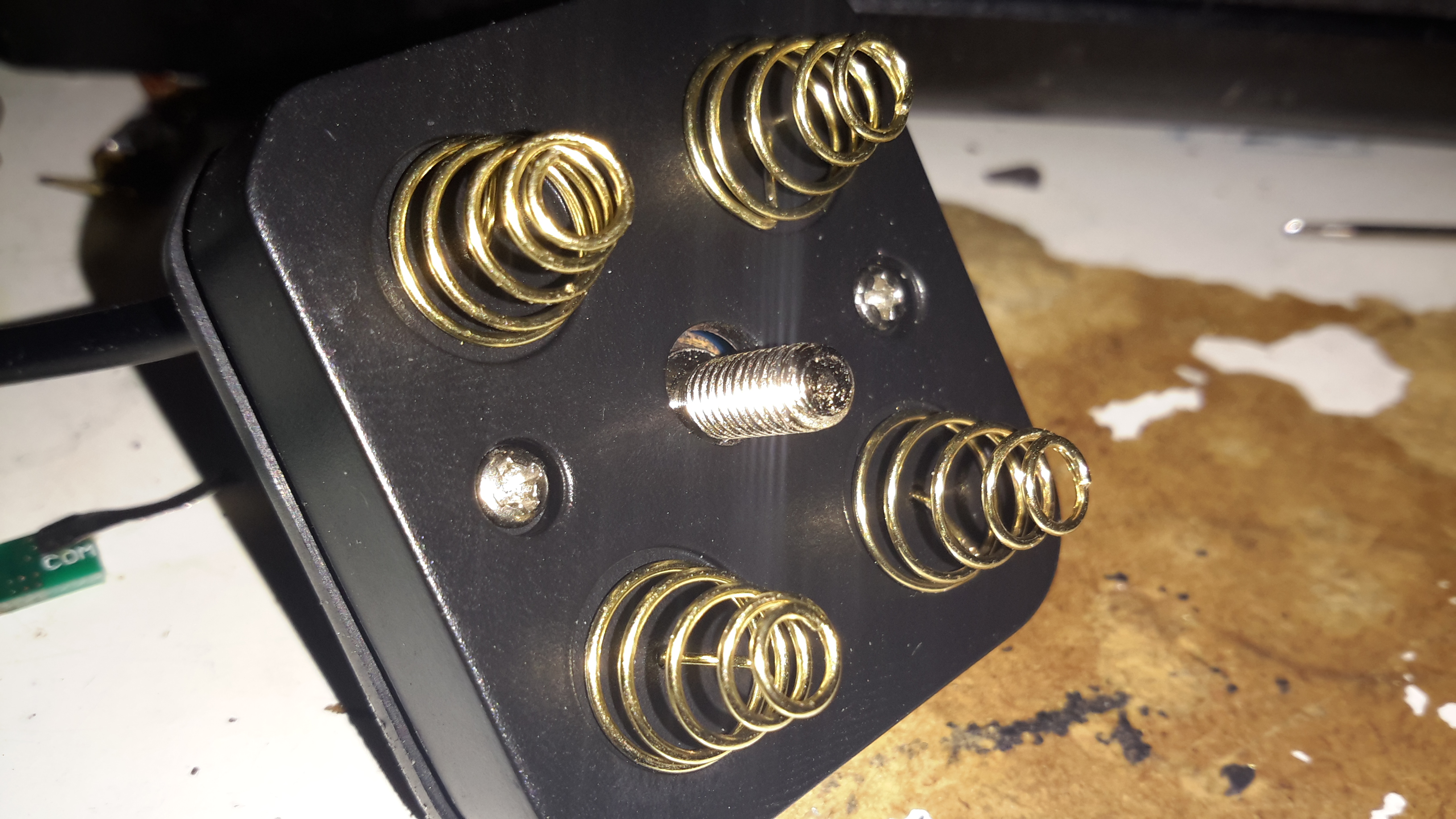
Bottom Cover Removed
Removing the 6 screws on the bottom of the casing allows the board to be seen. Not much on the bottom, the 4 cell negative connections can be seen, with their springs for adjusting for cell length.
MOSFETs
There’s a couple of P-Channel FETs on the bottom side for the charging circuits, along with some diodes.
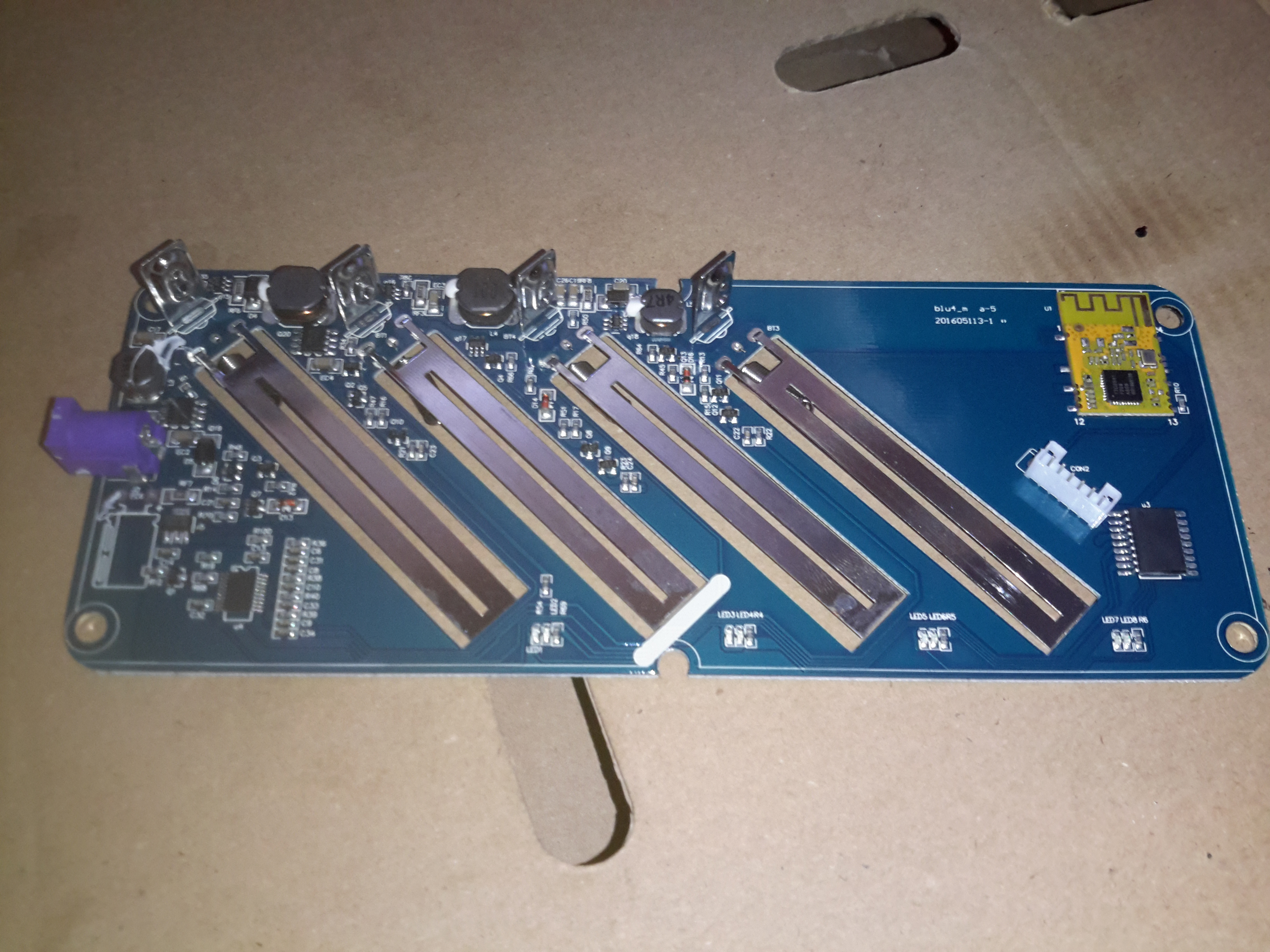
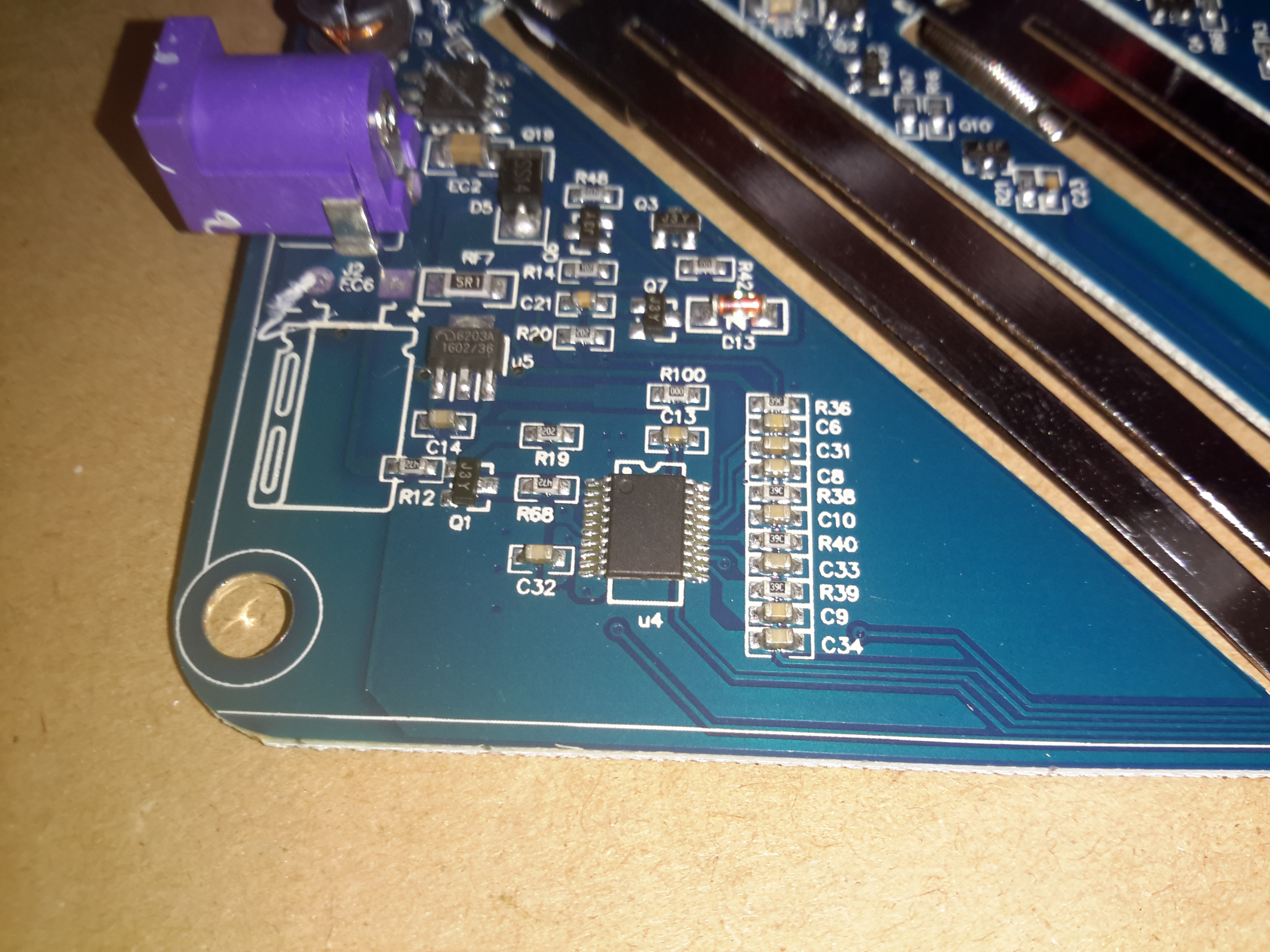
Main PCB
The main PCB is easily removed after the springs are unhooked from the terminals. Most of the power circuitry is located on the top side near the power input. There are 4 DC-DC converters on board for stepping the input 12v down to the 4.2v required to charge a lithium cell.
Second Controller
Not entirely sure what this IC is in the bottom corner, as it’s completely unmarked. I’m guessing it’s a microcontroller though.
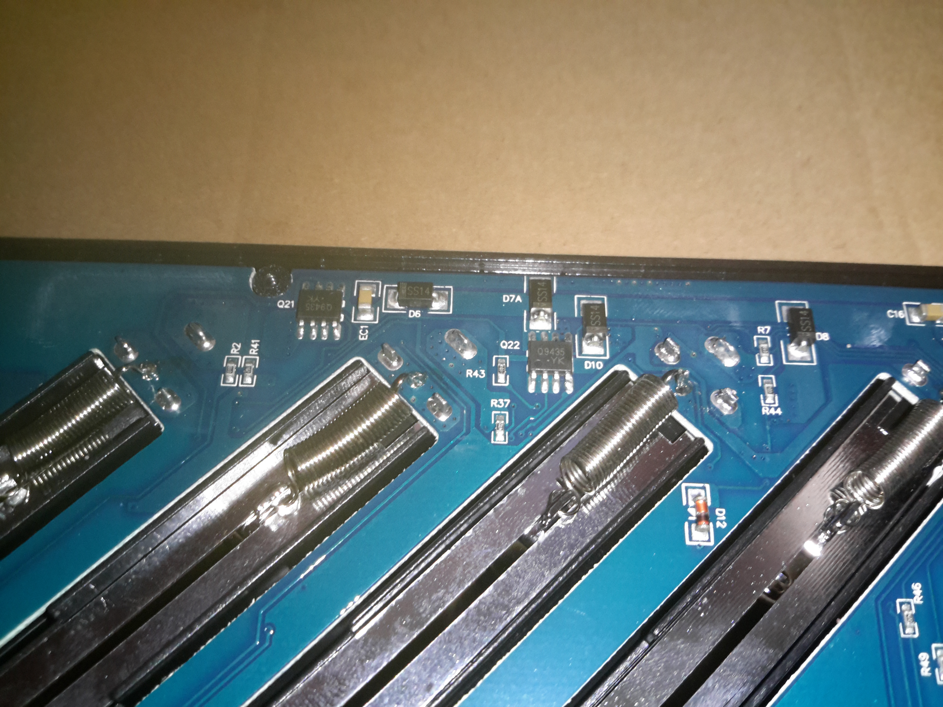
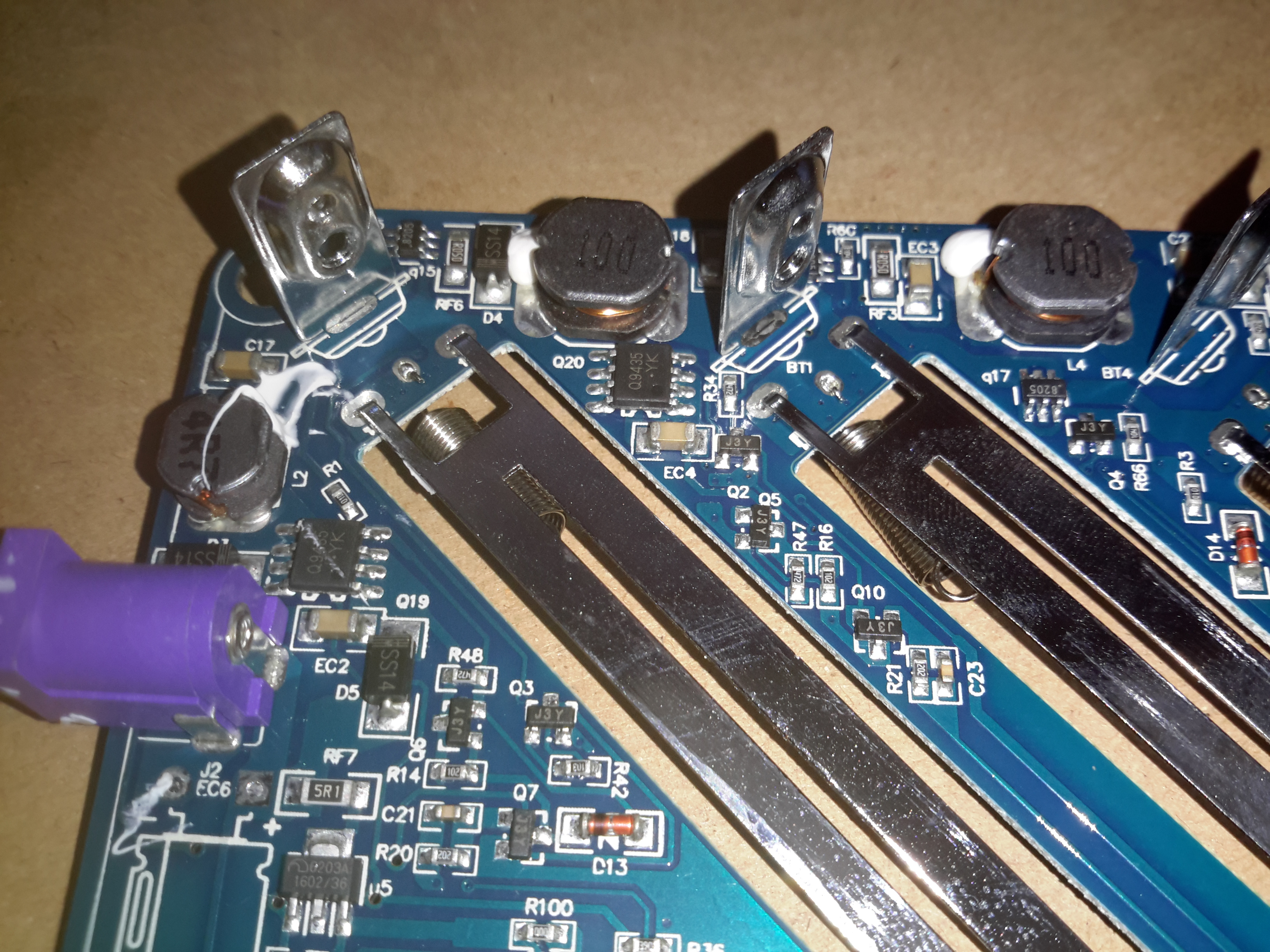
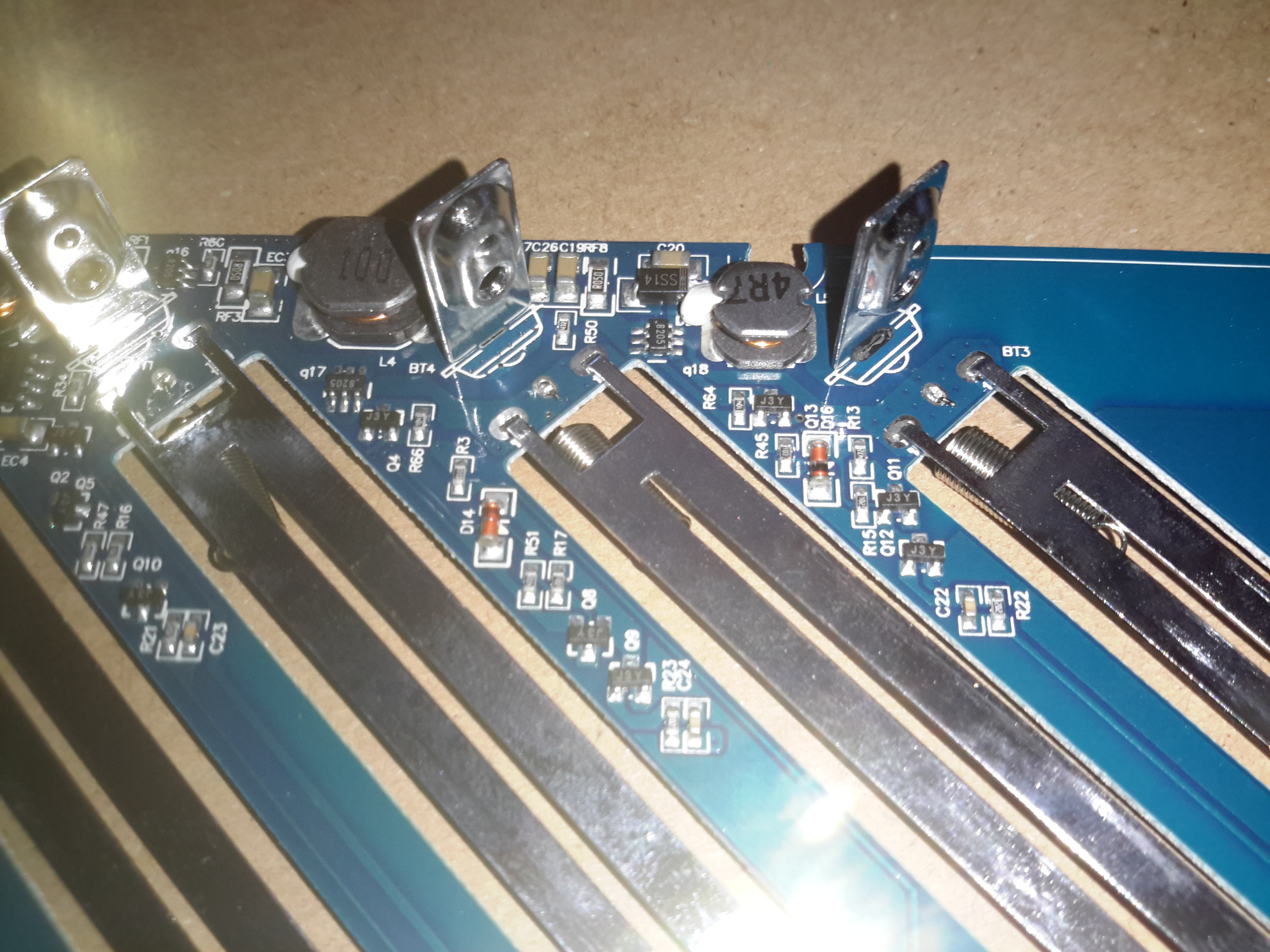
DC Input Side
The top left of the board is crammed with the DC-DC converters, all the FETs are in SO8 packages.
DC-DC Converters
One pair of DC-DC inductors is larger than the other pair, for reasons I’m unsure of.
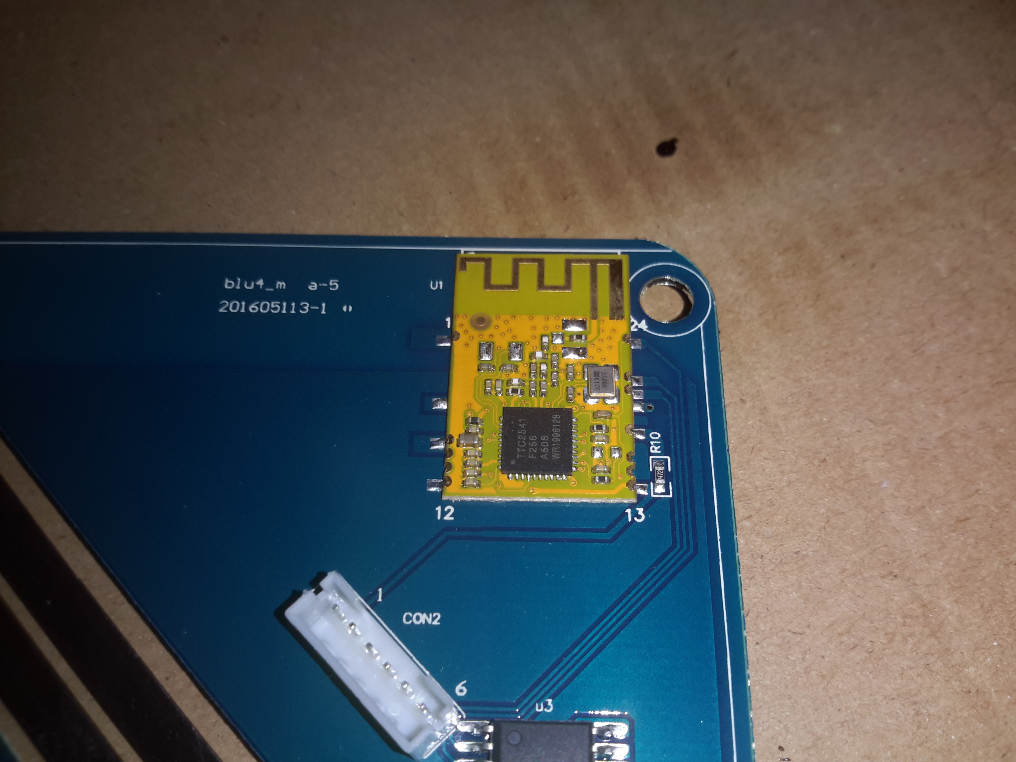
Bluetooth Module
Bluetooth connectivity is provided by this module, which is based around a TTC2541 BLE IC.
Microcontroller
Below the Bluetooth module is yet another completely unmarked IC, the direct link to the BLE interface probably means it’s another microcontroller. The Socket to the left of the IC is the connector for the front panel LCD & button.
LCD PCB
There’s not much to the LCD itself, so I won’t remove this board. The LCD controller is a COB type device, from the number of connections it most likely communicates with the micro via serial.
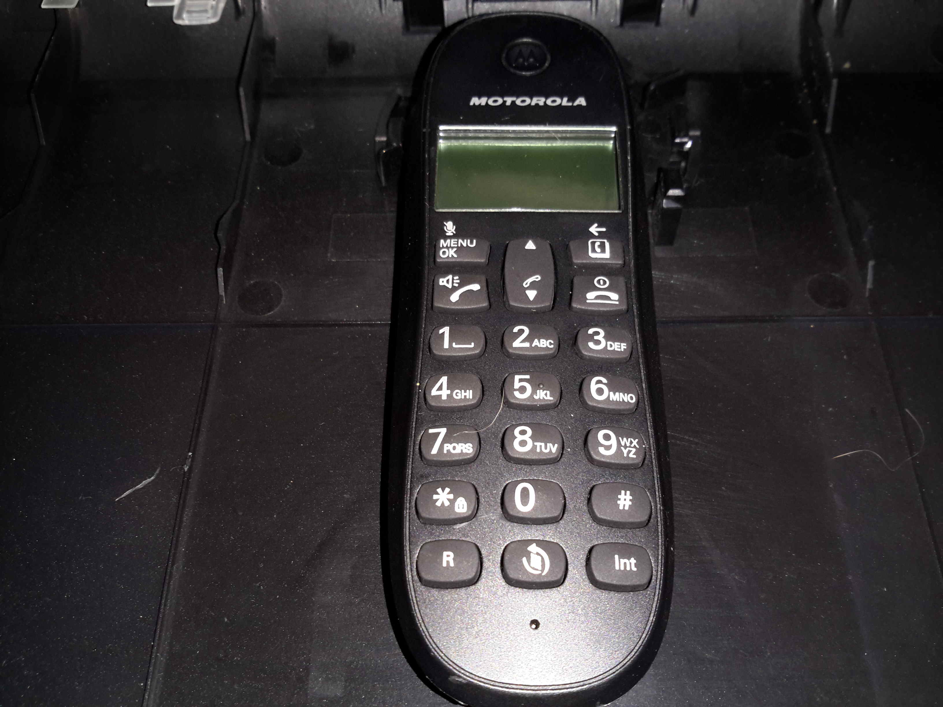
Another random teardown from the junk box time!
Here’s an old Motorola DECT landline phone, no use to me as I’ve not used a landline for many years.
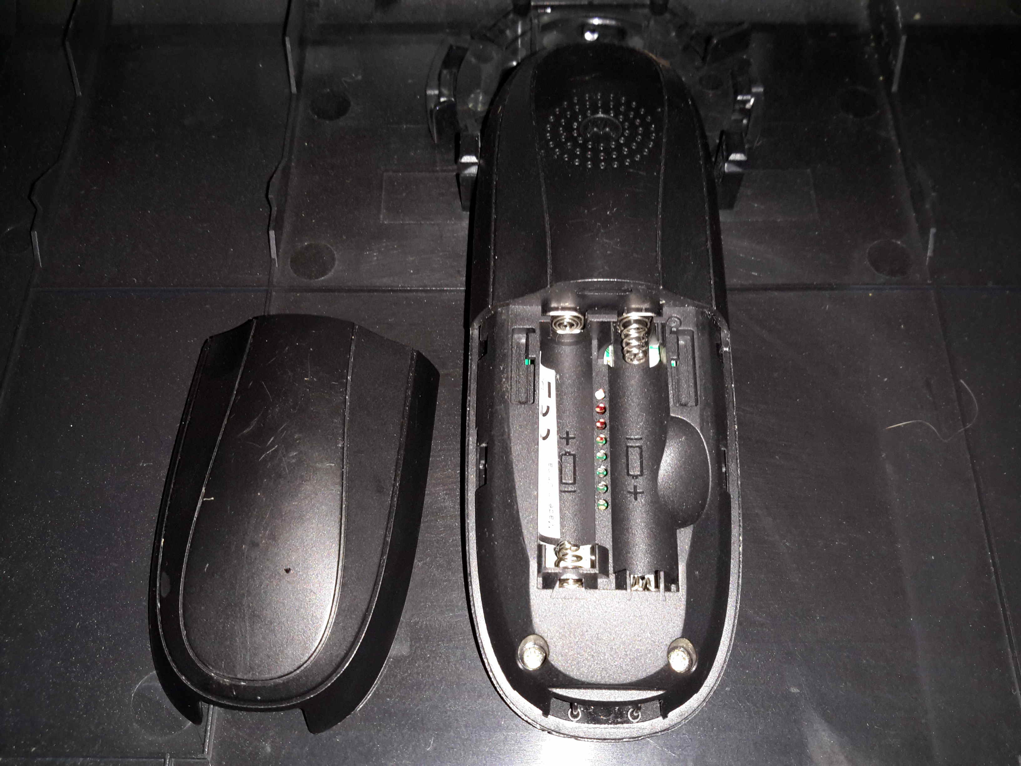
Battery Compartment
Not much on the back, other than the battery compartment for a pair of AAA rechargables. The base unit contains the charger.
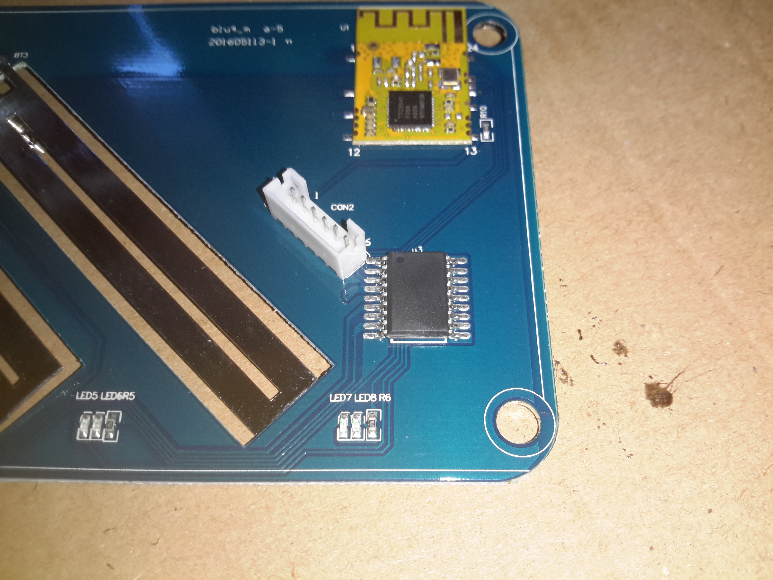
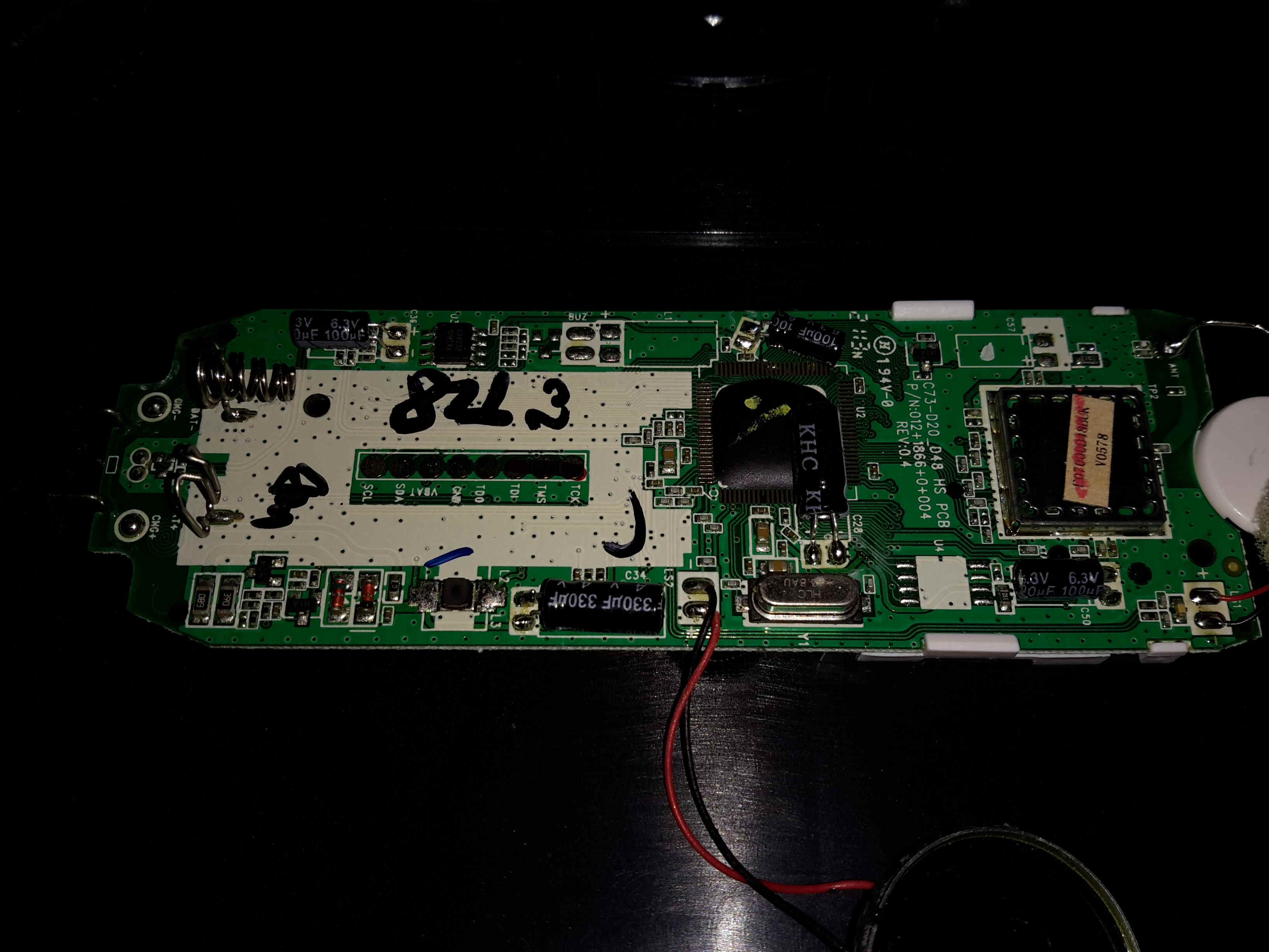
Main PCB
Here’s the main PCB removed from it’s casing. There’s not really much going on, one of the main ICs, which is probably a microcontroller, is a COB device, so no part numbers from there. There’s a row of pads for programming the device at the factory. The RF section is on a dedicated IC, a DE19RF19ZCNC from DSP Group. I couldn’t find much on this part, but it’s one of a range of DECT/VoIP DSP devices.
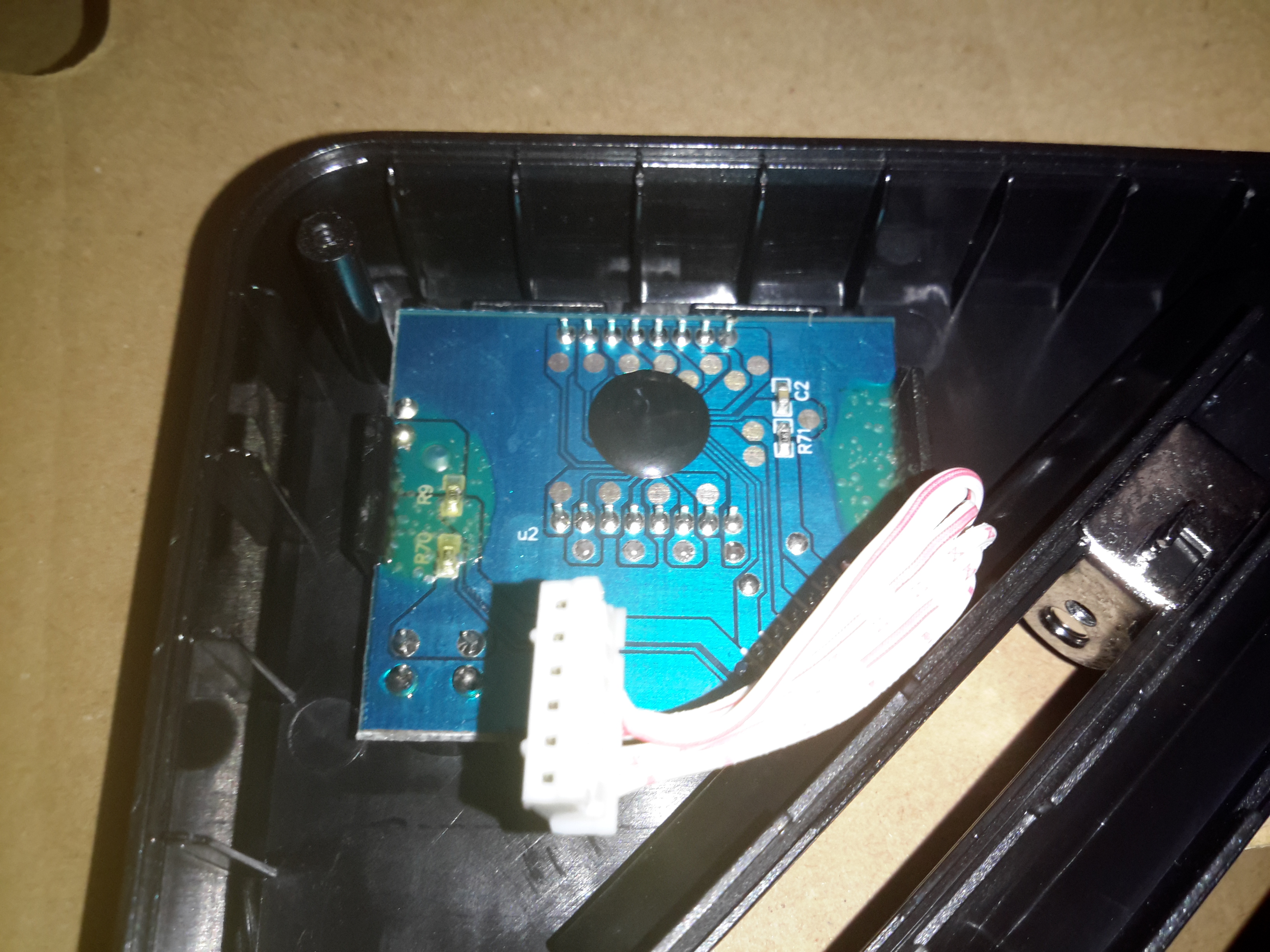
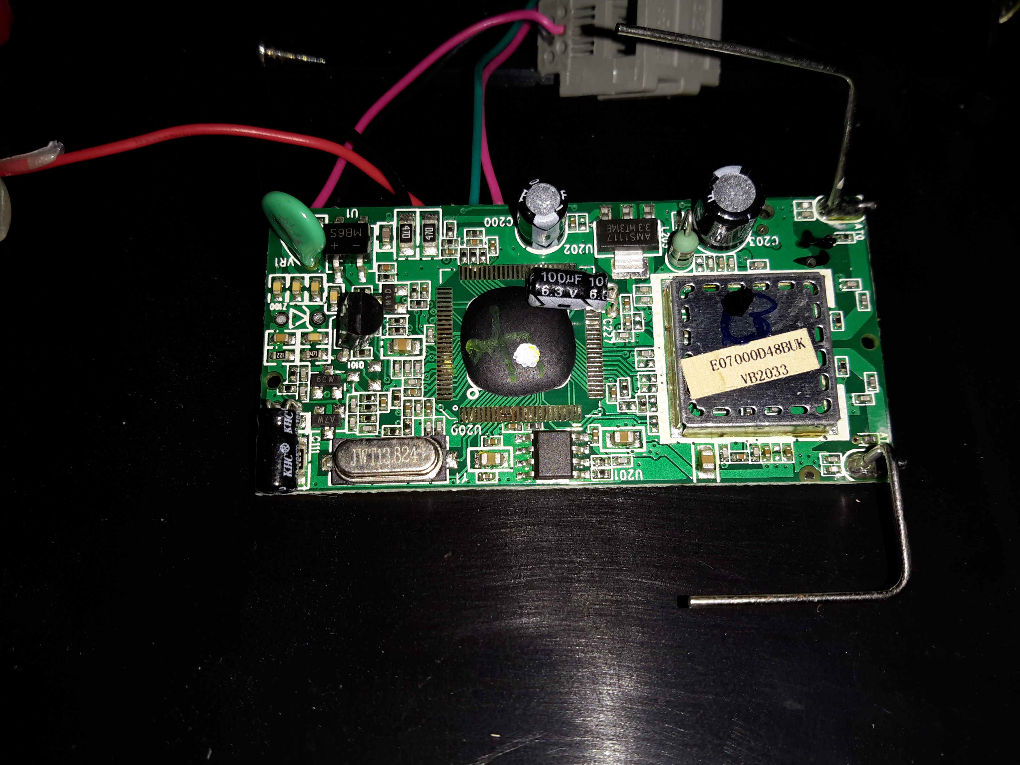
Base Unit PCB
Inside the base unit is a similar board, just without the keypad. Main microcontroller is again a COB device, the RF IC is under the shield.
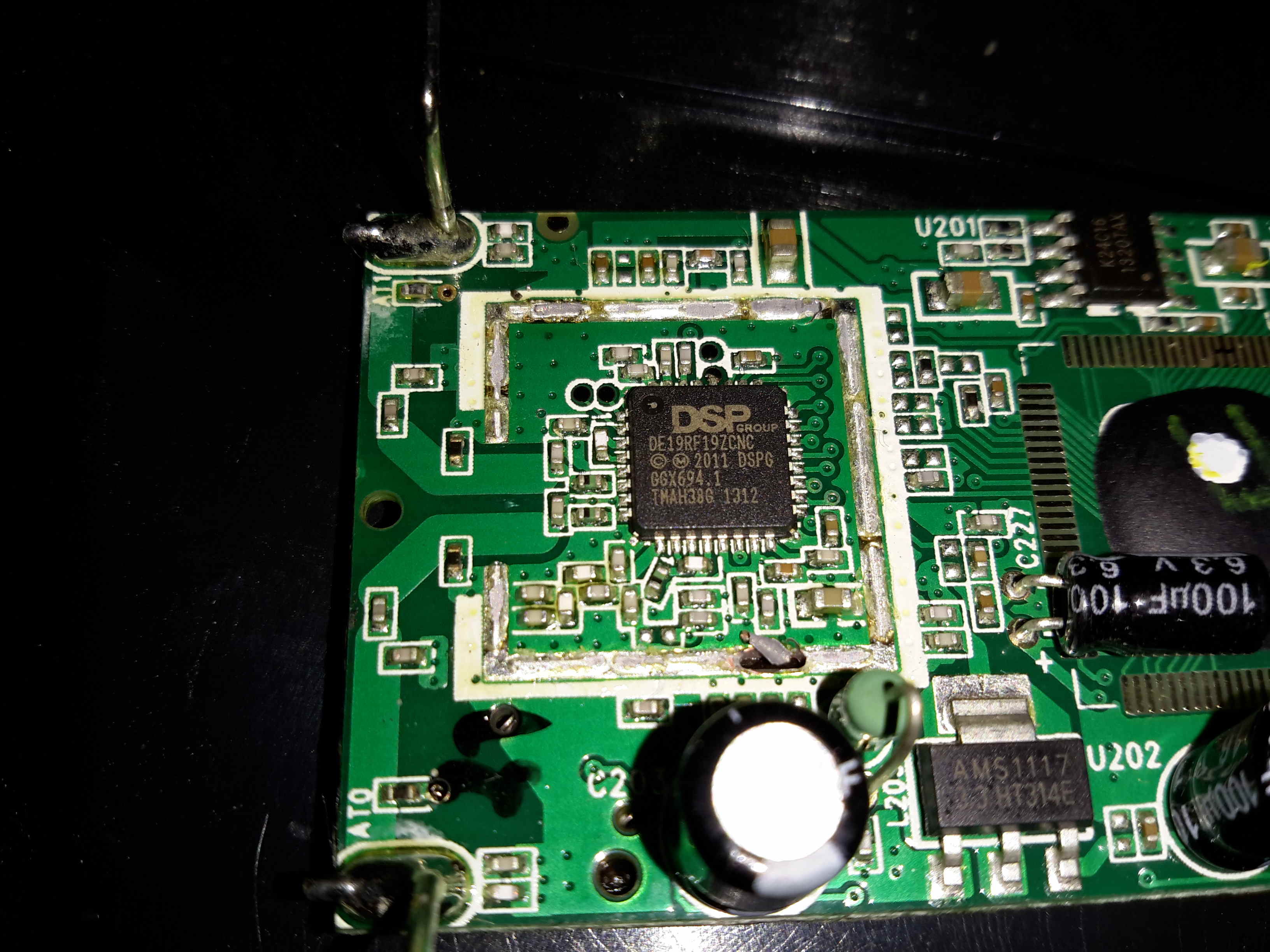
Main Chipset
Removing the shield reveals the same IC as in the handset, only this PCB has a pair of antennas.
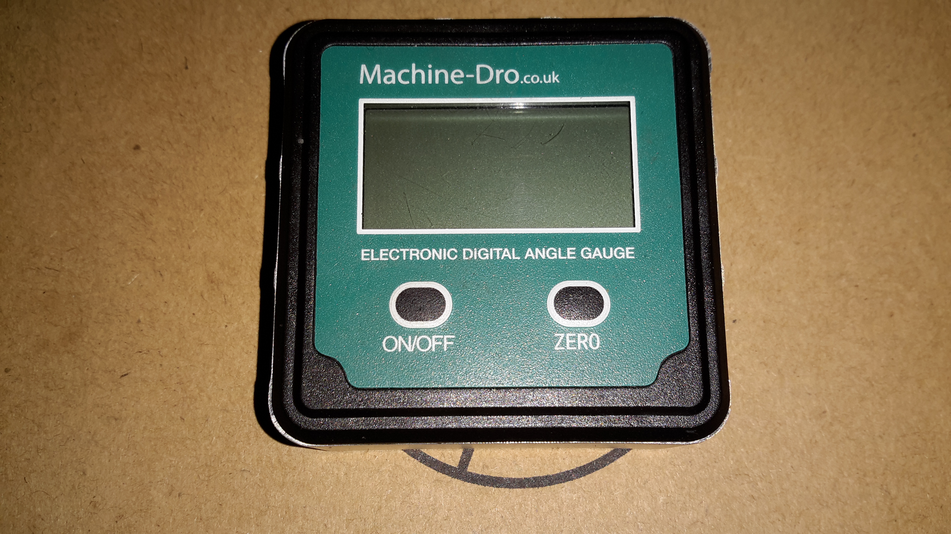
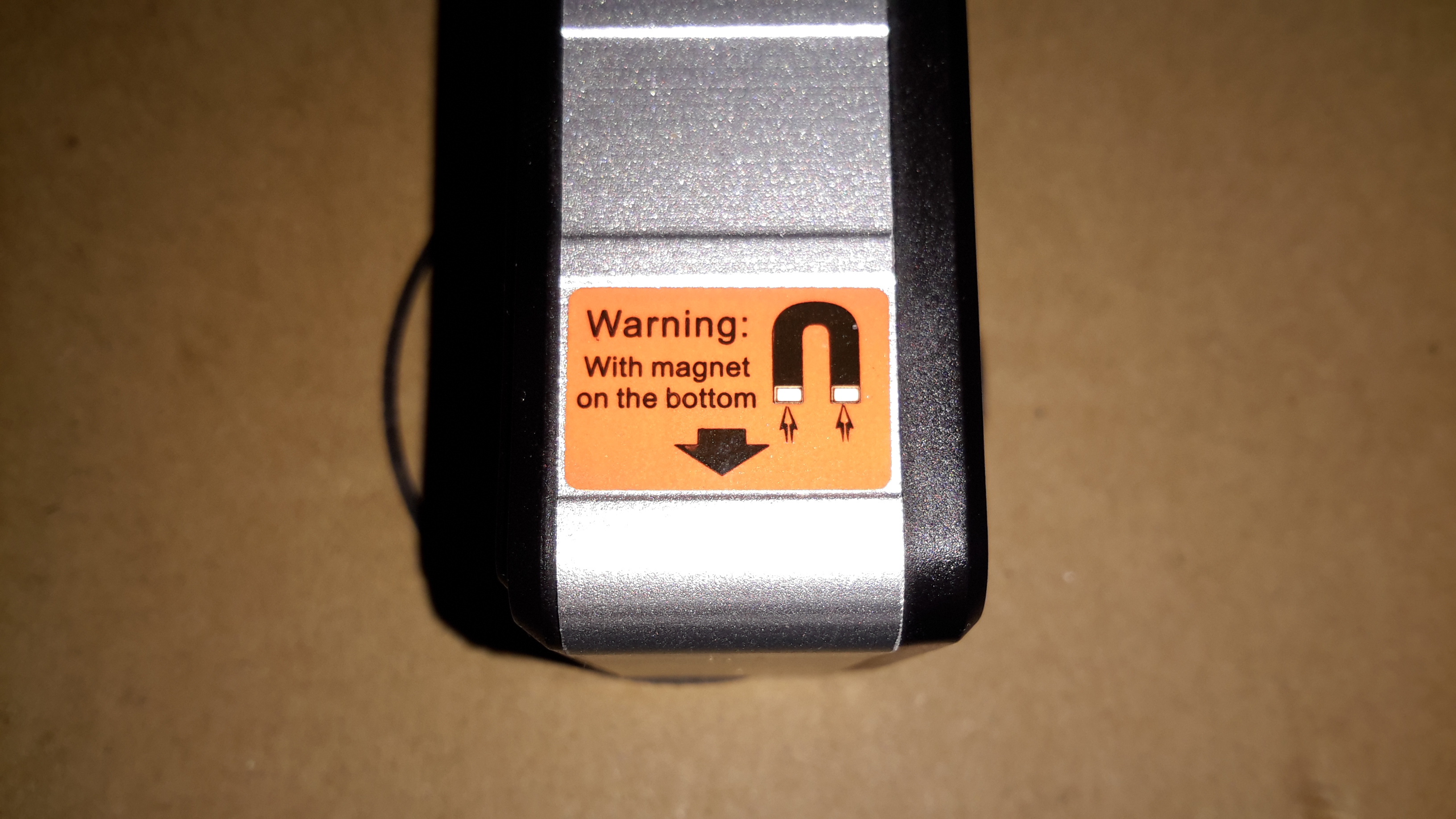
Here’s a useful tool for the kit, a digital angle gauge/protractor. These use a silicon sensor to show the number of degrees the unit is out of level.
Magnets!
Magnets are provided in the base, so the tool can attach to any ferrous surface.
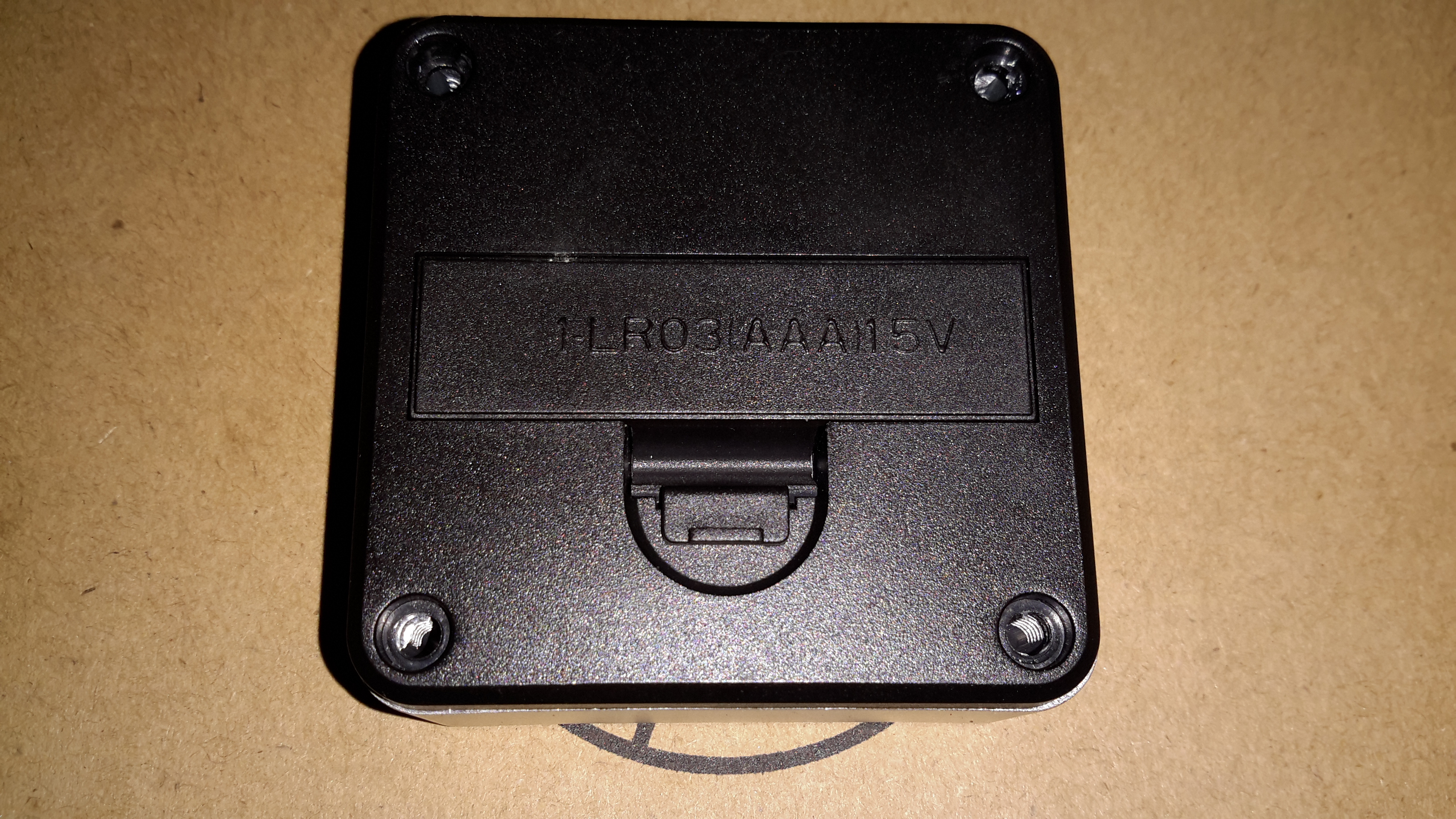
Battery Box
Power is provided by a single AAA cell.
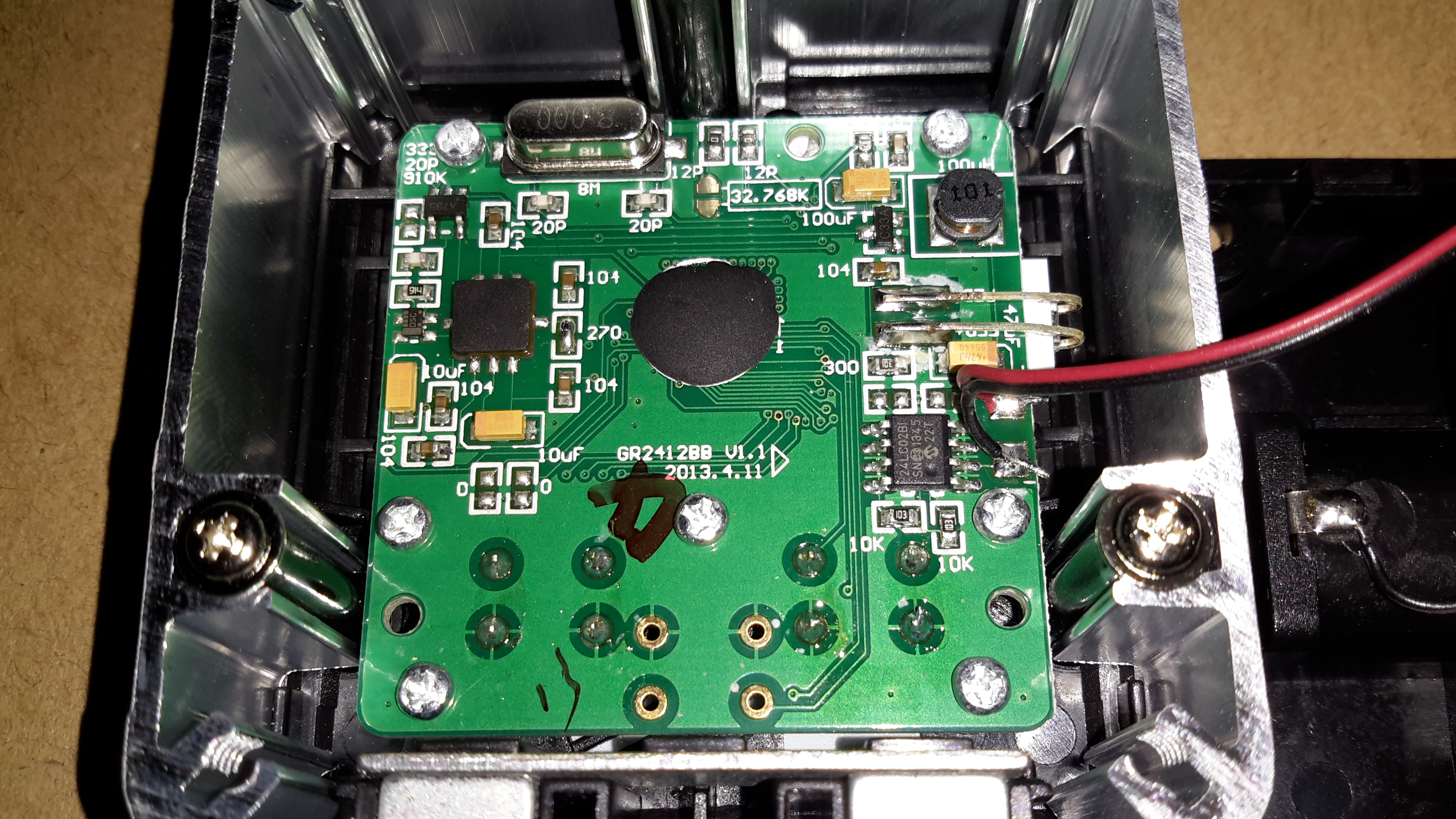
Main PCB
Removing the rear cover reveals the brains of the unit, and there’s not much to it at all. The main microcontroller is a CoB-type device, so no part numbers available from that one.
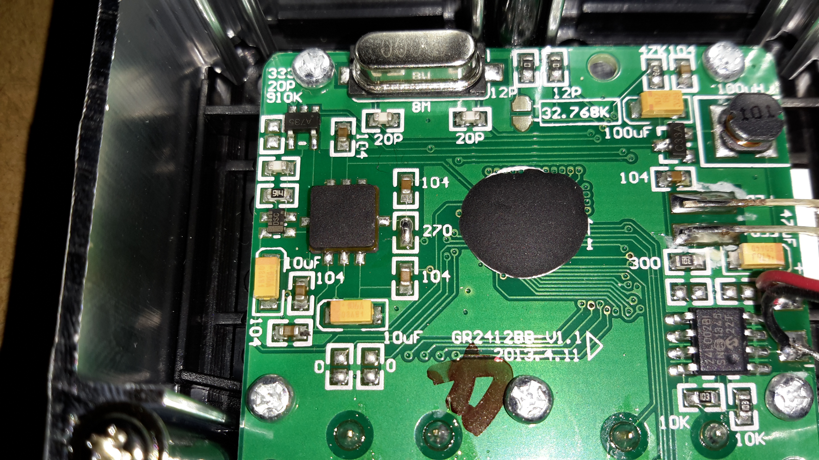
Sensing Element
The IC to the left of the main microcontroller is the sensing element. There’s no markings on this inclinometer IC so I’m not sure of the specs, but it will be a 3D-MEMS device of some sort.
Power Supply
The other side of the PCB has the power supply for the logic, and a serial EEPROM, probably storing calibration data.
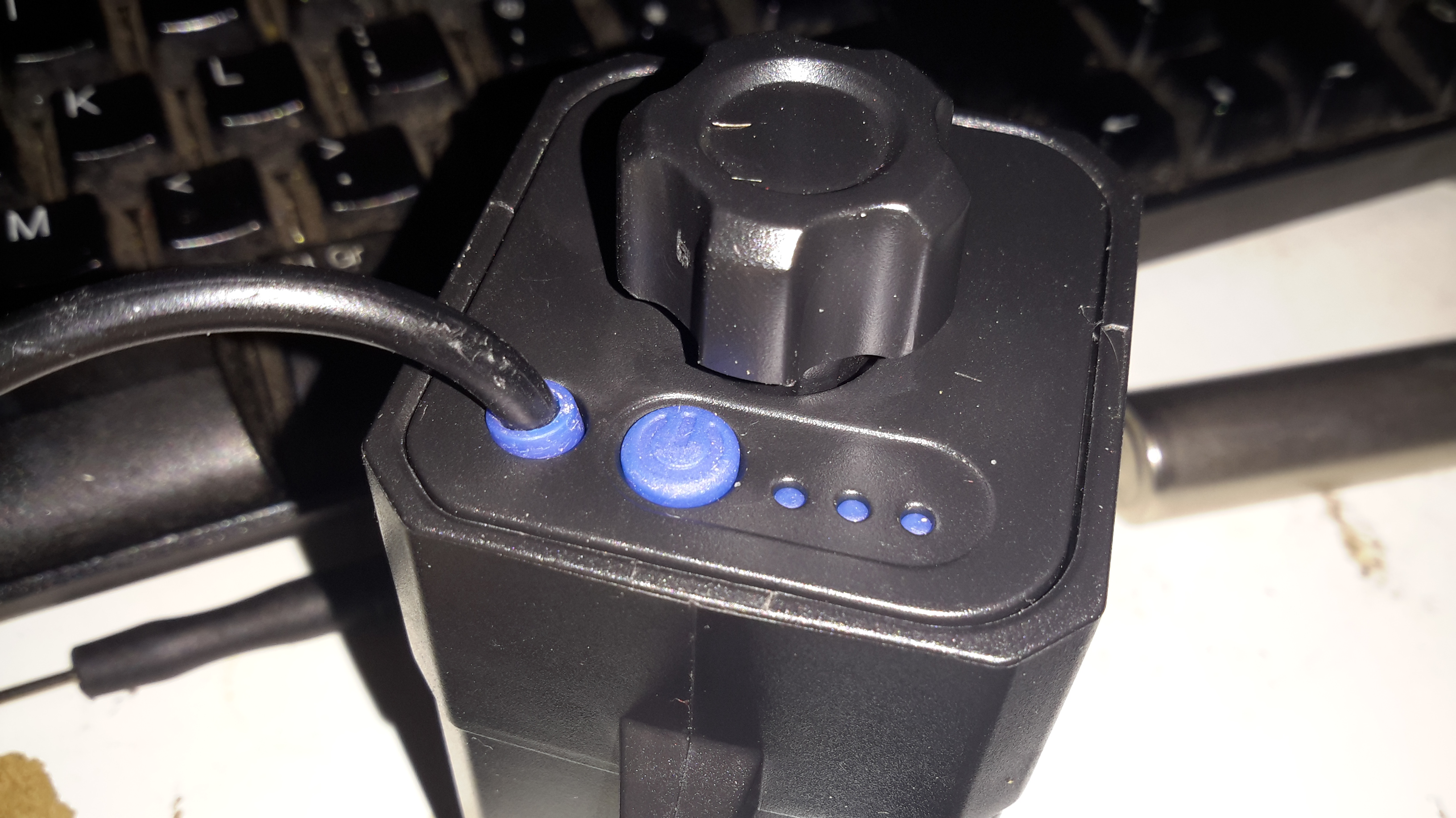
Since the 4×18650 battery pack supplied with my Cree head torch is pretty shit, even by China’s standards, I figured something I could put my own cells into would be a better option. An eBay search turned up these battery boxes, not only with a direct battery output for my torch, but also a USB port for charging other devices when I’m low on charge.
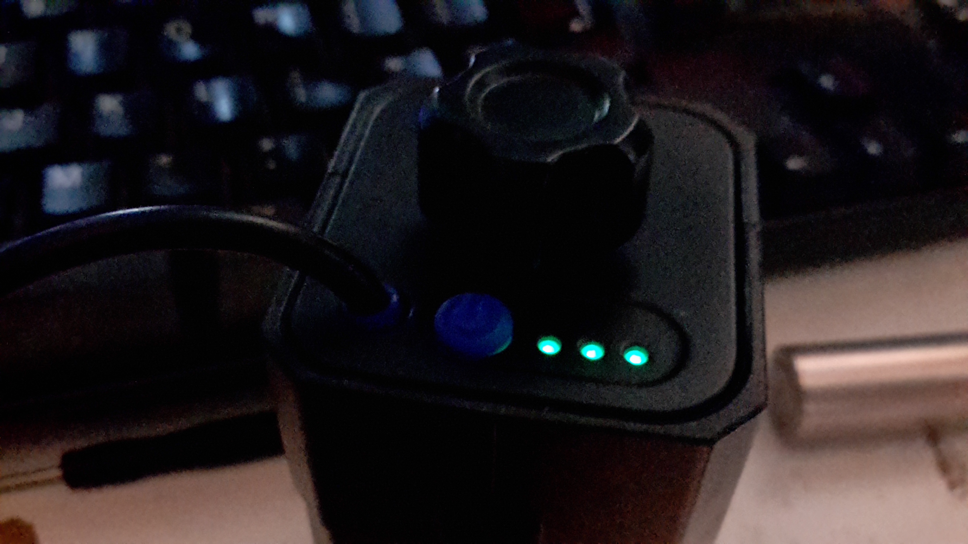
LED Capacity Indicator
The output to the lamp connector is directly connected to the battery, through the usual Lithium Ion protection, but the USB output is controlled from a single power button. Battery charge condition is displayed on 3 LEDs. Not sure why they used blue silicone for the seal & then used green LEDs… But it does work, even if a little dim.
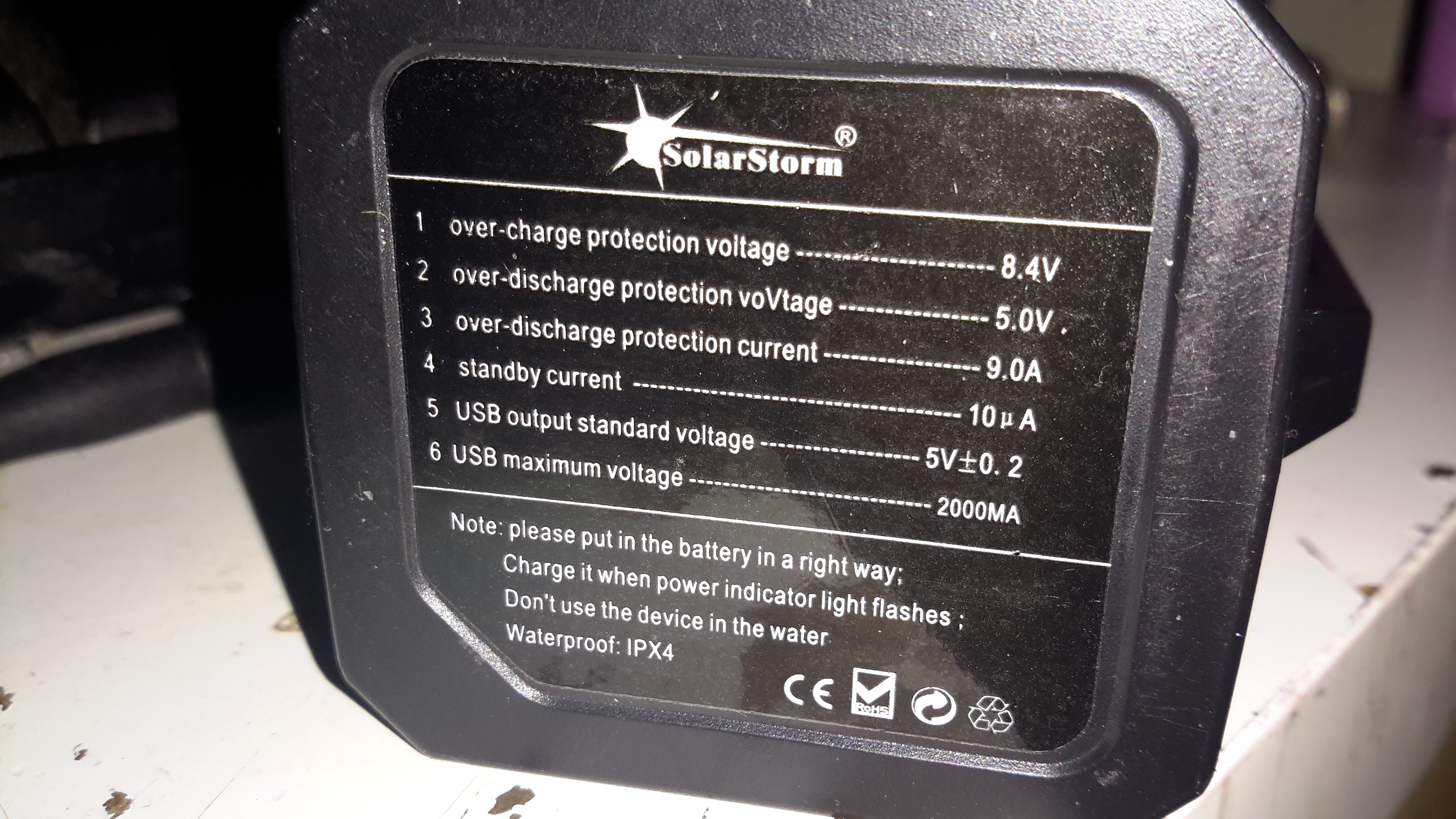
Label
Essential information. Does claim to be protected, and from the already existing electronics for the USB this would be expected in all but the cheapest crap.
An IP rating of IPX4 is claimed, yet just above that rating is a notice not to be used in water. Eh?
This is sealed with an O-Ring around the edge of the top cap & silicone seals around the cable & retaining screw. I did test by immersion in about 6″ of water, and it survived this test perfectly fine, no water ingress at all.
Interconnect Straps
The casing holds a PCB at the bottom end with the cell straps.
Screw Post
Someone wasn’t that careful at getting the brass screw insert properly centred in the injection mould when they did this one. It’s mushed off centre, but i’s solidly embedded & doesn’t present any problems to usability.
Cell Springs
The top cover holds the cell springs & the electronics.
Button & Cable Seal
Removing the pair of screws allows the top cap to open up. The cable, button & LEDs are robustly sealed off with this silicone moulding.
Top Removed
Here’s the PCB, not much on the top, other than the power button & battery indicator LEDs.
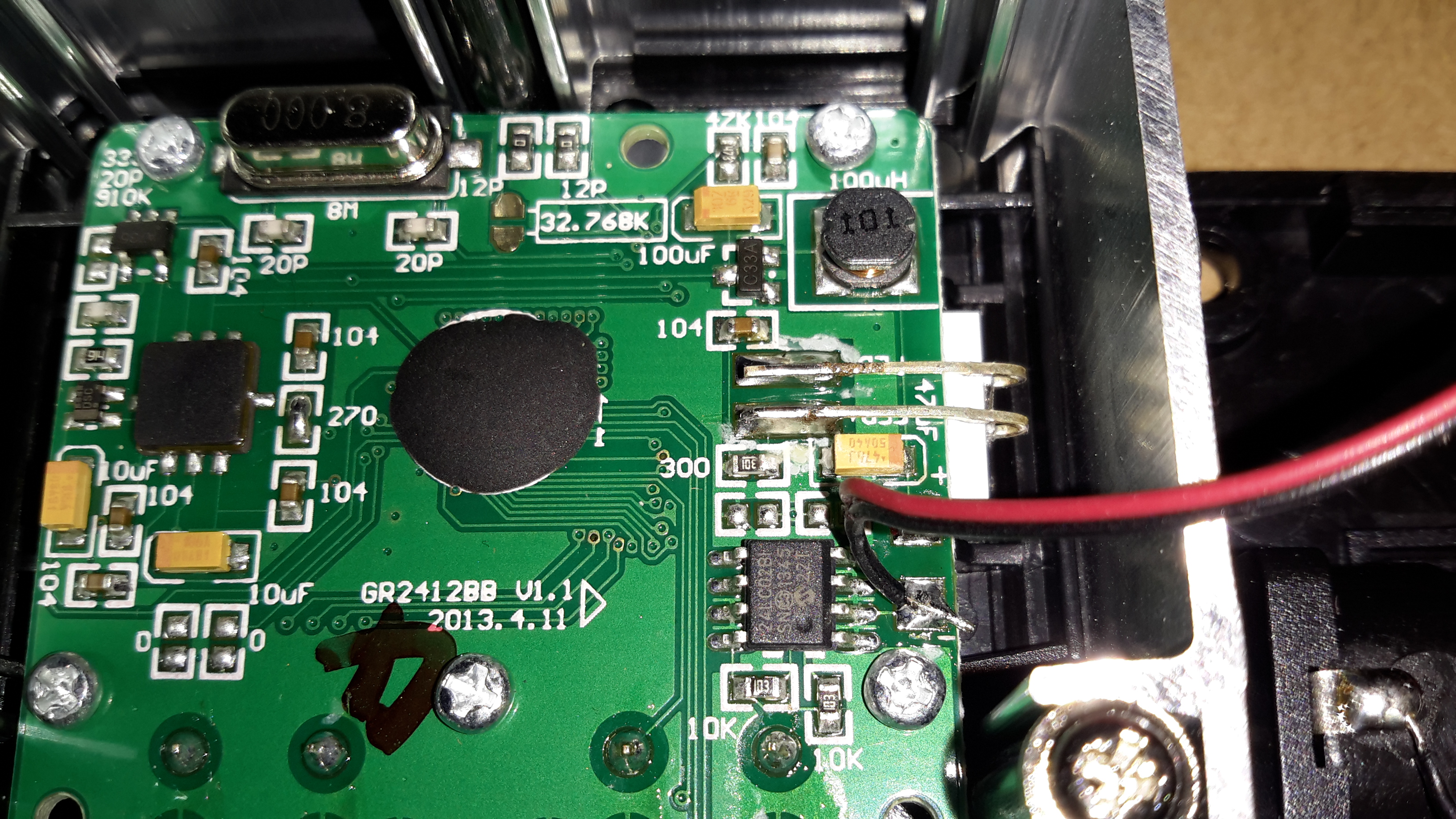
Electronics
Desoldering the cell springs allows the PCB to pop out of the plastic moulding. There’s more than I expected here!
Bottom left is a DC-DC converter, generating the +5v rail for the USB port, this is driven with an XL1583 3A buck converter IC.
Bottom right is the protection IC & MOSFETs for the Lithium Ion cells. I wasn’t able to find a datasheet for the tiny VA7022 IC, but I did manage to make certain it was a 7.4v Li-Ion protection IC.
Top right is a completely unmarked IC, and a 3.3v SOT-23 voltage regulator. I’m assuming that the unmarked IC is a microcontroller of some sort, as it’s handling more than just the battery level LEDs.
A pretty decent 4-core cable finishes the job off. For once there’s actually some copper in this cable, not the usual Chineseuim thin-as-hair crap.
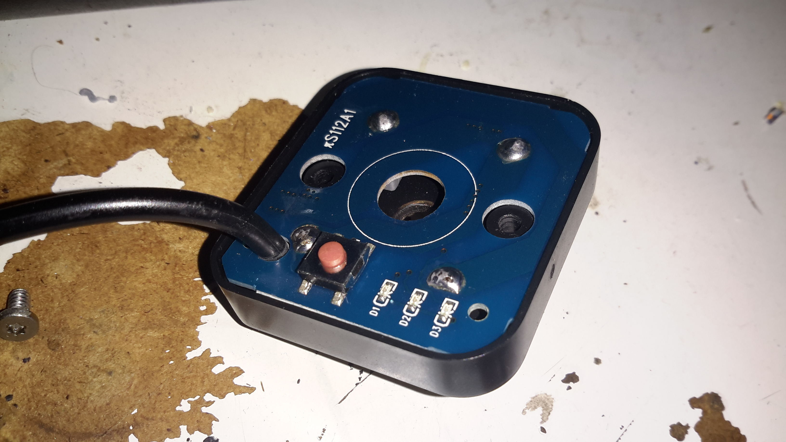
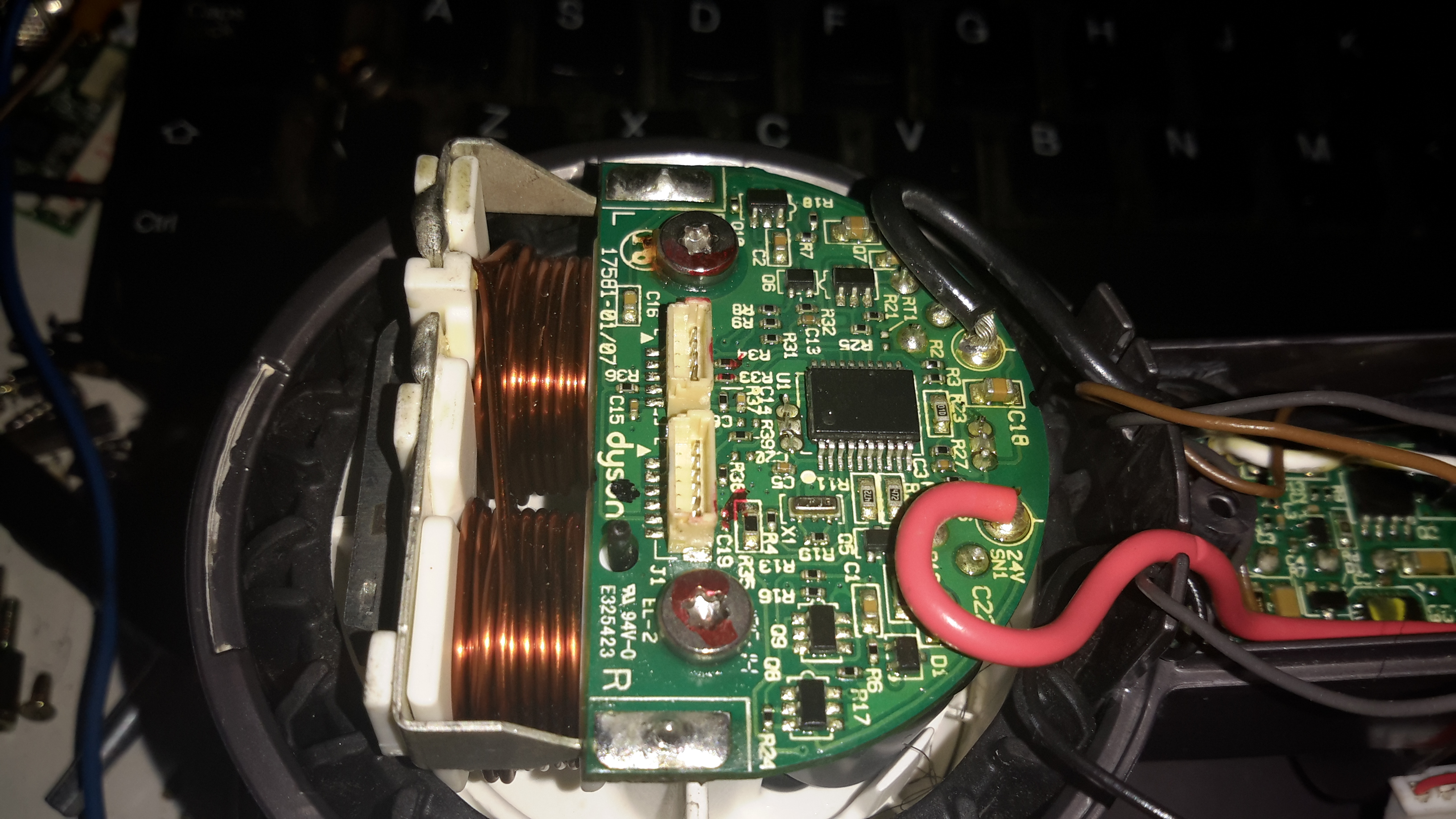
Here’s another Dyson teardown, in my efforts to understand how marketing have got hold of relatively simple technology & managed to charge extortionate amounts of money for it.
This is the DC35, the model after the introduction of the brushless digital motor.
Back Cap Removed
On this version the mouldings have been changed, and the back cover comes off, after removing the battery retaining screw. It’s attached with some fairly vicious clips, so some force is required. Once the cap is removed, all the electronics are visible. On the left is the motor itself, with it’s control & drive PCB. There’s another PCB on the trigger, with even more electronics. The battery connector is on the right.
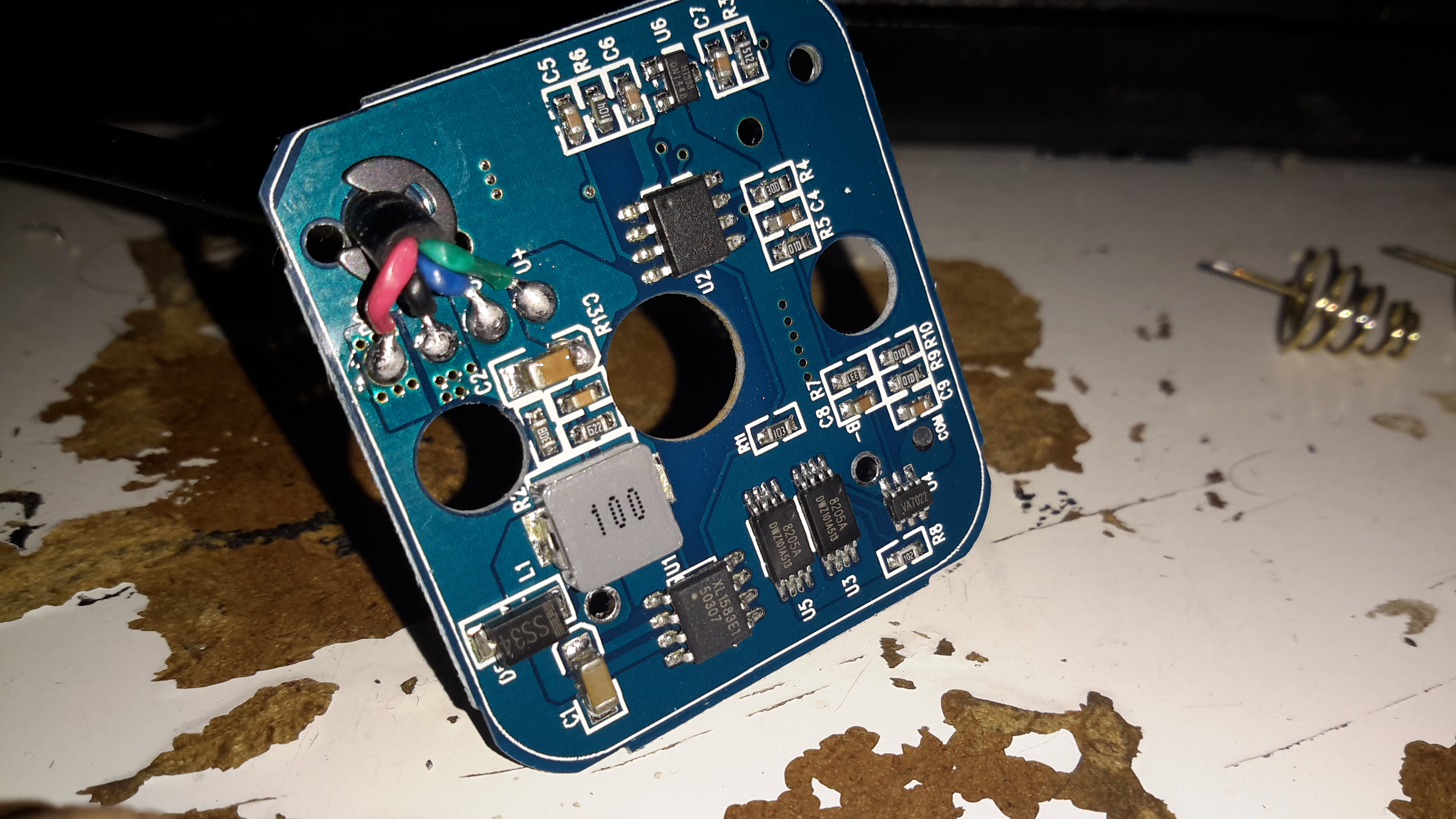
Trigger PCB
Here’s the trigger PCB, which appears to deal with DC-DC conversion for powering the brush attachments. The QFN IC with yellow paint on it is an Atmel ATTiny461 8-bit microcontroller. This is probably controlling the DC-DC & might also be doing some battery authentication.
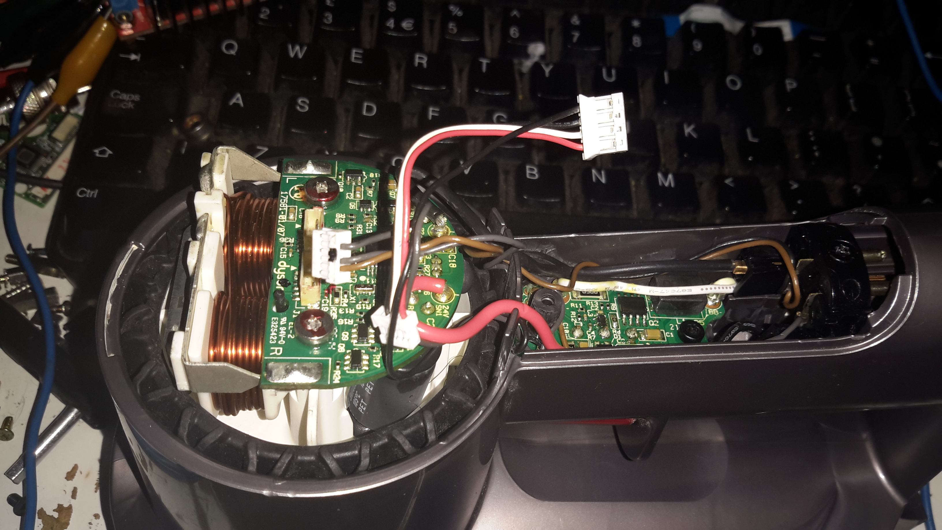
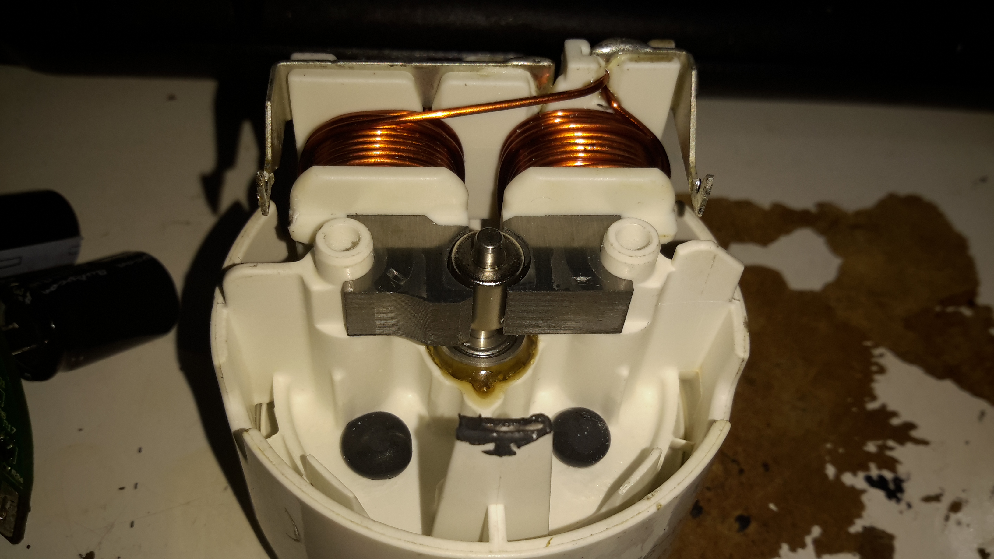
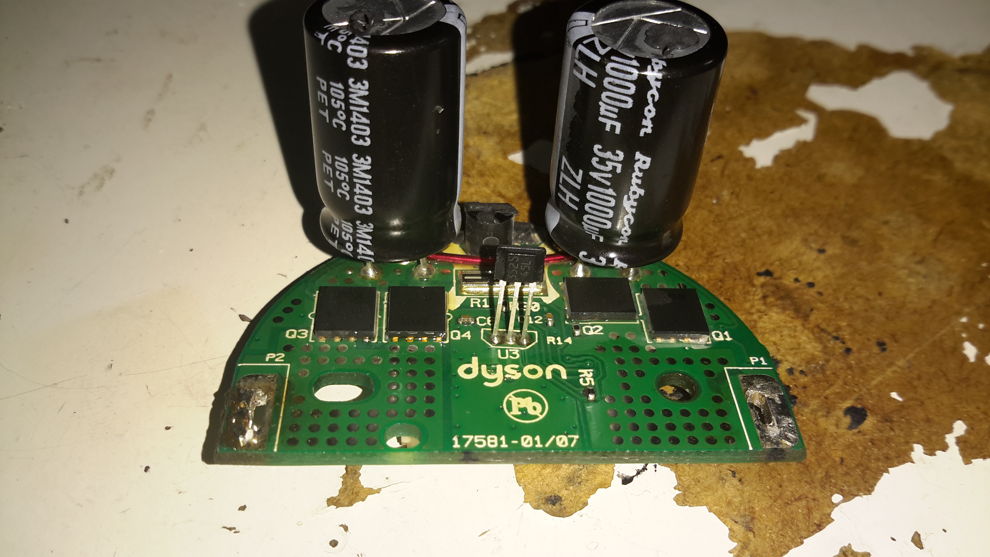
“Digital Motor”
Here’s the motor & it’s board. The windings on the stator are extremely heavy, which makes sense considering it’s rated at 200W. The main control IC is a PIC16F690 from Microchip. Instead of using an off the shelf controller, this no doubt contains software for generating the waveforms that drive the brushless motor. It also appears to communicate with the other PCBs for battery authentication.
Stator
Desoldering the board allows it to be removed from the motor itself. The pair of windings are connected in anti-phase, to create alternating North-South poles depending on polarity. Since the existing controller is unusable due to software authentication with the other parts, I might have a go at building my own driver circuit for this with an Arduino or similar.
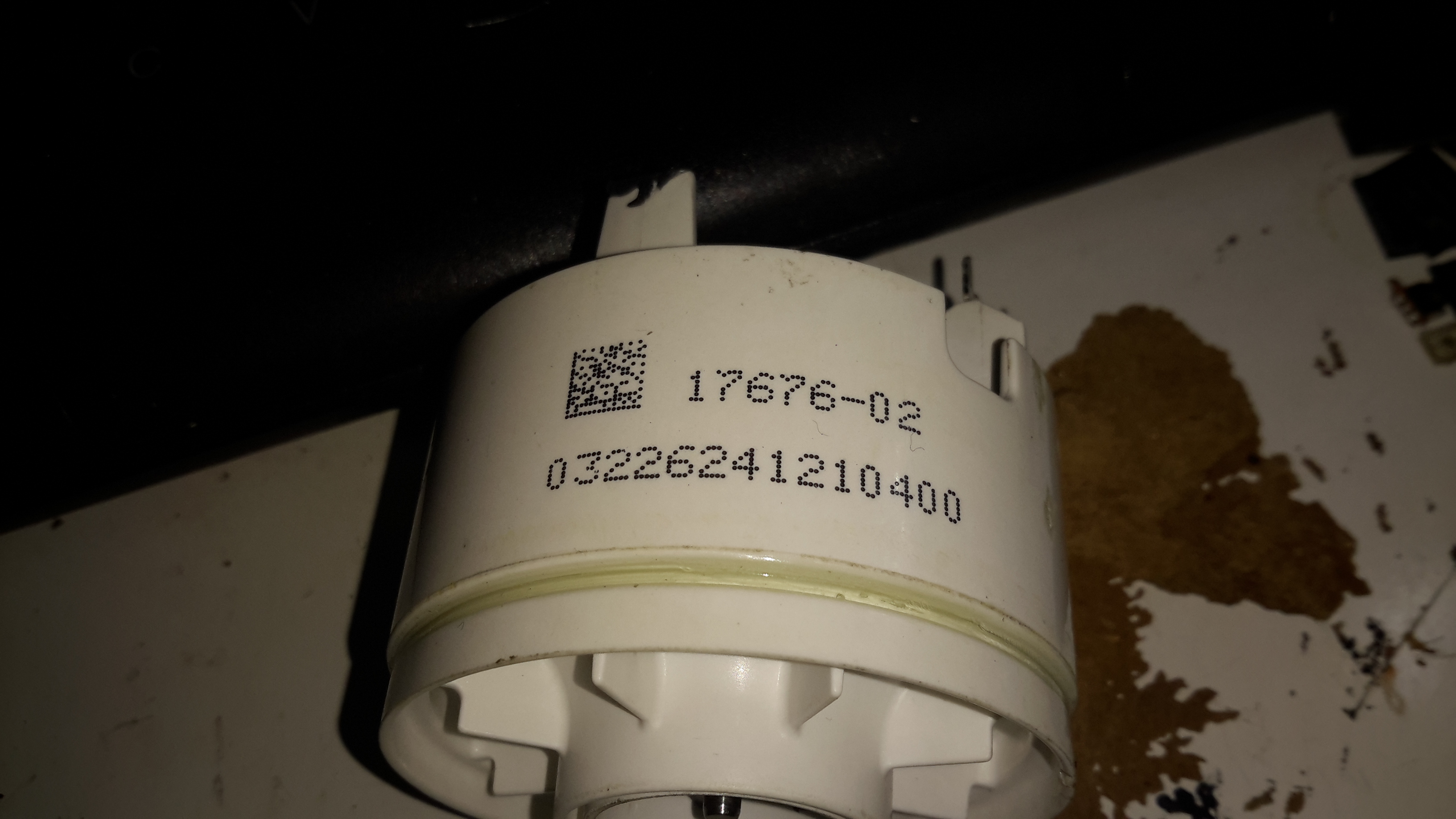
Blower Assembly
The blower assembly is simple plastic mouldings, pressed together then solvent welded at the seam.
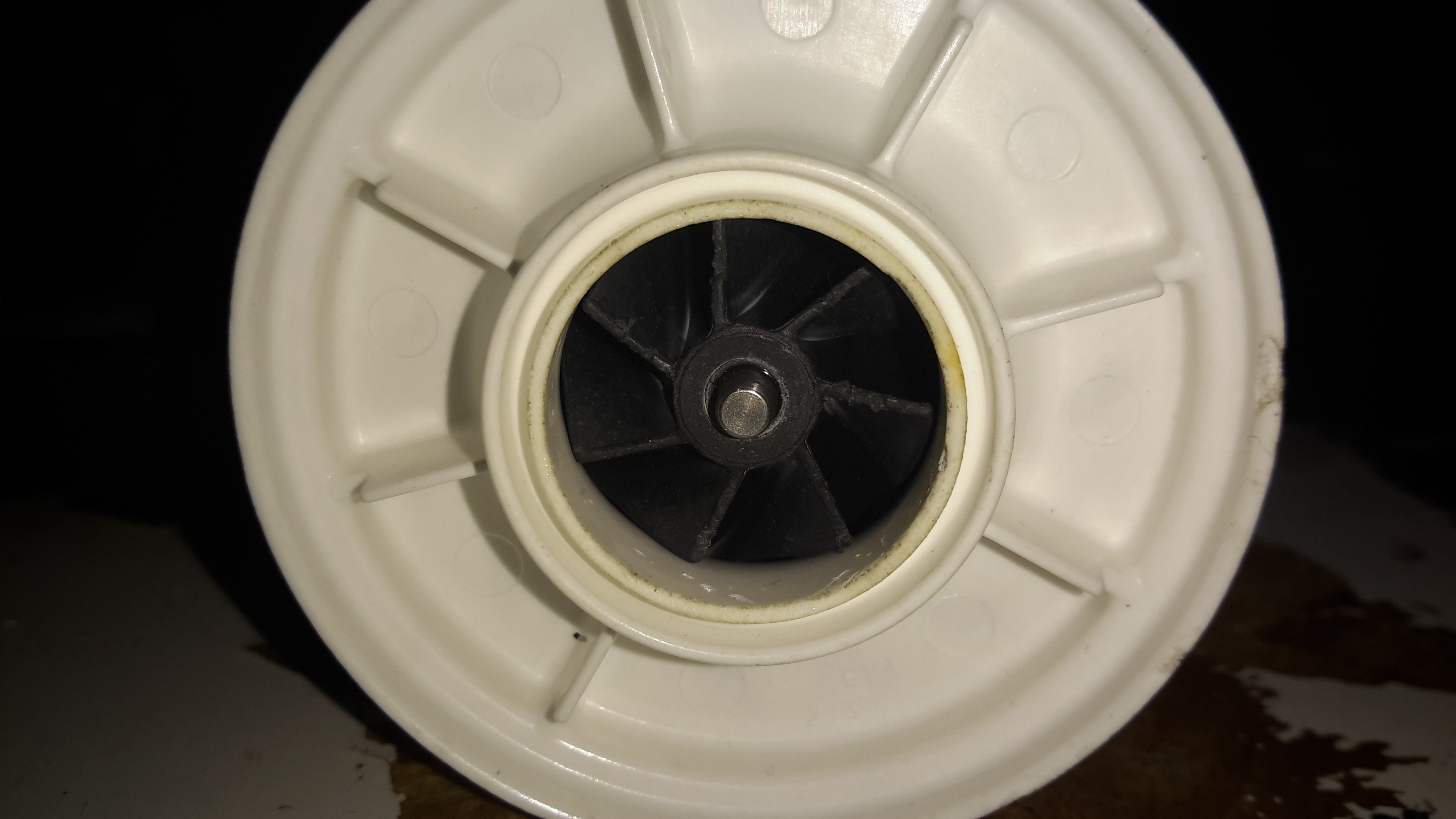
Impeller
The impeller is just a centrifugal compressor wheel, identical to what’s used in engine turbochargers.
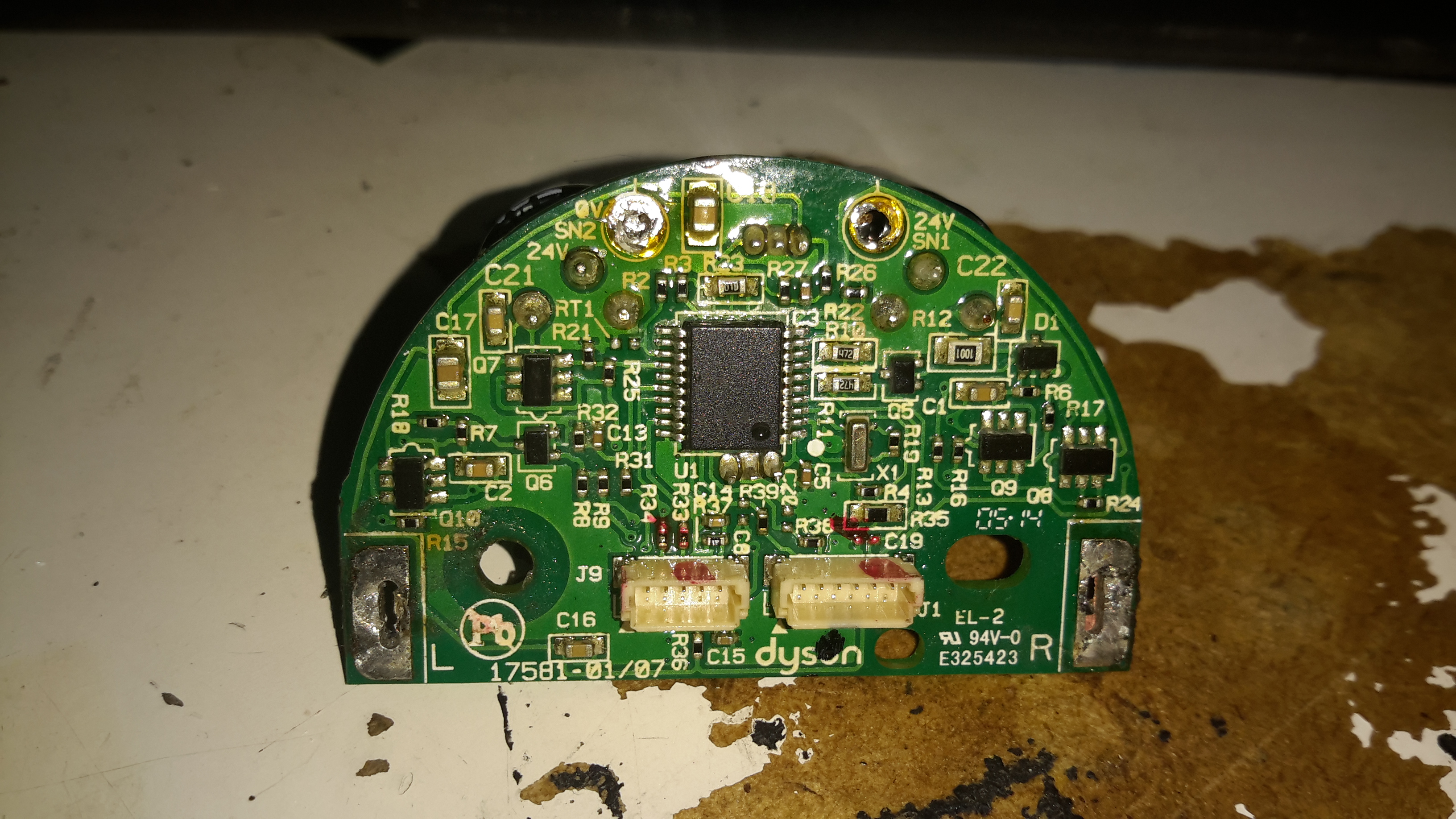
Motor Control Board
The inside face of the control PCB holds the 4 very large MOSFETs, IRFH7932PbF from International Rectifier. These are rated at 30v 20A a piece, and are probably wired in a H-Bridge. There’s a bipolar Hall switch to sense rotor position & rotation speed, and an enormous pair of capacitors on the main power bus.
Motor Control Board Reverse
Not much on the other side of the PCB other than the microcontroller and associated gate drive stuff for the FETs.
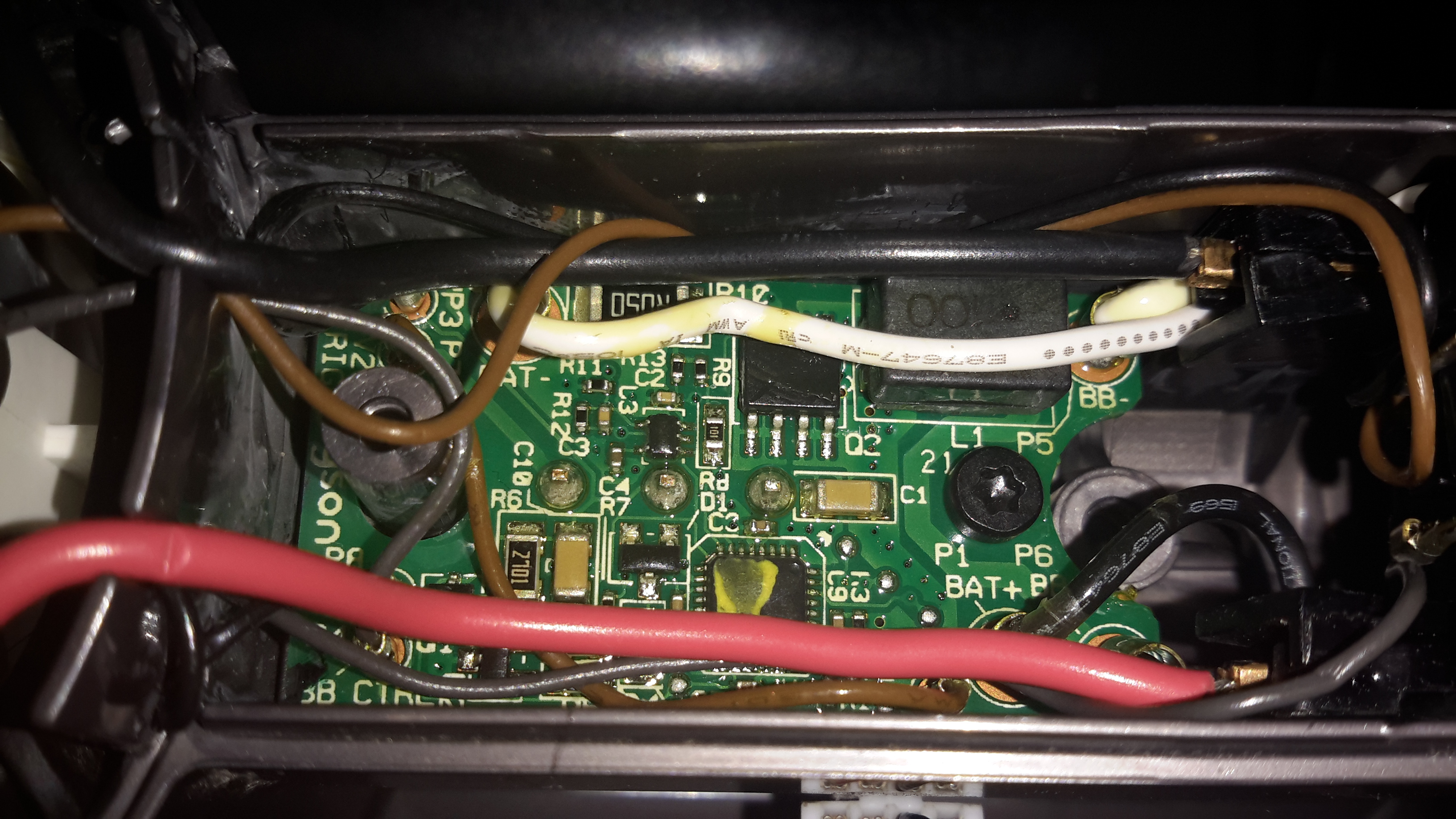
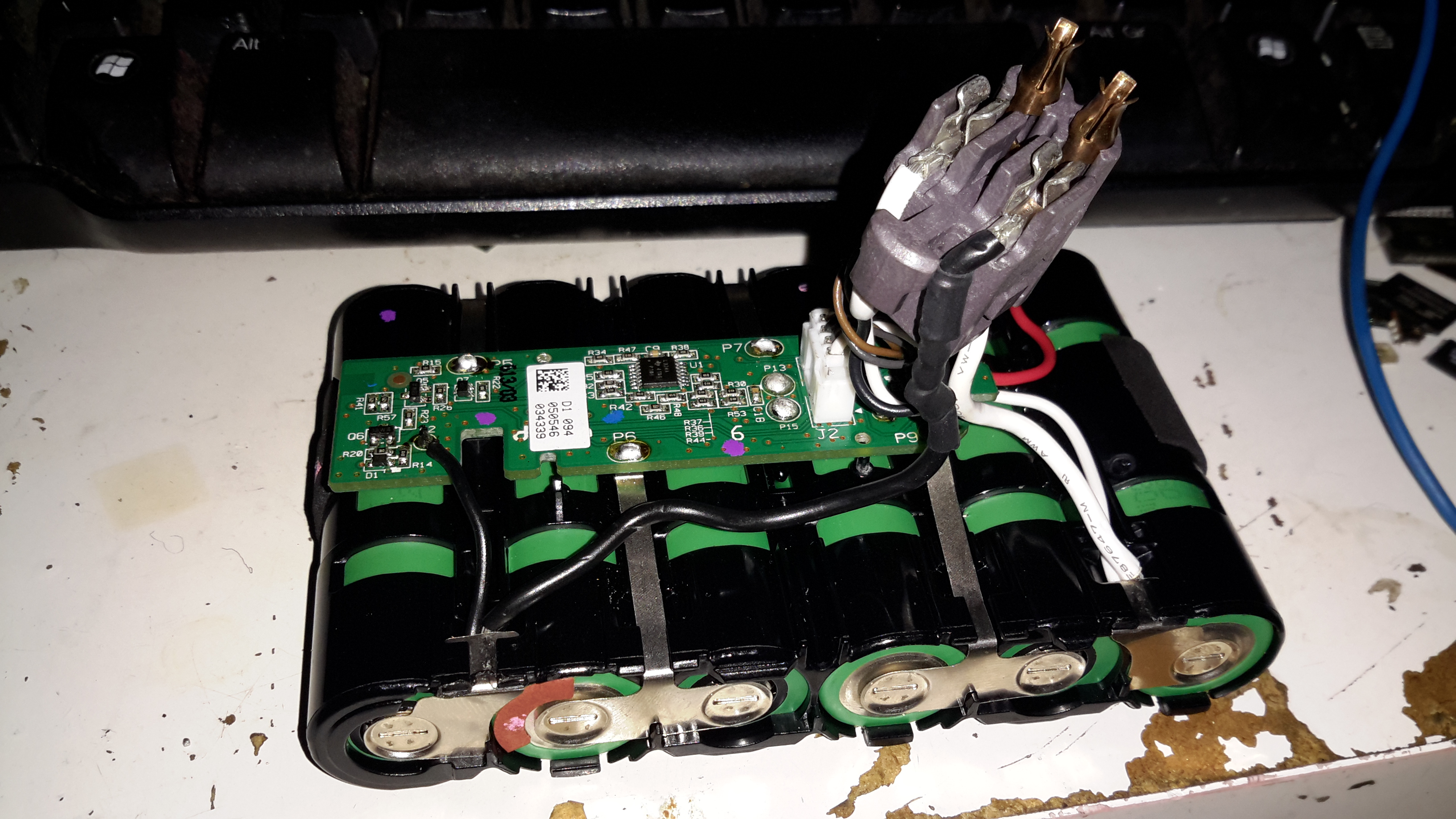
Battery Pack Opened
The battery pack is similar to the DC16 in it’s construction, a heavily clipped together plastic casing holding 6 lithium cells. In this one though there’s a full battery management system. The IC on the top of the board above is a quad Op-Amp, probably for measuring cell voltages.
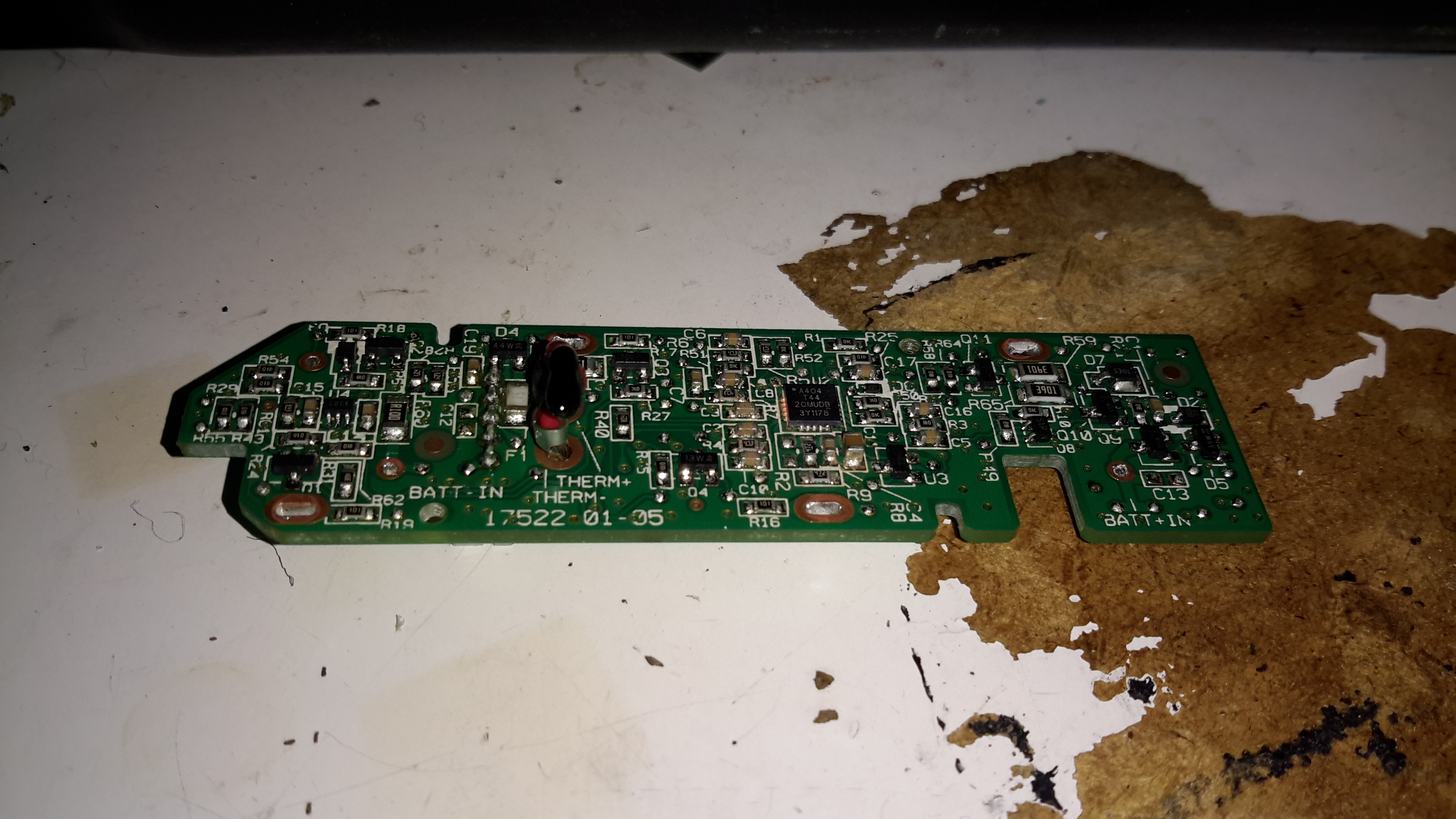
Battery BMS Bottom
The other side of the BMS board is packed with components. I wasn’t able to identify the QFN IC here, as it’s got a custom part number, but it’s most definitely communicating with the main motor MCU via I²C over the two small terminals on the battery connector.
I was looking around eBay for decent deals on a branded CO alarm, and came across these for next to no money, so I thought I’d grab one just to see how bad they could be.
Alarm Opened
Popping the casing open shows the very small circuit board inside, with the CO sensor cell on the right. I can’t find any manufacturer information on this cell, nor can I find a photo of anything similar on the intertubes, so no specifications there. The other parts are pretty standard, a Piezo sounder & it’s associated step-up transformer to increase the loudness.
Sensor Closeup
The sensor cell has the usual opening in the end to allow entry of gas.
Main PCB
The other side of the board doesn’t reveal much, just an LCD, a couple of LEDs, a pair of transistors, Op-Amp for the sensor & a main microcontroller.
MCU
The microcontroller isn’t marked unfortunately. It’s not had the number scrubbed off, it’s just never been laser marked with a part number. Above the micro is a SOT-23 LM321 low-power Op-Amp which does the signal conditioning for the CO sensor.
I tried to make this alarm trigger with the exhaust from the Eberspacher heater, which on a well-made branded alarm registered a reading of 154ppm after a few minutes. In the case of this alarm though, I couldn’t make it trigger at all, no matter how long I exposed it to hydrocarbon exhaust gases. I won’t be trusting this one then!
Nothing quite like a piece of safety equipment that doesn’t work correctly from new!
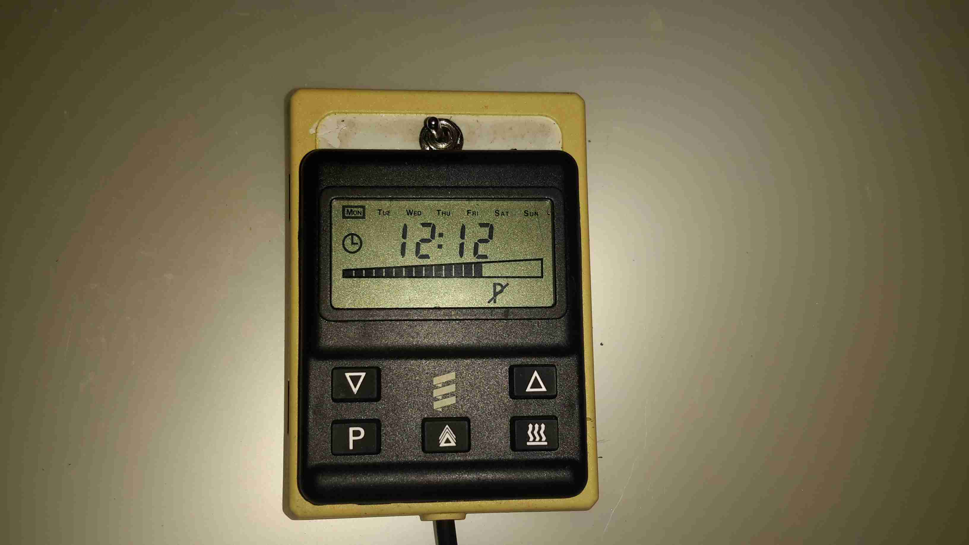
It’s well known that there are two versions of the 701 type controller available for Eberspacher heaters, the version with the blue logo is the official un-restricted model, while the version with the white logo is a version built for BT that restricts the heater to 1 hour runtime & has no diagnostics built in.
As these devices are microcontroller driven, I assumed that the hardware would be the same, only the code running in the micro being the bit that Eberspacher changed. This option would certainly have been the lowest cost.
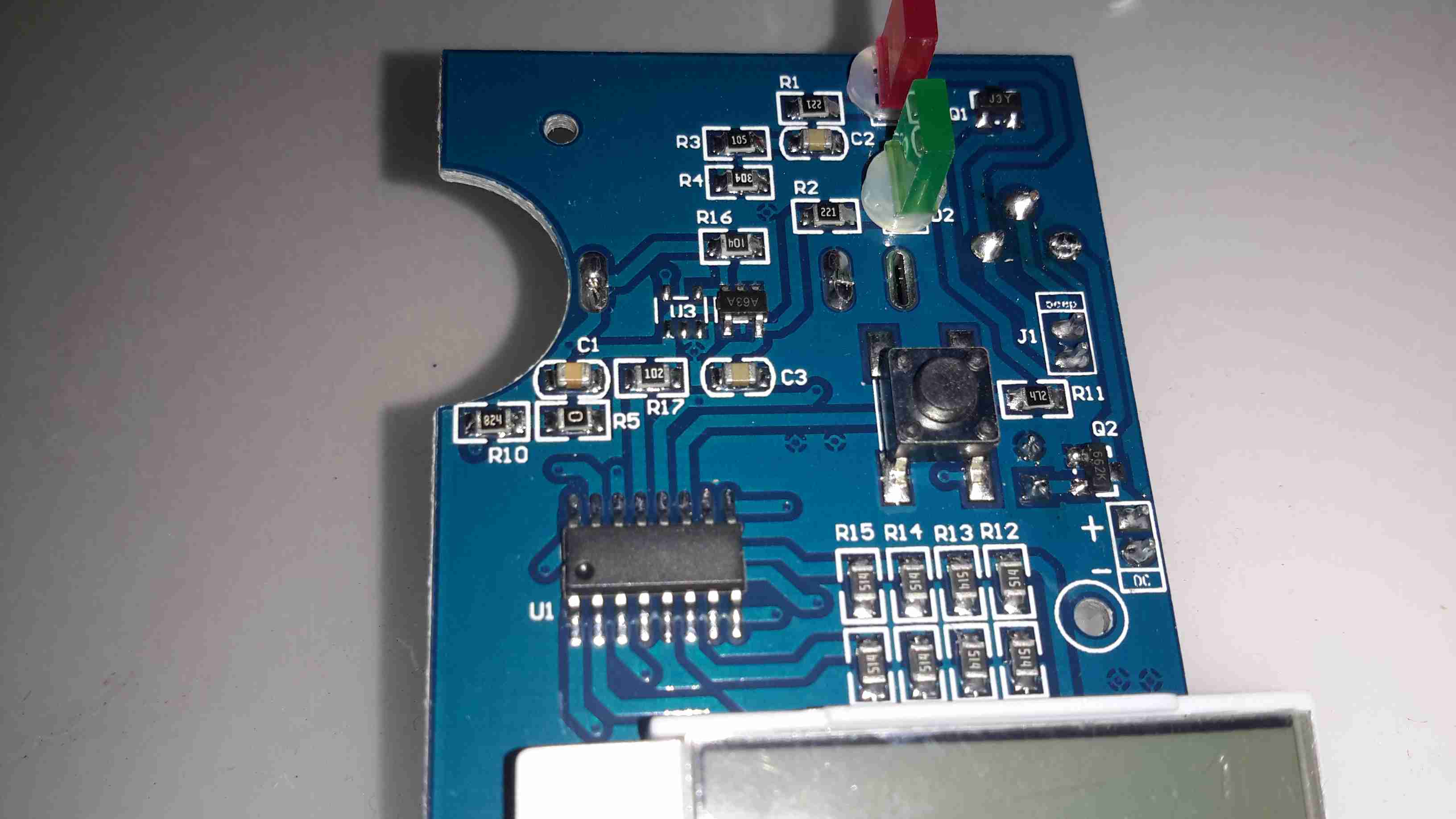
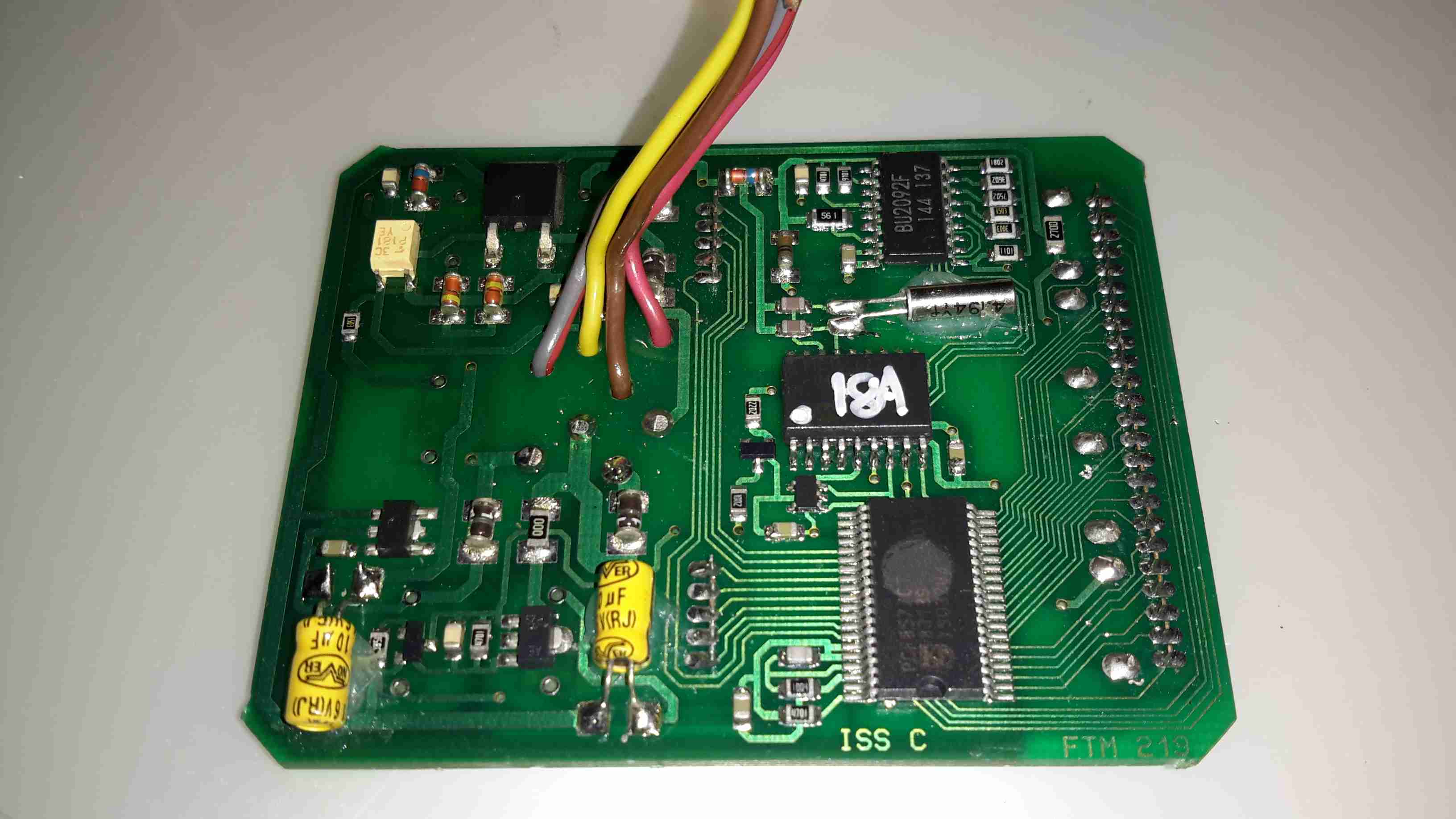
Controller PCB Rear
Here’s the PCB removed from the plastic housing. There are definitely some differences that I can tell. As the un-restricted version has an extra wire for the diagnostic serial interface, and this board has no unpopulated parts, the PCB is definitely a different version.
In the centre is a Microchip PIC16C622 microcontroller, the OTP version in this case for cost reductions. (I may try reading the binary from this chip in the future, chances are it’s code protected though).
Below the micro is an NXP PCF8577C 32-segment LCD controller, this has an I²C interface to the PIC.
The temperature control function on these heaters is done via applying a resistance to one of the control lines, between 1750Ω-2180Ω, ±80Ω. (Very odd values these, not to mention no standard components can create this range easily, bloody engineers >_<). This is accomplished in hardware with a BU2092F I²C shift register from Rohm, which is connected to a bank of resistors. The microcontroller will switch combinations of these into the circuit to get the range of resistances required.
The rest of the circuit is local power regulation & filtering.
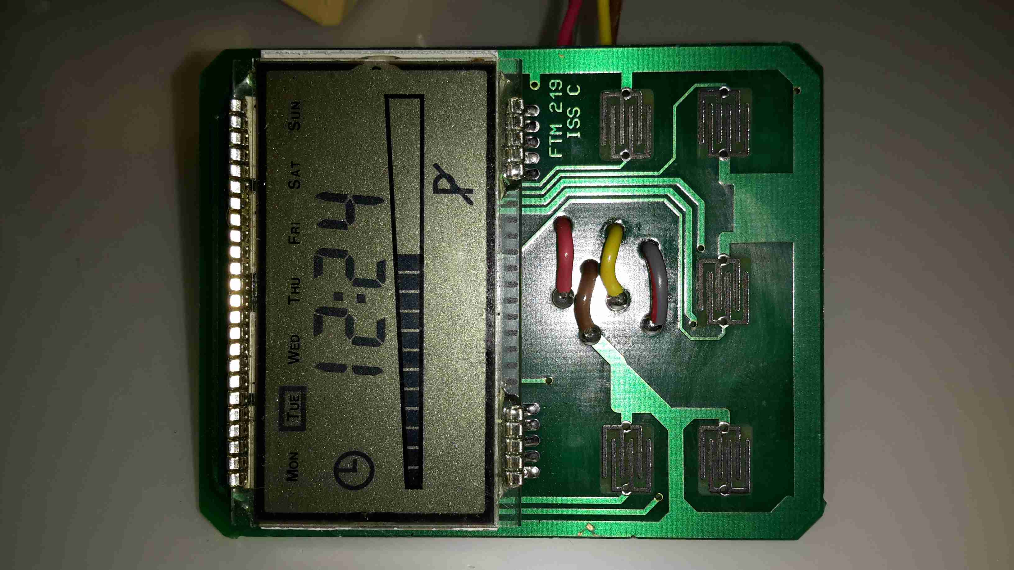
Controller PCB Front
There’s not much on the other side of the PCB, just the LCD itself & the contacts for the buttons.
The Eberspacher heaters can be controlled with a single switch, but it’s more convenient to have some temperature control & the option of a timer. Above is an ex-BT 701 series controller, with built in 7-day programmer. Being an ex-BT van version though, it’ll only switch the heater on for 1 hour at a time.
To get around this slight niggle, I fitted a bypass toggle switch.
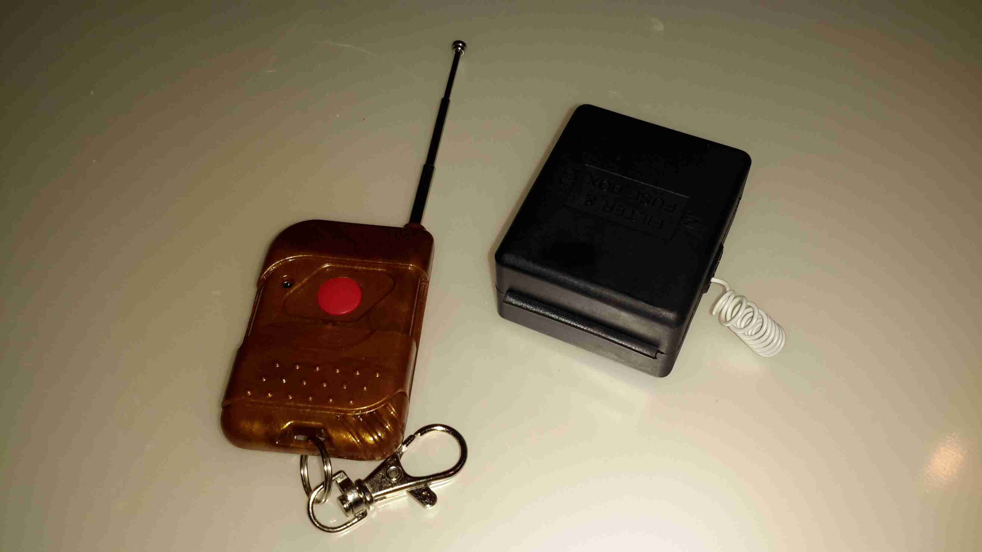
Remote Control
For a bit of extra convenience, I got an RF remote controlled relay module from eBay (£5).
This allows me to switch things on remotely, so I can return to a nice toasty tent while camping.
There is an official RF remote for Eberspacher heaters, but I’ve no doubt they’re hideously expensive.
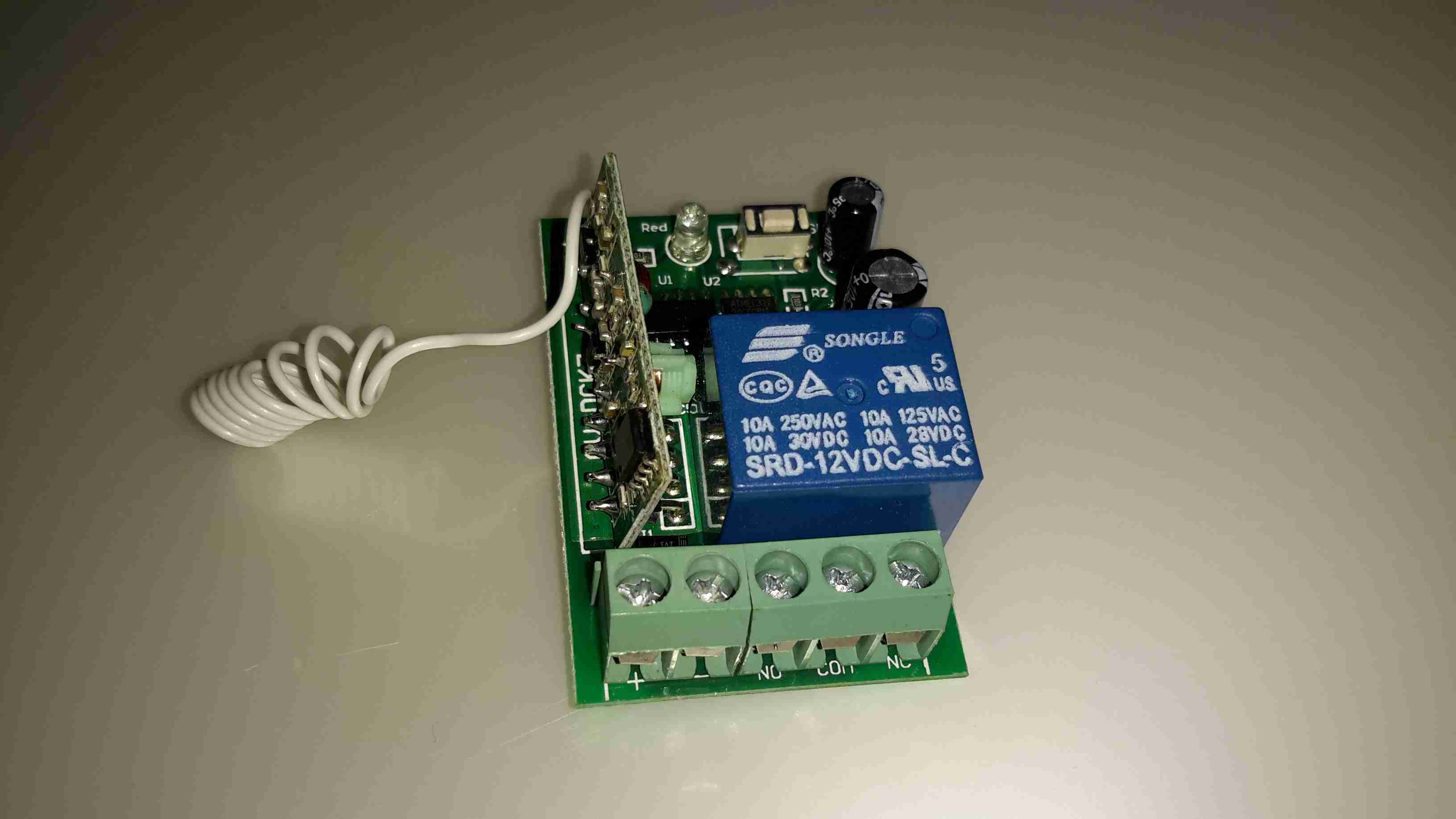
RF Receiver
Here’s the receiver PCB, there’s an EEPROM & a microcontroller onboard for handling the codes the remotes send, but as the number has been scrubbed off the micro, no data there. This uses a standard RF receiver module.
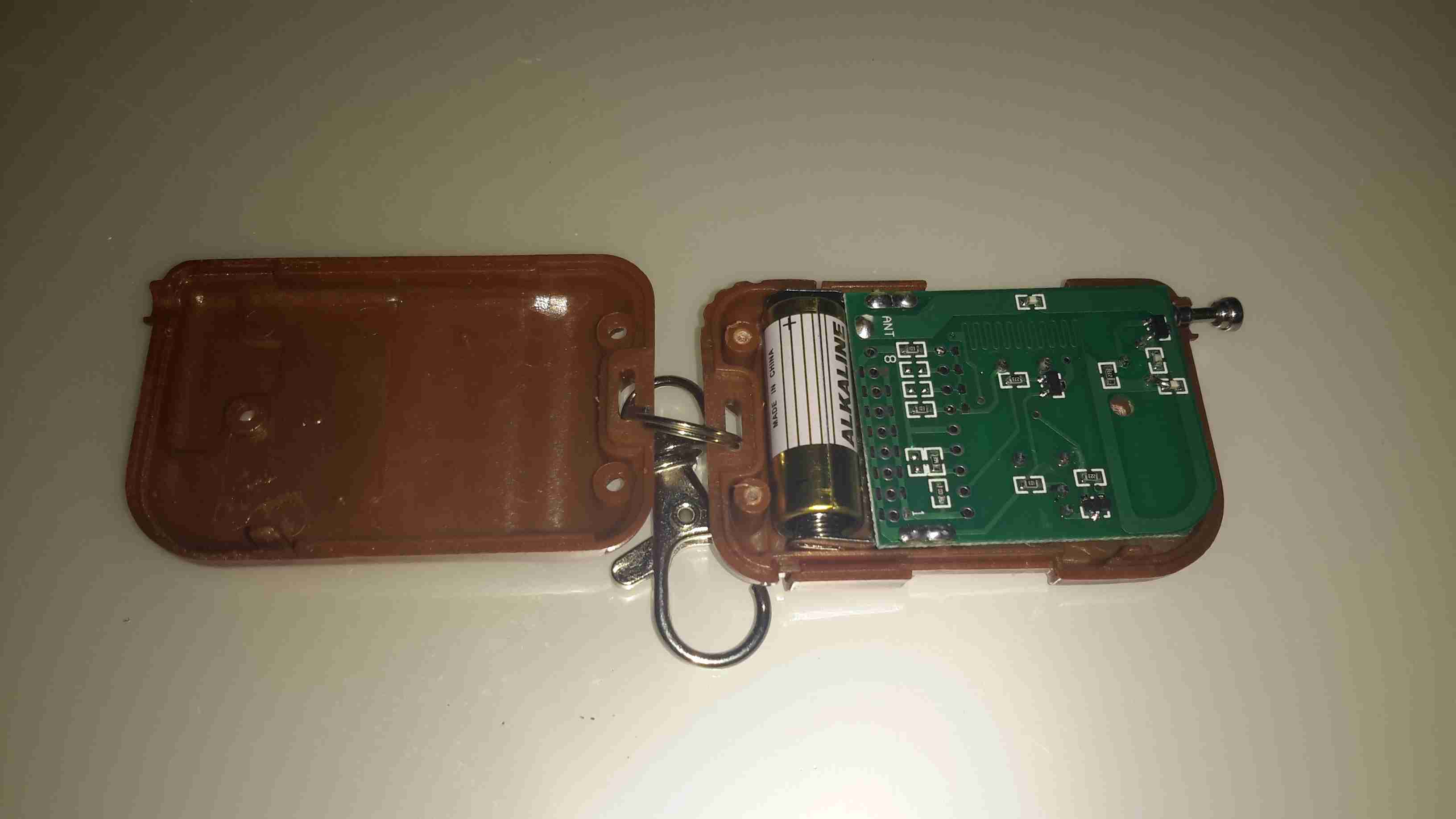
RF Remote
Here’s the remote itself, this uses a 12v battery instead of a 3v lithium cell. A little of a pain since these batteries can be a bit pricey.
As this RF system operates on 315MHz, it’s technically illegal in the UK, but I was unable to find a 433MHz version with the features required. Nevermind ;).
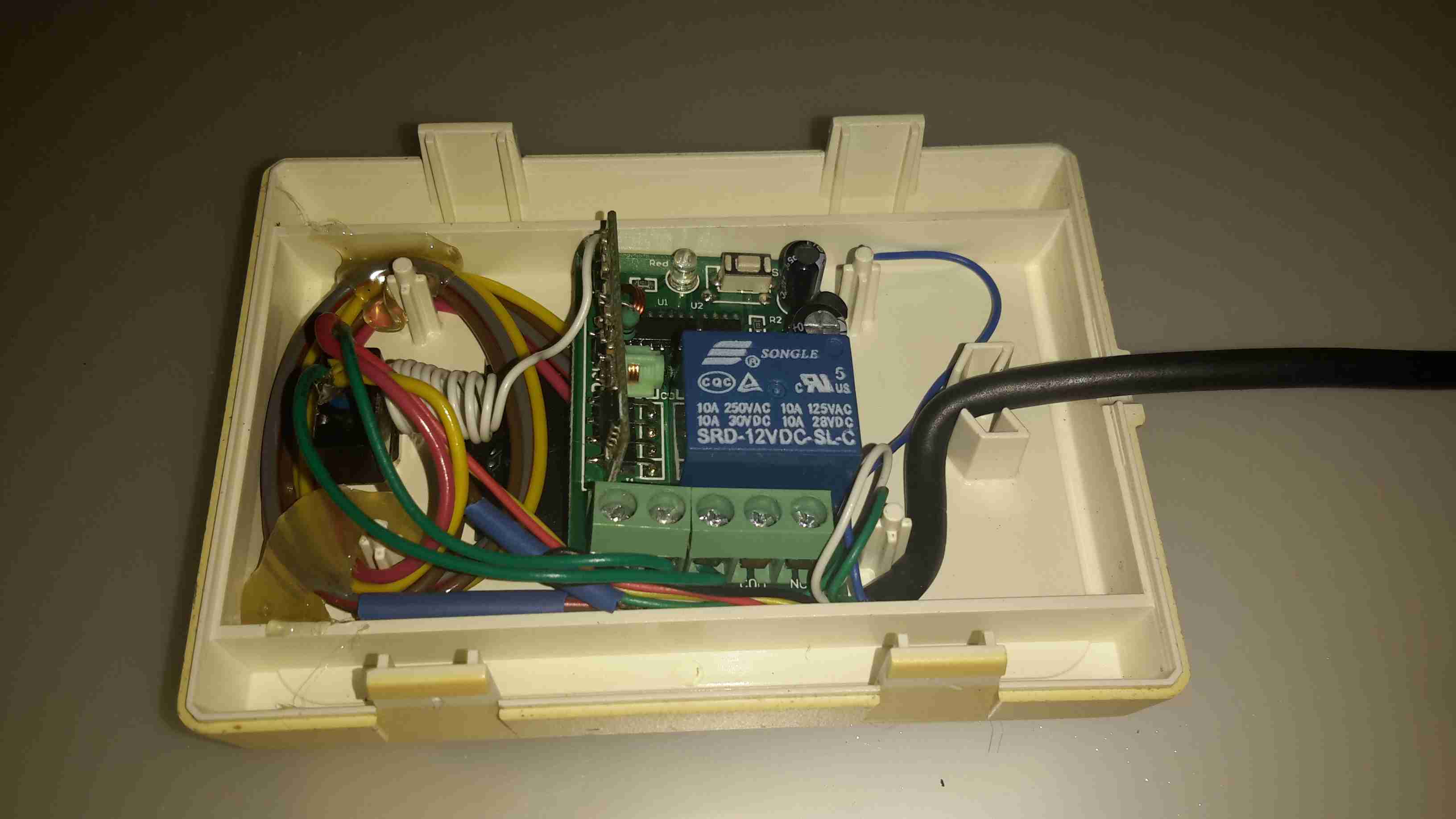
Controller Internals
Here’s the module installed in the controller casing. I have since run the antenna wire around the edge of the case to try & get the furthest range on receive. The relay contacts are just paralleled across the bypass switch, so when the relay energizes the heater fires up.
Luckily the thermostatic control portion of the 701 programmer is operational even when heating mode is not active.
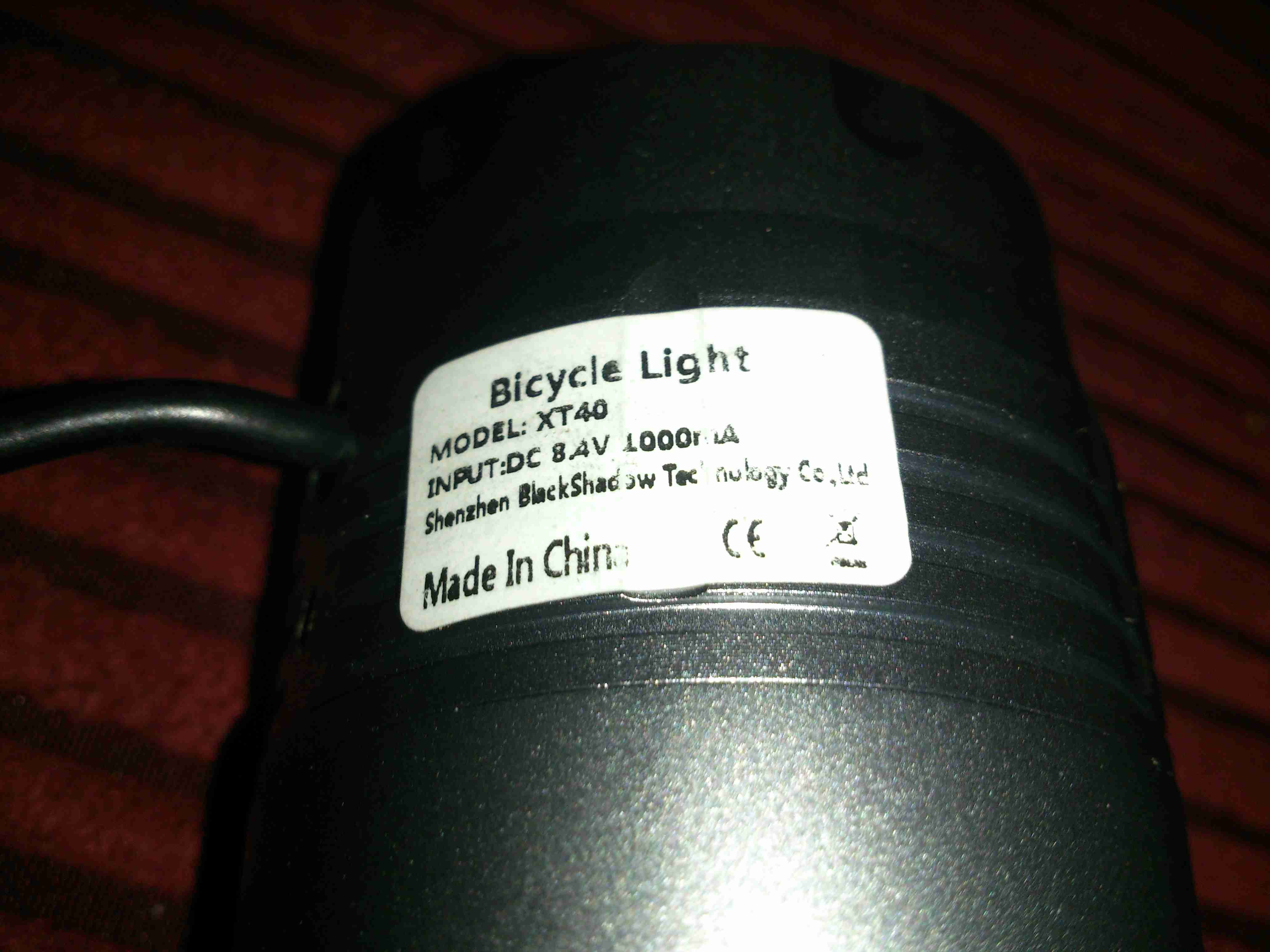
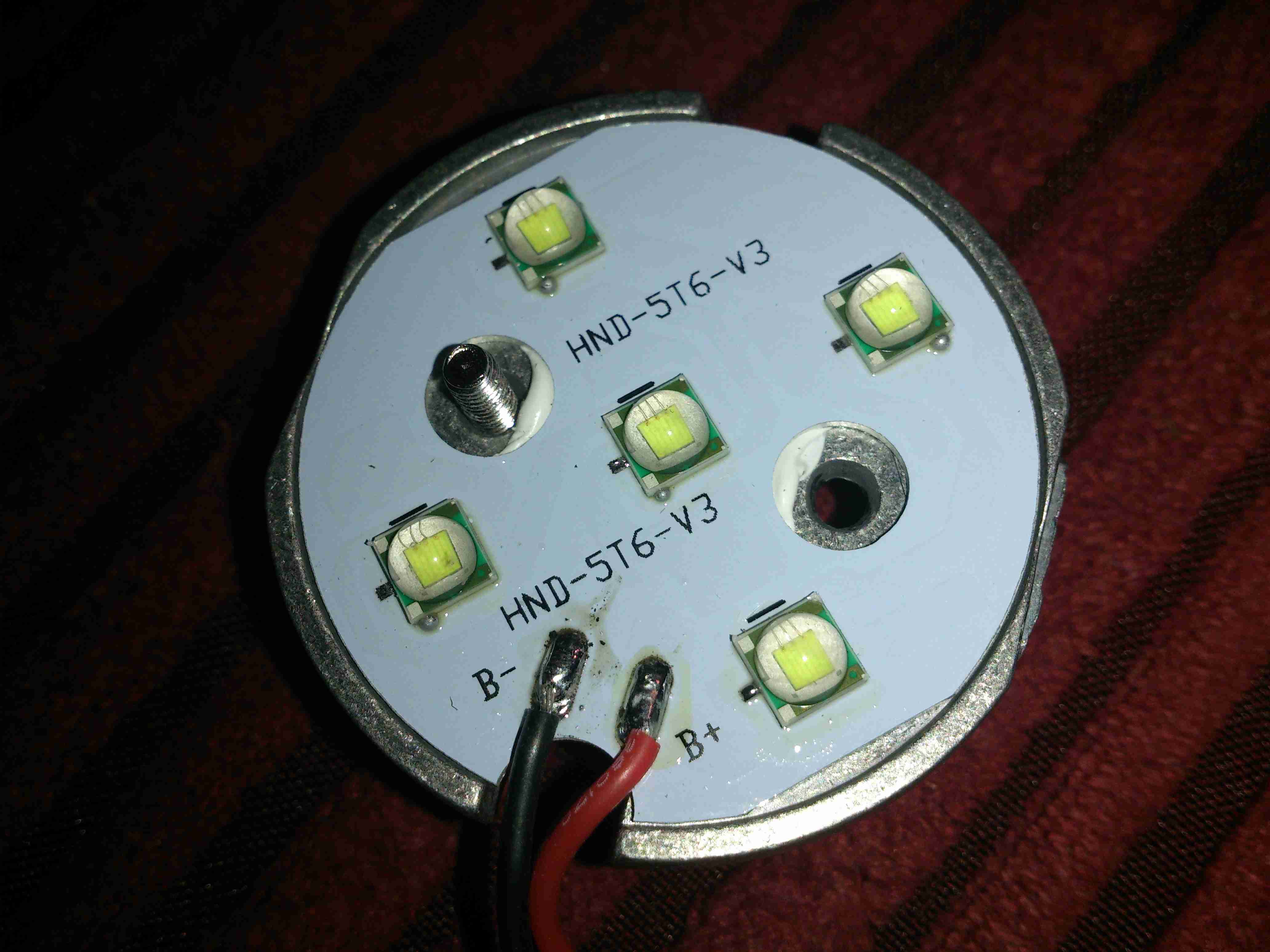
Here’s another torch from eBay, this time with 5 Cree XML-T6 LEDs.
Label
Having 5 Cree LEDs rated at up to 3A a piece, this light has the capacity to draw about 50W from it’s power supply. In this case though, current draw is about 1.5A at 12v input on the full brightness setting.
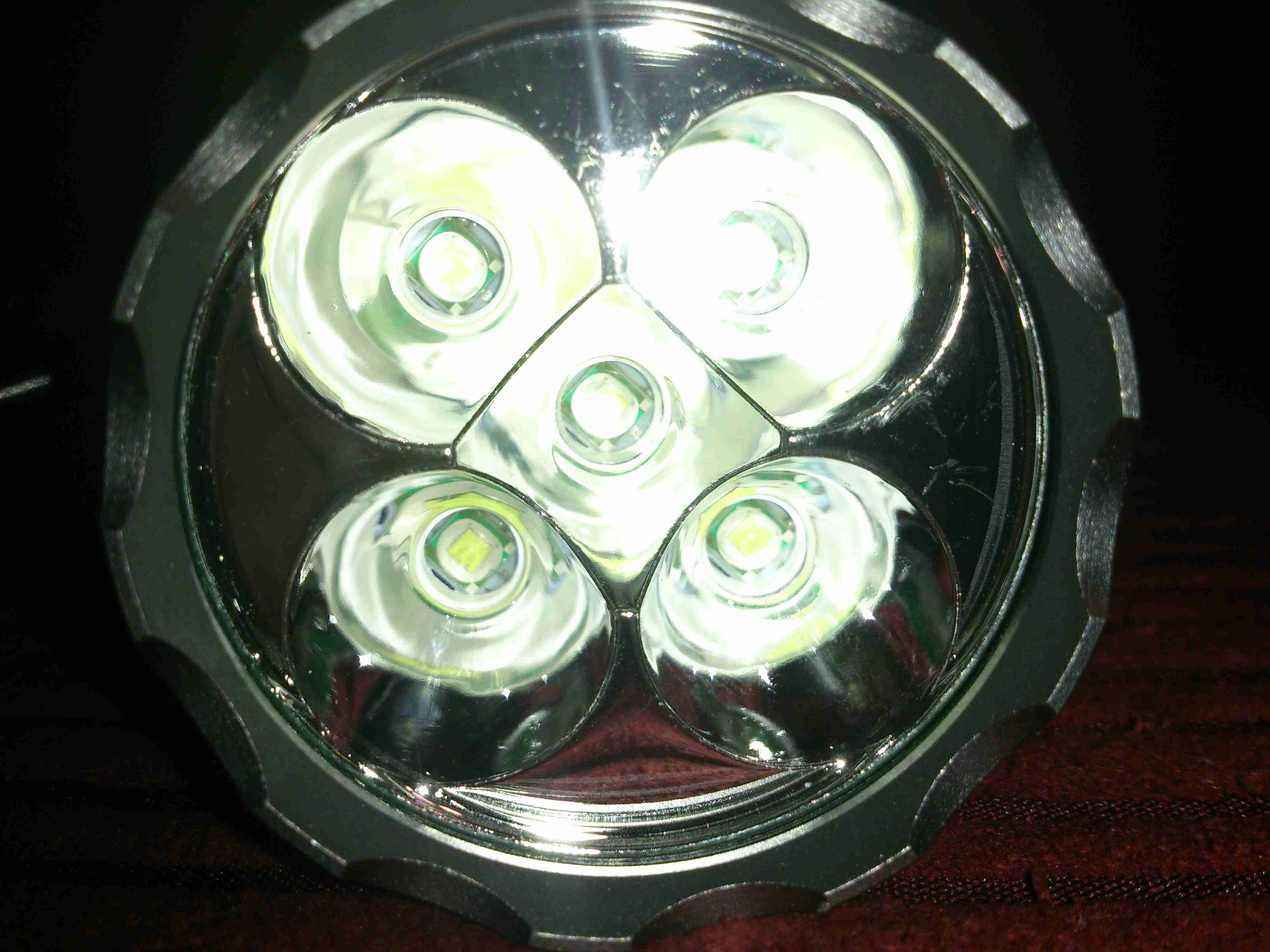
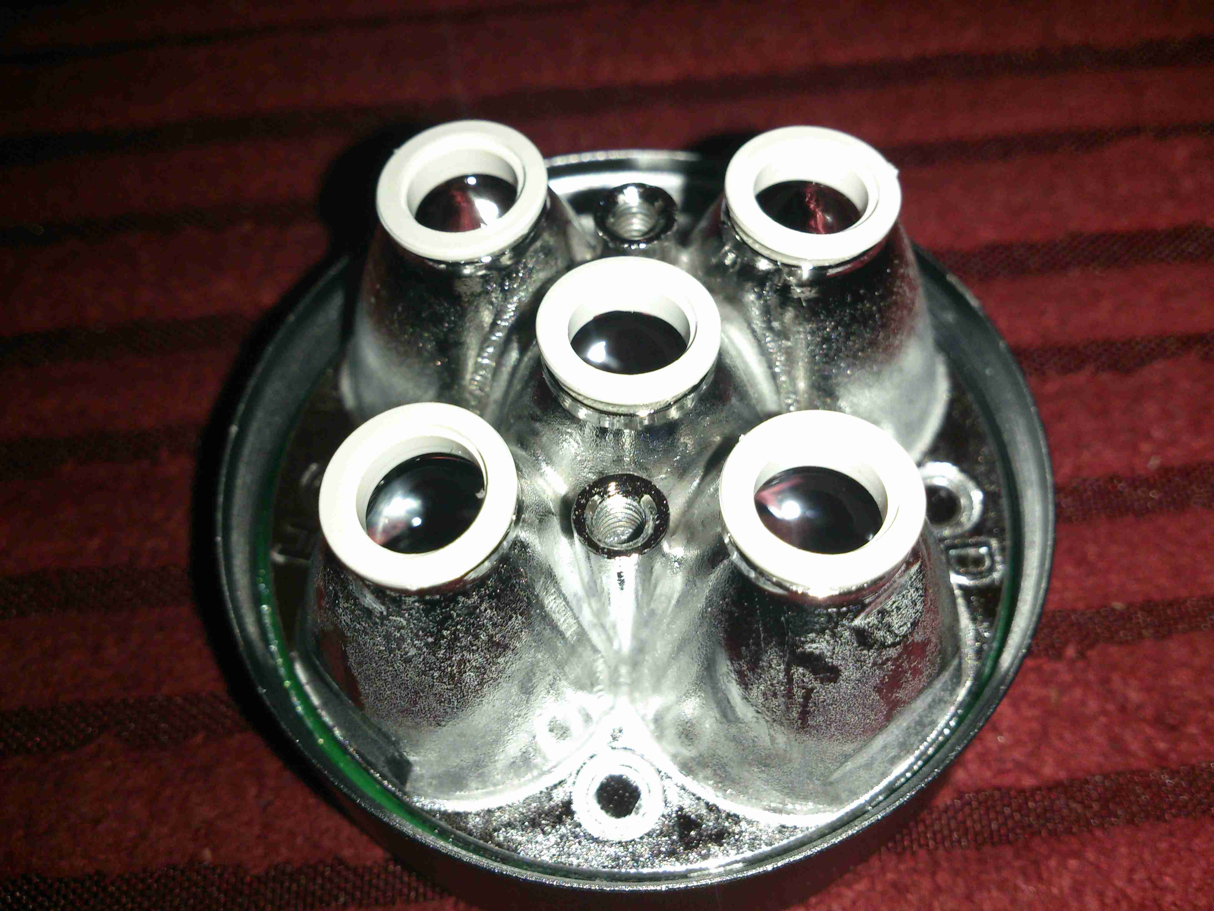
Cree LED Torch
Here’s the LEDs mounted into the reflector. Fitting this many high power LEDs into a small space requires some serious heatsinking. The casing is made of machined aluminium.
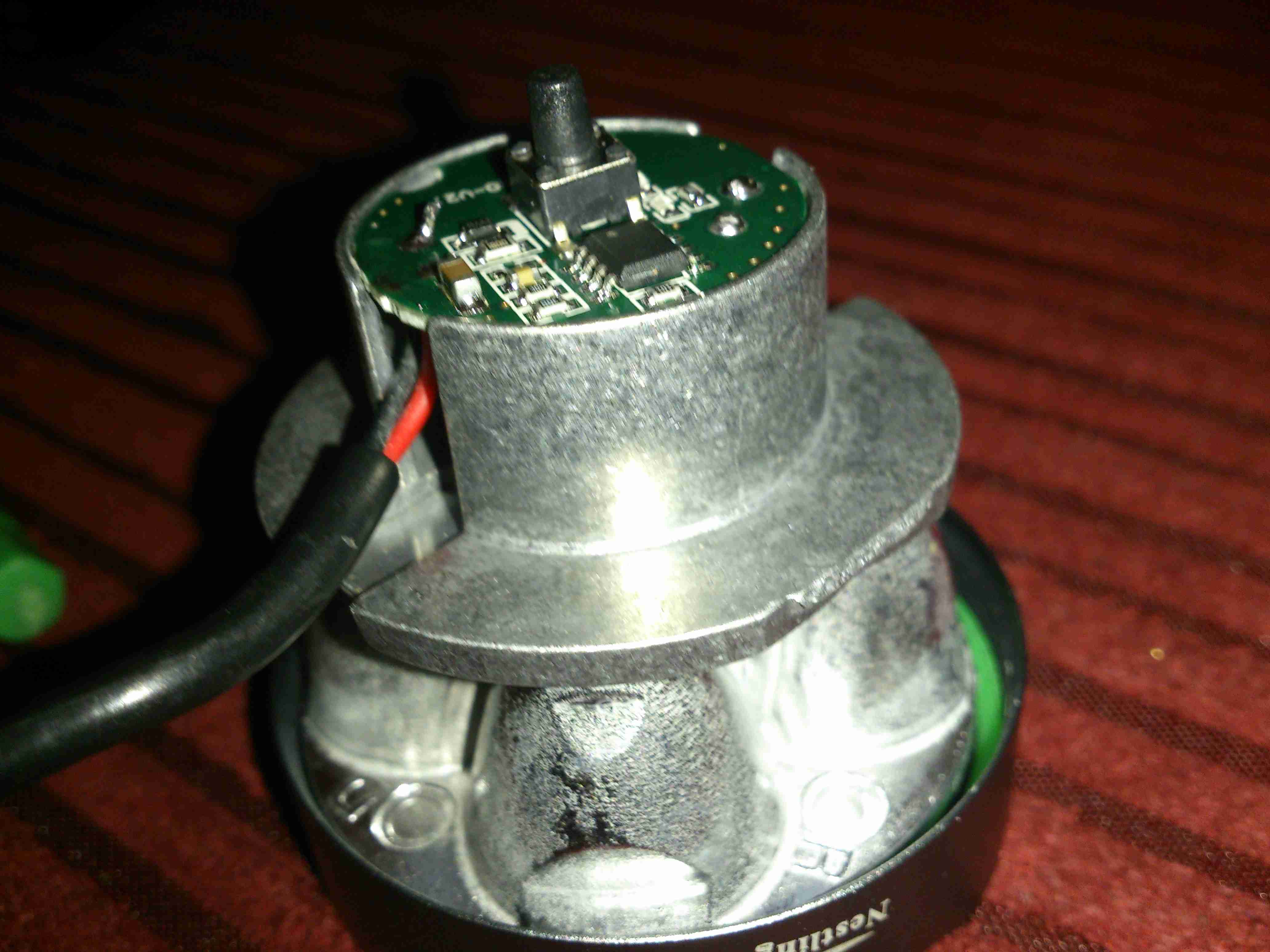
LED Module
Unscrewing the front bezel allows the internals to come out. The core frame & reflector is all cast alloy as well, for heatsinking the LEDs. The controller PCB is mounted into a recess in the back of the LED mount.
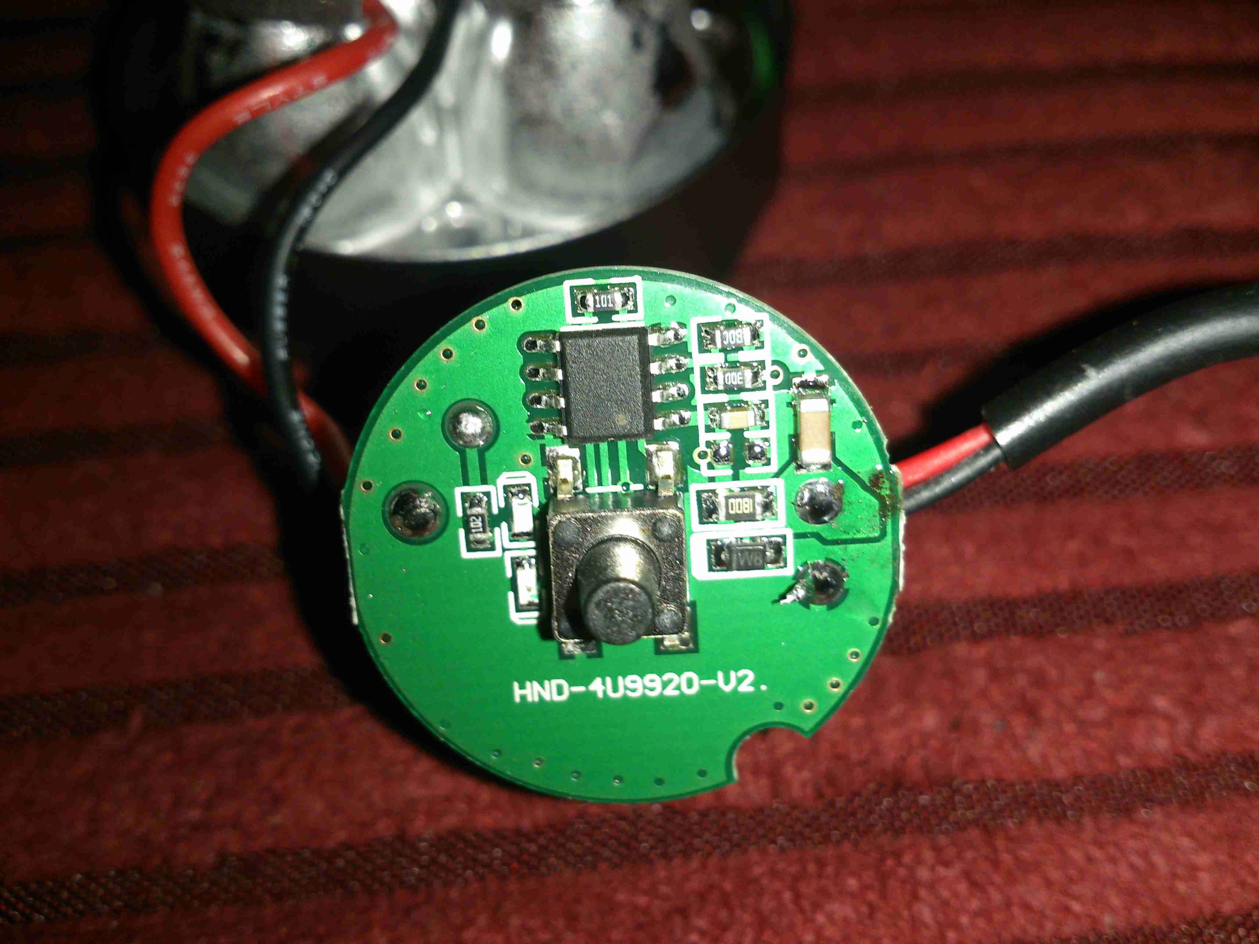
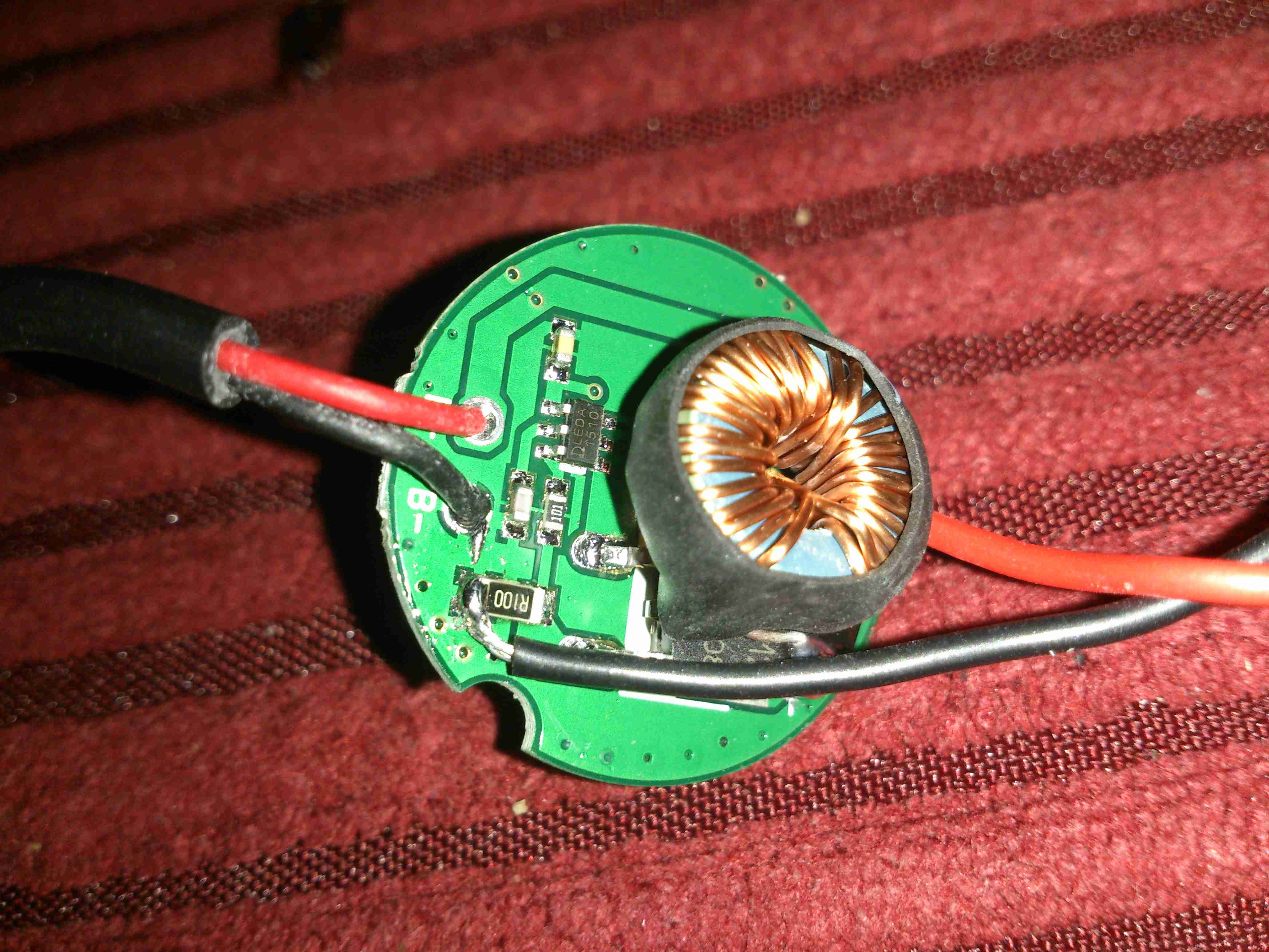
Controller
Here’s the controller itself. The usual small microcontroller is present, for the multiple modes, and handling the momentary power switch.
Switching Inductor
As all the LEDs on this torch are connected in series, their forward voltage is ~12-15v. The battery is an 8.4v Li-Ion pack, so some boost conversion is required. This is handled by the circuitry on the other side of the board, with this large power inductor.
Reflector
The reflector screws onto the front of the LED array, centered in place with some plastic grommets around the LEDs themselves.
LED Array
Finally for the torch, the LED array itself. This is attached to the frame with some thermal adhesive, and the LEDs themselves are mounted on an aluminium-core PCB for better heat transfer.
This module unsurprisingly generates quite some heat, so I have improved the thermal transfer to the outer case with some thermal grease around the outer edge.
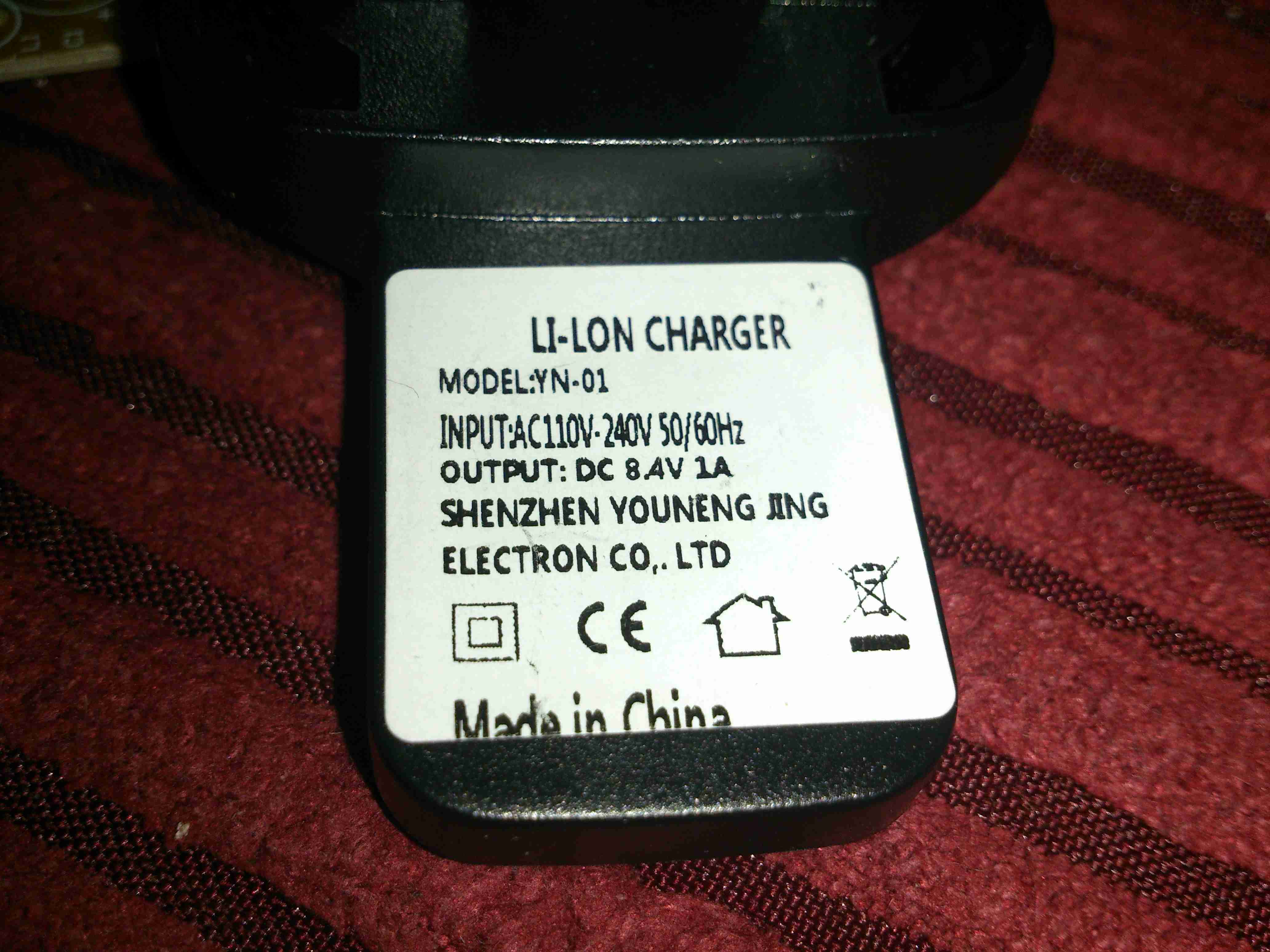
Charger
The supplied charger is the usual Chinese cheapy affair, claiming an output current of 1A at 8.4v. I never use these chargers, so they get butchered instead.
Charger PCB
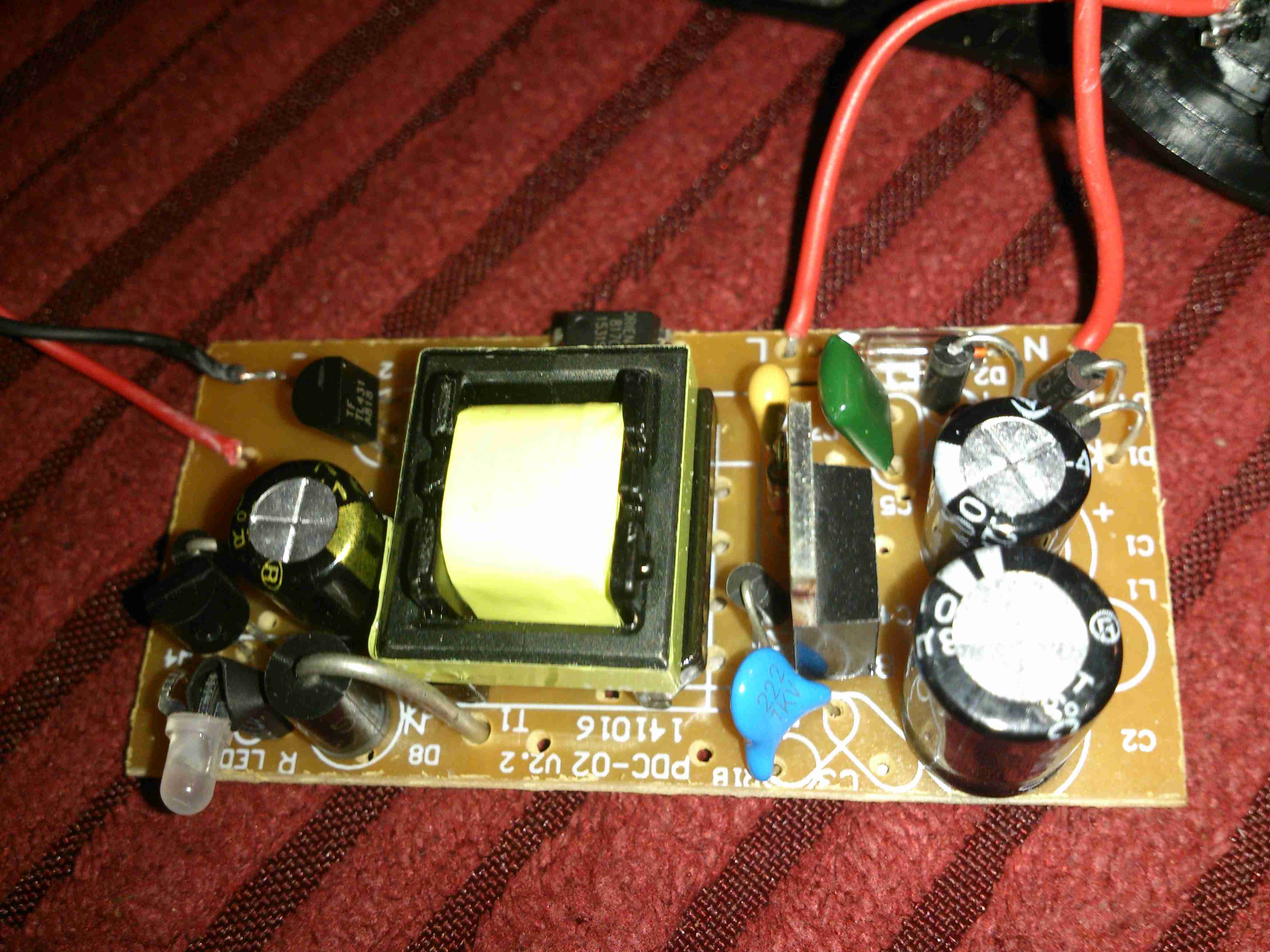
Here’s the main PCB. Overall the construction isn’t that bad, the input mains is full-wave rectified, but there is little in the way of RFI filtering. The supply is fused, but with an absolutely tiny glass affair that I seriously doubt has the ability to clear a large fault current.
Like many cheap supplies, the output wiring is very thin, it’s capacity to carry 1A is questionable.
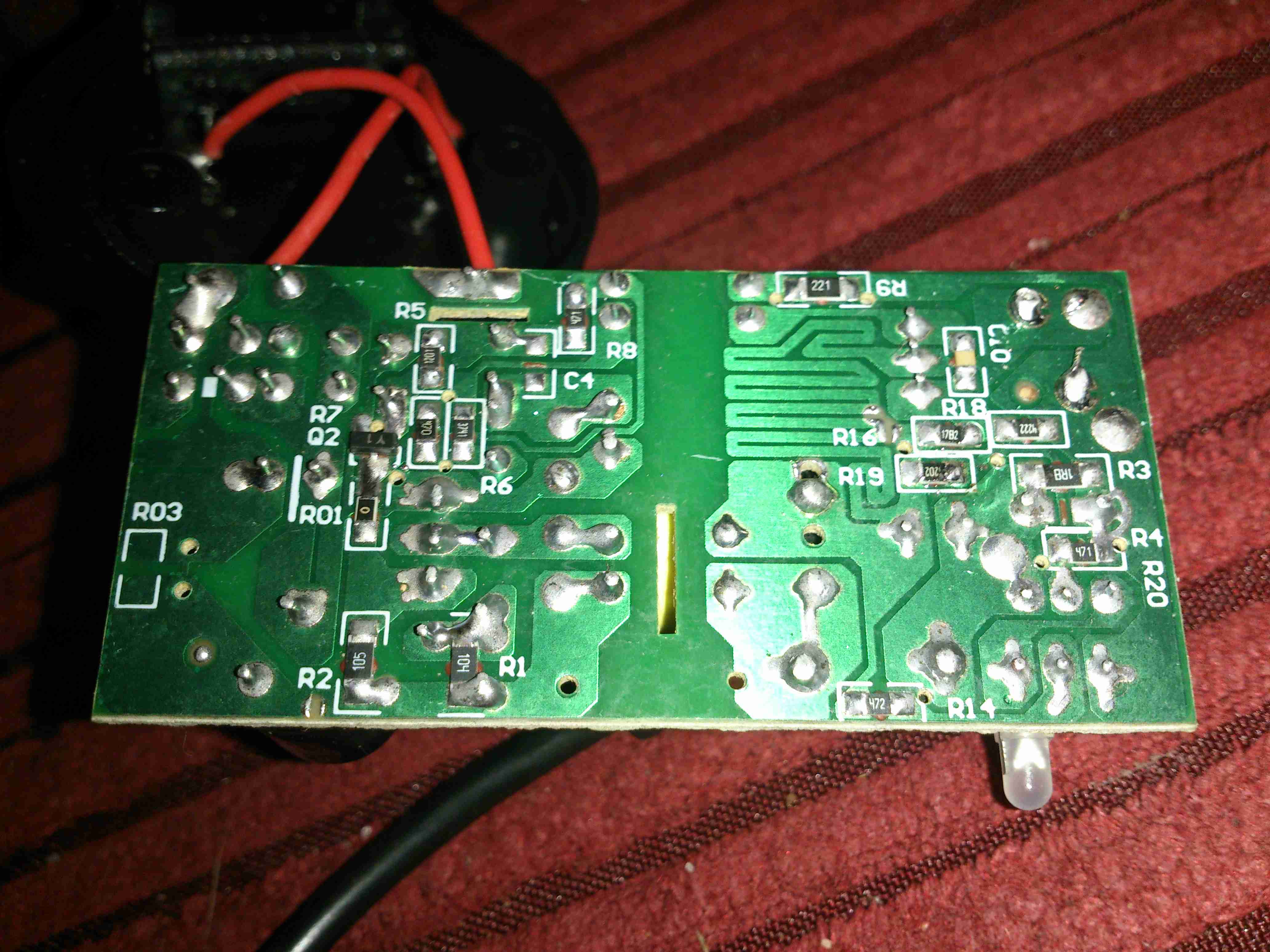
PCB Reverse
On the reverse side, there’s a nice large gap between the mains side & the low voltage output. There’s even an anti-tracking slot under the optoisolator.
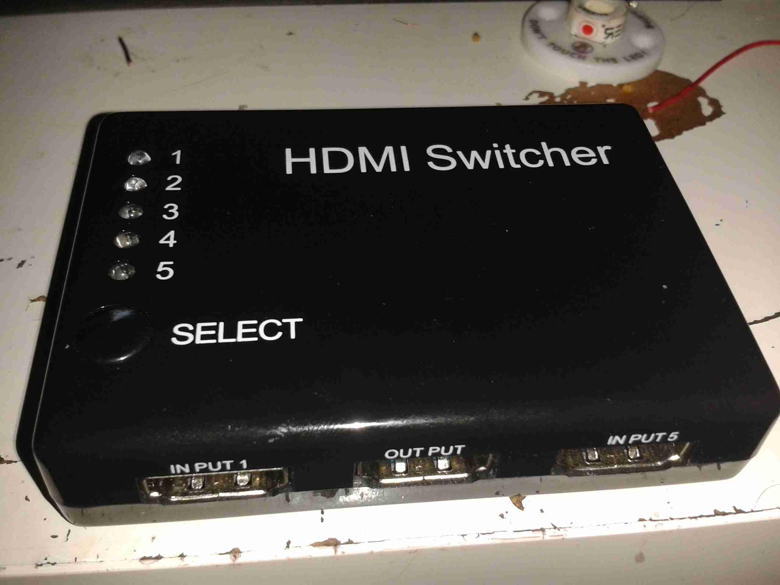
Here’s another quick teardown, a cheap 5-port HDMI switch box. This is used to allow a single input on a monitor to be used by 5 different external HDMI devices, without having to mess about plugging things in.
Power & Remote
Here’s the DC barrel jack & 3.5mm TRS jack for power & remote control. There’s a little IR decoder & remote that go with this for hands free switching.
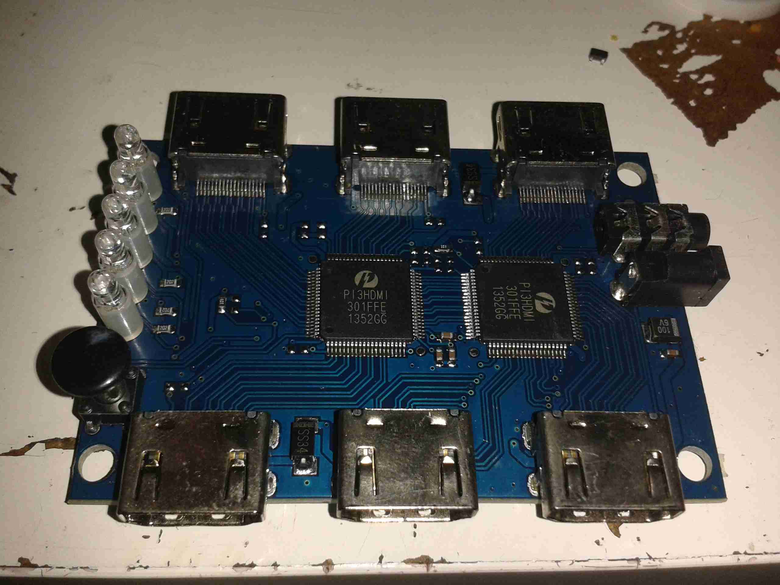
PCB Top
Here’s the PCB out of it’s plastic housing. The main logic is a pair of PI3HDMI303 3:1 HDMI switches from Pericom Semiconductor. These are cascaded for the 5-ports, the first 3 input HDMI ports are switched through both ICs to reach the output.
These HDMI switch ICs are operated with TTL input pins, the combination of these pins held either high or low determines the input port that appears on the output.
There’s a button on the left for switching between inputs, with a row of 5 LED indicators.
PCB Bottom
Not much on the bottom side, a lot of passives & bypass capacitors. There’s a 3.3v LDO regulator on the left for supplying the main rail to the active switch ICs. The IC on the right doesn’t have any numbering at all, but I’m presuming it’s a microcontroller, dealing with the IR remote input & pushbutton inputs to switch the inputs.
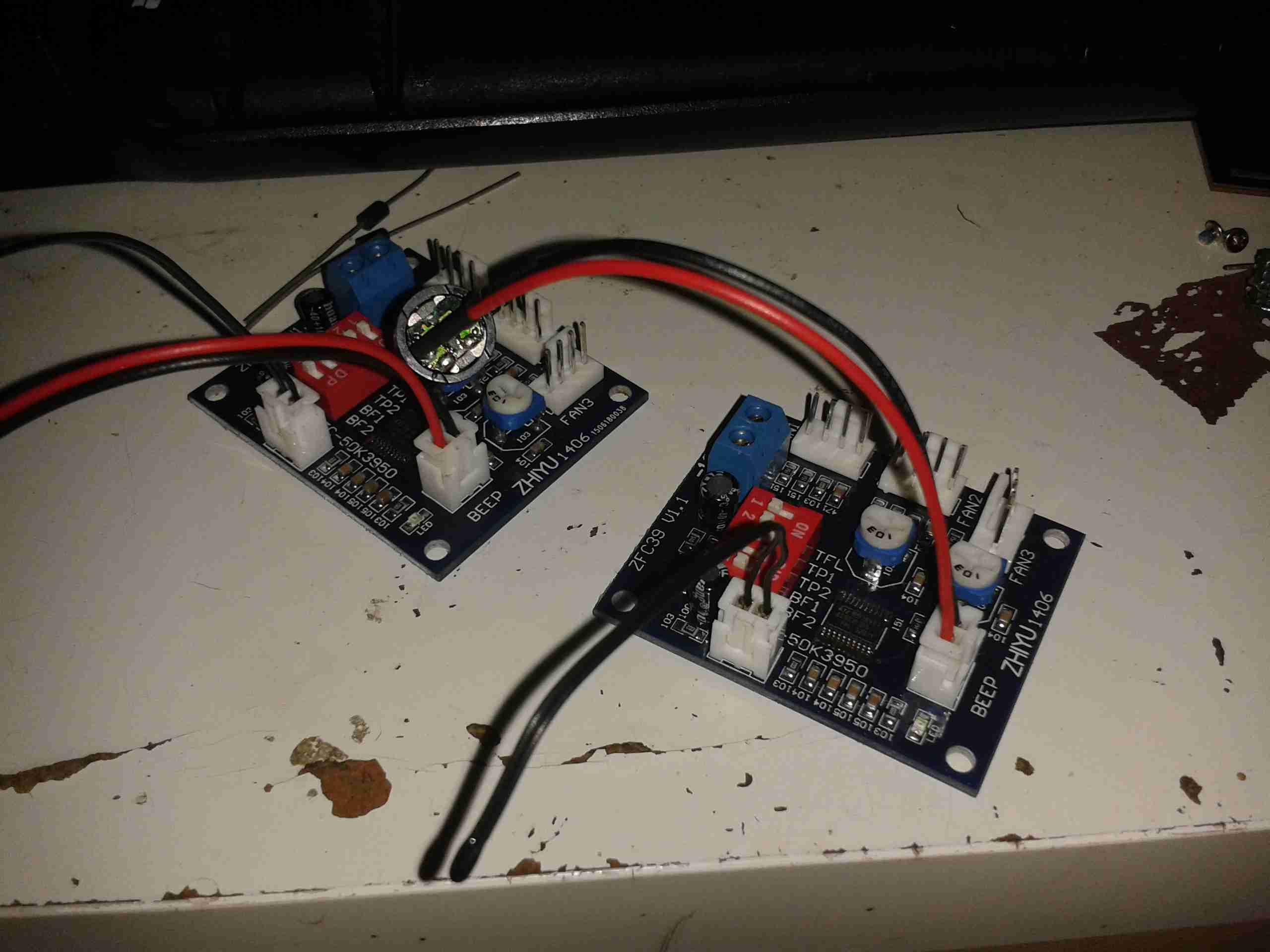
Finally, after a couple of weeks wait time, the fan controllers for the power supplies have arrived. They’re small boards, which is good for the small space left inside the case of the supply.
Controller Boards
Here they are. I’m not certain what the pair of potentiometers are for – there’s no mention of them in the documentation. Possibly for calibration.
Beepers are supplied so an alarm can be heard if the fan fails – very useful for this application.
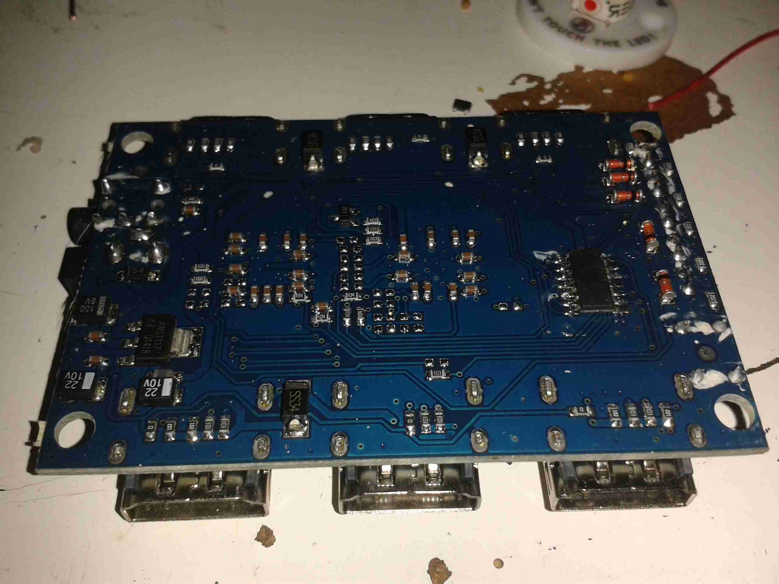
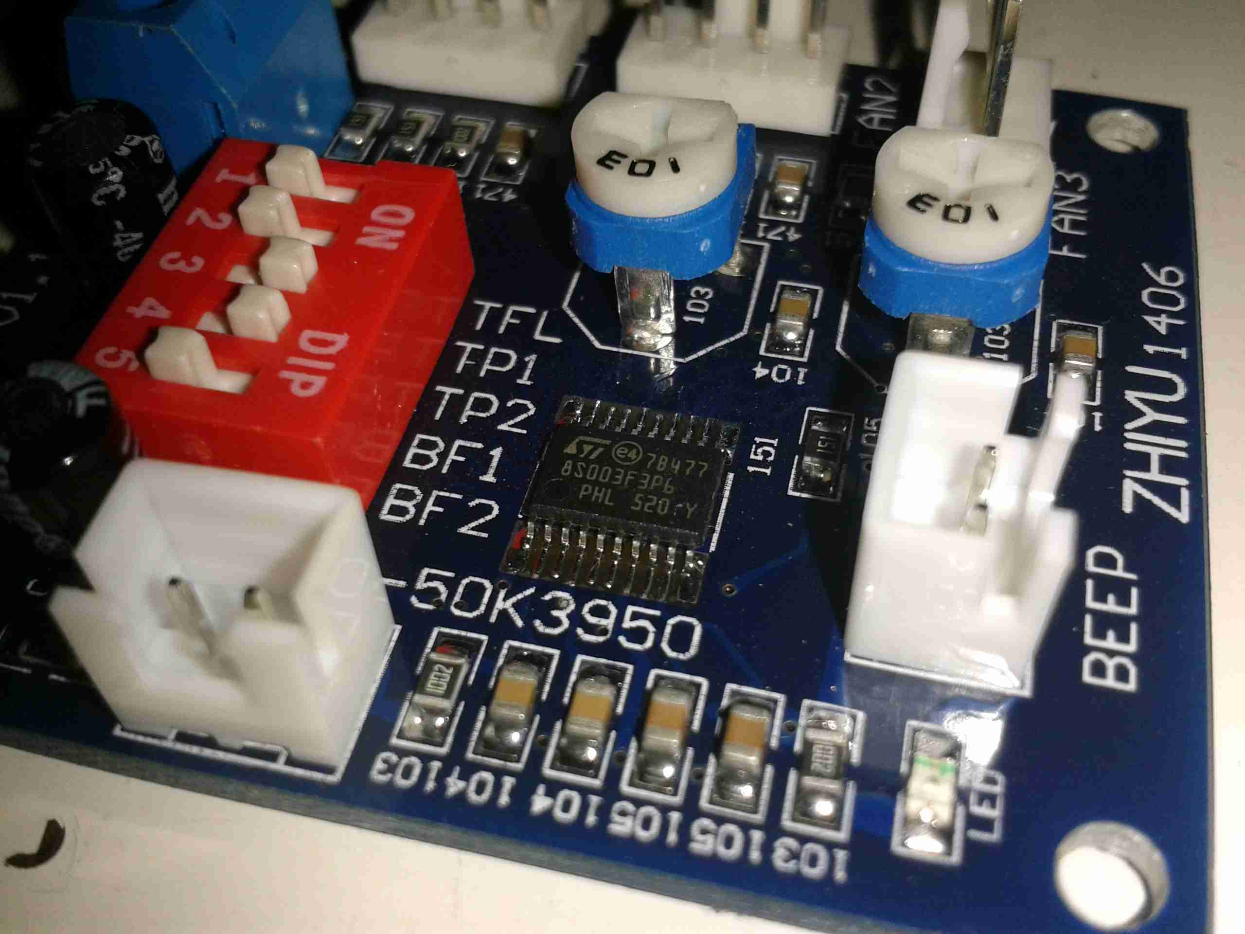
Controller Closeup
Here’s a closeup of the PCB. Options are set with the DIP switch bank on the left, details for that below. The main IC is a STM8S103F3 flash microcontroller.
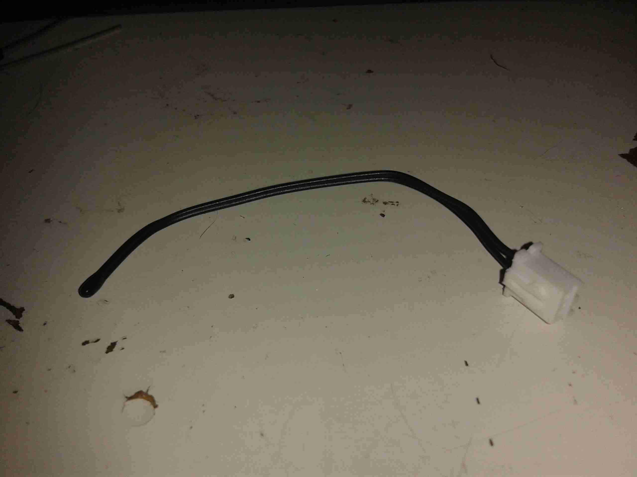
Temperature Probe
The only issue at the moment is that the temperature probe leads are much too short. I’ll have to make a small modification to get enough length here.
Here’s all the details on the boards, more for future reference when they undoubtedly vanish from eBay 😉
Specifications
Working voltage:DC12V
Circuit load capacity: maximum current per output 5A, the bus currents up 9A
Output Range: The first channel 20% -100%, or 40% -100% (TFL = ON)
The second channel and the third channel 10% -100%
(Note: Above range only for PWM range, the actual control effect will vary depending on the fan.)
Temperature probe parameters: 50K B = 3950
Thermostat temperature zone error: error depending on the temperature probe, generally 3-5%
Stall alarm minimum speed: 700-800 rpm
Function setting switch Description:
TFL (No. 1): The lowest temperature channel PWM setting, when ON state FAN1 PWM minimum is 40%, when OFF the minimum PWM of FAN1 is 20%.
TP1 TP2 (No. 2,3): Temperature channel control temperature zones are interpreted as follows (need to used with the temperature probe):
TP1
TP2
Accelerating temperature
Full speed temperature
OFF
OFF
35℃
45℃
ON
OFF
40℃
55℃
OFF
ON
50℃
70℃
ON
ON
60℃
90℃
When the temperature lower than the accelerated temperature, then output at the minimum rotation speed; when it exceed over the full temperature, then always output at full speed.
BF1 BF2 (No. 4,5): corresponds FAN1 FAN2 stall alarm function switch, when the corresponding open channel fan break down, the controller will alarm with soundand light (works with buzzle), alarm will automatically eliminated when the fan is rotated recovery . If BF1 and BF2 both are open (ON), the FAN1, FAN2 have any one or both stops, the controller will alarm!
One bit of my equipment that I’ve never looked into is my scanner, a handheld Uniden unit. I got this when Maplin Electronics had them on special offer a few years ago.
Uniden Scanner
Here’s the scanner itself, roughly the same size as a usual HT.
Back Cover Removed
Here the back cover has been removed, and the main RF board is visible at the top of the stack. Unfortunately the shielding cans are soldered on this unit, so no looking under there 🙁
On the right hand side of the board next to the antenna input is the main RF filter network, and it’s associated switching. The RF front end is under the shield closest to the front edge.
Controls & 3.3v Regulator
On the other side of the PCB is the Volume & Squelch potentiometers, along with a dedicated 3.3v switching supply. An NJM2360A High Precision DC/DC converter IC controls this one. A 3.3v test point is visible next to the regulator.
RF Board Reverse
Here’s the backside of the RF board, some more interesting parts here. There’s a pair of NJM3404A Single Supply Dual Op-Amp ICs, and a TK10931V Dual AM/FM IF Discriminator IC. This is the one that does all the back-end radio functionality. The audio amplifier for the internal speaker & external headphone jack is also on this PCB, top left. A board-to-board interconnect links this radio board with the main control board underneath.
Control PCB Front
Here’s the front of the control PCB, nothing much to see here, just the LCD & membrane keypad contacts.
Control PCB Reverse
And here’s the reverse side of the control board. All the interesting bits are here. The main microcontroller is on the right, a Renesas M38D59GF, a fairly powerful MCU, with onboard LCD drive, A/D converter, serial interface, 60K of ROM & 2K of RAM. It’s 6.143MHz clock crystal is just below it.
The mating connector for the RF board is in the centre here.
There is also a Microchip 24LC168 16KB I²C EEPROM next to the main microcontroller. This is probably for storing user settings, frequencies, etc.
EEPROM
The rest of this board is dedicated to battery charging and power supply, in the centre is a dual switching controller, I can’t figure out the numbers on the tiny SOT23 components in here, but this is dealing with the DC 6v input & to the left of that is the circuitry for charging the NiMH cells included with the scanner.
PSU
The last bit of this PCB is a BU2092FV Serial In / Parallel Out 4 channel driver. Not sure what this one is doing, it might be doing some signal multiplexing for the RF board interface. Unfortunately the tracks from this IC are routed on the inner layers of the board so they can’t be traced out.
The latest addition to my radio shack is the GY561 frequency & power meter, which has already come in useful for measuring the output power of all my radios.
GY561
It’s a small device, roughly the same size & weight as a stock UV-5R. Power is provided by 3 AAA cells.
Display
The display is a standard HD44780 8×2 module. The display on this unit isn’t backlit, so no operating in the dark.
Cover Removed
The cover pops off easily to allow access to the internals, without having to remove any screws!
The 4 screws on the back of the unit hold the heatsink plate for the 50W 50Ω dummy load resistor.
Removing the cover reveals a couple of adjustments, for frequency & RF power calibration.
There are also 3 tactile switches that aren’t on the front panel. According to the manual (which in itself is a masterpiece of Chinglish), they are used to software calibrate the unit if an accurate RF power source is available. I will attempt to do a reasonable translation when time allows.
Disassembly further than this involves some desoldering in awkward places, so a search of the internet revealed an image of the rest of the internal components. In the case of my meter, all the part numbers have been scrubbed off the ICs in an attempt to hide their purpose. While it’s possible to cross-reference IC databooks & find the part numbers manually, this process is a time consuming one. Luckily the image I managed to locate doesn’t have the numbers scrubbed.
Total Disassembly
Under the LCD is some 74HC series logic, and a prescaler IC as seen in the previous frequency counter post. However in this unit the prescaler is a MB506 microwave band version to handle the higher frequencies specified.
In this case however the main microcontroller is an ATMEGA8L.
This is complemented by a SN54HC393 4-bit binary counter for the frequency side of things. This seems to make it much more usable down to lower frequencies, although the manual is very generous in this regard, stating that it’s capable of reading down to 1kHz. In practice I’ve found the lowest it reliably reads the frequency input is 10MHz, using my AD9850 DDS VFO Module as a signal source.
It did however read slightly high on all readings with the DDS, but this could have been due to the low power output of the frequency source.
Just like the other frequency counter module, this also uses a trimmer capacitor to adjust the microcontroller’s clock frequency to adjust the calibration.
The power supply circuitry is in the bottom left corner of the board, in this case a small switching supply. The switching regulator is needed to boost the +4.5v of the batteries to +5v for the logic.
Also, as the batteries discharge & their terminal voltage drops, the switching regulator will allow the circuit to carry on functioning. At present I am unsure of the lower battery voltage limit on the meter, but AAA cells are usually considered dead at 0.8v terminal voltage. (2.4v total for the 3 cells).
When turned on this meter draws 52mA from the battery, and assuming 1200mAh capacity for a decent brand-name AAA cell, this should give a battery life of 23 hours continuous use.
On the back of the main PCB is a 5v relay, which seems to be switching an input attenuator for higher power levels, although I only managed to trigger it on the 2m band.
Finally, right at the back attached to an aluminium plate, is the 50Ω dummy load resistor. This component will make up most of the cost of building these, at roughly £15.
On my DVM, this termination reads at about 46Ω, because of the other components on the board are skewing the reading. There are a pair of SMT resistors, at 200Ω & 390Ω in series, and these are connected across the 50Ω RF resistor, giving a total resistance of 46.094Ω.
This isn’t ideal, and the impedance mismatch will probably affect the calibration of the unit somewhat.
The heatsinking provided by the aluminium plate is minimal, and the unit gets noticeably warm within a couple of minutes measuring higher power levels.
High power readings should definitely be limited to very short periods, to prevent overheating.
The RF is sampled from the dummy load with a short piece of Teflon coax.
There’s a rubber duck antenna included, but this is pretty useless unless it’s almost in contact with the transmitting antenna, as there’s no input amplification. It might be handy for detecting RF emissions from power supplies, etc.
For the total cost involved I’m not expecting miracles as far as accuracy is concerned, (the manual states +/-10% on power readings).
The frequency readout does seem to be pretty much spot on though, and the ability to calibrate against a known source is handy if I need some more accuracy in the future.
I’ve also done an SWR test on the dummy load, and the results aren’t good.
At 145.500 MHz, the SWR is 3:1, while at 433.500 it’s closer to 4:1. This is probably due to the lower than 50Ω I measured at the meter’s connector.
These SWR readings also wander around somewhat as the load resistor warms up under power.
I’ll probably also replace the AAA cells with a LiPo cell & associated charge/protection circuitry, to make the unit chargeable via USB. Avoiding disposable batteries is the goal.
Tip Jar
If you’ve found my content useful, please consider leaving a donation by clicking the Tip Jar below!
All collected funds go towards new content & the costs of keeping the server online.