Posted on Leave a comment

HP SureStore DAT40 Tape Drive

DDS4 Tape Drive
DDS4 Tape Drive

Magnetic tape is the medium of choice for my offline backups & archives, as it’s got an amazing level of durability when in storage. (LTO Has a 30 year archival rating).
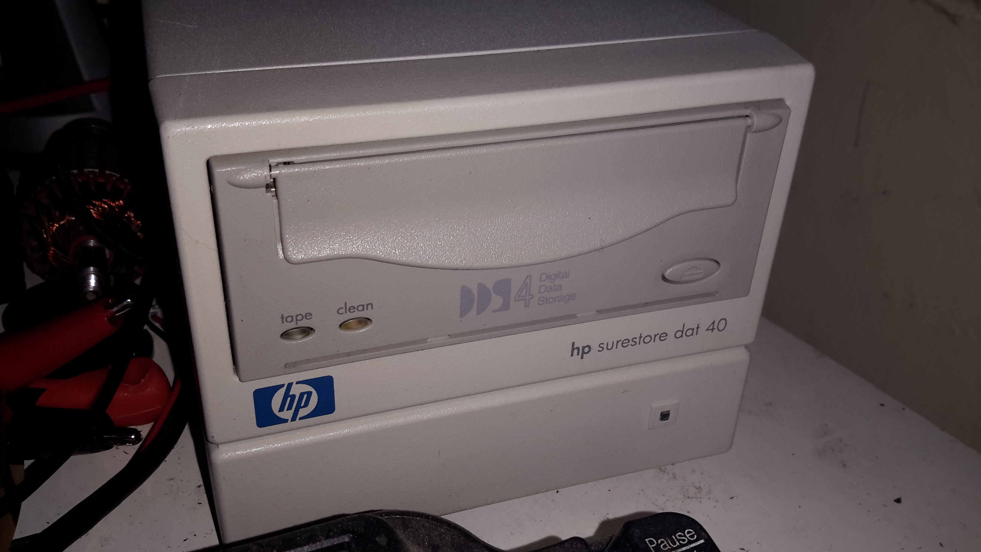
For the smaller stuff, like backing up the web server this very site runs on, another format seemed to suit better. Above is a HP DDS4 tape drive, which will store up to 40GB on a cassette compressed.
I picked this format since I already had some tapes, so it made sense.

Data Plate
Data Plate

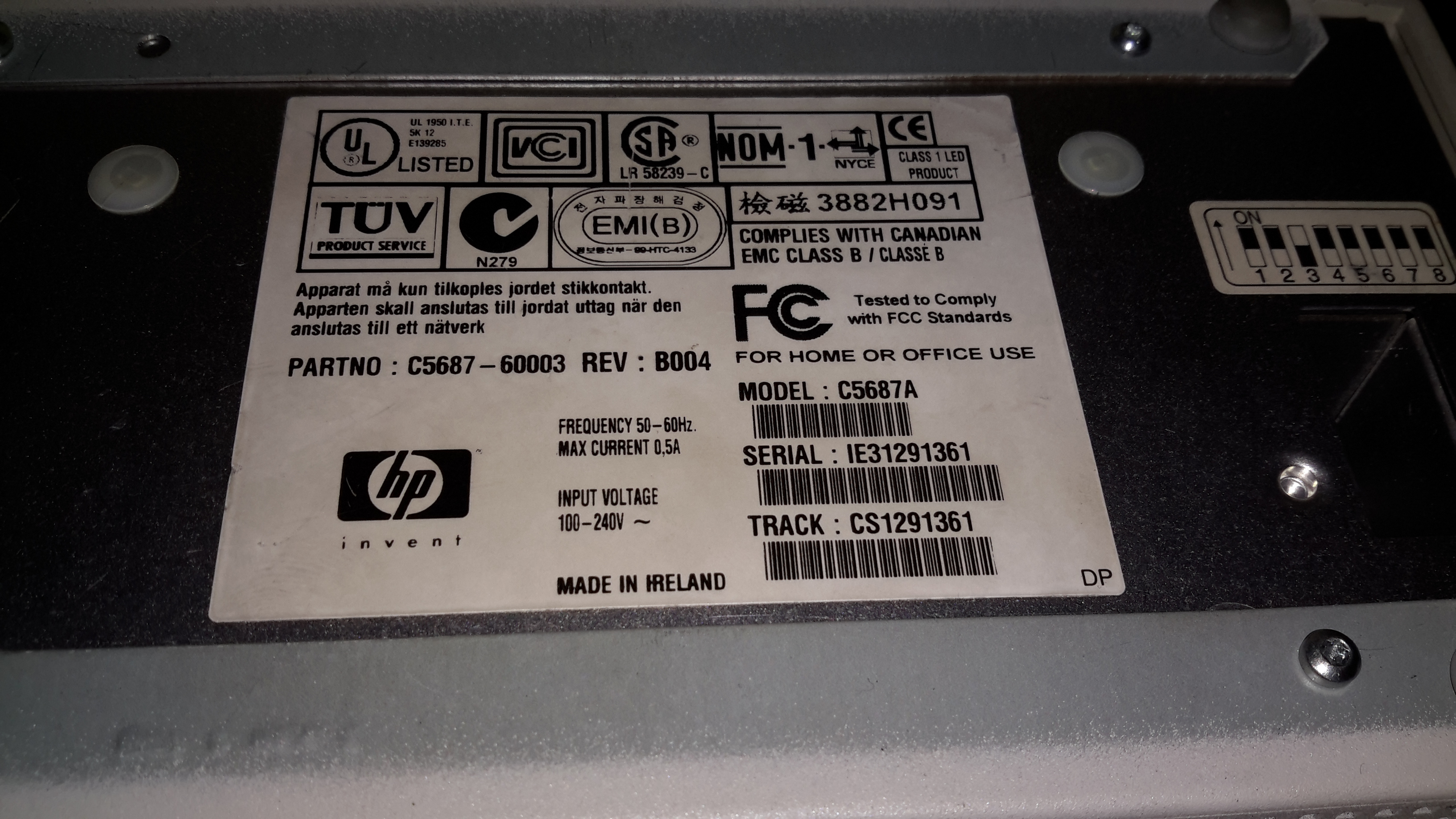
Here’s the info for those who want to know. It’s an older generation drive, mainly since the current generation of tape backup drives are hideously expensive, while the older ones are cheap & plentiful. Unfortunately the older generation of drives are all parallel SCSI, which can be a expensive & awkward to set up. Luckily I already have other parallel SCSI devices, so the support infrastructure for this drive was already in place.

Option Switches
Option Switches

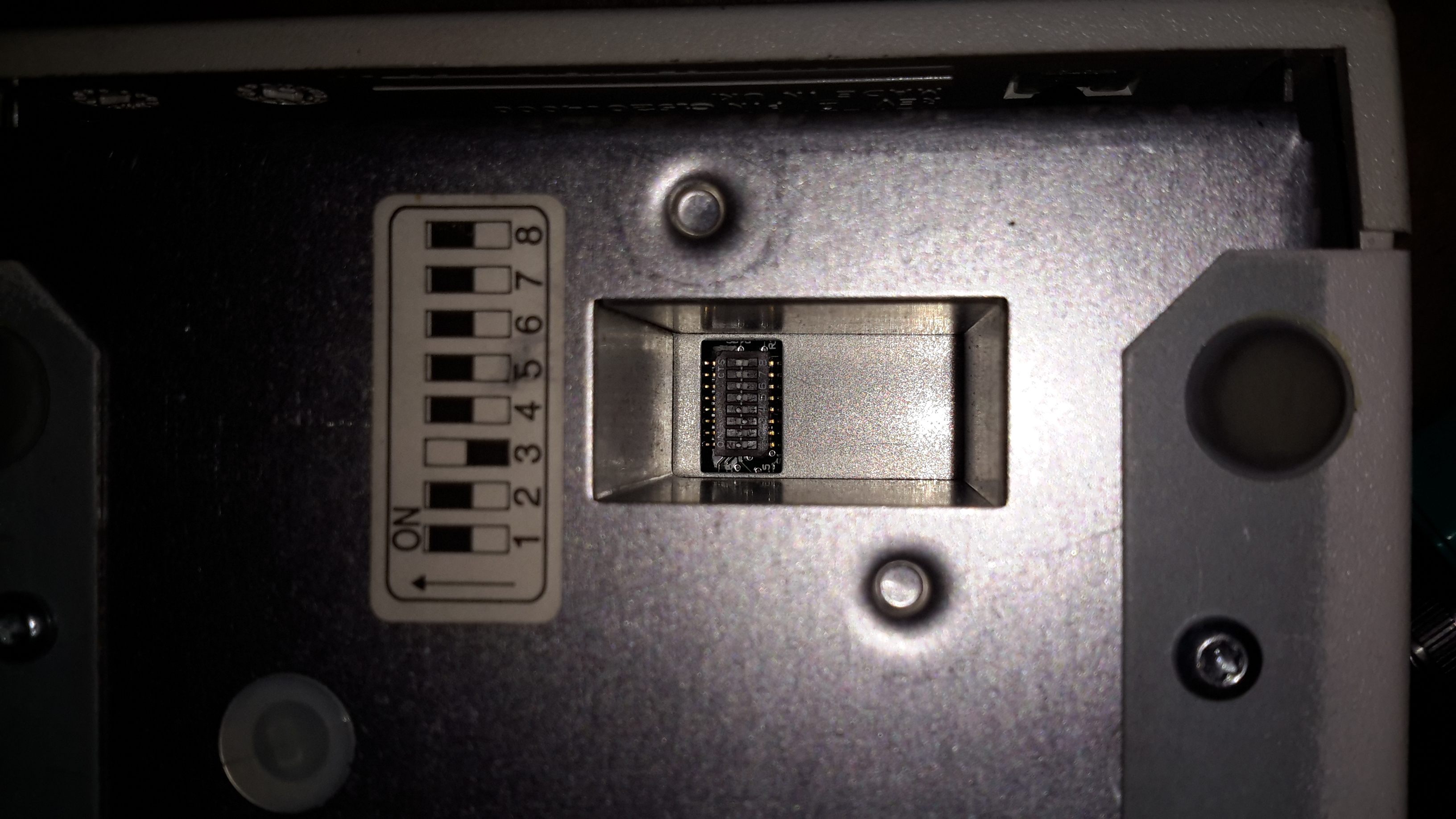
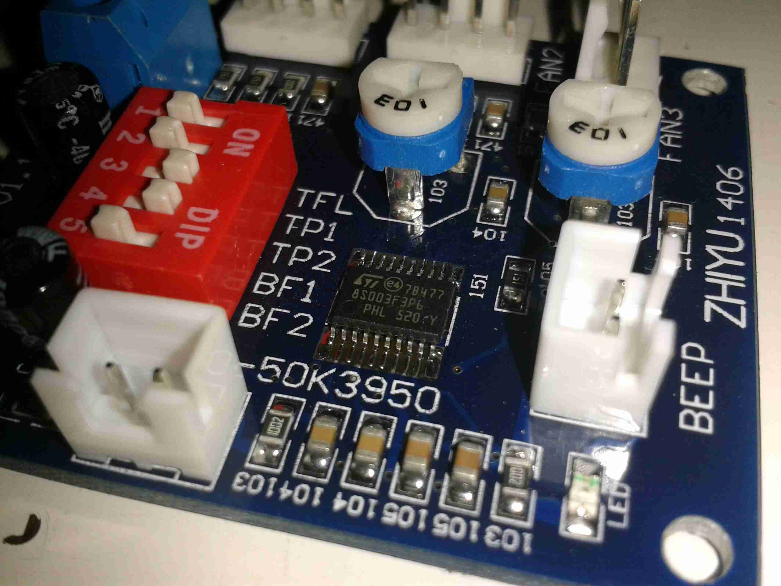
On the bottom of the drive is a bank of DIP switches, according to the manual these are for setting the drive for various flavours of UNIX operating systems. However it doesn’t go into what they actually change.

Controller PCB
Controller PCB

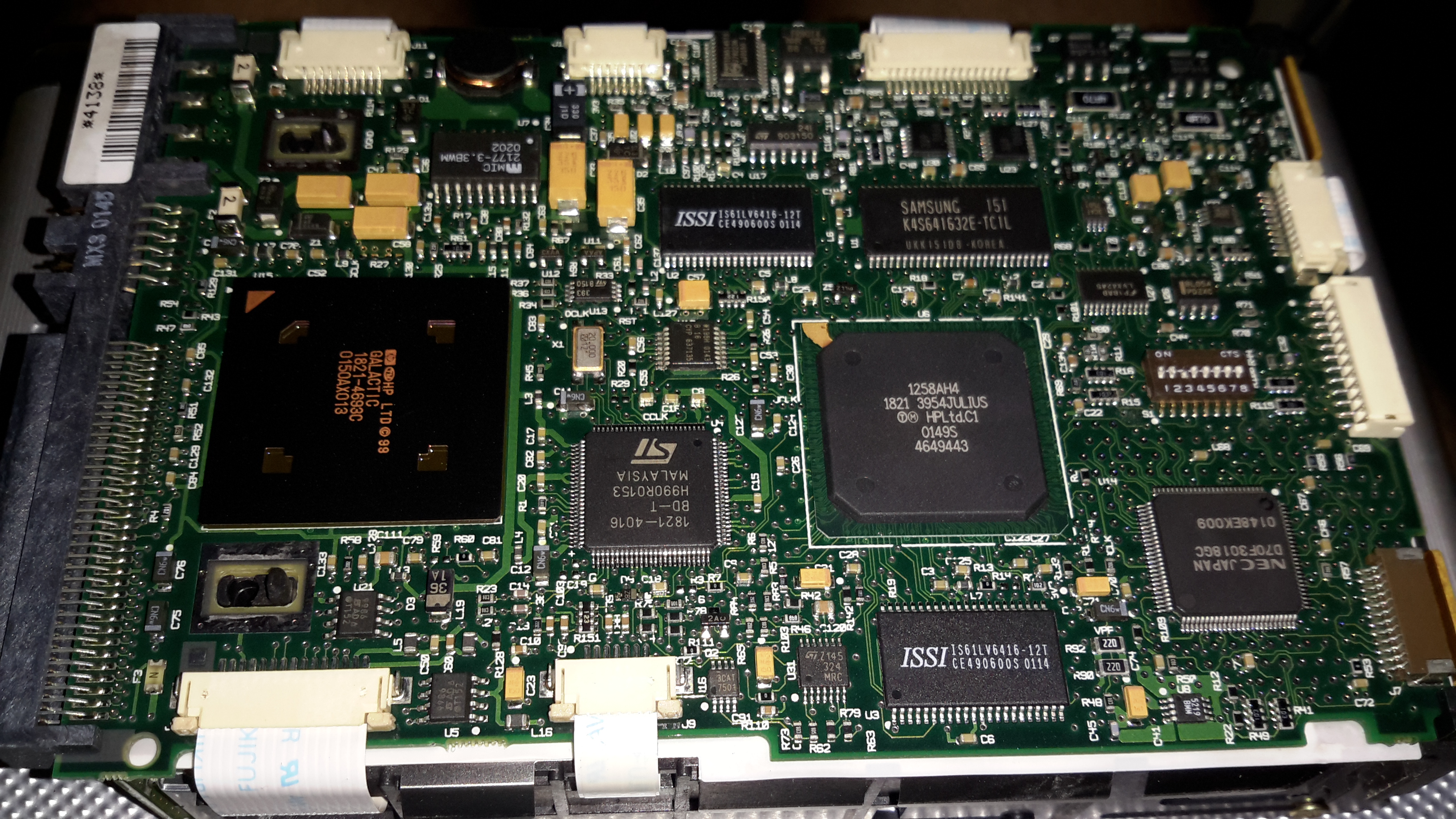
The bottom of the drive has the control PCB. The large IC on the left is the SCSI interface, I’ve seen this exact same chip on other SCSI tape drives. Centre is a SoC, like so many of these, not much information available.

Drive Frame
Drive Frame

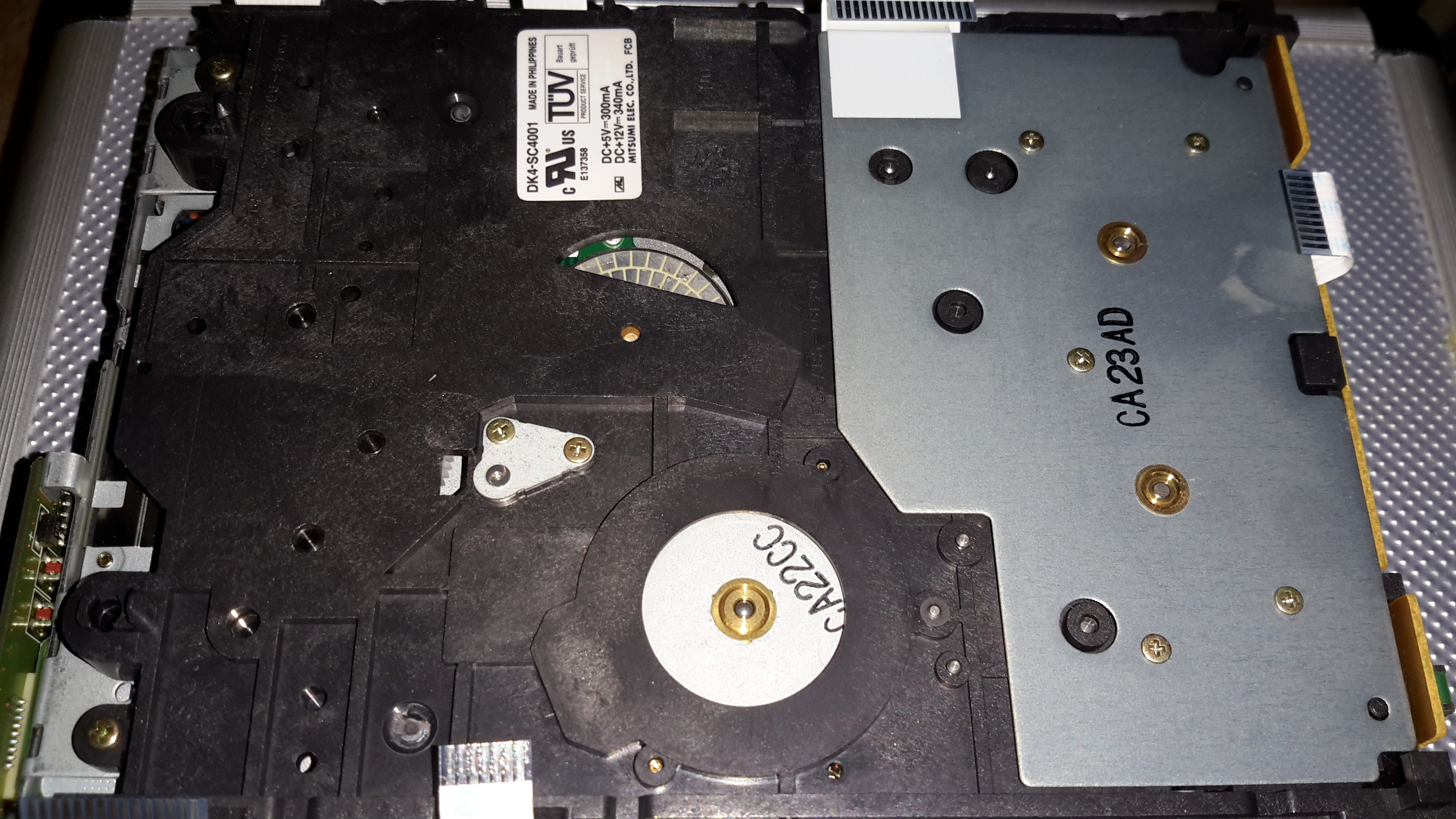
Removing the board doesn’t reveal much else, just the bottom of the frame with the tape spool motors on the right, capstan motor bottom centre. The bottom of the head drum motor is just peeping through the plastic top centre.

Head Drum
Head Drum

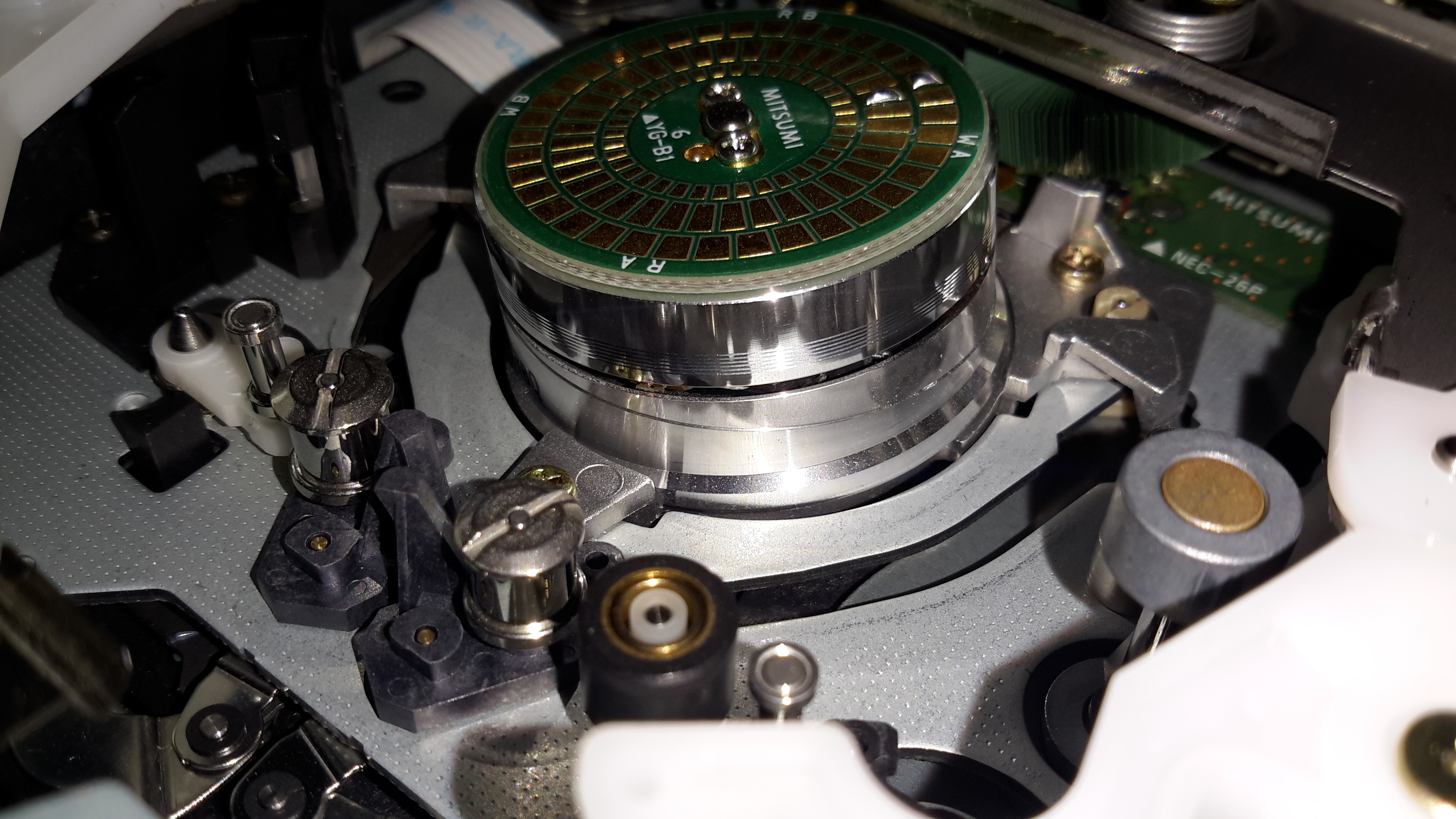
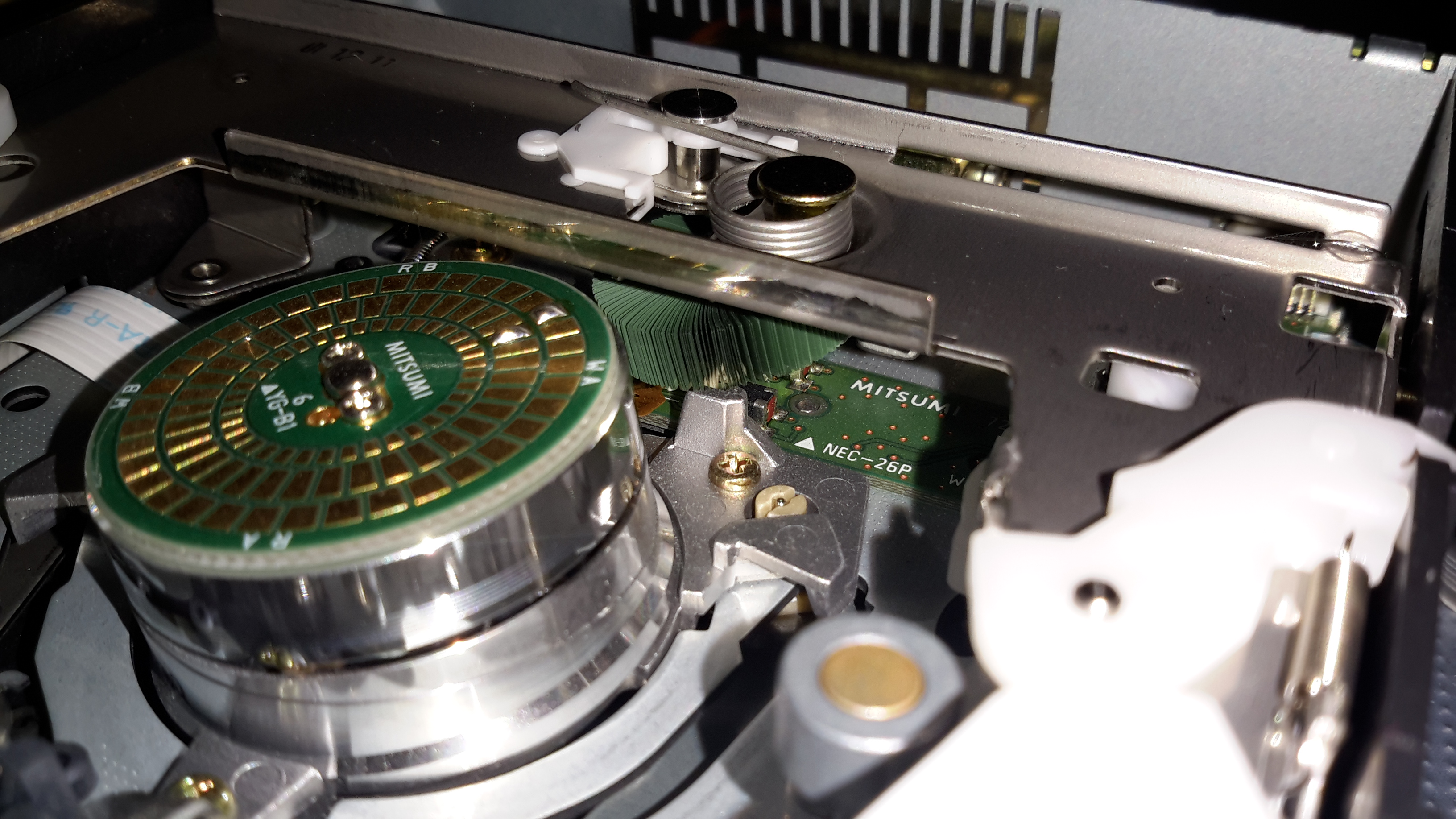
Here’s the head drum itself. These drives use a helical-scan flying head system, like old VHS tape decks. The top of the capstan motor is on the bottom right.

Cleaning Brush
Cleaning Brush

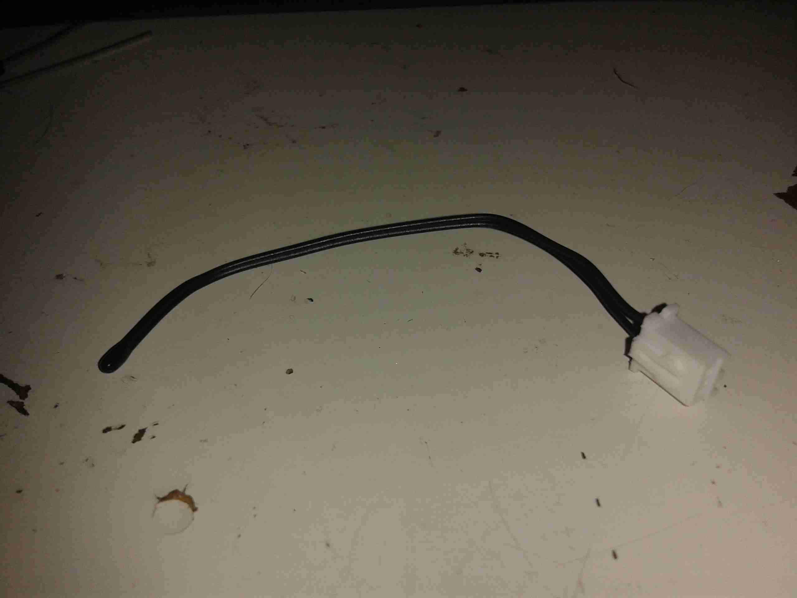
Hidden just under the tape transport frame is the head cleaning brush. I’m not sure exactly what this is made of, but it seems to be plastic.

Loading Motor
Loading Motor

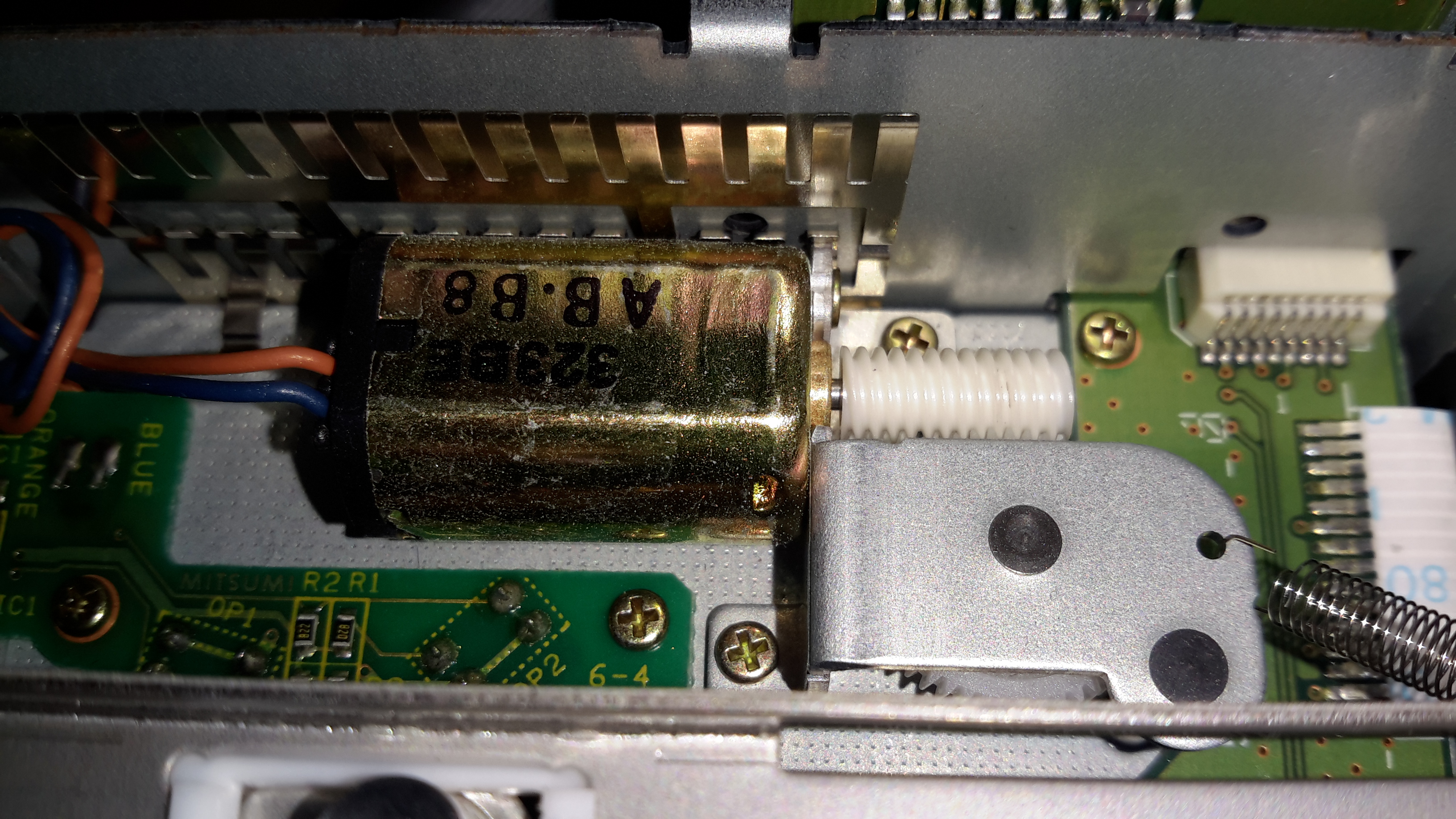
A single small DC motor with a worm drive handles all tape loading tasks. The PCB to the bottom left of the motor holds several break-beam sensors that tell the drive what position the transport is in.

Tape Transport Mech
Tape Transport Mech

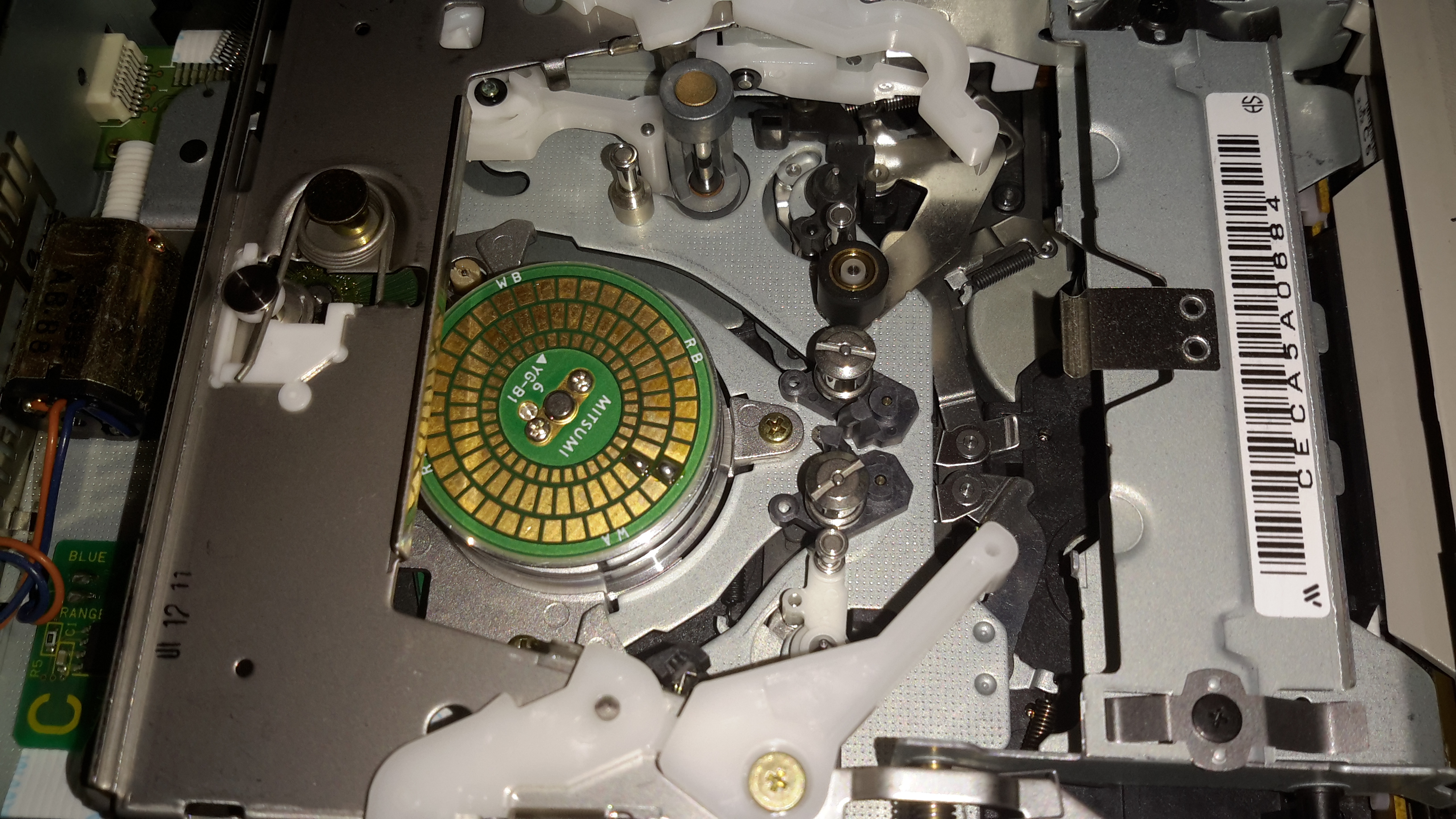
Here’s the overall tape transport. The PCB on top of the head drum is a novel idea: it’s sole purpose in life is to act as a substrate for solder blobs, used for balancing. As this drum spins at 11,400RPM when a DDS4 tape is in the drive, any slight imbalance would cause destructive vibration.

Tape Transport
Tape Transport

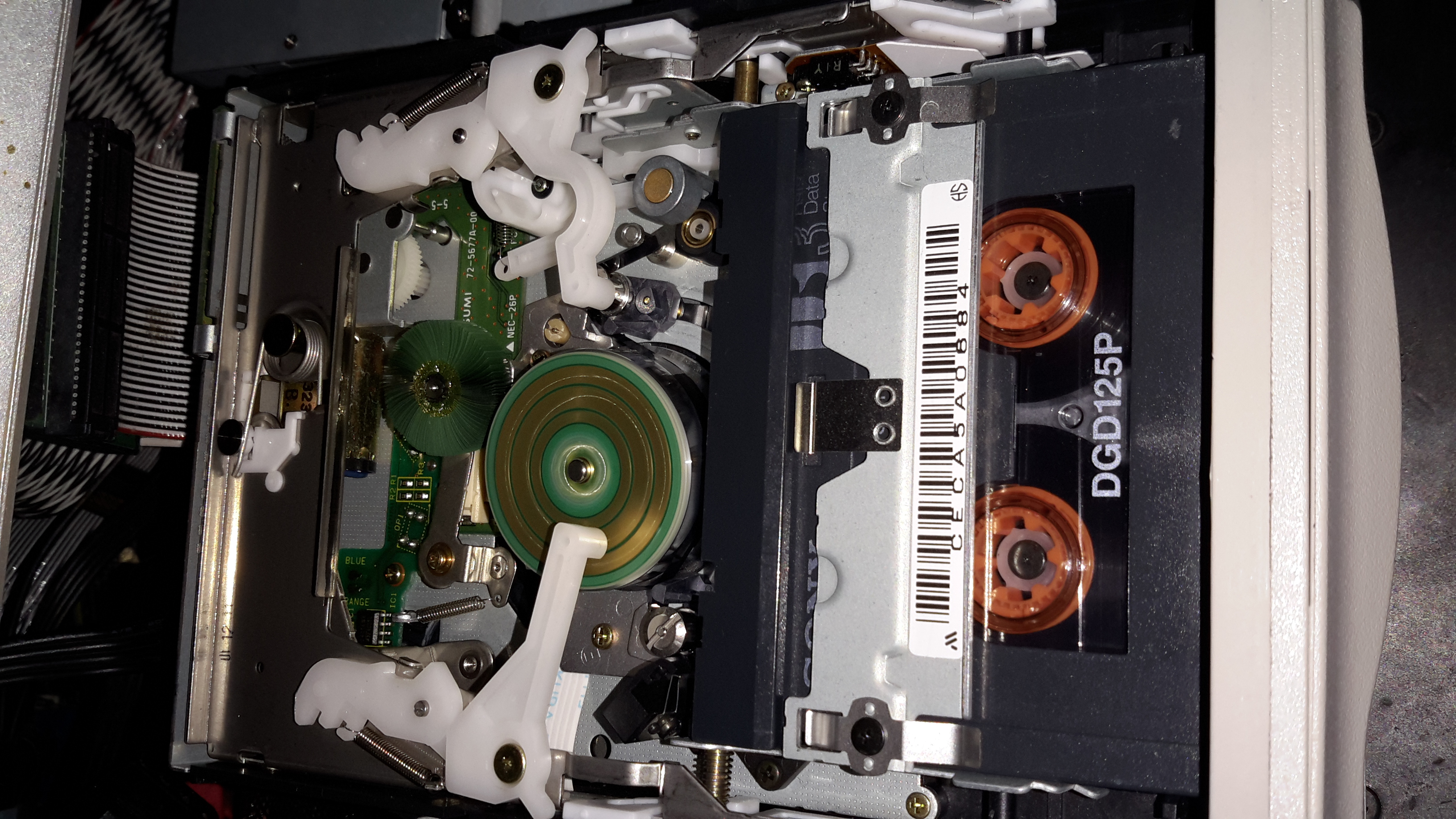
Here’s the drive active & writing a tape. (A daily backup of this web server actually). The green head cleaning brush can be better seen here. The drive constantly reads back what it writes to the tape, and if it detects an error, applies this brush momentarily to the drum to clean any shed oxide off the heads. The tape itself is threaded over all the guides, around the drum, then through the capstan & pinch roller.

Posted on Leave a comment

DIY SMPS Fan Speed Control – The Controllers

Finally, after a couple of weeks wait time, the fan controllers for the power supplies have arrived. They’re small boards, which is good for the small space left inside the case of the supply.

Controller Boards
Controller Boards

Here they are. I’m not certain what the pair of potentiometers are for – there’s no mention of them in the documentation. Possibly for calibration.
Beepers are supplied so an alarm can be heard if the fan fails – very useful for this application.

Controller Closeup
Controller Closeup

Here’s a closeup of the PCB. Options are set with the DIP switch bank on the left, details for that below. The main IC is a STM8S103F3 flash microcontroller.

Temperature Probe
Temperature Probe

The only issue at the moment is that the temperature probe leads are much too short. I’ll have to make a small modification to get enough length here.


Here’s all the details on the boards, more for future reference when they undoubtedly vanish from eBay 😉

Specifications

Working voltage:DC12V

Circuit load capacity: maximum current per output 5A, the bus currents up 9A

Output Range: The first channel 20% -100%, or 40% -100% (TFL = ON)
The second channel and the third channel 10% -100%

(Note: Above range only for PWM range, the actual control effect will vary depending on the fan.)

Temperature probe parameters: 50K B = 3950

Thermostat temperature zone error: error depending on the temperature probe, generally 3-5%

Stall alarm minimum speed: 700-800 rpm


Function setting switch Description:

TFL (No. 1): The lowest temperature channel PWM setting, when ON state FAN1 PWM minimum is 40%, when OFF the minimum PWM of FAN1 is 20%.

TP1 TP2 (No. 2,3): Temperature channel control temperature zones are interpreted as follows (need to used with the temperature probe):


TP1  TP2 Accelerating temperature Full speed temperature
OFF OFF 35℃ 45℃
ON OFF 40℃ 55℃
OFF ON 50℃ 70℃
ON ON 60℃ 90℃


When the temperature lower than the accelerated temperature, then output at the minimum rotation speed; when it exceed over the full temperature, then always output at full speed.

BF1 BF2 (No. 4,5): corresponds FAN1 FAN2 stall alarm function switch, when the corresponding open channel fan break down, the controller will alarm with soundand light (works with buzzle), alarm will automatically eliminated when the fan is rotated recovery . If BF1 and BF2 both are open (ON), the FAN1, FAN2 have any one or both stops, the controller will alarm!

Posted on Leave a comment

Amano PIX 3000x Timeclock

Front
Front

This is a late 90’s business timeclock, used for maintaining records of staff working times, by printing the time when used on a sheet of card.

Front Internal
Front Internal

Here is the top cover removed, which is normally locked in place to stop tampering. The unit is programmed with the 3 buttons & the row of DIP switches along the top edge.

Instructions
Instructions

Closeup of the settings panel, with all the various DIP switch options.

CPU & Display
CPU & Display

Cover plate removed from the top, showing the LCD & CPU board, the backup battery normally fits behind this. The CPU is a 4-bit microcontroller from NEC, with built in LCD driver.

PSU & Drivers
PSU & Drivers

Power Supply & prinhead drivers. This board is fitted with several NPN Darlington transistor arrays for driving the dox matrix printhead.

Printhead
Printhead

Printhead assembly itself. The print ribbon fits over the top of the head & over the pins at the bottom. The drive hammers & solenoids are housed in the circular top of the unit.

Printhead Bottom
Printhead Bottom

Bottom of the print head showing the row of impact pins used to create the printout.

2013-02-13 18.00.09Bottom of the solenoid assembly with the ribbon cable for power. There are 9 solenoids, to operate the 9 pins in the head.

Return Spring
Return Spring

Top layer of the printhead assembly, showing the leaf spring used to hold the hammers in the correct positions.

Hammers
Hammers

Hammer assembly. The fingers on the ends of the arms push on the pins to strike through the ribbon onto the card.

Solenoids
Solenoids

The ring of solenoids at the centre of the assembly. These are driven with 3A darlington power arrays on the PSU board.

Gearbox Internals
Gearbox Internals

There is only a single drive motor in the entire unit, that both clamps the card for printing & moves the printhead laterally across the card. Through a rack & pinion this also advances the ribbon with each print.


Posted on Leave a comment

Raspberry Pi GPIO Experiment Board Improvements

First Mods
First Mods

Here are the first set of mods & improvements to the RasPi Experiment board. Instead of the solder-point experiment space, I have added a standard mini-breadboard, even though it’s a little too long to fit on the board properly.

In the DIP breakout, is a MAX232 TTL-RS232 interface IC, useful for interfacing directly to the Pi’s UART, made available on the GPIO breakout. I will be hardwiring the MAX232 IC into the GPIO port, & fitting headers to the relevant pins on the IC breakout to make interfacing to the Pi easier.

All the MAX232 requires to operate are a 5v supply & 4 1µF capacitors.

The new TO220 device next to the breadboard is a TIP121 darlington power transistor.This is rated at 80v 5A continuous. Useful for driving large loads from a GPIO output.


More to come soon!