Finally, after a couple of weeks wait time, the fan controllers for the power supplies have arrived. They’re small boards, which is good for the small space left inside the case of the supply.
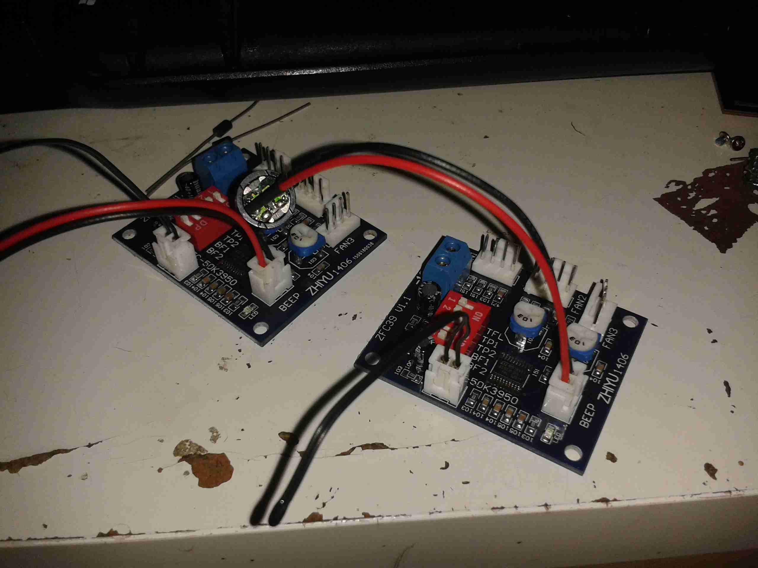
Here they are. I’m not certain what the pair of potentiometers are for – there’s no mention of them in the documentation. Possibly for calibration.
Beepers are supplied so an alarm can be heard if the fan fails – very useful for this application.
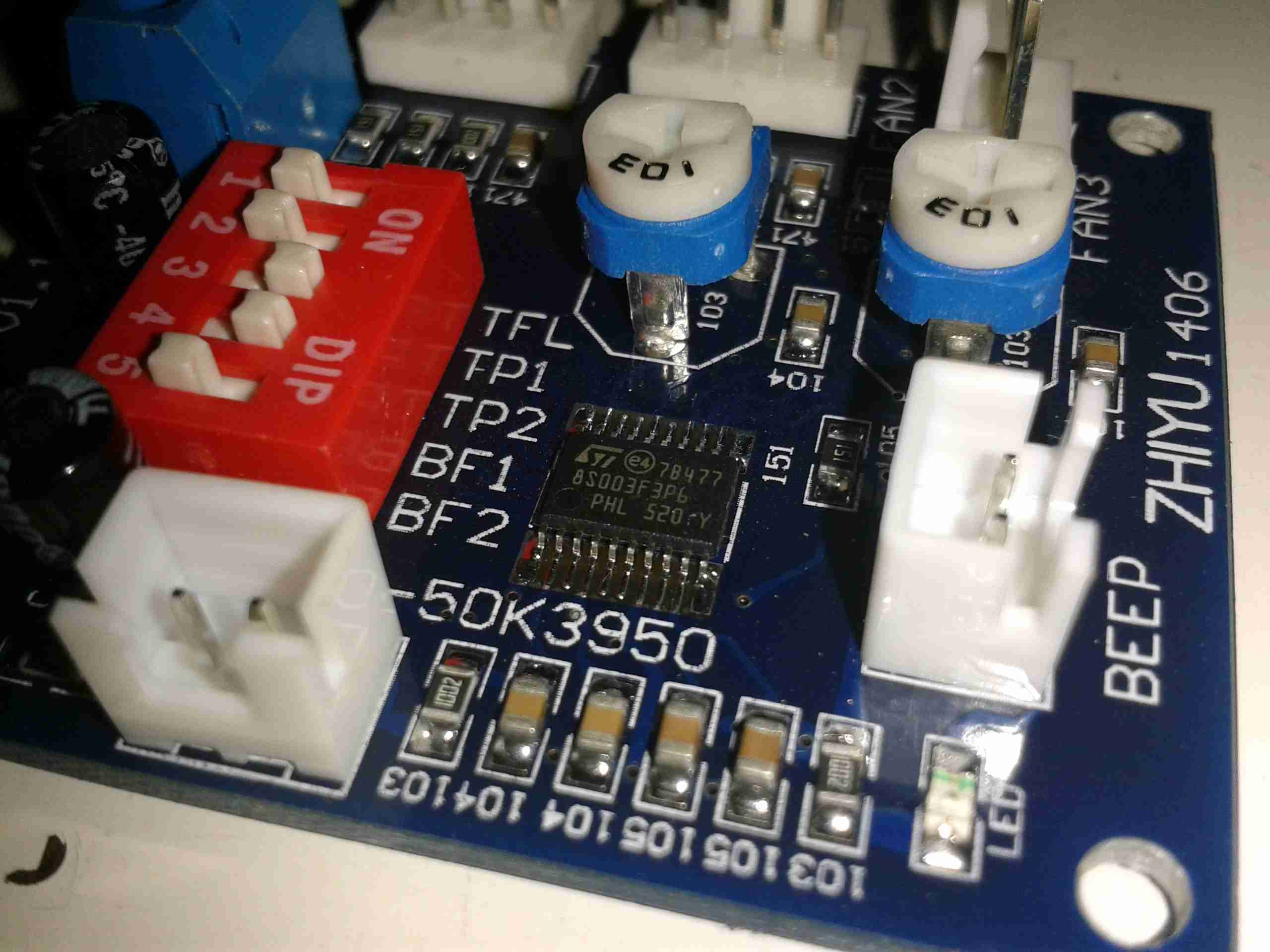
Here’s a closeup of the PCB. Options are set with the DIP switch bank on the left, details for that below. The main IC is a STM8S103F3 flash microcontroller.
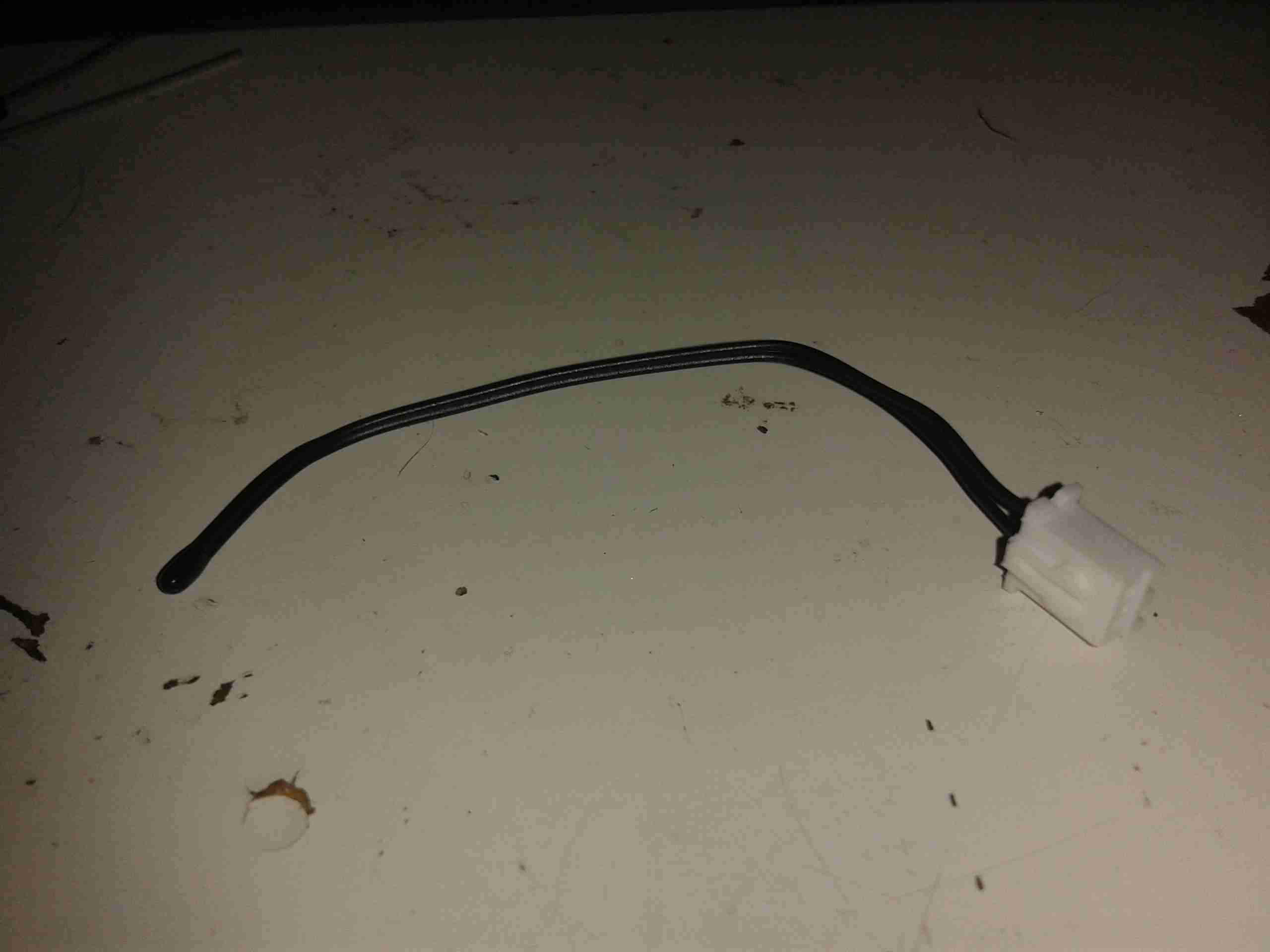
The only issue at the moment is that the temperature probe leads are much too short. I’ll have to make a small modification to get enough length here.
Here’s all the details on the boards, more for future reference when they undoubtedly vanish from eBay 😉
Specifications
Working voltage:DC12V
Circuit load capacity: maximum current per output 5A, the bus currents up 9A
Output Range: The first channel 20% -100%, or 40% -100% (TFL = ON)
The second channel and the third channel 10% -100%
(Note: Above range only for PWM range, the actual control effect will vary depending on the fan.)
Temperature probe parameters: 50K B = 3950
Thermostat temperature zone error: error depending on the temperature probe, generally 3-5%
Stall alarm minimum speed: 700-800 rpm
Function setting switch Description:
TFL (No. 1): The lowest temperature channel PWM setting, when ON state FAN1 PWM minimum is 40%, when OFF the minimum PWM of FAN1 is 20%.
TP1 TP2 (No. 2,3): Temperature channel control temperature zones are interpreted as follows (need to used with the temperature probe):
| TP1 | TP2 | Accelerating temperature | Full speed temperature |
| OFF | OFF | 35℃ | 45℃ |
| ON | OFF | 40℃ | 55℃ |
| OFF | ON | 50℃ | 70℃ |
| ON | ON | 60℃ | 90℃ |
When the temperature lower than the accelerated temperature, then output at the minimum rotation speed; when it exceed over the full temperature, then always output at full speed.
BF1 BF2 (No. 4,5): corresponds FAN1 FAN2 stall alarm function switch, when the corresponding open channel fan break down, the controller will alarm with soundand light (works with buzzle), alarm will automatically eliminated when the fan is rotated recovery . If BF1 and BF2 both are open (ON), the FAN1, FAN2 have any one or both stops, the controller will alarm!
