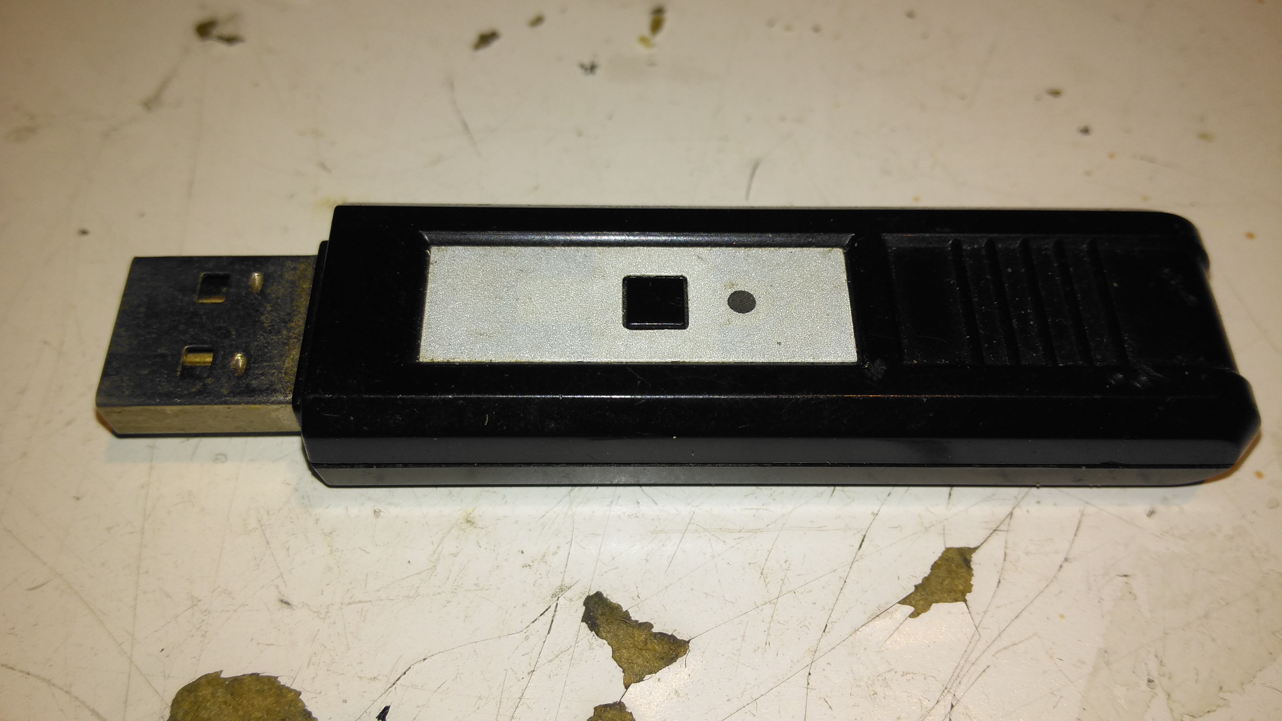
This is a pair of modules that Maplin was selling some time back, to send stereo audio over a 2.4GHz radio link. The transmitter identifies as a USB sound card, I’ve personally used these units to transmit audio about 60ft. The transmitter, above, has a single button for pairing with the receiver below.
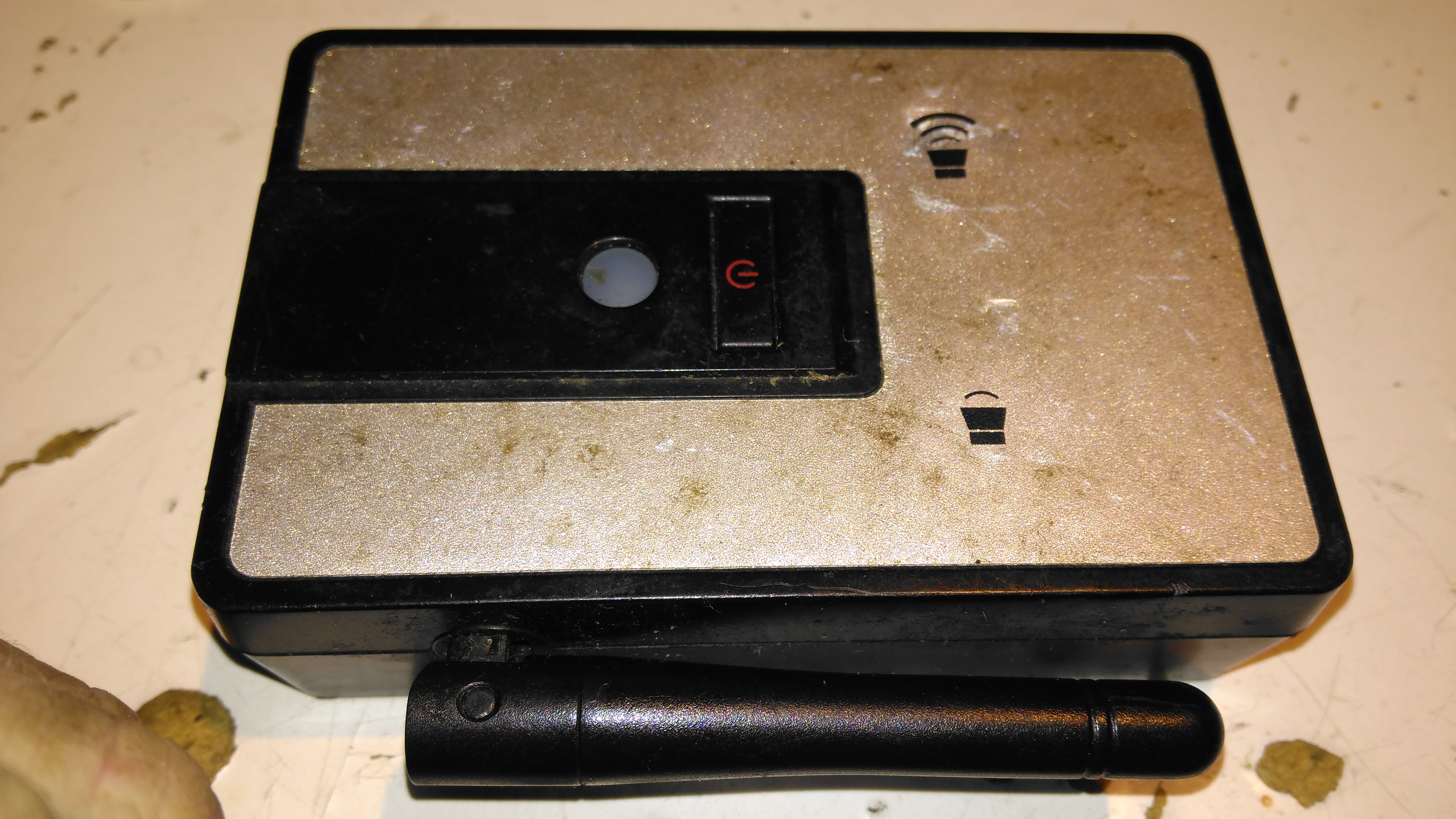
Receiver
The receiver unit has a large external antenna, a link status LED & volume buttons, these directly control the volume level on the host PC via the sound card drivers.
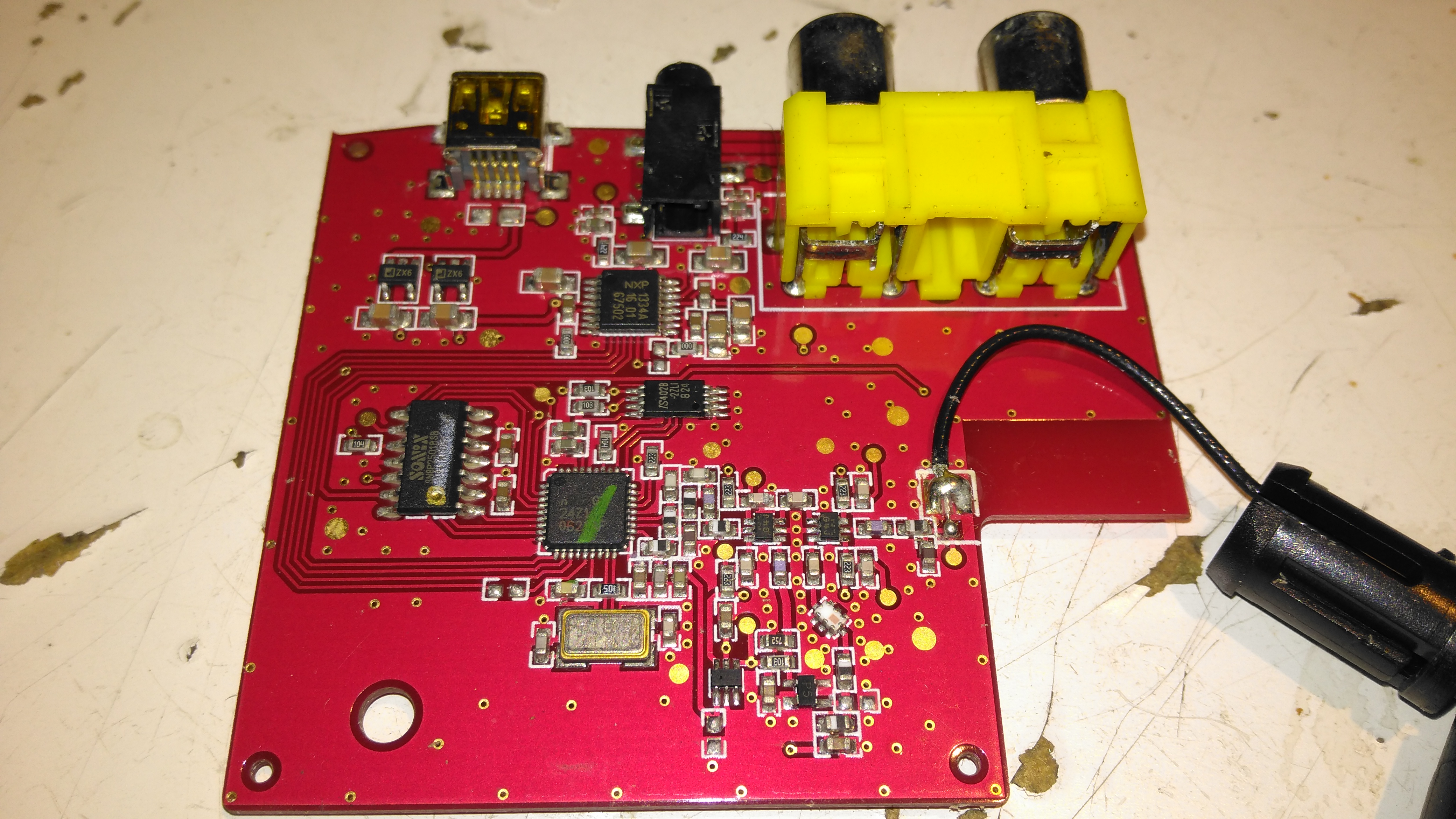
Receiver PCB Top
Popping the case open on the receiver reveals a large PCB, holding the chipset, along with the audio output jacks & Mini-USB power input. The antenna Coax is soldered to the PCB.
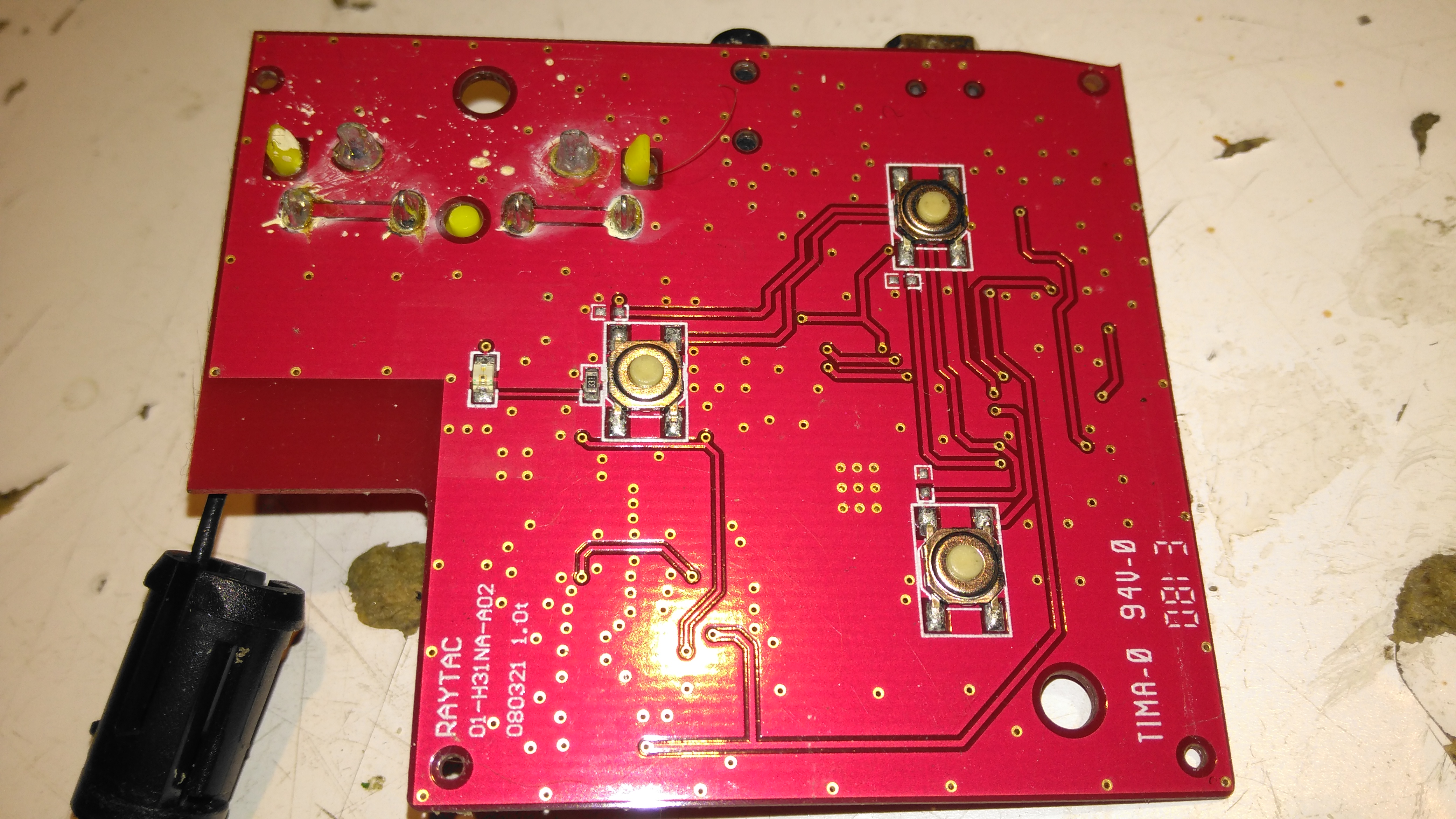
Receiver PCB Bottom
The top of the board has the control buttons, and the status LED.
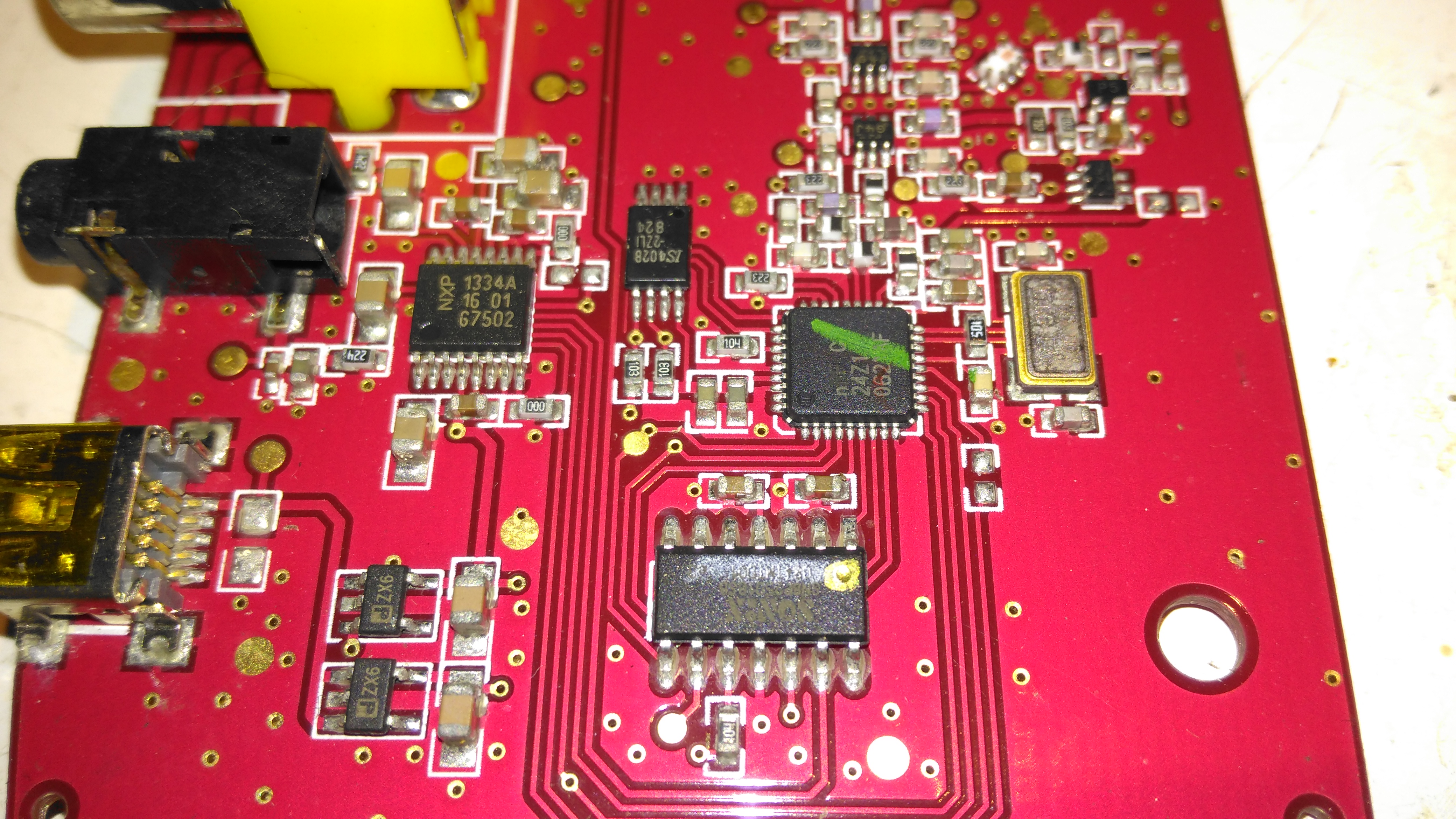
Receiver Chipset
The chipset used here is a Nordic Semiconductor nRF20Z01 2.4GHz Stereo Audio Streamer, there’s a small microcontroller which does all the register magic on the RF transceiver. The RF chain is at the top of the photo, audio outputs on the top left, and the micro USB power input & voltage regulators at bottom left.
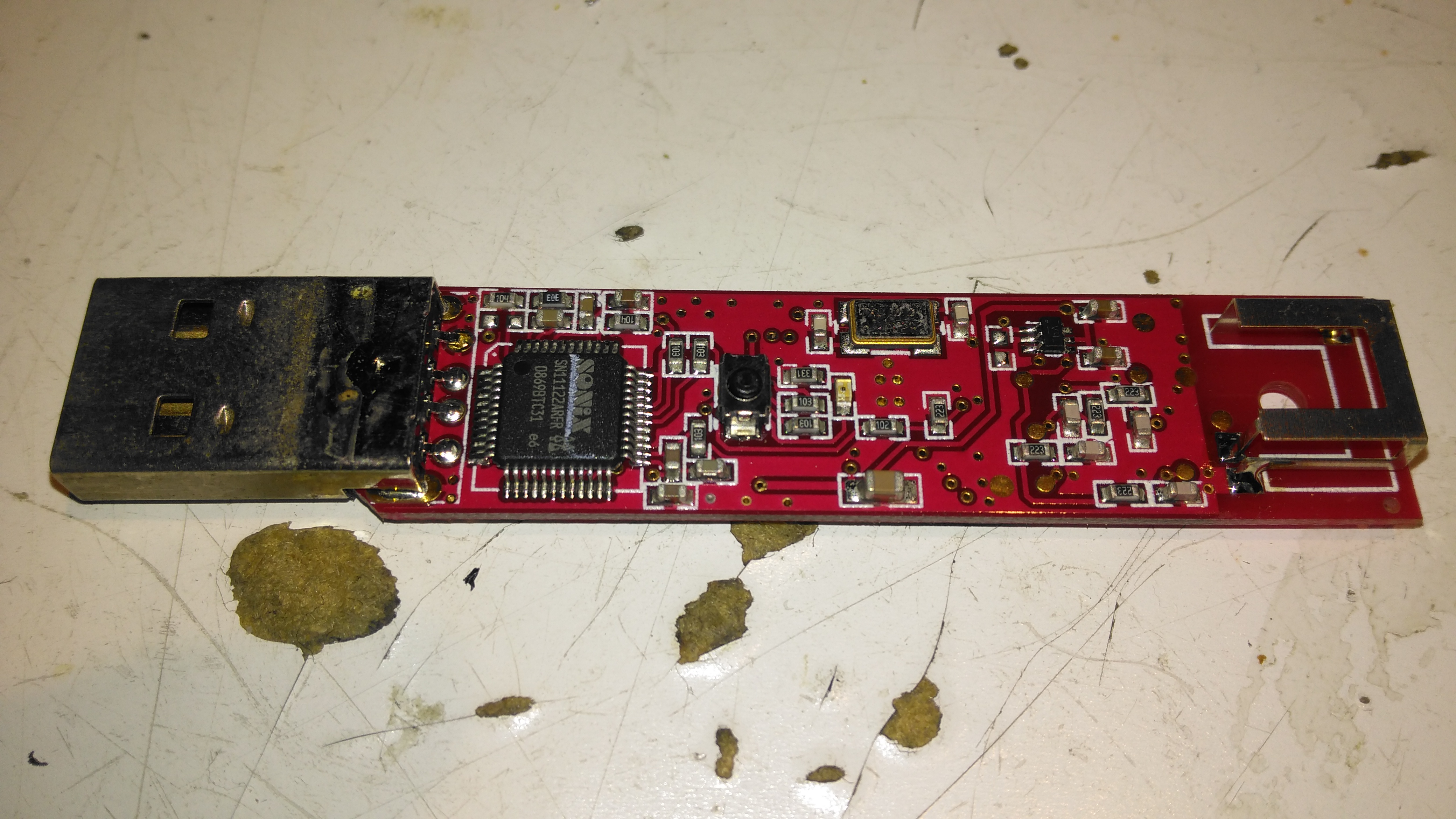
Transmitter PCB Top
The transmitter PCB has a Sonix USB Audio Codec, to interface with the host PC. This is then fed into another Nordic Semi part on the opposite side of the board:
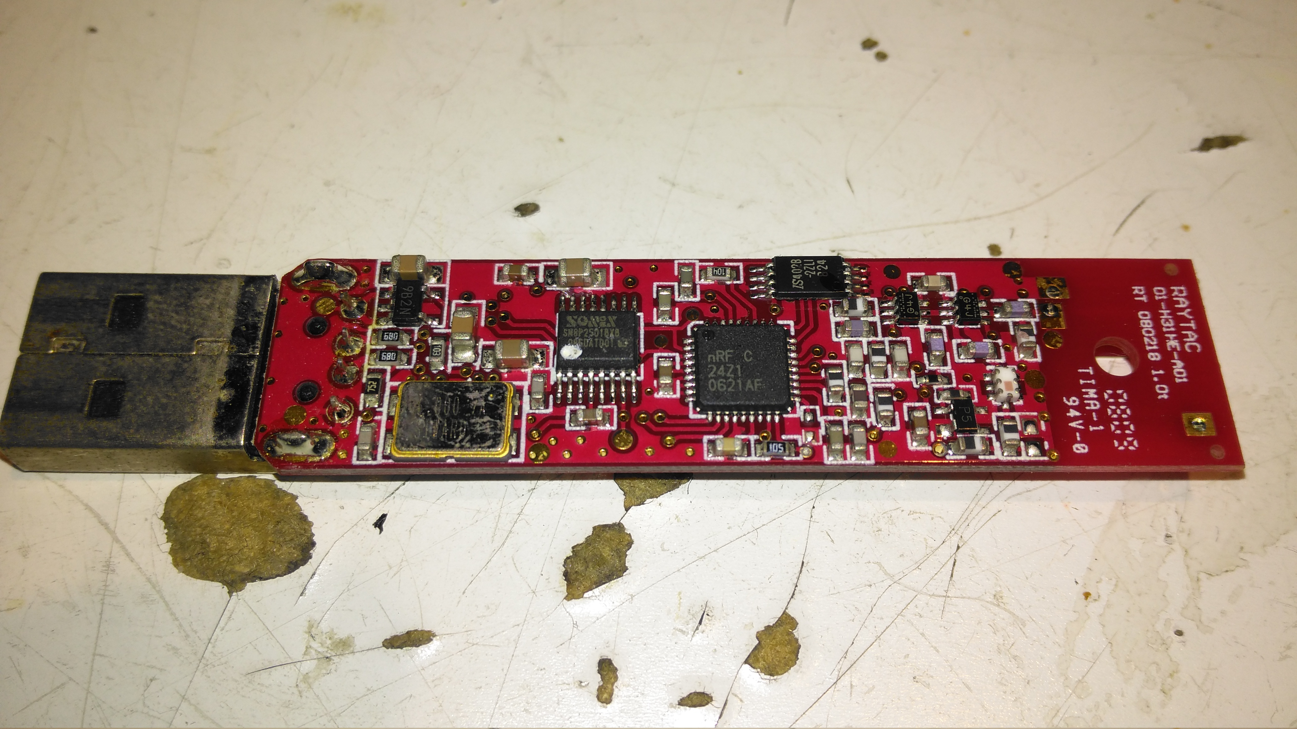
Transmitter PCB Bottom
The bottom of the transmitter has the RF section, and another small control microcontroller.
It’s been 4 months since I did a rejig of my storage server, installing a new 16-port SATA HBA to support the disk drives. I mentioned the factory fan the card came with in my previous post, and I didn’t have many hopes of it surviving long.
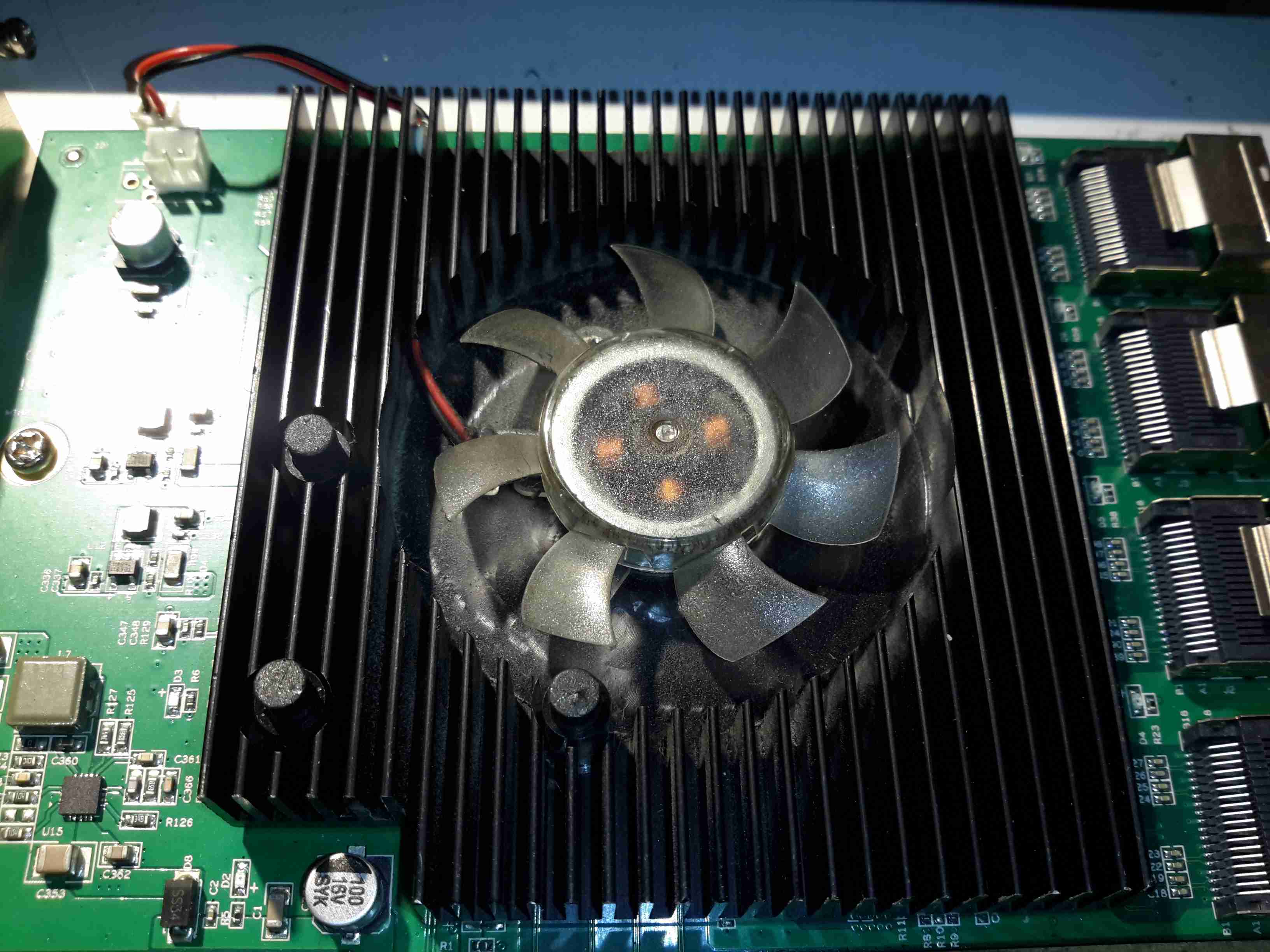
Heatsink
The heatsink card has barely had enough time to accumulate any grime from the air & the fan has already failed!
There’s no temperature sensing or fan speed sensing on this card, so a failure here could go unnoticed, and under load without a fan the heatsink becomes hot enough to cause burns. (There are a total of 5 large ICs underneath it). This would probably cause the HBA to overheat & fail rather quickly, especially when under a high I/O load, with no warning. In my case, the bearings in the fan failed, so the familiar noise of a knackered sleeve bearing fan alerted me to problems.
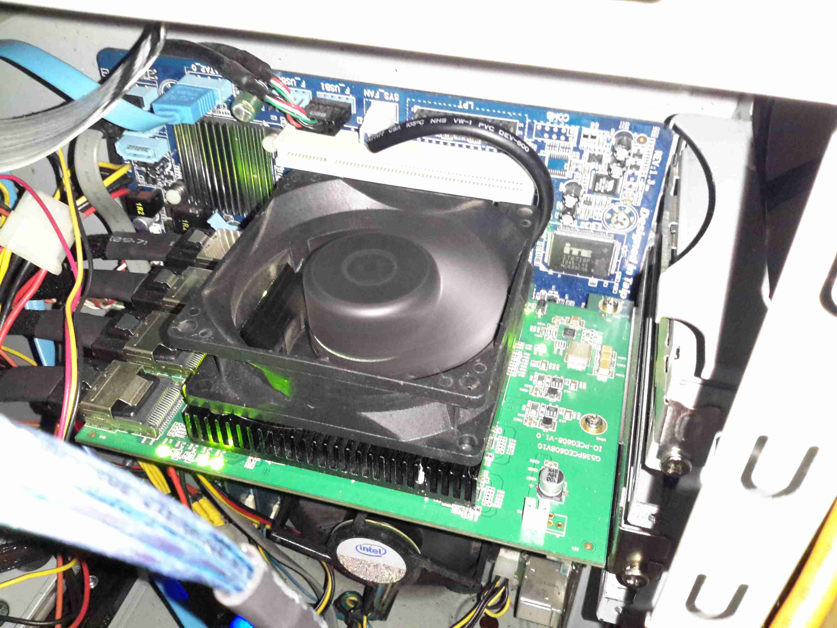
Replacement Fan
A replacement 80mm Delta fan has been attached to the heatsink in place of the dead fan, and this is plugged into a motherboard fan header, allowing sensing of the fan speed. The much greater airflow over the heatsink has dramatically reduced running temperatures. The original fan probably had it’s bearings cooked by the heat from the card as it’s airflow capability was minimal.
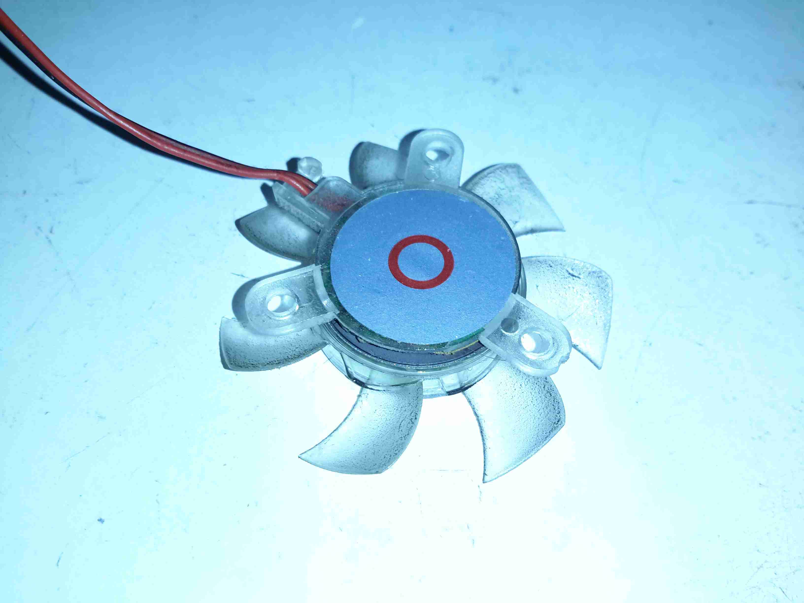
Fan Rear
Here’s the old fan removed from the heatsink. The back label, usally the place where I’d expect to find some specifications has nothing but a red circle. This really is the cheapest crap that the manufacturer could have fitted, and considering this HBA isn’t exactly cheap, I’d expect better.
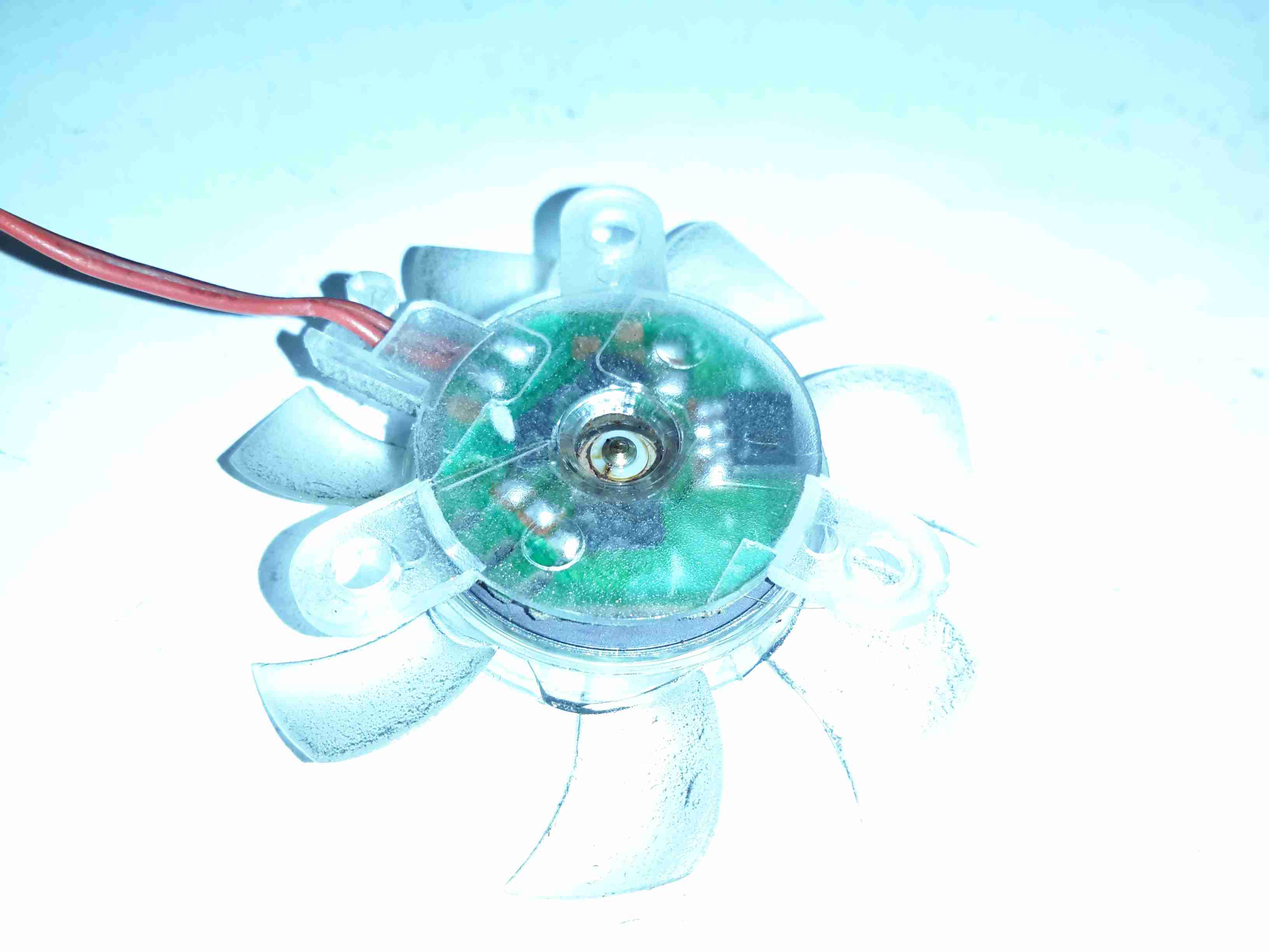
Bearings
Peeling off the back label reveals the back of the bearing housing, with the plastic retaining clip. There’s some sign of heat damage here, the oil has turned into gum, all the lighter fractions having evaporated off.
Rotor
The shaft doesn’t show any significant damage, but since the phosphor bronze bearing is softer, there is some dirt in here which is probably a mix of degraded oil & bearing material.
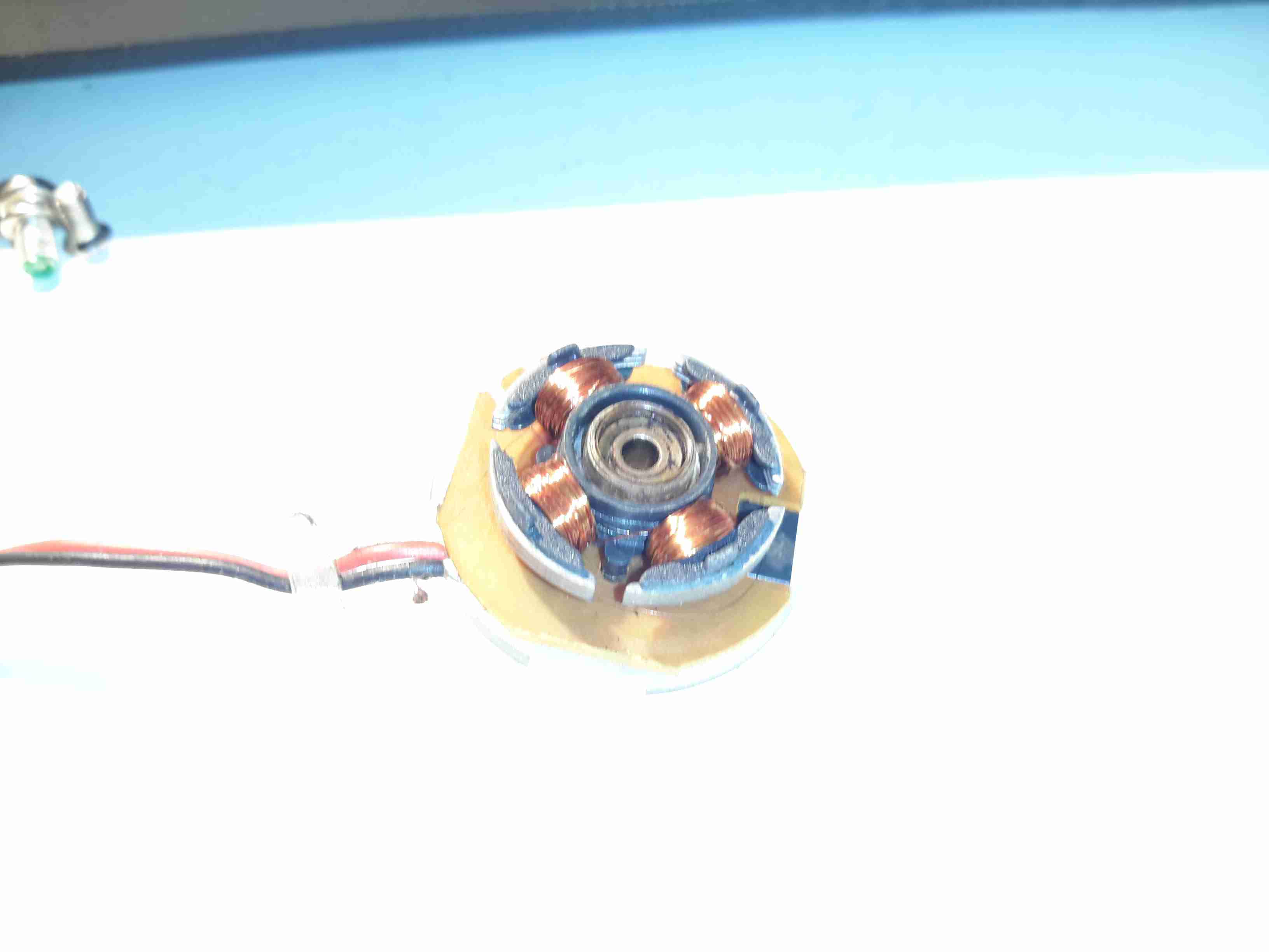
Stator & Bearing
There’s more gunge around the other end of the bearing & it’s been worn enough that side play can be felt with the shaft. In ~3000 hours running this fan is totally useless.
For some time now I’ve been running a large disk array to store all the essential data for my network. The current setup has 10x 4TB disks in a RAID6 array under Linux MD.
Up until now the disks have been running in external Orico 9558U3 USB3 drive bays, through a PCIe x1 USB3 controller. However in this configuration there have been a few issues:
Congestion over the USB3 link. RAID rebuild speeds were severely limited to ~20MB/s in the event of a failure. General data transfer was equally as slow.
Drive dock general reliability. The drive bays are running a USB3 – SATA controller with a port expander, a single drive failure would cause the controller to reset all disks on it’s bus. Instead of losing a single disk in the array, 5 would disappear at the same time.
Cooling. The factory fitted fans in these bays are total crap – and very difficult to get at to change. A fan failure quickly allows the disks to heat up to temperatures that would cause failure.
Upgrade options difficult. These bays are pretty expensive for what they are, and adding more disks to the USB3 bus would likely strangle the bandwidth even further.
Disk failure difficult to locate. The USB3 interface doesn’t pass on the disk serial number to the host OS, so working out which disk has actually failed is difficult.
To remedy these issues, a proper SATA controller solution was required. Proper hardware RAID controllers are incredibly expensive, so they’re out of the question, and since I’m already using Linux MD RAID, I didn’t need a hardware controller anyway.
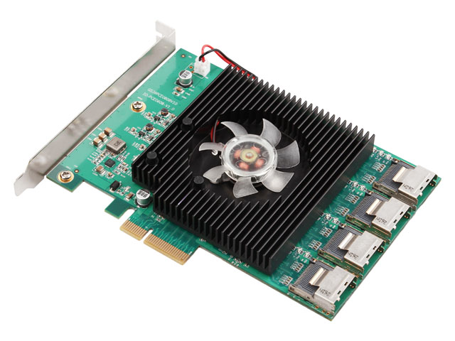
16-Port HBA
A quick search for suitable HBA cards showed me the IOCrest 16-port SATAIII controller, which is pretty low cost at £140. This card breaks out the SATA ports into standard SFF-8086 connectors, with 4 ports on each. Importantly the cables to convert from these server-grade connectors to standard SATA are supplied, as they’re pretty expensive on their own (£25 each).
This card gives me the option to expand the array to 16 disks eventually, although the active array will probably be kept at 14 disks with 2 hot spares, this will give a total capacity of 48TB.
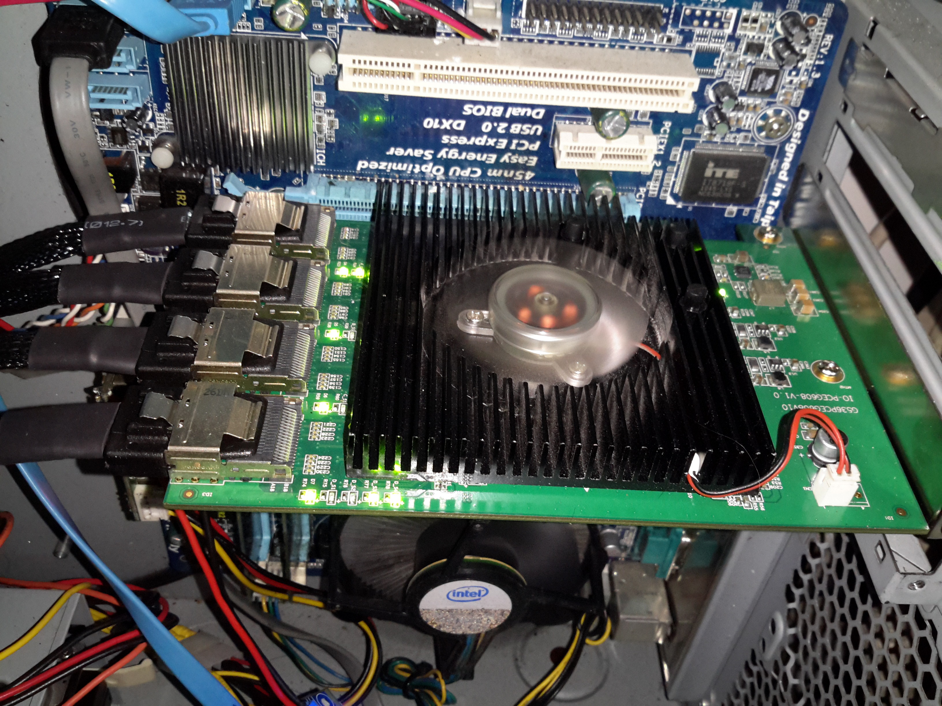
SATA HBA
Here’s the card installed in the host machine, with the array running. One thing I didn’t expect was the card to be crusted with activity LEDs. There appears to be one LED for each pair of disks, plus a couple others which I would expect are activity on the backhaul link to PCIe. (I can’t be certain, as there isn’t any proper documentation anywhere for this card. It certainly didn’t come with any ;)).
I’m not too impressed with the fan that’s on the card – it’s a crap sleeve bearing type, so I’ll be keeping a close eye on this for failure & will replace with a high quality ball-bearing fan when it finally croaks. The heatsink is definitely oversized for the job, with nothing installed above the card barely gets warm, which is definitely a good thing for life expectancy.
Update 10/02/17 – The stock fan is now dead as a doornail after only 4 months of continuous operation. Replaced with a high quality ball-bearing 80mm Delta fan to keep things running cool. As there is no speed sense line on the stock fan, the only way to tell it was failing was by the horrendous screeching noise of the failing bearings.
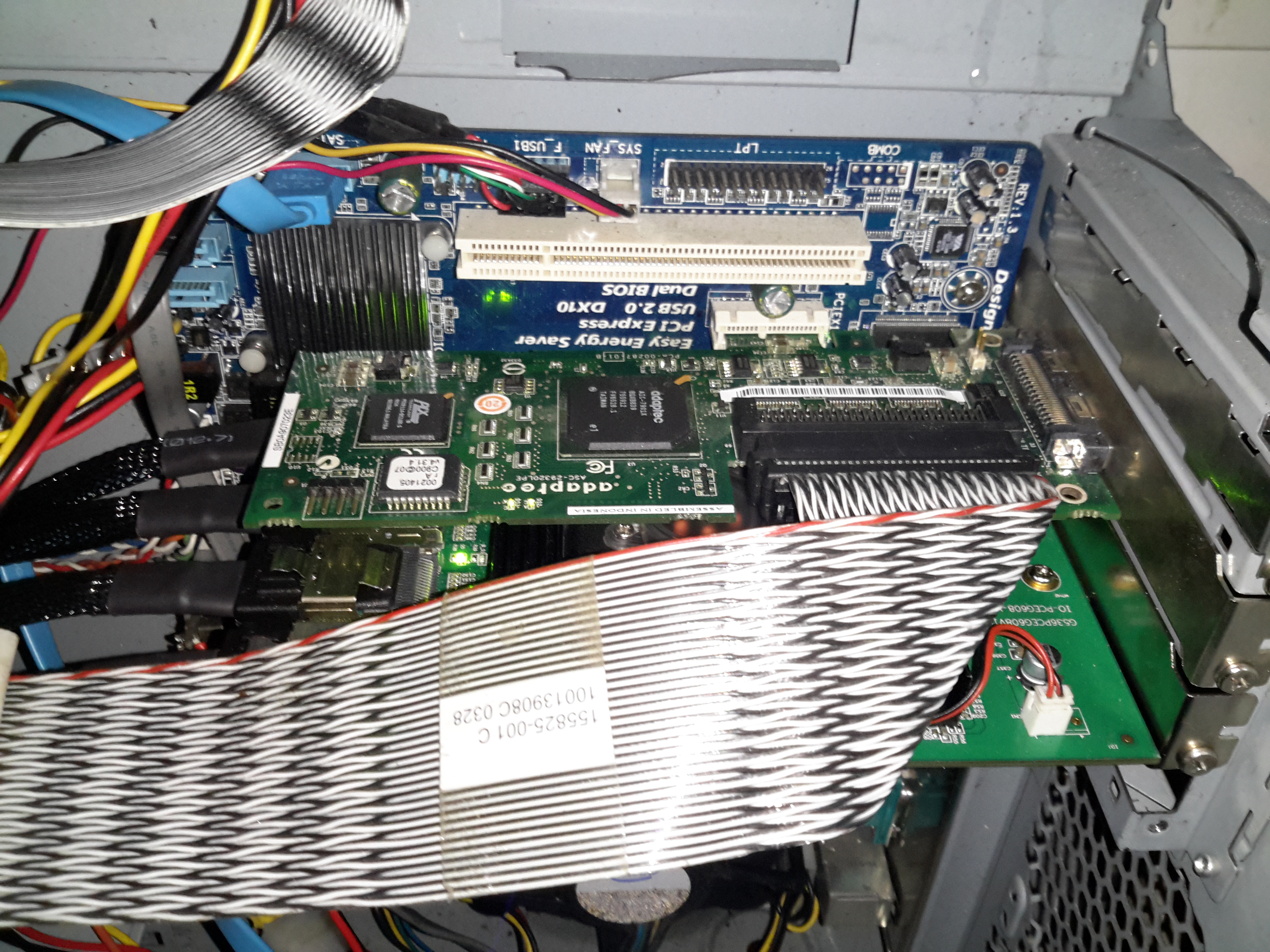
SCSI Controller
Above is the final HBA installed in the PCIe x1 slot above – a parallel SCSI U320 card that handles the tape backup drives. This card is very close to the cooling fan of the SATA card, and does make it run warmer, but not excessively warm. Unfortunately the card is too long for the other PCIe socket – it fouls on the DIMM slots.
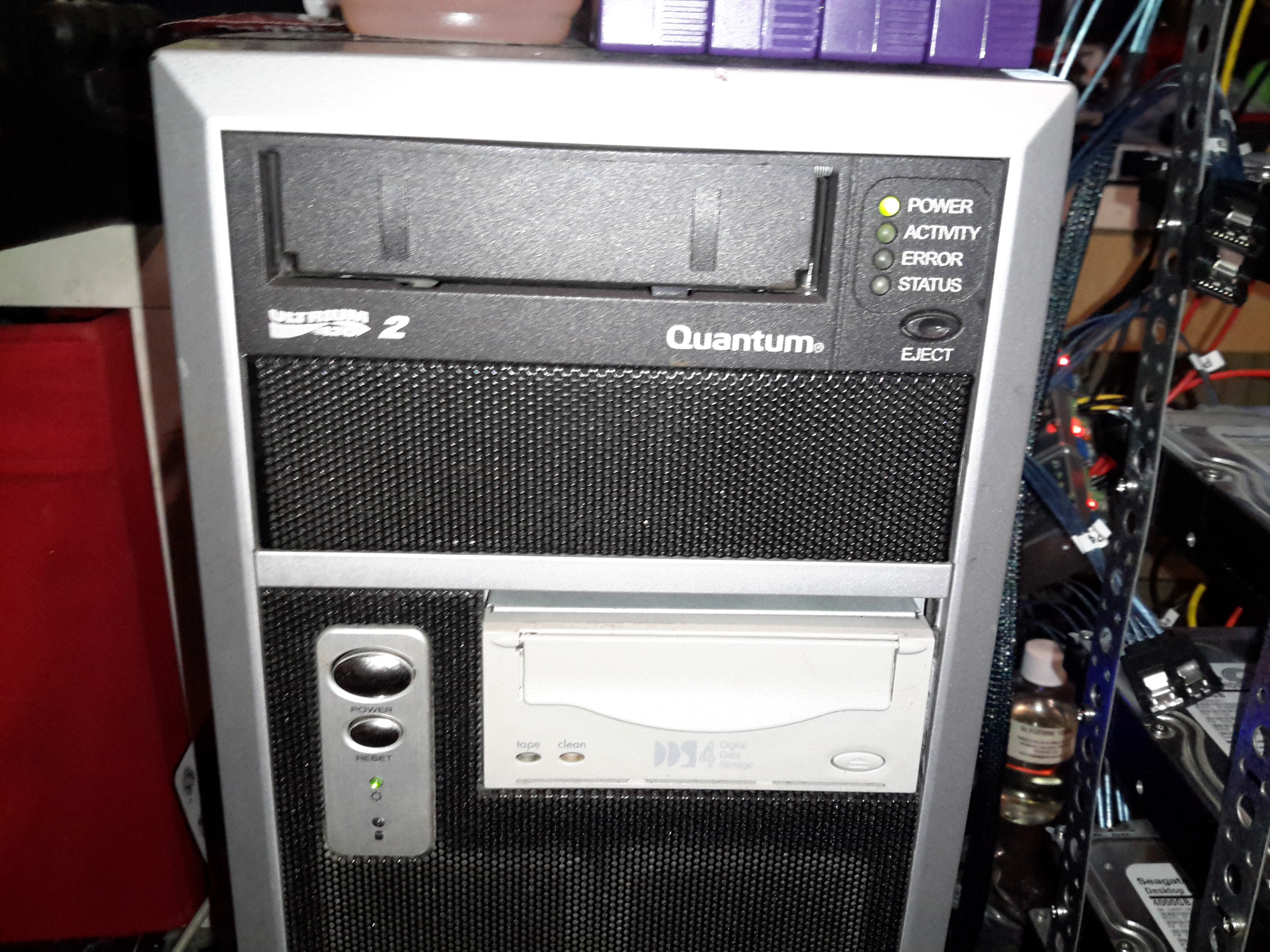
Backup Drives
The tape drives are LTO2 300/600GB for large file backup & DDS4 20/40GB DAT for smaller stuff. These were had cheap on eBay, with a load of tapes. Newer LTO drives aren’t an option due to cost.
The main disk array is currently built as 9 disks in service with a single hot spare, in case of disk failure, this gives a total size after parity of 28TB:
/dev/md0:
        Version : 1.2
  Creation Time : Wed Mar 11 16:01:01 2015
     Raid Level : raid6
     Array Size : 27348211520 (26081.29 GiB 28004.57 GB)
  Used Dev Size : 3906887360 (3725.90 GiB 4000.65 GB)
   Raid Devices : 9
  Total Devices : 10
    Persistence : Superblock is persistent

  Intent Bitmap : Internal

    Update Time : Mon Nov 14 14:28:59 2016
          State : active
 Active Devices : 9
Working Devices : 10
 Failed Devices : 0
  Spare Devices : 1

         Layout : left-symmetric
     Chunk Size : 64K

           Name : Main-PC:0
           UUID : 266632b8:2a8a3dd3:33ce0366:0b35fad9
         Events : 773938

    Number   Major   Minor   RaidDevice State
       0       8       48        0      active sync   /dev/sdd
       1       8       32        1      active sync   /dev/sdc
       9       8       96        2      active sync   /dev/sdg
      10       8      112        3      active sync   /dev/sdh
      11       8       16        4      active sync   /dev/sdb
       5       8      176        5      active sync   /dev/sdl
       6       8      144        6      active sync   /dev/sdj
       7       8      160        7      active sync   /dev/sdk
       8       8      128        8      active sync   /dev/sdi

      12       8        0        -      spare   /dev/sda
The disks used are Seagate ST4000DM000 Desktop HDDs, which at this point have ~15K hours on them, and show no signs of impending failure.
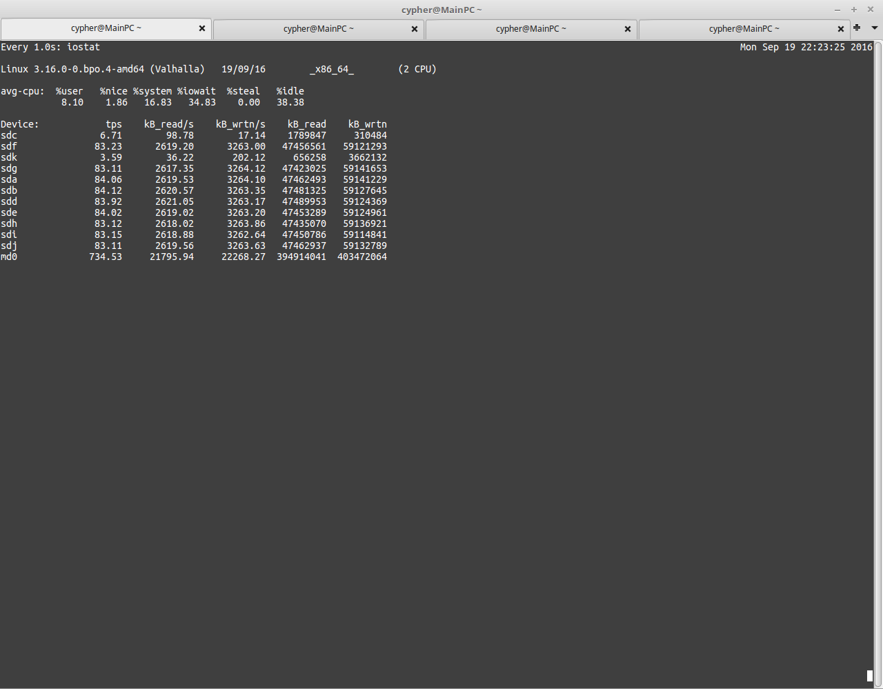
USB3 Speeds
Here’s a screenshot with the disk array fully loaded running over USB3. The aggregate speed on the md0 device is only 21795KB/s. Extremely slow indeed.
This card is structured similarly to the external USB3 bays – a PCI Express bridge glues 4 Marvell 9215 4-port SATA controllers into a single x8 card. Bus contention may become an issue with all 16 ports used, but as far with 9 active devices, the performance increase is impressive. Adding another disk to the active array would certainly give everything a workout, as rebuilding with an extra disk will hammer both read from the existing disks & will write to the new.
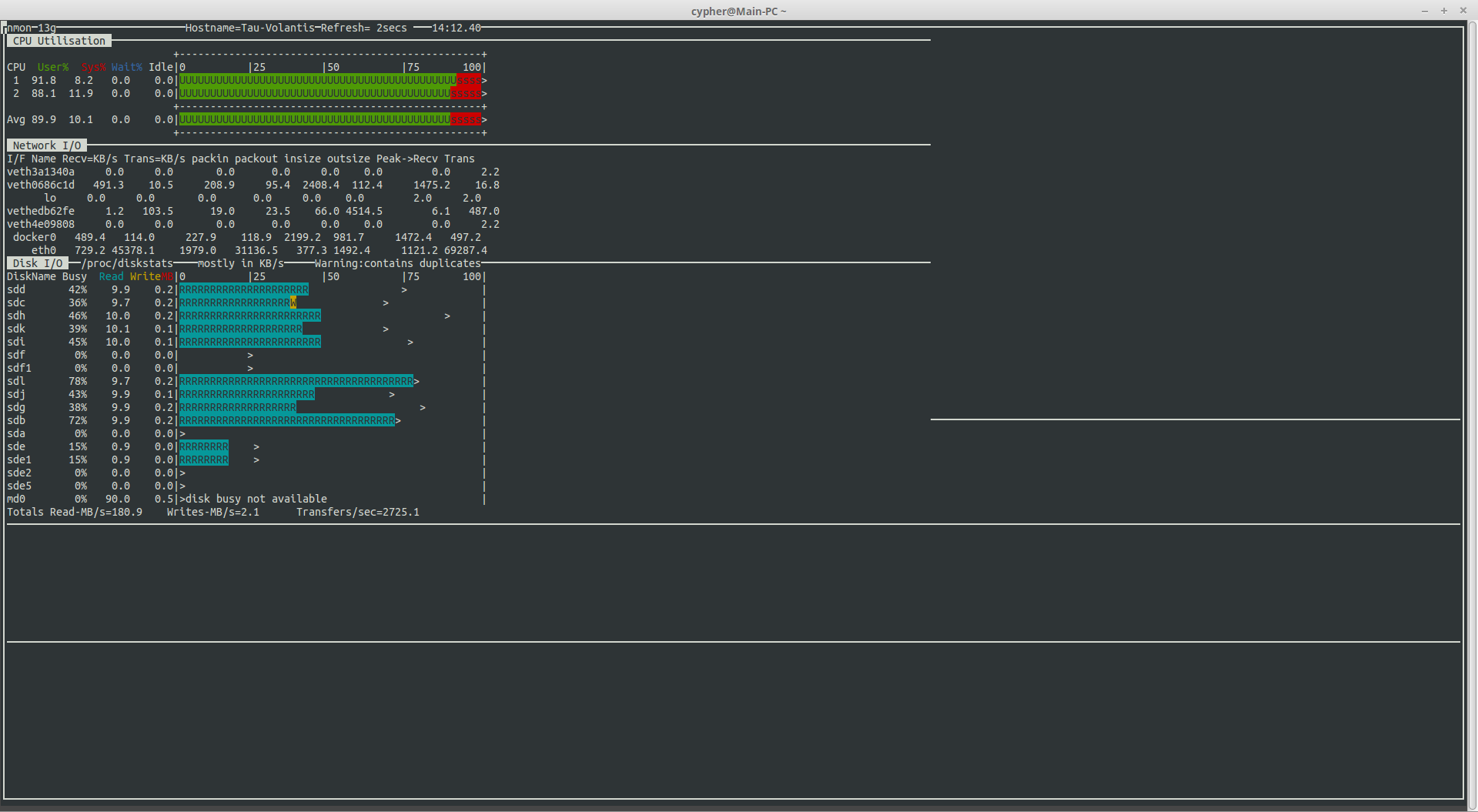
HBA Speeds
With all disks on the new controller, I’m sustaining read speeds of 180MB/s. (Pulling data off over the network). Write speeds are always going to be pretty pathetic with RAID6, as parity calculations have to be done. With Linux MD, this is done by the host CPU, which is currently a Core2Duo E7500 at 2.96GHz, with this setup, I get 40-60MB/s writes to the array with large files.
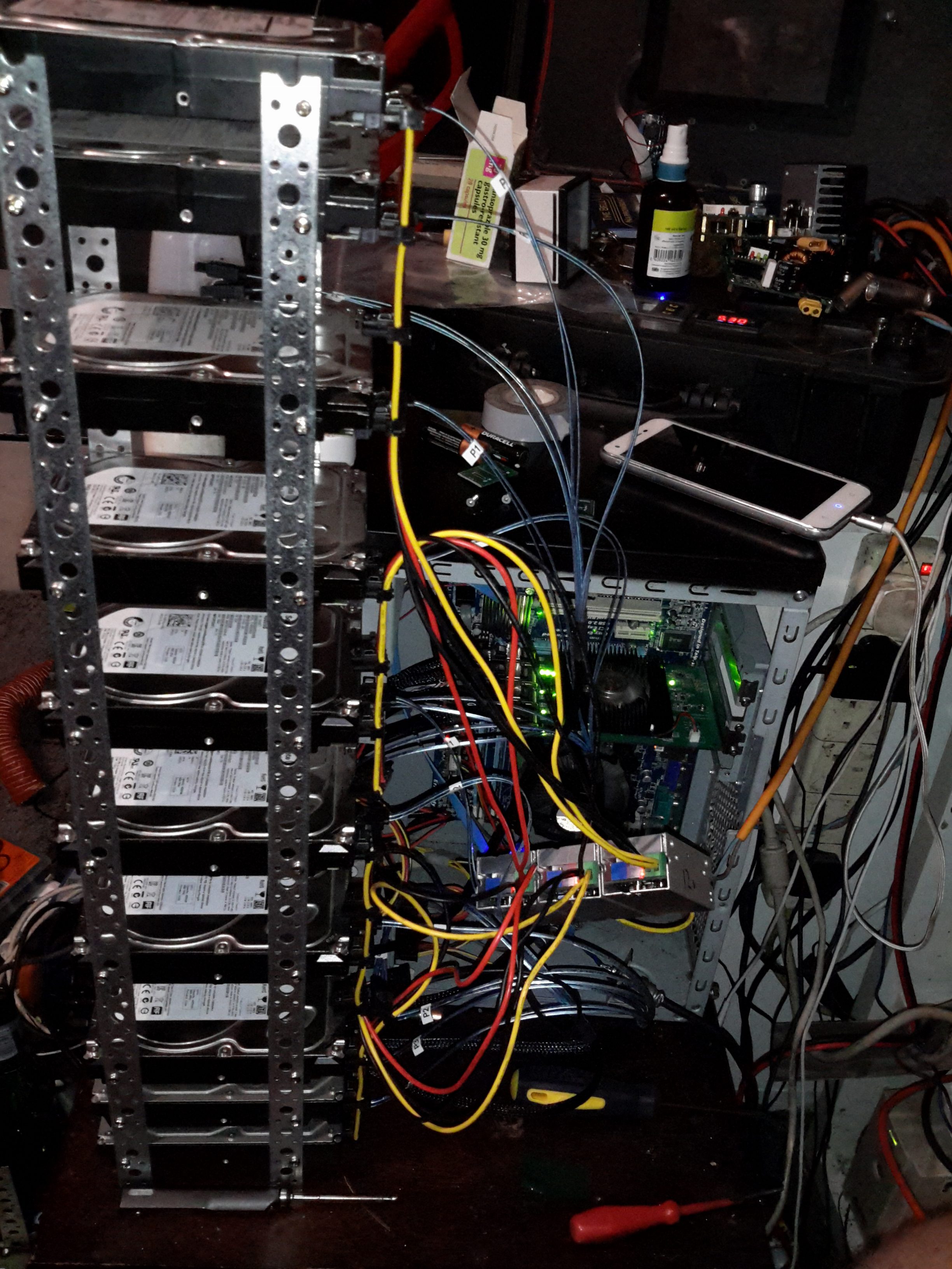
Disk Array
Since I don’t have a suitable case with built in drive bays, (again, they’re expensive), I’ve had to improvise with some steel strip to hold the disks in a stack. 3 DC-DC converters provides the regulated 12v & 5v for the disks from the main unregulated 12v system supply. Both the host system & the disks run from my central battery-backed 12v system, which acts like a large UPS for this.
The SATA power splitters were custom made, the connectors are Molex 67926-0001 IDC SATA power connectors, with 18AWG cable to provide the power to 4 disks in a string.
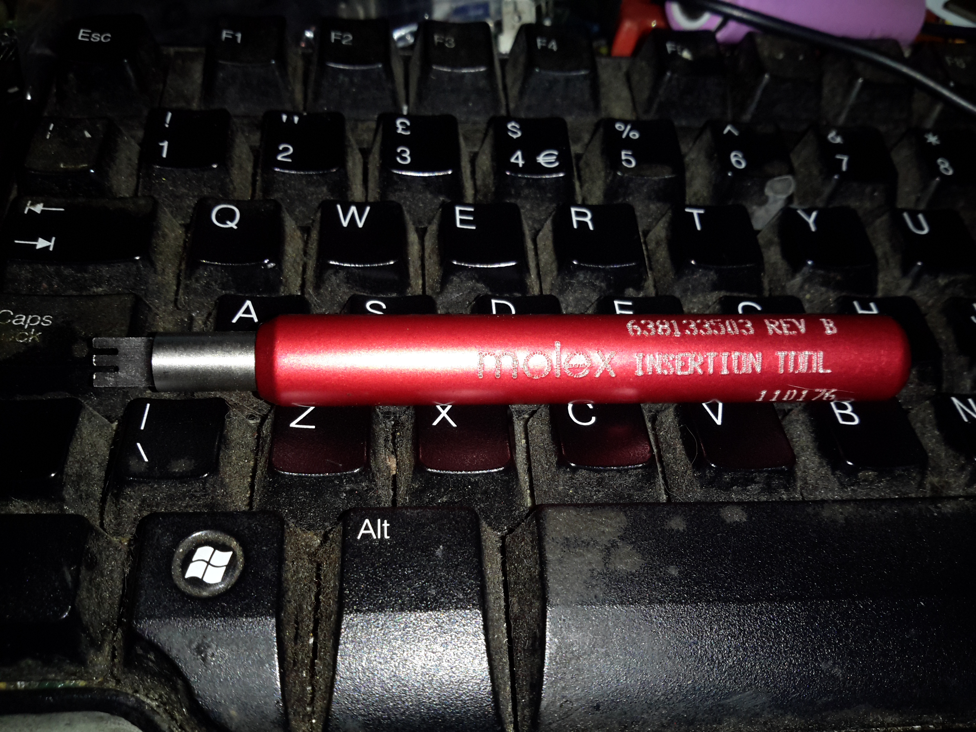
IDT Insertion Tool
These require the use of a special tool if you value your sanity, which is a bit on the expensive side at £25+VAT, but doing it without is very difficult. You get a very well made tool for the price though, the handle is anodised aluminium & the tool head itself is a 300 series stainless steel.
For accurate measurements, you’ll need an optical instrument such as a monochromator or spectrophotometer or optical spectrum analyzer. But to simply see the complexity of the discharge spectrum inside the bore of a He-Ne laser tube, it’s much easier and cheaper.
(Spectra for various elements and compounds can be easily found by searching the Web. The NIST Atomic Spectra Database has an applet which will generate a table or plot of more spectral lines than you could ever want.)
Instant Spectroscope for Viewing Lines in He-Ne Discharge
It is easy to look at the major visible lines. All it takes is a diffraction grating or prism. I made my instant spectroscope from the diffraction grating out of some sort of special effects glasses – found in a box of cereal, no less! – and a monocular (actually 1/2 of a pair of binoculars).
If you missed the Kellogg’s option, diffraction gratings can be purchased from places like Edmund Scientific. You don’t need anything fancy – any of the inexpensive ‘transmission replica gratings’ on a flat rigid substrate or mounted between a pair of plane glass plates will be fine. In a pinch, a CD disc or other optical media will work but only as a reflection grating so mounting may be a problem. A spectroscope can also be made with a prism of course but a diffraction grating is likely to be less expensive and better for this application since it is much lighter and easier to mount.
The plasma tube of a bare He-Ne laser is an ideal light source since it provides its own slit as the glow discharge is confined to the long narrow capillary bore. However, this approach can also be used with other lasers as long as the beam can be focused to a spot on a wall or screen. This will produce a ‘bright spot spectra’ instead of politically correct lines but you can’t have everything. 🙂
The diffraction grating can be used by itself but the additional optics will provide magnification and other benefits for people with less than perfect eyeballs.
Glue the diffraction grating to a cardboard sleeve that can be slipped over the (or one) objective of a monocular, binocular, or small telescope – or the telephoto lens of your camera. Orient it so that the dispersion will be vertical (since your slit will be horizontal).
Operate the HeNe tube on a piece of black velvet or paper. This will result in optimum contrast. This is best done in a darkened room where the only source of light is the laser tube itself. Just don’t trip and zap yourself on the high voltage!
A diffraction grating produces several images. The zero’th order will be the original image seen straight ahead. The important ones are the first order spectra. Tip the instrument up or down to see these. The dispersion direction – order of the colours – will depend on which way it is tipped.
Any distance beyond the closest focus of your instrument will work but being further away will reduce the effective width of the ‘slit’ resulting in the ability to distinguish more closely spaced lines.
The shear number of individual spectral lines present in the discharge is quite amazing. You will see the major red, orange, yellow, and green lines as well as some far into the blue and violet portions of the spectrum and toward the IR as well.
Bright Line Spectra of Helium and Neon
All of those shown will be present as well as many others not produced by the individual gas discharges. There are numerous IR lines as well but, of course, these will not be visible.
Place a white card in the exit beam and note where the single red output line of the He-Ne tube falls relative to the position and intensity of the numerous red lines present in the gas discharge.
As an aside, you may also note a weak blue/green haze surrounding the intense main red beam (not even with the spectroscope). This is due to the blue/green (incoherent) spectral lines in the discharge being able to pass through the output mirror which has been optimized to reflect well (>99 percent) at 632.8 nm and is relatively transparent at wavelengths some distance away from these (shorter and longer but you would need an IR sensor to see the longer ones). Since it is not part of the lasing process, this light diverges rapidly and is therefore only visible close to the tube’s output mirror.
Dynamic Measurement of Discharge Spectra
The following is trivial to do if you have a recording spectrometer and external mirror He-Ne laser. For an internal mirror He-Ne laser tube, it should be possible to rock one of the mirrors far enough to kill lasing without permanently changing alignment. If you don’t have proper measuring instruments, don’t worry, this is probably in the “Gee wiz, that’s neat but of marginal practical use” department. 🙂
(From: George Werner (glwerner@sprynet.com).)
Here is an effect I found many years ago and I don’t know if anyone has pursued it further.
We had a recording spectrometer in our lab which we used to examine the incoherent light coming from the laser discharge. This spectrum when lasing was slightly different from the spectrum when not lasing, which one can expect since energy levels are redistributed. As with most detectors, ours used a chopper in the spectrometer light beam and a lock-in amplifier.
Instead of putting the chopper in the path of light going to the spectrometer, I put it in the path of the internal laser beam, so that instead of an open/closed signal going to the amplifier it was a lasing/not-lasing signal. What was recorded then was three kinds of spectrum lines: some deflected positive in the normal way, others deflected negative, and the third group were those that were unaffected by chopping, in which case when we passed over the line we only saw an increase in the noise level. Setting up such a test is easy. The hard part is interpreting the data in a meaningful way.
Other Colour Lines in Red He-Ne Laser Output
When viewing spectral lines in the actual beam of a red He-Ne laser, you may notice some very faint ones far removed from the dominant 632.8 nm line we all know and love. (This, of course, also applies to other colour He-Ne lasers.)
For He-Ne lasers, the primary line (usually 632.8 nm) is extremely narrow and effectively a singularity given any instrumentation you are likely to have at your disposal. Any other lines you detect in the output are almost certainly from two possible sources but neither is actual laser emission:
Plasma discharge – there are many strong emission lines in the actual discharge – and none of them are actually at the 632.8nm lasing wavelength! These extend from the mid-IR through the violet.Close to the output mirror, you may see some of this light seeping through especially at wavelengths in the green, blue, and violet, for which the dielectric mirrors are nearly perfectly transparent. However, such light will be quite divergent and diffuse and won’t be visible at all more than a couple of inches from the mirror.
Superradiance – As we know, He-Ne lasers can be made to operate at a variety of wavelengths other than the common 632.8nm red. The physics for these is still applicable in a red He-Ne tube but the mirrors do not have the needed reflectivity at these other wavelengths and therefore the resonator gain is too low to support true laser action. However, stimulated emission can still take place in superradiance mode – one pass down the tube and out, exiting easily for the green wavelength in particular since the dielectric mirrors are quite transparent in that region of the spectrum.The result will be a weak green beam that can sometimes be observed with a spectroscope in a very dark room room. It isn’t really quite as coherent or monochromatic as the beam from a true green He-Ne laser and probably has much wider divergence but nonetheless may be present. It may be easier to see this by using your spectroscope to view the bright spot from the laser on a white card rather than by deflecting the beam and trying to locate the green dot off to one side.Note: I have not been able to detect this effect on the short He-Ne tubes I have checked.
Since the brightness of the discharge and superradiance output should be about the same from either mirror, using the non-output end (high reflector) should prove easier (assuming it isn’t painted over or otherwise covered) since the red beam exiting from this mirror will be much less intense and won’t obscure the weak green beam.
Note that argon and krypton ion lasers are often designed for multiline output where all colours are coherent and within an order of magnitude of being equal to each other in intensity or with a knob to select an individual wavelength. Anything like this is only rarely done with He-Ne lasers because it is very difficult (and expensive) due to the low gain of the non-red lines.
I recently dug out my other card printer to fit it with a 12v regulator, (it’s 24v at the moment), and figured I’d do a teardown post while I had the thing in bits.
This is a less industrial unit than my Zebra P330i, but unlike the Zebra, it has automatic duplexing, it doesn’t have Ethernet connectivity though.
Unlike domestic printers, which are built down to a price, these machines are very much built up to a spec, and feature some very high quality components.
Naked Printer
Here’s the mechanism with the cowling removed. This is the main drive side of the printer, with the main drive stepper at left, ribbon take-up spool motor lower right, and the duplex module stepper motors at far right.
Main Motor Drive
The main drive motor runs the various rollers in the card path through a pair of synchronous belts, shown here.
Main Stepper
The stepper itself is a quality ball-bearing Sanyo Denki bipolar motor.
Main Stepper Driver
Electrical drive is provided to the stepper with a L6258EX DMOS universal motor driver. This chip can also drive DC motors as well as steppers.
Ribbon Supply Spool
Here is the encoder geared onto the ribbon supply spool. This is used to monitor the speed the ribbon is moving relative to the card.
Printer Top
Here’s a top view through the printer, the blue roller on the left cleans the card as it’s pulled from the feeder, the gold coloured spool to it’s right is the ribbon supply reel. The cooling fan on the right serves to stop the print head overheating during heavy use.
Spool Take Up Motor
The spool take-up reel is powered by another very high quality motor, a Buhler DC gearmotor. These printers are very heavily over engineered!
This motor drives the spool through an O-Ring belt, before the gear above. This allows the drive to slip in the event the ribbon jams, preventing it from breaking.
Duplex Unit Stepper Drivers
The pair of steppers that operate the duplexing unit are driven by a separate board, with a pair of L6219DS bipolar stepper driver ICs. There are also a couple of opto-sensors on this board for the output hopper.
Main Control PCB
All the mechanisms of the printer are controlled from this main PCB, which handles all logic & power supply functions. Sections on the board are unpopulated, these would be for the Ethernet interface, smart card programming & magstripe programming.
Main CPU
The brains of the operation is this ColdFire MCF5208CVM166 32-bit microprocessor. It features 16KB of RAM, 8KB of cache, DMA controller, 3 UARTs, SPI, 10/100M Ethernet and low power management. This is a fairly powerful processor, running at 166MHz.
It’s paired with an external 128Mbit SDRAM from Samsung, and a Spansion 8Mbit boot sector flash, for firmware storage.
USB Interface & Power Input
Here the USB interface IC is located. It’s a USBN9604 from Texas Instruments, this interfaces with the main CPU via serial.
This is a late 90’s business timeclock, used for maintaining records of staff working times, by printing the time when used on a sheet of card.
Front Internal
Here is the top cover removed, which is normally locked in place to stop tampering. The unit is programmed with the 3 buttons & the row of DIP switches along the top edge.
Instructions
Closeup of the settings panel, with all the various DIP switch options.
CPU & Display
Cover plate removed from the top, showing the LCD & CPU board, the backup battery normally fits behind this. The CPU is a 4-bit microcontroller from NEC, with built in LCD driver.
PSU & Drivers
Power Supply & prinhead drivers. This board is fitted with several NPN Darlington transistor arrays for driving the dox matrix printhead.
Printhead
Printhead assembly itself. The print ribbon fits over the top of the head & over the pins at the bottom. The drive hammers & solenoids are housed in the circular top of the unit.
Printhead Bottom
Bottom of the print head showing the row of impact pins used to create the printout.
Bottom of the solenoid assembly with the ribbon cable for power. There are 9 solenoids, to operate the 9 pins in the head.
Return Spring
Top layer of the printhead assembly, showing the leaf spring used to hold the hammers in the correct positions.
Hammers
Hammer assembly. The fingers on the ends of the arms push on the pins to strike through the ribbon onto the card.
Solenoids
The ring of solenoids at the centre of the assembly. These are driven with 3A darlington power arrays on the PSU board.
Gearbox Internals
There is only a single drive motor in the entire unit, that both clamps the card for printing & moves the printhead laterally across the card. Through a rack & pinion this also advances the ribbon with each print.
This is the teardown of a Zebra P330i plastic card printer, used for creating ID cards, membership cards, employee cards, etc. I got this as a faulty unit, which I will detail later on.
This printer supports printing on plastic cards from 1-30mils thick, using dye sublimation & thermal transfer type printing methods. Interfaces supplied are USB & Ethernet. The unit also has the capability to be fitted with a mag stripe encoder & a smart card encoder, for extra cost.
Print Engine
On the left here is the print engine open, the blue cartridge on the right is a cleaning unit, using an adhesive roller to remove any dirt from the incoming card stock.
This is extremely important on a dye sublimation based printing engine as any dirt on the cards will cause printing problems.
Cards In Feeder
Here on the right is the card feeder unit, stocked with cards. This can take up to 100 cards from the factory.
The blue lever on the left is used to set the card thickness being used, to prevent misfeeds. There is a rubber gate in the intake port of the printer which is moved by this lever to stop any more than a single card from being fed into the print engine at any one time.
Card Feeder Belt
Here is the empty card feeder, showing the rubber conveyor belt. This unit was in fact the problem with the printer, the drive belt from the DC motor under this unit was stripped, preventing the cards from feeding into the printer.
Print Head
Here is a closeup of the print head assembly. The brown/black stripe along the edge is the row of thin-film heating elements. This is a 300DPI head.
Print Station
This is under the print head, the black roller on the left is the platen roller, which supports the card during printing. The spool in the center of the picture is the supply spool for the dye ribbon.
In the front of the black bar in the bottom center, is a two-colour sensor, used to locate the ribbon at the start of the Yellow panel to begin printing.
LCD PCB
Inside the top cover is the indicator LCD, the back of which is pictured right.
This is a 16×1 character LCD from Hantronix. This unit has a parallel interface.
LCD
Front of the LCD, this is white characters on a blue background.
Roller Drive Belts
Here is the cover removed from the printer, showing the drive belts powering the drive rollers. There is an identical arrangement on the other side of the print engine running the other rollers at the input side of the engine.
Mains Filter
Here the back panel has been removed from the entire print engine, complete with the mains input wiring & RFI filtering.
This unit has excellent build quality, just what is to be expected from a £1,200+ piece of industrial equipment.
Main Frame With Motors
The bottom of the print engine, with all the main wiring & PCB removed, showing the main drive motors. The left hand geared motor operates the head lift, the centre motor is a stepper, which operates the main transmission for the cards. The right motor drives the ribbon take up spindle through an O-Ring belt.
Feeder Drive Motor
Card feeder drive motor, this connects to the belt assembly through a timing belt identical to the roller drive system.
All these DC geared motors are 18v DC, of varying torque ratings.
Power Supply
Here is the main power supply, a universal input switch-mode unit, outputting 24v DC at 3.3A.
PSU Label
PSU info. This is obviously an off the shelf unit, manufactured by Hitek. Model number FUEA240.
Print Engine Rear
The PSU has been removed from the back of the print engine, here is shown the remaining mechanical systems of the printer.
Print Engine Components
A further closeup of the print engine mechanical bay, the main stepper motor is bottom centre, driving the brass flywheel through another timing belt drive. The O-Ring drive on the right is for the ribbon take up reel, with the final motor driving the plastic cam on the left to raise/lower the print head assembly.
The brass disc at the top is connected through a friction clutch to the ribbon supply reel, which provides tension to keep it taut. The slots in the disc are to sense the speed of the ribbon during printing, which allows the printer to tell if there is no ribbon present or if it has broken.
RFID PCB
Here is a further closeup, showing the RFID PCB behind the main transmission. This allows the printer to identify the ribbon fitted as a colour or monochrome.
The antenna is under the brass interrupter disc on the left.
I/O Daughterboard
The I/O daughterboard connects to the main CPU board & interfaces all the motors & sensors in the printer.
Main PCB
Here is the main CPU board, which contains all the logic & processing power in the printer.
CPU
Main CPU. This is a Freescale Semiconductor part, model number MCF5206FT33A, a ColdFire based 32-bit CPU. Also the system ROM & RAM can be seen on the right hand side of this picture.
Ethernet Interface
Bottom of the Ethernet interface card, this clearly has it’s own RAM, ROM & FPGA. This is due to this component being a full Parallel interface print server.
Ethernet Interface Top
Top of the PCB, showing the main processor of the print server. This has a ferrite sheet glued to the top, for interference protection.
This is the Velleman MK179 Proximity Card Reader, which is supplied in kit form. In the image above you can see the completed kit, the read coil is etched onto the black PCB on the left. Bringing a recognised card close to the coil operates the relay on the main PCB for a programmable amount of time.
Main PCB
Closeup of the main PCB, 12v DC input at top right. Left IC is an LM358 dual Op-Amp, the IC on the right is a PIC12F629 with Velleman’s custom firmware.
Logic power is supplied to the ICs & the oscillator from the LM7805 regulator at the top of the PCB. The relay is a standard 15A SPDT 12v coil relay, with the switch contacts broken out onto the screw terminals on the left.
Schematic Diagram
As it is not provided with the kit, unlike other Velleman kits, here is the schematic for this.
This unit was bought from eBay to experiment with Magnetic Stripe cards, for little money. This unit is capable of reading & writing all 3 tracks, & both Hi-Co & Lo-Co card types.
Interfaced to a PC through USB, this has a built in PL2303 USB-Serial IC & requires 3A at 9v DC to operate.
The 3 Indicator LEDs on the top of the unit can be toggled by the included software for Power/OK/Fault condition signalling.
Unit Bottom
Bottom of the unit with the model labels.
Model Label
Closeup of the model label & serial number.
PCB Bottom
Here the bottom cover has been removed, showing the main PCB. The pair of large ICs bottom center interface with the magnetic heads. The IC above them has had the markings sanded off.
USB-Serial Interface
Closeup of the Prolific PL-2303 USB-Serial converter IC.
PCB Top
Here the connections to the R/W heads are visible, current limiting resistors at the left for the write head, a pair of signal relays, a pair of optoisolators & a LM7805 linear voltage regulator.
LEDs
Here is the trio of indicator LEDs on a small sub-board.
Frame Bottom
The PCB has been removed from the main frame here, the only component visible is the rotary encoder.
Rotary Encoder
The rotary encoder has a rubber wheel fitted, which reads the speed of the card as it is being swiped for writing. This allows the control logic to write the data to the stripe at the correct rate for the speed of the card. This allows the unit to write cards from 5-50 inches per second speed.
The Write head is directly behind the rubber pressure roller.
Read/Write Heads
Here you can see the R/W head assembly. The write head is on the right, read on the left. When a card is written to, it immediately gets read by the second head for verification.
Here is a cheap USB 8-in-1 card reader. Power & Access LEDs are on top left.
PCB Top
Top of the PCB. The OTi IC is the interface IC to the USB port, part number is OTI002126. Card sockets on the top here are CF/Microdrive & Memory Stick.
Here is an old Belkin Wireless G network card. This is a PCMCIA version.
Bottom Label
Here is the bottom of the device, with all the details.
Antenna
Plastic antenna cover removed, showing the pair of 2.4GHz etched antennae. There is a pair of LEDs on the upper left of the PCB showing activity & link status.
PCB
Overall view of the PCB, antennae on the left, RF chipset in centre, WiFi controller IC on right, and PCMCIA socket on far right. Can below wireless controller is a quartz crystal for the clock.
Chipset
Closeup of the chipset, a Ralink RT2560F wireless controller on the right & a RT2525L transceiver on the left.
This is a little security measure you get with Internet Banking with the Co-Op, generates codes to confirm your identity using your bank card. About the size of a pocket calculator, this is the keypad & screen.
Card Slot
The rear of the unit, the card slots into the top, manufactured by Gemalto Digital Security.
Card Contacts
Outer back cover removed, showing the 8 contacts for the chip on the bank card, the 2 contacts below that switch on power when a card is inserted. Power comes from 2 lithium coin cells in the compartment on the lower left.
PCB Rear
PCB removed from the casing, showing the internal components. Two large pads at top left are battery connections, while the only IC on the board is the main CPU, under the card connector. 6MHz oscillator & 32Khz crystal on board for processing & timekeeping. LCD screen connection at far right.
Keypad Contacts
Reverse side of the PCB, with the keypad contacts. LCD on right, with programming interface pads at side of keypad.
Here is a more modern phone, the Motorola V360v. Features include Dual screens, 640×480 VGA camera, full col
our TFT Main LCD, SD-Micro slot.
Here on the back the grey scale LCD can be seen, with the camera lens to the right of the Motorola logo
Keypad
Here the phone is opened showing the keypad & the full colour TFT LCD display.
Battery Compartment
Here the battery is removed from the unit, showing the SIM connector. The antenna cover is still on at the bottom.
Antenna
The antenna cover has been removed in this shot, the antenna is the white section at the bottom, With the loudspeaker & the external antenna connector hidden at the right.
PCB
Here is the main PCB. Parts from left are the Bluetooth module at the top, supplied by Broadcom, the SD Card socket at the bottom. Main CPU next to that is the Freescale SC29343VKP. Above right of the CPU is the Freescale SC13890P23A Charger, Power & Audio IC. Below is the SIM card socket. Under the main CPU is the Intel Flash memory IC. ICs inside the shields are the RF sections for transmit & receive.
Cover Removed
Rear of the display unit showing the monochrome LCD. The camera module on the bottom left. Ear speaker on the far right of the unit.
Main LCD
Main colour TFT LCD.
Camera
Camera module removed from the LCD unit.
Vibra-Motor
The vibration motor attached to one of the LCD looms.
This is a HP PhotoSmart 375 portable photo printer. With built in card reader, screen & PictBridge.
Top of the printer showing the UI Buttons & Screen.
Front
Front of the unit, card reader slots at the top, Pictbridge USB connector at top left. Paper out slot at bottom. Cartridge door is on the right.
Cartridge Door
Here the cartridge door is open. Takes HP 95 Tri-Colour Inkjet Cartridge.
Battery Compartment
Battery compartment on the bottom of the unit. A Li-Ion battery pack can be installed here for mobile photo printing.
Bottom Label
Specifications label.
USB + Power
Power adaptor & USB connection for PC use.
Paper Tray
Rear door opened. Showing the paper feed tray.
Paper Feeder
Rear door has been removed in this shot. Paper feed roller & platen roller can be seen here.
Rear Cover Paper Feeder
Paper holder attached to rear door.
Top Cover
Bottom of the top cover, with connections for the buttons & LCD panel.
Main PCB
This is the main PCB of the unit. Controls all aspects of the printer. CPU in center, card reader sockets are along bottom edge. various support circuitry surrounds the CPU.
Rear
Rear shell has been removed here. Showing the main frame & the carriage drive motor on the left.
Carriage Drive
Closeup of the carriage drive motor & timing belt system. All the motors in this printer are DC servo motors, not steppers.
Main Drive Motor
Main drive motor, feeds paper, drives rollers, operates cleaning mechanism for the inkjets.
Shaft Encoder
Mainshaft encoder. Main drive motor is bottom right hand side with timing belt drive.
CPU
Closeup of the CPU. This is a Phillips ARM chip, unknown spec.
Card Reader Sockets
Detail of the card reader sockets, this unit takes all current types of Flash memory card.
HP 95 Tri-color Inkjet Print Cartridge
Tip Jar
If you’ve found my content useful, please consider leaving a donation by clicking the Tip Jar below!
All collected funds go towards new content & the costs of keeping the server online.