I have found myself needing some more in the way of High Voltage supplies of late, with the acquisition of the new He-Ne laser tubes, so I went trawling eBay for something that would be suitable to run these tubes. (I currently only have a single He-Ne laser PSU brick, and they’re notoriously hard to find & rather expensive).
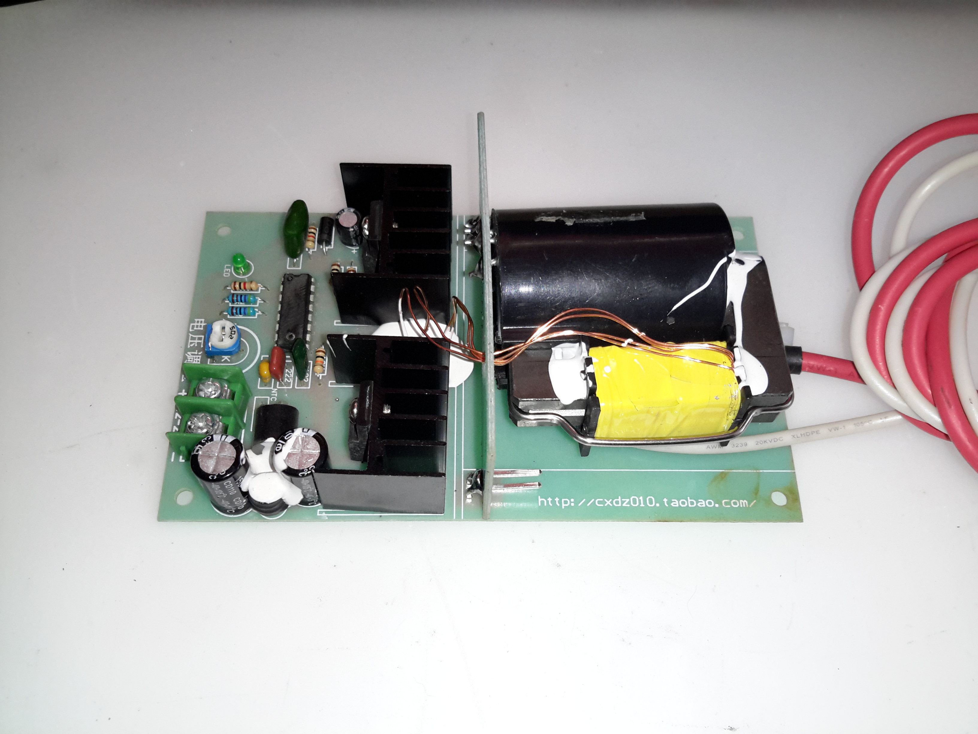
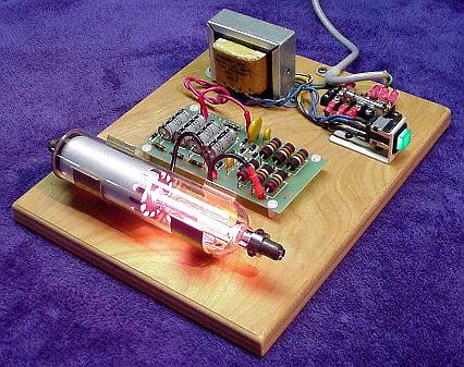
This supply is rated at 1kV-10kV output, at 35W power level. Unfortunately this supply isn’t capable of sustaining the discharge in a large He-Ne tube, the impedance of the supply is far too high. Still, it’s useful for other experiments.
The flyback-type transformer clearly isn’t a surplus device from CRT manufacture, as there are very few pins on the bottom, and none of them connect to the primary side. The primary is separately wound on the open leg of the ferrite core.
Drive Electronics
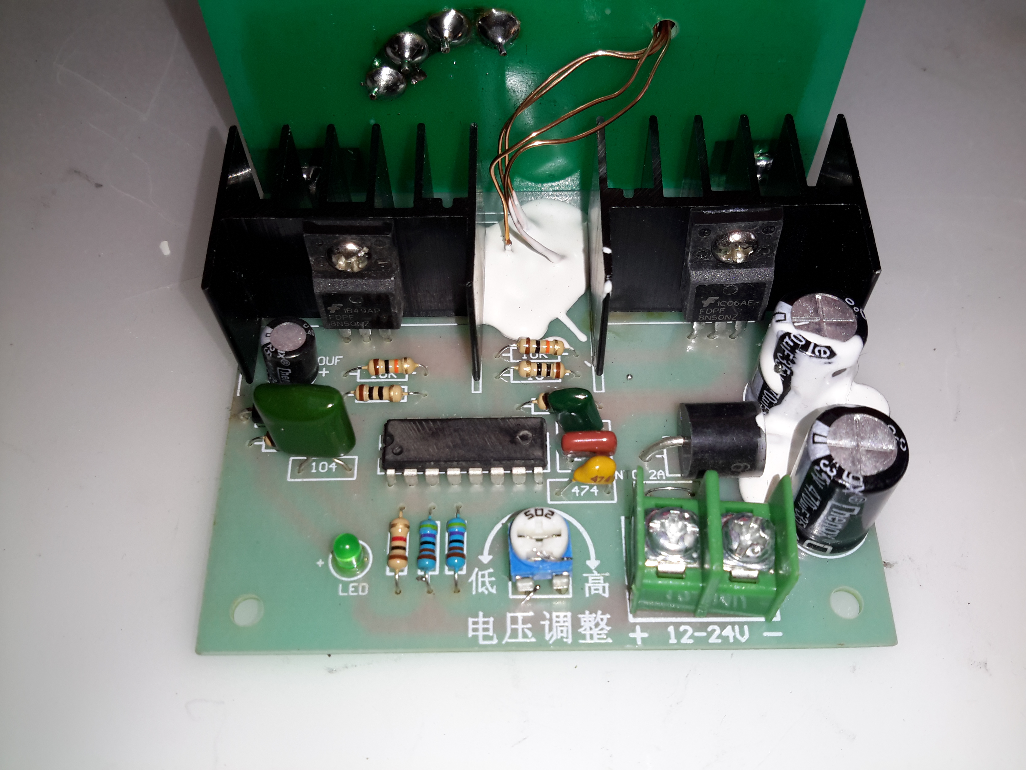
The drive electronics are pretty simple, there’s a controller IC (with the number scrubbed off – guessing it’s either a 556 dual timer or a SMPS controller), a pair of FDP8N50NZ MOSFETs driving the centre-tapped primary winding.
The drive MOSFETs aren’t anything special in this case: they’re rated at 500v 8A, 850mΩ on resistance. This high resistance does make them get rather hot even with no load on the output, so for high power use forced-air cooling from a fan would definitely be required.
Test Setup
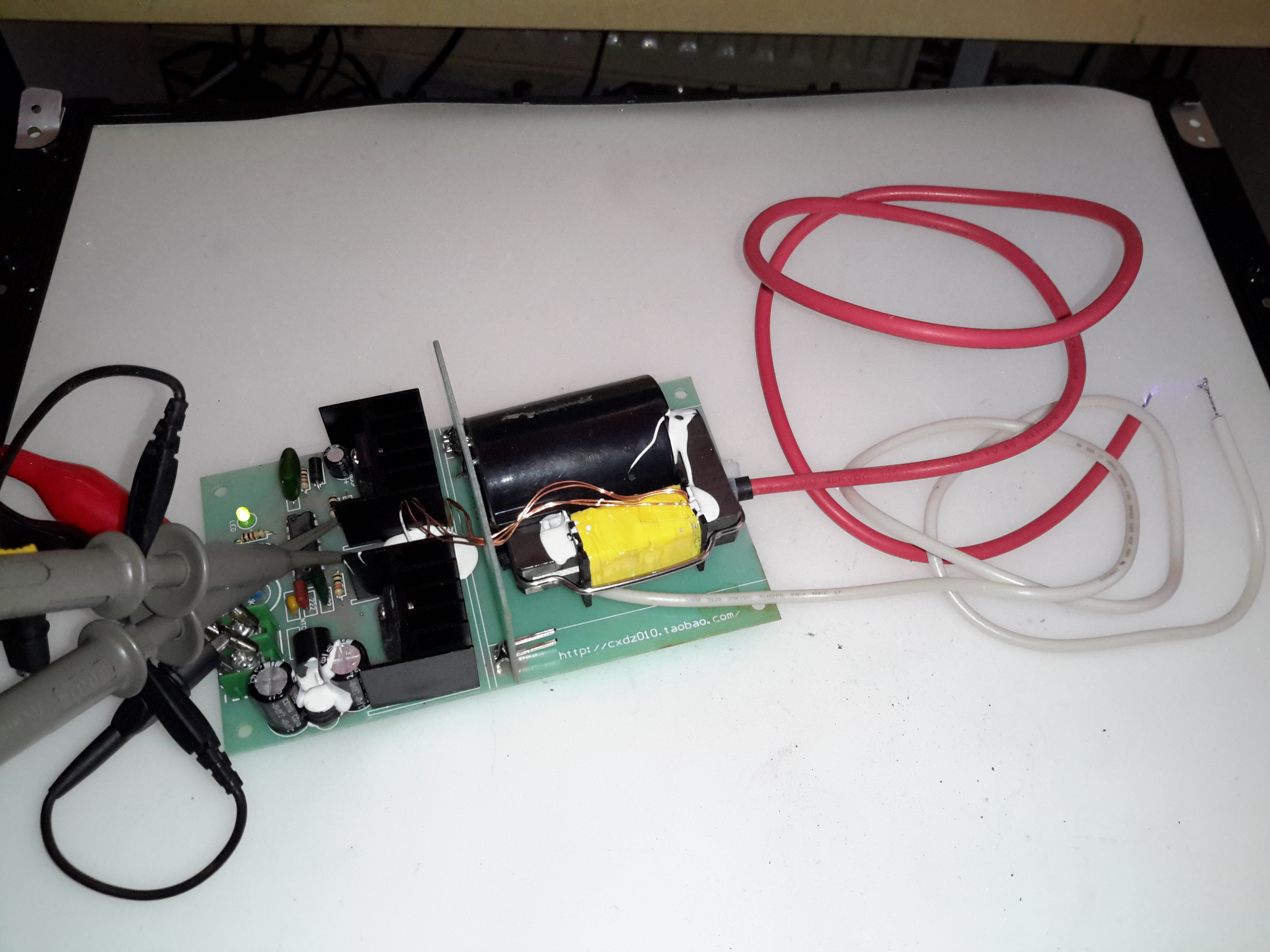
Here’s the supply on test, I’ve got the scope probes connected to the gate resistors of the drive MOSFETs.
Waveforms
On the scope the primary switching waveforms can be seen. The FETs operate in push-pull mode, there’s a bit of a ring on the waveform, but they’re pretty nice square waves otherwise.
Arc
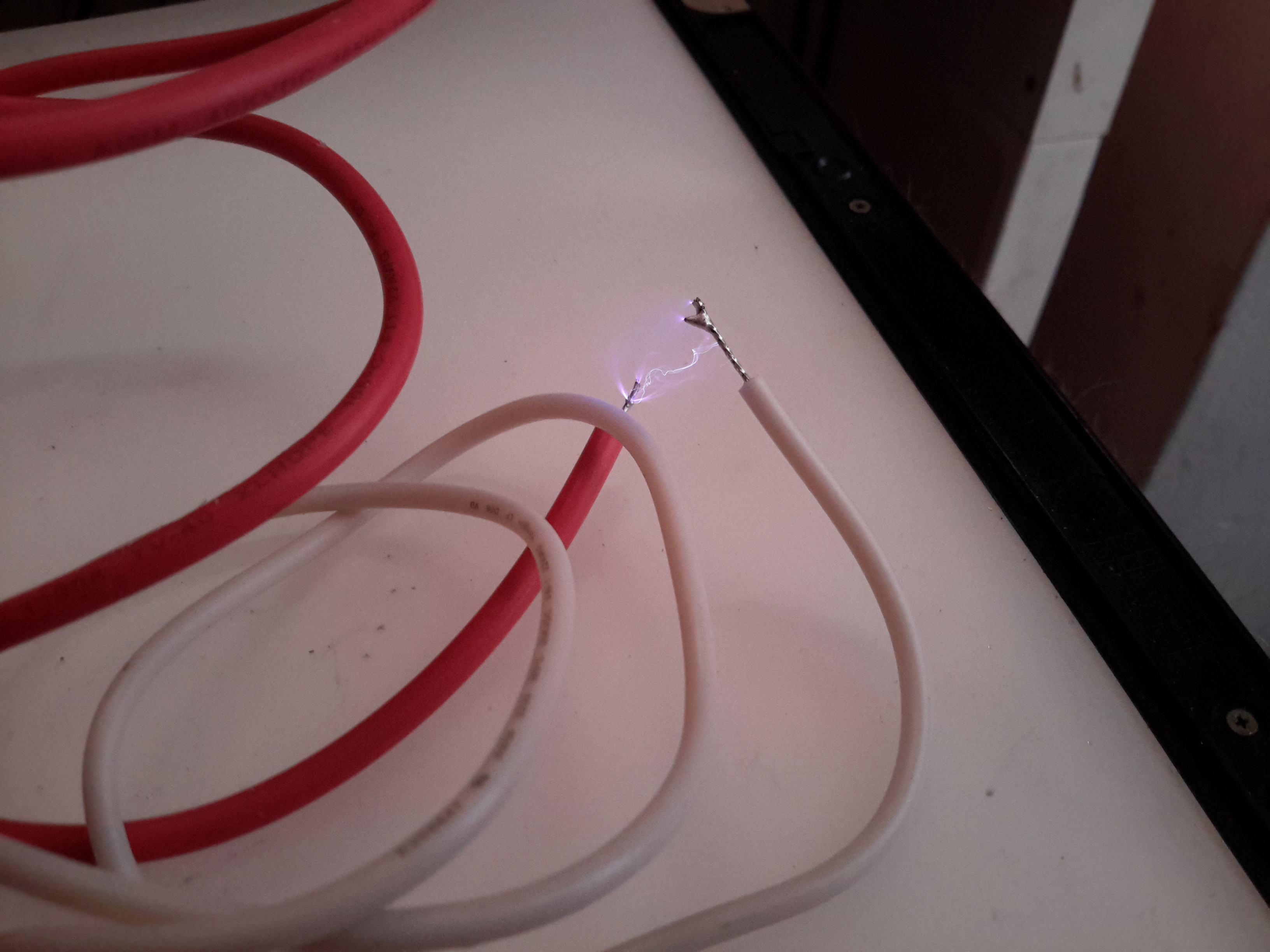
At maximum power on 12v input, about 25mm of gap is possible with an arc.
Power for a He-Ne laser is provided by a special high voltage power supply and consists of two parts (these maximum values depend on tube size – a typical 1 to 10 mW tube is assumed):
Operating voltage of 1,000 to 3,000v DC at 3 to 8mA.Like most low current discharge tubes, the He-Ne laser is a negative resistance device. As the current *increases* through the tube, the voltage across the tube *decreases*. The incremental magnitude of the negative resistance also increases with decreasing current.
Starting voltage of 5 to 12 kV at almost no current.In the case of a He-Ne tube, the initial breakdown voltage is much greater than the sustaining voltage. The starting voltage may be provided by a separate circuit or be part of the main supply.Often, you may find a wire or conductive strip running from the anode or ballast resistor down to a loop around the tube in the vicinity of the cathode. (Or there may be a recommendation for this in a tube spec sheet.) This external wire loop is supposed to aid in starting (probably where a pulse type starter is involved). There may even be some statistical evidence suggesting a reduction in starting times. I wouldn’t expect there to be much, if any, benefit when using a modern power supply but it might help in marginal cases. But, running the high voltage along the body of the tube requires additional insulation and provides more opportunity for bad things to happen (like short circuits) and may represent an additional electric shock hazard. And, since the strip has some capacitance, operating stability may be impaired. I would probably just leave well enough alone if a starting strip is present and the laser operates without problems but wouldn’t install one when constructing a laser head from components.
With every laser I’ve seen using one of these strips, it has either had virtually or totally no effect on starting OR has caused problems with leakage to the grounded cylinder after awhile. Cutting away the strip in the vicinity of the anode has cured erratic starting problems in the latter case and never resulted in a detectable increase in starting time.
With a constant voltage power supply, a series ballast resistor is essential to limit tube current to the proper value. A ballast resistor will still be required with a constant current or current limited supply to stabilize operation. The ballast resistor may be included as part of a laser head but will be external for most bare tubes. (The exceptions are larger Spectra-Physics He-Ne lasers where the ballast resistors are also inside a glass tube extension, electrically connected but sealed off from the main tube.In order for the discharge to be stable, the total of the effective power supply resistance, ballast resistance, and tube (negative) resistance must be greater than 0 ohms at the operating point. If this is not the case, the result will be a relaxation oscillator – a flashing or cycling laser!
Power supply polarity is important for He-Ne tubes. Electrical behaviour may be quite different if powered with incorrect polarity and tube damage (and very short life) will likely be the result from prolonged operation.
The positive output of the power supply is connected to a series ballast resistor and then to the anode (small) electrode of the He-Ne tube. This electrode may actually be part of the mirror assembly at that end of the tube or totally separate from it. The distance from the resistors to the electrode should be minimized – no more than 2 or 3 inches.
The negative output of the power supply is connected to the cathode (large can) electrode of the He-Ne tube. This electrode may be electrically connected to the mirror mount at that end of the tube but is a separate aluminium cylinder that extends for several inches down the tube. CAUTION: Some He-Ne tubes use a separate terminal for the cathode and sometimes the anode as well, not the mirror mount(s). Powering one of these via the mirror mounts may result in lasing but will also result in tube damage.
Note: He-Ne tube starting voltage is lower and operating voltage is higher when powered with reverse polarity. With some power supply designs, the tube may appear to work equally well or even better (since starting the discharge is easier) when hooked up incorrectly. However, this is damaging to the anode electrode of the tube (and may result in more stress on the power supply as well due to the higher operating voltage) and must be avoided (except possibly for a very short duration during testing).
Every He-Ne tube will have a nominal current rating. In addition to excessive heating and damage to the electrodes, current beyond this value does not increase laser beam intensity. In fact, optical output actually decreases (probably because too high a percentage of the helium/neon atoms are in the excited state). You can easily and safely demonstrate this behaviour if your power supply has a current adjustment or you run an unregulated supply using a Variac. While the brightness of the discharge inside the tube will increase with increasing current, the actual intensity of the laser beam will max out and then eventually decrease with increasing current. (This is also an easy way of determining optimal tube current if you have not data on the tube – adjust the ballast resistor or power supply for maximum optical output and set it so that the current is at the lower end of the range over which the beam intensity is approximately constant.) Optical noise in the output will also increase with excessive current.
The efficiency of the typical He-Ne laser is pretty pathetic. For example, a 2 mW HeNe tube powered by 1,400 V at 6mA has an efficiency of less than 0.025%. More than 99.975% of the power is wasted in the form of heat and incoherent light (from the discharge)! This doesn’t even include the losses of the power supply and ballast resistor.
A few He-Ne lasers – usually larger or research types – have used a radio frequency (RF) generator – essentially a radio transmitter to excite the discharge. This was the case with the original He-Ne laser but is quite rare today given the design of internal mirror He-Ne tubes and the relative simplicity of the required DC power supply.
For accurate measurements, you’ll need an optical instrument such as a monochromator or spectrophotometer or optical spectrum analyzer. But to simply see the complexity of the discharge spectrum inside the bore of a He-Ne laser tube, it’s much easier and cheaper.
(Spectra for various elements and compounds can be easily found by searching the Web. The NIST Atomic Spectra Database has an applet which will generate a table or plot of more spectral lines than you could ever want.)
Instant Spectroscope for Viewing Lines in He-Ne Discharge
It is easy to look at the major visible lines. All it takes is a diffraction grating or prism. I made my instant spectroscope from the diffraction grating out of some sort of special effects glasses – found in a box of cereal, no less! – and a monocular (actually 1/2 of a pair of binoculars).
If you missed the Kellogg’s option, diffraction gratings can be purchased from places like Edmund Scientific. You don’t need anything fancy – any of the inexpensive ‘transmission replica gratings’ on a flat rigid substrate or mounted between a pair of plane glass plates will be fine. In a pinch, a CD disc or other optical media will work but only as a reflection grating so mounting may be a problem. A spectroscope can also be made with a prism of course but a diffraction grating is likely to be less expensive and better for this application since it is much lighter and easier to mount.
The plasma tube of a bare He-Ne laser is an ideal light source since it provides its own slit as the glow discharge is confined to the long narrow capillary bore. However, this approach can also be used with other lasers as long as the beam can be focused to a spot on a wall or screen. This will produce a ‘bright spot spectra’ instead of politically correct lines but you can’t have everything. 🙂
The diffraction grating can be used by itself but the additional optics will provide magnification and other benefits for people with less than perfect eyeballs.
Glue the diffraction grating to a cardboard sleeve that can be slipped over the (or one) objective of a monocular, binocular, or small telescope – or the telephoto lens of your camera. Orient it so that the dispersion will be vertical (since your slit will be horizontal).
Operate the HeNe tube on a piece of black velvet or paper. This will result in optimum contrast. This is best done in a darkened room where the only source of light is the laser tube itself. Just don’t trip and zap yourself on the high voltage!
A diffraction grating produces several images. The zero’th order will be the original image seen straight ahead. The important ones are the first order spectra. Tip the instrument up or down to see these. The dispersion direction – order of the colours – will depend on which way it is tipped.
Any distance beyond the closest focus of your instrument will work but being further away will reduce the effective width of the ‘slit’ resulting in the ability to distinguish more closely spaced lines.
The shear number of individual spectral lines present in the discharge is quite amazing. You will see the major red, orange, yellow, and green lines as well as some far into the blue and violet portions of the spectrum and toward the IR as well.
Bright Line Spectra of Helium and Neon
All of those shown will be present as well as many others not produced by the individual gas discharges. There are numerous IR lines as well but, of course, these will not be visible.
Place a white card in the exit beam and note where the single red output line of the He-Ne tube falls relative to the position and intensity of the numerous red lines present in the gas discharge.
As an aside, you may also note a weak blue/green haze surrounding the intense main red beam (not even with the spectroscope). This is due to the blue/green (incoherent) spectral lines in the discharge being able to pass through the output mirror which has been optimized to reflect well (>99 percent) at 632.8 nm and is relatively transparent at wavelengths some distance away from these (shorter and longer but you would need an IR sensor to see the longer ones). Since it is not part of the lasing process, this light diverges rapidly and is therefore only visible close to the tube’s output mirror.
Dynamic Measurement of Discharge Spectra
The following is trivial to do if you have a recording spectrometer and external mirror He-Ne laser. For an internal mirror He-Ne laser tube, it should be possible to rock one of the mirrors far enough to kill lasing without permanently changing alignment. If you don’t have proper measuring instruments, don’t worry, this is probably in the “Gee wiz, that’s neat but of marginal practical use” department. 🙂
(From: George Werner (glwerner@sprynet.com).)
Here is an effect I found many years ago and I don’t know if anyone has pursued it further.
We had a recording spectrometer in our lab which we used to examine the incoherent light coming from the laser discharge. This spectrum when lasing was slightly different from the spectrum when not lasing, which one can expect since energy levels are redistributed. As with most detectors, ours used a chopper in the spectrometer light beam and a lock-in amplifier.
Instead of putting the chopper in the path of light going to the spectrometer, I put it in the path of the internal laser beam, so that instead of an open/closed signal going to the amplifier it was a lasing/not-lasing signal. What was recorded then was three kinds of spectrum lines: some deflected positive in the normal way, others deflected negative, and the third group were those that were unaffected by chopping, in which case when we passed over the line we only saw an increase in the noise level. Setting up such a test is easy. The hard part is interpreting the data in a meaningful way.
Other Colour Lines in Red He-Ne Laser Output
When viewing spectral lines in the actual beam of a red He-Ne laser, you may notice some very faint ones far removed from the dominant 632.8 nm line we all know and love. (This, of course, also applies to other colour He-Ne lasers.)
For He-Ne lasers, the primary line (usually 632.8 nm) is extremely narrow and effectively a singularity given any instrumentation you are likely to have at your disposal. Any other lines you detect in the output are almost certainly from two possible sources but neither is actual laser emission:
Plasma discharge – there are many strong emission lines in the actual discharge – and none of them are actually at the 632.8nm lasing wavelength! These extend from the mid-IR through the violet.Close to the output mirror, you may see some of this light seeping through especially at wavelengths in the green, blue, and violet, for which the dielectric mirrors are nearly perfectly transparent. However, such light will be quite divergent and diffuse and won’t be visible at all more than a couple of inches from the mirror.
Superradiance – As we know, He-Ne lasers can be made to operate at a variety of wavelengths other than the common 632.8nm red. The physics for these is still applicable in a red He-Ne tube but the mirrors do not have the needed reflectivity at these other wavelengths and therefore the resonator gain is too low to support true laser action. However, stimulated emission can still take place in superradiance mode – one pass down the tube and out, exiting easily for the green wavelength in particular since the dielectric mirrors are quite transparent in that region of the spectrum.The result will be a weak green beam that can sometimes be observed with a spectroscope in a very dark room room. It isn’t really quite as coherent or monochromatic as the beam from a true green He-Ne laser and probably has much wider divergence but nonetheless may be present. It may be easier to see this by using your spectroscope to view the bright spot from the laser on a white card rather than by deflecting the beam and trying to locate the green dot off to one side.Note: I have not been able to detect this effect on the short He-Ne tubes I have checked.
Since the brightness of the discharge and superradiance output should be about the same from either mirror, using the non-output end (high reflector) should prove easier (assuming it isn’t painted over or otherwise covered) since the red beam exiting from this mirror will be much less intense and won’t obscure the weak green beam.
Note that argon and krypton ion lasers are often designed for multiline output where all colours are coherent and within an order of magnitude of being equal to each other in intensity or with a knob to select an individual wavelength. Anything like this is only rarely done with He-Ne lasers because it is very difficult (and expensive) due to the low gain of the non-red lines.
For a classroom introduction to lasers, it would be nice to have a safe setup that makes as much as possible visible to the students. Or, you may just want to have a working He-Ne laser on display in your living room! Ideally, this is an external mirror laser where all parts of the resonator as well as the power supply can be readily seen. However, realistically, finding one of these is not always that easy or inexpensive, and maintenance and adjustment of such a laser can be a pain (though that in itself IS instructive).
The next best thing is a small He-Ne laser laid bare where its sealed (internal mirror) He-Ne tube, ballast resistors, wiring, and power supply (with exposed circuit board), are mounted inside a clear Plexiglas case with all parts labelled. This would allow the discharge in the He-Ne tube to be clearly visible. The clear insulating case prevents the curious from coming in contact with the high voltage (and line voltage, if the power supply connects directly to the AC line), which could otherwise result in damage to both the person and fragile glass He-Ne tube when a reflex action results in smashing the entire laser to smithereens!
A He-Ne laser is far superior to a cheap laser pointer for several reasons:
The discharge and mirrors are clearly visible permitting the lasing process to be described in detail. Compared to this, a diode laser pointer is about as exciting as a flashlight even if you are able to extract the guts.
The beam quality in terms of coherence length, monochromaticy, shape, and stability, will likely be much higher for the He-Ne laser should you also want to use it for actual optics experiments like interferometry. (However, the first one of these – coherence length – can actually be quite good for even the some of the cheap diode lasers in laser pointers.)
For a given power level, a 632.8nm He-Ne laser will appear about 5 times brighter than a 670 nm laser pointer. 635 nm laser pointers are available but still more expensive. However, inexpensive laser pointers with wavelengths between 650 and 660 nm are becoming increasingly common and have greater relative brightness.
Important: If this see-through laser is intended for use in a classroom, check with your regulatory authority to confirm that a setup which is not explicitly CDRH approved (but with proper laser class safety stickers) will be acceptable for insurance purposes.
For safety with respect to eyeballs and vision, a low power laser – 1 mW or less – is desirable – and quite adequate for demonstration purposes.
The He-Ne laser assembly from a barcode scanner is ideal for this purpose. It is compact, low power, usually runs on low voltage DC (12 V typical), and is easily disassembled to remount in a demonstration case. The only problem is that many of these have fully potted “brick” type power supplies which are pretty boring to look at. However, some have the power supply board coated with a rubbery material which can be removed with a bit of effort (well, OK, a lot of effort!).
He-Ne Tube and Power Supply
For example, this is from a hand-held barcode scanner. A similar unit was separated into its component parts:
Melles Griot He-Ne TubeHe-Ne Laser Power Supply IC-I1
The power supply includes the ballast resistors. These could easily be mounted in a very compact case (as little as 3″ x 6″ x 1″, though spreading things out may improve visibility and reduce make cooling easier) and run from a 12v DC, 1 A wall adapter. Used barcode scanner lasers can often be found for $20 or less.
An alternative is to purchase a 0.5 to 1 mW He-Ne tube and power supply kit. This will be more expensive (figure $5 to $15 for the He-Ne tube, $25 to $50 for the power supply) but will guarantee a circuit board with all parts visible.
The He-Ne tube, power supply, ballast resistors (if separate from the power supply), and any additional components can be mounted with standoffs and/or cable ties to the plastic base. The tube can be separated from the power supply if desired to allow room for labels and such. However, keep the ballast resistors as near to the tube as practical (say, within a couple of inches, moving them if originally part of the power supply board). The resistors may get quite warm during operation so mount them on standoffs away from the plastic. Use wire with insulation rated for a minimum of 10 kV. Holes or slots should be incorporated in the side panels for ventilation – the entire affair will dissipate 5 to 10 Watts or more depending on the size of the He-Ne tube and power supply.
When attaching the He-Ne tube, avoid anything that might stress the mirror mounts. While these are quite sturdy and it is unlikely that any reasonable arrangement could result in permanent damage, even a relatively modest force may result in enough mirror misalignment to noticeably reduce output power. And, don’t forget that the mirror mounts are also the high voltage connections and need to be well insulated from each other and any human contact! The best option is probably to fasten the tube in place using Nylon cable ties, cable clamps, or something similar around the glass portion without touching the mirror mounts at all (except for the power connections).
Provide clearly marked red and black wires (or binding posts) for the low voltage DC or a line cord for AC (as appropriate for the power supply used), power switch, fuse, and power-on indicator. Label the major components and don’t forget the essential CDRH safety sticker (Class II for less than 1 mW or Class IIIa for less than 5 mW).
See:
Sam’s Demo He-Ne Laser
Above, as an example (minus the Plexiglas safety cover), contructed from the guts of a surplus Gammex laser (probably part of a patient positioning system for a CT or MRI scanner). The discrete line operated power supply is simple with the HV transformer, rectifier/doubler, filter, multiplier, and ballast resistors easily identified. This would make an ideal teaching aid.
Rather than having a see-through laser that just outputs a laser beam (how boring!), consider something that would allow access to the internal cavity, swapping of optics, and modulation of beam power. OK, perhaps the truly ultimate demo laser would use a two-Brewster tube allowing for interchangeable optics at both ends, be tunable to all the He-Ne spectral lines, and play DVD movies. 🙂 We’ll have to settle for something slightly less ambitious (at least until pigs fly). Such a unit could consist of the following components:
One-Brewster He-Ne laser tube or head. This can be something similar to the Melles Griot 05-LHB-570 tube or the Climet 9048 head which contains this tube. These have a Brewster window at one end and an internal HR mirror with a 60 cm Radius of Curvature (RoC) at the other. Their total length is about 10.5 inches (260 mm).
Adjustable mirror mount with limited range to permit easy mirror tweaking but with minimal chance of getting alignment really messed up. A basic design using a pair of plates with X and Y adjustment screws and a common pivot with lock washers for the compliance springs would be adequate.
Interchangeable mirrors of RoC = 60 cm and reflectance of 98% to 99.5% (OC) and 99.999% (HR in place of OC to maximize internal photon flux). These may be salvaged from a dead 3 to 5 mW He-Ne laser tube. Those from a tube like the Spectra-Physics 084-1 would be suitable. It would be best to install the mirrors in protective cells for ease of handling.
Baseplate to mount the laser and optics with the internal HR of the one-Brewster tube/head about 60 cm from the external mirror to create a confocal cavity – about one half of which is external and accessible. An option would be to put the external mirror mount on a movable slide to allow its position to be changed easily.
Power supply with adjustable current and modulation capability. This would provide the ability to measure output power versus current and to use the laser as an optical transmitter with a solar cell based receiver.
Plexiglas box to house and protect the laser and power supply (as well as inquisitive fingers from high voltage) with part of one side open to allow access to the internal photons.
Everything needed for such a setup is readily available or easily constructed at low cost but you’ll have to read more to find out where or how as each of the components are dealt with in detail elsewhere in Sam’s Laser FAQ (but I won’t tell you exactly where – these are all the hints you get for this one!).
A system like this could conceivably be turned into an interactive exhibit for your local science museum – assuming they care about anything beyond insects and the Internet these days. 🙂 There are some more details in the next section.
Guidelines for a Demonstraton One-Brewster He-Ne Laser
The following suggestions would be for developing a semi-interactive setup whereby visitors can safely (both for the visitor and the laser) adjust mirror alignment and possibly some other parameters of laser operation. The type of one-Brewster (1-B) He-Ne laser tube like the Melles Griot 05-LHB-570. Note that the 05-LHB-570 is a wide bore tube that runs massively multi (transverse) mode with most mirrors configurations unless an intracavity aperture is added. This is actually an advantage for several reasons:
The multi-transverse mode structure is interesting in itself and provides additional options for showing how it can be controlled.
Mirror alignment is easier and the tube will lase over a much wider range of mirror orientation.
Output power is higher for its size and power requirements.
Here are some guidelines for designing an interactive exhibit:
Mount the 1-B tube in a clear plastic (Plexiglas) enclosure with some ventilation holes to allow for cooling but make sure any parts with high voltage (anode, ballast resistors if not insulated) are safely protected from the curious. Provide a small hole lined up with the Brewster window for the intracavity beam. However, even if the B-window is at the cathode-end of the tube, don’t allow it to be accessible as the first fingerprint will prevent lasing entirely.
Put the power supply in a safe place inside another clear plastic box if desired. I’d recommend controlling it with a time switch that will turn it on for perhaps 10 minutes with a push of a button. This is a tradeoff between wear from running the laser all the time and wear from repeated starts. Don’t forget the fuse!!!
Orient the tube so the B-windows is either on the side or facing down. This will minimize dust collection and permit the rig to operate for many hours or days without the need for even dusting.
Use an output mirror with an RoC from 50 cm to planar and reflectivity of 98 to 99.5 percent at 632.8 nm. The specific parameters and distance will affect the beam size, mode structure, and output power. A shorter RoC will limit the distance over which lasing will take place but will be somewhat easier to align.
Use a decent quality mirror mount like a Newport MM-1 for the output mirror. Once it’s secured, arrange for the adjustment screws to be accessible to visitors but limit the range of rotation to less than one turn and mark the location of each screw where lasing is peaked. That way, no amount of fiddling will lose lasing entirely.
The distance between the mirror and tube can be fixed or adjustable:
For a fixed location, a distance of a few inches between the laser enclosure and mirror mount is recommended. This is enough space to install an aperture or Brewster plate. Or a hand to show that the beam is only present with the resonator is complete, not just a red light inside! But, it’s short enough that alignment is still easy.
For added excitement, put the mirror mount on a precision rail to permit the distance to be varied from 0 to at least 45 cm from the B-window. Then, it will be possible to see how the mode structure changes with distance. This will depend on the RoC of the mirror as well.
Another option is to provide various things like an iris diaphragm, thin wires and/or a cross-hair, adjustable knife edge, Brewster plate that can be oriented, etc. However, some care will be needed in making these useful without a lot of hand holding.
Weatherproofing a He-Ne Laser
If you want to use a He-Ne laser outside or where it is damp or very humid, it will likely be necessary to mount the tube and power supply inside a sealed box. Otherwise, stability problems may arise from electrical leakage or the tube may not start at all. There will then be several additional issues to consider:
Heat dissipation – For a small He-Ne tube (say 1 mW), figure this is like a 10 to 15 W bulb inside a plastic box. If you make the box large enough (e.g., 3″ x 5″ x 10″), there should be enough exterior surface area to adequately remove the waste heat.
Getting the beam out – A glass window (e.g., quality microscope slide) mounted at a slight angle (to avoid multiple reflections back to the He-Ne tube output mirror) is best. However, a Plexiglas window may be acceptable (i.e., just pointing the laser at a slight angle through the plastic case). A Brewster angle window should be used only if the He-Ne tube is a linearly polarized type (not likely for something from a barcode scanner) and then the orientation and angle must be set up for maximum light transmission.
Condensation on the optics and elsewhere – This may be a problem on exposed surfaces if they are colder than the ambient conditions. Let the entire laser assembly warm up before attempting to power it up!
An ICL barcode scanner from the 80s is shown here. This is the top of the unit with cover on.
Cover Removed
Plastic cover removed from the unit showing internal components. Main PSU on left, scan assembly in center. Laser PSU & Cooling fan on right. Laser tube at top.
Scan Motor
Closeup of laser scan motor. This unit scans the laser beam rapidly across the glass plate to read the barcode.
Controller PCB
View of the bottom of the unit, showing the controller PCB in the centre.
Scan Motor Driver
The 3-phase motor driver circuit for the scan motor. 15v DC powered.
Laser Unit
This is the laser unit disconnected from the back of the scanner. HT PSU is on right hand side, beam emerges from optics on left.
Laser Unit Label
This unit is date stamped 1987. The oldest laser unit i own.
Rear of HT PSU. Obviously the factory made a mistake or two 🙂
Laser Tube Mounting
Top cover removed from the laser unit here shows the 1mW He-Ne tube. Manufactured by Aerotech.
AeroTech He-Ne Tube
Tube label. Manufactured July 1993. Model LT06XR.
Plasma
Here the tube has been removed from it’s mount to show the bore down the centre while energized.
OC Mirror
OC end of the tube shown here lasing.
Beam
Beam output from the optics on the laser unit.
Tube Optics
Optics built into the laser unit. Simple turning mirror on adjustable mount & collimating lens assembly.
Scan Lines
Kind of hard to see but the unit is running here & projecting the scan lines on the top glass.
Laser Tube Mounting
Laser tube mounting. A combo of spring clips & hot glue hold this He-Ne tube in place
Tip Jar
If you’ve found my content useful, please consider leaving a donation by clicking the Tip Jar below!
All collected funds go towards new content & the costs of keeping the server online.