For accurate measurements, you’ll need an optical instrument such as a monochromator or spectrophotometer or optical spectrum analyzer. But to simply see the complexity of the discharge spectrum inside the bore of a He-Ne laser tube, it’s much easier and cheaper.
(Spectra for various elements and compounds can be easily found by searching the Web. The NIST Atomic Spectra Database has an applet which will generate a table or plot of more spectral lines than you could ever want.)
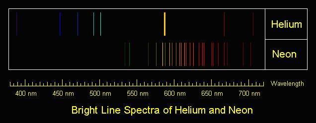
Instant Spectroscope for Viewing Lines in He-Ne Discharge
It is easy to look at the major visible lines. All it takes is a diffraction grating or prism. I made my instant spectroscope from the diffraction grating out of some sort of special effects glasses – found in a box of cereal, no less! – and a monocular (actually 1/2 of a pair of binoculars).
If you missed the Kellogg’s option, diffraction gratings can be purchased from places like Edmund Scientific. You don’t need anything fancy – any of the inexpensive ‘transmission replica gratings’ on a flat rigid substrate or mounted between a pair of plane glass plates will be fine. In a pinch, a CD disc or other optical media will work but only as a reflection grating so mounting may be a problem. A spectroscope can also be made with a prism of course but a diffraction grating is likely to be less expensive and better for this application since it is much lighter and easier to mount.
The plasma tube of a bare He-Ne laser is an ideal light source since it provides its own slit as the glow discharge is confined to the long narrow capillary bore. However, this approach can also be used with other lasers as long as the beam can be focused to a spot on a wall or screen. This will produce a ‘bright spot spectra’ instead of politically correct lines but you can’t have everything. 🙂
The diffraction grating can be used by itself but the additional optics will provide magnification and other benefits for people with less than perfect eyeballs.
Glue the diffraction grating to a cardboard sleeve that can be slipped over the (or one) objective of a monocular, binocular, or small telescope – or the telephoto lens of your camera. Orient it so that the dispersion will be vertical (since your slit will be horizontal).
Operate the HeNe tube on a piece of black velvet or paper. This will result in optimum contrast. This is best done in a darkened room where the only source of light is the laser tube itself. Just don’t trip and zap yourself on the high voltage!
A diffraction grating produces several images. The zero’th order will be the original image seen straight ahead. The important ones are the first order spectra. Tip the instrument up or down to see these. The dispersion direction – order of the colours – will depend on which way it is tipped.
Any distance beyond the closest focus of your instrument will work but being further away will reduce the effective width of the ‘slit’ resulting in the ability to distinguish more closely spaced lines.
The shear number of individual spectral lines present in the discharge is quite amazing. You will see the major red, orange, yellow, and green lines as well as some far into the blue and violet portions of the spectrum and toward the IR as well.
Bright Line Spectra of Helium and Neon
All of those shown will be present as well as many others not produced by the individual gas discharges. There are numerous IR lines as well but, of course, these will not be visible.
Place a white card in the exit beam and note where the single red output line of the He-Ne tube falls relative to the position and intensity of the numerous red lines present in the gas discharge.
As an aside, you may also note a weak blue/green haze surrounding the intense main red beam (not even with the spectroscope). This is due to the blue/green (incoherent) spectral lines in the discharge being able to pass through the output mirror which has been optimized to reflect well (>99 percent) at 632.8 nm and is relatively transparent at wavelengths some distance away from these (shorter and longer but you would need an IR sensor to see the longer ones). Since it is not part of the lasing process, this light diverges rapidly and is therefore only visible close to the tube’s output mirror.
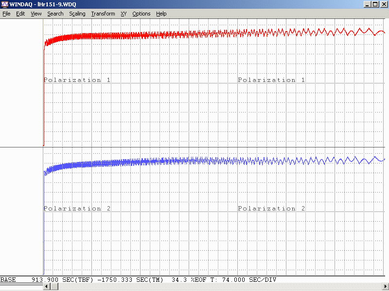
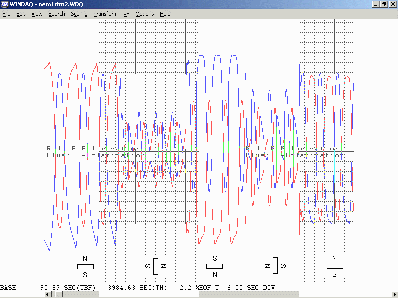
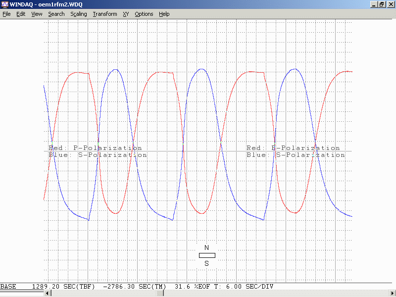
Dynamic Measurement of Discharge Spectra
The following is trivial to do if you have a recording spectrometer and external mirror He-Ne laser. For an internal mirror He-Ne laser tube, it should be possible to rock one of the mirrors far enough to kill lasing without permanently changing alignment. If you don’t have proper measuring instruments, don’t worry, this is probably in the “Gee wiz, that’s neat but of marginal practical use” department. 🙂
(From: George Werner (glwerner@sprynet.com).)
Here is an effect I found many years ago and I don’t know if anyone has pursued it further.
We had a recording spectrometer in our lab which we used to examine the incoherent light coming from the laser discharge. This spectrum when lasing was slightly different from the spectrum when not lasing, which one can expect since energy levels are redistributed. As with most detectors, ours used a chopper in the spectrometer light beam and a lock-in amplifier.
Instead of putting the chopper in the path of light going to the spectrometer, I put it in the path of the internal laser beam, so that instead of an open/closed signal going to the amplifier it was a lasing/not-lasing signal. What was recorded then was three kinds of spectrum lines: some deflected positive in the normal way, others deflected negative, and the third group were those that were unaffected by chopping, in which case when we passed over the line we only saw an increase in the noise level. Setting up such a test is easy. The hard part is interpreting the data in a meaningful way.
Other Colour Lines in Red He-Ne Laser Output
When viewing spectral lines in the actual beam of a red He-Ne laser, you may notice some very faint ones far removed from the dominant 632.8 nm line we all know and love. (This, of course, also applies to other colour He-Ne lasers.)
For He-Ne lasers, the primary line (usually 632.8 nm) is extremely narrow and effectively a singularity given any instrumentation you are likely to have at your disposal. Any other lines you detect in the output are almost certainly from two possible sources but neither is actual laser emission:
Plasma discharge – there are many strong emission lines in the actual discharge – and none of them are actually at the 632.8nm lasing wavelength! These extend from the mid-IR through the violet.Close to the output mirror, you may see some of this light seeping through especially at wavelengths in the green, blue, and violet, for which the dielectric mirrors are nearly perfectly transparent. However, such light will be quite divergent and diffuse and won’t be visible at all more than a couple of inches from the mirror.
Superradiance – As we know, He-Ne lasers can be made to operate at a variety of wavelengths other than the common 632.8nm red. The physics for these is still applicable in a red He-Ne tube but the mirrors do not have the needed reflectivity at these other wavelengths and therefore the resonator gain is too low to support true laser action. However, stimulated emission can still take place in superradiance mode – one pass down the tube and out, exiting easily for the green wavelength in particular since the dielectric mirrors are quite transparent in that region of the spectrum.The result will be a weak green beam that can sometimes be observed with a spectroscope in a very dark room room. It isn’t really quite as coherent or monochromatic as the beam from a true green He-Ne laser and probably has much wider divergence but nonetheless may be present. It may be easier to see this by using your spectroscope to view the bright spot from the laser on a white card rather than by deflecting the beam and trying to locate the green dot off to one side.Note: I have not been able to detect this effect on the short He-Ne tubes I have checked.
Since the brightness of the discharge and superradiance output should be about the same from either mirror, using the non-output end (high reflector) should prove easier (assuming it isn’t painted over or otherwise covered) since the red beam exiting from this mirror will be much less intense and won’t obscure the weak green beam.
Note that argon and krypton ion lasers are often designed for multiline output where all colours are coherent and within an order of magnitude of being equal to each other in intensity or with a knob to select an individual wavelength. Anything like this is only rarely done with He-Ne lasers because it is very difficult (and expensive) due to the low gain of the non-red lines.
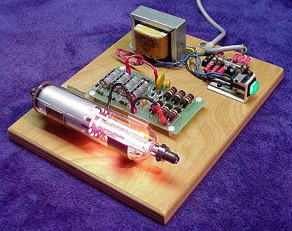
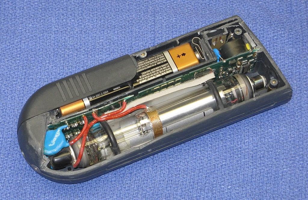
For a classroom introduction to lasers, it would be nice to have a safe setup that makes as much as possible visible to the students. Or, you may just want to have a working He-Ne laser on display in your living room! Ideally, this is an external mirror laser where all parts of the resonator as well as the power supply can be readily seen. However, realistically, finding one of these is not always that easy or inexpensive, and maintenance and adjustment of such a laser can be a pain (though that in itself IS instructive).
The next best thing is a small He-Ne laser laid bare where its sealed (internal mirror) He-Ne tube, ballast resistors, wiring, and power supply (with exposed circuit board), are mounted inside a clear Plexiglas case with all parts labelled. This would allow the discharge in the He-Ne tube to be clearly visible. The clear insulating case prevents the curious from coming in contact with the high voltage (and line voltage, if the power supply connects directly to the AC line), which could otherwise result in damage to both the person and fragile glass He-Ne tube when a reflex action results in smashing the entire laser to smithereens!
A He-Ne laser is far superior to a cheap laser pointer for several reasons:
The discharge and mirrors are clearly visible permitting the lasing process to be described in detail. Compared to this, a diode laser pointer is about as exciting as a flashlight even if you are able to extract the guts.
The beam quality in terms of coherence length, monochromaticy, shape, and stability, will likely be much higher for the He-Ne laser should you also want to use it for actual optics experiments like interferometry. (However, the first one of these – coherence length – can actually be quite good for even the some of the cheap diode lasers in laser pointers.)
For a given power level, a 632.8nm He-Ne laser will appear about 5 times brighter than a 670 nm laser pointer. 635 nm laser pointers are available but still more expensive. However, inexpensive laser pointers with wavelengths between 650 and 660 nm are becoming increasingly common and have greater relative brightness.
Important: If this see-through laser is intended for use in a classroom, check with your regulatory authority to confirm that a setup which is not explicitly CDRH approved (but with proper laser class safety stickers) will be acceptable for insurance purposes.
For safety with respect to eyeballs and vision, a low power laser – 1 mW or less – is desirable – and quite adequate for demonstration purposes.
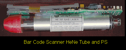
The He-Ne laser assembly from a barcode scanner is ideal for this purpose. It is compact, low power, usually runs on low voltage DC (12 V typical), and is easily disassembled to remount in a demonstration case. The only problem is that many of these have fully potted “brick” type power supplies which are pretty boring to look at. However, some have the power supply board coated with a rubbery material which can be removed with a bit of effort (well, OK, a lot of effort!).
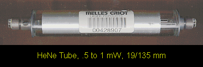
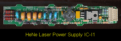
He-Ne Tube and Power Supply
For example, this is from a hand-held barcode scanner. A similar unit was separated into its component parts:
Melles Griot He-Ne TubeHe-Ne Laser Power Supply IC-I1
The power supply includes the ballast resistors. These could easily be mounted in a very compact case (as little as 3″ x 6″ x 1″, though spreading things out may improve visibility and reduce make cooling easier) and run from a 12v DC, 1 A wall adapter. Used barcode scanner lasers can often be found for $20 or less.
An alternative is to purchase a 0.5 to 1 mW He-Ne tube and power supply kit. This will be more expensive (figure $5 to $15 for the He-Ne tube, $25 to $50 for the power supply) but will guarantee a circuit board with all parts visible.
The He-Ne tube, power supply, ballast resistors (if separate from the power supply), and any additional components can be mounted with standoffs and/or cable ties to the plastic base. The tube can be separated from the power supply if desired to allow room for labels and such. However, keep the ballast resistors as near to the tube as practical (say, within a couple of inches, moving them if originally part of the power supply board). The resistors may get quite warm during operation so mount them on standoffs away from the plastic. Use wire with insulation rated for a minimum of 10 kV. Holes or slots should be incorporated in the side panels for ventilation – the entire affair will dissipate 5 to 10 Watts or more depending on the size of the He-Ne tube and power supply.
When attaching the He-Ne tube, avoid anything that might stress the mirror mounts. While these are quite sturdy and it is unlikely that any reasonable arrangement could result in permanent damage, even a relatively modest force may result in enough mirror misalignment to noticeably reduce output power. And, don’t forget that the mirror mounts are also the high voltage connections and need to be well insulated from each other and any human contact! The best option is probably to fasten the tube in place using Nylon cable ties, cable clamps, or something similar around the glass portion without touching the mirror mounts at all (except for the power connections).
Provide clearly marked red and black wires (or binding posts) for the low voltage DC or a line cord for AC (as appropriate for the power supply used), power switch, fuse, and power-on indicator. Label the major components and don’t forget the essential CDRH safety sticker (Class II for less than 1 mW or Class IIIa for less than 5 mW).
See:
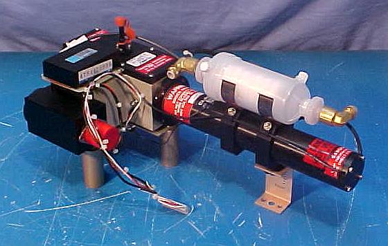
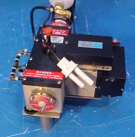
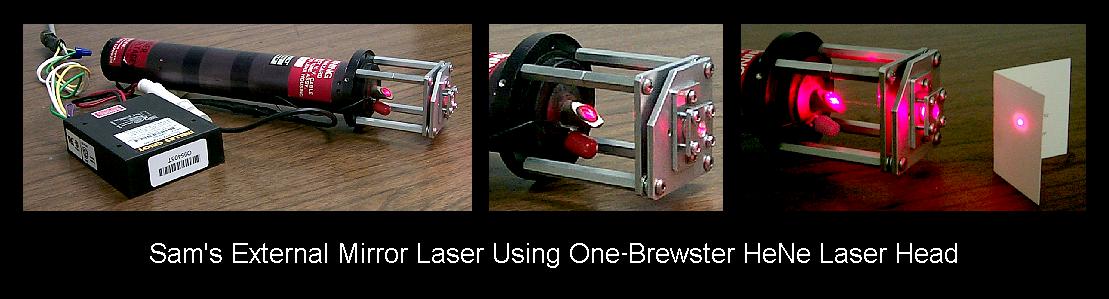
Sam’s Demo He-Ne Laser
Above, as an example (minus the Plexiglas safety cover), contructed from the guts of a surplus Gammex laser (probably part of a patient positioning system for a CT or MRI scanner). The discrete line operated power supply is simple with the HV transformer, rectifier/doubler, filter, multiplier, and ballast resistors easily identified. This would make an ideal teaching aid.
Rather than having a see-through laser that just outputs a laser beam (how boring!), consider something that would allow access to the internal cavity, swapping of optics, and modulation of beam power. OK, perhaps the truly ultimate demo laser would use a two-Brewster tube allowing for interchangeable optics at both ends, be tunable to all the He-Ne spectral lines, and play DVD movies. 🙂 We’ll have to settle for something slightly less ambitious (at least until pigs fly). Such a unit could consist of the following components:
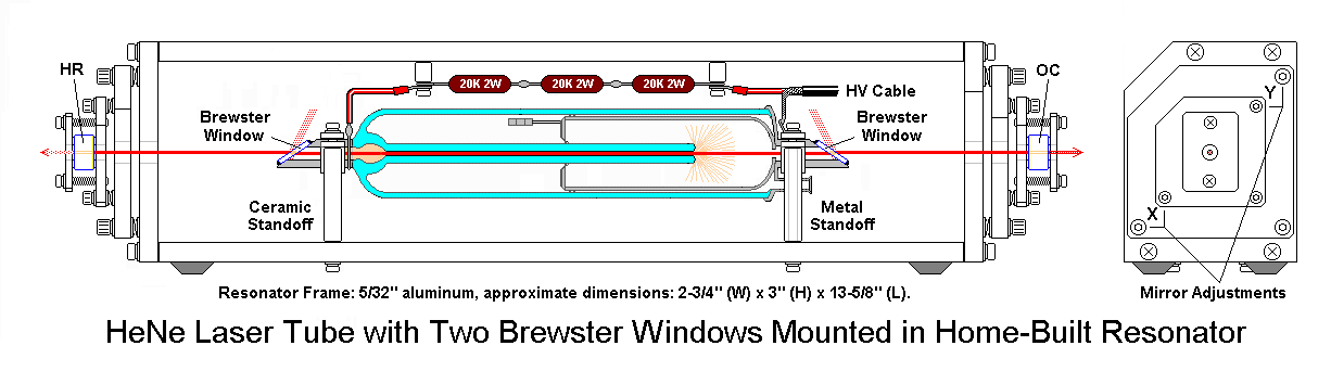
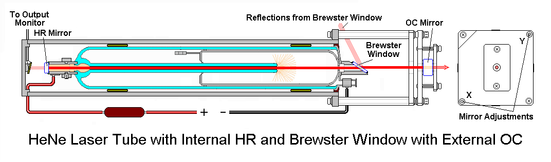
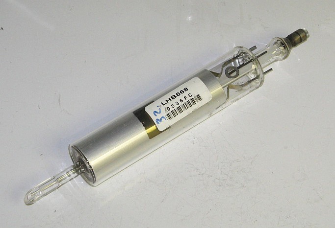
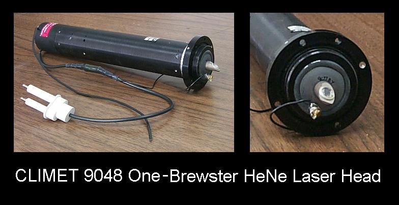
One-Brewster He-Ne laser tube or head. This can be something similar to the Melles Griot 05-LHB-570 tube or the Climet 9048 head which contains this tube. These have a Brewster window at one end and an internal HR mirror with a 60 cm Radius of Curvature (RoC) at the other. Their total length is about 10.5 inches (260 mm).
Adjustable mirror mount with limited range to permit easy mirror tweaking but with minimal chance of getting alignment really messed up. A basic design using a pair of plates with X and Y adjustment screws and a common pivot with lock washers for the compliance springs would be adequate.
Interchangeable mirrors of RoC = 60 cm and reflectance of 98% to 99.5% (OC) and 99.999% (HR in place of OC to maximize internal photon flux). These may be salvaged from a dead 3 to 5 mW He-Ne laser tube. Those from a tube like the Spectra-Physics 084-1 would be suitable. It would be best to install the mirrors in protective cells for ease of handling.
Baseplate to mount the laser and optics with the internal HR of the one-Brewster tube/head about 60 cm from the external mirror to create a confocal cavity – about one half of which is external and accessible. An option would be to put the external mirror mount on a movable slide to allow its position to be changed easily.
Power supply with adjustable current and modulation capability. This would provide the ability to measure output power versus current and to use the laser as an optical transmitter with a solar cell based receiver.
Plexiglas box to house and protect the laser and power supply (as well as inquisitive fingers from high voltage) with part of one side open to allow access to the internal photons.
Everything needed for such a setup is readily available or easily constructed at low cost but you’ll have to read more to find out where or how as each of the components are dealt with in detail elsewhere in Sam’s Laser FAQ (but I won’t tell you exactly where – these are all the hints you get for this one!).
A system like this could conceivably be turned into an interactive exhibit for your local science museum – assuming they care about anything beyond insects and the Internet these days. 🙂 There are some more details in the next section.
Guidelines for a Demonstraton One-Brewster He-Ne Laser
The following suggestions would be for developing a semi-interactive setup whereby visitors can safely (both for the visitor and the laser) adjust mirror alignment and possibly some other parameters of laser operation. The type of one-Brewster (1-B) He-Ne laser tube like the Melles Griot 05-LHB-570. Note that the 05-LHB-570 is a wide bore tube that runs massively multi (transverse) mode with most mirrors configurations unless an intracavity aperture is added. This is actually an advantage for several reasons:
The multi-transverse mode structure is interesting in itself and provides additional options for showing how it can be controlled.
Mirror alignment is easier and the tube will lase over a much wider range of mirror orientation.
Output power is higher for its size and power requirements.
Here are some guidelines for designing an interactive exhibit:
Mount the 1-B tube in a clear plastic (Plexiglas) enclosure with some ventilation holes to allow for cooling but make sure any parts with high voltage (anode, ballast resistors if not insulated) are safely protected from the curious. Provide a small hole lined up with the Brewster window for the intracavity beam. However, even if the B-window is at the cathode-end of the tube, don’t allow it to be accessible as the first fingerprint will prevent lasing entirely.
Put the power supply in a safe place inside another clear plastic box if desired. I’d recommend controlling it with a time switch that will turn it on for perhaps 10 minutes with a push of a button. This is a tradeoff between wear from running the laser all the time and wear from repeated starts. Don’t forget the fuse!!!
Orient the tube so the B-windows is either on the side or facing down. This will minimize dust collection and permit the rig to operate for many hours or days without the need for even dusting.
Use an output mirror with an RoC from 50 cm to planar and reflectivity of 98 to 99.5 percent at 632.8 nm. The specific parameters and distance will affect the beam size, mode structure, and output power. A shorter RoC will limit the distance over which lasing will take place but will be somewhat easier to align.
Use a decent quality mirror mount like a Newport MM-1 for the output mirror. Once it’s secured, arrange for the adjustment screws to be accessible to visitors but limit the range of rotation to less than one turn and mark the location of each screw where lasing is peaked. That way, no amount of fiddling will lose lasing entirely.
The distance between the mirror and tube can be fixed or adjustable:
For a fixed location, a distance of a few inches between the laser enclosure and mirror mount is recommended. This is enough space to install an aperture or Brewster plate. Or a hand to show that the beam is only present with the resonator is complete, not just a red light inside! But, it’s short enough that alignment is still easy.
For added excitement, put the mirror mount on a precision rail to permit the distance to be varied from 0 to at least 45 cm from the B-window. Then, it will be possible to see how the mode structure changes with distance. This will depend on the RoC of the mirror as well.
Another option is to provide various things like an iris diaphragm, thin wires and/or a cross-hair, adjustable knife edge, Brewster plate that can be oriented, etc. However, some care will be needed in making these useful without a lot of hand holding.
Weatherproofing a He-Ne Laser
If you want to use a He-Ne laser outside or where it is damp or very humid, it will likely be necessary to mount the tube and power supply inside a sealed box. Otherwise, stability problems may arise from electrical leakage or the tube may not start at all. There will then be several additional issues to consider:
Heat dissipation – For a small He-Ne tube (say 1 mW), figure this is like a 10 to 15 W bulb inside a plastic box. If you make the box large enough (e.g., 3″ x 5″ x 10″), there should be enough exterior surface area to adequately remove the waste heat.
Getting the beam out – A glass window (e.g., quality microscope slide) mounted at a slight angle (to avoid multiple reflections back to the He-Ne tube output mirror) is best. However, a Plexiglas window may be acceptable (i.e., just pointing the laser at a slight angle through the plastic case). A Brewster angle window should be used only if the He-Ne tube is a linearly polarized type (not likely for something from a barcode scanner) and then the orientation and angle must be set up for maximum light transmission.
Condensation on the optics and elsewhere – This may be a problem on exposed surfaces if they are colder than the ambient conditions. Let the entire laser assembly warm up before attempting to power it up!
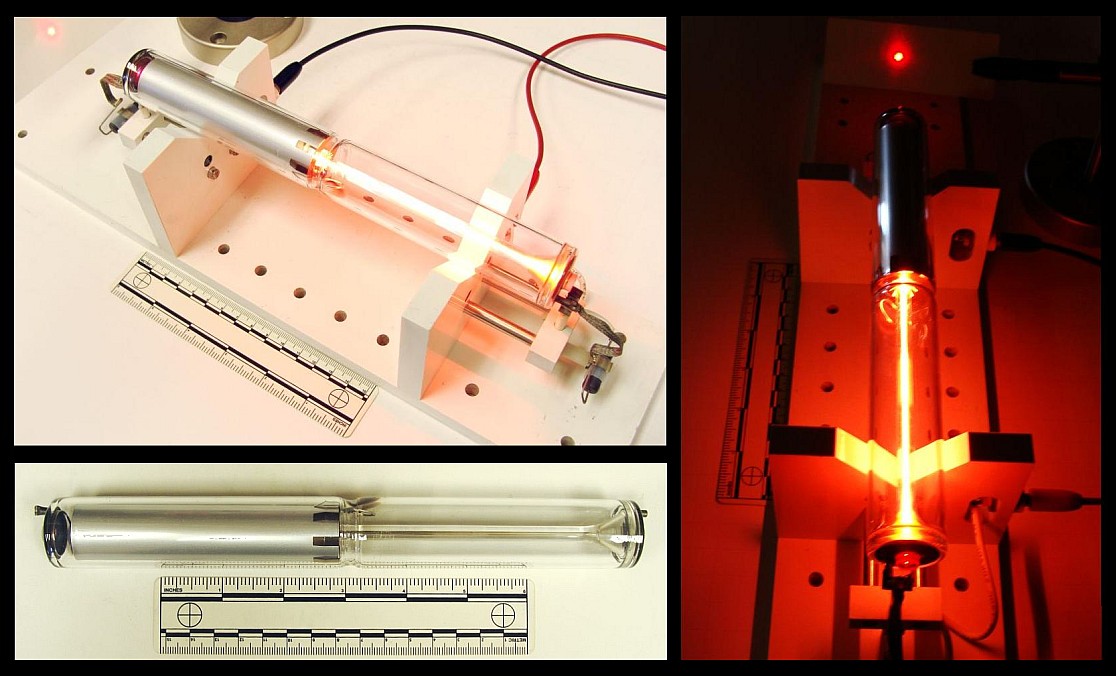
Prior to the introduction of the CD player, the red He-Ne laser was by far the most common source of inexpensive coherent light on the planet. The following are some typical physical specifications for a variety of red (632.8 nm) He-Ne tubes (all are single transverse mode – TEM00):
   Output       Tube Voltage       Tube         Tube Size
   Power        Operate/Start     Current      Diam/Length
 ------------  ---------------  ------------  -------------
  0.3-0.5 mW    0.8-1.0/6  kV    3.0-4.0 mA     19/135 mm
  0.5-1 mW       .9-1.0/7  kV    3.2-4.5 mA     25/150 mm
   1-2 mW       1.0-1.4/8  kV    4.0-5.0 mA     30/200 mm
   2-3 mW       1.1-1.7/8  kV    4.0-6.5 mA     30/260 mm
   3-5 mW       1.7-2.4/10 kV    4.5-6.5 mA     37/350 mm
   5-10 mW      2.4-3.1/10 kV    6.5-7.0 mA     37/440 mm
  10-15 mW      3.0-3.5/10 kV    6.5-7.0 mA     37/460 mm
  15-25 mW      3.3-4.0/10 kV    6.5-7.0 mA     37/600 mm
  25-35 mW      4.0-5.2/12 kV    7.0-8.0 mA     42/900 mm
Where:
Power Output is the minimum beam power after a specified warm up period over the spec’d life of the tube.
Tube Operating Voltage is the voltage across the bare tube at the nominal operating current.
Tube Start Voltage is the minimum voltage across the bare tube required to guarantee starting.
Tube Size is generally the maximum diameter of the tube envelope and the total length from the outer surfaces of the mirrors.
Tubes like this are generally available in both random and linearly polarized versions which are otherwise similar with respect to the above characteristics (for red tubes at least, more below).
At least one other basic specification may be critical to your application: Which end of the tube the beam exits! There is no real preference from a manufacturing point of view for red He-Ne lasers. (For low gain “other-colour” He-Ne laser tubes, it turns out that anode output results is slightly higher gain and thus slightly higher output for the typical hemispherical cavity because it better utilizes the mode volume.) However, this little detail may matter a great deal if you are attempting to retrofit an existing barcode scanner or other piece of equipment where the tube clips into a holder or where wiring is short, tight, or must be in a fixed location. For example, virtually all cylindrical laser heads require that the beam exits from the cathode-end of the tube. It is possible that you will be able to find two versions of many models of He-Ne tubes if you go directly to the manufacturer and dig deep enough. However, this sort of information may not be stated where you are buying surplus or from a private individual, so you may need to ask.
The examples above (as well as all of the other specifications in this and the following sections) are catalog ratings, NOT what might appear on the CDRH safety sticker (which is typically much higher). See the section: About Laser Power Ratings for info on listed, measured, and CDRH power ratings.
Note how some of the power levels vary widely with respect to tube dimensions, voltage, and current. Generally, higher power implies a longer tube, higher operating/start voltages, and higher operating current – but there are some exceptions. In addition, you will find that physically similar tubes may actually have quite varied power output. This is particularly evident in the manufacturers’ listings. (See the chapter: A HREF=”laserhcl.htm#hcltoc”>Commercial Unstabilized HeNe Lasers.)
These specifications are generally for minimum power over the guaranteed life of the tube. New tubes and individual sample tubes after thousands of hours may be much higher – 1.5X is common and a “hot” sample may hit 2X or more. My guess is that for tubes with identical specifications in terms of physical size, voltage, and current, the differences in power output are due to sample-to-sample variations. Thus, like computer chips, they are selected after manufacture based on actual performance and the higher power tubes are priced accordingly! This isn’t surprising when considering the low efficiency at which these operate – extremely slight variations in mirror reflectivity and trace contaminants in the gas fill can have a dramatic impact on power output.
I have a batch of apparently identical 2 mW Aerotech tubes that vary in power output by a factor of over 1.5 to 1 (2.6 to 1.7 mW printed by hand on the tubes indicating measured power levels at the time of manufacture).
And, power output also changes with use (and mostly in the days of soft-sealed tubes, just with age sitting on the shelf):
(From: Steve Roberts.)
“I have a neat curve from an old Aerotech catalogue of He-Ne laser power versus life. The tubes are overfilled at first, so power is low. They then peak at a power much higher than rated power, followed by a long period of constant power, and then they SLOWLY die. It’s not uncommon for a new He-Ne tube to be in excess of 15% greater than rated power.”
And the answer to your burning question is: No, you cannot get a 3 mW tube to output 30 mW – even instantaneously – by driving it 10 times as hard!
I have measured the operating voltage and determined the optimum current (by maximizing beam intensity) for the following specific samples – all red (632.8 nm) tubes from various manufacturers. (The starting voltages were estimated.):
   Output     Tube Voltage       Tube         Supply Voltage     Tube Size
   Power      Operate/Start     Current        (75K ballast)    Diam/Length
 ----------  ---------------  ------------   ----------------  -------------
    .8 mW        .9/5  kV        3.2 mA           1.1 kV         19/135 mm
   1.0 mW       1.1/7  kV        3.5 mA           1.4 kV         25/150 mm
   1.0 mW       1.1/7  kV        3.2 mA           1.4 kV         25/240 mm
   2.0 mW       1.2/8  kV        4.0 mA           1.5 kV         30/185 mm
   3.0 mW       1.6/8  kV        4.5 mA           1.9 kV         30/235 mm
   5.0 mW       1.7/10 kV        6.0 mA           2.2 kV         37/350 mm
  12.0 mW       2.5/10 kV        6.0 mA           2.9 kV         37/475 mm
Melles Griot, Uniphase, Siemens, PMS, Aerotech, and other HeNe tubes all show similar values.
The wide variation in physical dimensions also means that when looking at descriptions of He-Ne lasers from surplus outfits or the like, the dimensions can only be used to determine an upper (and possibly lower) bound for the possible output power but not to determine the exact output power (even assuming the tube is in like-new condition). Advertisements often include the rating on the CDRH safety sticker (or say ‘max’ in fine print). This is an upper bound for the laser class (e.g., Class IIIa), not what the particular laser produces or is even capable of producing. It may be much lower. For example, that Class IIIa laser showing 5 mW on the sticker, may actually only be good for 1 mW under any conditions! The power output of a He-Ne laser tube is essentially constant and cannot be changed significantly by using a different power supply or by any other means. See the section: Buyer Beware for Laser Purchases.
In addition to power output, power requirements, and physical dimensions, key performance specifications for He-Ne lasers also include:
Beam Diameter at the laser’s output aperture and beam profile (Gaussian TEM00 for most small He-Ne laser tubes).
Beam Divergence (probably far field ignoring beam waist). Note that this may not always be the same as the expected value from the diffraction limit based on beam/bore diameter as it also depends on the combination of the HR and OC mirror (inside) curvature and the shape of the exterior surface of the OC.
Mode Spacing (frequency) between the multiple longitudinal modes that are active simultaneously in all but single mode frequency stabilized lasers.
With manufacturers like Aerotech, Melles Griot, and Siemens, a certain amount of information can be determined from the model number. For example, here is how to decipher most of those from Melles Griot (e.g., 05-LHP-121-278):
All Melles Griot He-Ne laser tubes and power supplies start with 05. Matched systems may start with 25 (e.g., laser head and lab-style power supply).
The first letter will be an L for all He-Ne laser tubes and heads except for perpendicular window terminated tubes (in which case it will be W – this is inconsistent with the rest of their numbering but who am I to complain!), and some of their self contained lasers where it will be S.
The second letter will be one of: H = red (632.8 nm), G = green (543.5 nm), Y = yellow (594.1 nm), O = orange (611.9 nm), or I = infra-red (1,523 or 3,391 nm). A couple of self contained red lasers use R for red but for most, I guess they got stuck using H (presumably denoting He-Ne) before ‘other colour’ He-Ne lasers were part of their product line. And, their stabilized He-Ne lasers use a T here. Confused yet? 🙂
The third letter will be one of: R = Randomly polarized, L = linearly polarized, or B = Brewster window at one or both ends.
The following three digit number determines the physical characteristics of the laser tube to some extent. Unfortunately, there may be no direct mathematical relationship of this number to anything useful. As will be seen below, for some models, it (or some of its digits) sort of correlates with output power or length but for others, they might as well be totally random! However, it does appear as though an identical set of numbers among different colour tubes (see below) will denote similar physical size tubes at least.
If there are additional numbers, they relate to a special variation on the basic design done for a particular customer. For example, this might be a different curvature on the outer surface of the output mirror to provide a non-standard divergence to eliminate the need for an additional lens in a barcode scanner. Or, an external window for protection from the elements or to deliberately reduce output power. Go figure. 🙂 It may also just denote a specific configuration like -249 (meaning 115 VAC operation, kind of arbitrary, huh?) or -55 (meaning 5.5 mA). In these cases, the user may be able to modify the settings (flip a switch or twiddle a pot) but the warranty may then be void.
The vast majority of Melles Griot lasers you are likely to come across will follow this numbering scheme though there are some exceptions, especially for custom assemblies. (Some surplus places drop the leading ’05-‘ when reselling Melles Griot laser tubes or heads so an 05-LHP-120 would become simply an LHP-120.)
For other manufacturers like Spectra-Physics, the model numbers are totally arbitrary!
He-Ne Tubes of a Different Colour
Although a red beam is what everyone thinks of when a He-Ne laser is discussed, He-Ne tubes producing green, yellow, and orange beams, as well as several infra-red (IR) wavelengths, are also manufactured. However, they are not found as often on the surplus market because they are not nearly as common as the red variety. In terms of the number of He-Ne lasers manufactured, red is far and away the most popular, with all the others combined accounting for only 1 to 2 percent of the total production. In order of decreasing popularity, it’s probably: red, green, yellow, infra-red (all IR wavelengths), orange. Non-red tubes are also more expensive when new since for a given power level, they must be larger (and thus have higher voltage and current ratings) due to their lower efficiency (the spectral lines being amplified are much weaker than the one at 632.8 nm). Operating current for non-red He-Ne tubes is also more critical than for the common red variety so setting these up with an adjustable power supply or adjusting the ballast resistance for maximum output is recommended.
Maximum available power output is also lower – rarely over 2 mW (and even those tubes are quite large (see the tables below). However, since the eye is more sensitive to the green wavelength (543.5 nm) compared to the red (632.8 nm) by more than a factor of 4, a lower power tube may be more than adequate for many applications. Yellow (594.1 nm) and orange (611.9 nm) He-Ne lasers appear more visible by factors of about 3 and 2 respectively compared to red beams of similar power.
Infrared-emitting He-Ne lasers exist as well. In addition to scientific uses, these were used for testing in the Telecom industry before sufficiently high quality diode lasers became available.Yes, you can have a He-Ne tube and it will light up inside (typical neon glow), but if there is no output beam (at least you cannot see one), you could have been sold an infrared He-Ne tube. However, by far the most likely explanation for no visible output beam is that the mirrors are misaligned or the tube is defective in some other way. Unfortunately, silicon photodiodes or the silicon sensors in CCD or CMOS cameras do not respond to any of the He-Ne IR wavelengths, so the only means of determining if there is an IR beam are to use a GaAs photodiode, IR detector card, or thermal laser power meter. IR He-Ne tubes are unusual enough that it is very unlikely you will ever run into one. However, they may turn up on the surplus market especially if the seller doesn’t test the tubes and thus realize that these behave differently – they are physically similar to red (or other colour) He-Ne tubes except for the reflectivity of the mirrors as a function of wavelength. (There may be some other differences needed to optimize each color like the He:Ne ratio, isotope purity, and gas fill pressure, but the design of the mirrors will be the most significant factor and the one that will be most obvious with a bare eyeball, though the color of the discharge may be more pink for green He-Ne tubes and more orange and brighter for IR He-Ne tubes compared to red ones, more below.) Even if the model number does not identify the tube as green, yellow, orange, red, or infra-red, this difference should be detectable by comparing the appearance of its mirrors (when viewed down the bore of an UNPOWERED tube) with those of a normal (known to be red) He-Ne tube. (Of course, your tube could also fail to lase due to misaligned or damaged mirrors or some other reason.
As noted above, the desired wavelength is selected and the unwanted wavelengths are suppressed mostly by controlling the reflectivity functions of the mirrors. For example, the gains of the green and yellow lines (yellow may be stronger) are both much much lower than red and separated from each other by about 50 nm (543.5 nm versus 594.1 nm). To kill the yellow line in a green laser, the mirrors are designed to reflect green but pass yellow. I have tested the mirrors salvaged from a Melles Griot 05-LGP-170 green He-Ne tube (not mine, from “Dr. Destroyer of Lasers”). The HR (High Reflector) mirror has very nearly 100% reflectivity for green but less than 25% for yellow. The OC (Output Coupler) also has a low enough reflectivity for yellow (about 98%) such that it alone would prevent yellow from lasing. The reflectivities for orange, red, and IR, are even lower so they are also suppressed despite their much higher gain, especially for the normal red (632.8 nm) and even stronger mid-IR (3,391 nm) line.
However, to manufacture a tube with optimum and stable output power, it isn’t sufficient to just kill lasing for unwanted lines. The resonator must be designed to minimize their contribution to stimulated emission – thus the very low reflectivity of the HR for anything but the desired green wavelength. Otherwise, even though sustained oscillation wouldn’t be possible, unwanted colour photons would still be bouncing back and forth multiple times stealing power from the desired colour. The output would also be erratic as the length of the tube changed during warm up (due to thermal expansion) and this affected the longitudinal mode structure of the competing lines relative to each other. Some larger He-Ne lasers have magnets along the length of the tube to further suppress (mostly) the particularly strong mid-IR line at 3,391 nm. (See the section: Magnets in High Power or Precision HeNe Laser Heads.)
In addition, you can’t just take a tube designed for a red laser, replace the mirrors, and expect to get something that will work well – if at all – for other wavelengths. For one thing, the bore size and mirror curvature for maximum power while maintaining TEM00 operation are affected by wavelength.
Furthermore, for these other colour He-Ne lasers which depend on energy level transitions which have much lower gain than red – especially the yellow and green ones – the gas fill pressure, He:Ne ratio, and isotopic composition and purity of the helium and neon, will be carefully optimized and will be different than for normal red tubes.
Needless to say, the recipes for each type and size laser will be closely guarded trade secrets and only a very few companies have mastered the art of other colour He-Ne lasers, especially for high power (in a relative sort of way) in yellow and green. I am only aware of four companies that currently manufacture their own tubes: Melles Griot, Research Electro-Optics, Uniphase, and LASOS, with the last two having very few models to choose from. Others (like Coherent) simply resell lasers under their own name.
And, the answer to that other burning question should now be obvious: No, you can’t convert an ordinary red internal mirror He-Ne tube to generate some other colour light as it’s (almost) all done with mirrors and they are an integral part of the tube. 🙂 Therefore, your options are severely limited. As in: There are none. (However, going the other way, at least as a fun experiment, may be possible. For a laser with external mirrors, a mirror swap may be possible (though the cavity length may be insufficient to resonate with the reduced gain of other-colour spectral lines once all loses taken into consideration). But realistically, this option doesn’t even exist where the mirrors are sealed into the tube.
There are also a few He-Ne lasers that can output more than one of the possible colors simultaneously (e.g., red+orange, orange+yellow) or selectively by turning knob (which adjusts the angle of a Littrow or other similar dispersion prism) inside the laser cavity using a Brewster window He-Ne tube). But such lasers are not common and are definitely very expensive. So, you won’t likely see one for sale at your local hamfest – if ever! One manufacturer of such lasers is Research Electro-Optics (REO). See the section: Research Electro-Optics’s Tunable HeNe Lasers.
However, occasionally a He-Ne tube turns up that is ‘defective’ due to incorrect mirror reflectivities or excessive gain or magic 🙂 and actually outputs an adjacent colour in addition to what it was designed to produce. I have such a tube that generates about 3 mW of yellow (594.1 nm) and a fraction of a mW of orange (611.9 nm) but isn’t very stable – power fluctuates greatly as it warms up. Another one even produces the other orange line at 611.9 nm, and it’s fairly stable. But, finding magic ‘defective’ tubes such as these by accident is extremely unlikely though I’ve heard of the 640.1 nm (deep red) line showing up on some supposedly good normal red (632.8 nm) He-Ne tubes.
As a side note: It is strange to see the more or less normal red-orange glow in a green He-Ne laser tube but have a green beam emerging. A diffraction grating or prism really shows all the lines that are in the glow discharge. Red through orange, yellow and green, even several blue lines (though they are from the helium and can’t lase under any circumstances)!! The IR lines are present as well – you just cannot see them.
Actually, the colour of the discharge may be subtly different for non-red He-Ne tubes due to modified gas fill and pressure. For example, the discharge of green He-Ne tubes may appear more pink compared to red tubes) which are more orange), mostly due to lower fill pressure. The fill mix and pressure on green He-Ne tubes is a tricky compromise among several objectives that conflict to some extent including lifetime, stability (3.39µm competition), and optical noise. This balancing act and the lower fill pressure are why green He-Ne tubes don’t last as long as reds. Have I totally confused you, colour-wise? 🙂
The expected life of ‘other colour’ He-Ne tubes is generally much shorter than for normal red tubes. This is something that isn’t widely advertised for obvious reasons. Whereas red He-Ne tubes are overfilled initially (which reduces power output) and they actually improve with use to some extent as gas pressure goes down, this luxury isn’t available with the low gain wavelengths – especially green – everything needs to be optimal for decent performance.
The discharge in IR He-Ne tubes may be more orange and brighter due to a higher fill pressure. Again, this is due to the need to optimize parameters for the specific wavelength.
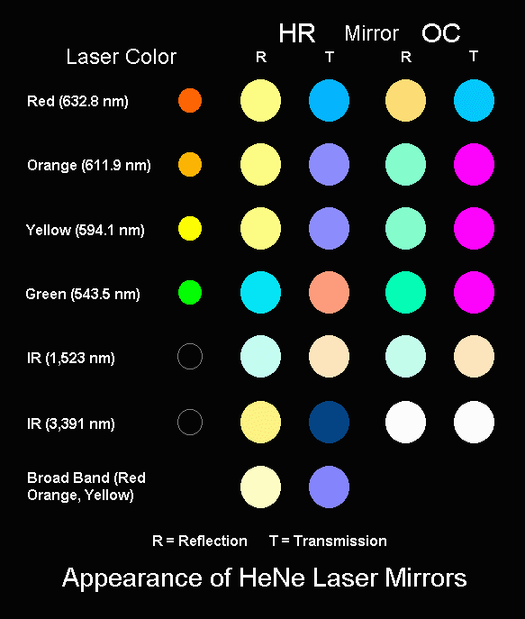
Determining He-Ne Laser Colour from the Appearance of the Mirrors
Although most He-Ne lasers are the common red (632.8 nm) variety (whose beam actually appears orange-red), you may come across unmarked He-Ne tubes and just have to know what colour output the produce without being near a He-Ne laser power supply.
Since the mirrors used in all He-Ne lasers are dielectric – functioning as a result of interference – they have high reflectivity only around the laser wavelength and actually transmit light quite well as the wavelength moves away from this peak. By transmitted light, the appearance will tend to be a colour which is the complement of the laser’s output – e.g., cyan or blue-green for a red tube, pink or magenta for a green tube, blue or violet for a yellow tube. Of course, except for the IR variety, if the tube is functional, the difference will be immediately visible when it is powered up!
The actual appearance may also depend on the particular manufacturer and model as well as the length/power output of the laser (which affects the required reflectivity of the OC), as well as the revision number of your eyeballs. 🙂 So, there could be considerable variation in actual perceived colour. Except for the blue-green/magenta combination which pretty much guarantees a green output He-Ne tube, more subtle differences in colour may not indicate anything beyond manufacturing tolerances.
Appearance of He-Ne Laser Mirrors
The chart above in conjunction with will help to identify your unmarked He-Ne tube. (For accurate rendition of the graphic, your display should be set up for 24 bit colour and your monitor should be adjusted for proper colour balance.)
      HeNe Laser          High Reflector (HR)          Output Coupler (OC)
   Color  Wavelength   Reflection   Transmission    Reflection   Transmission
 ------------------------------------------------------------------------------
    Red    632.8 nm    Gold/Copper      Blue        Gold/Yellow   Blue/Green
   Orange  611.9 nm   Whitish-Gold      Blue       Metallic Green   Magenta
   Yellow  594.1 nm   Whitish-Gold      Blue       Metallic Green   Magenta
   Green   543.5 nm   Metallic Blue  Red/Orange    Metallic Green   Magenta

   Broadband (ROY)    Whitish-Gold      Blue

    IR     1,523 nm    Light Green  Light Magenta   Light Green  Light Magenta
    IR     3,391 nm       Gold (Metal) Coated         Neutral        Clear
The entry labelled ‘Broadband’ relates to the HR mirror in some unusual multiple colour (combinations of red and/or orange and/or yellow) internal mirror tubes as well as those with an internal HR and Brewster window for external OC optics. And, the yellow and orange tubes may actually use broad band HRs. The OCs would then be selected for the desired wavelength(s) and may also have a broad band coating.
For low gain tubes, they play games with the coatings. I guess it isn’t possible to just make a highly selective coating for one wavelength that’s narrow enough to have low reflectivity at the nearby lines so they won’t lase. So, one mirror will be designed to fall off rapidly on one side of the design wavelength, the other mirror on the other side. That’s one reason front and back mirrors on yellow and green tubes in particular have very different appearances.
As noted, depending on laser tube length/output power, manufacturer, and model, the appearance of the mirrors can actually vary quite a bit but this should be a starting point at least. For example, I have a Melles Griot 05-LHR-170 He-Ne laser tube that should be 594.1 nm (yellow) but actually outputs some 604.6 nm (orange) as well. It’s mirror colours for the HR and OC are almost exactly opposite of those I have shown for the yellow and orange tubes! I don’t know whether this was intentional or part of the problem And, while from this limited sample, it looks like the OCs for orange, yellow, and green He-Ne lasers appear similar, I doubt that they really are in the area that counts – reflectivity/transmission at the relevant wavelengths.
More on Other Colour He-Ne Lasers
Here are some comments on the difficulty of obtaining useful visible output from He-Ne lasers at wavelengths other than our friendly red (632.8 nm):
(From: Steve Roberts.)
You do need a isotope change in the gases for green, and a He:Ne ratio change for the other orange and yellow lines. In addition, the mirrors to go to another line will have a much lower output transmission. The only possible lines you’ll get on a large frame He-Ne laser will be the 611.9 nm orange and 594.1 nm yellow. The green requires external mirror tubes in excess of a meter and a half long and a Littrow prism to overcome the Brewster losses and suppress the IR.
The original work on green was done by Rigden and Wright. The short tubes have lower losses because they have no Brewsters and thus can concentrate on tuning the coatings to 99.9999% reflectivity and maximum IR transmission. There is one tunable low power unit on the market that does 6 lines or so, but only 1 line at a time, and the $6,000 cost is kind of prohibitive for a few milliwatts of red and fractional milliwatt powers on the other lines. But, it will do green and has the coatings on the back side of the prism to kill the losses.
Also look for papers by Erkins and Lee. They are the fellows who did the green and yellow for Melles Griot and they published one with the energy states as part of a poster session at some conference. Melles Griot used to hand it out, that’s how I had a copy, recently thrown away.
Even large He-Ne lasers such as the SP-125 (rated at 50mW of red) will only do about 20mW of yellow, with a 35mW SP-127 you’re probably only looking at 3 to 5mW of yellow. And, for much less then the cost of the custom optics to do a conversion, you can get two or three 4 to 5 mW yellow heads from Melles Griot. I know for a fact that a SP-127 only does about 3mW of 611.9 with a external prism and a remote cavity mirror, when it does 32mW of 632.8nm.
So in the end, unless you have a research use for a special line, it’s cheaper to dig up a head already made for the line you seek, unless you have your own optics coating lab that can fabricate state-of-the-art mirrors.
I have some experience in this, as I spent months looking for a source of the optics below $3,000.
(From: Sam.)
I do have a short (265 mm) one-Brewster He-Ne tube (Melles Griot 05-LGB-580) with its internal HR optimized for green that operates happily with a matching external green HR mirror (resulting in a nice amount of circulating power) but probably not with anything having much lower reflectivity to get a useful output beam. In fact, I could not get reliable operation even with the HR from a dead green He-Ne laser tube as the Brewster window would not remain clean enough for the time required to align the mirror.
I would expect an SP-127 to do more than 3 to 5 mW of yellow, my guess would be 10 to 15 mW with optimized mirrors but no tuning prism. If I can dig up appropriate mirrors, I intend to try modifying an SP-127 to make it tunable and/or do yellow or green. 🙂
You can find 640.1 nm in a lot of red He-Ne lasers. I have a paper on it somewhere, and cavity design can influence it to a large extent. If you have a decent quality grating, it’s pretty easy to pick up. 629 nm is the one you don’t see too much.
I’m no physicist, but the lower gain lines can lase simultaneously with the higher gain lines, no problem, as long as there is sufficient gain available in the plasma. It’s really pretty easy to get a He-Ne laser to output on all lines at the same time (if you have the right mirrors). The trick is optimizing the bore-to-mode ratio, gas pressure, and isotope mixture to get good TEM00 power. Usually the all-lines He-Ne lasers are multi (transverse) mode. I don’t know of anyone who makes them commercially though – at least not intentionally.
Steve’s Comments on Superradiance and the 3.39µm He-Ne Laser
Generally, when a gas laser is superradiant, there is a limit to its maximum power output (with exceptions for nitrogen and copper vapour laser, although nitrogen’s upper limit is defined by the maximum cavity length into which you can generate a 300ns or less excitation pulse.
The 3.39µm He-Ne laser’s gain is still, like all other He-Ne lines limited by a wall collision to return the excited atoms to the ground state. 3.39 µm He-Ne lasers have larger bores then normal He-Ne lasers, and the bores are acid etched to fog them and create more surface area, but still the most power I’ve ever seen published was 40 mW – nothing to write home about. The massive SP-125, the largest commercial He-Ne laser, could be ordered with a special tube and special optics for 3.39µm, and it still only did about 1/3rd the visible power. Superradiance and ultimate power are not tied together.
The reason 3.39µm got all the writeups it did was that it started on the same upper state as all the other He-Ne lines, was easily noticed when it sapped power from the visible line, and was, at the time, a exotic wavelength for which there were few other sources.
In the first He-Ne lasers (see the diagram below), exciting the gas atoms to the higher energy level was accomplished by coupling a radio frequency (RF) source (i.e., a radio transmitter) to the tube via external electrodes. Modern He-Ne lasers almost always operate on a DC discharge via internal electrodes.
Early He-Ne lasers were also quite large and unwieldy in comparison to modern devices. A laser such as the one depicted above was over 1 meter in length but could only produce about 1 mW of optical beam power! The associated RF exciter was as large as a microwave oven. With adjustable mirrors and a tendency to lose helium via diffusion under the electrodes, they were a finicky piece of laboratory apparatus with a lifetime measured in hundreds of operating hours.
In comparison, a modern 1 mW internal mirror He-Ne laser tube can be less than 150 mm (6 inches) in total length, may be powered by a solid state inverter the size of half a stick of butter, and will last more than 20,000 hours without any maintenance or a noticeable change in its performance characteristics.
The following applies to most of the inexpensive internal mirror low to medium power (0.5 to 5 mW) HeNe tubes available on the surplus market. Depending on the original application, the actual laser tube may be enclosed inside a laser head or arrive naked. 🙂
This fabulous ASCII rendition of a typical small He-Ne laser tube should make everything perfectly clear. 🙂
The main beam may emerge from either end of the tube depending on its design, not necessarily the cathode-end as shown. (For most applications it doesn’t matter. However, when mounted in a laser head, it makes sense to put the anode and high voltage at the opposite end from the output aperture both for safety and to minimize the wiring length.) A much lower power beam will likely emerge from the opposite end if it isn’t covered – the ‘totally reflecting’ mirror or ‘High Reflector’ (HR) doesn’t quite have 100 percent reflectivity (though it is close – usually better than 99.9%). Where both mirrors are uncovered, you can tell which end the beam will come from without powering the tube by observing the surfaces of the mirrors – the output-end or ‘Output Coupler’ (OC) mirror will be Anti-Reflection (AR) coated like a camera or binocular lens. The central portion (at least) of its surface will have a dark coloration (probably blue or violet) and may even appear to vanish unless viewed at an oblique angle.
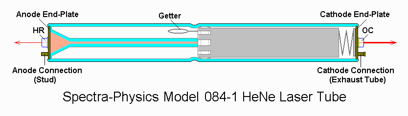
For a diagram with a little more artistic merit, see below:
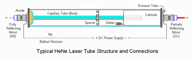
Typical He-Ne Laser Tube Structure and Connections
. And, for a diagram of a complete laser head:
Typical He-Ne Laser Head
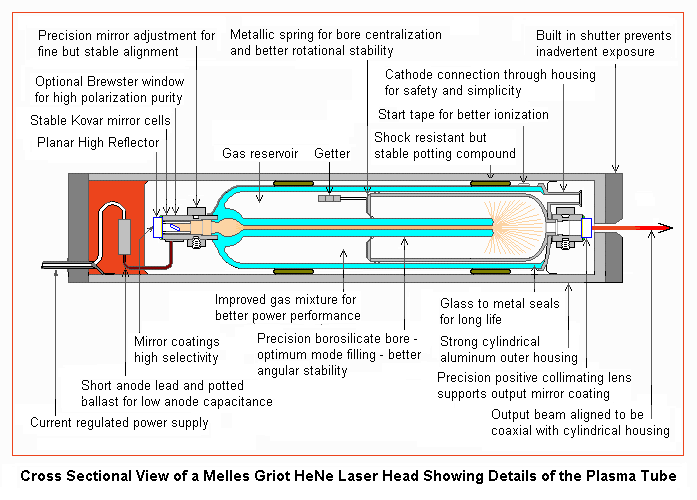
(Courtesy of Melles Griot) and actual structure below:
X-ray View of Melles Griot 05-LHR-911 He-Ne Laser Head
. For some photos, see below:
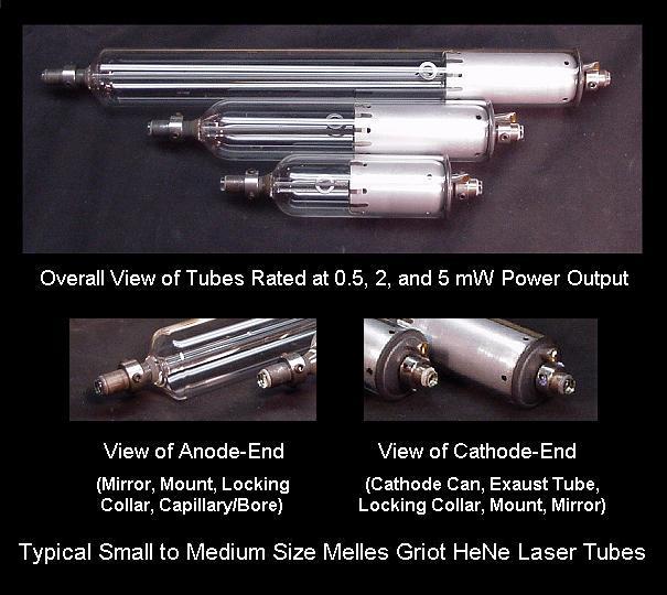
Typical Small to Medium Size Melles Griot He-Ne Laser Tubes
The ratings are guaranteed output power. These tubes may produce much more when new. Another type of construction that is relatively common is shown below
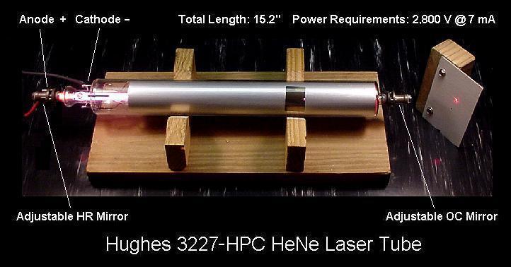
Hughes Style He-Ne Laser Tube
and a photo:
Hughes 3227-HPC He-Ne Laser Tube
These are probably disappearing though as Melles Griot bought the Hughes He-Ne laser operation and is converting most to their own design but many still show up on the surplus market, including newer ones with the Melles Griot label. Another design that is similar is below:
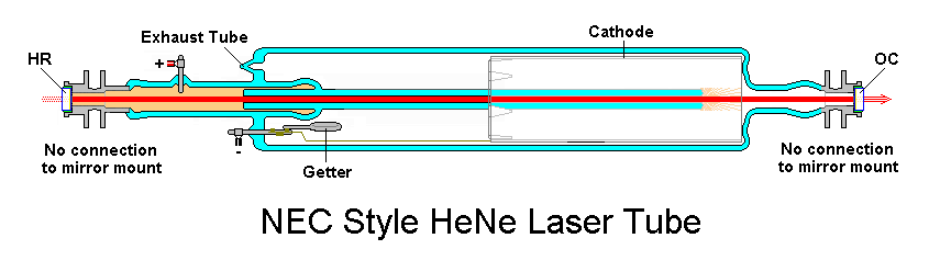
NEC Style He-Ne Laser Tube
Some specifications for various NEC He-Ne lasers can be found at SOC under “Gas Lasers”. Most common higher quality He-Ne tubes will be basically similar to one of these two designs though details may vary considerably. Most have an outer glass envelope but a few, notably some of those from PMS/REO, may be nearly all metal (probably Kovar but with an aluminium liner which is the actual cathode) with glasswork similar to that of Hughes or NEC at the anode-end.
Tubes up to at least 35 mW are similar in design but proportionally larger, require higher voltage and possibly slightly higher current. and of course, will be more expensive.
On most He-Ne laser tubes, the anode (+) end consists of a small cylindrical metal electrode with a mirror attached to it. However, on a few (usually Hughes-style), the anode may be a wire fused into the glass with the mirror mount separate from it.The discharge at this end produces little heat or damage due to sputtering.
On most He-Ne laser tubes, the cathode (-) end is also a cylindrical metal electrode with a mirror attached to it but in addition, there is a large cylindrical aluminium can in electrical contact and this is the actual cathode, extending a substantial fraction of the length of the tube. The main exceptions are Hughes-style He-Ne laser tubes where the cathode can is separate from the mirror mount at the cathode-end of the tube. CAUTION: Attaching the negative lead of the power supply to the mirror mount instead of the proper terminal will result in irreversible damage to the tube in a very short time.This is a ‘cold’ cathode – there is no need to heat it (like the ones in the electron guns of a CRT) for proper operation and no warmup period is required before the tube can be started. The discharge is distributed over the entire area of the can thereby spreading the heat and minimizing damage due to sputtering which results from positive ion bombardment. For this reason, although the laser may appear to work (in fact, starting tends to be easier) a He-Ne tube should not be run with reverse polarity for any length of time (e.g., more than a minute or so, preferably a lot less) since damage to the anode (now acting as a cathode) and its mirror would likely result. The can-shaped structure is also called a ‘hollow cathode’ for obvious physical reasons – it is a tube electrode that is large in diameter and hollow like a piece of pipe – and because the plasma discharge flows inside of it. It operates in the abnormal glow current density gas discharge region (should you care). The surface of the cathode can is also not pure aluminum as it appears, but is processed with a very thin layer of oxide which eventually gets depleted, and this is the main determination of tube life. Hollow cathodes are usually used where a tube needs lots of slow moving electrons to excite the gas. They are currently used mainly in HeNe lasers but have been applied to other types of gas lasers having modest current requirements.Very old He-Ne lasers (and some others, old and new, like argon ion) use a heated filament which also acts as the cathode instead of the cold cathode design. This structure can be much smaller than the cold cathode but the added complexities of manufacture, the additional power supply, and the need for a warm up period have dedicated it only to those applications where there is no other choice. A very few, very tiny He-Ne laser tubes, use a small ring-shaped cathode made of either zirconium (expensive) or aluminium. These were likely designed for special applications, presumably requiring very small size or fast turn-on response (due to the reduced capacitance). The examples of these He-Ne tubes I’ve seen are about 5″ long by 1/2″ in diameter. Life expectancy using the aluminium version (at least) is probably quite limited due to sputtering (since the electrode is very close to the bore, which promotes this due to the increased field gradient).
The major discharge is forced to take place inside a thick glass capillary tube with an inner bore of 0.5 to 1.5 mm depending on the power of the tube. This concentrates the discharge forcing operation in the most common and desirable TEM00 mode. Note that the appearance of the capillary viewed through the side is misleading due to the magnification of the thick glass – it is actually only about one half to two thirds as large as it looks!On some (mostly larger) He-Ne tubes, the bore may be ground (but not polished) on the outside, inside, or both:
Outside ground: The reason is quite simple and low-tech: The bore may be off to one side in the raw capillary enough to affect beam centering. So, it is centerless ground for precise fit in the bore support and there’s no added benefit to justify the cost of polishing it.
Inside ground: There are several possible reasons for this:
Beam quality – There is a statistically significant reduction in diffraction rings (stray light) around the main beam with a frosted bore ID, though some designs are more susceptible to this than others. However, sometimes requirements for a particular spot size or output power limit options and the frosting will help.
Off axis stimulated emission suppression – A rough interior minimizes reflections from the bore walls which steal power from the beam along the axis. This is particularly true of the 3.391 µm IR transition and may partially account for the lack of magnets (to suppress this line) on modern high power He-Ne lasers.
Promote return to the ground state – The added surface area may speed up depopulation of the energy state reached after stimulated emission by increased collisions with the tube walls.
Note that since the frosting process is done chemically (hydrofluoric acid etch?), the bore will become marginally wider and care must be taken that this doesn’t result in multimode (non-TEM00) operation if it goes too far!
Some older He-Ne lasers were built with a tapered bore – one that was wider at one end than the other. I’ve seen this in the circa 1970s Hughes 3184H as well as in a Melles Griot 05-LHP-170 tube of modern design (but serial number 675P – sounds kind of old!). The rationale is to match the bore to the lasing mode volume. So, if the resonator is near-hemispherical with a narrow intracavity beam at the flat mirror and a wider one at the curved mirror, the bore would be designed to more-or-less follow that profile to optimize gain. This was apparently all the rage early in the history of He-Ne lasers but has fallen out of favour because (1) it never did provide that much benefit and (2) manufacturing a tapered bore is much more expensive.
There have been some experimental He-Ne lasers built with an elliptical or rectangular bore to get around the limits on power imposed by small bore tubes. (Normally, gain is inversely proportional to bore size so just using a large bore doesn’t work.) Apparently, such lasers have generated over 300 mW with a highly multiple transverse mode beam in a package the size of a PC tower but were never developed commercially.One recent paper on such a laser is: “High power He-Ne laser with flat discharge tube”, Yi-Ming Ling, Journal of Physics D: Applied Physics, Volume 39, Issue 9, pp. 1781-1785, May, 2006.
Abstract:”A high-power He-Ne laser with a flat discharge tube has been realized. Its output power can be enhanced by increasing the transverse size of the discharge tube. This high-power flat He-Ne laser tube of 1.4m discharge length can achieve above 180 mW of output power at a wavelength of 632.8 nm. Its optimum discharge parameters and the gain characteristics are investigated experimentally. The experiments indicate that the optimum current increases with decreasing total gas pressure. But the increase in the optimum current is almost independent of the gas mixture ratio. The increase in the gain coefficient at the axis of the discharge tube with discharge current is not obvious. The boost in laser output power is mainly caused by the expansion of the lasing gain region. To achieve the higher output power, four of the laser tubes mentioned above are placed into one laser box. The laser beams are coupled into a quartz optic fibre and the output power from the end of the optic fibre can reach above 480 mW. This high-power He-Ne laser has been used in a clinical application, photodynamic therapy (PDT) of cancer, and its effective rate is above 90% in 183 clinical cases. The structure, characteristics and applications of this high-power flat He-Ne laser are introduced and discussed in this paper.”
Wow! 480 mW at 633 nm (even if it is an ugly beam)! 🙂
An outer glass envelope of much larger diameter than the capillary provides a substantial gas reservoir. While the helium-neon gas mixture doesn’t get used up, some unavoidable adsorption (sticking of the gas molecules to the glass and metal parts), gas being buried under sputtered metal, and leakage does occur. Having a larger gas supply minimizes any effects on performance.
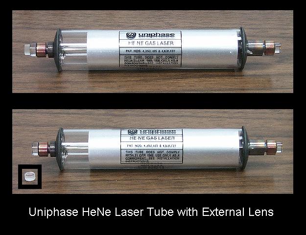
He-Ne tubes used in barcode scanners tend to use a simpler (possibly cheaper) design. Some typical examples below:
A typical small barcode scanner tube is shown below:
Uniphase He-Ne Laser Tube with External Lens
. That negative lens is used in the barcode application to expand the beam at a faster rate than with the bare tube. A second positive lens about 4 inches away is then used to recollimate the beam. (In many cases, the required curvature is built into the output mirror but not here. The lens was removed by soaking the end of the tube in acetone overnight.)
CAUTION: While most modern He-Ne tubes use the mirror mounts for the high voltage connections, there are exceptions and older tubes may have unusual arrangements where the anode is just a wire fused into the glass and/or the cathode has a terminal separate from the mirror mount at that end of the tube. Miswiring can result in tube damage even if the laser appears to work normally.
Gas Fill and Getter
In order for an He-Ne laser to operate efficiently (as such things go) or at all, there must be a very precise and pure mixture of helium and neon gas in the tube. The total amount of gas in a typical 1 mW He-Ne tube is much less than 1 cubic cm if it were measured at normal atmospheric pressure. It fills the tube only because the pressure is very low. However, with this small amount of gas, it doesn’t take much contamination or leakage to ruin the tube.
The gas fill consists of a mixture of helium and neon in the proportions of about 7:1 (He:Ne) at a pressure of 1.5 to 5 Torr (millimeters of mercury – 1 Torr is approximately 1/760th of standard atmospheric pressure). Note the large amount of helium even though it is the neon that actually emits the coherent light.
Some He-Ne tubes will have a ring or rectangular shaped metal structure (probably attached to the cathode) holding a spongy substance in its U-shaped cross-section, or it may just be a piece of metal coated on its outer surface. This is called the ‘getter electrode’. After the tube has been pumped down and sealed, it is heated by RF induction causing the spongy stuff to decompose and release a highly reactive metal like barium – the actual getter – which may be visible as a metallic or dark coloured spot on the glass near the getter electrode. However, some getter materials are perfectly transparent.The getter material is then available to chemically combine with residual oxygen and other unwanted gas molecules that may result from imperfect vacuum pumps and contamination on the tube’s glass and metal structures (e.g., from the surface as well as in fine cracks and other nooks and crannies). It will also mop up any intruder molecules that may diffuse or leak through the walls of the tube during its life. Helium and neon are noble gases – they ignore the getter and the getter ignores them. :-)Should the getter spot (if visible) turn to a milky white or red powdery appearance, it is exhausted and the tube is probably no longer functional.If you had grown up during the vacuum tube age, the getter would be familiar to you since nearly all radio and TV tubes had very visible silvery getters (and CRTs still do).The getter electrode can be seen in photos:
Typical Small to Medium Size Melles Griot He-Ne Laser Tubes
However, no getter spots are visible. I have found many tubes where there is a getter electrode present but the getter spot is undetectable. Some modern getters use a zirconium based material which is colourless as opposed to old style getters which were barium based with a very visible spot. (Really long life He-Ne tubes like those from Hewlett-Packard actually use a zirconium cathode. They are rated for a 100,000 hour life!) It’s also possible that the getter was included as insurance and never activated. I suppose that modern vacuum systems and processing methods are so good and hard-seal tubes don’t really leak, so there is not as much need for a getter as there used to be.
Note that a high mileage He-Ne (or other gas discharge) tube may exhibit metallic deposits (usually) near electrodes which look similar to the getter spot. However, these are due to sputtering and won’t change appearance if there is a leak! The tube is usually near death at this point in any case.
Mirrors in Sealed He-Ne Tubes
The mirrors used in lasers are a bit more sophisticated than your bathroom variety:
The mirrors are not silvered or aluminized (metal coated) but are a type called ‘dielectric’. They are made by depositing many alternating layers of hard but transparent materials having different indexes of refraction. The thickness of each is precisely 1/4 the wavelength of the laser light inside the material (632.8 nm being the most common for a He-Ne laser). This results in reflection by interference with very high (>99.9%) efficiency – much greater than for even the best metal coated mirrors. However, note that for a sufficiently long He-Ne tube (one with high enough gain), it would be possible to use a pair of freshly coated or protected aluminium mirrors though performance would be pretty terrible. And, getting a useful beam out of such a laser would be difficult because aluminized mirrors tend to not be even partially transparent! I’ve gotten a 10″ long He-Ne tube with an internal HR and Brewster window at the other end to lase using the aluminized mirror from a barcode scanner – just barely. But the first He-Ne laser would not have been possible without dielectric mirrors despite its length since the wide bore resulted in very low gain.
The mirrors may be perfectly flat (planar) or one or both may be spherical (concave with respect to the inside of the cavity) with a typical Radius of Curvature (RoC = 2 * the focal length) ranging from approximately the length of the cavity (L) to 2 or 3 times L. (Positive RoC means a concave mirror. Curved mirrors result in an easier to align more stable configuration but may be more expensive than planar mirrors to manufacture. A planar-planar narrow bore He-Ne laser would be virtually impossible to align and would change behaviour due to any unequal thermal expansion. Most or all of the tubes I’ve dissected have at least one curved mirror, usually with an RoC somewhat longer than the distance between the mirrors. Some will also have some ‘wedge’ (where the outer surface is angled slightly with respect to the beam axis to minimize instability resulting from reflections directly back into the resonator.I have also come across He-Ne laser output mirrors with a slight *negative* RoC – they are convex rather than concave with respect to inside the cavity. At first I thought these were a mistake, coating the wrong sides of the mirror glass or something like that. But the slightly convex curvature does indeed result in a stable resonator configuration and actually has a slightly lower divergence than a similar concave mirror when tested in my one-Brewster external mirror He-Ne laser (though I can’t tell if this might also have been more due to the curvature of the outer surface). I have since found a sample of a HeNe laser tube (probably from a barcode scanner) that had such a mirror, though it’s certainly not a common configuration.You may be able to tell which type you have by looking at a reflection off of the inner surfaces of the mirrors at each end (assuming the one at the non-output end is not painted or covered). Assuming the outer surfaces are flat, a concave mirror will reduce the size of the reflection very slightly compared to a planar mirror. If wedge is present, the reflections from the front and back (interior) surface of the mirror will shift apart as you move further away (though this may be tough to see on the Anti Reflection (AR) coated output mirror since the reflection from the AR coated surface will be very weak). To further complicate matters, the front (outer) surface of the mirror at the output-end of the tube may be ground to a (slight) convex or concave shape as well resulting in either a positive lens which aids in beam collimation or a negative lens with increases the divergence.
One of the mirrors will be nearly totally reflecting and the other will only be partially reflecting at the laser wavelength. These are called the High Reflector (HR) and Output Coupler (OC) respectively. Note that the HR isn’t perfect – there will be a low intensity beam exiting from that end of the tube as well as from the OC end assuming it is not covered with paint or tape.Since the reflection peaks at a single wavelength, this type of mirror actually appears quite transparent to other wavelengths of light. For example, for common He-Ne laser tubes, the mirrors transmit blue light quite readily and appear blue when looking down the bore of an UNPOWERED (!!) tube. Blue light from the electrical discharge will also pass out of the mirrors as a diffuse glow when running. No, you don’t have a blue He-Ne laser!
The OC mirror will have an Anti-Reflection (AR) coating for the lasing wavelength. With red (632.8 nm) He-Ne lasers, this will usually have a blue or purple appearance. The HR mirror in most tubes is polished flat with no AR coating, but occasionally will be painted over or covered with opaque tape. Higher quality tubes will have the HR glass slightly “wedged” to avoid a reflection from its outer surface going back into the tube and affecting lasing. (This can be detected easily by the presence of a very weak ghost beam at a slight angle to the already weak waste beam.) However, the HR mirror on some tubes may be fine ground or frosted.
The mirrors usually don’t have any ‘user’ adjustments. However, the cylindrical mirror mount stems are almost always mounted by thinner sections of metal tubing (usually a gap in the cylinder but sometimes between the stem and end-cap) so slight changes to alignment may be possible with appropriate fixtures. I do not recommend this without special precautions because:
Grabbing the high voltage electrodes is not likely to be pleasant and dropping the tube doesn’t do it any good.
The most likely result of a random attempt at alignment will be total loss of lasing.
It is too easy to break the seal if you get carried away after (2).
There should be no reason for the alignment to have changed unless you whacked the tube – it was set at the factory. But due to the way some tubes are constructed, it can creep with multiple thermal cycles over the years. If you suspect an alignment problem, it is easy to check. Then, you can decide if attempting an adjustment is worth the risks.
However, long high power tubes (i.e., 20mW and up) may require fixtures to maintain mirror alignment even when the mirrors are internal. For example, they may need to be securely mounted in their mating laser head cylinders. Such tubes will not be stable by themselves because thermal expansion will result in enough change in alignment to significantly alter beam power – even to the extent of extinguishing the beam entirely at times! There may even be a ‘This Side Up’ indication (not related to the orientation for linearly polarized tubes) on the He-Ne tube or laser head as gravity affects this as well (the alignment and thus power, not the gas, electrons, ions, or light!) and can significantly affect operation. I do not know if this latter sort of behaviour is common or only likely with tubes that are marginal in some way. But, there will always be at least a small change in power with orientation for longer tubes.
The main beam will emerge from the partially reflecting mirror but this may be at either end of the tube depending on model. For example, where the tube is enclosed in a metal barrel, the HV connections will be to the anode end and the beam will exit from the cathode end. With this arrangement, the positive output of the power supply and ballast resistor can be very close to the tube anode. The entire barrel (cathode) can be connected to earth ground for safety.There is a slight benefit to having the output coupler mirror at the anode-end of the tube due to the typical long-radius hemispherical cavity configuration. With the bore running almost to the mirror mount, more of the mode volume is inside the bore and thus the gain will be slightly higher. But the difference is only really significant for “other colour” He-Ne laser tubes which have very low gain and these are more likely to use anode-end output configuration.
Unlike common metal coated mirrors, these dielectric types are not perfectly reflective. Thus, there will be a weaker beam visible from the non-output end of the tube if that mirror is not covered (blocked or painted over). One use of this is to permit monitoring of laser power for purposes of optical power regulation or other closed loop applications.
Mirror Reflectances for Some Typical He-Ne Lasers
Here are some (approximate) typical OC reflectances for red (632.8 nm) He-Ne lasers determined by measuring the actual transmission (R = 100 – T) of a red He-Ne laser beam through the optic with a simple photodiode based laser power meter:
OC from 0.5 mW, 12.5 cm Melles Griot model 05-LHR-002-246 internal mirror He-Ne tube: 99.3 percent.
OC from 2.25 mW, 26 cm Spectra-Physics model 084-1 internal mirror He-Ne tube: 99 percent.
OC from 20 mW, 75 cm Aerotech model unknown internal mirror He-Ne tube: 97.7 percent.
OC from 50 mW, 177 cm Spectra-Physics model 125 large frame external mirror He-Ne laser: 99.4 percent.
The HRs in all cases showed greater than 99.9 percent reflectivity (T less than 0.001 – virtually undetectable on my fabulous meter).
Due to the behaviour of the photodiode at low light levels, the absolute precision of the readings is somewhat questionable. However, the relative reflectivities of these mirrors is probably reasonably accurate. Note, in particular, the high R of 99.4% for the very long external mirror laser compared to the low R of 97.7% (T of 2.3%) for a shorter internal mirror tube. I expect that in addition to the length of the bore, part of this difference is due to the absence of Brewster window losses in the internal mirror tube resulting in a higher gain so that more energy can be extracted via the OC on each pass.
Mirrors for non-red He-Ne lasers must be of even higher quality due to the lower gain on the other spectral lines. The OC will also have higher reflectivity for this reason. For green He-Ne tubes (which have the lowest gain of all the visible He-Ne wavelengths), the transmission is about 1/10th that of a similar length red tube. For example, the reflectivity of a typical green He-Ne tube OC is 99.92 to 99.95 percent (.08 to .05 percent transmission) at 543.5 nm.
Notes on making these measurements:
Position the sensor far enough from the laser that it doesn’t see a significant amount of bore light (incoherent glow from the discharge).
Block ambient illumination from falling on the sensor.
Orient the mirror being tested at a very slight angle so light doesn’t bounce back to the laser’s output mirror.
Assure that the sensor sees only the main beam and not any of its (possibly multiple) reflections from the mirror surfaces.
Take a reading with the sensor blocked (the ‘dark current’) and then subtract it from the actual measurements.
Average several readings of both the laser and transmitted power to minimize the error introduced due to power variations from mode cycling.
More About He-Ne Dielectric Mirrors
In the mid 1980s, before Ion Beam Sputtered (IBS) coatings really made their commercial debut, some mirrors were still Epoxied (soft-sealed), particularly those with a lot of coating layers (like 20 or 30), mostly green, yellow, and IR He-Ne lasers. These tubes need sharp cutoffs (to kill lasing on unwanted wavelengths) and/or ultra high reflectivity (due to their very low gain) in the coatings – which means a lot of layers. The packing density on Electron-Beam (E-Beam) coatings is not great, so water molecules get into all the layers. When you hard-seal the mirror by heating the frit, the water comes out and cracks the coating (called a ‘crazed’ mirror). Another problem with mega-stack E-Beam coatings is that the transmittance curve can shift as much as 10 nm (to longer wavelengths – the layers get thicker) during the oven cycle (again a water-thing). If you have to, say, highly reflect at 594.1 nm (for a yellow output tube) and highly transmit beyond 604.6 nm (to kill the orange and red), and your coating shifts 10 nm in the oven cycle, another batch of tubes ends up in the dumpster. 🙁 No! Send the my way. 🙂
Ion Beam Sputtered (IBS) coatings have a much higher packing density, so they withstand the (i.e., 450 °C) frit sealing temperatures and don’t even shift 1 nm. Nowadays, everything is hard sealed, with the exception of the high-end (long precision) Brewster tubes. Hard-sealing a BK-7 window puts a lot of stress on it, and that just isn’t acceptable on the high-Q tubes. So, those get fused silica windows optically contacted (lapped and polished surfaces that are vacuum tight.) (In fact, with this type of seal, if there is no adhesive present, the windows can be easily removed from your dead, leaky, or up-to-air tubes by heating the Brewster stem and window with a heat gun. The window can then be popped off with your thumbnail!)
Random and Linear Polarized He-Ne Tubes
Most common He-Ne laser tubes are randomly polarized since for many applications the polarization of the beam doesn’t matter. As noted elsewhere, the term “random” here really doesn’t mean that the polarization is necessarily jumping around to totally arbitrary orientations. In fact, such behaviour would be rather unusual, though lasers from some manufacturers do exhibit somewhat erratic mode flipping. It really just means that nothing special is done to control the polarization. The typical He-Ne laser will lase on several longitudinal modes (how many will depend on tube length of the resonator). For red (633 nm) He-Ne lasers, adjacent modes will generally have orthogonal to polarizations. Each of the modes will change their relative intensities periodically over time as the laser cavity changes length due to thermal expansion.
“Random polarized” is actually a poor choice of terminology since most random polarized He-Ne lasers do NOT exhibit random and/or high speed fluctuations in polarization. Rather there are generally two polarization axes that are orthogonal to each-other and the output power slowly varies between the two axes as the tube cavity length changes due to temperature and the lasing modes drift under the neon gain curve. (In fact, the tube used in a stabilized He-Ne laser must be a random polarized tube!). For most common tubes, the orientation of these polarization axes is determined by slight asymmetries in the tube geometry and/or mirror coatings (sometimes deliberate but most often simply as a result of manufacturing tolerances) and are fixed for the life of the tube. Lasers from Melles Griot, JDS Uniphase, and Siemens/LASOS generally have well behaved polarization. However, where there is virtually no asymmetry, the polarization axes could jump around, rotate, or perform some other acrobatics. 😉 Research Electro-Optics random polarized He-Ne lasers have somewhat unstable polarization behaviour due to (REO claims) their high quality ion beam sputtered mirror coatings which have virtually no asymmetry. Whether this is true, I can’t say. A Metrologic metal-ceramic tube was found to have unstable mode behaviour as well and its mirrors are probably nothing to write home about. However from a test using a Melles Griot plasma tube with two perpendicular windows in place of internal mirrors, the orientation of the external mirrors had no impact on the polarization axes and the modes were well behaved. Only the tube orientation mattered even though the intra-cavity mode volume was no where even near the capillary wall. I attribute this to very slight orientation preferences in the windows – when photons make hundreds of passes, even small anisotropies can be significant.
For the special case of a short tube where only two modes fit under the gain curve (typically 5 or 6 inches in length) at the instants when they are equal, the output will appear to be non-polarized (constant intensity as an external polarizer is rotated in the beam) but as the modes shift under the gain curve, one or the other polarization will dominate and for a portion of the entire cycle, the tube will be pure linearly polarized in each of these axes. For longer tubes, there will be much less of an effect because there will be multiple modes with both polarizations at all times.
The main physical effect resulting in a particular polarization direction being favoured in a random polarized He-Ne tube is a slight preferred axis in the dielectric mirror coatings or in subtle aspects of the geometry of the tube due to manufacturing tolerances. Where these effects are very small or cancel, the resulting polarization axes may indeed not be restricted to a fixed orientation, but this tends to be less common. Most often, the polarization axes are fixed for the life of the tube. It’s possible to design a tube with a known orientation for the polarization axes as REO has done for their stabilized He-Ne lasers, but this turns out to be more complex and expensive, so usually it’s left up to natural selection. 🙂
Most linearly polarized He-Ne laser tubes are similar to their randomly polarized cousins but include a Brewster plate or window inside the cavity which results in slightly higher gain for the desired polarization orientation. Such tubes produce a highly polarized beam with a typical ratio of 500:1 or more between the selected and orthogonal polarization. External mirror He-Ne lasers almost always use Brewster windows and so are inherently linearly polarized. A strong transverse magnetic field can also be used to force linear polarization and indeed, long before I observed this phenomenon, some commercial He-Ne lasers offered a “polarization option” which was a set of magnets to be placed next to the bore.
Another way to force linear polarization in a He-Ne laser (or any other low gain laser) is to add a mirror at 45 degrees reflecting to the actual HR mirror, which is then at 90 degrees to the optic axis (facing sideways). The 45 degree mirror will have a slight polarization preference (or can be designed that way) so its reflectance will be extremely high at the desired polarization and slightly lossy at the unwanted one. Like the Brewster plate, this is enough to force linear polarization in low gain lasers. The undesirable losses from the extra mirror bounce may be less than the losses through a less than perfect Brewster plate or one with a slight orientation error, which is particularly important for “other colour” He-Ne lasers, especially green, which has the lowest gain. However, this approach is much less common than using a Brewster plate (even for green). I’ve only seen it in PMS green He-Ne laser heads. Based on a test of the mirrors from a broken tube, the reflectance of the 45 degree mirror was about 99.997% for the preferred polarization orientation and 99.9% at the unwanted one. The 90 degree mirror had a reflectance of about 99.997% regardless of polarization. This difference in loss is far less than for a Brewster window but is still more than adequate for the green laser, though probably not for a higher gain red one. And the one PMS polarized yellow He-Ne laser head I’ve had used a Brewster plate. For more info, see: U.S. Patent #6,567,456: Method and Apparatus for Achieving Polarization in a Laser using a Dual-Mirror Mirror Mount.
Linearly polarized He-Ne lasers tended to be used in older laser printers (since the external modulator often required a polarized beam) and older LaserDisc players (because the servo and data recovery optics required a polarized beam). Randomly polarized lasers were used in older barcode scanners since polarization doesn’t matter there. Note the use of “older”. Nowadays, this equipment all use diode lasers which are inherently polarized. I’ve heard of people retrofitting such equipment to use diode lasers without much difficulty, but your mileage may vary. 🙂
More on Random Polarized He-Ne Lasers
As noted above, the term “random polarized” doesn’t mean that the polarization is necessarily jumping around at random, but rather that nothing special is done to control polarization. Only natural sources of light such as incandescent lamps produce anything approaching true random polarization since each of the emitters (e.g., atoms, etc.) is oscillating more or less independently of its neighbours in both polarization and wavelength (or frequency). Thus the resulting net polarization will be varying on a time scale of femtoseconds (10-15 seconds) and testing with a polarizer will simply show a uniformly non-polarized source – the intensity of the light that passes through the polarizer will be independent of its orientation.
However, the output of a laser consists of one or more “lasing lines” which correspond to those optical frequencies which match a cavity resonance (“cavity mode”) AND where the round trip net gain within the laser cavity is greater than one. These are the longitudinal (or axial) modes of the laser and each one will have a specific polarization and optical frequency. The cavity modes are spaced at a distance of f=c/2L (called the “Free Spectral Range” or FSR, where f is optical frequency, c is the speed of light, and L is the distance between the mirrors). For the typical He-Ne laser, there are between 1 or 2 (for a 15 cm 1 mW tube) and 10 or 12 (for a 1 meter 35 mW tube) present at any given time.
Mode Sweep of 8 mW Random Polarized He-Ne Laser
The image above illustrates this for a medium size laser.
For the red (632.8 nm) He-Ne laser, unless something specific is done to control the polarization inside the laser tube, adjacent longitudinal modes will usually be orthogonally polarized (the red and blue lines in the diagram, above). The orientation of their two axes will be determined by some very slight asymmetries in the tube’s construction or mirror coatings, and will usually remain fixed for the life of the tube. For reasons that are not clear, in Melles Griot tubes at least, one of the two axes often tends to line up approximately with the exhaust tip-off even though nothing special is done to make this happen and there is no obvious structural characteristic of the tube to cause it. The polarization axes can also be forced to be at a particular orientation, though some tubes using this technique may have other quirks. Melles Griot, JDS Uniphase, and Siemens/LASOS tubes usually (but not always) have well behaved polarization. But symmetry is desirable in some tubes such as those found in HP/Agilent Zeeman-split lasers. These tubes are normally installed in an axial magnetic field and then they are extremely well behaved. But without the magnet, the polarization, while not exactly totally random, does behave rather strangely. And REO claims their mirrors are so good and symmetric that they have problems with polarization and had to implement an more complex scheme to force the polarization axes to be have a fixed orientation for their stabilized He-Ne lasers.
Should the temperature of the laser cavity change, the distance between the mirrors increases or decreases resulting in a shift in the position of the cavity modes. For most He-Ne lasers, this happens inadvertently as a result of the heating caused by the bore discharge during warmup. But it can also be caused by changes in ambient temperature as well as heating or cooling intentionally applied, usually for the purposes of laser stabilization. For the most common situation, as the tube warms up and the cavity expands, longitudinal modes will drift through the neon gain curve, disappearing at one end (longer wavelength, lower optical frequency) as the gain falls below the lasing threshold, and being replaced at the other end (shorter wavelength, higher optical frequency) as the gain there rises above the lasing threshold. The total output power in each of the two polarization axes will correspond to the sum of the power in its lasing modes. The total output power of the laser is the sum of the output power in both polarizations. In most real He-Ne lasers, the variation versus time as the tube warms up – called “mode sweep” or “mode cycling” – is smooth and occurs on a time scale of seconds to hours depending on how close the tube is to thermal equilibrium, being fastest just after the laser is turned on. The modes are not jumping around on a time scale of nanoseconds as has been suggested by at least one major supplier of He-Ne lasers! 🙂 However, depending on the size of the laser, there can be high frequency variations in power in each polarization, or in a combination of the two observed with a high speed photodetector and oscilloscope. More on this below.
There are several specific cases depending on the length of the laser cavity. To simplify the explanation, it is assumed that the laser tube has been rotated in its mounts so that the natural polarization axes are at 0 and 90 degrees. In addition, the second order ripple and noise in the output from imperfect power supplies or other external factors are assumed to be small (which is typically the case). Also, fine points like mode pulling (which shift the modes very slightly in position, a small fraction of 1 percent) are ignored. So, the FSR (Free Spectral Range or cavity mode spacing) is equal to the longitudinal (or axial) mode spacing of the lasing lines. And the lasers are assumed to be well behaved and not be “flippers” or “stutterers” or have other pathologic disorders:
1 or 2 longitudinal modes are present simultaneously (typical 0.5 to 1 mW laser with a cavity length of 12 to 15 cm): During mode sweep, the output will smoothly go through the following sequence (and everything in between):
Pure linearly polarized at 0 degrees.
Non-polarized where the power in both axes is the same.
Pure linearly polarized at 90 degrees.
Non-polarized where the power in both axes is the same.
Pure linearly polarized at 0 degrees.
And so forth.
Here, the term “non-polarized” means that rotating a polarizer in the beam will result in no variation of optical power passing through it. But the beam in this case actually consists of the two CW longitudinal modes with orthogonal linear polarization, and equal and constant amplitude. (This is totally unlike a natural non-polarized light source whose output consists of a superposition of a nearly infinite number of independent emitters with arbitrary polarization.)
Note that the axis of polarization is NOT rotating – power is simply shifting back and forth between the two fixed orthogonal polarization axes.
If the output is passed through a polarizer oriented at 0 or 90 degrees, the optical power will be seen to vary smoothly from 0 to to approximately the rated power of the laser in a cycle lasting a few seconds to hours depending on how close the tube is to thermal equilibrium. Aside from this slow variation, the output will be CW with no high frequency oscillation or noise – a pure single optical frequency. However, if a polarizer is oriented at an angle other than 0 or 90 degrees, whenever both modes are present, a high speed photodiode and oscilloscope (or frequency counter or RF spectrum analyzer) would show a beat signal between the two lasing modes at a frequency equal to the longitudinal mode spacing (around 1 GHz for a short tube like this). If the polarizer is at 45 degrees, when both modes are equal in power, the beat would have a peak-to-peak amplitude of double the average power passing through the polarizer.
Longitudinal Modes of Typical Random Polarized 1 mW HeNe Laser
Above is a diagram for this size laser showing the relationship of the neon gain curve, cavity modes, and lasing modes. The Power Point show [download id=”5604″] demonstrates the effect of changing cavity length on the lasing modes. The longitudinal mode spacing and thus the beat frequency (if present) is 1.063 GHz in this example. Specifically note that at no time are more than 2 modes present and they are always orthogonally polarized. (In real life, the motion is continuous, but I didn’t have enough patience to generate an infinite sequence of slides!)
Plot of Mode Sweep of Typical 1 mW Random Polarized He-Ne Laser Tube
Above shows the appearance of mode sweep using a dual polarization detector for a typical 12 cm random polarized He-Ne laser tube. The red and blue plots are the optical power for the two polarization axes. The green plot is the total optical power. Each polarization has exactly 0 power for a approximately 1/3rd of each cycle. (The plot has it slightly raised above 0 so that the green total power curve can be distinguished from the top of the mode it’s sitting on, but it really would be almost precisely 0 in real life, limited mainly by the quality of the polarizer in front of each detector.)
2 or 3 longitudinal modes are present simultaneously (typical 2 to 3 mW laser with a cavity length of 20 to 25 cm): During mode sweep, the output will smoothly go from the case where 2 modes are oscillating to where 3 modes are oscillating and and repeat.During the time while only 2 modes are oscillating, the output through a polarizer oriented at 0 or 90 degrees will be varying slowly with no high frequencies present as with the shorter laser, above.During the time while 3 modes are oscillating, one of the axes will have 2 modes of the same polarization (but spaced by twice the distance between longitudinal modes) and the other will have only a single mode which is pure CW. For the axis with 2 modes, a polarizer will show a beat at one half the longitudinal modes spacing of the laser. For the axis with a single mode, there will be no beat. If the polarizer is oriented at 45 degrees (or any angle other than 0 or 90 degrees) there will always be a beat at a frequency equal to the longitudinal mode spacing, or one half of it, or both (1.5 GHz and 750 MHz). However, this does NOT mean the polarization is jumping around; only that the power is varying in each of the polarization axes or when combined with the polarizer due to the way the E/M waves add up.
Longitudinal Modes of Typical Random Polarized 3 mW HeNe Laser
Above is a diagram for this size laser showing the relationship of the neon gain curve, cavity modes, and lasing modes. [download id=”5602″] demonstrates the effect of changing cavity length on the lasing modes. Unlike the 1 mW laser, above, when a longitudinal mode of the 3 mW laser is near the center of the gain curve, there can be modes on both sides of it (3 modes total).
Plot of Mode Sweep of Typical 3 mW Random Polarized He-Ne Laser Tube
Above shows the appearance of mode sweep using a dual polarization detector for a typical 22.5 cm random polarized He-Ne laser tube. The red and blue plots are the optical power for the two polarization axes. The green plot is the total optical power.
For both of these cases, exactly two modes can be maintained by a feedback circuit with one on either side of the neon gain curve to implement a stabilized He-Ne laser. Under these conditions, both of the polarizations are pure single modes with a constant CW output. They are a very pure single optical frequency with ultra-long coherence length when one of them is selected with a polarizer.
4 or more longitudinal modes are present simultaneously (typical 5 mW or higher power laser with a cavity length of 30 cm or more): During mode sweep, the output will smoothly go from the case where n modes are oscillating to where n+1 modes are oscillating and repeat.Where 4 or more modes are oscillating, the output through a polarizer will show a beat at all times regardless of orientation since there are always at least 2 modes present even at 0 and 90 degrees.
Mode Sweep of 8 mW Random Polarized He-Ne Laser
is a diagram for a laser where 5 modes are present showing the relationship of the neon gain curve, cavity modes, and lasing modes. [download id=”5606″] demonstrates the effect of changing cavity length on the lasing modes. The longitudinal mode spacing and thus the beat frequency is 373 MHz in this example. Depending on the position with respect to the neon gain curve and orientation of a polarizer, the beat frequency will be at a combination of the longitudinal mode spacing (373 MHz), and 1/2, 1/3, 1/4, and 1/5 of it (186.50 MHz, 124.33 MHz, and 93.25 MHz, and 74.60 MHz, although the last one will not “appear” in the slide show due to the discrete frames skipping over a very small region where 6 modes are present).
Plot of Melles Griot 05-LHR-151 He-Ne Laser Head During Warmup (Polarized)
Above shows the appearance of mode sweep using a dual polarization detector for a typical 325 mm random polarized He-Ne laser tube. The red and blue plots are the optical power for the two polarization axes. Since multiple longitudinal modes are present at all times, the power variation in each polarization axis is small and the variation in total power is even smaller. As the length of the laser is increased, these power variations become still smaller.
For extremely low power tubes with a cavity length less than 8 or 9 cm, there will never be more than 1 lasing mode present at any time and during a portion of the mode sweep, there may be exactly 0 modes and no beam at all. There will never be any beat frequency detectable in the output. Since two adjacent modes are needed to force orthogonal polarizations and that never occurs, these tubes may lase with the same polarization each time the single mode appears, or the polarization may come up randomly one way or the other (but will remain the same while it’s present). So perhaps, such tubes can be truly called random polarized. 🙂 However, they are now almost non-existent.
Finally, for most linearly polarized He-Ne lasers, a Brewster plate or Brewster window(s) within the laser cavity provide enough gain asymmetry to force the polarization to be in one plane only. The polarization purity is usually very high – 500:1 or more. Everything above about mode sweep still applies except that all the longitudinal modes have the same polarization. So the diagrams, Power Power shows, and plots will look identical except that all the modes would be the same colour. 🙂 A polarizer will not affect the relative amplitude of the modes, only the intensity and angle of the linearly polarized beam. And whenever more than 1 longitudinal mode is present, there will be a beat signal detectable using a fast photodiode which will contain one or more frequencies depending on the possible distances between all the lasing modes.
So what this all shows is that random is all in the eyes of the polarized beholder. 🙂
More on Mode Cycling in Short He-Ne Lasers
As noted, a randomly polarized He-Ne laser doesn’t really produce arbitrary polarization but the individual longitudinal modes may switch polarizations as the tube warms up and expands. Where the distance between the mirrors is small – 5 or 6 inches as is the case with small He-Ne laser tubes, only two adjacent modes will fit under the inhomogeneously Doppler-broadened gain curve of neon. With only two active modes, effects of mode changes may be obvious even without anything more than Mark-I eyeballs and a polarizing filter but fancy equipment may be needed to fully characterize what’s going on.
Our testing suggested that adjacent modes always have orthogonal polarization – (lets go with S and P designations). BUT, in some two-mode tubes, a given mode doesn’t always REMAIN S or P as it changes in frequency (it flips polarization). In “flippers”, certain frequencies only support one polarization. If this frequency range is around the centre of the gain curve, most power will be of one polarization regardless of temperature (so it appears to be linearly polarized). (However, the extinction ratio varies over time, and is generally poor).
Here’s a test setup that shows what’s going on if you have access to some nice instrumentation: Send the beam from a two mode, randomly polarized He-Ne tube (Example: 05-LHR-006) into a Scanning Fabry-Perot Interferometer. (SFPIs are generally exorbitantly priced, but you can build one if so inclined. Put a polarizer in the beam path, aligned to maximize P polarization (or S polarization, doesn’t matter). Normally, the P mode will remain P polarization at all frequencies under the gain curve. So as the frequency changes (due to cavity length changes with temperature), the P mode will trace out a nice pretty sort of bell-shaped curve with a width of about 1.6 GHz FWHM. Bottom line, you can get P-polarized light at every frequency under the gain curve.
In a ‘flipper’, your curve has missing sections. In other words, there are some frequencies where you cannot get P polarization. When the observed, P mode reaches one of these frequency ranges, it will flip and become S-polarized. When the flip occurs, the other, formerly S mode, turns into a P. If you’re just looking at one polarization (as the experiment describes), the observed P mode disappears and pops up again at a frequency delta equal to the longitudinal mode spacing (where the S mode used to be). Some call it mode hop, but it really isn’t, because both modes are still there. Both modes still have, and always had, orthogonal polarization – they just swapped. Some tubes flip at one point under the gain curve, some flip many times under the gain curve.
This has to do with gain asymmetry. What brought it to our attention, is that when the polarizations flip, you get high frequency ‘noise’ if you have polarization sensitive components in your beam path. Solutions are to specify a laser that doesn’t flip, go to a three mode (longer) laser, go to non-polarization sensitive optics all the way through the beam delivery/detection train, or put a bandwidth filter on your detector.
A magnetic field will sometimes make a flipper stop, and sometimes make a non-flipper start – but not always. Sans magnetic field, over time (several thousand operating hours) our test population suggested that flippers always flip, non-flippers always behave.
There is more on flippers below.
He-Ne Mode Flipper Observations
The longitudinal modes of a He-Ne laser tube sweep through the gain curve as the resonator heats and expands. On a random polarized red (632.8 nm) tube, adjacent modes tend to be orthogonally polarized due to non-linear mode competition (or something). With well behaved tubes, once a mode starts lasing with a given polarization as it exceeds threshold on one side of the gain curve, that polarization is fixed until the mode ceases lasing on the other side of the gain curve. The Power Point show [download id=”5602″] demonstrates the effect of changing cavity length on the lasing modes in a well behaved 2 to 3 mW random polarized tube.
A “flipper” tube is one where the polarization orientation of adjacent longitudinal modes swap places at a fixed location on the neon gain curve as the modes sweep through it. Some will flip at multiple locations on the gain curve but this is less common. The Power Point show [download id=”5608″] demonstrates the effect of changing cavity length on the lasing modes in a classic 2 to 3 mW flipper tube.
The issue of why some tubes are flippers is apparently one of those grand mysteries of the Universe that even the Ph.D. types at major laser companies have been pondering for eons without resolution, as it’s still not always possible to manufacture a tube that is guaranteed to be well behaved. 🙂 Flipper behaviour may not be detected where the laser is simply used as a source of photons for the same reason that polarization effects of normal mode sweep tend to be minimal since the total power doesn’t vary that much. However, polarization flips will introduce short noise spikes. And if there are any polarization sensitive optical elements (intentional or not), significant sudden power fluctuations will also be evident in the polarized beam(s).
As with random polarized HeNe lasers not being random at all, flipper behaviour is also mostly deterministic in that for a given tube, flipping will usually always occur at the same place(s) in the mode sweep, but there are exceptions.
Plot of Melles Griot 05-LHR-640 He-Ne Laser Tube During Warmup (Polarized)
Above is of a normal short He-Ne laser tube showing the two polarized modes. Note that the amplitude of each one varies smoothly with no discontinuities.
Plot of “Flipper” Aerotech OEM1R He-Ne Laser Head During First Part of Warmup
Above is a closeup of the mode cycles for a classic case of flipperitis. Note the perfectly vertical edges on the red and blue plots. Based on laser theory, the flips probably require 100s of nanoseconds, but as a practical matter, they are instantaneous.
Plot of “Flipper” Aerotech OEM1R He-Ne Laser Head During First Part of Warmup (Combined)
Above is the same location but with the two plots superimposed. Ignoring colour (red or blue) and tracing the continuous lines would result in the normal mode cycling behaviour. And this tube is peculiar in that it eventually reverts to normal behaviour once close to thermal equilibrium as shown below:
Plot of “Flipper” Aerotech OEM1R He-Ne Laser Head at Transition to Normal Behaviour (Combined)
And this sequence from flipper to normal is totally repeatable if the laser is turned off and allowed to cool down and then turned back on.
Mode Sweep of Melles Griot 05-LHR-038 “Flipper” He-Ne Laser Tube
Above shows another classic case of flipperitis but where the laser always flips so the plot has pretty much the same appearance all the time except for the length of the mode sweep cycles. There are some tiny blips just before the flip and at two other locations during the mode sweep cycle but these do not result in flips. Such blips are generally not present in well behaved lasers unless they are thinking about being naughty. 🙂
Mode Sweep of Melles Griot 05-LHR-121 “Flipper” He-Ne Laser Head
Above shows yet another example where the laser always flips. Note that something really peculiar is occurring just before the flip occurs. Apparently, it’s attempting to maintain the normal shape with the double bump but cannot and then flips. Compare this to the expected shape of the modes which is shown below:
Mode Sweep of Melles Griot 05-LHR-120 He-Ne Laser Tube
for a physically identical normal bare tube. (Whether a head or tube is irrelevant.). Small bumps and dips are also evident at other locations but do not result in flips. The general shape of the normal mode sweep can be seen in the bad laser but it is distorted.
While I haven’t seen any discussion of flipper theory, here are some thoughts.
In the absence of external influences like magnetic fields, the mode orientation in a laser will be determined by at least two factors:
Resonator orientation preference: Since the modes in most random polarized He-Ne laser tubes will tend to be polarized at a fixed pair of orientations with respect to the physical tube (i.e., the exhaust tip-off), this implies some asymmetry in the construction which favours gain at these orientations. If a tube were perfectly symmetric, the modes could appear at arbitrary orientations but this is very rare. In most cases, they are fixed for the life of the tube.
Polarization birefringence: Many types of dielectric mirror coatings are not perfectly symmetric with a very slightly higher gain for light polarized at one specific orientation compared to that 90 degrees from it. A certain amount of asymmetry can be tolerated but if it becomes excessive, once the “wrong” polarized mode amplitude becomes large enough, its polarization flips. Since there are two mirrors, the relative orientation would be an important factor. If their birefringence axes were orthogonal, there would be no preference. If they were lined up, it would a maximum. Since no effort is made to orient the mirrors when they are attached to the tube, this could be a source of the behavioural differences between tubes.
Since a transverse magnetic field can also introduce a polarization preference, it is possible to cause a well behaved He-Ne laser tube to exhibit flipper behaviour by the careful placement of s strong magnet near the tube. I’ve demonstrated this with a normal Uniphase 098 laser. With no magnet, the mode sweep is perfectly ordinary with no tendency to flipping. By placing a single rare earth magnet next to the tube near the middle, it can be made to turn into a flipper with a mode plot very similar to that of a natural flipper. With too weak a magnetic field, there is no effect or a sort of shortened aborted flipping. With too strong a magnetic field, the polarization becomes locked to the magnetic field and the output ends up being linearly polarized.
For that peculiar tube above which reverts to normal behaviour at the very end of the warm-up period, a very weak magnetic field will cause it to continue to flip after the point of transition where flipping ceases under normal conditions.
Plot of “Flipper” Aerotech OEM1R He-Ne Laser Head with Various Magnetic Fields Applied (Combined)
Above shows the effect of a rare earth magnet at 4 orientations about 4 inches from the center of the laser head compared with no magnetic field. The magnetic field axis was horizontally aligned with one of the polarization axes of the laser. The magnet was rotated 90 degrees approximately every 30 seconds. The first and last orientation shows a mode sweep pattern that is relatively normal. They probably differ slightly because the magnet wasn’t in exactly the same position. The tube was allowed to completely warm up with the magnets in the last orientation with no significant change in the plot, even after the transition point where the tube reverts from flipper to normal behaviour with no magnetic field A closeup is shown below:
Plot of “Flipper” Aerotech OEM1R He-Ne Laser Head with Magnetic Field Induced Somewhat Normal Behaviour (Combined)
While very different than the mode plot of the tube after warm-up with no magnetic field, the flips are gone (no vertical jumps) and it’s relatively well behaved.
Conversely, it should be theoretically possible to suppress flipper behaviour with a suitably placed magnet. Getting this to work is more problematic since the magnetic field has to exactly counteract the natural polarization birefringence. But I was able to somewhat do this with my flipper head so that the mode sweep became well behaved. This was more finicky than going the other way. Almost any magnetic field did disrupt the normal flipper behaviour. But getting it to be really well behaved was more difficult.
Of course, a magnetic field will also introduce other effects due to Zeeman splitting which may be detrimental depending on the application.
Note that mirror alignment which may affect the resonator orientation preference had no effect on flipper behaviour, at least for the one sample I tested. Pressing on the mirror mount of my flipper tube in any direction would reduce the output power significantly due to changing mirror alignment. But the mode flips still occurred, and appeared to be at approximately the same location on the gain curve.
Some observations and questions:
One of the polarization axes tends to be aligned with tip-off in many tubes. Why? This isn’t always the case but seems to occur more often than not and thus something more than random chance is going on. Is it some sort of stress introduced during pinch-off, or some phenomenon that is due to something during pump-out and bake?
Short barcode scanner tubes with 8mR divergence I tested were almost all flippers. It has been suggested that the non-flippers were selected for more critical applications but I kind of doubt this as such tubes are rarely used for things like stabilized lasers where this would be important. I would expect that it is more likely to be back-reflections from the highly curved outer surface of the output mirror but could it be some other aspect of their design?
Some model tubes are consistently well behaved. For example, I can’t recall ever seeing a Spectra-Physics 088 that was a flipper.
Will polarization axes remain with tube if it is rotated relative to the mirrors?
Will the relative orientation of the mirrors affect polarization or flipping if one is rotated with respect to the other?
Speculation:
No asymmetry: Polarization can be at any orientation at random. Very rarely, if ever seen with He-Ne lasers.
Small assymetry: Normal case. Polarization will always be at fixed orientation and 90 degrees to it. Alternating modes will have orthogonal polarization.
Moderate asymmetry: Flipper. Mirror or tube will slightly favor one polarization orientation. When a mode starts with orthogonal polarization, it will progress until the lower energy state is one where the polarization flips.This state can be forced from (2) by a small transverse magnetic field.
Large asymmetry: Polarized tube, Brewster plate.This state can be forced from (2) or (3) by a large transverse magnetic field.
I now have been able to borrow a dual perpendicular window HeNe (gain) tube and was hoping to shed light (no pun…) on some of these issues by constructing a setup similar to the one described in the section: Transverse Zeeman Laser Testbed 1. This enabled the tube or one of the mirrors to be rotated without affecting alignment. The tube is longer than I’d like – about 14 inches resulting in a mirror spacing of about 16 inches – so it was necessary to really kill the gain with low reflectance mirrors and/or an aperture to get only 2 or 3 modes oscillating. But it should have been adequate to answer some of these questions. However, the somewhat unexpected result turned out to be that the polarization always remained with the tube regardless of mirror orientation even if the intracavity beam was much smaller than the bore so that any imperfections in its shape should not have had any effect. I attribute this to a very small amount of asymmetry in the transmission through the perpendicular windows. It might be AR coating or stress birefringence, distortion, or even the windows not being mounted quite perfectly perpendicular. With the intracavity photons traversing the windows an average of perhaps 100 times, even a minuscule asymmetry would be amplified into something significant. So on to Plan B, putting everything inside the gas envelope and doing away with the perpendicular windows entirely. Unfortunately, implementation of Plan B is currently not a funded project. 🙁 🙂
Polarization of Longitudinal Modes in He-Ne Lasers
It is well known that adjacent longitudinal modes in red (632.8 nm) He-Ne lasers (at least) tend to be orthogonally polarized as discussed above. This is a weak coupling as a magnetic field, Brewster plate, or even some asymmetry in the cavity can affect it or kill it entirely. And some lasers will cause the polarization to suddenly flip as modes cycle through the gain curve. However, the majority of modern well designed red He-Ne lasers will exhibit this phenomenon.
This is not necessarily true of “other colour” He-Ne tubes. My informal tests suggest that in general it is *not*. Long green (543.5 nm), short and long yellow (594.1 nm), and medium length orange (611.9 nm) random polarized He-Ne laser heads all exhibited varying degrees of erratic behaviour with respect to polarization. Usually, modes when part of the way through the gain curve and then either flipped abruptly or oscillated between polarizations for a short time and then flipped. The long yellow head liked to have pairs of adjacent modes with the same polarization but exhibited the flipper behaviour as well. However, adding a modest strength magnet near the long green seemed to force it to behave with adjacent modes having orthogonal polarization. I have no idea if this is significant or the long green He-Ne was simply a cooperating sample.
But what is the underlying cause?
(From: A. E. Siegman (siegman@stanford.edu).)
The reason that He-Ne lasers can run – more accurately, like to run – in multiple axial modes is associated with inhomogeneous line broadening (See section 3.7, pp. 157-175 of my book) and “hole burning” effects (Section 12.2, pp. 462-465 and in more detail in Chapter 30) in the Doppler-broadened laser transitions commonly found in gas lasers (though not so strongly in CO2) and not in solid-state lasers.
The tendency for alternate modes to run in crossed polarizations is a bit more complex and has to do with the fact that most simple gas laser transitions actually have multiple upper and lower levels which are slightly split by small Zeeman splitting effects. Each transition is thus a superposition of several slightly shifted transitions between upper and lower Zeeman levels, with these individual transitions having different polarization selection rules (Section 3.3, pp. 135-142, including a very simple example in Fig. 3.7). All the modes basically share or compete for gain from all the transitions.
The analytical description of laser action then becomes a bit complex – each axial mode is trying to extract the most gain from all the sub-transitions, while doing its best to suppress all the other modes – but the bottom line is that each mode usually comes out best, or suffers the least competition with adjacent modes, if adjacent modes are orthogonally polarized.
There were a lot of complex papers on these phenomena in the early days of gas lasers; the laser systems studied were commonly referred to as “Zeeman lasers”. I have a note that says a paper by D. Lenstra in Phys. Reports, 1980, pp. 289-373 provides a lengthy and detailed report on Zeeman lasers. I didn’t attempt to cover this in my book because it gets too complex and lengthy and a bit too esoteric for available space and reader interest. The early (and good) book by Sargent, Scully and Lamb has a chapter on the subject. You’re probably aware that Hewlett Packard developed an in-house He-Ne laser short enough that it oscillated in just two such orthogonally polarized modes, and used (probably still uses) the two frequencies as the base frequencies for their precision metrology interferometer system for machine tools, aligning airliner and ship frames, and stuff like that.
(From: Sam.)
Indeed, HP has several models of two-frequency He-Ne lasers but the ones I’m familiar with actually use an external magnet to create Zeeman splitting. Rather than two longitudinal modes, a PZT or heater is used to adjust cavity length so that only a single mode is oscillating, which is split by the Zeeman effect. Then, the difference frequency (in the low MHz range) is used in the measurement system as a reference and possibly for stabilizing the (optical) frequency.
The Spectra-Physics model 117A frequency stabilized He-Ne laser is designed more like what you are describing – two modes, no magnets. A heater is used to adjust cavity length in a feedback loop using a pair of photo diodes to monitor the two orthogonal polarized modes. However, I would assume that based on its description, the desired operating conditions would be for it to run with a single mode (which it can with carefully controlled cavity length). The Coherent and Melles Griot stabilized He-Ne lasers are similar.
Power Requirements for He-Ne Lasers
Power for a He-Ne laser is provided by a special high voltage power supply (see the chapter: HeNe Laser Power Supplies and consists of two parts (these maximum values depend on tube size – a typical 1 to 10 mW tube is assumed):
Operating voltage of 1,000v to 3,000v DC at 3 to 8mA. Like most low current discharge tubes, the He-Ne laser is a negative resistance device. As the current *increases* through the tube, the voltage across the tube *decreases*. The incremental magnitude of the negative resistance also increases with decreasing current.
Starting voltage of 5 to 12 kV at almost no current.In the case of a He-Ne tube, the initial breakdown voltage is much greater than the sustaining voltage. The starting voltage may be provided by a separate circuit or be part of the main supply.Often, you may find a wire or conductive strip running from the anode or ballast resistor down to a loop around the tube in the vicinity of the cathode. (Or there may be a recommendation for this in a tube spec sheet.) This external wire loop is supposed to aid in starting (probably where a pulse type starter is involved). There may even be some statistical evidence suggesting a reduction in starting times. I wouldn’t expect there to be much, if any, benefit when using a modern power supply but it might help in marginal cases. But, running the high voltage along the body of the tube requires additional insulation and provides more opportunity for bad things to happen (like short circuits) and may represent an additional electric shock hazard. And, since the strip has some capacitance, operating stability may be impaired. I would probably just leave well enough alone if a starting strip is present and the laser operates without problems but wouldn’t install one when constructing a laser head from components.With every laser I’ve seen using one of these strips, it has either had virtually or totally no effect on starting OR has caused problems with leakage to the grounded cylinder after awhile. Cutting away the strip in the vicinity of the anode has cured erratic starting problems in the latter case and never resulted in a detectable increase in starting time.
With a constant voltage power supply, a series ballast resistor is essential to limit tube current to the proper value. A ballast resistor will still be required with a constant current or current limited supply to stabilize operation. The ballast resistor may be included as part of a laser head but will be external for most bare tubes. (The exceptions are larger Spectra-Physics He-Ne lasers where the ballast resistors are also inside a glass tube extension, electrically connected but sealed off from the main tube.In order for the discharge to be stable, the total of the effective power supply resistance, ballast resistance, and tube (negative) resistance must be greater than 0 ohms at the operating point. If this is not the case, the result will be a relaxation oscillator – a flashing or cycling laser!
Power supply polarity is important for He-Ne tubes. Electrical behaviour may be quite different if powered with incorrect polarity and tube damage (and very short life) will likely be the result from prolonged operation.
The positive output of the power supply is connected to a series ballast resistor and then to the anode (small) electrode of the He-Ne tube. This electrode may actually be part of the mirror assembly at that end of the tube or totally separate from it. The distance from the resistors to the electrode should be minimized – no more than 2 or 3 inches.
The negative output of the power supply is connected to the cathode (large can) electrode of the He-Ne tube. This electrode may be electrically connected to the mirror mount at that end of the tube but is a separate aluminium cylinder that extends for several inches down the tube. CAUTION: Some He-Ne tubes use a separate terminal for the cathode and sometimes the anode as well, not the mirror mount(s). Powering one of these via the mirror mounts may result in lasing but will also result in tube damage.
Note: He-Ne tube starting voltage is lower and operating voltage is higher when powered with reverse polarity. With some power supply designs, the tube may appear to work equally well or even better (since starting the discharge is easier) when hooked up incorrectly. However, this is damaging to the anode electrode of the tube (and may result in more stress on the power supply as well due to the higher operating voltage) and must be avoided (except possibly for a very short duration during testing).
Every He-Ne tube will have a nominal current rating. In addition to excessive heating and damage to the electrodes, current beyond this value does not increase laser beam intensity. In fact, optical output actually decreases (probably because too high a percentage of the helium/neon atoms are in the excited state). You can easily and safely demonstrate this behaviour if your power supply has a current adjustment or you run an unregulated supply using a Variac. While the brightness of the discharge inside the tube will increase with increasing current, the actual intensity of the laser beam will max out and then eventually decrease with increasing current. (This is also an easy way of determining optimal tube current if you have not data on the tube – adjust the ballast resistor or power supply for maximum optical output and set it so that the current is at the lower end of the range over which the beam intensity is approximately constant.) Optical noise in the output will also increase with excessive current.
The efficiency of the typical He-Ne laser is pretty pathetic. For example, a 2 mW He-Ne tube powered by 1,400 V at 6 mA has an efficiency of less than 0.025%. More than 99.975% of the power is wasted in the form of heat and incoherent light (from the discharge)! This doesn’t even include the losses of the power supply and ballast resistor.
A few He-Ne lasers – usually larger or research types – have used a radio frequency (RF) generator – essentially a radio transmitter to excite the discharge. This was the case with the original He-Ne laser but is quite rare today given the design of internal mirror He-Ne tubes and the relative simplicity of the required DC power supply.
Operating Regions of a He-Ne Laser Tube
There are several distinct operating regions for a He-Ne plasma discharge as a function of tube current each of which has its own properties. The following summary is partially extracted from the He-Ne Laser Manual by Elden Peterson and is mostly just for curiosity sake as there is little reason to run a He-Ne laser tube at anything other than close to the nominal current (which results in maximum power output and rated life) listed in the tube specifications except possibly to implement low level modulation for laser communications. However, some manufacturers do run their tubes at lower current when maximum power isn’t needed, possibly to extend life.
Dropout: Below this current, no stable discharge is possible. While increasing ballast resistance (up to 150K to 200K) may reduce the dropout current somewhat, there will come a point where no amount of ballast resistance will be enough. The typical value will be 1/2 to 2/3 of the nominal operating current when the tube is new but this will be affected by the tube and wiring capacitance as well as the condition of tube (age if soft seal; how much it’s been used) and probably other factors. Running the laser at or below dropout will result in a relaxation oscillator which is hard on tubes and power supplies and should be avoided.
Plasma oscillation: Slightly above dropout current there may be a regime where there are oscillations in tube current and thus modulation of output power. Increasing the ballast resistance (cathode and/or anode) may eliminate this phenomenon.
Nominal: The output power will be maximum and the tube will run happily with the recommended ballast resistance. A few tenths of a mA on either side of nominal won’t cause any harm and only minimal reduction in output power (it’s a smooth maximum). Between dropout and nominal, output power will increase, but not in proportion to current and not linearly. The usable output power variation (e.g., for modulation purposes) is usually in the 15 to 25 percent range.Most healthy tubes will still produce a substantial fraction of their maximum output power even just above the dropout current. However, in rare instances (and probably with a large ballast resistor to push down the stable current as far as possible and/or where the tube low gain due to contamination or end-of-life), lasing will actually cease above the dropout current.
Single frequency noise: At a current level a mA or so above nominal, the plasma will begin to oscillate, generally at a few MHz. This will result in both an oscillation in output power (as high as 20 or 30 percent but generally just a few percent) as well as in the current itself.Between nominal and the onset of single frequency noise, output will decrease somewhat, but again not in proportion (or inverse proportion) to current. Attempting to modulate current symmetrically around the nominal current will result in a sort of rectification or absolute value effect on the variation in output power.
Broadband noise: Raising the current still further will result in the generation of broadband optical noise which is quite disorganized and random like white noise.
Cessation of output: Raising the current even further will result in a total loss of optical output at the lasing wavelength. The only light will be from the very bright plasma discharge. This point is typically reached at a current of 2 to 3 times nominal. It’s interesting to try the experiment – your laser will be happy again once the current is reduced assuming it hasn’t been left in this state for too long. However allowing the tube cook at these currents will shorten its life (and possibly that of your power supply as well) but what will probably die first (and quite quickly) is the ballast resistance unless its power dissipation rating is much higher than required at the nominal current! And if the power supply and ballast resistors don’t die, the tube may crack. In any case, extended operation at these excessive currents should be avoided.
Note that the visual effect of increasing current from dropout to cessation of output will just be a smooth increase and then decrease in coherent optical output power. To detect the single frequency or broadband noise will require a sensor and oscilloscope with a bandwidth of at least a few MHz.
I’ve also seen lasers where single frequency noise occurred close to the dropout current and below the point of maximum output power. However, this was only present with some high mileage tubes in HP-5517 lasers so it’s not clear whether this should be listed as a separate regime, or just a special case of a particular tube and power supply combination.
Also of note is that the He-Ne laser power supply itself will contribute to optical ripple and noise. A DC input switchmode (inverter) power supply will have ripple at the switching frequency. This is typically in the range of 1 to 5 percent of the operating current and will result in an optical power variation of a few tenths of a percent. An AC input linear power supply will have some ripple at 1X or 2X of the line frequency (with some harmonics) even with a regulator. An AC input switcher (most bricks) will have both types of ripple. Special low noise power supplies are available for critical applications. However, for most common uses, the additional cost is not justified.
He-Ne Tube Dimensions, Drive, and Power Output
A large number of factors interact to determine the design of a modern He-Ne laser. Beam/bore diameter, bore length, gas fill pressure, voltage, current, and mirror design, are all critical in determining how much output power will be produced – or whether a given tube will lase at all. Hundreds (at least) of technical papers and entire phone book size volumes filled with equations have no doubt been written on these topics and we can’t hope to do anything serious in a few paragraphs, but at least, may be able to give you a feel for some of the relationships among power output, bore dimensions, gas pressure, and drive requirements in particular.
You have probably wondered why the beam from a typical He-Ne laser (without additional optics) is so narrow. Is it that making a tube with larger mirrors would be more costly?
No, it’s not cost. Even high quality and very expensive lab lasers still have narrow bores. The very first He-Ne lasers did use something like a 1 cm bore but their efficiency was even more mediocre than modern ones. A wide bore tube would actually be cheaper to manufacture than one requiring a super straight narrow capillary. However, it wouldn’t work too well.
A combination of the current density needed in the bore, optimal gas pressure, gain/unit length in the bore, the bore wall itself aiding in the depopulation of lower energy states, and the desire for a TEM00 (single transverse mode) beam (there are multimode tubes that have slightly wider bores), all interact in the selection of bore diameter.
In fact, there is a mathematical relationship between bore size, gas pressure, and tube current resulting in maximum power output and long life.
The optimal pressure at which stimulated emission occurs in a He-Ne laser is inversely proportional to bore diameter. According the one source (Scientific American, in their Amateur Scientist article on the home-built He-Ne laser), the pressure in Torr is equal to 3.6 divided by the ID of the bore. I don’t know whether this exact number applies to modern internal mirror tubes but it will likely be similar. Power output decreases on either side of the optimal pressure but a laser with a low loss resonator may still produce some output above twice and below half this value.
Thus, as the bore diameter is increased, the optimal pressure drops. Aside from having fewer atoms to contribute to lasing resulting in a decrease in gain, below a pressure of about .5 to 1 Torr, the electrons can acquire sufficient energy (large mean-free-path?) to cause excessive sputtering at the electrodes. This will bury gas atoms under the sputtered metal (which may also coat the mirrors) leading to a runaway condition of further decreasing pressure, more sputtering, etc. Even with the large gas reservoir of your typical He-Ne tube (which IS the main purpose of all that extra volume), there may still be some loss over time. A drop in gas pressure after many hours of operation is one mechanism that results in a reduction in output power and eventual failure of He-Ne tubes.
As a result, the maximum bore diameter you will see in a commercial He-Ne laser will likely be about 2 mm ID (for those multimode tubes mentioned above where the objective is higher power in a short tube). Most are in the 0.5 to 1.2 mm range. This results in high enough pressure to minimize sputtering, maximize life, provide maximum power output, and optimal efficiency (to the extent that this can be discussed with respect to He-Ne lasers! Well, ion lasers are even worse in the efficiency department so one shouldn’t complain too much. Since total resonator gain is proportional to bore length and approximately inversely proportional to bore diameter (since the optimal pressure increases resulting in a higher density of lasing atoms), this favours tubes with long narrow bores. But these are difficult to construct and maintain in alignment. Wide bore tubes have lower gain but a higher total number of atoms participating with potentially higher power output at the optimal pressure and current density. Everything is a tradeoff!
However, all this does provide a way of estimating the power output and drive requirements of a He-Ne tube or at least comparing tubes based on dimensions. Assuming a tube with a particular bore length (L) is filled to the optimum pressure for its bore diameter (D), power output will be roughly proportional to D * L, discharge voltage will be roughly proportional to L (probably minus a constant to account for the cathode work function), and discharge current will be roughly proportional to D. (Note that D instead of the cross-sectional area is involved because the optimal pressure and thus density of available lasing atoms is inversely proportional to D.)
So, do the numbers work? Well, sort of. Here are specifications for some selected Melles Griot red He-Ne tubes rearranged for this comparison:
   Total    Bore      Bore    --- Ratio of ---  Discharge  Discharge   Output
   Lgth   Lgth (L)  Dia. (D)  L   D   (D * L)    Voltage    Current    Power
 ------------------------------------------------------------------------------
   135 mm   80 mm    .46 mm   1   1     1         900 V      3.3 mA     .5 mW
   177 mm  115 mm    .53 mm   1.4 1.15  1.6     1,130 V      4.5 mA    1.0 mW
   255 mm  190 mm    .72 mm   2.4 1.57  3.7     1,360 V      6.5 mA    2.0 mW
   370 mm  300 mm    .80 mm   3.8 1.7   6.4     1,800 V      6.5 mA    5.0 mW
   440 mm  365 mm    .65 mm   4.6 1.4   6.4     2,150 V      6.5 mA     10 mW
   930 mm  855 mm   1.23 mm  11.1 2.7  29.9     4,500 V      8.0 mA   25-35 mW
(Bore length was estimated since the cathode-end of the capillary is not visible without X-raying the tube or by optically determining its position through the mirror!)
The general relationships seem to hold though large tubes seem to produce higher output power than predicted possibly constant losses represent a smaller overhead. As noted elsewhere there is also a wide variation even for tubes with similar physical dimensions. Oh well…
Note that there are some multi-mode (non-TEM00) He-Ne tubes with wider bores and a different mirror curvature that produce up to perhaps twice the power output for a given tube length. However, with multiple transverse modes, these are not suitable for many applications like interferometry and holography. They are also not very common compared to single-mode TEM00 He-Ne tubes.
Higher Power He-Ne Laser?
(From: Chris Leubner (cdleubner@ameritech.net).)
The most powerful He-Ne laser I have ever seen was 160 mW of real power and was the only time I’ve ever seen a He-Ne laser burn anything before with raw beamage. It would slowly burn electrical tape placed in the beam and felt warm on your skin. It was made of two almost 6 foot long Spectra-Physics model 125 tubes hooked electrically to separate power supplies and optically in series in a custom made double-wide sized 125 head. Sadly, it doesn’t work any more and is currently resting peacefully in the NTC laser department’s laser graveyard. 🙁
(From: Steve Roberts.)
I’ve seen a normal SP-125 break 160 mW on its own. Two tubes at only 160 mW sounds like it was misaligned, not that I’d like to try to align that one! 🙂
The current record is for a Chinese researcher using 2 tubes with a flattened elliptical profile in a V fold resonator to get 330+ mW into a fiber. The beam shape and divergence from this are not what you would expect from a typical He-Ne laser, even one that runs multi (transverse) mode. Remember that a He-Ne laser’s power is limited by collisions with the tube wall returning Ne atoms to the ground state, so using a flattened tube means more wall area, hence more power. Optimal gas pressure is a function of bore diameter as well. So you’re limited to about a 1 meter tube in most cases by other optics reasons and sputtering. With collisions with the wall increased by a larger wall surface area, what the folks in China did is try tubes with different cross sections. To get enough length they folded the resonator using a 3 optic V-fold. You don’t want to see the beam profile. It’s nasty! It looks kind of like this: <{[=]}>. And the divergence is high as the optics need to fill that whole lasing volume.
Please note, however, that going to a large rectangular or star shaped tube is not possible due to some quirks in the plasma at the pressure required for He-Ne laser operation. Details are in a 1996 issue of Review of Scientific Instruments. A few years ago, Cornell University attempted to sell the rights to the unit in the United States, on behalf of the Chinese Inventor. U.S. patent and marketing were assigned to a group that sadly dropped the ball. At the time, the picture of the unit looked like one of those old foldaway sewing machines like my mum used to have, an ornamental blue box about the size of a PC Tower turned on its side with 4 wooden legs.
In the early days, very long He-Ne lasers were constructed in an attempt to obtain higher power. But optimal gas-fill and bore diameter weren’t known, and mirrors weren’t as good as they are now. Aligning multiple segments with a long narrow bore needed for best gain would have been virtually impossible in any case. Thus, such experimental lasers probably had mediocre performance.
(From: Sam.)
Using a folded resonator, high power He-Ne lasers could be constructed in compact packages but the initial machining and/or alignment would be a real treat. I’ve seen a spec sheet for some with up to 55 mW of output power using a mono-block folded resonator with a volume of 326x280x95 mm (about 13″x10″x4″). I can’t imagine this being cost effective though except maybe for space applications where money is no object!
Boosting the Power Output of a He-Ne Laser?
Unfortunately, given the existing laws of physics, there usually isn’t much you can do to increase the output power of a He-Ne laser above its specified ratings. Unlike an ion laser where higher tube current usually increases power output (at the expense of tube life), boosting current to a He-Ne tube beyond the optimal amount actually *decreases* power output. Options like Q-switching don’t exist for He-Ne lasers.
For an internal mirror He-Ne tube, mirror alignment, power supply current, and dirt on the output mirror, can affect output power. If these are optimal, there is only one other possibility that might do something but mostly for longer He-Ne tubes (above 5 mW). That is to add a series of magnets of alternating polarity along the tube as close to the bore as possible (which usually isn’t very close for a typical modern He-Ne tube) to suppress the IR wavelengths which otherwise compete for power with the desired visible (e.g., 632.8 nm) ones. This would require experimentation and a laser power meter to determine what, if any improvement, is possible. Magnets could make things worse particularly if you are dealing with a linearly polarized tube since the magnets will also tend to affect the polarization and may compete with the existing polarization orientation. See the sections starting with: Magnets in High Power or Precision HeNe Laser Heads.
For an external mirror He-Ne laser, in addition to the magnets, there may be options with respect to the optics. Playing with mirror curvature and reflectivity may permit output power to be traded off against mode structure, ease of alignment, and stability. However, this isn’t something you will be able to do by trial and error (unless you have a HUGE budget and unlimited time on your hands!). Is probably safe to assume the manufacturer know what they were doing when the laser was designed – unless it was someone’s Master’s Thesis project. 🙂
Bare He-Ne Tubes and Laser Heads
What you have may be a ‘bare’ tube or it may be encased in a cylindrical or rectangular laser head – or something in between:
Bare tubes require clip-on connections to the power supply or high voltage connector and an external ballast resistor.
Advantages: Less expensive, discharge is fully visible resulting in an interesting display.
Disadvantages: Fragile, exposed high voltage terminals, need to provide your own mounting, wiring, and ballast resistor.
Laser heads should plug right into a suitable power supply with no fuss, mess, or unexpected Zaps. 🙂
Advantages: High voltage safely insulated, wiring is already done for you, generally very high quality, relatively robust, easily mounted, may include beam shutter and mounting holes or bezels to permit the accurate attachment and alignment of additional optical components.
Disadvantages: More expensive, discharge not readily visible, repairs to wiring (unlikely to be needed) difficult, tube replacement may not be possible (at least not easily and/or non-destructively) if mounted using large amounts of RTV silicone or something similar.
Most laser heads include the ballast resistor since it needs to be close to the He-Ne tube anode anyhow (though you may still need additional resistance to match the tube to your power supply). The ballast resistor may be potted into the end cap with the HV cable, a wart attached to the He-Ne tube, or a separate assembly. There may be an additional ballast resistor (e.g., 10K) in the cathode circuit as well.
The majority of laser heads use a He-Ne laser tube with the output beam emerging from the cathode-end of the tube so there is little or no voltage present on the exposed terminals if the output end-cap is removed. However, some laser heads will place the anode and ballast resistors at the output-end. This is particularly true of some “other colour” He-Ne lasers (e.g., yellow and green) since there are some subtle advantages to this arrangement in terms of output power for a given tube size. But, in some cases, it’s just to be able to install a stock tube.
The high voltage cable will likely use an ‘Alden’ connector which is designed to hold off the high voltages with a pair of keyed recessed heavily insulated pins. This is a universal standard for small to medium size He-Ne laser power supplies (the longer fatter pin is negative). Typical cable length is from 6 inches to 6 feet.
Internal wiring may be via fat insulated cables or just bare metal (easily broken) strips. Take care if you need to disassemble one of these laser heads (the round ones in particular) as the space inside may be quite cramped.
CAUTION: The case, if metal, of the laser head may be wired to the cathode of the HeNe tube and thus the negative of the Alden connector and power supply. This is not always the situation but check with an ohmmeter and keep this in mind when designing a power supply or modulation scheme. The case should always be earth grounded for safety if at all possible (or else properly insulated). DO NOT assume that a commercial power supply is designed this way – check it out and take appropriate precautions.
Note: Depending on design, the laser tube itself may be mounted inside the laser head in a variety of ways including RTV Silicone (permanent and almost impossible to remove), hot-melt glue (permanent but removable), or 3 or 4 set screws at two locations (front and rear) around the outside of the housing. The latter approach permits precise centering of the beam but don’t over-tighten the screws or you WILL be sorry! (Since RTV silicone has some compliance, very SLIGHT adjustment of alignment may still be possible even if mounted this way – don’t force it, however.)
In addition to the ballast resistor, anode, and cathode connections, most Melles Griot and many other heads include a “start tape” which is a fine wire runs from the anode along the tube and terminates in a fine wire which circles the tube near near the cathode (but obviously not close enough to short to it. Its function is to reduce starting time and improve starting reliability. There may be other variations on this scheme. In my experience, the benefits of the start tape are undetectable and it is more likely to cause problems (from insulation breakdown) than solve them. But, apparently, statistically, it’s supposed to help achieve the spec’d start time (usually to be 1 second or less).
Some He-Ne laser heads include what appears to be a heater coil on the OC mirror mount, but only if the OC is at the cathode-end of the tube. This is presumably to reduce warmup time. Where the OC is at the anode-end of the tube, the ballast resistors would provide this function. (Typical resistance: 31 ohms, coil fed from an 8v AC source fed on separate wires from a step-down transformer.) Some large laser heads like the Spectra-Physics model 127 have a cover which includes heating elements for this purpose.
The output end of the laser head will often include an end-cap with a shutter and mounting holes for accessories like lenses, filters, and fiber couplers. Sometimes, there will be an internal angled window to protect the tube itself from dust and debris. In some cases, this will also be a neutral density filter to cut down on output power. Why would this be needed? The customer’s specifications probably called for a maximum power rating for some regulatory reason (for their particular application). Since there is no way to change the output power of a He-Ne laser electrically over a wide range, an easy solution is to just cut it down with a filter. That way, even a lively batch of tubes can be used – the manufacturer doesn’t have to construct weak tubes on purpose.For example, I found that some recent samples of the popular Melles Griot 05-LHR-911 He-Ne laser head, rated at 1 mW minimum power output, were all made with neutral density filters to assure that the maximum power output was less than 1.5 mW. With the filters removed, it jumped to between 1.8 and 2.1 mW! Apparently, the filters were individually selected to get the lasers as close as possible to 1.5 mW without exceeding it since their attenuations were not all the same and the weakest laser in the batch (with the filter) actually ended up having the hottest tube.
If you have a laser head that is missing the Alden connector, replacements should be available from the major laser surplus suppliers or salvage one from another (dead) head. I also have many available. Where the end-cap on a cylindrical laser head is also missing, there are no readily available commercial sources – fabricate one from a block of wood and paint it black or find some other creative solution. A suitable ballast resistance must also be installed between the positive power supply output and the He-Ne tube anode.
The cylindrical head serves another purpose besides structural support and protection. This is the distribution of heat and equalization of thermal gradients. Thus, removing a long He-Ne tube in particular from its laser head may result in somewhat random or periodic cycling of power output due to convection and other non-uniform cooling effects.
Often, particularly inside equipment like barcode scanners, you will see something in between: A He-Ne tube wrapped in several layers of thick aluminium foil probably to help distribute and equalize the heating of the tube for the reason cited above. However, I haven’t really noticed any obvious difference in stability when this wrap was removed. Spectra-Physics is very fond of this but others may have copied it to sell compatible tubes.
He-Ne Tube Seals and Lifetime
Neon signs last a long times – years – how about He-Ne laser tubes?
The operating lifetime of a typical He-Ne laser tube is greater than 15,000 hours when used within its specified ratings (operating current, proper polarity, and not continuously restarting). Under these conditions, end-of-life occurs when the oxide “pickling” layer of the cathode can gets depleted. Larger diameter (1.5 or 2 inch) tubes last the longest – up to 50,000 hours or more. Small diameter (0.75 or 1 inch) tubes have the shortest lifetime – 10,000 hours or so. Since even 10,000 hours is still very long – over 1 year of continuous operation – He-Ne laser lifetime is not a major consideration for most hobbyist applications. Chances are that even a surplus laser will still have thousands of hours of life remaining.
However, the shelf life of the tube depends on types of sealing method used in the attachment of the optics. There are two types of internal mirror He-Ne tubes:
Most modern He-Ne tubes (possibly all tubes manufactured in the last 15 years) are ‘hard sealed’ – the mirrors are fused to their respective mounts by a special glass ‘frit’ – sort of like solder for glass! These seals do not leak – at least not on any time scale that matters. Thus the shelf life of hard sealed tubes is essentially infinite. So, if you are buying a used He-Ne laser – even if it is 10 years old – it’s life expectancy will depend on how much it had been used or abused. If the output is near or exceeds the original specifications, it likely has a lot of life left.The frit is basically powdered low melting point glass mixed with a liquid to permit it to be spread like soft putty or painted on. The frit can be fired at a low enough temperature that the mirror mount or glass mirror itself is not damaged, there is virtually no distortion introduced by the process, and manufacturing is greatly simplified compared to using normal (high temperature) glass or ceramic joints. Some tubes use frit seals at other locations in addition to the mirrors (like the end-caps) rather than glass-to-metal seals. The same process is used for other permanently sealed tubes like those in internal mirror argon ion lasers as well as some xenon flash lamps and similar devices.Note that the electrical connections on those tubes that don’t use the mirror mounts will generally be glass-metal seals which do not leak. Mirrors can’t use glass-metal seals since they require high temperatures to make which would distort or totally destroy the mirrors. You can tell if a seal is frit or Epoxy by how easily it scratches: Frit is like glass and requires something hard to make a mark while Epoxy can be scratched with a good solid fingernail. Another way to tell is the colour: Frit is generally grey or tan while Epoxy is clear or white.Should you care, the metal parts of the tube are likely made from Kovar, an alloy commonly used with frit seals since there is a very good CTE (Coefficient of Thermal Expansion) match of the Kovar to the frit glass.CAUTION: The frit seal is thin and relatively fragile, even more so than the fragile optical glass, so avoid placing any stress on the mirrors!
Older tubes are usually soft=sealed – the mirrors are just glued (often with some type of Epoxy) to the metal (or in really old cases, glass) mounts. This adhesive leaks over time and such tubes usually have a shelf life of a only few years – they fail by just sitting around doing nothing. This means that a bargain tube may not be such a bargain if it is beyond its expiration date (yes, just like dates on milk containers) as it may have a very limited life, be hard to start, weak or erratic, or may not work at all. You probably won’t see any of these – at least not in a working condition. Any tube manufactured before 1980 or so is almost certainly soft-sealed is very unlikely to produce a beam (though the tube may light up with a too pink or blue discharge colour). However, some tubes apparently survive for much longer than others. And, I have one really old laser – probably from the late 1960s – whose tube is still serviceable, at least to some extent. Shelf life of soft-sealed tubes is limited by diffusion of the Helium atoms out and air leakage in, water vapour from Epoxy seals, etc. Helium atoms are slippery little devils and diffuse through almost anything. In the case of He-Ne tubes, diffusion takes place mostly through the Epoxy adhesive used to mount the mirrors in non-hard sealed tubes (not common any more) and through the glass itself but at a much much slower rate. Most of the contamination of air leakage will be cleaned up by the getter (if present) until it is exhausted. However, hydrogen may appear, probably from dissociated water vapour (the getter will clean up the O2) and hydrogen (1) kills lasing at very low concentrations and (2) appears virtually impossible to remove. The discharge spectrum will reveal much about the gaseous health of a He-Ne laser tube. CAUTION: Take care in attempting to clean the Brewster windows or mirror mounts of soft-sealed He-Ne or ion laser tubes with alcohol or other solvents as the result may be immediate air leakage and a dead tube. The failure mechanism for this isn’t clear – after all, it can take weeks to loosen up these optics by soaking when trying to salvage them for some other use. However, there is anecdotal evidence to suggest that instant tube death may result from such cleaning attempts. So, to be safe, avoid getting the area of the sealing adhesive wet with solvent.
A very few tubes apparently have frit at one end and a soft-seal at the other so check both ends. This probably applies only to some low gain “other colour” He-Ne lasers with a mirror that would be affected by even the relatively low temperature at which the frit melts.
Note that other parts of most tubes (except for Brewster windows, if present) use glass-to-metal seals but since these must be manufactured at high temperature, they are not an option for delicate optics. The very best tubes with one or two Brewster windows do not use frit because even at the low temperature at which it is fired, there may still be some unavoidable stresses introduced – these tubes continued to be soft-sealed even after frit was common but now use optical contacted seals. With optical contacted seals, the two pieces are ground and polished optically flat and brought together under clean room conditions. The resulting seal is gas-tight. Just a bit of Epoxy is used for mechanical stability but it doesn’t do the sealing.
The He-Ne gas doesn’t ‘wear out’. A He-Ne tube, when properly connected has a substantial portion of its power dissipated by the bombardment of positive ions at the cathode (the big can electrode) which is made large to spread the effect and keep the temperature down and is “pickled” (coated) to reduce its work function. Hook a tube up backwards and you may damage it in short order and excessive current (operating current as well as initial starting current from some high compliance power supplies) can degrade performance after a while. Electrode material may sputter onto the adjacent mirrors (reducing optical output or preventing lasing entirely) or excessive heat dissipation may damage the electrodes or mirrors directly.
As the tube is used (many thousands of hours or from abuse), operating and starting voltages may be affected as well – generally increasing with the ultimate result being that a stable discharge cannot be initiated or maintained with the original power supply.
Typical failure mechanism in a He-Ne is cathode sputtering — seldom gas leakage in the newer (like since 1983) tubes. Shelf life is stated to be about 10 years, but it’s not uncommon at all to see He-Ne lasers built in the early 1980’s that still meet full spec.
Interesting lifetime note – it used to be that you left a He-Ne ‘on’ at all times to prolong life. Since hard-sealing, you should turn it off while not in use. If it’s a 20,000 hour tube, and you only turn it on for a few hundred hours a year, it will last a heck of a long time. Not uncommon at all for the He-Ne to outlive several power supplies. The larger diameter tubes tend to last longer, but it also depends on fill pressure and operating current (higher fill-pressure tubes last longer). The typical 5 mW red HeNe will commonly live to 40k to 50k operating hours.
As for cathode sputtering, the tube has an aluminium cathode that is ‘pickled’ during the production process to add a layer of oxidation about 200 microns thick. The oxidation layer prevents aluminium from being bombarded away from the cathode during plasma discharge. As the tube ages, the oxide layer is depleted until aluminium is exposed. Sputtered aluminium can stick to the mirror, causing power decline, or to the inside of the glass envelope, causing the discharge to arc internally. This arcing, if allowed to continue for a period of time, will also cook the power supply. A tube with no oxidation layer on the cathode will die in about 200 hours of use. OR, once the oxidation layer is depleted, the tube will die in about 200 hours. This is why a He-Ne life curve is usually pretty flat, then quickly degrading to nothing over about a 200 hour period.
An Older He-Ne Laser Tube
The Spectra-Physics 084 (SP-084) was popular for applications like barcode scanners. It was rated at 2 to 3 mW when new. Several shots of one are shown below:
Photos of Spectra-Physics Model 084-1 He-Ne Laser Tube
Construction of Spectra-Physics Model 084-1 He-Ne Laser Tube
While the main glass tube and end-plates use glass-to-metal (hard) seals, the mirrors appear to be Epoxied in place (soft sealed). Thus, one would expect these tubes to leak over time. However, out of 31 that I have tested, 20 appear to be nearly as good as new showing only slight leakage which their getters have taken care of nicely and no detectable reduction in power output. (Of the others, 7 had weak or no output but most could be at least partially revived. The remainder were totally dead.)
As is typical of Spectra-Physics internal mirror He-Ne tubes, these have thick glass walls (at least compared to tubes from most other manufacturers). For the barcode scanner application (at least) there was an outer wrap (removable) of several layers of thick aluminium foil, apparently for thermal stabilization but it would also reduce electrical noise emissions and light spill from the discharge. (The foil wrap also seems to be common with more modern Spectra-Physics He-Ne barcode scanner tubes when not installed in cylindrical laser heads.) A 100K ohm ballast resistor stack in heat shrink tubing was attached with a clip and RTV Silicone to the anode end-plate stud, and both ends were capped with rubber covers for protection (of the tube and user).
The SP-084-1 is about 9-1/2″ (241 mm) by 1″ (25.4 mm) in diameter with a bore length of 5.5″ (140 mm). Its output is a TEM00 beam about 0.8 mm in diameter exiting through a hole in the cover on the cathode-end of the tube. Power supply connections are made to a stud on the anode end-plate and the exhaust tube on the cathode end-plate. Their optimal operating point is around a tube current of 5 mA resulting in a total operating voltage (across tube + Rb) of about 1.9 to 2.0 kV using the 100K ballast.
Note from the diagram that unlike modern tubes where the mirrors are on mounts that can be adjusted (by bending) after manufacturer, alignment of the SP-084-1 would appear to be totally fixed. Some possible ways of setting alignment might be:
The mirrors were just glued in place expecting alignment to be adequate (but the end-plates do not appear to be specially machined).
The mirrors were aligned at installation using external optics but before the tube had been pumped down and filled with helium and neon.
The manufacturing process provided a means of adjusting the mirrors after filling but before the glue had fully set or by softening it with heat.
There was some means of distorting the end-plates (but this doesn’t seem likely given their thickness).
From appearances, I would guess (2). Since the mirrors are slightly curved (non-planar), their position could be used to adjust alignment slightly – and some were attached very visibly off-center to compensate for end-plates fused to the glass tube at a slight angle.
He-Ne Laser Pointers
While modern laser pointers fit comfortably on a keychain and can be had for $1 or less if you know where to look, the first laser pointers were, well, HUGE and at least several hundred dollars. 🙂 One of the earliest laser pointers using a He-Ne laser tube I’ve seen (dating from the late 1970s) was about 12 inches long by 1-3/4″ in diameter (just like a common He-Ne laser head). The name on it is Bergen Expo Systems, Inc. and it is a model LP6-227 should you want to order one. 🙂 The date of manufacture was 1978. This pointer was tethered via a six foot cord to a separate high voltage power unit.
Bergen He-Ne Laser-Based Laser Pointer
The beam on/off button on the side not surprisingly didn’t control the power supply but rather moved a sliding shutter. The actual manufacturer was probably Spectra-Physics as the tube inside was an SP-084 (a common barcode scanner type). It also has the funny 3 pin power supply connector mainly used by Spectra-Physics, though some other Bergen pointers have used the standard 2-pin Alden connector. I don’t have the power supply so can’t say what it looked like. But I’ll bet there was a luggable battery-powered version!
More recent He-Ne laser-based laser pointers became more compact and could typically be powered either from a pair of internal 9 V (“transistor”) batteries or a DC wall adapter. The circuitry was often set up so the both batteries could be inserted in either direction and still work correctly. But they never achieved keychain status, unless they were keys for elephants. 🙂 I have He-Ne laser pointers badged Kodak, Hitachi, and others. They typically output almost 1 mW. Battery life is, well, short. 🙂 A cutaway view of one such unit is shown below:
Draper “Linear 1” He-Ne Laser Pointer
It is about 6 inches in length with the laser tube being just over 5 inches long. The He-Ne laser power supply PCB extends the length of the unit with the pot core inverter transformer at one end and the HV components running to the other end. Note the copper strap “start” electrode surrounding the tube!
It was still possible (in 2010) to buy a He-Ne laser in a compact package through Industrial Fiber-Optics (who acquired the Metrologic line of educational lasers). The Metrologic model 811 (red, $399) or 815 (green, $750) is not much over 1″ x 2″ x 7″ and houses a 5 or 6 inch He-Ne laser tube with HV power supply built-in. However, these are still tethered to either a DC wall adapter or box with several 9 V batteries. As of 2014, these were being phased out due to lack of demand and parts inventory!
There’s not much interest in these as pointers any more, though they still are useful as compact lasers for alignment and other optics lab applications. But they are still very cute. 🙂
He-Ne Lasers using External Mirrors
While most of what you will likely come across are the common internal mirror He-Ne tube, having the optics external to the tube is essential for some applications.
High performance He-Ne lasers may have Brewster angle windows on the tube for use with external mirrors. Some He-Ne tubes have an internal HR and a Brewster window at the other end for an external OC. Small He-Ne tubes of this type are shown below:
He-Ne Laser Tube with Two Brewster Windows Mounted in Home-Built ResonatorHe-Ne Laser Tube with Internal HR and Single Brewster Window with External OC
With either of these arrangements, if the HR is coated for broad band reflectivity, it may be possible to select among at least some of the possible He-Ne wavelengths (red, orange, yellow, green, maybe even IR) by just replacing the OC optic.Note that the intensity of the light between the mirrors of an He-Ne laser may be on the order of 100 times (or more) that of the output beam. Some instruments for making scattering measurements or related applications actually take advantage of this by using this only the ‘internal’ beam. Such a device could be constructed using an He-Ne tube with at least one external mirror with optical sensors to observe only the scattered light from the side. In addition, the amount of attenuation due to the dust will affect the output beam intensity amplified by the gain of the resonator and this behaviour can also be used in conjunction with various types of studies. By using these techniques, many of the benefits of a 1W laser (for example) are available with only a 10 mW tube and at much lower cost. Such a laser is also much safer to use since that 1W beam is in a sense, virtual – if anything of substantial size intercepts it (like an unprotected eyeball), lasing simply ceases without causing any harm. Melles Griot and others offer Brewster window He-Ne tubes rated up to 30 mW or more of output power and 60 Watts of intra-cavity power! As a rough estimate, a He-Ne tube capable of n mW of normal output will be able to do 1000*n mW of circulating power with high quality HRs at both ends. Modern one-Brewster He-Ne tubes for particle scattering or particulate monitoring applications may provide as much as 100 Watts of intra-cavity power using super-polished mirror substrates for the two HRs with ion beam sputter coatings and an optically contacted fused silica Brewster window. (The mirrors are about 15 times the cost of those used in common He-Ne lasers. Don’t ask about the total tube price!) A photo of one such tube is shown below:
Melles Griot 05-LHB-568 Ultra-High-Q One Brewster He-Ne Laser Tube
The “32” was the measured intra-cavity power for this sample.As noted, the best of these tubes will have optically contacted Brewster windows (rather than frit seals, more on this below). As frit cools, some stresses may build up which can distort the window ever so slightly reducing the tube’s performance where hundreds or thousands of passes through the window are involved. Optical contacting uses lapped and polished surfaces to form a glass-to-glass vacuum-tight seal. Adhesive is only really needed for mechanical protection – it doesn’t hold the vacuum. Soft-seal windows don’t have the distortion problem but do leak over time.
“Brewster window terminated He-Ne tubes are mostly sold into particle counter applications, where the user pulls an air stream through the cavity. With ultra low-loss ($$$) High Reflecting mirrors on both ends, massively multimode, you can develop 10 to 20 Watts of internal cavity power, we’ve seen as high as 30 Watts. Selling prices for new tubes is upwards of a thousand bucks in volume quantity (tubes only). The high-end models have an optically contacted Brewster window. There are not too many double-Brewster He-Ne laser tubes made any more, mostly on a special order basis. They’re not that hard to align, if you know some tricks.”
There are also a few He-Ne tubes with at least one non-angled AR coated window rather than a Brewster window. Such tubes can be used with external mirrors and polarization optics. In addition to laser education, these can be useful where there is a need for an external device to adjust the polarization angle of the laser itself.
A One-Brewster He-Ne Laser Tube
I was given a CLIMET 9048 He-Ne laser head which contains a Melles Griot He-Ne tube with a normal HR mirror at one end but with a frit-sealed Brewster window instead of an OC mirror at the other end. In this case, it is the cathode-end which is nice since there is no high voltage to deal with near the Brewster window. But identical tubes also come with the Brewster window at the anode-end but why anyone would want this escapes me. 🙂
The tube is a Melles Griot model 05-LHB-570. It has an internal HR mirror and Brewster window at the other end of the tube. The HR is similar to those on other Melles Griot tubes (including the use of a locking collar) though the somewhat more silvery appearance of its surface may indicate that it is coated for broadband reflectivity and/or perhaps for higher reflectivity than ordinary HRs. (The mirror reflectivity of the HR on at least some versions of the 05-LHB-570 is greater than 99.9% from 590 to 680 nm but I don’t think this one, which is quite old, has these characteristics.) The total length is about 265 mm (10.5 inches) from the HR mirror to the Brewster window. There is also a power sensor inside the head for (I assume) monitoring what gets through the HR mirror (untested).
CLIMET 9048 One-Brewster He-Ne Laser Head
Above shows the aluminium cylinder with its mounting flange at the Brewster window end, ballast resistor, and Alden connector. The other black wire attaches to the solar cell power sensor.
These one-Brewster He-Ne tubes are generally used in applications like particle counting which requires high photon flux to detect specks of dust or whatever. Access to the inside of the resonator is ideal since with appropriate highly reflective mirrors at both ends, several WATTs of “virtual” circulating power can be produced inside the cavity of this He-Ne laser. Thus, for these applications, they have the benefits of a high power laser without the cost or safety issues. There are even He-Ne tubes similar to this that will do up to 45W using super high quality mirrors and Brewster window. And, of course, they are also super expensive. Of course, you can’t siphon off all that power – only be extremely envious and frustrated that it is trapped in there – but also safe from any sneak attacks on an unsuspecting eyeball. 🙂
A rig similar to the one from which the Climet 9048 was removed is a model 8654, whatever that means. It is shown below:
There really isn’t much inside – just some passages for the particle-containing gas which is directed to through the intracavity beam at one focus of a large aspheric lens which directs any scattered light onto a Photo Multiplier Tube (PMT). The PMT is inside the black box at the lower left with its high voltage power supply above in the front view. The three-screw (sort of) adjustable mount for the external HR mirror is visible in the rear view. What’s interesting is that there is really nothing physical to protect either the B-window or mirror from contamination by the flowing gas, except presumably by the flow pattern and pressure. There are separate compartments for the B-window and mirror, but they aren’t sealed. However, it appears that during operation, those compartments are provided with a flow of higher pressure gas, filtered by the large canister visible in the photos. But, how they are expected to remain clean when the thing is shut down is a mystery. It is a particle counter after all. Aren’t particles basically dust? 🙂 OK, well, part of the secret is that apparently these things are intended to be looking at really clean air without many particles. A typical use would be in a semiconductor Fab Class 10 cleanroom – 10 or fewer particles (2 microns or larger) per cubic foot. This isn’t your normal room air, which would be Class 10000 to Class 100000! 🙂 Even so, the recommended service interval printed on the label is only 6 months.
With its wide bore, this tube has an optimal operating point (maximum power) of about 7.5 to 8mA at about 1kV (though the recommended current is actually 6.5mA). This may just be a peculiarity of the sample I tested.
I have constructed a simple mirror mount so that various mirrors could be easily installed and there is easy access to the inside of the cavity.
He-Ne Laser Tube with Internal HR and Single Brewster Window with External OC
Using various mirrors, both from deceased He-Ne lasers as well as from laser printers and barcode scanners, output power reached more than 3 mW and the circulating power inside the resonator peaked at over 1W (but not with the same mirrors). With optimum high quality mirrors, it should be capable of more power in both areas. Photos of this laser are shown in
Sam’s External Mirror Laser Using One-Brewster He-Ne Laser Head.
I have attempted to get wavelengths other than boring 632.8 nm red out of this and similar 1-B tubes. However, all attempts have failed but one – installing a somewhat larger 05-LHB-670 in place of the dead tube of a PMS/REO tunable He-Ne laser. (This 1-B tube did 7.5 mW with the same OC mirror as used above. The 1-B tube in the Climet head probably wouldn’t have enough gain.) The HR mirror on the tuning prism is broadband coated for 543.5 to 632.8 nm. In this case, I was able to convince just a few 611.9 nm orange photons to cooperate and lase. However, the only way to collect them was from the reflections off the Brewster surfaces of the tube or prism, or from the HR mirror of the 1-B tube. The total orange power was around 225 microwatts – 50uW from the HR mirror, 65uW reflected from the Brewster prism, and 110uW reflected from both surfaces of the tube’s Brewster window. When 633 nm was selected, the output from the HR mirrors was about 350uW (I didn’t measure the red power from the Brewster reflections).
H. Weichel and L.S. Pedrotti put out a good summary paper which includes the equations used in the design process of a gas laser. In particular, section V tells you how to calculate mode radius at any point, given mirror curvature, spacing and wavelength. If you know that, the aperture size (the capillary bore usually) and the magic number for the ratio between the two, you can design a TEM00 gas laser. Using a He-Ne tube with a Brewster window, you could do some fun stuff with predicting aperture sizes and locations to force TEM00 operation.
The paper was published by the Department of Physics, Air Force Institute of Technology, Wright-Patterson Airforce Base, OH. The title is “A Summary of Useful Laser Equations — an LIA Report”. Don’t know where you’d find it, but the Laser Institute of America (LIA) might be a good start.
Parallel Plate He-Ne Laser Tube
When He-Ne lasers were becoming really popular in the late 1970s, efforts were under way to reduce costs. Not surprising, huh? 🙂 IBM reported on a novel approach using moulded parallel plates which had some similarity to flat panel display fabrication. See:
There are many uses for even a 1 mW helium-neon laser. Most of these same sorts of things can also be done with a collimated diode laser (though some laser diodes may not have the needed coherence properties for applications like interferometry and hologram generation).
Below are just a few possibilities.
(Portions from: Chris Chagaris (pyro@grolen.com).)
Basic optical experimentation such demonstrating the principals of refraction, reflection, diffraction and polarization.
Interferometer construction: With a small laser and a few simple optics, this device will allow you to perform many interesting experiments.
Free-space optical communications: using some basic electronics for modulation.
Fiber Optic Experimentation.
Viewing of holograms.
Hologram generation: However, I’d suggest a slightly higher powered laser for this.
Construction of a basic laser light show. A higher power laser could be substituted when budget constraints allow. 🙂
Laser surveillance.
Laser tachometer.
Laser burglar alarm.
Laser gyroscope.
Studying fluid dynamics.
Applications in construction for calculating distance, leveling, aid in pipe laying, etc.
As I’ve been posting some photos of decapped ICs lately, I thought I’d share the process I use personally for those that might want to give it a go 😉
The usual method for removing the epoxy package from the silicon is to use hot, concentrated Nitric Acid. Besides the obvious risks of having hot acids around, the decomposition products of the acid, namely NO² (Nitrogen Dioxide) & NO (Nitrogen Oxide), are toxic and corrosive. So until I can get the required fume hood together to make sure I’m not going to corrode the place away, I’ll leave this process to proper labs ;).
The method I use is heat based, using a Propane torch to destroy the epoxy package, without damaging the Silicon die too much.
TMS57002 Audio DSP
I start off, obviously, with a desoldered IC, the one above an old audio DSP from TI. I usually desolder en-masse for this with a heat gun, stripping the entire board in one go.
FLAMES!
Next is to apply the torch to the IC. A bit of practice is required here to get the heat level & time exactly right, overheating will cause the die to oxidize & blacken or residual epoxy to stick to the surface.
I usually apply the torch until the package just about stops emitting it’s own yellow flames, meaning the epoxy is almost completely burned away. I also keep the torch flame away from the centre of the IC, where the die is located.
Breathing the fumes from this process isn’t recommended, no doubt besides the obvious soot, the burning plastic will be emitting many compounds not brilliant for Human health!
Once the IC is roasted to taste, it’s quenched in cold water for a few seconds. Sometimes this causes such a high thermal shock that the leadframe cracks off the epoxy around the die perfectly.
All Your Die Belong To Us
Now that the epoxy has been destroyed, it breaks apart easily, and is picked away until I uncover the die itself. (It’s the silver bit in the middle of the left half). The heat from the torch usually destroys the Silver epoxy holding the die to the leadframe, and can be removed easily from the remaining package.
Decapped
BGA packages are usually the easiest to decap, flip-chip packages are a total pain due to the solder balls being on the front side of the die, I haven’t managed to get a good result here yet, I’ll probably need to chemically remove the first layer of the die to get at the interesting bits 😉
Slide
Once the die has been rinsed in clean water & inspected, it’s mounted on a glass microscope slide with a small spot of Cyanoacrylate glue to make handling easier.
Some dies require some cleaning after decapping, for this I use 99% Isopropanol & 99% Acetone, on the end of a cotton bud. Any residual epoxy flakes or oxide stuck to the die can be relatively easily removed with a fingernail – turns out fingernails are hard enough to remove the contamination, but not hard enough to damage the die features.
Once cleaning is complete, the slide is marked with the die identification, and the photographing can begin.
Microscope Mods
I had bought a cheap eBay USB microscope to get started, as I can’t currently afford a proper metallurgical microscope, but I found the resolution of 640×480 very poor. Some modification was required!
Modified Microscope
I’ve removed the original sensor board from the back of the optics assembly & attached a Raspberry Pi camera board. The ring that held the original sensor board has been cut down to a minimum, as the Pi camera PCB is slightly too big to fit inside.
The stock ring of LEDs is run direct from the 3.3v power rail on the camera, through a 4.7Ω resistor, for ~80mA. I also added a 1000µF capacitor across the 3.3v supply to compensate a bit for the long cable – when a frame is captured the power draw of the camera increases & causes a bit of voltage drop.
The stock lens was removed from the Pi camera module by careful use of a razor blade – being too rough here *WILL* damage the sensor die or the gold bond wires, which are very close to the edge of the lens housing, so be gentle!
Mounting Base
The existing mount for the microscope is pretty poor, so I’ve used a couple of surplus ceramic ring magnets as a better base, this also gives me the option of raising or lowering the base by adding or removing magnets.
To get more length between the Pi & the camera, I bought a 1-meter cable extension kit from Pi-Cables over at eBay, cables this long *definitely* require shielding in my space, which is a pretty aggressive RF environment, or interference appears on the display. Not surprising considering the high data rates the cable carries.
The FFC interface is hot-glued to the back of the microscope mount for stability, for handheld use the FFC is pretty flexible & doesn’t apply any force to the scope.
Die Photography
Since I modified the scope with a Raspberry Pi camera module, everything is done through the Pi itself, and the raspistill command.
Pi LCD
The command I’m currently using to capture the images is:
raspistill -ex auto -awb auto -mm matrix -br 62 -q 100 -vf -hf -f -t 0 -k -v -o CHIPNAME_%03d.jpg
This command waits between each frame for the ENTER key to be pressed, allowing me to position the scope between shots. Pi control & file transfer is done via SSH, while I use the 7″ touch LCD as a viewfinder.
The direct overhead illumination provided by the stock ring of LEDs isn’t ideal for some die shots, so I’m planning on fitting some off-centre LEDs to improve the resulting images.
Image Processing
Obviously I can’t get an ultra-high resolution image with a single shot, due to the focal length, so I have to take many shots (30-180 per die), and stitch them together into a single image.
For this I use Hugin, an open-source panorama photo stitching package.
Hugin
Here’s Hugin with the photos loaded in from the Raspberry Pi. To start with I use Hugin’s built in CPFind to process the images for control points. The trick with getting good control points is making sure the images have a high level of overlap, between 50-80%, this way the software doesn’t get confused & stick the images together incorrectly.
Optimiser
After the control points are generated, which for a large number of high resolution images can take some time, I run the optimiser with only Yaw & Pitch selected for all images.
Optimising
If all goes well, the resulting optimisation will get the distance between control points to less than 0.3 pixels.
Panorama Preview
After the control points & optimisation is done, the resulting image can be previewed before generation.
Texas Instruments TMS67002
After all the image processing, the resulting die image should look something like the above, with no noticeable gaps.
I thought this would be of interest, as it’s from a drive circa 2001, (DVD-CD-RW).
It’s the biggest & most complex optical block I’ve ever seen, with totally separate beam paths for the IR CD beam & the visible DVD beam. It also combines the use of bare laser diodes & combined diode/photodiode array modules for the pickup.
Cover Removed
Here’s a look at the optics inside the sled, on the left is a bare laser diode & photodiode array, for the CD reading, and the bottom right has the DVD combined LD/PD array module. The beam from the CD diode has to pass though some very complex beam forming optics & a prism to fold it round to the final turning mirror to the objective lens at top center.
There are also two separate photodiodes which are picking up the waste beam from the prisms, most likely for power control.
Here is a 2Gbit Fibre Channel transceiver from Cisco Systems in SFP module format.
Shield Removed
Here the shield has been removed from the bottom of the module (it just clips off). The bottom of the PCB can be seen, with the copper interface on the left & the rubber boots over the photodiode & 850 nm laser on the right.
PCB Bottom
Here the PCB has been completely removed from the frame, the fibre ends slide into the rubber tubes on the right.
PCB Top
Top of the PCB, showing the chipset. There are a pair of adjustment pots under some glue, next to the chipset, presumably for adjusting laser power & receive sensitivity. The laser diode & photodiode are inside the soldered cans on the right hand side of the board, with the optics required to couple the 850nm near-IR light into the fibre.
An ICL barcode scanner from the 80s is shown here. This is the top of the unit with cover on.
Cover Removed
Plastic cover removed from the unit showing internal components. Main PSU on left, scan assembly in center. Laser PSU & Cooling fan on right. Laser tube at top.
Scan Motor
Closeup of laser scan motor. This unit scans the laser beam rapidly across the glass plate to read the barcode.
Controller PCB
View of the bottom of the unit, showing the controller PCB in the centre.
Scan Motor Driver
The 3-phase motor driver circuit for the scan motor. 15v DC powered.
Laser Unit
This is the laser unit disconnected from the back of the scanner. HT PSU is on right hand side, beam emerges from optics on left.
Laser Unit Label
This unit is date stamped 1987. The oldest laser unit i own.
Rear of HT PSU. Obviously the factory made a mistake or two 🙂
Laser Tube Mounting
Top cover removed from the laser unit here shows the 1mW He-Ne tube. Manufactured by Aerotech.
AeroTech He-Ne Tube
Tube label. Manufactured July 1993. Model LT06XR.
Plasma
Here the tube has been removed from it’s mount to show the bore down the centre while energized.
OC Mirror
OC end of the tube shown here lasing.
Beam
Beam output from the optics on the laser unit.
Tube Optics
Optics built into the laser unit. Simple turning mirror on adjustable mount & collimating lens assembly.
Scan Lines
Kind of hard to see but the unit is running here & projecting the scan lines on the top glass.
Laser Tube Mounting
Laser tube mounting. A combo of spring clips & hot glue hold this He-Ne tube in place
Tip Jar
If you’ve found my content useful, please consider leaving a donation by clicking the Tip Jar below!
All collected funds go towards new content & the costs of keeping the server online.