Posted on Leave a comment

Rio LAHS4 Salon Laser Hair Remover

Unit Overview
Unit Overview

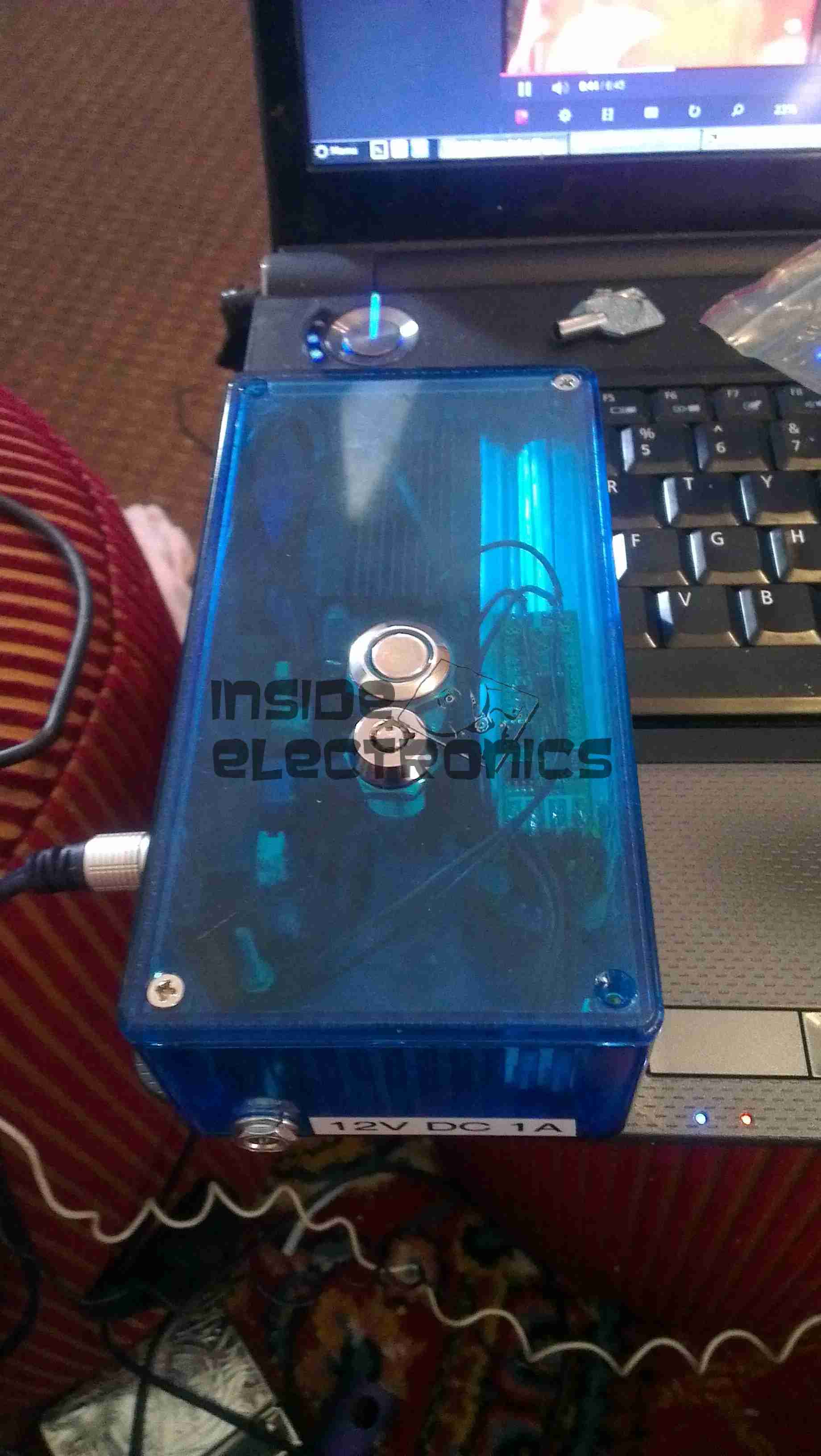
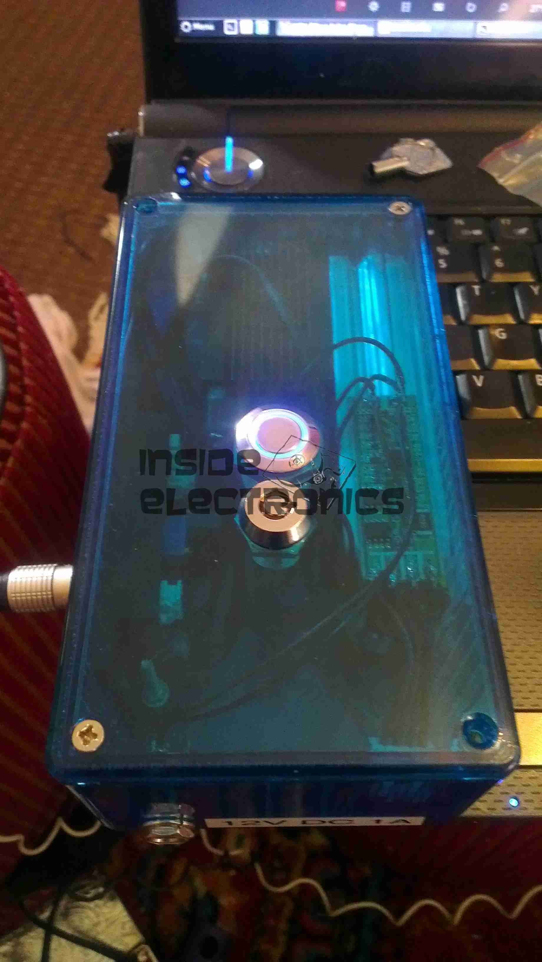
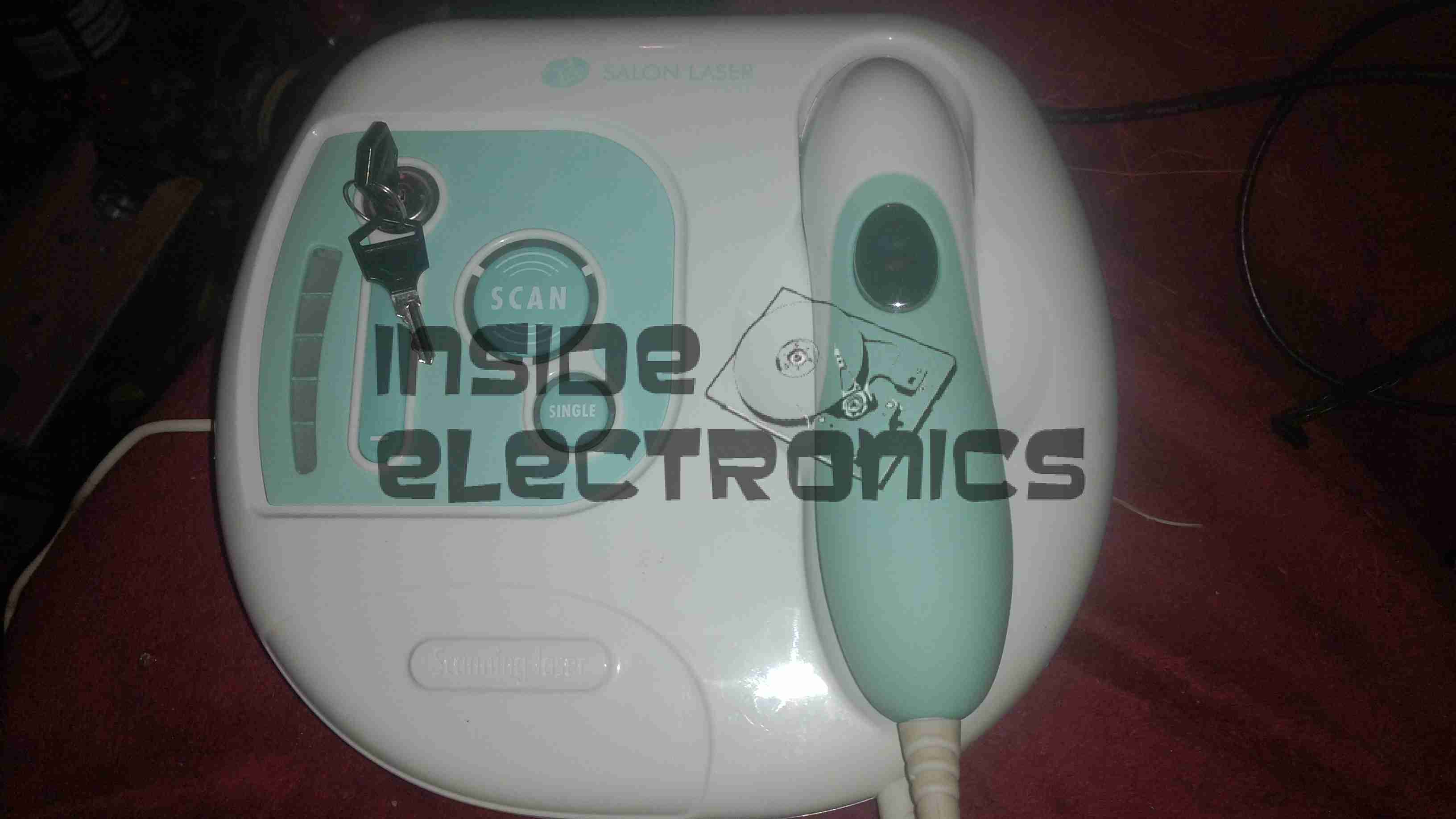
Here is a home laser hair removal unit, a Rio LAHS4. Shown above is the system overview, with the laser wand & the user controls.

Main PCB Top
Main PCB Top

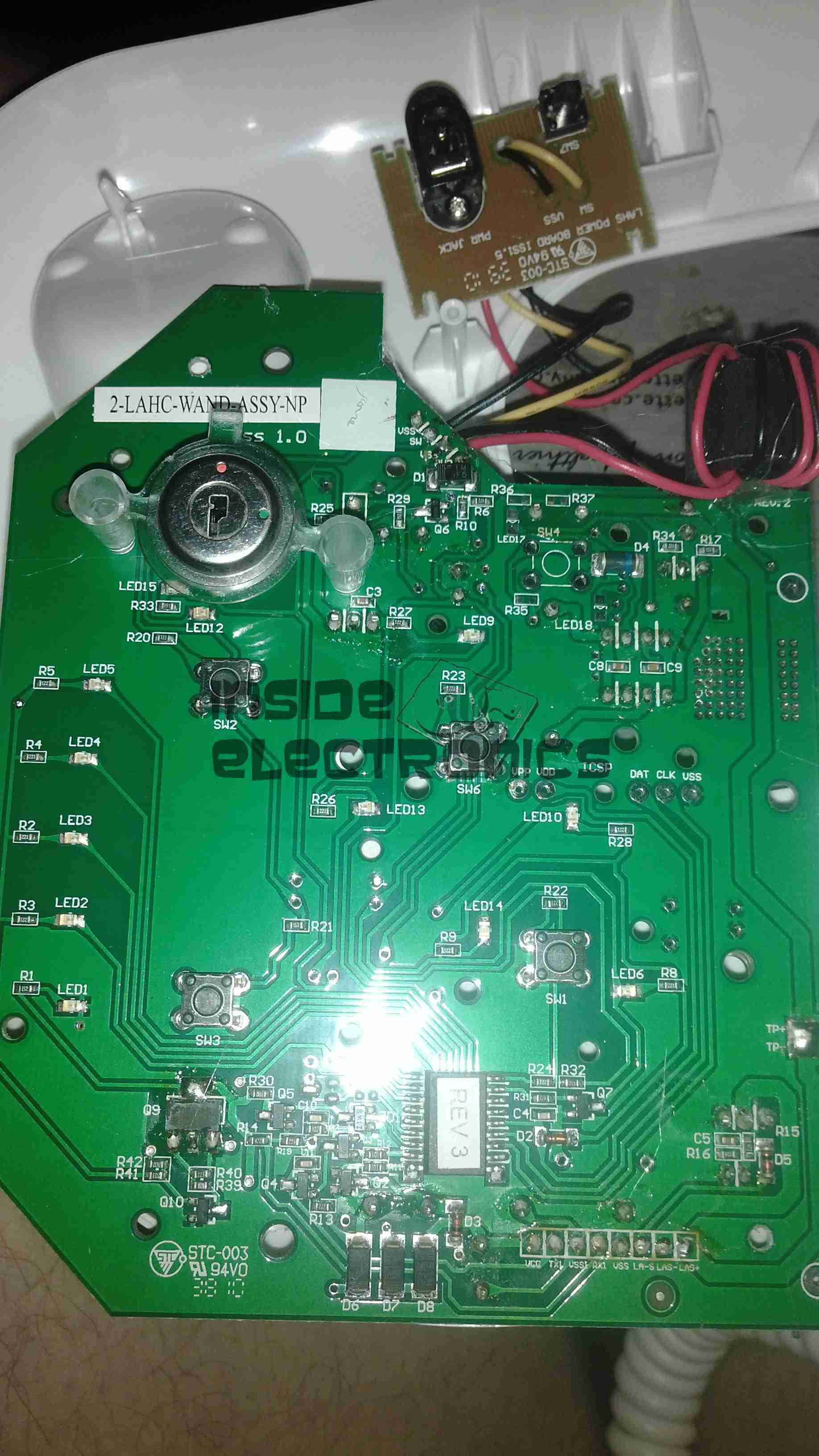
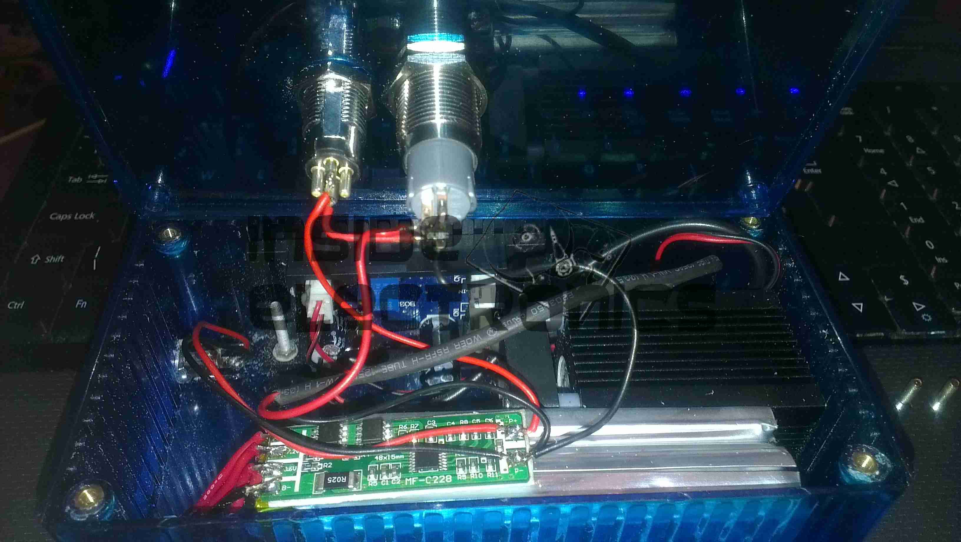
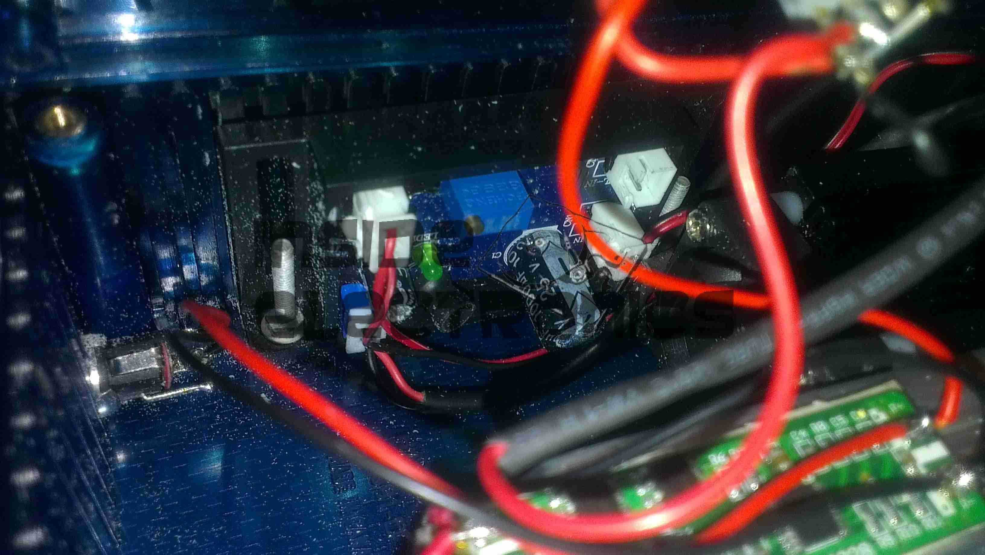
Main base unit popped open reveals the main PCB, with the central processor, a PIC16F628A.

Main PCB Bottom
Main PCB Bottom

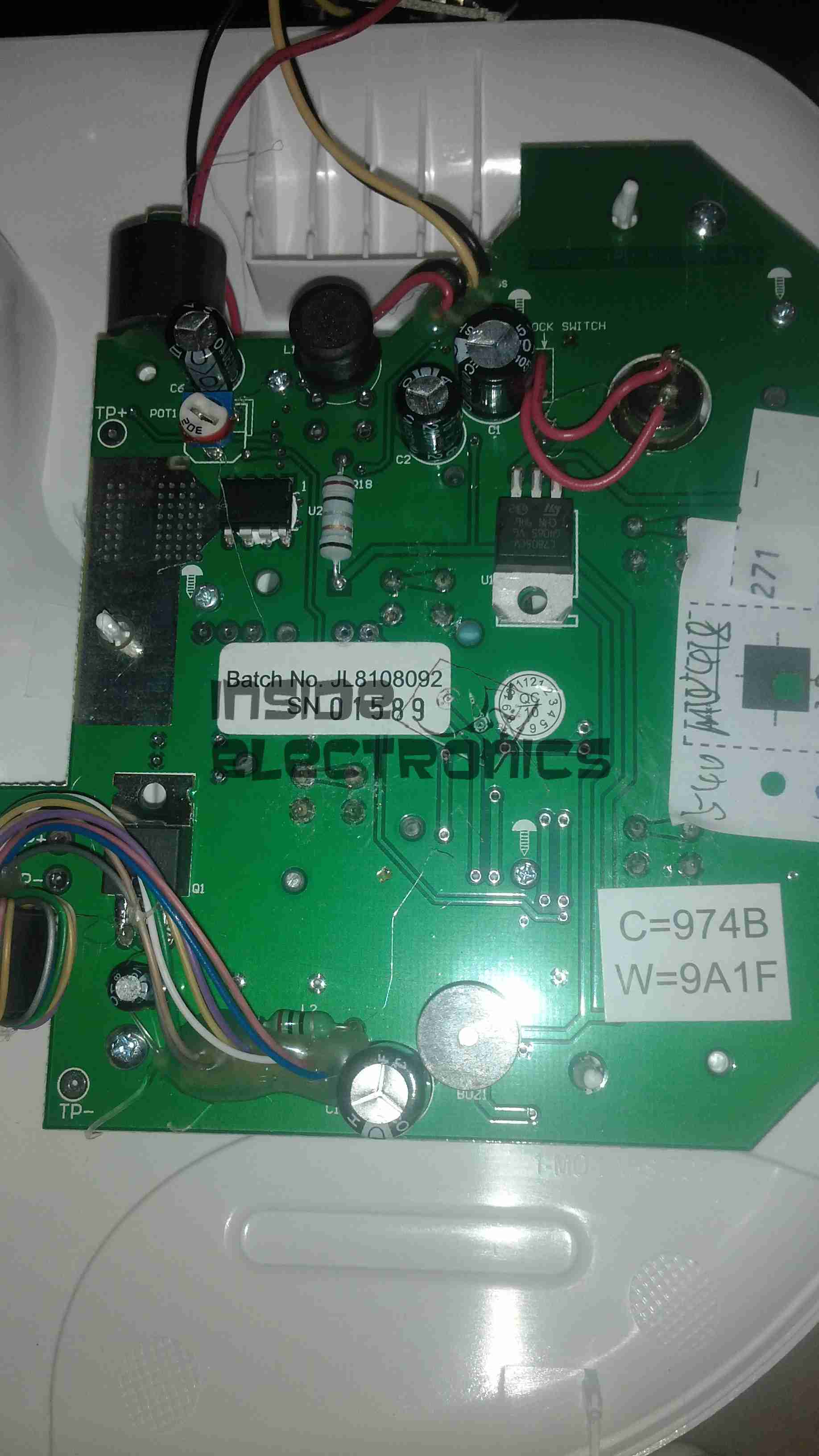
Other side of the PCB is mainly populated with power supply & filtering for the logic sections.

Wand PCB
Wand PCB

Cracking open the laser wand reveals a stacked pair of PCBs, a main laser controller & the capacitive sensor PCB. This capacitive sensor connects to a pair of pins on the laser head & prevents operation if the unit is not held firmly against the skin.

Diode Module
Diode Module

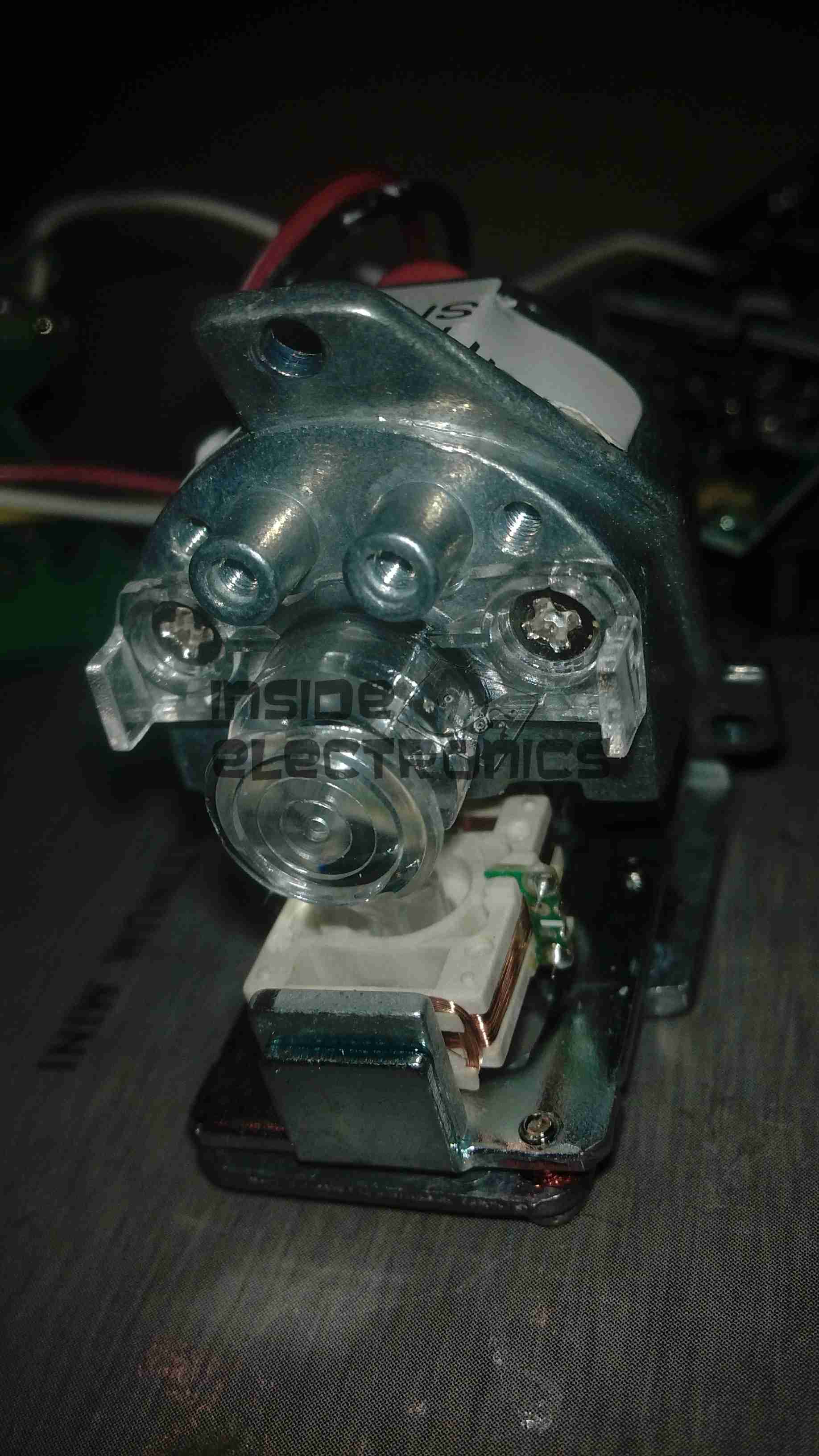
Front of the laser diode module with the movable lens, on a pair of voice coil actuators. Very similar to the lens positioner used in any CD/DVD player pickup assembly.
The diode in this unit is an 808nm chip, with power in the 300-600mW range most likely.

Diode Module Rear
Diode Module Rear

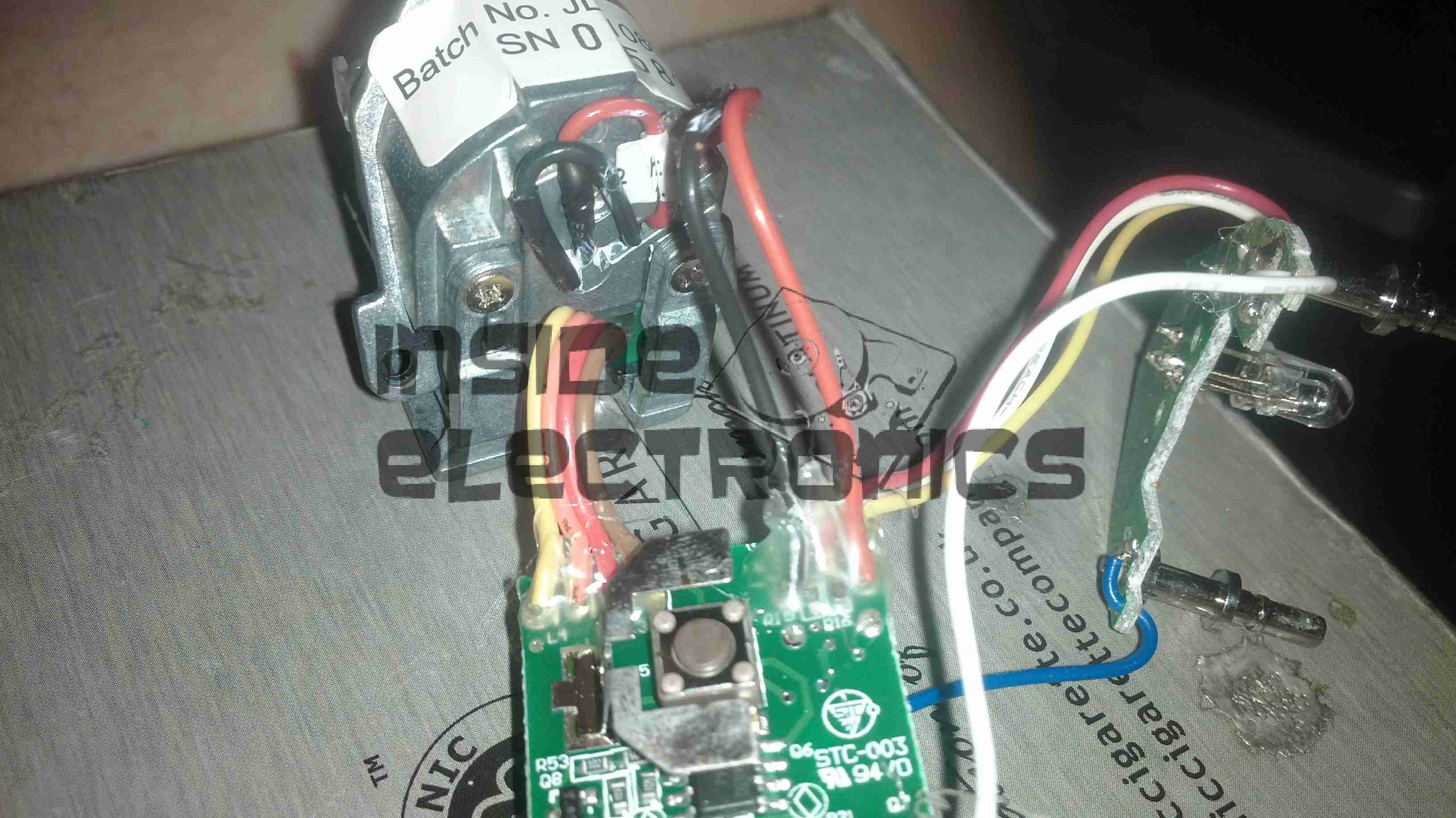
Rear of the diode module, with the connections to the diode itself & the voice coil positioner for the lens.

Wand PCB Top
Wand PCB Top

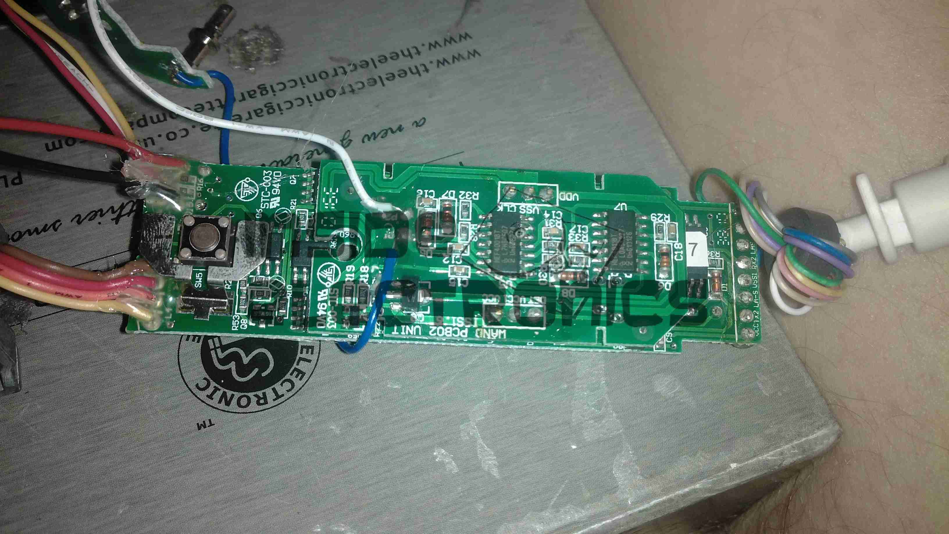
Other side of the wand PCB, showing the capacitive sensor board on top of the main controller board. There is another CPU on the board here, which most likely communicates with the main processor in the base through a serial connection.


Posted on Leave a comment

1.5W 445nm Lab Laser

Assembled
Assembled

Here is a followup from the 1.5W laser module post.

The module has been fitted into a housing, with a 2.2Ah Li-Poly battery pack. Charging is accomplished with an external 12.6v DC power supply.

Above can be seen the pair of switches on the top, the keyswitch must be enabled for the laser to fire.

Armed
Armed

When armed, the ring around the push button illuminates blue, as a warning that the unit is armed.

Switch Wiring
Switch Wiring

Inside the unit. The Li-Poly battery pack is at the bottom, with it’s protection & charging circuitry on the top. The switches are wired in series, with the LED connected to illuminate when the keyswitch is turned to the ON position.

Laser Driver
Laser Driver

The push button applies power to the laser driver module, which regulates the input power to safely drive the semiconductor laser in the aluminium heatsink housing.


Posted on Leave a comment

Vintage Optical Block

Top
Top

I thought this would be of interest, as it’s from a drive circa 2001, (DVD-CD-RW).

It’s the biggest & most complex optical block I’ve ever seen, with totally separate beam paths for the IR CD beam & the visible DVD beam. It also combines the use of bare laser diodes & combined diode/photodiode array modules for the pickup.


Cover Removed
Cover Removed

Here’s a look at the optics inside the sled, on the left is a bare laser diode & photodiode array, for the CD reading, and the bottom right has the DVD combined LD/PD array module. The beam from the CD diode has to pass though some very complex beam forming optics & a prism to fold it round to the final turning mirror to the objective lens at top center.
There are also two separate photodiodes which are picking up the waste beam from the prisms, most likely for power control.