Posted on Leave a comment

Quantum LTO2 CL1001 Tape Drive Teardown

Drive Top
Drive Top

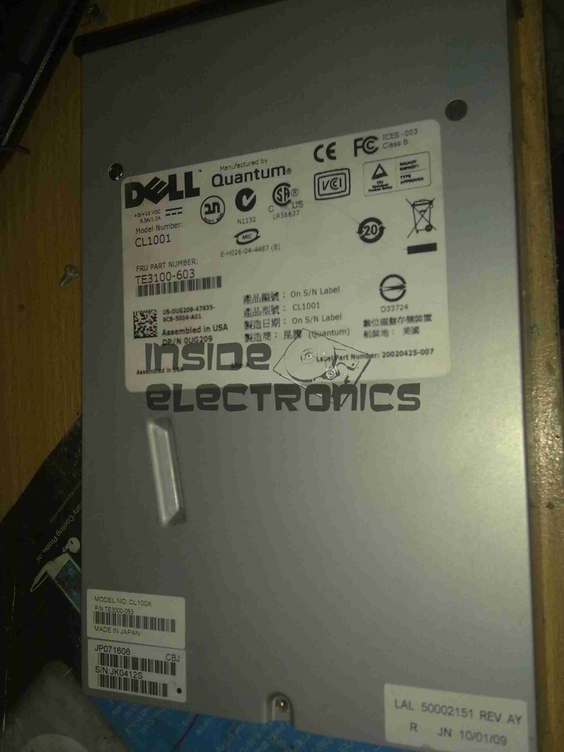
I have recently begun to create an archive of all my personal data, and since LTO2 tape drives offer significant capacity (200GB/400GB) per tape, longevity is very high (up to 30 years in archive), & relatively low cost, this is the technology I’ve chosen to use for my long term archiving needs.

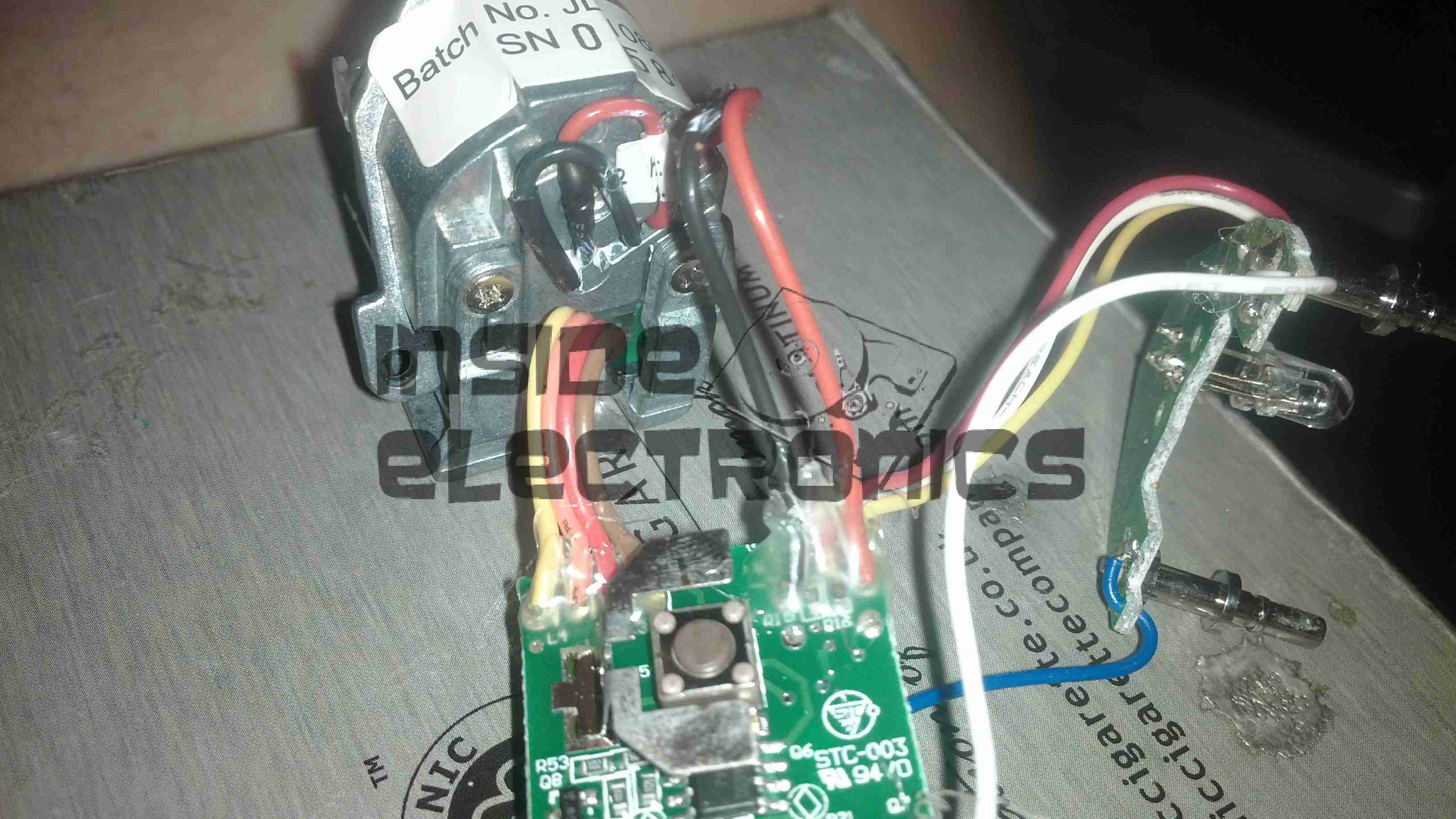
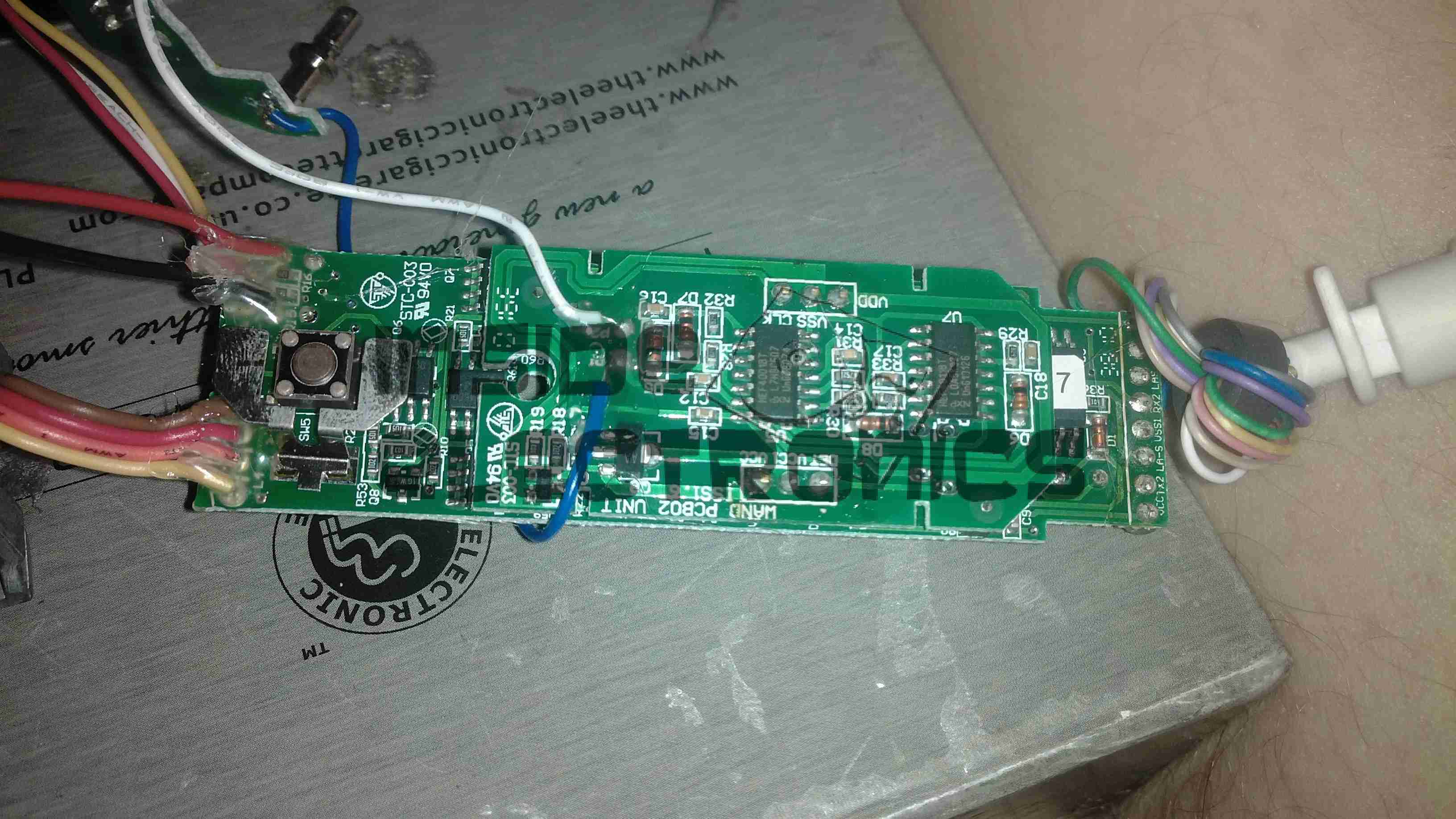
Unfortunately, this drive was DOA, due to being dropped in shipping. This drop broke the SCSI LVD connector on the back of the unit, & bent the frame, as can be seen below.

Broken SCSI
Broken SCSI

As this drive is unusable, it made for a good teardown candidate.

Cover Removed
Cover Removed

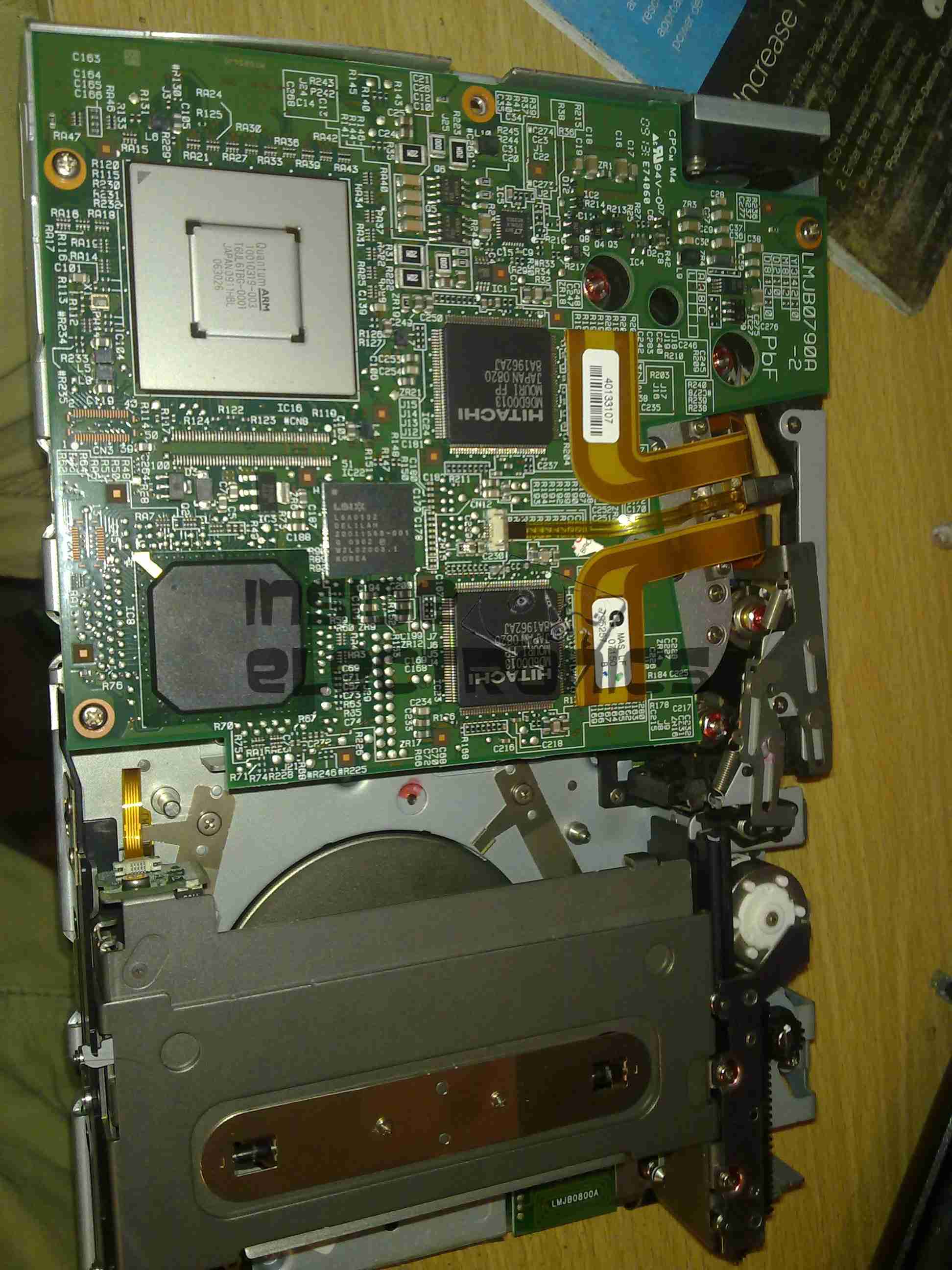
Here the top cover of the drive has been removed, showing the top of the main logic PCB. The large silver IC in the top corner is the main CPU for the drive. It’s a custom part, but it does have an ARM core.

The two Hitachi ICs are the R/W head interface chipset, while the smaller LSI IC is the SCSI controller.
The tape transport & loading mech can be seen in the lower half of the picture.

Main Logic
Main Logic

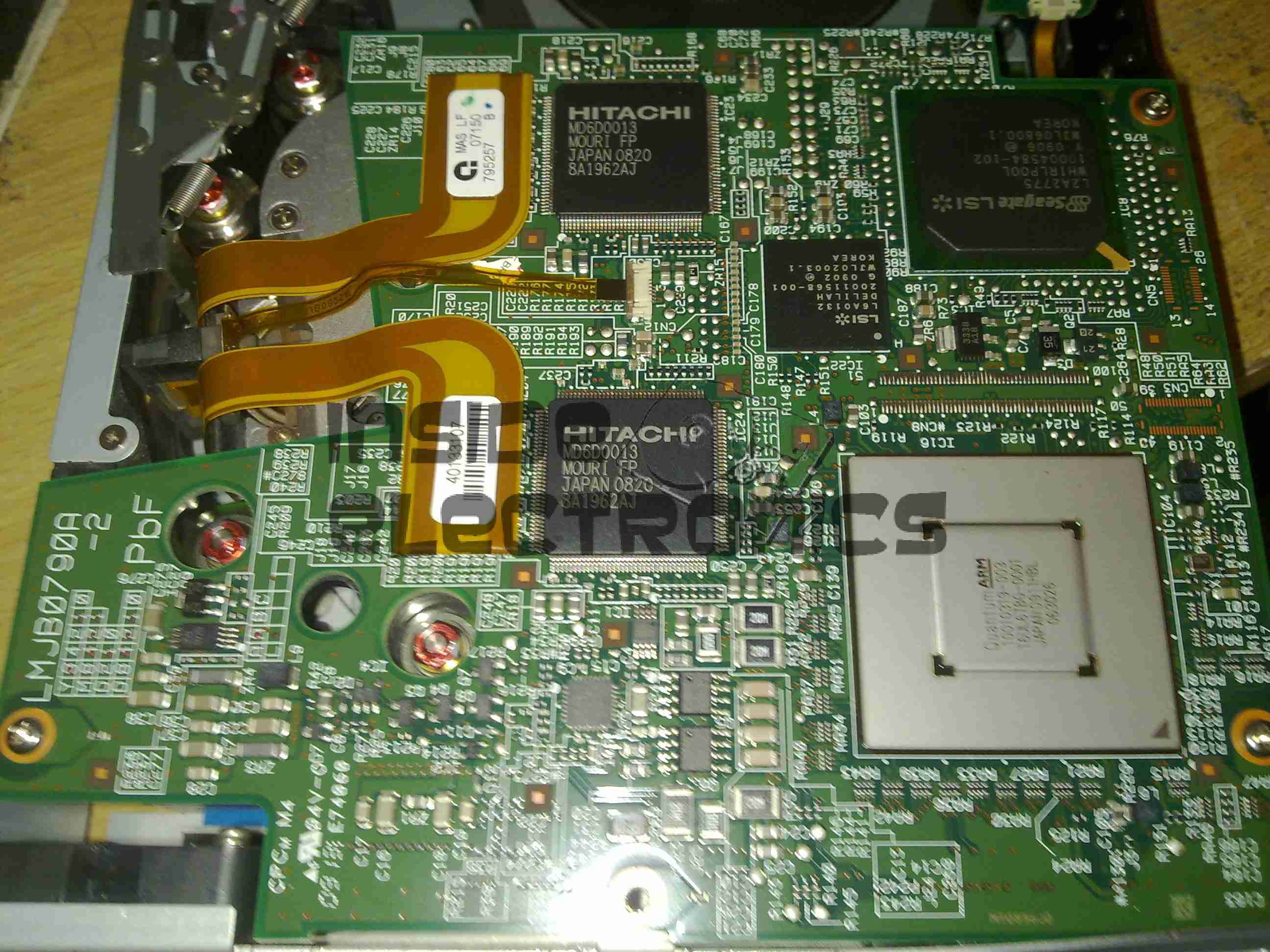
Close up of the main logic.

Tape Spool
Tape Spool

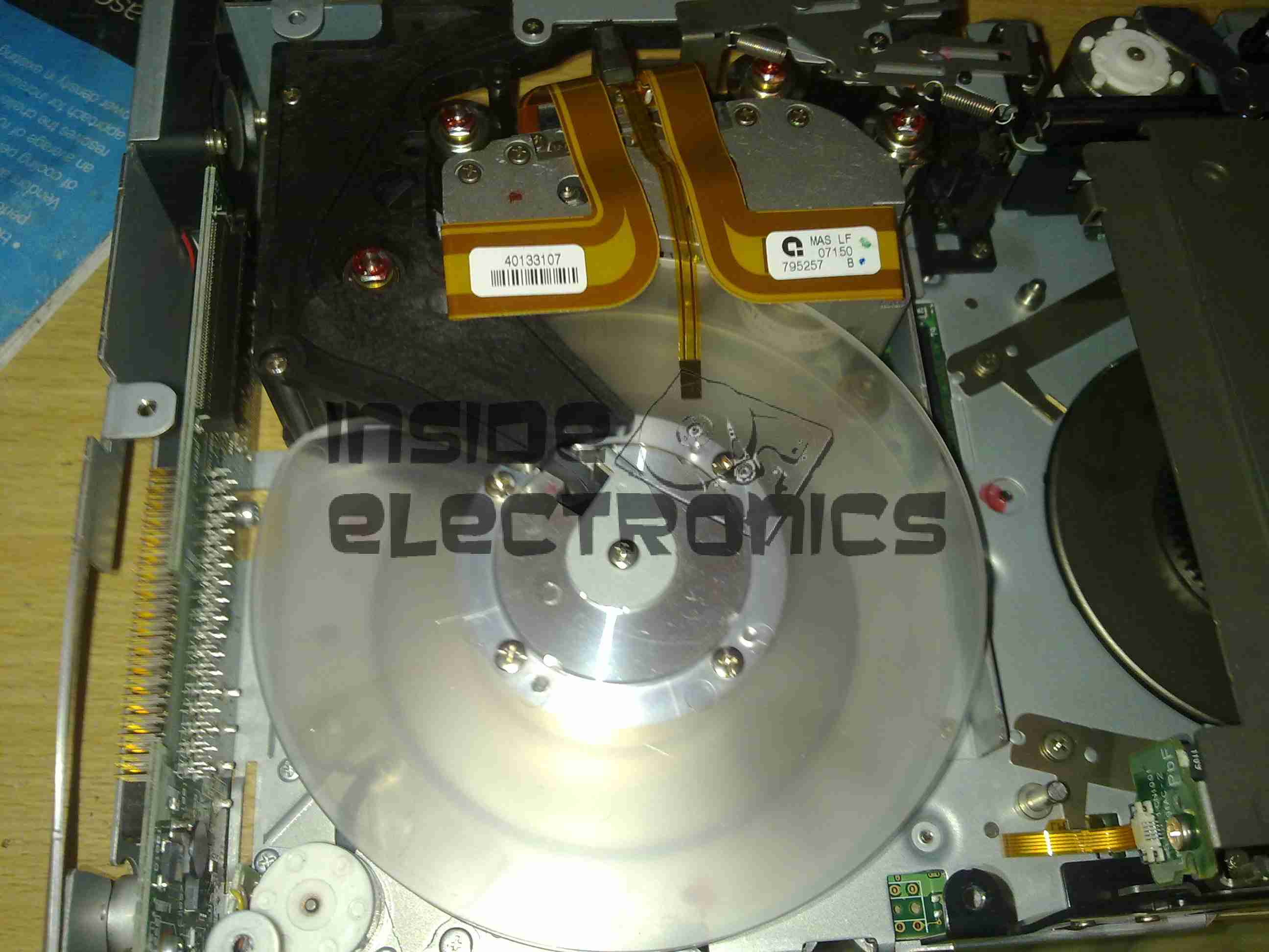
Here the main logic PCB has been removed, showing the tape take up spool. The data cartridges have only one spool to make the size smaller. When the tape is loaded, the drive grabs onto the leader pin at the end of the tape & feeds it onto this spool.
The head assembly is just above the spool.

Bottom Plate Removed

Bottom of the drive with the cover plate removed. Here the spindle drive motors are visible, both brushless 3-Phase units. Both of these motors are driven by a single controller IC on the other side of the lower logic PCB.

Head Drive Motor
Head Drive Motor

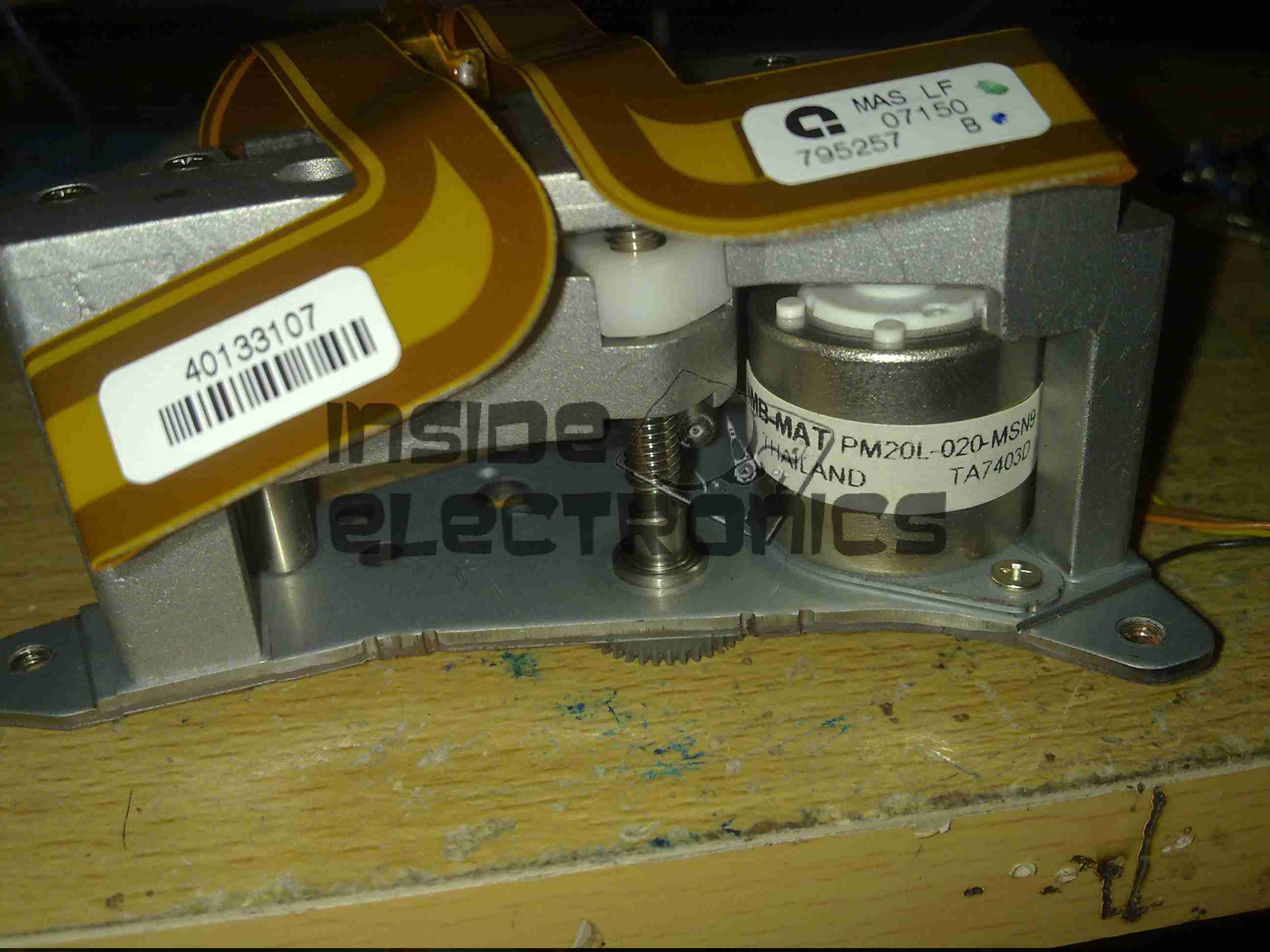
The head is moved up & down the face of the tape by this stepper motor for coarse control, while fine control is provided by a voice coil assembly buried inside the head mount.

Tape Head Assembly
Tape Head Assembly

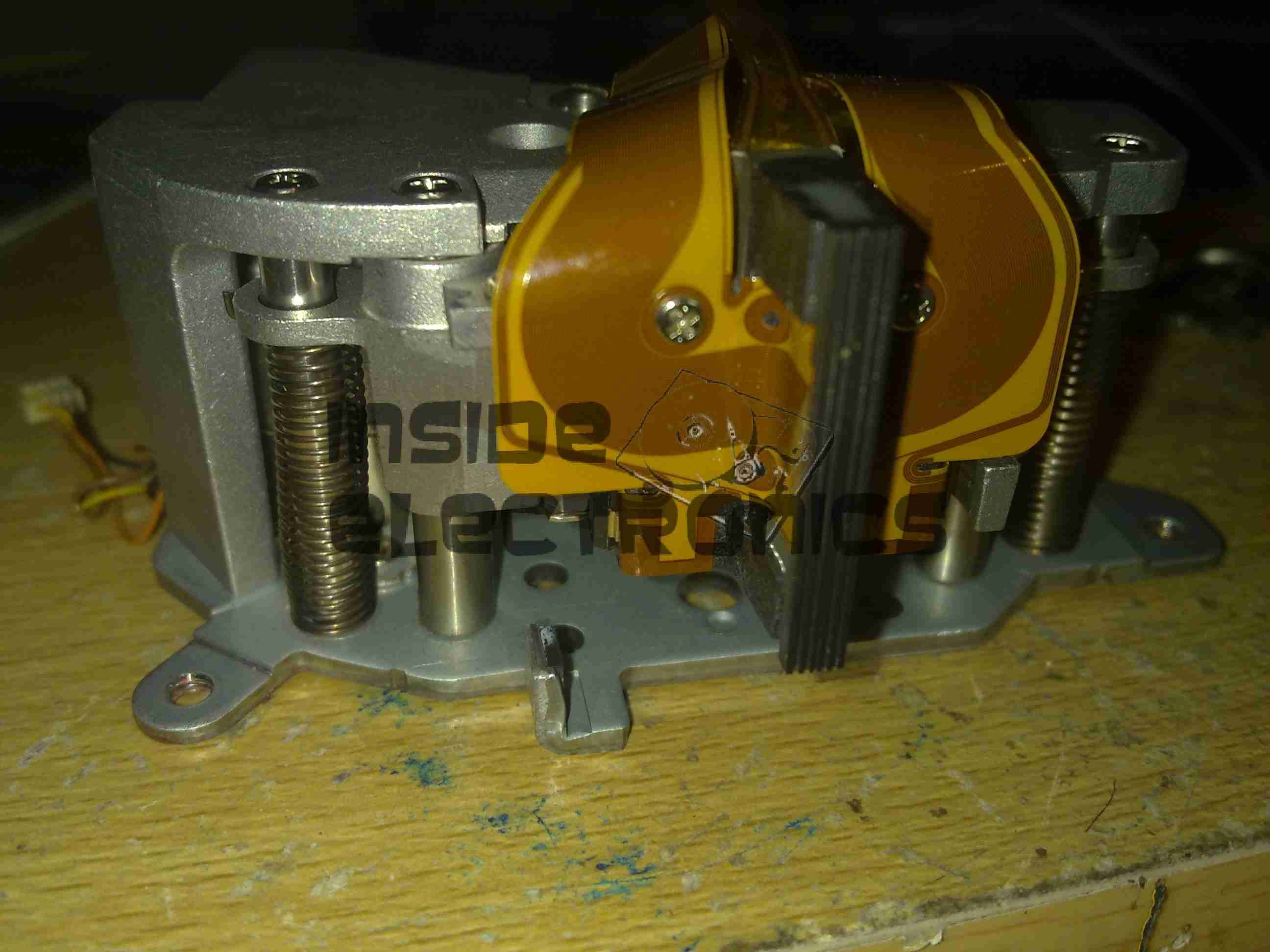
The face of the tape R/W head. This unit contains 2 sets of 8 heads, one of which writes to the tape, the other then reads the written data back right after to verify integrity.

Cartridge Load Motor

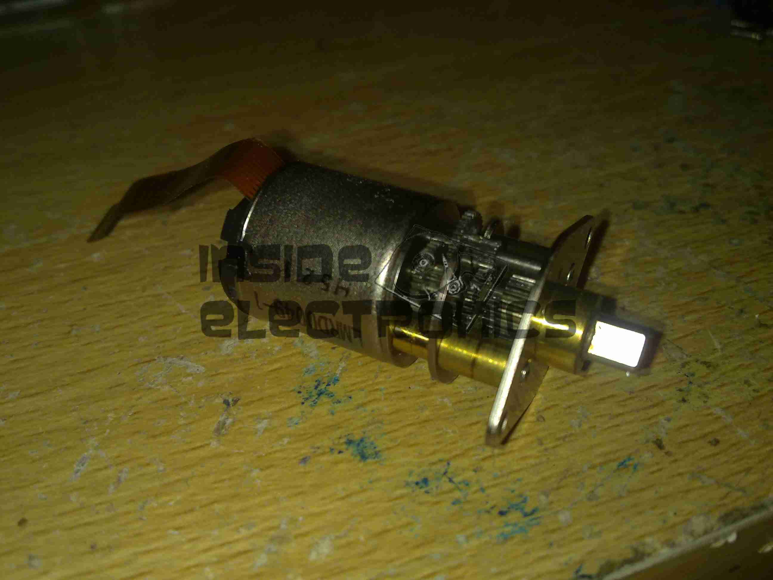
The tape cartridge loading motor. I originally thought that this was a standard brushed motor, but it has a ribbon cable emerging, this must be some sort of brushless arrangement.

A replacement drive is on the way, I shall be documenting some more of my archiving efforts & system setup once that unit arrives.

Posted on Leave a comment

Rio LAHS4 Salon Laser Hair Remover

Unit Overview
Unit Overview

Here is a home laser hair removal unit, a Rio LAHS4. Shown above is the system overview, with the laser wand & the user controls.

Main PCB Top
Main PCB Top

Main base unit popped open reveals the main PCB, with the central processor, a PIC16F628A.

Main PCB Bottom
Main PCB Bottom

Other side of the PCB is mainly populated with power supply & filtering for the logic sections.

Wand PCB
Wand PCB

Cracking open the laser wand reveals a stacked pair of PCBs, a main laser controller & the capacitive sensor PCB. This capacitive sensor connects to a pair of pins on the laser head & prevents operation if the unit is not held firmly against the skin.

Diode Module
Diode Module

Front of the laser diode module with the movable lens, on a pair of voice coil actuators. Very similar to the lens positioner used in any CD/DVD player pickup assembly.
The diode in this unit is an 808nm chip, with power in the 300-600mW range most likely.

Diode Module Rear
Diode Module Rear

Rear of the diode module, with the connections to the diode itself & the voice coil positioner for the lens.

Wand PCB Top
Wand PCB Top

Other side of the wand PCB, showing the capacitive sensor board on top of the main controller board. There is another CPU on the board here, which most likely communicates with the main processor in the base through a serial connection.


Posted on Leave a comment

IDE Zip Drive

Top
Top

An old IDE interface Zip drive. This fits in a standard 3.5″ bay.

Cover Removed
Cover Removed

Top cover removed from the drive, IDE & power interfaces at the top, in centre is the eject solenoid assembly & the head assembly. Bottom is the spindle drive motor.

Head Assembly
Head Assembly

Head assembly with the top magnet removed. Voice coil is on the left, with the head preamp IC next to it. Head chips are on the end of the arm inside the parking sleeve on the right. Blue lever is the head lock.

Controller
Controller

Controller PCB removed from the casing.

Spindle Motor
Spindle Motor

Spindle motor. This is a 3-phase DC brushless type motor. Magnetic ring on the top engages with the hub of the Zip disk when insterted into the drive.

Magnets
Magnets

Magnets that interact with the voice coil on the head assembly.

Head Armature
Head Armature

Head armature assembly removed from the drive. The arm is supported by a pair of linear bearings & a stainless steel rod.

Posted on Leave a comment

Western Digital 160GB 2.5″ HDD

Top Of Drive With Label
Top

This is a Western Digital drive recently removed from my laptop when it died of a severe head crash.
Top of drive can be seen here.

Top Removed From Drive
Top Removed

Here the cover has been removed from the drive, showing the platter, head arm & magnet. Yellow piece top left is head parking ramp.

Head Arm of Drive
Head Arm

The head assembly of the drive is shown here. The head itself is on the left hand end of the arm in the plastic parking ramp. The other end of the arm holds the voice coil part of the head motor, surrounded by the magnet.

Bottom Of Drive with PCB

Bottom of drive, with controller PCB. SATA interface socket at bottom.

PCB removed from bottom of drive. Spindle motor connections & connections to the head unit can be seen on the bottom of the drive unit.

Controller PCB. Supports the cache, interface & motor controller ICs.

Closeup of the motor driver IC, this controls the speed of the spindle motor precisely to 5,400RPM. Also controls the voice coil motor controlling the position of the head arm on the platters.

Interface IC closeup. This IC receives signals from the head assembly & processes them for transmission to the SATA bus. Also holds drive firmware, controls the Motor driver IC & all other functions of the drive.

Cache Memory IC.