I posted a couple of weeks back that I was soon to be the recipient of a new gigabit symmetric link to the intertubes – and there was a bit of a caveat of their use of CG-NAT due to the exhaustion of the IPv4 address space.
To compensate I’ve routed everything over a VPN link in prep for this new connection, which does work fantastically well.
After a chat with their support guys – and I did actually manage to speak to someone in their Networks team, not just a customer support droid(!), they will soon be introducing a service where I can add a public IPv4 to my account, so I’ll be able to run at full gigabit speeds without the 100Mbit restriction of this VPN connection!
I’m told that this will be within the next couple of months, which is around the same lead time as the connection itself, so hopefully this will be live just in time for my new fibre.
Everyone who reads this website will know about the cost of living crisis – this is a global problem brought about by the combination of the Covid-19 pandemic, and the unfortunate situation in Ukraine at the present time.
For us in the UK, the costs of energy have skyrocketed in recent months, with our government permitting the energy companies to charge us all an extra £600 per year in electricity alone. Given I run servers, this isn’t particularly good news.
The cost of running the network infrastructure behind this blog is not insignificant – just the server alone runs me around £30-£40 per month just in power, and add onto that the £45 in connectivity costs. I don’t meter the power taken by the router, switch etc, so the total cost will be marginally higher.
Given the increases that have hit, I expect to see a 3x increase in power costs to run this blog on the current hardware – an unsustainable jump.
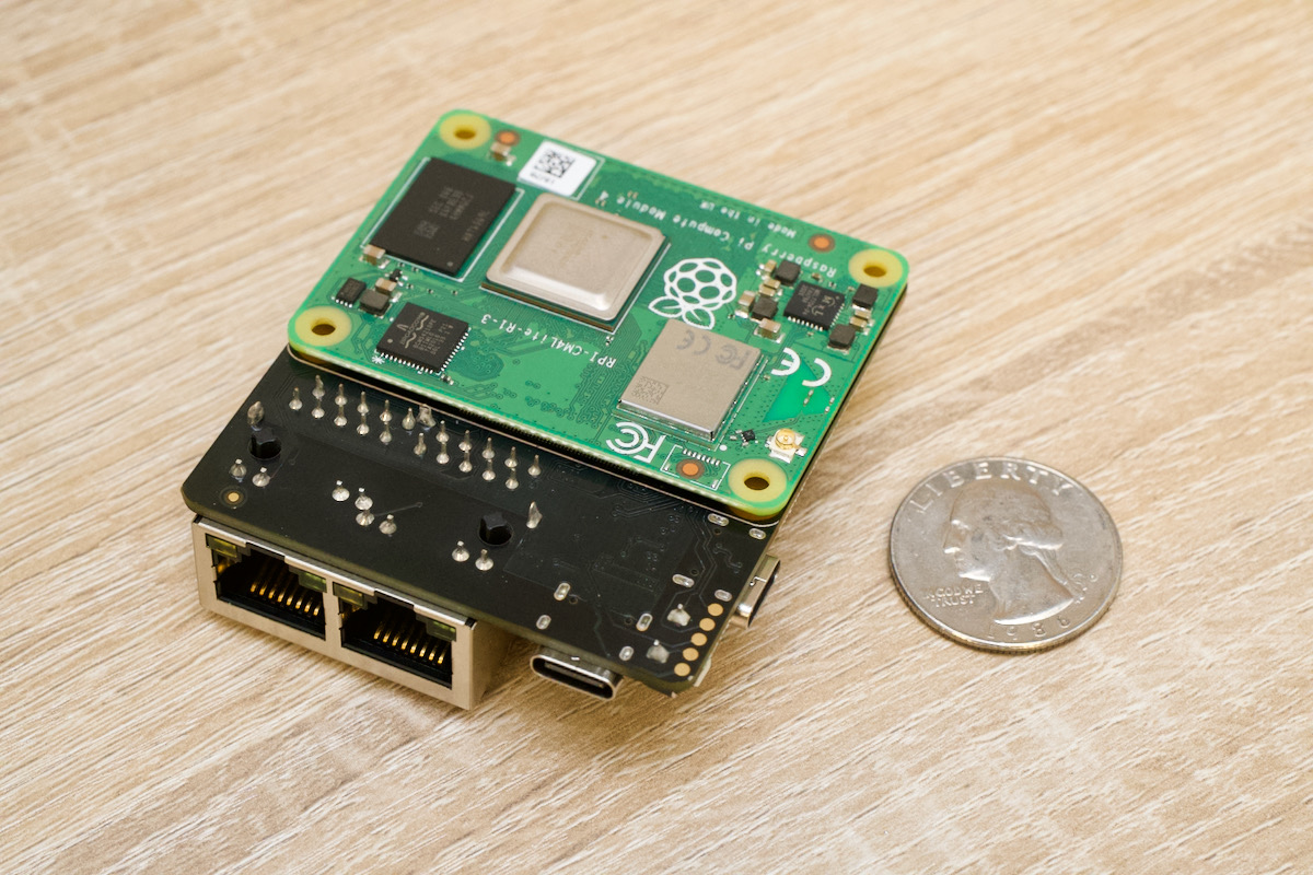
I’ve got a couple of Raspberry Pi’s floating around, at the moment uncommitted to any tasks, so I thought I’d use one of these. A Pi CM4 module in a support PCB with dual network links should so just fine. I ogirinally got this to build a Pi based router (what it was designed for) – nevermind!
I’m using the new 64-Bit version of Raspberry Pi OS, and a 128GB MicroSD card for storage, since this board doesn’t have an open PCIe lane for a NVMe drive.
A quick setup with Nginx, php-fpm & MariaDB & I’m in business! The site is now running on a Raspberry Pi! As a plus, everything does seem to be quicker than the old Apache setup too. I have for now dropped a few features of the site, just until I get a feel of how quick this new setup is going to be, but they should be back soon!
For 90% of the time I’ve run this website, it’s been run from a server in my house, over a domestic-grade ADSL connection. The problem has always been the very asymmetric download/upload bandwidth provided by domestic ISPs. Normally it’s about a 10:1 ratio these days (the current connection is 350MBit DL / 20MBit UL, which is even worse). Going back a few years, this wasn’t much of an issue – 99.9% of general ISP customers didn’t need a high upload rate, as they were only requesting web addresses, etc. Nowadays especially with the rise of online video services & social media, upload rates are more important than ever, since a good proportion of the population is uploading their own content daily.
Despite these changes in how the networks are utilised by the end users, the upload rates haven’t really improved much, which I’ve always found baffling.
Considering the bandwidth limitations imposed by such a connection on upload rates, the site’s done pretty well over the years, even though it can be a touch slow at times. I’ve been looking at changing this situation for a long time, watching to see if any of the direct fibre ISPs in the UK were going to get around to serving my area, such as Gigafibre, CityFibre or HyperOptic, but they unfortunately haven’t yet appeared anywhere near my locale.
Cue the entry of a new ISP: Brsk. These guys are building an entirely new fibre network, and just so happen to be doing the network build in my direct area at the moment. For only £5 more a month than I’m paying for the service I have now, I can now obtain full gigabit symmetric connectivity!
There’s one small caveat to the service, which wouldn’t bother the average member of the public, is a serious block to how I use my internet connectivity – they don’t hand out globally addressable IPv4 addresses. This is ostensibly due to the global IPv4 address shortage. Instead, they use CGNAT to address their endpoints, which renders me unable to route anything out to the global internet from my connection. Luckily there are ways around this issue.
I do have access to some public IPv4 addresses that are currently unallocated, in another networking installation, which also runs a VPN into my home network. So it’s just a matter of hooking up my primary server to that VPN, and routing one of the spare IPv4s over the private link from the router at the other site. This will limit thing somewhat, as the other site link is a 100MBit symmetric leased-line, however that’s still an 80MBit improvement in upload rate overall.
This latter solution of routing a public IP over VPN to a private endpoint is something I’ve already done in preparation – and it works great. The firewall on the site router provides extra protection for the server, and even with the VPN overhead it’s just as quick as it was before.
Since they’re still building out the network, I’ve only been able to place a preorder, and the connection will be installed (allegedly) sometime in July. Once the new link is in, I can get rid of my existing provider.
Once the link’s installed I’ll provide some updates!
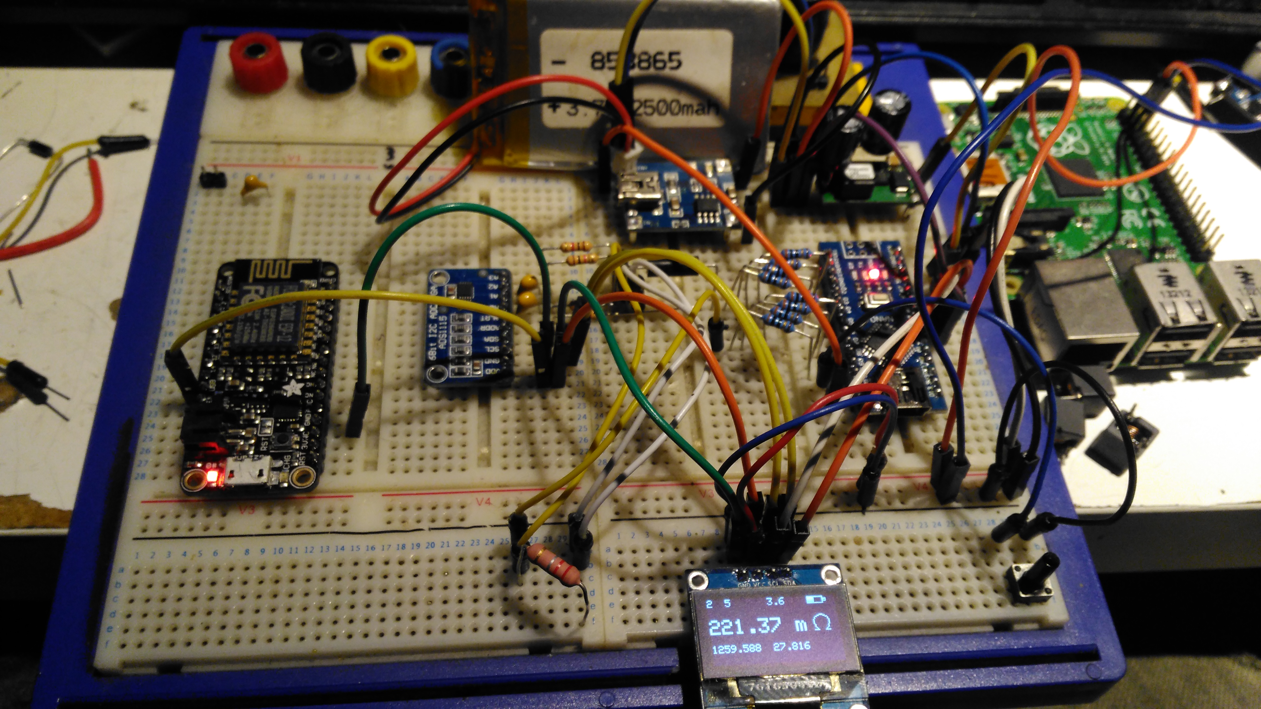
I’ve been looking for ways to build a DIY Laser Power meter for some time now, but I had no way to calibrate anything. I have been aware of DIY thermopile sensors with TECs – but no way to verify any results until now. Since I have my Gentec meter to calibrate against, I can finally get on with the project.
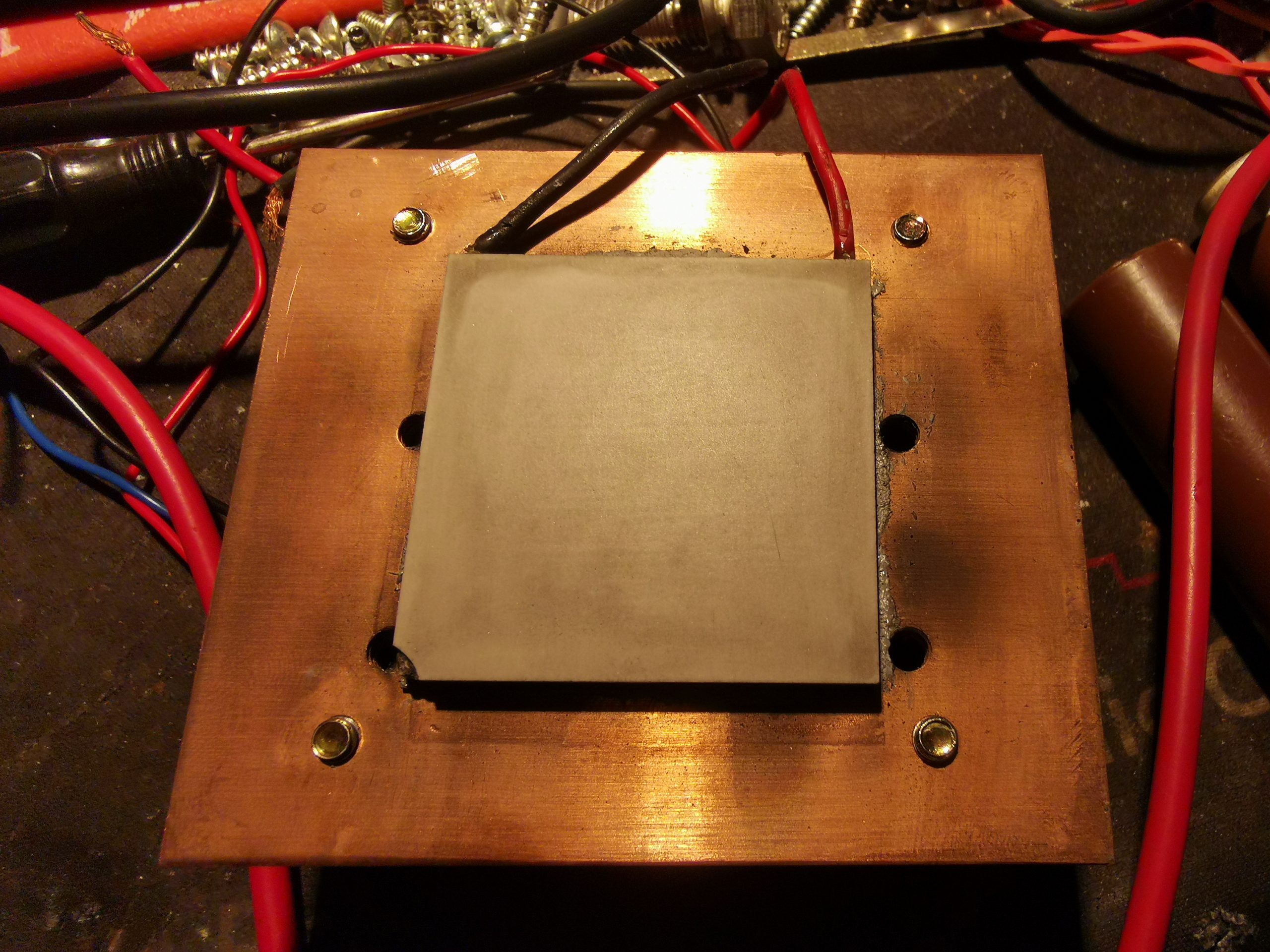
In the photo above, is the Peltier/TEC module mounted to the heatsink with thermal compound. In this case it’s a TEC1-12706, pulled from a cheapo dehumidifier. The cold face (with the part number printing) is against the heatsink, and the hot face will serve as the beam target. This was cleaned with solvent, and roughed up a bit with silicon carbide abrasive paper – the abrasive needs to be harder than the Alumina ceramic the module is constructed from.
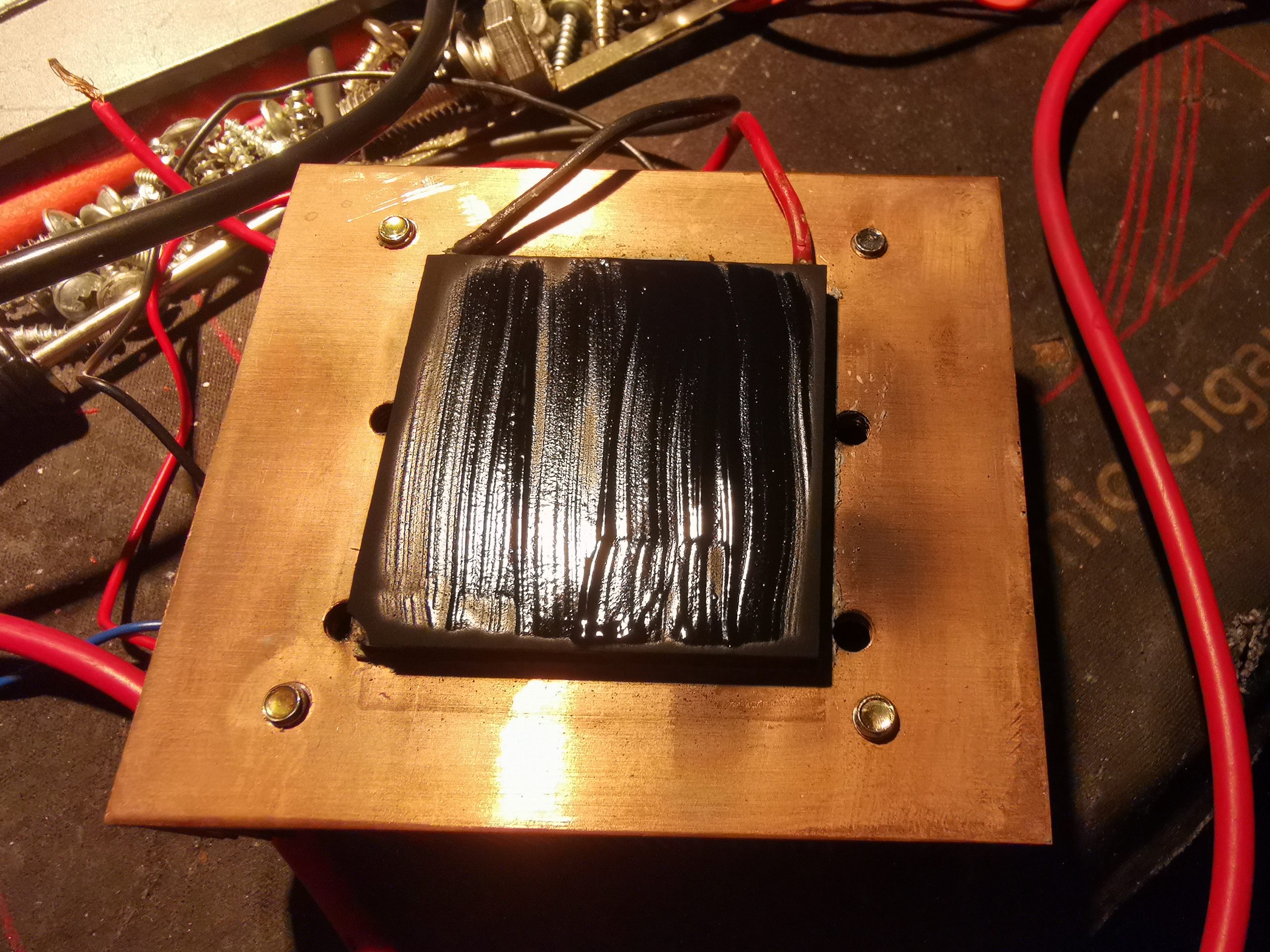
Optical Coating
To be any good as an optical power sensor, the front face of the module needs to be coated with something to absorb as much energy from the laser beam as possible. In this case, black paint was used, as it’s completely matte when dried. Lampblack also works, and this can be coated onto a sensor face with just a wax candle, but this is far too fragile to be any practical use (being just carbon, it’s much more resistant to thermal damage from the laser beams though!).
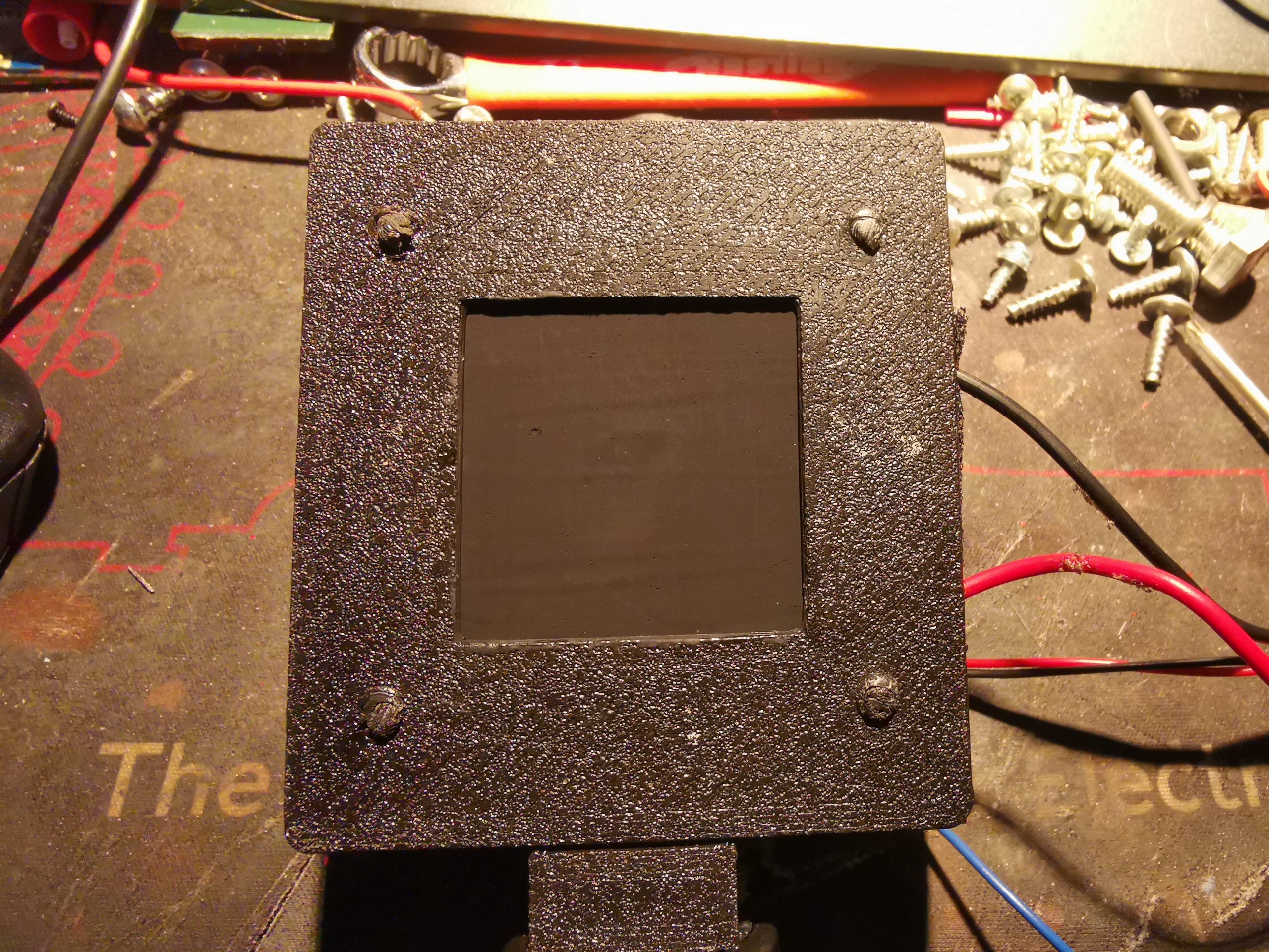
Coated Sensor
After two coats of the paint are applied to the front face of the module, the sensor head is complete. Try to get this as smooth as possible for best results. I designed & 3D printed a retention bracket for the module, and matches up with the screws that hold the fan on the finned side. This also has a block on the bottom which I threaded 1/4-20 to fit a standard tripod thread.
Like all commercial laser power sensors, the beam should be expanded as much as possible to fill the full face of the sensor. A focused high-power beam will quickly destroy the coating!
After completion, the sensor needs to be characterised. For this I set a diode module to be as close to 1W as possible, according to my calibrated meter, and applied the beam to the constructed sensor. A load impedance of 68Ω was placed across the output leads as a load. For this unit, I obtained a reading of 83.5mV/W of applied power. Even for low power levels, the fan does need to be running on the back of the heatsink, as the cold side of the sensor heating up will skew the reading.
After calibration at 1W optical power, I then ran some more tests at higher powers – 2W gave exactly double the output voltage, and throughout the power range I am able to test, the sensor seems to be entirely linear in operation.
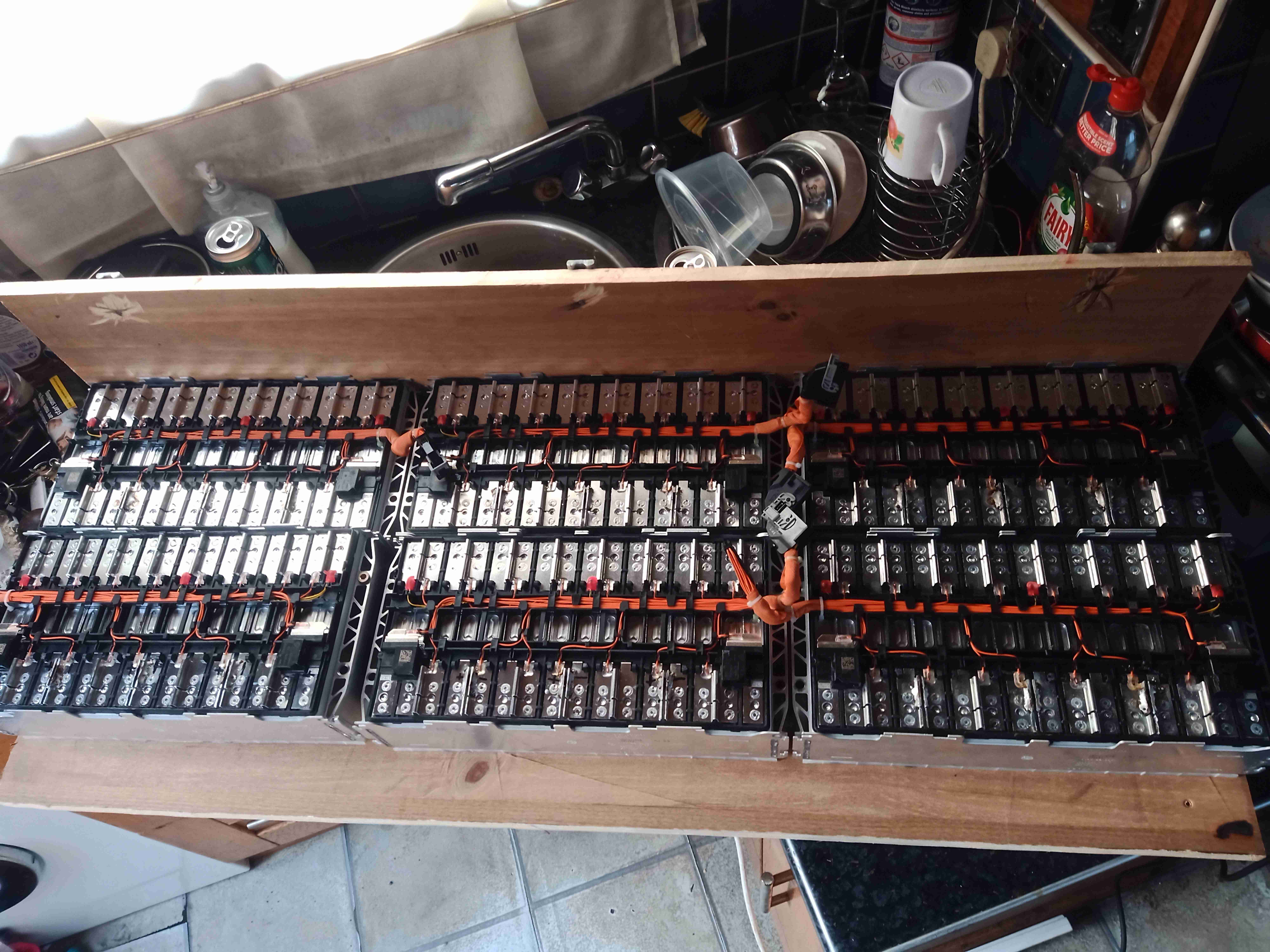
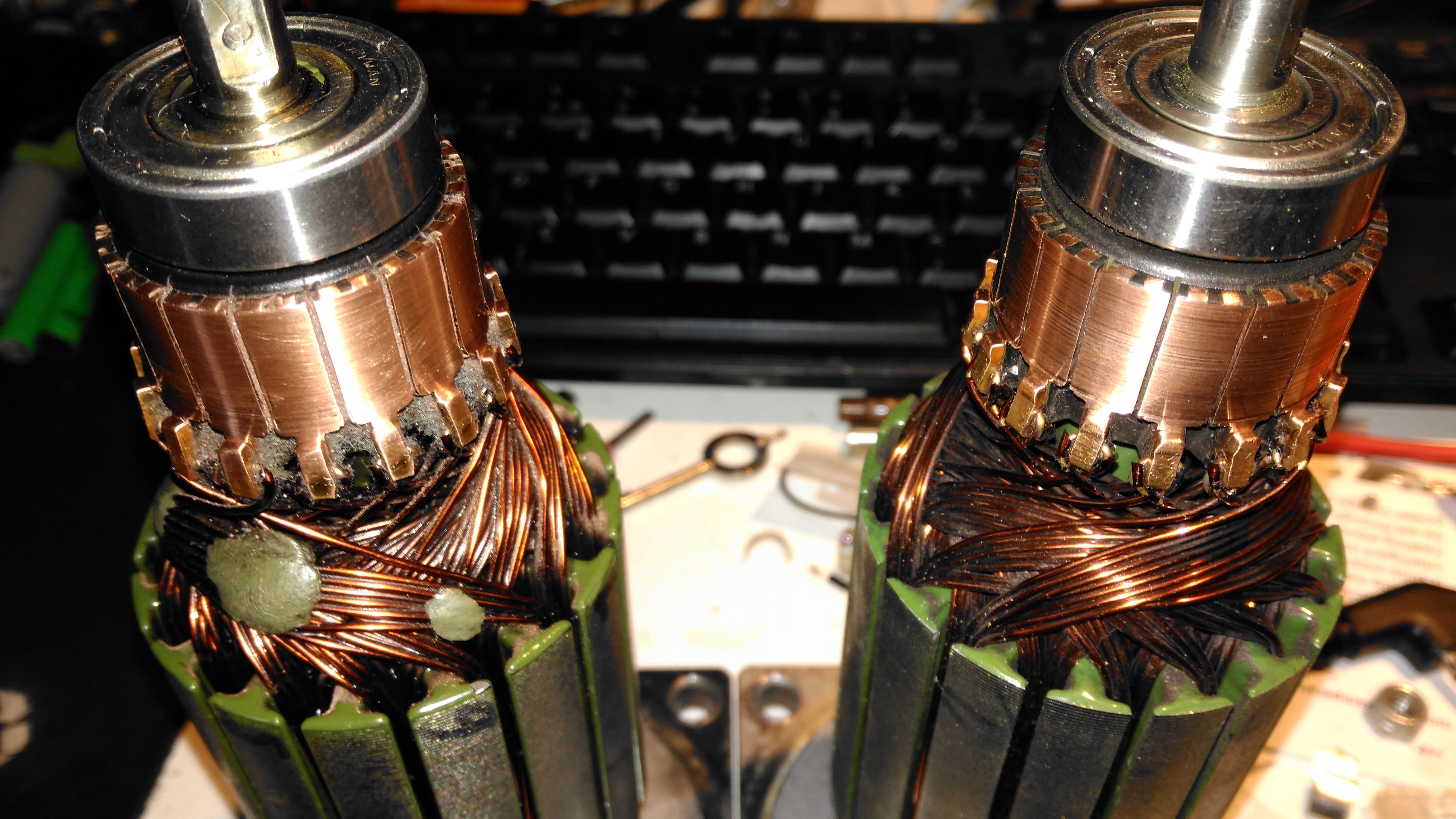
Now the cell modules have been removed from their original home, it’s time to get them repurposed! A custom mounting board has been constructed from timber, and the modules mounted on them. To say this assembly is heavy would be an understatement – it’s barely a two-man lift!
As assembled in the car, the pack as 96S1P, with every cell in series. As we need a low voltage bus, the modules have been reconfigured for 4S4P, in total this makes 4S24P with all 6 modules bussed together. As the cell interconnects are laser welded, some ingenuity was required here.
It turned out the best method (and the safest, to avoid any swarf shorting out cells!), was to use a grinder to cut off the top of the loop on the aluminium interconnects, separating them.
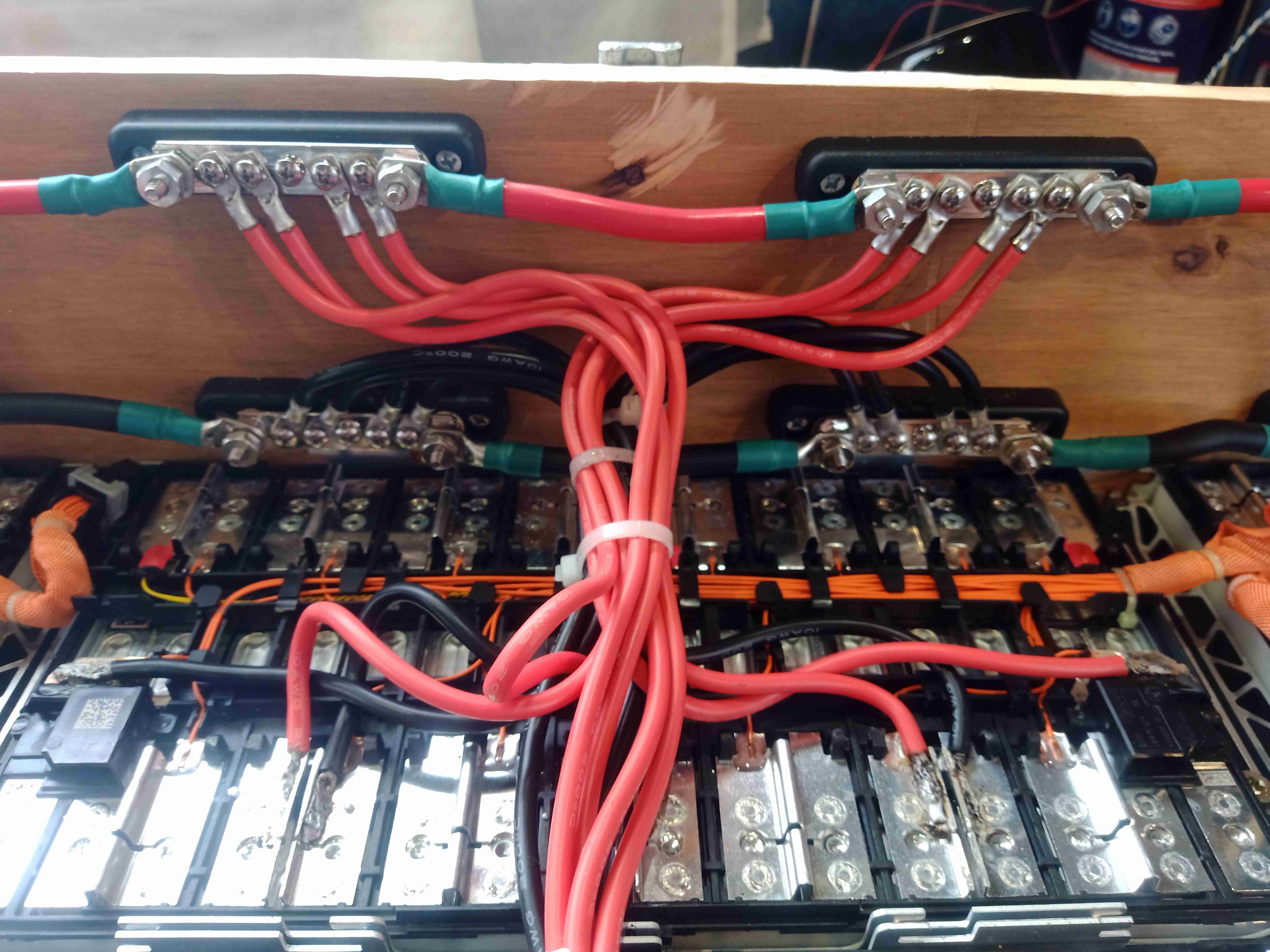
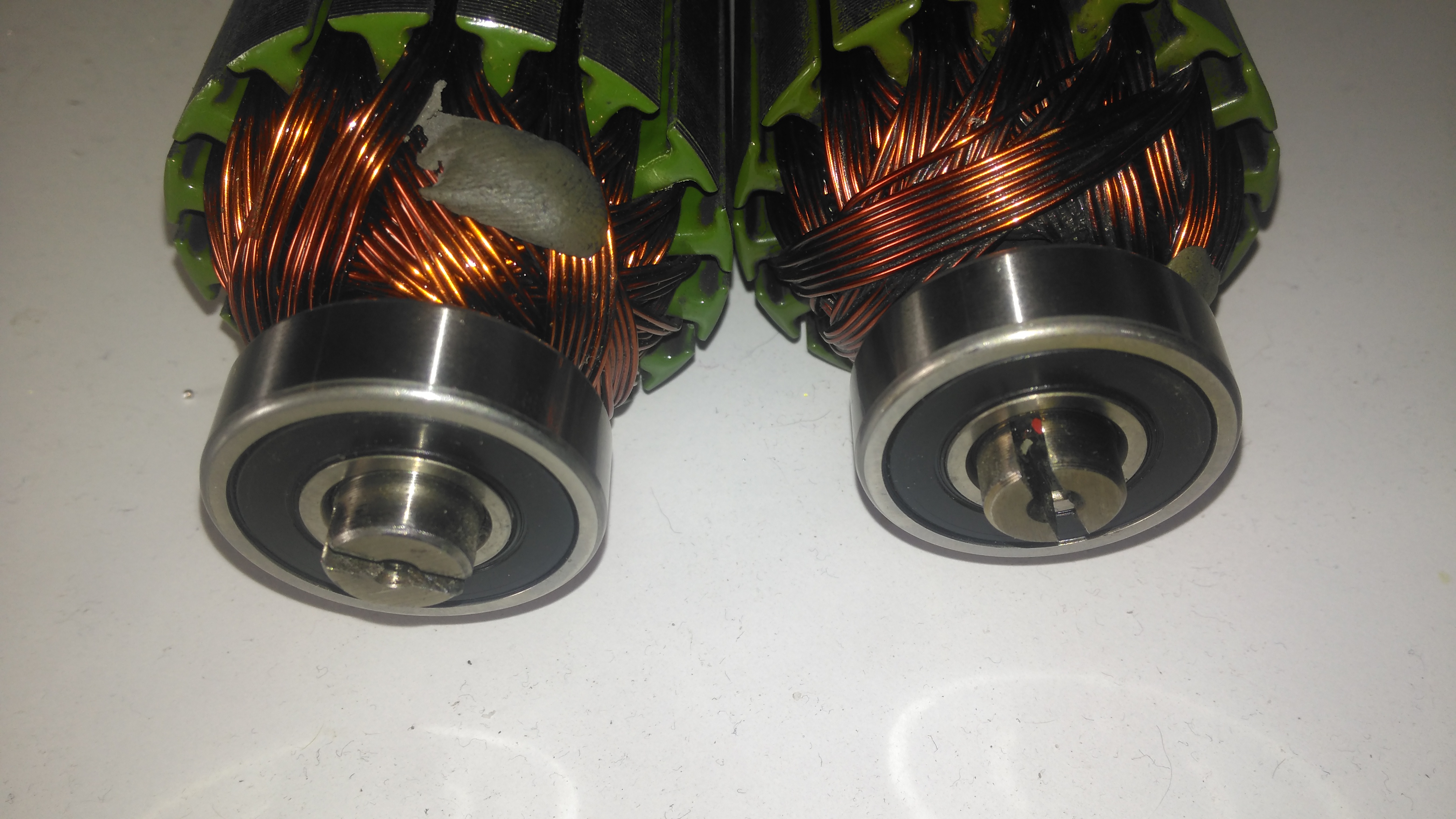
Battery Bus Links
12 5-way bus bars have been installed on the board, and 25mm² cable links them together. To get the angry pixies from the cell modules, 8mm² flexible silicone cable has been used, 4 links to a bus bar. This setup should provide more than enough current capacity.
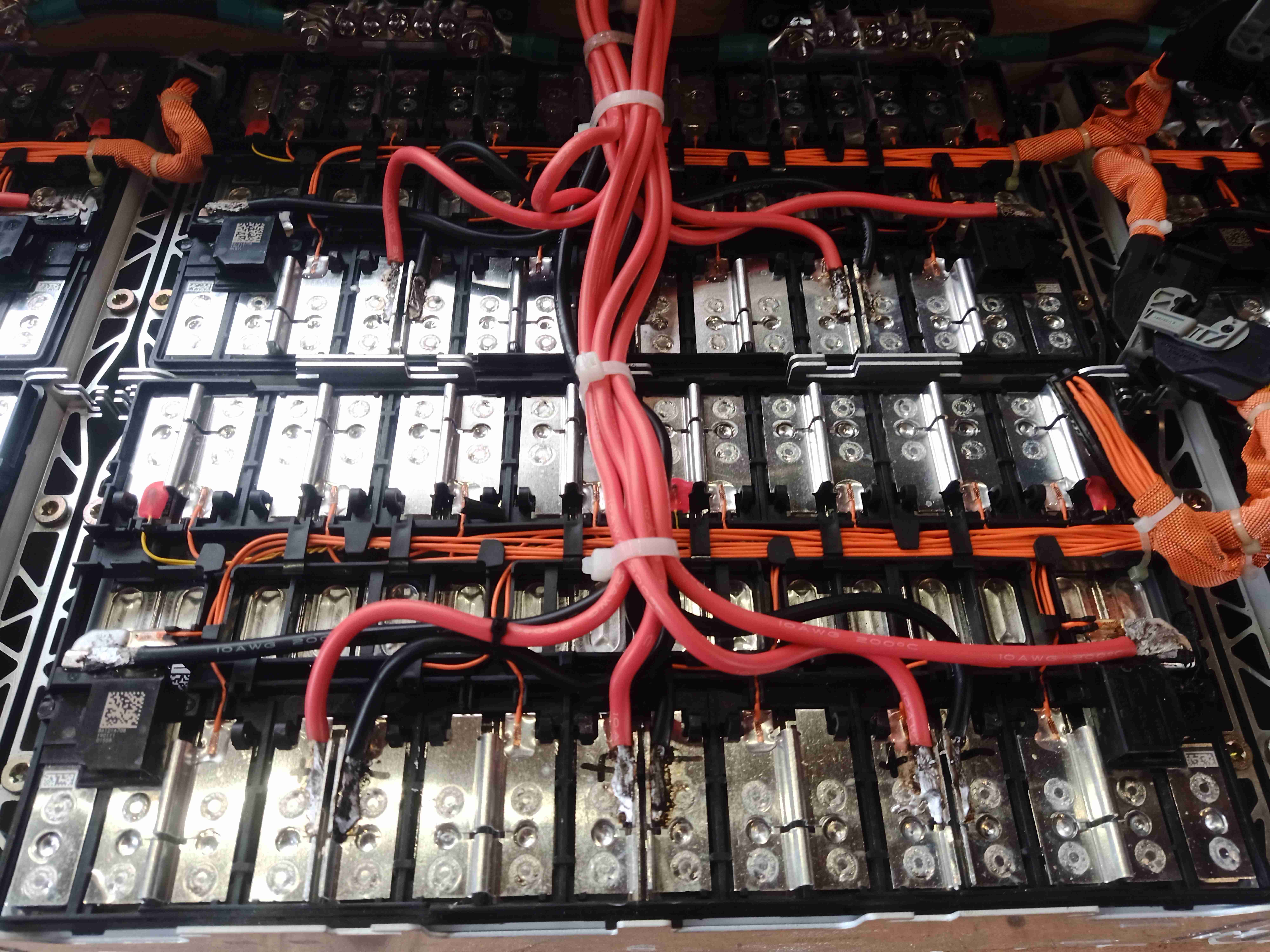
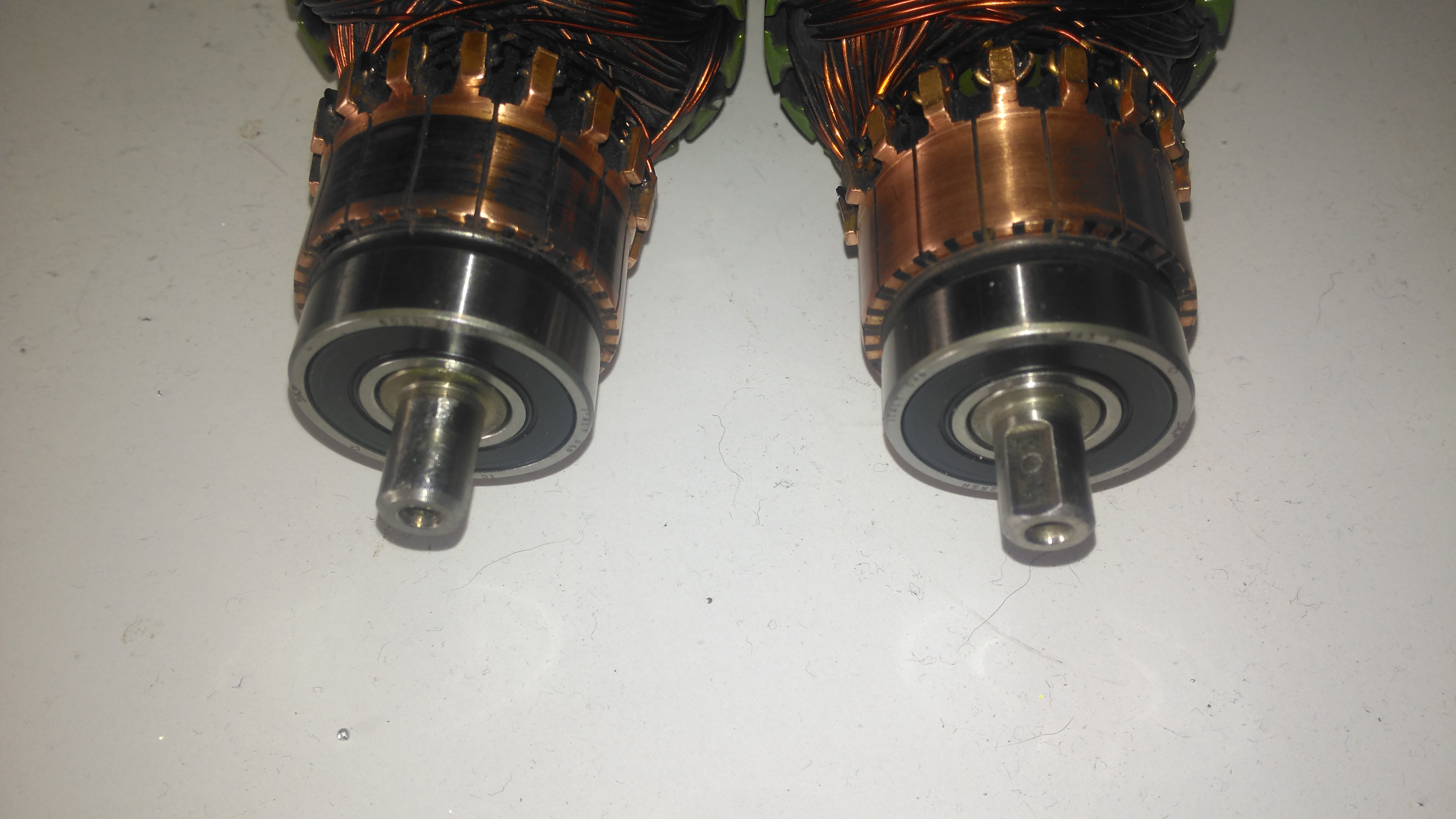
Cell Connections
Here can be seen the cell interconnects – and the grinder cuts to separate them where required to break the module up into 4S strings. As the interconnects are Aluminium, special solder was required to get the copper cables soldered down, in my case I used Alusol 45D solder, which contains a very active flux capable of stripping the oxide from the Aluminium.
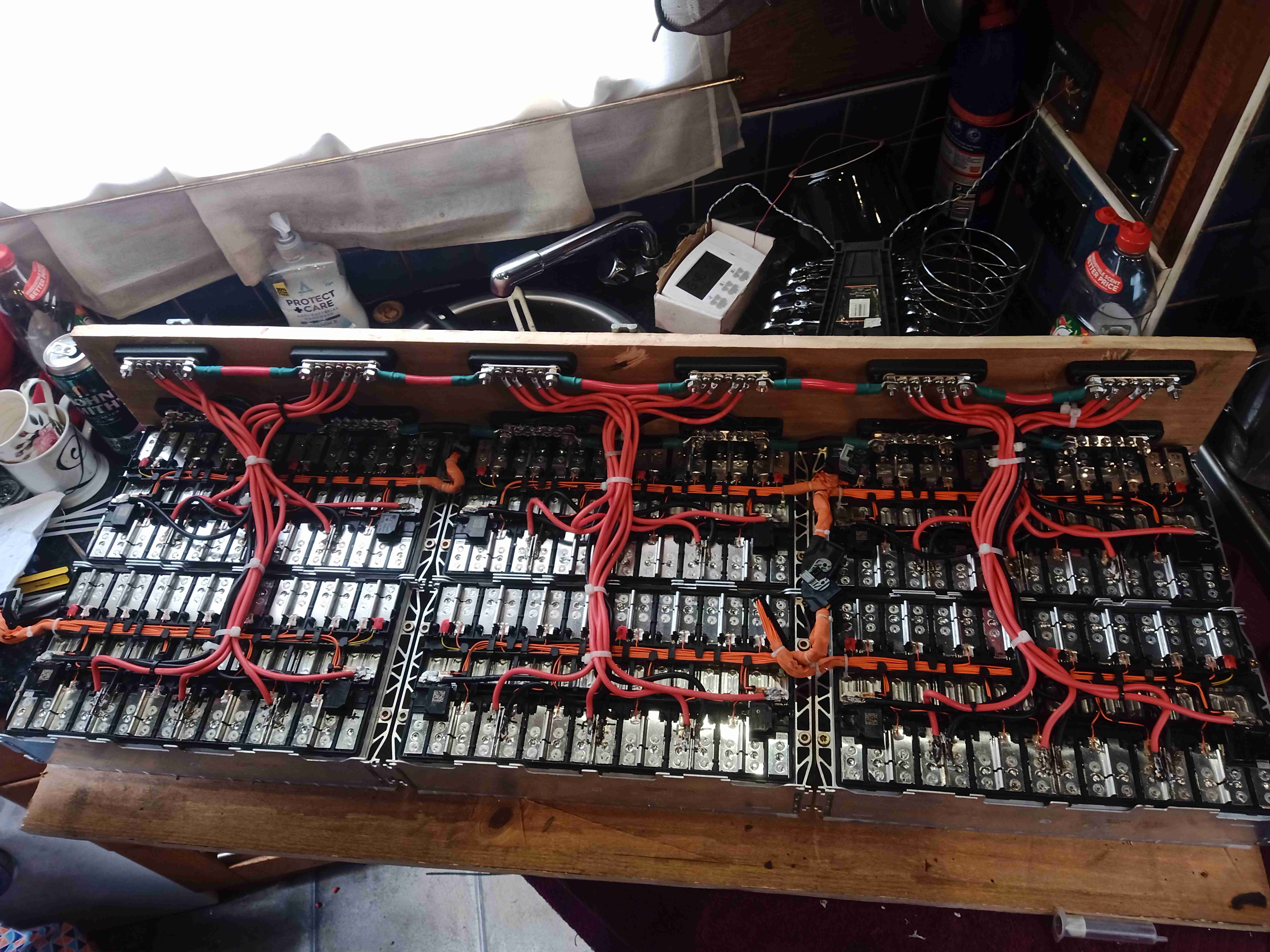
Batteries Wired
Finally, here is the new pack, all connected together. All that needs to be done now is the balance wiring loom, which will allow the BMS to sense each cell voltage individually, and connection of the BMS, Coloumeter & fuses, this will all be covered in a future post!
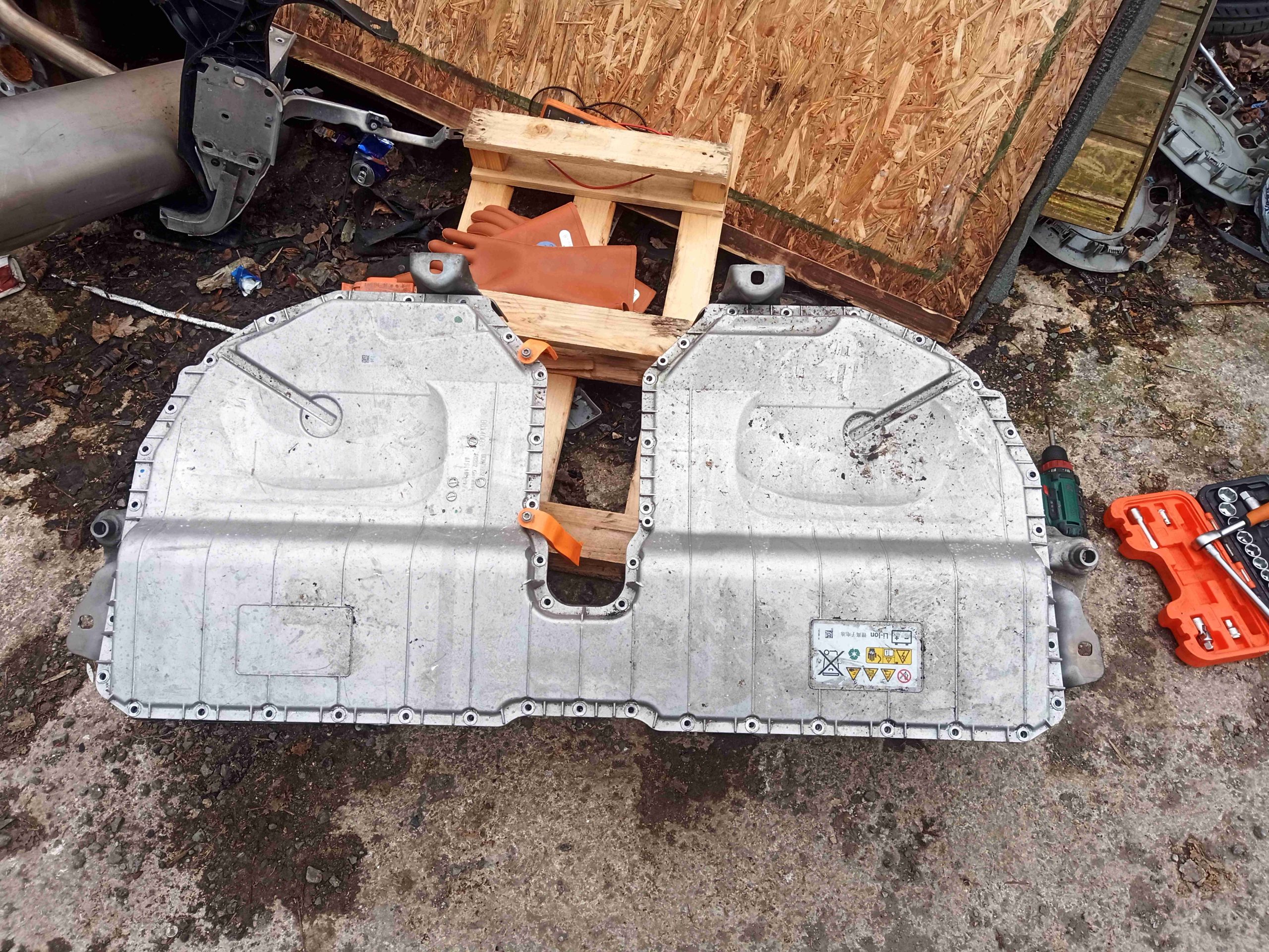
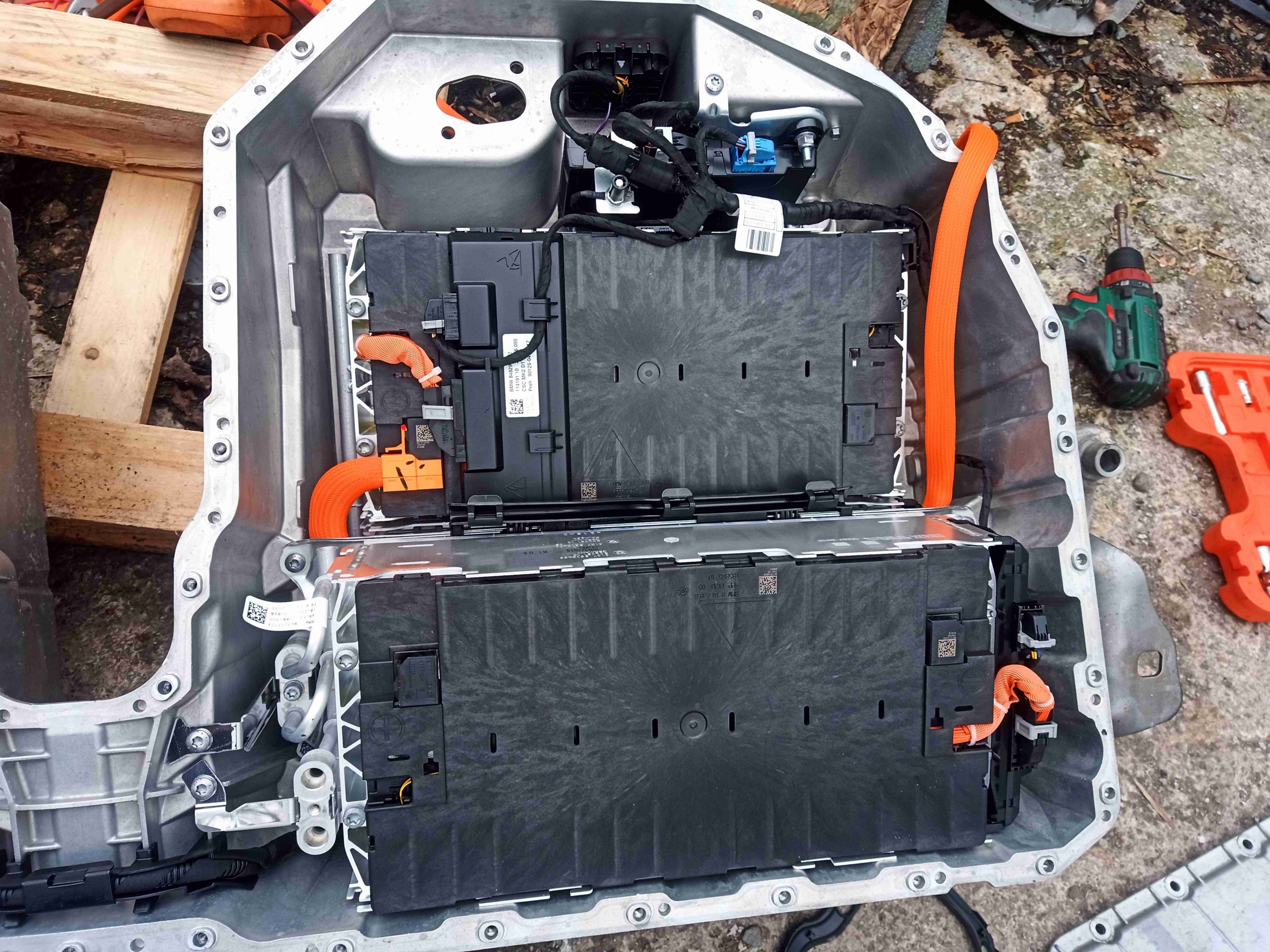
Here’s something I didn’t think I’d be doing! Here’s a teardown of a BMW 5 Series G30 530E Hybrid Battery pack – a monster 351V, 9.2kWh Lithium pack, obtained for it’s cells to replace the boat’s aging lead acids.
This is something I didn’t have the safety gear to do right of the bat – opening one of these packs is a potentially lethal exercise, with 6 unfused battery modules in series, quite capable of blowing pieces off a nice conductive sack of salt water like a person. Cue the purchase of high-voltage rated gloves for protection, just while I got the pack split into something more manageable.
Needless to say, the combination of current capacity & voltage present in EV or Hybrid vehicle battery packs is nothing short of lethal, and these units should be treated with considerable respect.
Hybrid Battery Pack
Here’s the beast of a battery. Enclosed in an aluminium cast housing, it’s very heavy, and definitely not a one-man lift!
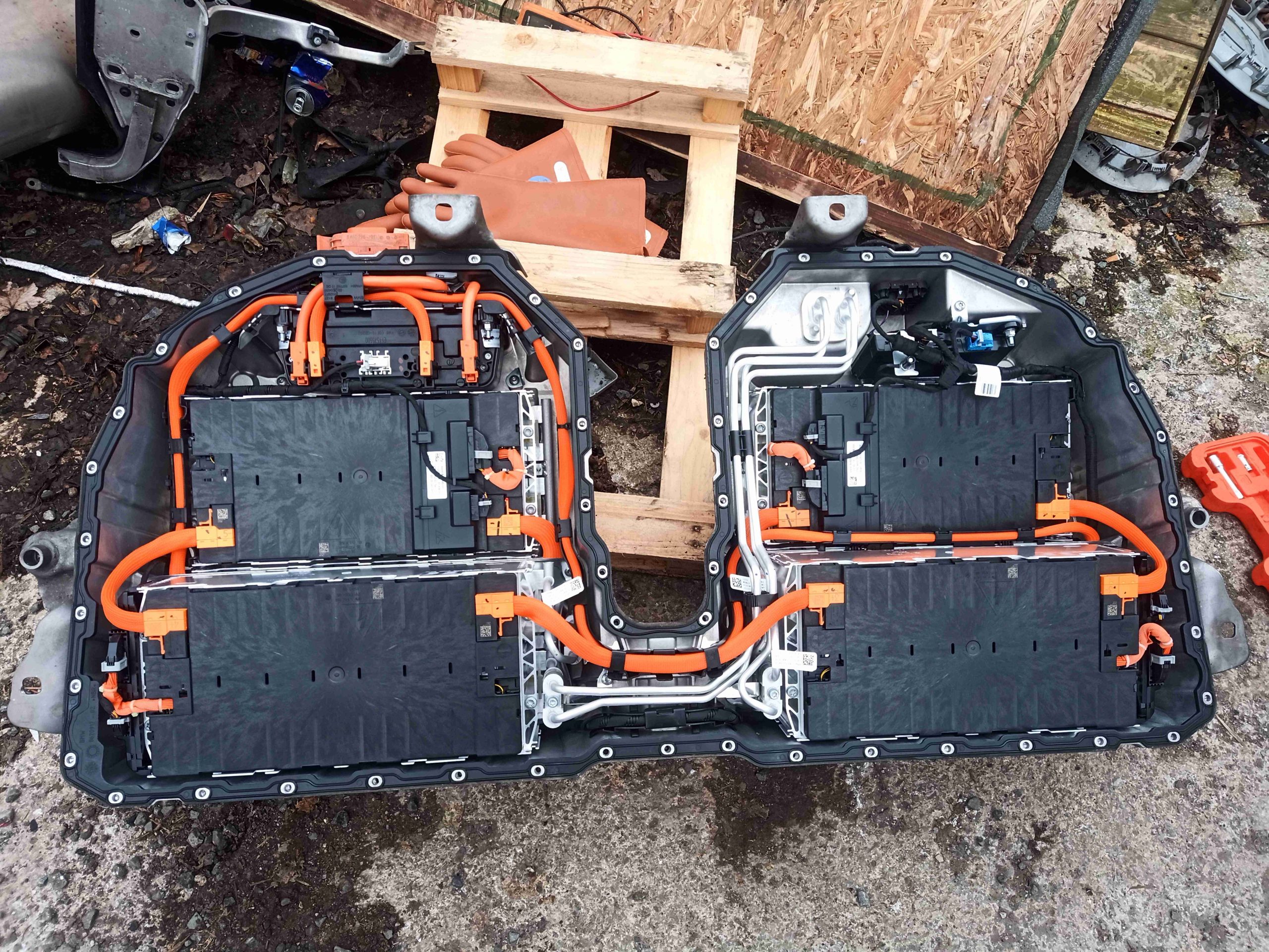
Cover Removed
After removing the top cover, secured by combination Torx/10mm hex bolts, the internals of the pack are visible. There’s no sealant on the cover, just a large rubber gasket, so this came off easily. There are 6 individual modules in this pack, all wired in series with massive links. There’s also a cooling system for each battery module, supplied with refrigerant from the car’s AC system – there’s a TXV mounted on the side of the battery pack. I didn’t see any heaters present, but I don’t know if BMW have done any neat reverse-cycle magic to also heat the modules if required using the AC system on the car.
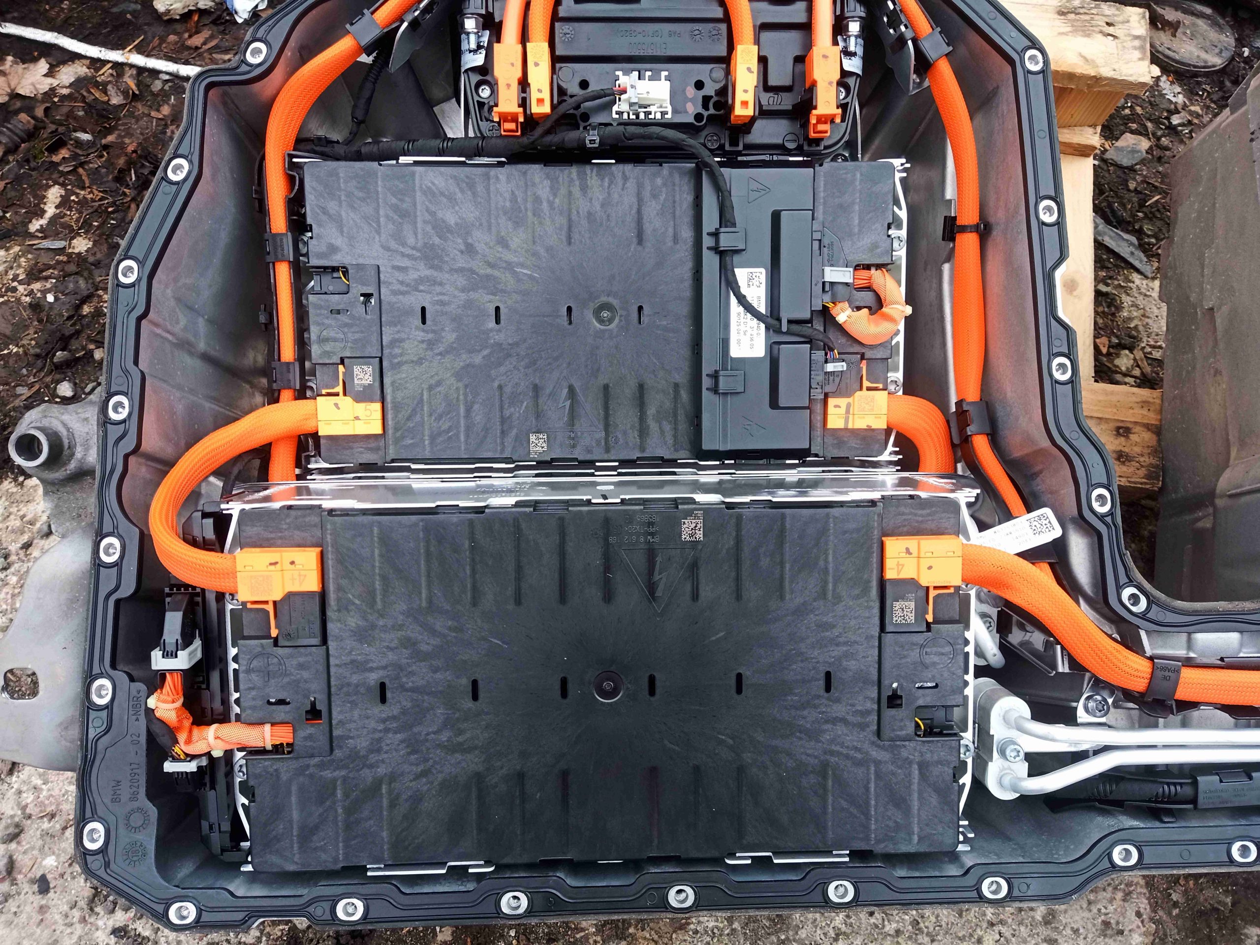
Left Side Modules
The modules are arranged 3 to a side, double-stacked at the back, then a single module at the front. The pack would normally sit under the rear seats of the vehicle, hence the unusual shape. The refrigerant lines going to the evaporators on this side of the pack can be seen in the bottom right corner.
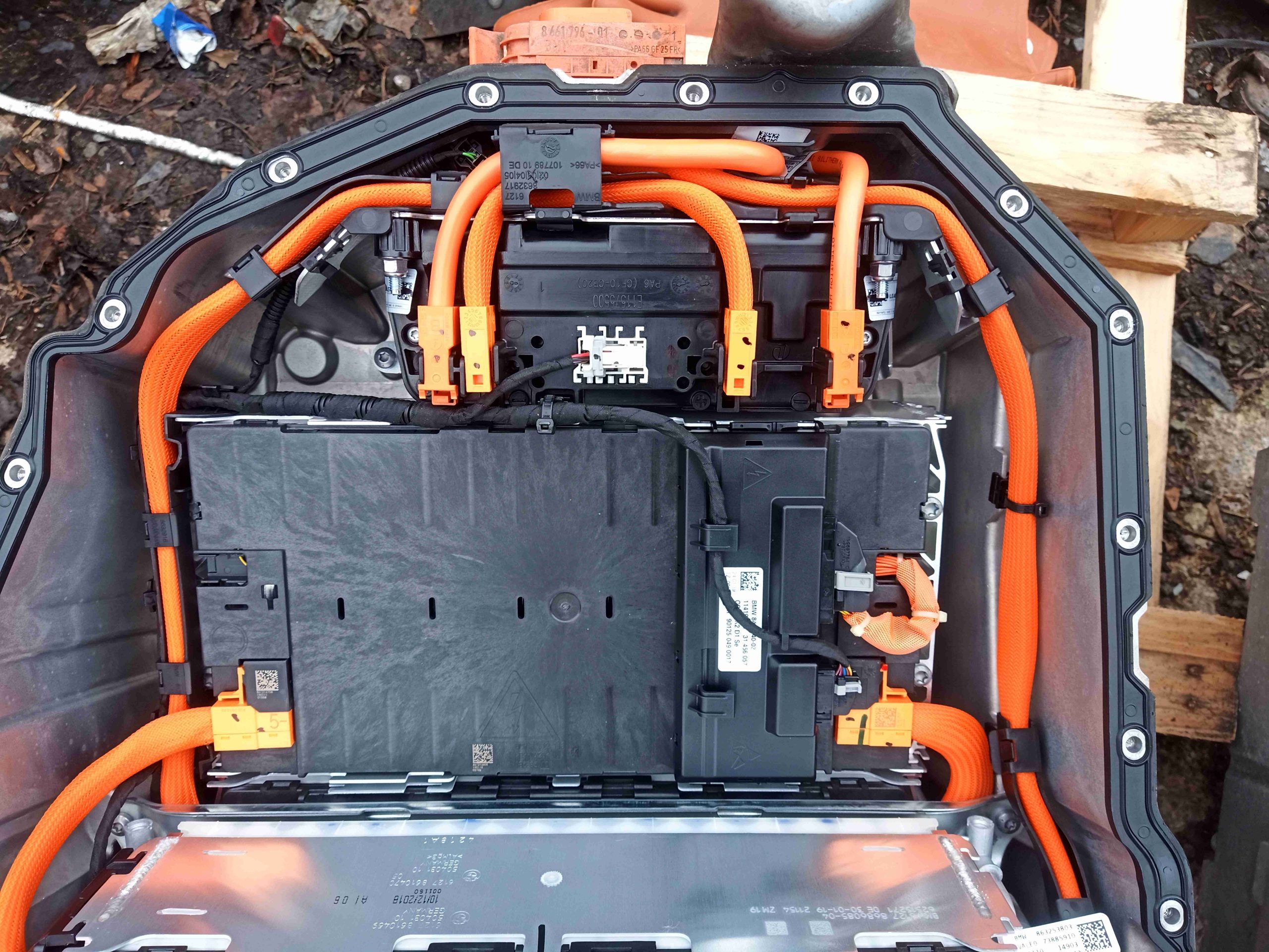
Output Cables & Contactor Pack
The main contactor pack is on the left side, just behind the massive DC output connector. I’ll dig into this in another post later on.
Right Side Modules
The right side of the pack is arranged much the same as the left, the main difference here being the battery ECU is tucked in at the top here, along with the interface connector to the car, and the refrigerant lines to the TXV on the outside, which I’ve already removed. Each module has a cell balance control unit, in this case one is mounted on the top of a module, and on the side of the module in the lower right corner.
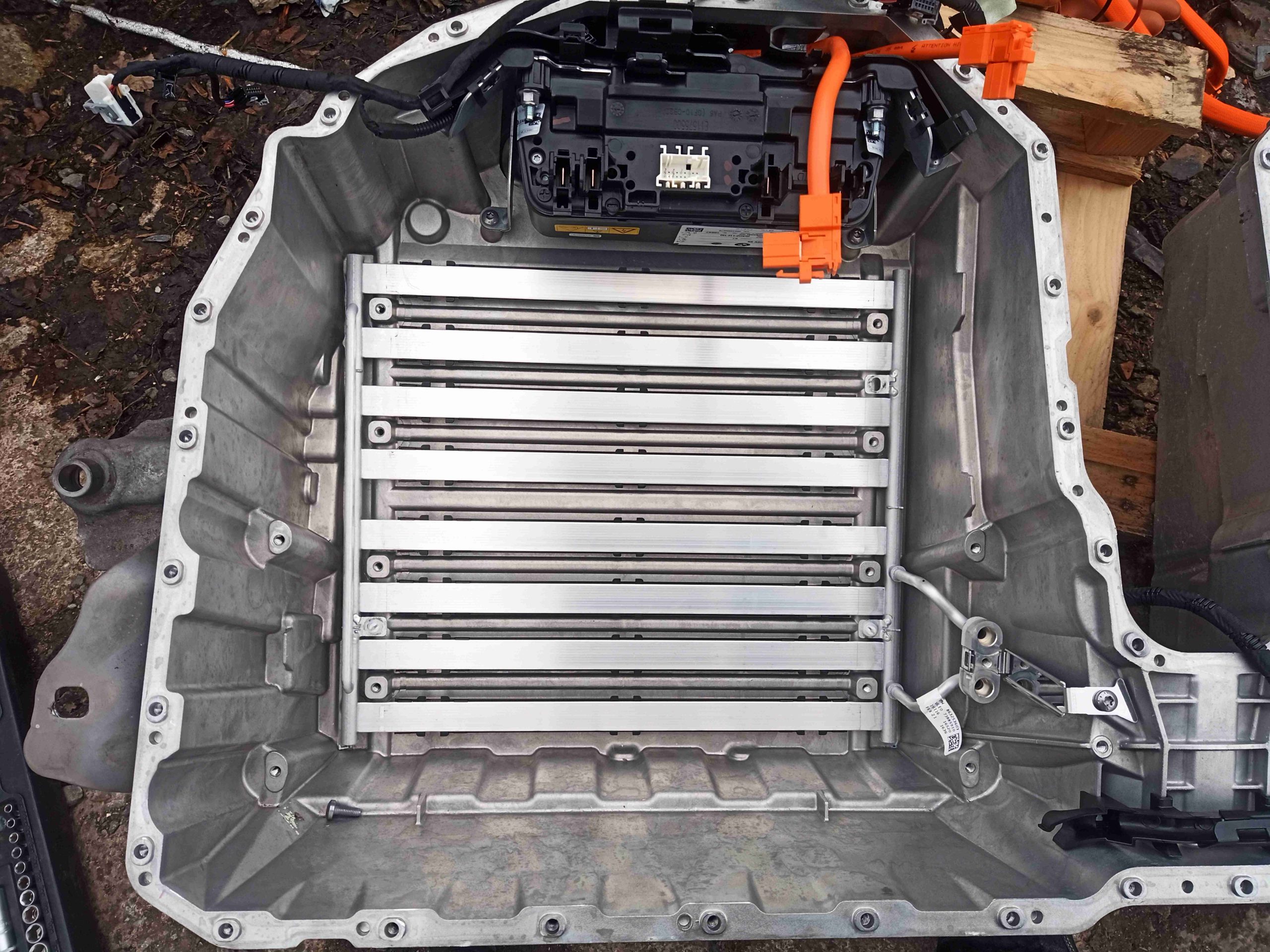
Cooling Evaporator
Once all the modules have been removed, the evaporator matrix is visible on the bottom, a series of very thin aluminium tubes, designed for the best contact with the aluminium frame of the battery modules.
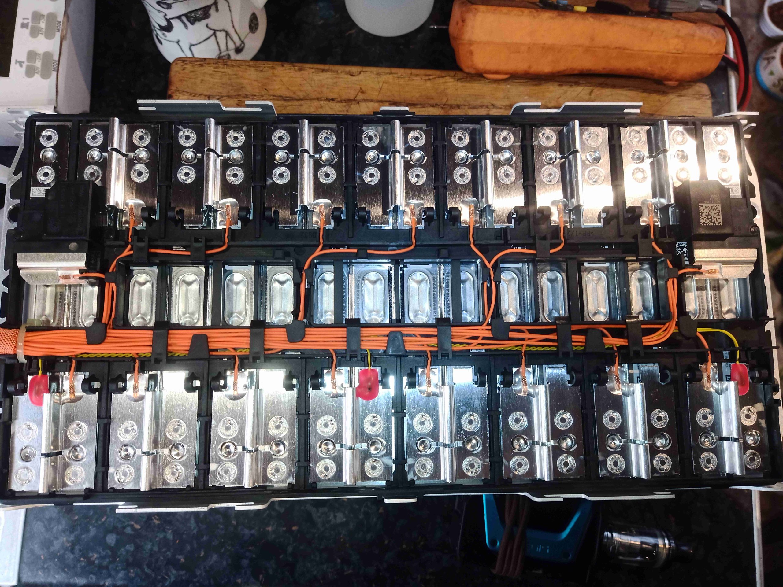
Module Cell Layout
Popping the plastic insulating cover off the battery module reveals the internal construction. I’ve not been able to find exact data on these cells, but I’m assuming them to be a similar chemistry to the ones used in the BMW i3 packs, so 4.15v Max, 3.68v nominal, 2.7v Minimum. The alloy frame itself is of laser welded construction, and there are 16 cells in series per module, giving about 58.8v per module. These will need to be reconfigured as 4 sets of 4 cells in series for 14.72v.
All the individual cell taps are nicely loomed down the middle of the module to each cell, and there are 3 temperature sensors per module (the red epoxy blobs).
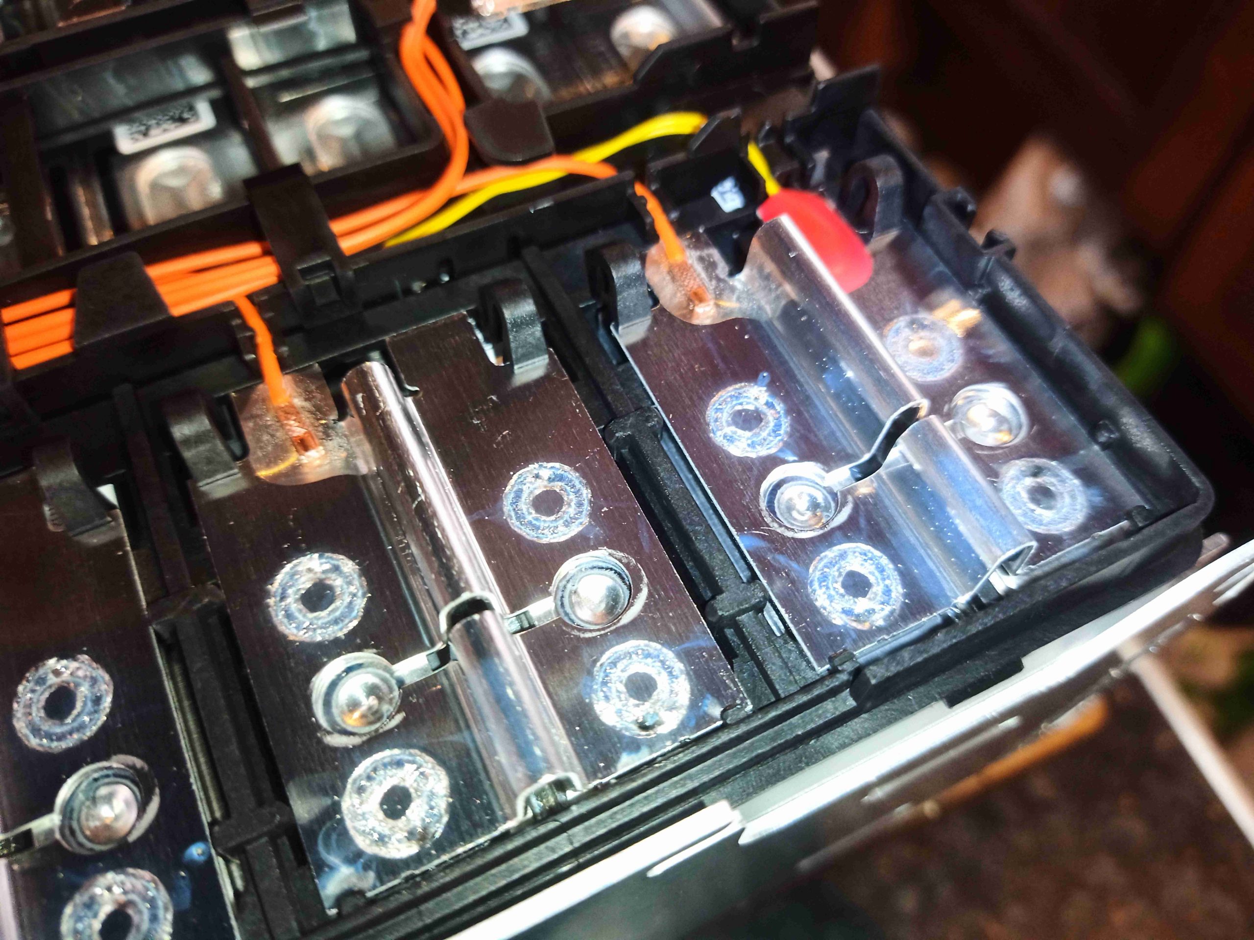
Cell Welded Links
The individual cell links are laser welded to the terminals of the cells, so this does make life a little more difficult when it comes to reconfiguring them. The links appear to be made from Aluminium, so soldering is going to be a bit more tricky than usual.
Since I do a lot of camping, and several festivals per year (when there isn’t a pandemic on!), I identified the need for a proper fridge that can be powered from my solar setup. Such fridges & coolers already exist, that run from either mains AC, 12/24v DC, and some of them (absorption cycle) will run from bottled gas.
The last option is out, as they’re hideously inefficient, and this would require the carrying around of a flammable gas source. Ready-made units using the vapour-compression method used in all domestic & industrial refrigeration, but they are very expensive. For an upright fridge type unit that could store enough to feed a family of 4, I was looking at over £550+VAT. A cheaper option was definitely required.
Since I already have a couple of spare Danfoss BD35 DC refrigeration compressors, I decided to grab a cheap domestic mini-fridge, and perform a compressor-ectomy to make the unit operable on a low voltage supply.
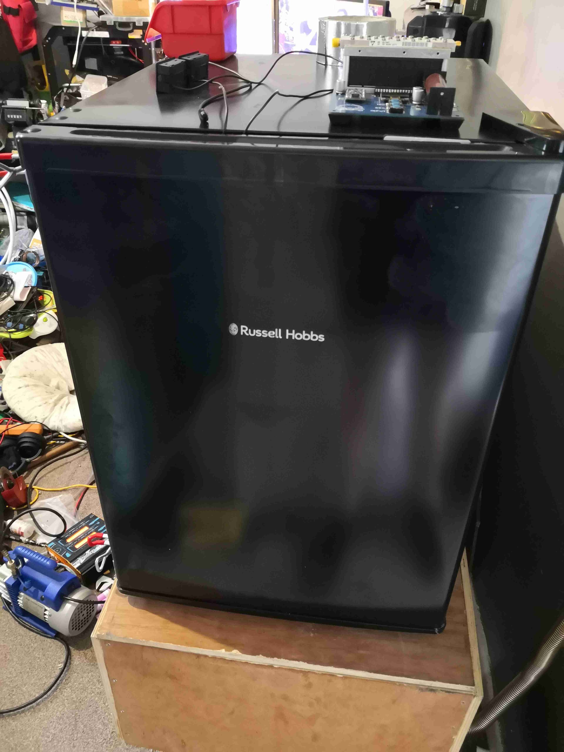
Russel Hobbs Mini-Fridge
Here’s the fridge I obtained from one of the many suppliers of domestic kit, this is a Russel Hobbs branded mini-fridge.
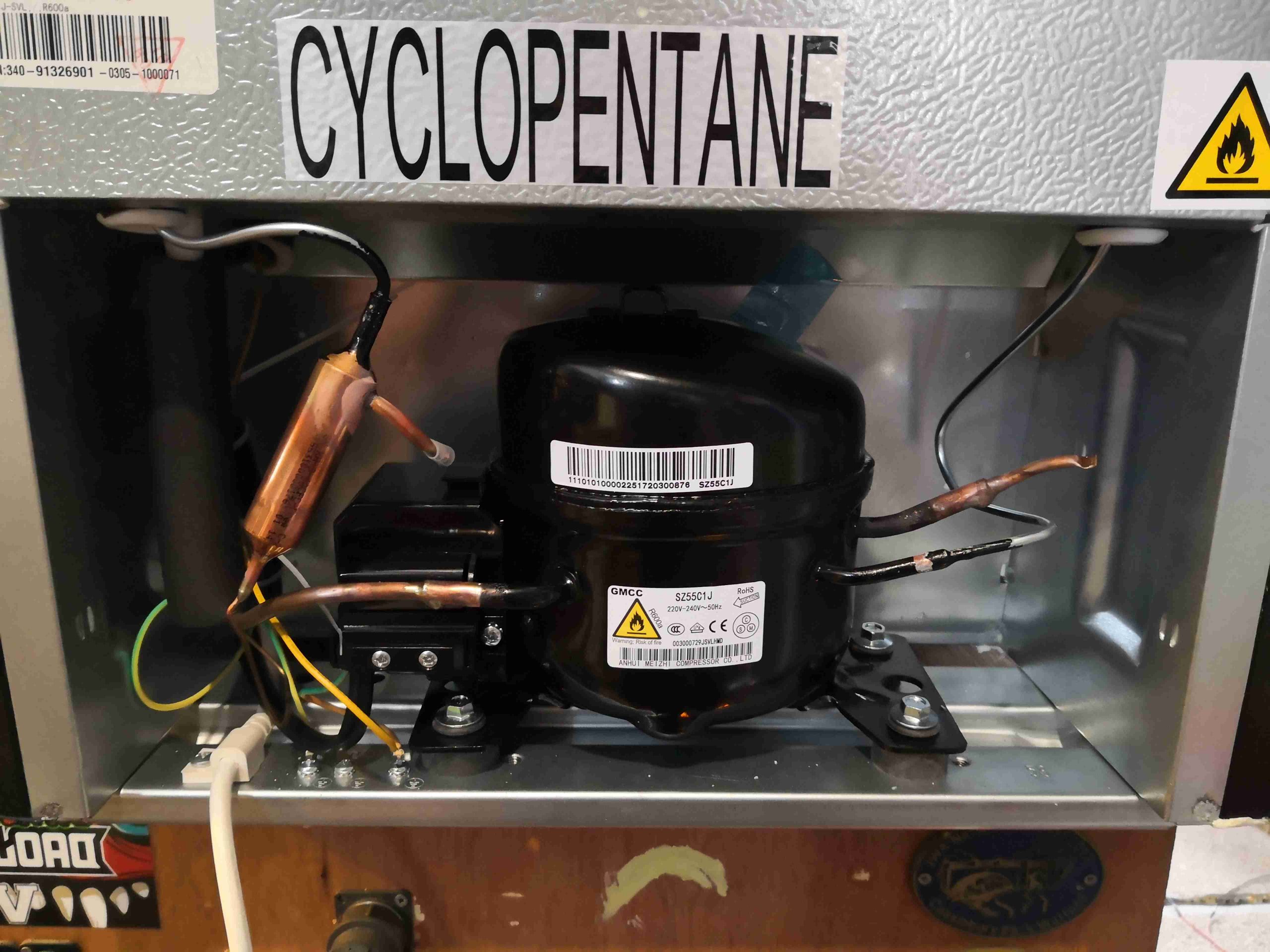
Factory Compressor
I was careful to select a unit with no Aluminium pipework – the stuff is damn near impossible to join onto with soldering. Brazing is impossible due to the temperatures involved. These units have copper & steel in their circuit, so this will be easy. Factory charge is 16g of R600a (Isobutane). This one isn’t even going to make it to the point of being plugged in before modification!
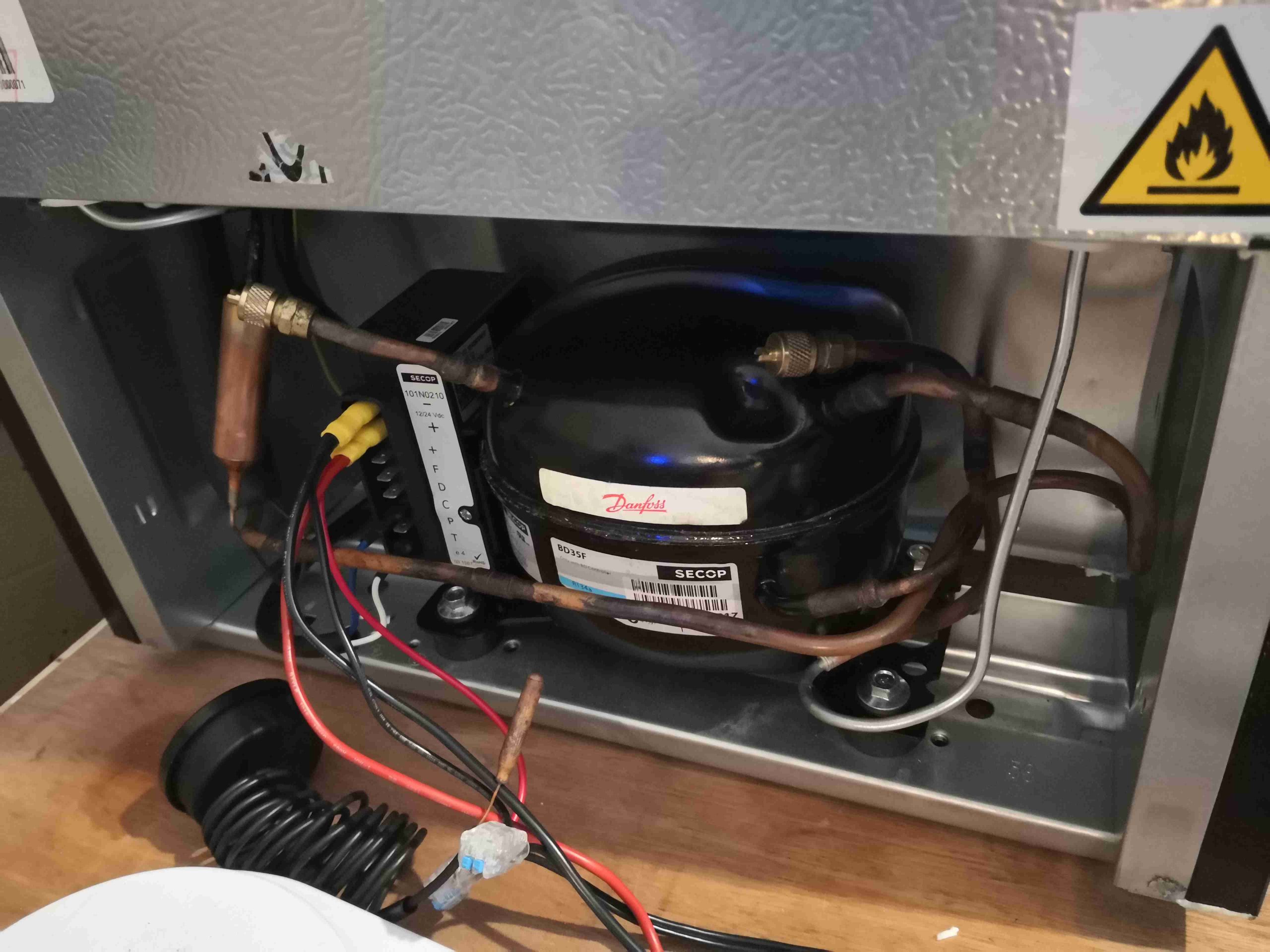
BD35 Fitted
I evacuated the factory charge, and removed the original compressor. To avoid having to disturb the capillary tube, I ensured the system was in continual nitrogen purge to keep moisture out – this meant I could retain the factory filter-drier. The condenser in this fridge is skin-type, on both sides of the outer shell, and formed from steel tube. This connection required the use of silver braze to connect to the compressor.
The suction line from the evaporator is copper, so that’s an easy braze onto an extension to the compressor.
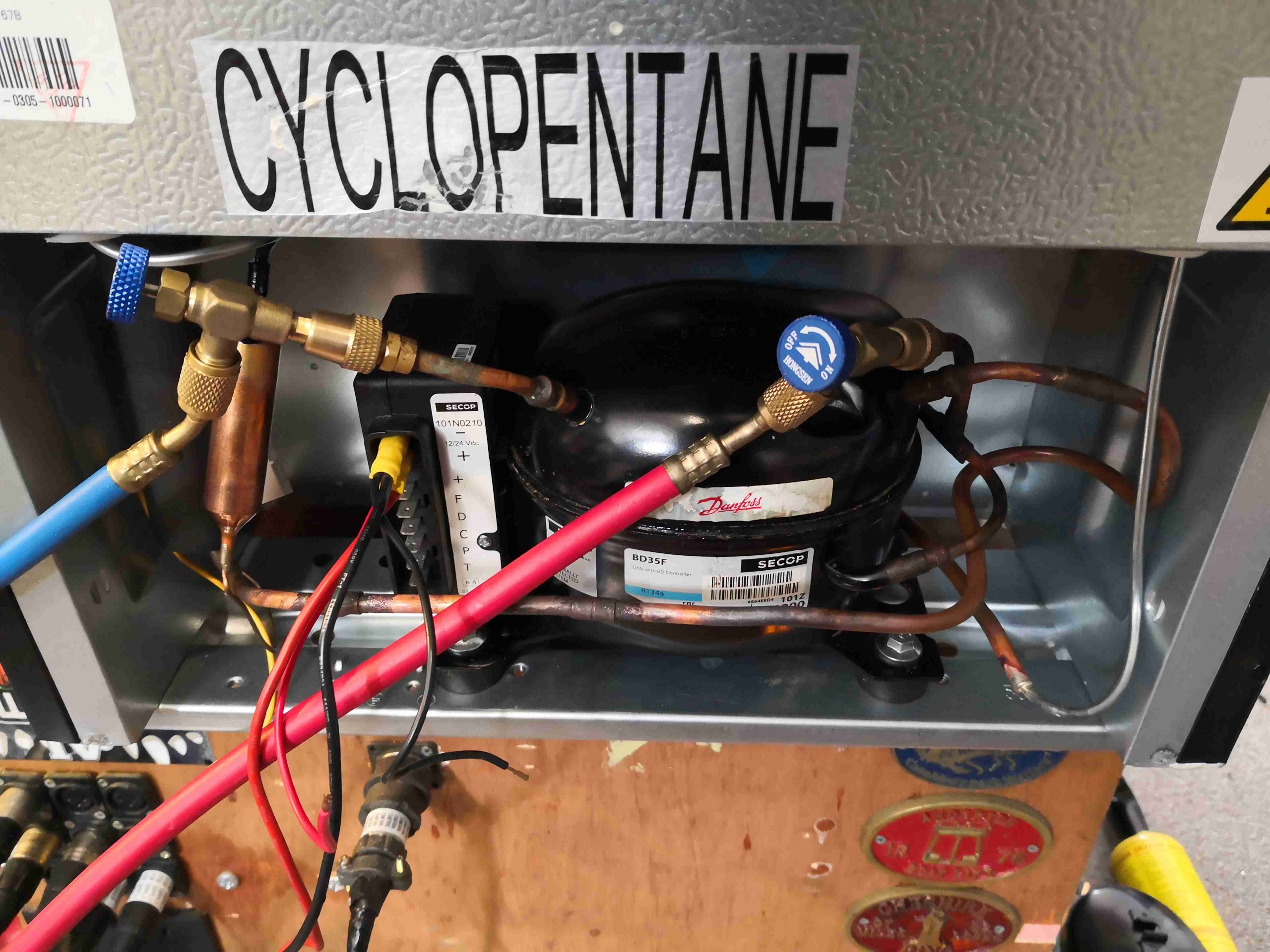
New System Charging
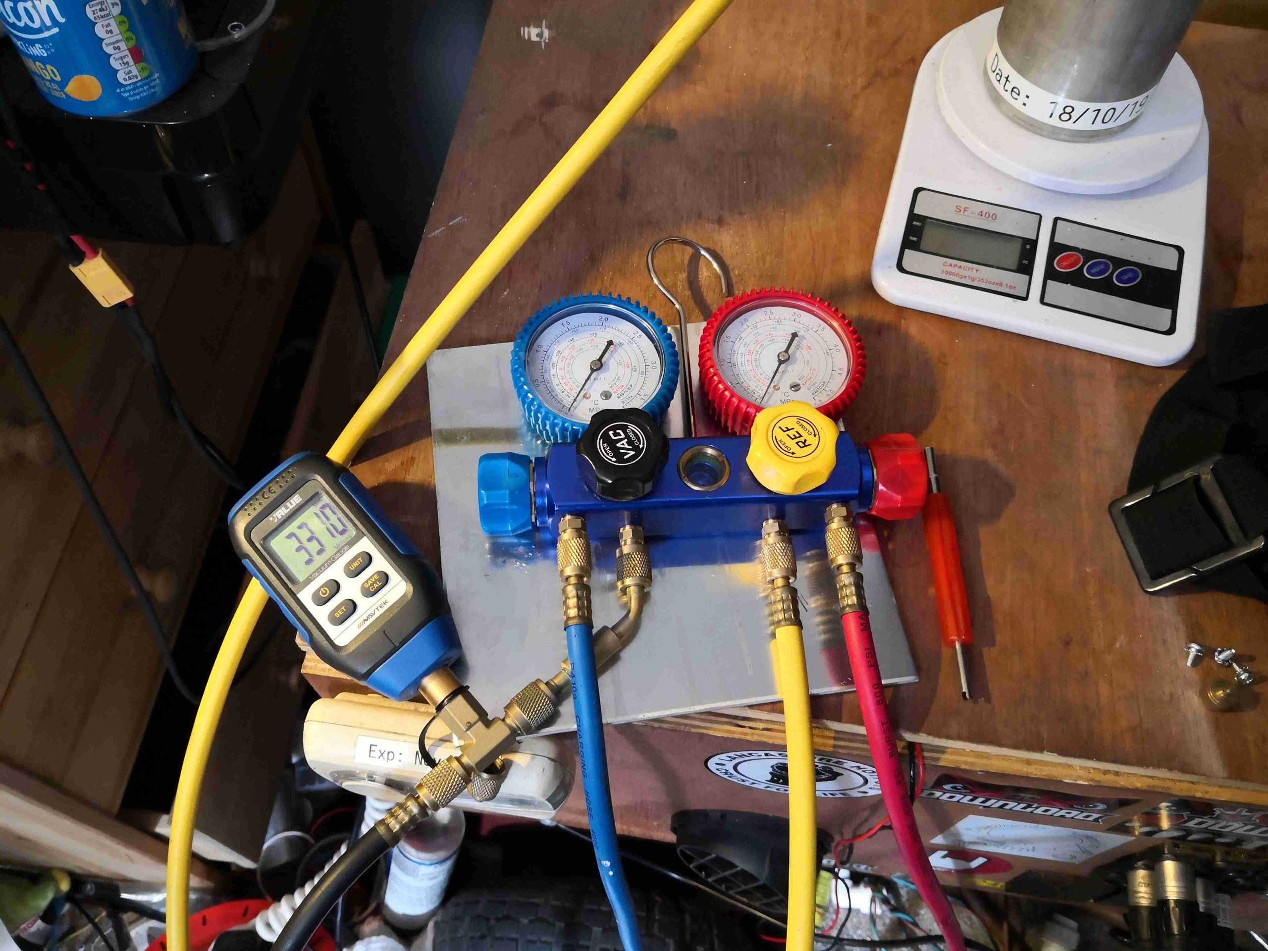
Once the new compressor was brazed into place, a full leak & pressure strength test is performed. I’m using isolation valves on the charging hoses here – they’re quite nifty. Backseat them all the way & the charging hose is isolated from the system. Front seat all the way & the hose valve is opened, and the Schrader valve core is depressed in the service port. They really cut losses when charging systems with Schraders!
Vacuum Stage
Next step is applying a vacuum to the system. I aimed for a final vacuum of 250 microns. This by far takes the longest amount of time in a refrigeration job. For reliability & longevity of the system, it’s imperative that all contaminants such as water vapour & air are removed from the circuit.
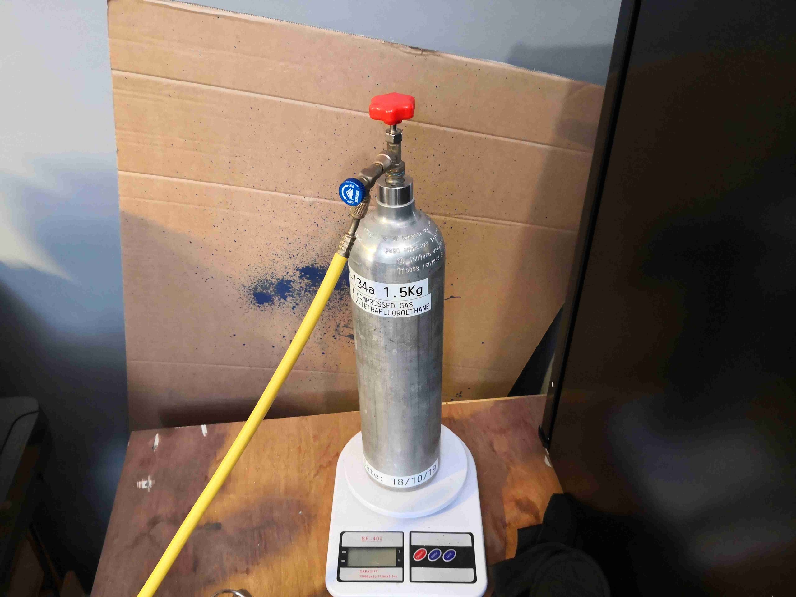
Refrigerant Bottle
The final step is a refrigerant charge. Since I’m not at all fond of flammable refrigerants in this use case (camping), I broke out the bottle of R-134a. This isn’t ideal, as the capillary tube will be sized for the original charge of R600a, but the effect on efficiency shouldn’t be too terrible. (There will be a drop in COP, but I haven’t yet measured the actual COP of the re-engineered system). Unfortunately, as this uses a plate evaporator with a built in capillary tube, there’s no way to resize this for another gas. The capillary tube is fed down the centre of the suction line in these systems, to increase efficiency of the cycle.
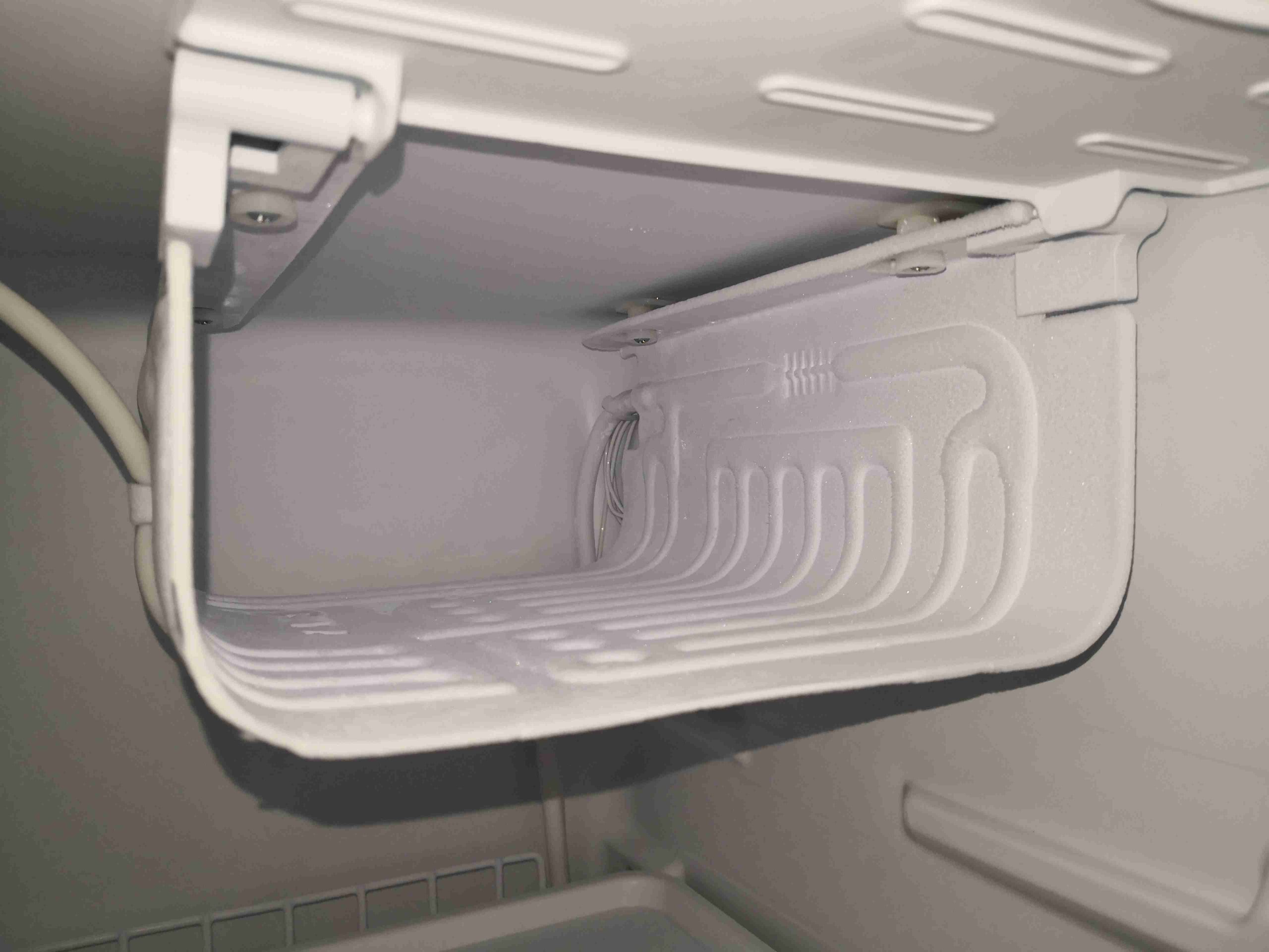
Evaporator
A few minutes after an initial charge of 45g R-134a, there’s frost on the plate evaporator! Since this is a gas change as well as the compressor, there’s no other way than to charge slowly, and wait for the system to stabilize at temperature. Then gas is added until there’s an even frost all over the evaporator surface. I would have measured the charge by suction line superheat, but I have no idea of the original system specifications.
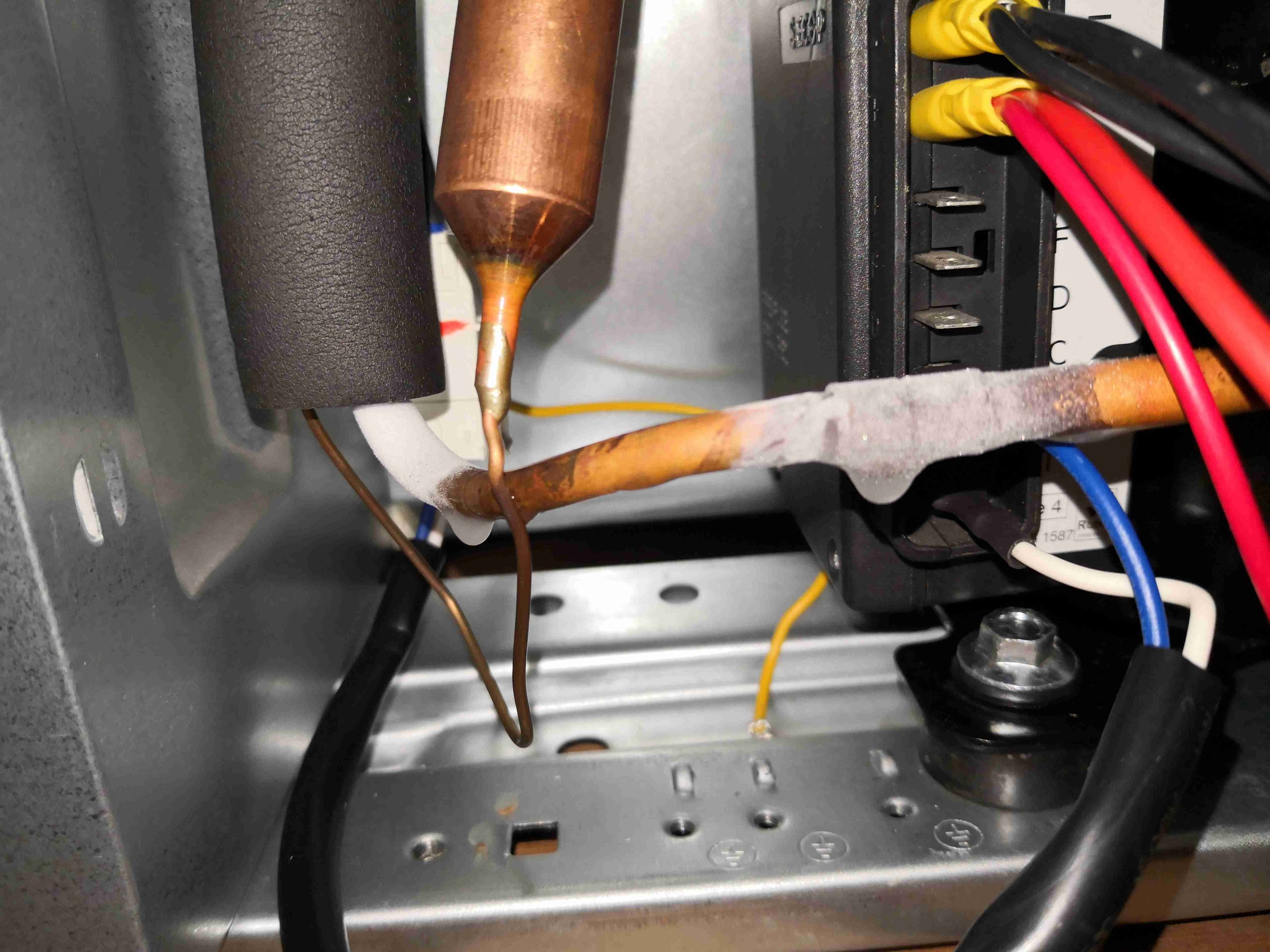
Suction Line Icing
In this case, when running the cabinet down to the minimum temperature possible, a slight overcharge became evident. Releasing a small amount of the refrigerant back into the charging bottle sorted this out.
I may yet make another modification to this unit, to remove the skin-condenser from the circuit. While cheap, and difficult to damage as they’re buried behind the outer case metal, they’re not very efficient. I have some small fan-cooled condenser coils that will probably end up in the back next to the compressor to improve efficiency. This will also take some of the heat load off the cabinet insulation, as there won’t be a coil of hot refrigerant next to it.
Recently I found the need to do some measurements on 75Ω CATV equipment, only having 50Ω test equipment to use. For this, matching networks exist to convert 50Ω to 75Ω, but they’re fairly simple, so building them was a viable option.
Matching Pad Schematic
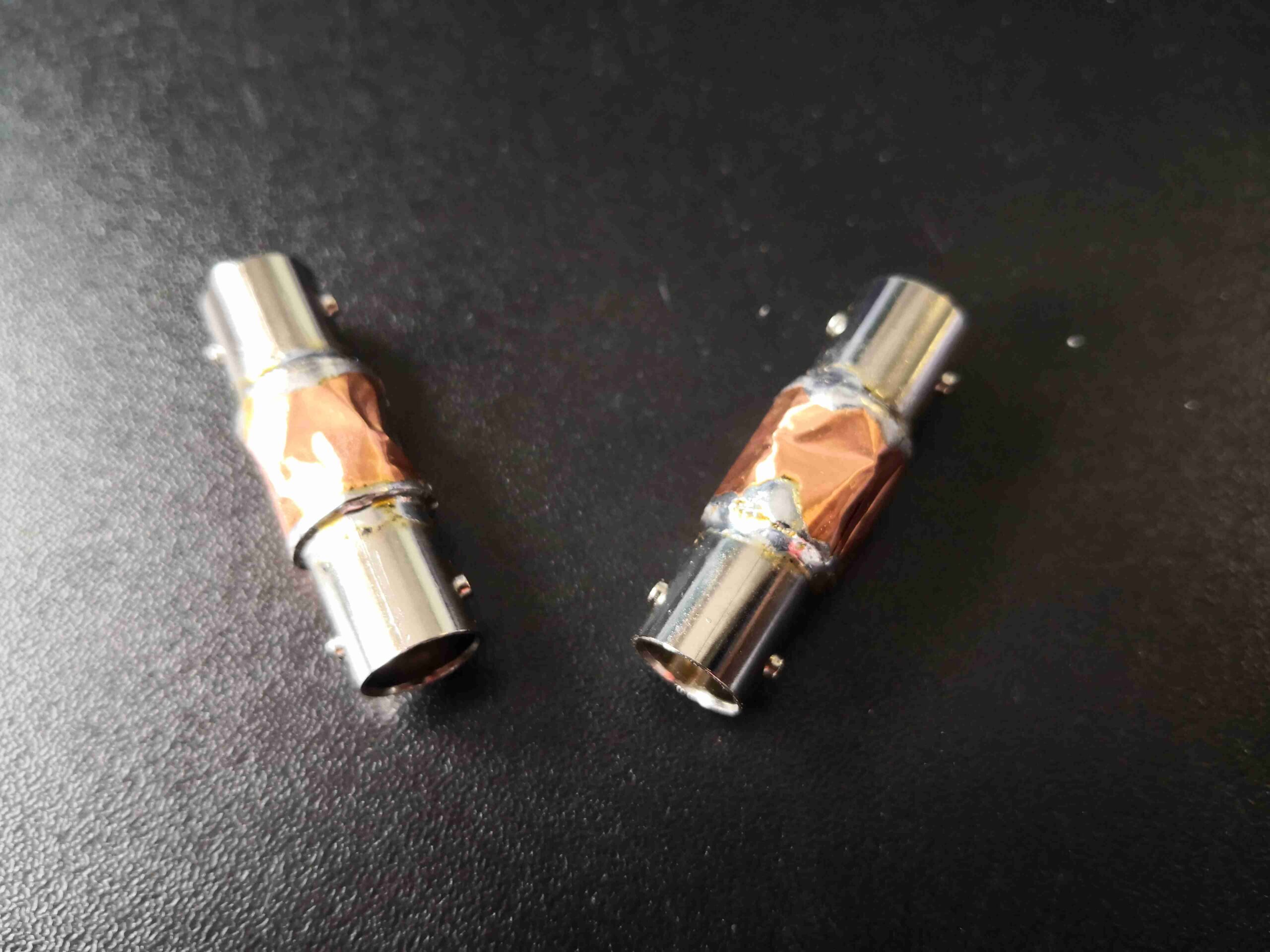
Above is the very simple schematic to create the 75Ω match. To help keep any parasitics down, this circuit will be built directly onto the back of BNC connectors, that are soldered back-to-back, before being covered in shielding tape.
Resistors Soldered
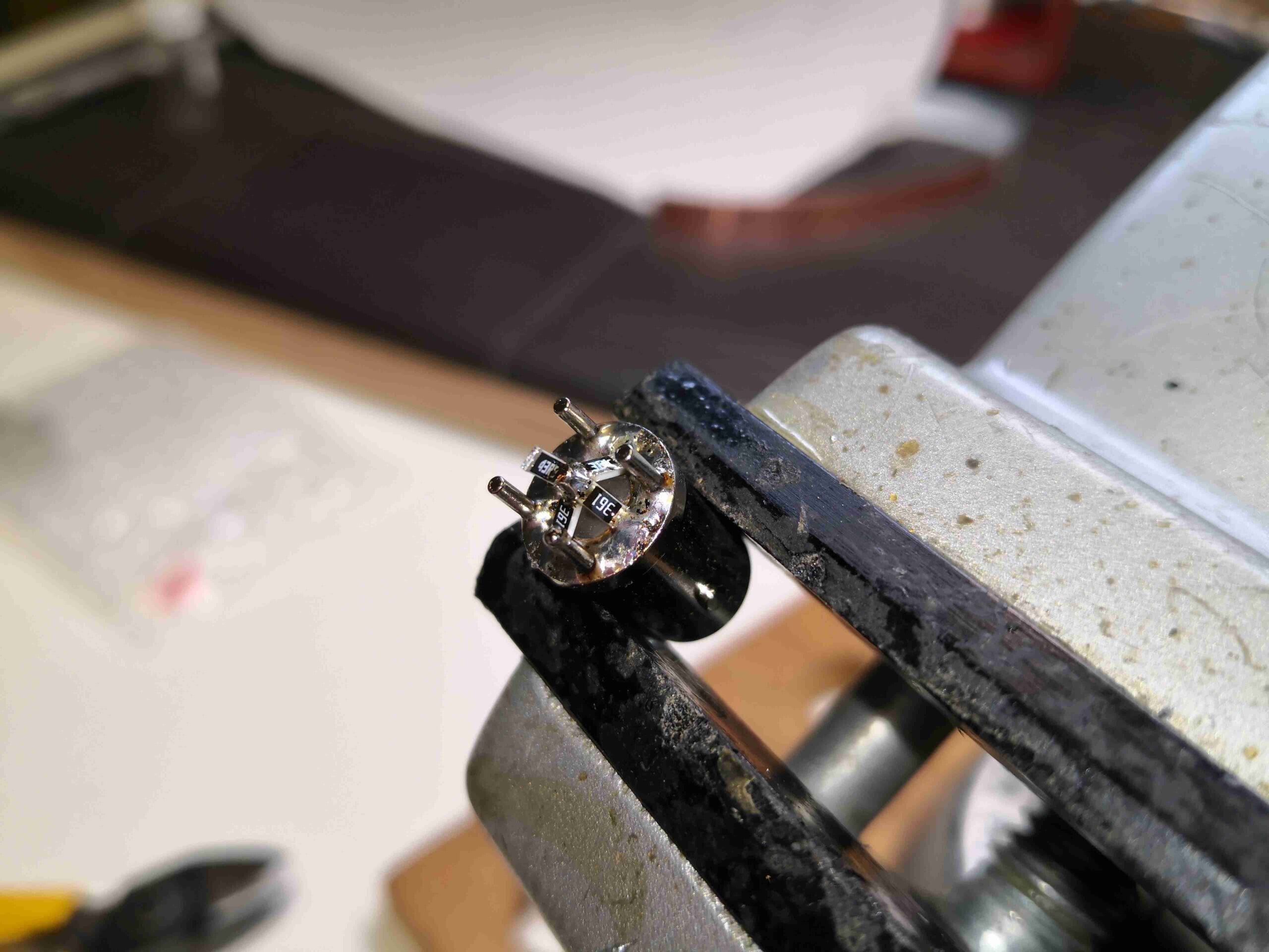
Here’s the first 50Ω BNC connector, with the resistor network soldered on. I’ve used 4x 360Ω resistors in parallel to create the 90Ω to ground, and a single 43Ω series resistor on the centre pin.
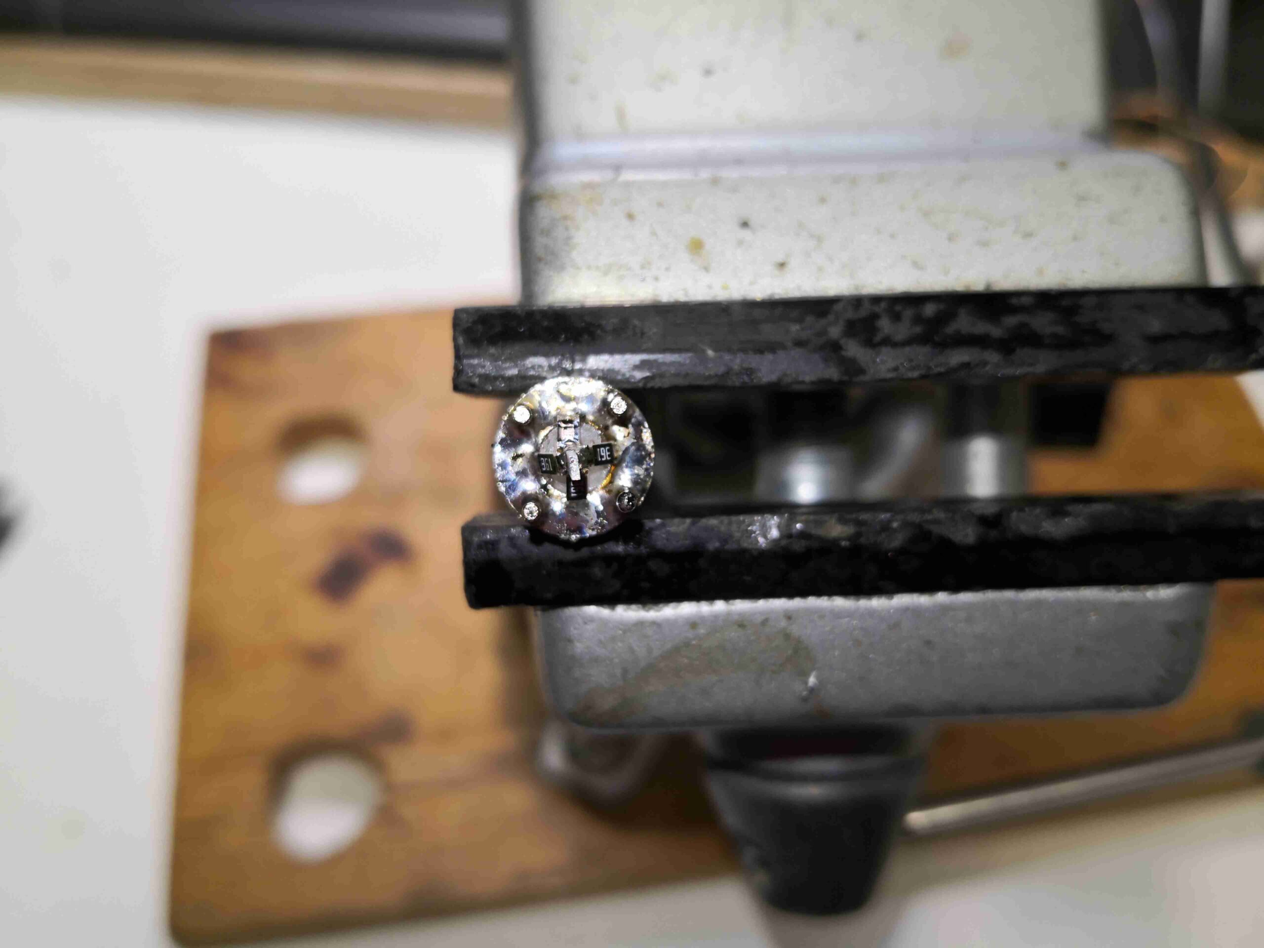
End View
This end view of the arrangement shows the 4 resistors evenly spaced around the centre pin & soldered to the shell.
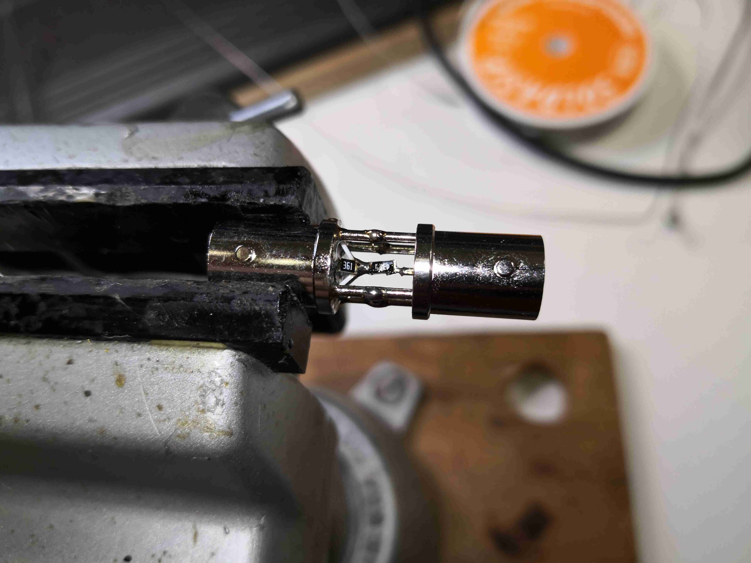
BNCs Soldered
The centre pin of the 75Ω BNC connector is trimmed down to match the length needed to touch the end of the series resistor, and it’s soldered in place. It’s a bit tricky, soldering within the gap between 2 of the ground pins!
Completed Matching Pads
Finally, the internals are shielded with copper tape, soldered at the seams.
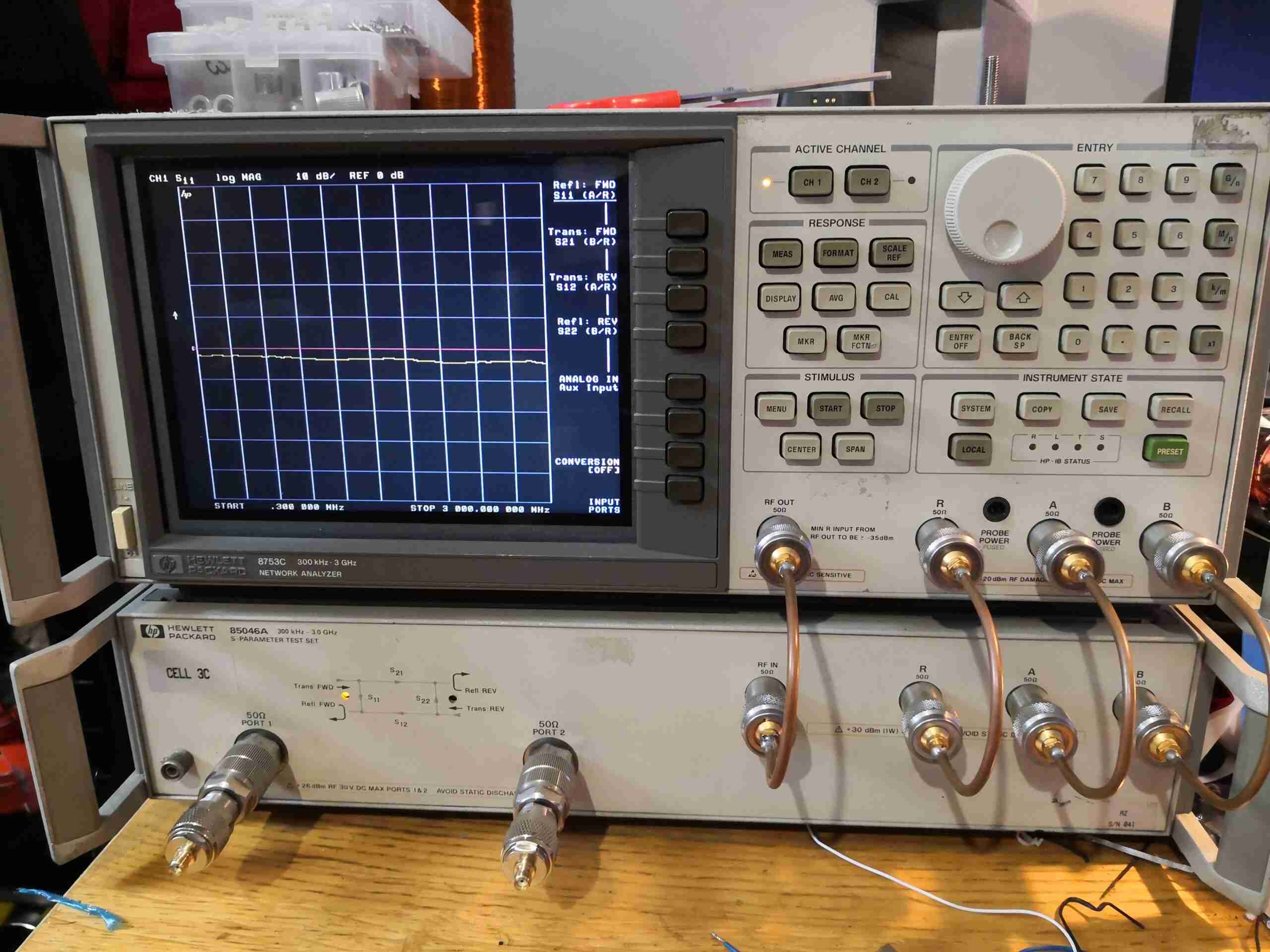
Since I inherited an old HP 8753C Network Analyser from work, I figured updating a few things to relatively modern standards would be good. The factory CRT, being 28 years old, is definitely getting a little tired, not to mention being slow to warm up. I read over on the EEVBlog forums about a DIY modification to integrate an LCD display into place instead. There was also the option of a ready-made kit for these instruments which would integrate an LCD, but the cost at over £300 was very prohibitive!
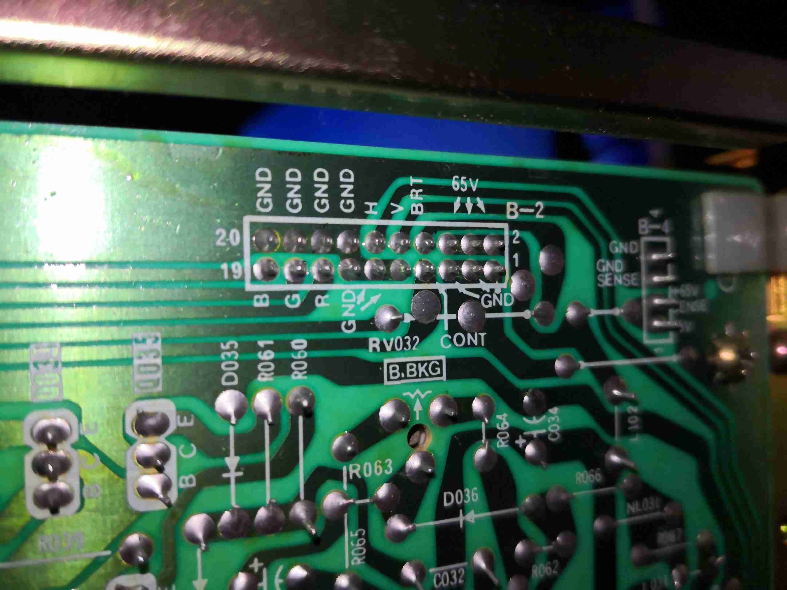
CRT Pinout
The CRT display unit is a self-contained Sony unit, taking RGBHV signalling from the graphics control card of the analyser. Power is 65v DC which will definitely come in handy for powering the new LCD & control gear, after some conversion.
Test Wiring
Doing a quick test with some wiring stuck into the video connector from the graphics controller, proved that I could get a decent video signal out of the unit! The only signals used here are RGB, along with the vertical & horizontal sync.
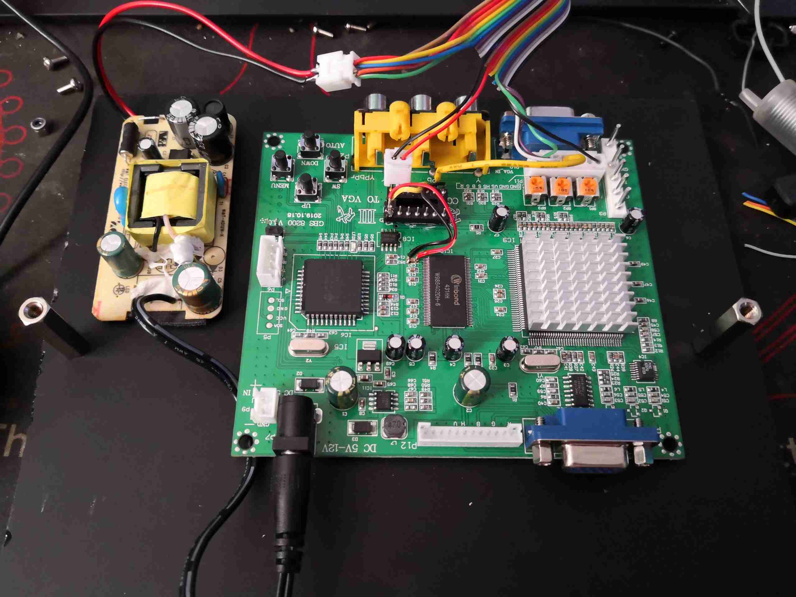
GBS-8200 Converter Board
The video is converted to VGA by way of a GBS-8200 arcade machine video conversion board, which will take many different video formats & spit out standard VGA signalling. The power supply to the left is a standard 100-240v to 12v PSU, which is happy to run at 6t5v DC input voltage, albeit with a ~5 second delay on output startup when power is applied. This is due to the massive 6.6MΩ resistance of the startup resistor chain, which I did reduce by 50% to 3.3MΩ with no effect. Since it does start OK even with the delay, I think I’ll not tinker with it any further. I doubt I could pull the full rated power from it with such a low input voltage, but all included, this mod draws less than 600mA at 12v.
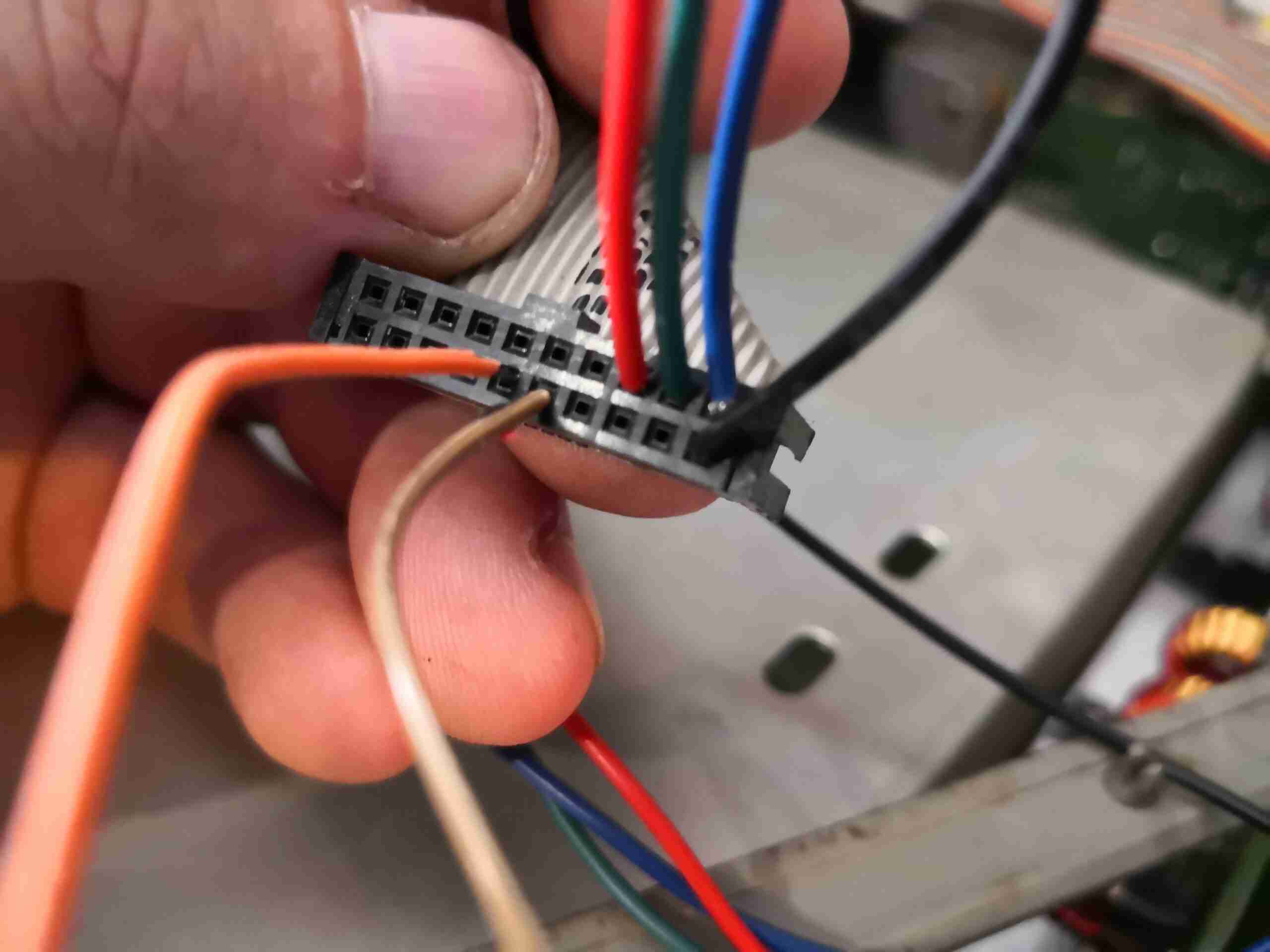
A custom 20-pin IDC cable was made up to connect to the analyser’s graphics board, and this was then broken out into the required RGB & sync signals. Quite a few of the grounds are unused, I’ve not yet noticed any issues with EMC or instability.
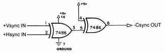
Sync Combiner
There is a quad-XOR gate deadbugged to the PCB, which is taking the separate sync signals & combining them into a composite sync. The conversion board does have separate sync inputs, but for some reason doesn’t sync when they’re applied separately. This gate IC is powered from the 3.3v rail of the converter board, with the power lines tacked across one of the decoupling caps for the DRAM IC.
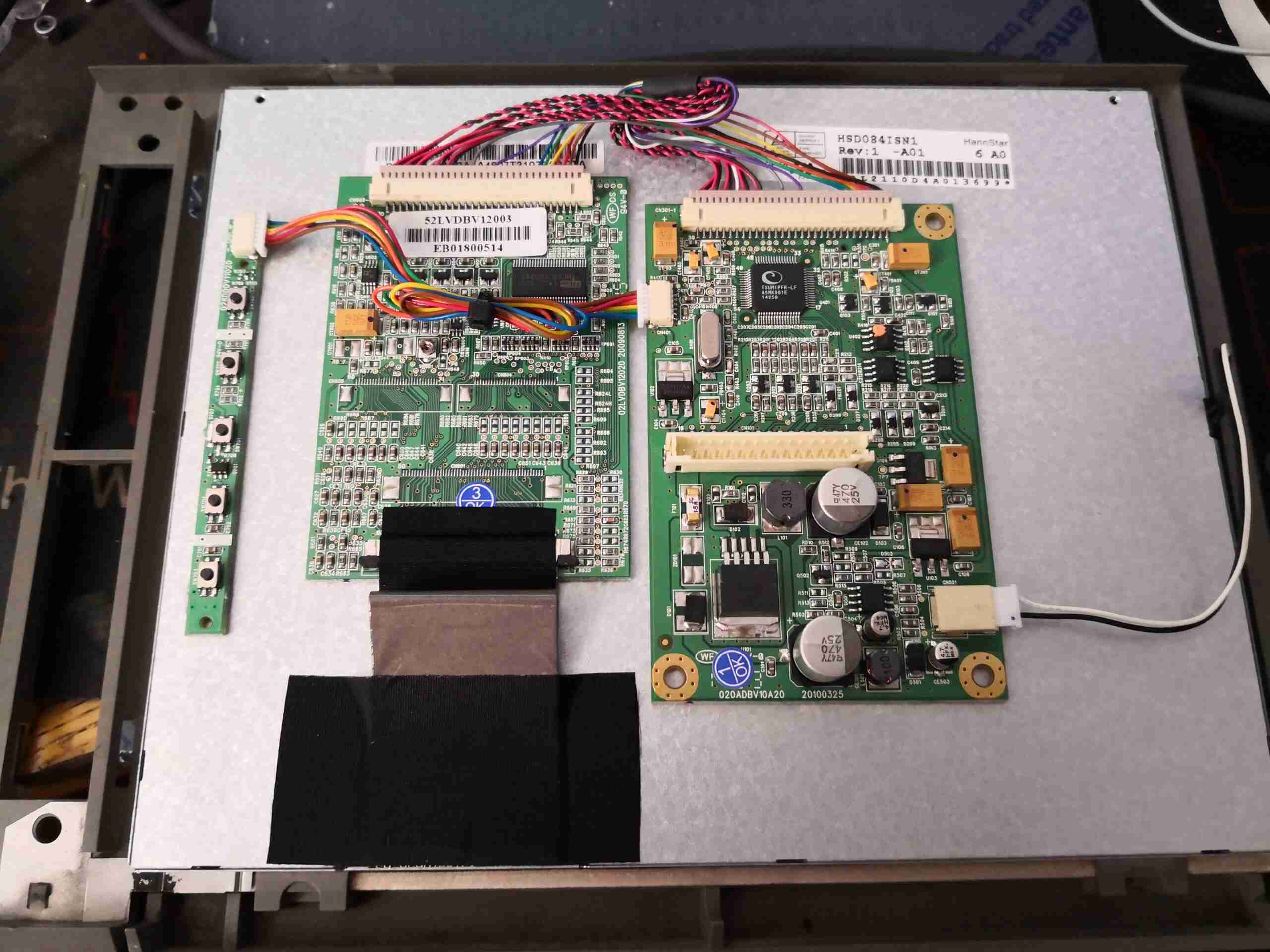
LCD Control PCBs
The donor 8.4″ LCD came from eBay in the form of a POS auxiliary display. I pulled the panel from the plastic casing, along with the control boards, and attached them all to the back. This LCD also had a sheet of toughened glass attached to the front, no doubt to protect against the Great Unwashed while in use! This was also removed.
Control Boards Mounted
A cut piece of plexiglas allows the boards to be mounted in the cavernous space the CRT once occupied, with some brass standoffs. 12v power & VGA are routed down to the LCD on the front of the analyser.
LCD Wiring
The LCD itself is tacked in place with cyanoacrylate glue to the securing clips for the glass front panel, which is more than enough to hold things in place. The input board which just has the VGA connector & power connector is glued edge-on to the metal back panel of the LCD, and is under little strain so this joint should survive OK.
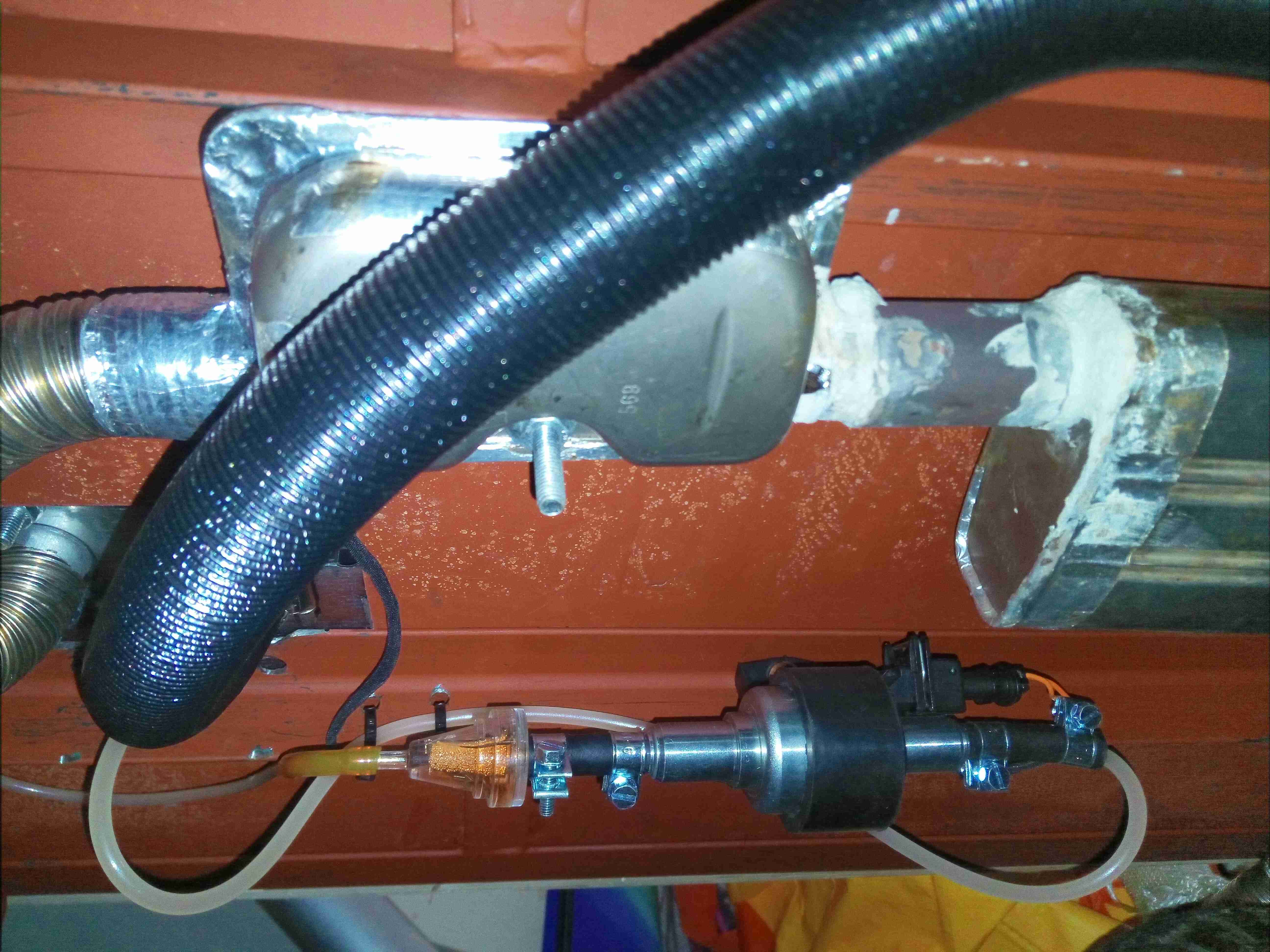
Since I fitted the new “8kW” diesel heater to the camping power trolley, it has occurred to me that there is a lot of energy in the exhaust gas stream that ordinarily would be wasted into the atmosphere. Since we’re all still on lockdown here in the UK, I figured it would be good to run an experiment to see if it was worth recovering this energy – in the form of heating water.
Heat Exchanger
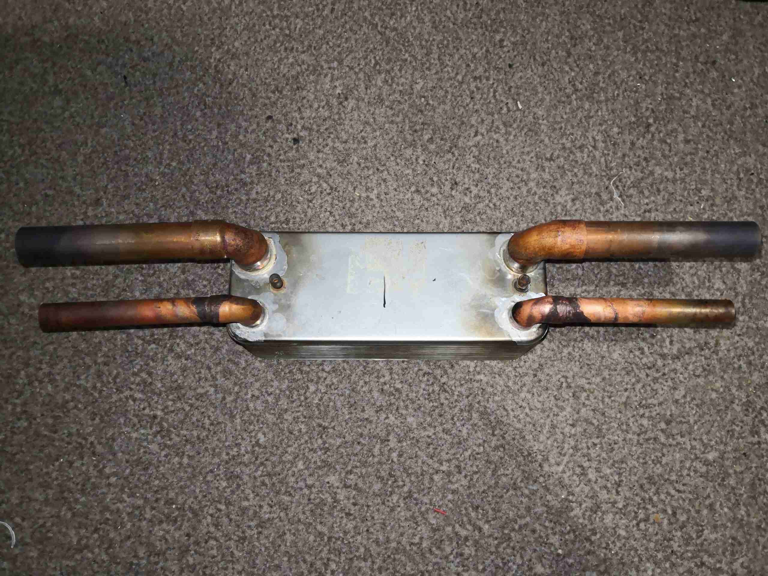
Some time ago, I stripped an old gas combi boiler, and recovered some parts – most important here the HDW plate heat exchanger. This large chunk of stainless steel is a stack of formed plates, brazed together, that usually would heat Domestic Hot Water. In this instance it’s being repurposed to transfer heat from exhaust gas to water.
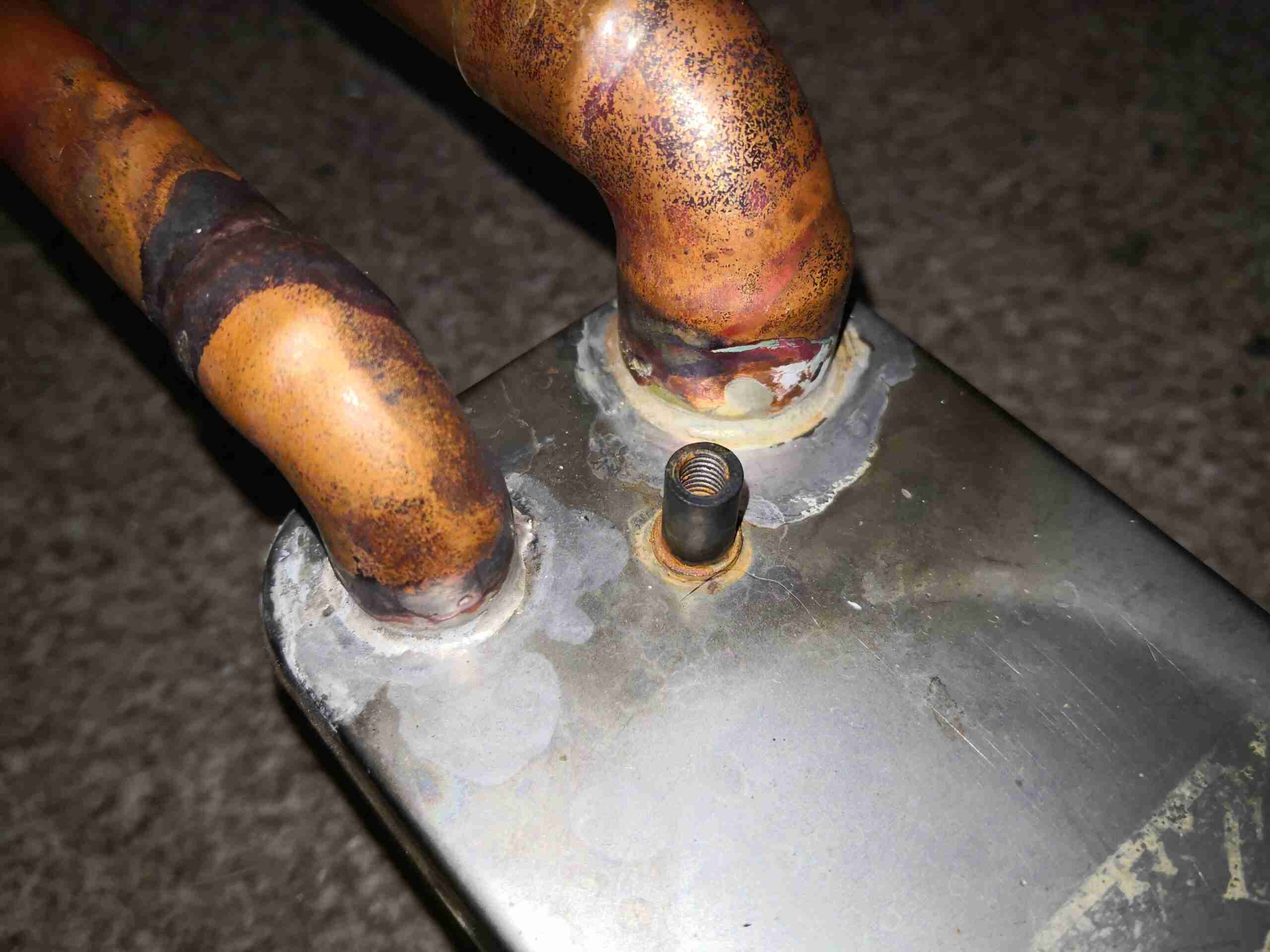
Brazed Connections
These heat exchangers are mounted in the boiler via a plate with O-Ring seals on, so they don’t really have fittings – just holes in the end plate. Solving this problem was simple – braze on some copper fittings with 55% silver brazing rod. The 22mm is the exhaust side, while the 15mm is the water side.
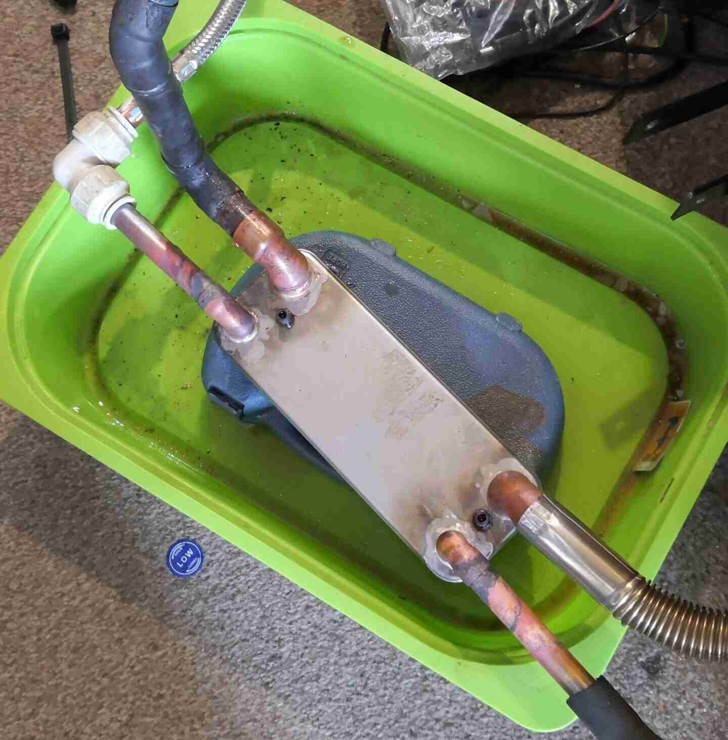
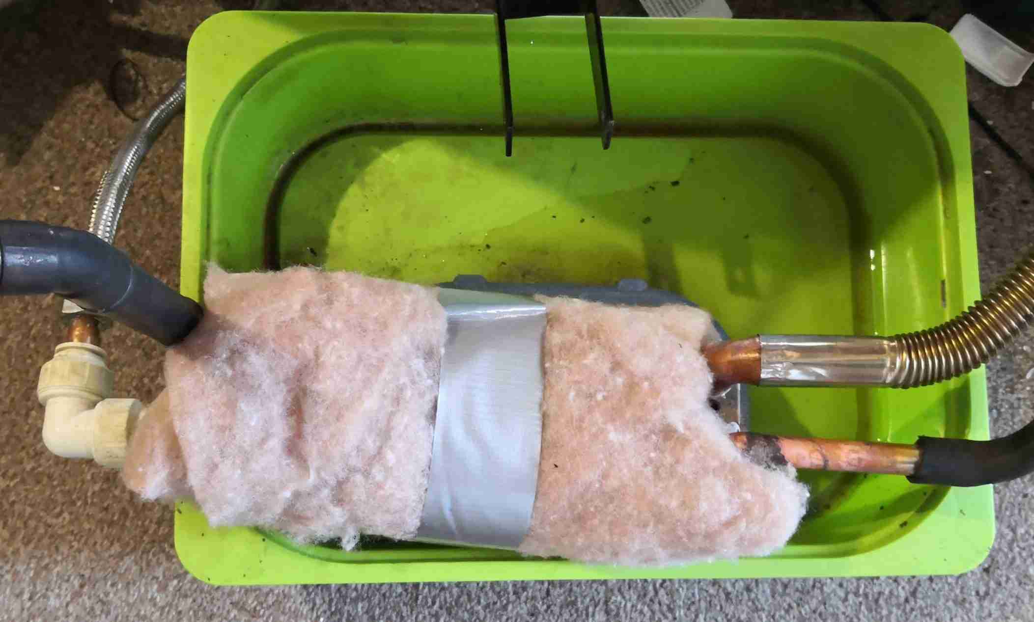
First Test
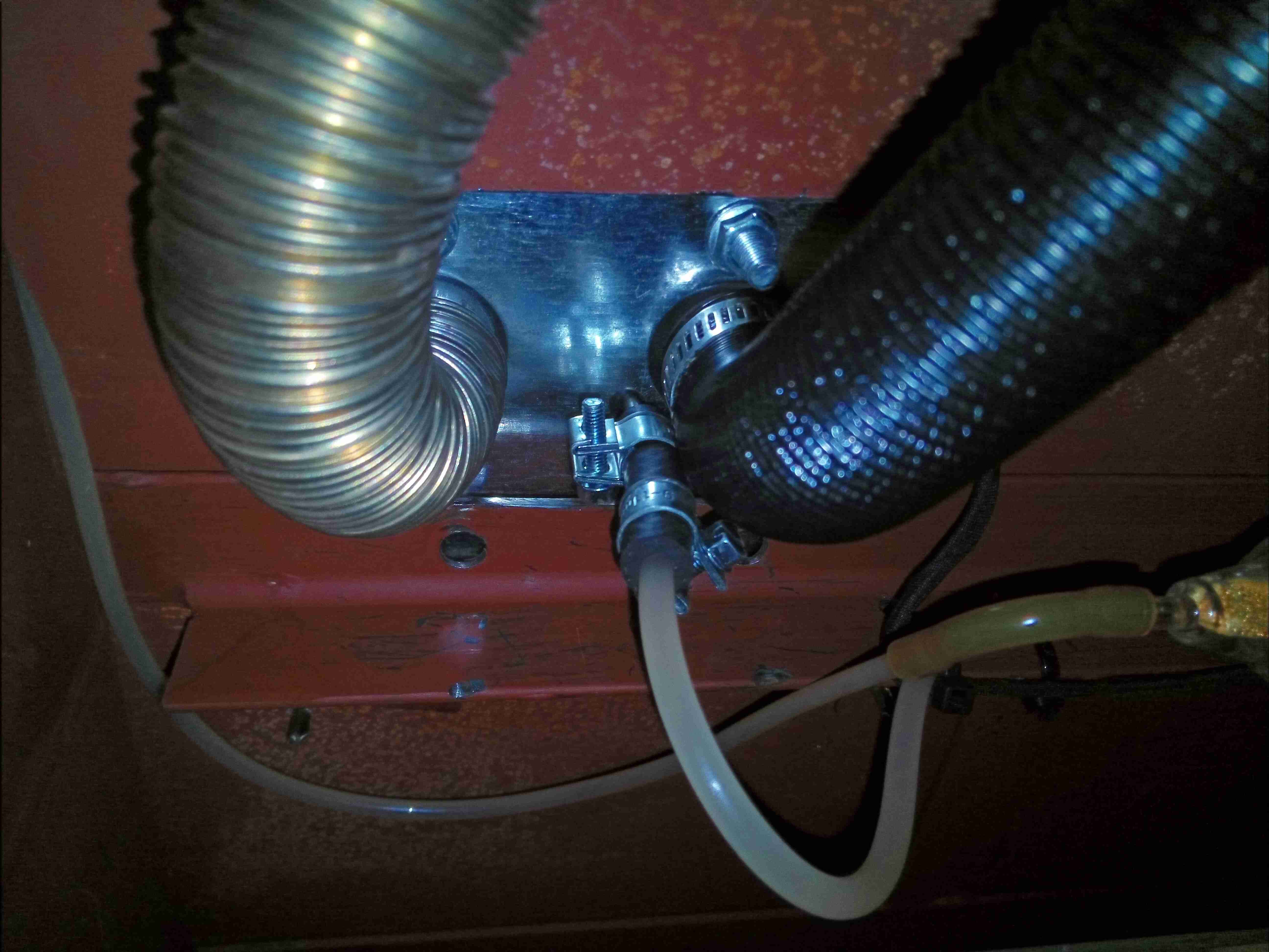
Cobbling together some random hose & fittings, along with a small water pump allowed me to run a first test. At this point there is no lagging at all on the exhaust system from the heater, so it’s going to shed a lot of exhaust heat into the air before it even gets to the heat exchanger. However I was able to get around 600W of heat into 15L of water, heating it up nicely. The heat exchanger is plumbed contra-flow here – exhaust comes in via the stainless tube on the bottom right, and water comes in through the speedfit elbow on the top left.
Lagged Heat Exchanger
After the temperature of the water tank hit a plateau at around 45°C, I decided to insulate everything the best I could with what I currently have. I’ve wrapped the heat exchanger with some recycled PET insulation here, just to hold the heat inside. I’m not concerned about the exhaust outlet being in contact with the fluff – this system is so effective at pulling the heat out of the exhaust that the gas exiting the far end is totally cold!
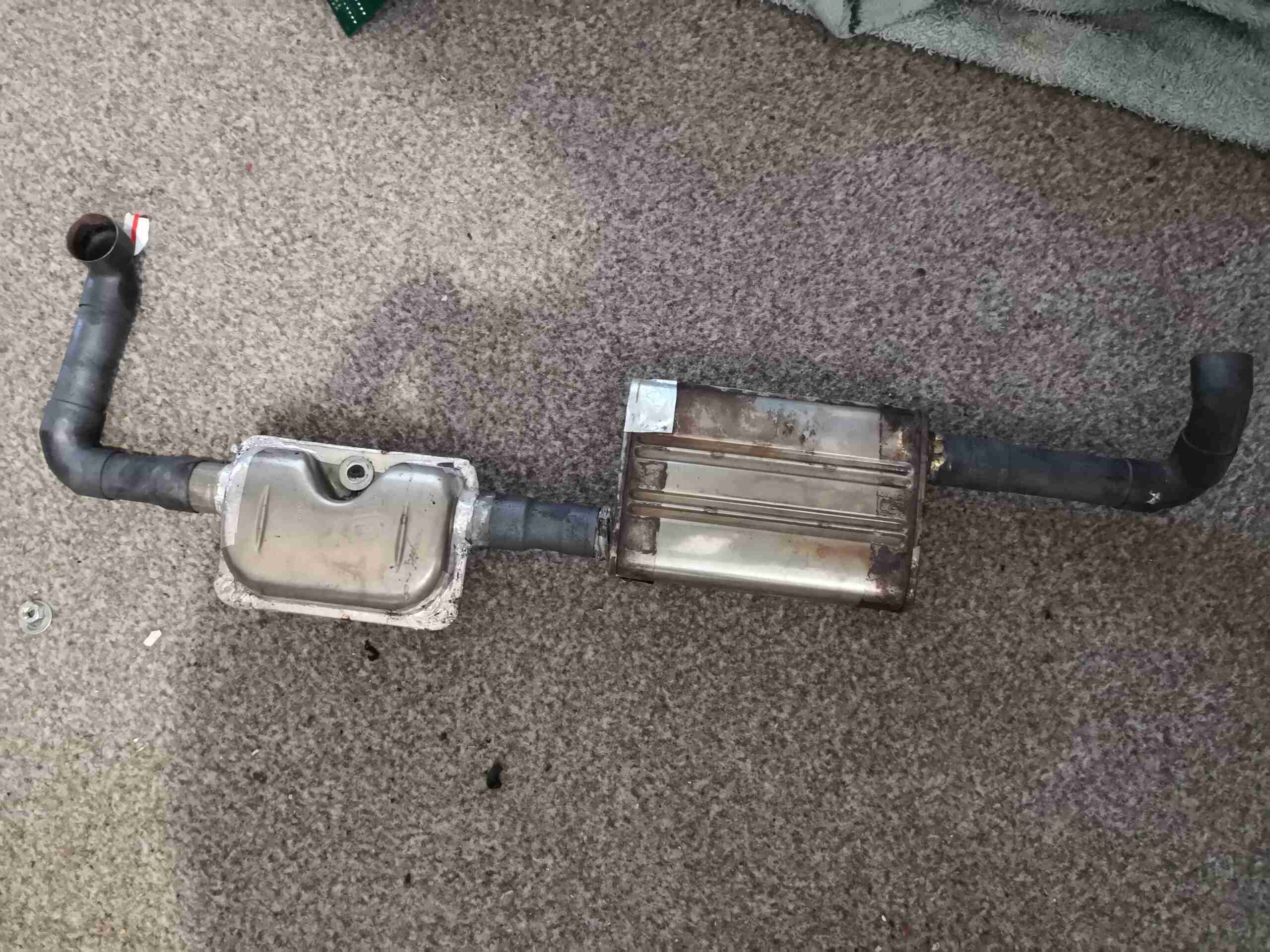
Unlagged Exhaust
Now it was time to get the exhaust system under the trolley insulated. This is the system removed from the unit entirely. This is constructed from copper pipe, brazed onto standard silencers. Deadening the sound from the unit is important, as this gets used on campsites!
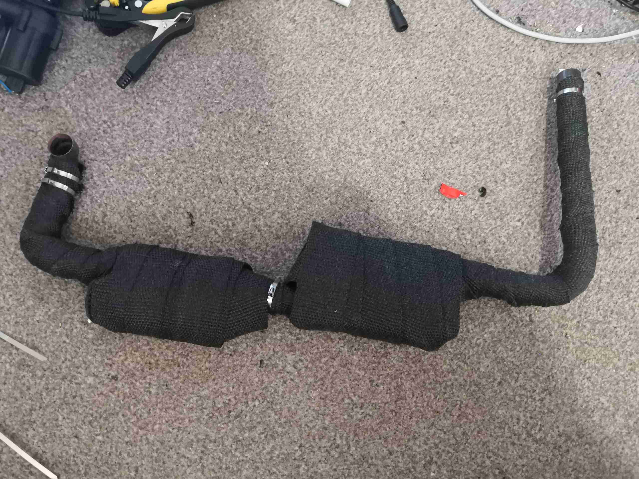
Fibreglass Tape Insulation
An hour & some itchiness later, the exhaust is completely covered in fibreglass insulation, secured in place with stainless steel ties.
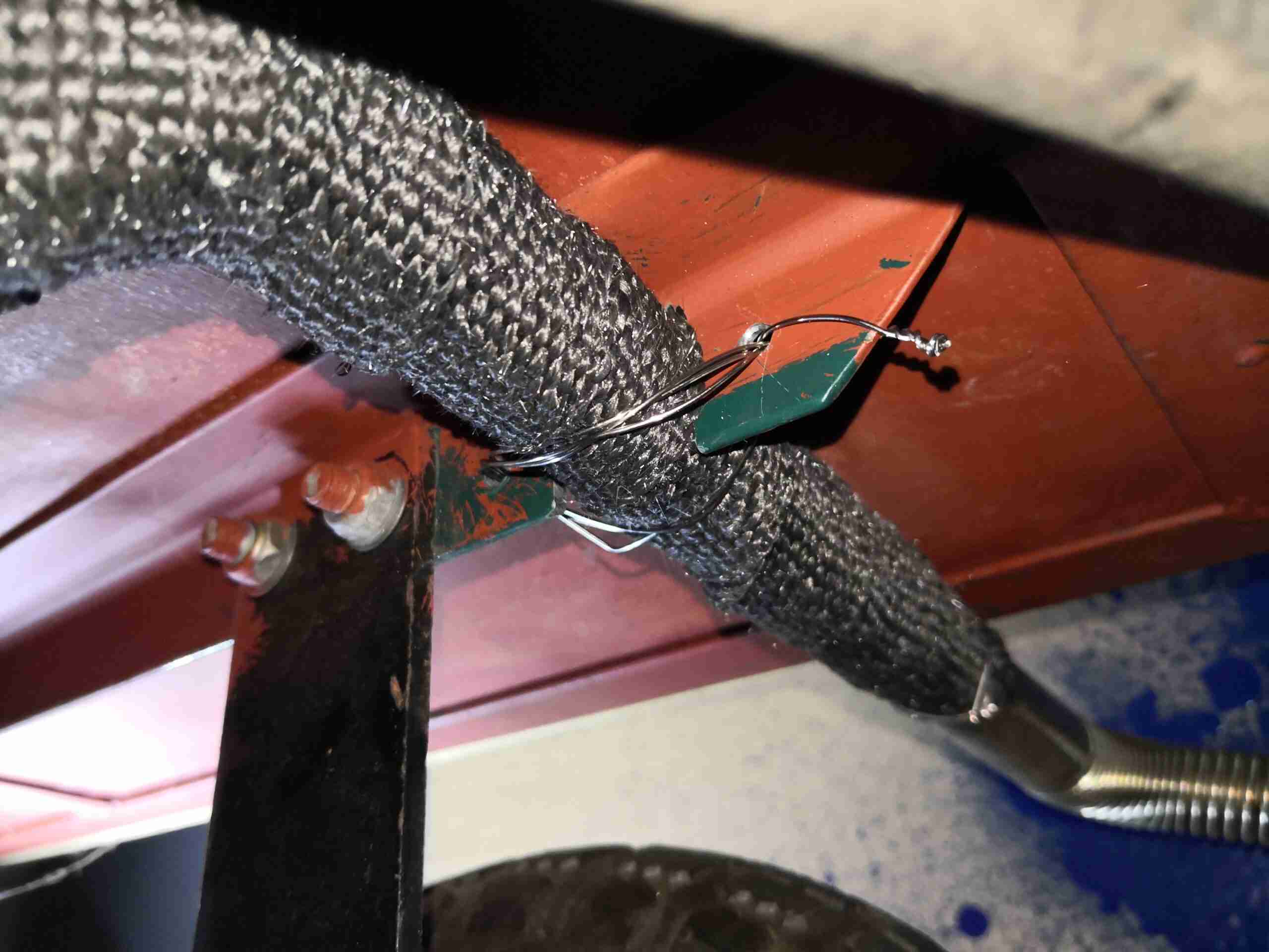
Exhaust Hanger
The exhaust originally passed through a close-fitting hole in the frame rail which would obviously not work now due to the thickness of the insulation layer, so this was modified with a grinder. Since there was now no support for this end of the exhaust, a pair of drilled holes & some stainless steel wire form a nice hanger!
With all this insulation in place (including around the tank & pump), the rig is now able to easily hit 65°C within a short time, so there has definitely been an improvement. At this point, it’s clear that waste heat recovery is worthwhile, so I’ll be building a proper rig to capture this energy for reuse!
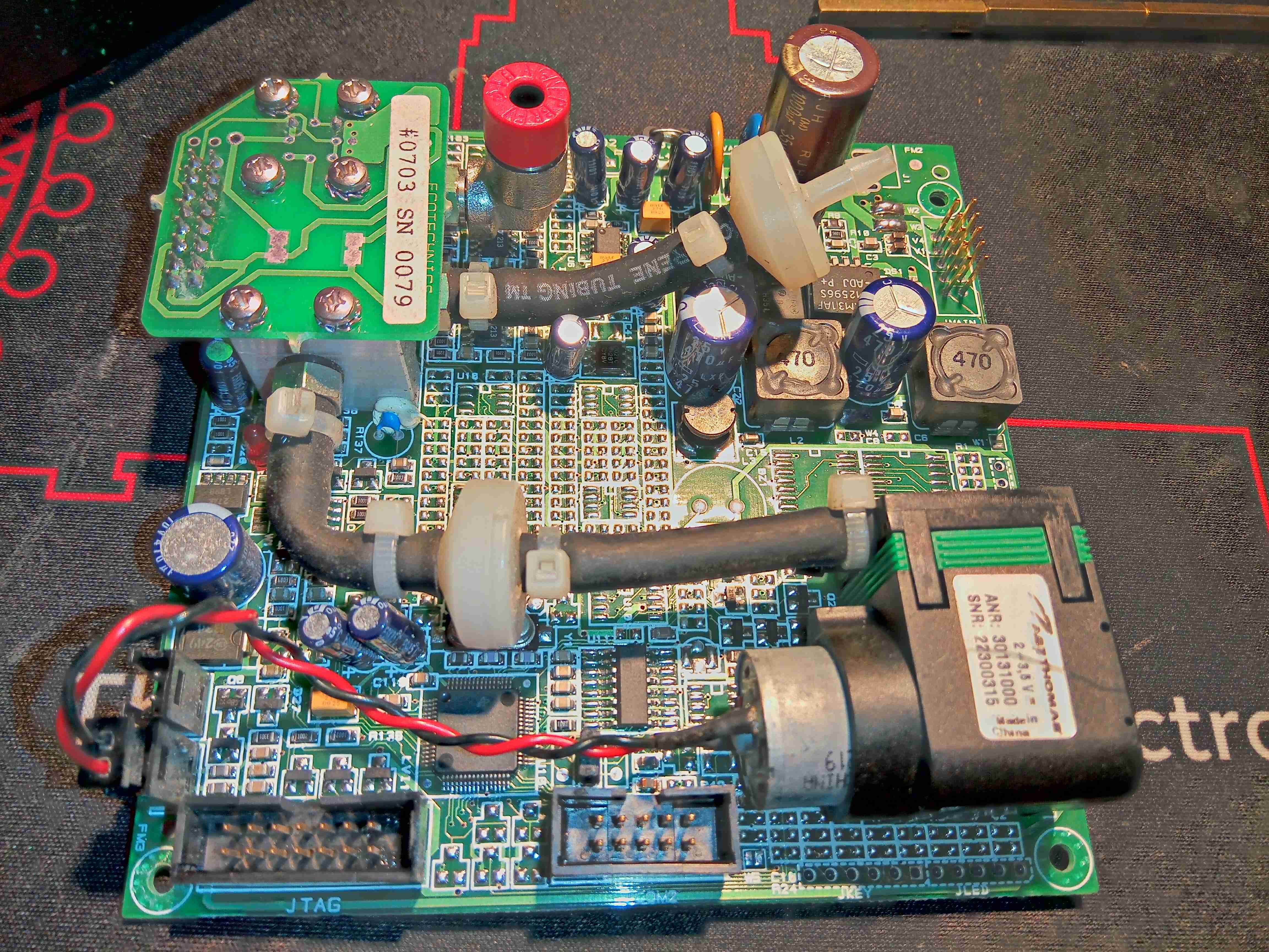
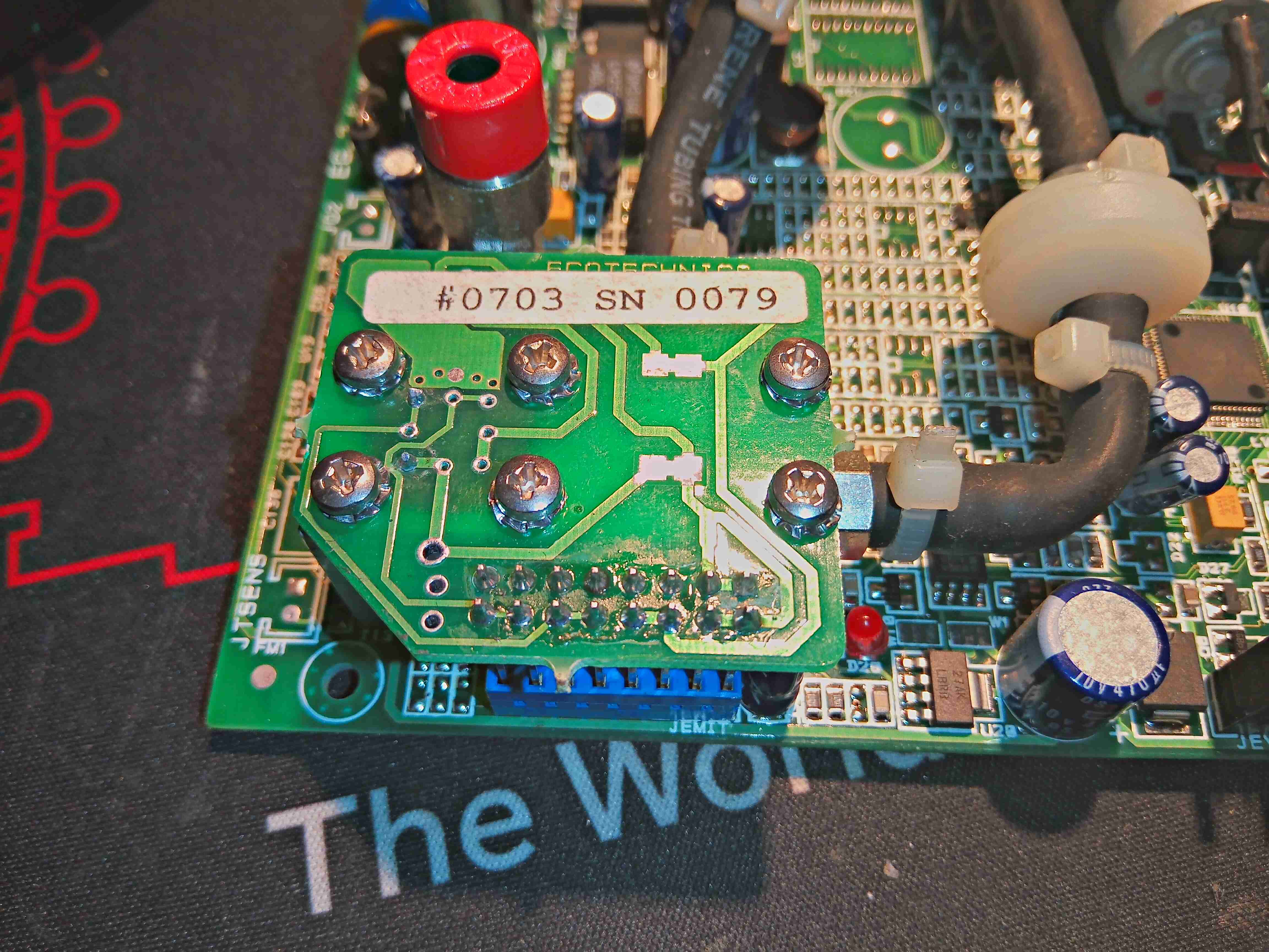
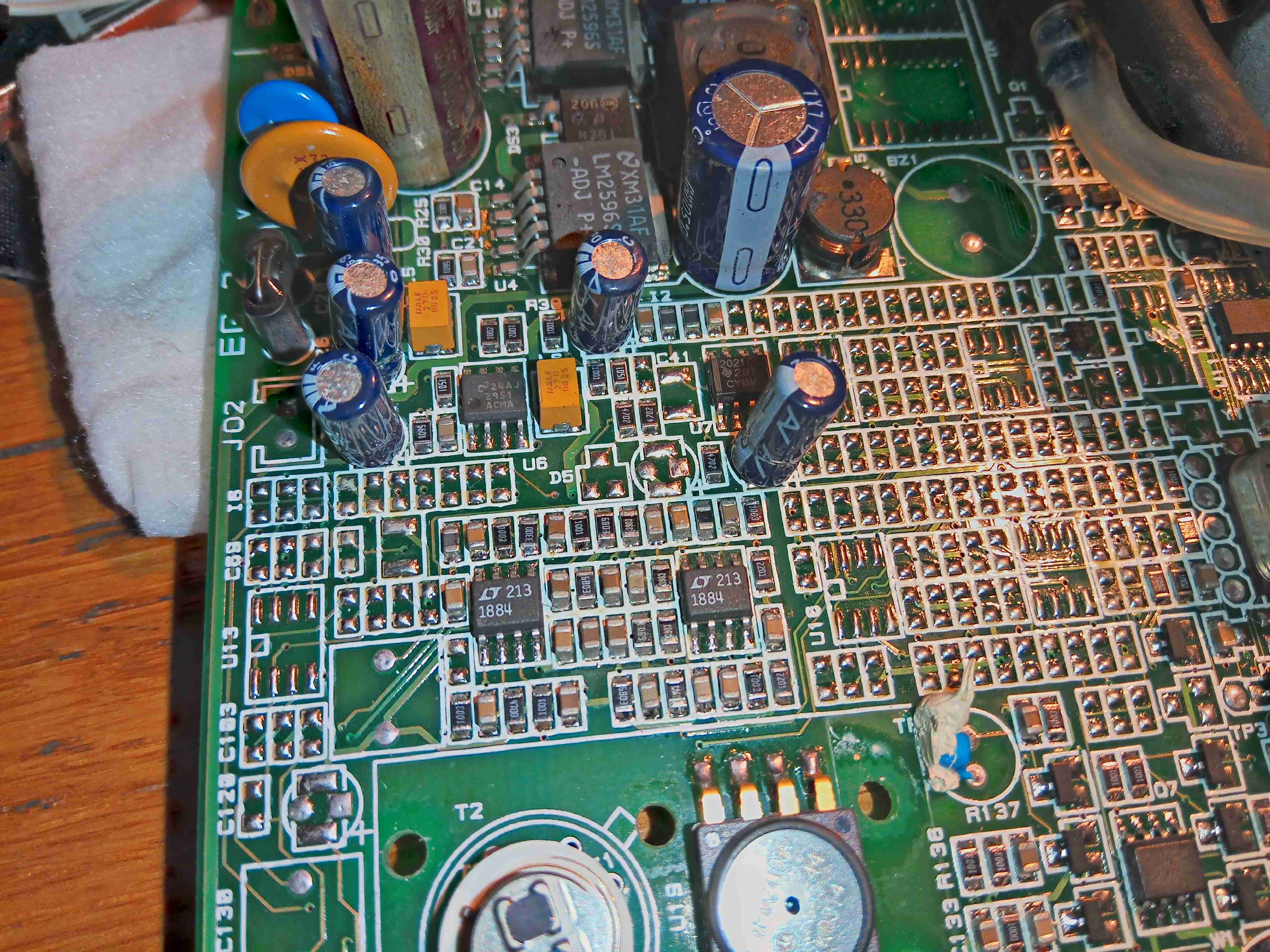
This unit recently appeared on eBay, as a spare part from a refrigerant charging machine, and I figured it would make a good explorational post. This unit analyses the purity of R-134a refrigerant gas, using an Infrared sensor cell, and communicates over RS-232.
The sensor cell itself is at the top right of the board, we’ll get to that later on. There’s a small diaphragm pump at the lower right, for purging the cell with air. The port with the red cap is the outlet, and the remaining open hose barb is the input of gas to be tested. This would connect to a flow regulator & solenoid valve that the board controls.
It’s pretty clear that this board has multiple applications from all the unpopulated components. There’s space for a keypad, indicator LEDs & an LCD on board, so maybe this can also be fitted to a handheld analyser?
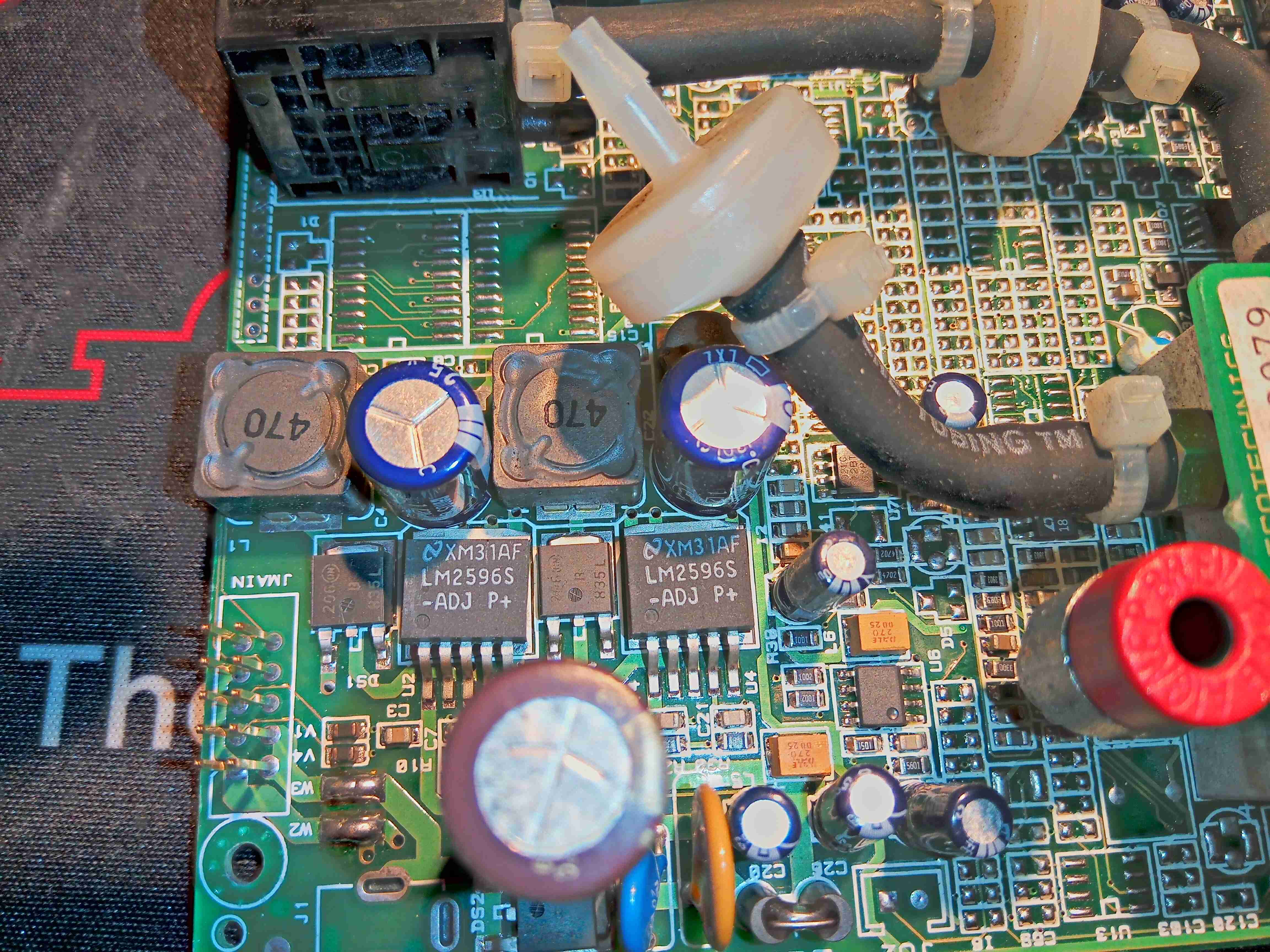
Power Supply
From looking at the input circuitry, I can surmise that the input voltage is somewhere between 12-24v DC, as there is a 35v input electrolytic filter capacitor. There’s a couple of switching regulators which generate 5v & 3.3v rails for the board, with some input fusing.
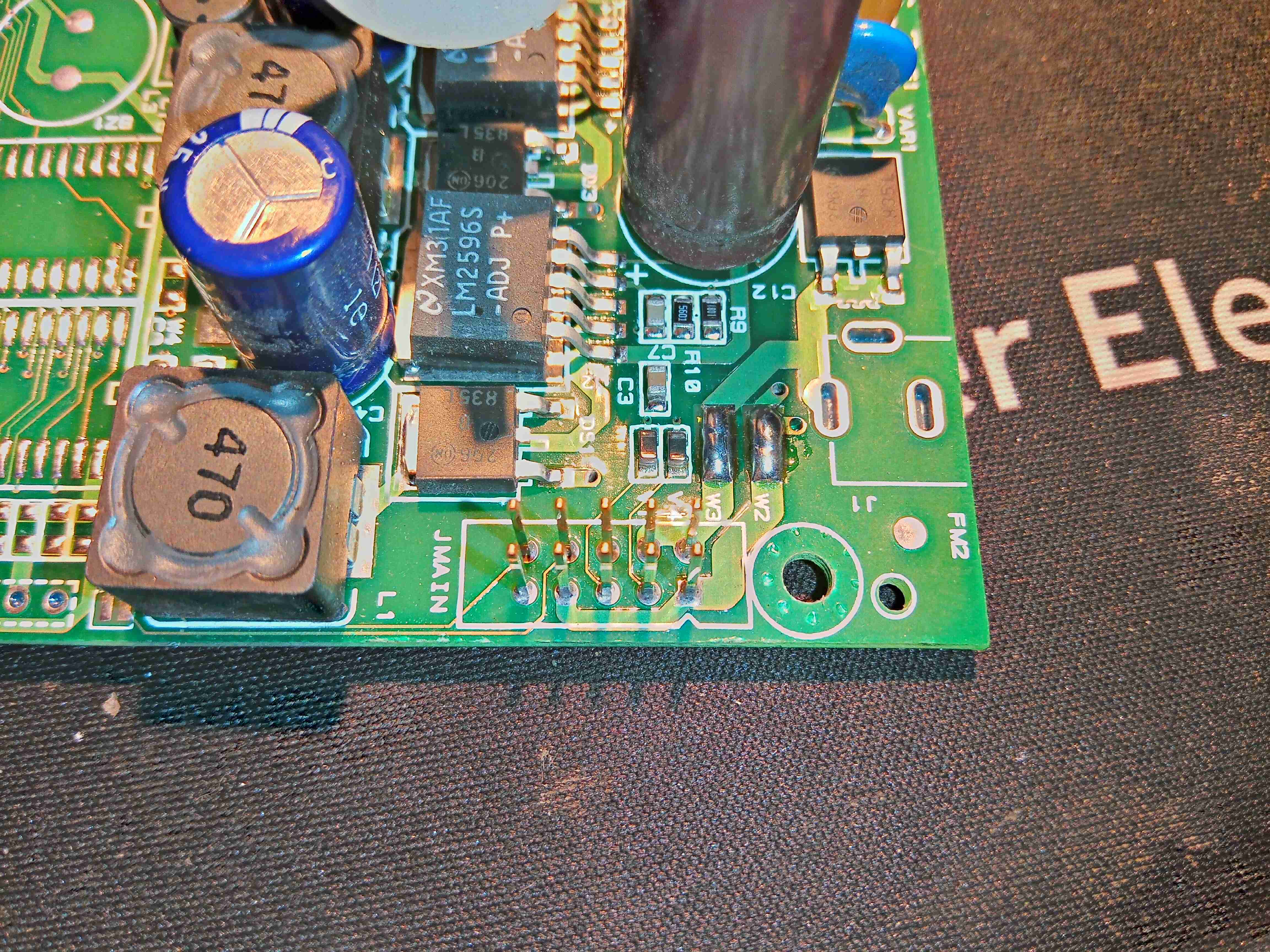
Main Connector
There’s two serial links on this board, driven from the main microcontroller – the primary one is on the connector marked JMAIN, along with the power input & a couple of other unknown signals.
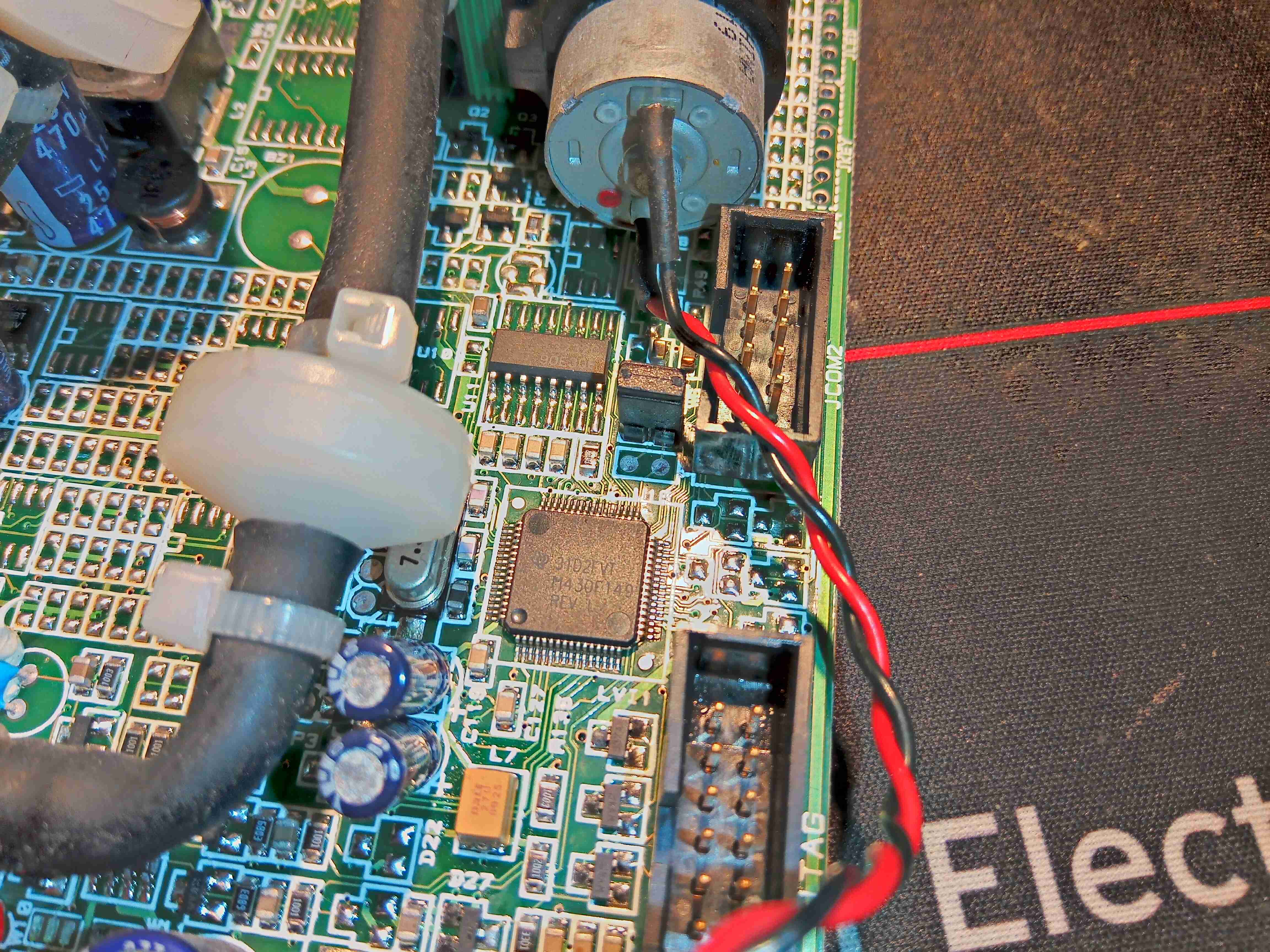
MSP430 Microcontroller
Over on the other side of the board is the brains of the operation – an MSP430 microcontroller, with an RS232 transceiver IC & another RS-232 port marked COM2. The remaining connector is a JTAG port for the micro.
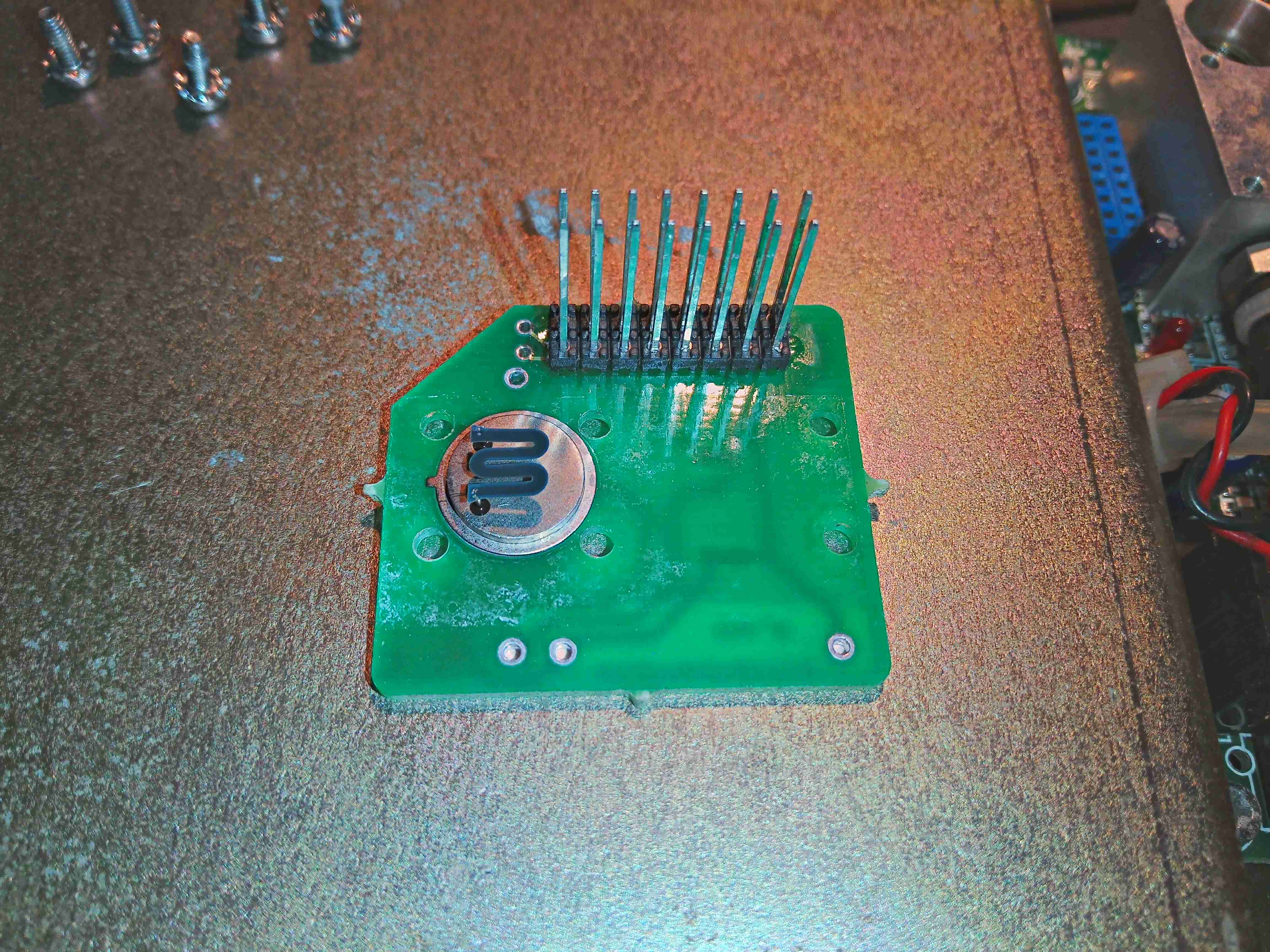
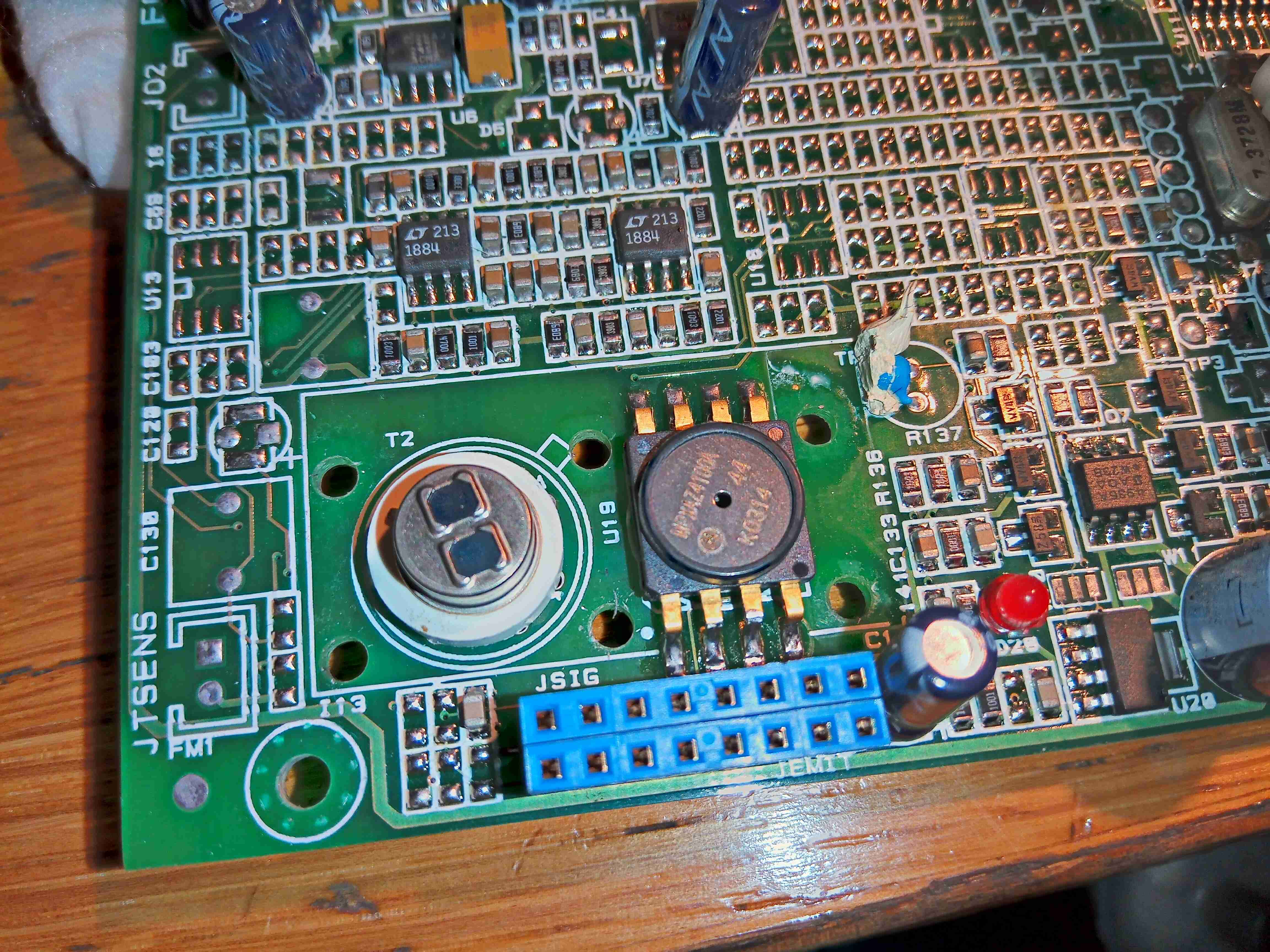
Gas Analysis Cell
Here’s the gas analyser cell itself, sandwiched under another board. There’s a temperature sensor on the side of the cell at the bottom, and even though there’s many pins on the header here, only a couple are actually used for the IR emitter.
IR Emitter
Removing the screws from the top allows the board to be removed, which exposes the Mid-IR emitter component with an exposed element. This looks to be very fragile, so I won’t be messing with this much. From metering the connections, this appears to be driven at about 2v from the microcontroller.
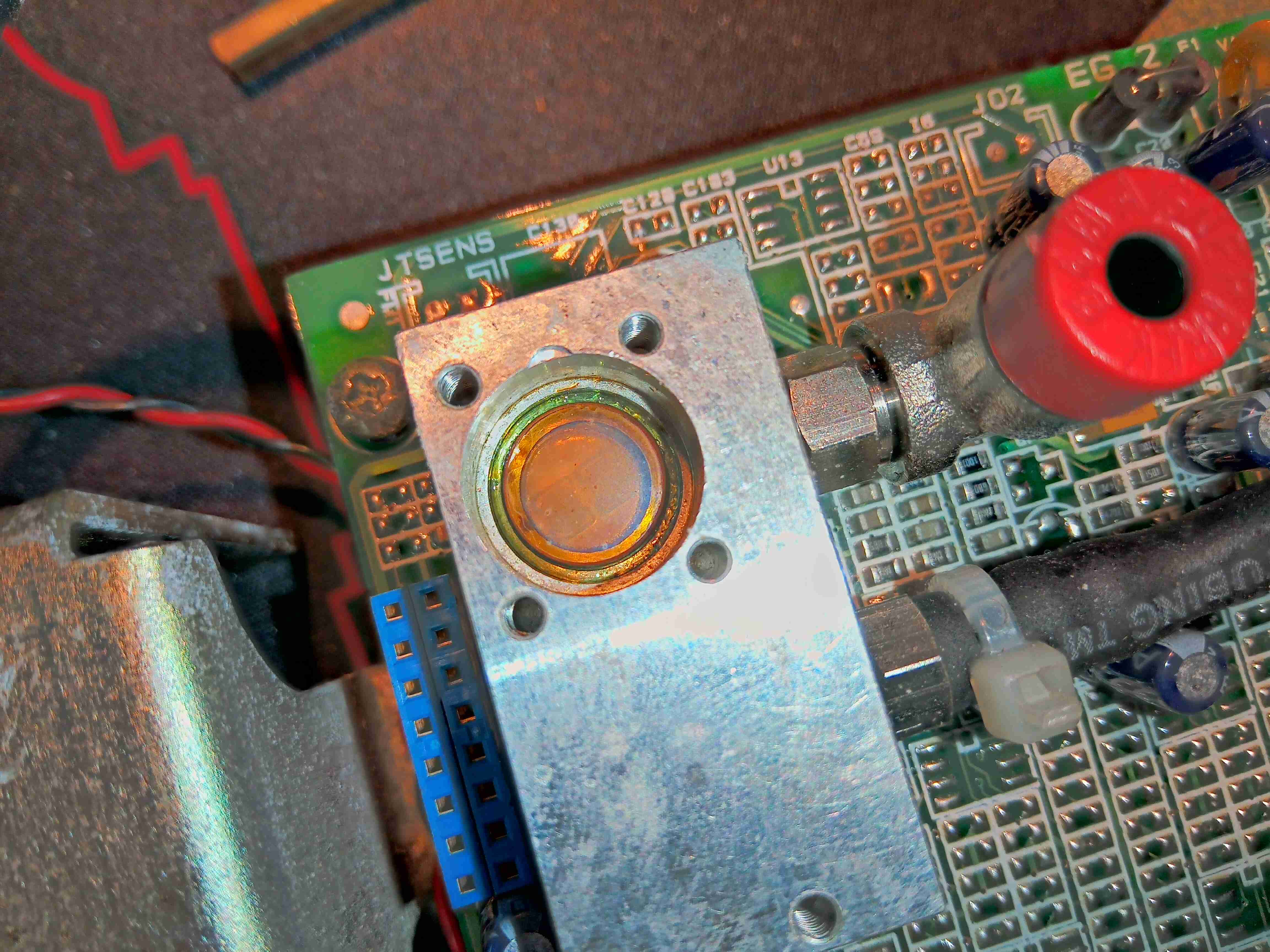
Top Of Gas Cell
The window into the gas cell looks to be made of something exotic – considering the IR application & the colour, this is probably Zinc Selenide.
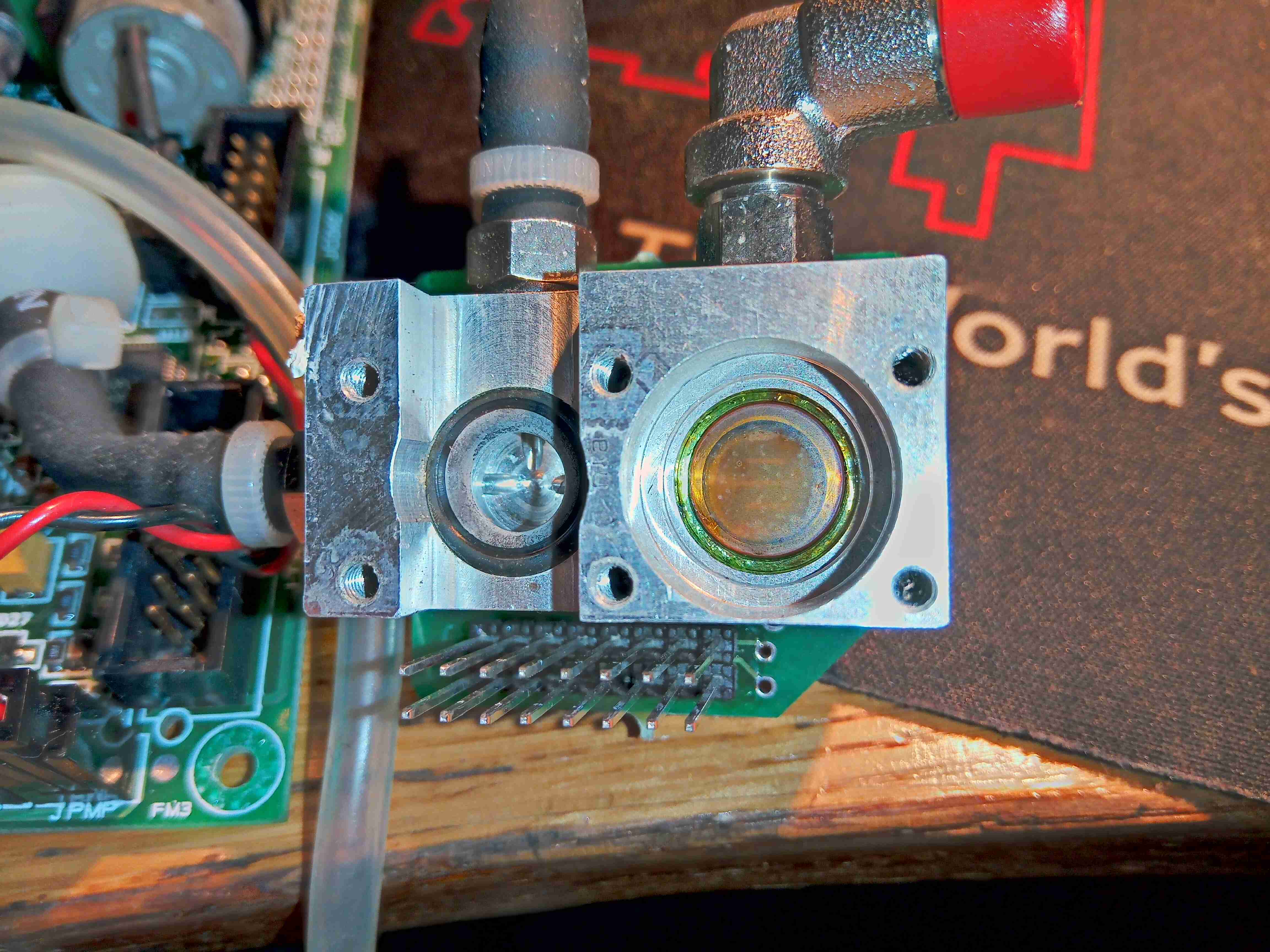
Gas Test Cell
Removing some more screws on the bottom exposes the bottom of the cell with another IR window, and an O-Ring where a pressure sensor sits.
Output Amplifiers
There’s a couple of very accurate LT1884 Rail-To-Rail Precision Op-Amps next to the cell, most likely used to measure the output from the sensor itself.
Mid-IR Sensor & Pressure Sensor
Finally, there is a dual-window thermopile sensor, and a pressure sensor. I wasn’t able to get any information on either of these, but I did find some ranges of sensors for Mid-IR measurement operations, that mentions a wavelength around 10µm for R-134a spectroscopy.
I will try to get this module going & measuring some gases, if I can work out how to talk to it – I already know the serial lines so it’s just working out a command set. If anyone has any information on these, please do get in touch! A service manual for the refrigerant machine this came out of would be good!
So, it’s time to finish off the upgrades to the core storage server on my network. Now a new motherboard, CPU & RAM have been obtained (MSI GA-X58-USB3), Core i7 950, 12GB), along with new SAS/SATA HBAs for the disk rack I can get everything fitted into place.
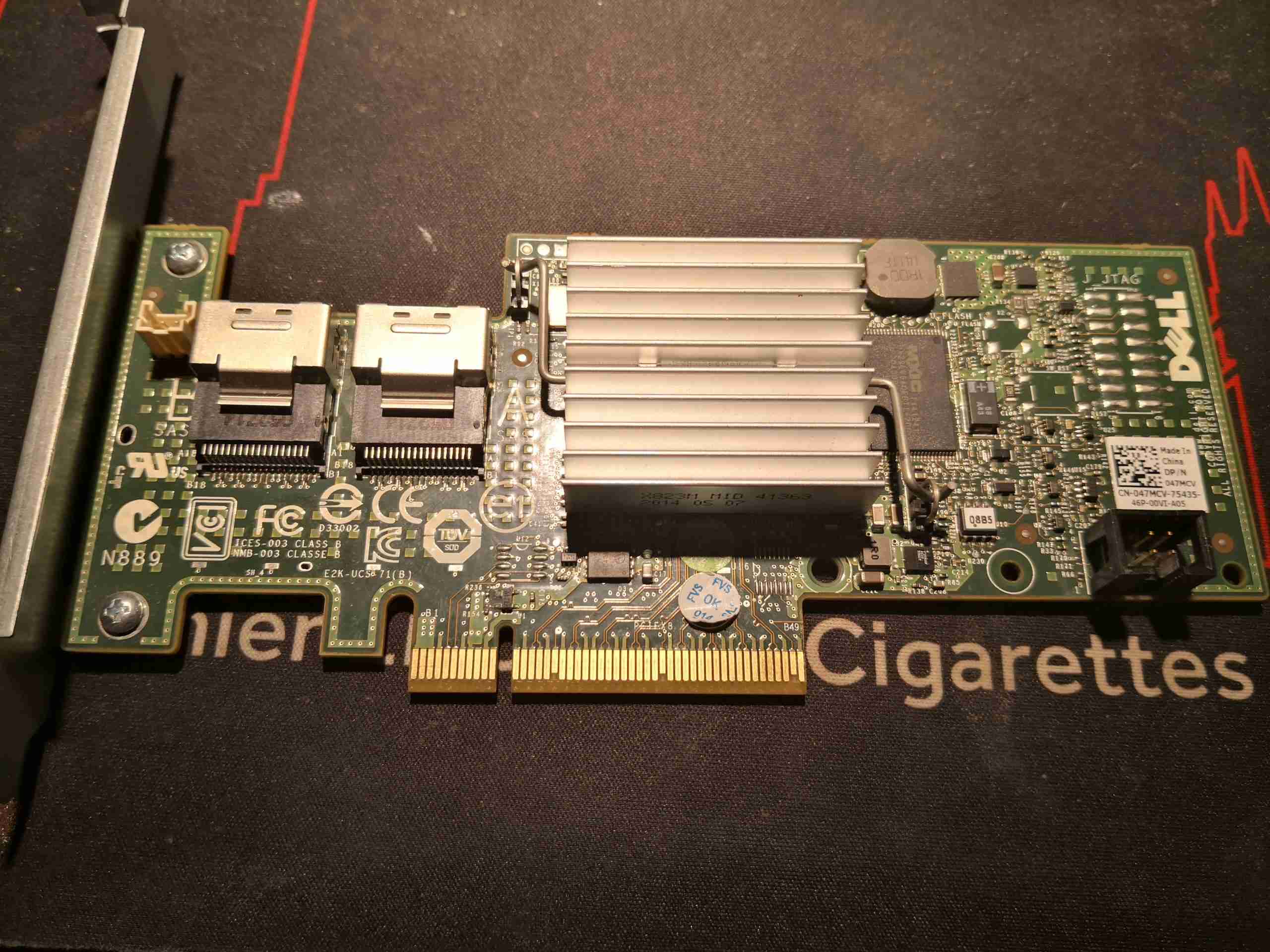
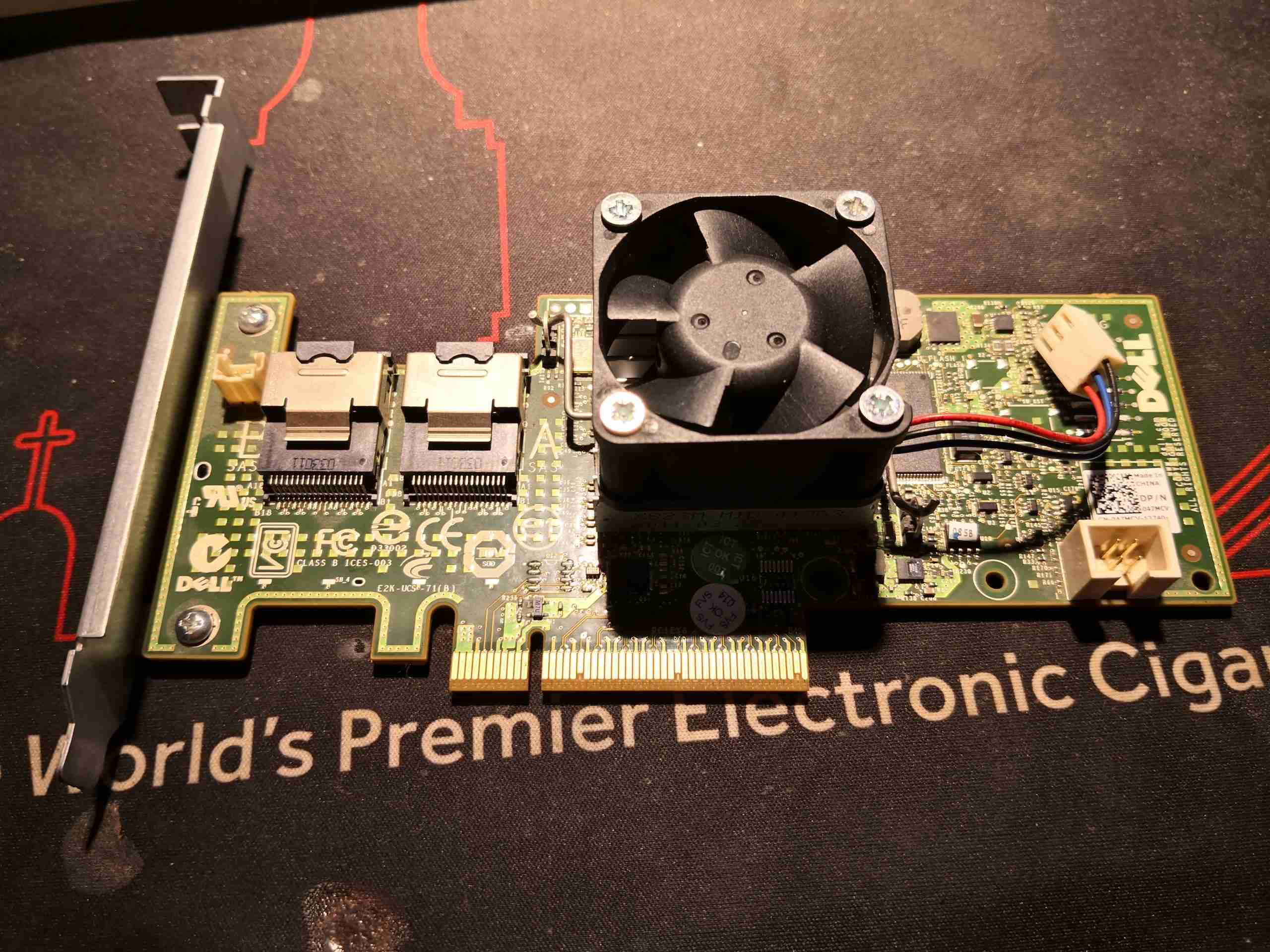
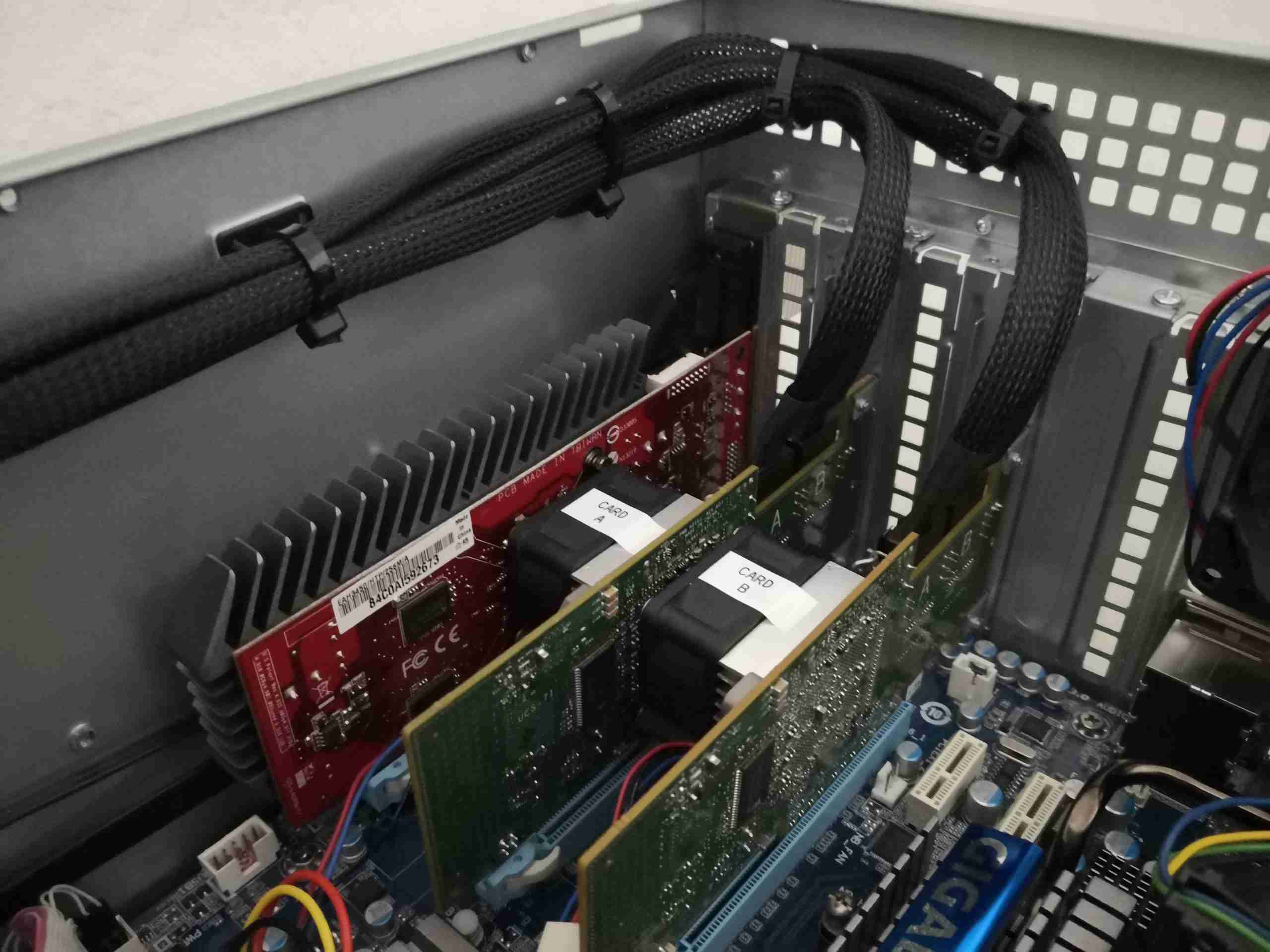
Dell H200 SAS RAID Card
Proper branded LSI HBA cards are expensive so I went with the cheaper option & obtained a pair of Dell H200 RAID cards. These have custom firmware flashed to them, but luckily can be crossflashed to a standard LSI firmware to become an LSI9211-8i card – providing 8 lanes of either SAS or SATA connectivity on a pair of SFF-8087 ports. Flashing these cards was very simple, once I managed to work my way into the EFI shell on my main machine, which I was using to do the flashing. Find all the firmware files & required software here:
One thing I left out from the flashing was a BIOS – this means that the boot process is speeded up, but also means the system BIOS cannot see the disks connected to the cards, so they’re not bootable. This isn’t a problem however, as I never plan on booting from the data storage disk array.
Active Cooling
The SAS2008 RoC (RAID on Chip) on these cards runs at around 8.5W thermal power, so some active cooling is required to keep temperatures within check. I have attached a 40mm fan to each card’s factory heatsink, using M3x25mm screws. Getting the screws to grab the heatsink was the tricky bit – I needed to crimp the outer corners of the fins together slightly, so when the screws are driven in, the gap is forced to expand, which grabs the threads. The fans will be connected to spare headers on the motherboard for speed monitoring.
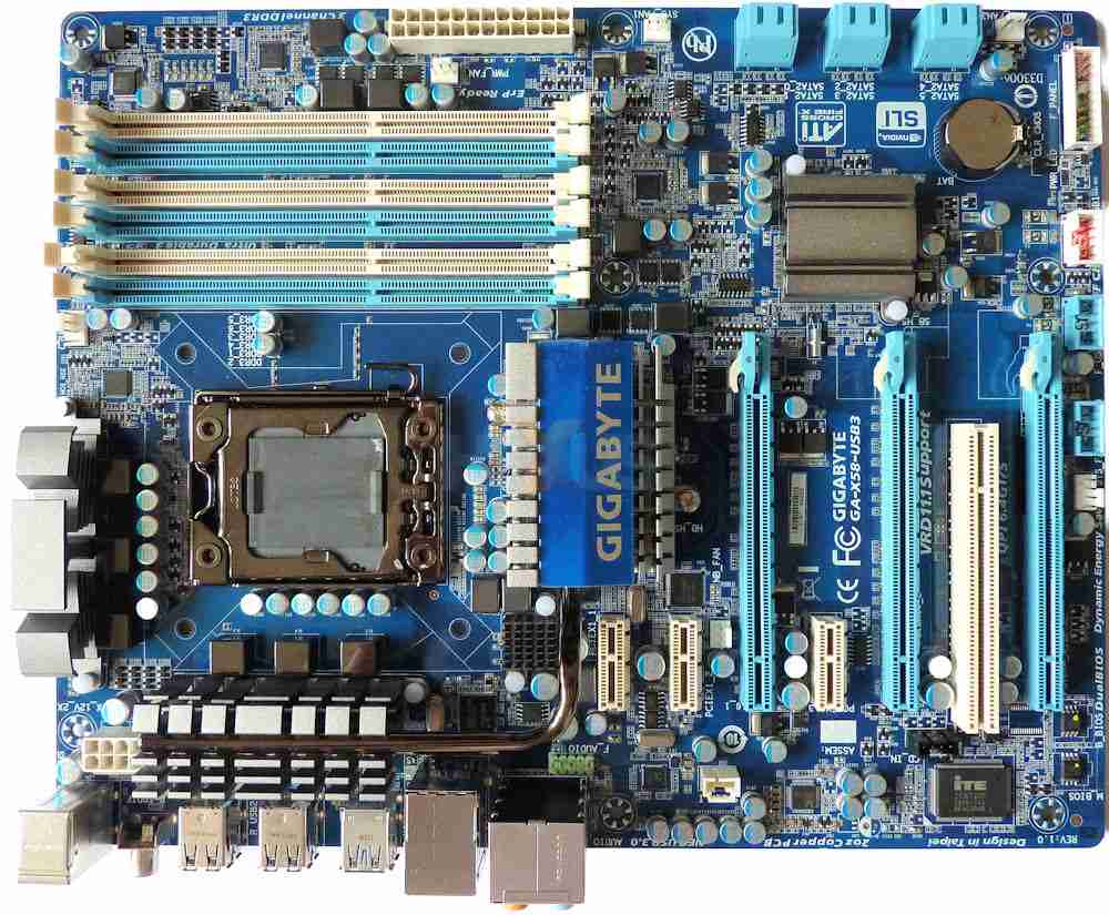
GA-X58-USB3
It was a struggle finding a motherboard with the required number of high-lane-count PCIe slots. Even on modern motherboards, there aren’t many about within a reasonable price range that have more than a single x16 slot, and since I’m going with the new HBAs, a single slot is no longer enough. The motherboard I managed to obtain has a pair of x16 slots, and a x4 slot (x16 physical), along with a 3 x1 slots. The only downside is there’s no onboard graphics on this motherboard, so an external card will be required. Another cheapie from eBay sorted this issue out.
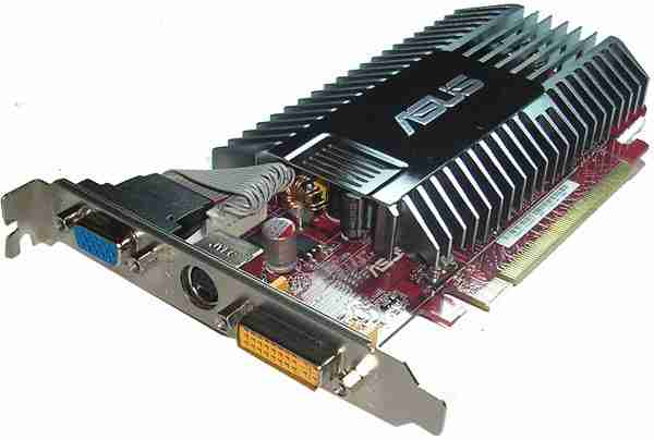
ATI Radeon HD3450
Since I need to use the x16 ports for the disk controllers, this card will have to go into the x4 slot.
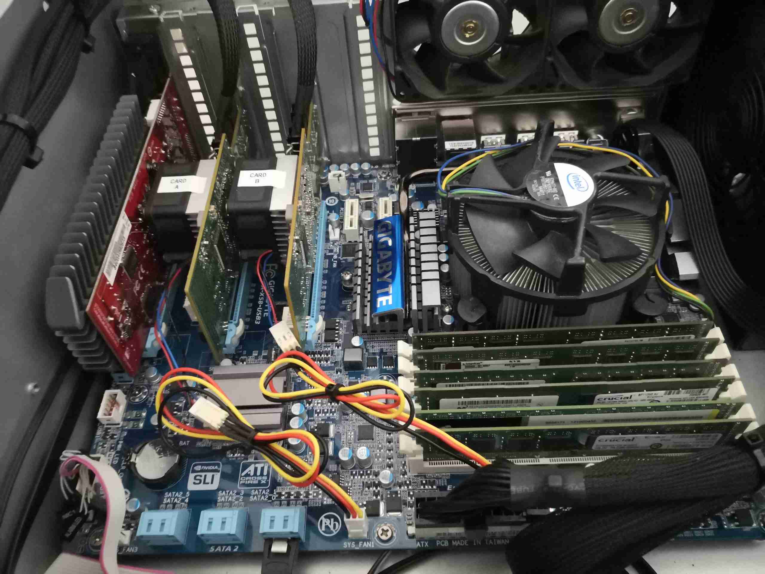
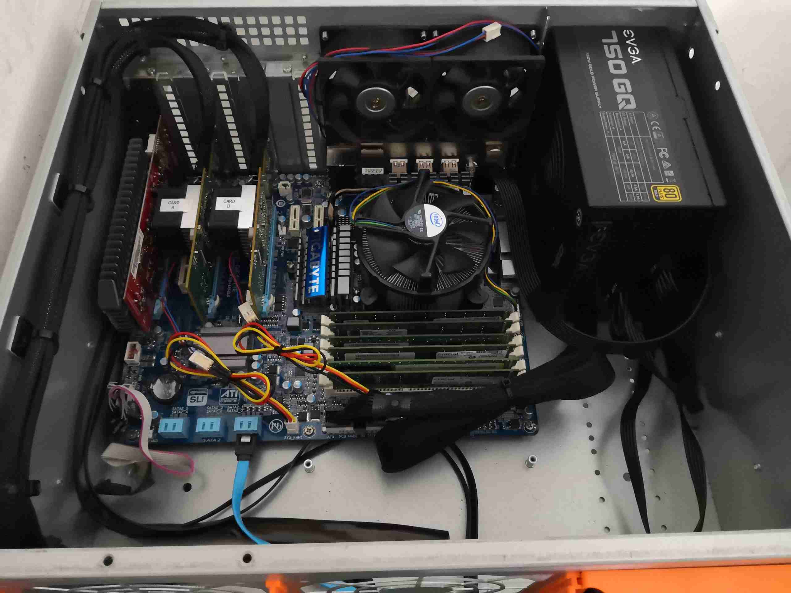
Motherboard Installed
Here the board has been installed into the new chassis, along with it’s IO shield. Both HBA cards are jacked into the x16 slots, with the SAS/SATA loom cables attached. I did have to grab longer cables – the originals I had were only 500mm, definitely not long enough to reach the ports on these cards, so 1m cables are used. The fans are plugged in with extensions to a pair of the headers on the motherboard, but the MB doesn’t seem to want to read RPM from those fans. Nevermind. While the fans are a little close to the adjacent cards, the heatsinks run just about warm to the touch, so there’s definitely enough airflow – not forgetting the trio of 120mm fans in the bulkhead just out of shot, creating a breeze right through the chassis.
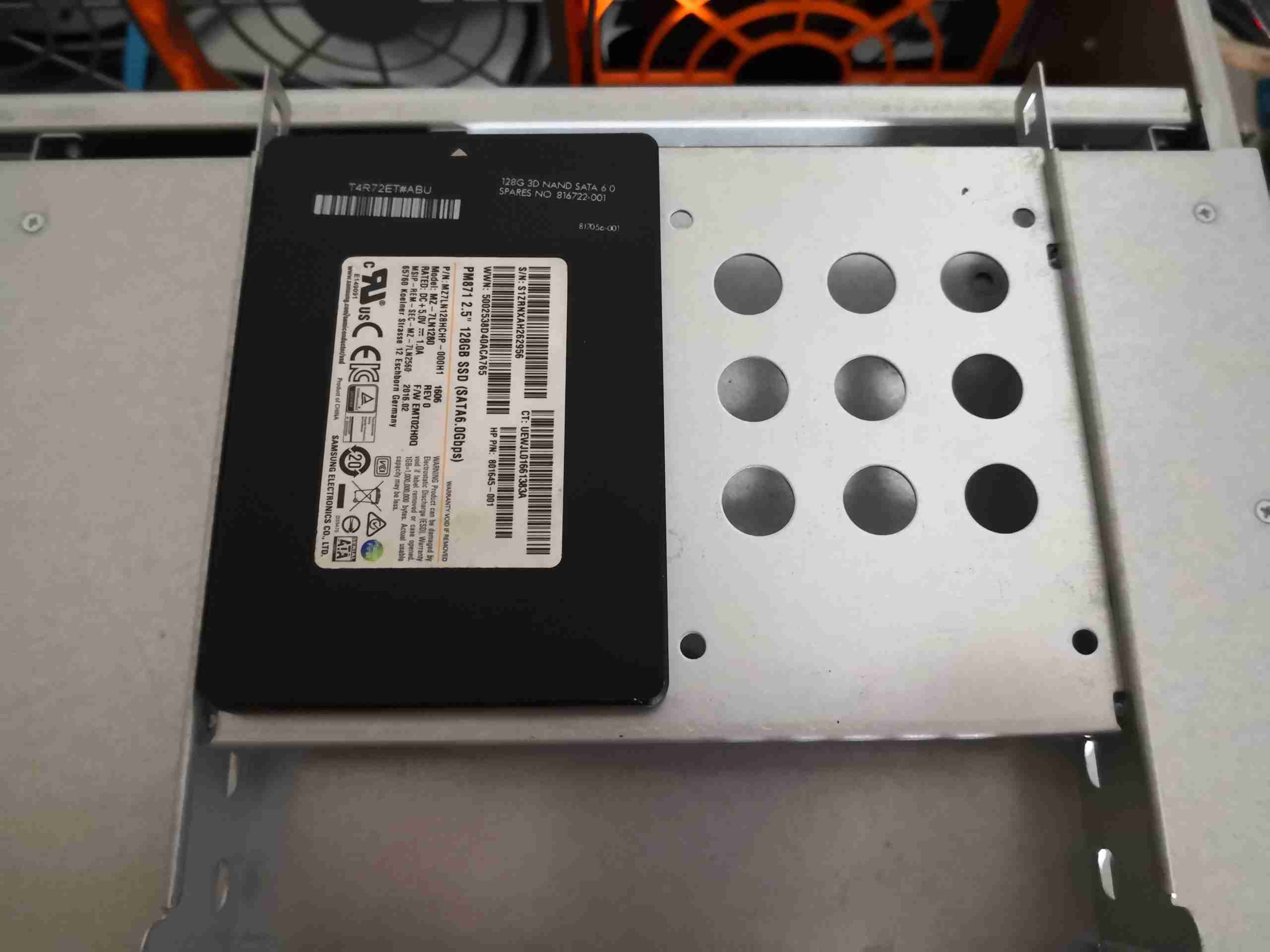
Boot SSD
Since the onboard SATA ports are in a better position, I was able to attach the boot SSD to the caddy properly, which helps tidy things up a bit. These slot into the 5-¾” bays on the front of the chassis, above the disk cage.
Loom Closeup
To take up the excess cable length, and tidy things up, the data loom to the disk cage is cable-tied to self-adhesive saddles on the side of the chassis. This arrangement also helps cooling air flow.
Server Overview
With the new components, and the cabling tied up, things inside the chassis look much cleaner. I’ve rationalised the power cabling to the disk backplanes down to a a pair of SATA power looms.
So I figured it was time to get a hardware update sorted for my network’s core storage server, which I have posted about before. The way I had the drives anchored to steel rails really doesn’t make moving or replacing disks easy, so a proper case needed to be sourced.
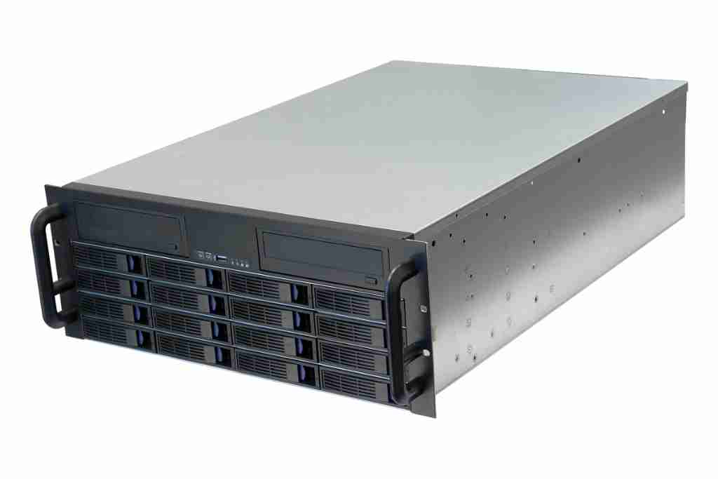
4U 16-Bay Hotswap Chassis
ServerCaseUK stocked 16-bay 4U chassis units, so one of these was ordered. These have 4 internal backplanes, with SFF-8087 Mini-SAS connections, so hooking into my existing 16-channel HBA card would be simple. In the current setup, the multi-lane cables are routed out via SFF-8088 connectors to the drive array, so this will tidy things up considerably.
SFF-8087 Connections
The main data links are via these SFF-8087 connectors, each carrying 4 lanes of SATA.
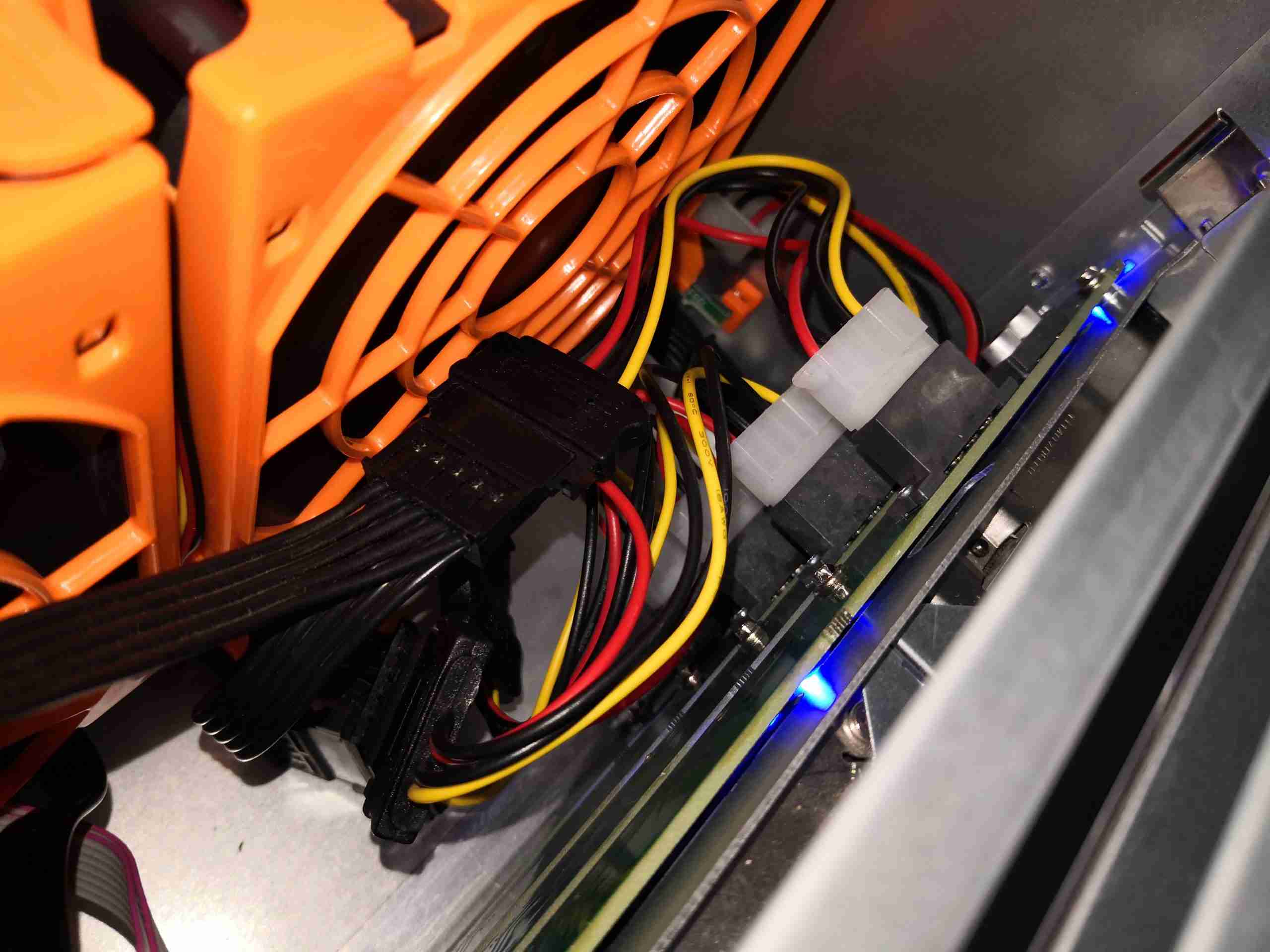
Backplane Power
Power is provided by 4x Molex connections, via SATA power adaptors (the good kind, which don’t create fire). There’s a 5th Molex hidden down the size of the last fan, which powers all 3 120mm fans.
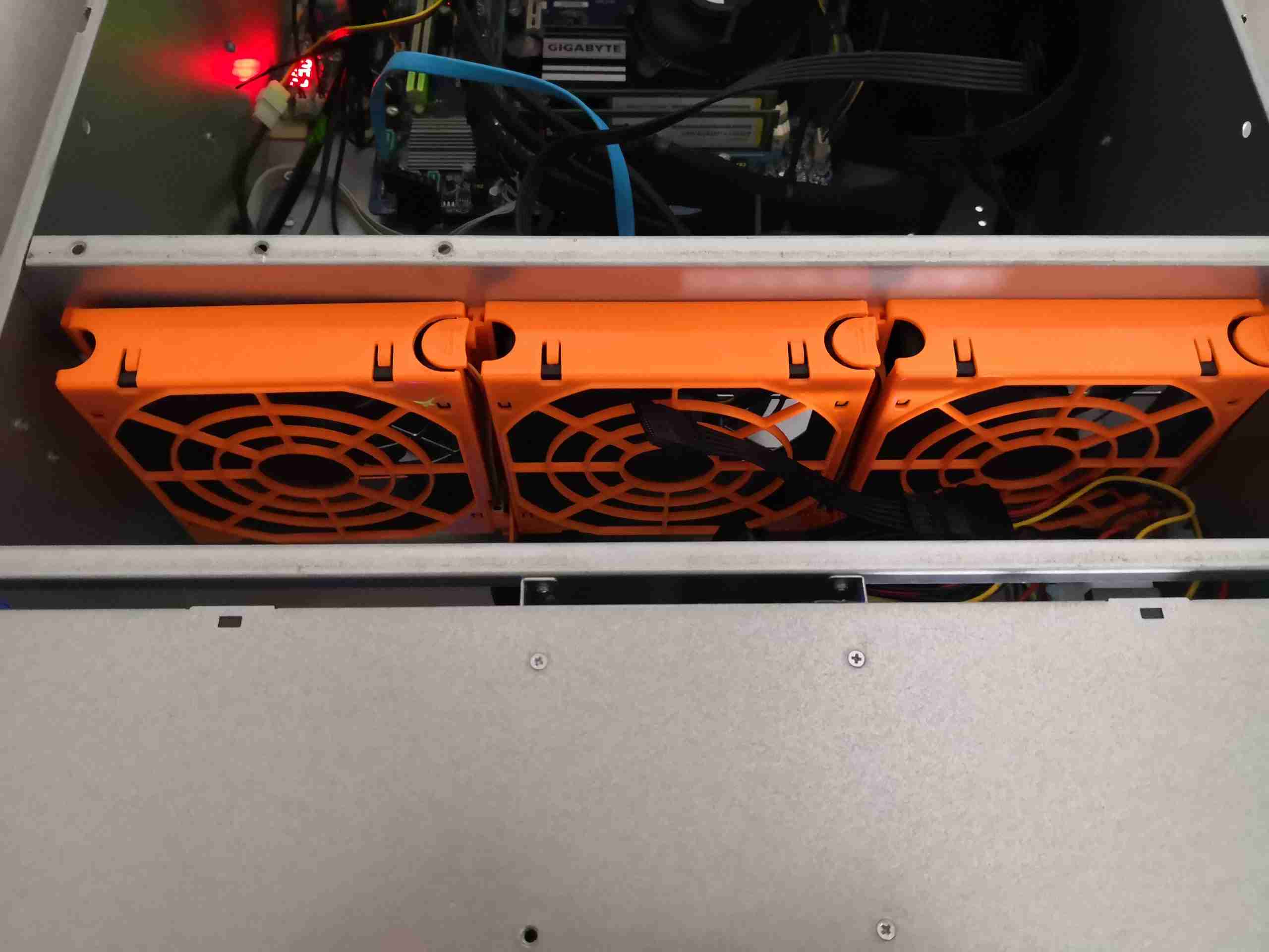
Disk Array Fan Wall
The disks are kept cool by 3x 120mm hot-swap fans on the dividing wall. These don’t create much noise, and are always at full speed.
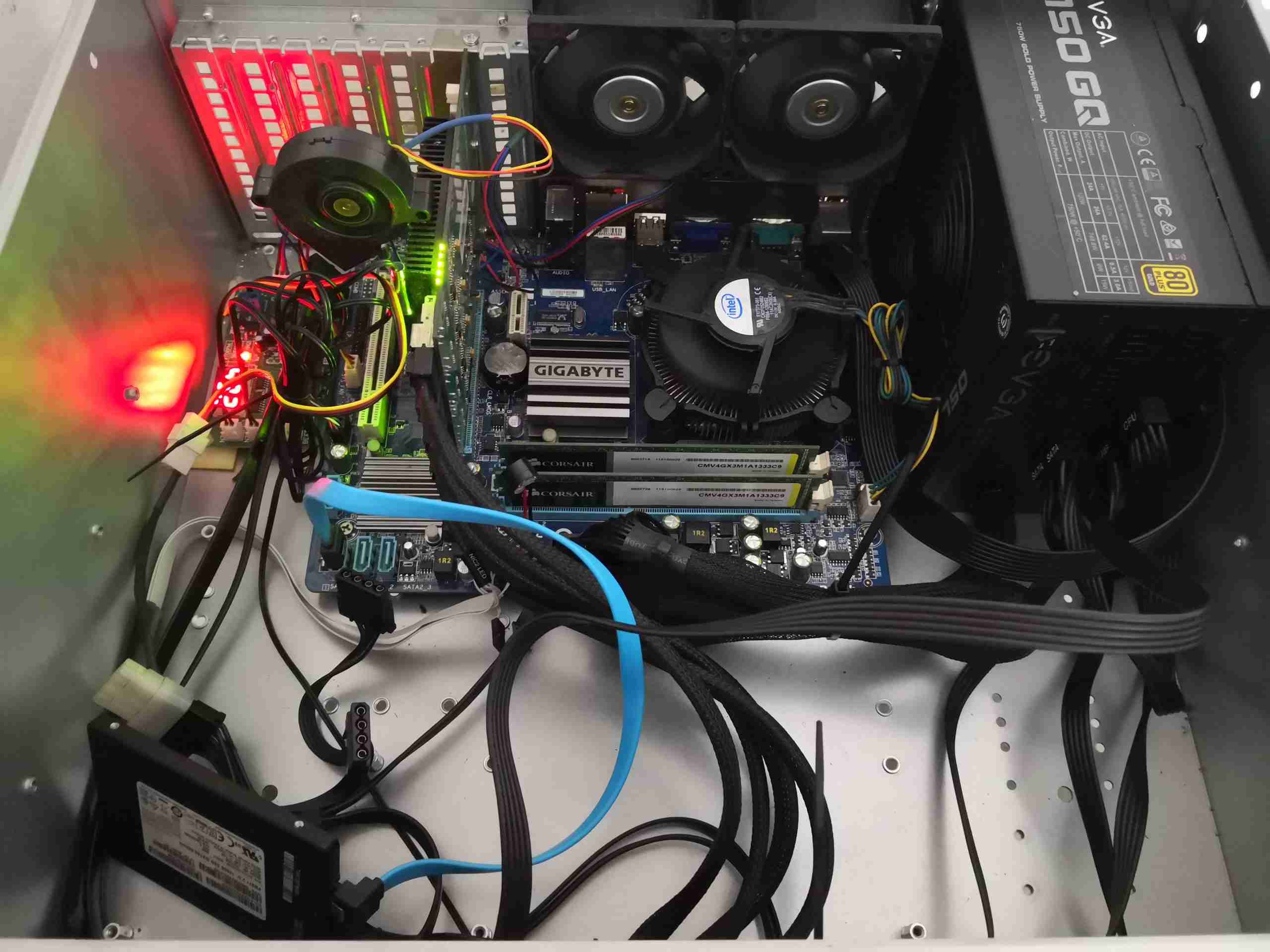
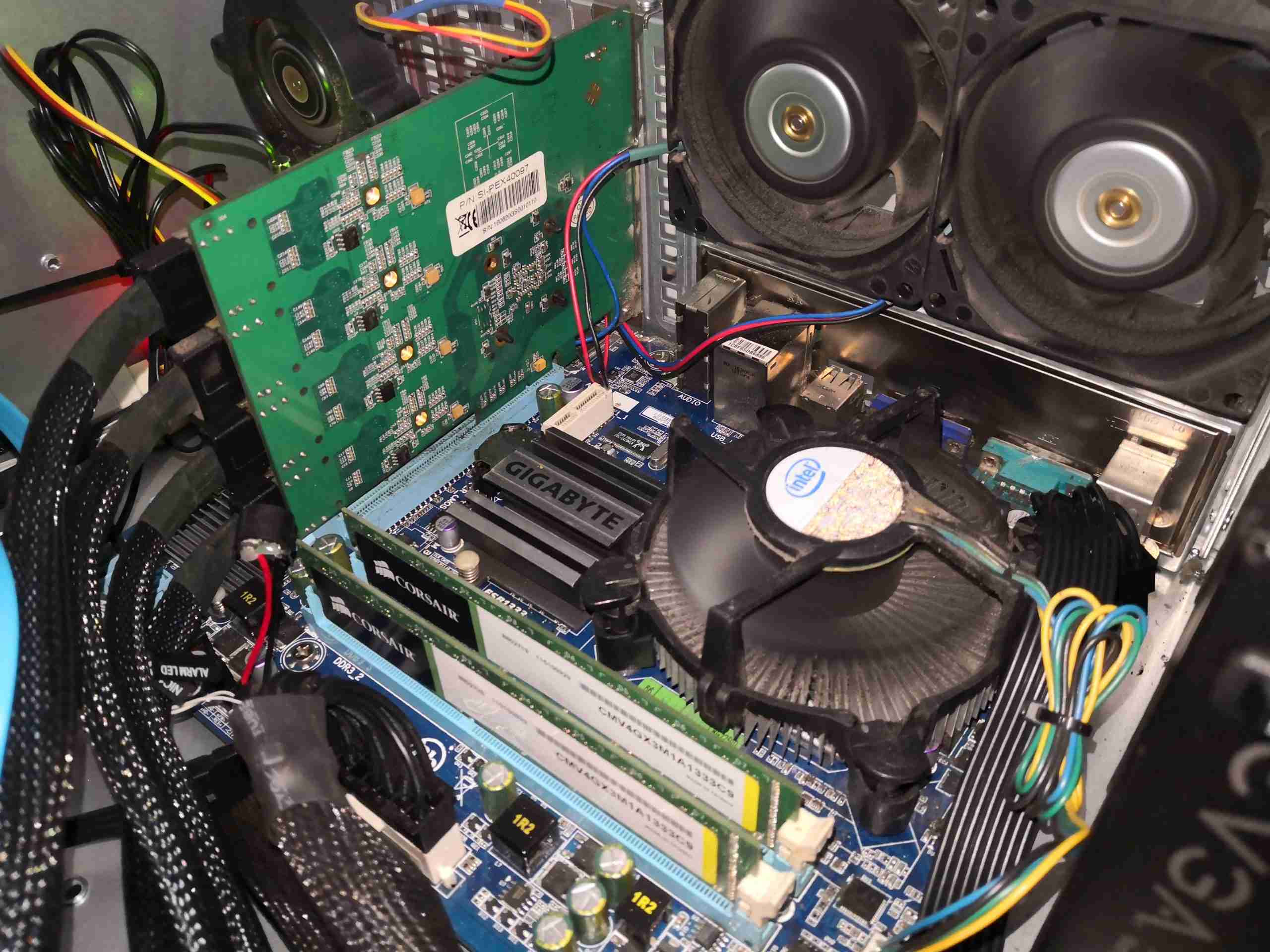
Motherboard Bay
Here’s the back of the case after transplanting the motherboard & HBA from the old chassis. There’s a new 750W EVGA modular power supply, since I’ll be expanding the disk array as well. The boot SSD is currently sat on the bottom of the case since I don’t have a data cable long enough to mount it in the proper place as yet.
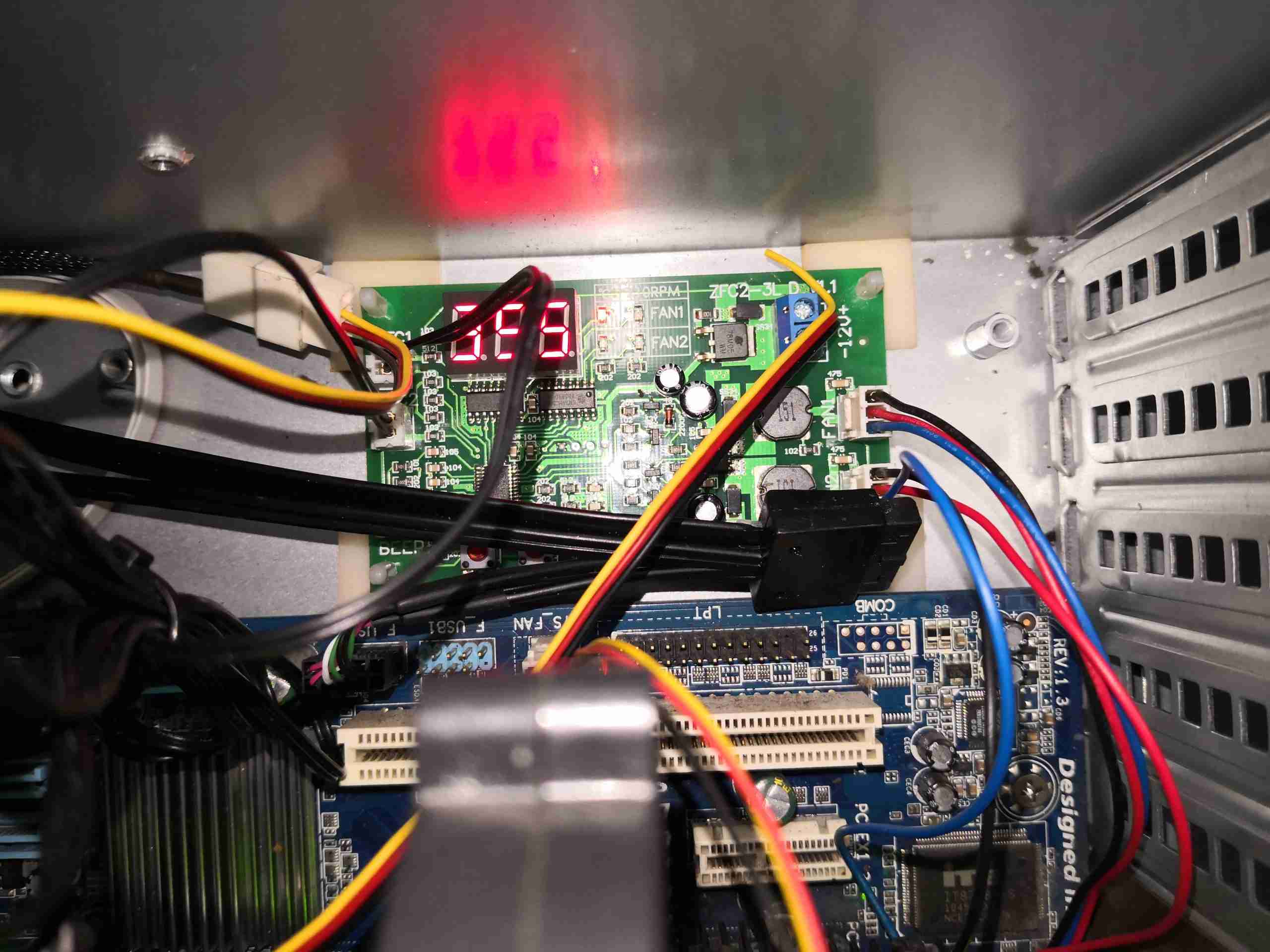
Fan Controller
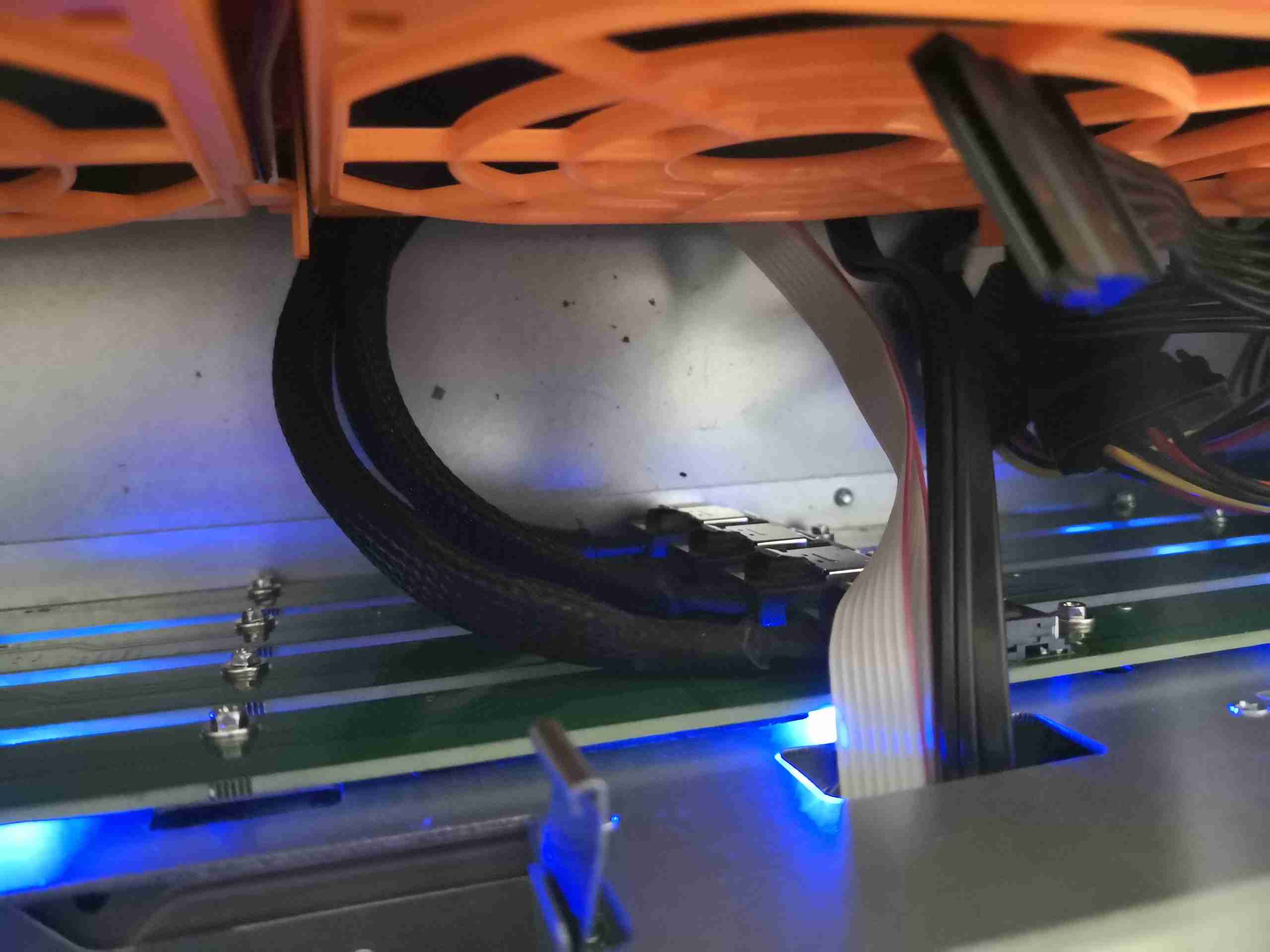
Here’s the fan controller, which takes care of the dual high speed Delta fans on the back wall of the chassis. This has a pair of temperature sensors – one on the HBA card’s heatsink, and the other on the fan wall monitoring the exhaust air temp of the drive array, to control the speed of the two fans. Temperatures are kept at around 30°C at all times.
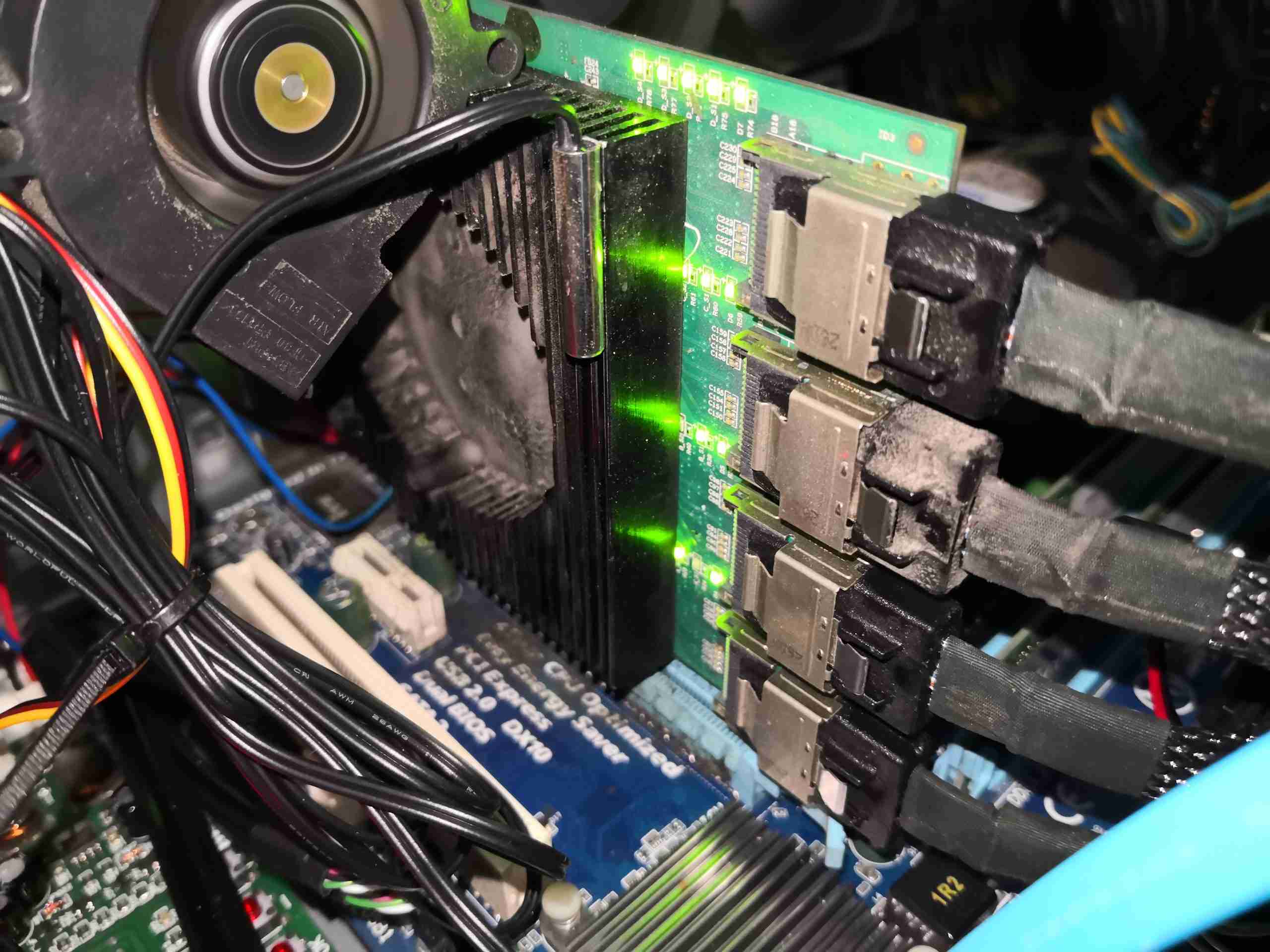
16-Port SATA HBA
Since the HBA card’s fan failed a while back, it’s had a couple of fans attached. The centrifugal one here works a little better than a massive 80mm axial fan, and is a little quieter. This is always run at full speed from a spare motherboard header. The temperature sensor feeding the fan controller can be seen here bonded to the heatsink. The 4 SFF-8087 cables are going off to the disk backplanes.
Cooling
As mentioned before, there are a pair of 80mm Delta high-speed fans on the back wall of the case, to provide some extra cooling air flow just in case overheating manages to set in. These are usually spooled down to low RPM to keep them quiet.
Since space was getting a little tight, and having some slots spare on the HBA, I decided to add some more disks to bring the active members up to 12, from 9 – increasing available disk space from 28TB to 40TB.
/dev/md0:
        Version : 1.2
  Creation Time : Wed Mar 11 16:01:01 2015
     Raid Level : raid6
     Array Size : 39068874880 (37258.98 GiB 40006.53 GB)
  Used Dev Size : 3906887488 (3725.90 GiB 4000.65 GB)
   Raid Devices : 12
  Total Devices : 13
    Persistence : Superblock is persistent

  Intent Bitmap : Internal

    Update Time : Mon Nov 18 14:13:35 2019
          State : active
 Active Devices : 12
Working Devices : 13
 Failed Devices : 0
  Spare Devices : 1

         Layout : left-symmetric
     Chunk Size : 64K

           Name : Main-PC:0
           UUID : 266632b8:2a8a3dd3:33ce0366:0b35fad9
         Events : 1653174

    Number   Major   Minor   RaidDevice State
      16       8      144        0      active sync   /dev/sdj
      11       8      160        1      active sync   /dev/sdk
       9       8      176        2      active sync   /dev/sdl
      10       8      208        3      active sync   /dev/sdn
      15       8      192        4      active sync   /dev/sdm
       5       8      112        5      active sync   /dev/sdh
       6       8       80        6      active sync   /dev/sdf
      13       8       96        7      active sync   /dev/sdg
       8       8       64        8      active sync   /dev/sde
      19       8        0        9      active sync   /dev/sda
      18       8       48       10      active sync   /dev/sdd
      17       8      128       11      active sync   /dev/sdi

      12       8       16        -      spare   /dev/sdb
The space expansion improves things there, I will be adding a couple more spare disks to bring the number up to the full 16, just in case of any failures.
There are still a couple of issues with this setup:
The motherboard & CPU are ancient. Currently an Intel Core 2 Quad, running 8GB of RAM, limits data throughput, and critically, the speed of mdadm data checks & rebuilds. The Core 2 Quad also runs at roughly the same temperature as the Sun’s core when under high load.
The SATA HBA is running 4 controllers on an expander, through a PCIe x4 link, which is a little slow due to congestion on the expander itself. RAID6 does have some write-speed penalties though.
These are issues I will address shortly, with a replacement motherboard on the way!
While we’re away camping, be it at a festival or general site, it would be nice to have a relatively efficient fridge to store food & drink in, so I set to work assessing the requirements. Commercially supplied 12/24v fridges are hella expensive – running between £450-£700 for even a small compressor coolbox! So in my general style, I figured it was time to get building my own, integrated into the current system. With the bonus of learning some things along the way. There are some refrigerants that aren’t covered under the F-Gas regulations, such as R600a (Isobutane) & R290 (Propane), so I can easily avoid those legal requirements, not to mention being a little more environmentally conscious. The common Danfoss BD35F compressors are designed for R-134a, but there are equivalent replacements available for the automotive AC market that operate within the same pressure ranges. As far as I can tell, these replacements are mixtures of R600a & R290 in various proportions.
I decided to keep most of the weight, control & wiring internal to the main power trolley which goes everywhere with us while camping, this obviously required the refrigerant lineset to be dis-connectable from the fridge cabinet for transport, and has the requirement for a flexible lineset between the two. The marine-grade refrigeration systems destined for custom builds are supplied with dis-connectable copper linesets with special fittings, so I went in search for a supplier of said fittings. The need for flexibility & re-usability means I can’t use the copper lines in this application – work hardening will quickly cause the copper pipe to crack.
Parker-Hannifin supply these special fittings, and seem to be the original manufacturer – considering they specialise in fluid power & control, this isn’t a surprise. However ordering from them is a nightmare, so no go there. I did find an Italian supplier of equivalent fittings, the Faster Coupling RF series:
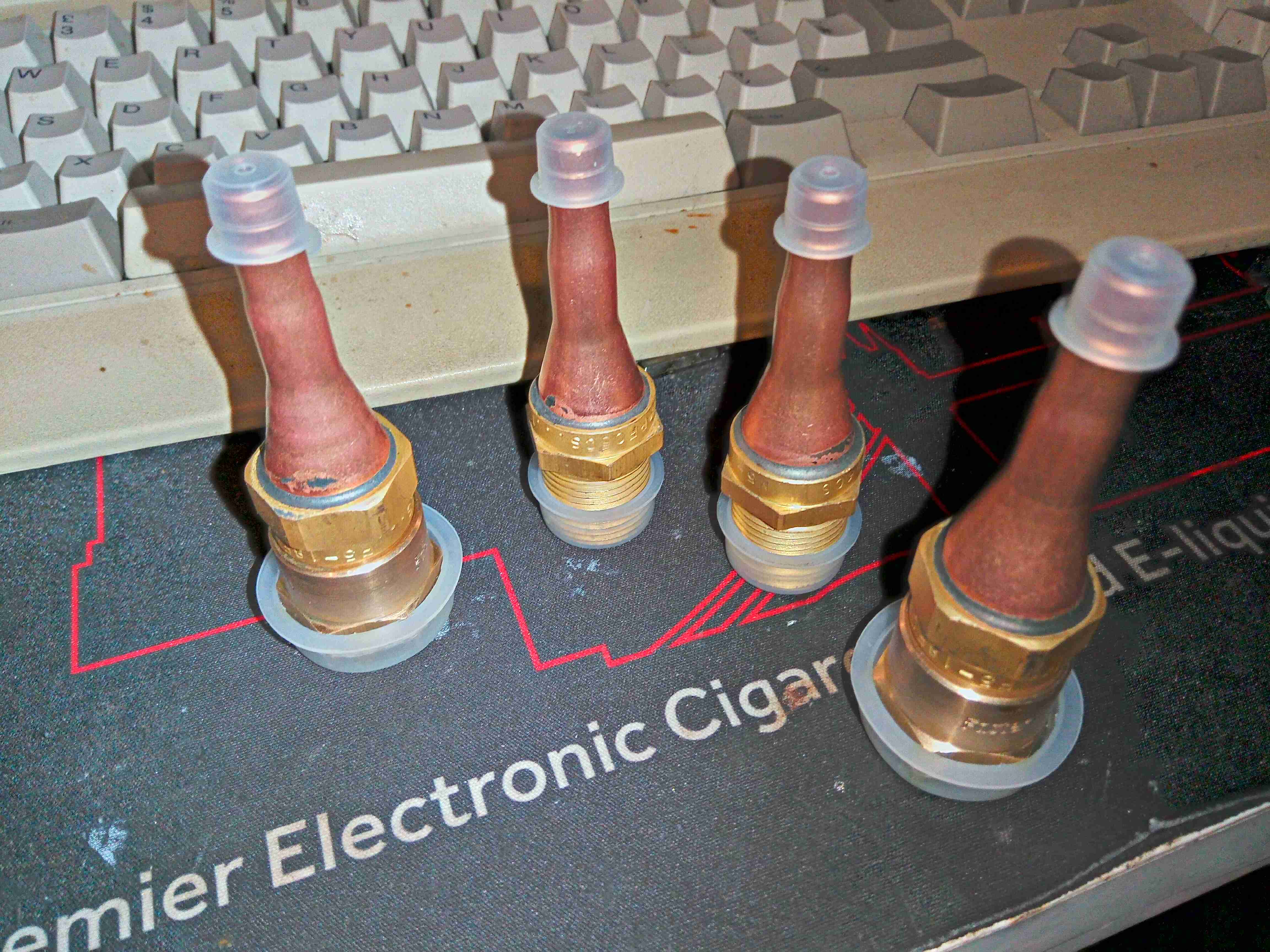
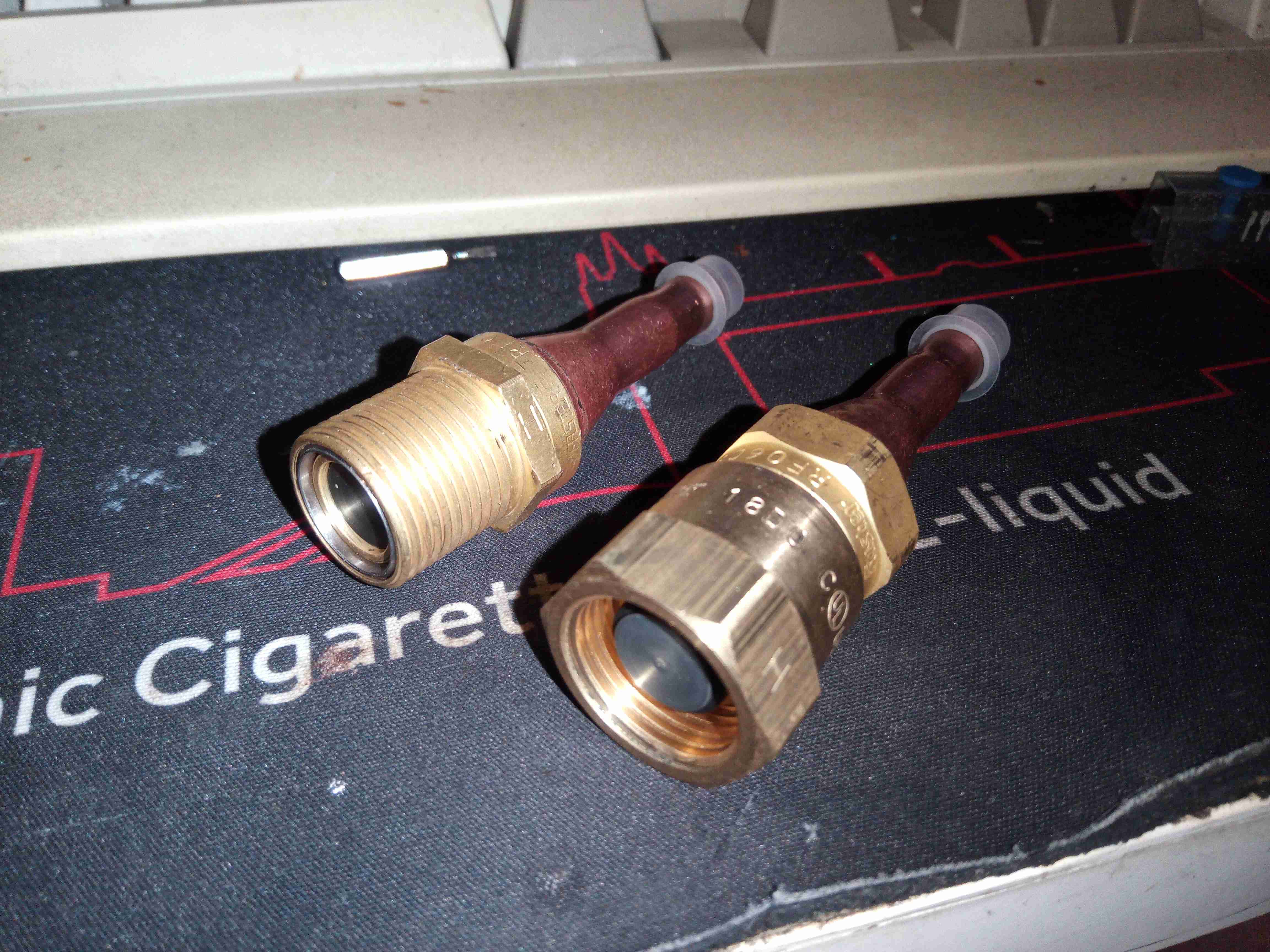
Lineset Disconnect Fittings
Luckily, I was able to get a distributor in the UK to order these in for me, but they are a bit expensive, at ~£130 for two pairs. I sized these for 1/4″ to match the compressor lines. They’re quite well made from brass, with copper tails silver-soldered for braze connections.
Fitting Pair
The fittings screw together like hydraulic couplings, however these are designed for very low leakage, and very low admission of air when connecting them together.
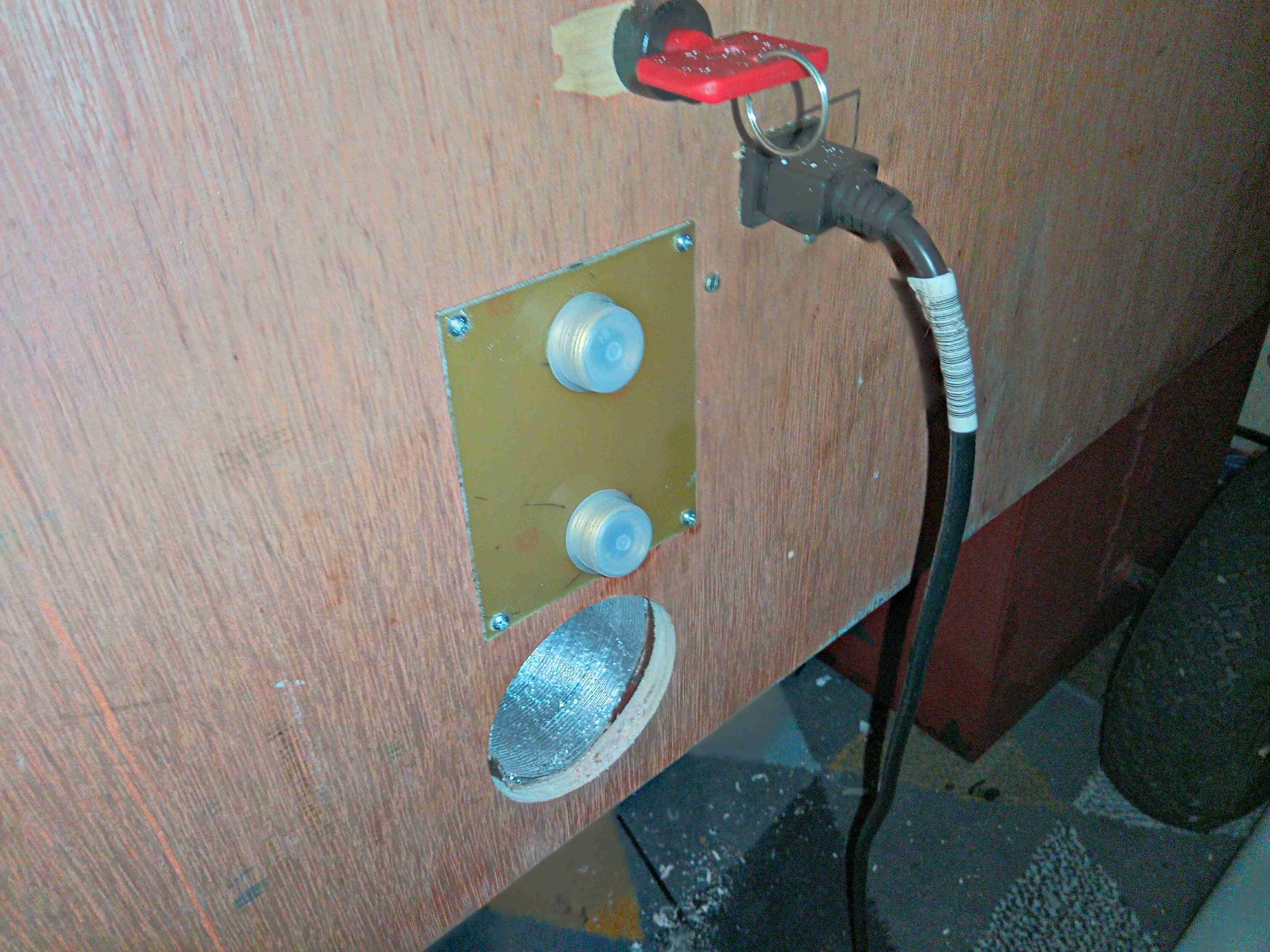
Fitted To Frame
Time to get these panel mounted on the back of the power trolley. The 1/2″ plywood frame is too thick to mount these directly, so I had to improvise a mounting plate:
Fitting Mounting Plate
A bit of FR4 PCB material with suitable holes bored makes for a nice thin panel with high strength. I will colour-code these to make sure the suction & discharge lines aren’t mixed up when connecting, considering they’re both the same size.
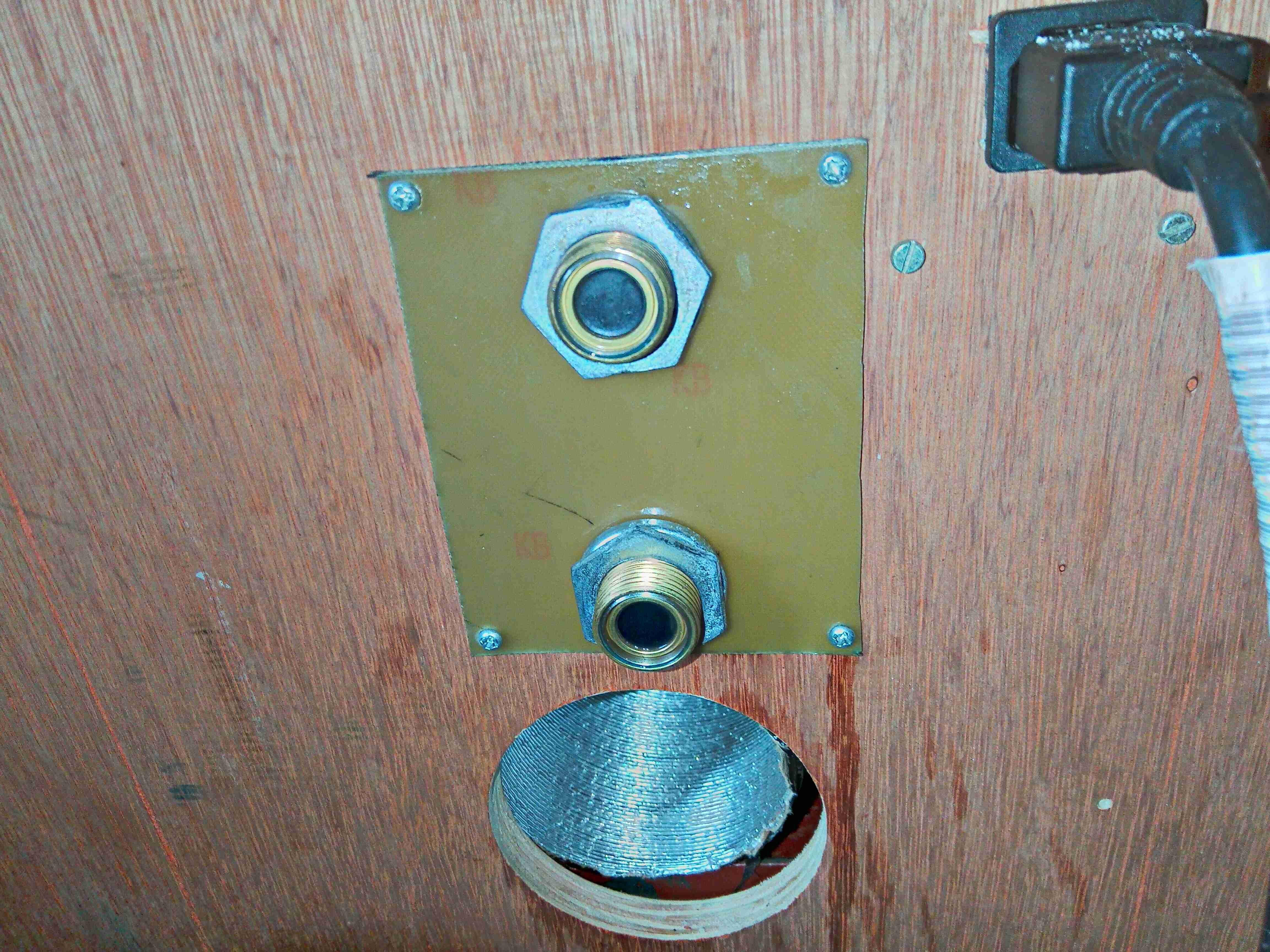
Refrigerant Fittings
The fittings are secured with M20 conduit nuts & spring washers.
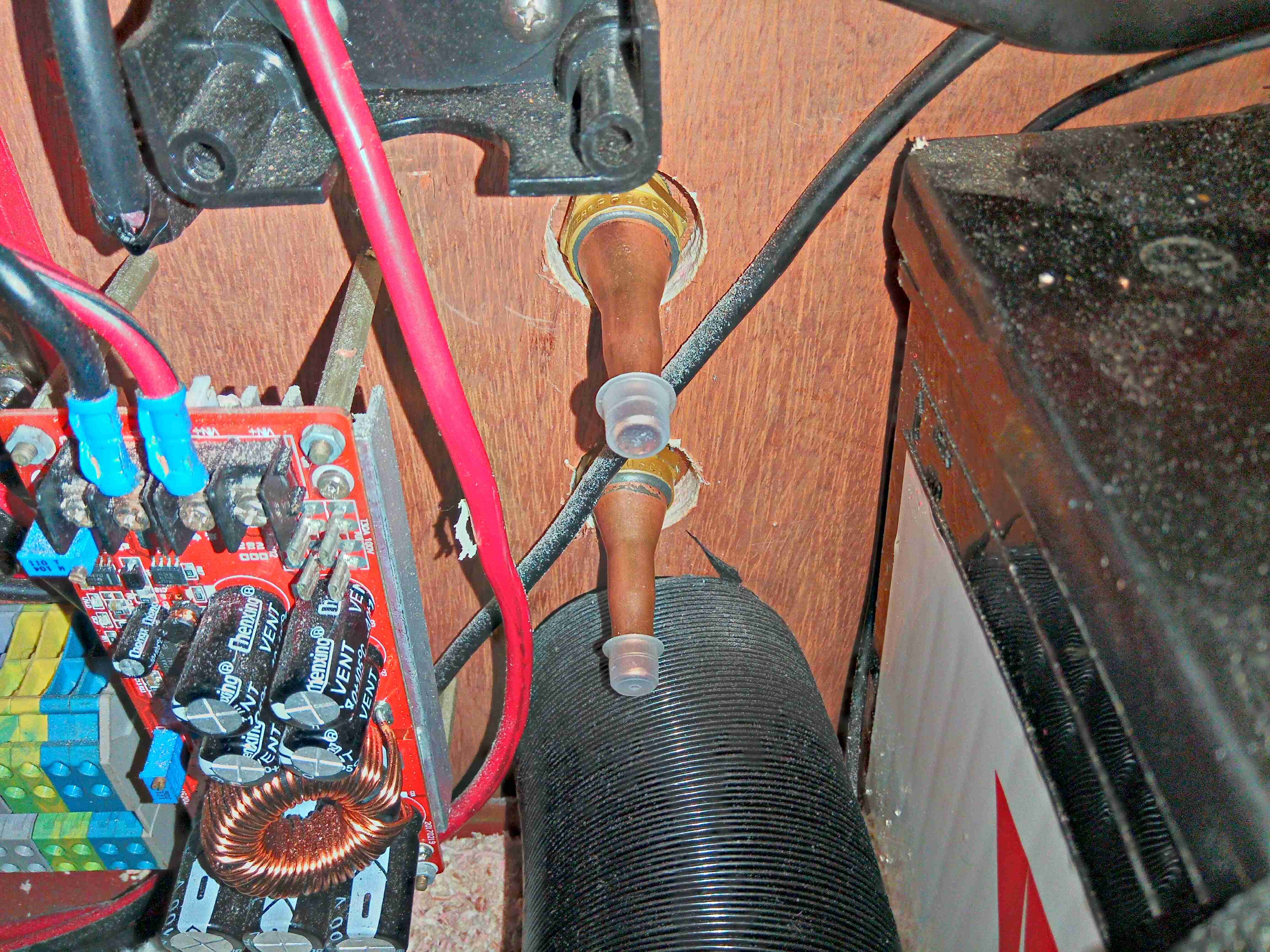
Compressor Unit
Here I’ve got the compressor fitted & all the lines brazed, and have the system under vacuum to get any traces of water out. Side note: the RF series couplings are *very* difficult to braze with just a single burner MAPP torch – keeping the end of the fitting with the rubber seals submerged in water to stop them melting just conducts too much heat away from the copper tail too quickly. I did successfully manage to get them brazed though, and this section of the system holds both vacuum & pressure to 12 bar. The condenser coil is mounted underneath next to the fuel tank:
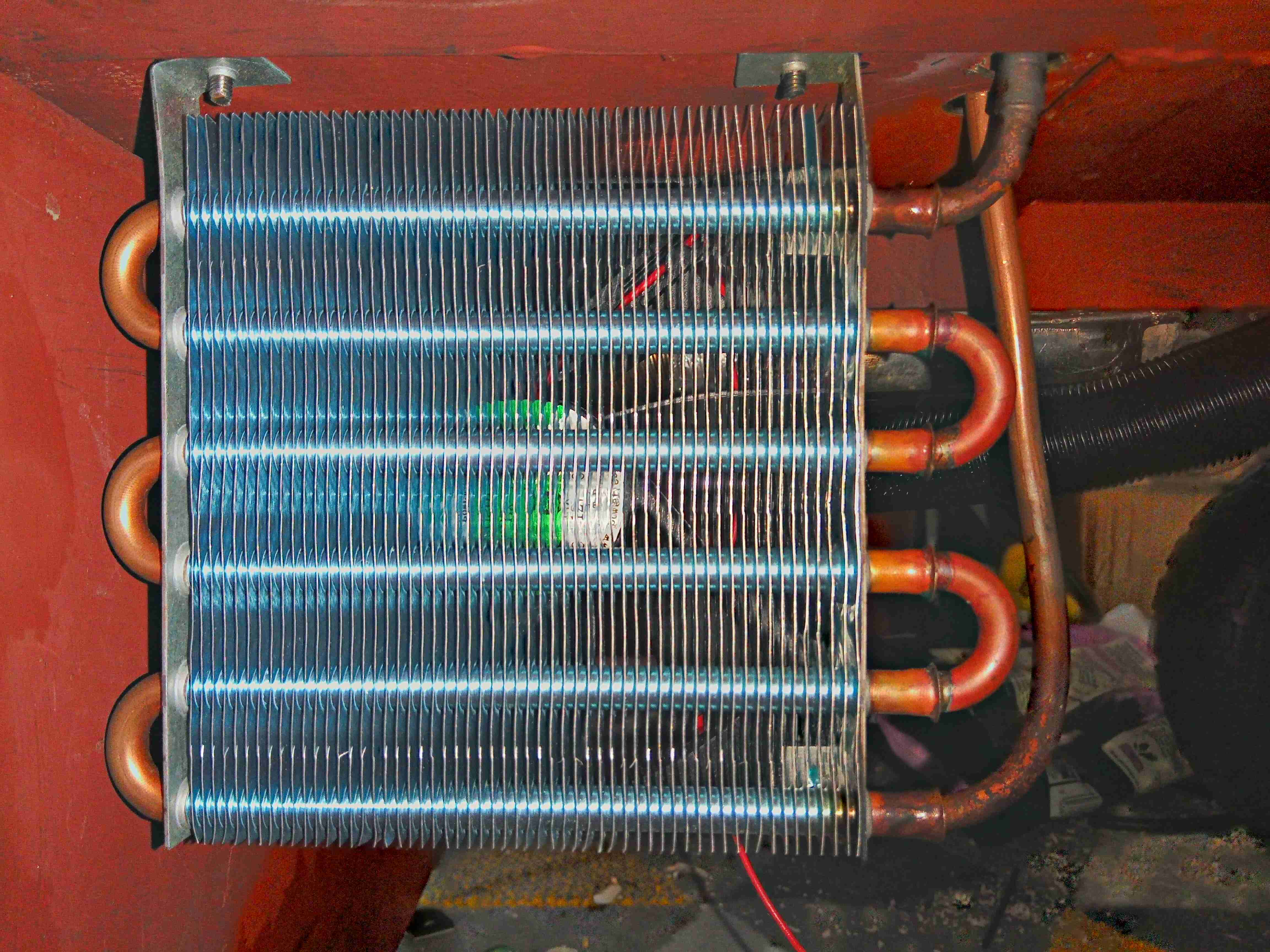
Condensing Coil
There’s a 120mm fan behind for forced air cooling, with the refrigerant lines run up to the compressor above.
I’ll be back soon with the build of the fridge cabinet & evaporator section!
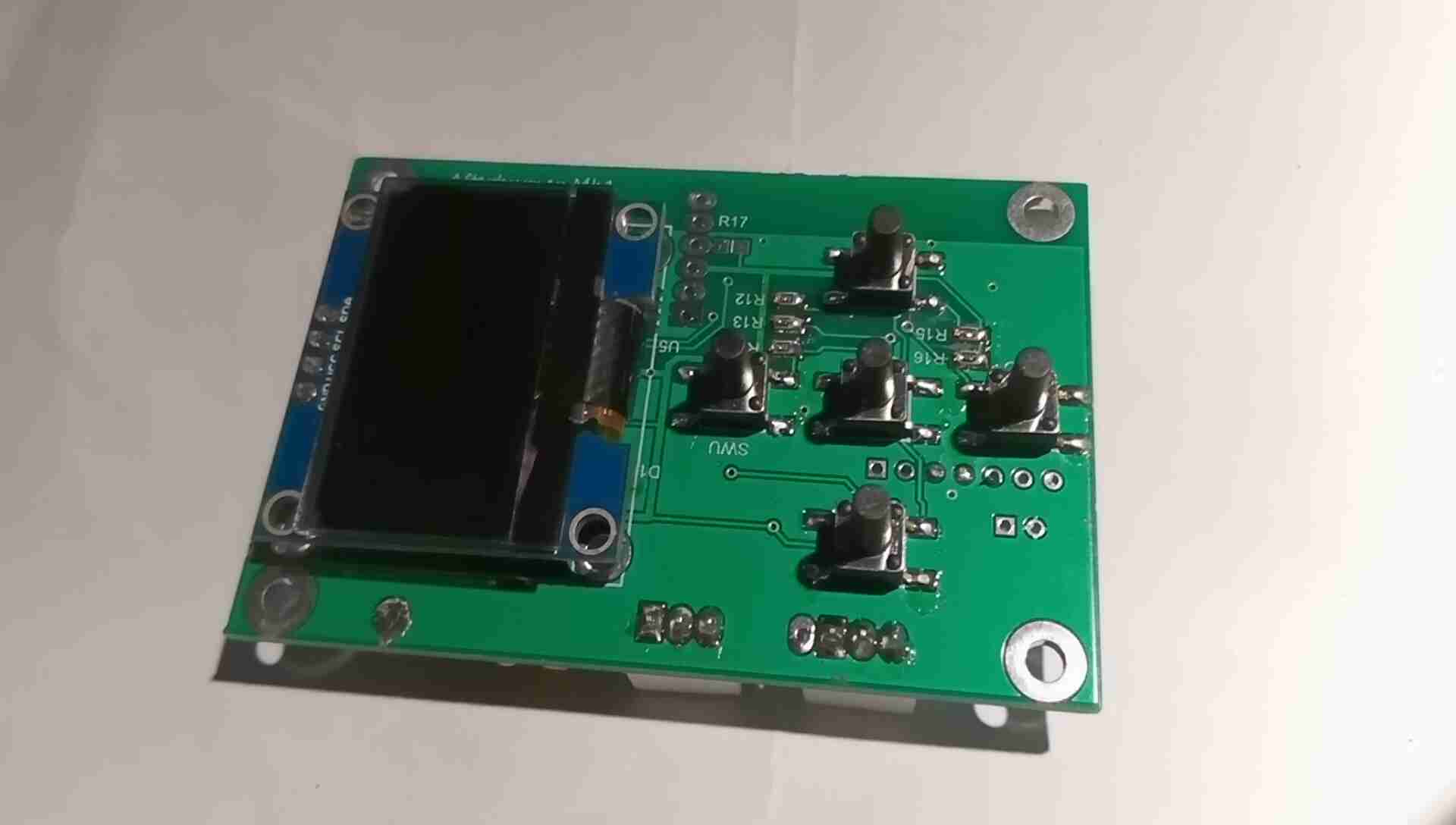
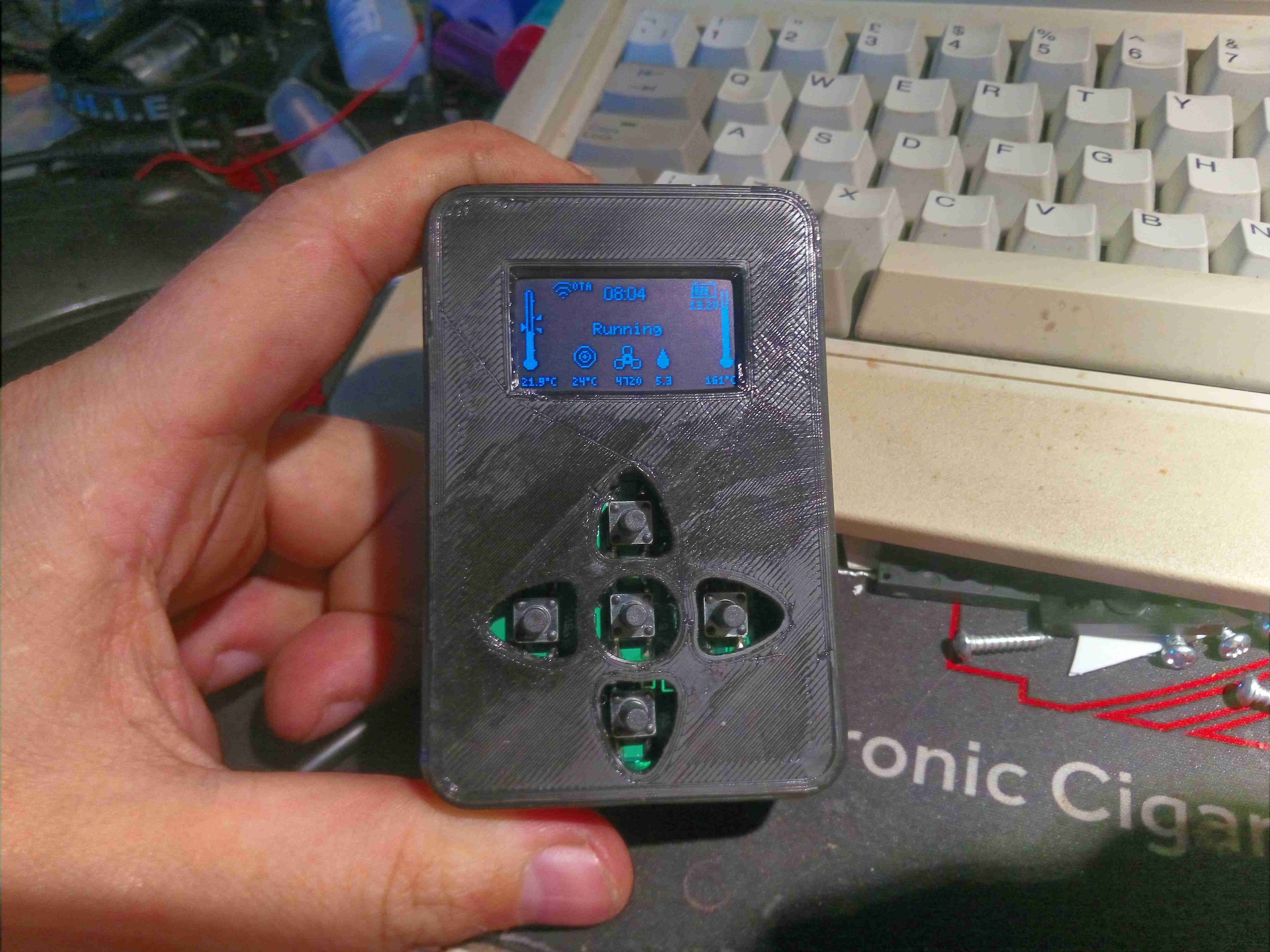
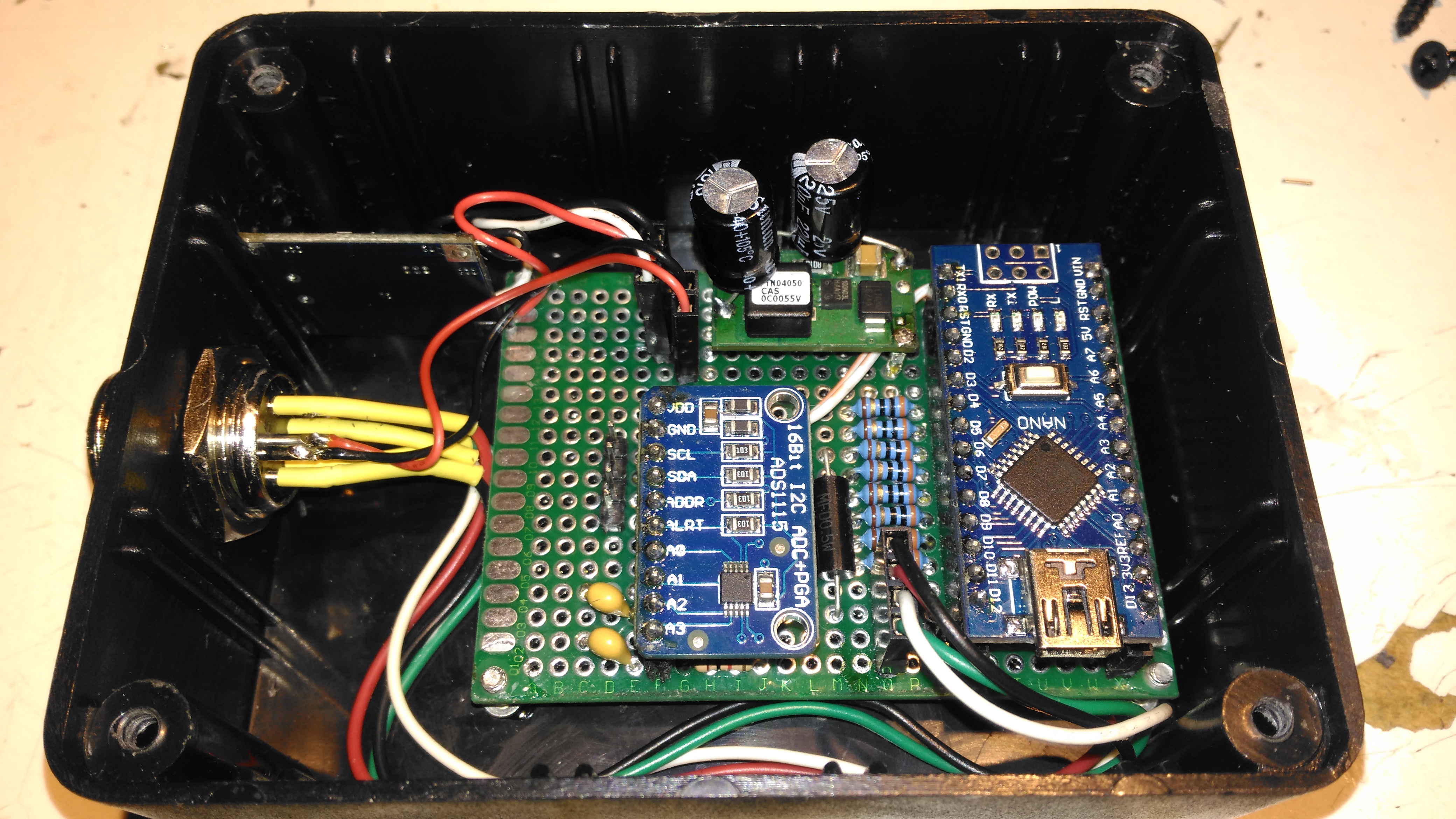
While I’m pretty happy with the Chinese diesel heater replacement for the old Eberspacher on the trolley, the stock controller leaves much to be desired. While functional, it’s fairly unresponsive, bulky & doesn’t allow external control as the Eberspacher did with it’s simple ON/OFF signal. So after a massive amount of searching on the web, (it wasn’t easy to find, damn SEO!), I discovered a project by a chap in Australia who has reverse engineered the communications protocol of these heaters, & built a fully custom controller. This is based around the ESP32 Wi-Fi microcontroller, and a Bluetooth HC-05 module. Display is by means of a 1.3″ OLED screen.
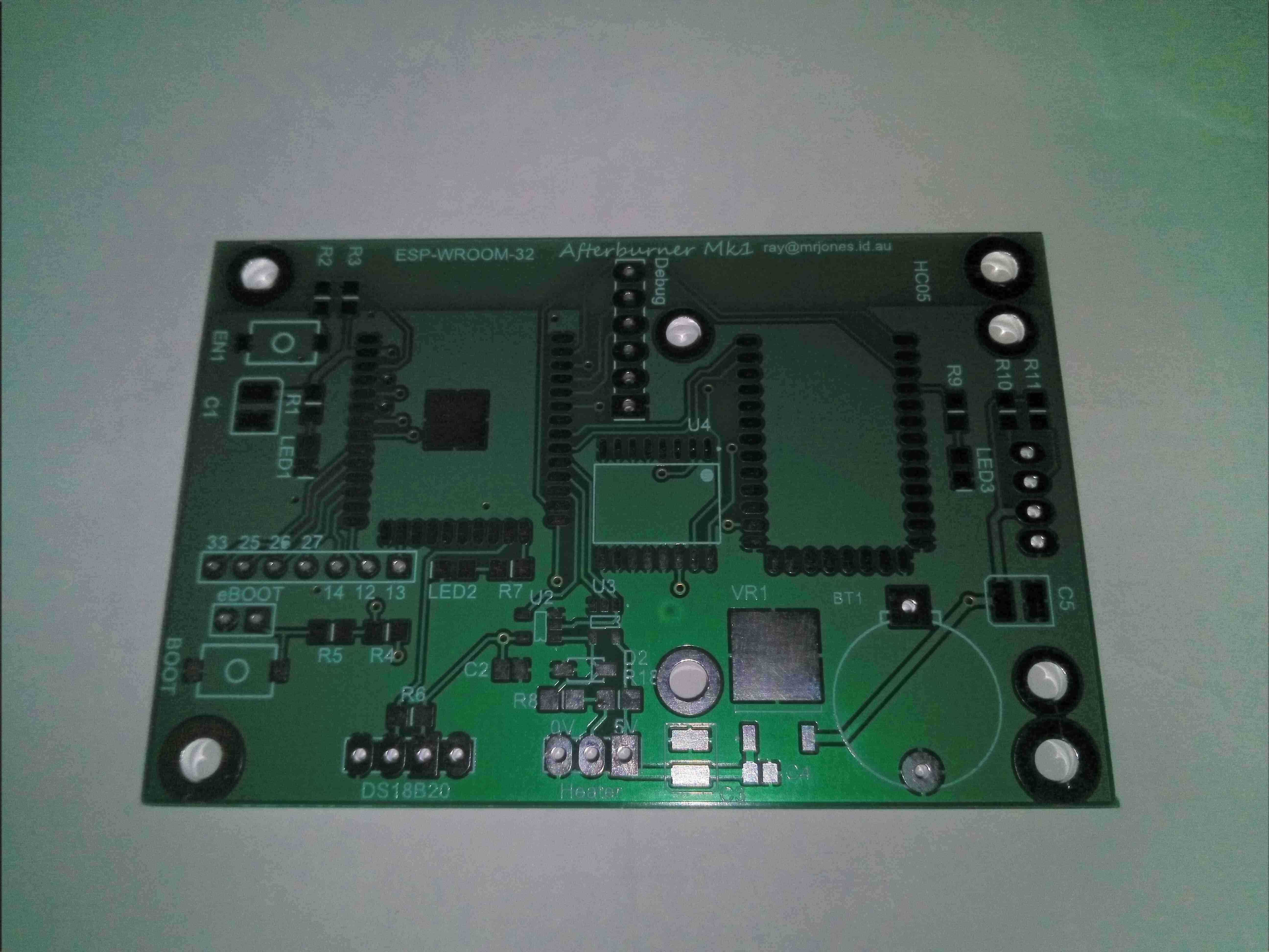
Bare PCB
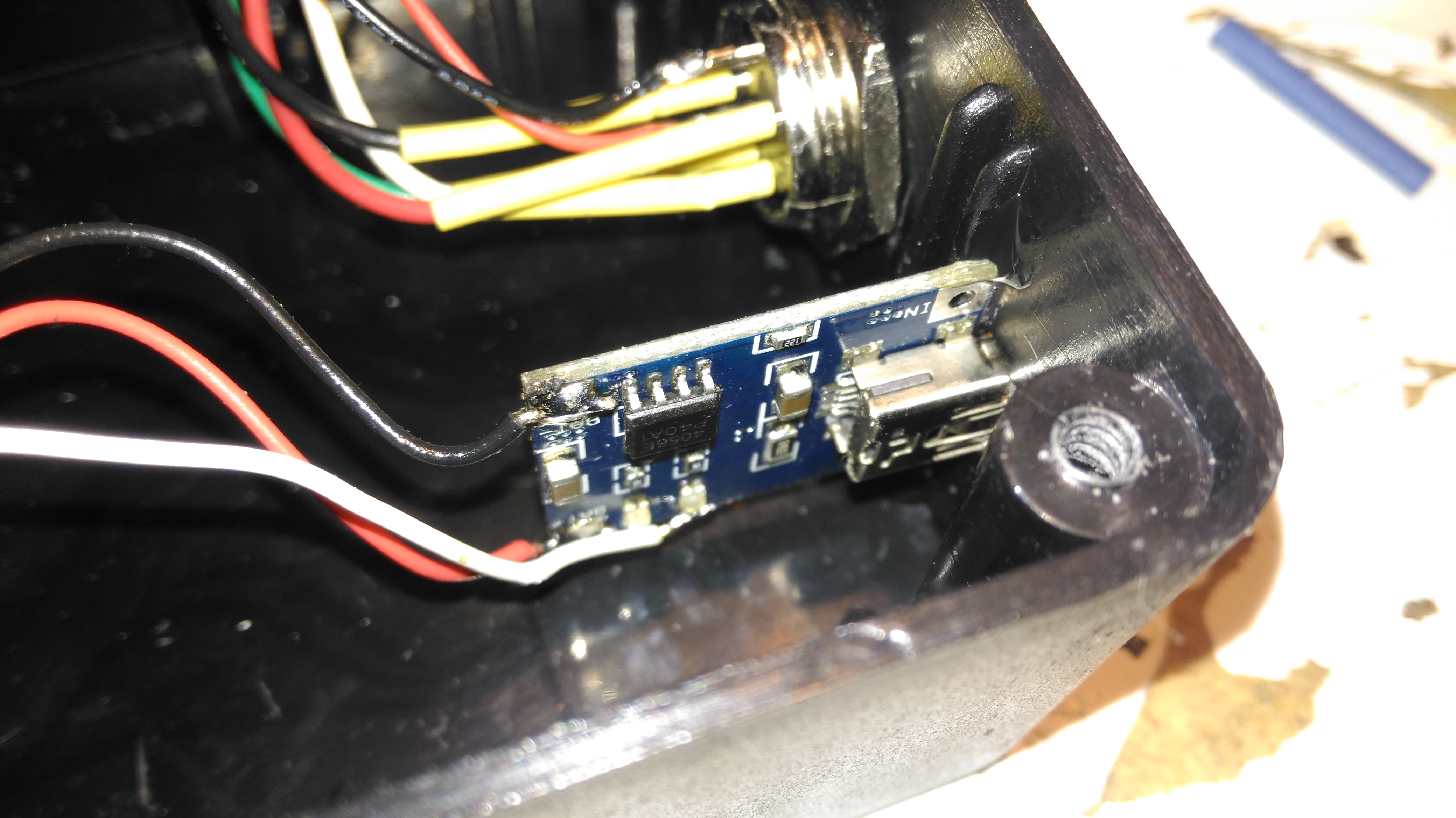
Here’s the bare PCB kindly sent to me by Ray down under to get this project kickstarted. No THT components here apart from headers, everything is minimum 0805 size.
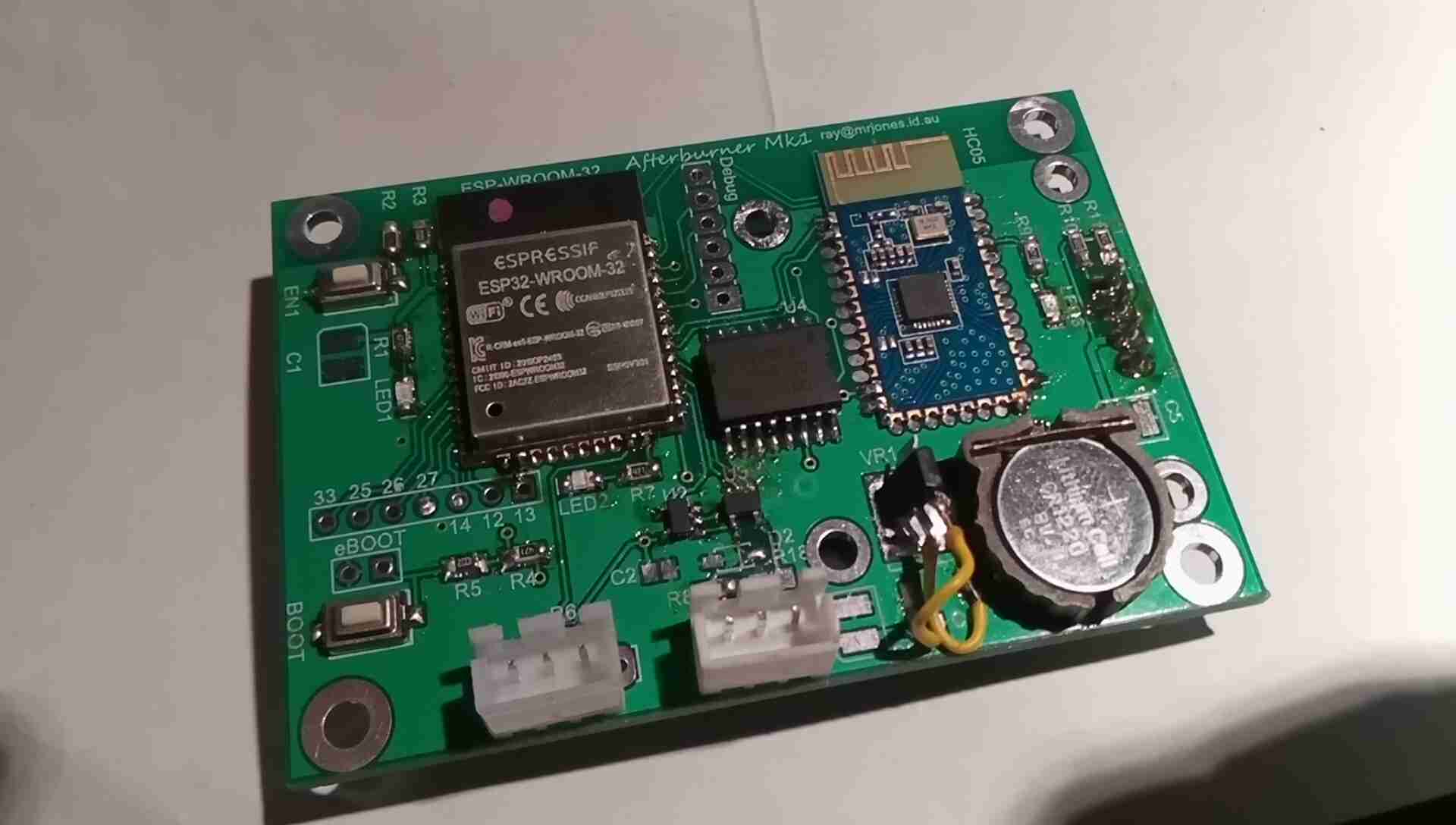
Populated PCB
Here’s the controller PCB fully populated, with the ESP32 & Bluetooth HC-05 modules on board. There was a slight issue with the 3.3v regulator not matching the pinout of the PCB, so some minor bodge work required there, but the current draw of the unit is so low that the regulator doesn’t get warm, even with the heatsink tab floating in mid-air. I’ll hot-snot this down to avoid any vibration issues. Incedentally, soldering the castellated connections of the modules is a real pain – problems with contacts not wetting first time were an issue here. Use plenty of flux!
The two JST connectors are for the main heater loom, and an external temperature probe that feeds back for the thermostat mode of the controller. Reset & Bootloader buttons are provided on the board for easy firmware loading. There’s also some spare GPIO broken out for other uses, along with the required UART port for firmware & debugging access. The clock is maintained by a DS3231 RTC IC, which oddly enough is expensive on it’s own – buying an Arduino RTC module & using a hot-air pencil to desolder the IC worked out £4 cheaper than buying the IC direct! The RTC is backed up by a lithium coin cell.
The communications interface is taken care of by a couple of single gates in SOT-23 packages, which interfaces the 3v3 ESP32 with the 5v signalling levels of the heater’s control bus. This unit is a little odd for a communications interface – it is standard serial, but at an odd baud rate of 25,000, and instead of separate TX & RX lines, the transmissions are gated for TX & RX down a single wire. I fail to understand the logic of doing this, since wire isn’t expensive & extra components just add complexity!
A couple of build notes on this controller:
R4 & R5 are swapped on the silkscreen. Bootloader issues ensued!
The blue PCB Bluetooth module doesn’t function correctly with the controller, allowing receive but no transmit. Odd.
There are two pinout variations on the 1.3″ OLEDs. This layout requires the GND pin leftmost.
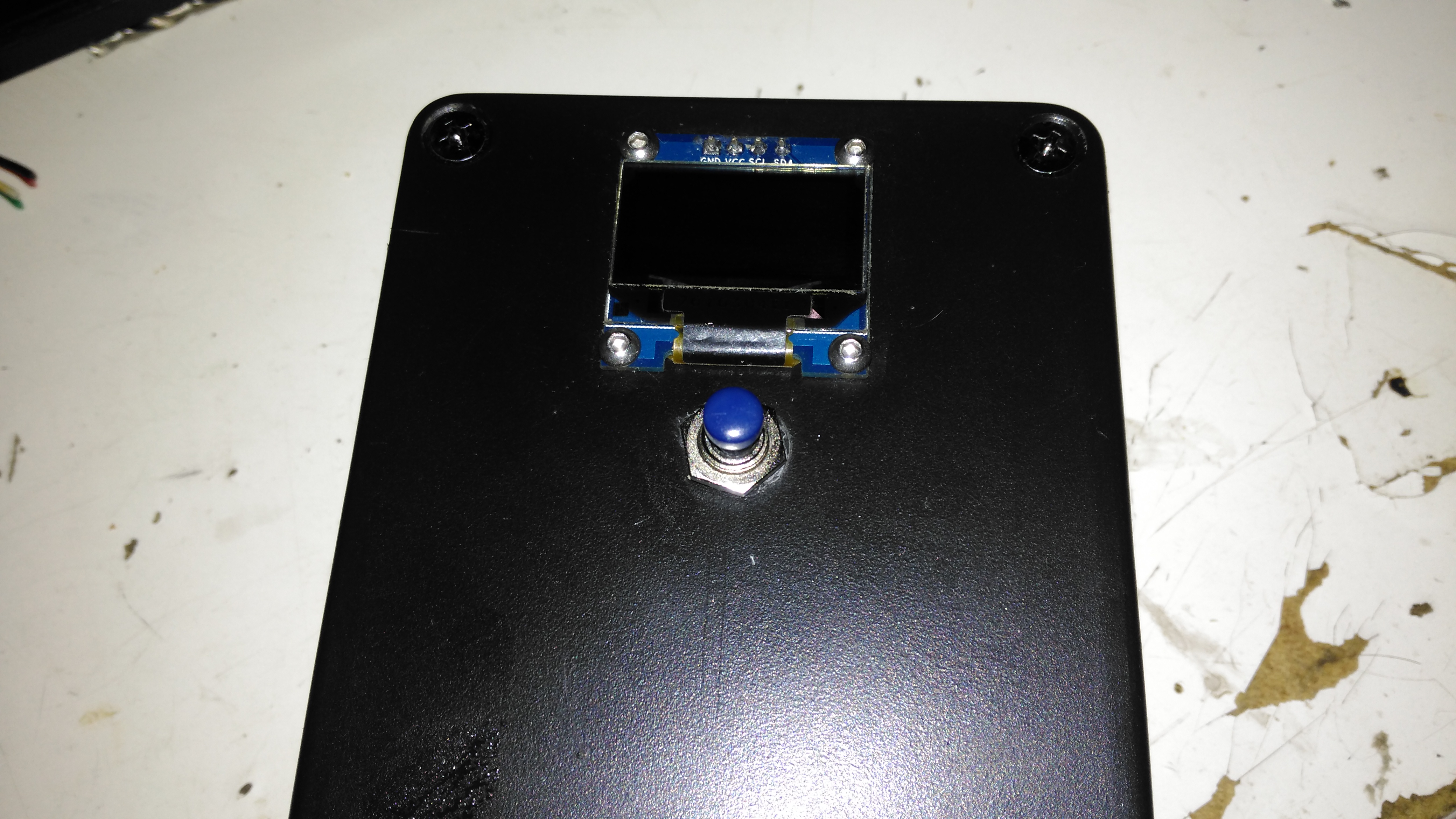
PCB Front
The front of the PCB holds the OLED display panel, and the control button array. Not much else on this side of the board besides the RTC battery switching diodes & some passives.
Glow Plug Heating
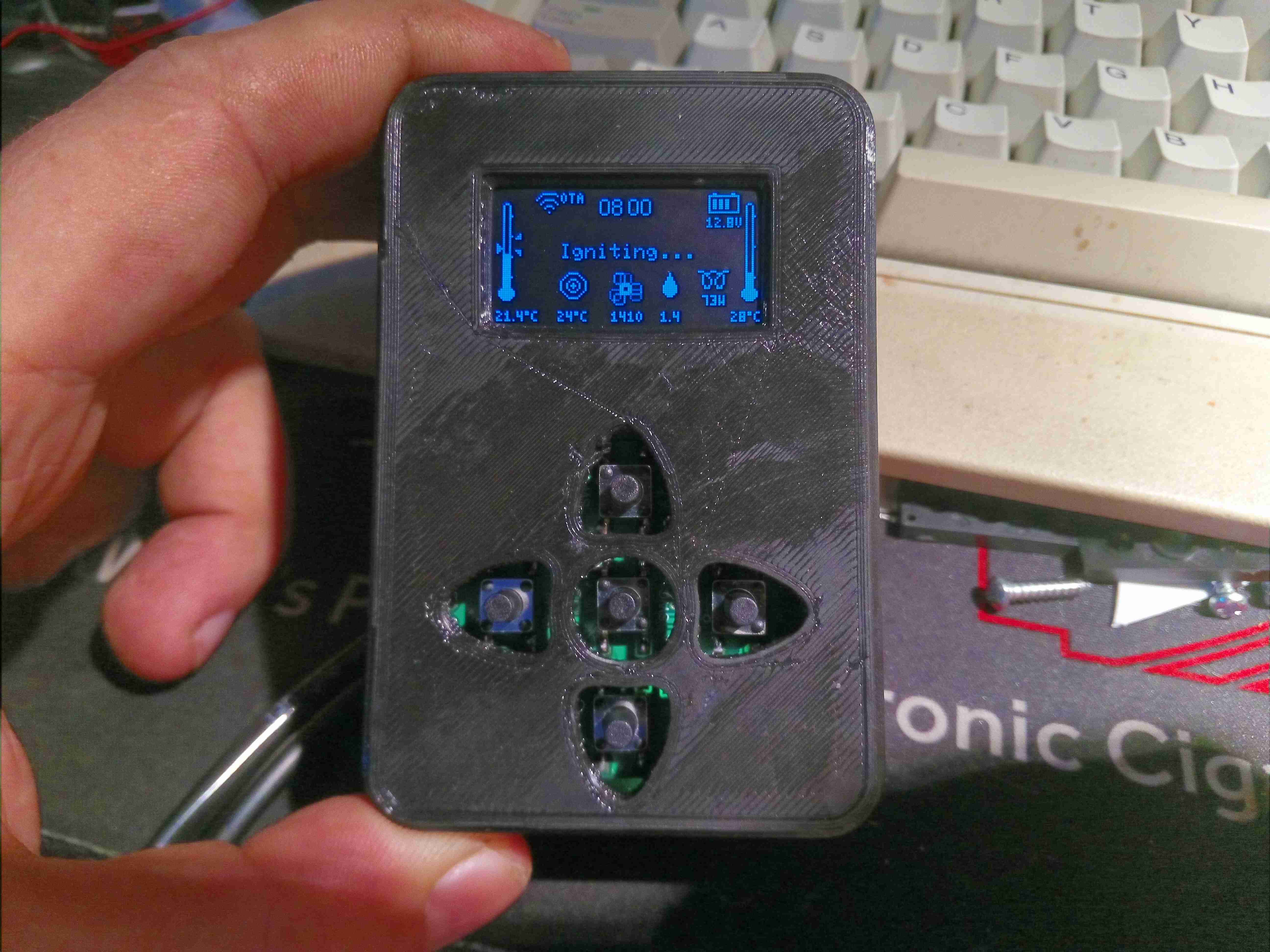
The case to house the PCB is 3D printed, I didn’t bother with the matching buttons as I don’t currently have any flexible filament to print with, so long stem tact switches are used. The controller is running the heater through a cycle here on the Detailed Info screen, where the most comprehensive heater info is displayed. In this stage, the heater’s ECU is warming the glow plug up ready for ignition.
Igniting
After the glow plug has heated, the ECU starts the fuel metering pump at it’s lowest rate to get a flame going. The glow plug is still active to vaporise the fuel.
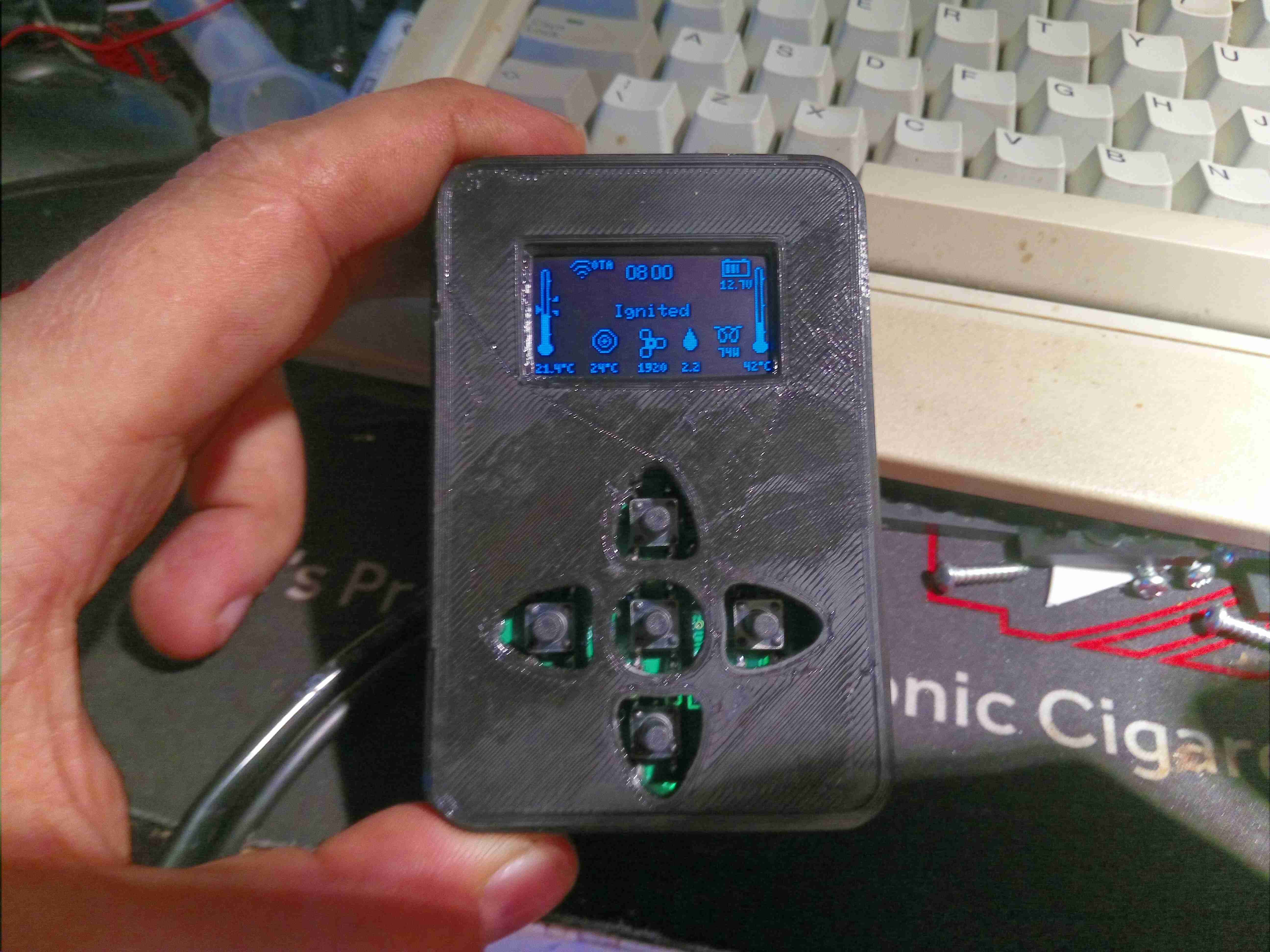
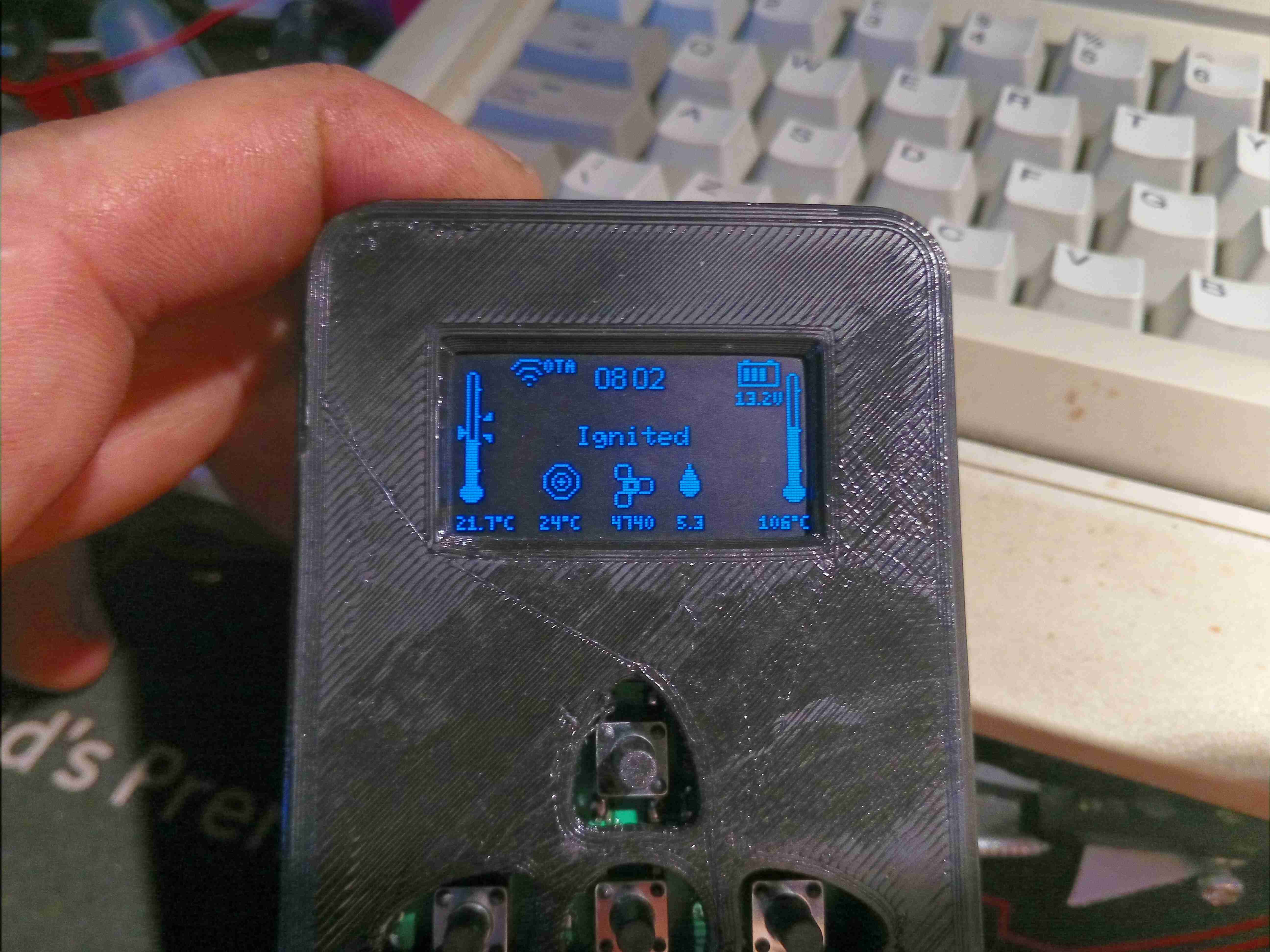
Burner Running – Heatup
Once the thermistor on the heat exchanger registers a temperature increase, the ECU detects the burner has lit, and starts increasing the fuelling rate & blower speed.
Warming Up
Once the temperature hits a threshold, around 55°C, the ECU switches off the glow plug & ramps the fuelling rate up to max to warm the heat exchanger to operating temperature. The detailed page displays both the room temperature (left), set temperature & heat exchanger temperature (right).
Heater Running
Once the heat exchanger has reached running temperature, the ECU switches control to the thermostat, in this case the new controller.
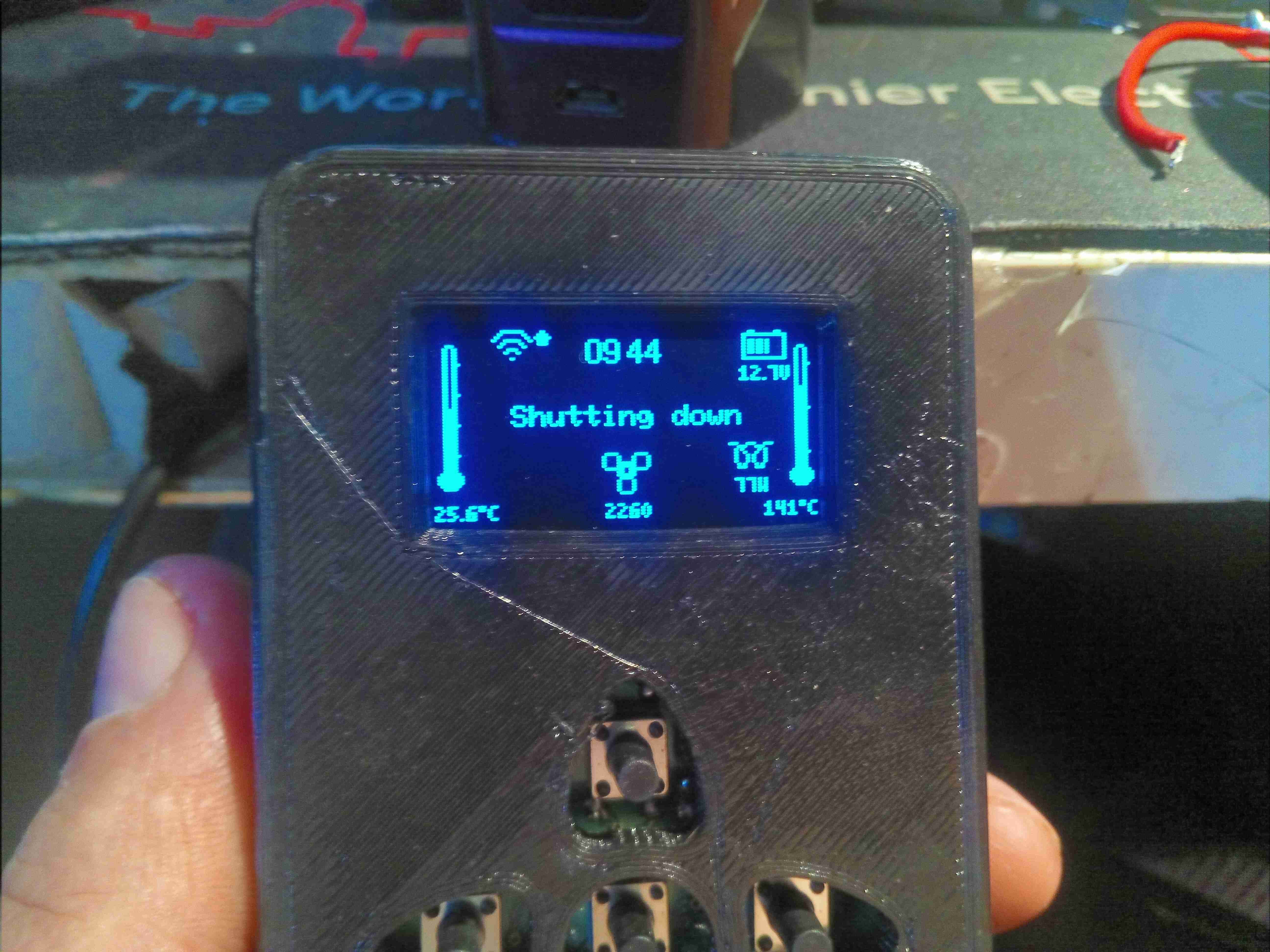
Shutdown
When a shutdown is initiated, the heater brings the glow plug back on & reduces the fuelling rate to minimum for a couple of minutes, before stopping fuel flow. The glow plug remains running for a while to burn off any remaining fuel residue.
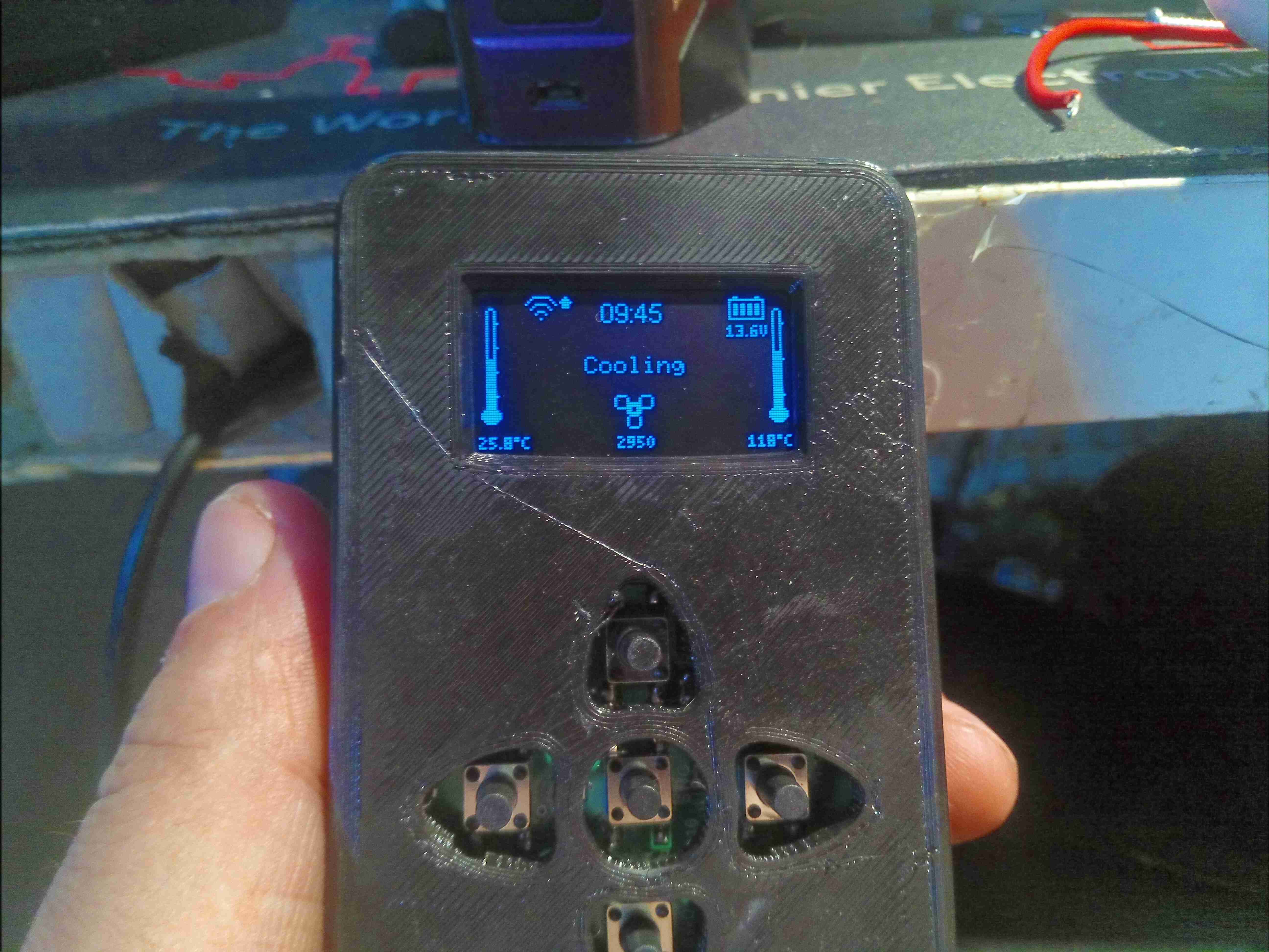
Cooling Cycle
Finally, the ECU cuts power to the glow plug, and keeps the fan running at medium speed until the heat exchanger cools to below 55°C.
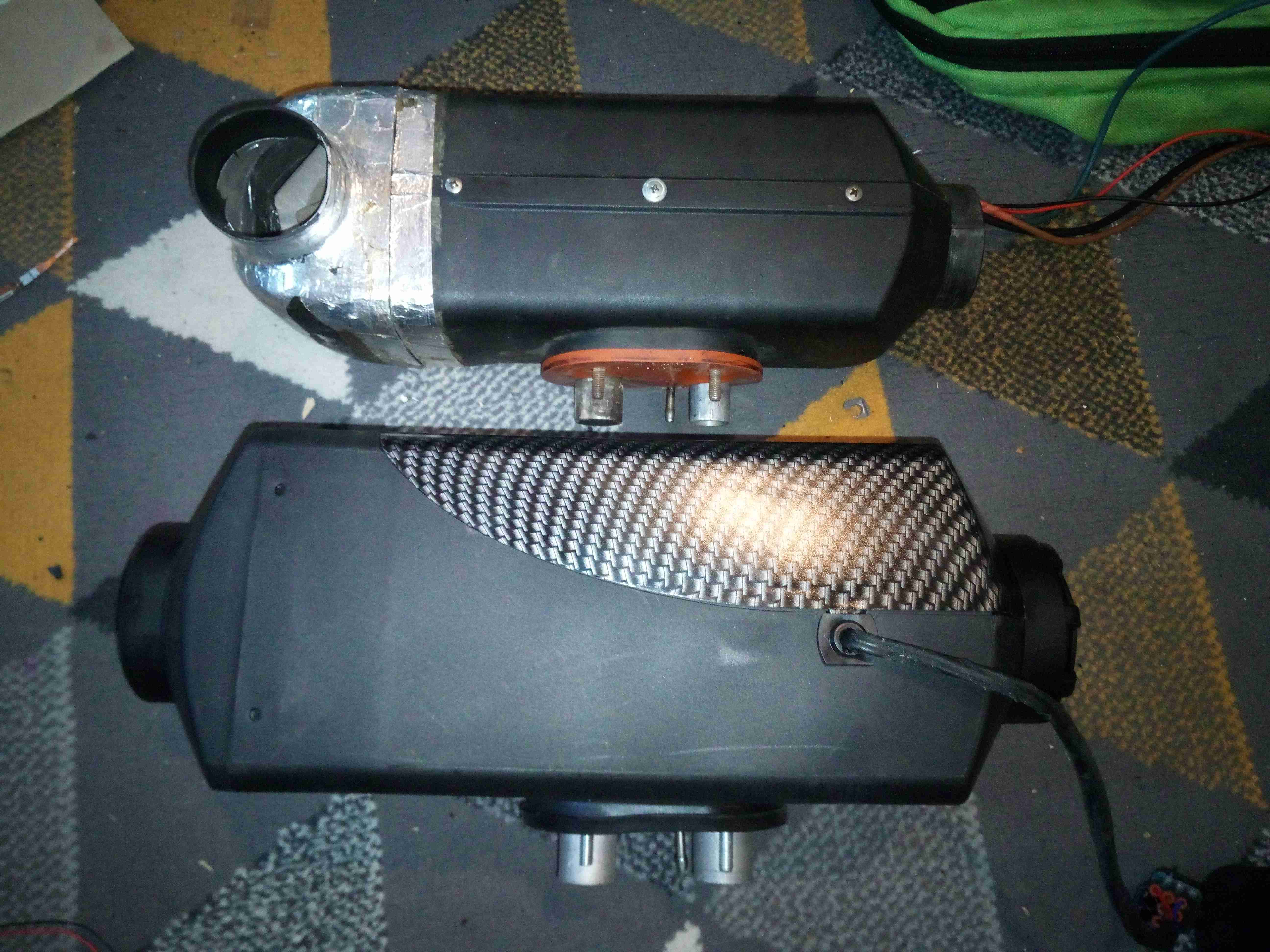
As part of the giant power bank that gets dragged to all my major camping trips & festivals, there is an old Eberspacher Diesel heater, a D1LCC from at first guess somewhere in the mid 90’s. At only 1.8kW heat output this is a little small for our current tent, and it struggles to keep the temperature comfortable at night, so with Chinese clones on the market these days much cheaper than the Eberspacher or Webasto units, a replacement was up! Still, the old Eberspacher is in working order, and will probably get used for some other project.
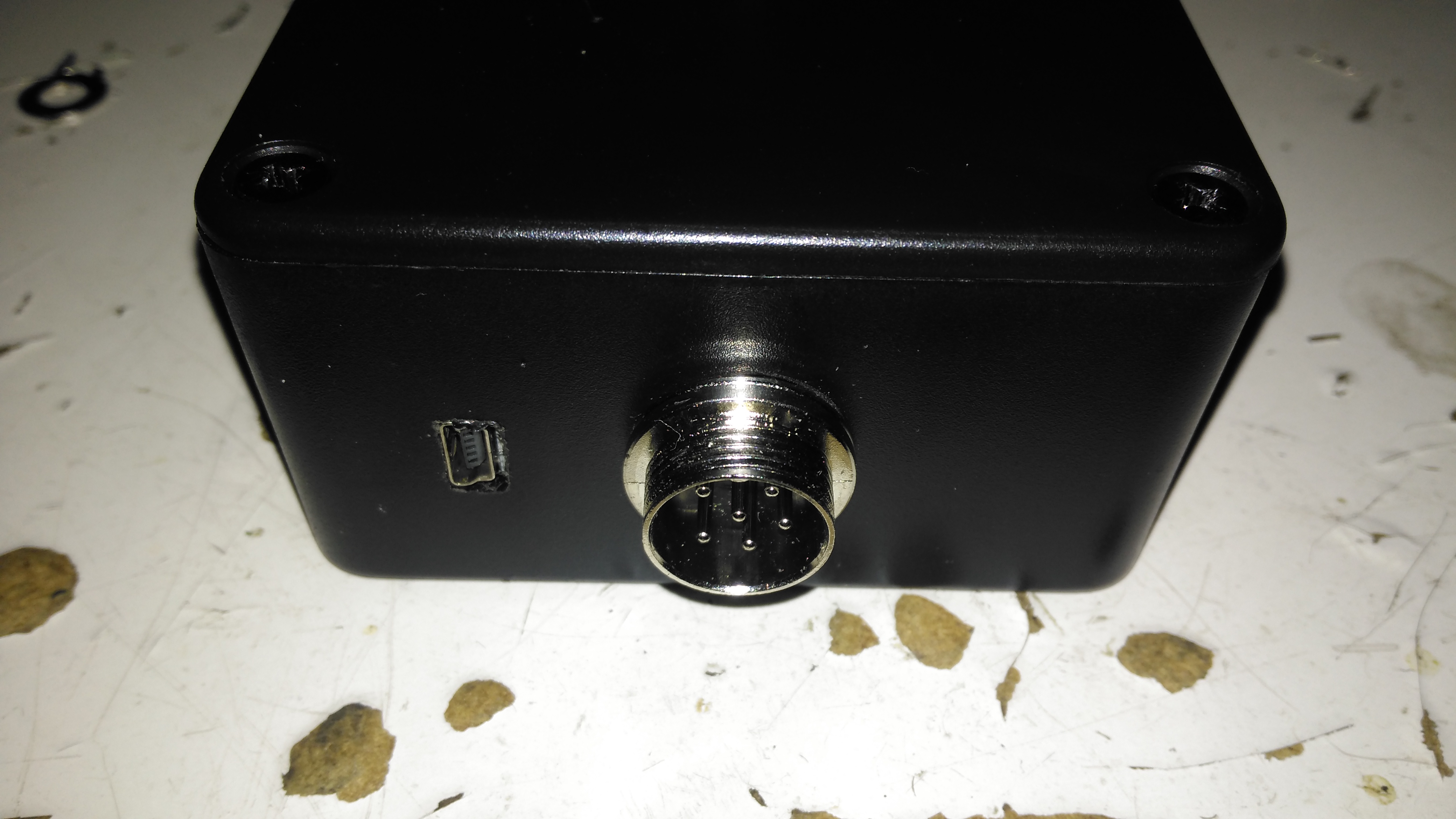
Diesel Heaters
After removing the old D1LCC & placing it next to the new one, the size difference is obvious! The new heater is a Chinese clone of the Eberspacher D4 unit, allegedly uprated to 8kW. (In reality, it’s probably around 5kW heat output at full tilt). Luckily, it’s not that much larger than the old one, so it’ll go into the same space.
New Heater
The port layout on the bottom of the heater is identical apart from intake port size, a quick attack of the baseplate with a grinder to remove the old hole pattern allowed the supplied mounting plate to fit correctly into place for the new heater. The duct size on this unit is also bigger than the old 60mm – 75mm duct is used on these large units. No modification to the vent hole was required, as the 75mm vent already fit perfectly. To clear the fittings on the top of the fuel tank, which is just underneath the hot air exhaust cowling of the heater, the mounting plate is fixed using 10mm nylon standoffs, this also helps get a bit more natural airflow around the base of the heater, as the mounting gets to 90°C in operation at full power!
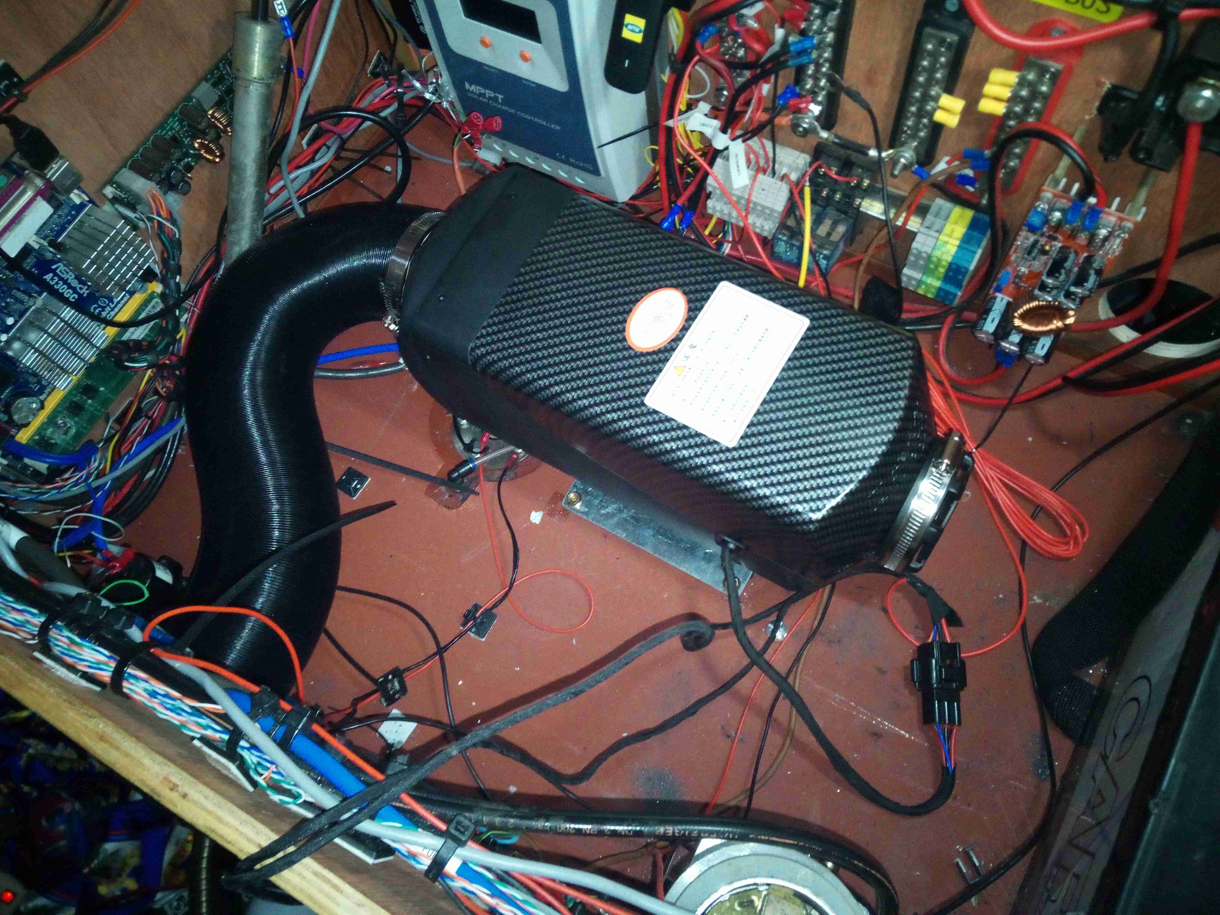
These heaters don’t use the Eberspacher standard switch wire for control – there are only 3 pins in the loom to the controller, for 5v power & an odd UART which uses gated TX/RX to avoid having a separate line for each.
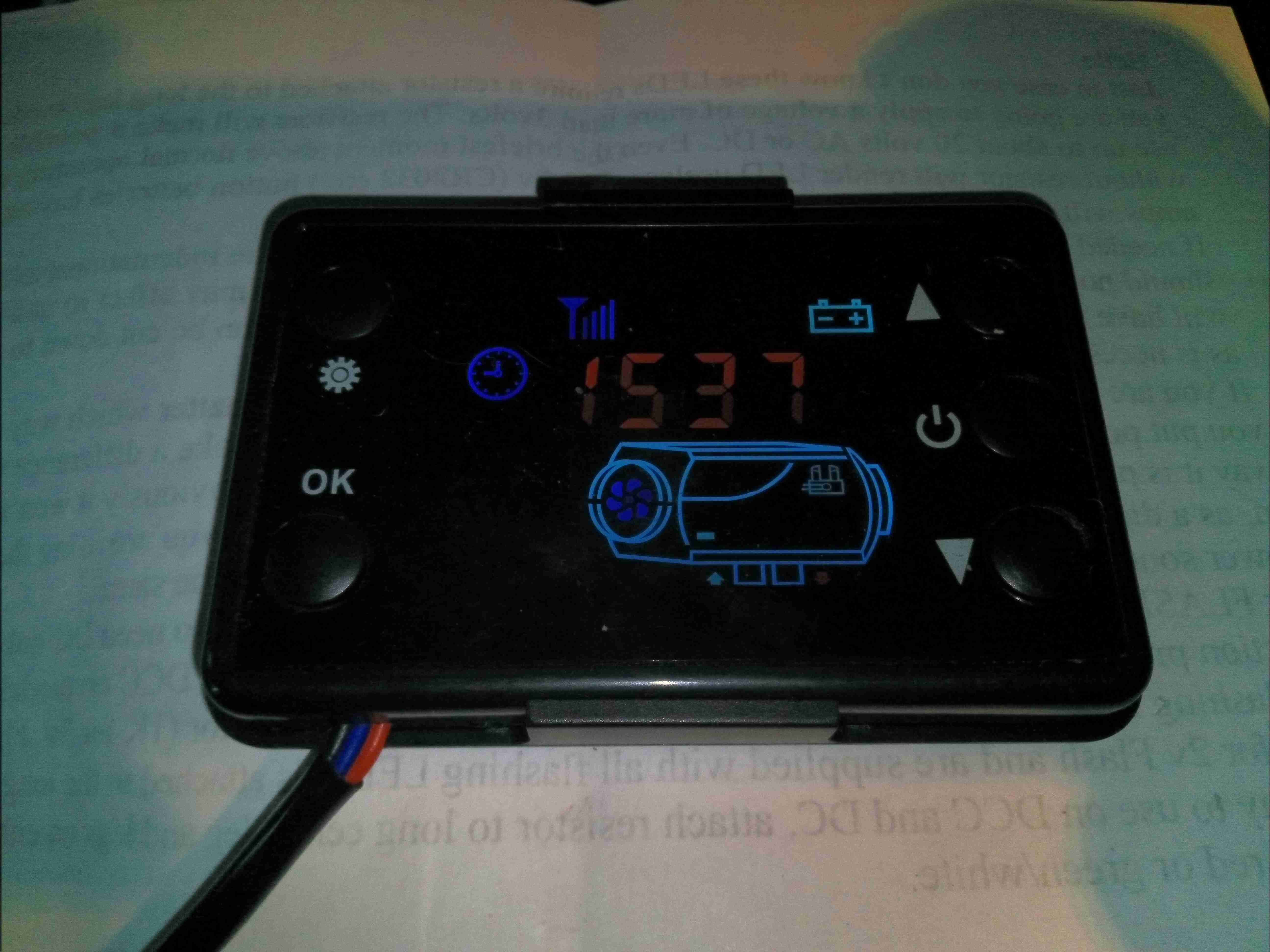
Stock Controller
The stock controller has quite a nice looking LCD display, but it’s less than responsive & the backlight is always on at full tilt. It’s also much larger than the Eberspacher 701 controller so would require some rejigging of the control panel on the trolley. The built-in thermostat is also inaccurate, being almost 5°C high no matter what the room temperature. Ray Jones from Down Under has designed an open source ESP32 based controller for these heaters, and one of these is currently being built to control the unit. More to come on this bit!
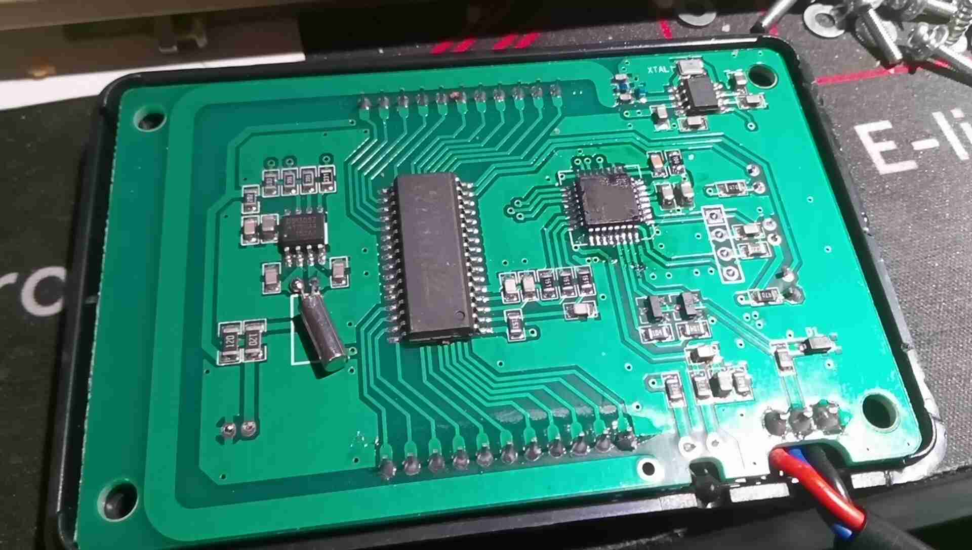
Stock Controller PCB
A quick teardown of the controller reveals pretty simple internals, there’s a microcontroller, probably an STM8 device by looking at the programming header, but the markings have been scrubbed off the IC. There’s a standard LCD controller IC, a RTC which isn’t battery backed, and a 433MHz receiver IC with PCB trace antenna.
I wasn’t able to get the remote control function working with any of the remotes I have, any attempt at pairing a remote didn’t give any response from the controller unit. I also tried a 315MHz remote, but that didn’t work either. Not an issue since I’m building a much better open source controller.
Fuel & Exhaust
Under the base is the exhaust system & the fuel dosing pump. There’s a small filter in the feed line from the tank to keep crap out of the pump, and nylon fuel line then runs the fuel to the heater inlet. The exhaust is made as gas-tight as possible with foil tape & exhaust paste, to keep the exhaust fumes contained in the pipework until they’re vented outside. The rest of the exhaust after the right hand silencer is done in brazed 22mm copper pipe, and a piece of Eberspacher exhaust duct is removable from the final exhaust tail for storage. The black pipe is the combustion air intake, which is simply fed into a silencer cable tied to the trolley frame.
Heater Ports
The 3 ports are visible under the mounting plate, the square hole cut out of the trolley base to accommodate everything.
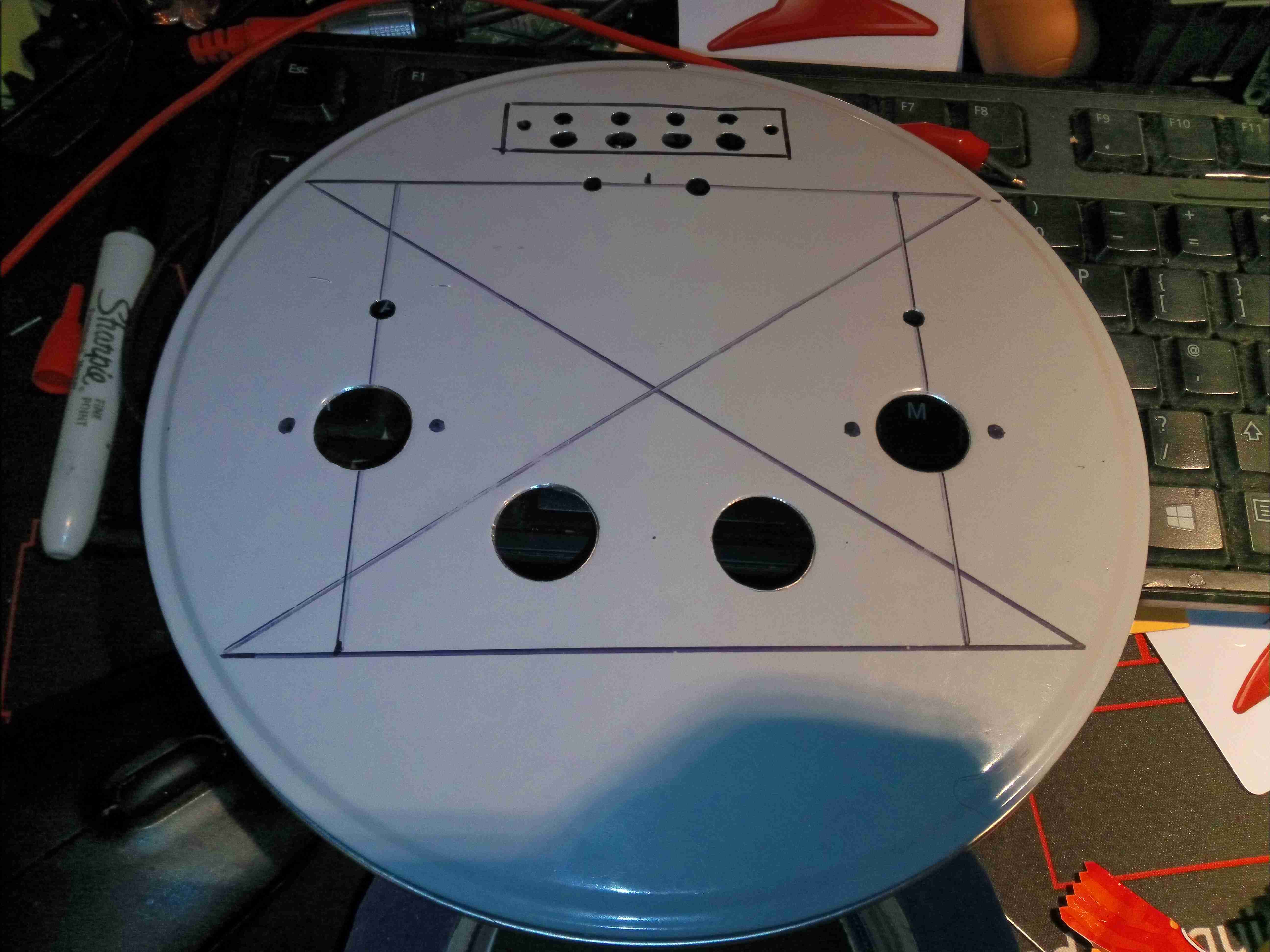
I figured it was about time I built another valve amplifier, and since I already had most of the required parts in stock, here it is! Above is the lid of a cake tin sourced from a local shop as a case, marked out & drilled for the valve sockets, output transformers & speaker terminals.
The ECL82 valve is a Triode & Audio Output Pentode in a single envelope, requiring only a single valve per audio channel. There are a pair of extra holes drilled here for a couple of EM80 magic-eye valves wired as VU meters to give a bit of a lightshow.
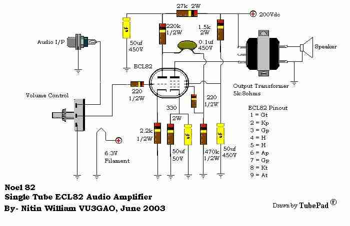
Amplifier Schematic
Here’s the base schematic for the Class-A ECL82 amplifier sections, obtained from the interweb. It’s pretty basic, and doesn’t mention a value for the volume potentiometer, so I used a 100K audio taper for that. Power will be supplied from low-voltage DC, running through a high voltage DC-DC converter for the anode supply of 200v, and a 5A buck converter for the 6.3v filament supply.
EM80 Schematic
The EM80 side is as the schematic above, the signal input being taken directly from the Pentode anode of the ECL82. I have removed the second 1N4148 diode down to ground, leaving only a single diode.
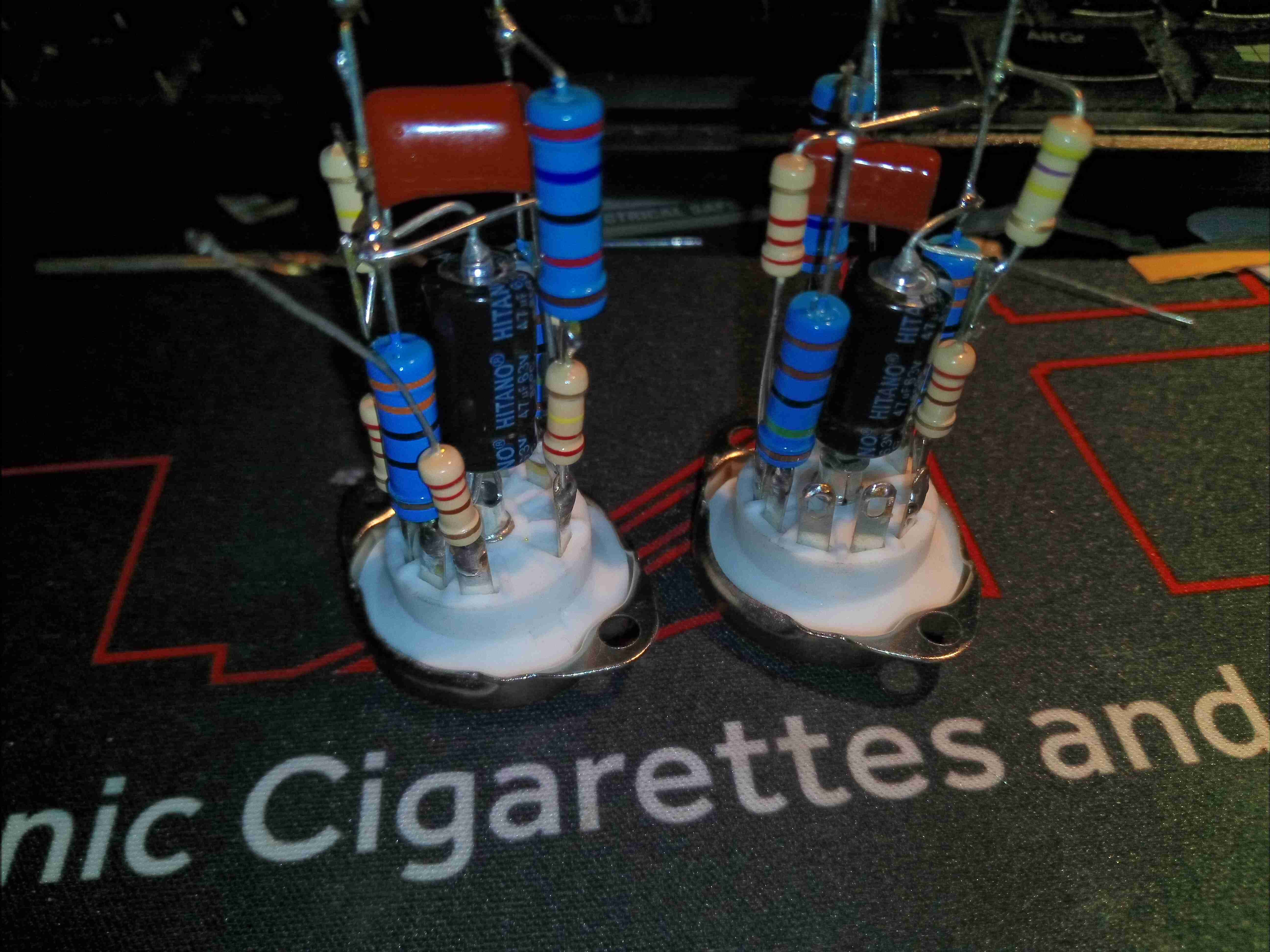
Valve Base
Most of the parts comprising the ECL82 amplifier stages are mounted directly on the back of the valve sockets, requiring only a 6.3v filament supply, 200v anode supply & audio I/O connections. Axial electrolytics have been used for ease of assembly, even though they’re getting a little expensive nowadays!
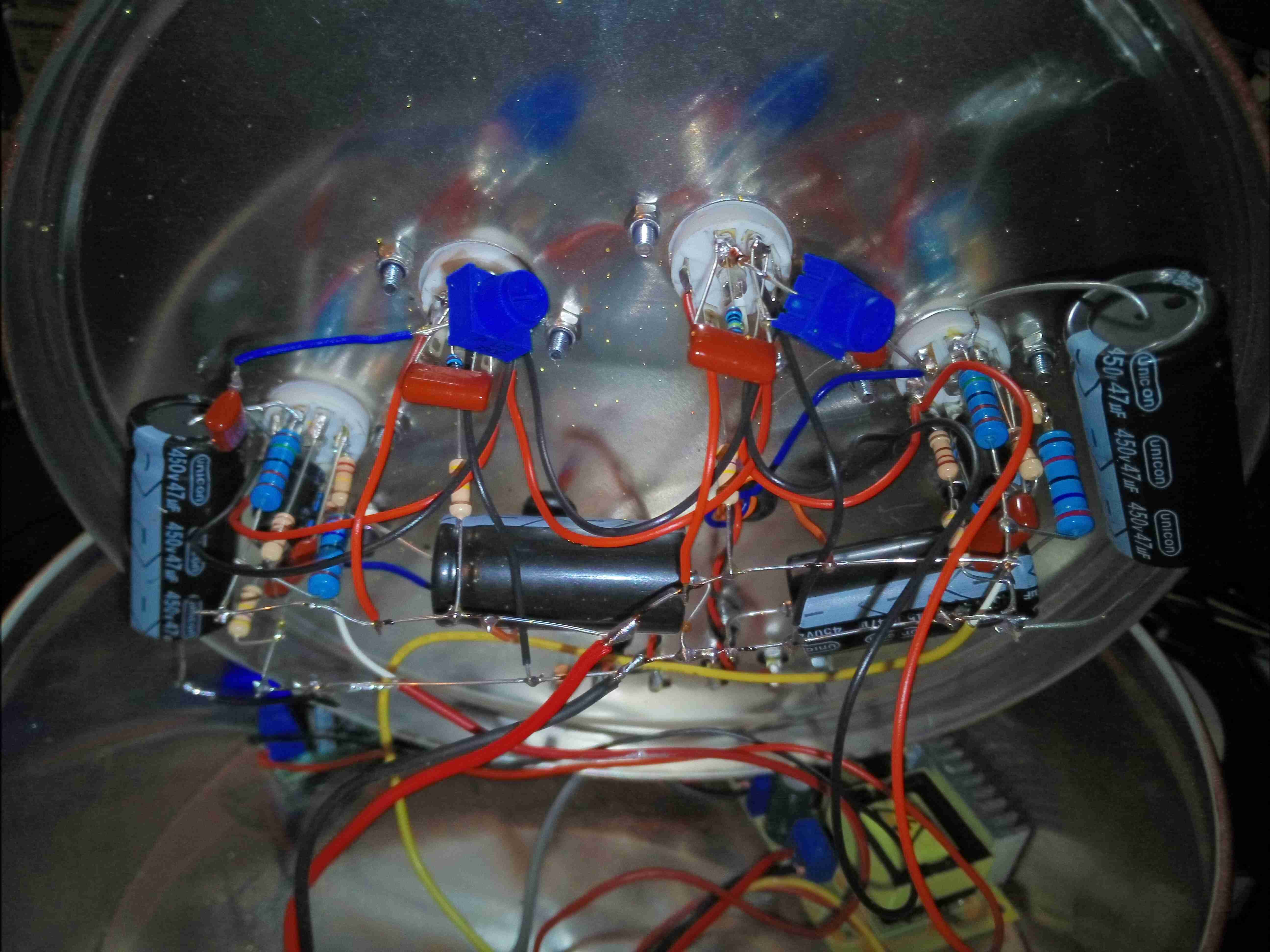
Point To Point Wiring
After fitting the components to the top lid, point-to-point wiring is used to connect up the valve socket assemblies. Some large electrolytics provide B+ smoothing, and all the filaments are daisy-chained in parallel. Audio is brought in on micro-coax from the I/O, and straight out to the output transformers on twisted pairs, keeping the audio wiring away from the B+ voltage.
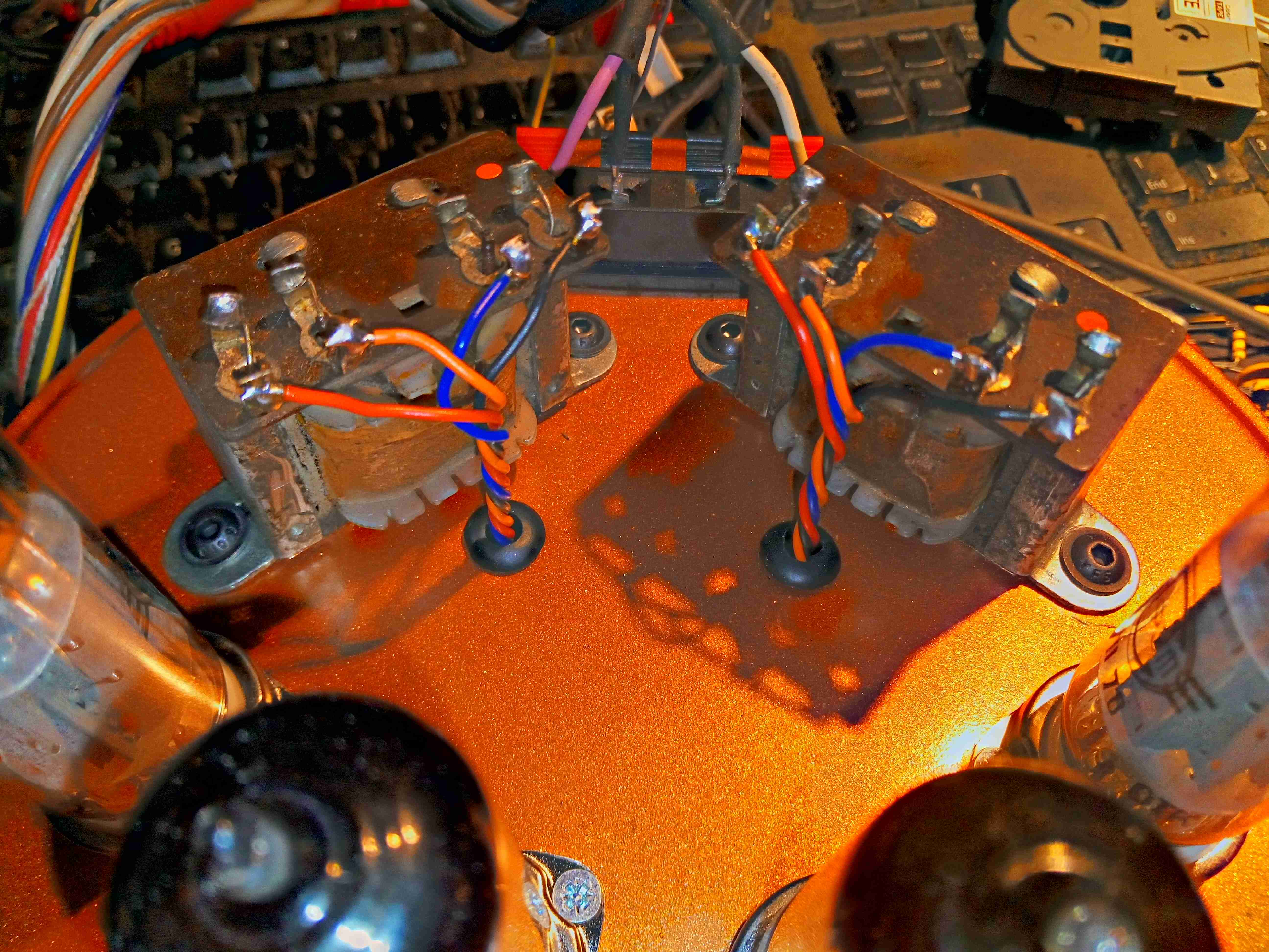
Output Transformers
The audio transformers, from a 1960’s Philips Radiogram, are mounted behind the valves, with the wiring emerging through holes in the case. I’ve already done the paint job here, in metallic copper.
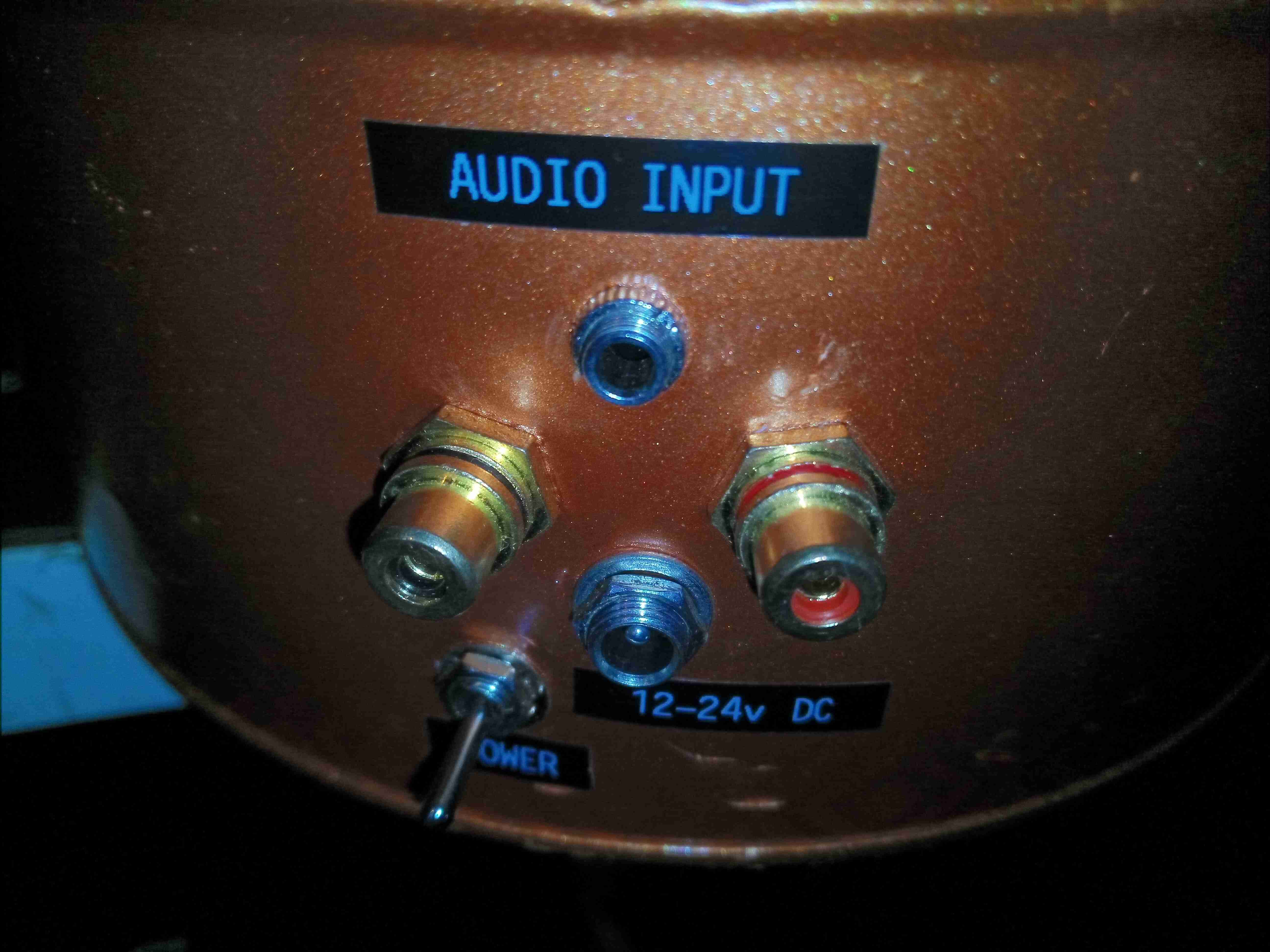
I/O
Audio & power sockets are on the back of the tin, with both 3.5mm Stereo inputs & phono inputs. A DC barrel jack takes care of the power, accepting 12-24v.
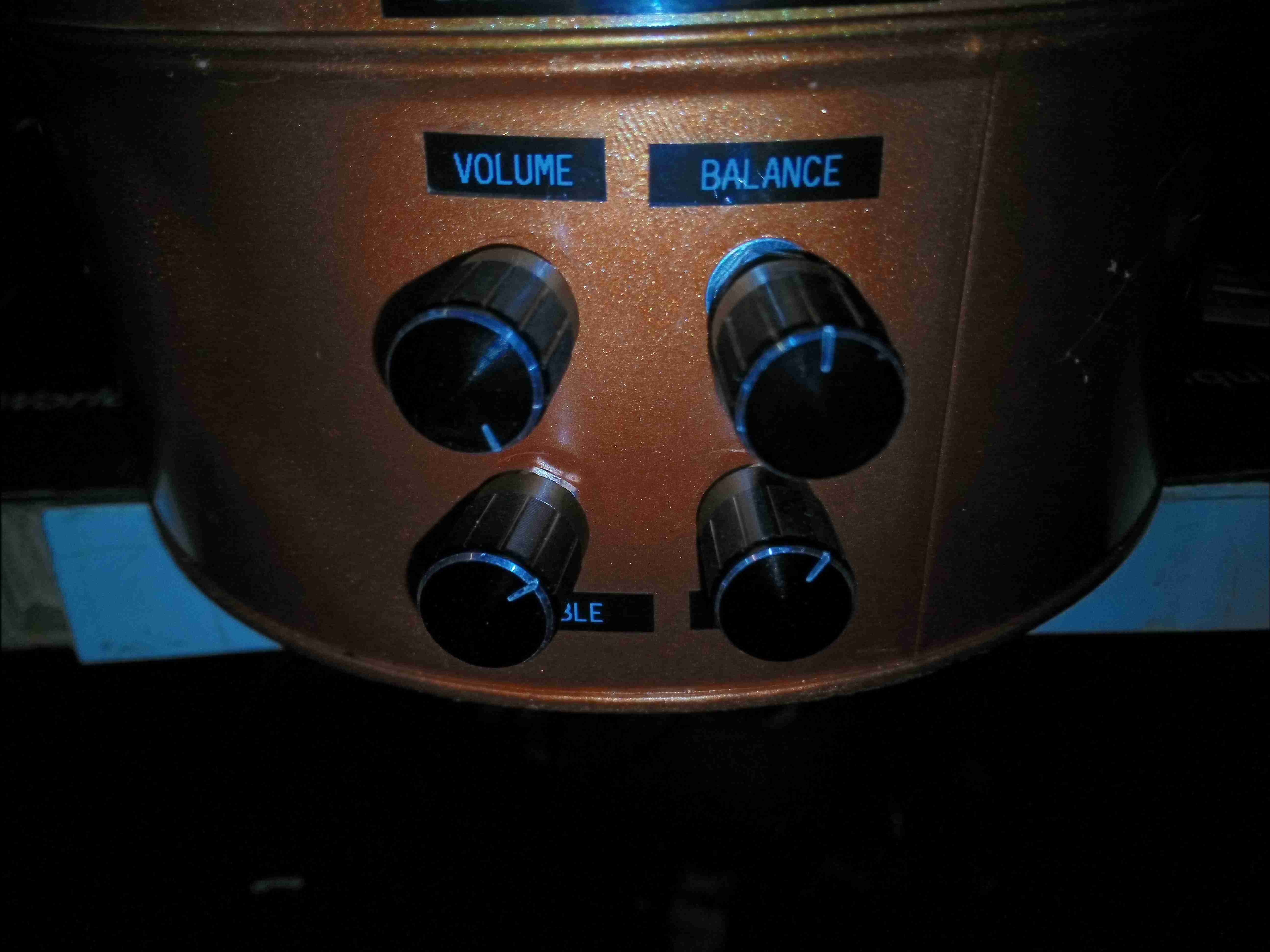
Controls
Controls on the front provide volume, balance, bass & treble adjustments.
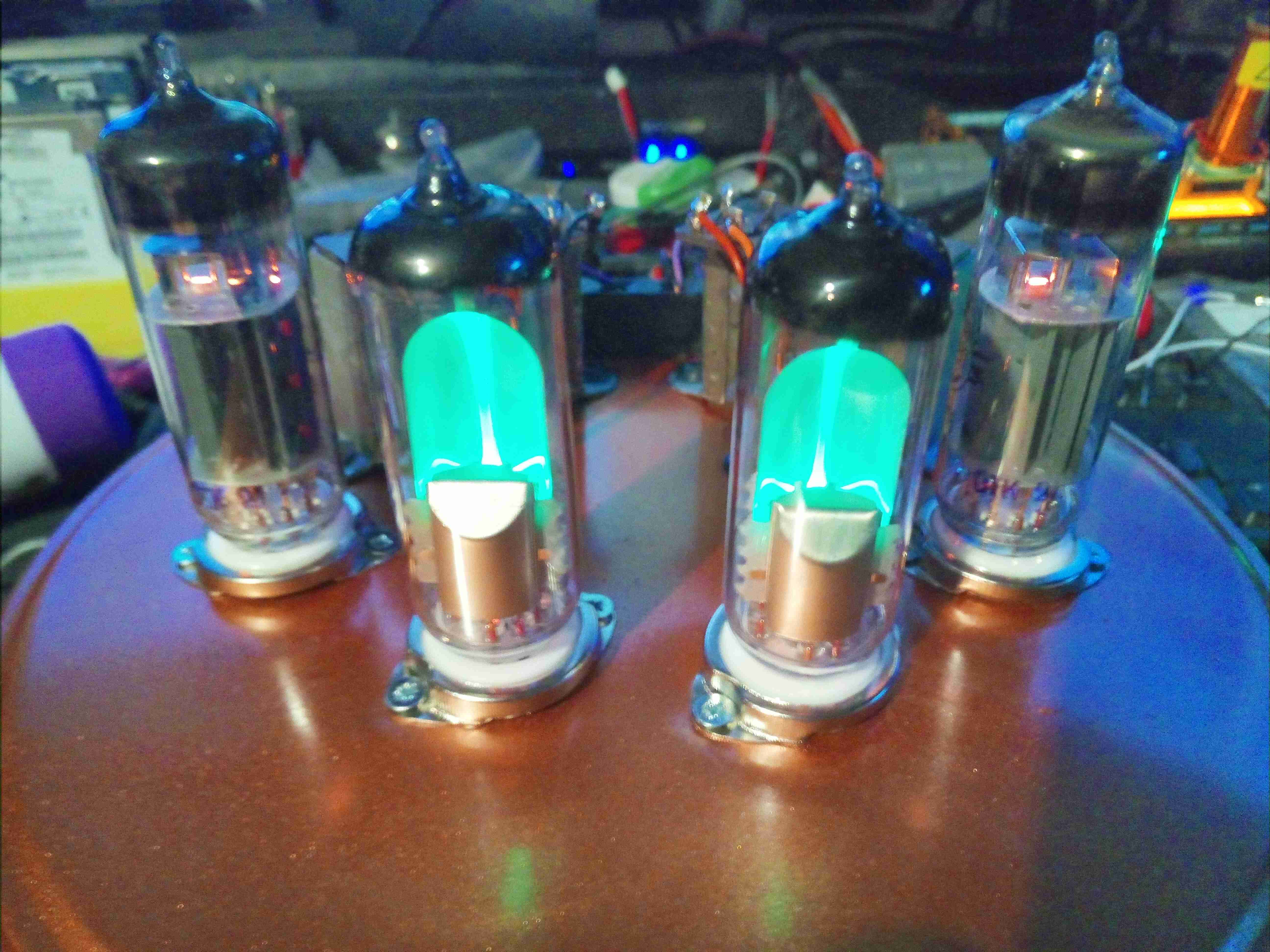
Amplifier Operational
Here’s the amplifier with it’s valves glowing nicely. Total power consumption is roughly 30W, using NOS Svetlana ECL82s & EM80s. In operation there is no hum or noise in the background, with no audio input the connected speakers are entirely silent.
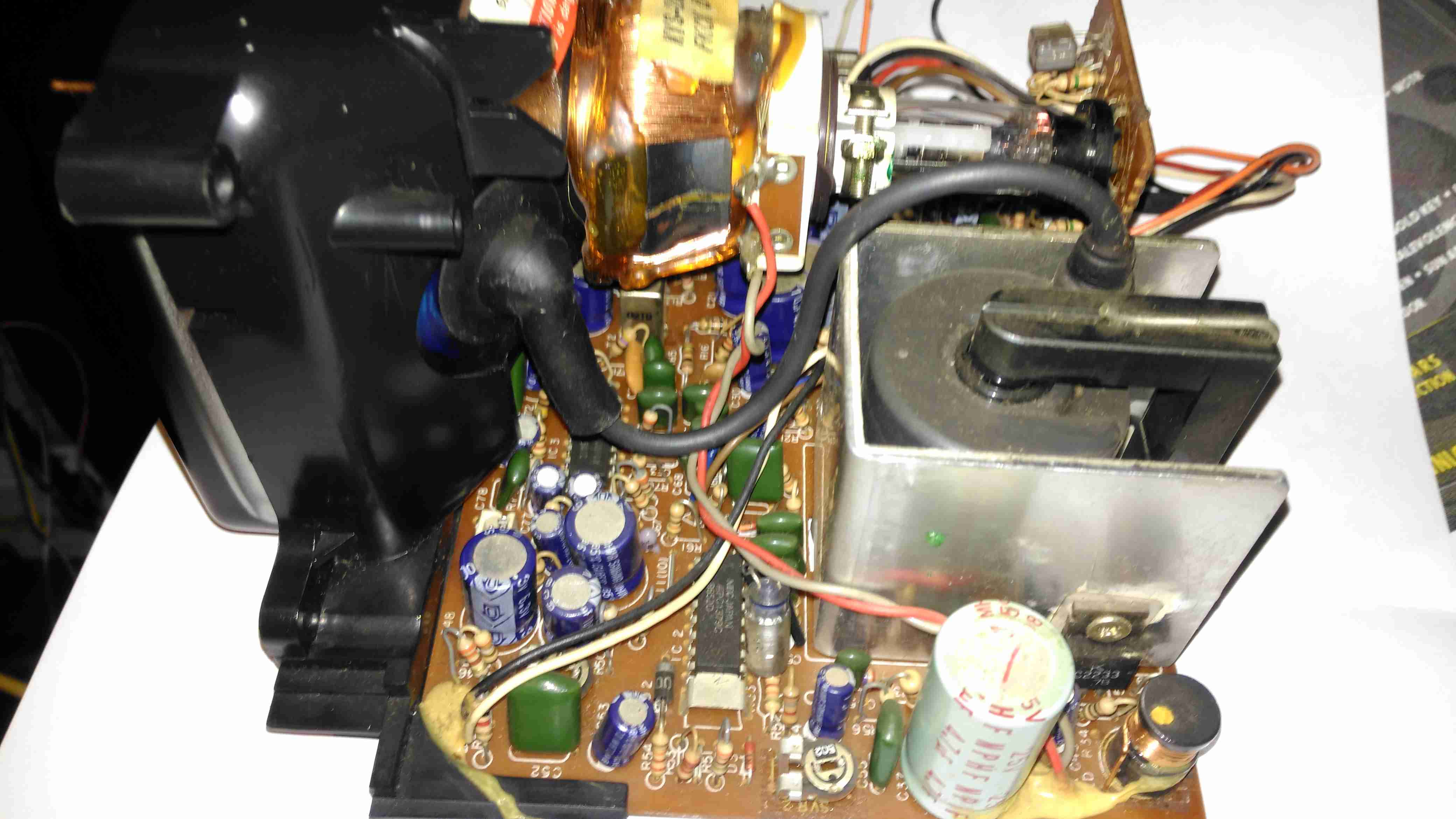
Here’s the CRT & it’s drive board removed from the main chassis. Nicely modular this unit, all the individual modules (radio, tape, TV), are separate. This is effectively a TV itself, all the tuner & IF section are onboard, unlike in other vintage units I’ve modified, where the tuner & IF has been on a separate board. There’s a 3-pin header bottom centre for the tuning potentiometer, and external antenna input jack. The internal coax for the built in antenna has been desoldered from the board here. here a the usual controls on the back for adjusting brightness, contrast & V Hold, all the other adjustments are trimmers on the PCB.
Unfortunately after 30+ years of storage, this didn’t work on first power up, neither of the oscillators for vertical or horizontal deflection would lock onto the incoming signal, but a couple of hours running seemed to improve things greatly. The numerous electrolytic capacitors in this unit were probably in need of some reforming after all this time, although out of all of them, only 21 are anything to do with the CRT itself.
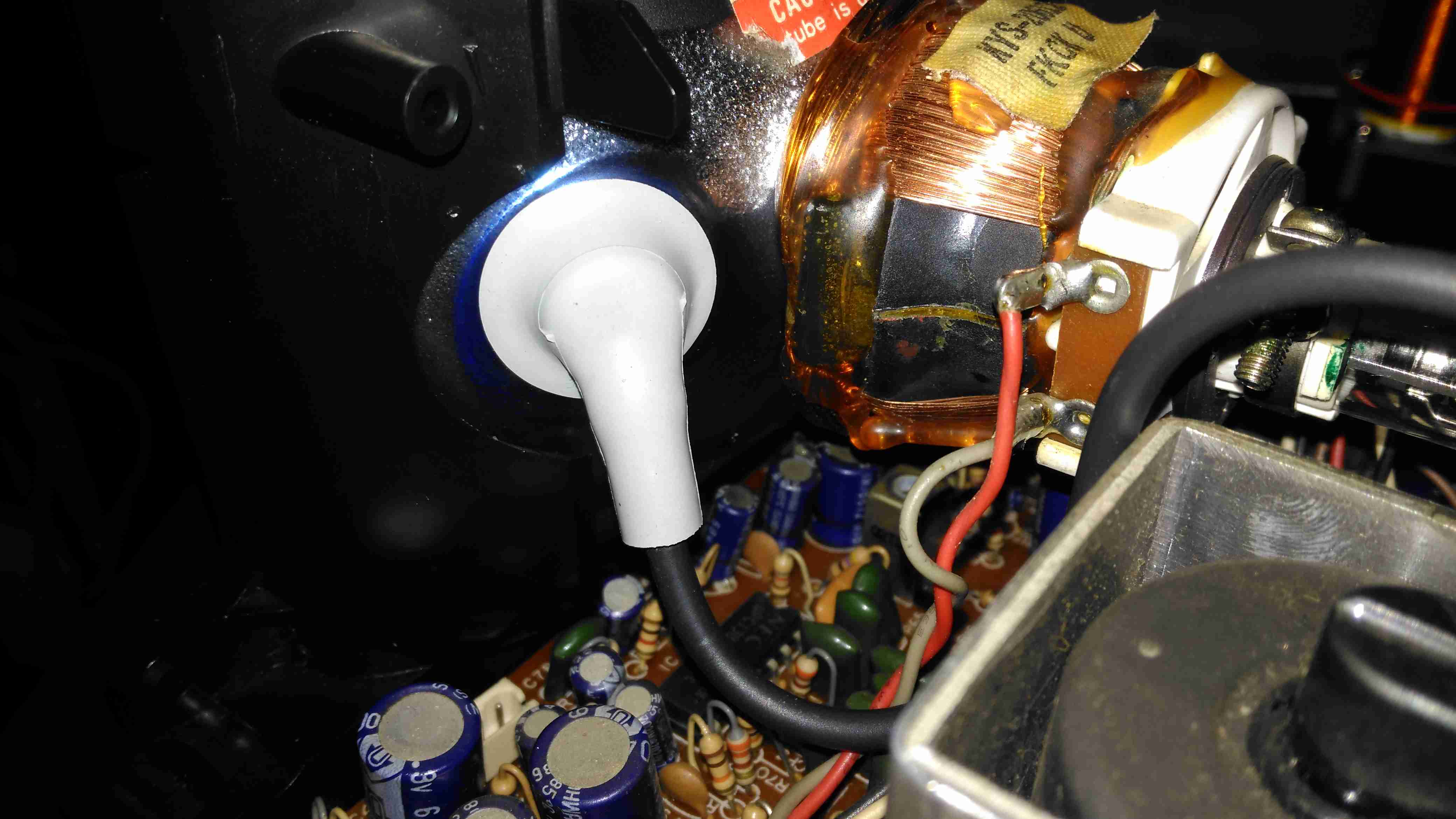
Anode Cap
Here’s the anode side of the unit, with the small flyback transformer. The rubber anode cap has become very hard with age, so I’ll replace this with a decent silicone one from another dead TV. The Horizontal Output Transistor (a 2SC2233 NPN type) & linearity coil are visible at the bottom right corner of the board. Unfortunately, the disgusting yellow glue has been used to secure some of the wiring & large electrolytics, this stuff tends to turn brown with age & become conductive, so it has to be removed. Doing this is a bit of a pain though. It’s still a little bit flexible in places, and rock hard in others. Soaking in acetone softens it up a little & makes it easier to detach from the components.
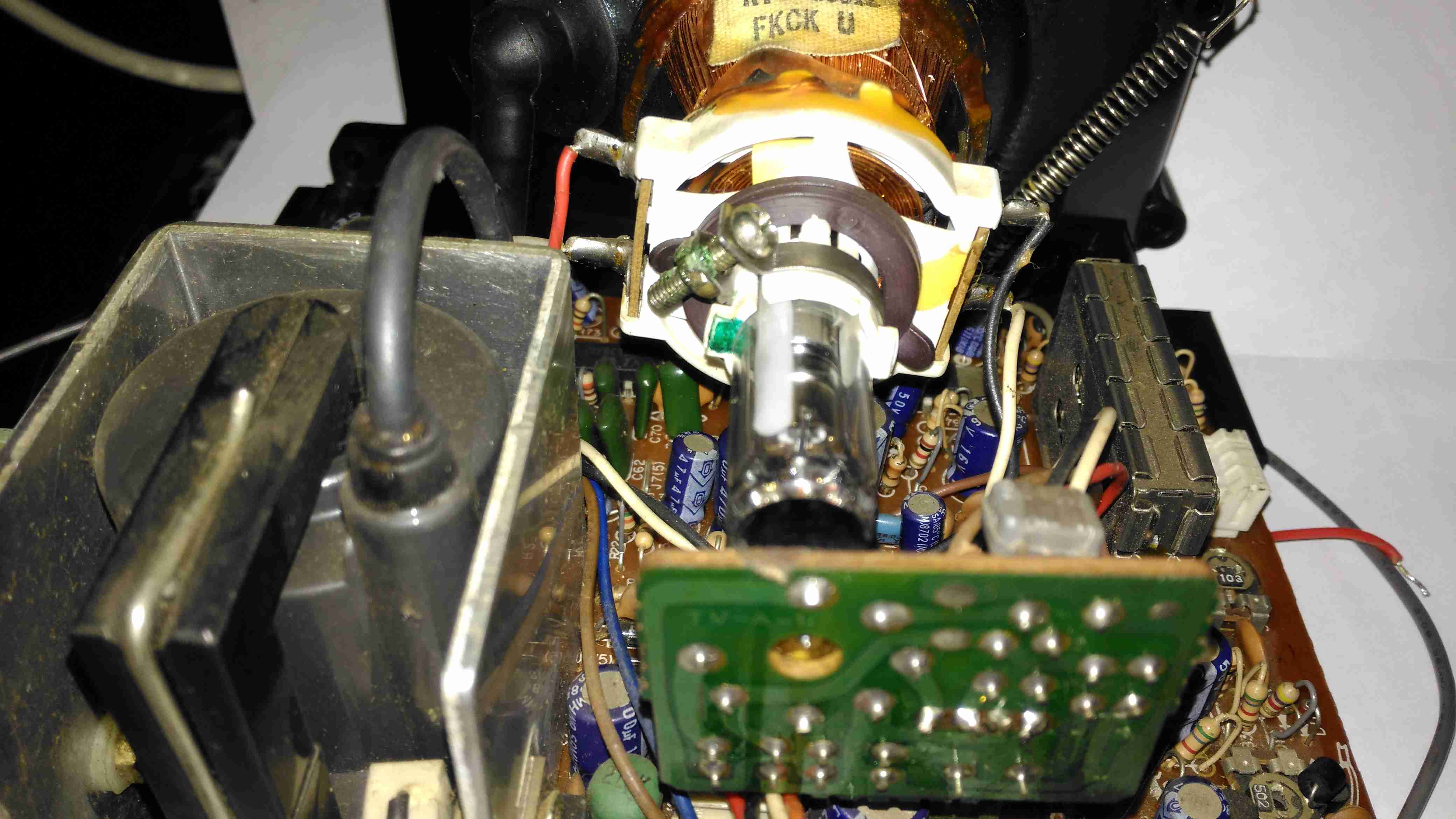
Neck PCB
There’s little on the neck board apart from a few resistors, forming the limiting components for the video signal, and the focus divider of 1MΩ & 470KΩ feeding G3. No adjustable focus on this unit. There’s also a spark gap between the cathode line & ground, to limit the filament to cathode voltage. The flyback transformer is nestled into the heatsink used by the horizontal output transistor & a voltage regulator transistor.
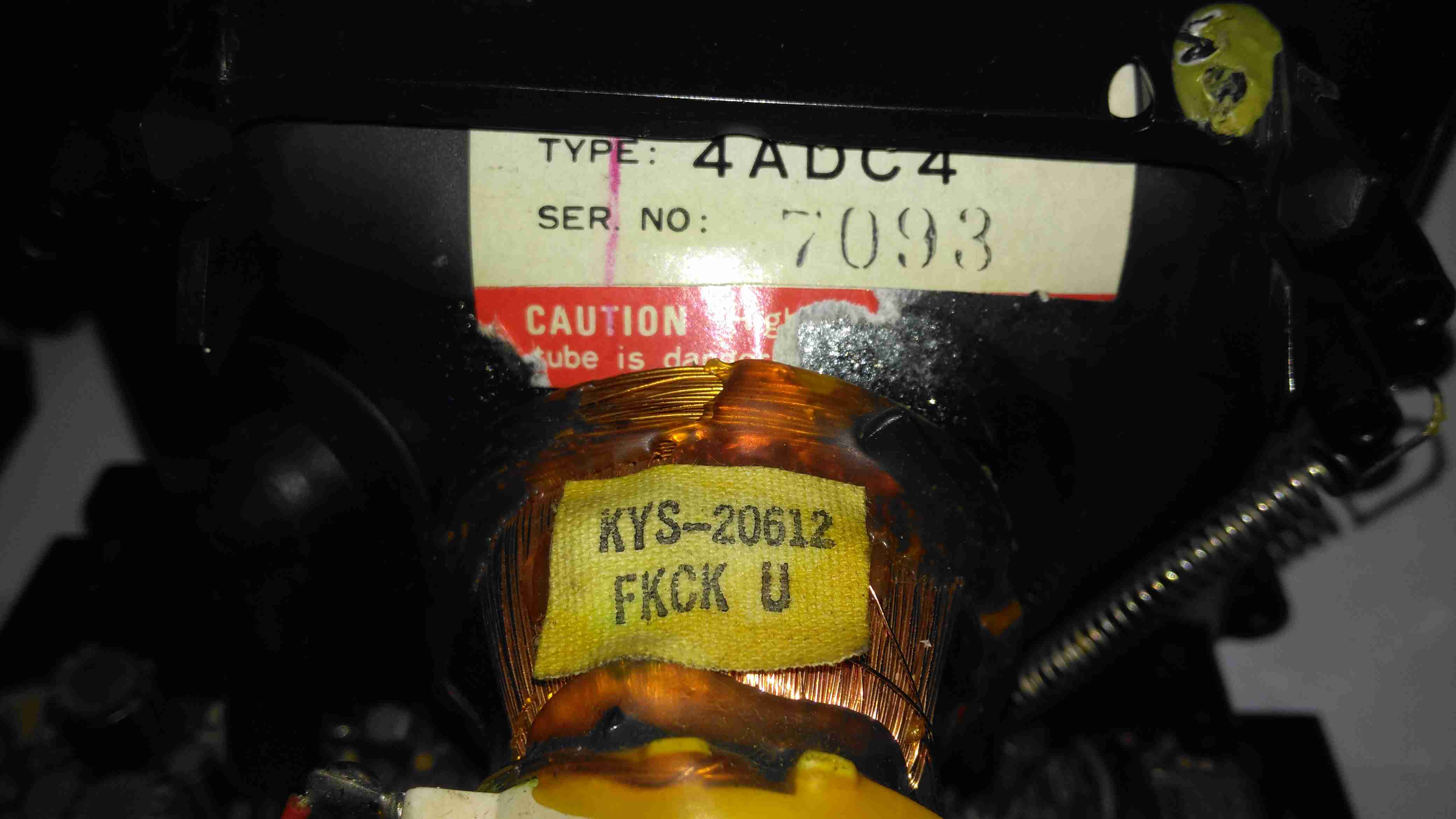
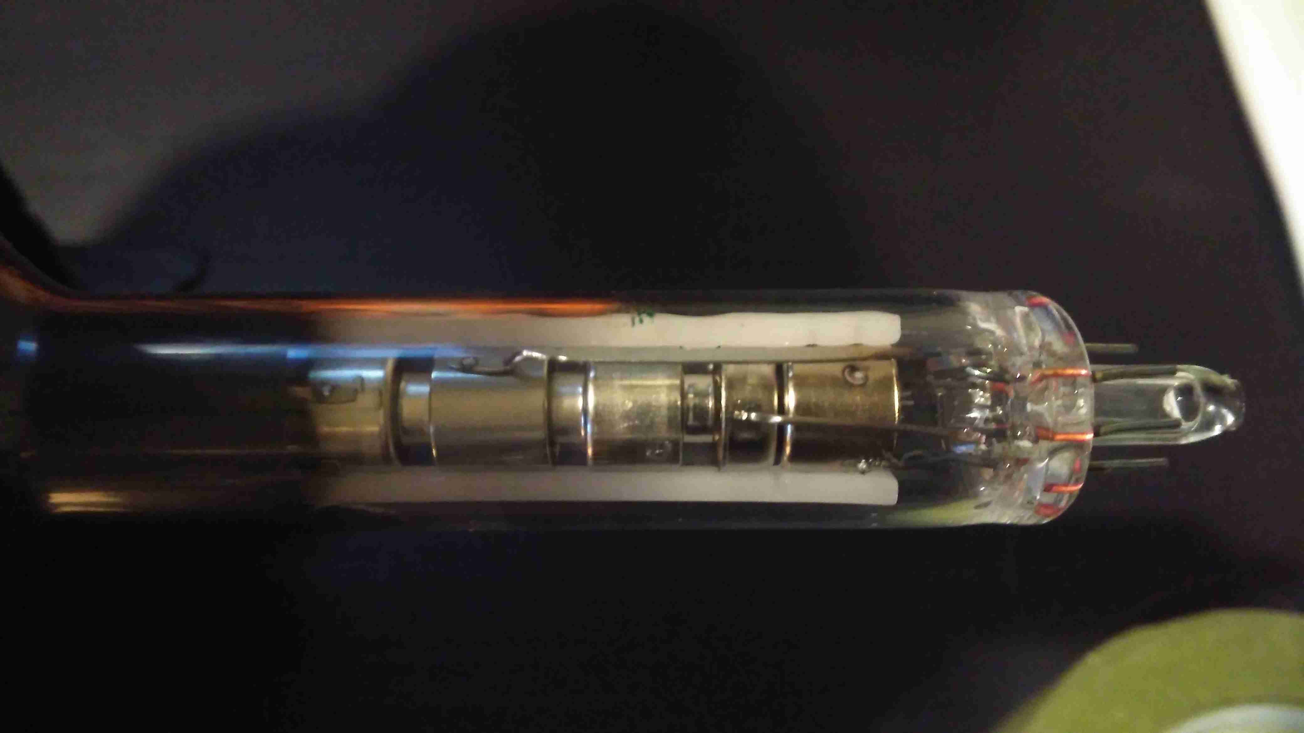
Tube Details
The CRT is a Samsung Electron Devices 4ADC4, with a really wide deflection angle. It’s a fair bit shorter than the Chinese CRT I have which is just a little larger, with a neck tube very thin indeed for the overall tube size.
Unusually, while the filament voltage is derived from the flyback transformer as usual, it’s rectified into DC in this unit, passing through a 1Ω resistor before the filament connection. I measured 5.3v here. The glow from the filament is barely visible even in the dark.
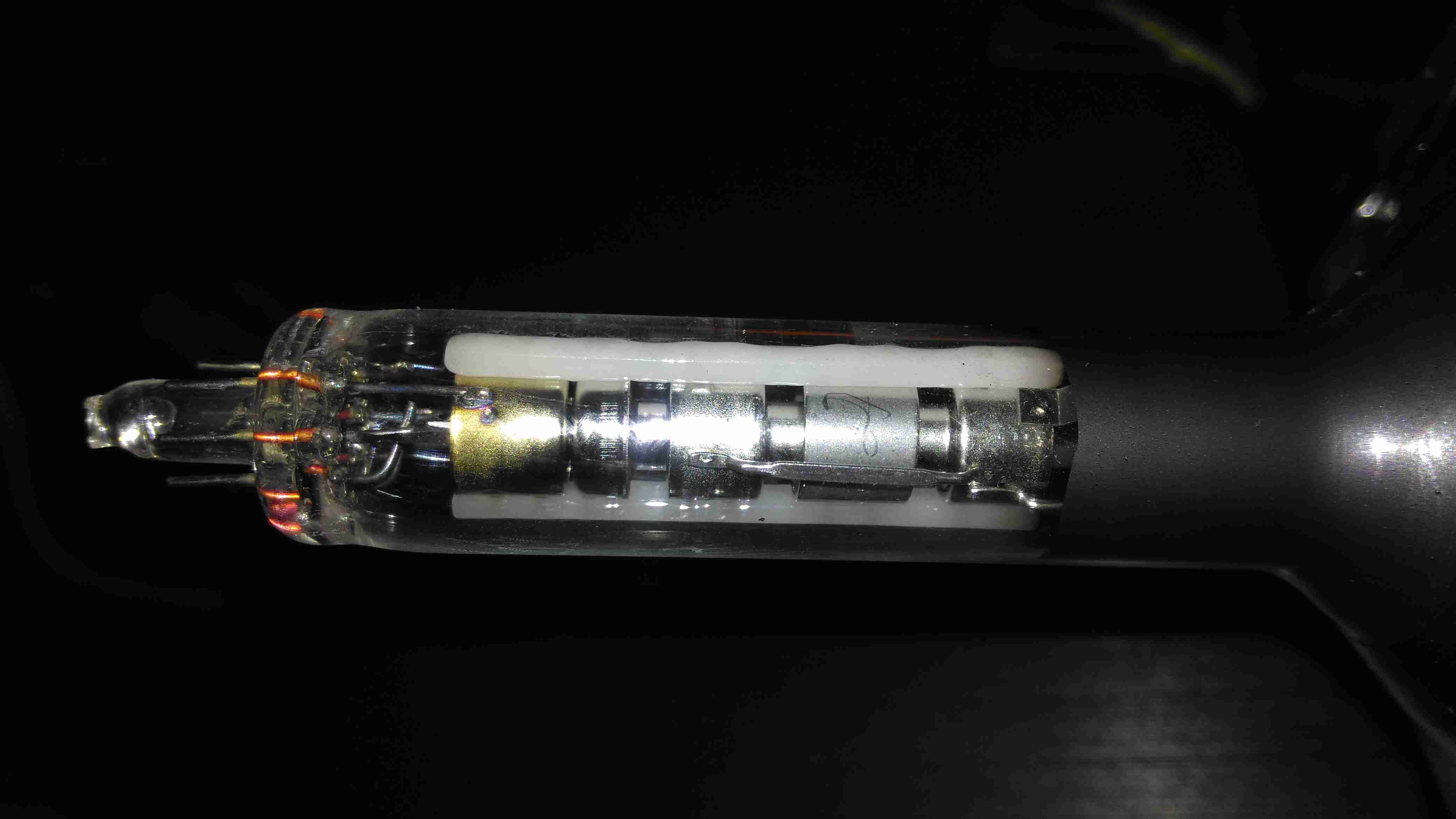
Electron Gun 1
The electron gun is the usual for a monochrome tube, with 7 pins on the seal end.
Electron Gun 2
The electrodes here from left are Final Anode, G3 (Focus Grid), Accelerating Anode, G2 (Screen Grid), G1 (Control Grid). The cathode & filament are hidden inside G1. In operation there’s about 250v on G2, and about 80v on G3.
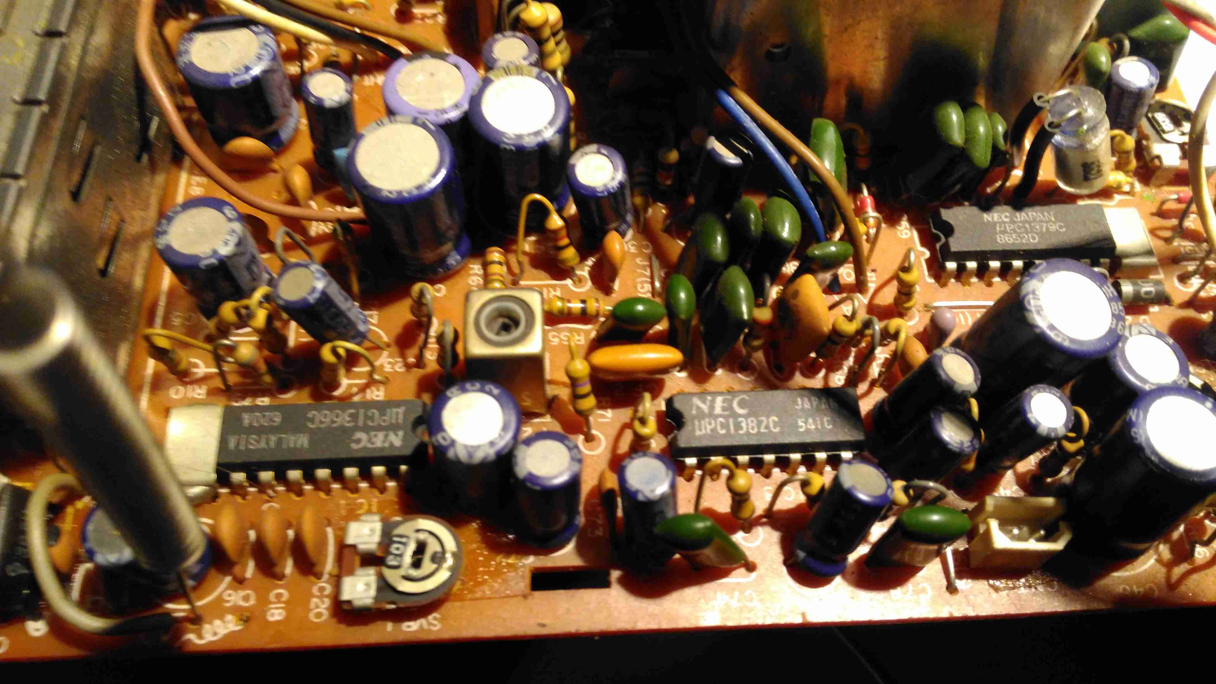
Chipset
The chipset used here is all NEC, starting with a µPC1366C Video IF Processor, which receives the IF signal from the tuner module to the left. This IC outputs the standard composite signal, and a modulated sound signal.
This then splits off to a µPC1382C Sound IF Processor & Attenuator IC, which feeds the resulting sound through the two pin header at the right bottom edge of the board to the audio amplifier in the chassis.
The composite video signal is fed through a discrete video amplifier with a single 2SC2229 transistor before going to the CRT cathode.
The remaining IC is a µPC1379C Sync Signal Processor, containing the sync separator, this is generating the required waveforms to drive the CRT deflection systems from another tap off the composite video line.
From this chip I can assume the unit was built around 1986, since this is the only date code on any of the semiconductors. Besides these 3 ICs, the rest of the circuit is all discrete components, which are well-crammed into the small board space.
There are 5 trimmer potentiometers on the board here, I’ve managed to work out the functions of nearly all of them:
SVR1: IF Gain Adjust
SVR2: H. Hold
SVR3: V. Size
SVR4: B+ Voltage Adjust
SVR5: Tuner Frequency Alignment? It’s in series with the tuning potentiometer in the chassis.
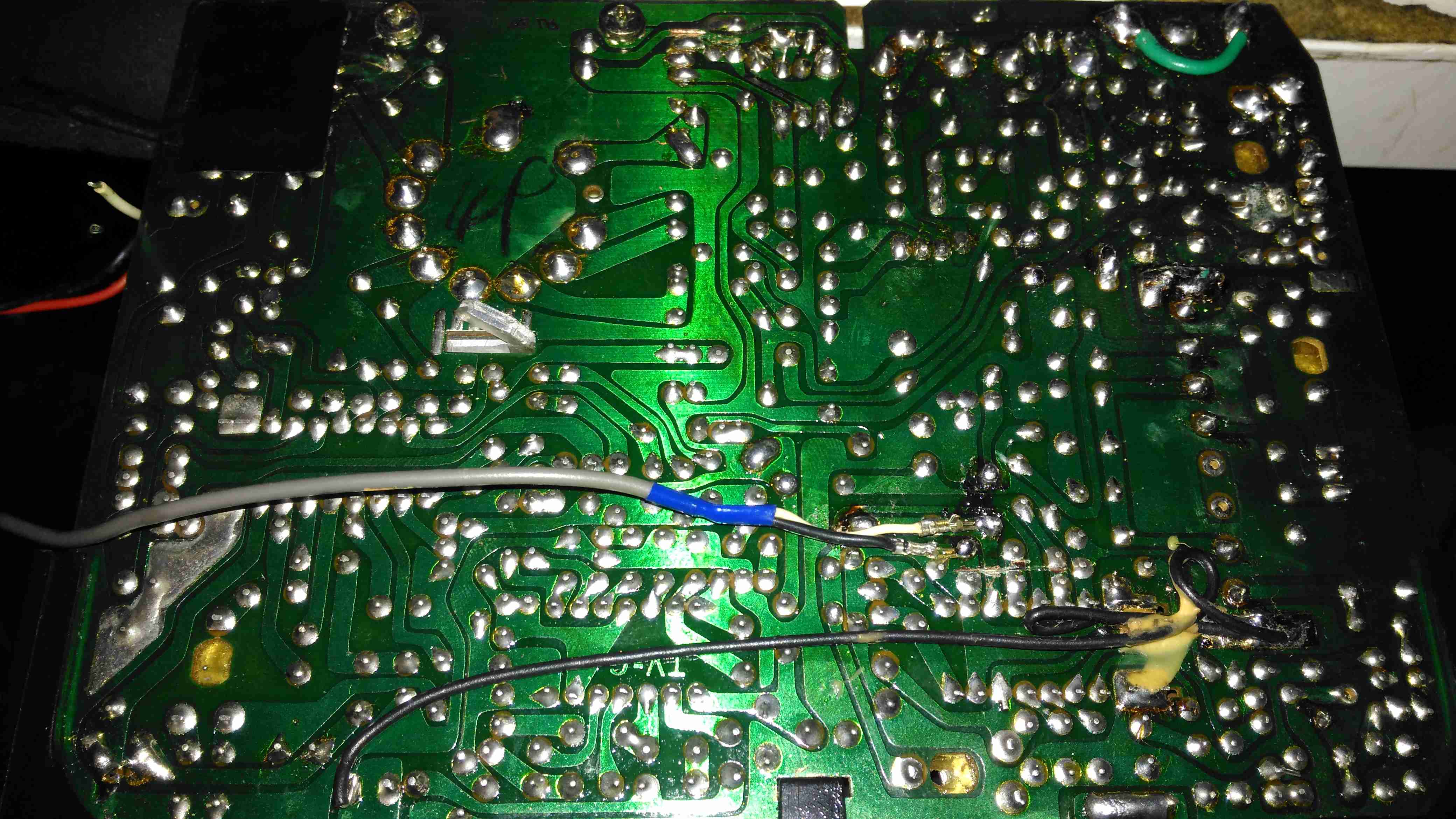
PCB Bottom
The PCB bottom shows the curved track layout typical of a hand taped out board. The soldermask is starting to flake off in places due to age, and there a couple of bodge wires completing a few ground traces. Respinning a board in those days was an expensive deal! Surprisingly, after all this time I’ve found no significant drift in the fixed resistors, but the carbon track potentiometers are drifiting significantly – 10KΩ pots are measuring as low as 8KΩ out of circuit. These will have to be replaced with modern versions, since there are a couple in timing-sensitive places, like the vertical & horizontal oscillator circuits.
Anode Cap Replaced
Here the anode cap has been replaced with a better silicone one from another TV. This should help keep the 6kV on the CRT from making an escape. This was an easy fix – pulling the contact fork out of the cap with it’s HT lead, desoldering the fork & refitting with the new cap in place.
Here I’ve replaced the important trimmers with new ones. Should help stabilize things a little.
Composite Injection Mod
Injecting a video signal is as easy as the other units. Pin 3 of the µPC1366C Video IF Processor is it’s output, so the track to Pin 3 is cut and a coax is soldered into place to feed in an external signal.
CRT In Operation
After hooking up a Raspberry Pi, we have display! Not bad after having stood idle for 30+ years.
Datasheets for the important ICs are available below:
[download id=”5690″]
[download id=”5693″]
[download id=”5696″]
Now the trolley is pretty much built, some burn-in testing is currently underway before it’s first trial-by-fire at Download Festival. There are a couple of minor issues that have needed fixing, since everything is enclosed in a pretty tight box.
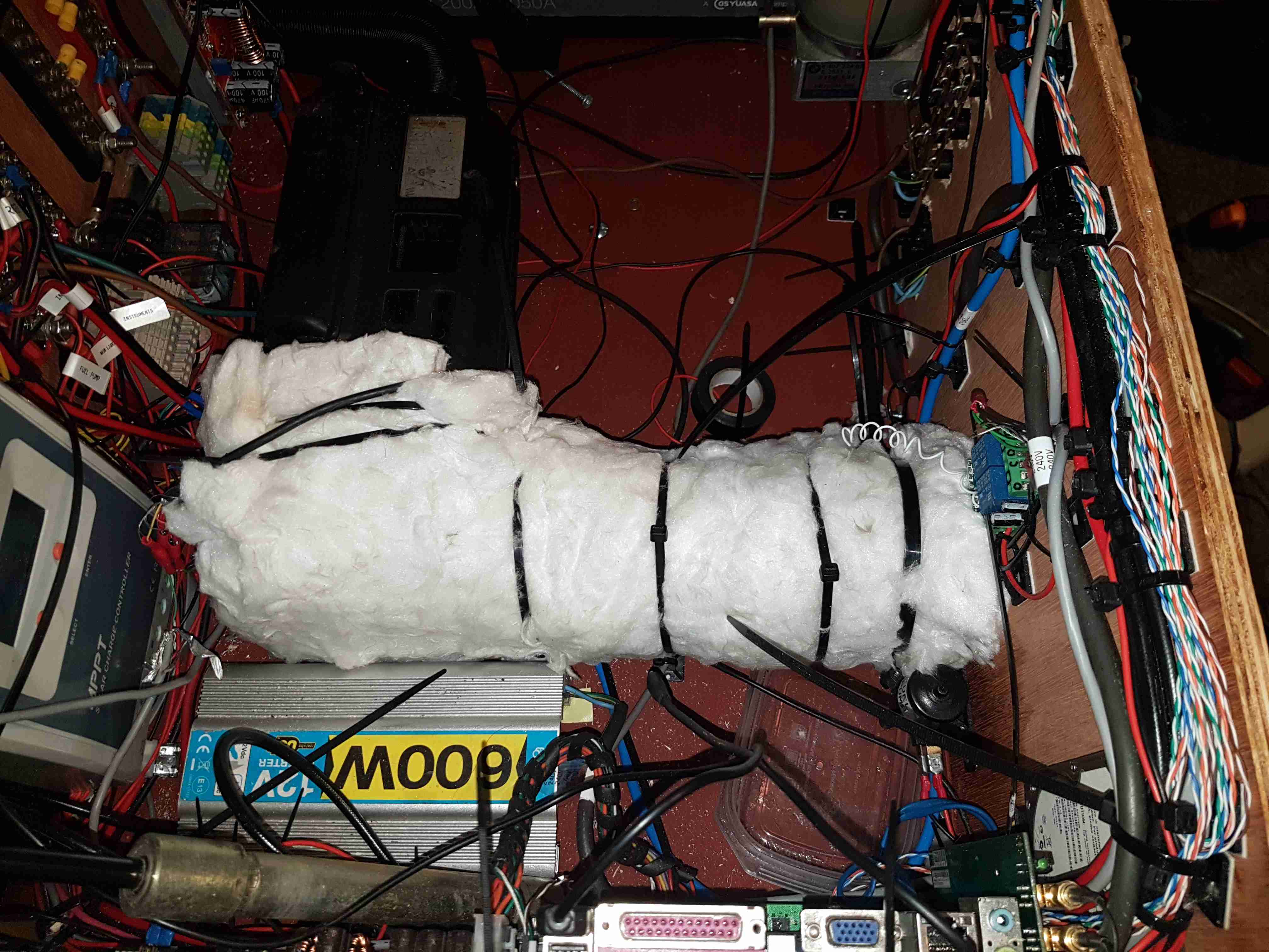
Lagging
The Eberspacher was the first point that needed sorting – the radiant heat from the hot air ducting was pretty much cooking everything around it – the inverter’s heatsink got to temperatures in the 50°C range. I pullsed some ceramic fibre lagging from a decomissioned domestic oven, and entirely lagged the hot end of the heater, securing everything with cable ties. Good stuff this, the inside of the box now hardly even warms up, nearly all of the heat going out through the vent where it’s needed.
The intake was also an issue, since these heaters adjust their power levels based on inlet air temperature, pulling the air from inside the box was infeasible, since within a few minutes the heater thinks the ambient temperature has reached 30°C, resulting in a shutdown. Another vent has been fitted in the back panel, drawing cool air into the heater’s fan.
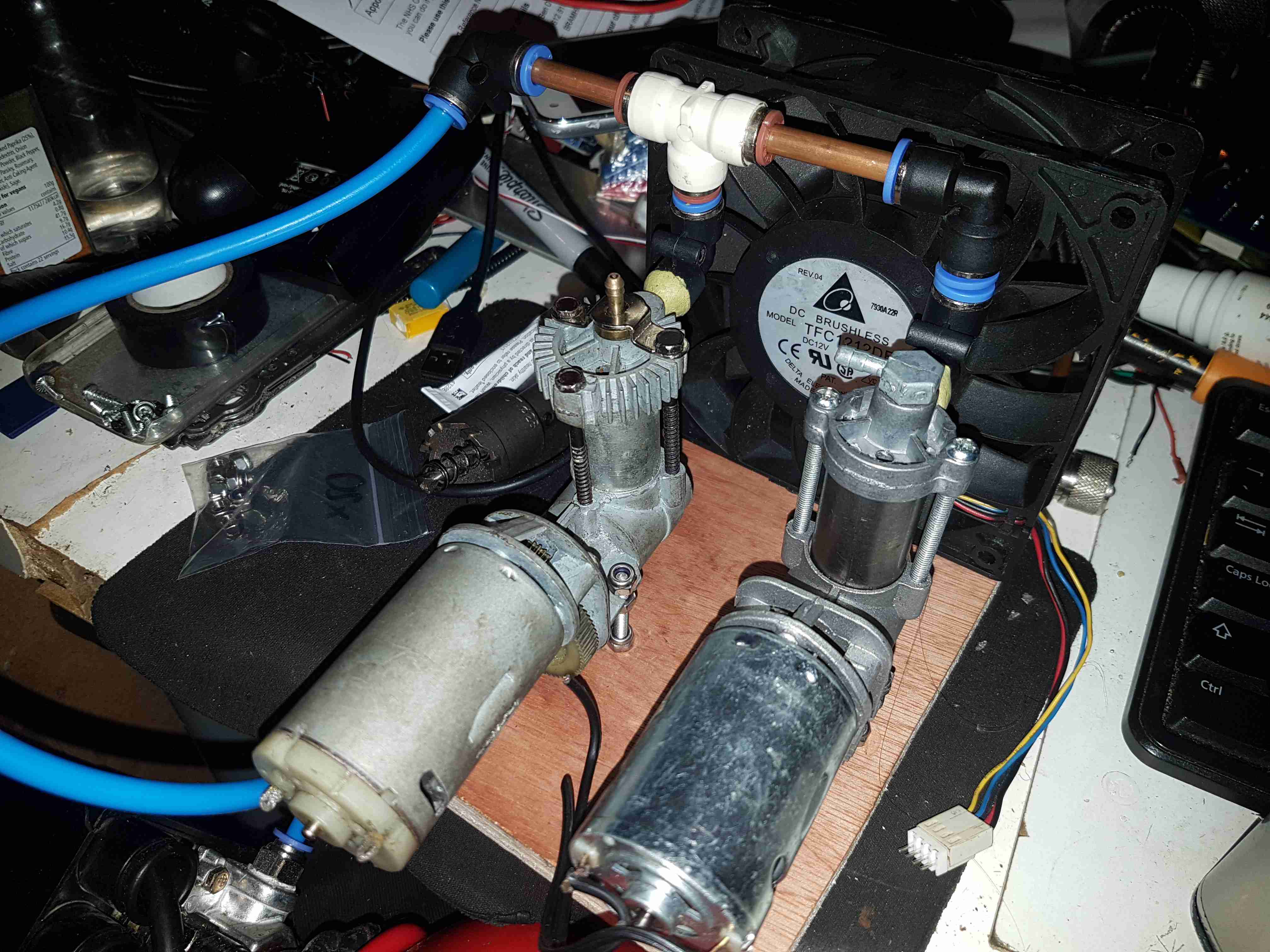
Finally, meet FrankenCompressor:
FrankenCompressor
I didn’t have the time to order a proper 12v compressor in time for this year, so after some rummaging around in the parts bin & came up with a couple of 12v car tyre inflator type compressor units. These are pretty crap for proper air compressor use, but they should survive just long enough to get me through this year. They’re mounted to a wooden board, with a large 120mm high-speed server fan mounted on the end, blowing a huge amount of air over the cylinders to help cool them down. Output is channelled through a couple of modified 6mm push-fit pneumatic fittings epoxied onto the factory hose barbs. Copper tubing helps cool the compressed air before the transition to poly tube.
Since I do festivals every year, along with a couple of other camping trips if the weather is good enough, I’ve been taking equipment with me for years in flight cases to make things more comfortable. Things like a large battery to power lights & device charging, an old Eberspacher diesel heater for the times when the weather isn’t great, and an inverter to run the pumps built into airbeds.
Red Diesel / Heating Oil is my fuel of choice for camping purposes, as it’s about the safest fuel around, unlike Butane/LPG it is not explosive, will not burn very readily unless it’s atomized properly & it’s very cheap. Paraffin is an alternative fuel, but it’s expensive in the UK, at about £12 per 5L.
The Hexamine-based tablet fuels the UK festivals promote is nasty stuff, and the resulting combustion products are nastier still. (Things like Hydrogen Cyanide, Formaldehyde, Ammonia, NOX). They also leave a sticky black grok on every cooking pot that’s damn near impossible to remove. Meths / Trangia stoves are perfectly usable, but the flame is totally invisible, and the flammability of alcohol has always made me nervous when you’ve got a small pot of the stuff boiling while it’s in operation in the middle of a campsite filled with sloshed festival goers. A single well-placed kick could start a massive fire.
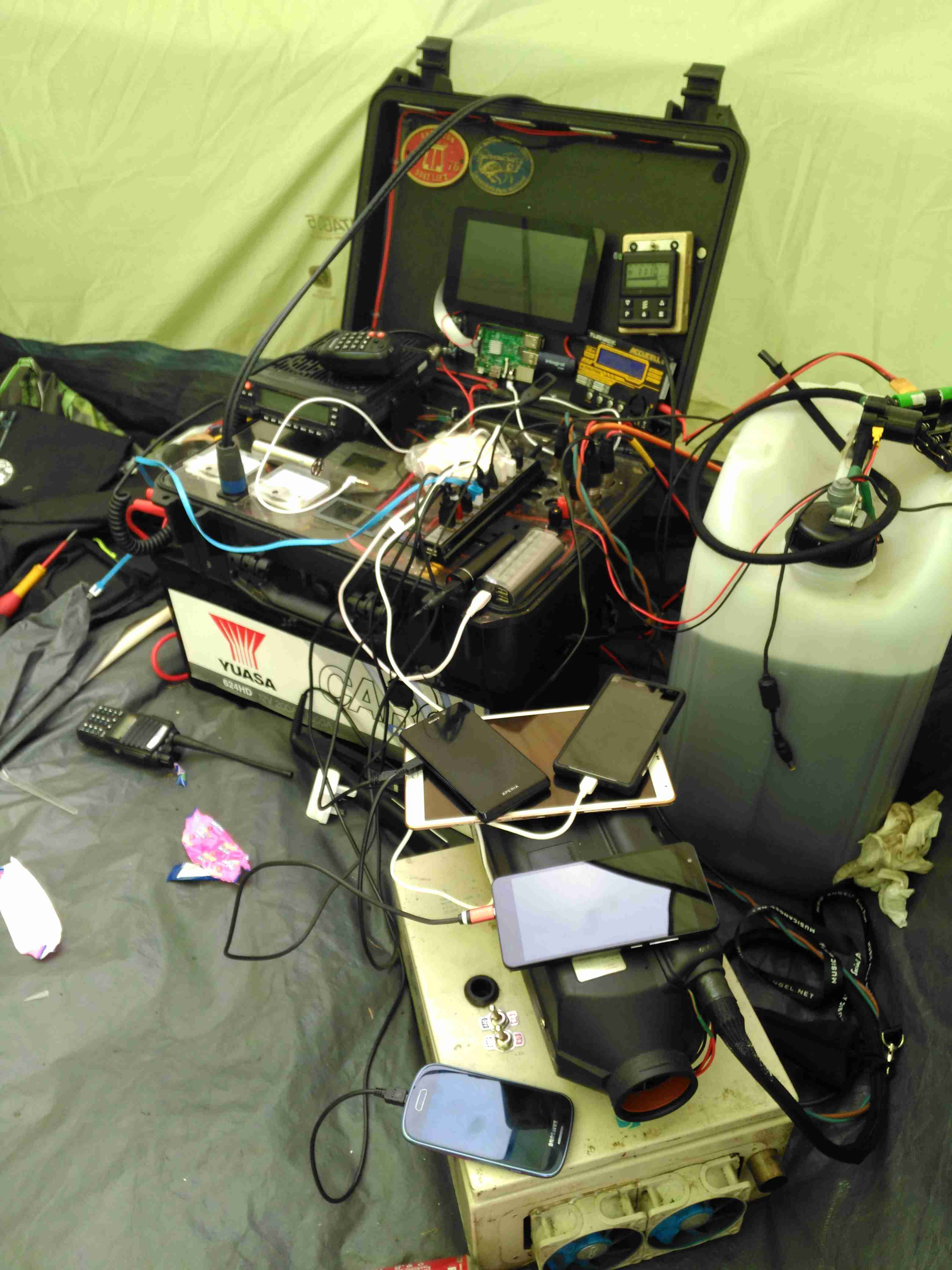
Previous System
Over the years the gear has evolved and grown in size, so I decided building everything into one unit on wheels would be the best way forward. I’ve been working on this for some time, so it’s time to get some of the details on the blog! Above you can see the system used for last year’s camping, the heater is separate, with a 25L drum of heating oil, the battery is underneath the flight case containing all the power components, and it’s currently charging All The Things.
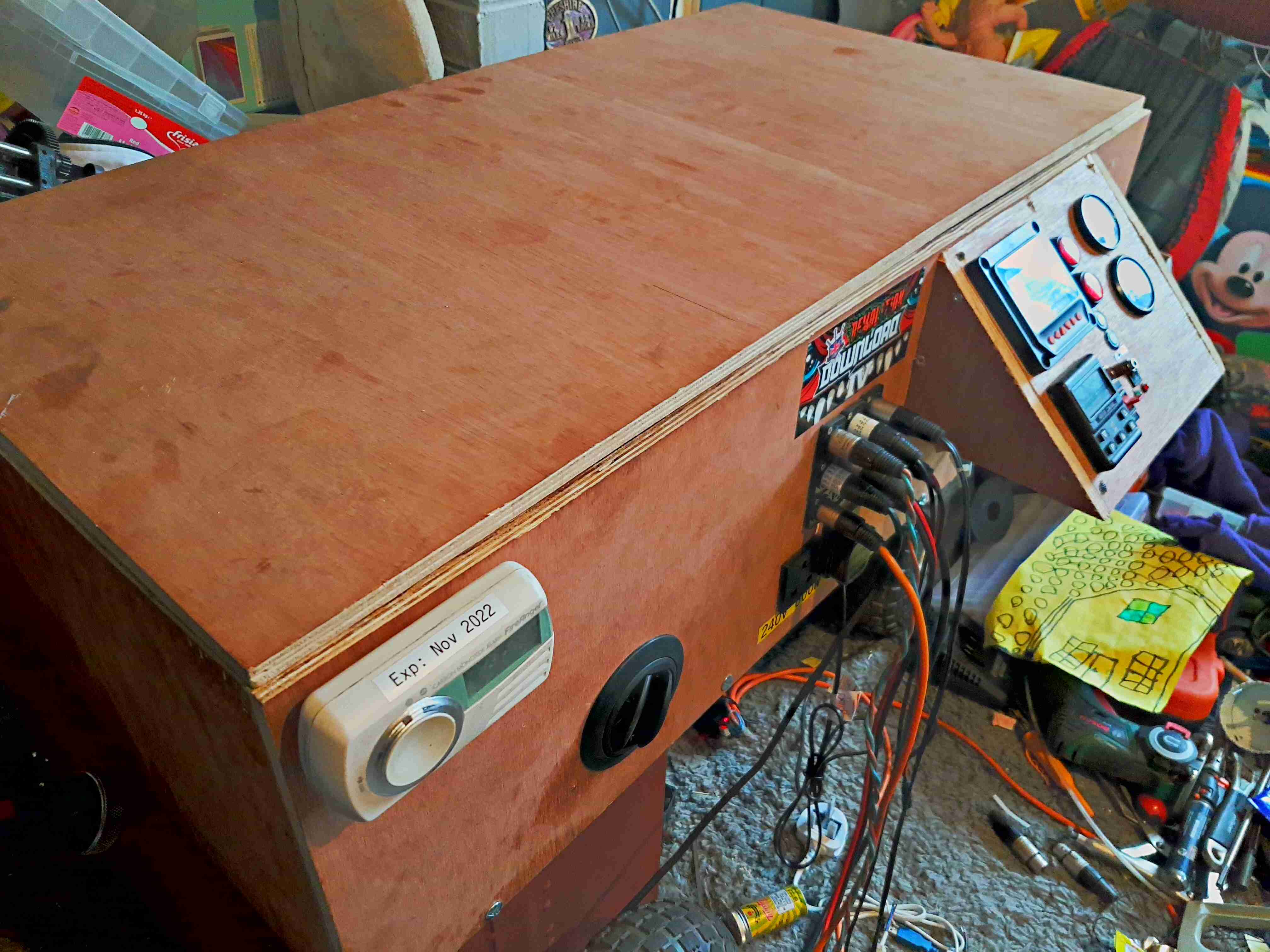
Overview
Above is the new unit almost finished, the bottom frame is a standard eBay-grade 4-wheel trolley with a few modifications of my own, with a new top box built from 12mm hardwood marine plywood. This top is secured in place with coach bolts through the 25mm angle iron of the trolley base. The essential carbon monoxide detector is fitted at the corner.
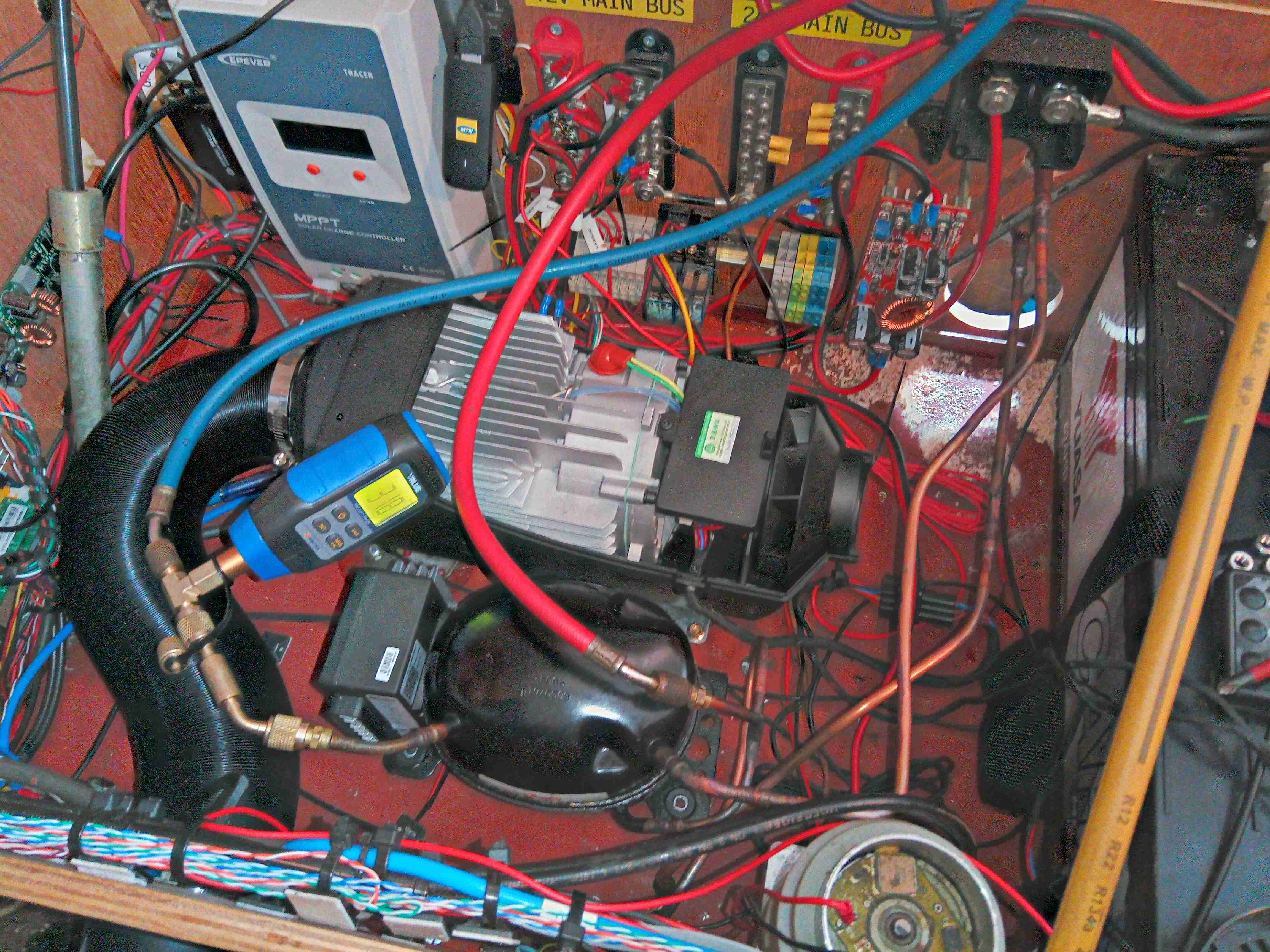
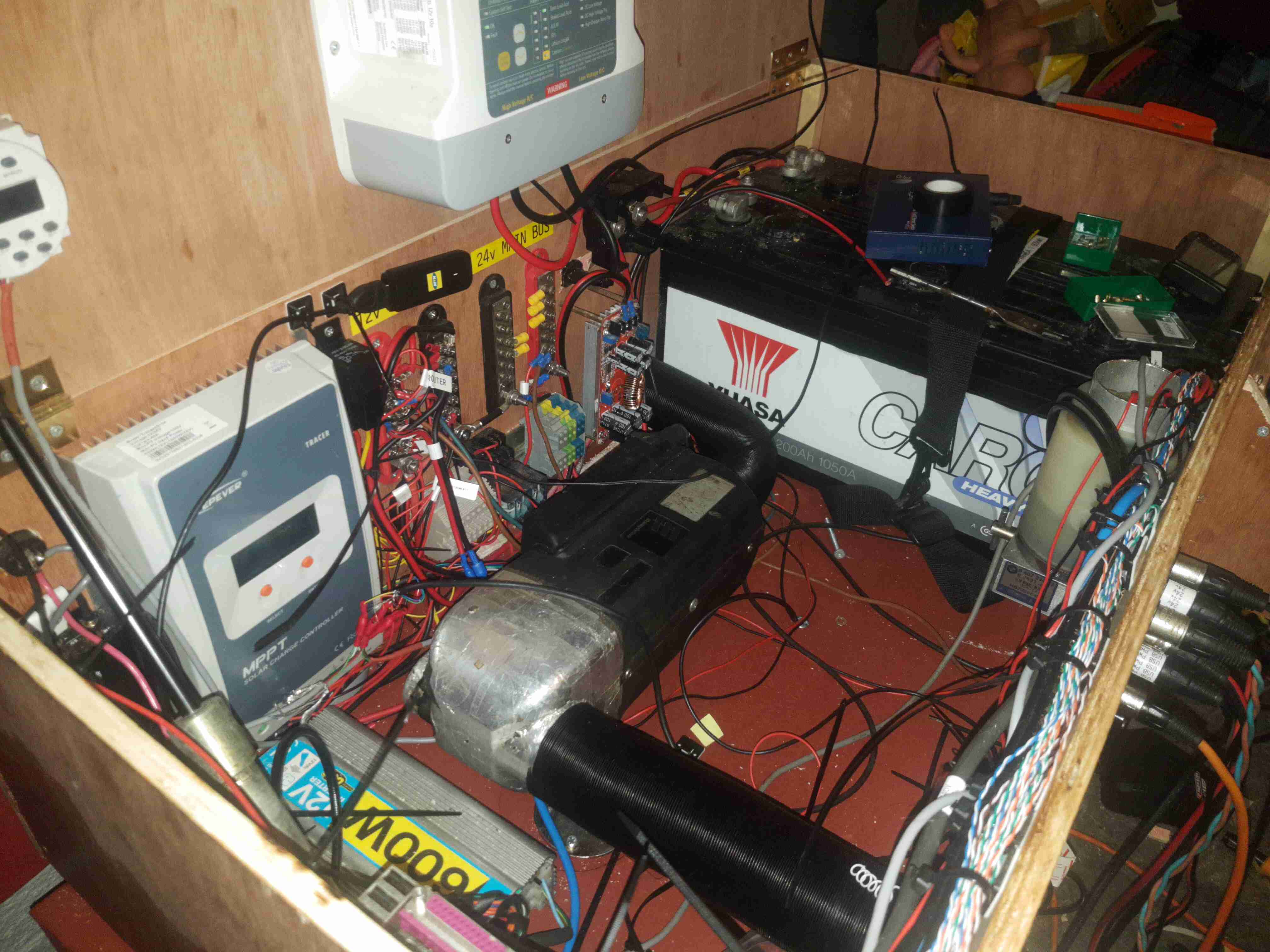
Internal View
The inside gets a bit busy with everything crammed in. The large Yuasa 200Ah lead-acid battery is at the far end, with it’s isolation switch. Right in the middle is the Eberspacher heater with it’s hot air ducting. I’ve fitted my usual 12/24v dual voltage system here, with the 24v rail generated from a large 1200W DC-DC converter.
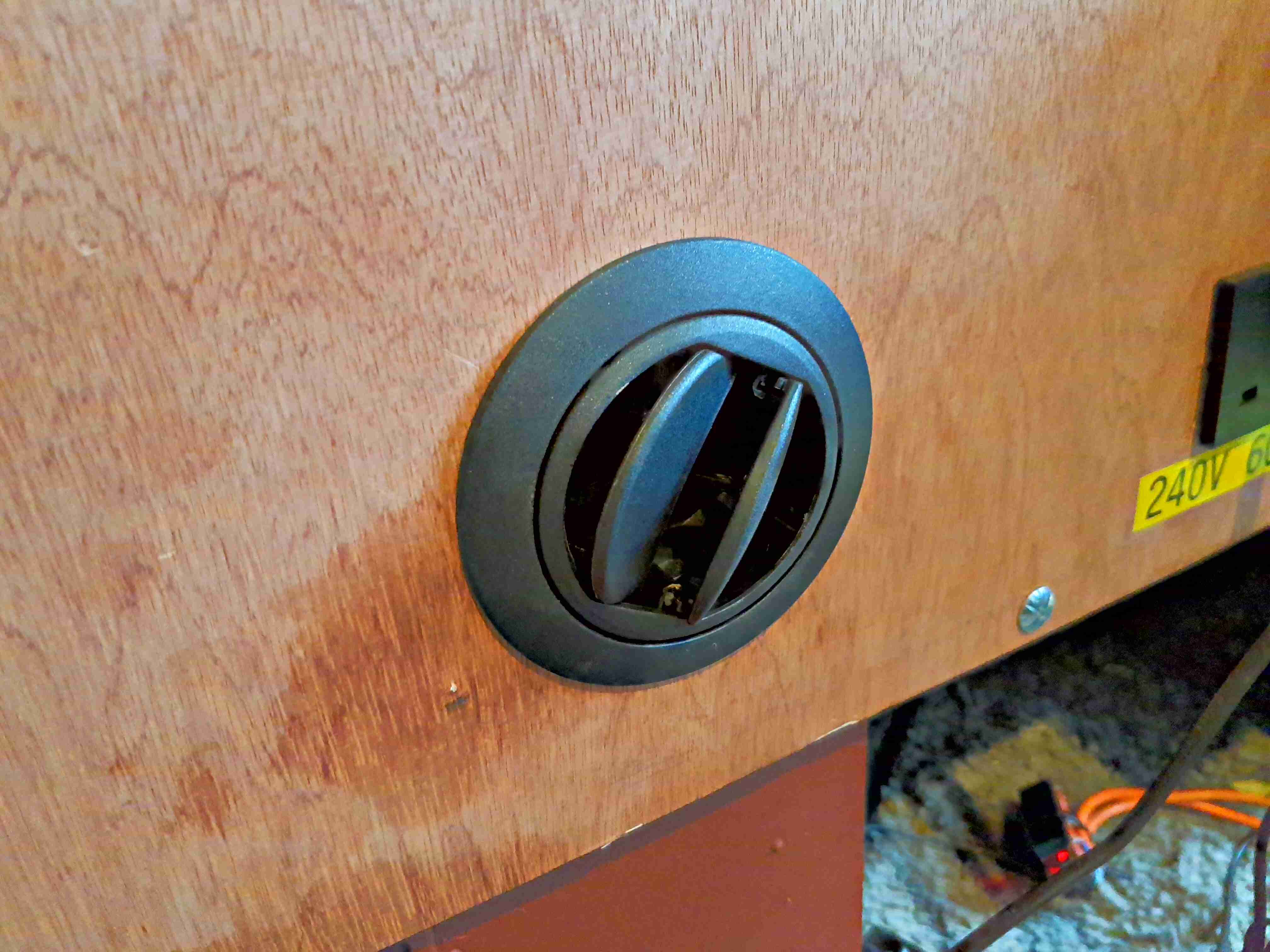
Heater Vent
The hot air duct for the heater is fed out through a standard vent in the front. Very handy for drying out after a wet day.
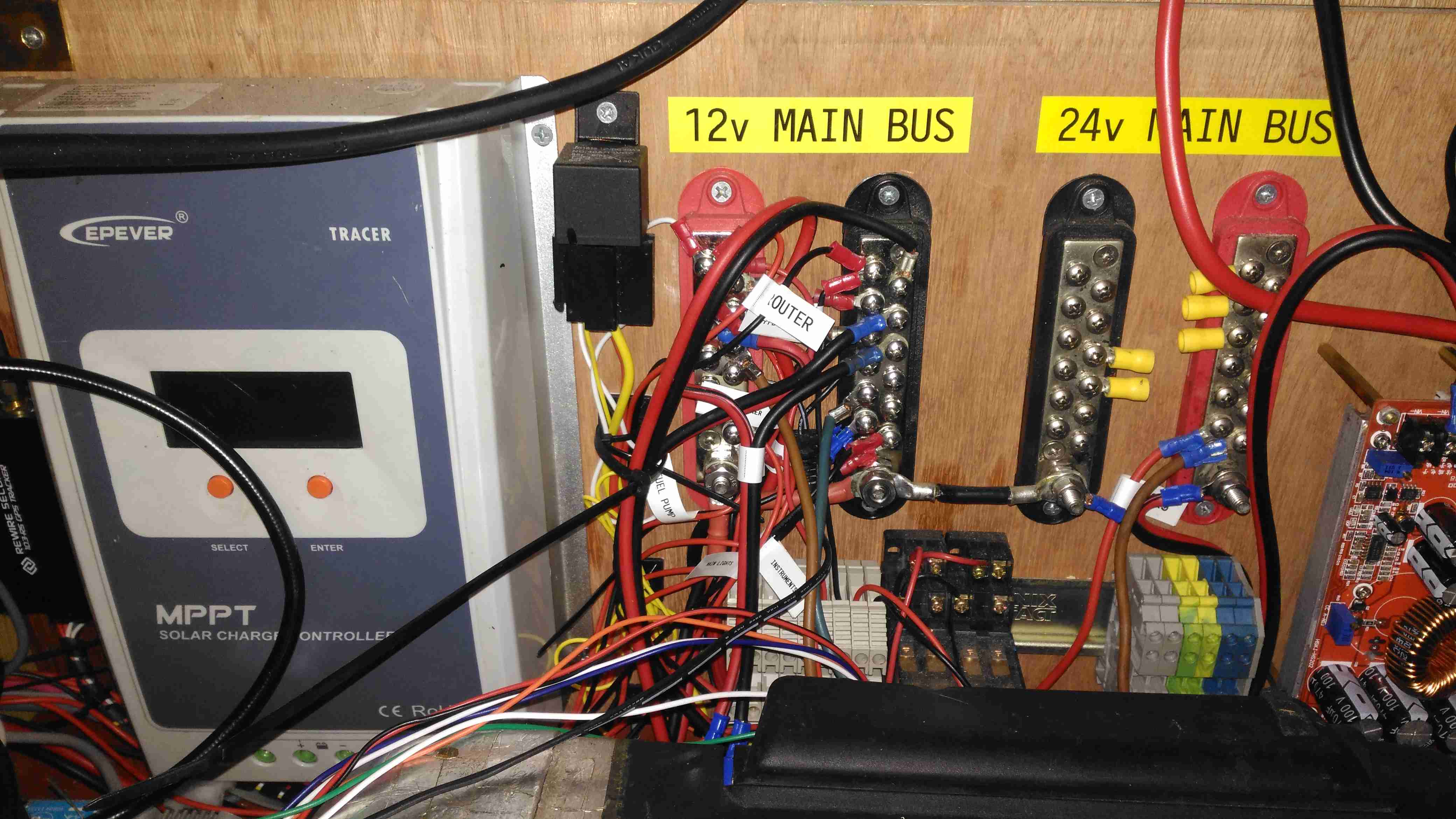
Main Bus Bars & Solar Controller
Here’s a closeup of the distribution bus bars, with both negative rails tied together in the centre to keep the positives as far away from each other as possible, to reduce the possibility of a short circuit between the two when working on the wiring. The EpEver Tracer 4210A MPPT Solar Charge Controller is on the left, tucked into the corner. This controller implements the main circuit protection for the battery, having a 40A limit. Individual circuits are separately fused where required. Solar input on this unit is going to be initially provided by a pair of 100W flexible panels in series for a 48v solar bus, the flexible panels are essential here as most of the festivals I attend do not allow glass of any kind onsite, not to mention the weight of rigid panels is a pain.
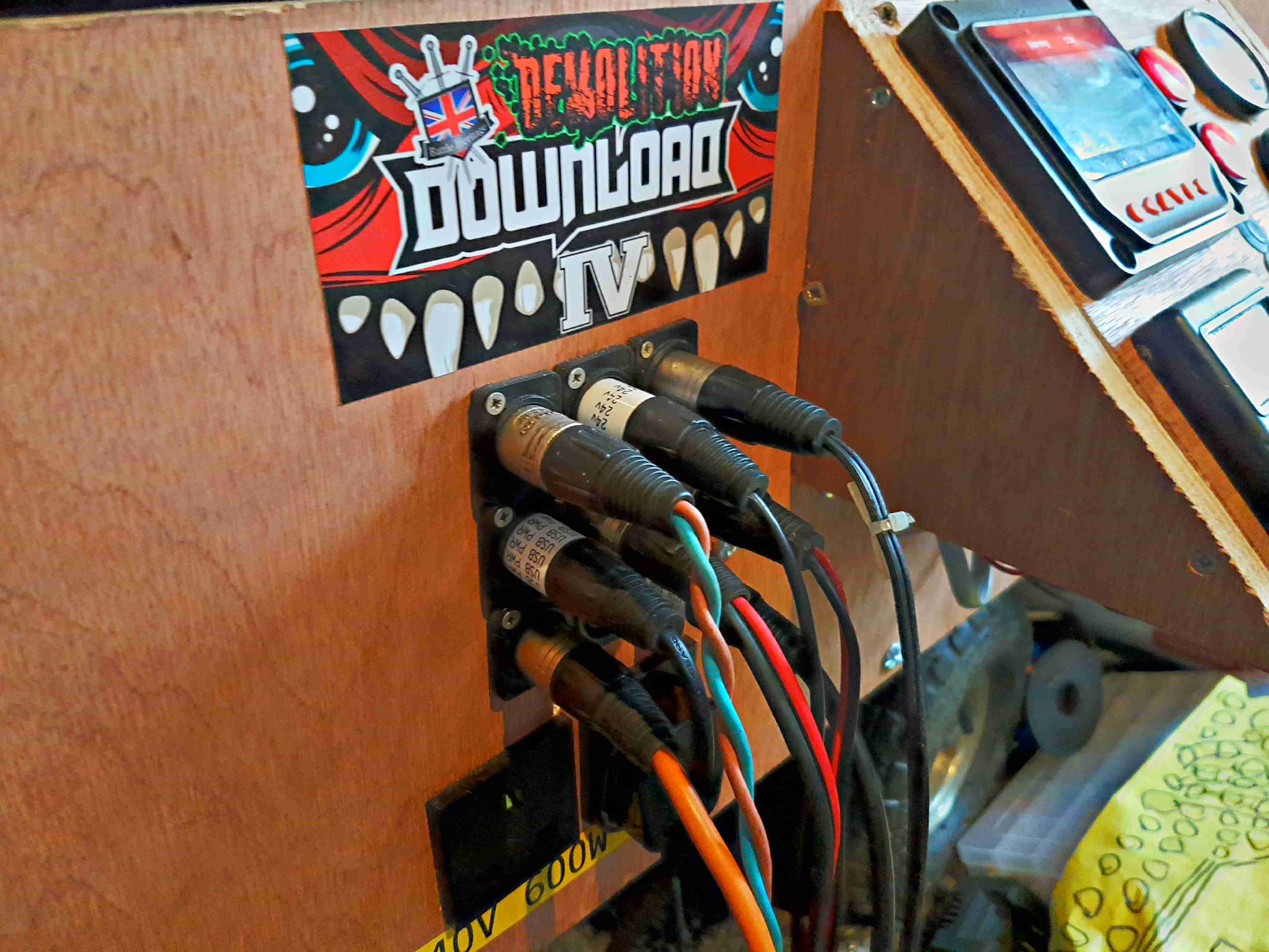
DC Output Sockets
I’ve stuck with the 3-pin XLR plugs for power in this design, giving both the 12v rail, 24v rail & ground.
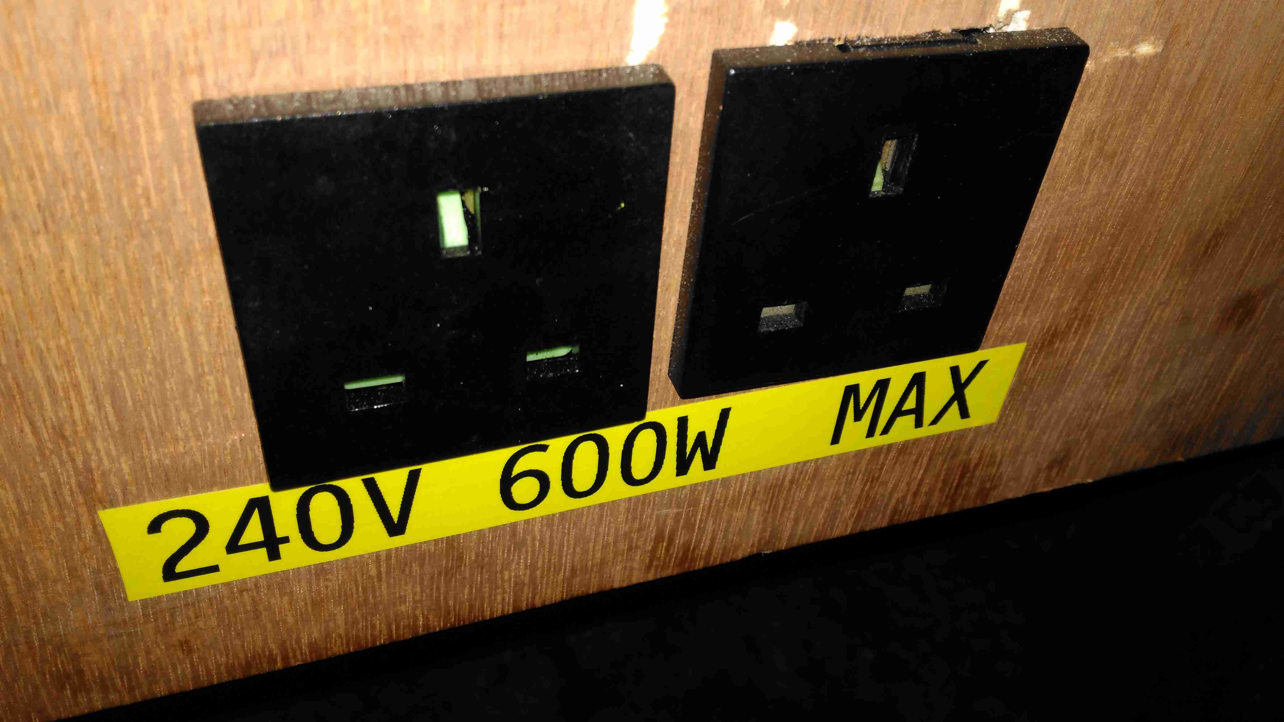
Inverter Outputs
Tucked under the DC outputs are a pair of panel sockets for the 600W inverter. This cheapo Maplin unit is only usually used to pump up air beds, so I’m not expecting anyone to pull anything near max output, but a warning label always helps.
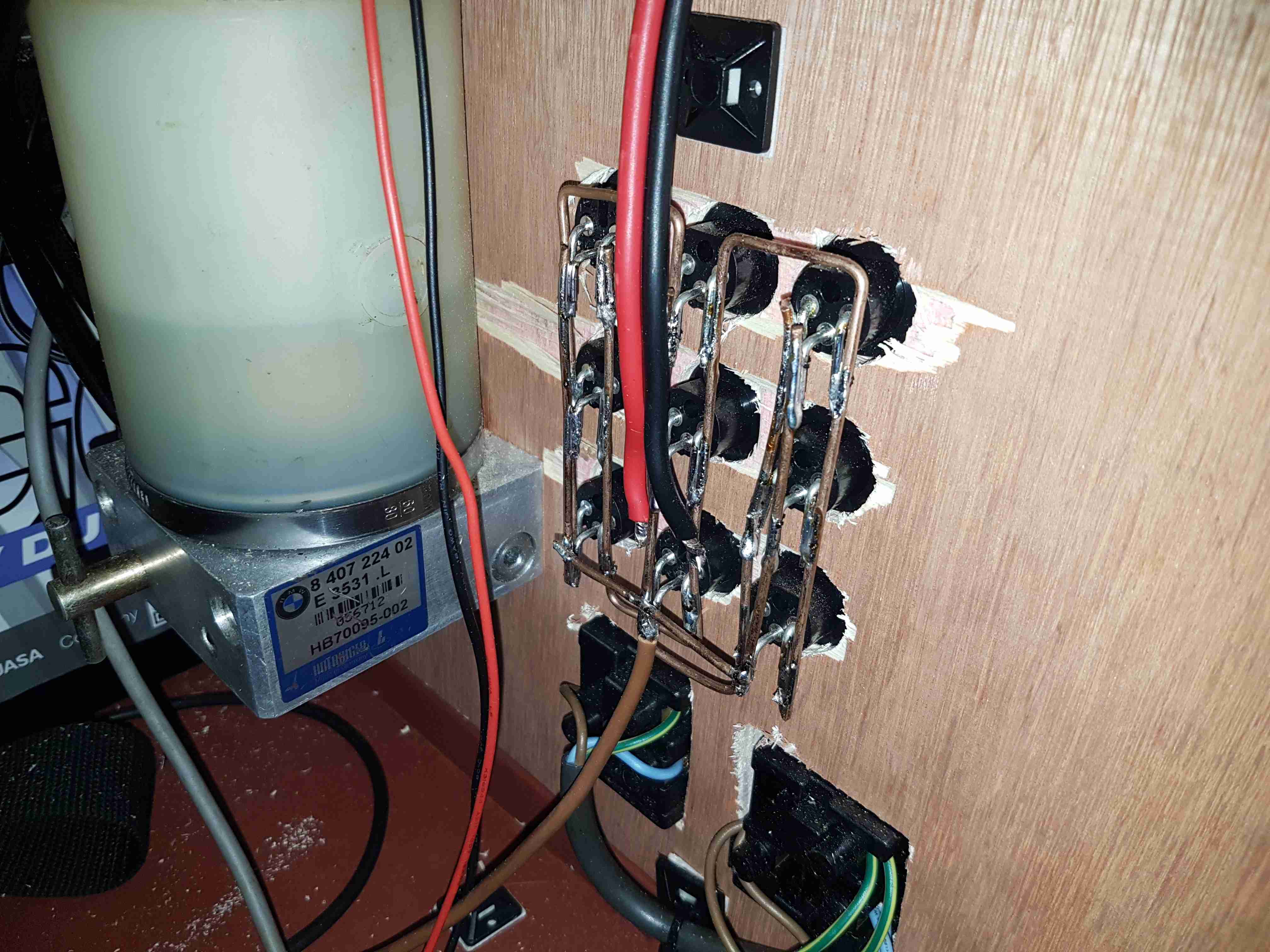
Power Socket Wiring
Behind the front panel is the hardwiring for the power sockets. The DC jacks are connected together using 2mm solid copper wire, bent into bus bars.The mains wiring underneath is a simple radial circuit straight from the inverter. The large cylinder on the left is a hydraulic pump from a BMW Z3, which runs a hydraulic cylinder for lifting the lid of the top box, used simply because I had one in the box of junk.
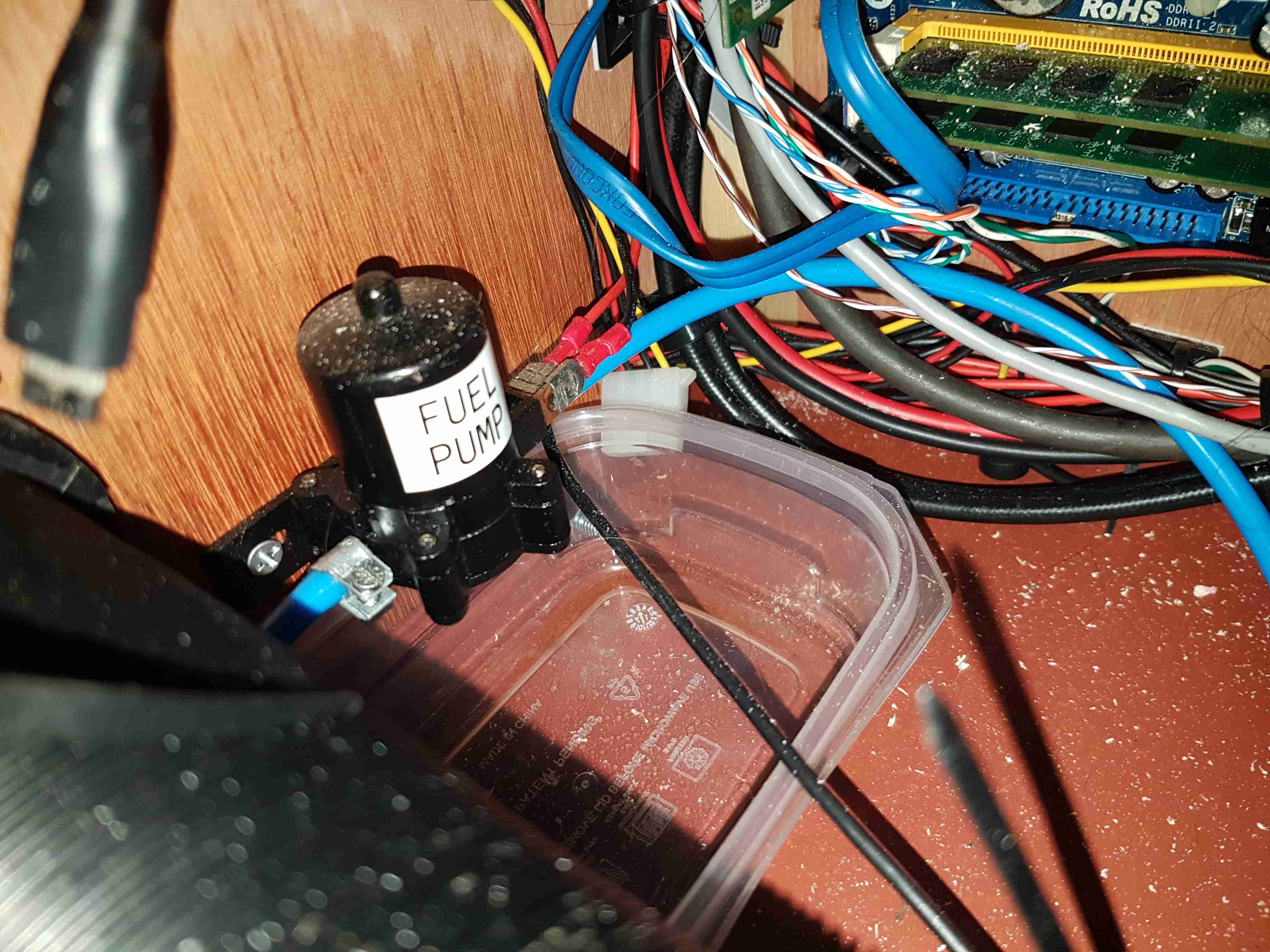
Fuel Pump
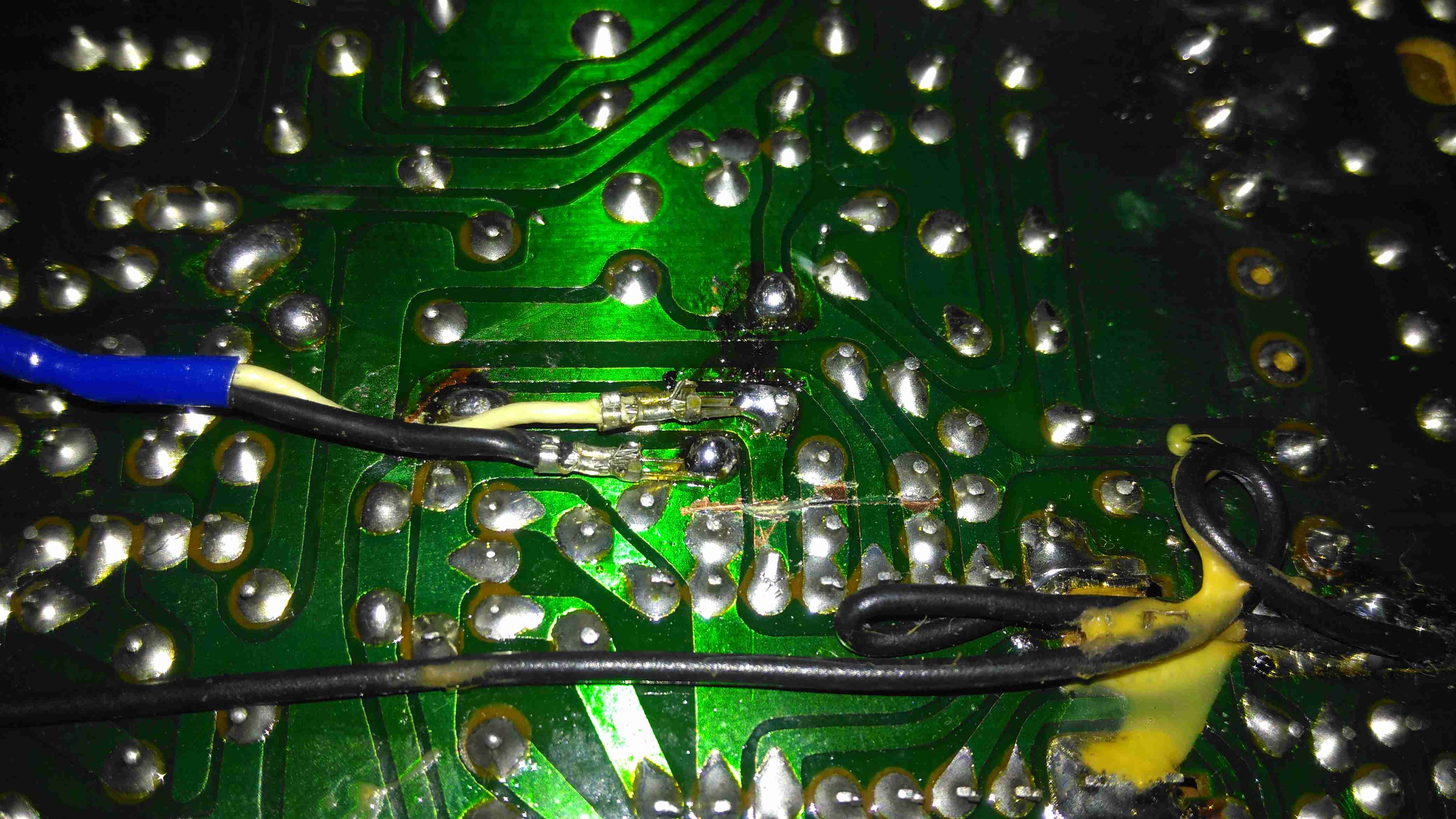
External fuelling is dealt with by a small gear pump, this is used to fuel up the Optimus Stove & Petromax Lantern. This is in fact a car windscreen wash pump, but it has coped well with pumping hydrocarbons, it currently has a small leak on the hose connections, but the seals are still entirely intact.
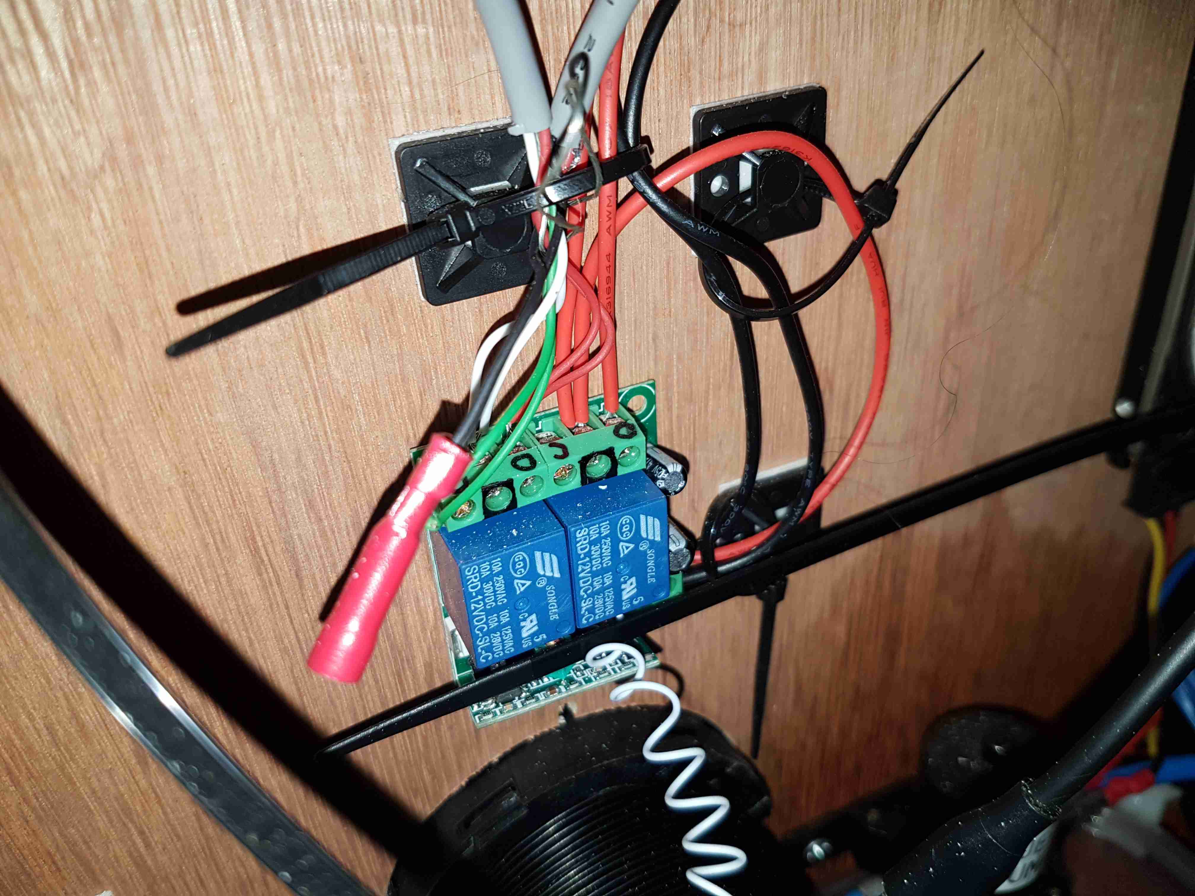
Remote Relays
There’s a small remote relay module here, for switching the DC output for lighting & the heater from afar. Very useful when it’s dark, since there’s no need to fumble around looking for a light switch. A car-style fob on my keyring instead.
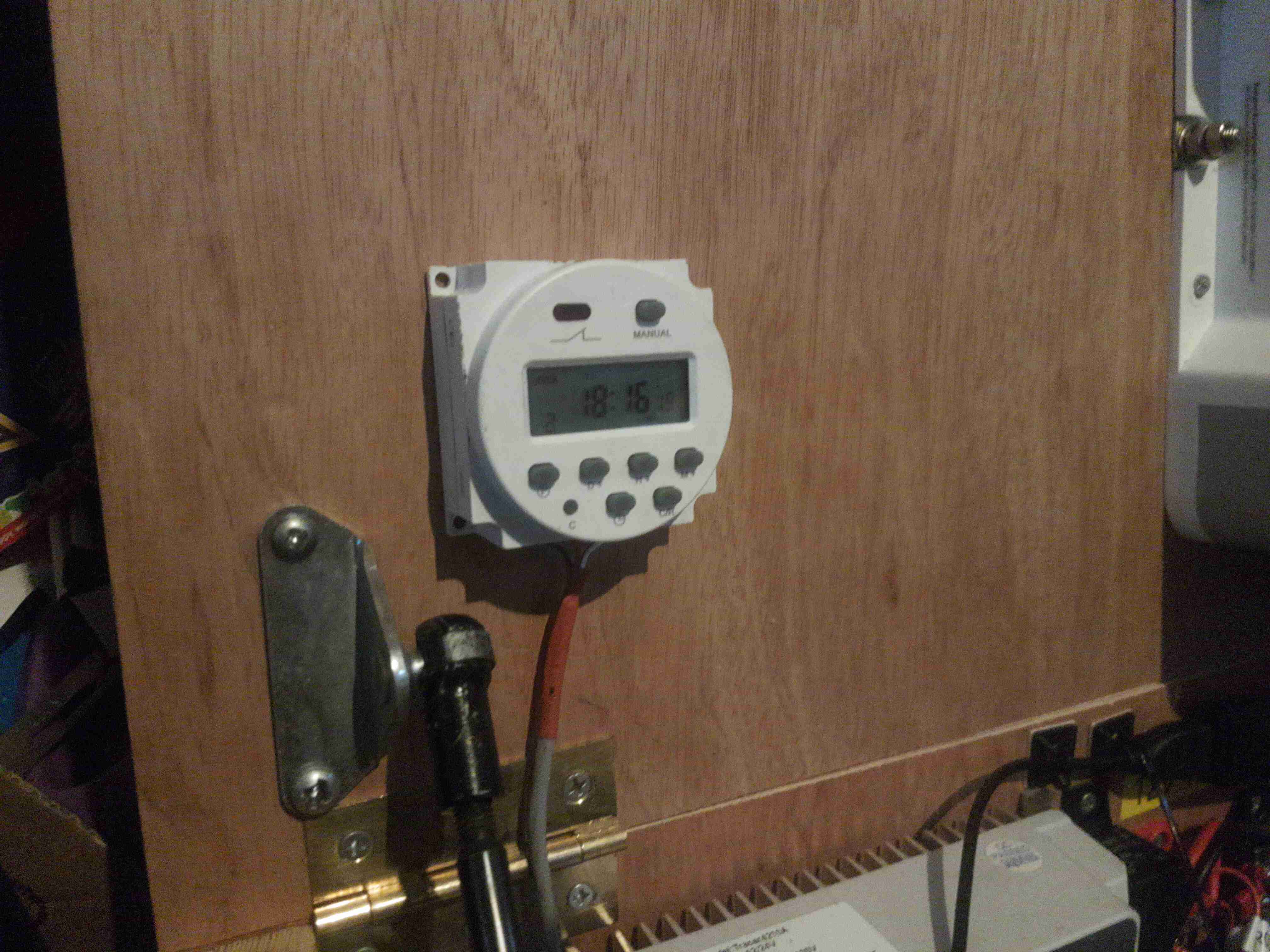
Heater Timer
Since the Eberspacher 701 controller I have is an ex-BT version, it’s very limited in it’s on time, a separate timeswitch is fitted to control the heater automatically. Being able to return to a nice warm tent is always a bonus.
Just to the left can be seen the top ball joint for the hydraulic cylinder that lifts the top of the box.
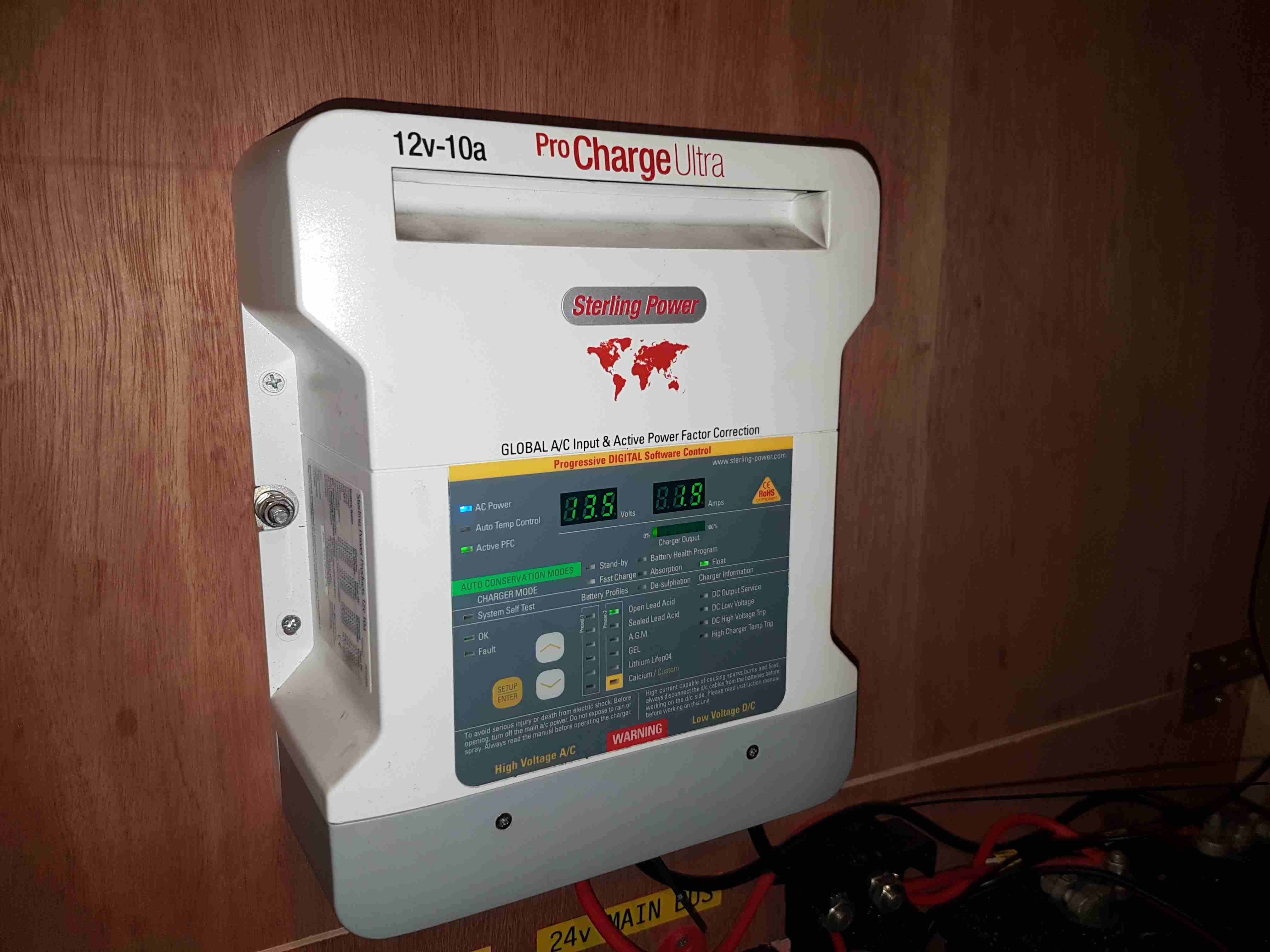
Battery Charger
The final large component is the battery charger. This unit will maintain the battery when the trolley isn’t being used.
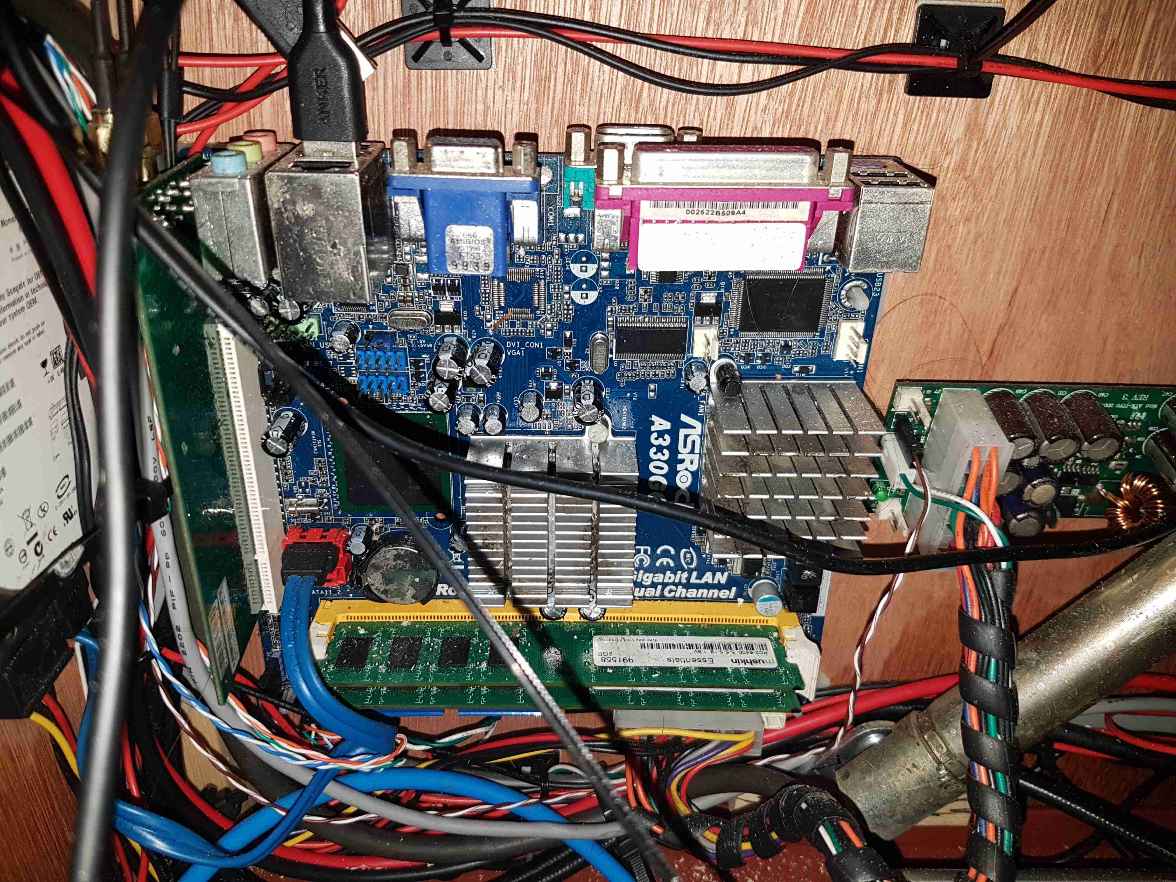
Router Motherboard
On the left side is the old Atom motherbaord used to provide a 4G router system. This unit gets it’s internet feed from a UMTS dongle & provides a local WiFi network for high speed connectivity. The bottom of the hydraulic cylinder is visible in the bottom right corner.
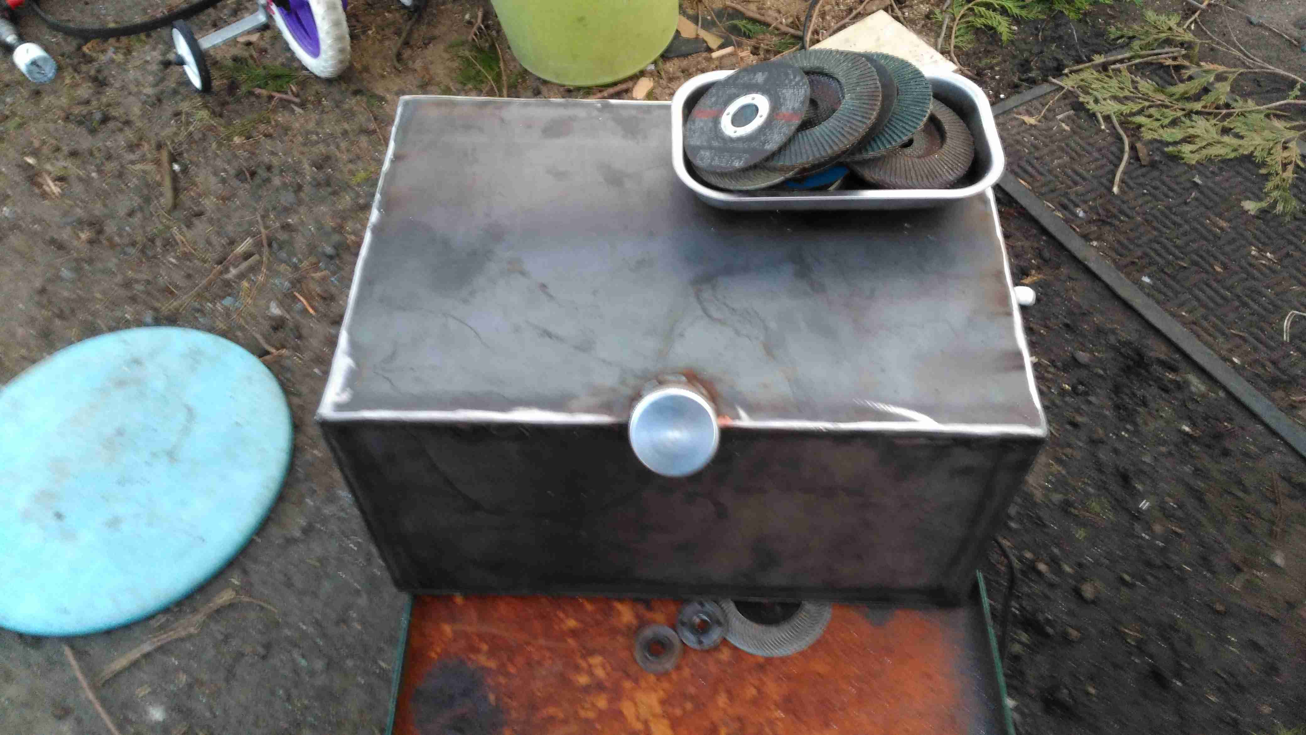
Fuel Tank Completed
Since the Eberspacher obviously needs fuel, a tank was required. In previous years I’ve used jerry cans for this purpose, but this trolley is supposed to have everything onboard, for less setup time. The tank is constructed from 3mm steel plate, MIG welded together at the seams to create a ~40L capacity. The filler neck is an eBay purchase in Stainless Steel. No photos of the tank being welded together, as I was aiming to beat sunset & it’s very difficult to operate a camera with welding gauntlets on 😉
The tank is the same width as the trolley frame, so some modification was required, having the wheels welded directly to the sides of the tank. This makes the track wider at the rear, increasing stability.
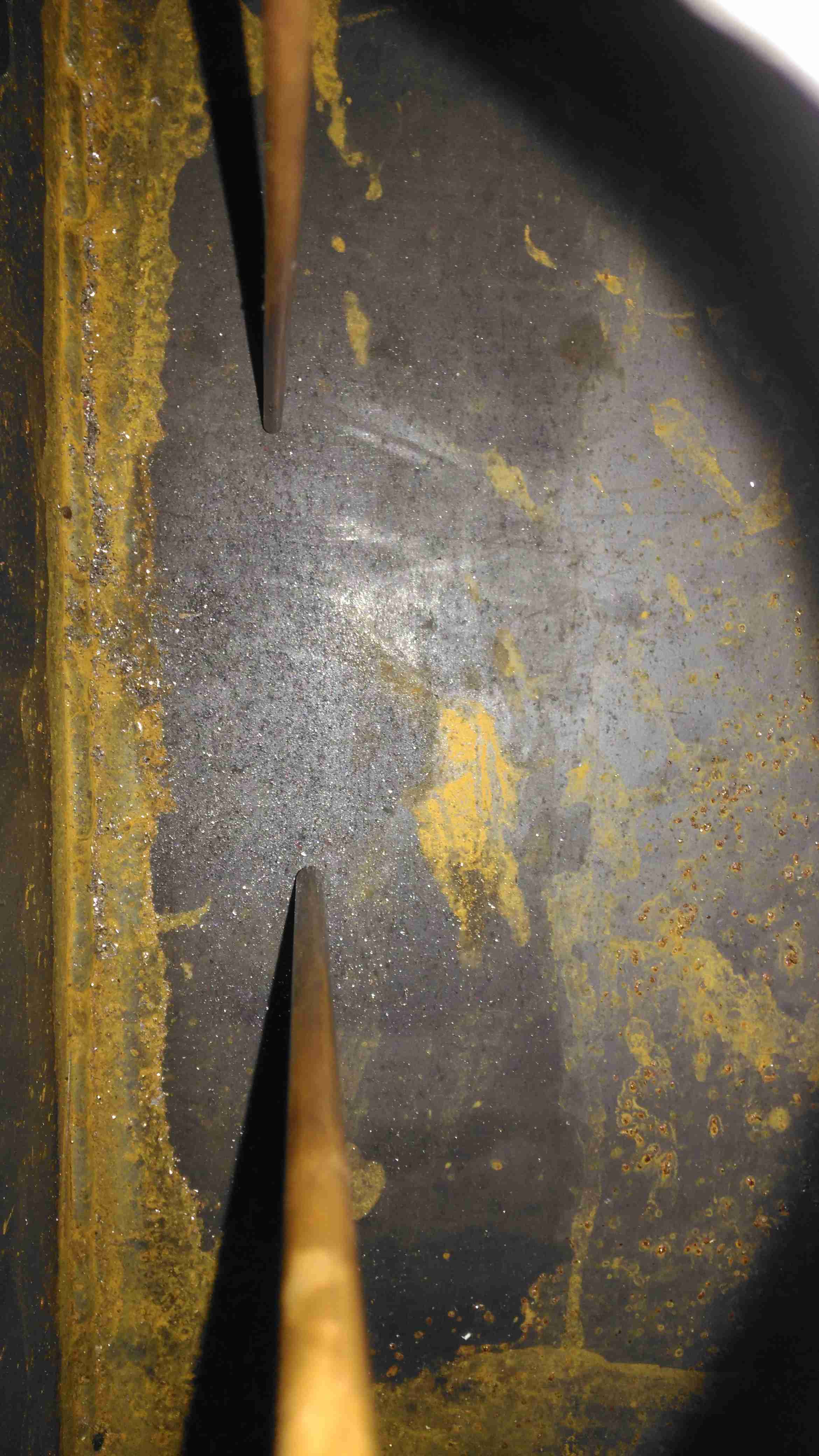
Fuel Dip Tubes
A quick view inside the tank through the level sender port shows the copper dip tubes for fuel supply to the heater, and an external fuel hose for my other fuel-powered camping gear. These tubes stop about 10mm from the bottom of the tank to stop any moisture or dirt from being drawn into the pumps.
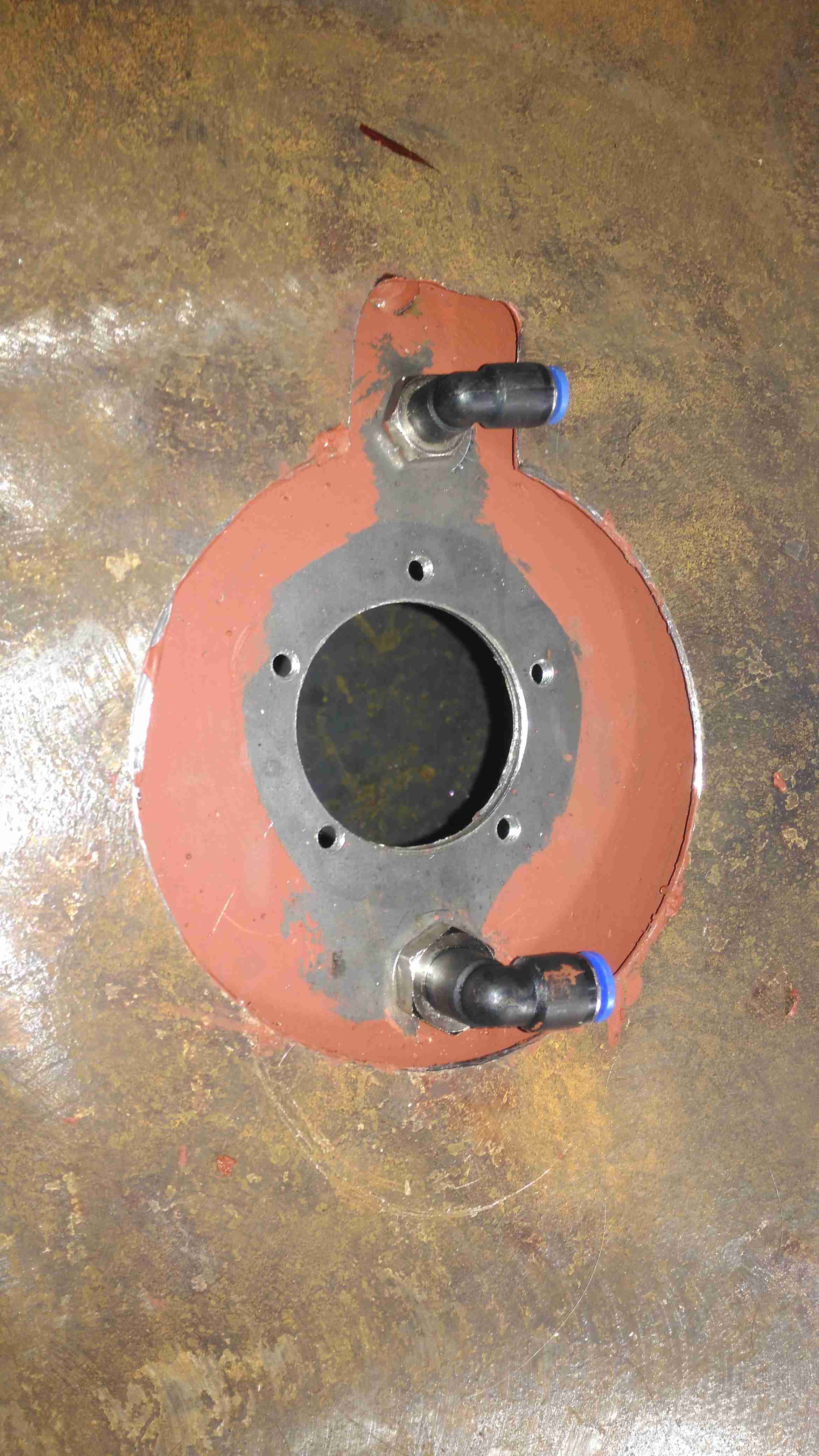
Fuel Feeds & Level Sender Port
The top of the tank is drilled for the fuel fittings & the level sender and has already been painted here. The 1mm base plate has yet to be painted.
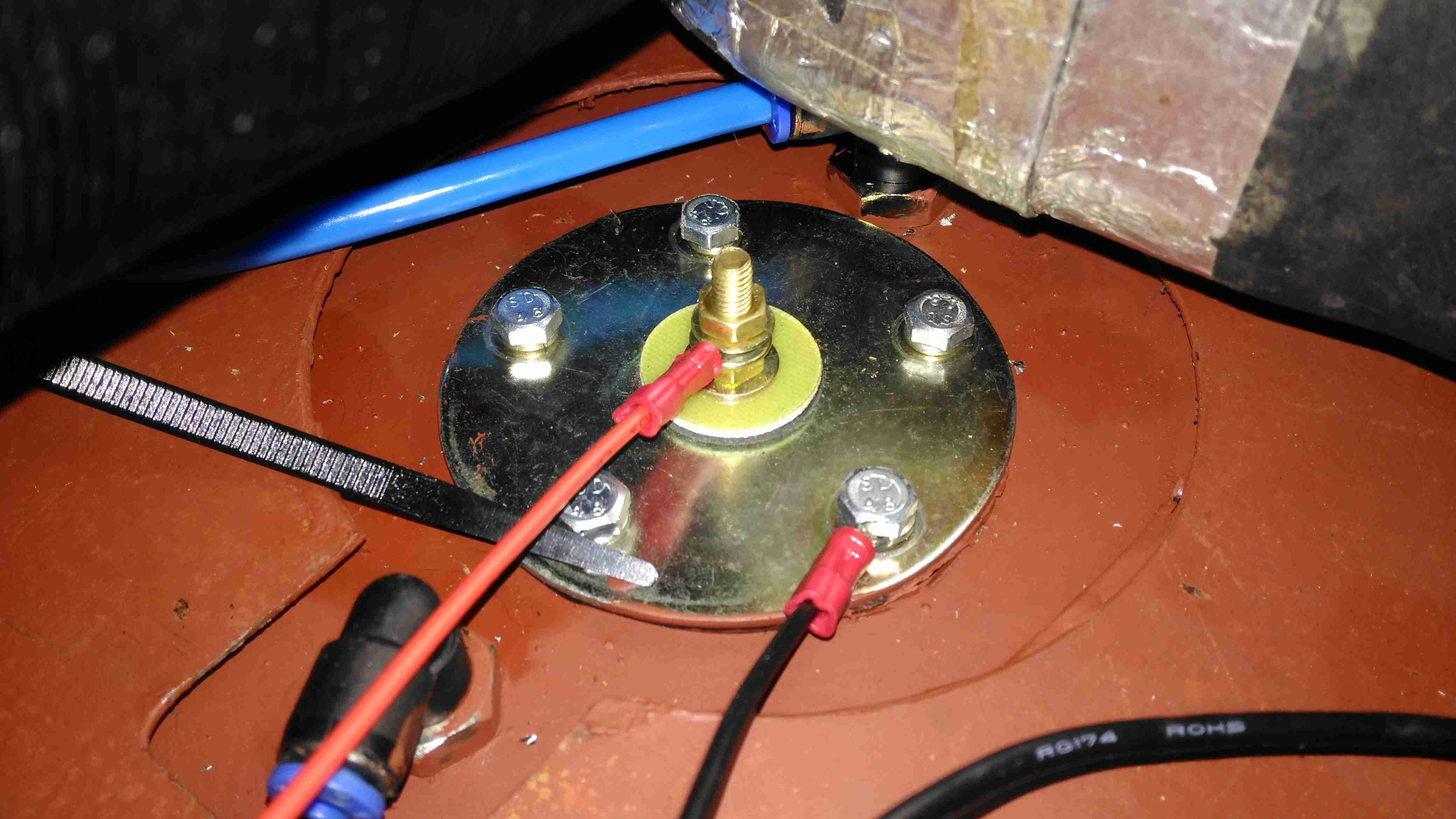
Level Sender Installed
Touching up the paint & fitting the sender is the last job for this part. The mesh bottom of the trolley has been replaced by a 1mm steel sheet to support the other parts, mainly the heater. Fuel lines are run in polyurethane tubing to the fuel pumps.
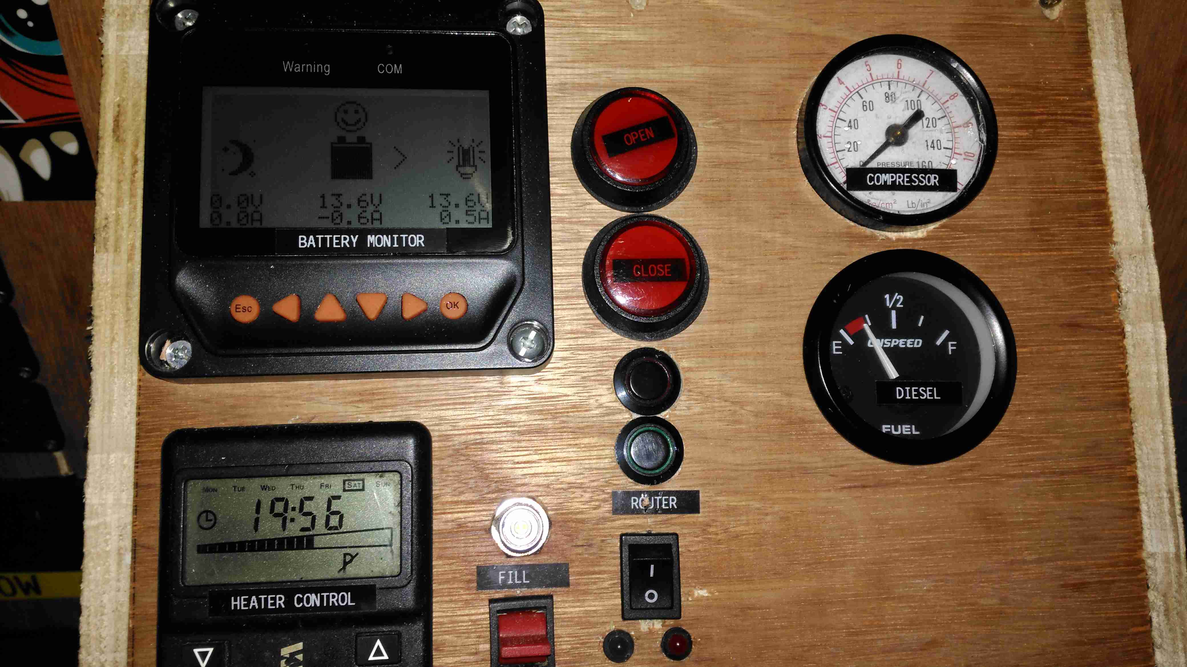
All the instruments & controls are on a single panel, with the Eberspacher thermostat, external fuelling port & pump switch, inverter control, the solar controller monitor panel, cover buttons, router controls, compressed air & fuel gauges.
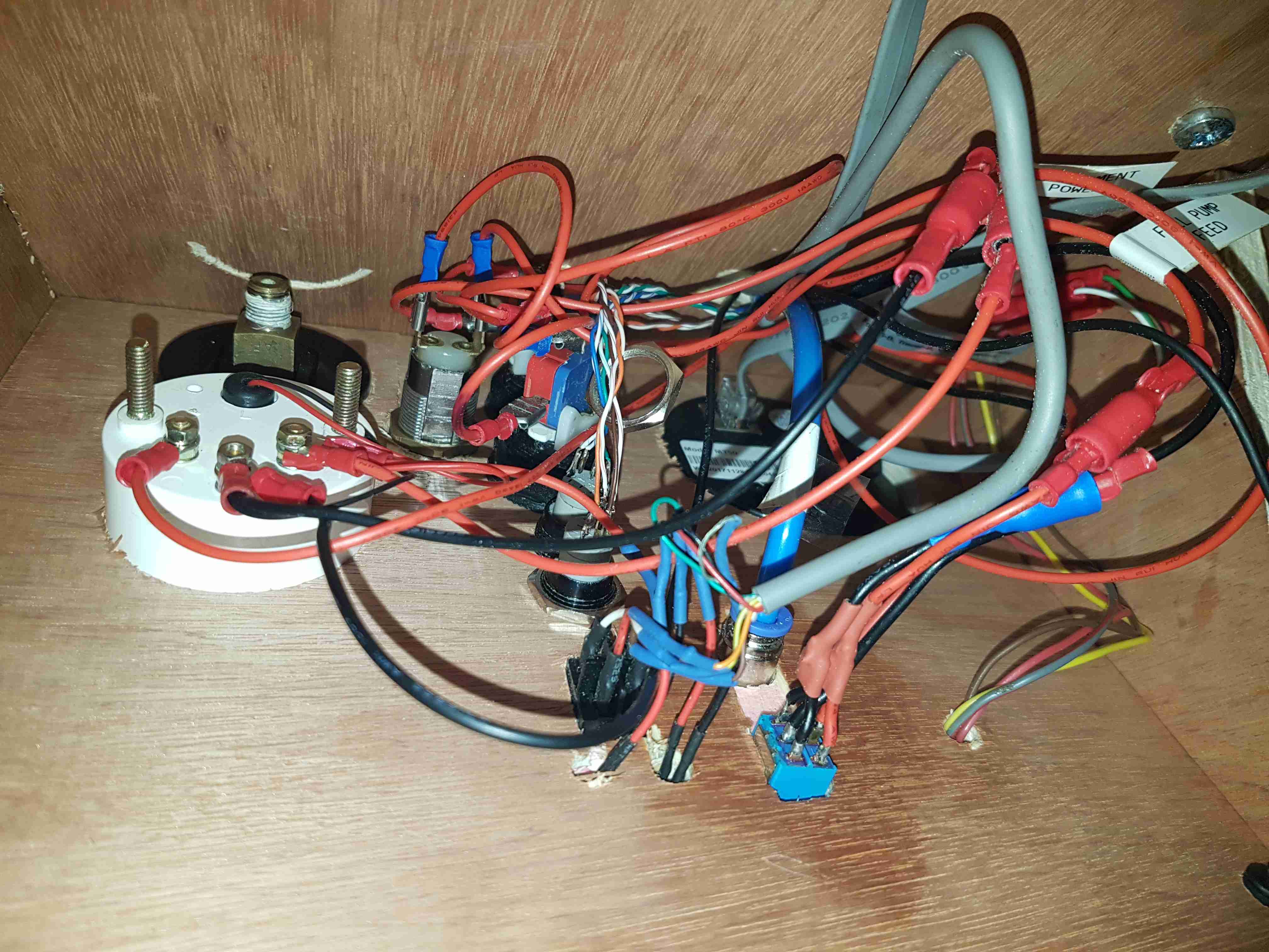
Panel Wiring
As is usual behind instrument panels, there’s a rat’s nest of wiring. There’s still the pressure gauge to connect up for the compressed air system, and the nut on one of the router buttons is such a tight fit I’ve not managed to get it into place yet.
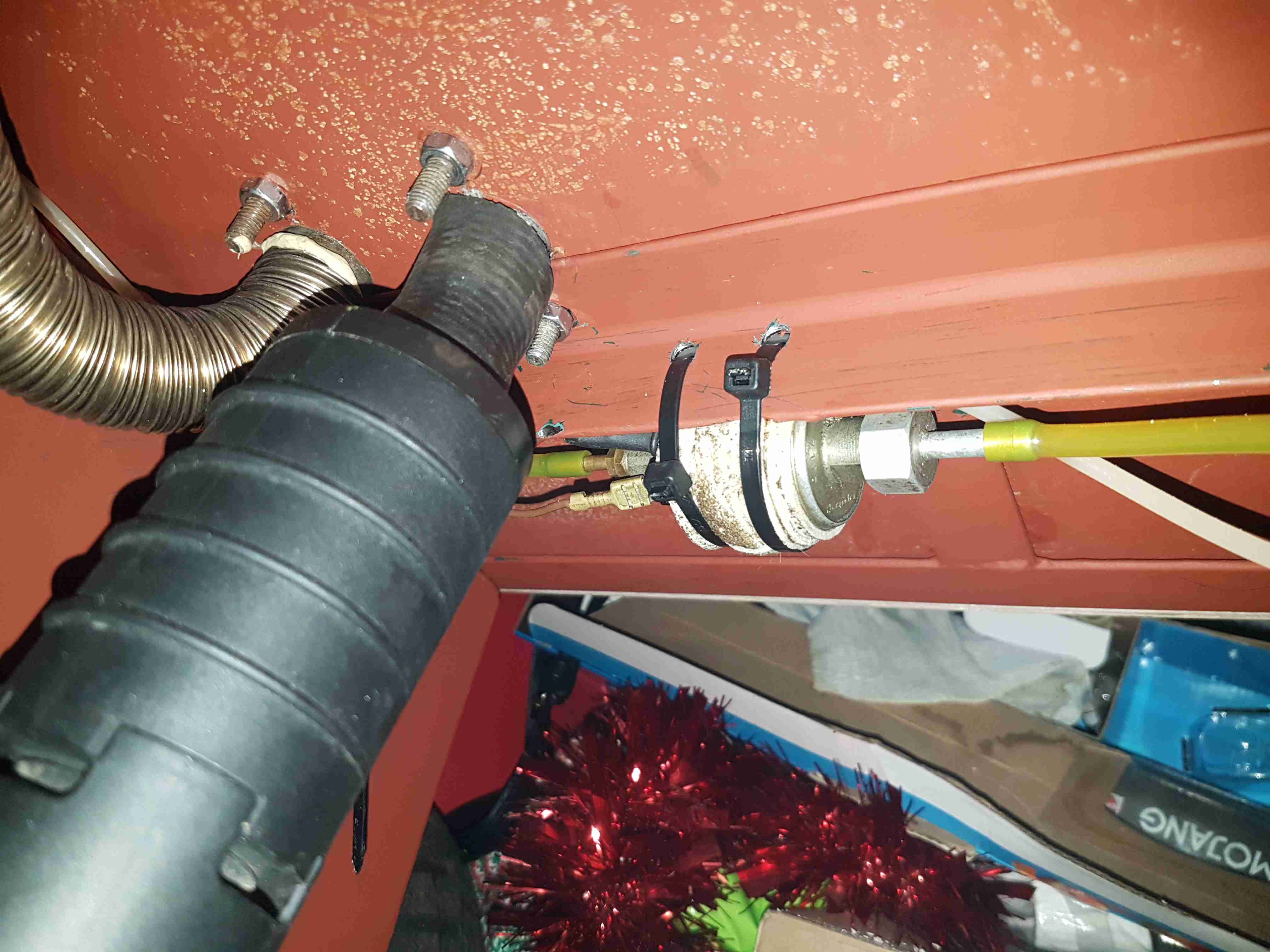
Eberspacher Fuel Pump
The support components for the Eberspacher heater are mounted underneath the baseplate, with the fuel dosing pump secured to a rail with a pair of cable ties, and some foam tape around to isolate the constant clicking noise these pumps create in operation. The large black cylinder is the combustion air intake silencer, with the stainless steel exhaust pipe to the left of that. Silencing these heaters is essential – they sound like a jet engine without anything to deaden the noise. Most of this is generated from the side-channel blower used in the burner.
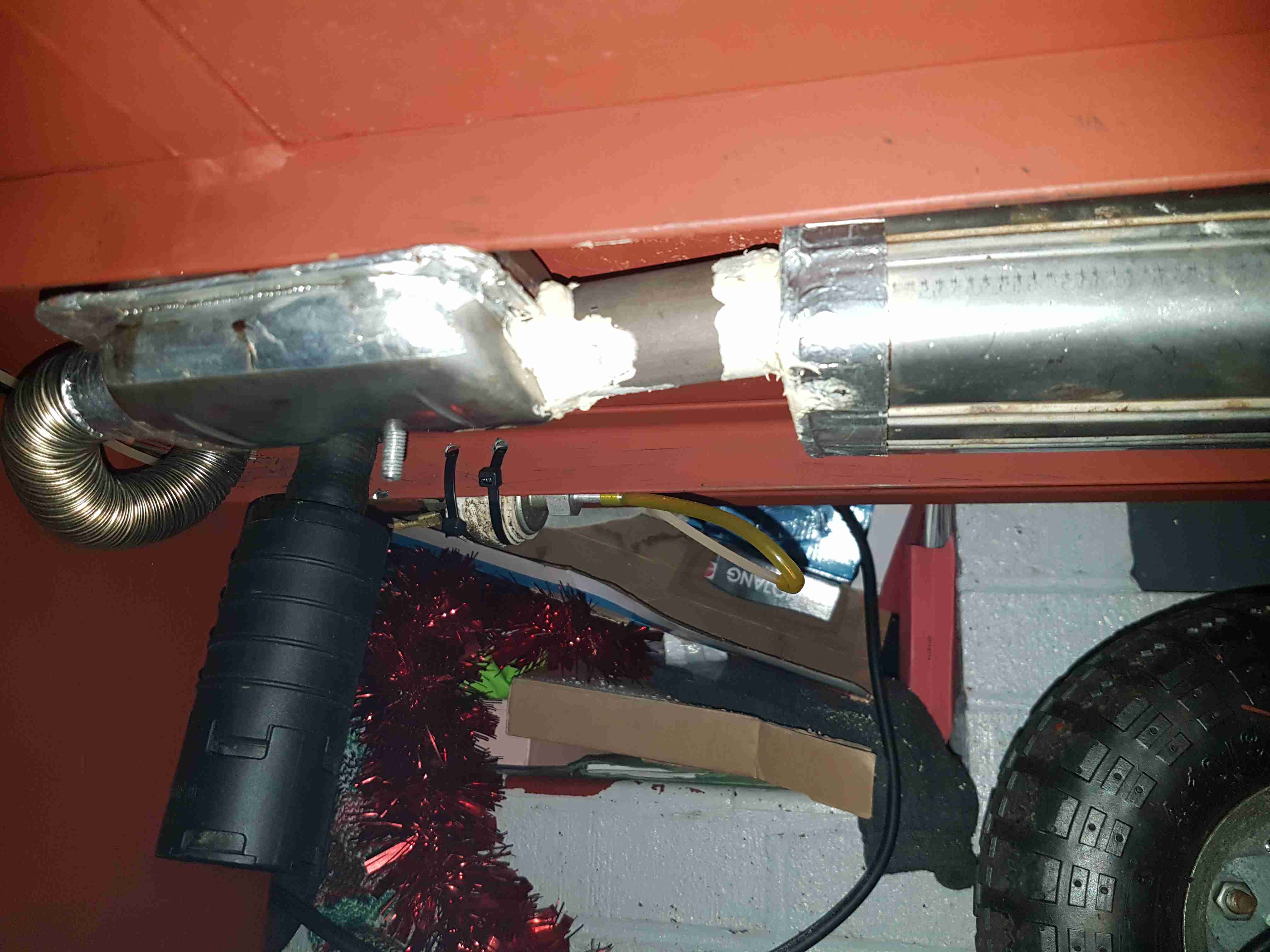
Eberspacher Exhaust
Bolted to the underside are a pair of exhaust silencers, one is an Eberspacher brand, the other is Webasto, since the latter type are better at reducing the exhaust noise. Connections are sealed with commerical exhaust assembly paste, the usual clamps supplied do not do a good enough job of stopping exhaust leaks.
Next update to come when I get the parts in for the air compressor system.
The Sterling charger we’ve had on board nb Tanya Louise since Feb 2014 has bitten the dust, with 31220 hours on it’s internal clock. Since we’re a liveaboard boat, this charger has had a lot of use while we’re on the mooring during winter, when the solar bank isn’t outputting it’s full rate. First, a bit of a teardown to explore the unit, then onto the repair:
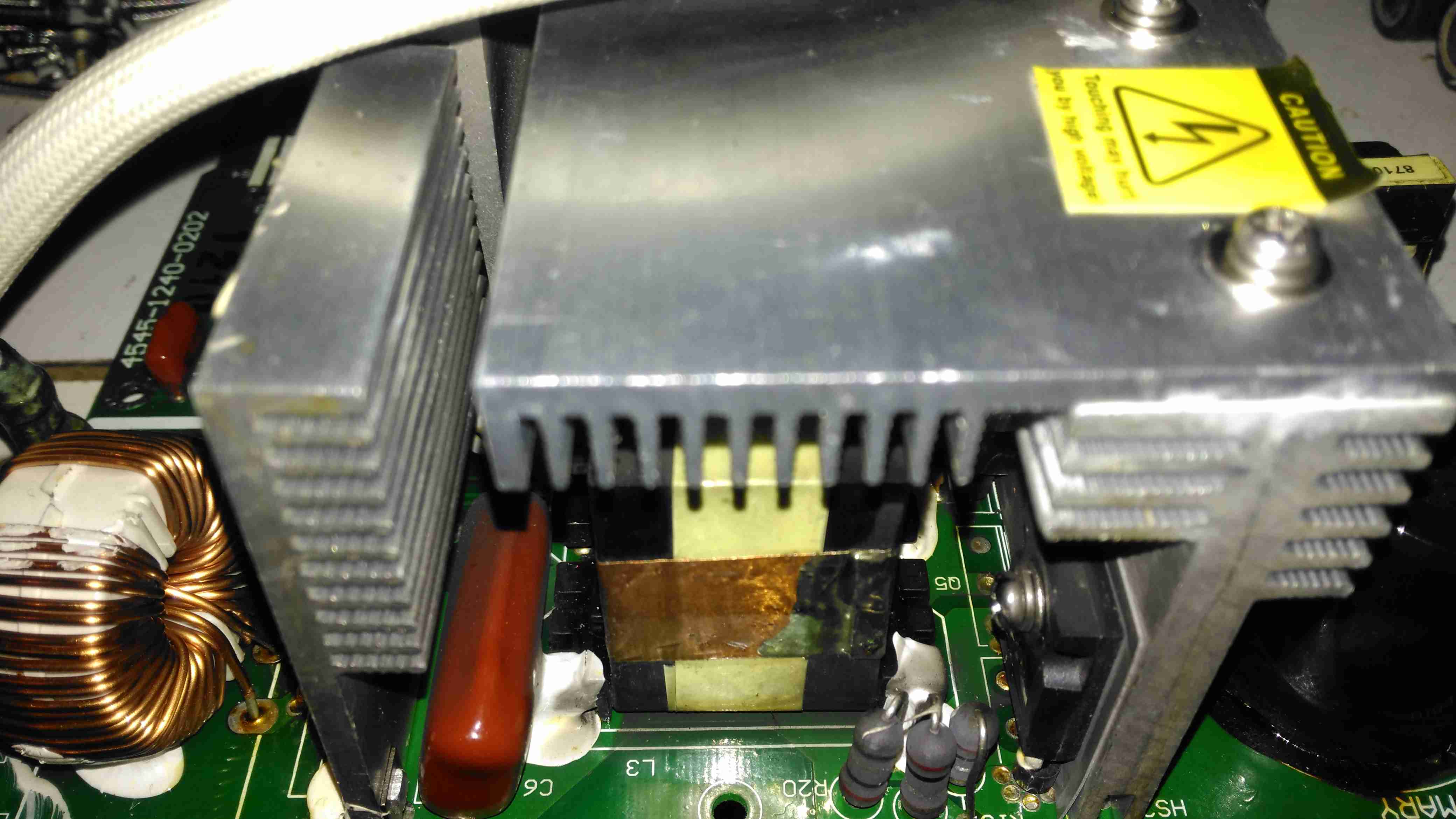
Active PFC Section
There’s the usual mains input filtering on the left, with the bridge rectifier on it’s heatsink.
Underneath the centre massive heatsinks is the main transformer (not visible here) & active PFC circuit. The device peeking out from underneath is the huge inductor needed for PFC. It’s associated switching MOSFET is to the right.
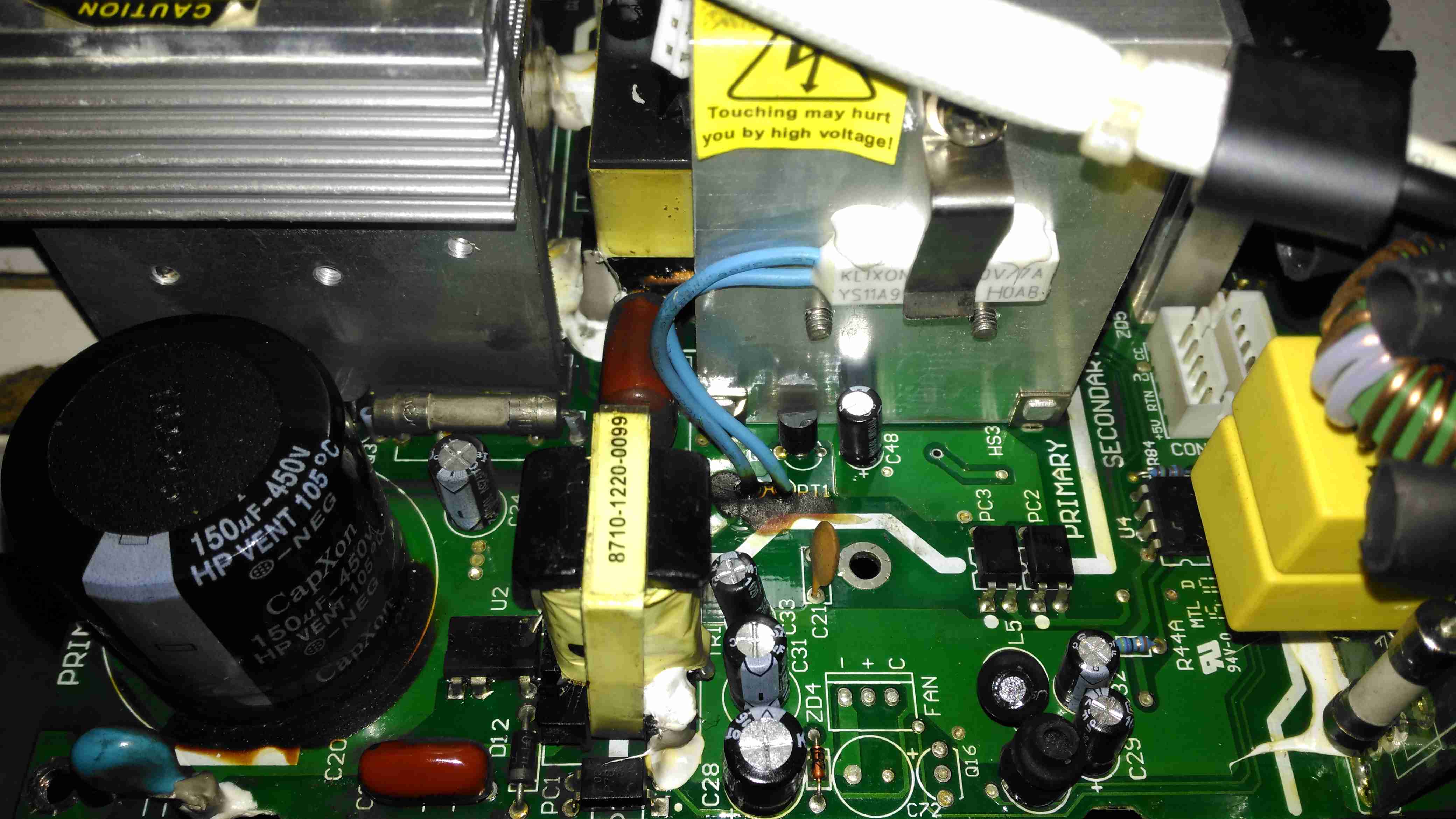
Logic PSU Section
On the other side of the PFC section is the main DC rail filter electrolytic, a 450v 150µF part. Here some evidence of long-term heating can be seen in the adhesive around the base, it’s nearly completely turned black! It’s not a decent brand either, a Chinese CapXon.
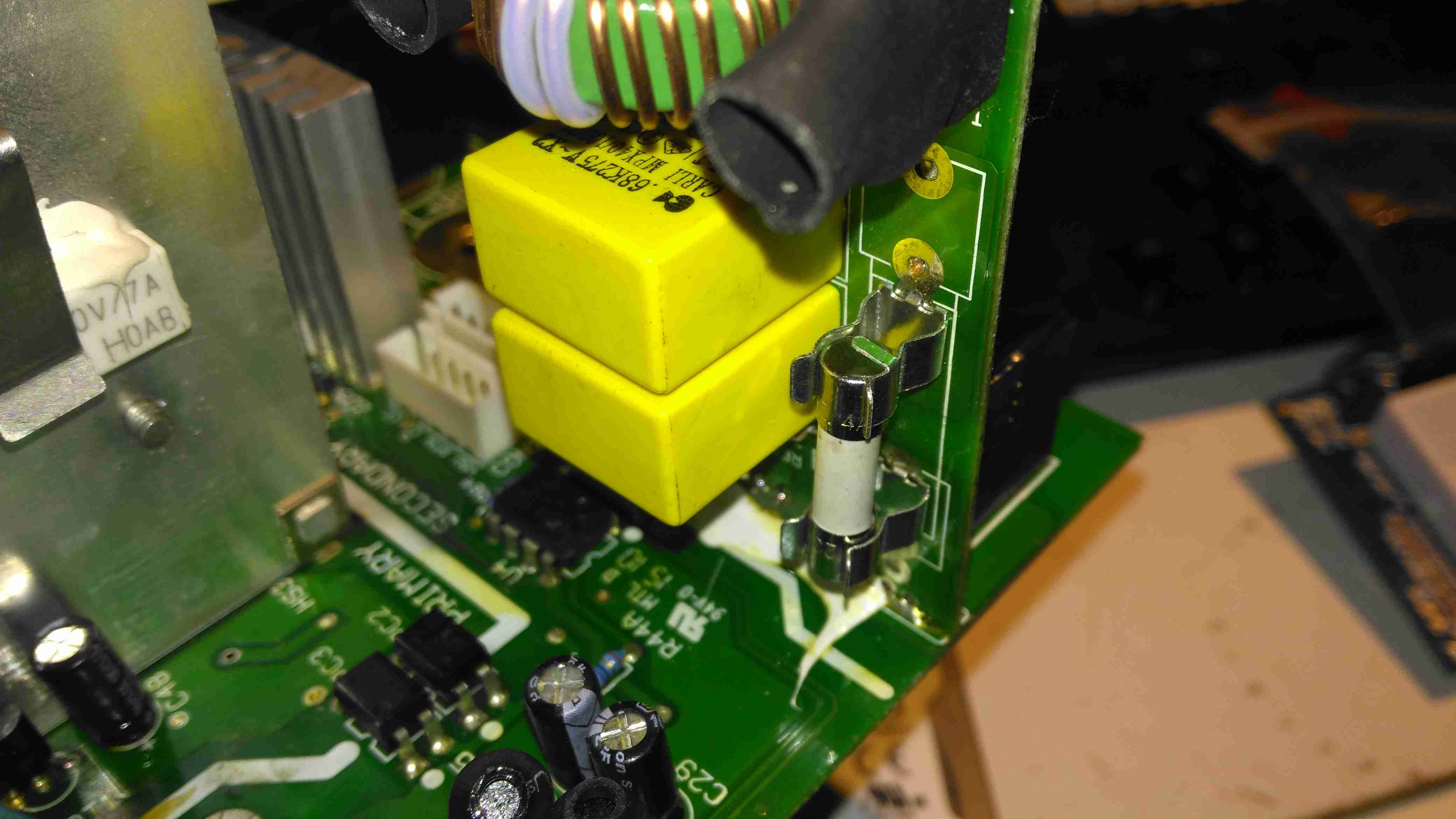
The PCB fuse just behind it is in the DC feed to the main switching supply, so the input fuse only protects the filter & Active PFC circuitry. Luckily this fuse didn’t blow during the failure, telling me the fault was earlier in the power chain.
The logic circuits are powered by an independent switching supply in the centre, providing a +5v rail to the microcontroller. The fan header & control components are not populated in this 10A model, but I may end up retrofitting a fan anyway as this unit has always run a little too warm. The entire board is heavily conformal coated on both sides, to help with water resistance associated with being in a marine environment. This has worked well, as there isn’t a single trace of moisture anywhere, only dust from years of use.
There is some thermal protection for the main SMPS switching MOSFETS with the Klixon thermal fuse clipped to the heatsink.
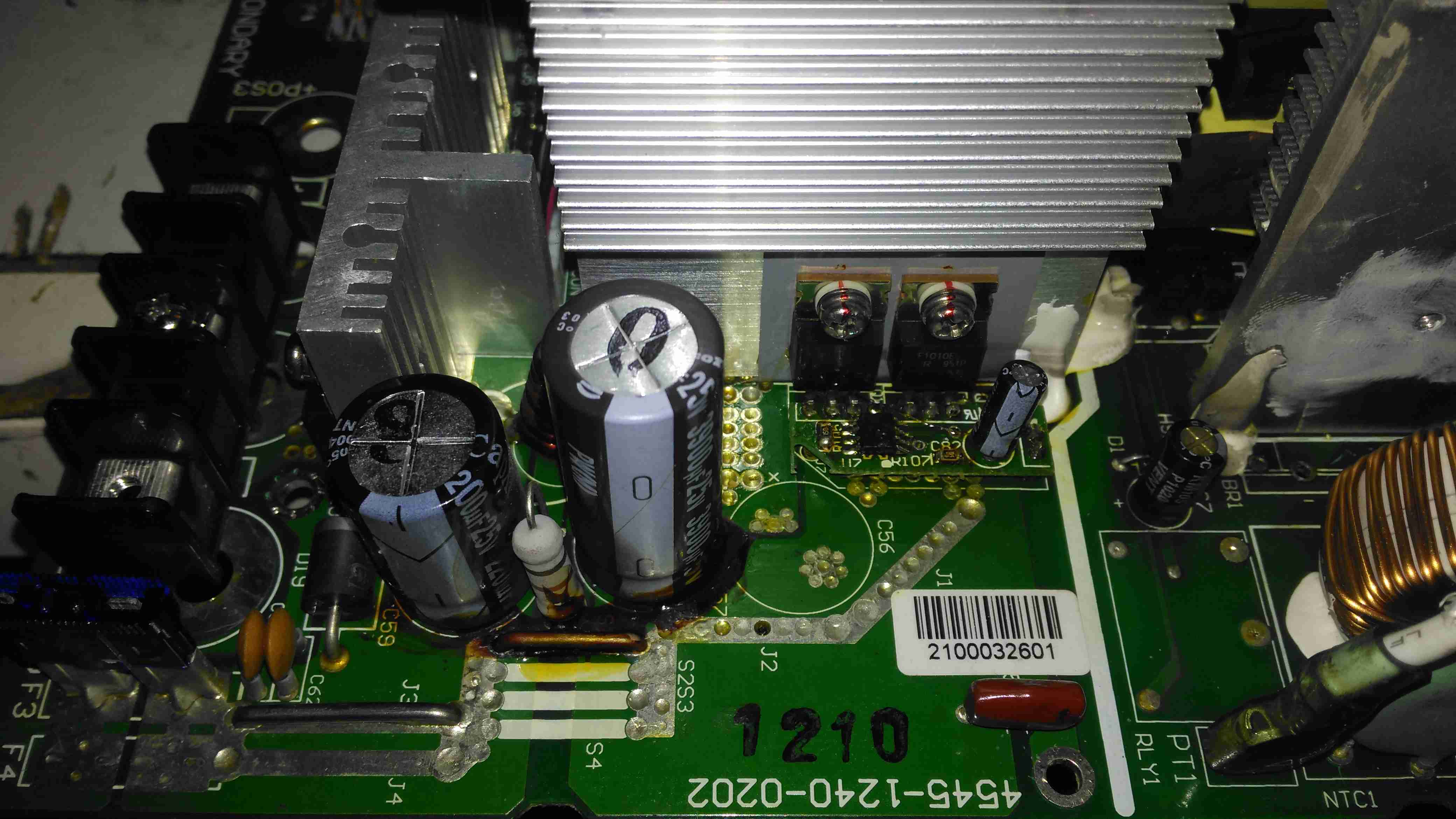
DC Output Section
The DC output rectifiers are on the large heatsink in the centre, with a small bodge board fitted. Due to the heavy conformal coating on the board I can’t get the ID from this small 8-pin IC, but from the fact that the output rectifiers are in fact IRF1010E MOSFETS, rated at 84A a piece, this is an synchronous rectifier controller.
Oddly, the output filter electrolytics are a mix of Nichicon (nice), and CapXon (shite). A bit of penny pinching here, which if a little naff since these chargers are anything but cheap. (£244.80 at the time of writing).
Hiding just behind the electrolytics is a large choke, and a reverse-polarity protection diode, which is wired crowbar-style. Reversing the polarity here will blow the 15A DC bus fuse instantly, and may destroy this diode if it doesn’t blow quick enough.
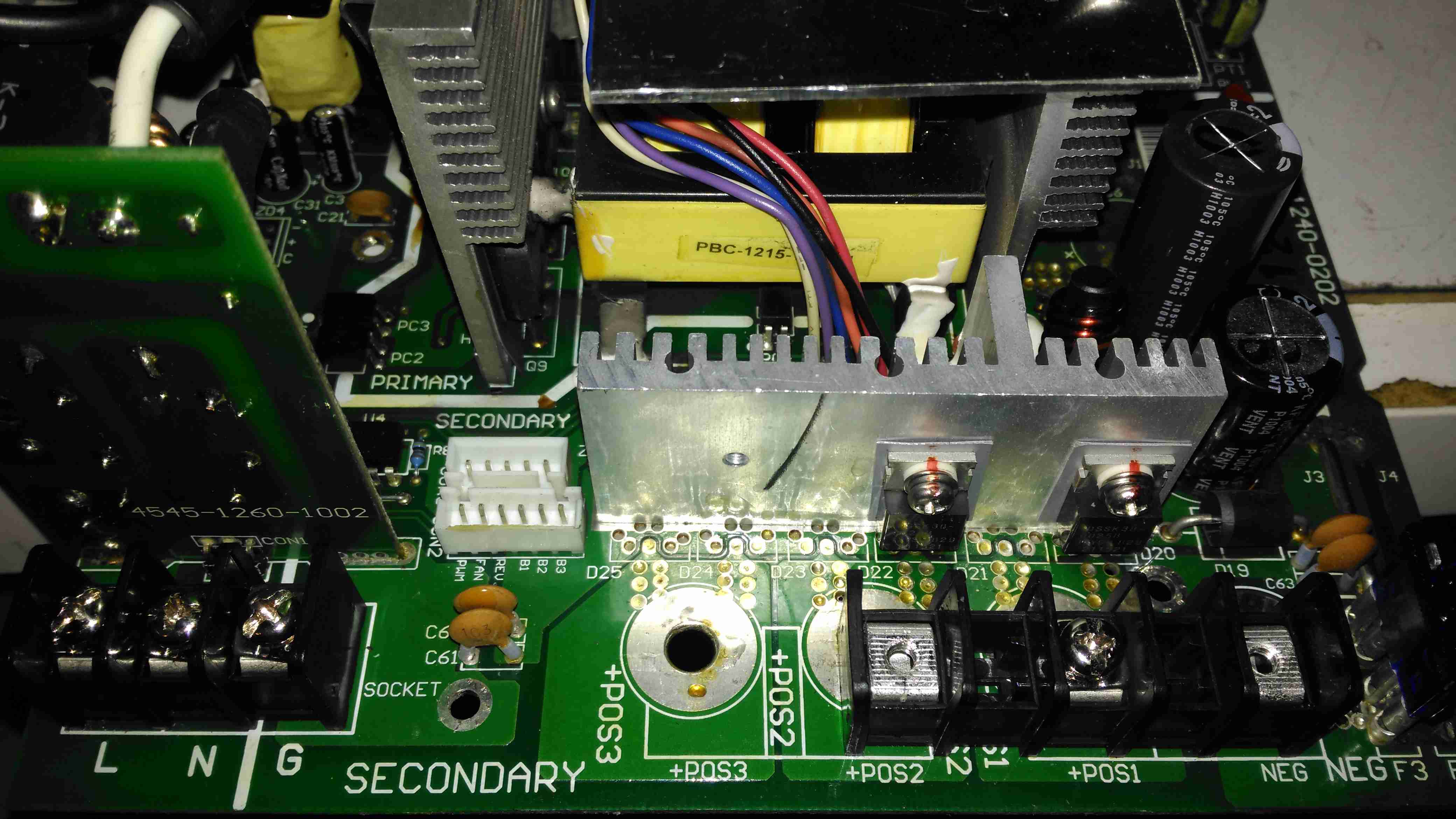
DC Outputs
Right on the output end are a pair of large Ixys DSSK38 TO220 Dual 20A dual Schottky diodes, isolating the two outputs from each other, a nice margin on these for a 10A charger, since the diodes are paralleled each channel is capable of 40A. This prevents one bank discharging into another & allows the charger logic to monitor the voltages individually. The only issue here is the 400mV drop of these diodes introduce a little bit of inefficiency. To increase current capacity of the PCB, the aluminium heatsink is being used as the main positive busbar. From the sizing of the power components here, I would think that the same PCB & component load is used for all the chargers up to 40A, since both the PFC inductor & main power transformer are massive for a 10A output. There are unpopulated output components on this low-end model, to reduce the cost since they aren’t needed.
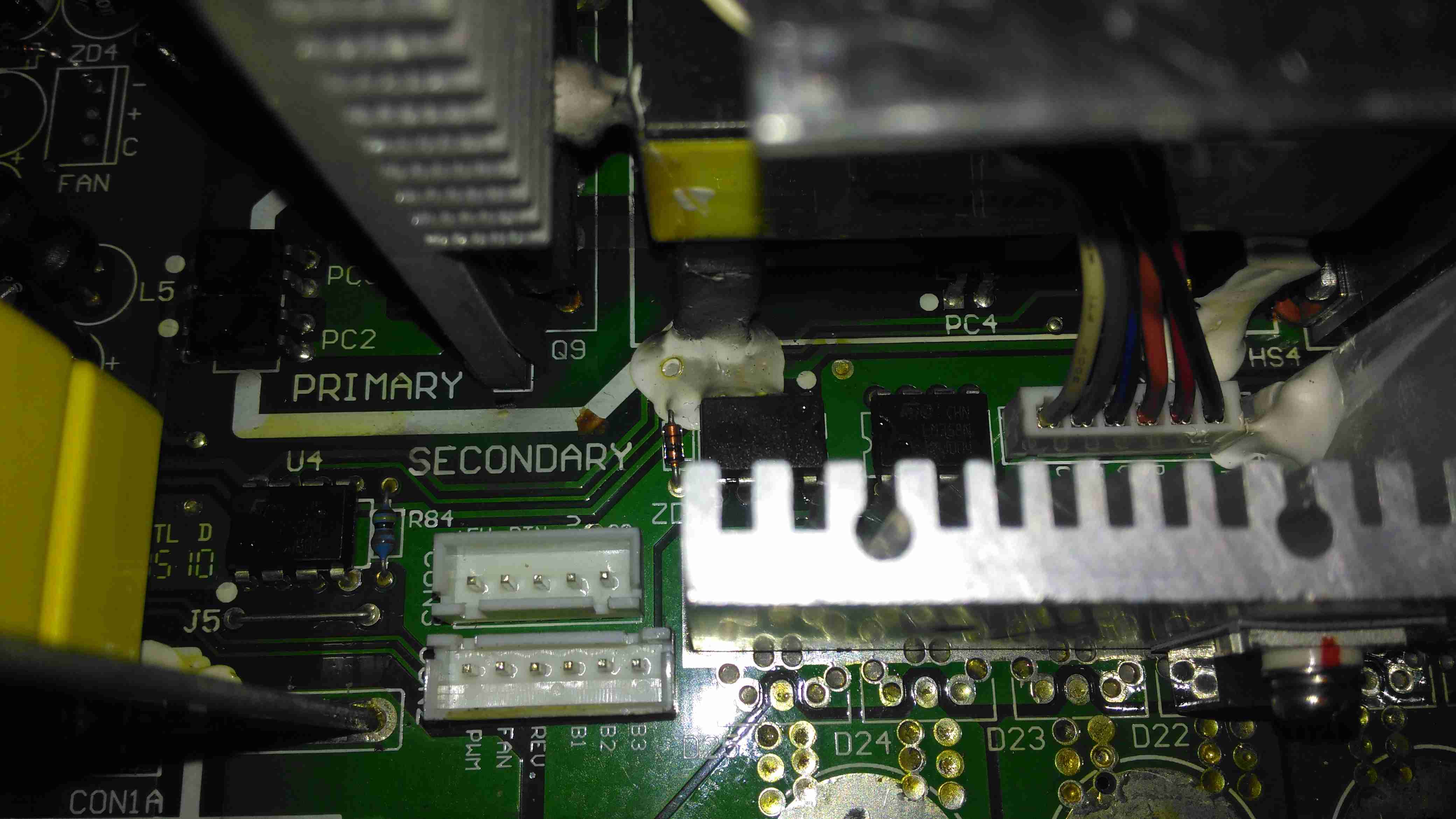
Front Panel Control Connections
A trio of headers connect all the control & sense signals to the front panel PCB, which contains all the control logic. This unit is sensing all output voltages, output current & PSU rail voltages.
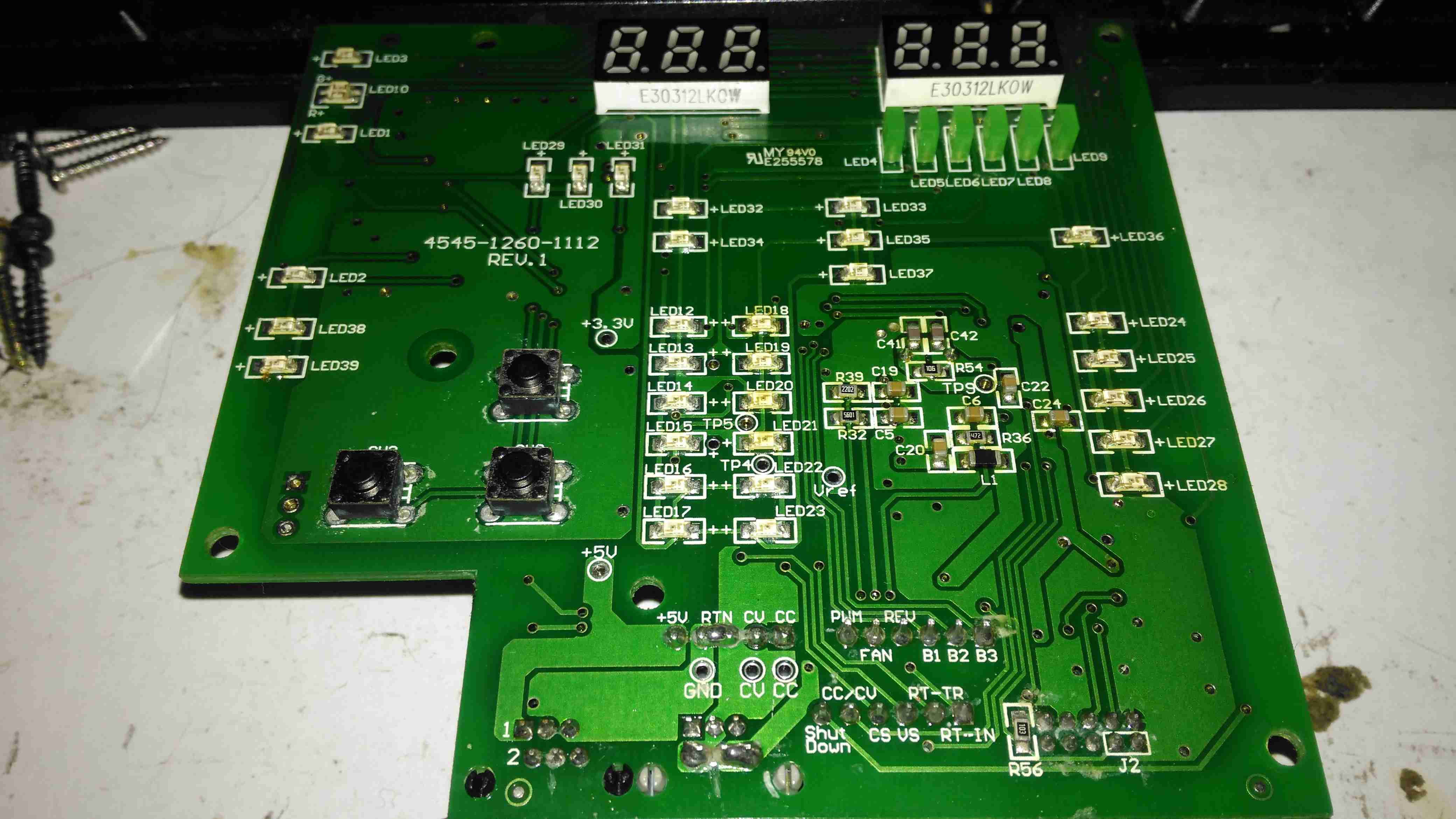
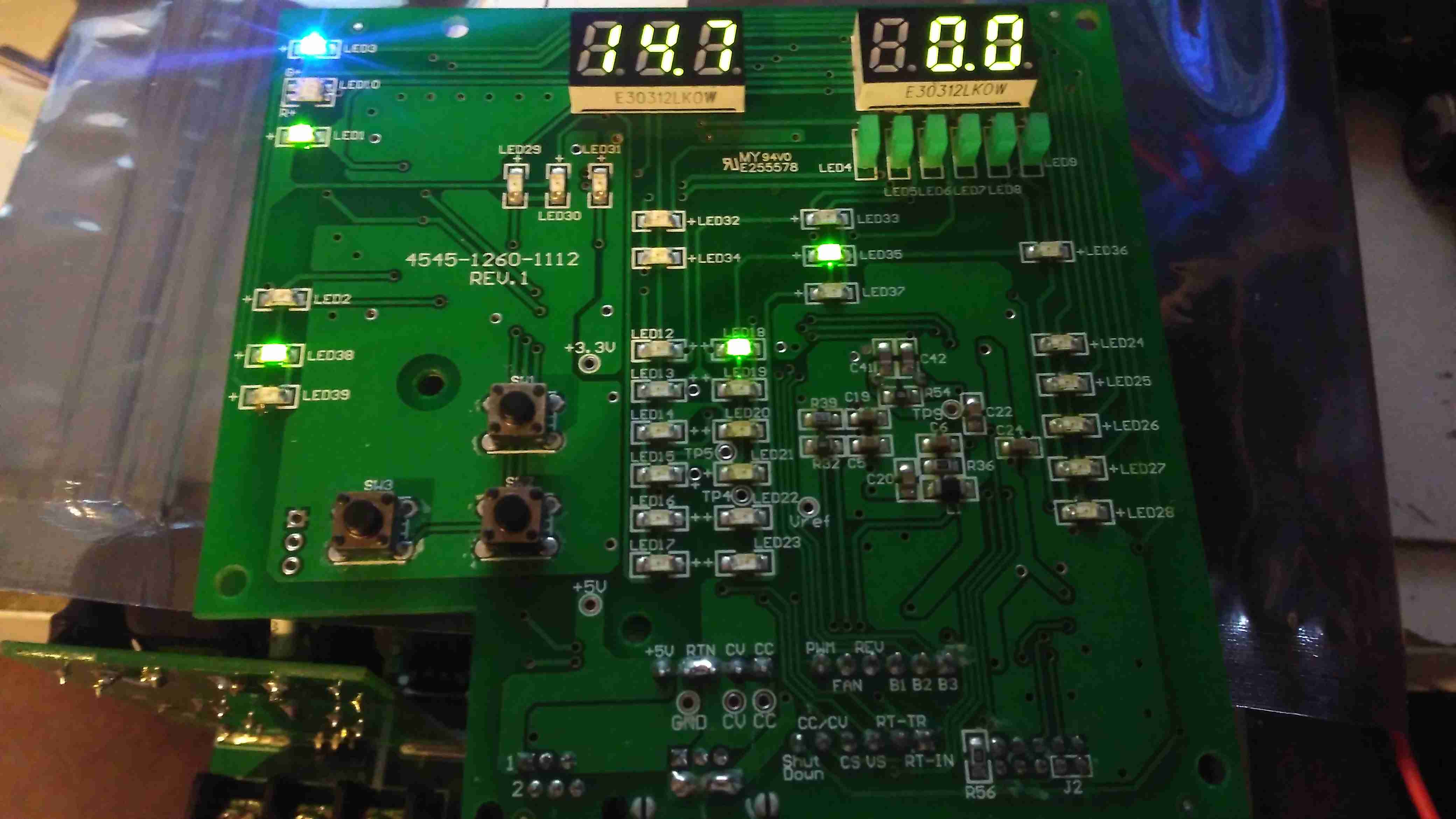
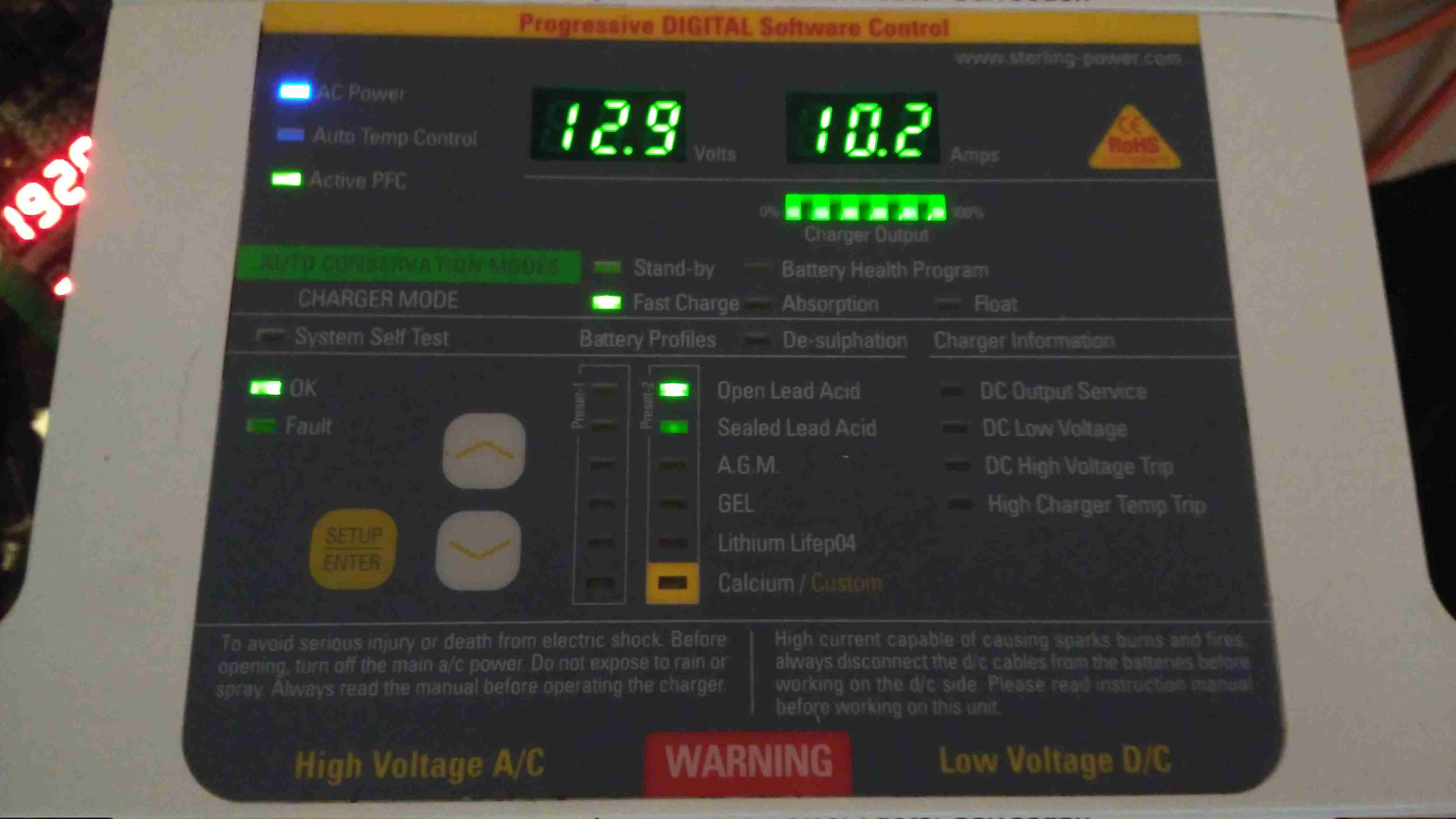
Front Panel LEDs
The front panel is stuffed with LEDs & 7-segment displays to show the current mode, charging voltage & current. There’s 2 tactile switches for adjustments.
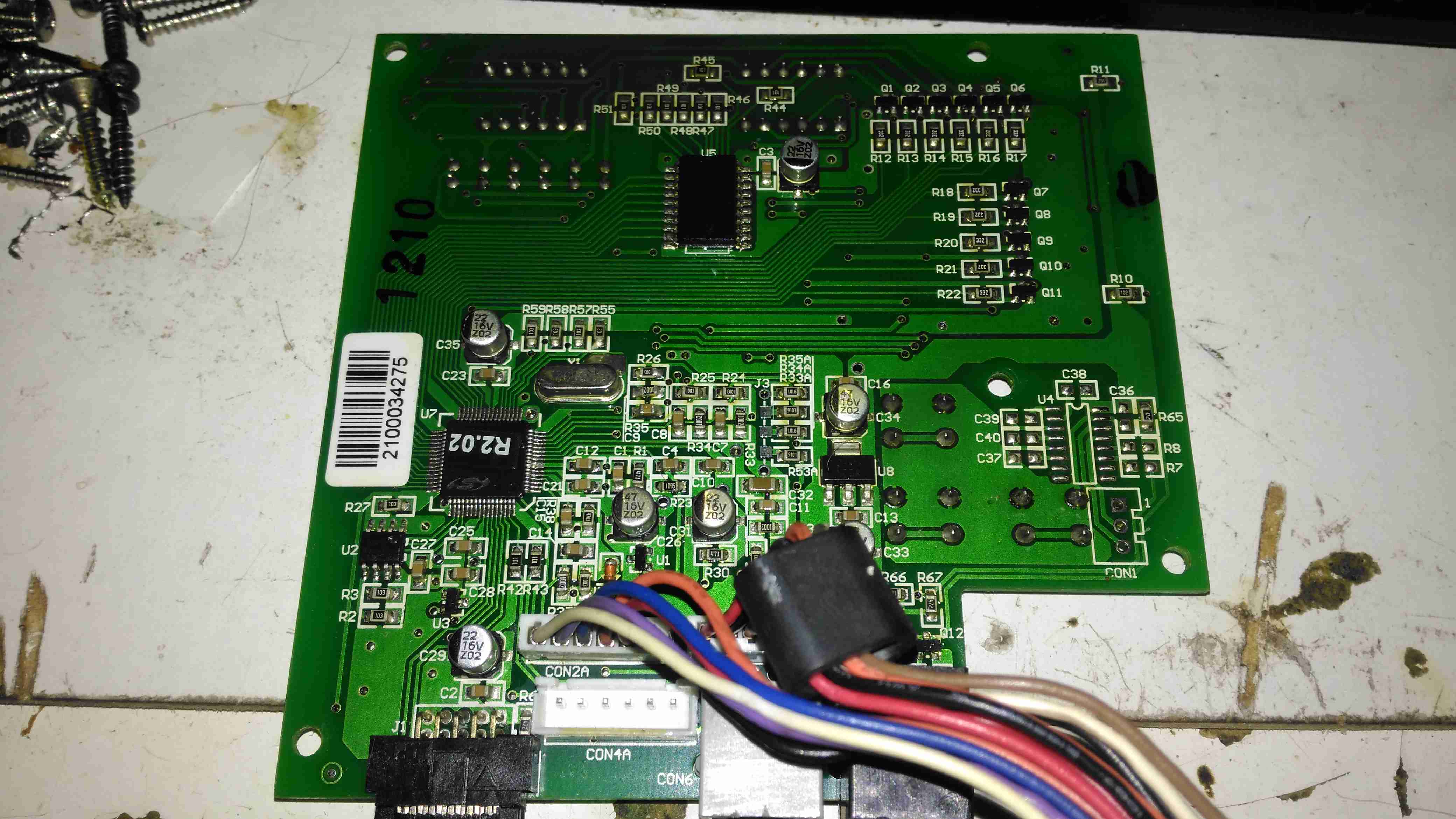
Front Panel Reverse
The reverse of the board has the main microcontroller – again identifying this is impossible due to the heavy conformal coat. The LEDs are being driven through a 74HC245D CMOS Octal Bus Transceiver.
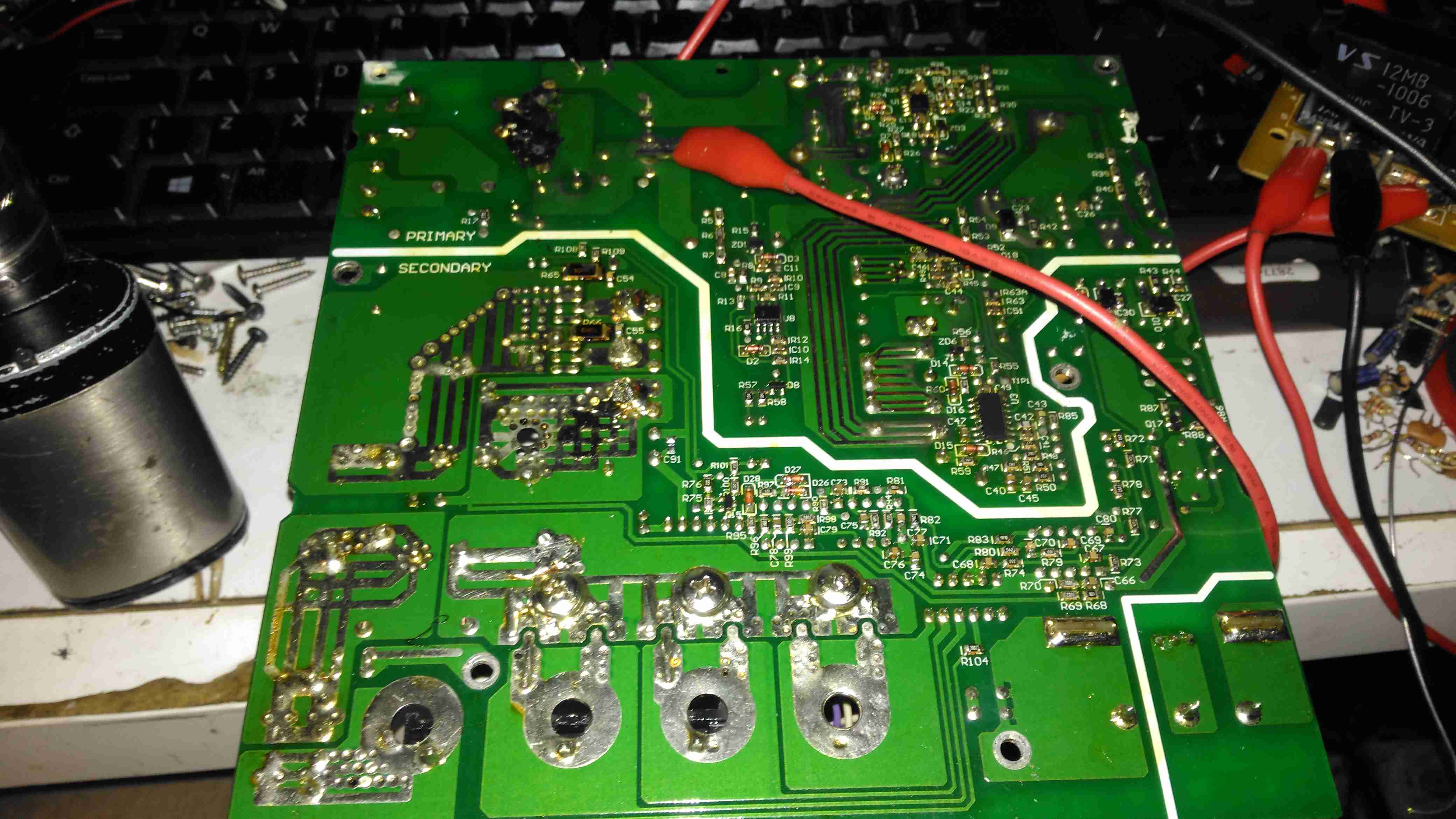
Now on to the repair! I’m not particularly impressed with only getting 4 years from this unit, they are very expensive as already mentioned, so I would expect a longer lifespan. The input fuse had blown in this case, leaving me with a totally dead charger. A quick multimeter test on the input stage of the unit showed a dead short – the main AC input bridge rectifier has gone short circuit.
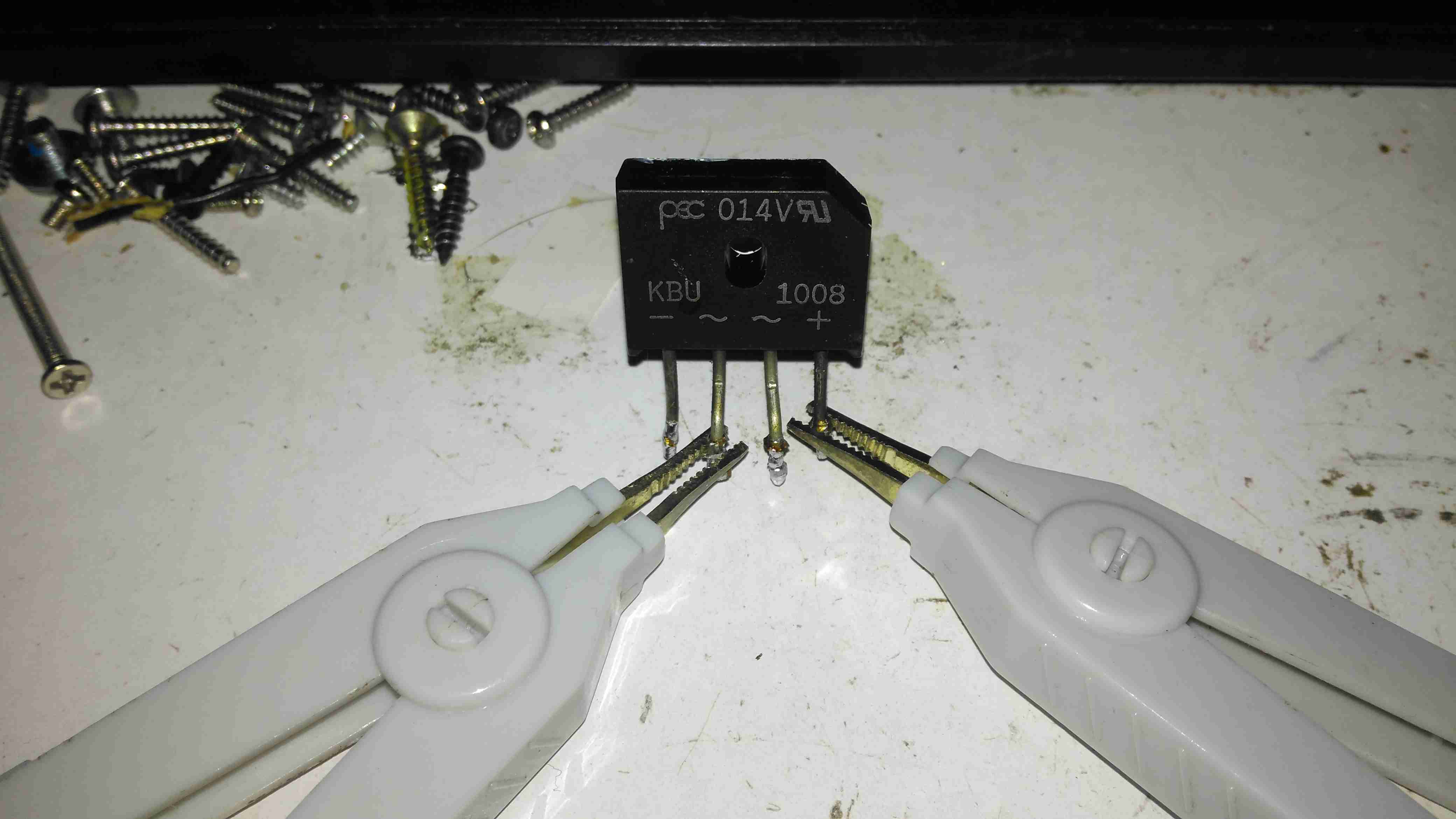
Bridge Rectifier Removed
Here the defective bridge has been desoldered from the board. It’s a KBU1008 10A 800v part. Once this was removed I confirmed there was no longer an input short, on either the AC side or the DC output side to the PFC circuit.
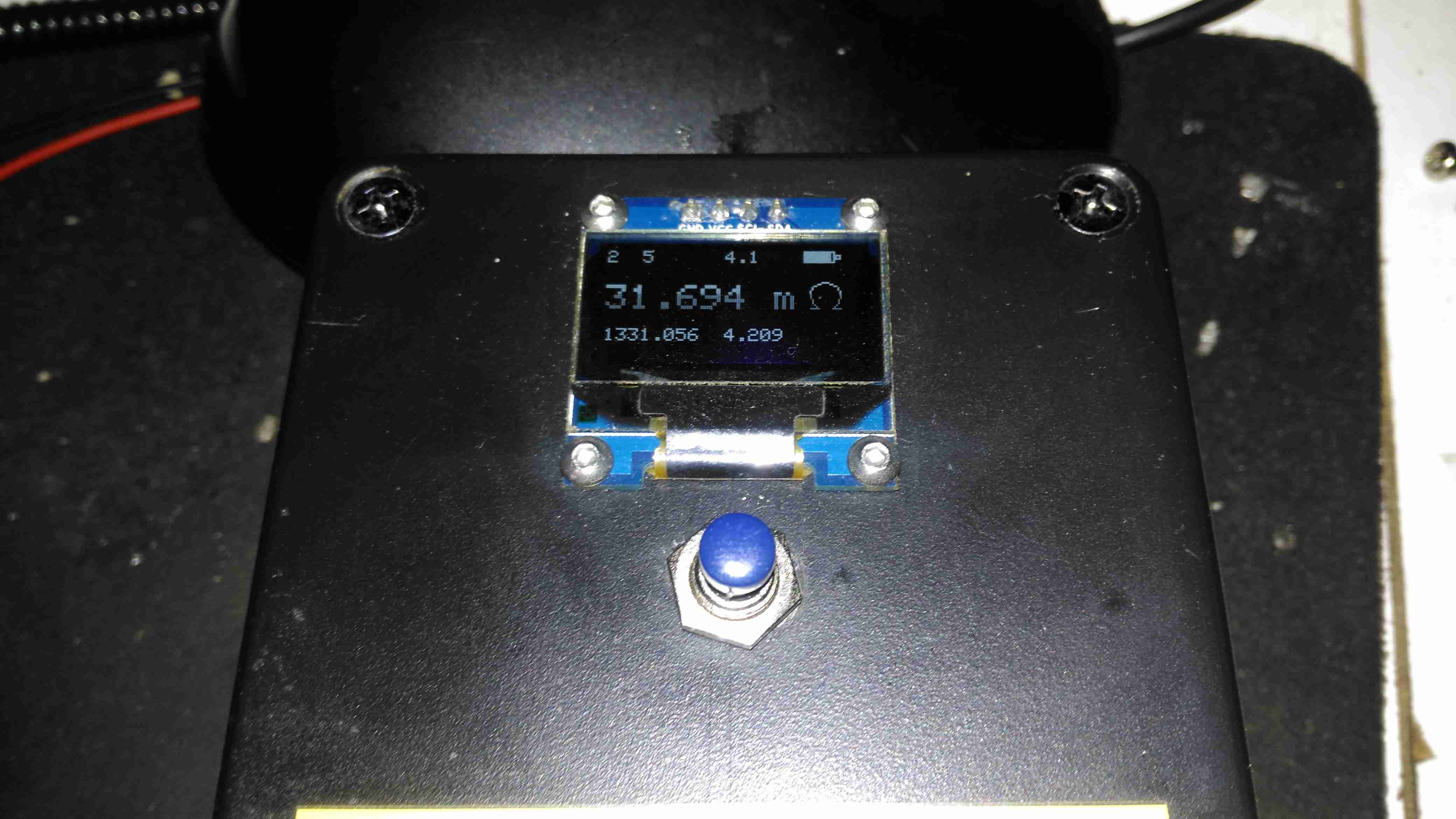
Testing The Rectifier
Time to stick the desoldered bridge on the milliohm meter & see how badly it has failed.
Yep, Definitely Shorted
I’d say 31mΩ would qualify as a short. It’s no wonder the 4A input fuse blew instantly. There is no sign of excessive heat around the rectifier, so I’m not sure why this would have failed, it’s certainly over-rated for the 10A charger.
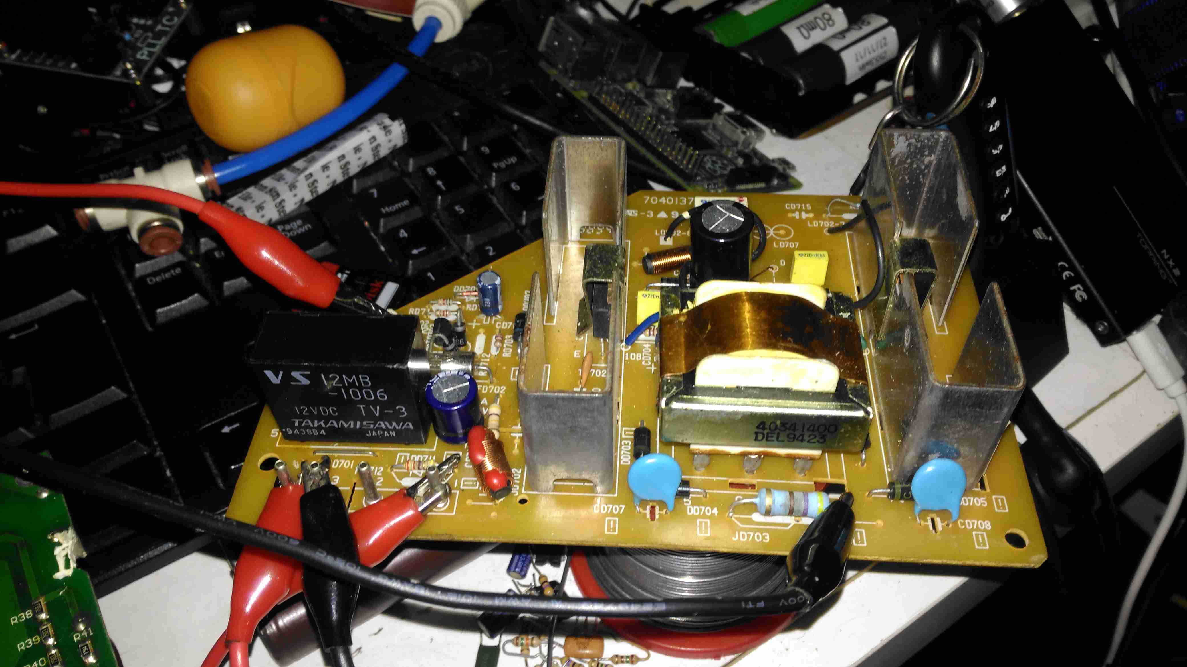
Testing Without Rectifier
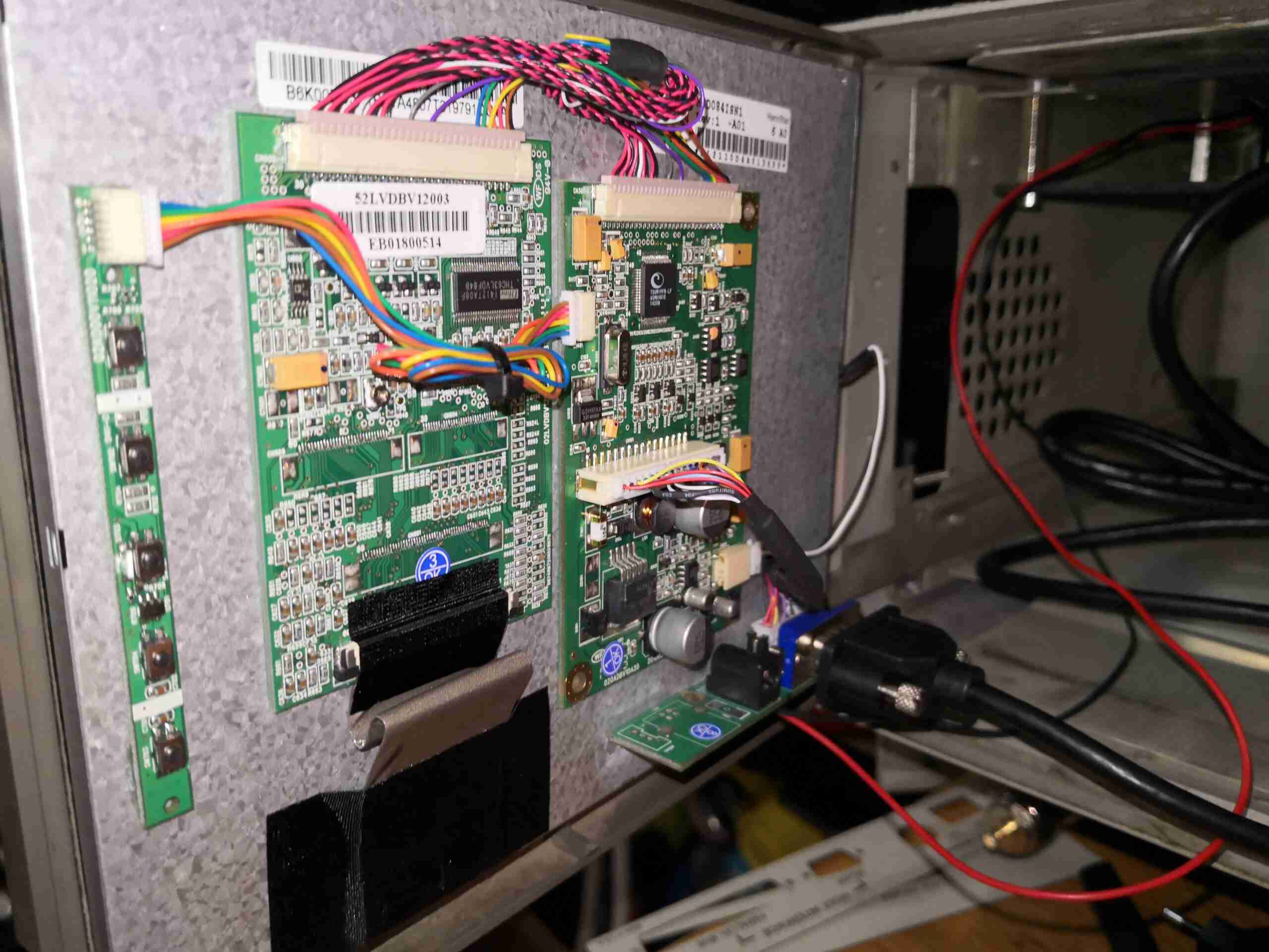
Now the defective diode bridge has been removed from the circuit, it’s time to apply some controlled power to see if anything else has failed. For this I used a module from one of my previous teardowns – the inverter from a portable TV.
Test Inverter
This neat little unit outputs 330v DC at a few dozen watts, plenty enough to power up the charger with a small load for testing purposes. The charger does pull the voltage of this converter down significantly, to about 100v, but it still provides just enough to get things going.
It’s Alive!
After applying some direct DC power to the input, it’s ALIVE! Certainly makes a change from the usual SMPS failures I come across, where a single component causes a chain reaction that writes off everything.
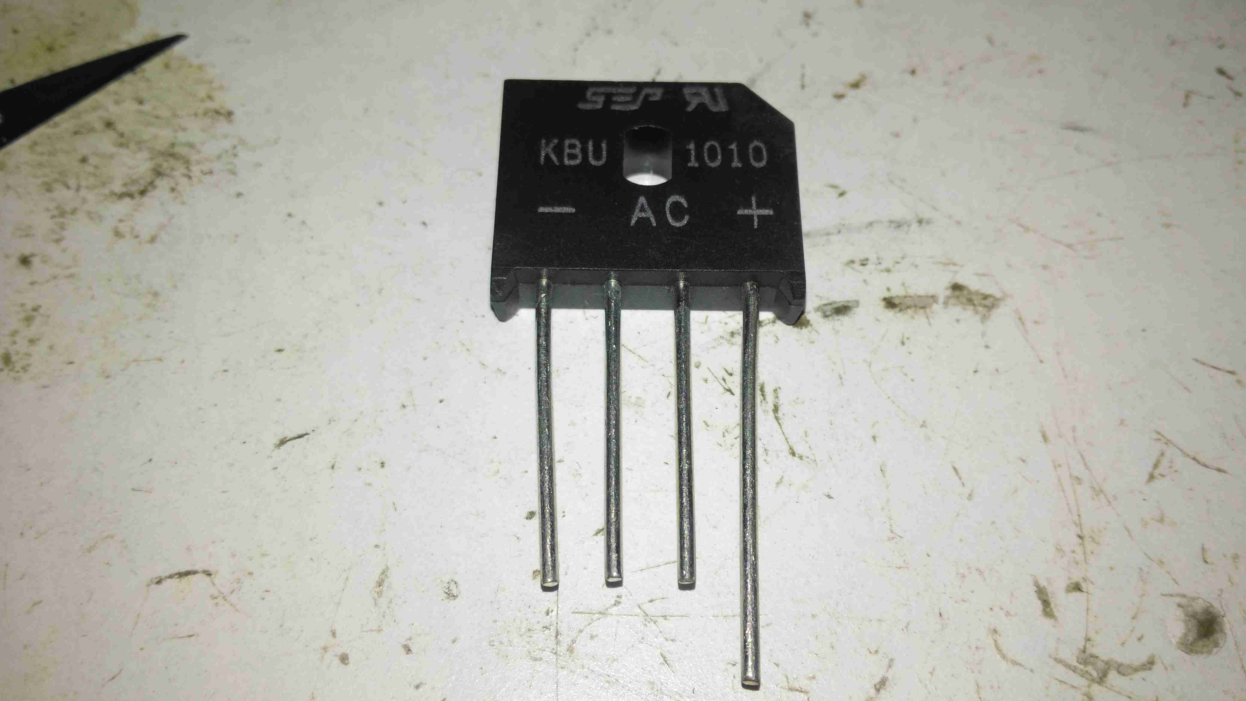
Replacement Rectifier
Unfortunately I couldn’t find the exact same rectifier to replace the shorted one, so I had to go for the KBU1010, which is rated for 1000v instead of 800v, but the Vf rating (Forward Voltage), is the same, so it won’t dissipate any more power.
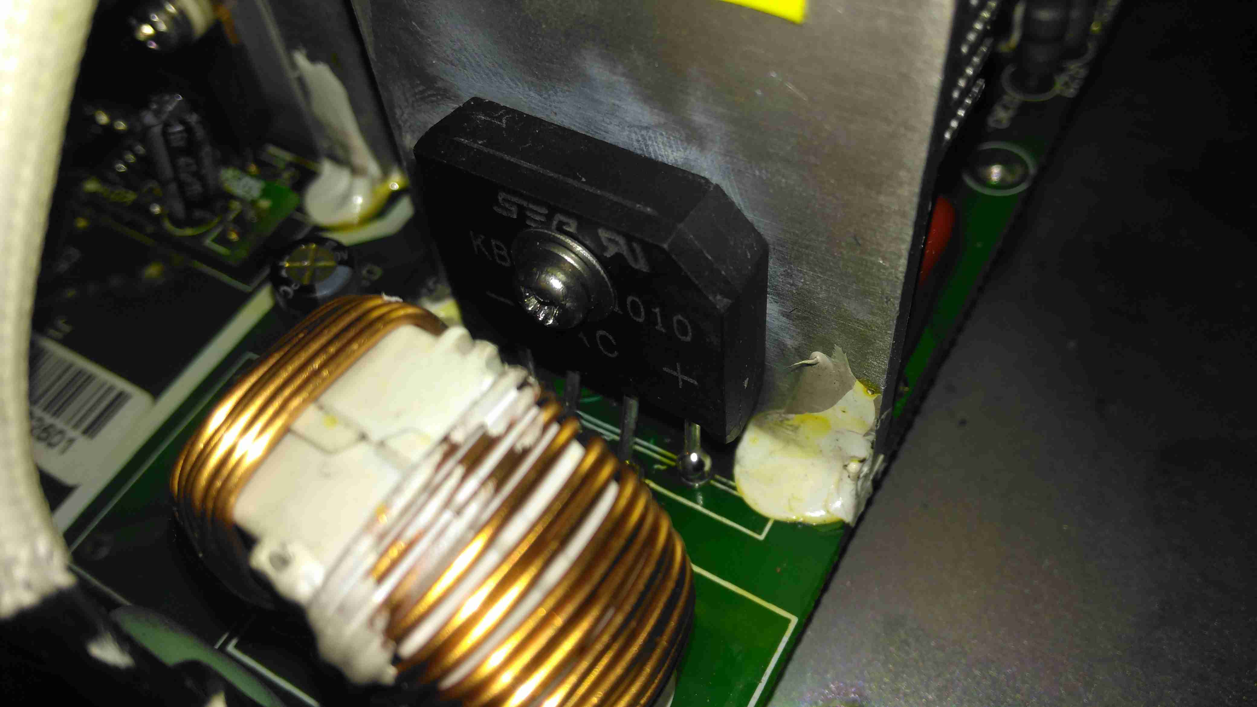
Soldered In
Here’s the new rectifier soldered into place on the PCB & bolted to it’s heatsink, with some decent thermal compound in between.
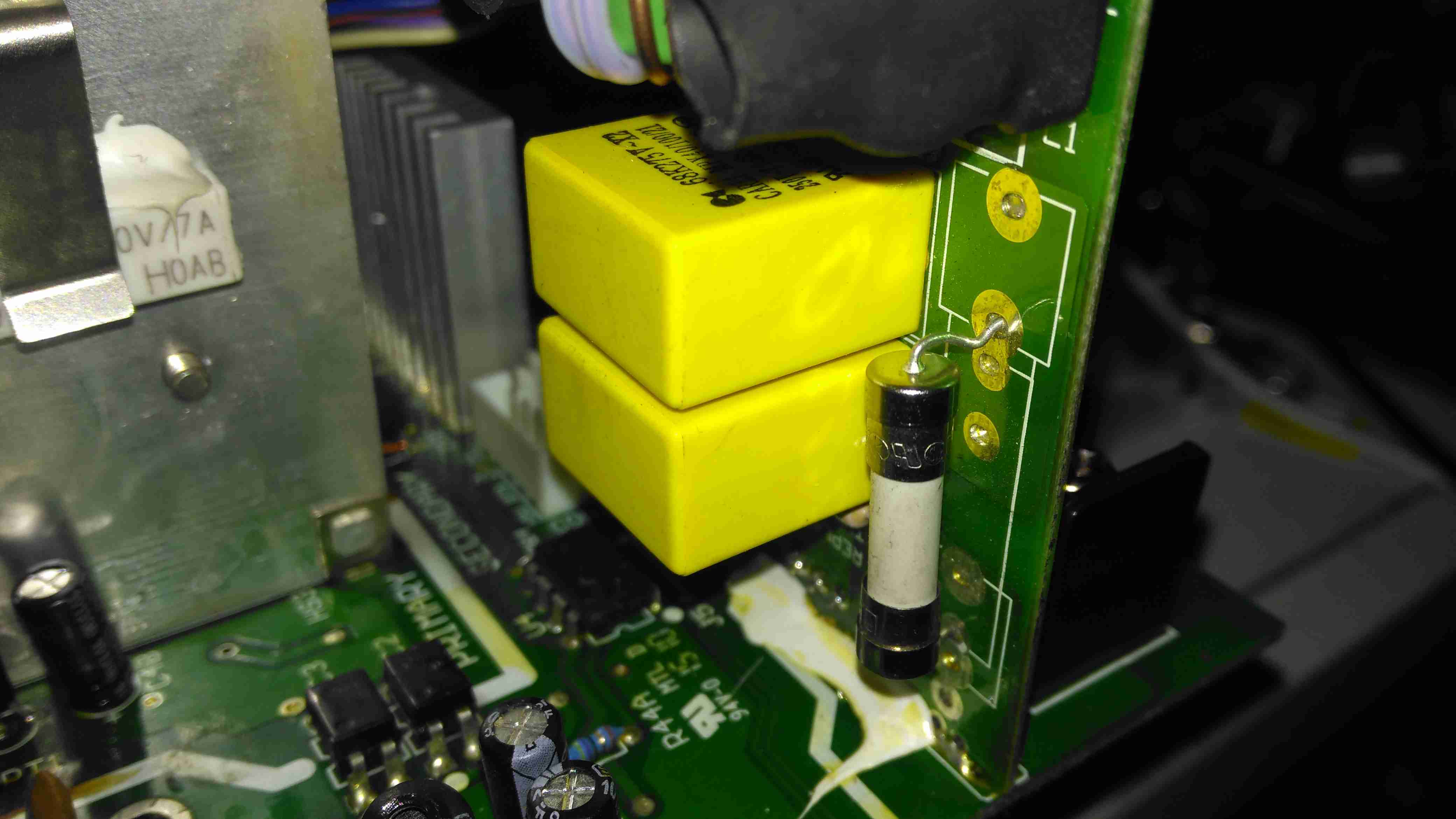
Input Board
Here is the factory fuse, a soldered in device. I’ll be replacing this with standard clips for 20x5mm fuses to make replacement in the future easier, the required hole pattern in the PCB is already present. Most of the mains input filtering is also on this little daughterboard.
Fuse Replaced
Now the fuse has been replaced with a standard one, which is much more easily replaceable. This fuse shouldn’t blow however, unless another fault develops.
Full Load Test
Now everything is back together, a full load test charging a 200Ah 12v battery for a few hours will tell me if the fix is good. This charger won’t be going back into service onboard the boat, it’s being replaced anyway with a new 50A charger, to better suit the larger loads we have now. It won’t be a Sterling though, as they are far too expensive. I’ll report back if anything fails!
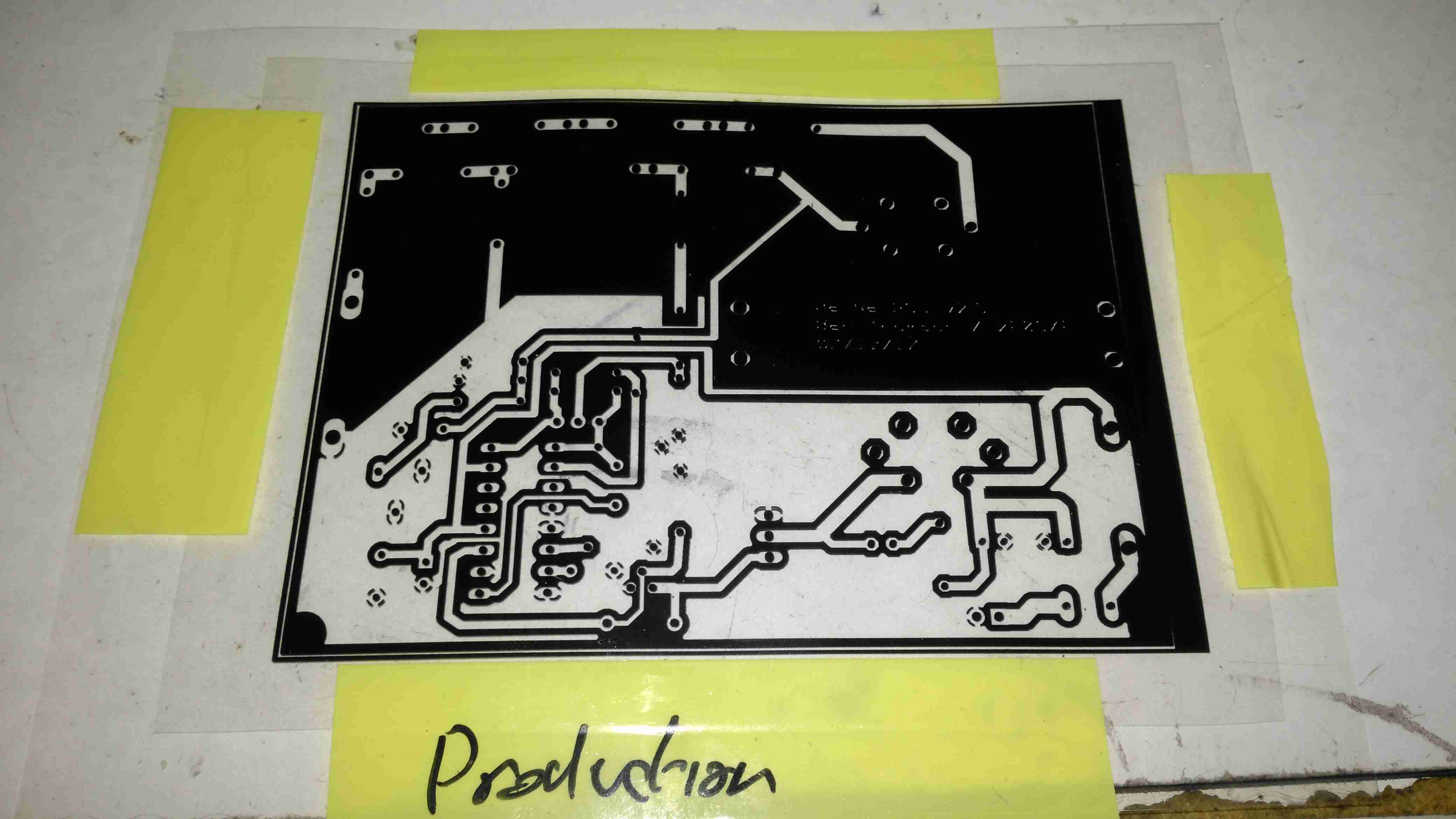
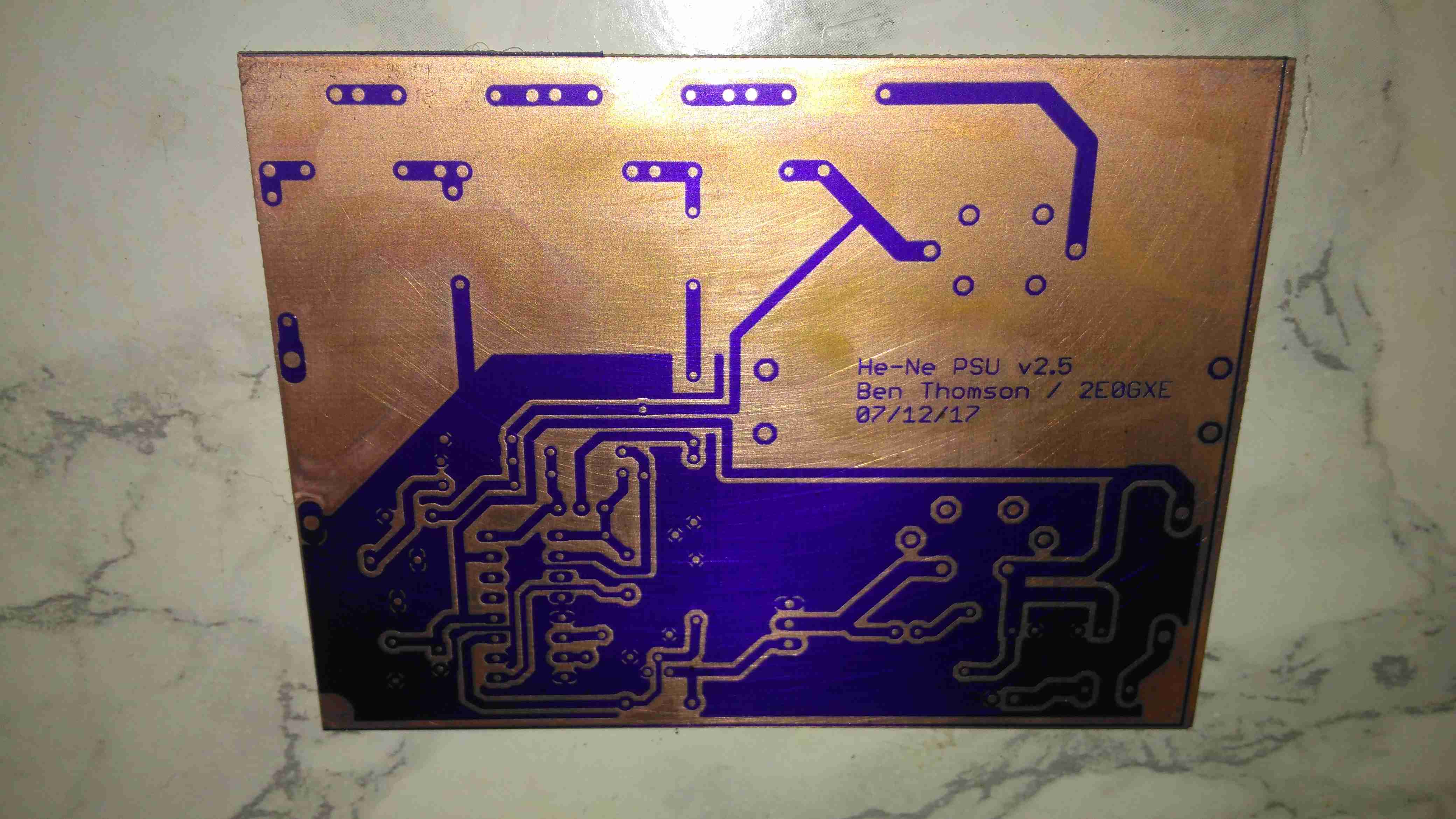
Since I do my own PCBs on a somewhat regular basis, I decided it was time to move to a more professional method to etch my boards. I have been using the cheap toner transfer method, using special yellow coated paper from China. (I think it’s coated in wax, or some plastic film).
The toner transfer paper does usually work quite well, but I’ve had many issues with pinholes in the transfer, which cause the etched tracks to look horrid, (not to mention the potential for breaks & reduced current capacity), and the toner not transferring properly at all, to issues with the paper permanently fusing to the copper instead of just transferring the toner.
BigClive has done a couple of fairly comprehensive videos on the dry film photoresist available from AliExpress & eBay. This stuff is used similarly to the toner transfer method, in that the film is fused to the board with heat, but then things diverge. It’s supplied either in cut sheets, or by the roll. I ordered a full roll to avoid the issues I’ve heard of when the stuff is folded in the post – once it’s creased, it’s totally useless. The dry film itself is a gel sandwiched between two protective plastic film sheets, and bonds to the board with the application of heat from a laminator.
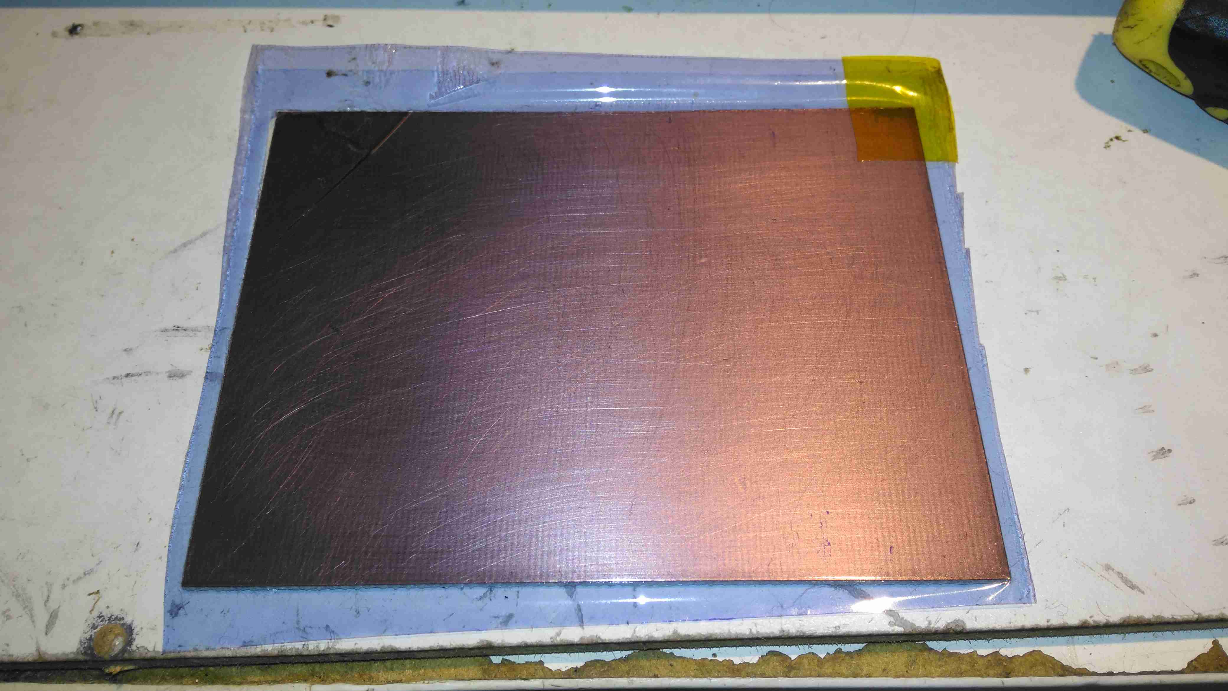
The board is first cleaned with scotchbrite pad & soap to remove any tarnish & oil from the copper.
Dry Film
Once the board has been cleaned, one side of the backing film is removed from the gel with adhesive tape, and the dry film is placed on the board while still wet. This stops the film from sticking immediately to the clean copper, one edge is pressed down, and it’s then fed through a modified laminator:
Modified Laminator
I’ve cut away most of the plastic covering the hot rollers, as constant jamming was an issue with this cheapo unit. All the mains power is safely tucked away under some remaining plastic cover at the end. The board with it’s covering of dry film is fed into the laminator – the edge that was pressed down first. This allows the laminator to squeeze out any remaining water & air bubbles from between the two so no creases or blisters form.
After Lamination
Once the board has been run through the laminator about 6 times, (enough to get it very hot to the touch), the film is totally bonded to the copper. The top film is left in place to protect the UV sensitive layer during expsure.
Photomask
The exposure mask is laser printed onto OHP transparencies, in this case I’ve found I need to use two copies overlaid to get enough opacity in the black toner sections to block the UV light. Some touching up with a Sharpie is also easy to do if there are any weak spots in the toner coverage. This film is negative type – All the black areas will be unexposed and washed off in the developer tank. I also found I had to be fairly generous with track spacing, using too small lines just causes issues with the UV curing bits of film it isn’t supposed to.
Exposing The PCB
The PCB is placed on a firm surface, the exposure mask lined up on top, and the whole thing covered with a sheet of standard glass to apply even pressure. The UV exposure lamp in this case is a cheap eBay UV nail curing unit, with 15 high power LEDs. (I’ll do a teardown on this when I get some time, it’s got some very odd LEDs in it). Exposing the board for 60 seconds is all the time needed.
After Exposure
After the board is exposed, the areas that got hit with the UV light have turned purple – the resist has hardened in these areas. It’s bloody tough as well, I’ve scrubbed at it with some vigour and it doesn’t come off. Toner transfer was a bit naff in this respect, most of the time the toner came off so easily that the etchant lifted it off. After this step is done, the remaining protective film on the top can be removed.
After Developing
The film is developed in a solution of Sodium Carbonate (washing Soda). This is mildly alkaline and it dissolves off the unexposed resist.
After Etching
Now it’s into the etching tank for a couple of minutes, I’m still using Ferric Chloride to etch my boards, at about 60°C. Etching at room temperature is much too slow. Once this is done, the board is washed, and then dipped in the strip tank for a couple of minutes. This is a Sodium Hydroxide solution, and is very caustic, so gloves are required for this bit. Getting Ferric Chloride on skin is also a fairly bad idea, it stains everything orange, and it attacks pretty much every metal it comes into contact with, including Stainless Steel.
This method does require some more effort than the toner transfer method, but it’s much more reliable. If something goes wrong with the exposure, it’s very easy to strip the board completely & start again before etching. This saves PCB material and etchant. This is definitely more suited to small-scale production as well, since the photomask can be reused, there’s much less waste at the end. The etched lines are sharper, much better defined & even with some more chemicals involved, it’s a pretty clean process. All apart from the Ferric Chloride can be disposed of down the sink after use, since the developer & stripper are just alkaline solutions.
Some time ago I posted about an ancient piece of EDA software called Stripboard Magic, which was made by a small British company by the name of Ambyr. I have been hosting copies of this now long-dead software for some time, as it still seems to be in popular demand long after being abandoned by it’s creators. I have been contacted by a reader about the existence of Service Packs for this application, which neither of us have been able to locate.
From what I have been able to gather, Ambyr ceased trading around 1999-2000, after having sold the rights to distribute Stripboard Magic to Maplin Electronics. What I’m not certain of is the timeframe of these service packs appearing, or where they could originally be found, the Ambyr website apparently vanished about 6 months after Stripboard Magic was originally released, but they were presumably intended to make the application easier to use & less buggy.
Unfortunately the timeframe for the company’s existence was before the Wayback Machine started archiving the internet, and the only record they have of Ambyr is a domain holding page dating back to 2000.
If there are any readers who have copies of these service packs, or some information on where they can be found, or indeed any more information in general about this seemingly short-lived company, please drop a comment or E-Mail me directly through the Contact Page. Inquiring minds need to know 😉
The housing of the contaminated motor was left to soak in diesel for a few hours to loosen the grok, this has come very clean. I couldn’t have used a stronger solvent here – the magnets are glued in place in the steel housing, I certainly didn’t want them coming loose!
Brushboxes
Next into the diesel bath are the motor end bells with the brushgear. Attack with a stiff brush cleaned these up very well, some cotton buds served to clean out the brass brush holders.
Armatures After Skimming
Here are both armatures, having had their commutators resurfaced. I’ve completely removed all traces of the wear caused by the contamination, luckly the commutator bars are very heavy on these motors so can take quite a bit of wear before there’s not enough left to skim. I’ve not yet pulled off the old bearings, but they are all going to be replaced with new SKF bearings, as they’ve been contaminated with grok over the years of use. I’m also going to uprate the front motor bearings to rubber sealed instead of metal shielded, to help keep lubricant out of the motors if the gearbox seals ever fail again.
Gearbox
The gearboxes have been cleaned out with some elbow grease, assisted by a long soak in petrol, I’ve refilled them here with engine oil as temporary lube & to flush out the last remains of the old grease & solvent. The worm wheel in these boxes is bronze – so a GL4 gear oil will be required. (Some Extreme Pressure additive packs contain sulphur, and will readily attack copper alloys, such as brass & bronze).
Commutator End Bearings
Here’s the armatures, after the new SKF sealed bearings have been fitted to the commutator end, above, and the drive end, below. These will cause some extra drag on the armatures, and slightly higher power consumption as a result, but keeping the crap out of the motors is slightly more important.
Drive End BearingsFresh Commutator Skim
The commutators have been lightly skimmed with abrasive cloth, and finished with 1500 grit emery. The armature on the right has been run for a short time to see how the new brushes are bedding in.
Old Seal Removed
Finally, the old oil seals are pulled from the gearboxes. The worm gear bearing on the inside is actually a sealed version, with the external oil seal providing some extra sealing. I haven’t changed the gearbox bearings, as they seem to be in good order, this might get done at some point in the future.
During the rebuild of the wheelchair motors for the support trolley, I found myself needing an accurate milliohm meter to test the armature windings with. Commercial instruments like these are expensive, but some Google searching found a milliohm meter project based around the Arduino from Circuit Cellar.
Circuit Diagram
Here’s the original author’s circuit diagram, paralleling nearly all of the Arduino’s digital output pins together to source/sink the test current, an ADS1115 ADC to take more accurate readings, with the results displayed on a jellybean 128×64 OLED module. The most expensive part here is the 10Ω 0.1% 15ppm reference resistor, R9.
I decided to make some small adjustments to the power supply section of the project, to include a rechargeable lithium cell rather than a 9v PP3 battery. This required some small changes to the Arduino sketch, a DC-DC boost converter to supply 5v from the 3.7v of a lithium cell, a charger module for said cell, and with the battery voltage being within the input range of the analogue inputs, the voltage divider on A3 was removed. A new display icon was also added in to indicate when the battery is being charged, this uses another digital input pin for input voltage sensing.
I also made some basic changes to the way an unreadable resistance is displayed, showing “OL” instead of “—–“, and the meter sends the reading out over the I²C bus, for future expansion purposes. The address the data is directed to is set to 0x50.
I’ve not etched a PCB for this as I couldn’t be bothered with the messy etchant, so I built this on a matrix board instead.
Final Prototype
Since I made some changes to both the software and the hardware components, I decided to prototype the changes on breadboard. The lithium cell is at the top of the image. with the charger module & DC-DC converter. The Arduino Nano is on the right, the ADC & reference resistor on the left, and the display at the bottom.
The Raspberry Pi & ESP8266 module are being used in this case to discharge the battery quicker to make sure the battery level calibration was correct, and to make sure the DC-DC converter would continue to function throughout the battery voltage range.
Matrix Board Passives
Here’s the final board with the passive components installed, along with the DC-DC converter. I used a Texas Instruments PTN04050 boost module for power as I had one spare.
Matrix Board Rear
The bottom of the board has most of the wire jumpers for the I²C bus, and power sensing.
Matrix Board Modules
Here’s both modules installed on the board. I used an Arduino Nano instead of the Arduino Pro Mini that the original used as these were the parts I had in stock. Routing the analogue pins is also easier on the Mini, as they’re brought out to pins in the DIP footprint, instead of requiring wire links to odd spots on the module. To secure the PCB into the case without having to drill any holes, I tapped the corner holes of the matrix board M2.5 & threaded cap head screws in. These are then spot glued to the bottom of the case to secure the finished board.
Lithium Charger
The lithium charger module is attached to the side of the enclosure, the third white wire is for input sensing – when the USB cable is plugged in a charge icon is shown on the OLED display.
Input Connections
The inputs on the side of the enclosure. I’ve used the same 6-pin round connector for the probes, power is applied to the Arduino when the probes are plugged in.
Module Installed
Everything installed in the enclosure – it’s a pretty tight fit especially with the lithium cell in place.
Meter Top Cover
The top cover has the Measure button, and the OLED display panel, the latter secured to the case with M2.5 cap head screws.
Kelvin Clips
Finally, the measurement loom, with Kelvin clips. These were an eBay buy, keeping things cheap. These clips seem to be fairly well built, even if the hinges are plastic. I doubt they’re actually gold-plated, more likely to be brass. I haven’t noticed any error introduced by these cheap clips so far.
The modified sketch is below:
// ---------------------------------------------------------------------------------------------
//  Simple, accurate milliohmeter
//
//  (c) Mark Driedger 2015
//
//  - Determines resistance using 4 wire measurement of voltage across a series connected
//  reference resistor (Rr, 10 ohm, 0.1%) and test resistor (Rx)
//  - range of accurate measurement is roughly 50 mohm to 10Kohm
//  - Uses Arduino digital I/O ports to deliver the test current, alternating polarity to cancel
//  offset errors (synchronous detector)
//  - 4 I/O pins are used for each leg of the test current to increase test current
//  - Averages 2 cycles and 100 samples/cycle
//  - Uses a 16 bit ADC ADS1115 with 16x PGA to improve accuracy
//
//  Version History
//    May 24/15    v1.0-v4.0
//      - initial development versions
//    May 27/15    v5.0
//      - changed display to I2C
//      - backed out low power module since it seemed to cause serial port upload problems
// ---------------------------------------------------------------------------------------------

#include <Wire.h>
#include <SPI.h>
#include <Adafruit_GFX.h>
#include <Adafruit_SSD1306.h>
//#include <LowPower.h>

#if (SSD1306_LCDHEIGHT != 64)
#error("Height incorrect, please fix Adafruit_SSD1306.h!");
#endif

// ---------------------------------------------------------------------------------------------
//  I/O port usage
// ---------------------------------------------------------------------------------------------
//    serial port (debug and s/w download)    0, 1
//    I²C interface to ADC & display          A4, A5
//    positive drive                          2, 3, 4, 5
//    push to test input                      8
//    unused                                  9, 10, 11, A0, A1, A2, A6, A7
//    negative drive                          6, 7, 8, 9
//    battery voltage monitor                 A3
//    debug output                            13

#define  P_PushToTest  10       // push button (measure), active low
#define  P_Debug       13
#define  CHG           12

//  ADS1115 mux and gain settings
#define  ADS1115_CH01  0x00    // p = AIN0, n = AIN1
#define  ADS1115_CH03  0x01    // ... etc
#define  ADS1115_CH13  0x02
#define  ADS1115_CH23  0x03
#define  ADS1115_CH0G  0x04    // p = AIN0, n = GND
#define  ADS1115_CH1G  0x05    // ... etc
#define  ADS1115_CH2G  0x06
#define  ADS1115_CH3G  0x07

#define  ADS1115_6p144  0x00   // +/- 6.144 V full scale
#define  ADS1115_4p096  0x01   // +/- 4.096 V full scale
#define  ADS1115_2p048  0x02   // +/- 2.048 V full scale
#define  ADS1115_1p024  0x03   // +/- 1.024 V full scale
#define  ADS1115_0p512  0x04   // +/- 0.512 V full scale
#define  ADS1115_0p256  0x05   // +/- 0.256 V full scale
#define  ADS1115_0p256B 0x06   // same as ADS1115_0p256
#define  ADS1115_0p256C 0x07   // same as ADS1115_0p256

Adafruit_SSD1306   display(0);               // using I2C interface, no reset pin
static int         debug_mode = 0;           // true in debug mode

float ADS1115read(byte channel, byte gain)
//--------------------------------------------------------------------------------------
//  reads a single sample from the ADS1115 ADC at a given mux (channel) and gain setting
//  - channel is 3 bit channel number/mux setting (one of ADS1115_CHxx)
//  - gain is 3 bit PGA gain setting (one of ADS1115_xpxxx)
//  - returns voltage in volts
//  - uses single shot mode, polling for conversion complete, default I2C address
//  - conversion takes approximatly 9.25 msec
//--------------------------------------------------------------------------------------
  {
  const int    address = 0x48;      // ADS1115 I2C address, A0=0, A1=0
  byte         hiByte, loByte;
  int          r;
  float        x;

  channel &= 0x07;                  // constrain to 3 bits
  gain    &= 0x07;

  hiByte = B10000001 | (channel<<4) | (gain<<1);    // conversion start command
  loByte = B10000011;

  Wire.beginTransmission(address);  // send conversion start command
  Wire.write(0x01);                 // address the config register
  Wire.write(hiByte);               // ...and send config register value
  Wire.write(loByte);
  Wire.endTransmission();

   do                               // loop until conversion complete
    {
    Wire.requestFrom(address, 2);   // config register is still addressed
    while(Wire.available())
      {
      hiByte = Wire.read();         // ... and read config register
      loByte = Wire.read();
      }
    }
  while ((hiByte & 0x80)==0);       // upper bit (OS) is conversion complete

  Wire.beginTransmission(address);
  Wire.write(0x00);                 // address the conversion register
  Wire.endTransmission();

  Wire.requestFrom(address, 2);     // ... and get 2 byte result
  while(Wire.available())
    {
    hiByte = Wire.read();
    loByte = Wire.read();
    }

  r = loByte | hiByte<<8;           // convert to 16 bit int
  switch(gain)                      // ... and now convert to volts
    {
      case ADS1115_6p144:  x = r * 6.144 / 32768.0; break;
      case ADS1115_4p096:  x = r * 4.096 / 32768.0; break;
      case ADS1115_2p048:  x = r * 2.048 / 32768.0; break;
      case ADS1115_1p024:  x = r * 1.024 / 32768.0; break;
      case ADS1115_0p512:  x = r * 0.512 / 32768.0; break;
      case ADS1115_0p256:
      case ADS1115_0p256B:
      case ADS1115_0p256C: x = r * 0.256 / 32768.0; break;
    }
  return x;
  }

// ---------------------------------------------------------------------------------------------
//  Drive functions
//   - ports 4-7 and A0-A3 are used to differentially drive resistor under test
//   - the ports are resistively summed to increase current capability
//   - DriveOff() disables the drive, setting the bits to input
//   - DriveOn()  enables the drive,  setting the bits to output
//   - DriveP()   enables drive with positive current flow (from ports 4-7 to ports A0-A3)
//   - DriveN()   enables drive with negative current flow
// ---------------------------------------------------------------------------------------------
void DriveP()
  {
    DriveOff();
    digitalWrite( 2, HIGH);
    digitalWrite( 3, HIGH);
    digitalWrite( 4, HIGH);
    digitalWrite( 5, HIGH);
    digitalWrite( 6, LOW);
    digitalWrite( 7, LOW);
    digitalWrite( 8, LOW);
    digitalWrite( 9, LOW);
    DriveOn();
  }

void DriveN()
  {
    DriveOff();
    digitalWrite( 2, LOW);
    digitalWrite( 3, LOW);
    digitalWrite( 4, LOW);
    digitalWrite( 5, LOW);
    digitalWrite( 6, HIGH);
    digitalWrite( 7, HIGH);
    digitalWrite( 8, HIGH);
    digitalWrite( 9, HIGH);
    DriveOn();
  }

void DriveOn()
  {
    pinMode( 2, OUTPUT);      // enable source/sink in pairs
    pinMode( 6, OUTPUT);
    pinMode( 3, OUTPUT);
    pinMode( 7, OUTPUT);
    pinMode( 4, OUTPUT);
    pinMode( 8, OUTPUT);
    pinMode( 5, OUTPUT);
    pinMode( 9, OUTPUT);
    delayMicroseconds(5000);  // 5ms delay
  }

void DriveOff()
  {
    pinMode( 2, INPUT);       // disable source/sink in pairs
    pinMode( 6, INPUT);
    pinMode( 3, INPUT);
    pinMode( 7, INPUT);
    pinMode( 4, INPUT);
    pinMode( 8, INPUT);
    pinMode( 5, INPUT);
    pinMode( 9, INPUT);
  }

int CalcPGA(float x)
// ---------------------------------------------------------------------------------------------
//   Calculate optimum PGA setting based on a sample voltage, x, read at lowest PGA gain
//     - returns the highest PGA gain that allows x to be read with 10% headroom
// ---------------------------------------------------------------------------------------------
  {
    x = abs(x);
    if (x>3.680) return ADS1115_6p144;
    if (x>1.840) return ADS1115_4p096;
    if (x>0.920) return ADS1115_2p048;
    if (x>0.460) return ADS1115_1p024;
    if (x>0.230) return ADS1115_0p512;
    else         return ADS1115_0p256;
  }

void BatteryIcon(float charge)
// ---------------------------------------------------------------------------------------------
//   Draw a battery charge icon into the display buffer without refreshing the display
//     - charge ranges from 0.0 (empty) to 1.0 (full)
// ---------------------------------------------------------------------------------------------
  {
    static const unsigned char PROGMEM chg[] =     // Battery Charge Icon
    { 0x1c, 0x18, 0x38, 0x3c, 0x18, 0x10, 0x20, 0x00 };

    int w = constrain(charge, 0.0, 1.0)*16;  // 0 to 16 pixels wide depending on charge
    display.drawRect(100, 0, 16, 7, WHITE);  // outline
    display.drawRect(116, 2,  3, 3, WHITE);  // nib
    display.fillRect(100, 0,  w, 7, WHITE);  // charge indication

    //battery charging indication
    pinMode(CHG, INPUT);
    if (digitalRead(CHG) == HIGH)
      display.drawBitmap(91, 0, chg, 8, 8, WHITE);
  }

void f2str(float x, int N, char *c)
// ---------------------------------------------------------------------------------------------
//    Converts a floating point number x to a string c with N digits of precision
//     - *c must be a string array of length at least N+3 (N + '-', '.', '\0')
//     - x must be have than N leading digits (before decimal) or "#\0" is returned
// ---------------------------------------------------------------------------------------------
  {
  int     j, k, r;
  float   y;

  if (x<0.0)                    // handle negative numbers
    {
      *c++ = '-';
      x = -x;
    }
  for (j=0; x>=1.0; j++)        // j digits before decimal point
    x /= 10.0;                  // .. and scale x to be < 1.0

  if (j>N)                      // return error string if too many digits
    {
      *c++ = '#';
      *c++ = '\0';
      return;
    }

  y = pow(10, (float) N);       // round to N digits
  x = round(x * y) / y;
  if (x>1.0)                    // if 1st digit rounded up ...
    {
      x /= 10.0;                // then normalize back down 1 digit
      j++;
    }

  for (k=0; k<N; k++)
    {
      r = (int) (x*10.0);        // leading digit as int
      x = x*10-r;                // remove leading digit and shift 1 digit

      *c++ = r + '0';            // add leading digit to string
      if (k==j-1 && k!=N-1)      // add decimal point after j digits
        *c++ = '.';              // ... unless there are N digits before decimal
    }
  *c++ = '\0';
  }

void DisplayResistance(float x)
// ---------------------------------------------------------------------------------------------
//    Adds the resistance value, x, to the display buffer without refreshing the display
//      - converts to kohm, milliohm or microohm if necessary
// ---------------------------------------------------------------------------------------------
  {
    static const unsigned char PROGMEM omega_bmp[] =     // omega (ohm) symbol
    { B00000011, B11000000,
      B00001100, B00110000,
      B00110000, B00001100,
      B01000000, B00000010,
      B01000000, B00000010,
      B10000000, B00000001,
      B10000000, B00000001,
      B10000000, B00000001,
      B10000000, B00000001,
      B10000000, B00000001,
      B01000000, B00000010,
      B01000000, B00000010,
      B01000000, B00000010,
      B00100000, B00000100,
      B00010000, B00001000,
      B11111000, B00011111 };

    char  s[8];
    char  prefix;

    if (x>=1000.0)          // display in killo ohms
      {
        x /= 1000.0;
        prefix = 'k';
      }
    else if (x<0.001)       // display in micro ohms
      {
        x *= 1000000.0;
        prefix = 0xe5;    // mu
      }
    else if (x<1.0)         // display in milli ohms
      {
        x *= 1000.0;
        prefix = 'm';
      }
    else
      prefix = ' ';         // display in ohms

    f2str(x, 5, s);

    // display computed resistance
    display.setTextSize(2);
    display.setTextColor(WHITE);
    display.setCursor(0,20);
    display.print(s);

    // display prefix
    display.setCursor(85,20);
    display.print(prefix);

    // display omega (ohms) symbol
    display.drawBitmap(103, 18, omega_bmp, 16, 16, WHITE);
  }

void DisplayDebug(int a, int b, float x, float y, float Vbat)
// ---------------------------------------------------------------------------------------------
//    Adds debug info to the display buffer without showing the updated display
//      - Adds 2 ints (a, b) and a float(Vbat) to the top line and 2 floats (x, y)
//      to the bottom line+, all in small (size 1) text
// ---------------------------------------------------------------------------------------------
  {
    // display x, y in lower left, small font
    display.setTextSize(1);
    display.setCursor(0,45);
    display.print(x,3);
    display.print("  ");
    display.print(y,3);

    // display a, b in upper left, small font
    display.setTextSize(1);
    display.setCursor(0,0);
    display.print(a);
    display.print("  ");
    display.print(b);

    // display Vbat in upper middle, small font
    display.setTextSize(1);
    display.setCursor(60,0);
    display.print(Vbat,1);
  }

void DisplayStr(char *s)
// ---------------------------------------------------------------------------------------------
//    Adds a string, s, to the display buffer without refreshing the display @ (0,20)
// ---------------------------------------------------------------------------------------------
  {
    display.setTextSize(2);
    display.setTextColor(WHITE);
    display.setCursor(8,20);
    display.print(s);
  }

#ifdef TESTMODE
void loop()
  {
    while (digitalRead(P_PushToTest))
      ;
    DriveP();
    display.clearDisplay();
    DisplayStr("Drive: +");
    display.display();
    delay(250);

    while (digitalRead(P_PushToTest))
      ;
    DriveN();
    display.clearDisplay();
    DisplayStr("Drive: -");
    display.display();
    delay(250);

    while (digitalRead(P_PushToTest))
      ;
    DriveOff();
    display.clearDisplay();
    DisplayStr("Drive: Off");
    display.display();
    delay(250);
  }
#endif

void setup()
// ---------------------------------------------------------------------------------------------
//    - initializae display and I/O ports
// ---------------------------------------------------------------------------------------------
  {
    DriveOff();                                    // disable current drive
    Wire.begin();                                  // join I2C bus
    display.begin(SSD1306_SWITCHCAPVCC, 0x3c, 0);  // initialize display @ address 0x3c, no reset
    pinMode(P_PushToTest, INPUT_PULLUP);           // measure push button switch, active low
    debug_mode = !digitalRead(P_PushToTest);       // if pushed during power on, then debug mode
    pinMode(P_Debug, OUTPUT);                      // debug port
  }

void loop()
// ---------------------------------------------------------------------------------------------
//    main measurement loop
// ---------------------------------------------------------------------------------------------
  {
    const float      Rr = 10.0;             // reference resistor value, ohms
    const float      Rcal = 1.002419;       // calibration factor
    const int        N = 2;                 // number of cycles to average
    const int        M = 50;                // samples per half cycle
    static long      Toff;
    double           Rx;                    // calculated resistor under test, ohms
    byte             PGAr, PGAx;            // PGA gains (r = reference, x = test resistors)
    float            Vr, Vx, Wx, Wr;        // voltages in V
    float            Rn;                    // calculated resistor under test, ohms, single sample
    double           Avgr, Avgx;            // average ADC readings in mV
    int              j, k, n;
    float            Vbat;                  // battery voltage in V (from 2:1 divider)
    char             serialbuff[10];        // Buffer for sending the reading over I²C

    display.clearDisplay();
    DisplayStr("measuring");
    display.display();

    // determine PGA gains
    DriveP();
    Wr =  ADS1115read(ADS1115_CH01, ADS1115_6p144);
    Wx =  ADS1115read(ADS1115_CH23, ADS1115_6p144);
    DriveN();
    Vr = -ADS1115read(ADS1115_CH01, ADS1115_6p144);
    Vx = -ADS1115read(ADS1115_CH23, ADS1115_6p144);

    //  measure battery voltage ... while drive is on so there is a load
    Vbat = analogRead(A3)*5.0/1024.0;    // 2:1 divider (5V FS) on 4.2v lithium battery

    DriveOff();

    PGAr = CalcPGA(max(Vr, Wr));           // determine optimum PGA gains
    PGAx = CalcPGA(max(Vx, Wx));

    // measure resistance using synchronous detection
    Avgr = Avgx = 0.0;                     // clear averages
    Rx = 0.0;
    n = 0;
    for (j=0; j<N; j++)                    // for each cycle
      {
        DriveP();                          // turn on drive, positive
        for (k=0; k<M; k++)
          {
            digitalWrite(P_Debug, 1);
            Vx = ADS1115read(ADS1115_CH23, PGAx);
            digitalWrite(P_Debug, 0);
            Vr = ADS1115read(ADS1115_CH01, PGAr);
            Avgx += Vx;
            Avgr += Vr;
            Rn = Vx/Vr;
            if (Rn>0.0 && Rn<10000.0)
              {
              Rx += Rn;
              n++;
              }
          }

        DriveN();                          // turn on drive, negative
        for (k=0; k<M; k++)
          {
            digitalWrite(P_Debug, 1);
            Vx = ADS1115read(ADS1115_CH23, PGAx);
            digitalWrite(P_Debug, 0);
            Vr = ADS1115read(ADS1115_CH01, PGAr);
            Avgx -= Vx;
            Avgr -= Vr;
            Rn = Vx/Vr;
            if (Rn>0.0 && Rn<10000.0)
              {
              Rx += Rn;
              n++;
              }
          }
      }

    DriveOff();
    Rx   *= Rr * Rcal / n;                 // apply calibration factor and compute average
    Avgr *= 1000.0 / (2.0*N*M);            // average in mV
    Avgx *= 1000.0 / (2.0*N*M);

    // display the results ... battery icon, Rx measurement, debug info if requested
    display.clearDisplay();                // ... and display result
    BatteryIcon((Vbat-3.0)/(4.2-3.0));     // 7.5V = 0%, 9V = 100%
    //display.drawLine(0, 8, 127, 8, WHITE); //Draw separator line under icons
    if (n==0){                              // no measurement taken ...
      display.setTextSize(2);
      display.setCursor(51,20);
      display.print(F("OL"));
    }
      //DisplayStr("-----");
    else
      DisplayResistance(Rx);
    //Send Reading via I²C
      Wire.beginTransmission(0x50);
      Wire.write(dtostrf(Rx, 5, 5, serialbuff));
      Wire.endTransmission();
    if (debug_mode)
      DisplayDebug(PGAr, PGAx, Avgr, Avgx, Vbat);
    display.display();                     // show the display

    // and then wait for next measurement request
    Toff = millis()+60000L;
    while(digitalRead(P_PushToTest))       // loop until measure button pressed
      {
        // Enter power down state for 120ms with ADC and BOD module disabled
        //LowPower.powerDown(SLEEP_120MS, ADC_OFF, BOD_OFF);
        if (millis()>Toff)                 // after 7 seconds ...
          {
            display.clearDisplay();        // clear display
            display.display();
          }
      }
  }
Tip Jar
If you’ve found my content useful, please consider leaving a donation by clicking the Tip Jar below!
All collected funds go towards new content & the costs of keeping the server online.