Posted on Leave a comment

Yellow Jacket Titan P51-870 Digital Manifold Teardown

Front Panel & LCD
Front Panel & LCD
Front Panel & LCD

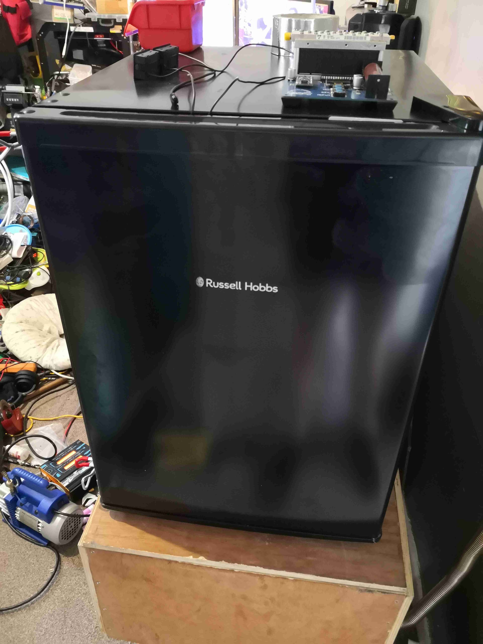
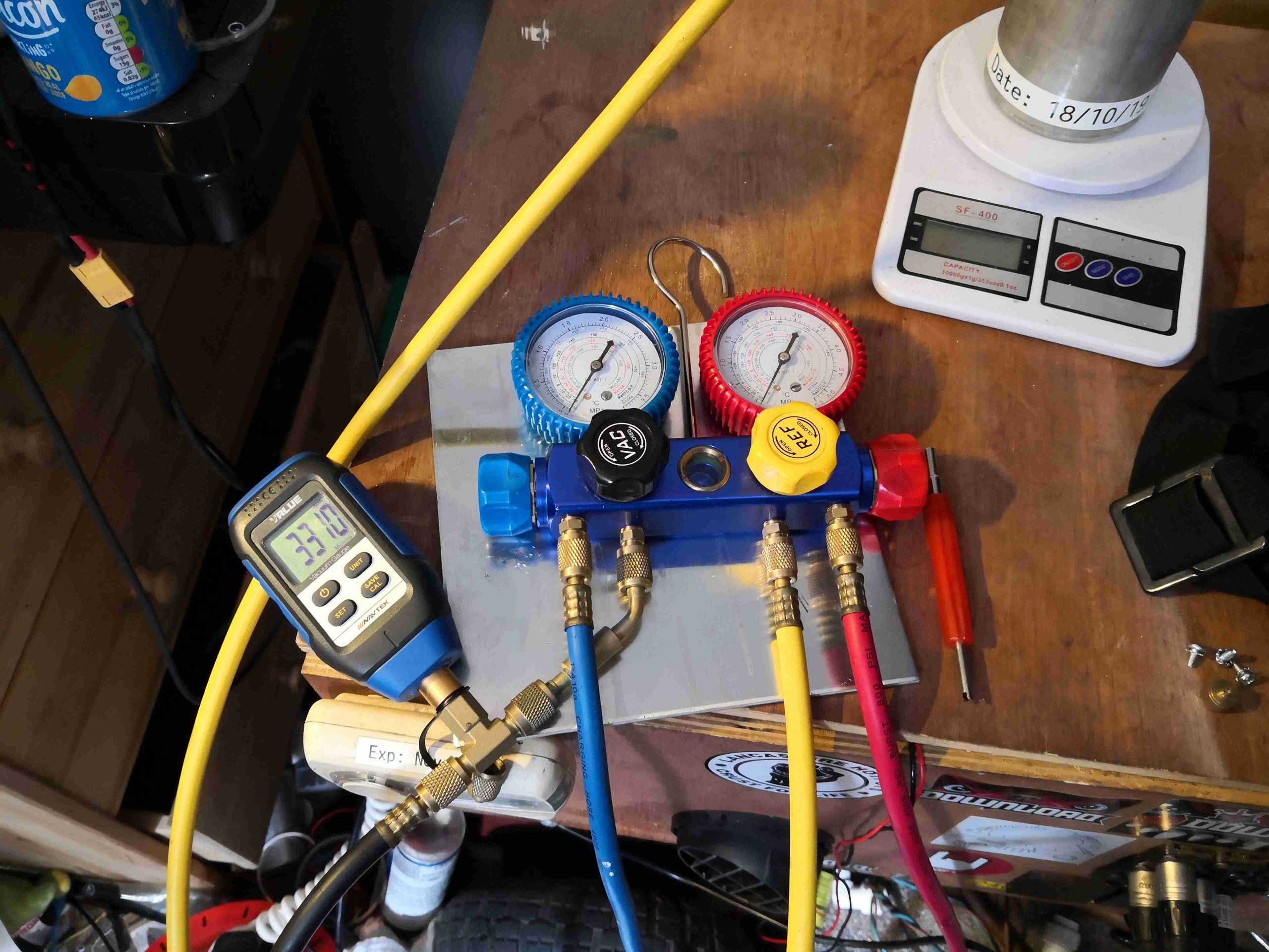
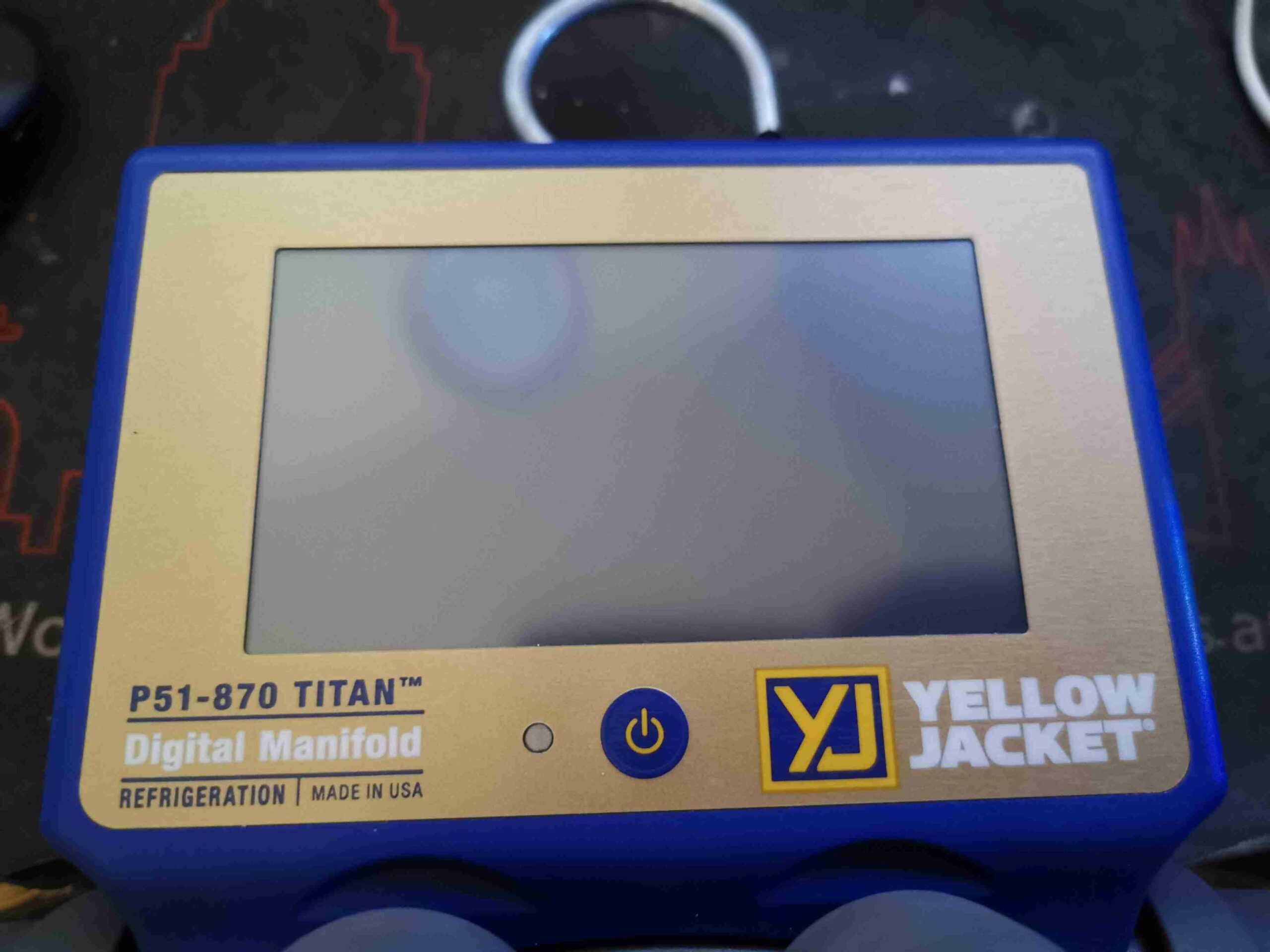
New tool time! I figured now I’m a fully ticketed member of the F-Gas community, I’d treat myself to passing the course by buying a decent set of refrigeration gauges. This is the Yellow Jacket P51-870 Titan manifold, a fully digital unit with all the useful functions built in. Basically an electronic module attached on the top of the standard Titan manifold, this unit performs all the regular functions I’d normally need either a calculator for, or other tools. The front of the unit has just a power button, LED & a large resistive touch TFT panel for display.

Rear Panel
Rear Panel

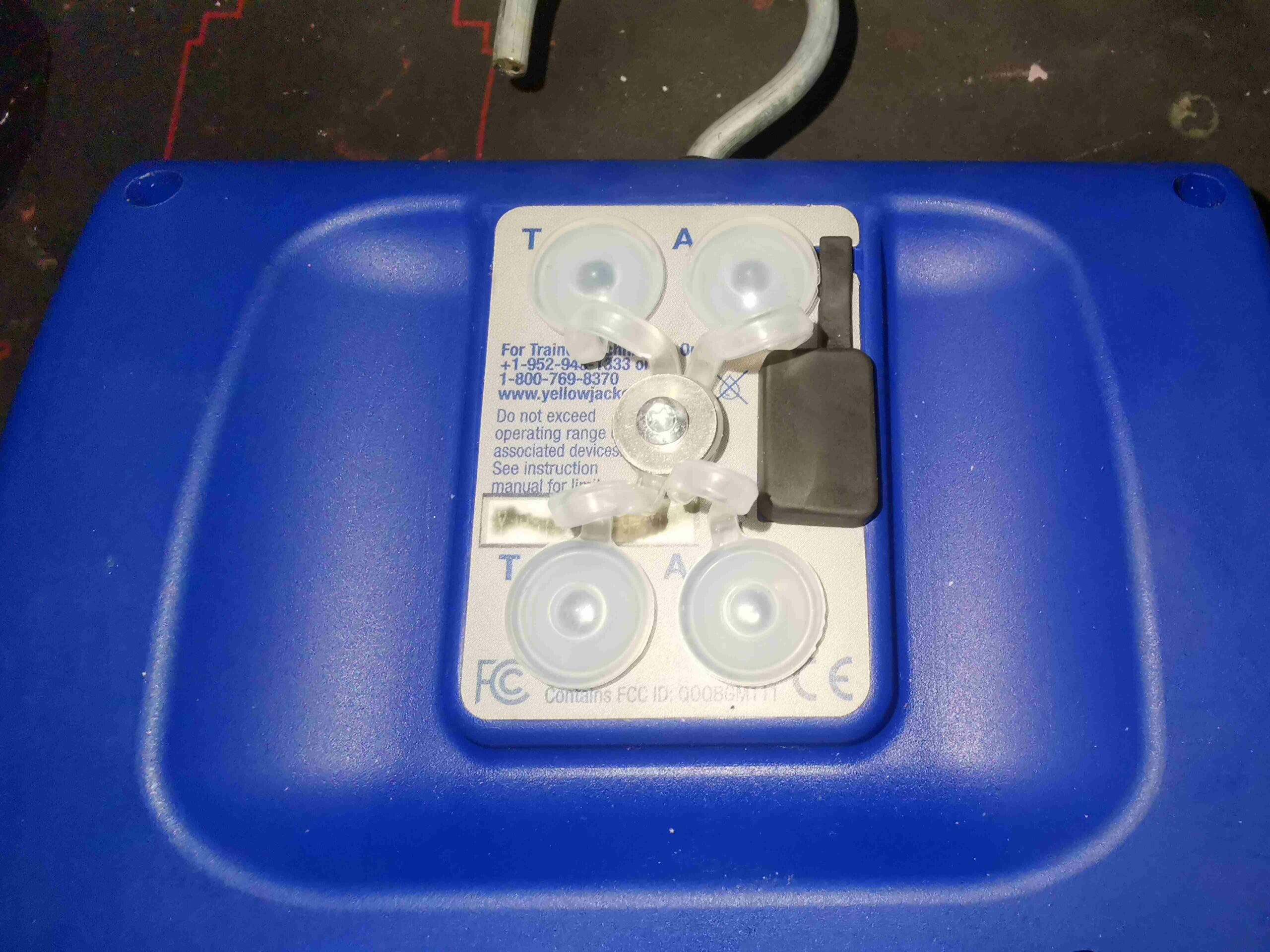
The rear panel has the ports for charging the internal battery, which is micro USB – this is also used to download log data to a PC from a system processing run. There are 4 3.5mm jacks for the external temperature probes, and vacuum sensor.

Rear Cover Removed
Rear Cover Removed

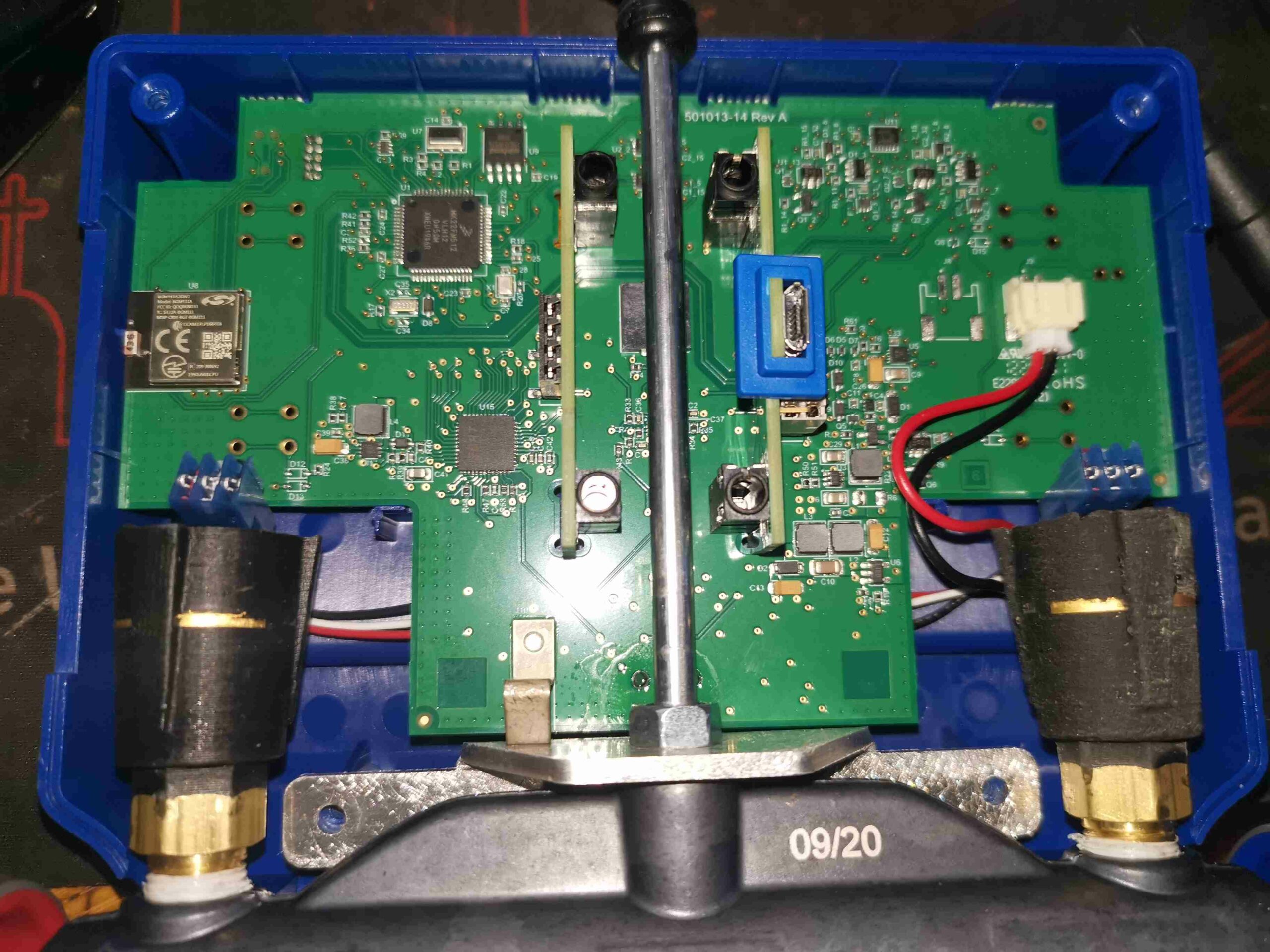
Removing 4 Torx screws in the back panel allows the clamshell case to come apart, showing the mainboard, and the pressure transducers screwed into the manifold. The aux jacks & the USB charging & data port are supported on small vertical PCBs plugged into the mainboard via 0.1″ headers.

Main PCB Overview
Main PCB Overview

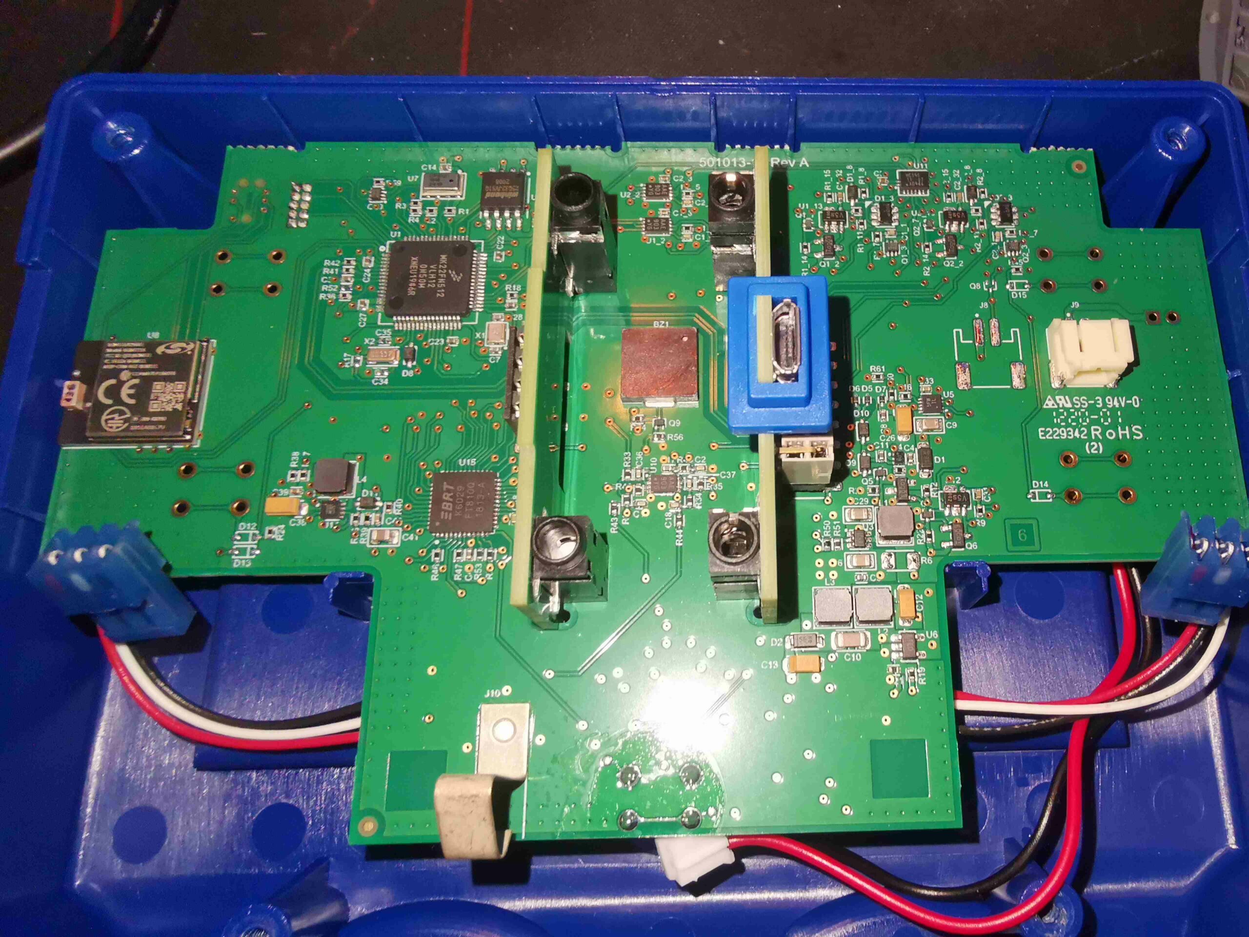
With the pressure transducers unplugged from their looms to the mainboard, the module is free from the manifold section.

Main Microcontroller

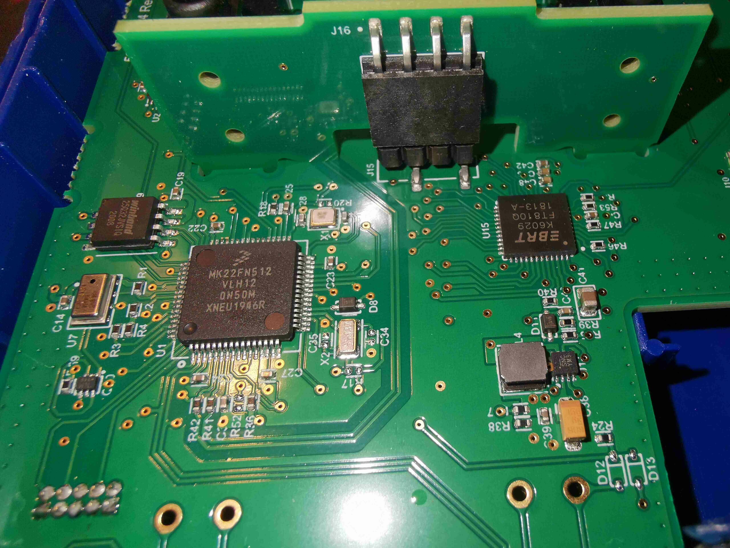
The muscle of the operation here is a Freescale (now NXP) Kinetis K2 Series MK22FN512VLH12 ARM microcontroller. With a Cortex-M4 core at 120MHz, there’s a bit of beef here. The LCD & touch overlay is controlled by a Bridgetek FT810Q Embedded Video Engine. The video controller communicates with the microcontroller via SPI, and the LCD via parallel RGB. There’s some SPI Flash memory up on the left, for log data storage, a Winbond W25Q32JV 32Mbit part. Just under that is a pressure sensor, which I’ve been so far unable to pull a part number off. This is required to assist in calibration of the main pressure transducers.


Switching Section
Switching Section

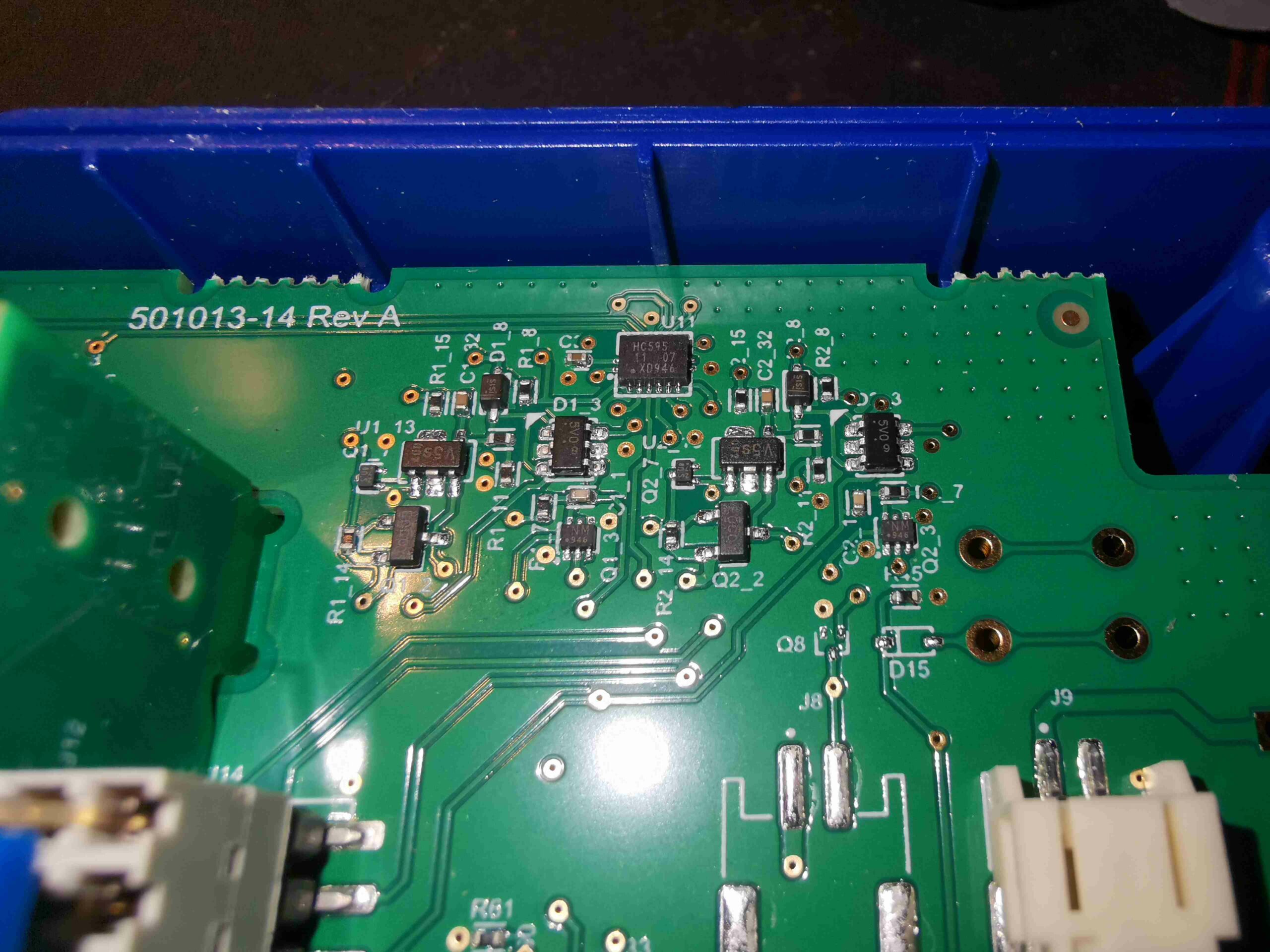
In the top right corner of the board is a 74HC595 shift register, with quite a few discrete transistors & diodes hanging around it. I suspect this is used to switch between two vacuum sensors when both are plugged in – from looking at the waveforms present on the sensor interface, the power does appear to be switched ON/OFF on a single sensor at about 1Hz.

My guess at the moment is that the sensor communications are over I²C, by the 4-wire connection, and the very obvious clock & data line on the connector, but I haven’t yet looked deeply into this.

Main Power Supplies
Main Power Supplies

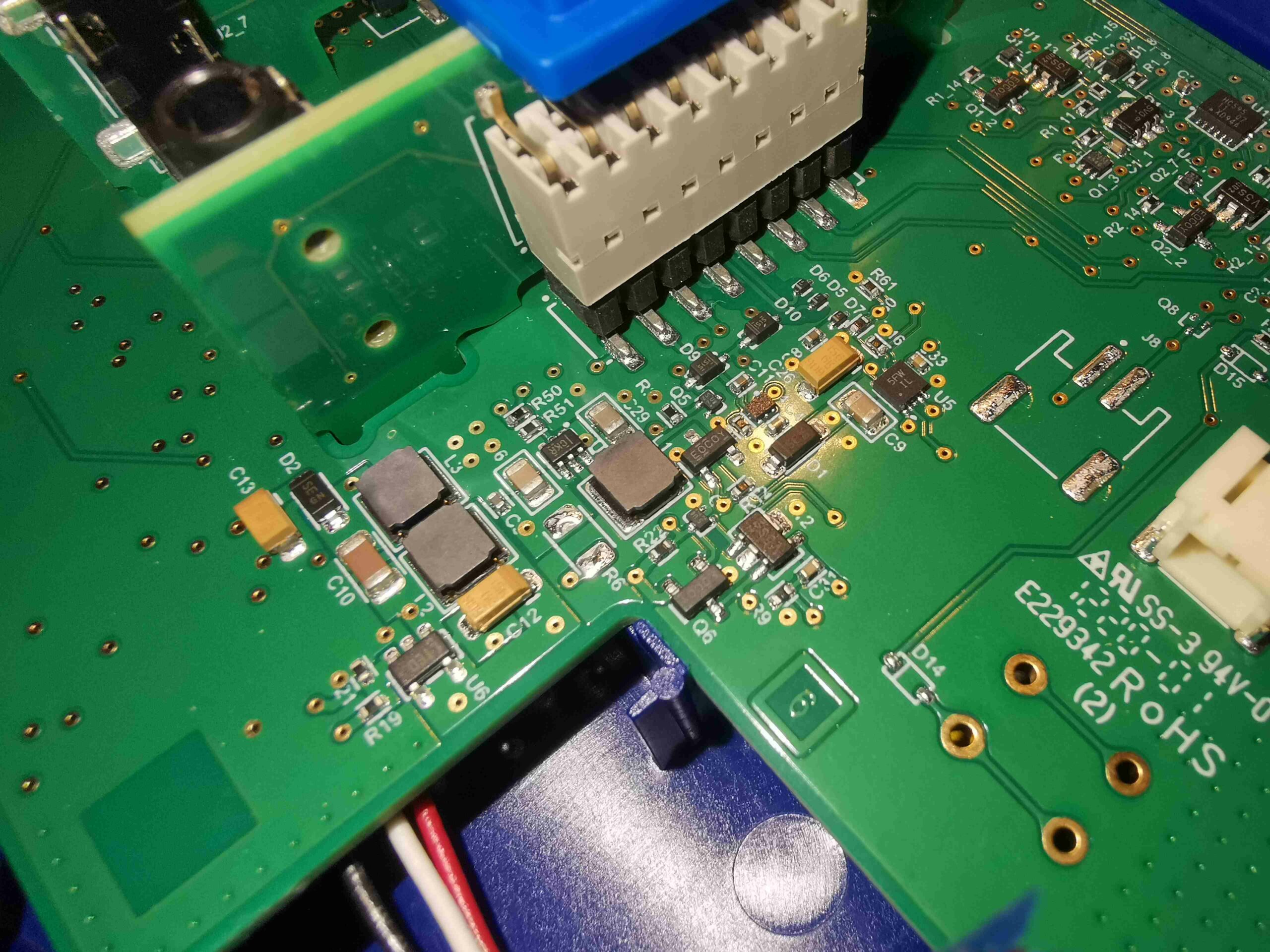
Next to the battery connector (the battery itself is a single LiPo pouch cell, double-sided taped to the front shell, behind the display), are a selection of DC-DC converters, providing all the required voltage rails. No doubt there’s lithium charging control going on here too.

Bluetooth Module
Bluetooth Module

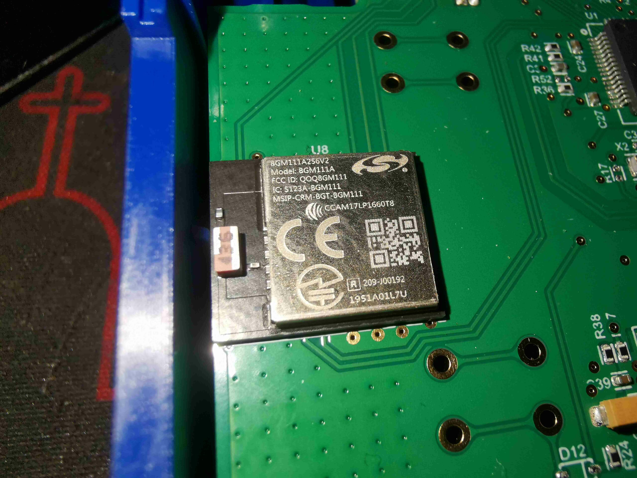
Wireless connectivity is provided for by a Silicon Labs Blue Gecko BGM111A256V2 Bluetooth 4.2 SoC module. These are also fairly powerful parts, with a full ARM Cortex M4 microcontroller hiding inside, clocked at 40MHz. There are as a result two programming headers on this board, in the top left corner, for both this part & the main microcontroller.

Posted on Leave a comment

Undercounter Fridge – Conversion for 12 Volt Use

Since I do a lot of camping, and several festivals per year (when there isn’t a pandemic on!), I identified the need for a proper fridge that can be powered from my solar setup. Such fridges & coolers already exist, that run from either mains AC, 12/24v DC, and some of them (absorption cycle) will run from bottled gas.

The last option is out, as they’re hideously inefficient, and this would require the carrying around of a flammable gas source. Ready-made units using the vapour-compression method used in all domestic & industrial refrigeration, but they are very expensive. For an upright fridge type unit that could store enough to feed a family of 4, I was looking at over £550+VAT. A cheaper option was definitely required.

Since I already have a couple of spare Danfoss BD35 DC refrigeration compressors, I decided to grab a cheap domestic mini-fridge, and perform a compressor-ectomy to make the unit operable on a low voltage supply.

Russel Hobbs Mini-Fridge

Here’s the fridge I obtained from one of the many suppliers of domestic kit, this is a Russel Hobbs branded mini-fridge.

Factory Compressor
Factory Compressor

I was careful to select a unit with no Aluminium pipework – the stuff is damn near impossible to join onto with soldering. Brazing is impossible due to the temperatures involved. These units have copper & steel in their circuit, so this will be easy. Factory charge is 16g of R600a (Isobutane). This one isn’t even going to make it to the point of being plugged in before modification!

BD35 Fitted
BD35 Fitted

I evacuated the factory charge, and removed the original compressor. To avoid having to disturb the capillary tube, I ensured the system was in continual nitrogen purge to keep moisture out – this meant I could retain the factory filter-drier. The condenser in this fridge is skin-type, on both sides of the outer shell, and formed from steel tube. This connection required the use of silver braze to connect to the compressor.
The suction line from the evaporator is copper, so that’s an easy braze onto an extension to the compressor.

New System Charging
New System Charging

Once the new compressor was brazed into place, a full leak & pressure strength test is performed. I’m using isolation valves on the charging hoses here – they’re quite nifty. Backseat them all the way & the charging hose is isolated from the system. Front seat all the way & the hose valve is opened, and the Schrader valve core is depressed in the service port. They really cut losses when charging systems with Schraders!

Vacuum Stage
Vacuum Stage

Next step is applying a vacuum to the system. I aimed for a final vacuum of 250 microns. This by far takes the longest amount of time in a refrigeration job. For reliability & longevity of the system, it’s imperative that all contaminants such as water vapour & air are removed from the circuit.

Refrigerant Bottle
Refrigerant Bottle

The final step is a refrigerant charge. Since I’m not at all fond of flammable refrigerants in this use case (camping), I broke out the bottle of R-134a. This isn’t ideal, as the capillary tube will be sized for the original charge of R600a, but the effect on efficiency shouldn’t be too terrible. (There will be a drop in COP, but I haven’t yet measured the actual COP of the re-engineered system). Unfortunately, as this uses a plate evaporator with a built in capillary tube, there’s no way to resize this for another gas. The capillary tube is fed down the centre of the suction line in these systems, to increase efficiency of the cycle.

Evaporator
Evaporator

A few minutes after an initial charge of 45g R-134a, there’s frost on the plate evaporator! Since this is a gas change as well as the compressor, there’s no other way than to charge slowly, and wait for the system to stabilize at temperature. Then gas is added until there’s an even frost all over the evaporator surface. I would have measured the charge by suction line superheat, but I have no idea of the original system specifications.

Suction Line Icing
Suction Line Icing

In this case, when running the cabinet down to the minimum temperature possible, a slight overcharge became evident. Releasing a small amount of the refrigerant back into the charging bottle sorted this out.

I may yet make another modification to this unit, to remove the skin-condenser from the circuit. While cheap, and difficult to damage as they’re buried behind the outer case metal, they’re not very efficient. I have some small fan-cooled condenser coils that will probably end up in the back next to the compressor to improve efficiency. This will also take some of the heat load off the cabinet insulation, as there won’t be a coil of hot refrigerant next to it.