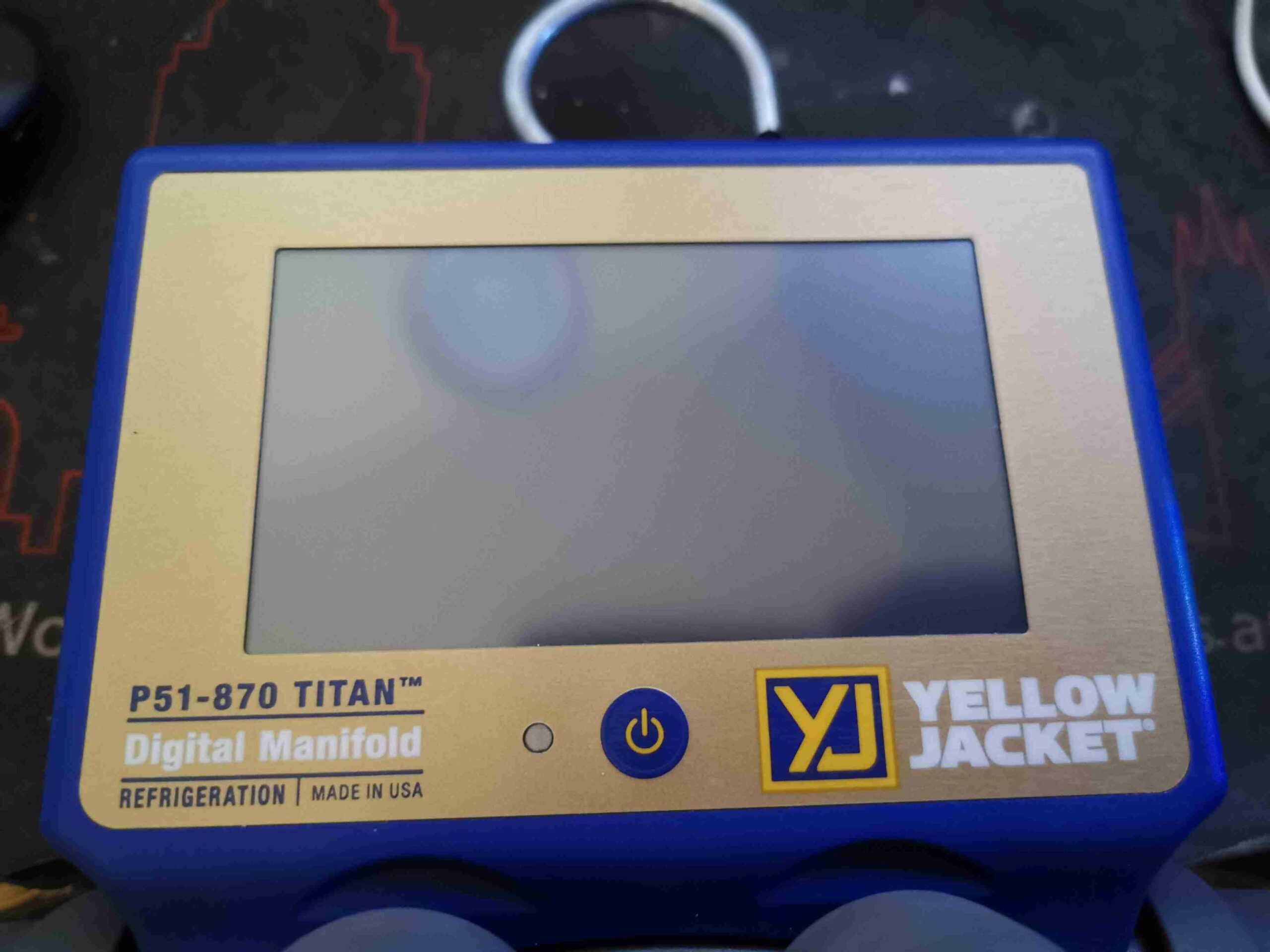
New tool time! I figured now I’m a fully ticketed member of the F-Gas community, I’d treat myself to passing the course by buying a decent set of refrigeration gauges. This is the Yellow Jacket P51-870 Titan manifold, a fully digital unit with all the useful functions built in. Basically an electronic module attached on the top of the standard Titan manifold, this unit performs all the regular functions I’d normally need either a calculator for, or other tools. The front of the unit has just a power button, LED & a large resistive touch TFT panel for display.
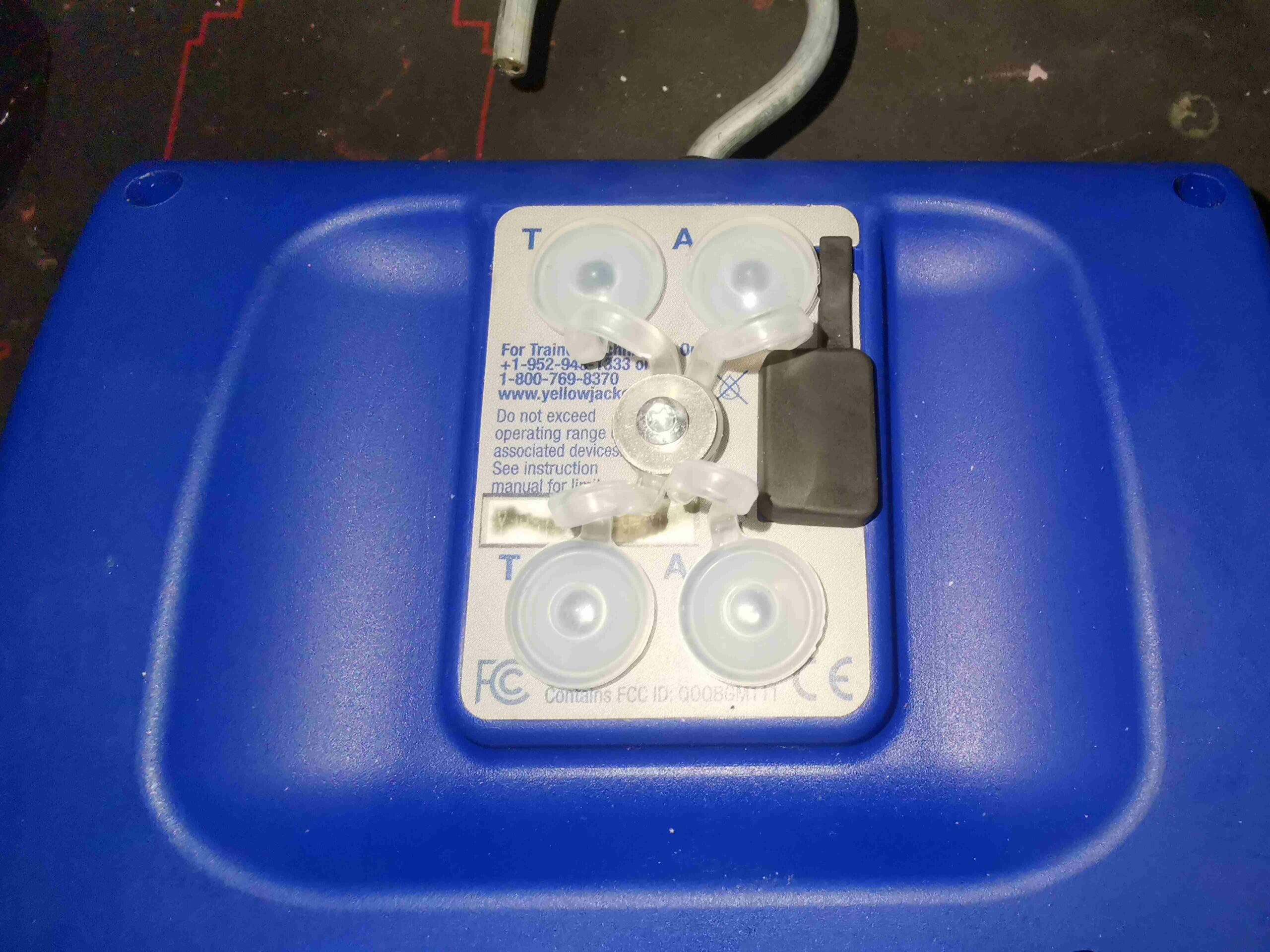
The rear panel has the ports for charging the internal battery, which is micro USB – this is also used to download log data to a PC from a system processing run. There are 4 3.5mm jacks for the external temperature probes, and vacuum sensor.
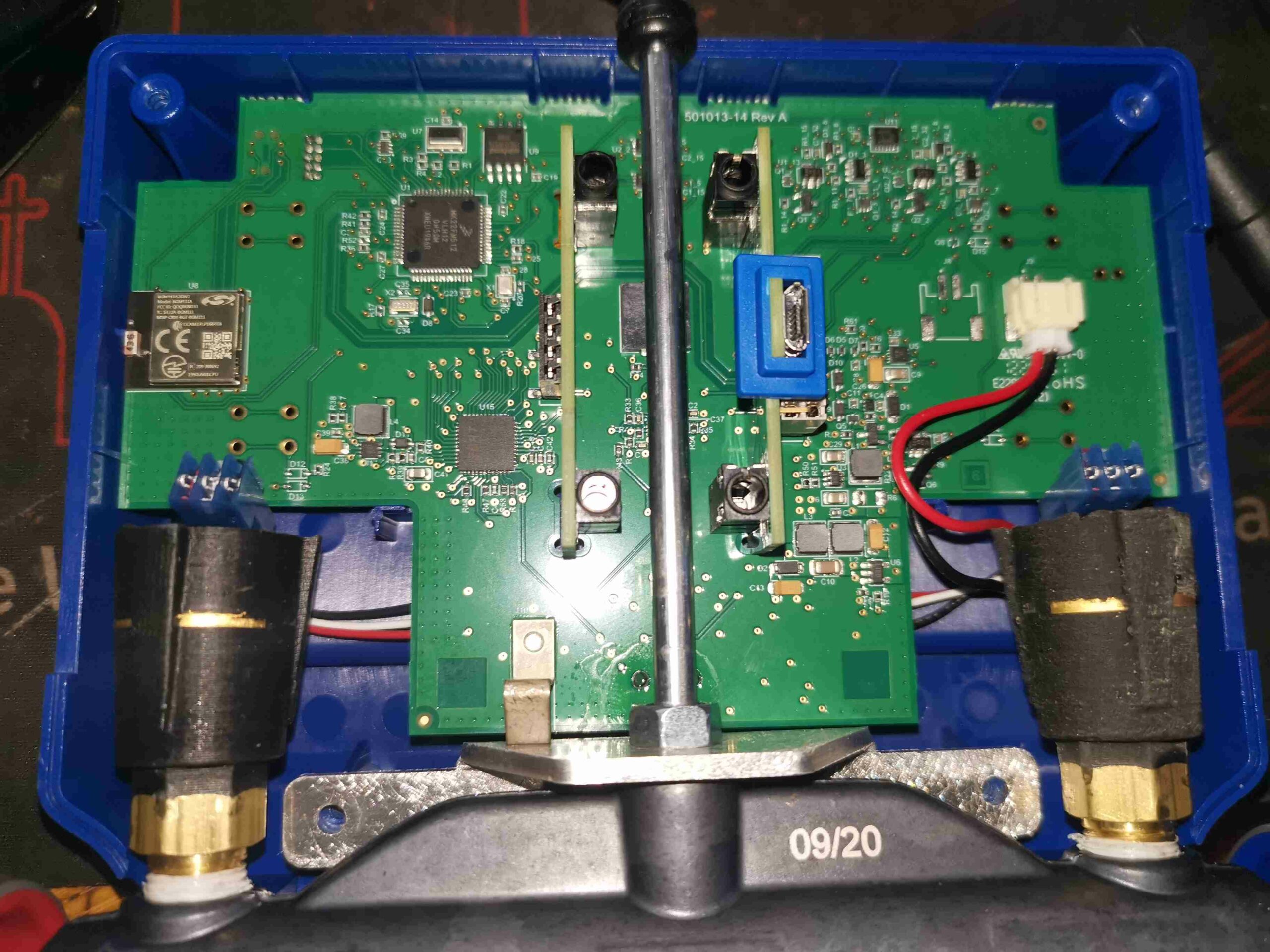
Removing 4 Torx screws in the back panel allows the clamshell case to come apart, showing the mainboard, and the pressure transducers screwed into the manifold. The aux jacks & the USB charging & data port are supported on small vertical PCBs plugged into the mainboard via 0.1″ headers.
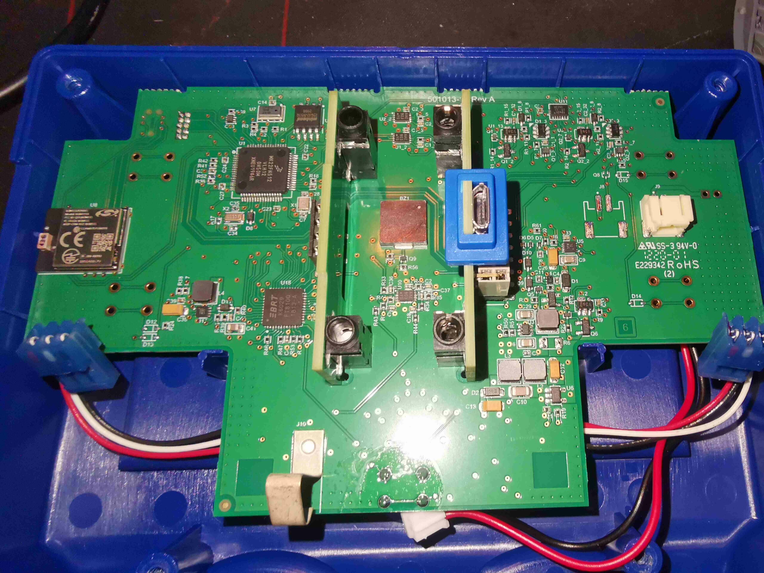
With the pressure transducers unplugged from their looms to the mainboard, the module is free from the manifold section.
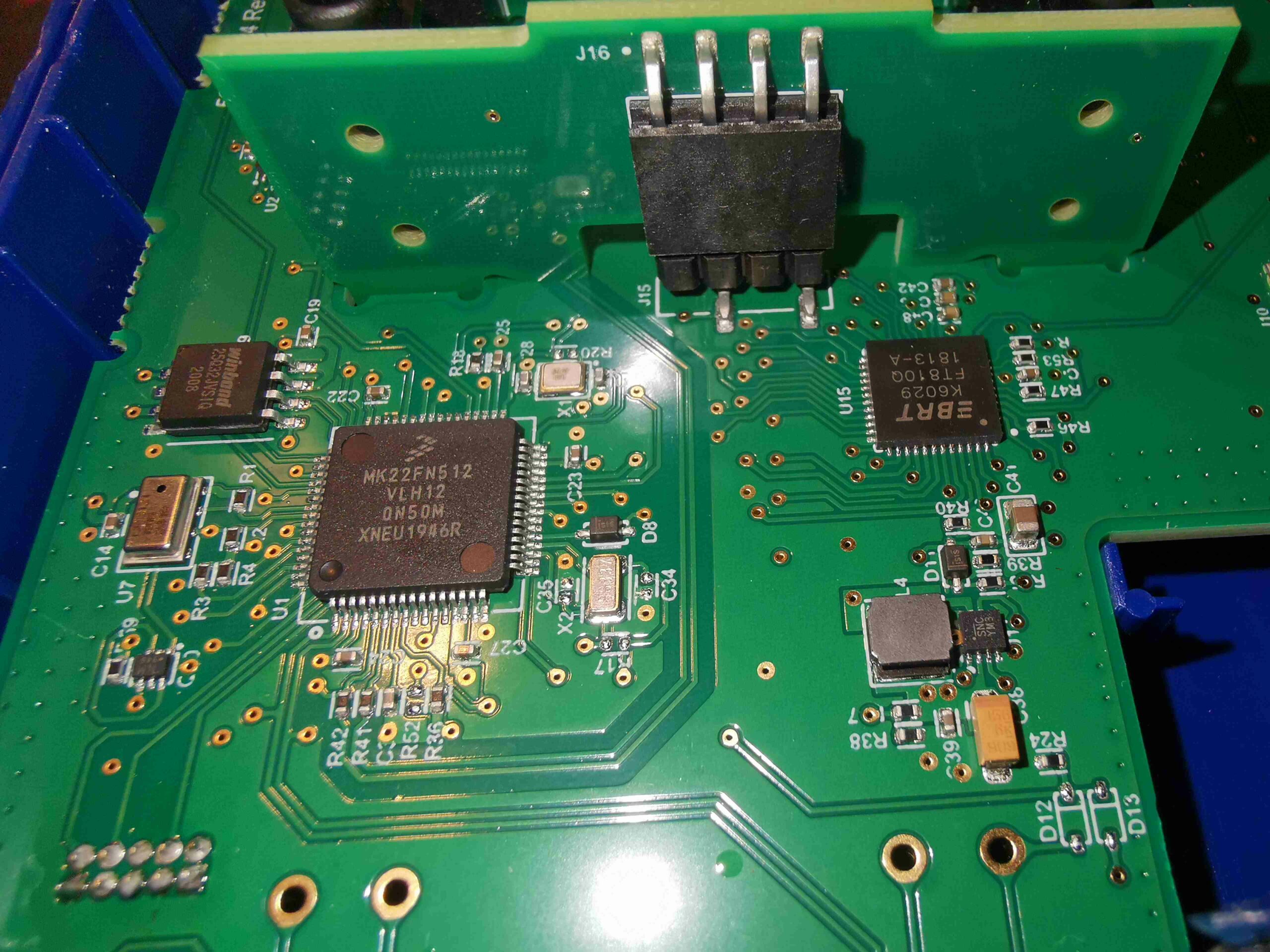
The muscle of the operation here is a Freescale (now NXP) Kinetis K2 Series MK22FN512VLH12 ARM microcontroller. With a Cortex-M4 core at 120MHz, there’s a bit of beef here. The LCD & touch overlay is controlled by a Bridgetek FT810Q Embedded Video Engine. The video controller communicates with the microcontroller via SPI, and the LCD via parallel RGB. There’s some SPI Flash memory up on the left, for log data storage, a Winbond W25Q32JV 32Mbit part. Just under that is a pressure sensor, which I’ve been so far unable to pull a part number off. This is required to assist in calibration of the main pressure transducers.
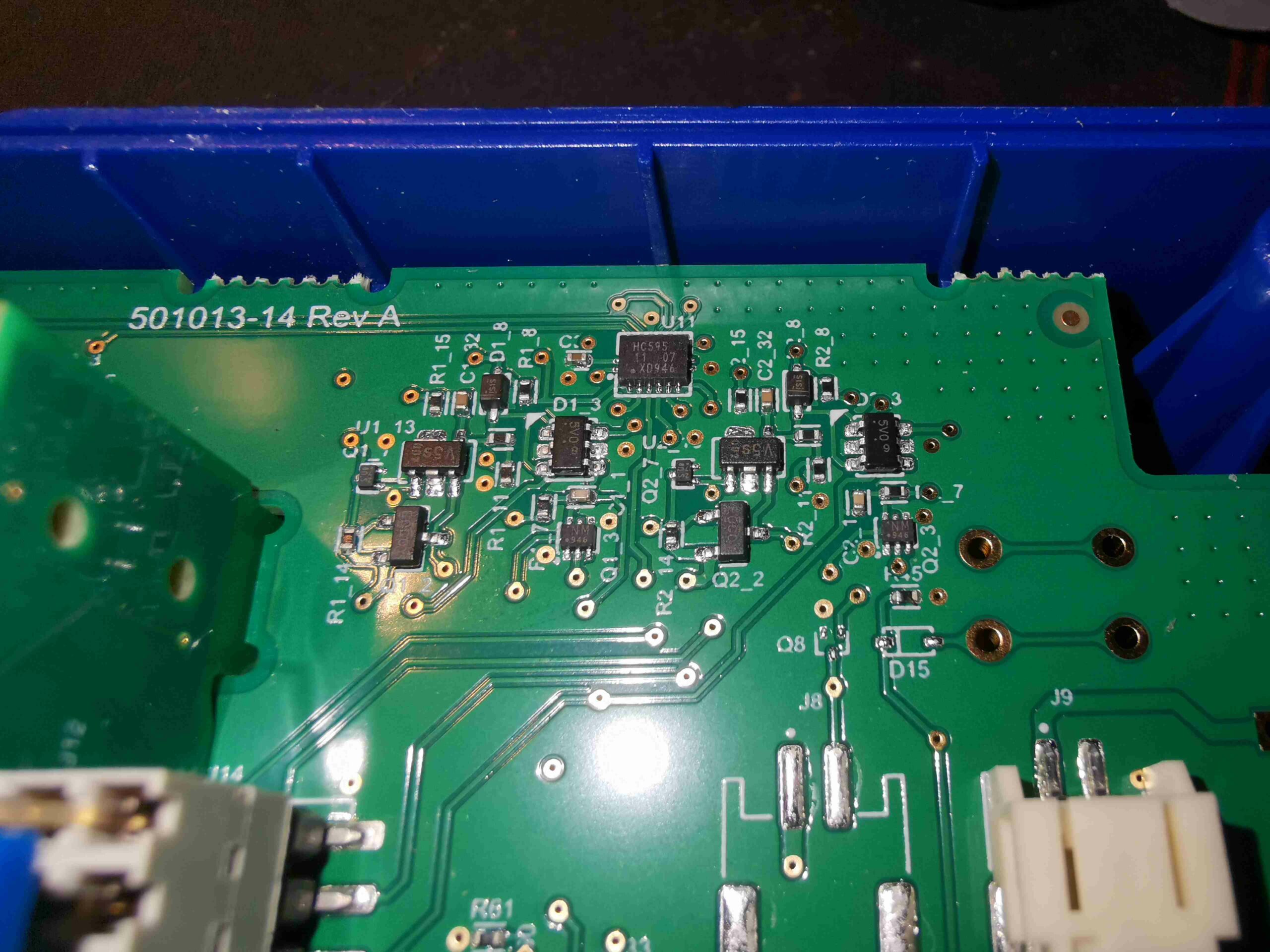
In the top right corner of the board is a 74HC595 shift register, with quite a few discrete transistors & diodes hanging around it. I suspect this is used to switch between two vacuum sensors when both are plugged in – from looking at the waveforms present on the sensor interface, the power does appear to be switched ON/OFF on a single sensor at about 1Hz.
My guess at the moment is that the sensor communications are over I²C, by the 4-wire connection, and the very obvious clock & data line on the connector, but I haven’t yet looked deeply into this.
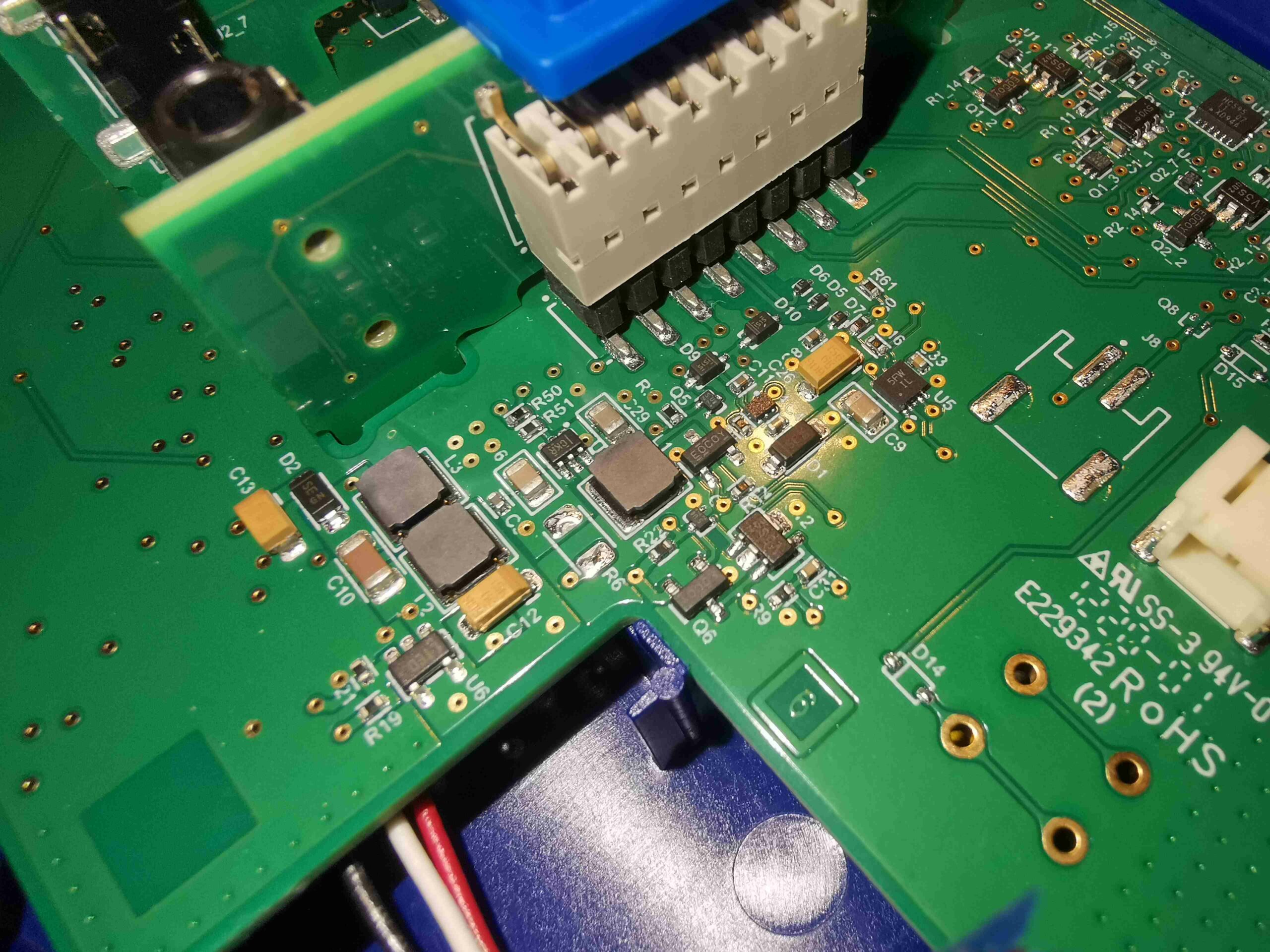
Next to the battery connector (the battery itself is a single LiPo pouch cell, double-sided taped to the front shell, behind the display), are a selection of DC-DC converters, providing all the required voltage rails. No doubt there’s lithium charging control going on here too.
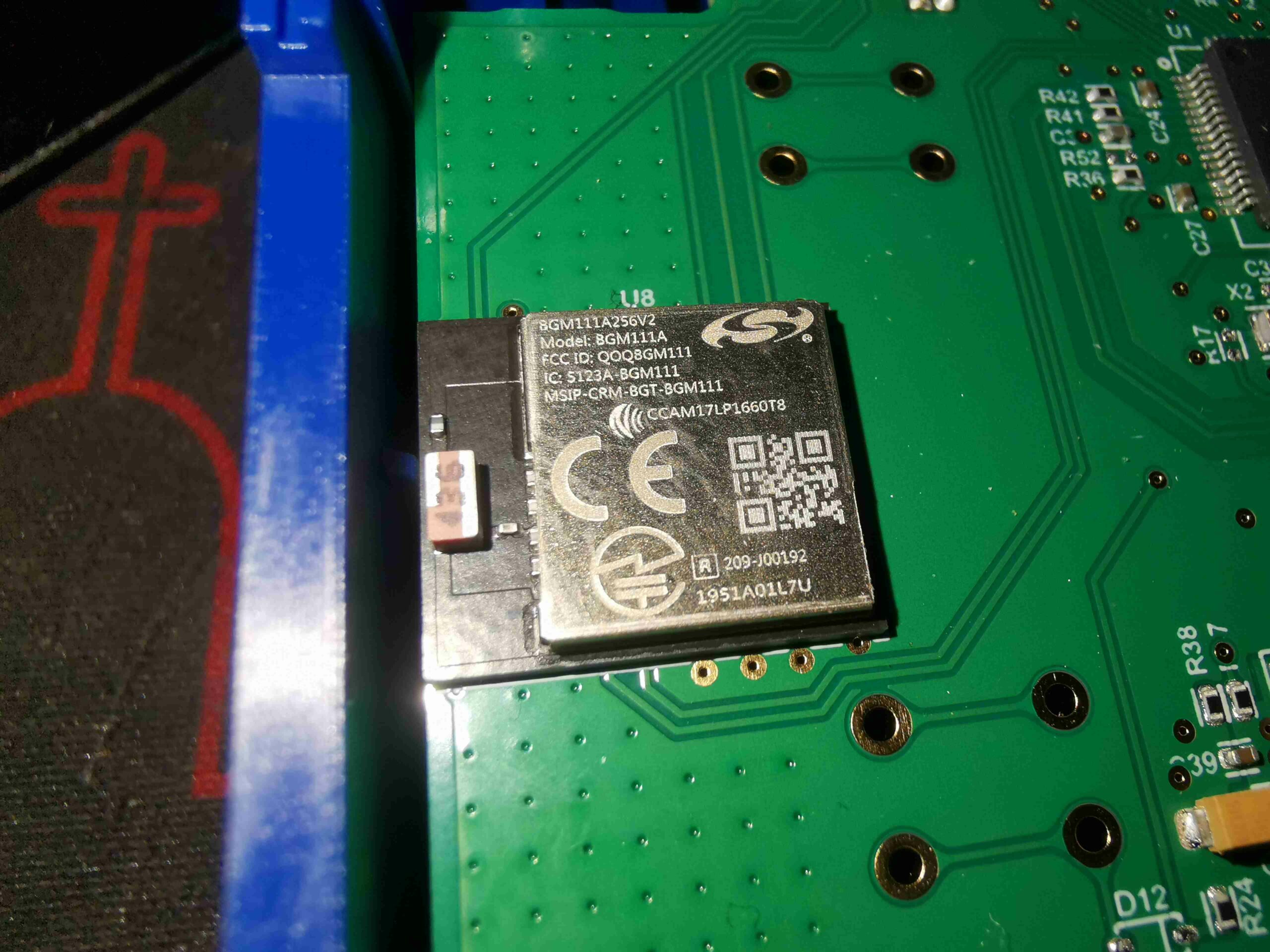
Wireless connectivity is provided for by a Silicon Labs Blue Gecko BGM111A256V2 Bluetooth 4.2 SoC module. These are also fairly powerful parts, with a full ARM Cortex M4 microcontroller hiding inside, clocked at 40MHz. There are as a result two programming headers on this board, in the top left corner, for both this part & the main microcontroller.

Hello, Im a HVAC service tech and i have a set of these gauges but the circuit board is bad. Its not reading the temperature probes.
Do you know where I could purchase a replacement board. Yellow jacket said they dont sell th eboard.
Hi Kristopher – unfortunately I do not know if it’s possible to obtain a replacement PCB – if YellowJacket don’t supply one, then you’re pretty much out of luck unless the existing board can be repaired. It may just be the connections to the sockets on the back of the unit that are faulty, and a simple repair.
Could you not send the manifold to YJ for a full repair service?
Cheers
Hey Kris (it’d be REALLY awkward if u were my boss, Kris Moore hahaha). I use the same gauges at work and had a couple issues with mine. 1st issue was the same as yours. I only use 1 temp clamp at a time now, because I already returned a whole set (warranty). The issue with the clamps aren’t the socket or the board, it’s actually the male 3.5mm trs jack. I clipped the end of mine about 3in away from the jack, to solder a new one on. Then, I realized I had to look at how it was wired. So I carefully put a blade to the molding on the jack, and took that layer off. Turns out, they barely put THE SLIGHTEST amount of solder on these jacks. The shielding popped off the “sleeve”. I wound up reusing the clipped off end… Soldered the shield back on, added a bit more solder for the tip and ring wires, then I made the cable to a 90° through the slit I made in the molding, put some marine grade 4-1 shrink tube on it, and forced it to keep its 90. Now when I pull it out, I’m not tugging on those solder joints. Been working for months like that now!
My 2nd issue (somewhat related) was my charging port. This time, it was on the board. When I opened up the gauges, right away I saw my port was hanging on by 1 finger! I took an old device with the same port in it, unsoldered them both with a rework station, clean up the solder from the board, stuck the “new” port on, and soldered that in. That’s when I noticed that it was never soldered on correctly!! On the other side of the board, there should be 4 holes for the legs (ground) of the port. That side SHOULD HAVE SOLDER COMING THROUGH! But it never did.. so I added some there. It’s literally made that way, so the port has strength and stability. They only soldered 1 side of the board! I then noticed that they did this to all the components (even the female TRS jacks) that have “legs” for this very purpose. At this point, I was over messing with it, so I didn’t add any solder to the TRS jacks.. but everything works and the world is safe
Ive used these for almost 6 years now and they have recently started loosing charge very quickly and only seem to recharge to about 70% is there a battery that can be replaced
My charging port fell out! How can I reattach or any suggestions?