Since I got my new DeWalt combi drill, I needed a way to charge the batteries without having to resort to sticking blade terminals into the pack connectors – I didn’t purchase the branded charger, mainly due to cost. I also have a very capable multi-chemistry charger that handles multi-cell lithium packs with no issues, so I saw no need to replicate things. This little gadget was ordered just for it’s main pack connector; I can then use this to make up a charger adaptor cable. What this normally does is allow the use of DeWalt XR battery packs to charge mobile devices via 5v USB outputs, so there’s going to be some kind of DC-DC converter in here. There’s also a “charge level indicator” built in, which doesn’t actually do anything sensible – even on a flat battery pack, showing a single LED on it’s charge indicator shows the full 3 LEDs on this unit.
The remaining feature is a trio of white LEDs to function as a torch, but it’s less than stellar in the brightness department. Given that there’s not much in the way of control inside the battery packs themselves, I reckon this unit could actually overdischarge a pack, causing damage.
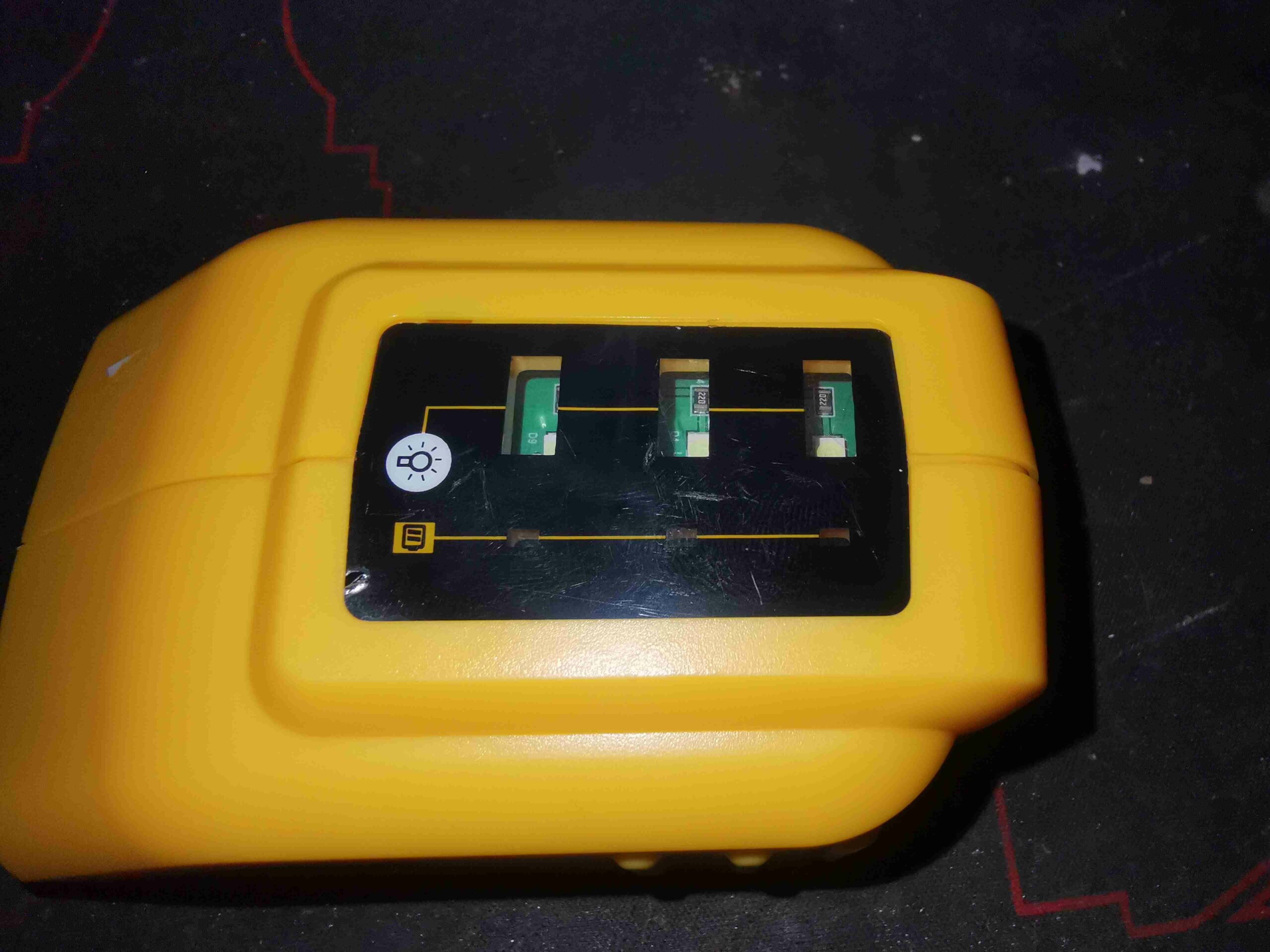
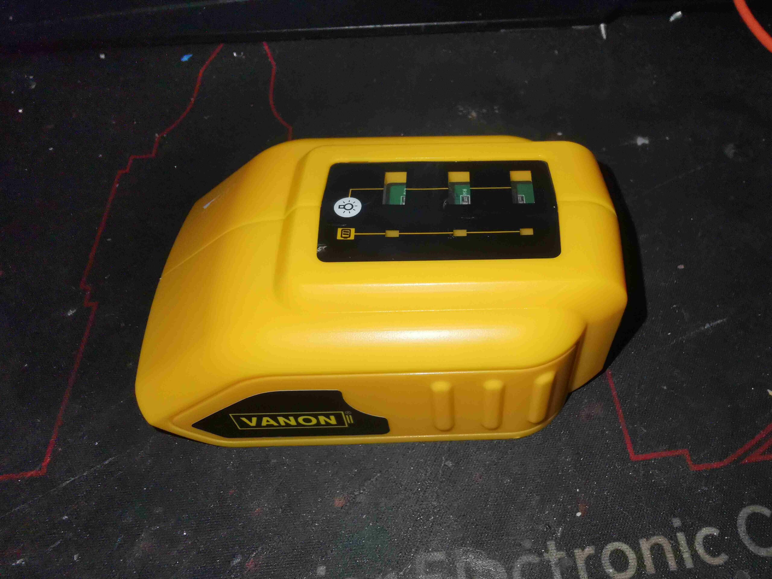
The top of the unit has a large label with windows in for the various LEDs, and a pad covering the tactile switch to operate the torch function.
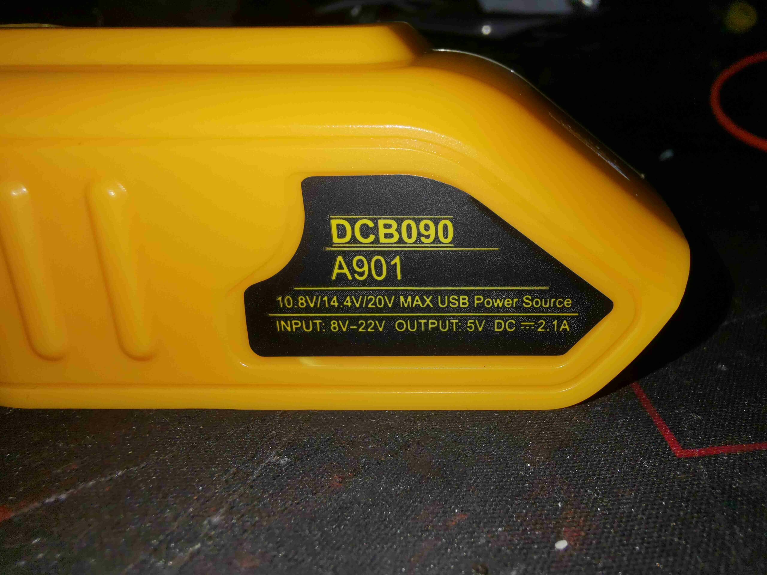
The label on the side indicates the unit will operate down to 10.8v, good for the 3S packs, as well as the 18/20V packs.
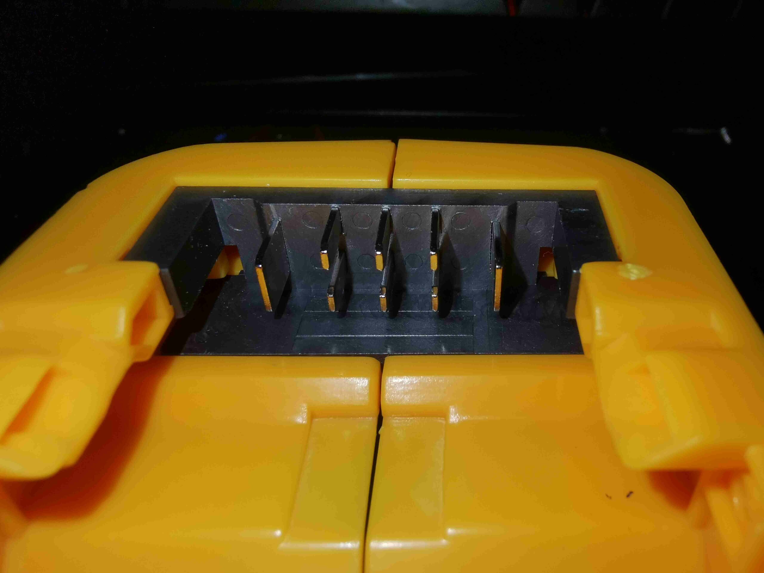
Here’s what I was after – the battery pack connector. This has the full compliment of pins for all the balance taps too.
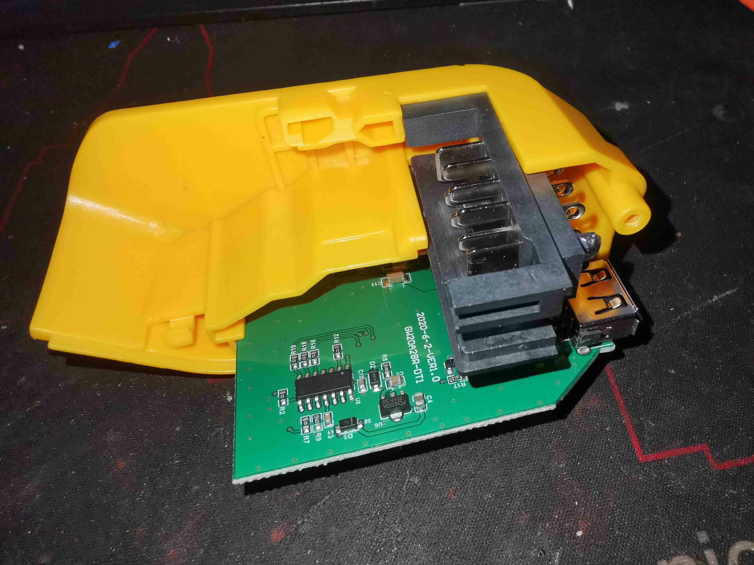
Removing a label, and a single screw gives access to the internals. There’s not much in here apart from a large PCB, with a few components.
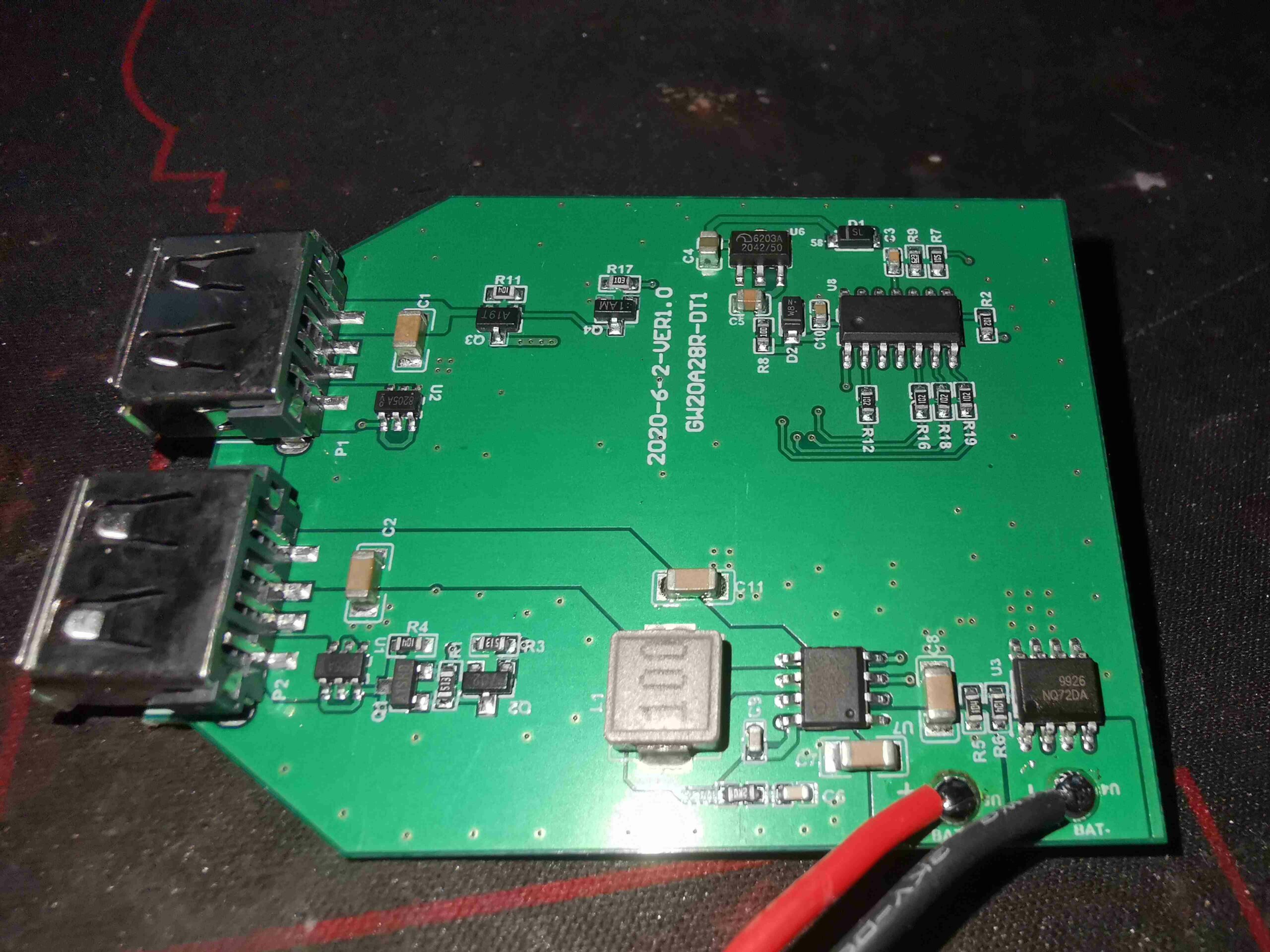
The PCB is pretty sparse. There’s a microcontroller in the top right corner that does the torch LED switching, and the “battery indicator LEDs”. This is completely unmarked, which is very common now for Chinese microcontrollers. The only way I’m identifying this one is via a decap operation on the IC!
The USB ports have MOSFETs in their negative pin paths, probably to switch off the ports if they’re overloaded. The data pins are bridged together on one port, and connected to the DC-DC converter on the other port.
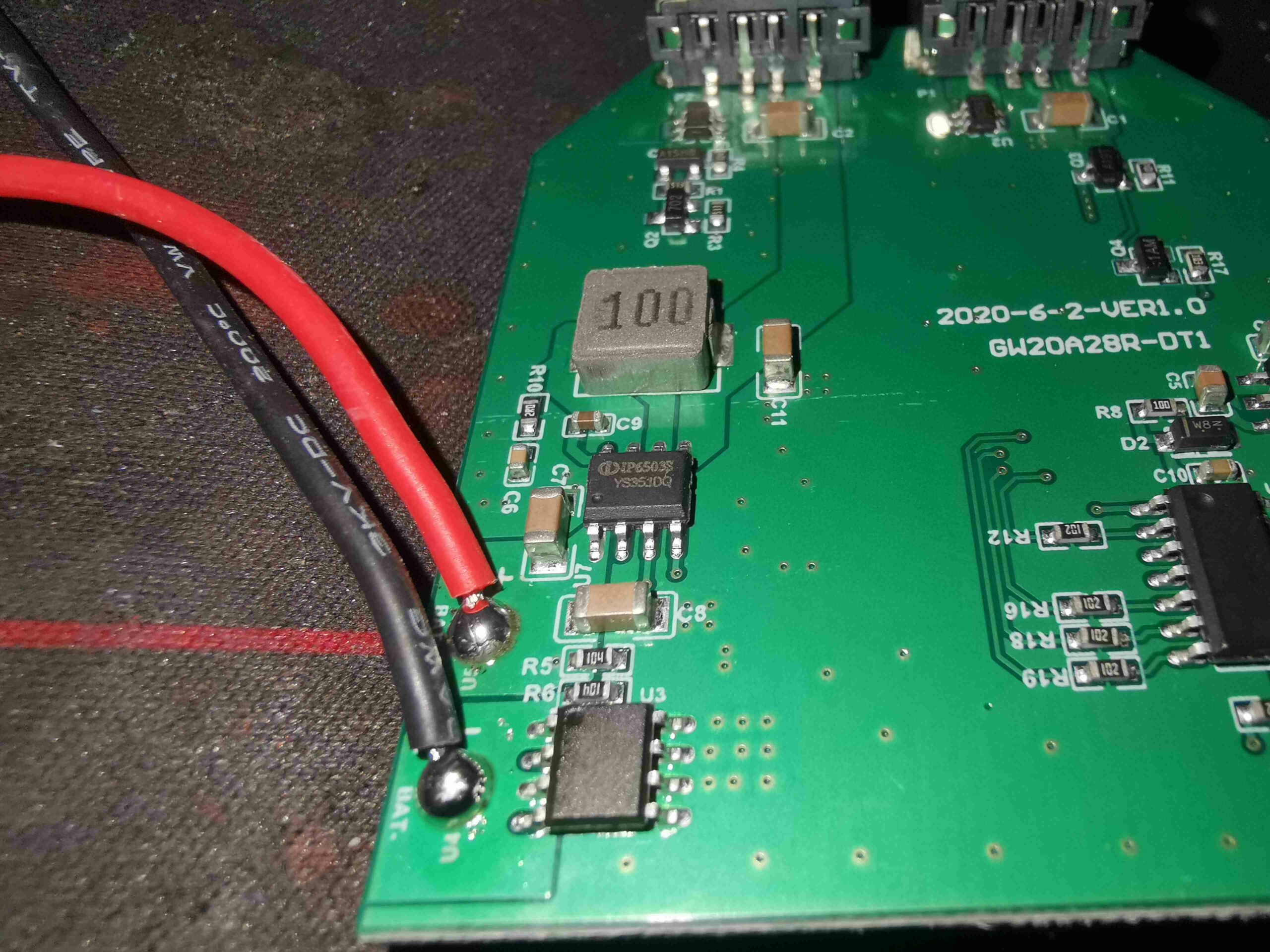
The main DC-DC converter IC is in the bottom right corner of the board, next to the input pins. This is an IP6503S multi-protocol USB charging converter, with a 24W power limit. This explains why the data pins of one of the USB ports is connected back here – it’s doing some communications with the connected device for fast charging. Chinese datasheet below.
