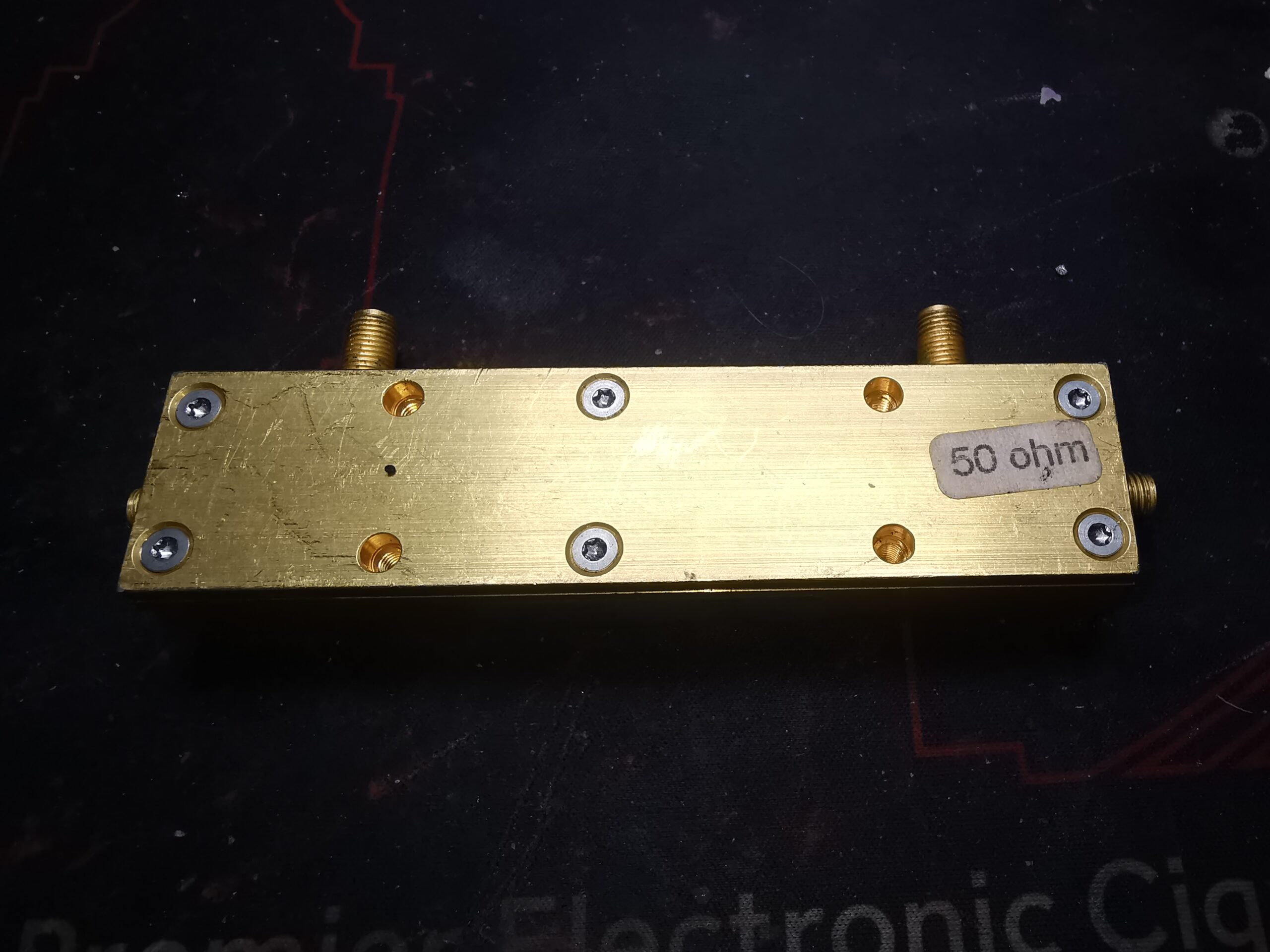
Time for some more RF component teardowns, here’s a very high quality Directional Coupler from HP, I believe this was part of a Vector Network Analyser at some stage. The main body appears to be made of Brass, but the entire unit looks like it’s Gold plated – the shine is far too good to be just Brass! Connections are via SMA connectors.
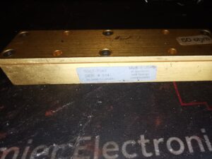
There isn’t much on the label to explain what the specifications are unfortunately. Nothing that can’t be found out with a quick look on a VNA though.
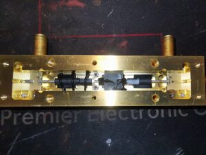
After removing the 6 Torx screws securing the top cap of the coupler, the internal components are revealed. There is no RF gasket or seal on the top cover, and relies on flat machining for an RF seal.
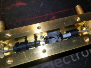
The internal construction of this unit is a little different from what I’ve seen before in directional couplers. The arrangement is usually parallel copper tracks on a suitable RF substrate, but in this case, HP have used a very small diameter Coaxial cable, covered with ferrite sleeves on the outer shield. The large square block in the middle is rubber, and may just be to stabilise the assembly. It may also be loaded with ferrite powder to give some RF properties too.
The ferrite cores are secured in place with beads of black silicone, again probably to prevent movement under vibration.
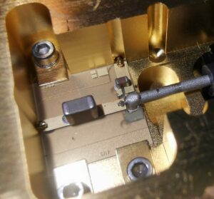
The input of this coupler is AC coupled via a capacitor, and then fed into the centre core of the Coax. The forward power output pin, visible at the top of the track, is coupled to the centre core of the coax by a tiny carbon track making up a resistor, via another ceramic capacitor. The track is more directly coupled via another carbon trace to the outer shield of the Coax. I believe this coupler is damaged, as the carbon trace that goes via the capacitor has a break in the centre, but the coupler does seemingly still work.
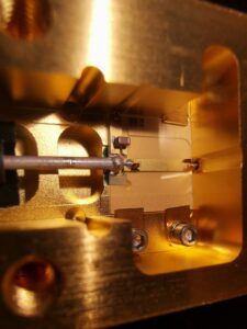
The other end of the coupler is very similar, although with no main line coupling capacitor, it’s direct fed to the SMA here. The reverse power output is connected the same way as the other, with a network. The carbon trace here though doesn’t have a break.
