In an effort to reduce the level of superflous stock I have in the workshop, I’ve set up a new store to sell off some of these parts & modules. It can be found over at store.experimental-engineering.co.uk. I’m still building the inventory, and new items are being added all the time. The money raised will go towards new posts & projects.
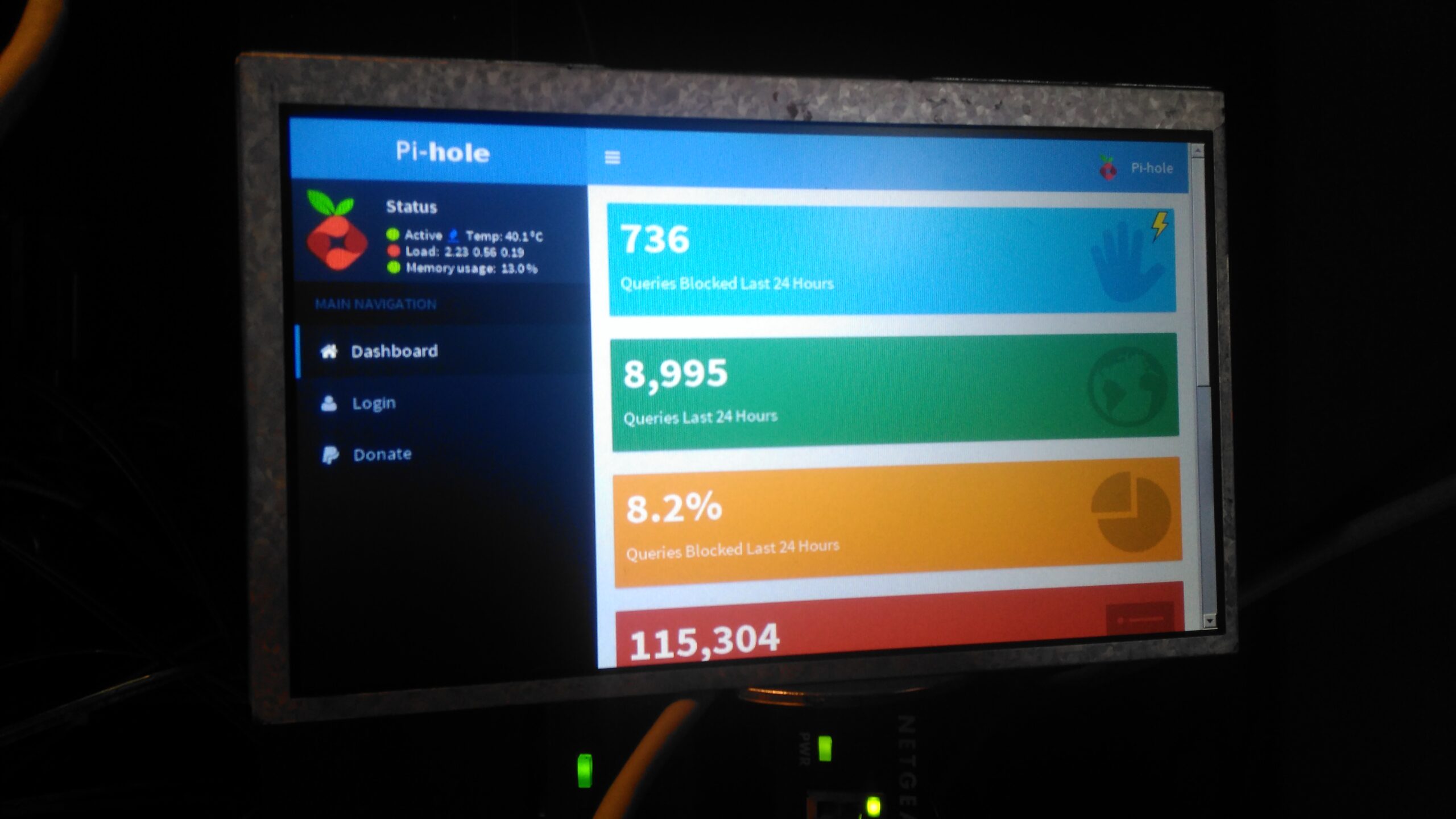
On my home network I have a system running PiHole – a DNS server that blocks all unwanted traffic, such as ads. Since I have an official Pi LCD with a broken touch panel, I decided to use the bare LCD as a status display for PiHole.
This requires some extra packages installing onto the base system after PiHole is installed & configured, and the interface automatically starts on bootup. I used the latest Raspbian Jessie Minimal image for this system, and ran everything over a SSH connection.
First thing, get the required packages installed onto the Pi:
Once these are installed, it’s time to configure the startup script for Midori to display the status page. Create StartMidori.sh in /home/pi and fill with the following:
#!/bin/sh export DISPLAY=:0
xset -dpms
xset s off
xset s noblank
unclutter &
matchbox-window-manager &
midori -e Fullscreen -a http://127.0.0.1/admin/
This script disables all power management on the system to keep the LCD on, starts unclutter to hide the mouse pointer and finally starts the Matchbox Window Manager to run Midori, which itself is set to fullscreen mode, and the URL of the admin panel is provided.
The next step is to test, give the script executable permissions, and run the script:
Once this is run, the LCD should come to life after a short delay with the PiHole stats screen. Close the test & return to the terminal by hitting CTRL+C.
Now the Pi can be configured to autorun this script on boot, the first thing to do here is to enable autologin on the console. This can be done with raspi-config, select Option 3 (Boot Options), then Option B1 (Desktop/CLI), then Option B2 (Console Autologin). When prompted to reboot, select No, as we’ll be finishing off the config before we reboot the system.
The next file to edit is /etc/rc.local, add the command to start the status browser up:
#!/bin/sh -e
#
# rc.local
#
# This script is executed at the end of each multiuser runlevel.
# Make sure that the script will "exit 0" on success or any other
# value on error.
#
# In order to enable or disable this script just change the execution
# bits.
#
# By default this script does nothing.

# Print the IP address
_IP=$(hostname -I) || true
if [ "$_IP" ]; then
  printf "My IP address is %s\n" "$_IP"
fi
sudo xinit /home/pi/StartMidori.sh &
exit 0
Here I’ve added in the command just above “exit 0”. This will start the browser as the last thing on bootup. The Pi can now be rebooted, and the status display should start on boot!
So it’s time to get the propulsion system underway for the trolley, a pair of wheelchair motors were sourced for this, from HacMan. Since I don’t know how many hours are on these units, or how they’ve been treated in the past, I’m going to do a full service on them to ensure reliability. I decided on wheelchair motors due to their extreme ruggedness & heavily built components – this project when complete is going to weigh in at about 150kg!
I suspected something was amiss with one of the motors from running them under no load: the left hand wheelchair motor was heating up to the point of being too hot to touch, so this one at the very least needed some investigation.
Motor Disassembly & Assessment
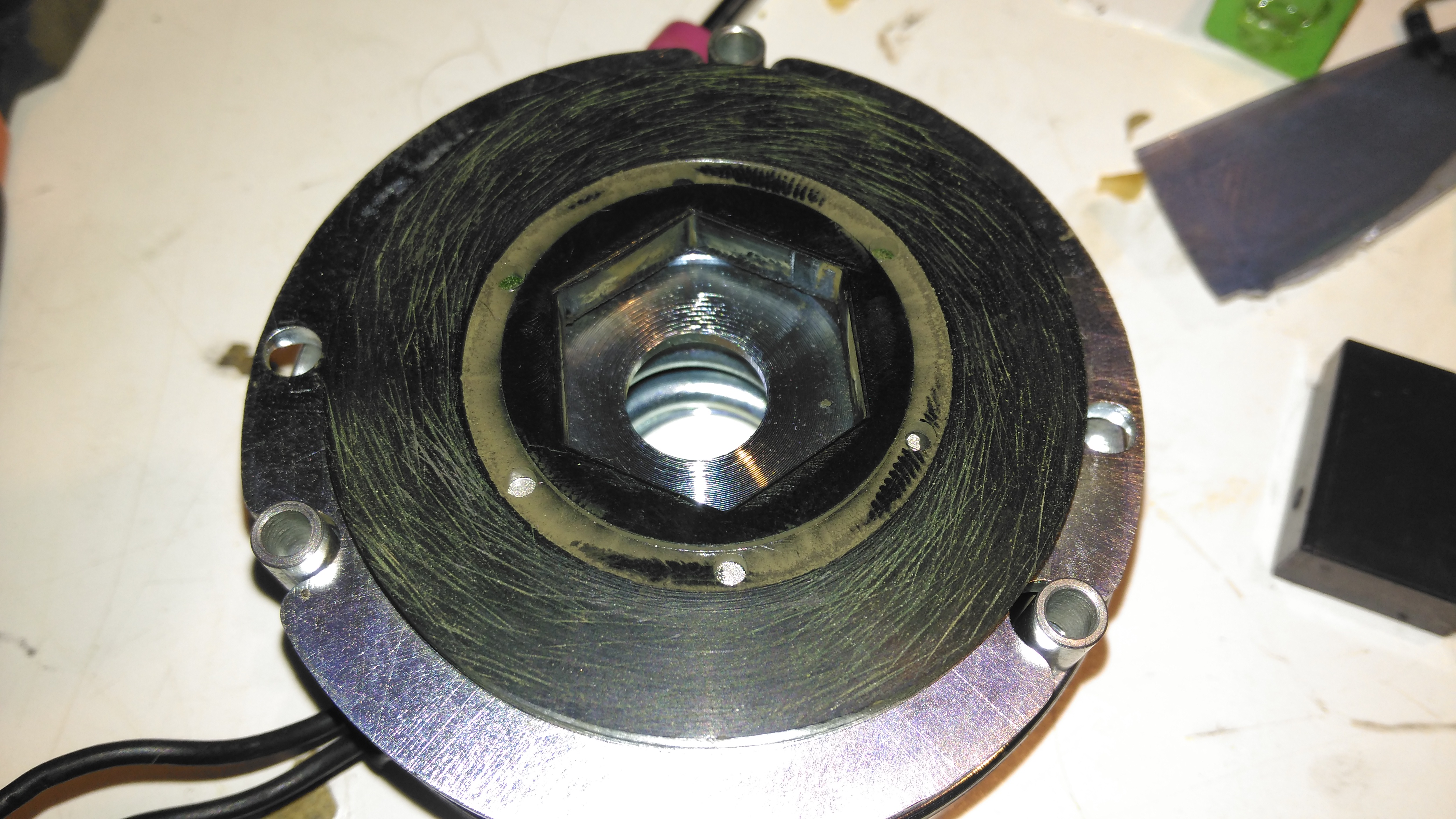
Rear Cover Removed
With the back cover removed from the motor the electromagnetic brake is revealed. This engages when power is removed to stop the motor freewheeling, which even though it’s a wormdrive box, it will do readily if backdriven.
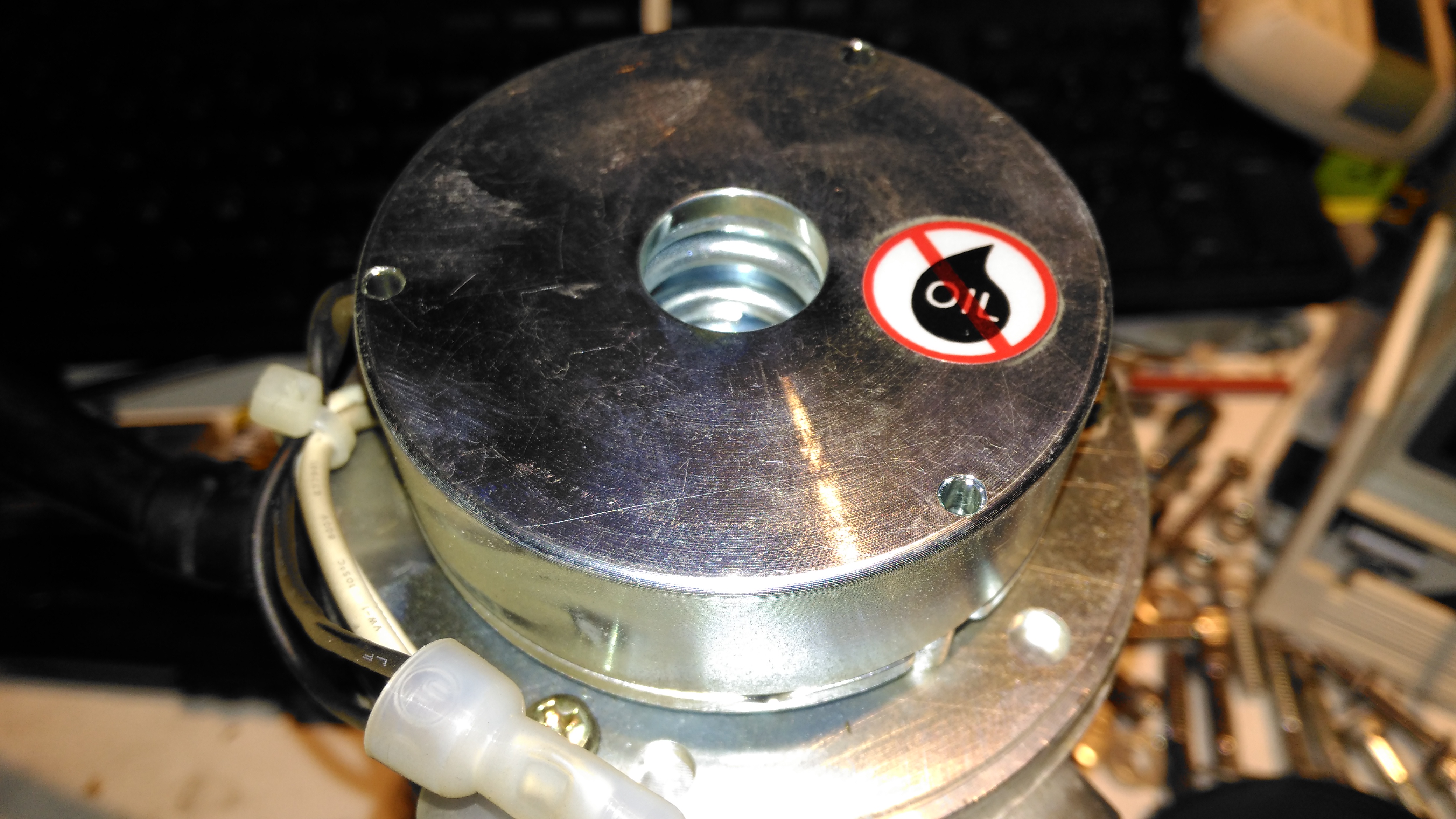
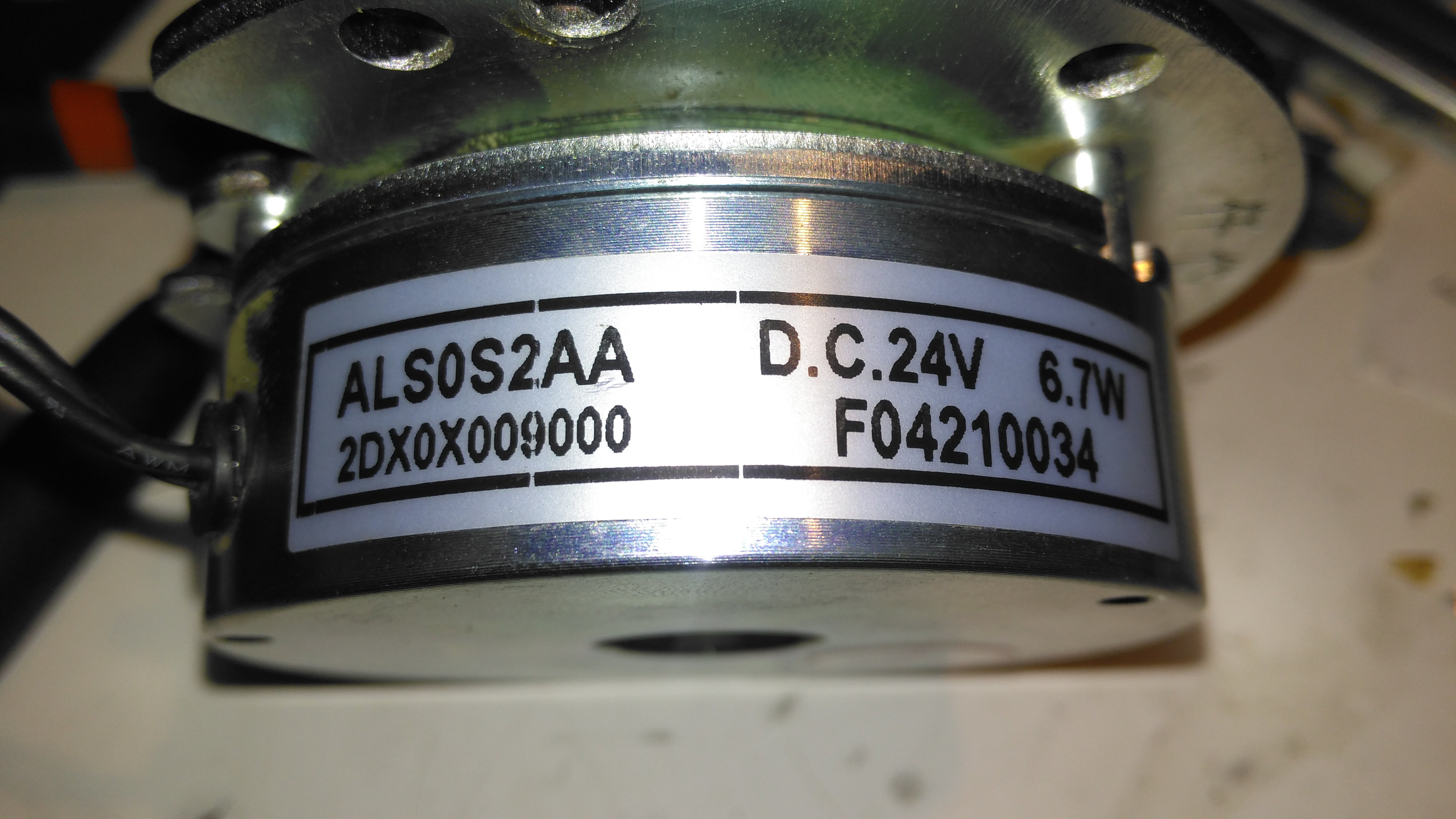
Electromagnetic Brake Assembly
The brake is rated 6.7W at 24v DC.
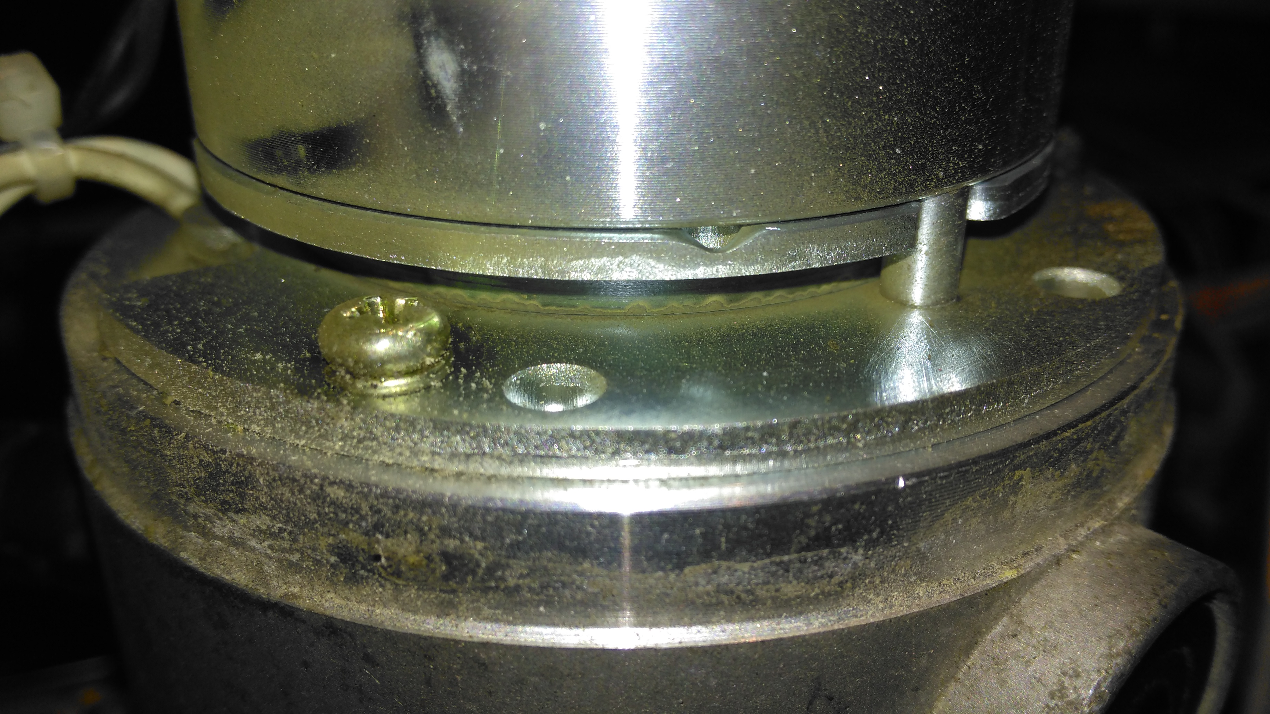
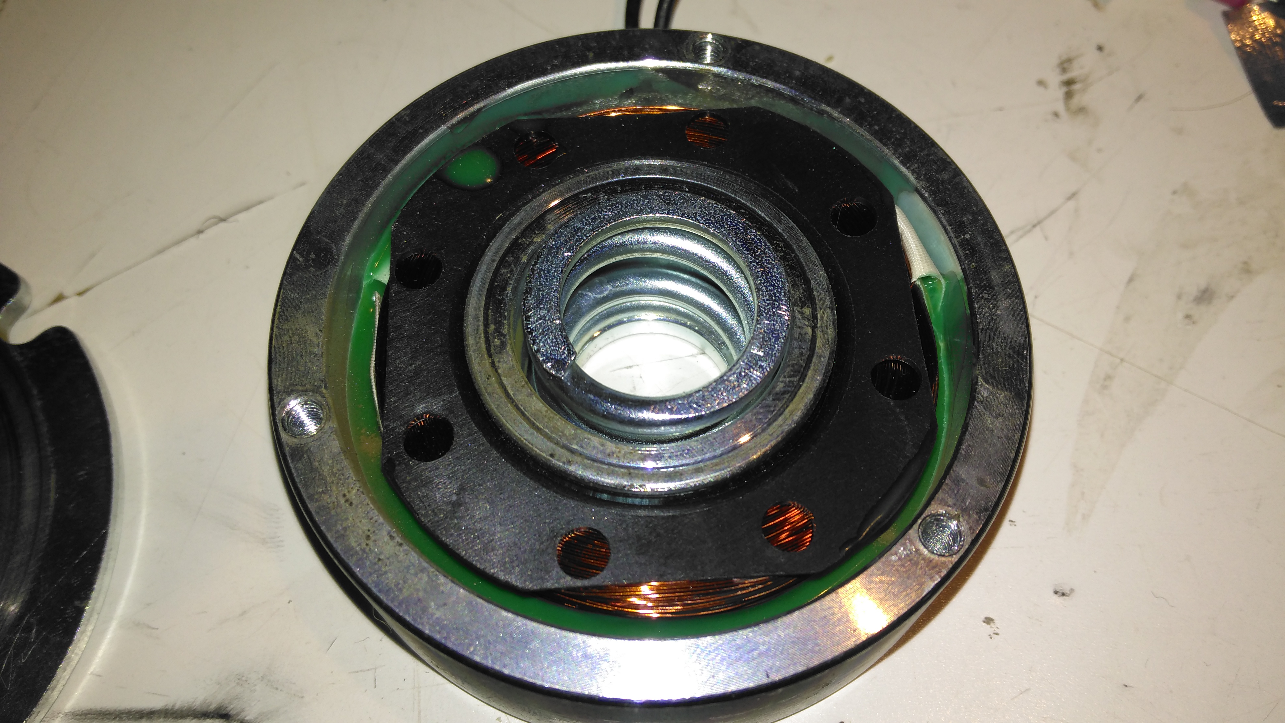
Brake Disc
The brake disc is just visible between the plates of the brake here, with some green dust worn off the disc. When power is applied, the top disc, just under the magnet on top, is pulled upward against spring pressure away from the brake disc, which is attached to the motor armature.
Brake Disc
Here’s the brake disc, removed from the motor. There’s only a little wear here, as I’d expect – these brakes don’t engage until the motors have come to a complete stop.
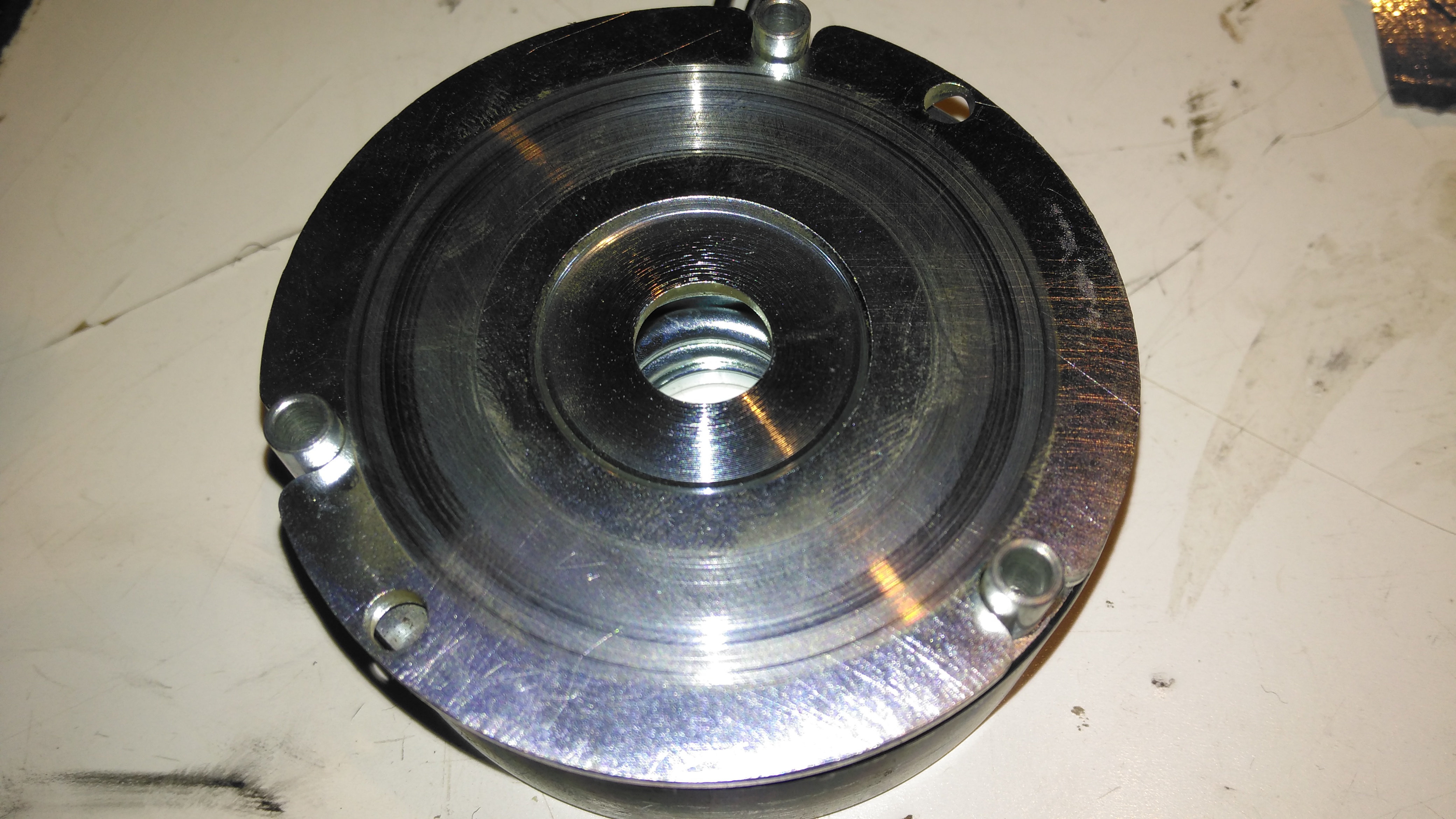
Brake Actuator
The steel disc above the magnet acts as one of the friction surfaces of the brake.
Brake Solenoid
Finally, the solenoid is at the back, partially potted in resin. The strong coil spring in the centre applies the brakes when power is disconnected.
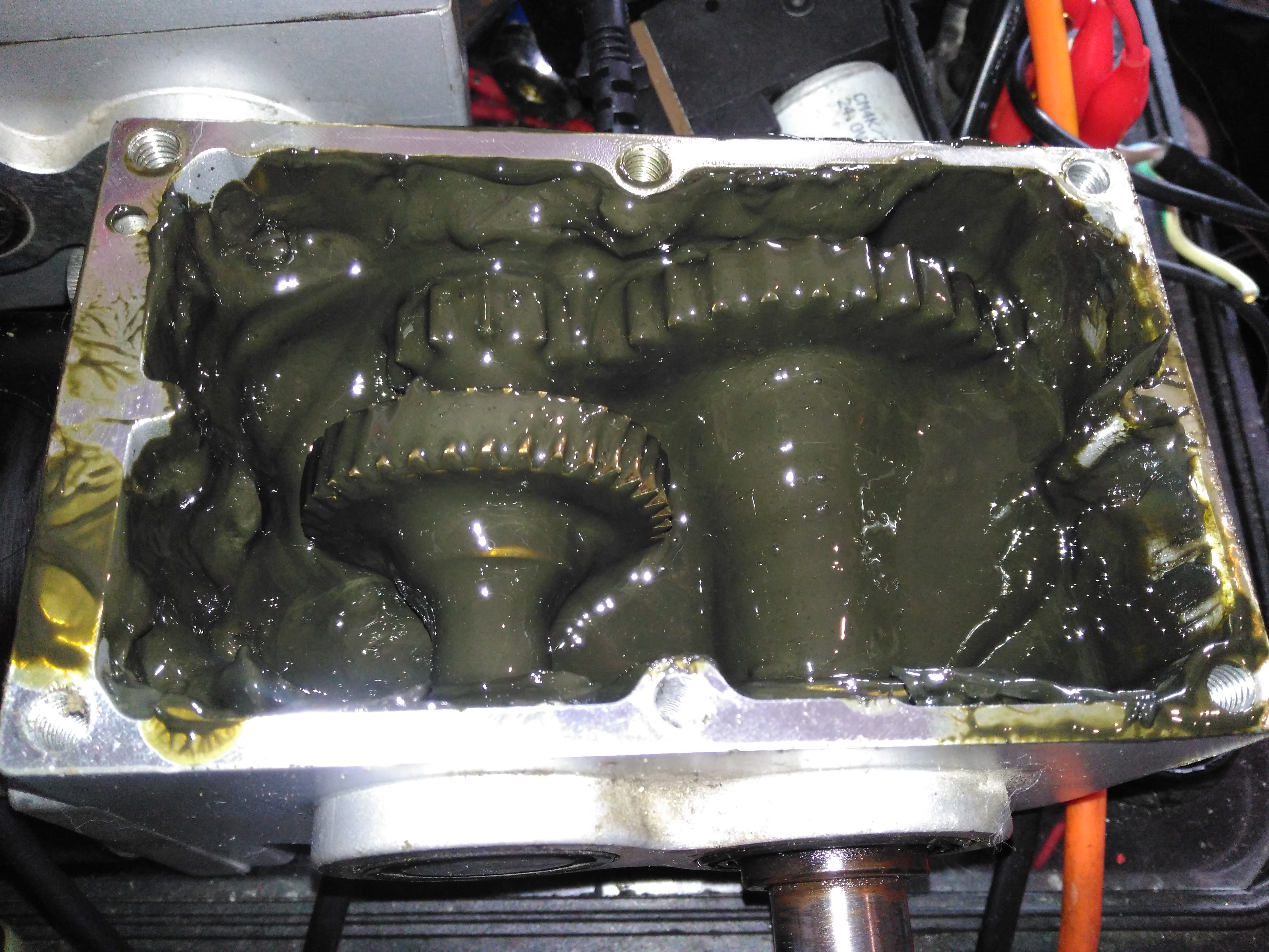
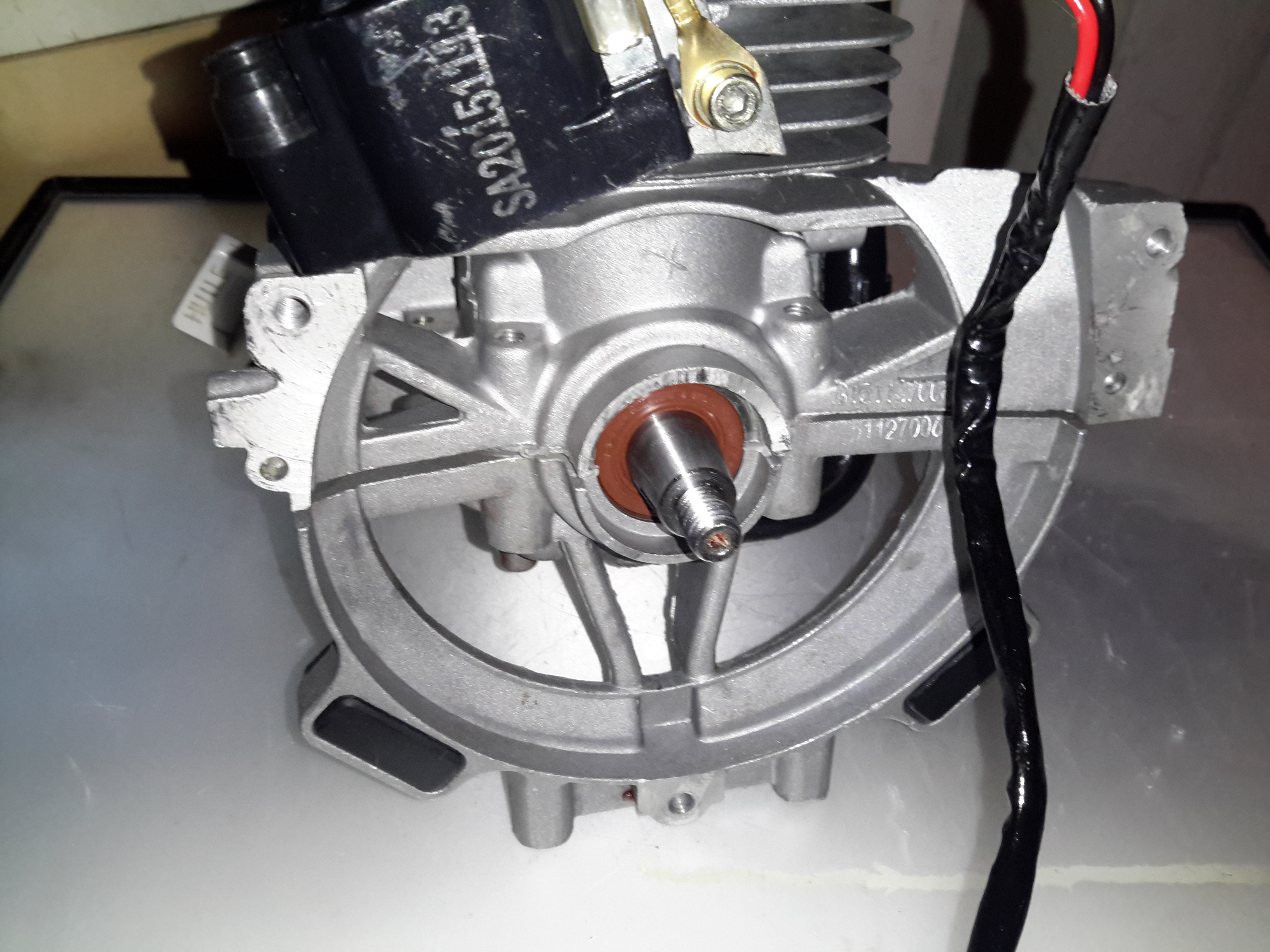
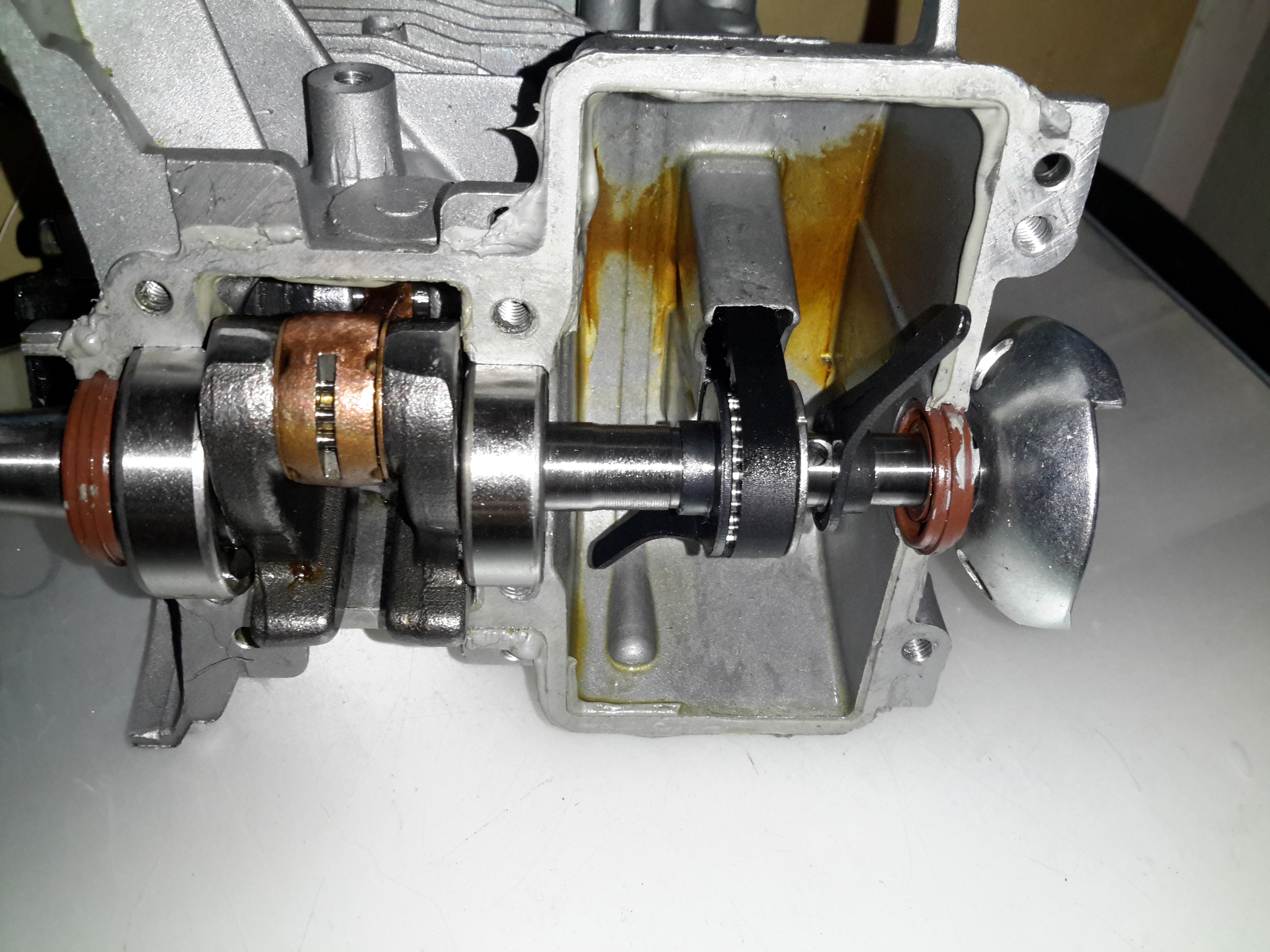
Gearbox Grok
Removing the top of the gearbox reveals the state of the internals – There’s no wear at all on the gearset, but the lubricant is totally manky. The external oil seals have been leaking for some time, letting water in and grease out. The emulsified result is revolting! These gearboxes have a wormdrive first stage, the worm gear is underneath the left hand gearset. Steel spur gears then do the final gearing to the output shaft. The output gear is splined onto the output, and can slide along the shaft out of mesh – this is the freewheel clutch mechanism. At the moment it’s all obscured by the disgusting lubricant.
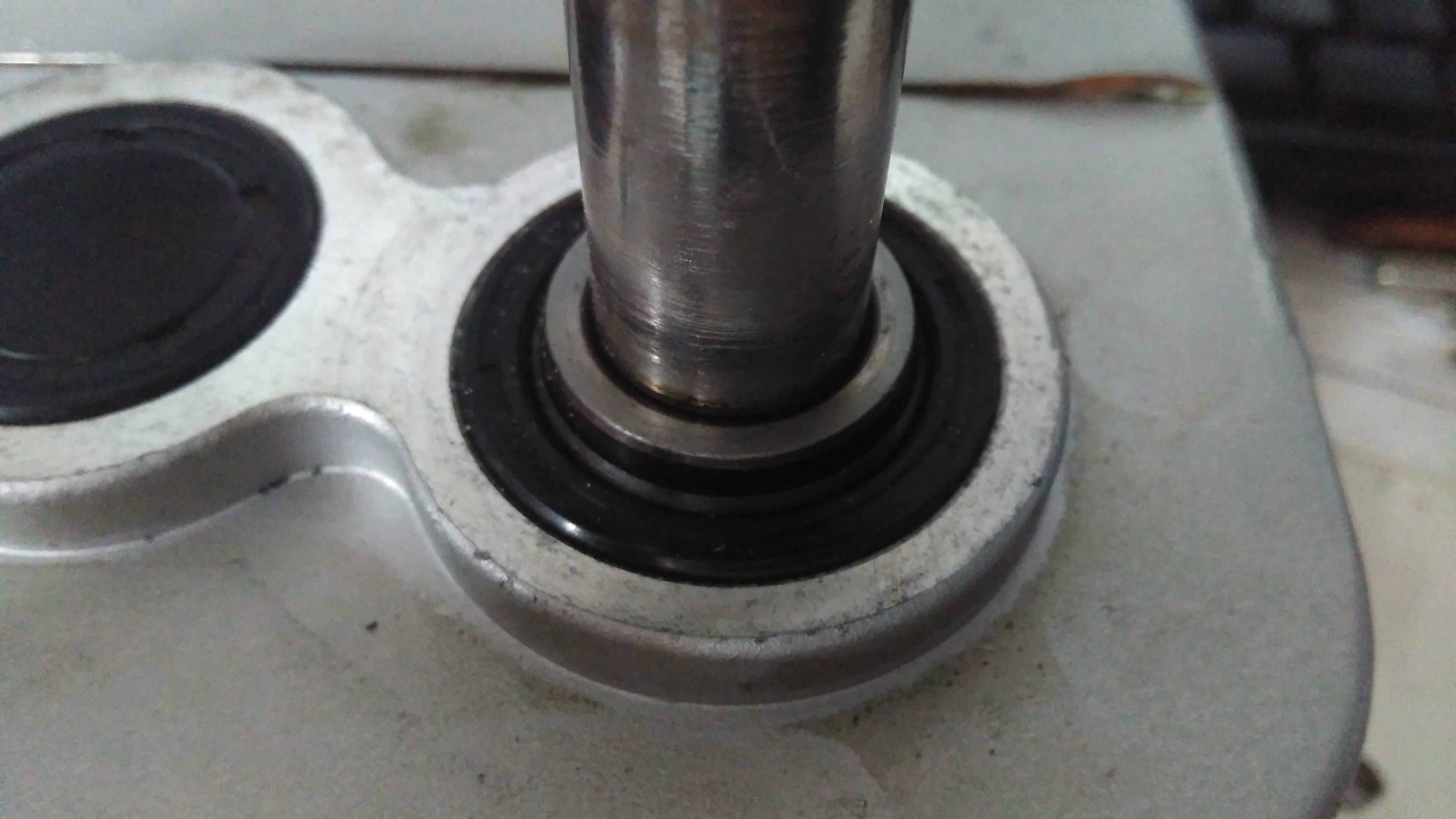
Input Shaft Seal
Here’s the failed seal on the left hand gearbox, the face damage was done by petrol immersion to clean everything up. (The seal is already compromised, so I’m not fussed about solvents eating the remaining rubber). The motor shaft is joined to the gearbox input by a rubber coupling.
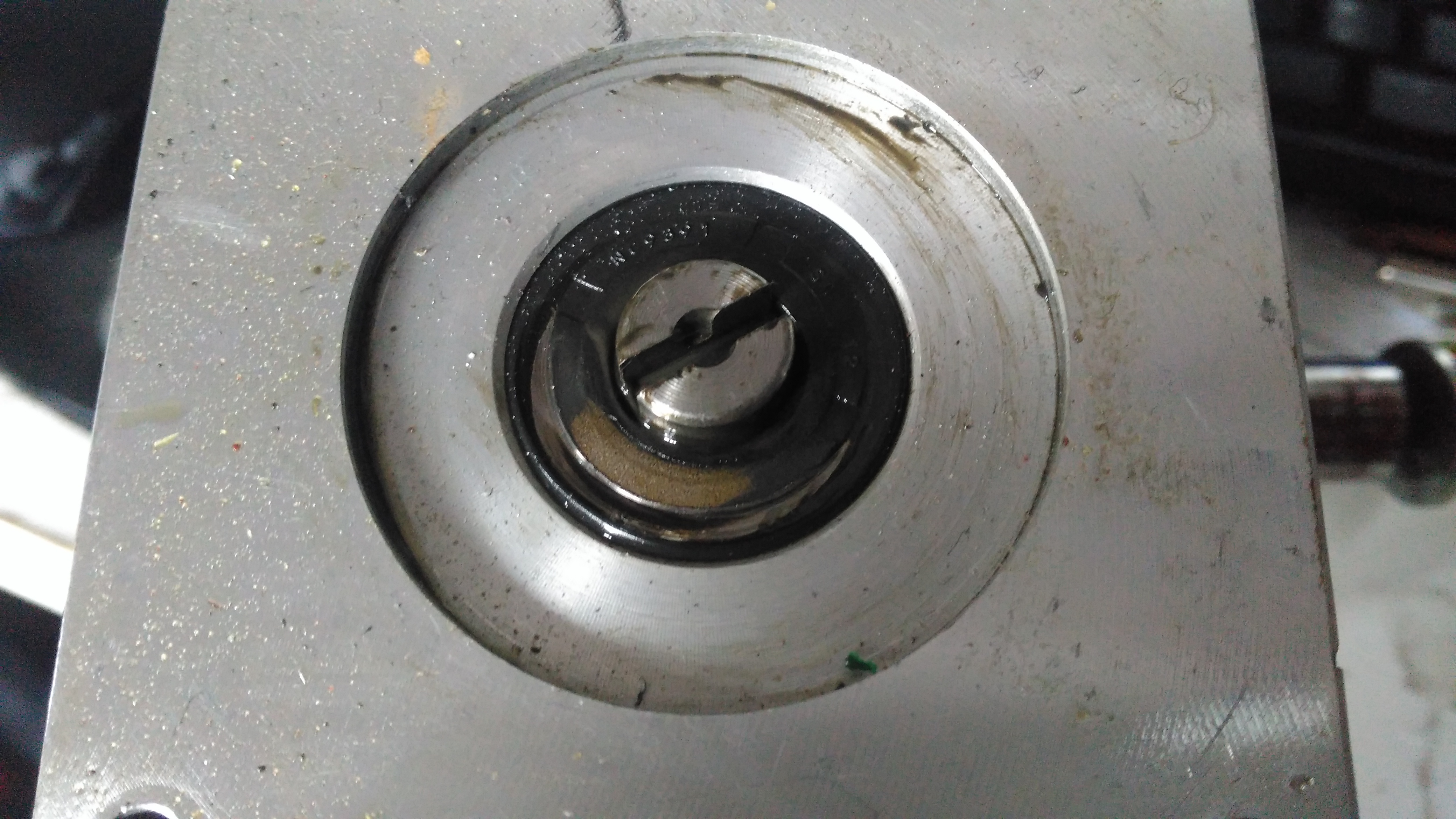
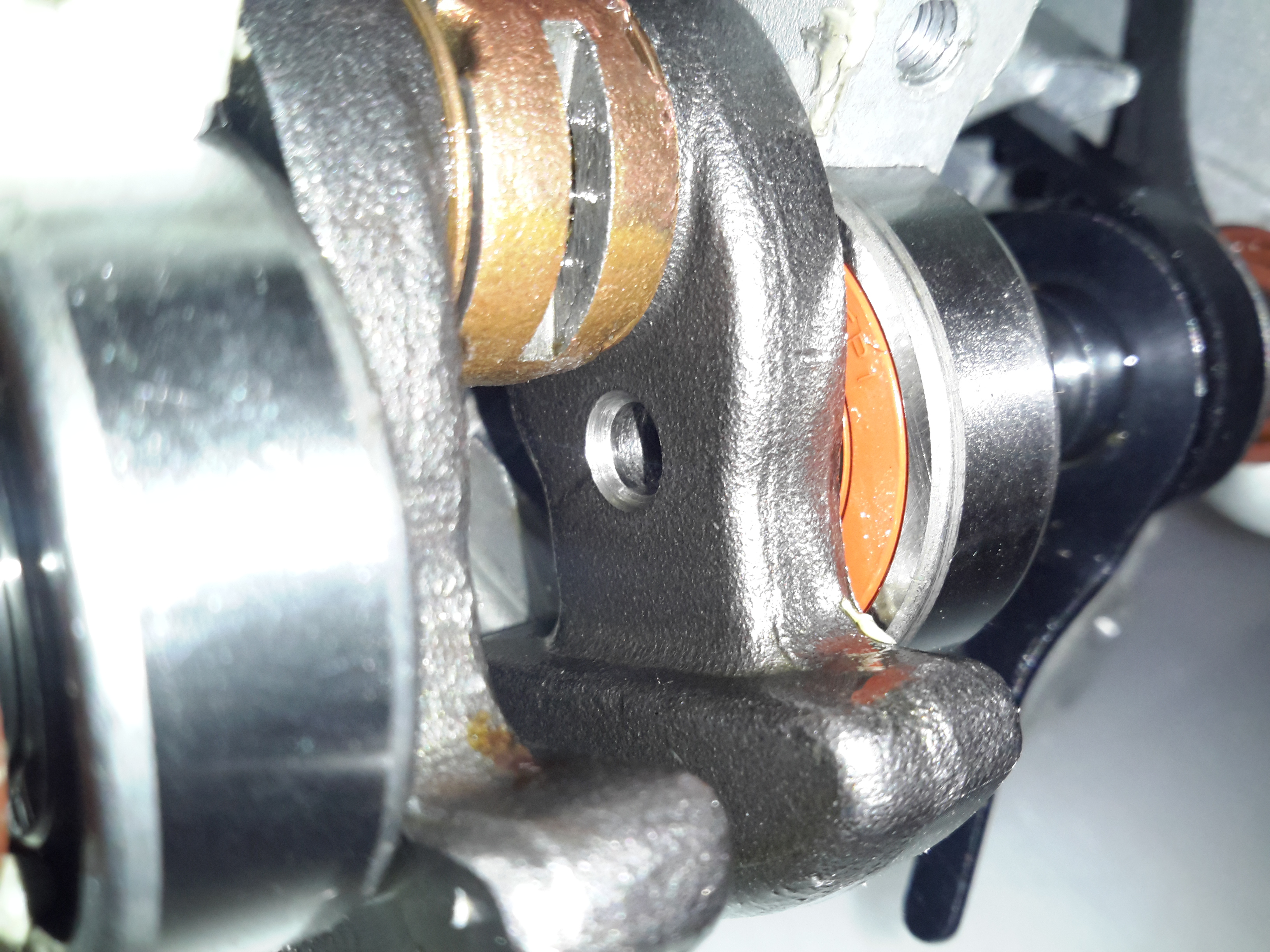
Output Shaft Seal
The output shaft seals seem to be still OK, there has been some seepage past the collar that the shaft rides in, but nothing more. This can be resealed with some Loctite bearing sealant. The sleeve is held into the gearbox by the wheel hub when in operation, but this doesn’t seal the gap unfortunately. I don’t know why the manufacturer didn’t just machine the shaft to that larger diameter, instead of using an extra sleeve to accommodate the seal.
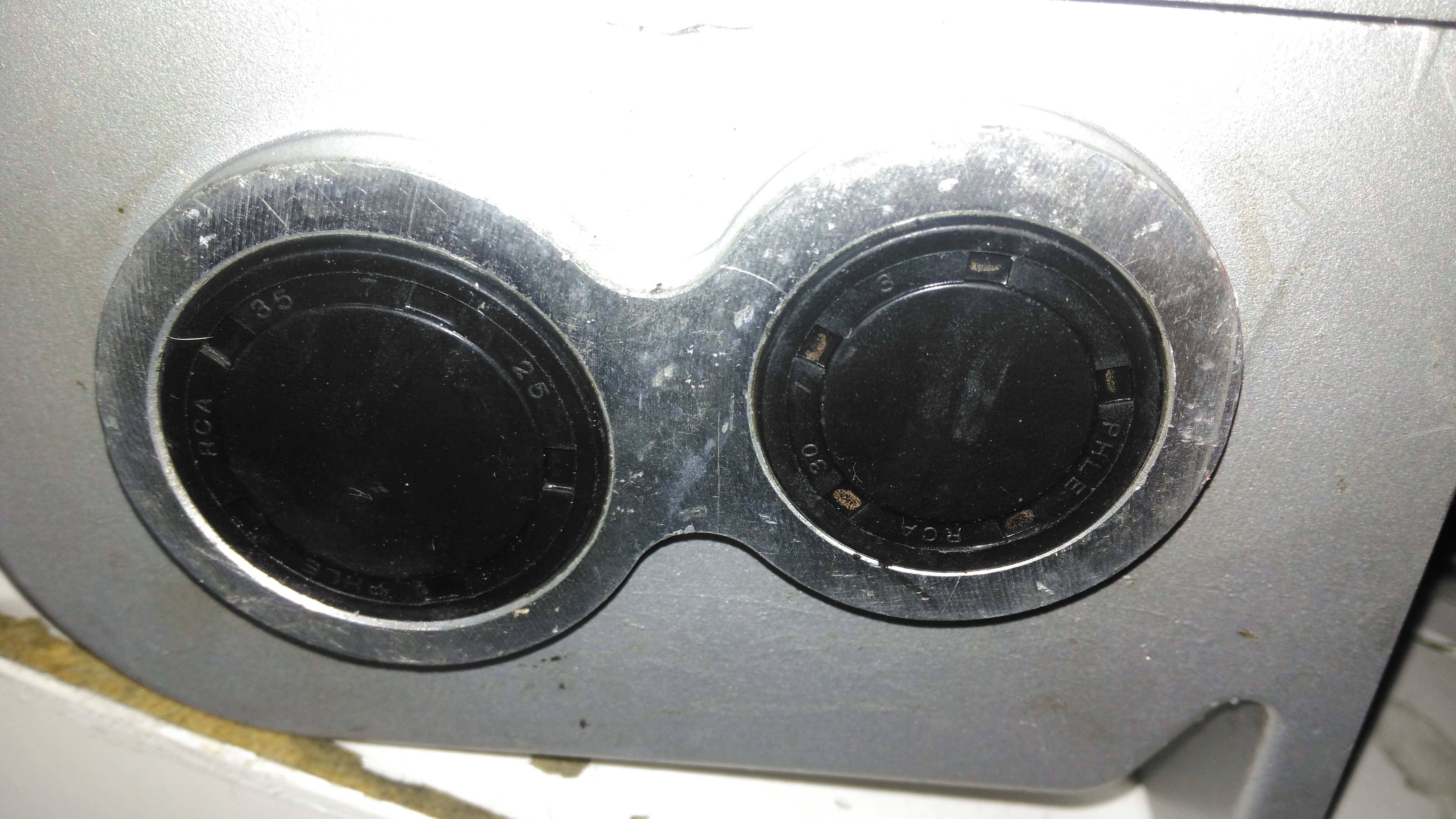
Bore Seals
The bore seals covering the ends of the shafts are also fine, which is a good thing, since I can’t seem to find replacements for these anywhere. The input shaft seals will be replaced on both gearboxes though.
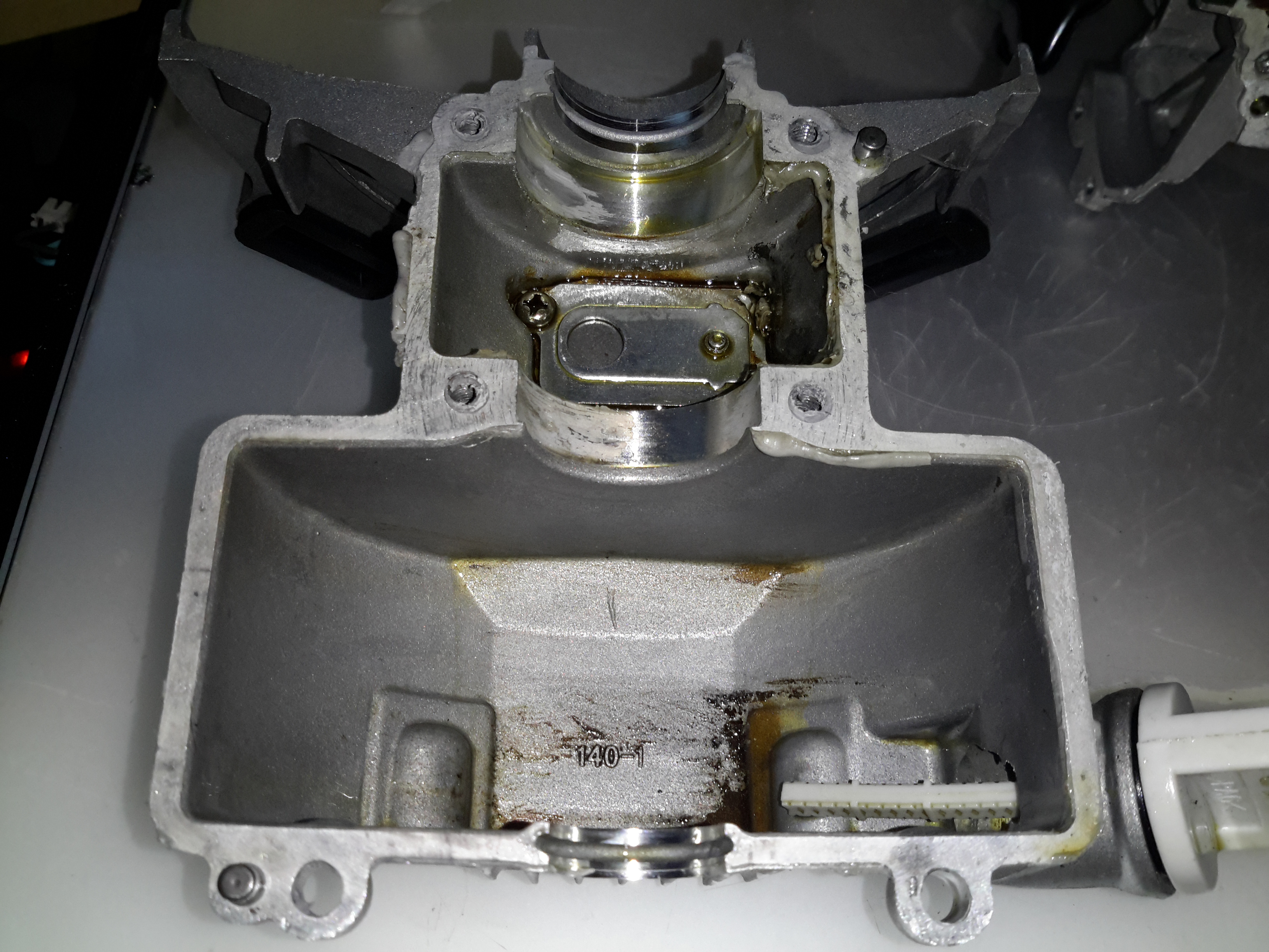
Motor Contamination
The oil seal must have been leaking for a long while! This is the gearbox end of the wheelchair motor frame, completely clogged with grease. Luckily only a small amount has made it down past the armature to the brushgear.
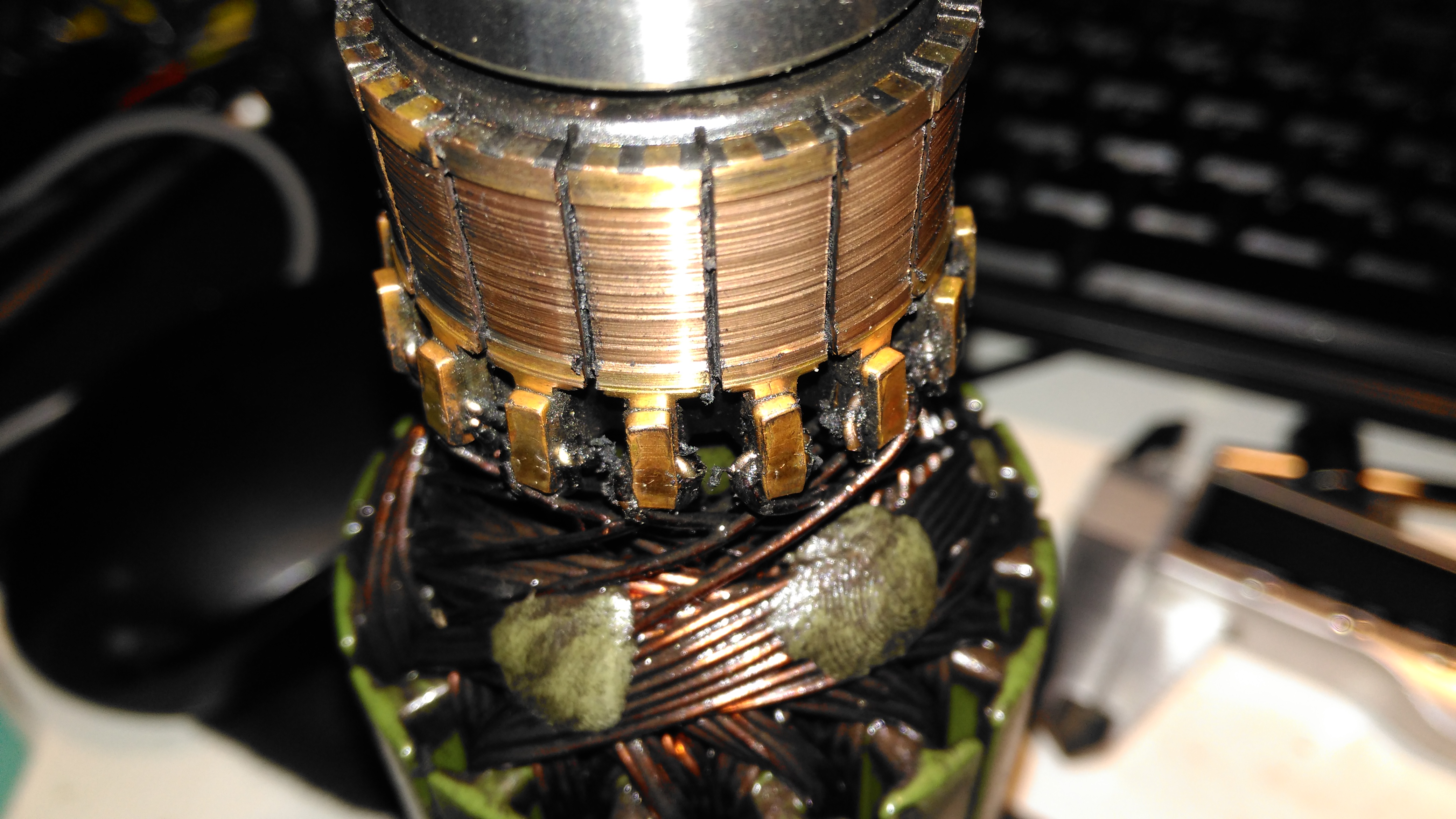
Damaged Commutator
The commutator of this motor is badly damaged, and the brushes are very worn. This has been caused by the gearbox oil seal failing, and contaminating the motor internals with lubricant. The undercut between the segments is all but gone – filled with an abrasive mixture of brush dust, copper dust & old lubricant. Some repair work will be required here.
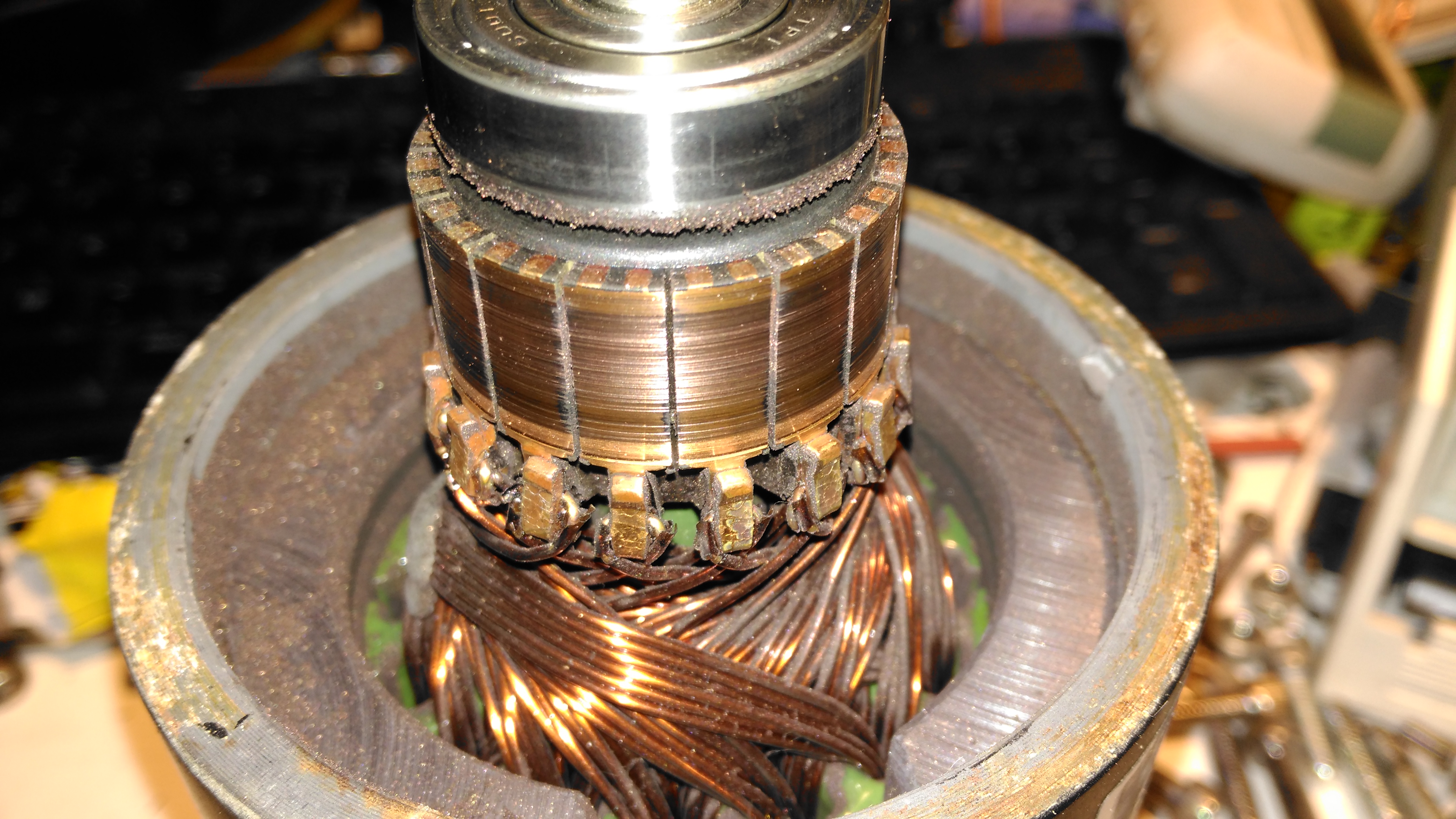
Second Motor
Here’s the brushgear removed from the second wheelchair motor, this one looks much more normal, and there’s not as much wear on the brushes or the commutator. Just the usual coating of brush dust.
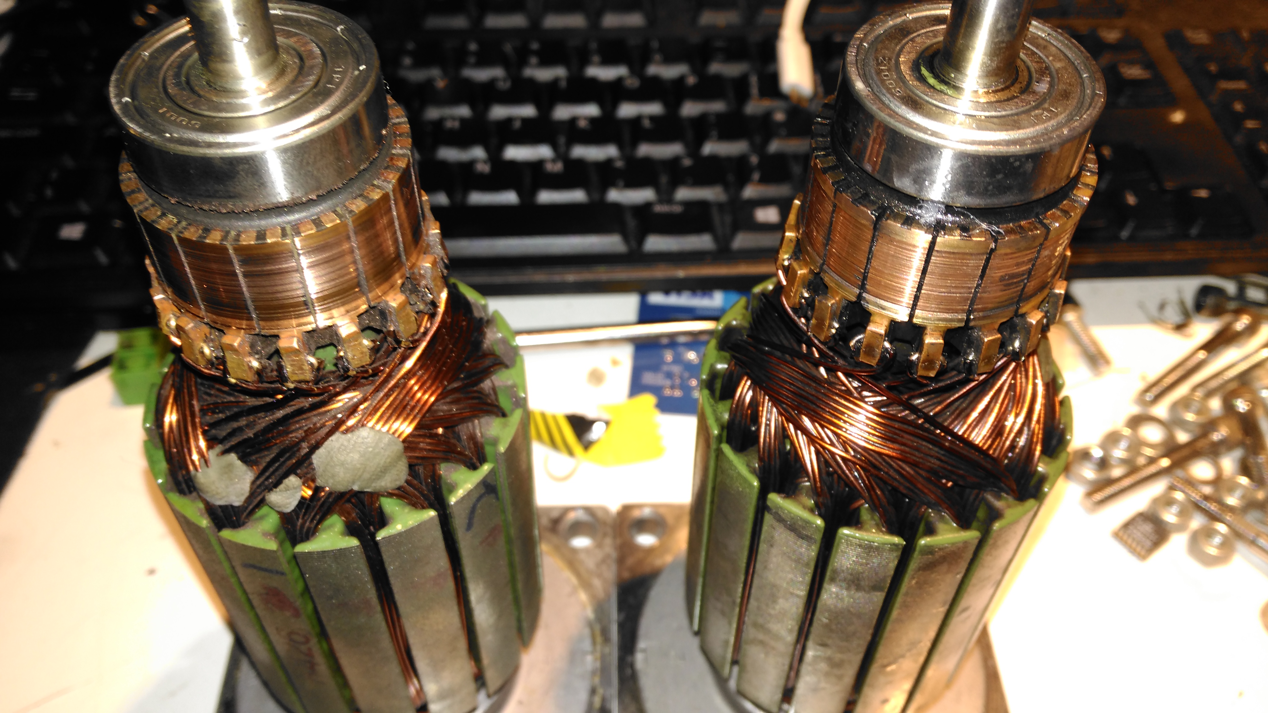
Armatures
Here’s both armatures together, with the contaminated one on the right, after some cleaning to remove most of the greasy old grok & brush dust from everything. The windings on the damaged left hand wheelchair motor haven’t darkened, which I would expect from severe overheating damage, so I’m hoping this armature is OK, and won’t require a rewind. Using an ohmmeter on these windings doesn’t tell me much – there’s only 7 turns of 0.86mm (20AWG) magnet wire in each coil, so they read as a dead short anyway. There was some leakage between the windings and the core before I cleaned things up – this was in the high (28+) megohms range, but this seems to have cleared now I’ve given things a real good cleaning.
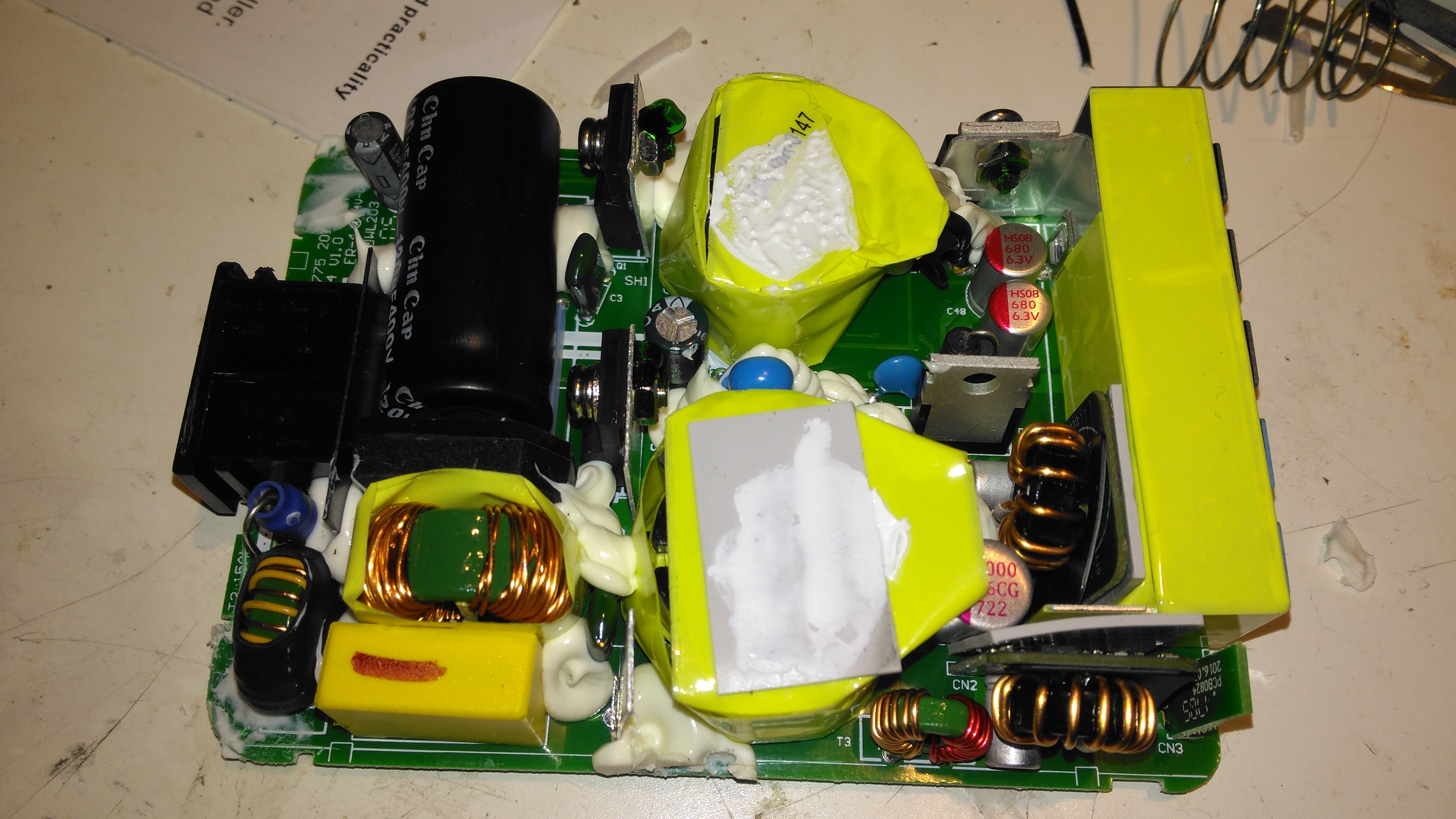
A few months ago I did a teardown on this Anker PowerPort Speed 5 USB charger, but I didn’t get round to detailing the conversion to 12v I had to do, so I’ll get to that now I’ve got a couple more to convert over.
Power Module
Here’s the internals of the Anker charger once I’ve removed the casing – which like many things these days, is glued together. (Joints can be cracked with a screwdriver handle without damaging the case). There’s lots of heatsinking in here to cool the primary side switching devices & the pot core transformers, so this is the first thing to get removed.
Heatsink Removed
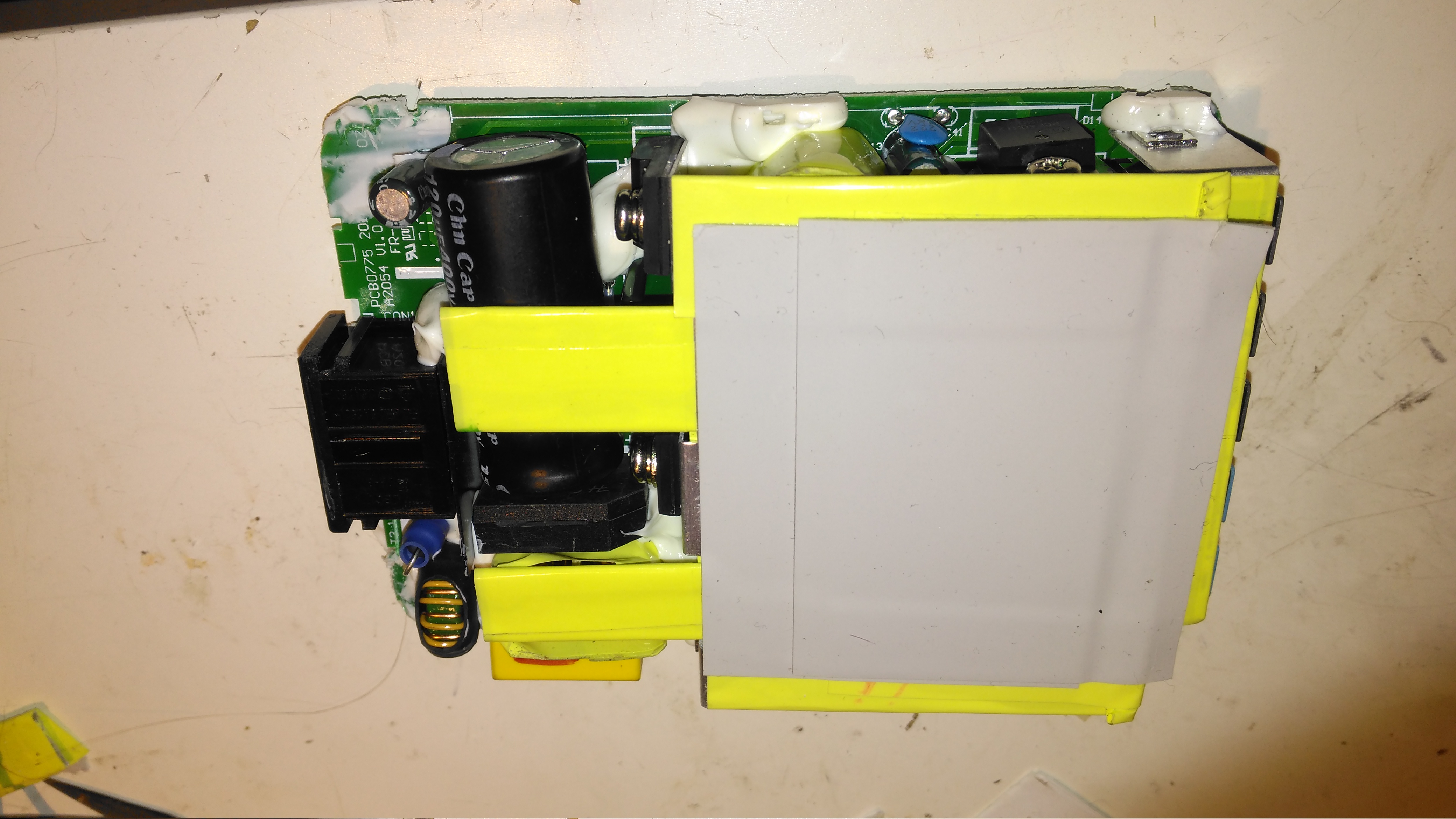
Once the heatsink has been removed, the pot core transformers are visible, wrapped in yellow tape. There’s some more heatsink pads & thermal grease here, to conduct heat better. The transformers, primary side switching components & input filter capacitor have to go.
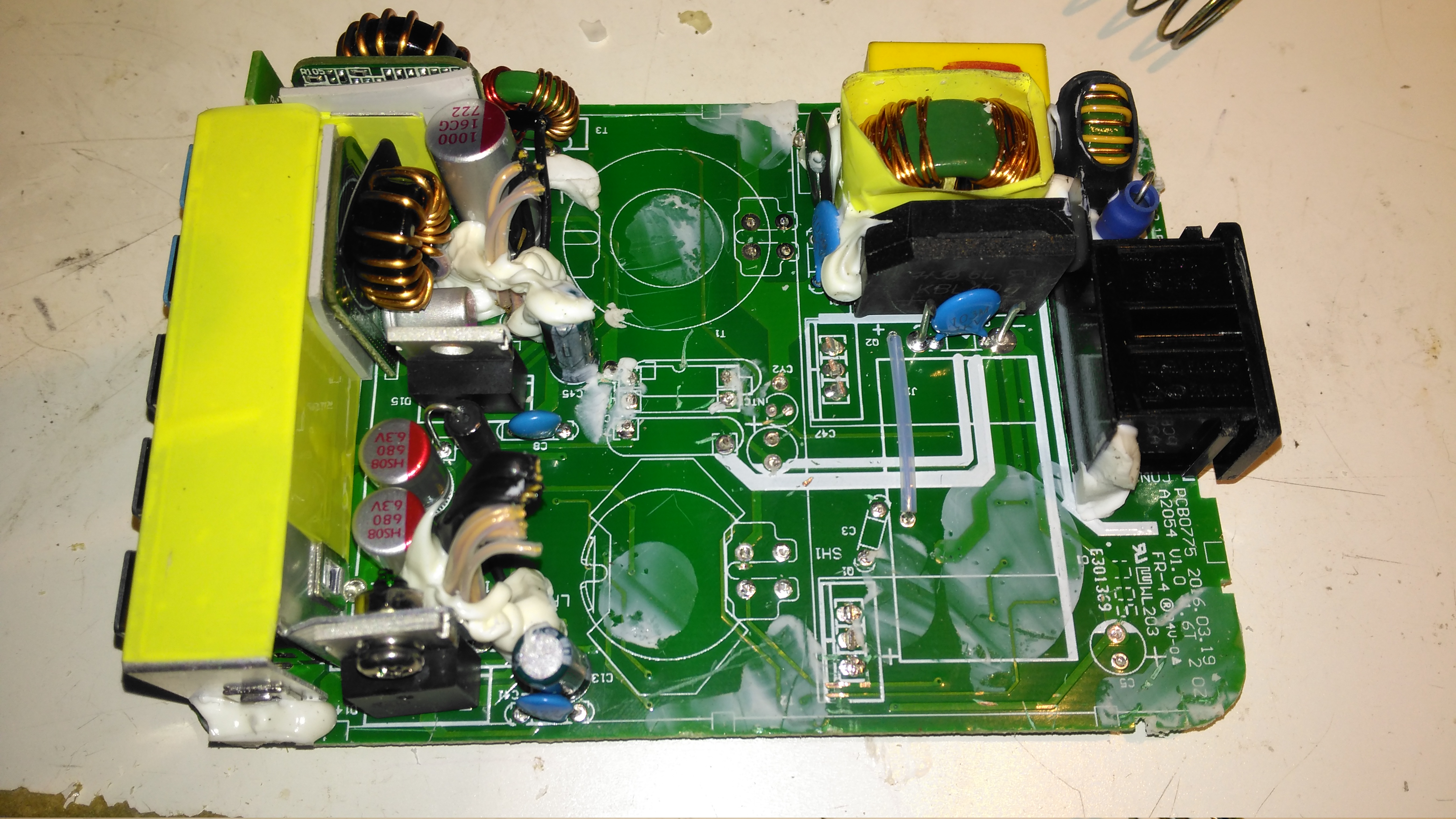
Primary Side Components Removed
Here’s the PCB once all the now redundant mains conversion components have been deleted. I’ve left the input filtering & bridge rectifier in place, as this solves the issue of the figure-8 cable on the input being reversible, polarity of the input doesn’t matter with the bridge. I’ve removed the main filter capacitor to make enough room for the DC-DC converters to be fitted.
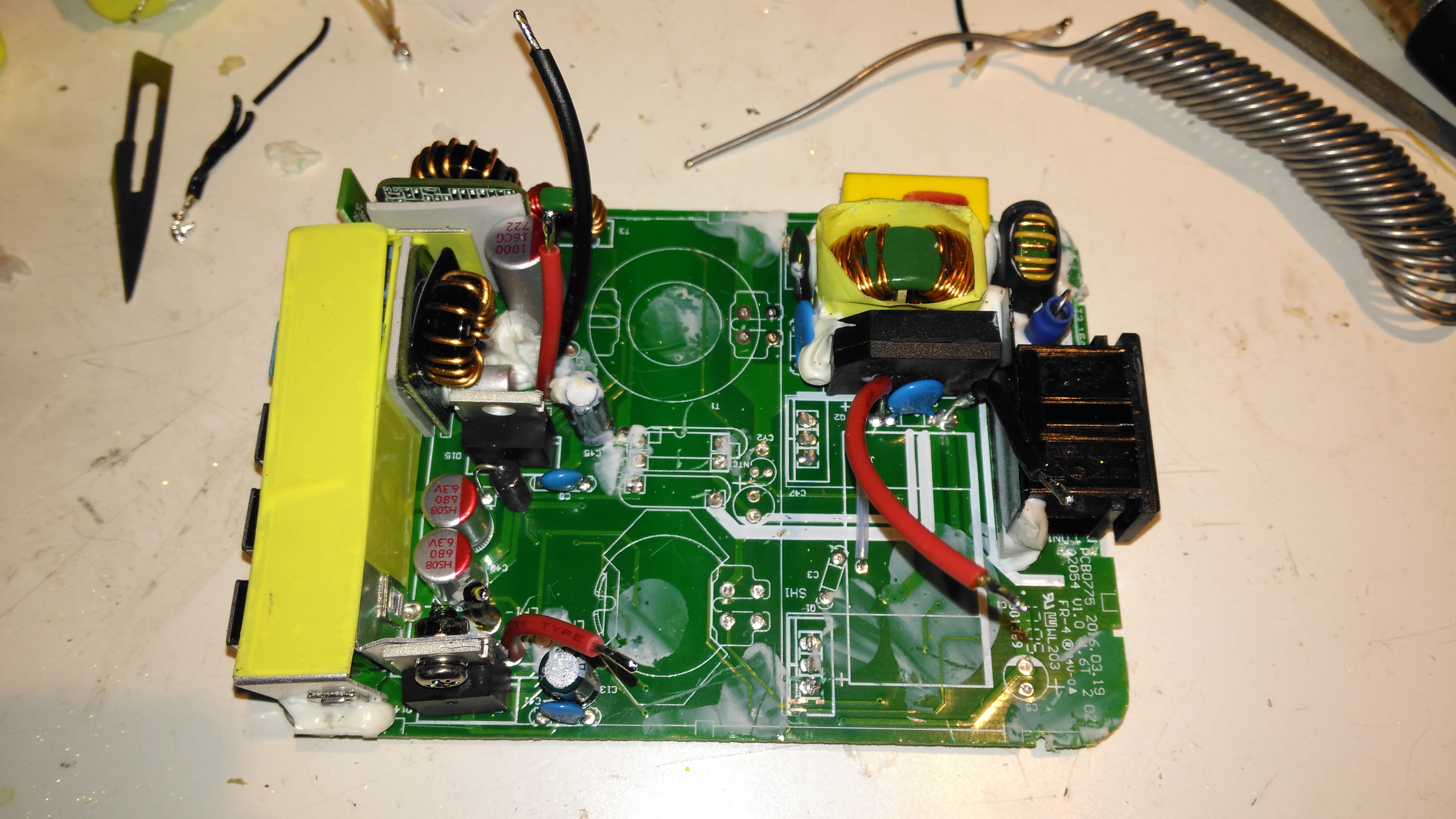
Tails Installed
Installing the tails to connect everything together is the next step, this charger requires two power supplies – the QC3 circuits need 14.4v to supply the multi-voltage modules, the remaining 3 standard ports require 5v. The DC input tails are soldered into place where the main filter capacitor was, while the outputs are fitted to the spot the transformer secondary windings ended up. I’ve left the factory Schottky rectifiers in place on the secondary side to make things a little more simple, the output voltages of both the DC-DC converters does need to be increased slightly to compensate for the diode drops though. I’ve also bypassed the mains input fuse, as at 12v the input current is going to be substantially higher than when used on mains voltage.
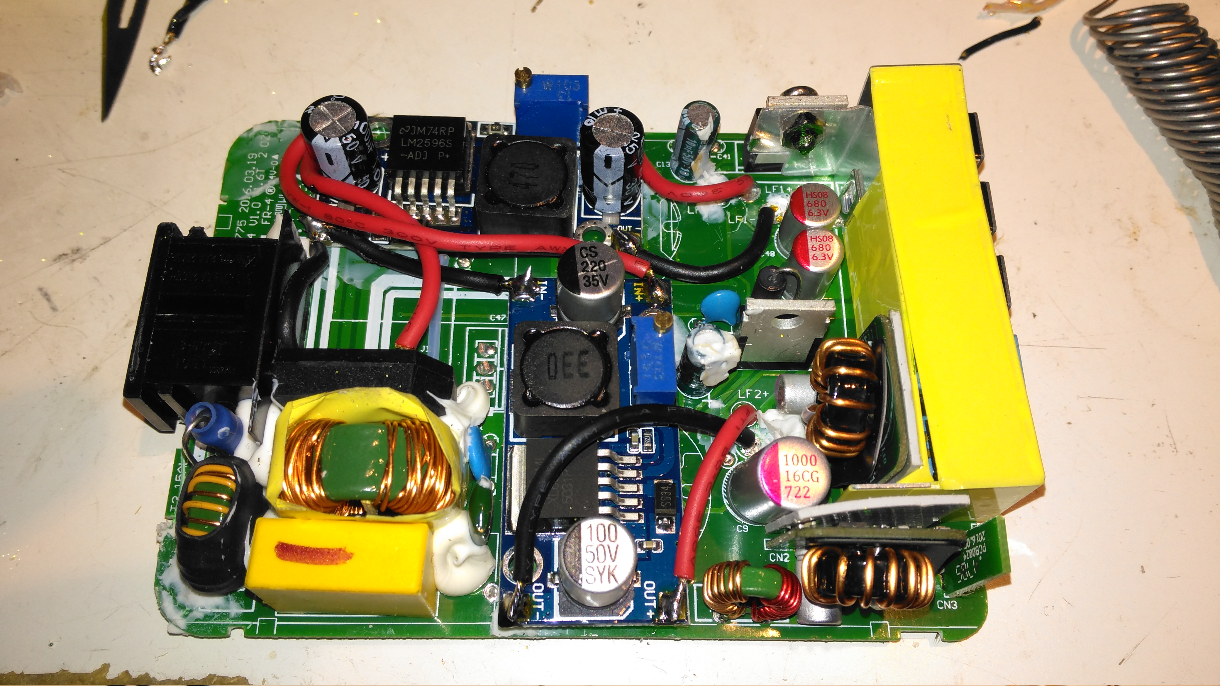
DC-DC Converters Installed
With a squeeze both the boost converter & the buck converter fit into place on the PCB.
It’s been a bit quiet around here for a couple of weeks, as it’s the run-up to Download Festival here in the UK, so I’ve been busy sorting everything out for that. Just in time a new order has come in!
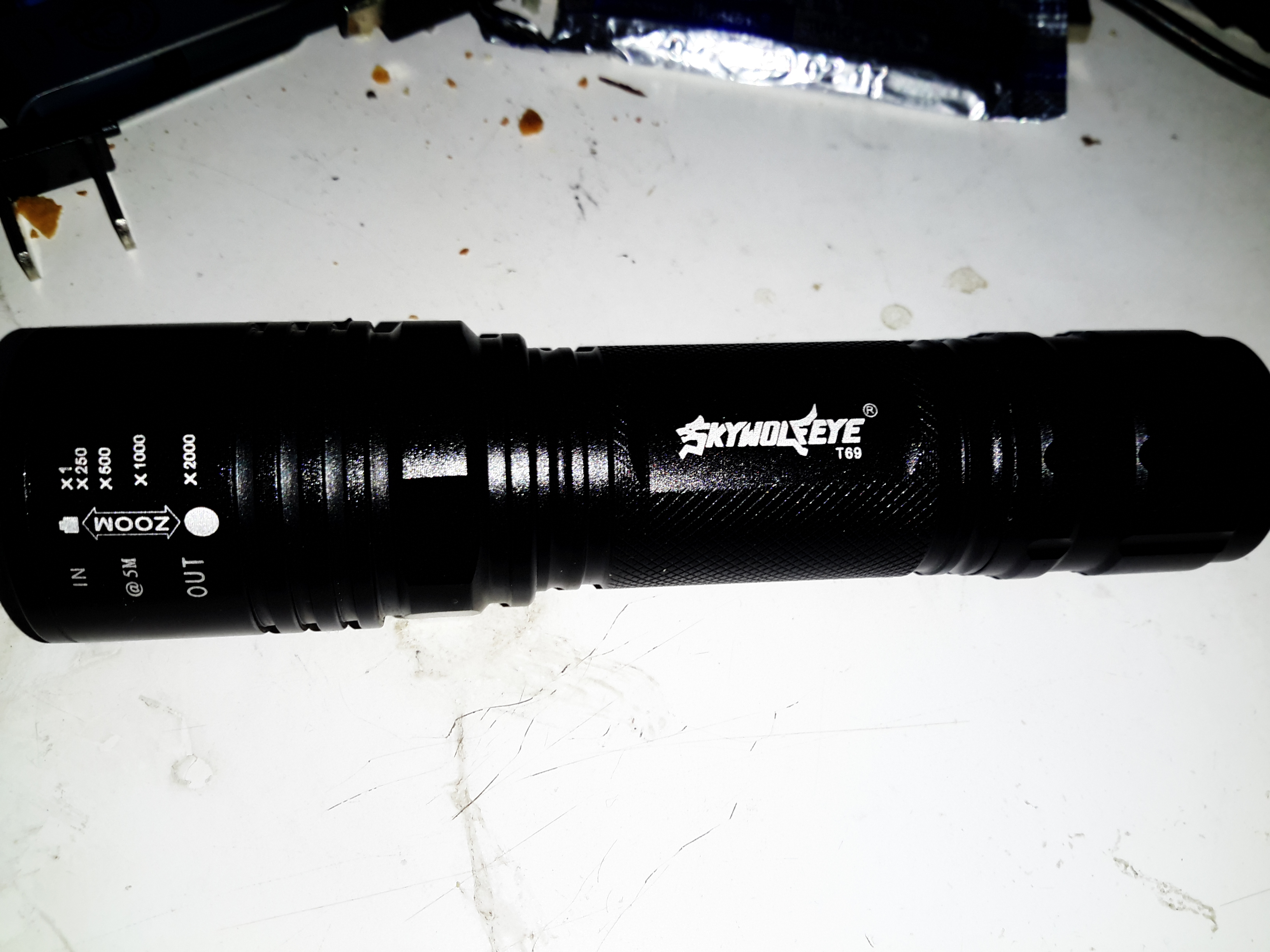
Due to a small accident with the old Maplin torch from a while back, (turns out they don’t float when dropped in the canal – ooops), a new one was sourced. Maplin is very expensive considering the imported crap they peddle these days, so I figured eBay would be the best bet for cheap imported crap 😉 This unit came with a few accessories, so I’ll start with the torch itself.
18650 Torch
This is an aluminium unit, and does feel quite well built for the price, but it does have a few disappointing things. The lens assembly at the front is movable so focus the beam – the range goes from wide flood to a very small spot.
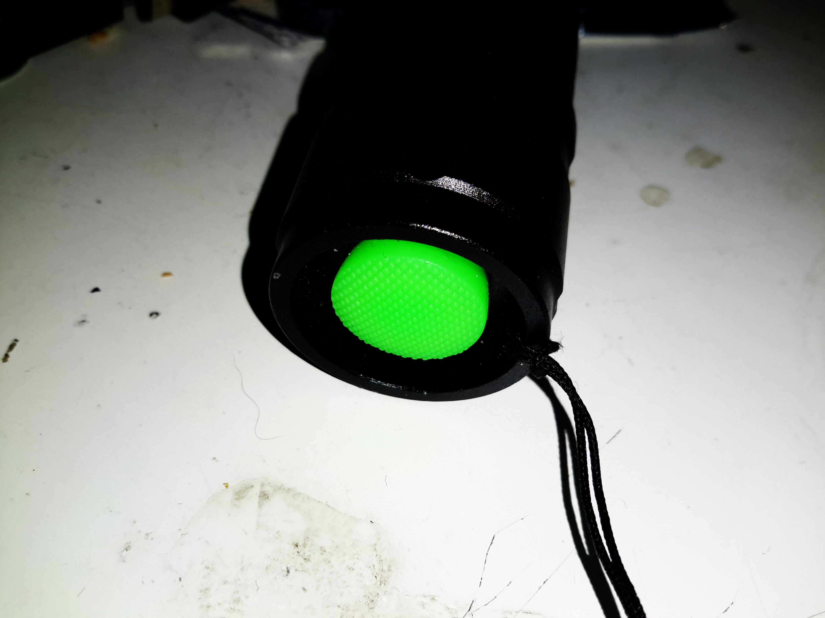
Power Switch
The power switch on this torch is at the back on the cap, covered by this obscenely brightly coloured cap.
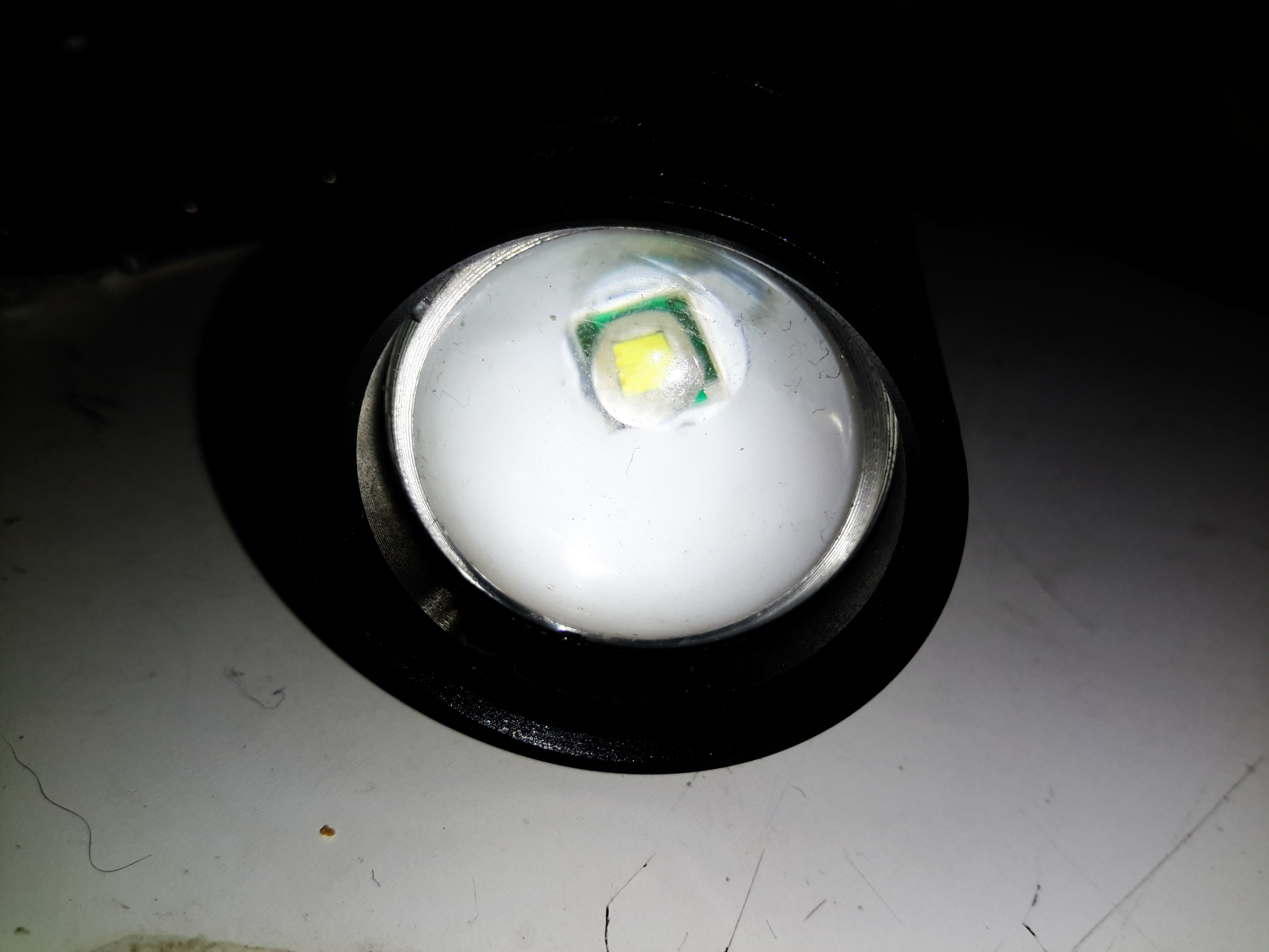
Lens Assembly
The lens is a simple plastic moulding, but it produces a nice wide beam.
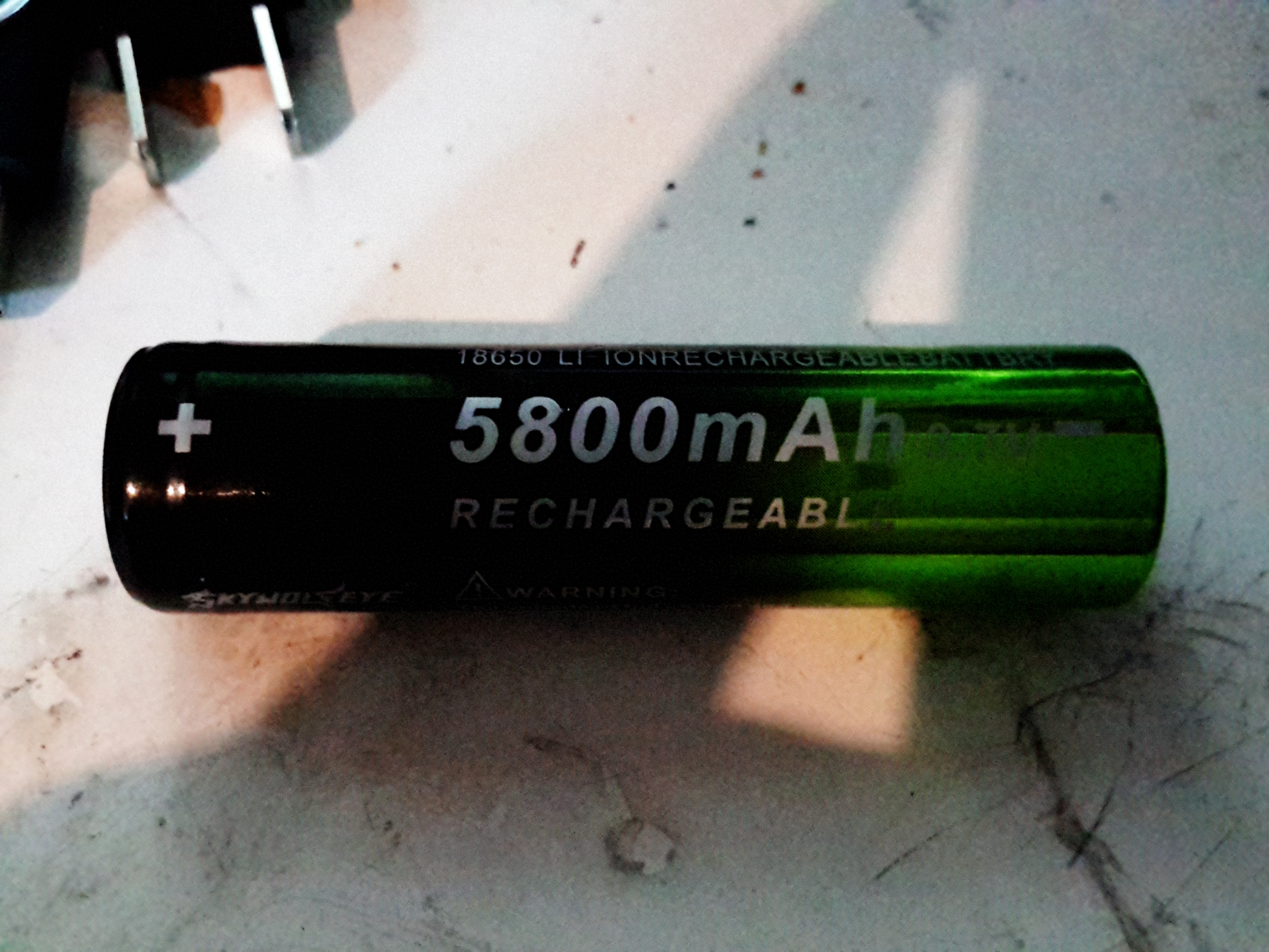
Enthusiastic Numbers
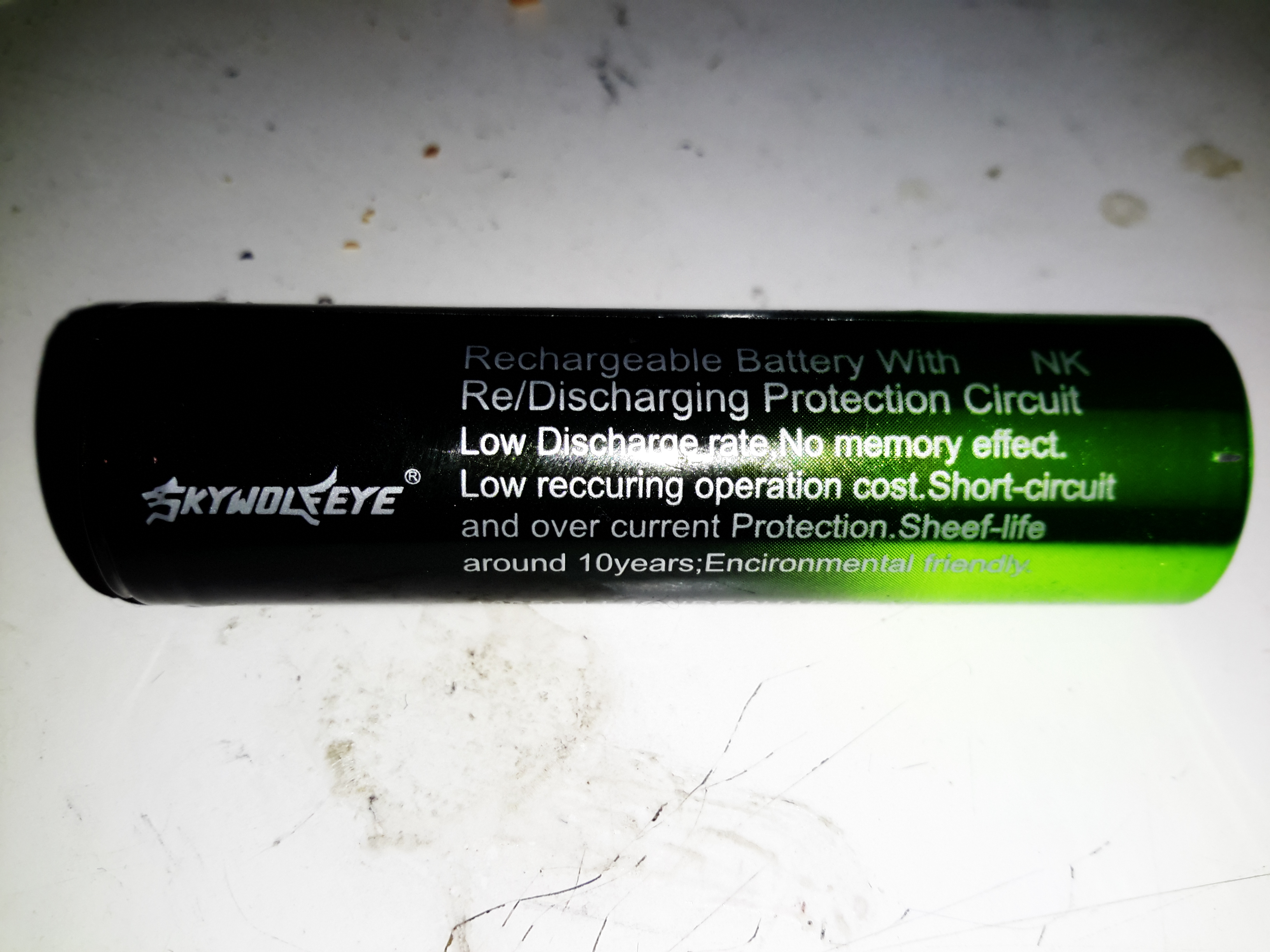
On to the battery supplied – this claims to be a 5.8Ah 18650 cell, which as far as I’m aware do not exist. I’m always dubious of lithium-ion cells from eBay, the Chinese seem to be well into a race to put the biggest numbers that will fit on the label. (I’ve even seen a USB powerbank claming to have 100Ah of capacity!). The largest capacity cells I have at present are LG HG2 18650s, and those are only rated at 3Ah a piece. They’re also relatively expensive.
Label
The manufacturer couldn’t even get the label spelling correct! Although they do apparently have a 10 year “sheef” life. Never seen that from an 18650 either. They tend to discharge on their own if left unused in about 12 months. I wouldn’t like to think of what the self-discharge rate of these dodgy things is, and I don’t intend to keep them to find out either!
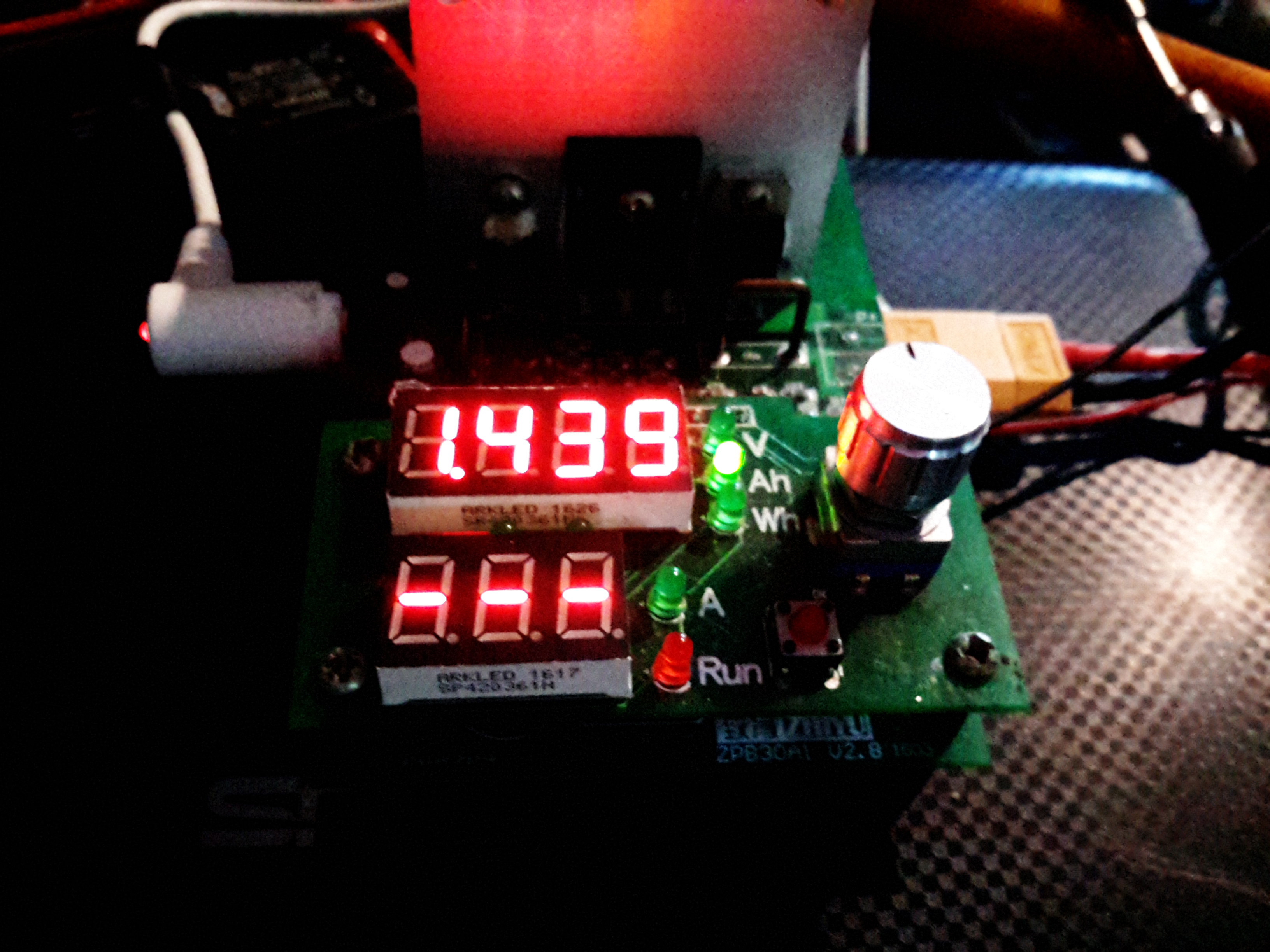
Battery Capacity
After a quick blast on the charger to top them up, on the discharge tester they go! This test was conducted at 1A, and this now shows the true capacity of 1.439Ah, which is honestly better than I was expecting. Already having high quality cells I wasn’t fussed about this aspect of the purchase, I knew these cells would end up in the bin.
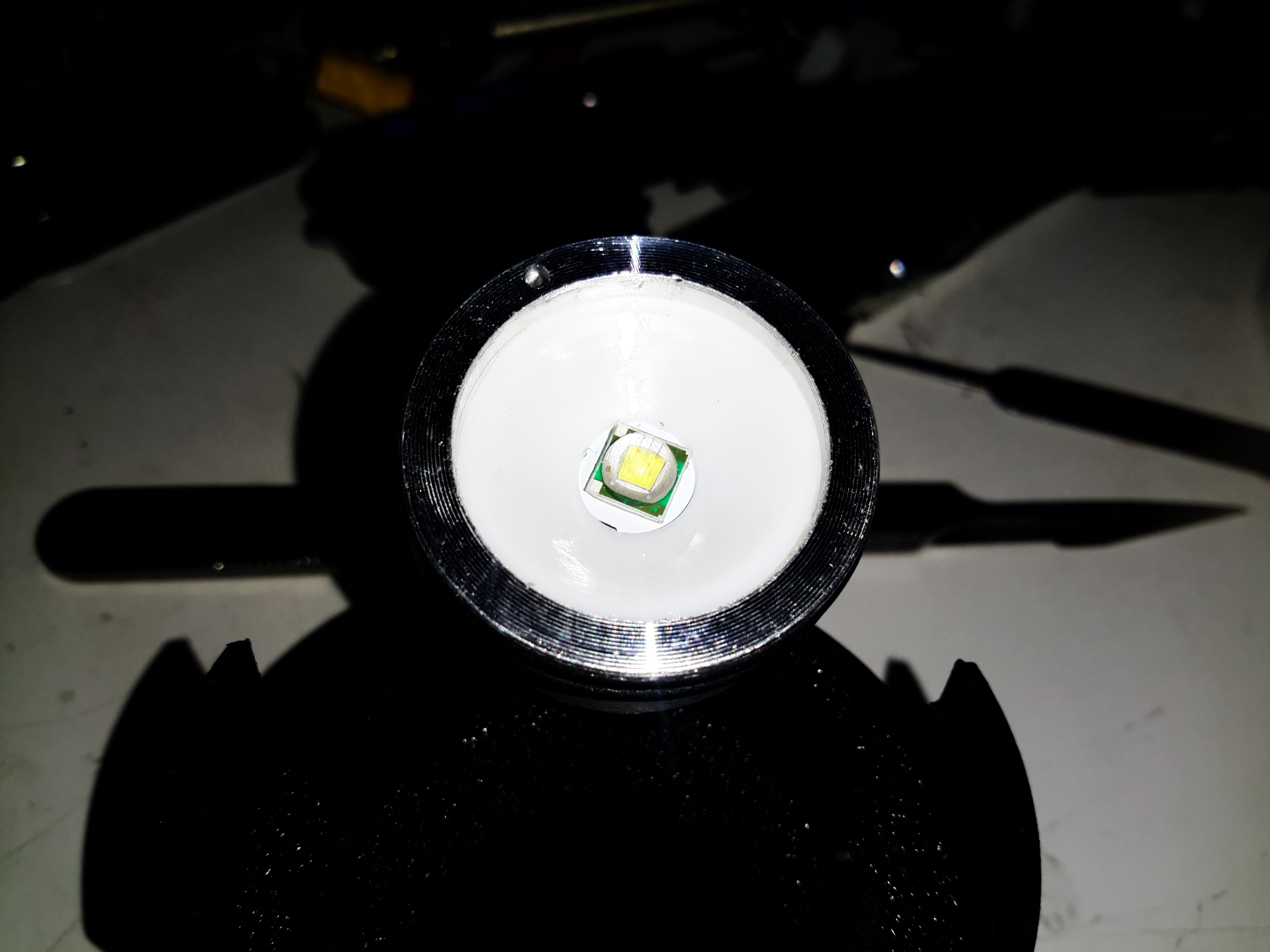
LED Module
Unscrewing the lens housing at the front gives access to the LED module – this is a Cree XM-L die in here, although it might not be a genuine Cree (or possibly a factory reject). The LED housing is aluminium, the LED uses this as a heatsink.
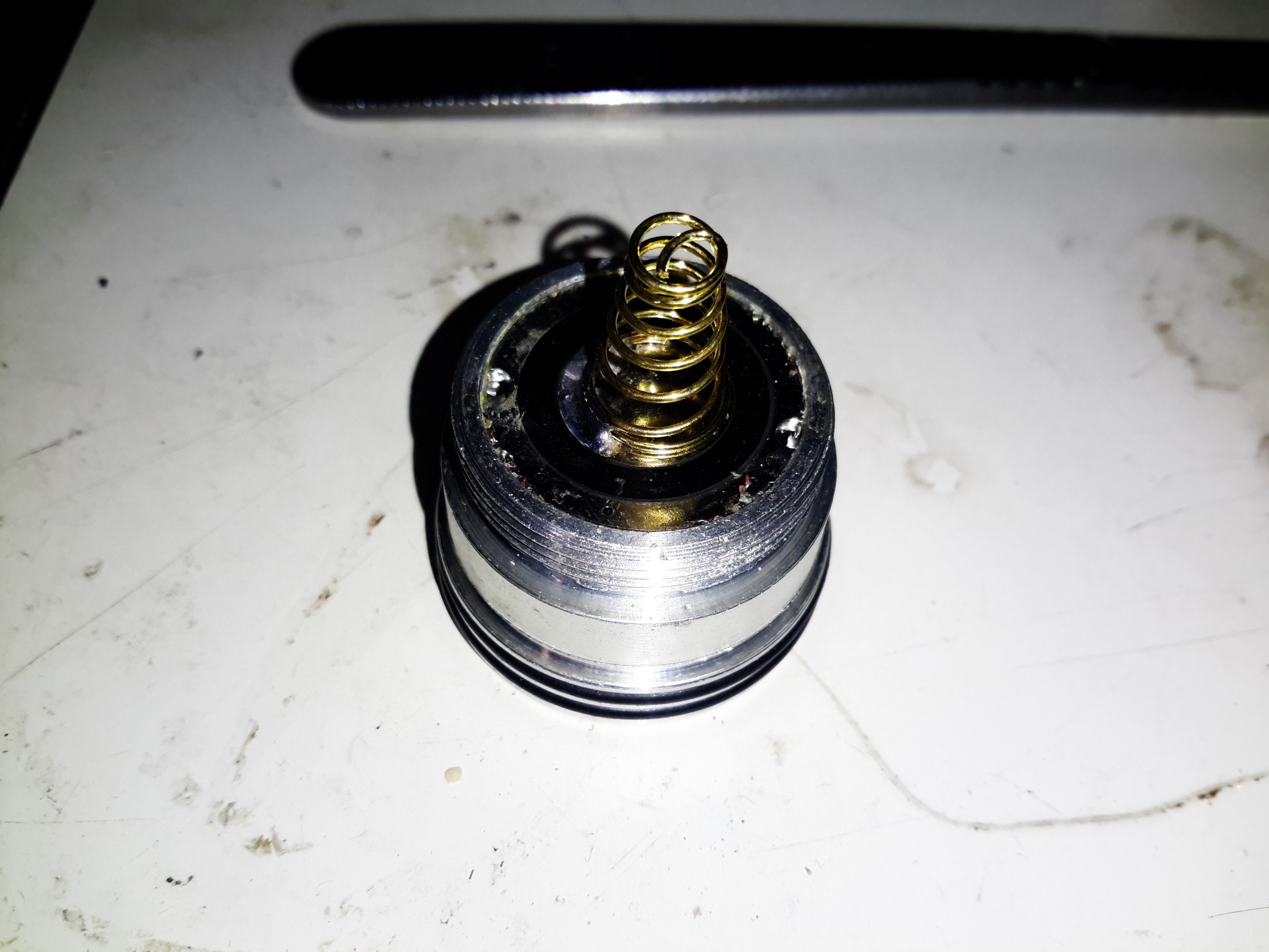
Positive Contact Spring
Nothing special about the back of the module after it’s been unscrewed from the barrel. There’s a couple of O-Rings to seal the sliding lens assembly, I lubricated these with some silicone grease to try & make the housing somewhat splashproof.
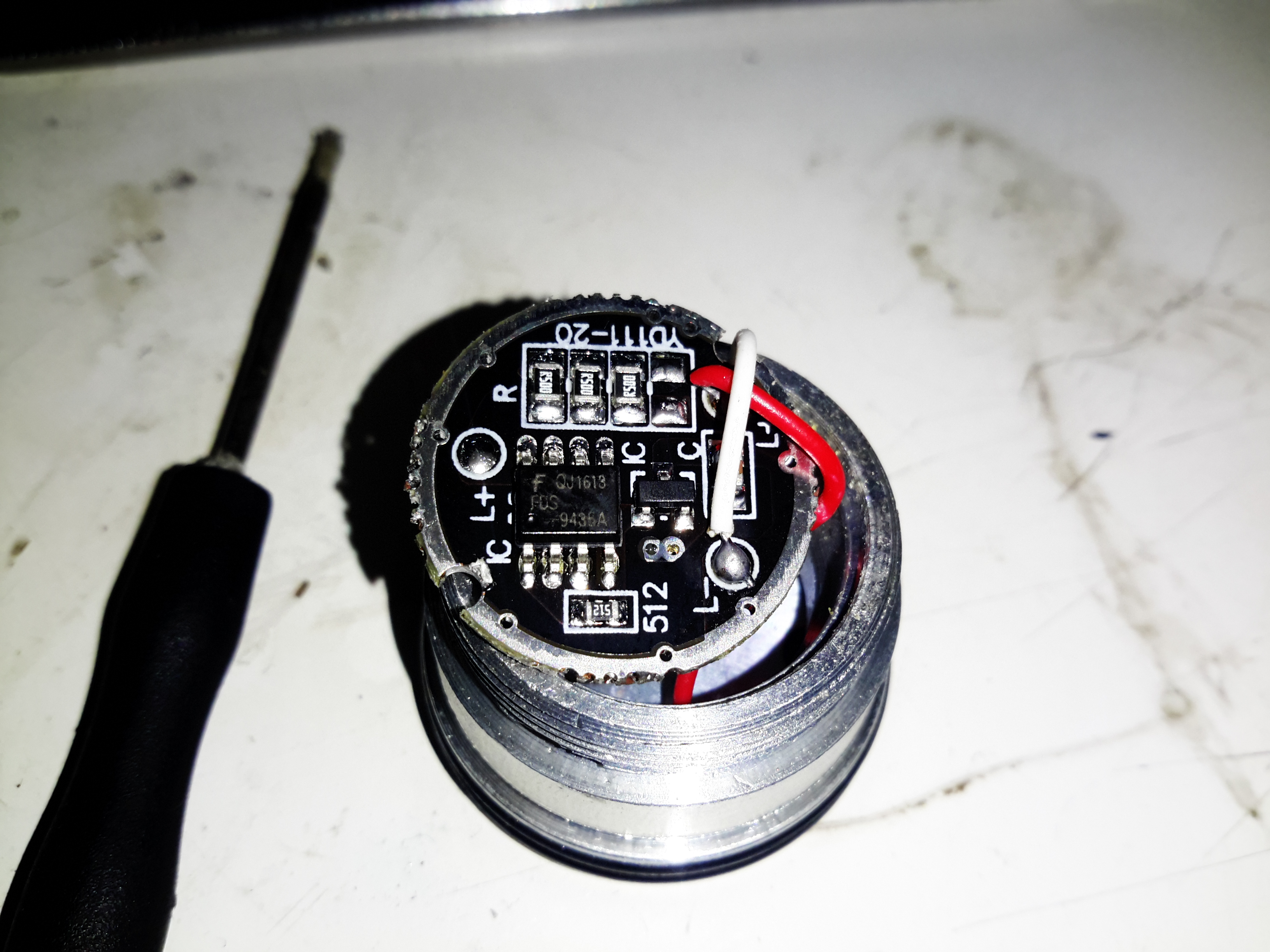
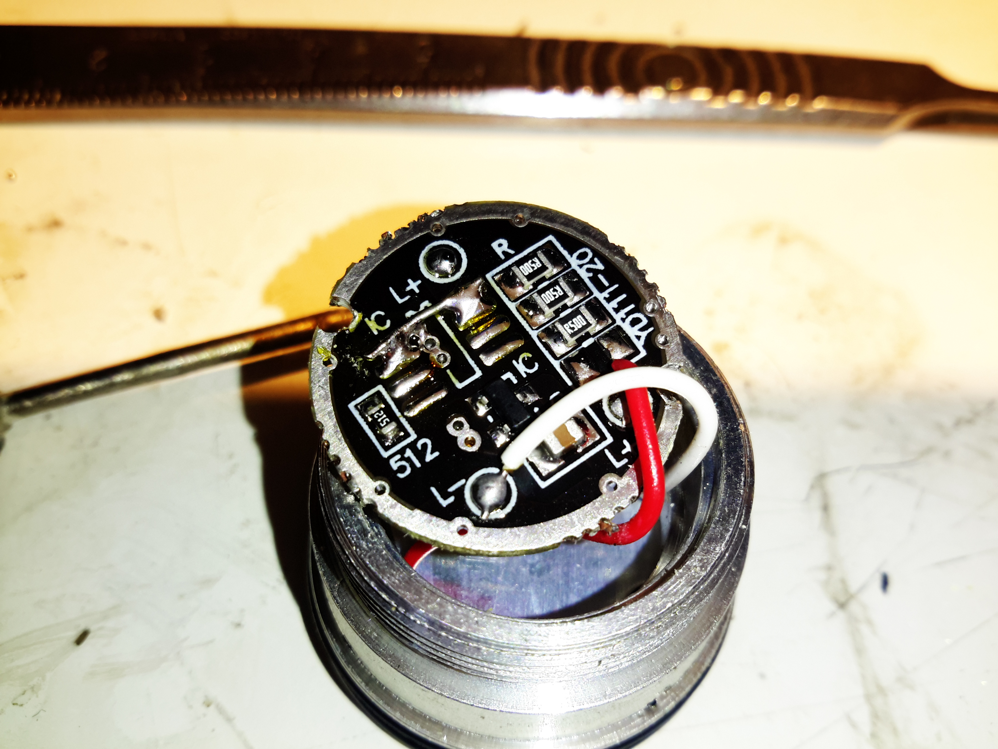
Control PCB
The control PCB is pulled out of the housing to reveal the circuitry. The LED is controlled by a SOT-23 mode IC & a SO-8 MOSFET. There’s nothing complex about the LED current limiting, just a bunch of SMD resistors in parallel to set the limit. This torch, like 99% of Chinese import torches from eBay, has a multi-mode IC with SOS & strobe. I don’t need this crap, and it’s easily bypassed.
Modifications
Here I’ve desoldered the MOSFET from the board & jumped across it’s drain & source connections, converting the torch to simple ON/OFF control.
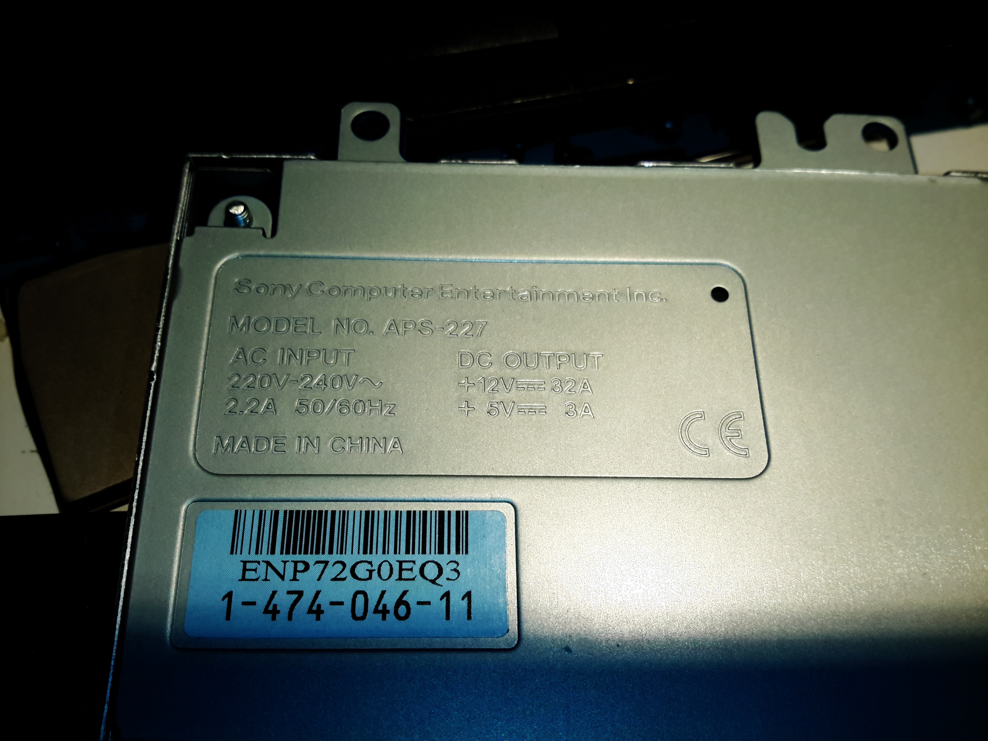
Since I’ve discovered some nice high power PSUs in the form of Playstation 3 PSUs, it’s time to get a new Bench PSU Build underway!
Specifications
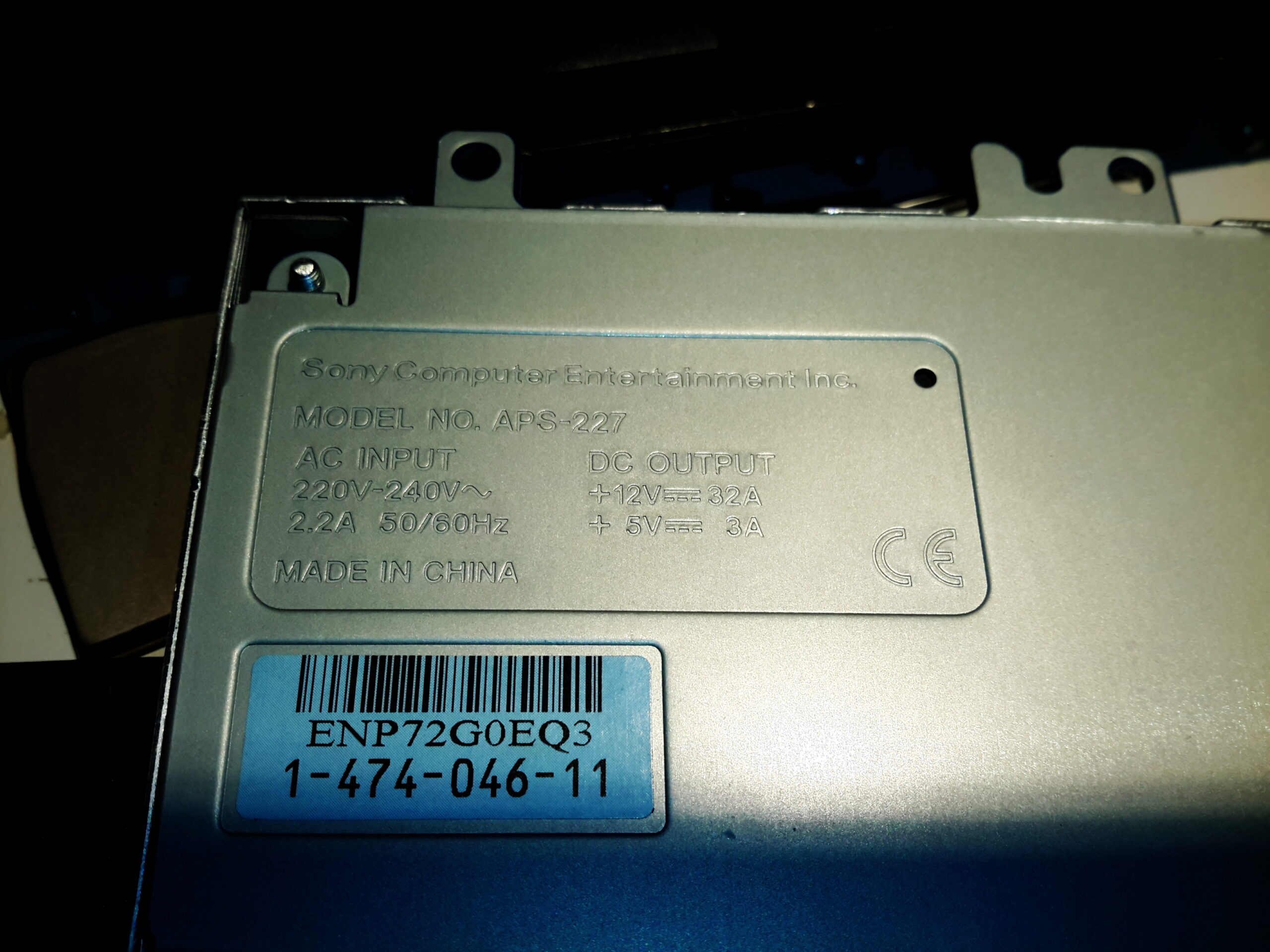
I’ve gone for the APS-227 version as it’s got the 32A rail. This makes things slightly beefier overall, as the loading will never be anywhere close to 100% for long, more headroom on the specs is the result.
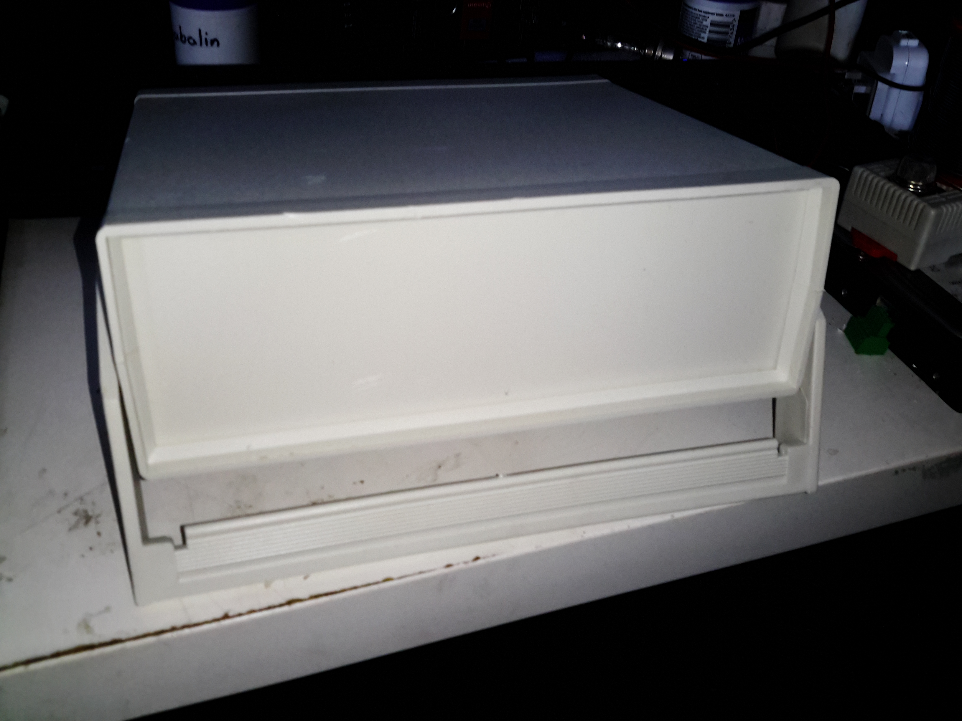
Desktop Instrument Case
The case I’ve chosen for this is an ABS desktop instrument case from eBay, the TE554 200x175x70mm. The ABS is easy to cut the holes for all the through-panel gear, along with being sturdy enough. Aluminium front & back panels would be a nice addition for a better look.
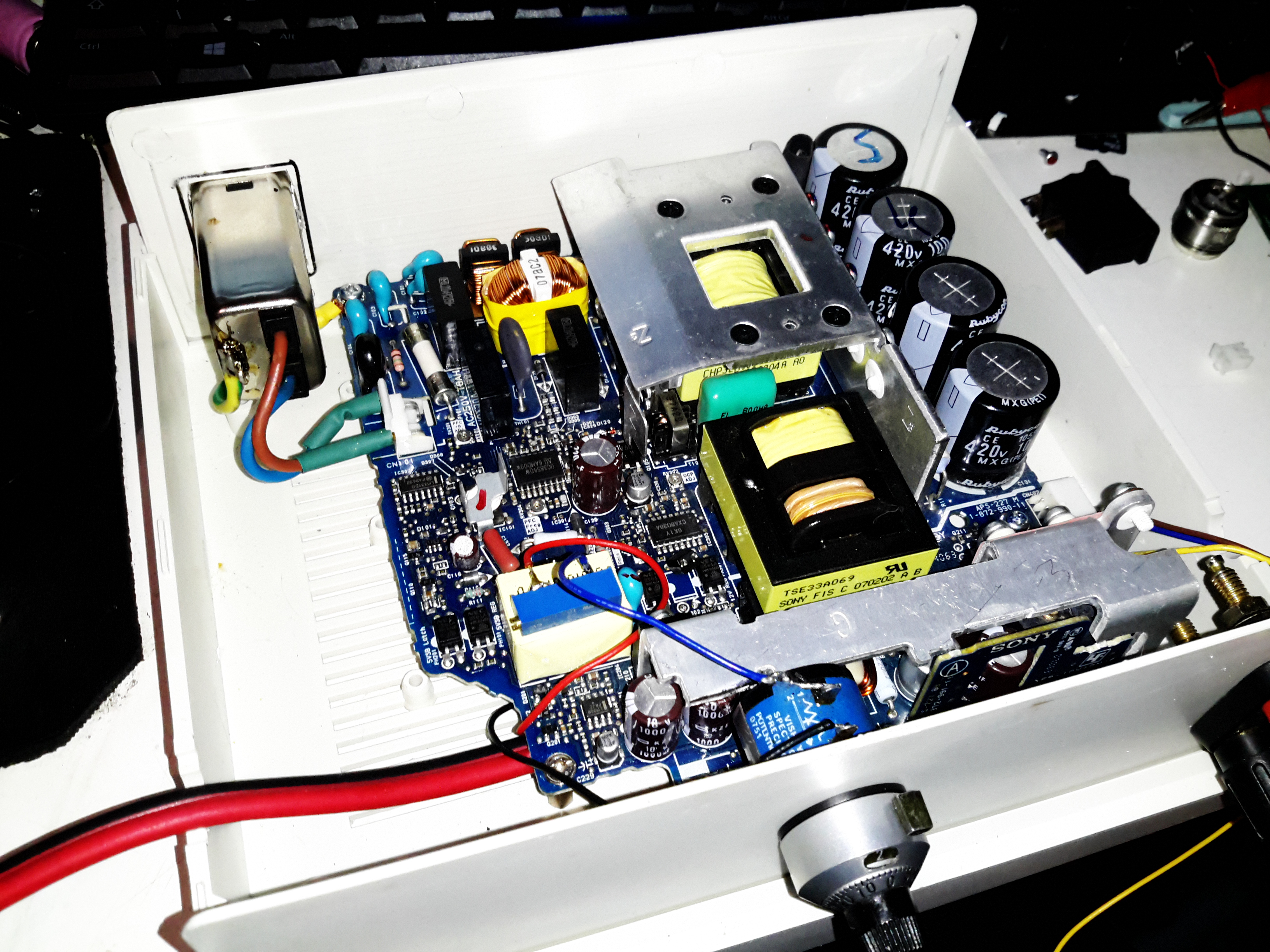
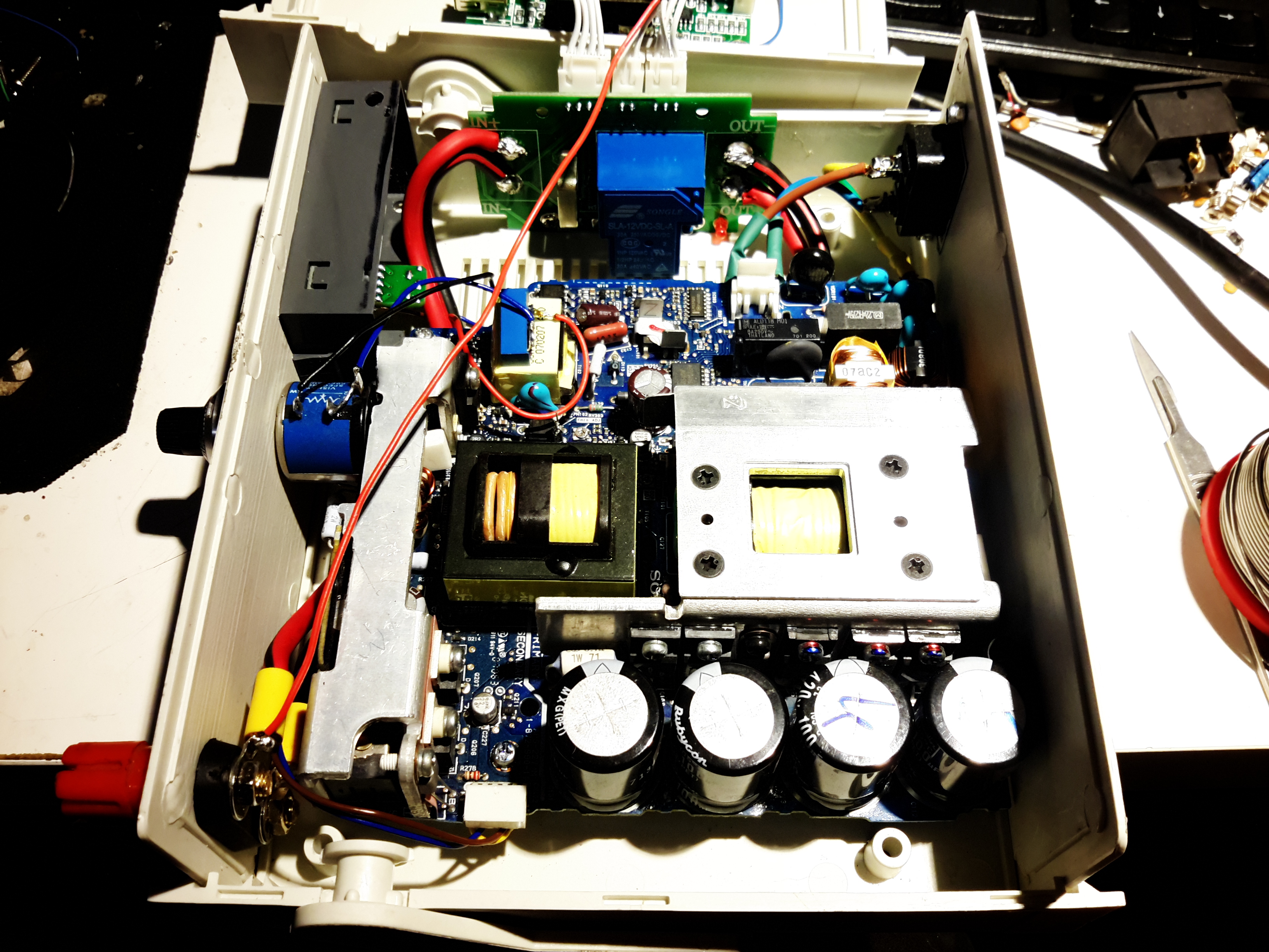
PSU Mounted
The PSU board is removed from it’s factory casing & installed on the bottom shell half, unfortunately the moulded-in posts didn’t match the screw hole locations so I had to mount some brass standoffs separately. The AC input is also fitted here, I’ve used a common-mode filter to test things (this won’t be staying, as it fouls one of the case screw holes). The 40A rated DC output cable is soldered directly to the PCB traces, as there’s no room under the board to fit the factory DC power connector. (This is the biggest case I could find on eBay, and things are still a little tight). Some minor modifications were required to get the PCB to fit correctly.
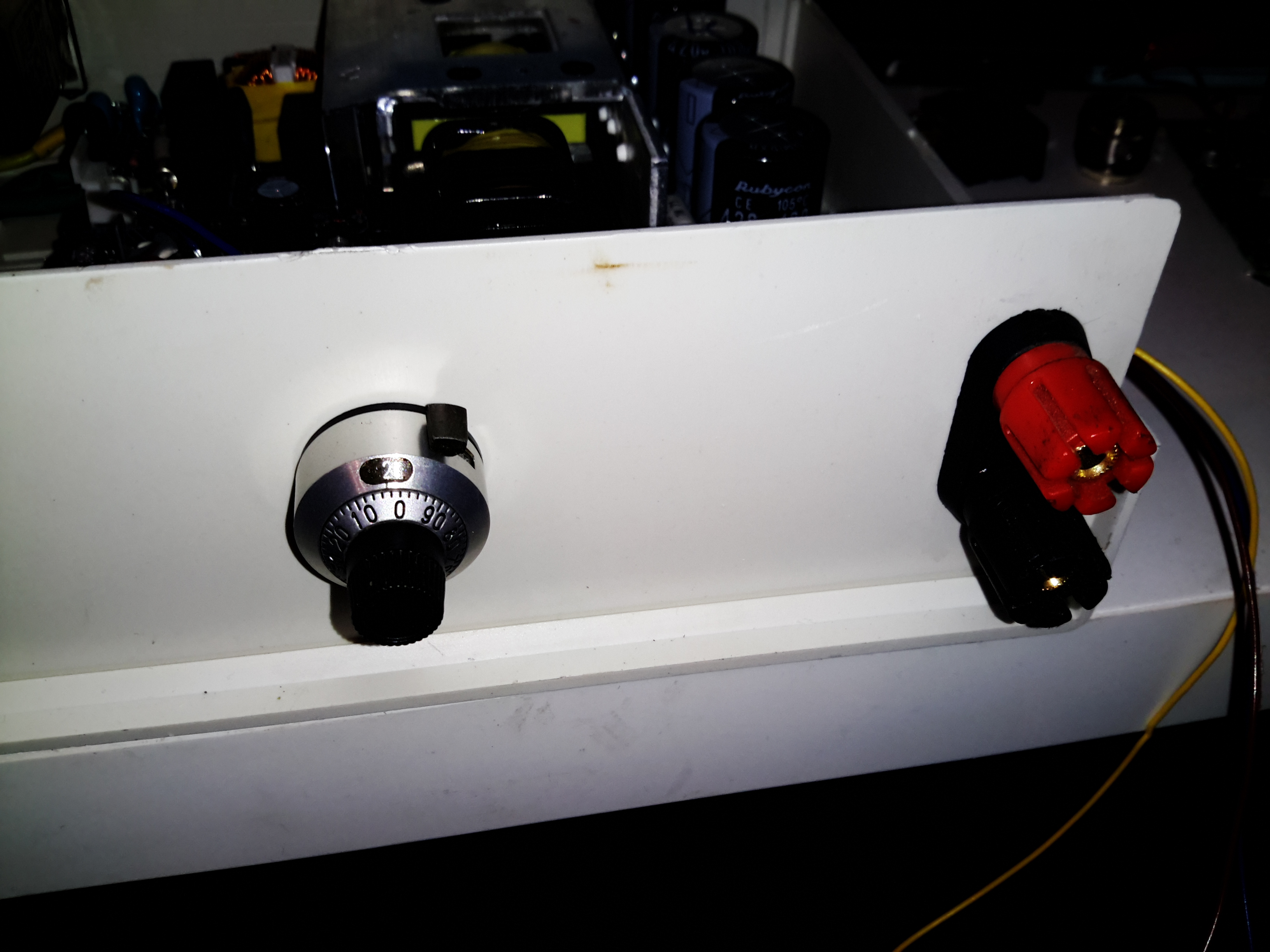
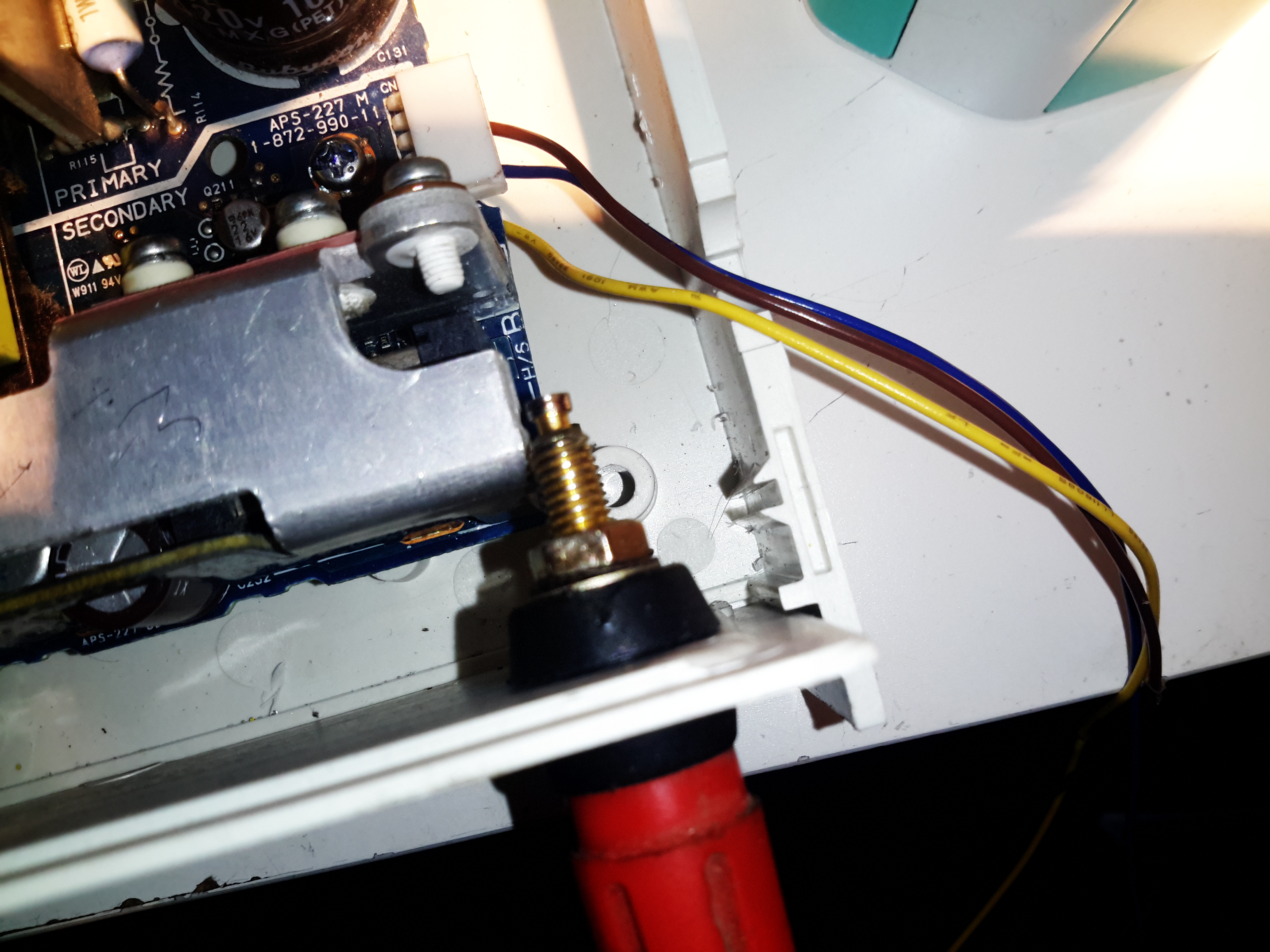
Output Terminals & Adjuster
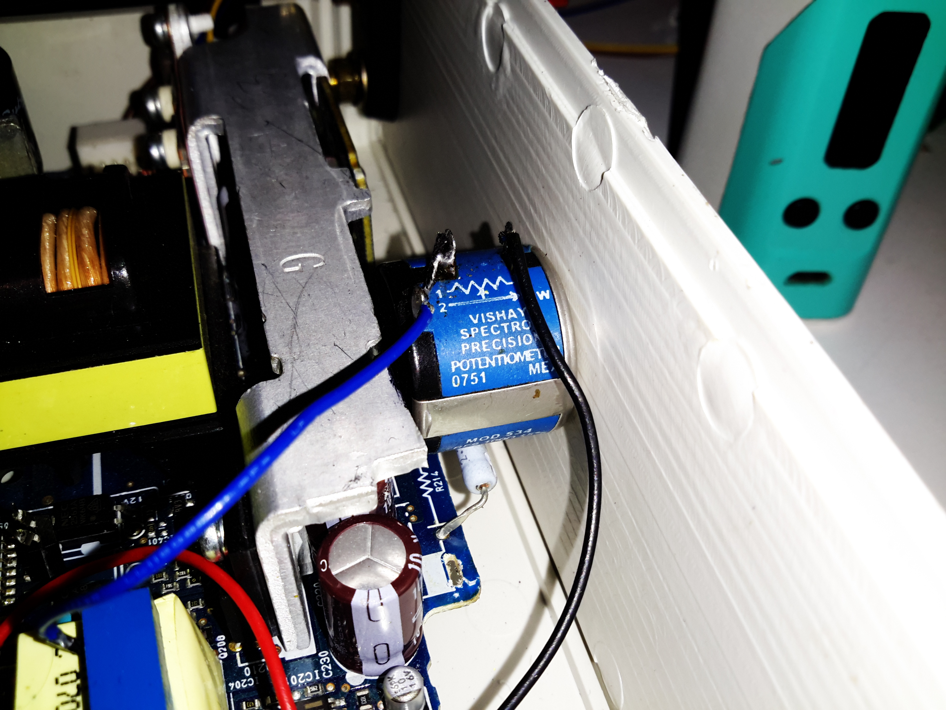
I decided to add some limited voltage adjustment capability to the front panel, I had a 100Ω Vishay Spectrol Precision 10-turn potentiometer in my parts bin, from a project long since gone that just about fits between the panel & the output rectifier heatsink. The trimpot I added when I first posted about these PSUs is now used to set the upper voltage limit of 15 volts. (The output electrolytics are 16v rated, and are in an awkward place to get at to change for higher voltage parts). The binding posts are rated to 30A, and were also left over from a previous project.
Vishay Spectrol 10-Turn
Addon Regulator Components
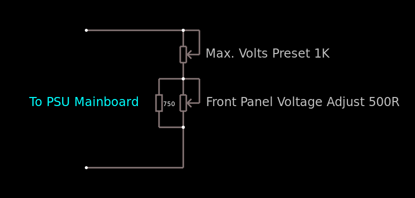
This front panel potentiometer is electrically in series with the trimpot glued to the top of the auxiliary transformer, see above for a simple schematic of the added components. In this PSU, reducing the total resistance in the regulator circuit increases the voltage, so make sure the potentiometer is wired correctly for this!
After some experimentation, a 500Ω 10-turn potentiometer would be a better match, with a 750Ω resistor in parallel to give a total resistance range on the front panel pot of 300Ω. This will give a lower minimum voltage limit of about 12.00v to make lead-acid battery charging easier.
I’ve had to make a minor modification to the output rectifier heatsink to get this pot to fit in the available space, but nothing big enough to stop the heatsink working correctly.
Terminal Posts
Here I’ve got the binding posts mounted, however the studs are a little too long. Once the wiring is installed these will be trimmed back to clear both the case screw path & the heatsink. (The heatsink isn’t a part of the power path anyway, so it’s isolated).
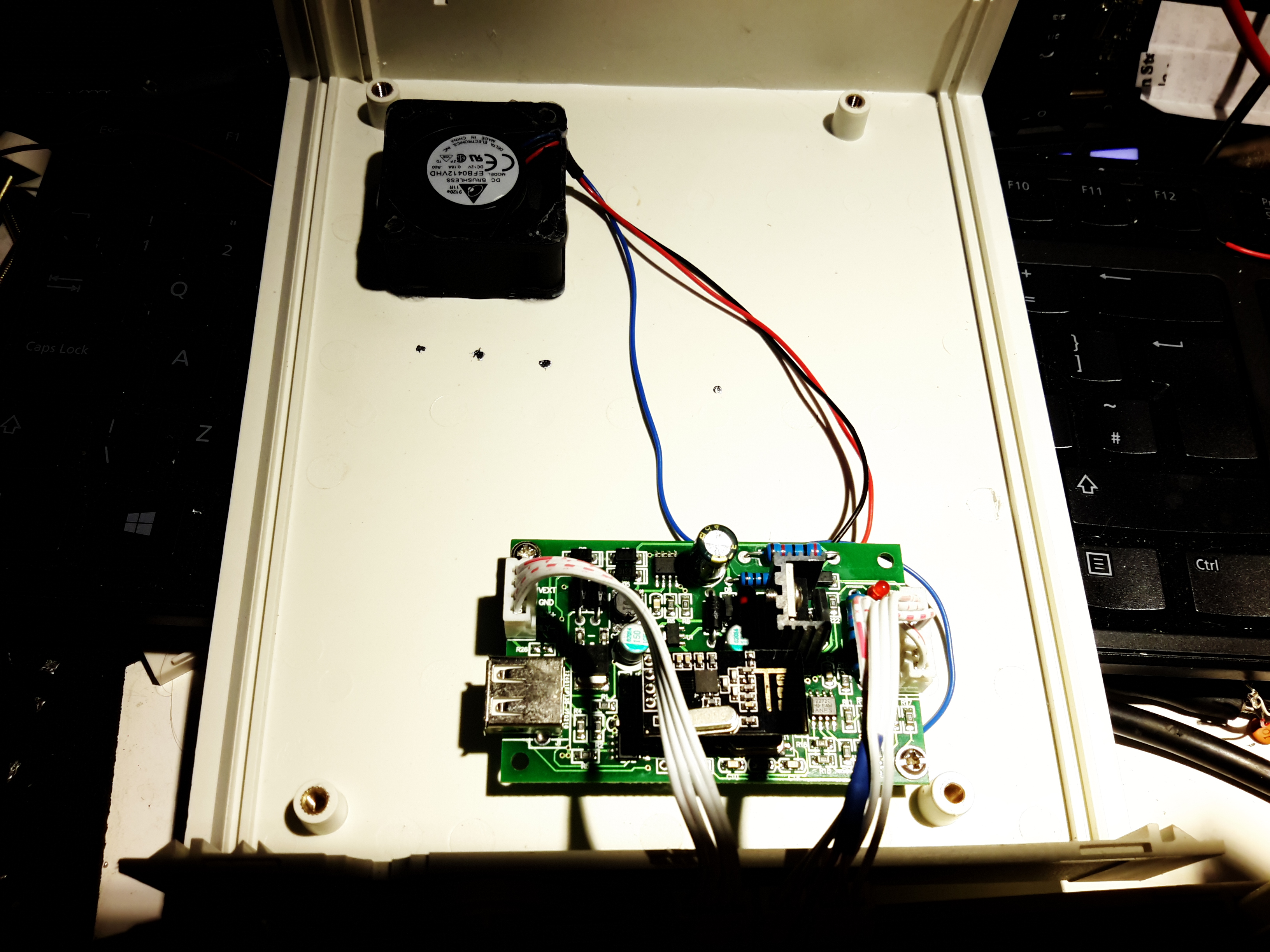
Power Meter Control Board & Fan
To keep the output rectifier MOSFETs cool, there’s a fan mounted in the upper shell just above their location, this case has vents in the bottom already moulded in for the air to exit. The fan is operated with the DC output contactor, only running when the main DC is switched on. This keeps the noise to a minimum when the supply doesn’t require cooling. The panel meter control board is also mounted up here, in the only empty space available. The panel meter module itself is a VAC-1030A from MingHe.
Meter Power Board
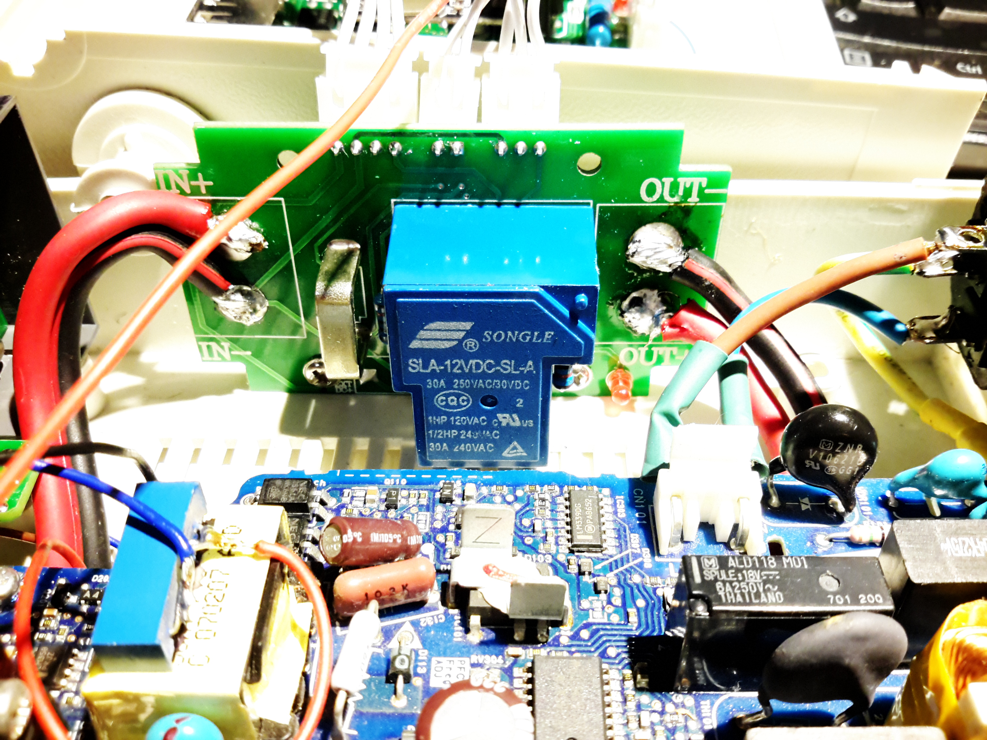
The measurement shunt & main power contactor for the DC output is on another board, here mounted on the left side of the case. The measurement shunt is a low-cost one in this module, I doubt it’s made of the usual materials of Manganin or Constantan, this is confirmed by my meansurements as when the shunt heats up from high-power use, the readings drift by about 100mA. The original terminal blocks this module arrived with have been removed & the DC cables soldered directly to the PCB, to keep the number of high-current junctions to a minimum. This should ensure the lowest possible losses from resistive heating.
Meter Panel Module
The panel meter module iself is powered from the 5v standby rail of the Sony PSU, instead of the 12v rail. This allows me to keep the meter on while the main 12v output is switched off.
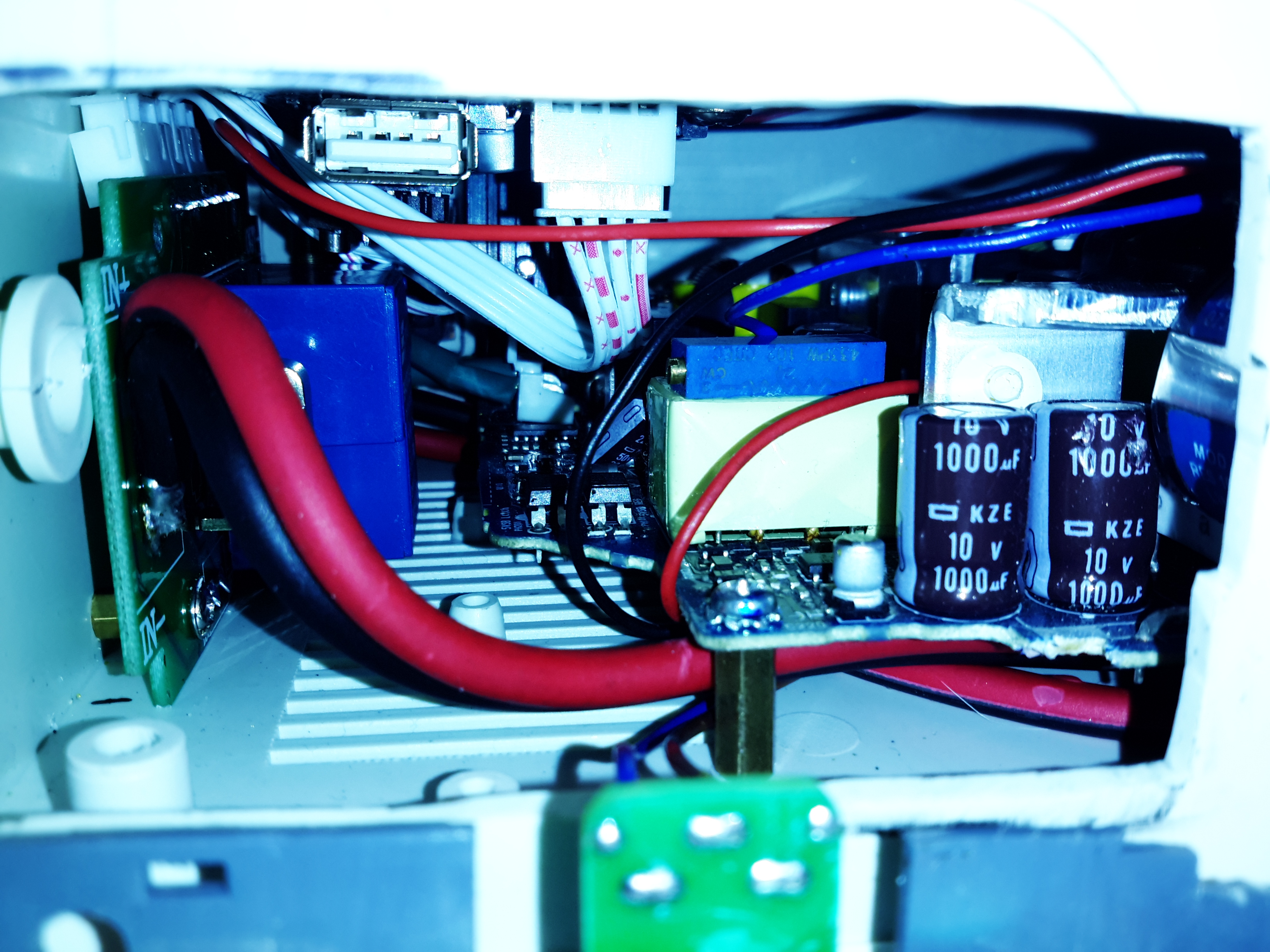
PSU Internals
here’s the supply with everything fitted to the lower shell – it’s a tight fit! A standard IEC connector has been fitted into the back panel for the mains input, giving much more clearance for the AC side of things.
Inside View
With the top shell in place, a look through the panel cutout for the meter LCD shows the rather tight fit of all the meter components. There’s about 25mm of clearance above the top of the PSU board, giving plenty of room for the 40mm cooling fan to circulate air around.
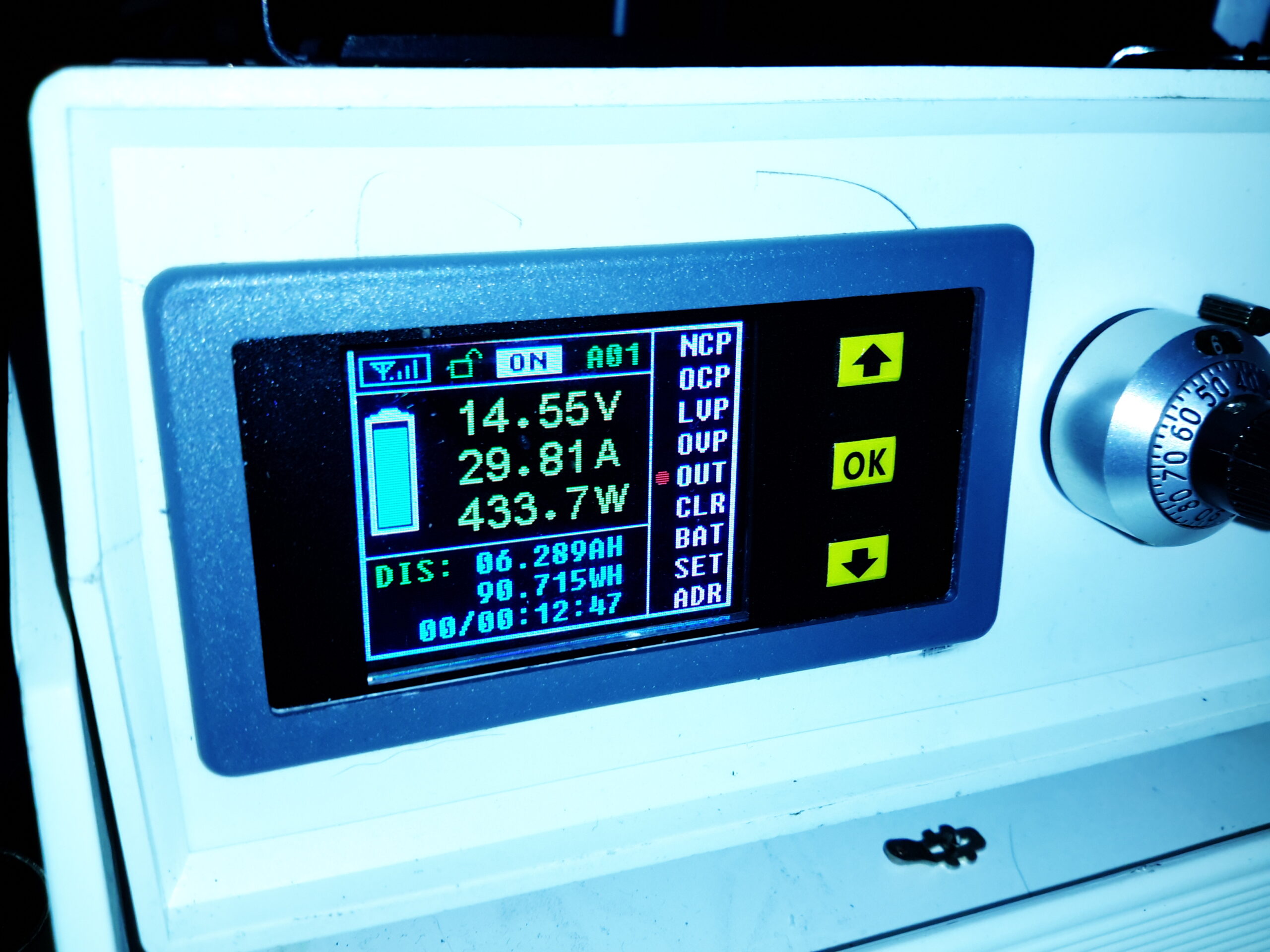
Load Test
Here’s the finished supply under a full load test – it’s charging a 200Ah deep cycle battery. The meter offers many protection modes, so I’ve set the current limit at 30A – preventing Sony’s built in over current protection on the PSU tripping with this function is a bonus, as the supply takes a good 90 seconds to recover afterwards. I’ll go into the many modes & features of this meter in another post.
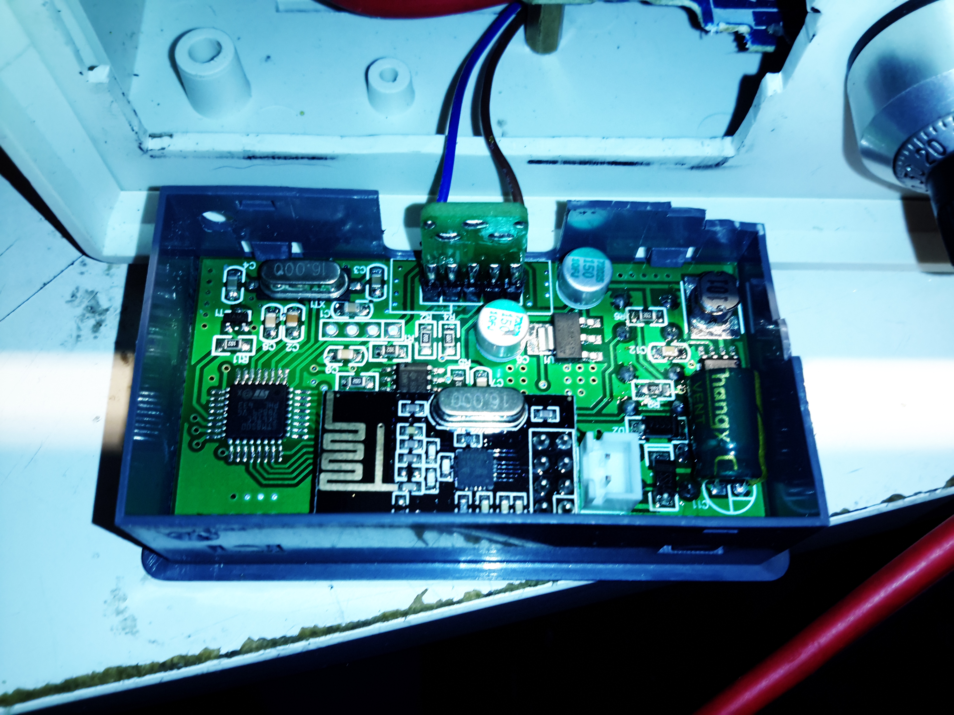
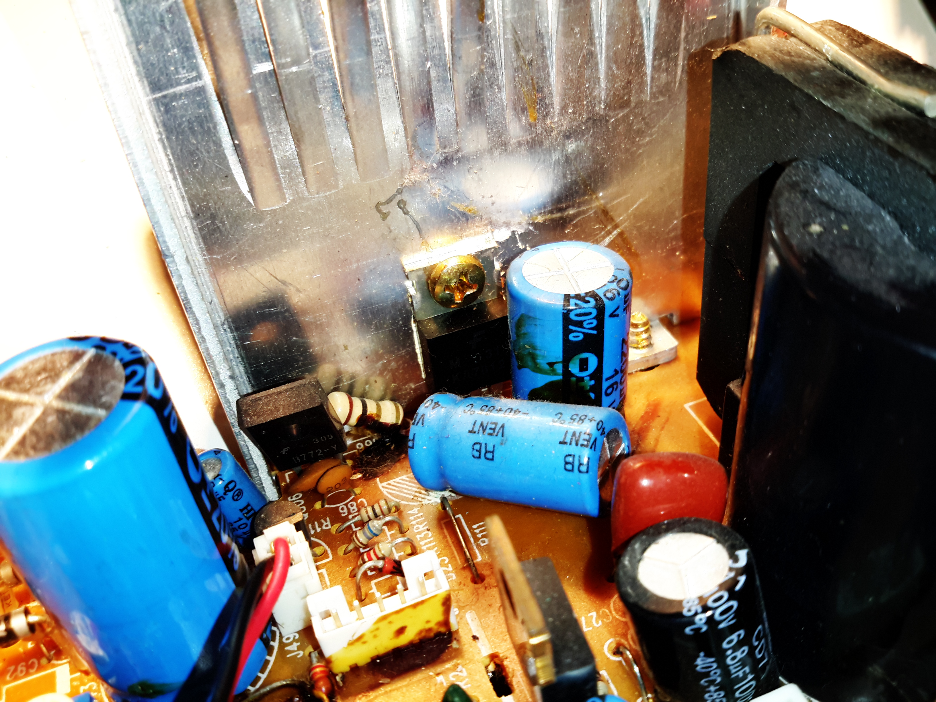
Here’s the CRT circuitry from a tossed STVG-502 Karaoke Machine, which got a good soaking in Manchester’s brilliantly wet weather before I managed to get hold of it:
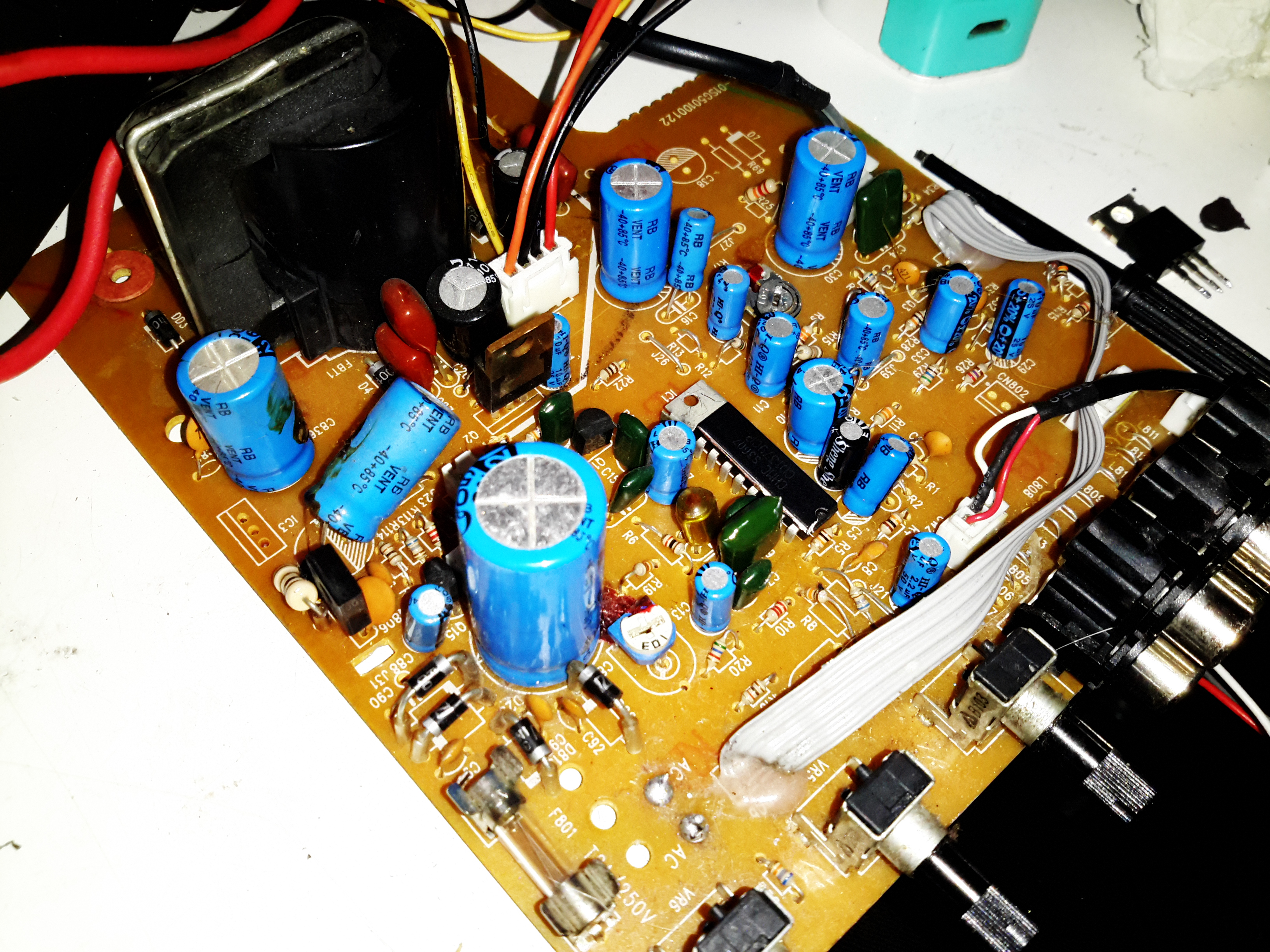
Main PCB
I didn’t do a full teardown of this unit, since it was soaking wet & smelled rather badly of sour milk, so instead I quickly gutted it for the useful parts. These machines are a combination of a CD+G player, CRT composite monitor for displaying the CD+G lyrics & a small audio amplifier & 3W speaker. Power is provided from the mains via a transformer, with both 12 & 24v windings. One half of the board has the audio amplifier sections, the other the CRT drive, running from the 12v & 24v supplies respectively. I chopped off the audio section, as that wasn’t needed.
Linear Regulator
On this huge heatsink is what I originally thought was the horizontal drive transistor is actually a 12v linear regulator – the board gets fed 16v AC. This is then run through a rectifier which will produce an approx 22v rail, and after the smaller transistor on the left used for power switching. The 22v then gets dropped through a 1/2W 1Ω resistor, then the linear regulator drops it down to 12v for the rest of the circuit – dissipating a goodly amount of power in the process.
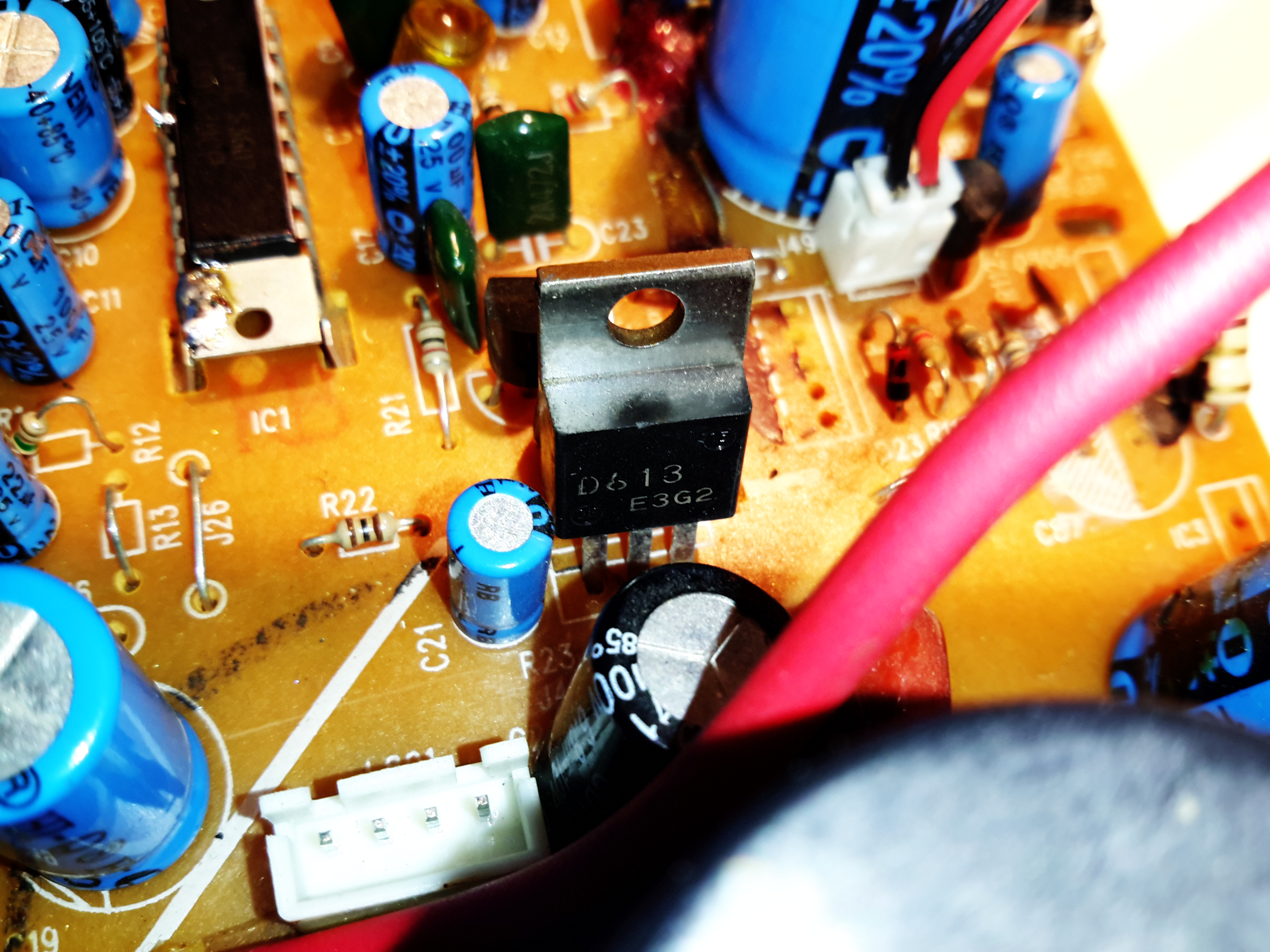
Horizontal Output Transistor
This is in fact the horizontal drive transistor, a 2SD613, which according to the datasheet, is intended for audio amplifier output stage applications, not CRT drive. Regardless, it’s an 85v 6A NPN transistor, and does get a bit on the warm side, but was never given a heatsink from the factory.
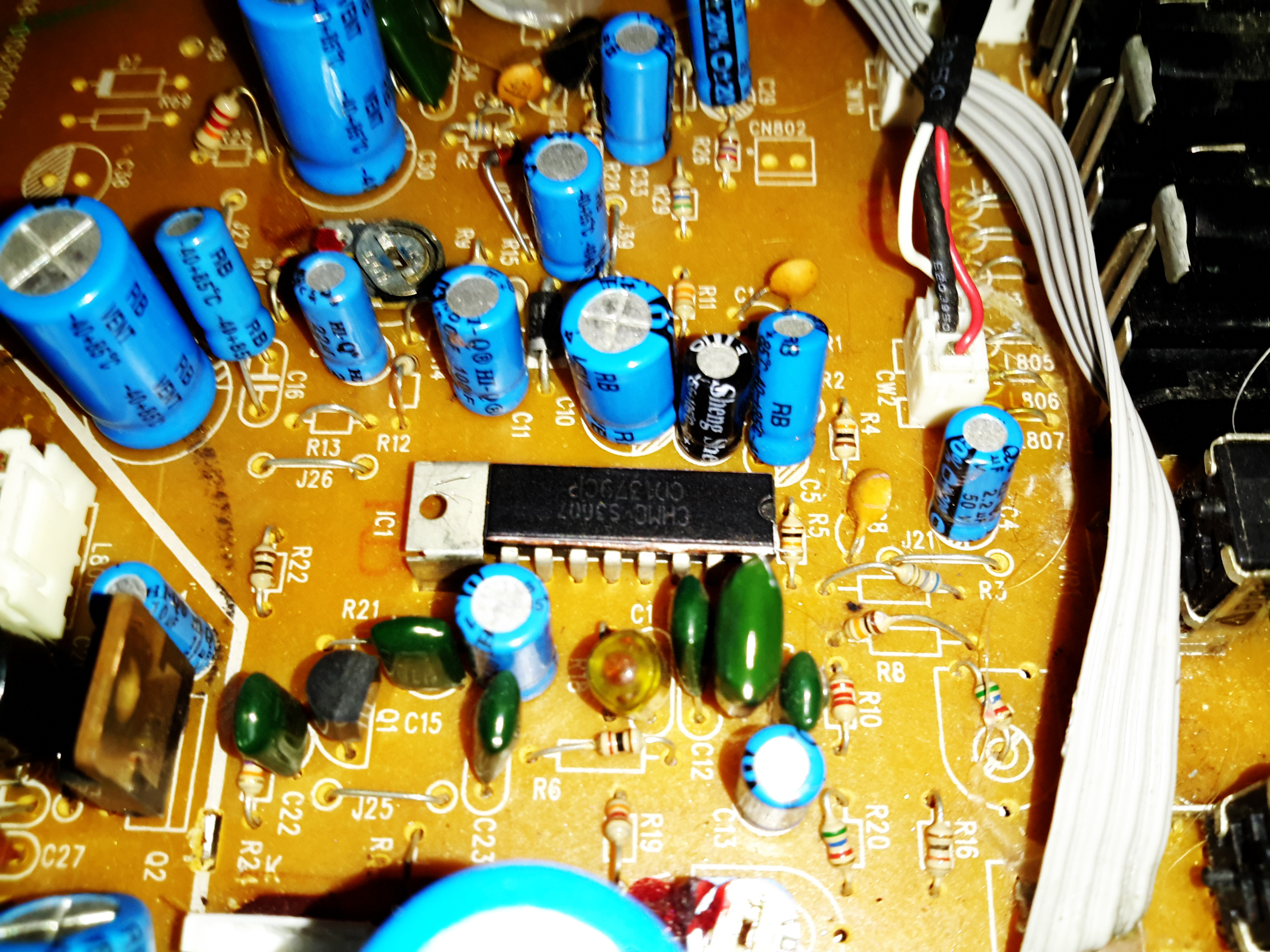
CRT Drive IC
All the drive signals for the CRT are taken care of by this single DIP IC – a CD1379CP from Silicore. Considering the older CRT-based devices I have, with entire boards twice the size of this one dedicated to discrete components required to drive a CRT, this is definitely an advance in technology. Very few external components are being used, and no custom magnetics.
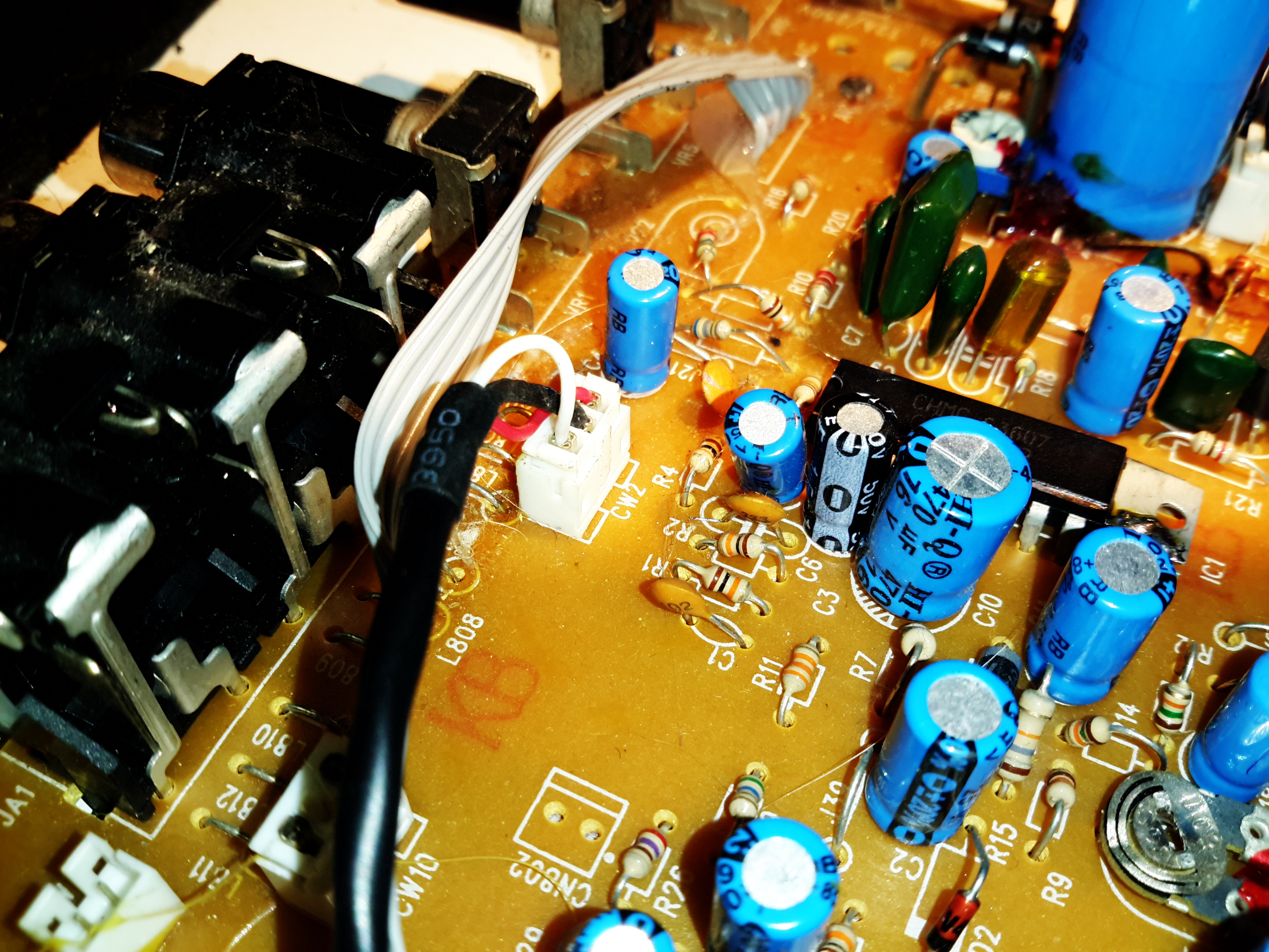
Video Input
The video signal comes in from the CD+G player module on this connector, it’s a standard composite input. The composite video is fed into an amplifier after the controller IC. This video amp is powered from a 140v rail from the flyback transformer, to give enough signal to drive the CRT cathode.
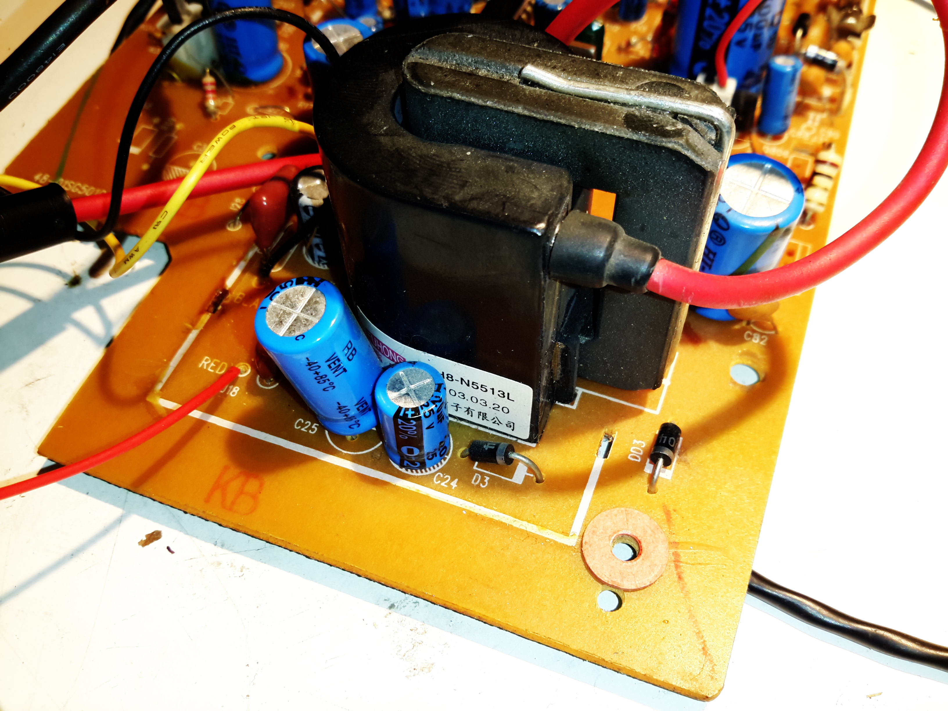
LOPT
The high voltage transformer is a BSH8-N5513L, I’ve not been able to find any data on this, but it looks like a standard off the shelf transformer from the listings on the Chinese supplier sites. There are very few support components around here, just a couple of diodes to rectify the high voltage focus supply, and no linearity coil. Weirdly, the 1st accelerating anode of the tube is grounded in this circuit. Very few adjustments are provided, most are set with fixed resistors to keep the cost low.
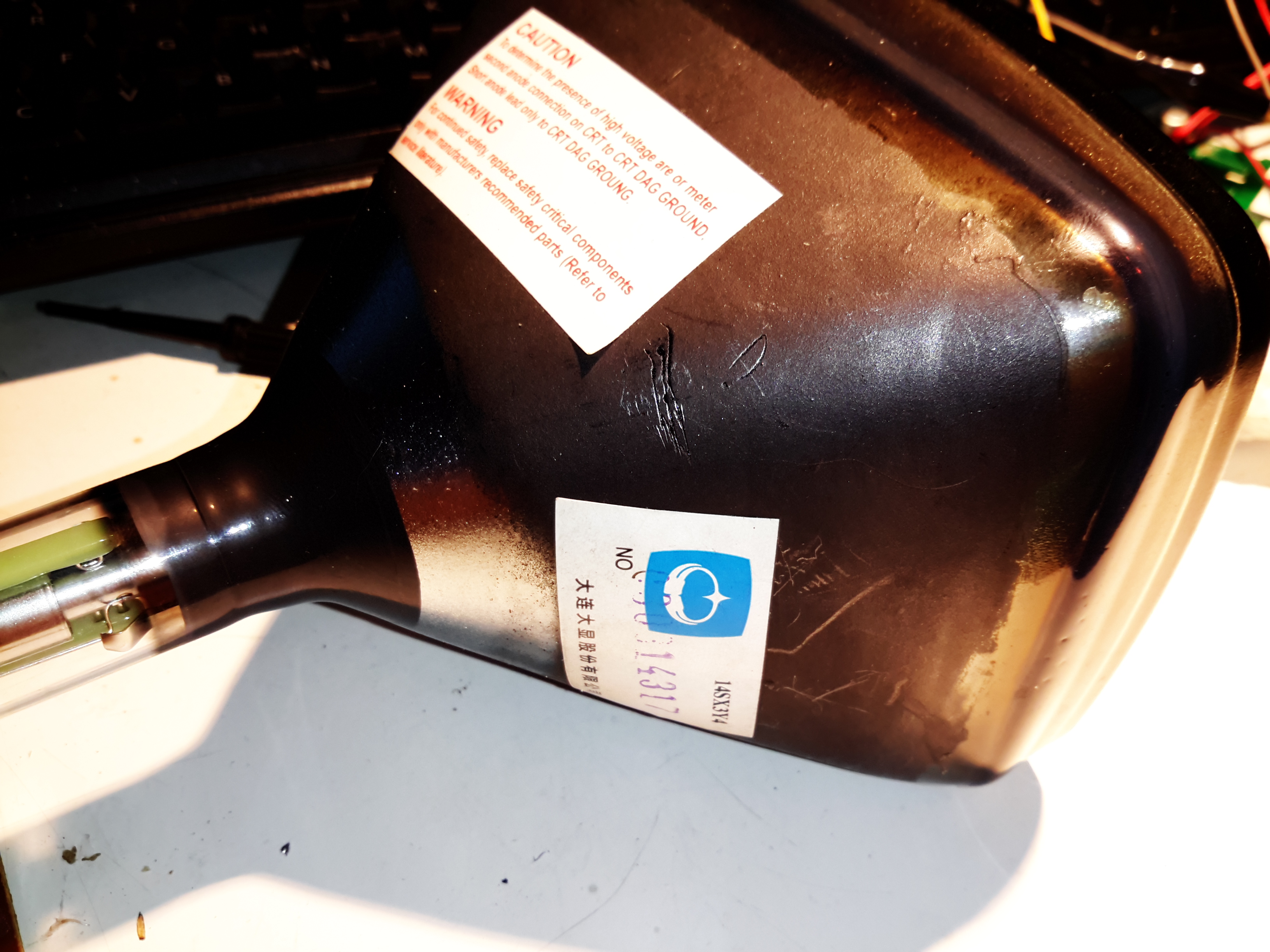
The CRT
14SX3Y4 CRT
Here’s the CRT, it’s a 5″ monochrome model. I’ve not been able to find much data on this either.
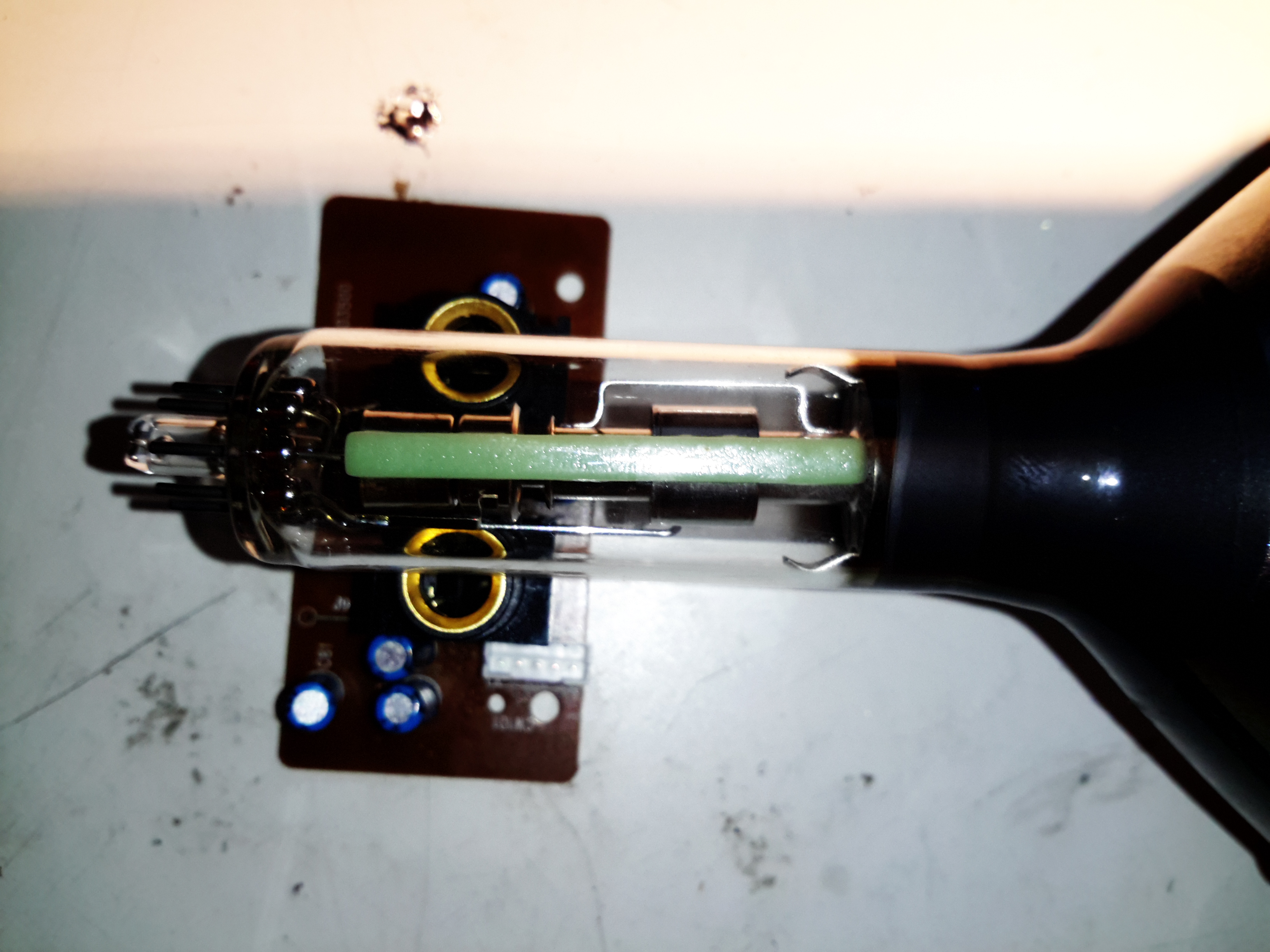
Bent Electron Gun
Seems the gents in the Shenzhen factory were having a bit of an off day when this one was made – the electron gun assembly is actually tilted in the neck of the tube – as a result the spot formed with no deflection is far from the centre of the screen. This tube does still produce a pretty good picture though, this manufacturing error is easily corrected for with the positioning magnets on the deflection yoke.
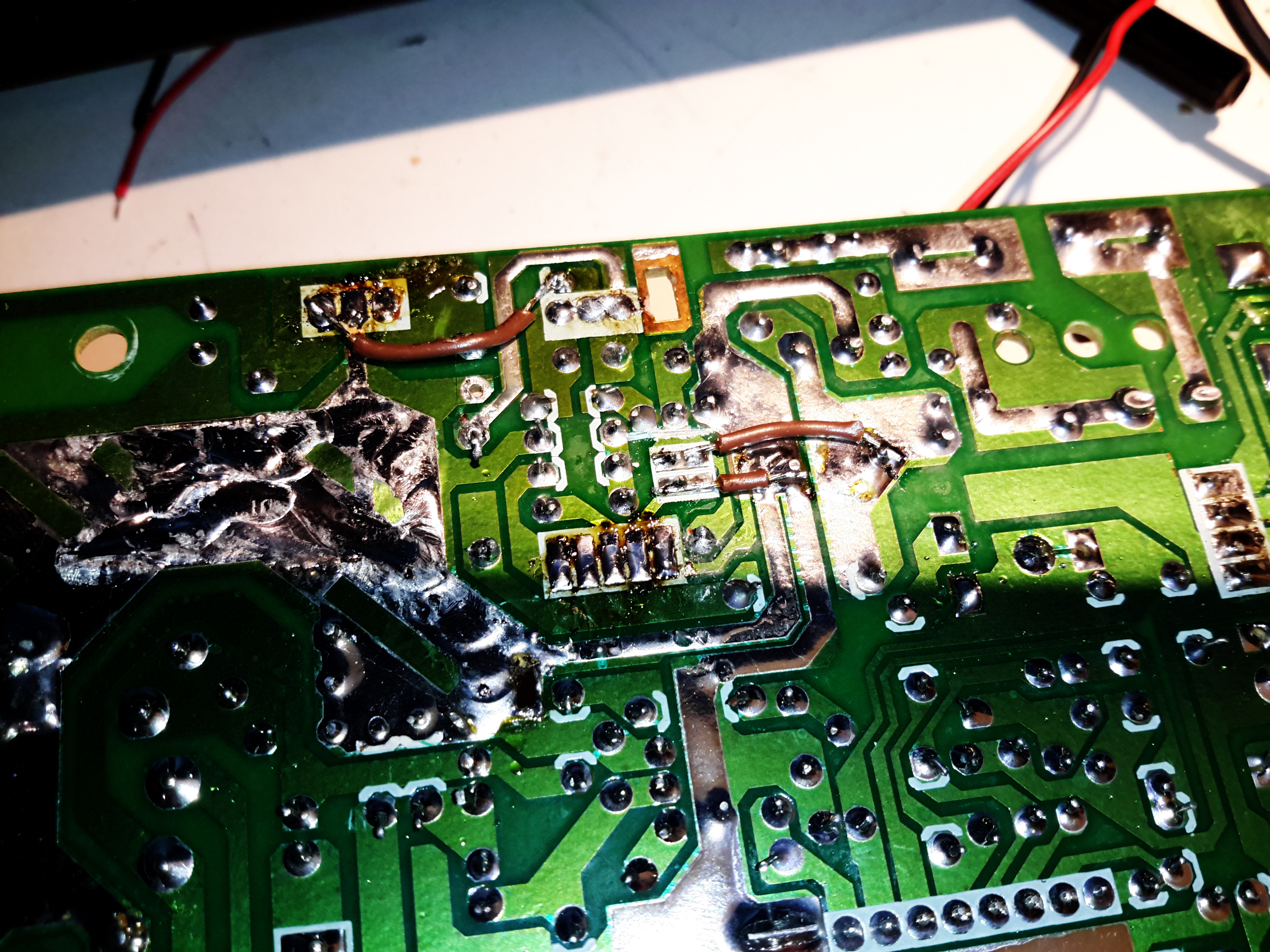
Final Mods
PCB Mods
I’ve installed a couple of mod wires on the bottom of the PCB to get this to work outside the original application, without the room heater of a linear regulator in circuit this will run fine from a 12v supply. The PCB quality is a bit naff – even quick heating with a soldering iron makes tracks fall off the laminated paper board.
Image Display
Image quality is surprisingly good for the cheapest CRT-based monitor I’ve ever seen, I figured a Fallout reference was required here; anyone for a proper CRT-based PipBoy? 😉 Shame the phosphor isn’t green.
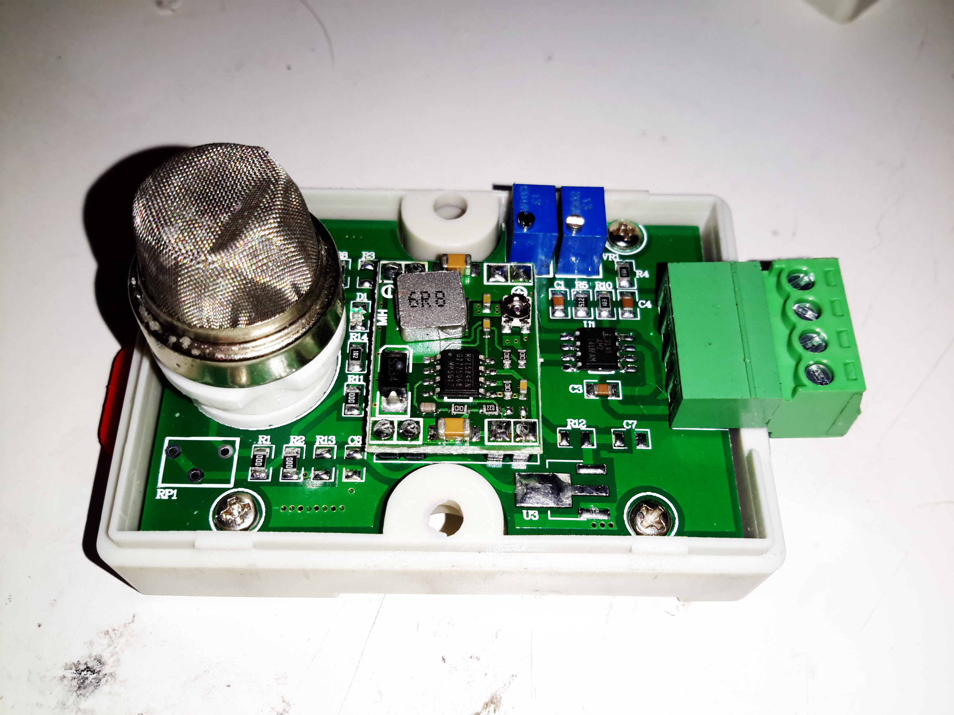
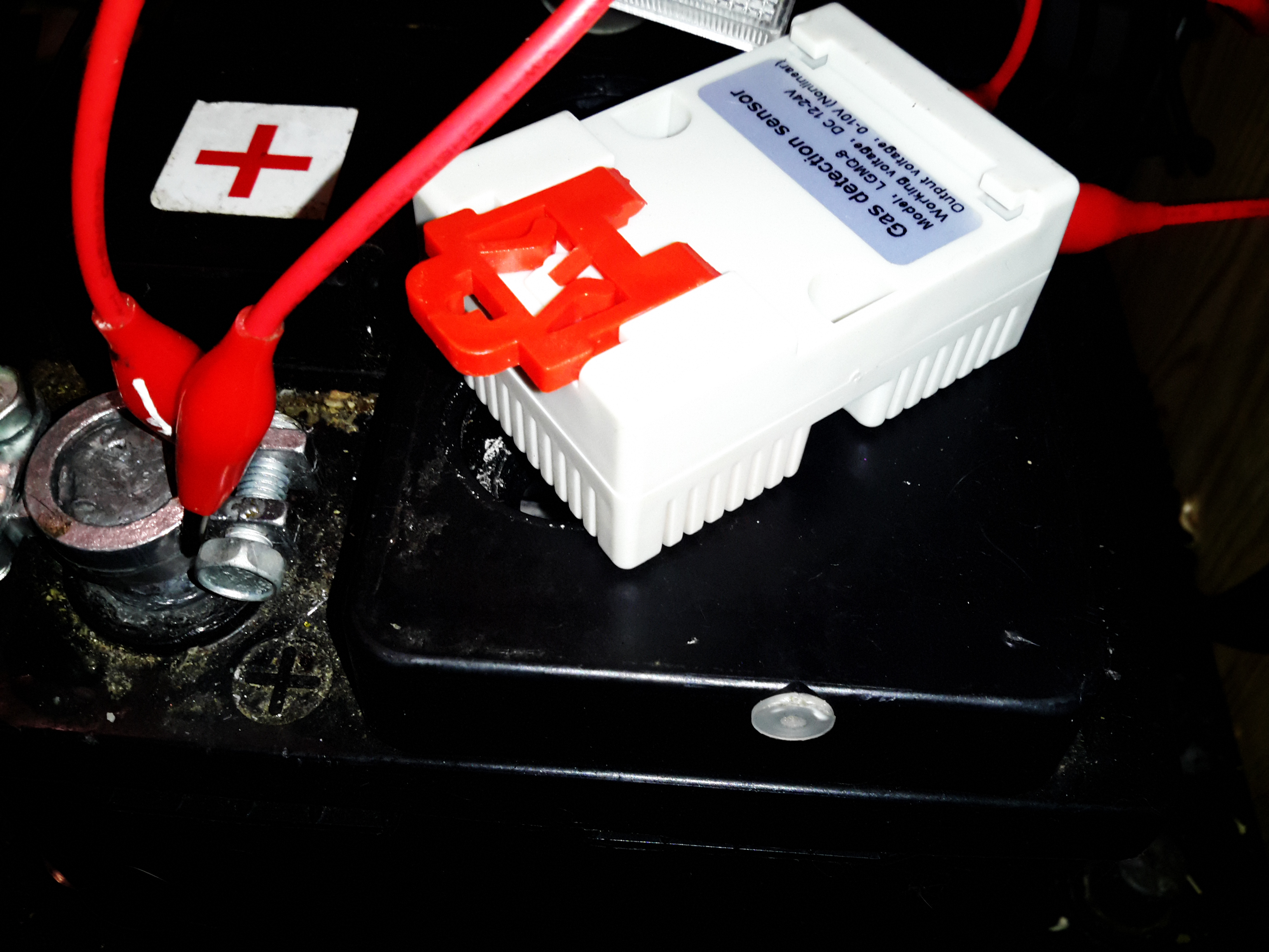
Since the batteries on board the boat are located in the cabin, I’ve noticed something rather odd with the Carbon Monoxide detectors: when the batteries are being charged, the CO alarms are triggering on the H² that’s being released. Since the last thing we need is hydrogen building up to levels that could become explosive (which for H² is a very wide range, from 4% to 75% in standard atmospheric conditions, it also has a very low activation energy), some venting of the battery compartment is required while the batteries are being float charged. These SnO² based sensors are very cheap, so I figured I’d give one of them a go.
This particular module has a DIN rail mounting clip on the back, along with holes to mount with screws. It’s signal output is standard industrial 0-10v.
Cover Removed
Popping the cover off reveals some adjustment pots, a DC-DC converter & a single amplifier on the output. The sensor itself is plugged into a ceramic socket, so this could be replaced in the future if needed.
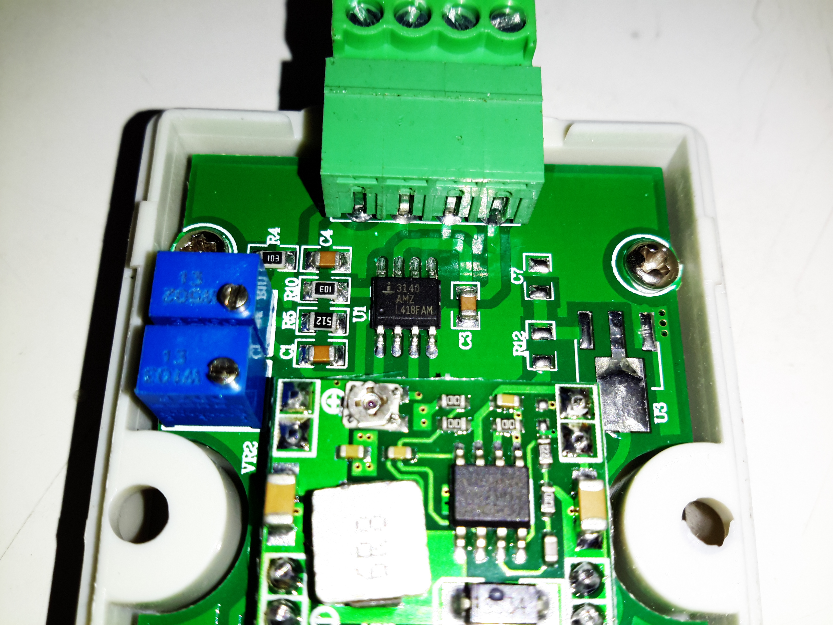
Output Amplifier
The output Op-Amp is an Intersil CA3140 4.5MHz BiMOS, with FET input & bipolar output stages.
Adjustment Pots
There’s a trio of potentiometers for adjusting the sensor.
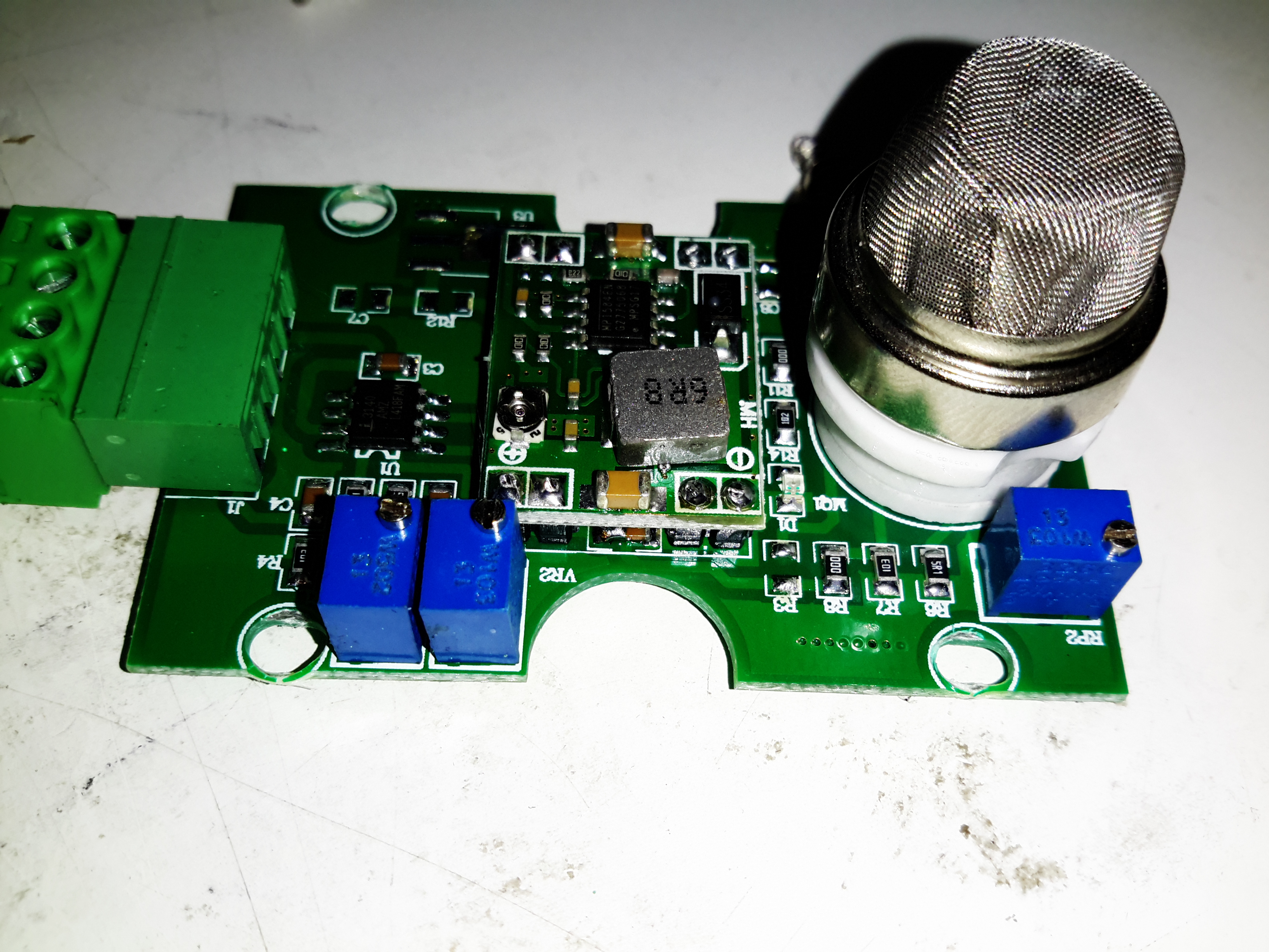
Potentiometer
Function
RP2
Sensor Load Resistance Adjust
VR1
Sensitivity Adjust
VR2
Ref. Voltage Adjust
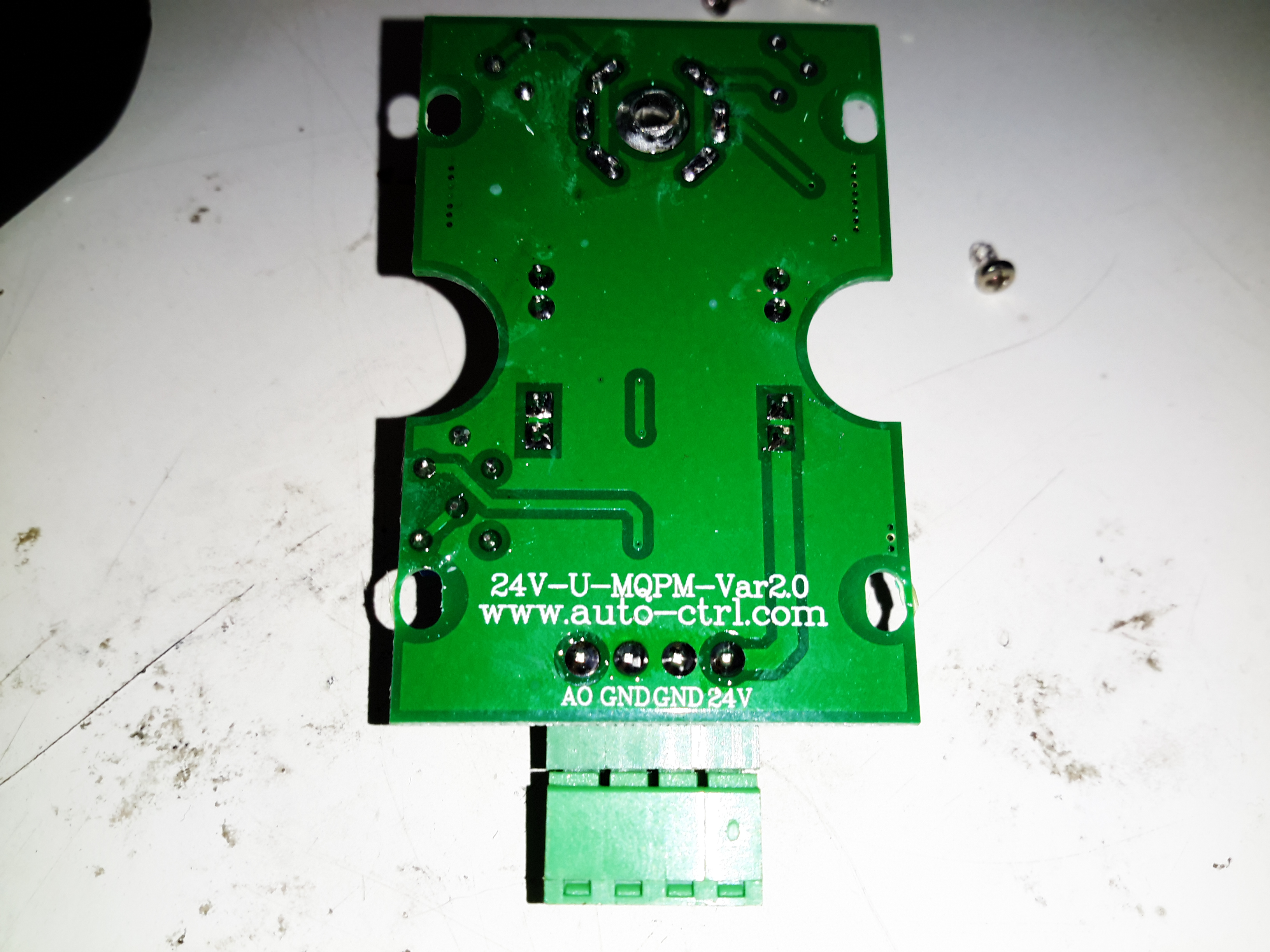
PCB Bottom
The bottom of the PCB is pretty sparse, but there’s a model number here & a website. The guys that make this seem to specialize in sensing modules.
Sensor In Cell
To give this unit a test, I removed the cell cap from one of my spare lead acids & placed the sensor head into the opening while I was giving it a topping charge. In this position any gas given off by the charging battery would instantly rise up into the sensor.
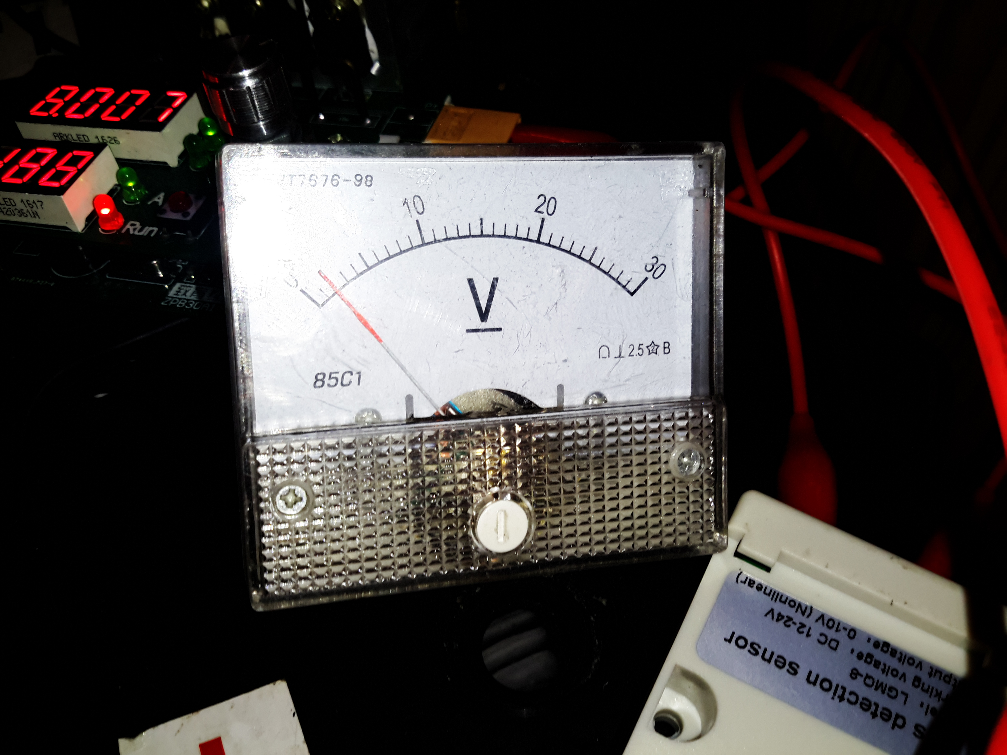
Output
Once the sensor has heated up & stabilised, the base voltage with no hydrogen present was about 1 volt. As the battery voltage rose to 13.2v the sensor began to detect some hydrogen, with the voltage rising to about 9 volts with the battery voltage at topping charge level of 14.4v.
These sensors definitely work, but there’s no calibration so it’s not possible to say how much gas is present, but this isn’t a problem for my application.
More to come when the ventilation system is installed in the battery compartment!
After I did the voltage mod on the APS-231 PSU power supply, I did some reading online & discovered there’s a more powerful PS3 supply – the APS-227. This beast has a 32A +12v rail, with a 3A +5v standby rail.
Specifications
As far as I can tell, these are used in another version of the PS3, obviously with a chunkier requirement for 12v DC.
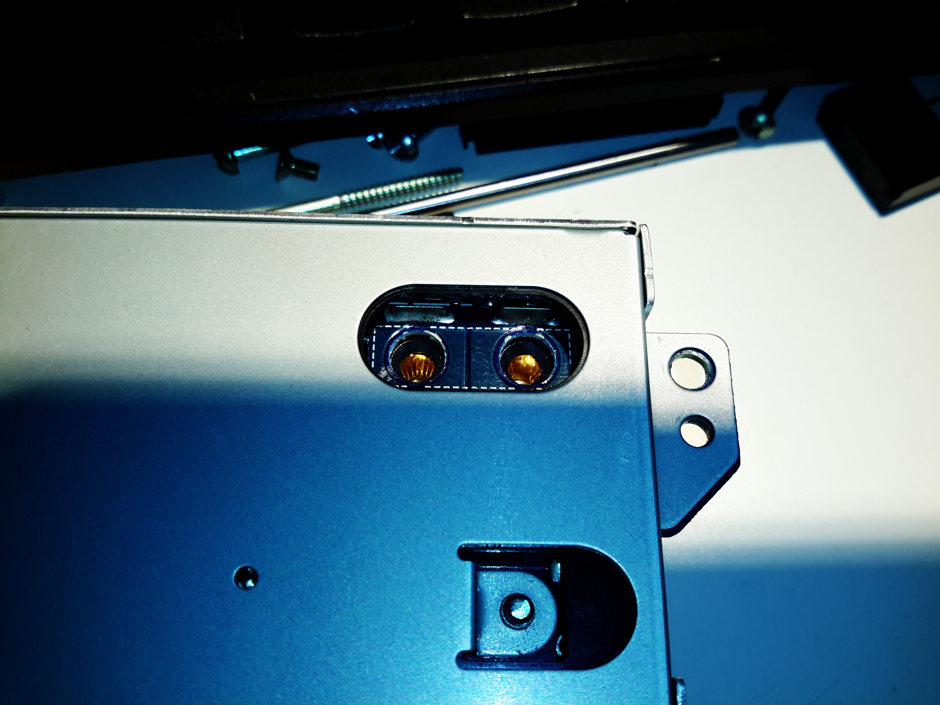
DC Output
The main DC rail appears through the same type of connector as the smaller supply, which is compatible with standard banana plugs.
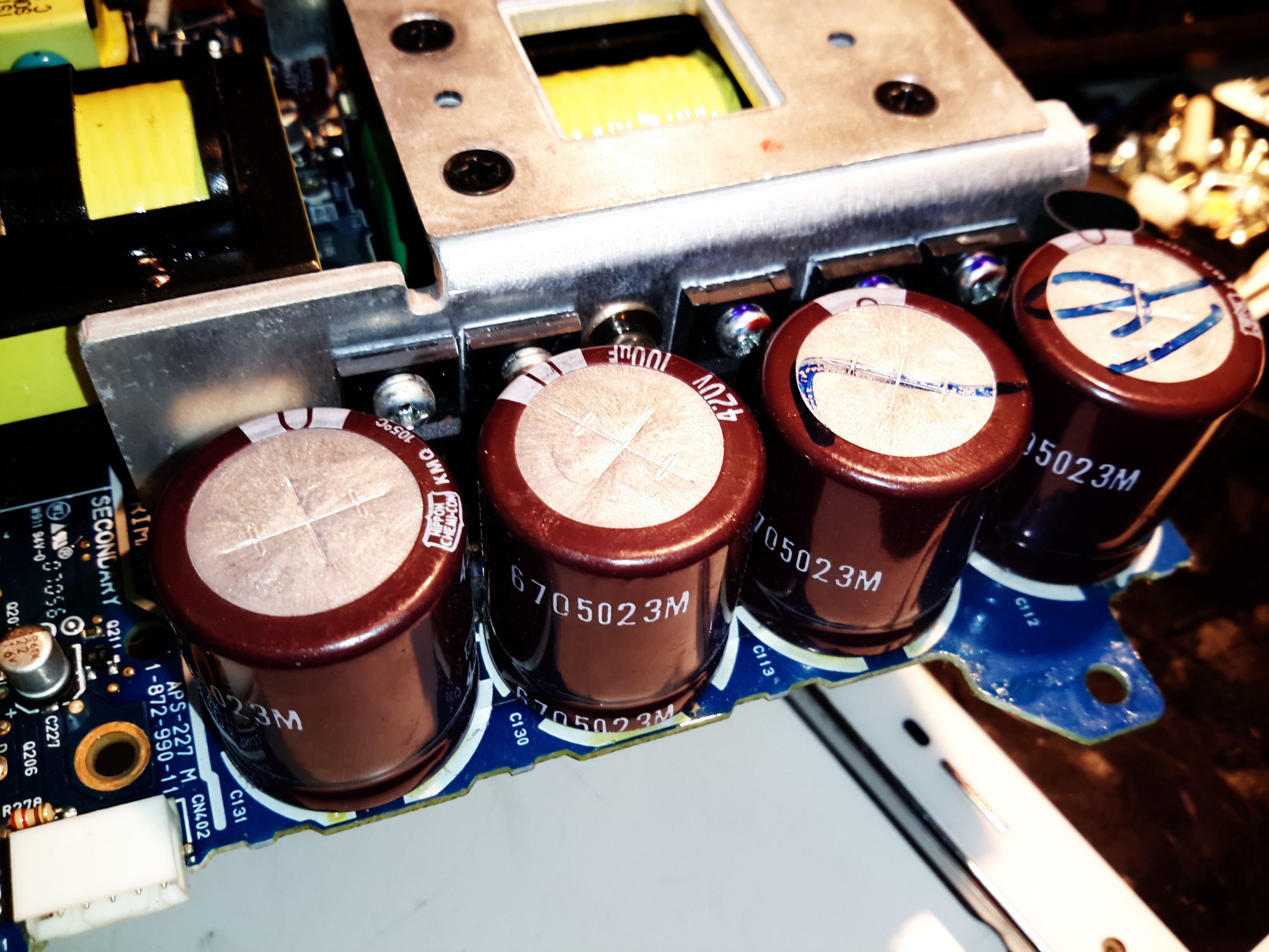
HV DC Bus Capacitors
These PSUs are very high build quality, Nichcon electrolytics are used all over the place. These are the HV DC rail filter caps, rated at 100µF 420v.
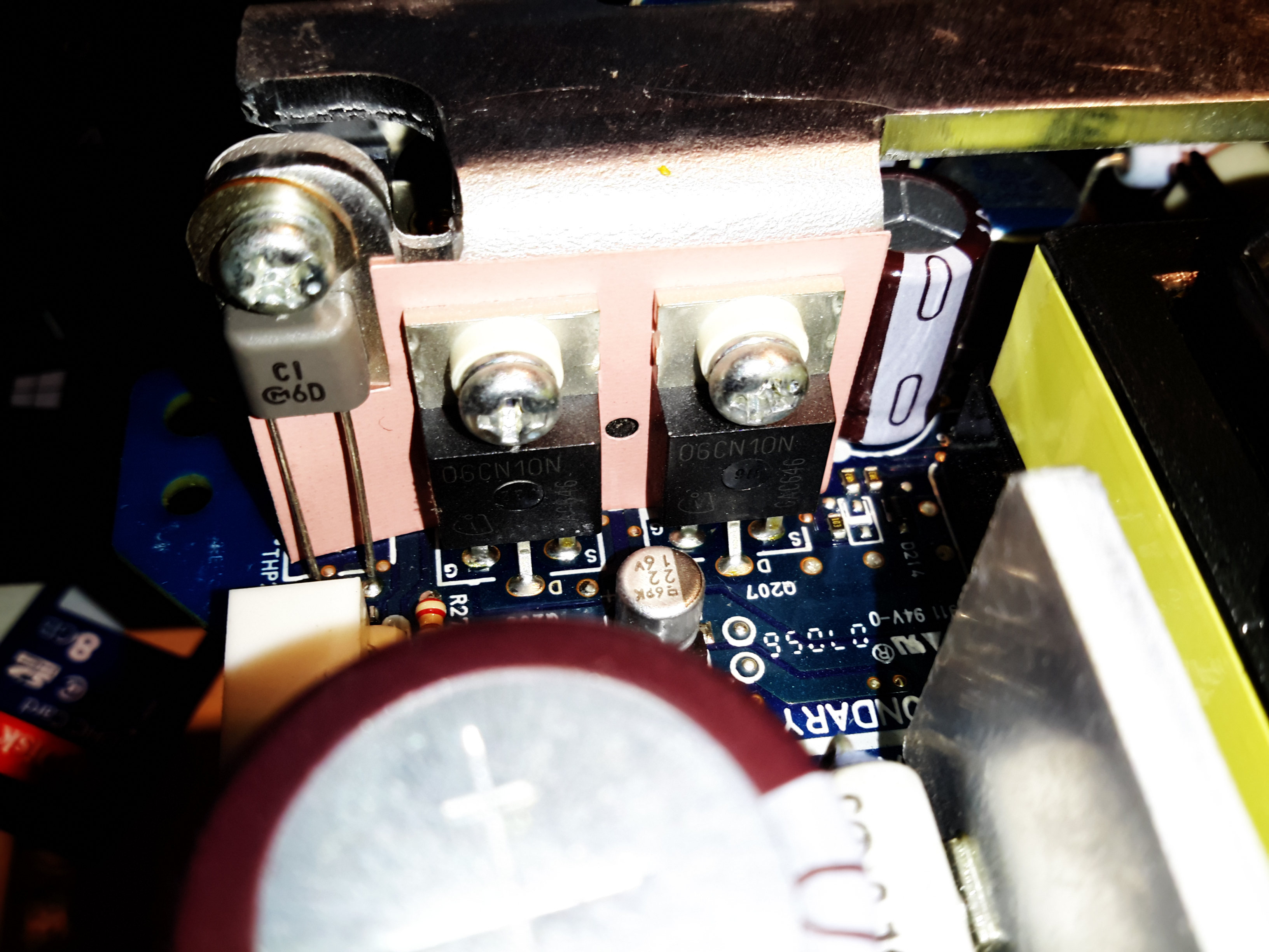
Output Synchronous FETs
Synchronous rectification is also used in these supplies, keeping the waste heat down to a minimum on the output rectification. There’s a thermistor on the heatsink to the left for the thermal protection.
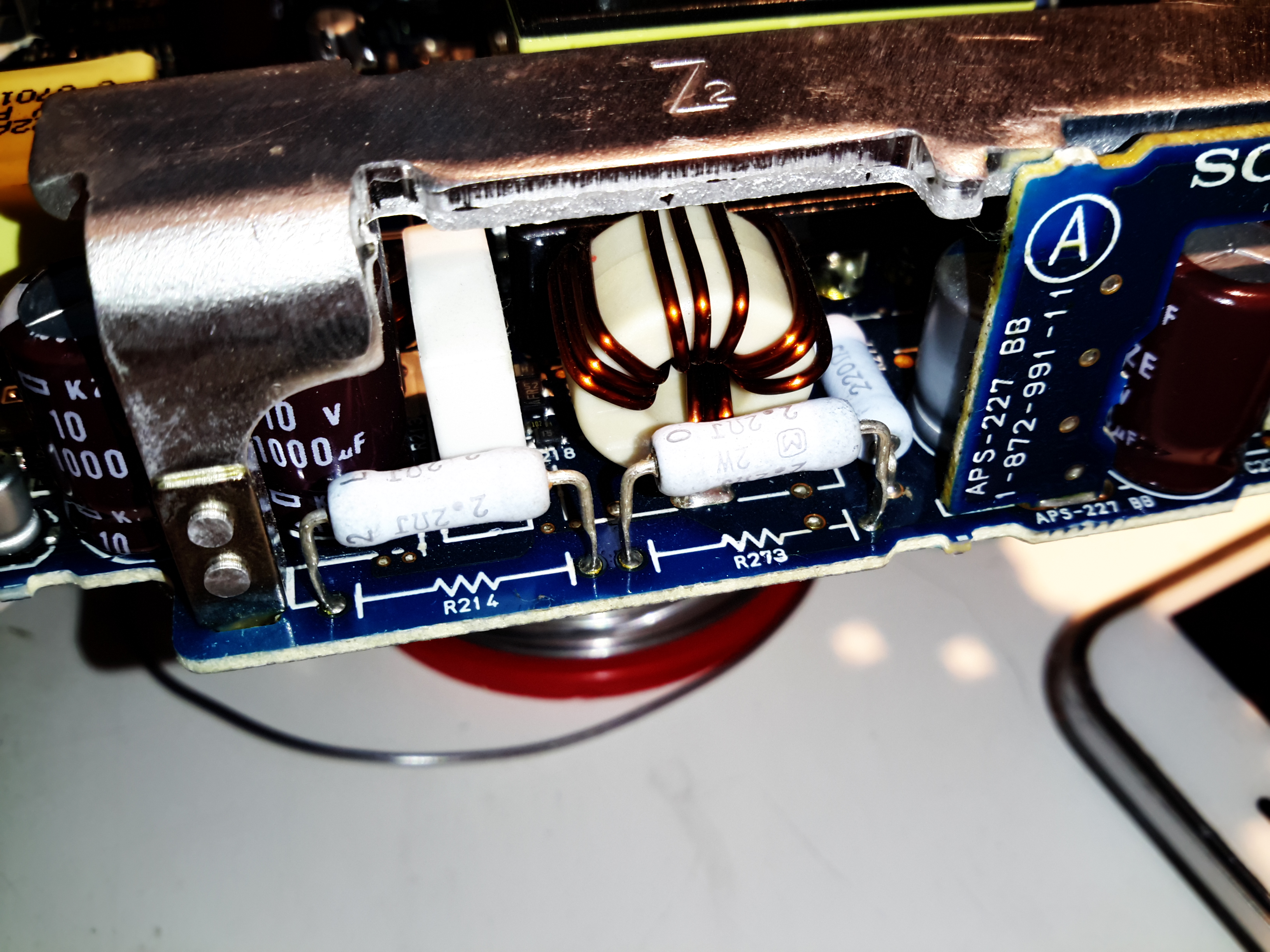
+12v Rail Load Resistors
A couple of 2.2Ω resistors in series provide a minimum load to the PSU to keep things stable at low power. Adjusting the output too high will likely cause these resistors to overheat.
Transformer
The main transformer has a huge secondary winding, only 4 turns of Litz type wire, about 5mm².
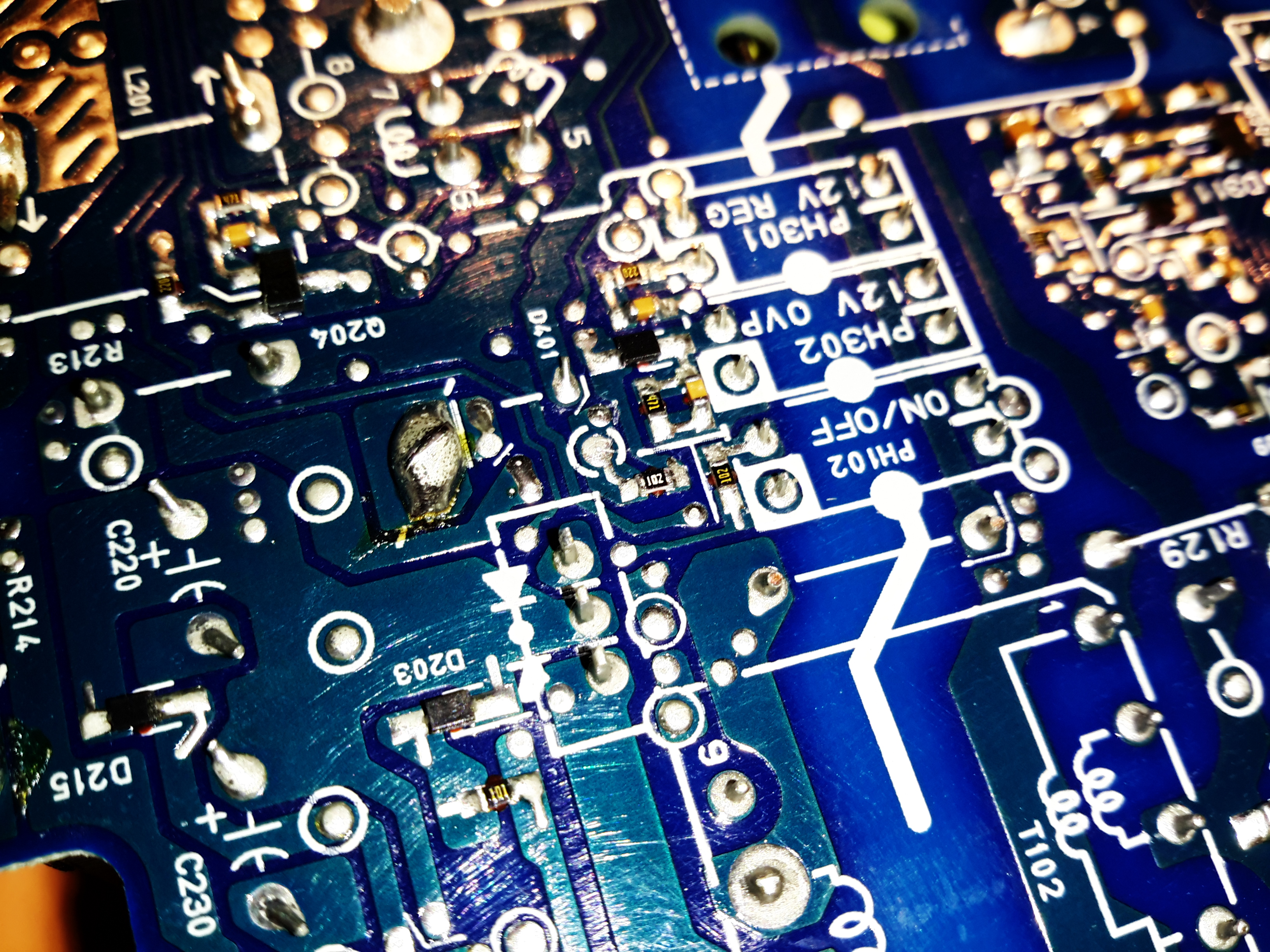
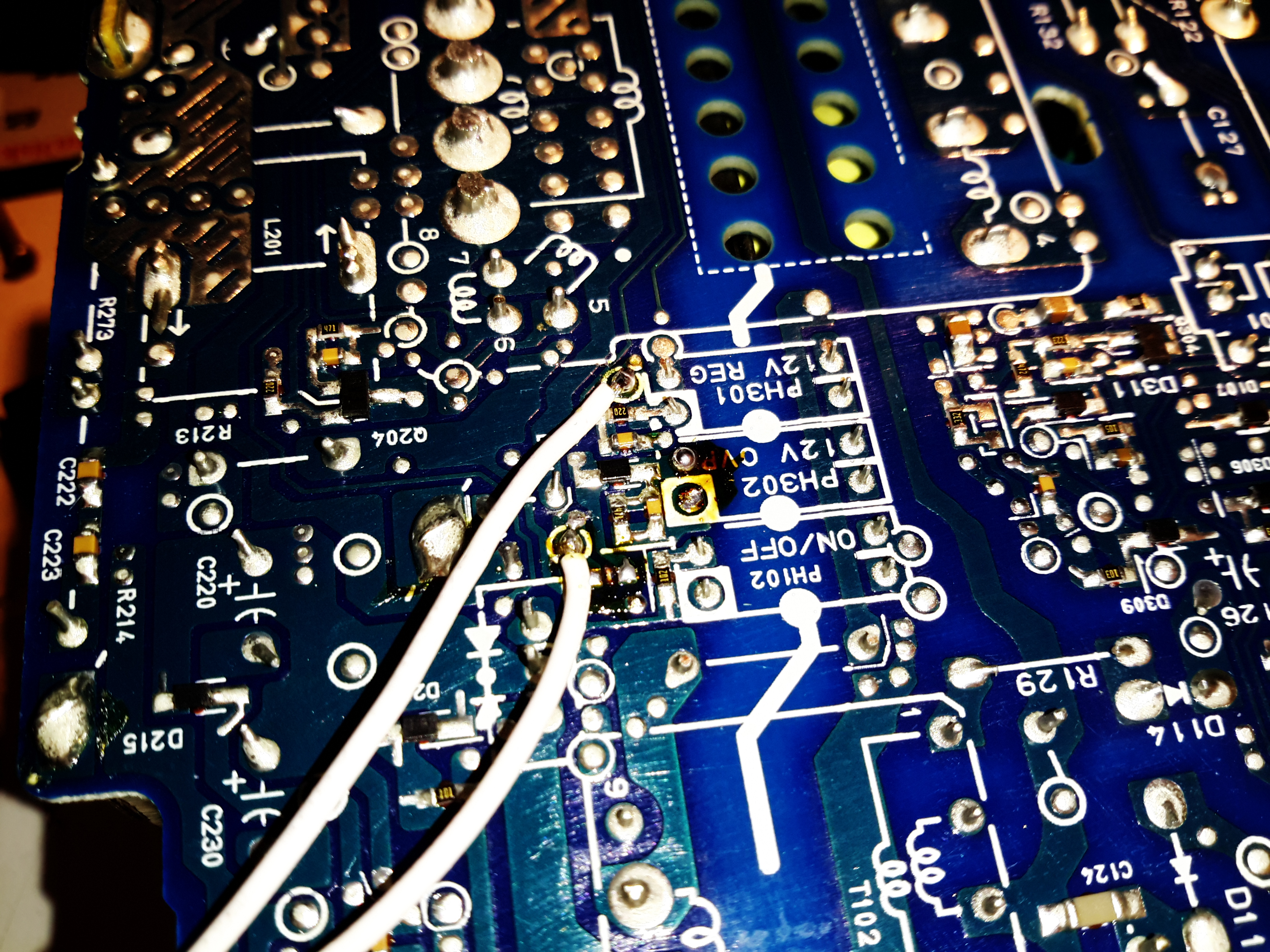
Regulator Section
Here’s the point where the mod needs to be done – the same as the other PS3 supply, a single resistor needs changing for a potentiometer, it’s the 1KΩ one in the center of the photo. (White “102” text on the top, unlike the others which are yellow). Desolder this 0402 resistor.
Mod Wires
After the resistor is removed, solder the mod wires to these test points.
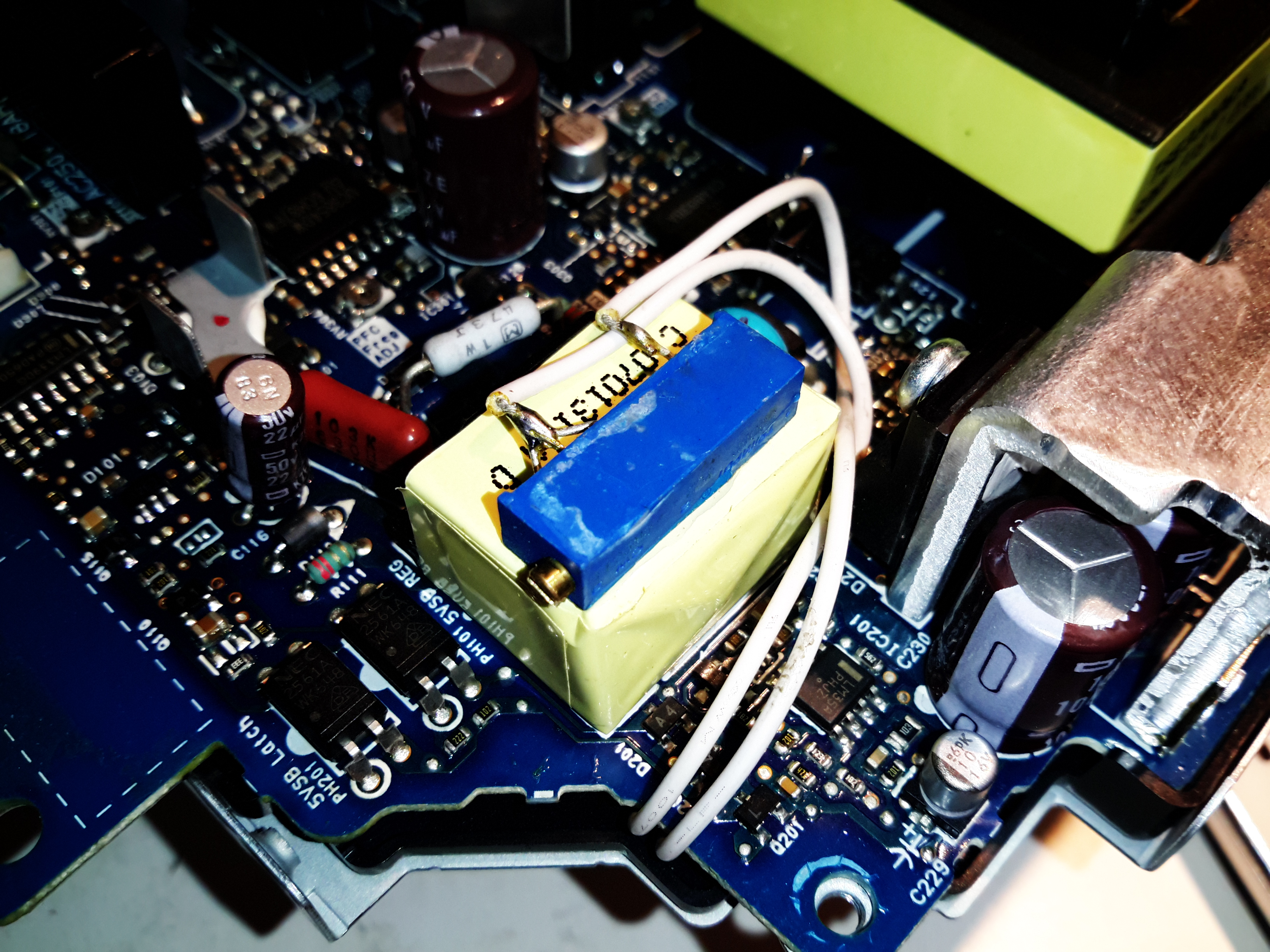
Mod Pot
Just like the APS-231, a 1KΩ 18-turn potentiometer is used to tweak the voltage. I’ve secured it with a drop of CA glue to the top of the standby transformer.
OVP Optocoupler Disconnected
The overvoltage protection on this supply is a little more aggressive – tripping things out at 13.4v. However it’s easy to defeat this on this particular supply, by disconnecting the “12V OVP” optocoupler from the secondary side. This does leave the supply with no active overvoltage protection, so be careful on how far the voltage gets tweaked up! The output electrolytics are rated at 16v, so there’s the potential for ballistic capacitors if things are tweaked too far!
Since I’ve been working on the backend servers a lot over the past few days, I’ve decided it was time to get some broken things on the blog fixed.
Firstly, the radiation monitor graphs. Originally I was using a Raspberry Pi to grab the data from the local monitor, and that was connecting via FTP to the server over in the datacentre to push it’s graph images. Since the server is now on the same local network as the monitor, there’s no need to faff about with FTP servers, so I’ve rejigged things with some perl scripts from cristianst85 over on GitHub, running on the web server itself.
I deviated from the suggested place to put the scripts on the server & opted to store everything within the Experimental Engineering hosting space, so it gets backed up at the same time as everything else on a nightly basis.
powered by Advanced iFrame
This is also accessible from the menu at top left, the script pulls data from the monitor & updates the images every 60 seconds via a cron job.
I’ve removed a couple of dead pages from the blog system, along with some backend tidying of the filesystem. Over the years things have gotten quite messy behind the scenes. This blog is actually getting quite large on disk, I’ve hit the 15GB mark, not including the database!
Caching is enabled for all posts on the blog now, this should help speed things up for repeat visitors, but as most of my content is (large) image based, this might be of limited help. I’m currently tuning the MySQL server for the load conditions, but this takes time, as every time I change some configuration settings I have to watch how things go for a few days, before tweaking some more.
Server Control Panels – More Of The Same
Sorry Sentora. I tried, and failed to convert over to using it as my new server control panel. Unfortunately it just doesn’t give me the same level of control over my systems, so I’ll be sticking with Virtualmin for the foreseeable future. Sentora stores everything in, (to me at least), very odd places under /var/ and gave me some odd results with “www.” versions of websites – some www. hosts would work fine, others wouldn’t at all & just redirect to the Sentora login interface instead. This wasn’t consistient between hosting accounts either, and since I didn’t have much time to get the migration underway, this problem was the main nail in the coffin.
Just storing everything under the sun in /var/ makes life a bit more awkward with the base CentOS install, as it allocates very little space to / by default, (no separate /var partition in default CentOS), giving most of the disk space to /home. Virtualmin on the other hand, stores website public files & Maildirs under /home, saving /var for MySQL databases & misc stuff.
The backup system provided is also utterly useless, there’s no restore function at all, and just piles everything in the account into a single archive. By comparison, Virtualmin has a very comprehensive backup system built in, that supports total automation of the process, along with full automatic restore functionality for when it’s needed.
Sentora did have some good points though:
It handled E-Mail logins & mail filters much more gracefully than Virtualmin does, and comes with Roundcube already built into the interface ready to use. With Virtualmin the options are to use the Usermin side of the system for E-Mail, which I find utterly awful to use, or install a webmail client under one of the hosted domains (my personal choice).
Mail filtering is taken care of with Sieve under Sentora, while Procmail does the job under Virtualmin.
Sentora does have a nicer, simpler, more friendly interface, but it hides most of the low-level system stuff away, while under Virtualmin *everything* on the system is accessible, and it provides control interfaces for all the common server daemons.
This was originally going to be part of another post, but it ended up getting more complex than I originally intended so it’s been given it’s own. I go into into many of my personal security practices, on both my public facing servers & personal machines. Since the intertubes are so central to life these days, good security is a must, especially since most people use the ‘net to do very sensitive operations, such as banking, it’s becoming even more essential to have strong security.
Since bringing the new server online & exposing it to the world, it’s been discovered in record time by the scum of the internet, SSH was under constant attack within 24 hours, and within that time there were over 20,000 failed login attempts in the logs.
This isn’t much of an issue, as I’ve got a strong Fail2Ban configuration running which at the moment is keeping track of some 30 IP addresses that are constantly trying to hammer their way in. No doubt these will be replaced with another string of attacks once they realise that those IPs are being dropped. I also prevent SSH login with passwords – RSA keys only here.
MySQL is the other main target to be concerned about – this is taken care of by disabling root login remotely, and dropping all MySQL traffic at the firewall that hasn’t come from 127.0.0.1.
Keeping the SSH keys on an external device & still keeping things simple just requires some tweaking to the .bashrc file in Linux:
alias ssh='ssh -i <Path To Keys>'
This little snippet makes the ssh client look somewhere else for the keys themselves, while keeping typing to a minimum in the Terminal. This assumes the external storage with the keys always mounts to the same location.
Everything else that can’t be totally blocked from outside access (IMAP, SMTP, FTP, etc), along with Fail2Ban protection, gets very strong passwords, unique to each account, (password reuse in any situation is a big no-no) and where possible TOTP-based two factor authentication is used for front end stuff, all the SSH keys, master passwords & backup codes are themselves kept offline, on encrypted storage, except for when they’re needed. General password management is taken care of by LastPass, and while they’ve been subject to a couple of rather seriousvulnerabilities recently, these have been patched & it’s still probably one of the best options out there for a password vault.
There’s more information about those vulnerabilities on the LastPass blog here & here.
This level of security paranoia ensures that unauthorized access is made extremely difficult – an attacker would have to gain physical access to one of my mobile devices with the TOTP application, and have physical access to the storage where all the master keys are kept (along with it’s encryption key, which is safely stored in Meatware), to gain access to anything.
No security can ever be 100% perfect, there’s always going to be an attack surface somewhere, but I’ll certainly go as far as is reasonable, while not making my access a total pain, to keep that attack surface as small as possible,and therefore keeping the internet scum out of my systems.
The last layer of security is a personal VPN server, which keeps all traffic totally encrypted while it’s in transit across my ISP’s network, until it hits the end point server somewhere else in the world. Again, this isn’t perfect, as the data has to be decrypted *somewhere* along the chain.
Since Sentora is still stuck on an old version of PHP, this script will update the system to the newer v5.6, via the Remi repository, as most things are deprecating support for older PHP versions at this point. Suhosin will also be recompiled for the new PHP version.
#!/bin/bash

echo "Upgrading PHP to version 5.6. Please Wait..."

wget http://rpms.famillecollet.com/enterprise/remi-release-7.rpm
sudo rpm -Uvh remi-release-7*.rpm

yum update

yum --enablerepo=remi,remi-php56 update
yum --enablerepo=remi,remi-php56 upgrade

echo "Recompiling Suhosin for PHP 5.7..."

cd /tmp
wget -nv -O suhosin.zip https://github.com/stefanesser/suhosin/archive/suhosin-0.9.37.zip
unzip -q suhosin.zip
rm -f suhosin.zip
cd suhosin-suhosin-0.9.37
phpize &> /dev/null
./configure &> /dev/null
make &> /dev/null
make install
cd ..
rm -rf suhosin-suhosin-0.9.37

echo "Restarting Web Server Services..."

systemctl restart httpd
The Remi repo will give some package authentication warnings, these can be safely dismissed during the install. I’ve tested this on a fresh install of Sentora under CentOS 7, however this process isn’t without risk! Your PHP install could be damaged!
I’m making some changes to my hosting services, I’ve been testing Sentora, as it’s much more user friendly, if a little more limited in what it’s capable of doing, vs my go-to admin panel over the past 6+ years, Virtualmin.
I noticed that SpamAssassin isn’t set up on a Sentora server by default, so here’s a script that will get things working under a fresh Sentora install in CentOS 7:
After this script has run, some mail server settings will be changed, and the master.cf configuration file for Postfix will be backed up just in case it craps out.
Make sure the SpamAssassin daemon is running on port 783 with this command:
ss -tnlp | grep spamd
Testing is easy, send an email to an address hosted by Sentora with the following in the subject line:
If SpamAssassin is working correctly, this will be tagged with a spam score of 999.
A useful script is below, this trains SpamAssassin on the mail in the current server mailboxes. I’ve been using a version of this for a long time, this one is slightly modified to operate with Sentora’s vmail system. All mail for all domains & users will be fed into SpamAssassin in this script. I set this to run nightly in cron.
#!/bin/bash

#specify one or more users, space padded [user=(user1 user2 user3)] or empty [user=()] to include all users. All users is considered uid ≥ 1000.
user=(vmail)

#After how many days should Spam be deleted?
cleanafter=30

#backup path, comment out to disable backups
bk=/home/backup/sa-learn_bayes_`date +%F`.backup

log=/var/log/train-mail.log
#log=/dev/stdout

echo -e "\n`date +%c`"  >> $log 2>&1

if [ -z ${user[@]} ]; then
echo user is empty, using all users from system
user=(`awk -F':' '$3 >= 1000 && $3 < 65534' /etc/passwd |awk -F':' '{print $1}'`)
fi

for u in ${user[@]}; do
if [ ! -d /var/sentora/vmail/*/* ]; then
echo "No such Maildir for $u" >> $log 2>&1
else
echo "Proceeding with ham and spam training on user \"$u\""
#add all messages in "junk" directory to spamassassin
echo spam >> $log 2>&1
#change this path to match your spam directory, in this case its "Junk"
#add current and new messages in Junk directory as spam
sa-learn --no-sync --spam /var/sentora/vmail/*/*/.Junk/{cur,new} >> $log 2>&1
echo ham >> $log 2>&1
#only add current mail to ham, not new. This gives user a chance to move it to spam dir.
sa-learn --no-sync --ham /var/sentora/vmail/*/*/{cur} >> $log 2>&1
fi
done

#sync the journal created above with the database
echo sync >> $log 2>&1
sa-learn --sync >> $log 2>&1
if [ $? -eq 0 ]; then
for u in ${user[@]}; do
echo "deleting spam for $u older than 30 days" >> $log 2>&1
find /var/sentora/vmail/*/*/.Junk/cur/ -type f -mtime +$cleanafter -exec rm {} \;
done
else
echo "sa-learn wasn't able to sync. Something is broken. Skipping spam cleanup"
fi

echo "Statistics:" >> $log 2>&1
sa-learn --dump magic >> $log 2>&1
echo ============================== >> $log 2>&1

if [ -n $bk ]; then
echo "backup writing to $bk" >> $log 2>&1
sa-learn --backup > $bk
fi
I posted a while back a teardown of the VM Superhub 2 router, as VM has “upgraded” to a rebranded Arris TG2492S/CE CM. Alas Virgin Media in their wisdom have decided that simple router features like being able to change the LAN subnet & DHCP server range are far too complex to trust to the Great Unwashed, so they’ve removed them entirely from the firmware, and locked the local LAN onto the 192.168.0.0/24 range.
As my network is already numbered in the 10.0.0.0/16 range, with several statically addressed devices present and other systems relying on these static assignments, using this router would have meant renumbering everything.
Luckily Virgin had the decency to leave the “modem mode” option in the firmware, effectively disabling the WiFi & routing functions & allowing the connection of a third-party router. Some searching for a suitable replacement for the core of my network turned up the Linksys WRT1900ACS. While I waited for this to arrive, some temporary workarounds were needed to make everything function well enough with VM’s crap router.
WRT1900ACS
These routers have been designed as a modern replacement for the venerable WRT54G series of routers from some time ago, with full support for OpenWRT/DD-WRT firmware, and with a beefy 1.6GHz dual core CPU & 512MB of RAM I doubt I’ll be able to knock this one over with too much network traffic! This was pretty much the most powerful router I could afford, and should mean I don’t need to upgrade for a long time. (No teardown of this yet, as it’s taking care of the network at present. Maybe some point in the future I’ll take the plunge).
The stock firmware isn’t totally awful, and has some nice features, but I decided it needed to be replaced with DD-WRT for more security & future flexibility. I’ll leave the firmware flashing stuff for another post 😉
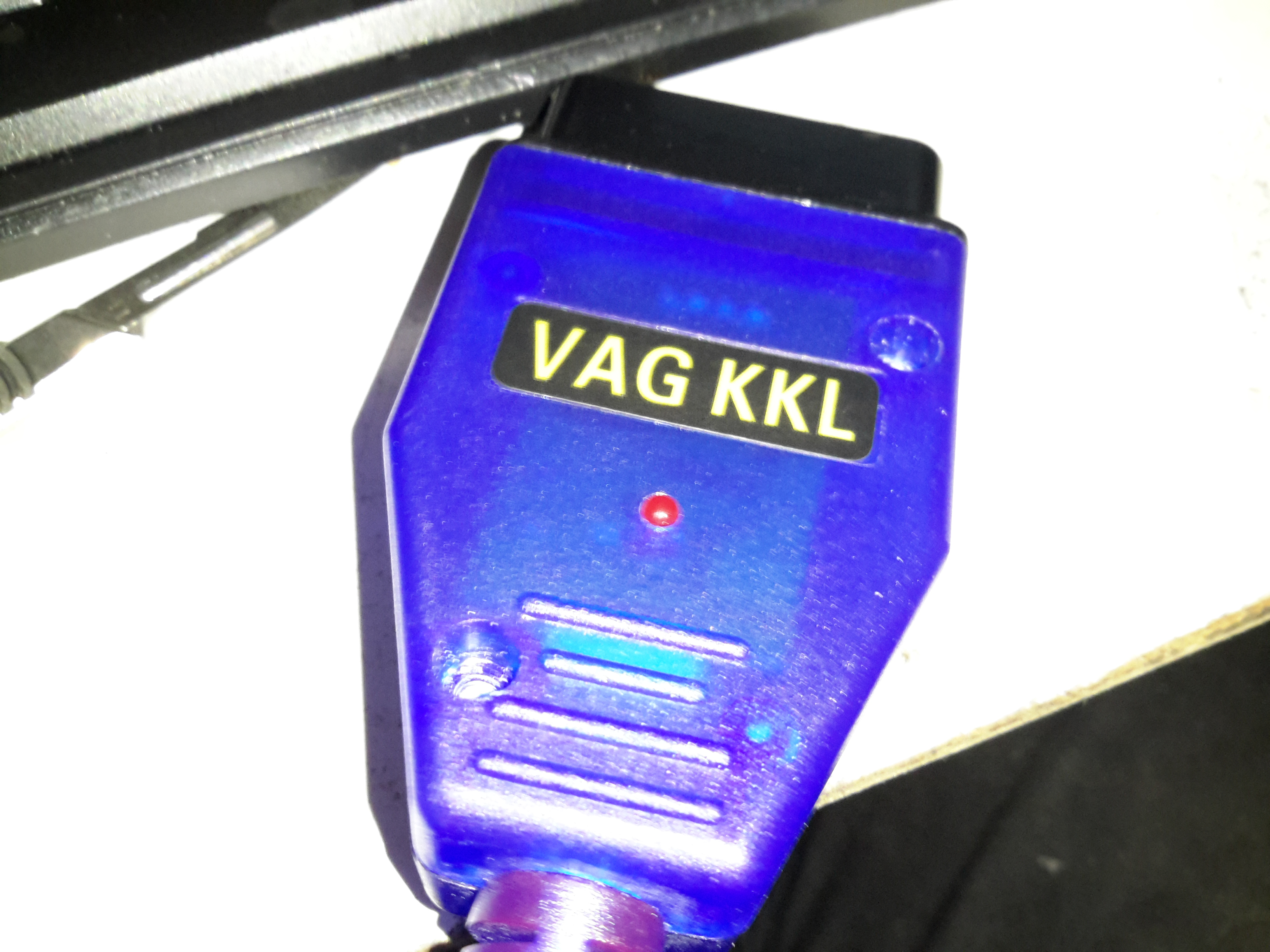
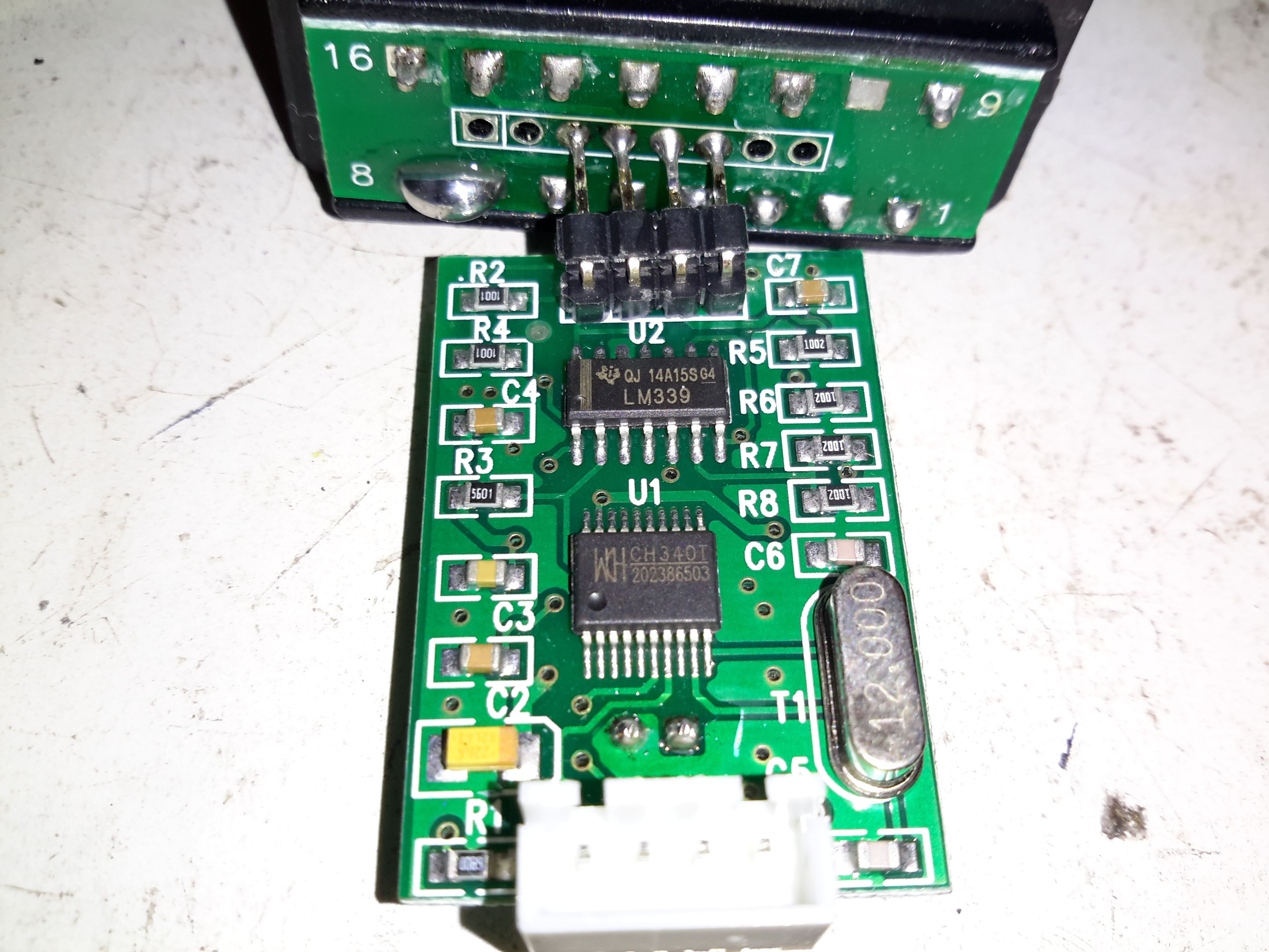
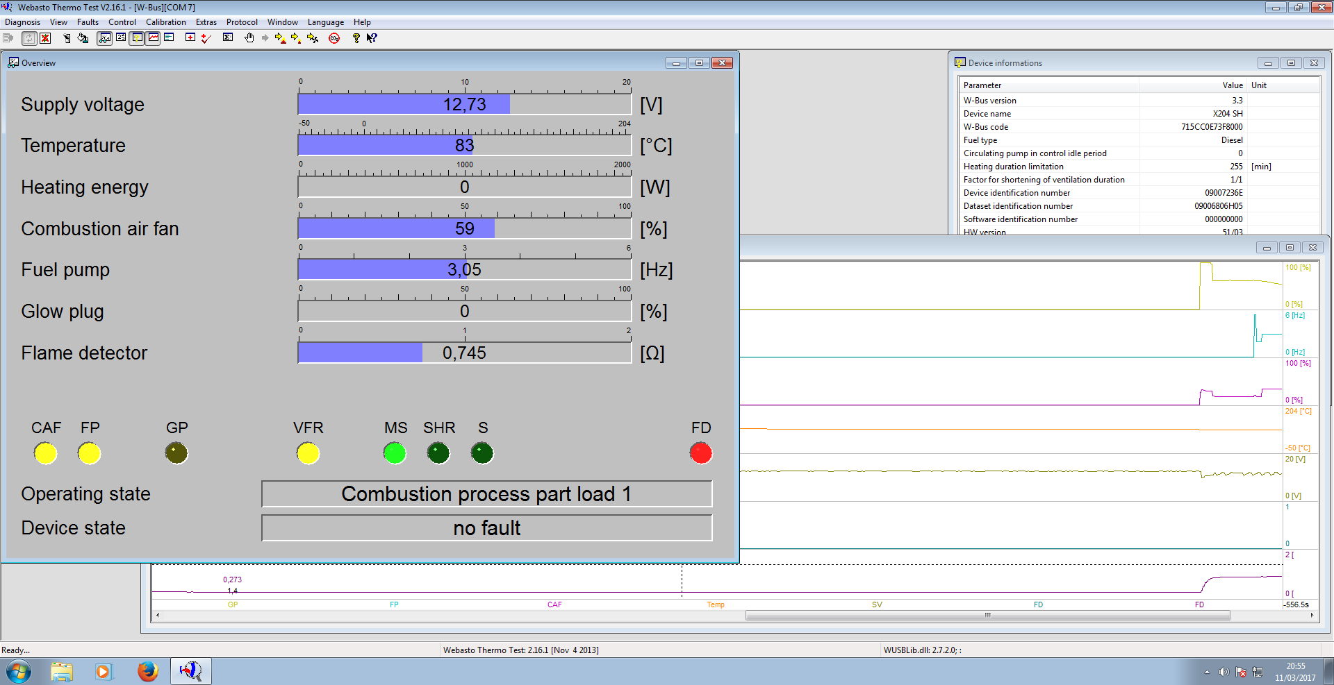
This is a little bit of kit I got to talk to the Webasto TT-V I salvaged from a scrap Jaguar S-Type, and converts USB-RS232 to the standard car diagnostic ODB connector. (These are a much cheaper option at £4 than the official Webasto diagnostic adaptor & loom which is over £90.
PCB Top
There’s really not much to this adaptor, the only signals that are routed to the ODB connector seem to be the +12v on pin 16, K-Line on Pin 7 & L-Line on pin 15. The main IC here is a CH340 USB-Serial interface, with some glue logic in the form of an LM339 quad comparator.
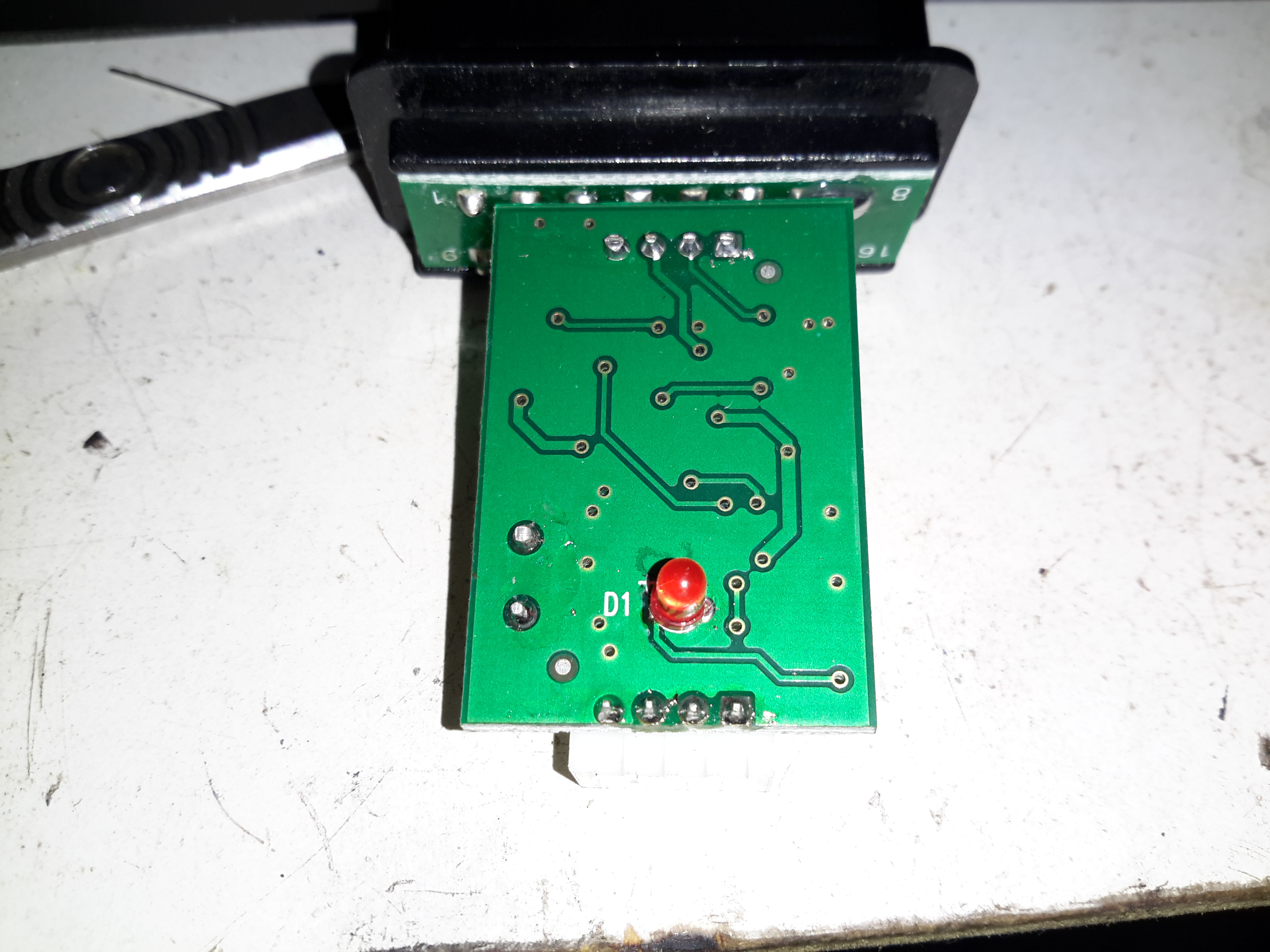
PCB Reverse
The reverse side of the PCB only has the power indicator LED.
As I mentioned in the previous post, these heaters have a standard interface that’s used for control & diagnostics, the W-Bus. This is transmitted over the K-Line of the vehicle bus, and all heaters, regardless of firmware modifications done by the various car manufacturers respond to this interface. Official Webasto diagnostic adaptors are available, but these are just a very expensive serial adaptor. A much cheaper option is a ~£5 Universal ODB adaptor.
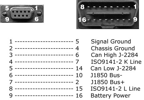
ODB2
Above shows the signals on the ODB connector – the ones we’re interested in here are Pin 16, the +12v supply, and Pin 7, K-Line. Connect Pin 16 to the positive supply to the heater, and Pin 7 to Pin 2 on the Webasto heater. (Valid for all TT-V heaters).
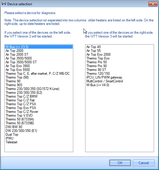
Device Selection
Once these two connections are made to the heater, fire up the Thermo Test software. The screen above will be displayed. Pick W-Bus at top left.
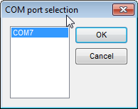
COM Port Selection
First thing, connect the ODB adaptor to USB, and change to the correct COM port in Thermo Test. There may be several in the list, but a newly connected USB device should show up with the highest COM number.
Thermo Test
Once Thermo Test is running, start communications by going to the Diagnosis Menu > Start Diagnostic (F2 keyboard shortcut).
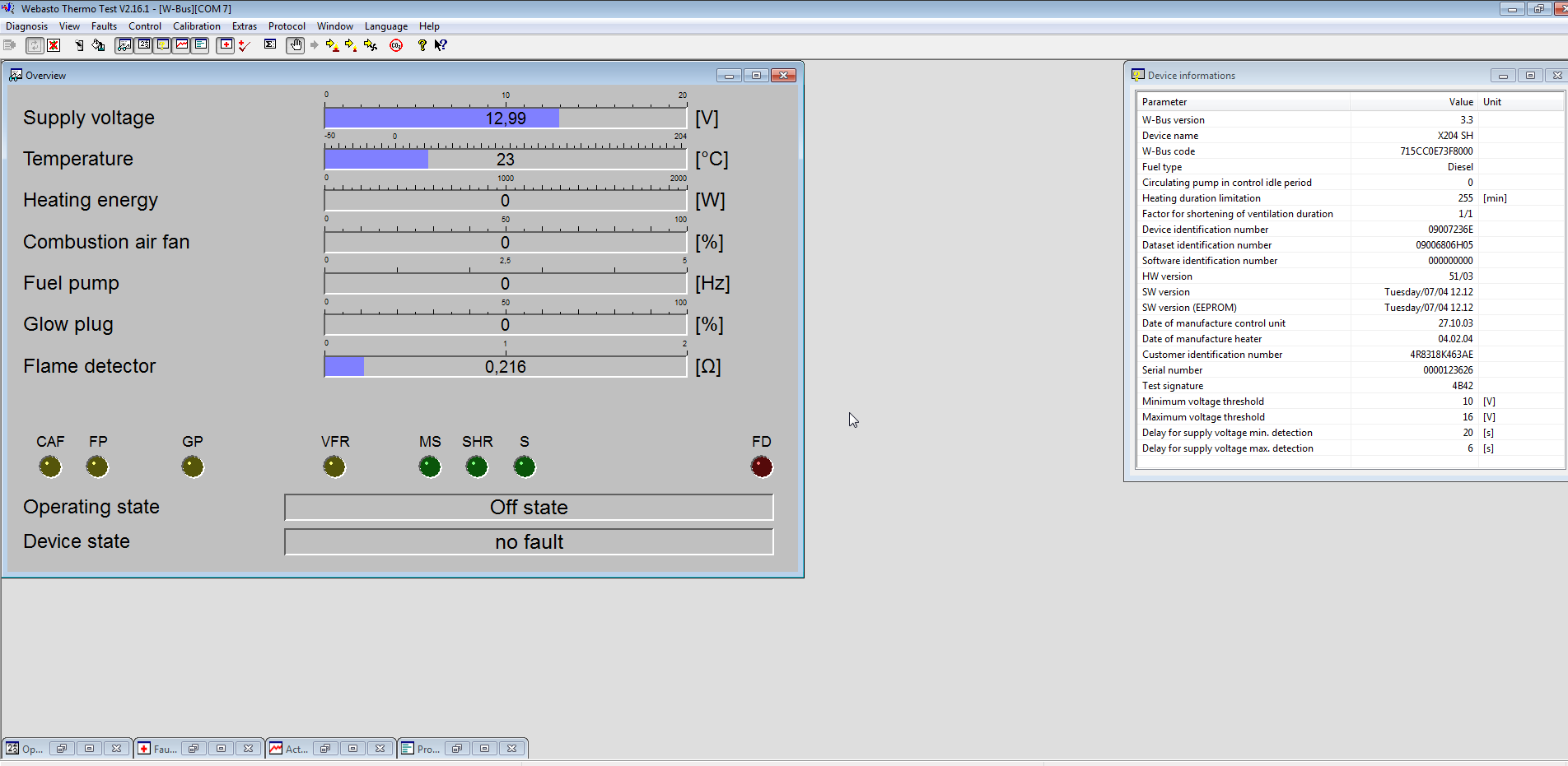
Initialized
After a few seconds, communication will be established. This will show faults, if any are present, and allow testing of the heater & it’s component parts. A summary report can be generated with Diagnosis > View Summary:
Diagnosis report Webasto Thermosystems
------------------------------------------------------------------------------------------
Configuration:
--------------
W-Bus version...............................................................3.3
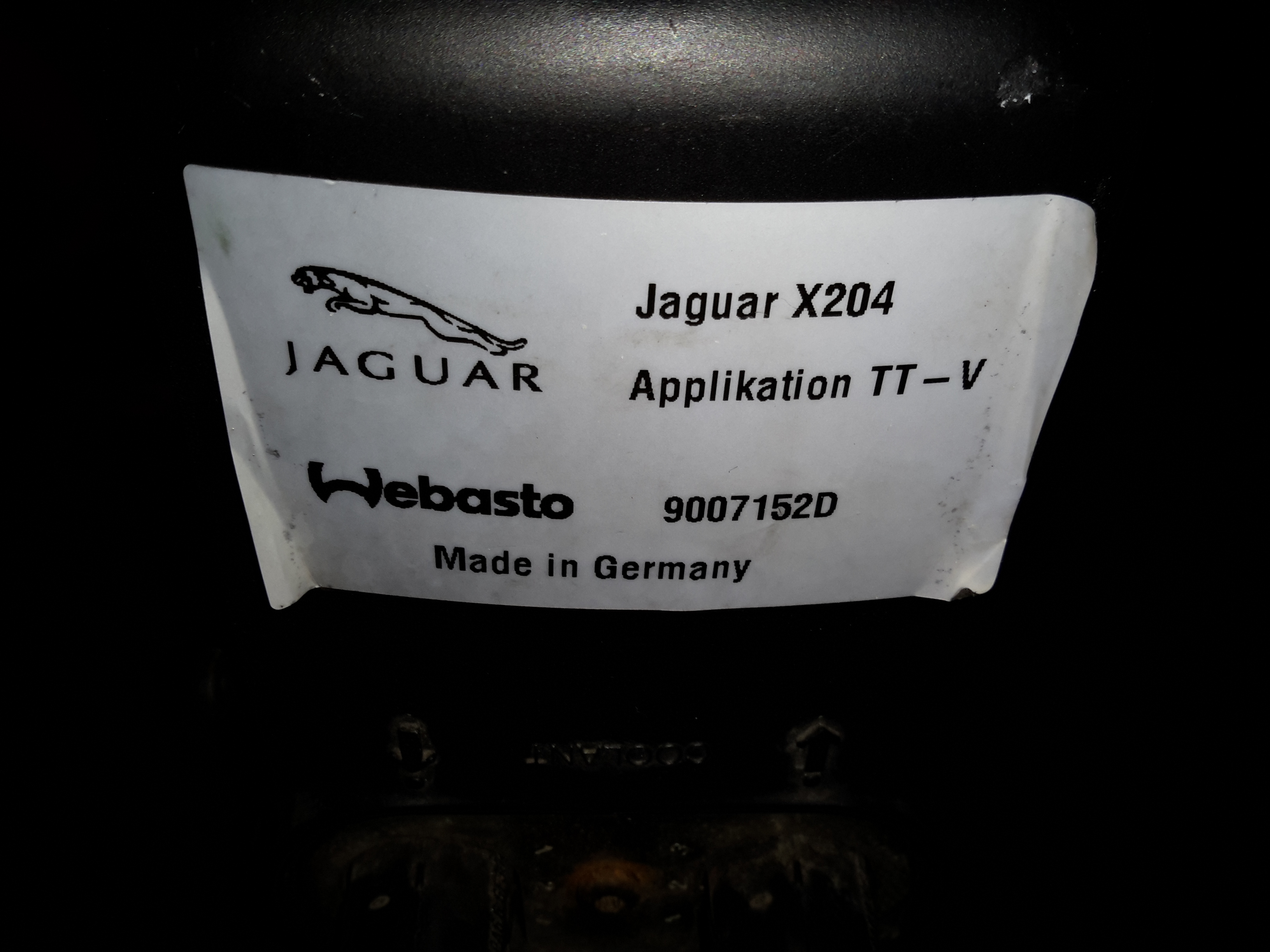
Device name.............................................................X204 SH
W-Bus code.......................................................715CC0E73F8000
Fuel type................................................................Diesel
Circulating pump in control idle period.......................................0
Heating duration limitation.................................................255 [min]
Factor for shortening of ventilation duration...............................1/1
Device identification number..........................................09007236E
Dataset identification number.......................................09006806H05
Software identification number........................................000000000
HW version................................................................51/03
SW version..................................................Tuesday/07/04 12.12
SW version (EEPROM).........................................Tuesday/07/04 12.12
Date of manufacture control unit.......................................27.10.03
Date of manufacture heater.............................................04.02.04
Customer identification number.....................................4R8318K463AE
Serial number........................................................0000123626
Test signature.............................................................4B42
Minimum voltage threshold....................................................10 [V]
Maximum voltage threshold....................................................16 [V]
Delay for supply voltage min. detection......................................20 [s]
Delay for supply voltage max. detection.......................................6 [s]
Operating data:
---------------
Working hours.............................................................44:03 [h:m]
Operating hours.........................................................5388:08 [h:m]
Start count...............................................................19129
Burning duration PH 1..33%.................................................0:00 [h:m]
Burning duration PH 34..66%................................................0:00 [h:m]
Burning duration PH 67..100%...............................................0:00 [h:m]
Burning duration PH >100%..................................................0:00 [h:m]
Burning duration SH 1..33%.................................................0:00 [h:m]
Burning duration SH 34..66%................................................0:00 [h:m]
Burning duration SH 67..100%...............................................0:00 [h:m]
Burning duration SH >100%..................................................0:00 [h:m]
Working duration PH........................................................0:51 [h:m]
Working duration SH......................................................121:10 [h:m]
Start counter PH..............................................................6
Start counter SH............................................................854
Ventilation duration.......................................................0:00 [h:m]
Error:
------
------------------------------------------------------------------------------------------
12.03.17 17:17:30 Webasto Thermo Test 2.16.1
This shows all the important stuff, including running hours. (5388Hrs on this heater!). Most importantly, there are no faults listed.
Heater Running
The heater can be fully tested by issuing a start command from the Command Menu > Parking Heating option. Obviously cooling water will be required for this, along with an external water pump. (The water pump control output on these heaters seems to be totally disabled in firmware, as they rely on the engine’s coolant pump). I used a bucket of water along with a small centrifugal pump to provide the cooling. During this test I noted that the firmware is much more aggressive in these units. The marine versions shut down at ~72°C water temperature, whereas these don’t so the same until ~90°C.
Now I’ve managed to communicate with the heater, I’ll get onto building a standalone controller so I can dispense with the Windows VM for control.
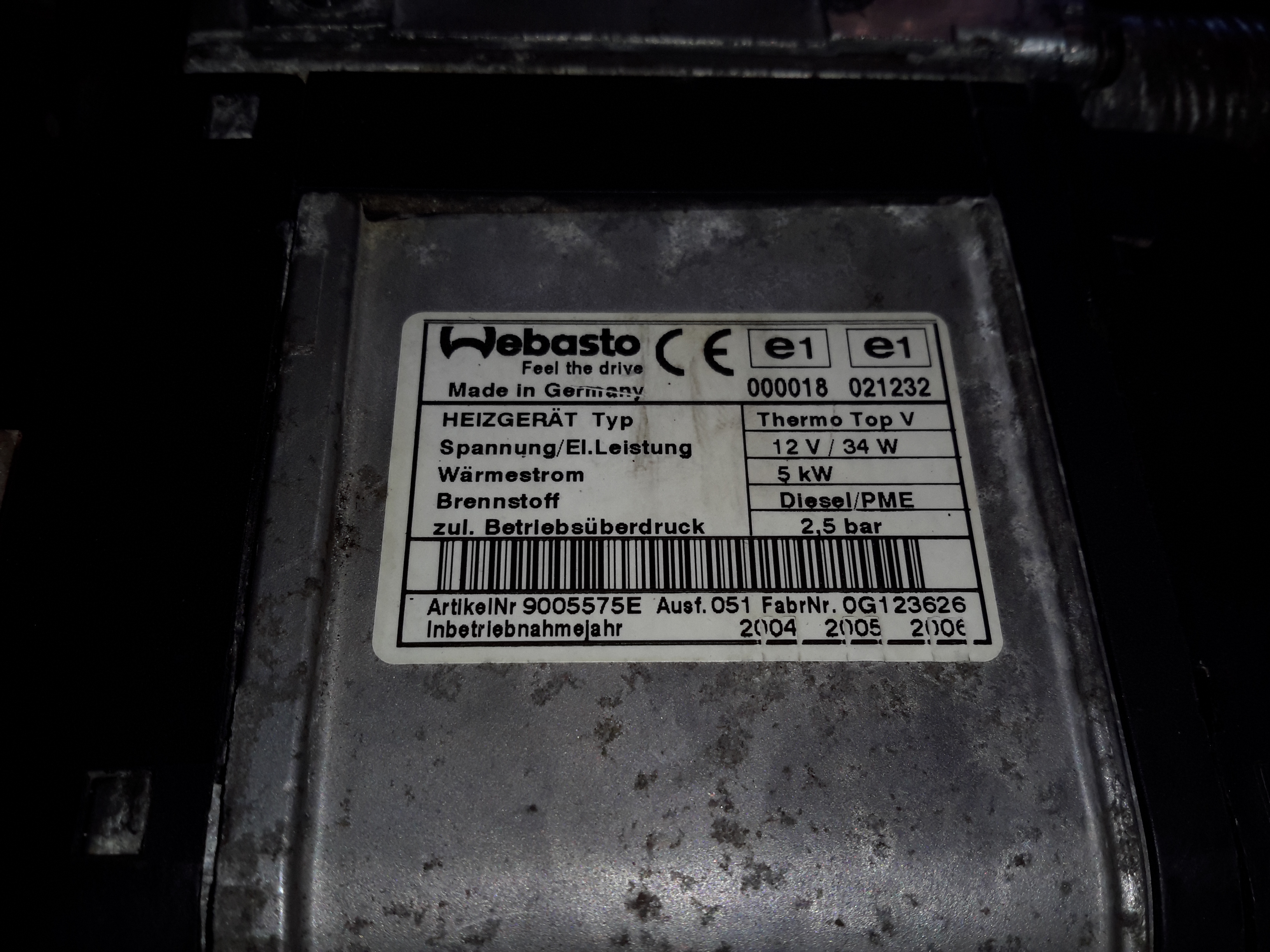
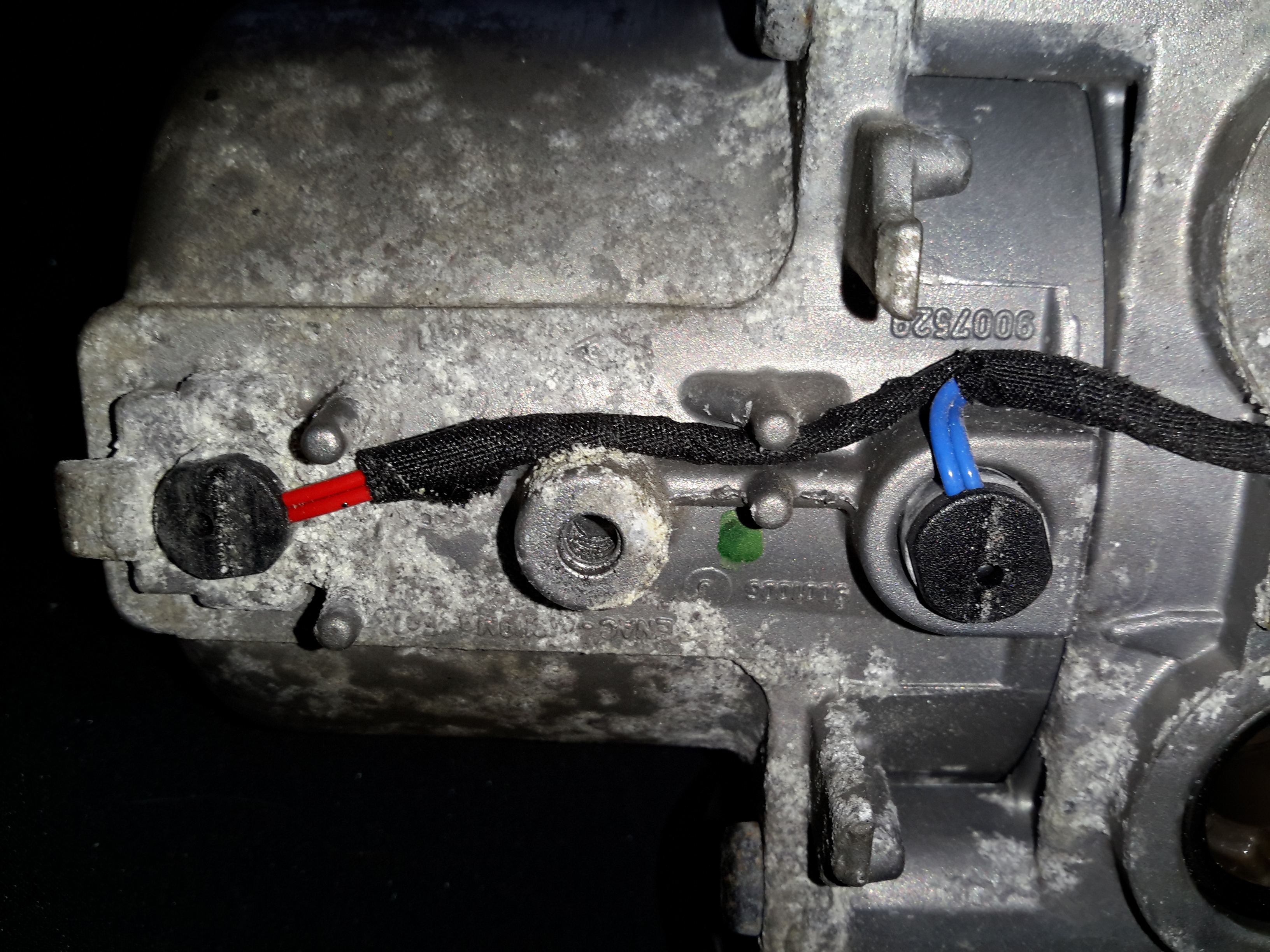
Here’s another Diesel-fired heater related project – these Webasto heaters are fitted to Jaguar S-Type cars as auxiliary heaters, since (according to the Jag manual), the modern fuel-efficient diesels produce so little waste heat that extra help is required to run the car’s climate control system. (Although this seems to nullify any fuel efficiency boost, as the fuel saved by not producing so much waste heat in the engine itself is burned in an aux heater to provide heat anyway). The unfortunate part is these units don’t respond to applying +12v to Pin 1 of the ECU to get them to start – they are programmed to respond to CAN Bus & K-Line Bus only, so they require a bit more effort to get going. They also don’t have a built-in water circulation pump unlike the Webasto Thermo Top C heaters – they expect the water flow to be taken care of by the engine’s coolant pump.
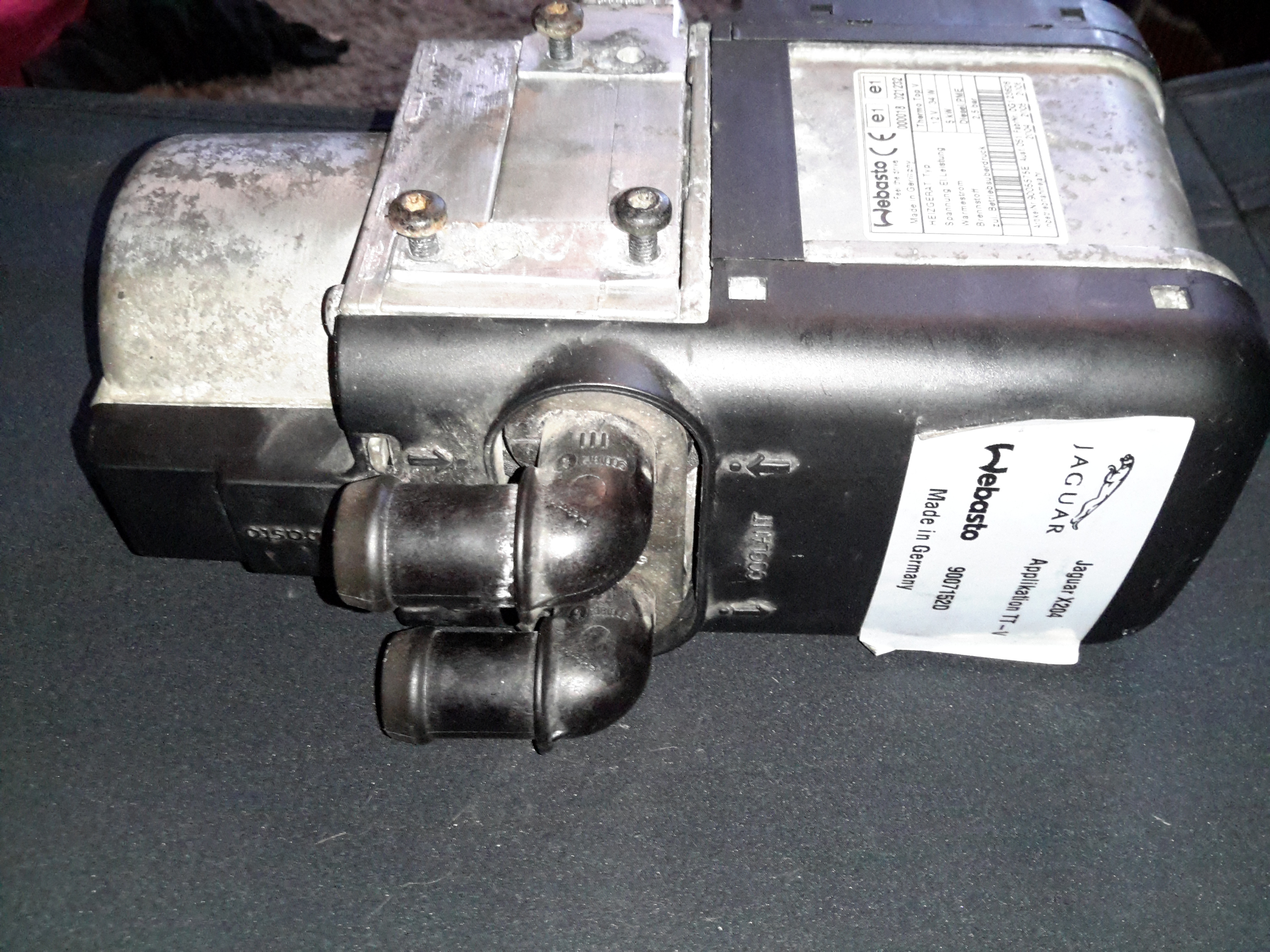
Webasto LabelWater Side
The water ports are on the side of this heater instead of the end, the heat exhanger is on the left. These hearers are fitted to the car under the left front wing, behind a splash guard. Pretty easy to get to but they get exposed to all the road dirt, water & salt so corrosion is a little problem. The fuel dosing pump is in a much more difficult spot to get at – it’s under the car next to the fuel tank on the right hand side. Access to the underside with stands is required to get at this.
ECU Side
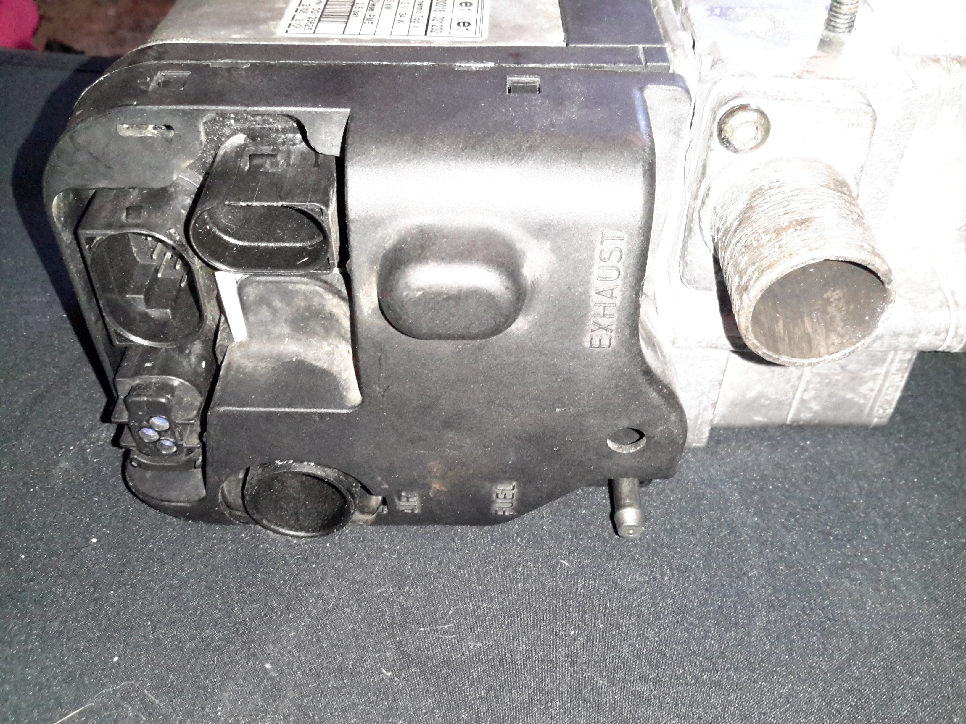
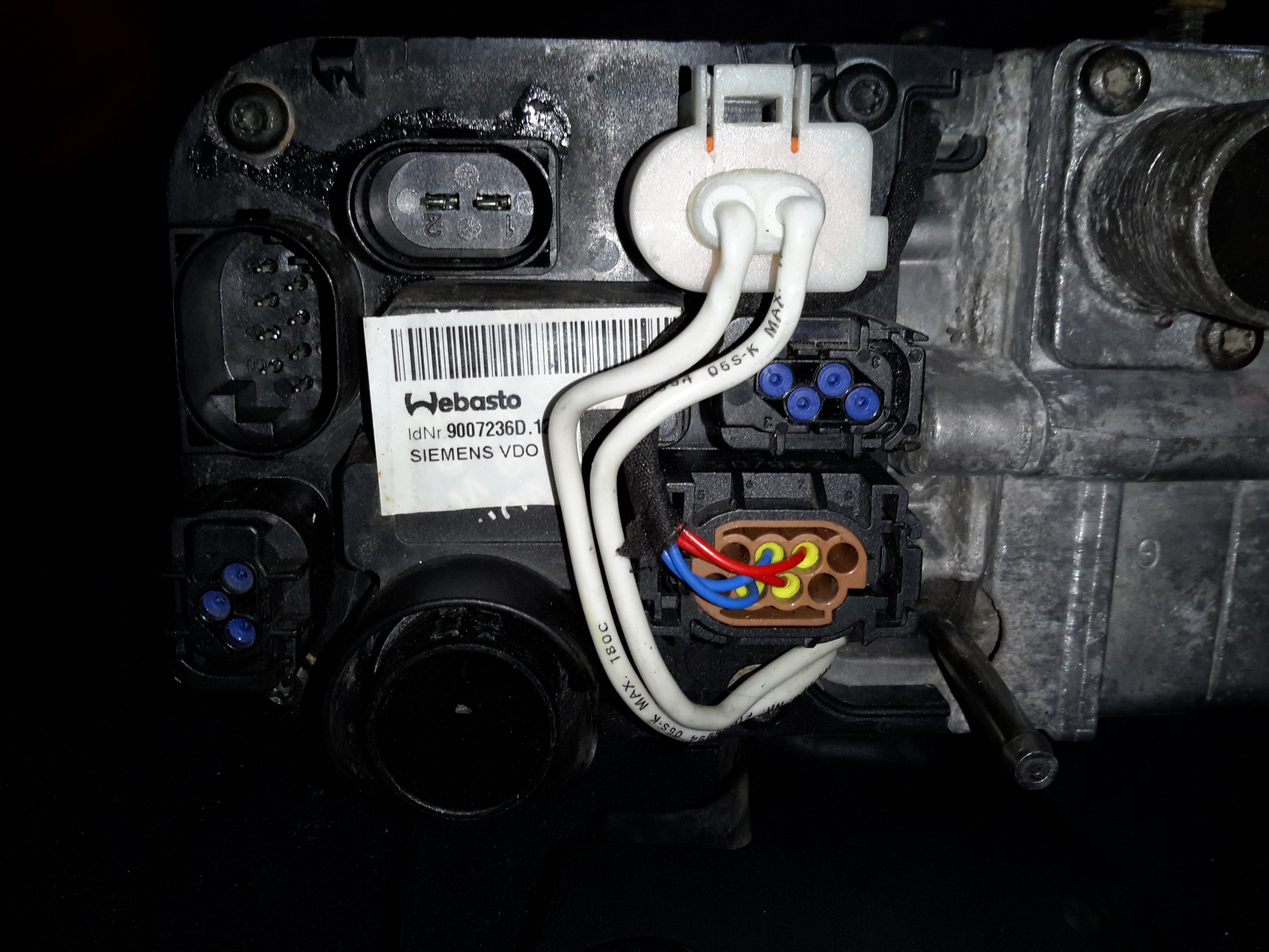
The ECU side has all the other connections – Combustion air, exhaust, fuel, power & control.
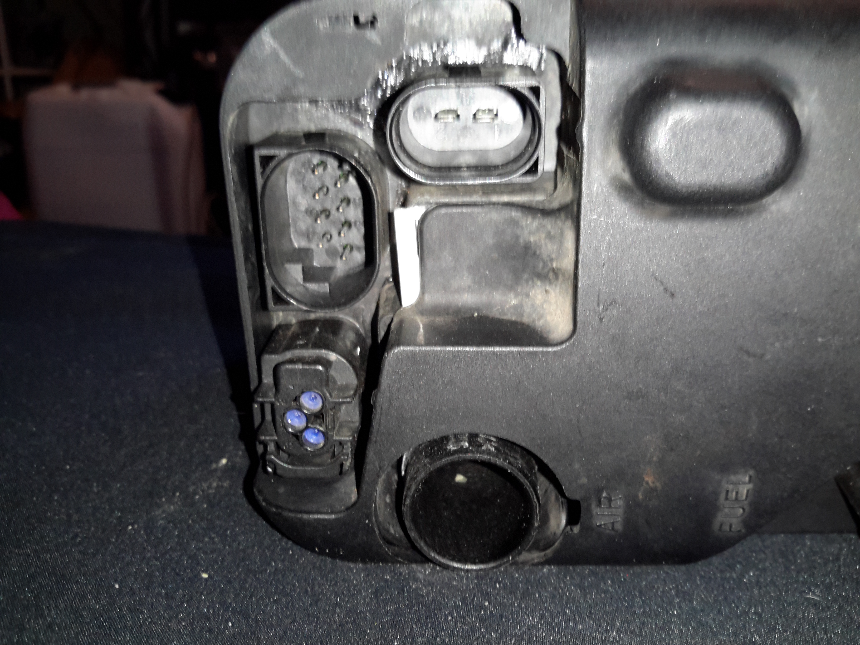
External Connectors
Only two of the external connectors are used on these heaters, the large two pin one is for main power – heavy cable required here as the current draw can climb to ~30A on startup while the glow plug fires. The 8-pin connector on the left is the control connector, where the CAN / K-Line / W-Bus buses live. The fuel dosing pump is also supplied from a pin on this connector. The small 3-pin under that is a blank for a circulation pump where fitted. Pinouts are here:
Pin
Signal
1
Battery Positive
2
Battery Negative
Pin Number
Signal
Notes
1
Telestart / Heater Enable
Would usually start the heater with a simple +12v ON signal, but is disabled in these heaters.
2
W-Bus / K-Line
Diagnostic Serial Bus Or Webasto Type 1533 Programmer / Clock
3
External Temp Sensor
4
CAN-
CAN Bus Low
5
Fuel Dosing Pump
Fuel Pump output. Connect pump to this pin & ground. Polarity unimportant.
6
Solenoid Valve
Fuel cutoff solenoid optionally fitted here.
7
CAN+
CAN Bus High
8
Cabin Heater Fan Control
This output switches on when heater reaches +50°C to control car heater blower
Pin
Signal
Notes
1
?
?
2
Circulation Pump +
3
Circulation Pump -
ECU Cover Removed
Removing the clipped-on plastic cover reveals the other ECU connectors. The large white one feeds the glow plug, & the large multi-pin below brings in the temp & overheat sensor signals.
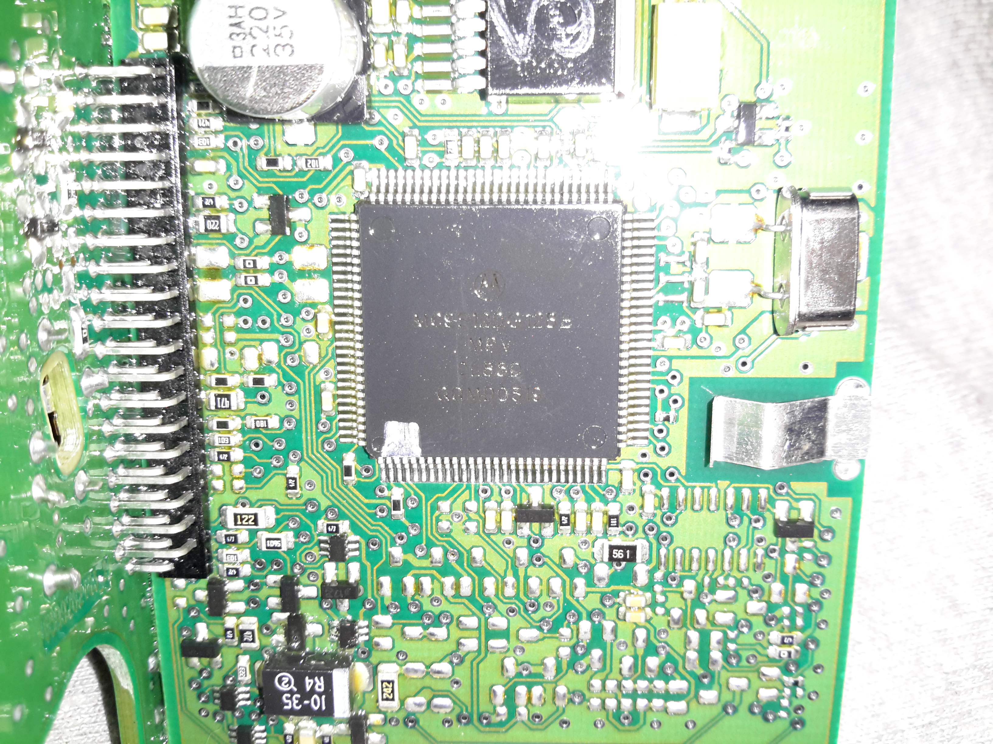
MC9S12DT128B Microcontroller
The heart of the ECU is a massive microcontroller, a Freescale MC9S12DT128B, attached to a daughterboard hooked into the ECU power board.
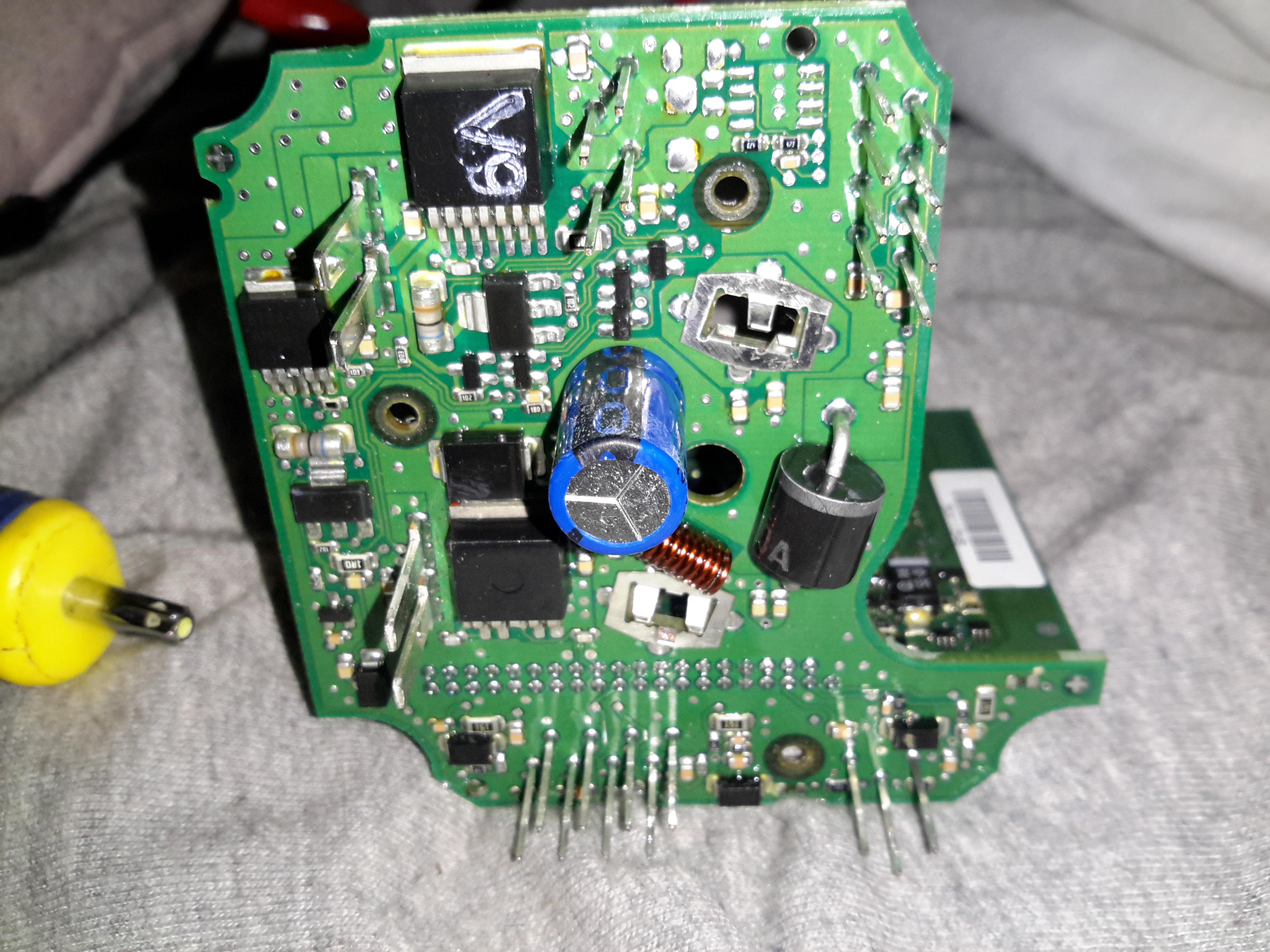
Power Section
The high power section is on the board just under the connectors, here all the large semiconductors live for switching the fan motor, glow plug, external loads, etc.
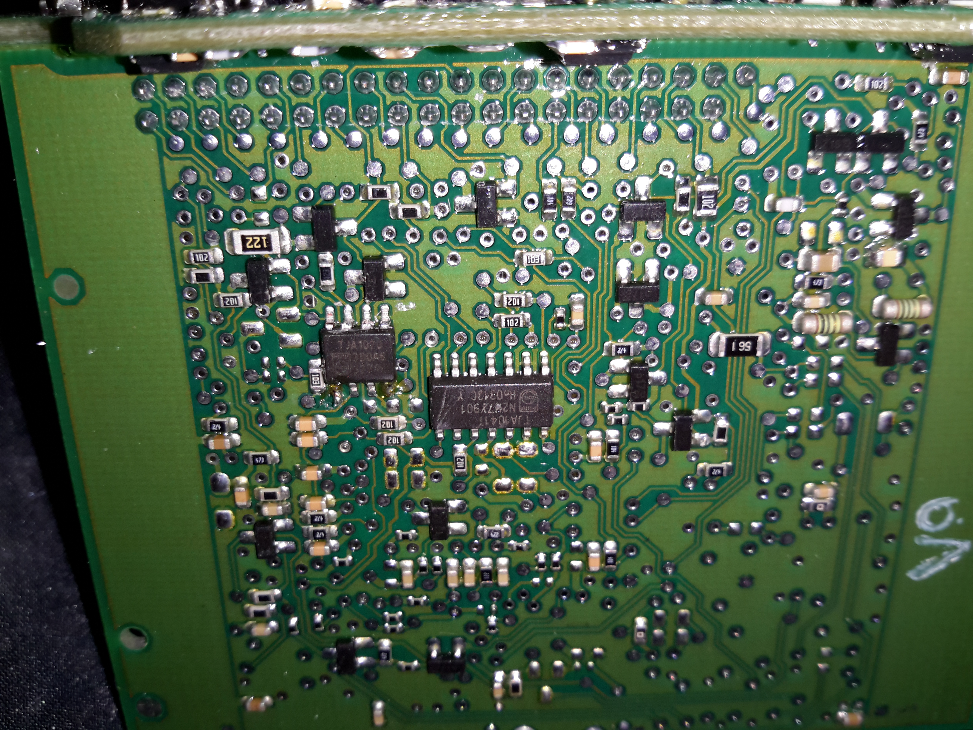
LIN & CAN Bus Transceivers
The bus transceivers are separate ICs on the control board, a TJA1041 takes care of the CAN bus. There’s also a TJA1020 LIN bus transceiver here, which is confusing since none of the Webasto documentation mentions LIN bus control.
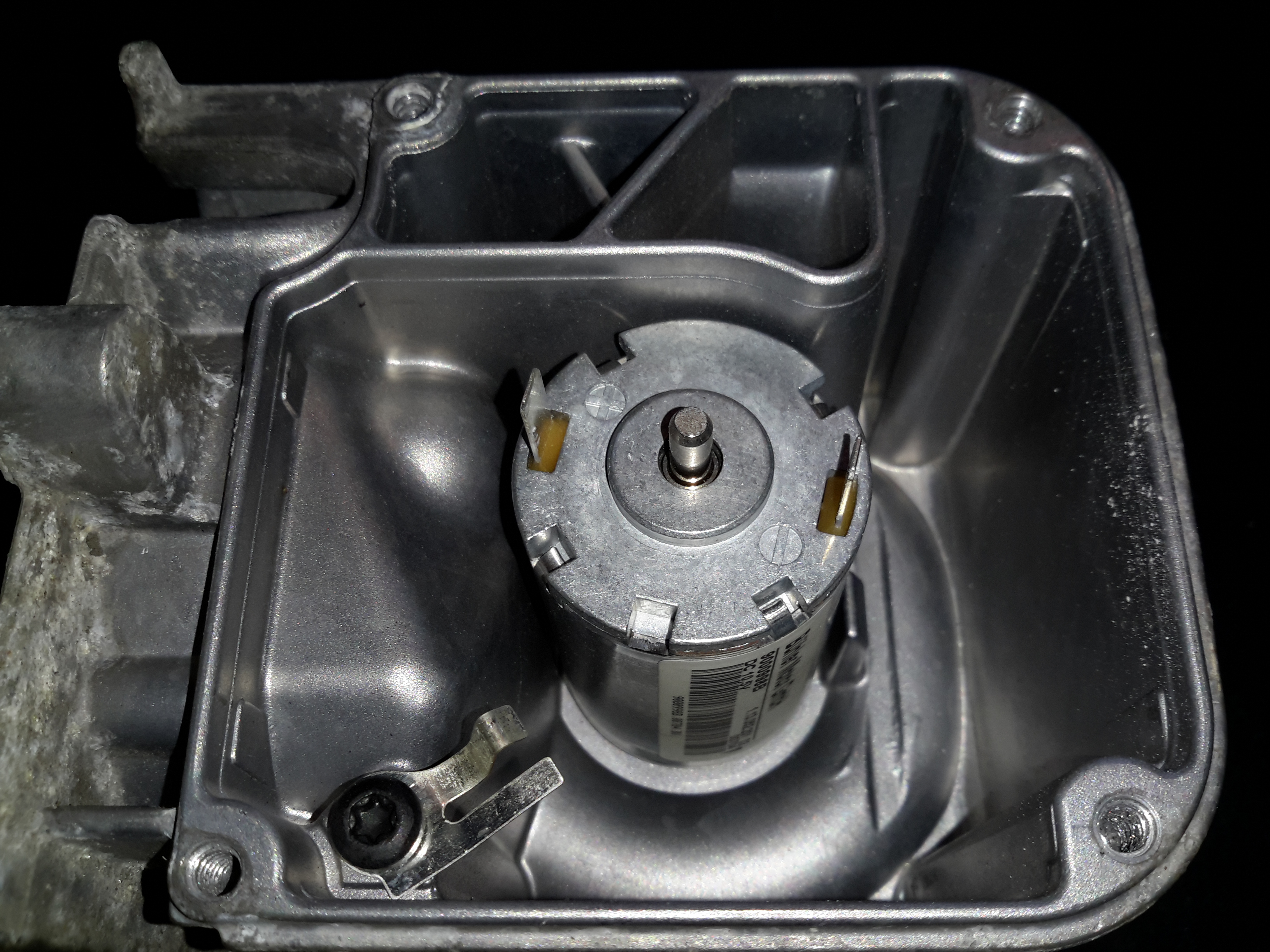
Combustion Fan Motor
The combustion fan motor is in the ECU compartment, nicely sealed away from the elements. There is no speed sensor on these blowers, unlike the Eberspacher ones.
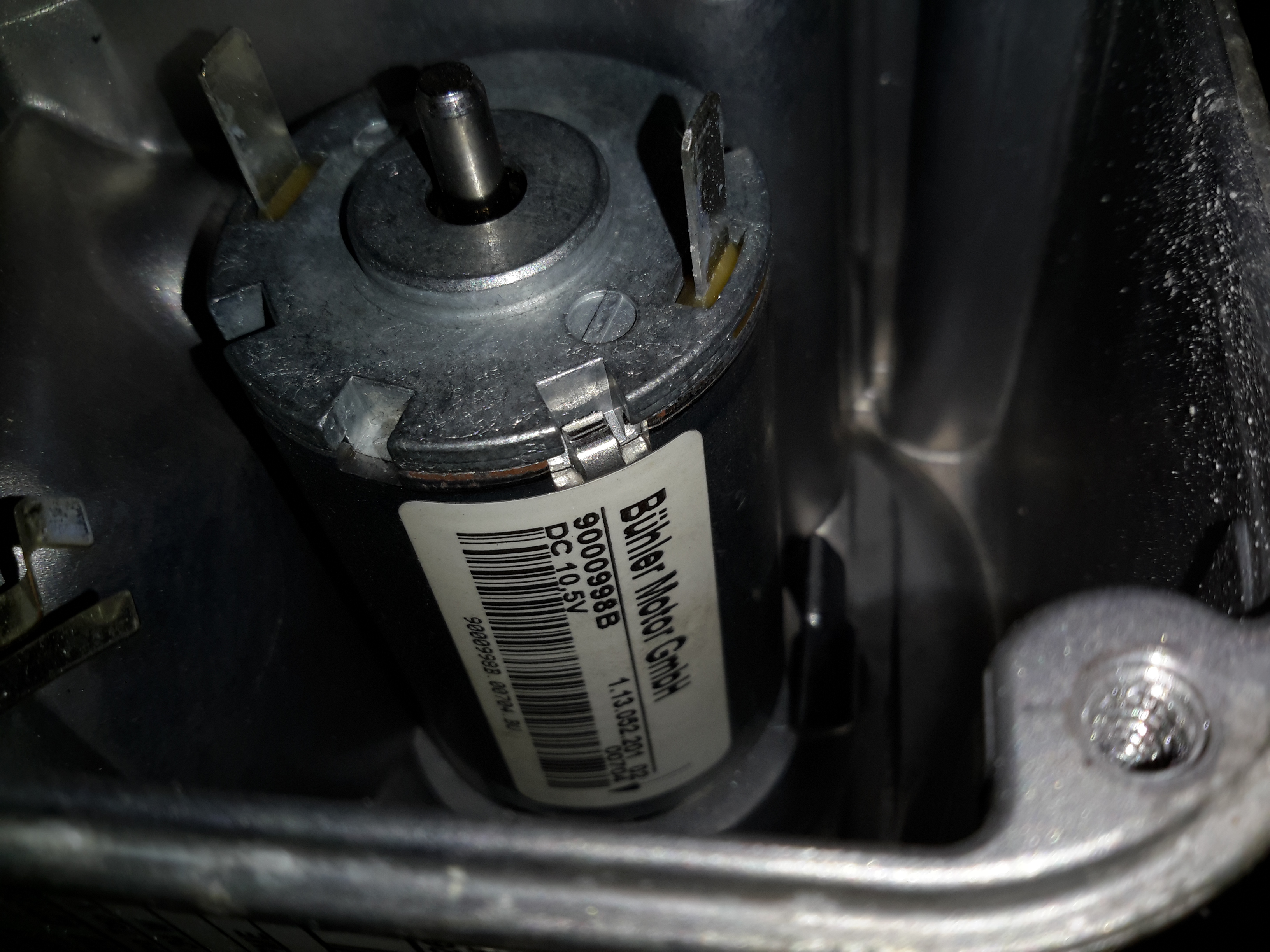
Motor Details
The motor is a Buhler, rated at 10.5v.
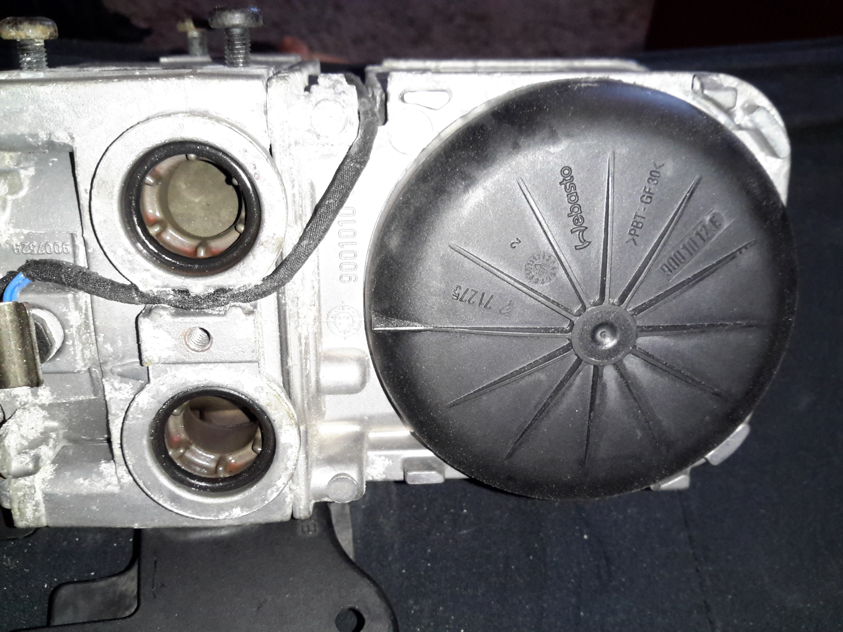
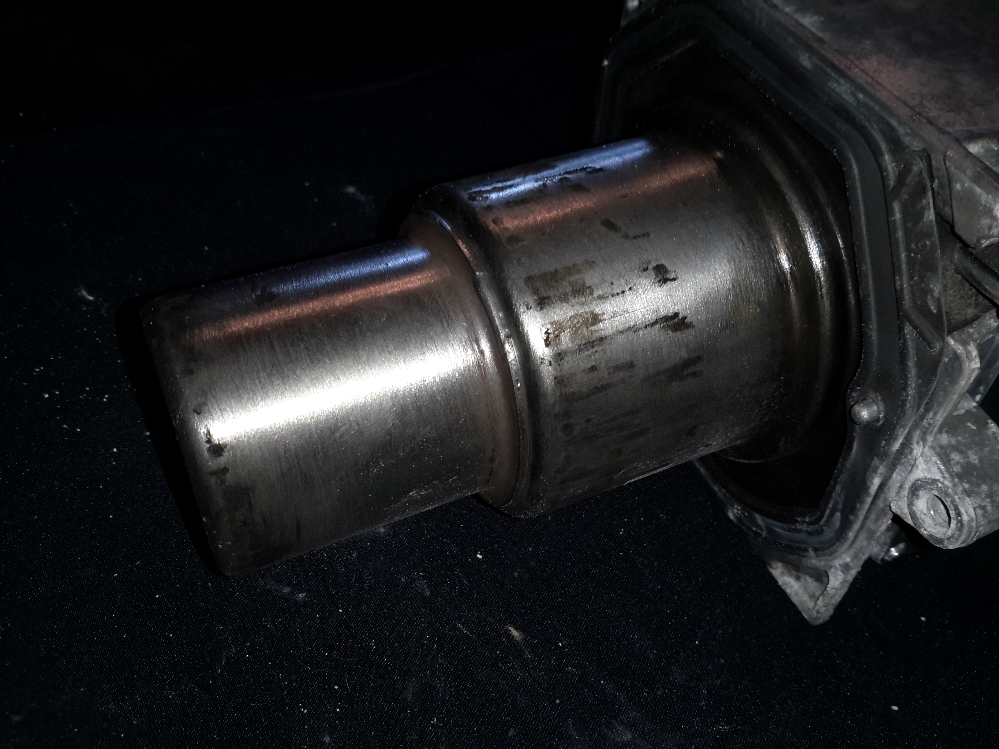
Water Ports & Combustion Fan Cover
Unclipping the cover from the other end reveals the combustion fan, it’s under the black cover. (These are side-channel blowers, to provide the relatively high static pressure required to run the burner).
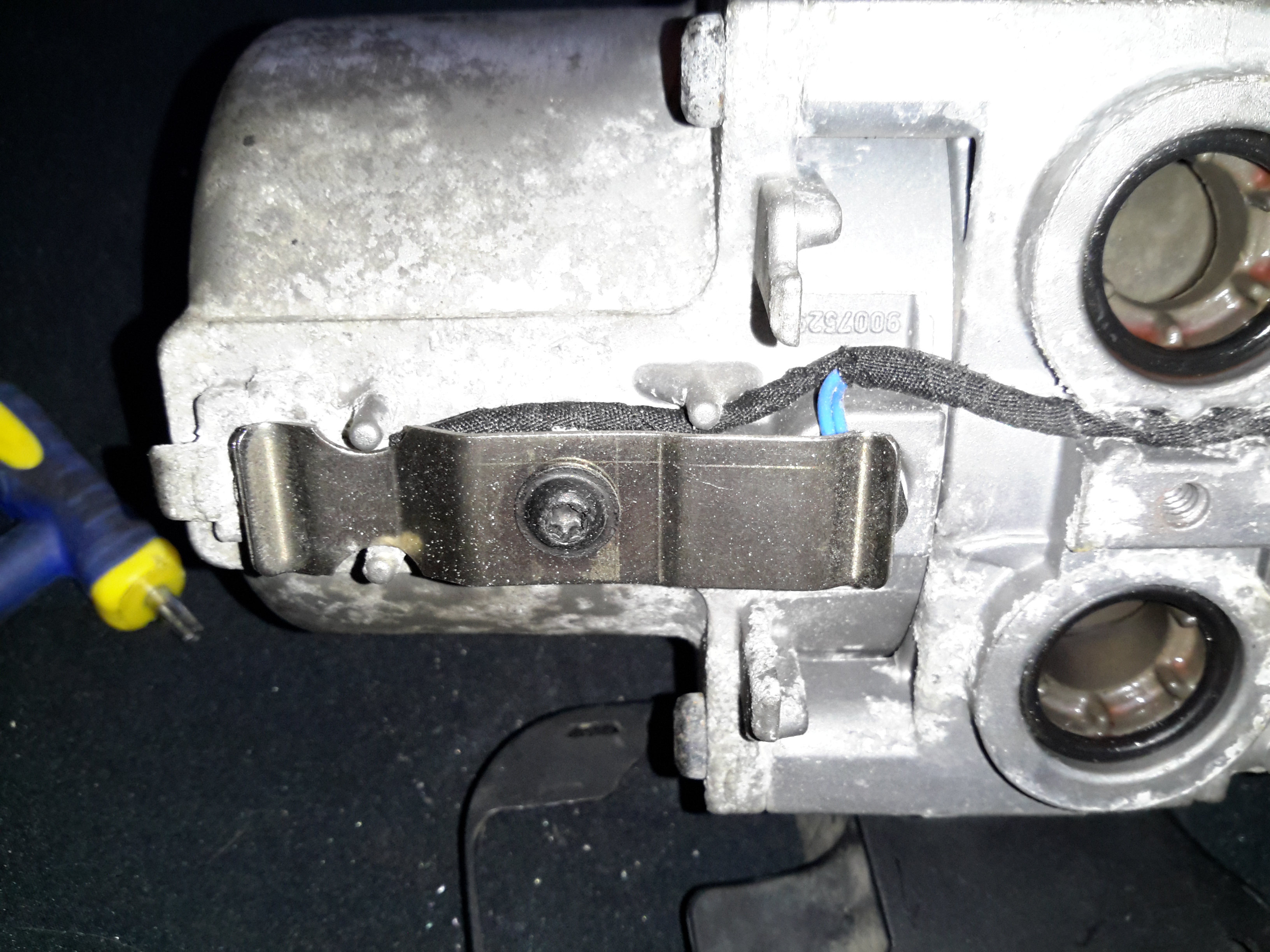
Sensor Clip
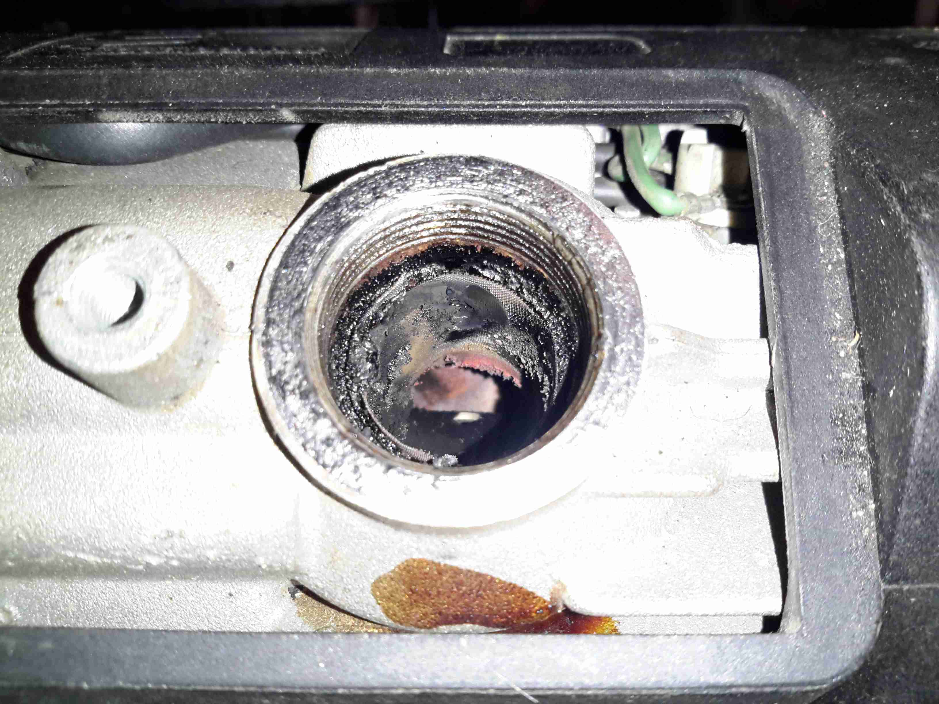
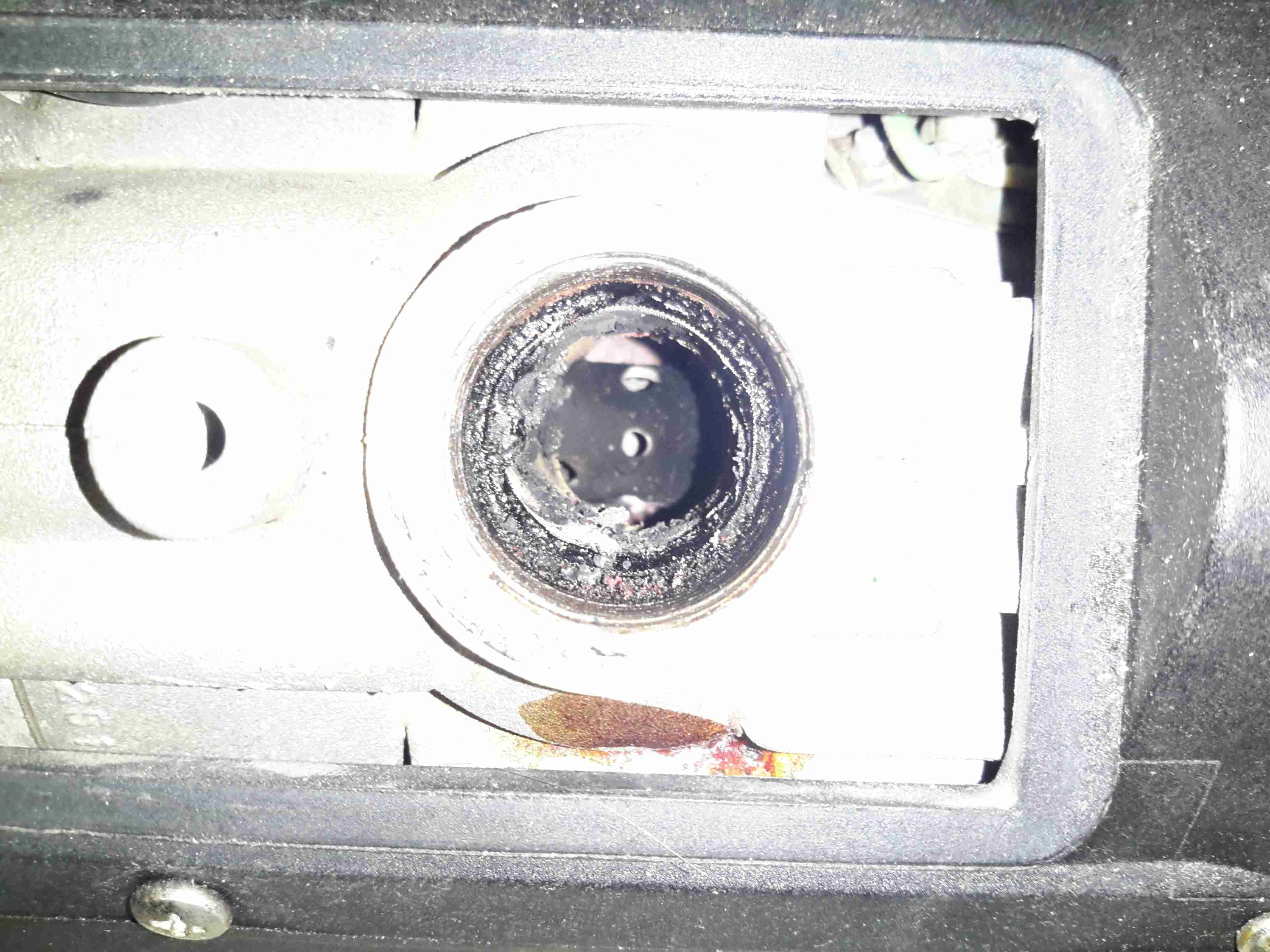
The overheat & temperature sensors are on the end of the heat exchanger, retained by a stainless clip.
Temp & Overheat Sensors
With the clip removed, the sensors can be seen better. There’s some pretty bad corrosion of the aluminium alloy on the end sensor, it’s seized in place.
Burner
The heater splits in half to reveal the evaporative burner itself. I’ve already cleaned the black crud off with a wire brush here, doesn’t look like this heater has seen much use as it’s pretty clean inside.
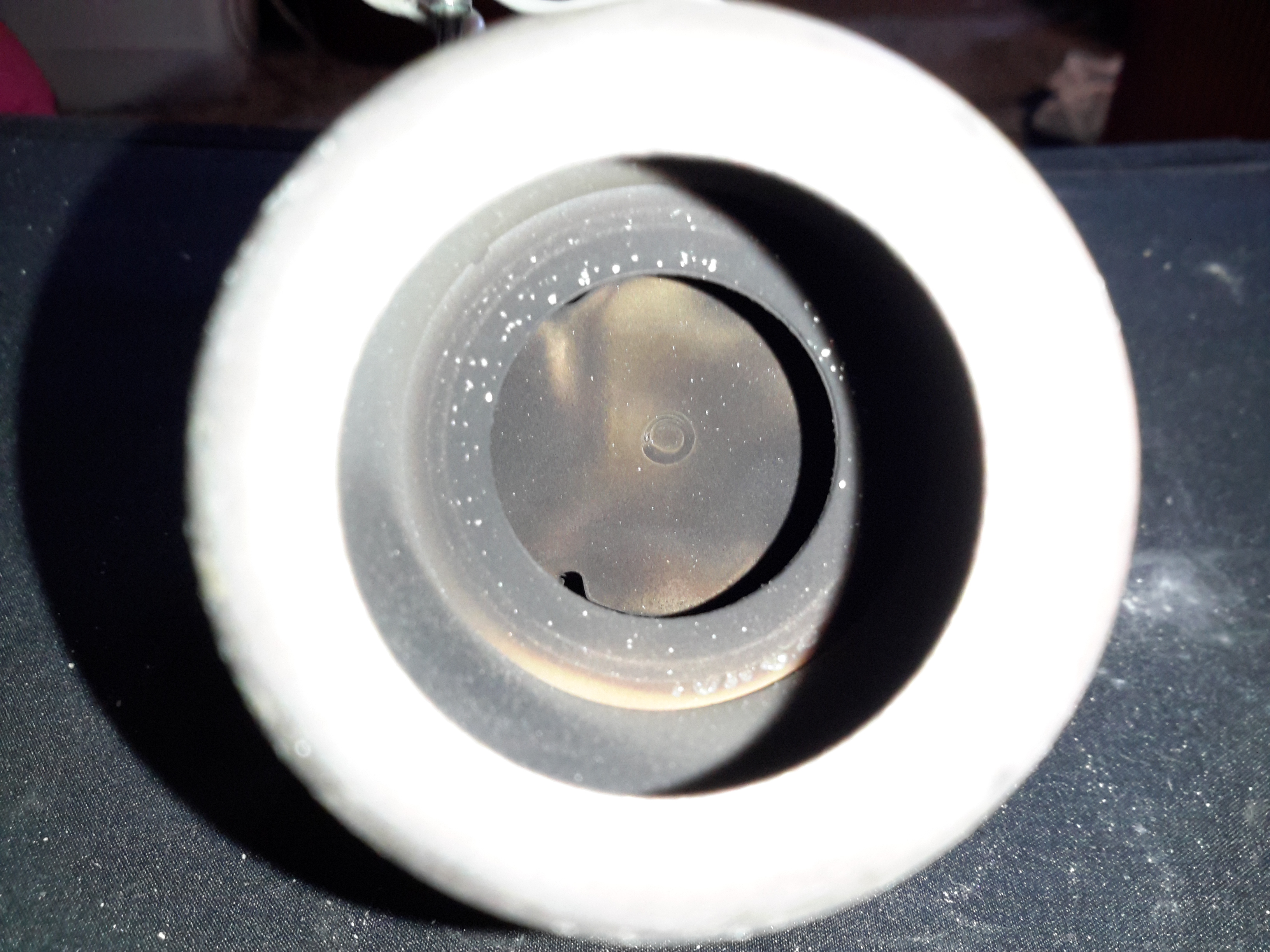
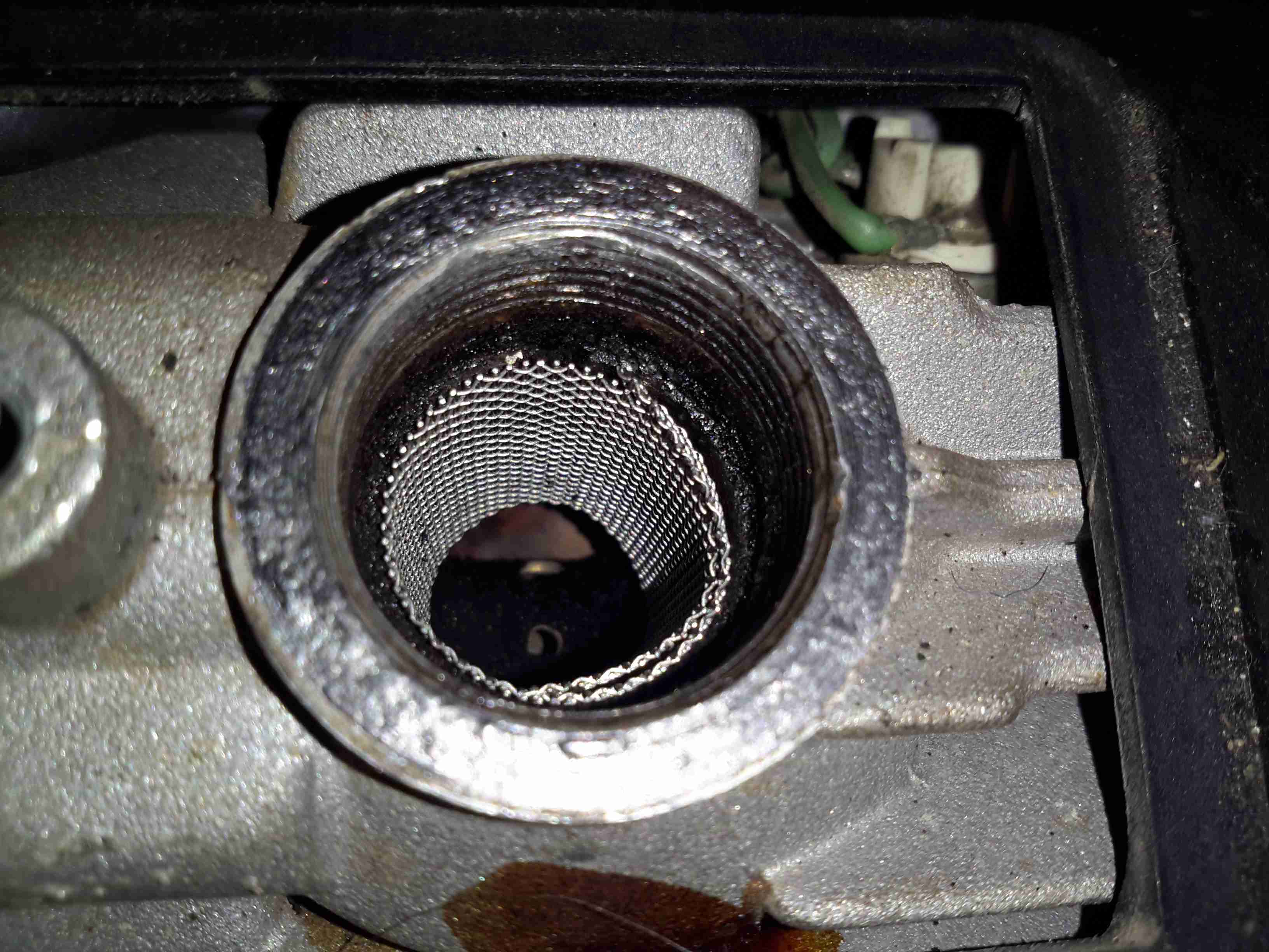
Burner Chamber
Inside the burner the fuel evaporates & is ignited. There is a brass mesh behind the backplate of the burner to assist with vaporisation.
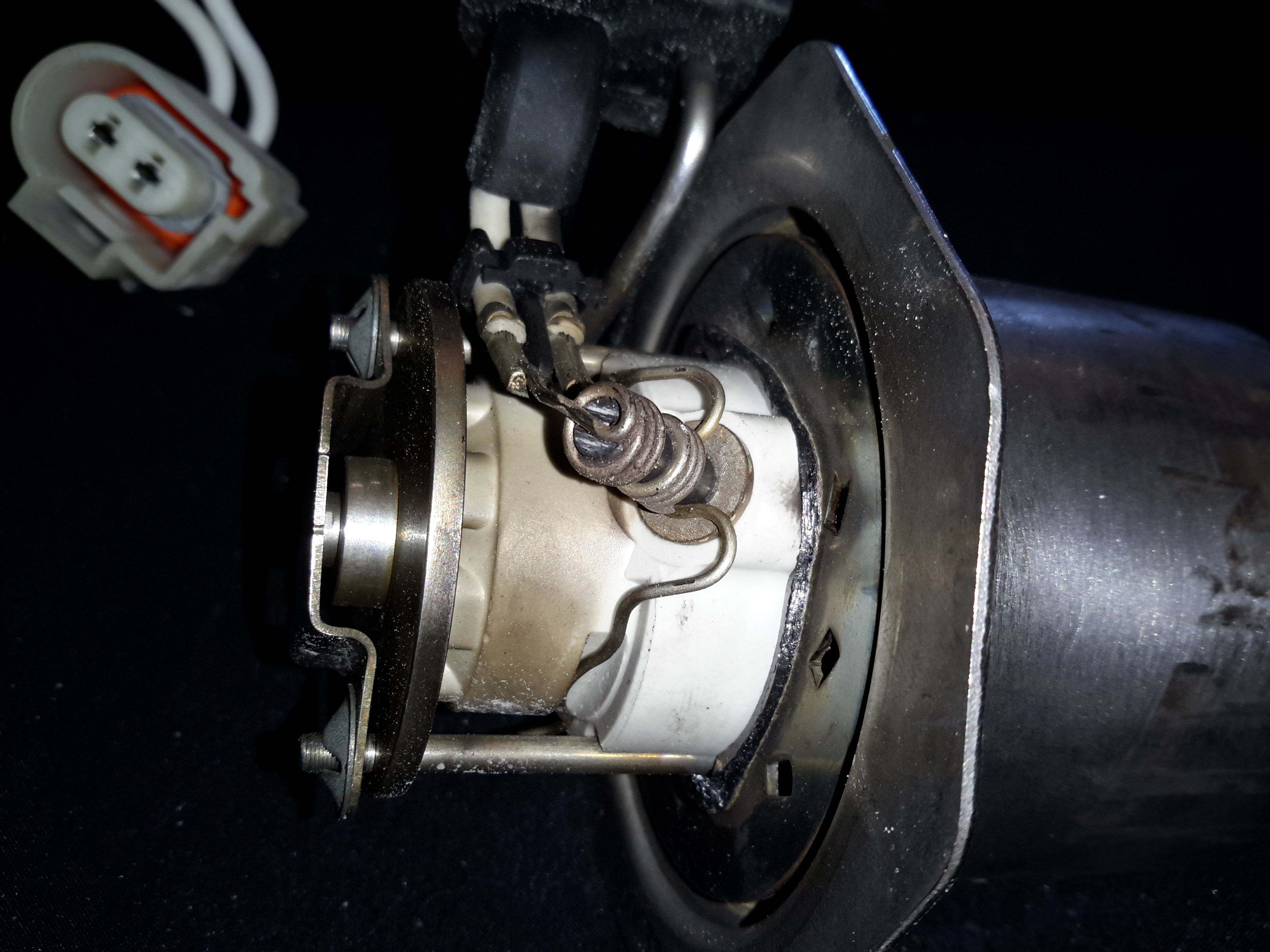
Glow Plug
The glow plug is fitted into the side of the burner ceramic here. This is probably a Silicon Carbide device. It also acts as a flame sensor when the heater has fired up. The fuel inlet line is to the left under the clamp.
Heat Exhanger
The hot gases from the burner flow into the heat exchanger here, with many fins to increase the surface area. There’s only a couple of mm coating of carbon here, after 10 years on the car I would have expected it to be much more clogged.
I’m currently waiting on some components to build an interface so I can get the Webasto Thermo Test software to talk to the heater. Once this is done I can see if there are any faults logged that need sorting before I can get this heater running, but from the current state it seems to be pretty good visually. More to come once parts arrive!
The full service manual for these heaters can be grabbed from here, along with the wiring details for the Jaguar implementation & the Thermo Test software for talking to them:
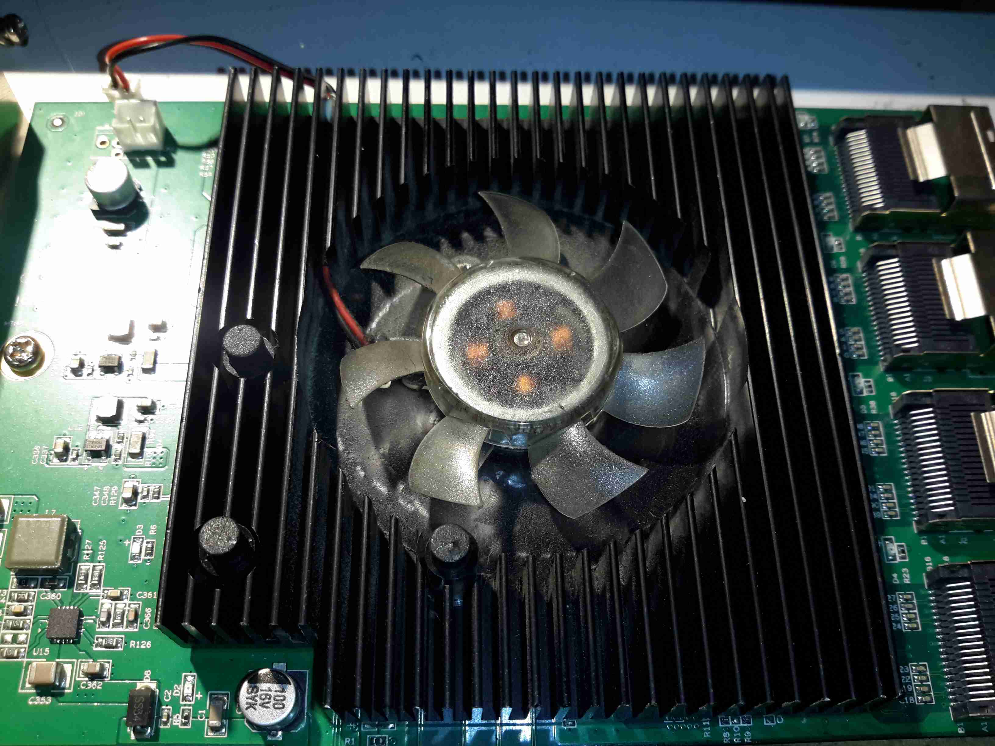
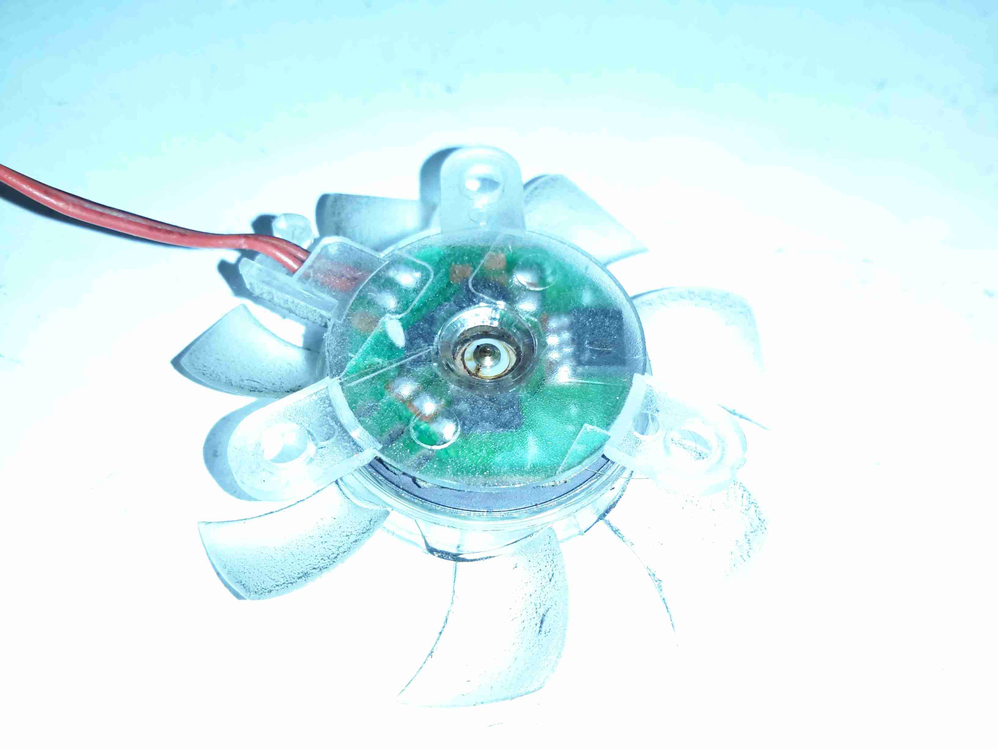
It’s been 4 months since I did a rejig of my storage server, installing a new 16-port SATA HBA to support the disk drives. I mentioned the factory fan the card came with in my previous post, and I didn’t have many hopes of it surviving long.
Heatsink
The heatsink card has barely had enough time to accumulate any grime from the air & the fan has already failed!
There’s no temperature sensing or fan speed sensing on this card, so a failure here could go unnoticed, and under load without a fan the heatsink becomes hot enough to cause burns. (There are a total of 5 large ICs underneath it). This would probably cause the HBA to overheat & fail rather quickly, especially when under a high I/O load, with no warning. In my case, the bearings in the fan failed, so the familiar noise of a knackered sleeve bearing fan alerted me to problems.
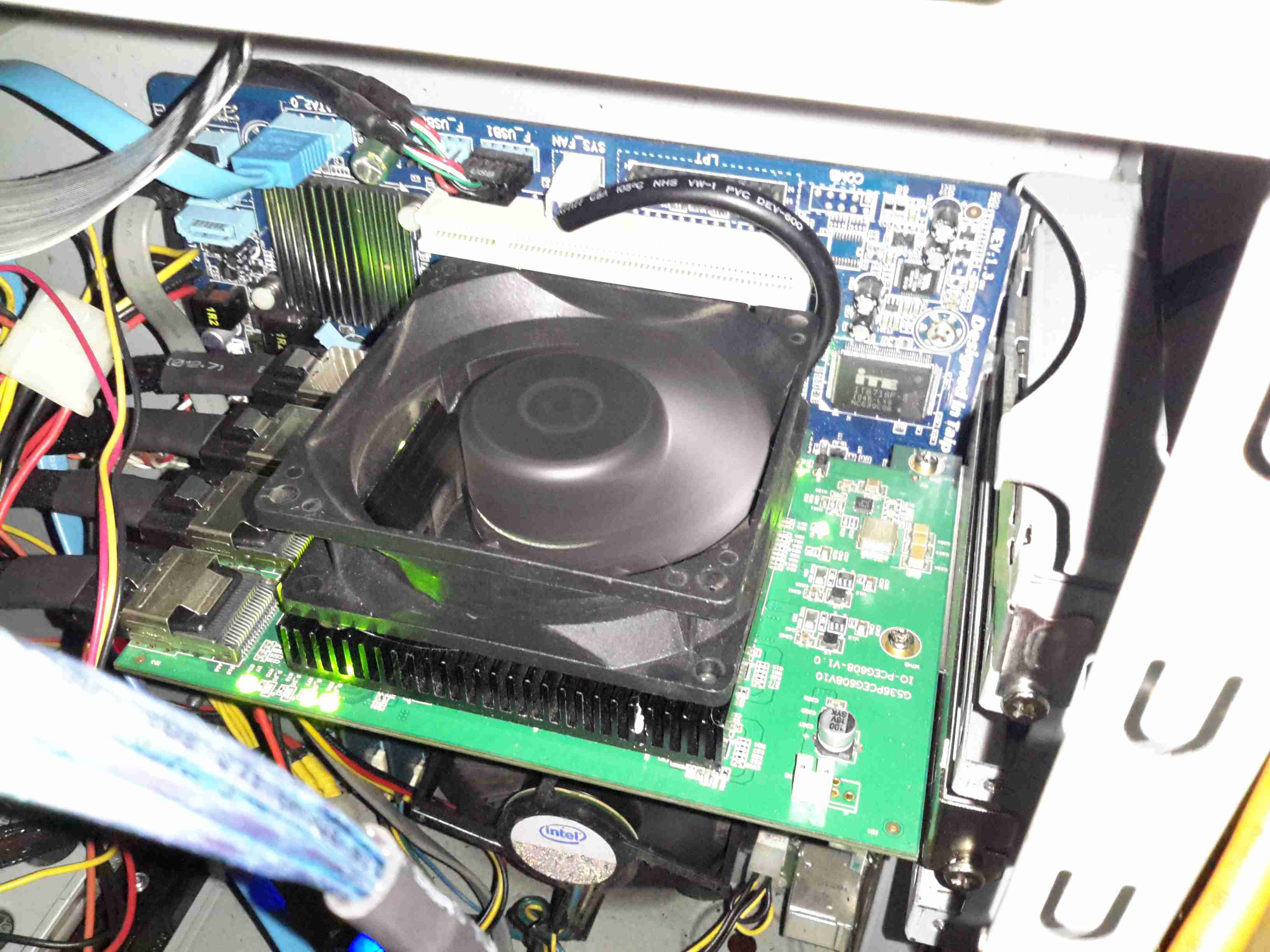
Replacement Fan
A replacement 80mm Delta fan has been attached to the heatsink in place of the dead fan, and this is plugged into a motherboard fan header, allowing sensing of the fan speed. The much greater airflow over the heatsink has dramatically reduced running temperatures. The original fan probably had it’s bearings cooked by the heat from the card as it’s airflow capability was minimal.
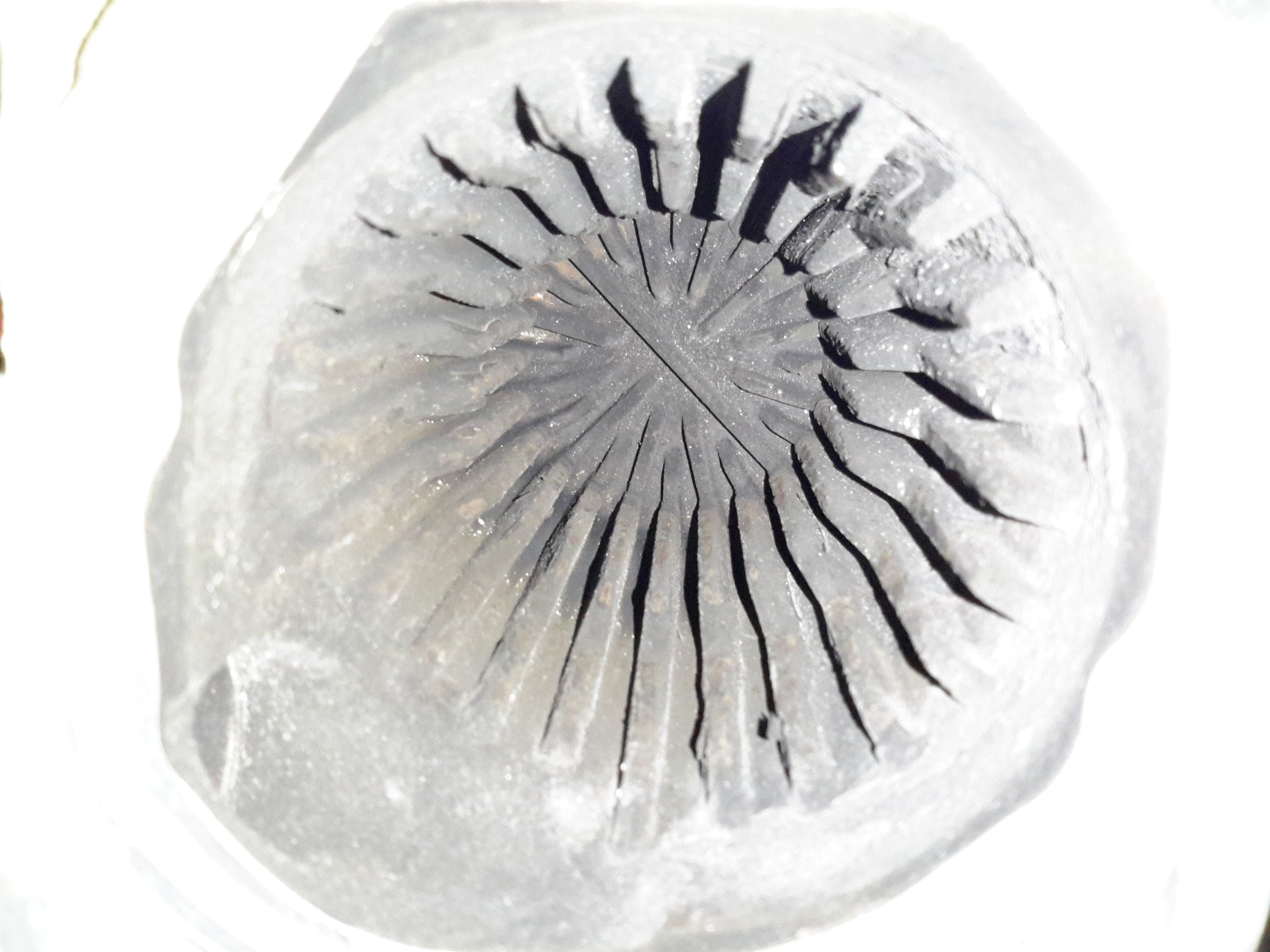
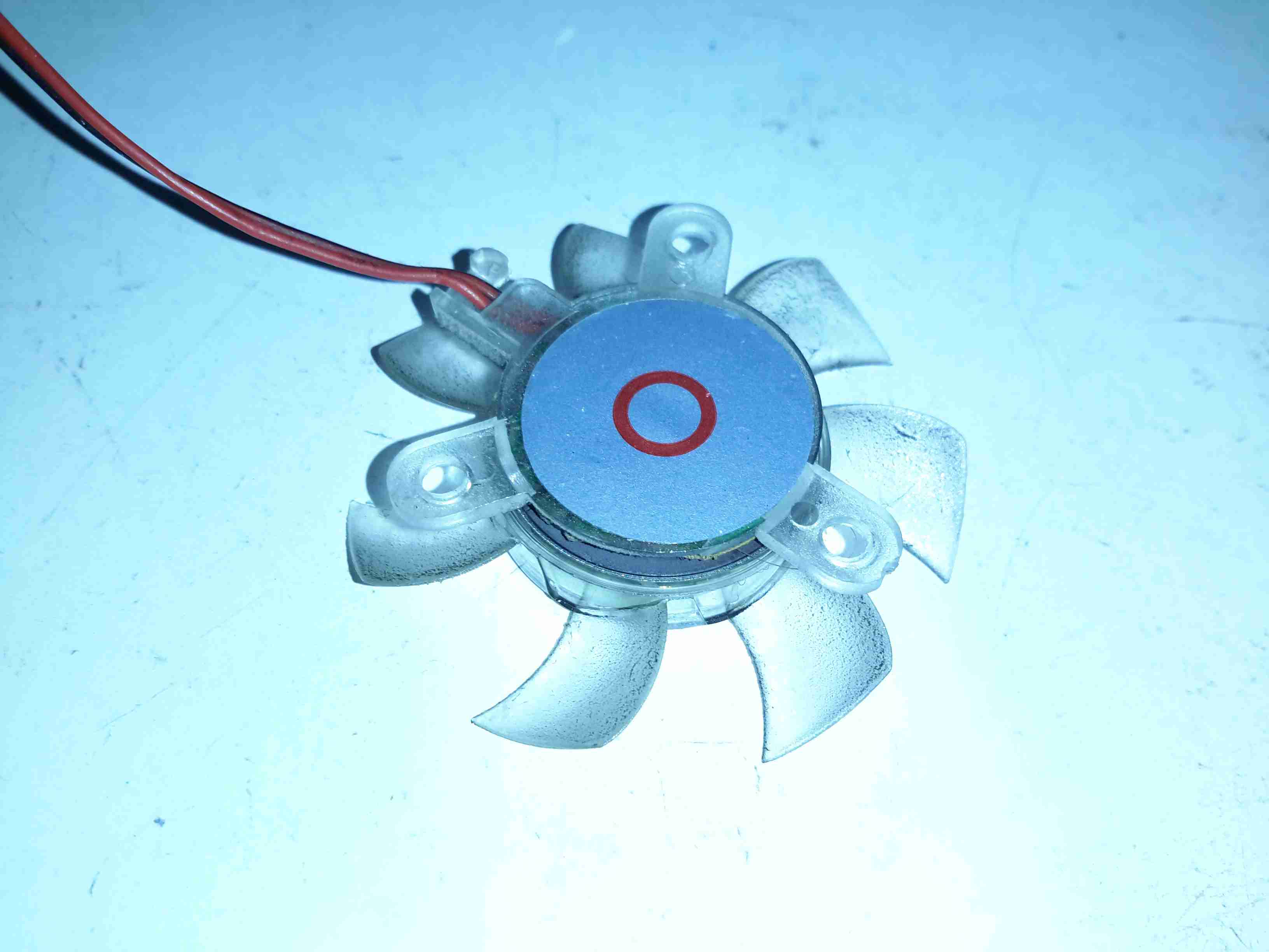
Fan Rear
Here’s the old fan removed from the heatsink. The back label, usally the place where I’d expect to find some specifications has nothing but a red circle. This really is the cheapest crap that the manufacturer could have fitted, and considering this HBA isn’t exactly cheap, I’d expect better.
Bearings
Peeling off the back label reveals the back of the bearing housing, with the plastic retaining clip. There’s some sign of heat damage here, the oil has turned into gum, all the lighter fractions having evaporated off.
Rotor
The shaft doesn’t show any significant damage, but since the phosphor bronze bearing is softer, there is some dirt in here which is probably a mix of degraded oil & bearing material.
Stator & Bearing
There’s more gunge around the other end of the bearing & it’s been worn enough that side play can be felt with the shaft. In ~3000 hours running this fan is totally useless.
I wrote a few weeks ago about replacing the hot water circulating pump on the boat with a new one, and mentioned that we’d been through several pumps over the years. After every replacement, autopsy of the pump has revealed the failure mode: the first pump failed due to old age & limited life of carbon brushes. The second failed due to thermal shock from an airlock in the system causing the boiler to go a bit nuts through lack of water flow. The ceramic rotor in this one just cracked.
The last pump though, was mechanically worn, the pump bearings nicely polished down just enough to cause the rotor to stick. This is caused by sediment in the system, which comes from corrosion in the various components of the system. Radiators & skin tanks are steel, engine block cast iron, back boiler stainless steel, Webasto heat exchanger aluminium, along with various bits of copper pipe & hose tying the system together.
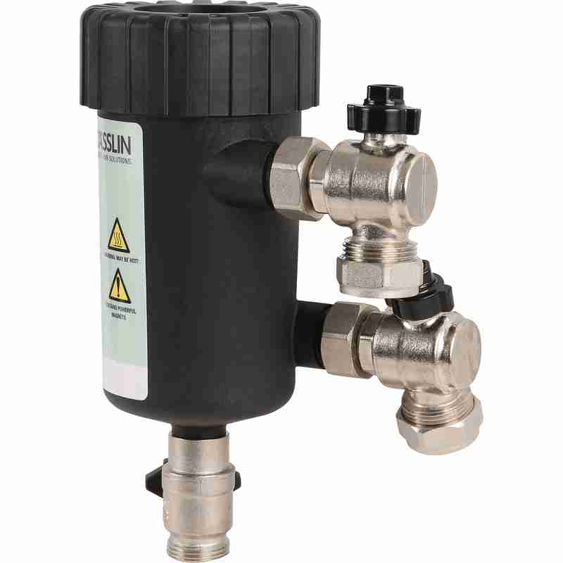
The use of dissimilar metals in a system is not particularly advisable, but in the case of the boat, it’s unavoidable. The antifreeze in the water does have anti-corrosive additives, but we were still left with the problem of all the various oxides of iron floating around the system acting like an abrasive. To solve this problem without having to go to the trouble of doing a full system flush, we fitted a magnetic filter:
Mag Filter
This is just an empty container, with a powerful NdFeB magnet inserted into the centre. As the water flows in a spiral around the magnetic core, aided by the offset pipe connections, the magnet pulls all the magnetic oxides out of the water. it’s fitted into the circuit at the last radiator, where it’s accessible for the mandatory maintenance.
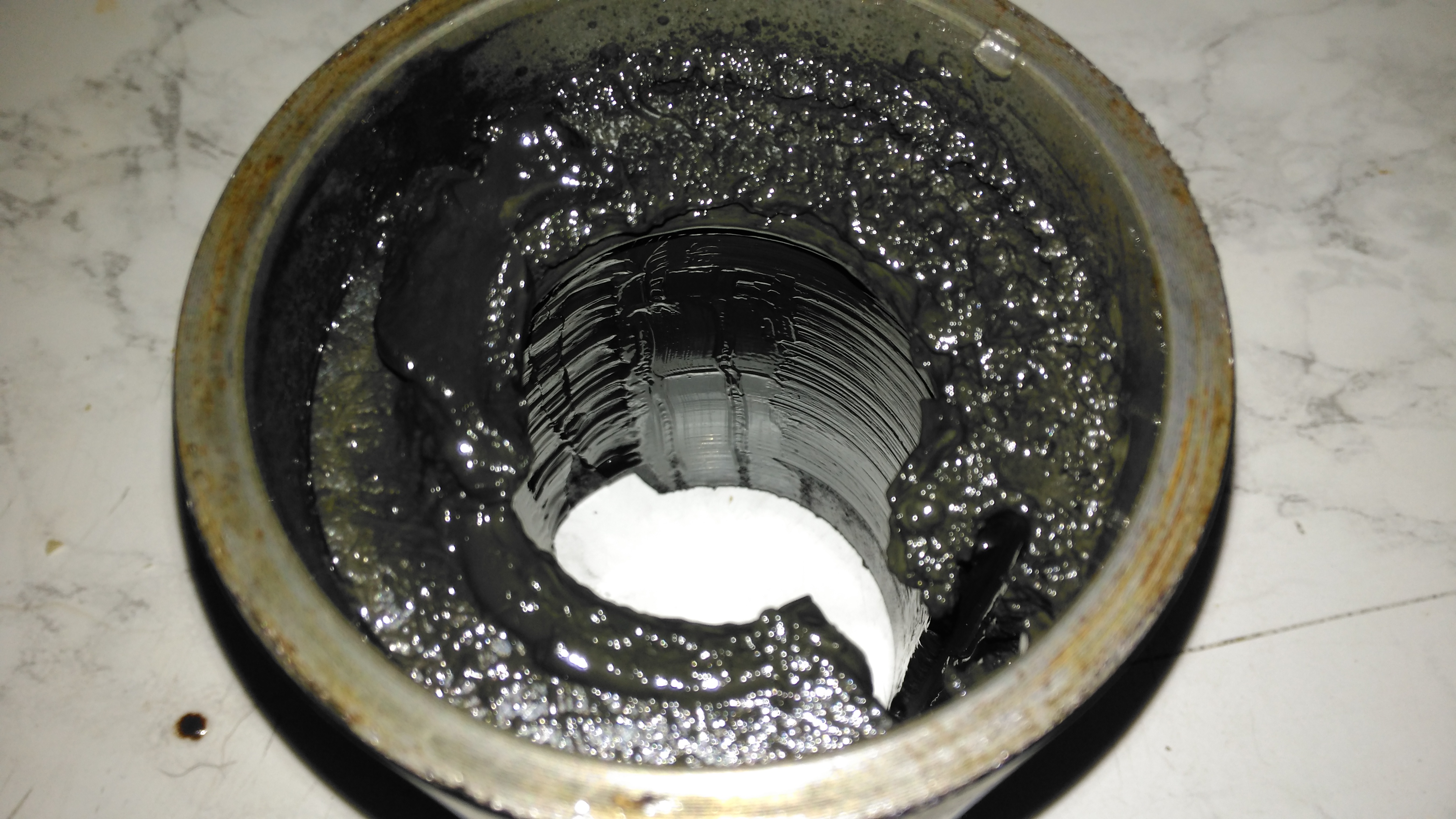
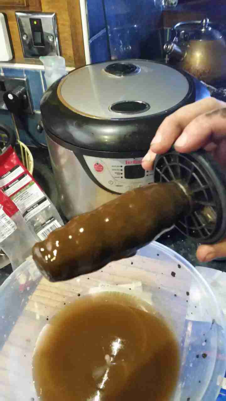
Sludge
Now the filter has been in about a month, I decided it would be a good time to see how much muck had been pulled out of the circuit. I was rather surprised to see a 1/2″ thick layer of sludge coating the magnetic core! The disgusting water in the bowl below was what drained out of the filter before the top was pulled. (The general colour of the water in the circuit isn’t this colour, I knocked some loose from the core of the filter while isolating it).
If all goes well, the level of sludge in the system will over time be reduced to a very low level, with the corrosion inhibitor helping things along. This should result in much fewer expensive pump replacements!
Some time ago I did a couple of posts on cheapening up the maintenance of Eberspacher hot air heaters by making the glow plug screens myself. Now one of my pieces of stainless mesh has been in the heater for nearly a year, and the heater is starting to get a bit smoky on a cold start. This is usually a sign that the screen isn’t allowing the fuel to vaporise quick enough for the glow plug to ignite the flame, because it’s becoming blocked. So far the heater has had about 150L of diesel through it with my DIY screen.
Old Screen
After removing the plug, here’s what’s left of the screen. The bottom end has completely disintegrated, but this is to be expected – OEM screens do the same thing as this end is exposed to the most heat in the burner. There’s quite a bit of coke buildup on the top end of the screen around the fuel nozzle, again this isn’t surprising, as this is the coolest part of the heater not all the heavier fractions of the diesel fuel have the chance to vaporise.
Innards
Looking further down into the mixing tube of the main burner, everything looks good. There’s a coating of soot in there, but no tar-like build up that would tell me the unit isn’t burning properly. Another advantage of making my own screens is that they’re much easier to extract from the hole once they’ve been in there for months. The OEM screens have a stainless ring spot welded to the mesh itself to hold it’s shape, and once there’s enough fuel residue built up the entire mess seizes in place, requiring some sharp pokey tools & some colourful language to remove. The single loop of mesh held in place by it’s own spring pressure is much easier to remove as it collapses easily.
New 80 Mesh Screen
I’ve decided to change the mesh size of the screen while I’m in here, in this case to 80 mesh, which is much closer to the OEM screen size. There doesn’t seem to be much of a difference so far in either the starting or running capability of the heater, although the thicker wire of this screen might last longer before disintegrating at the burner end.
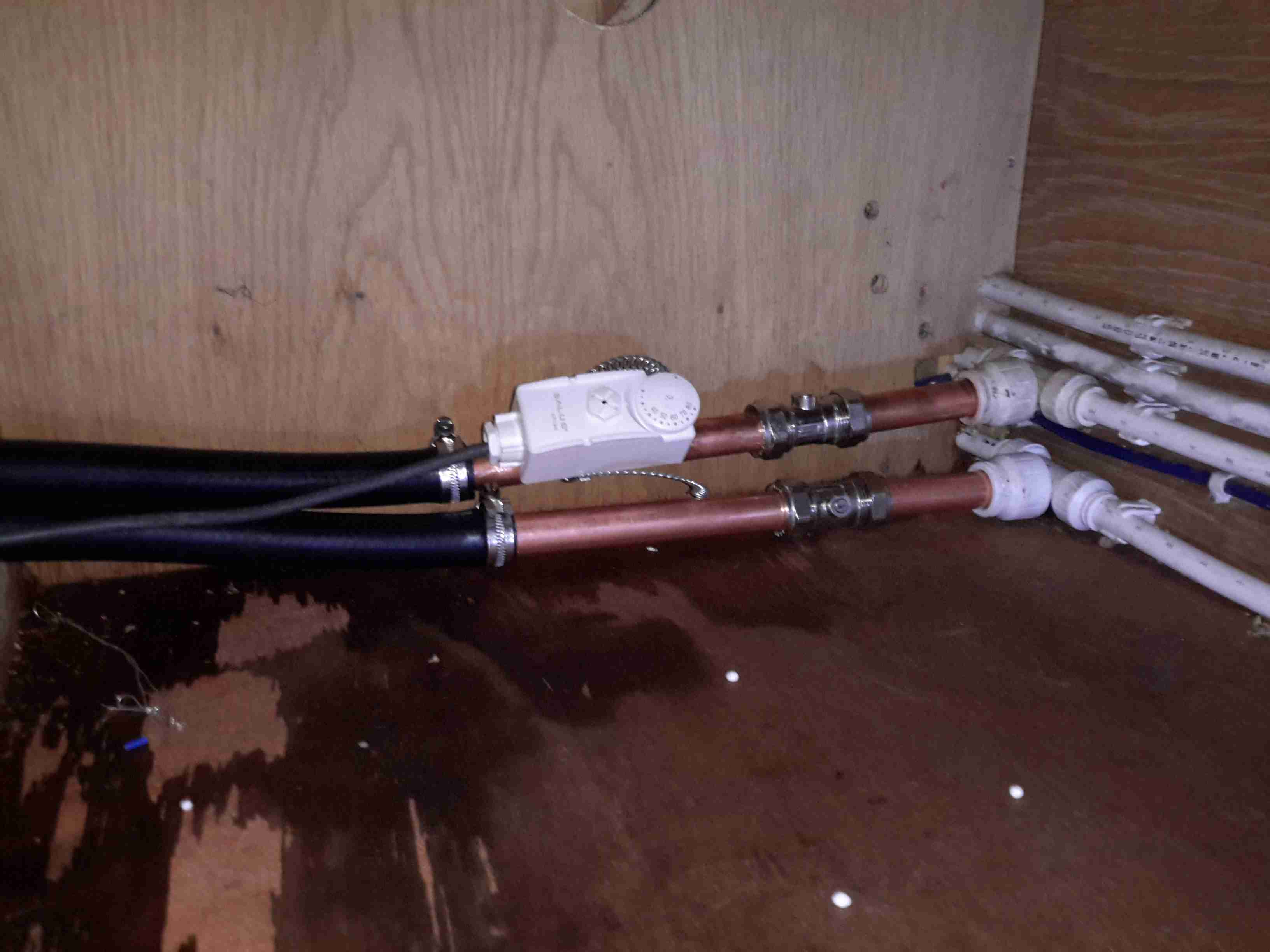
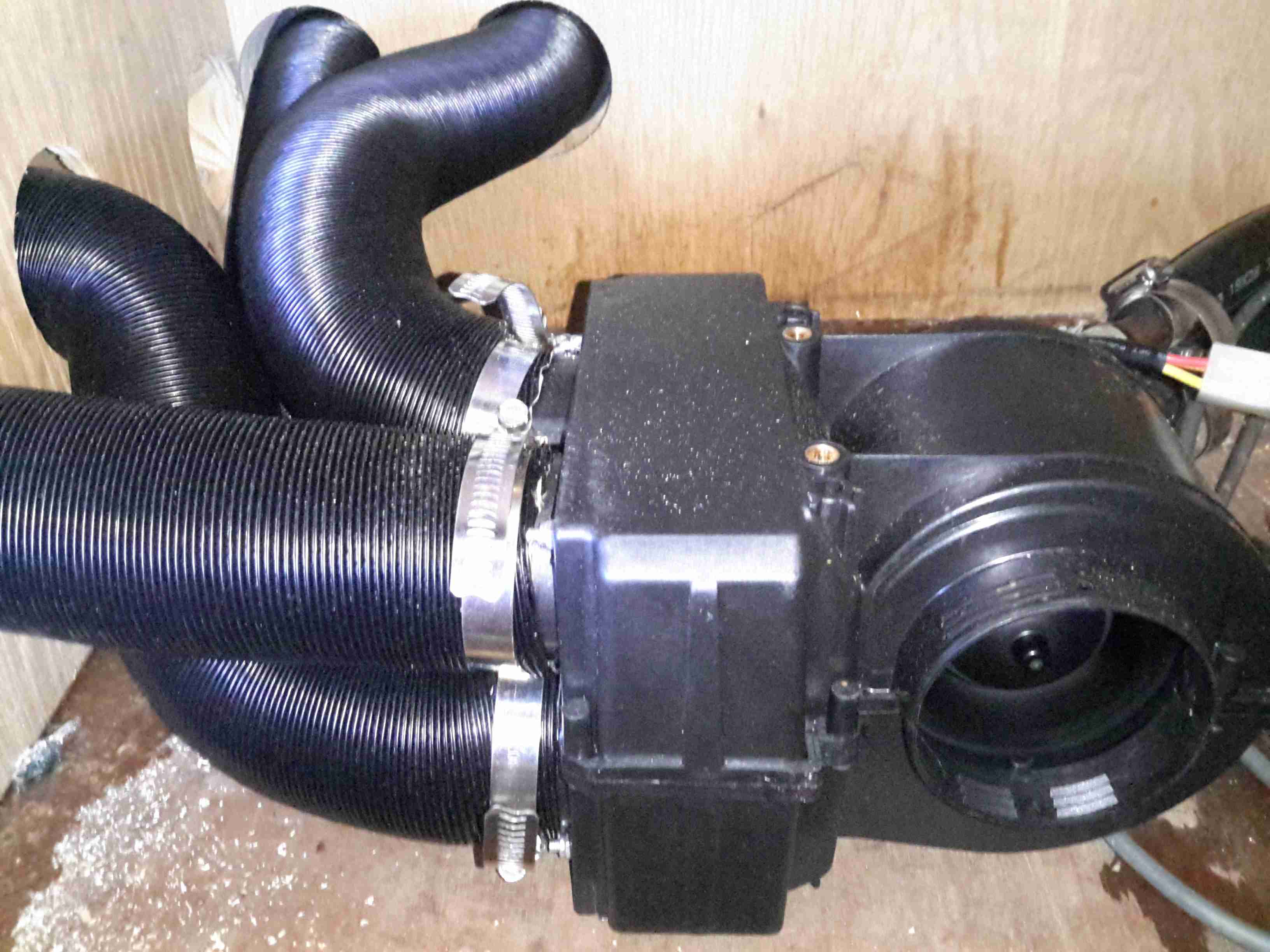
Here the pipework feeding the matrix of the blower unit has been tapped into the heating circuit, the first radiator on the loop is just out of shot to the right, this is all tucked away under the bed in one of the cabins. The pipestat is attached to the flow from the boiler, this will switch on the blower once hot water starts flowing through the system. Isolation valves have been fitted to make the inevitable maintenance of the matrix unit easier, as the system is pressurised to 14PSI, dropping the pressure out of the system without making quite a mess is difficult.
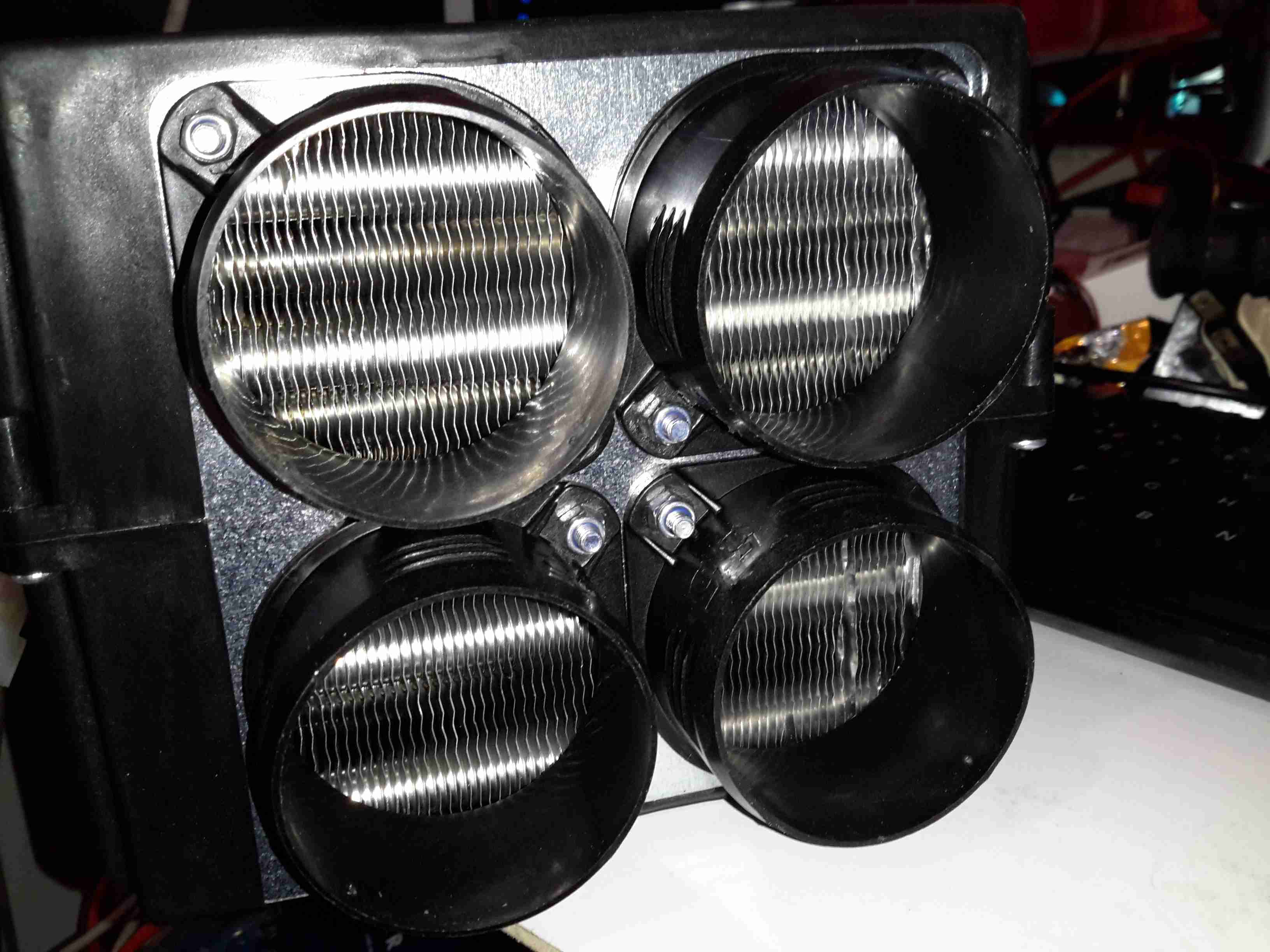
Heater Matrix & Ducting
The heater itself is mounted on the other side of a wooden partition in the small space left under a shelf. This made installing the unit like trying to plumb in a radiator through a letterbox ;). 4 60mm ducts snake off to the vents mounted in the wall.
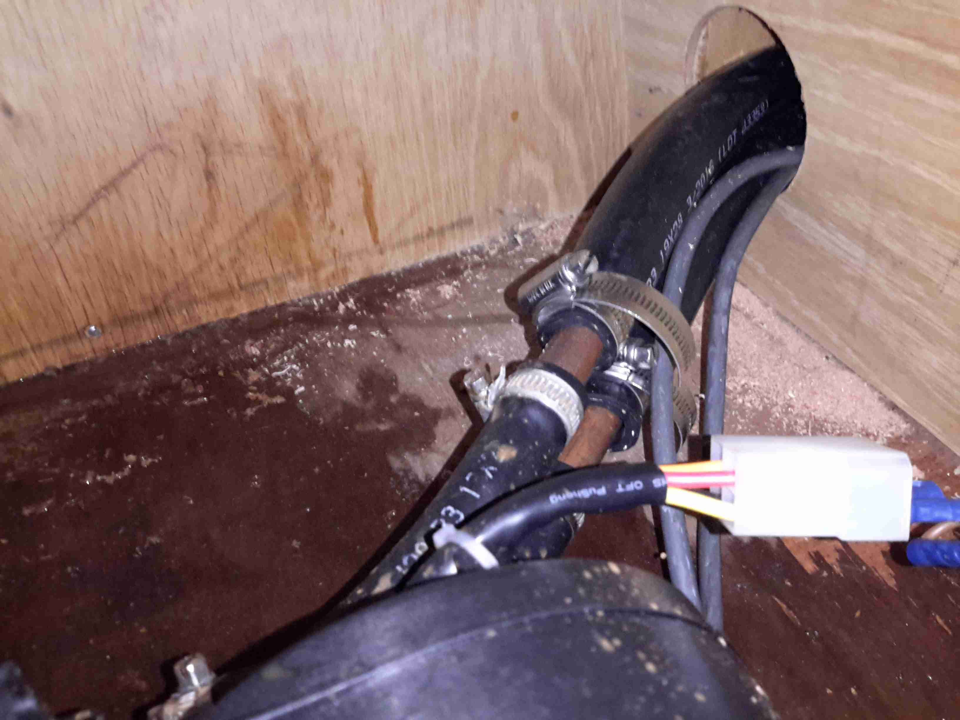
Water Connections
The hot water hoses appear through a hole in the timber to connect to the matrix unit, with some 15mm pipe in between as reducers from the 3/4″ hose to the 1/2″ attached to the matrix itself. The blower is wired in low speed mode only, as running it any faster makes far too much noise from the vents.
As a heating solution, this unit works well onboard. Within a 10 minutes of the diesel heater firing up, the blower automatically comes on thanks to the thermostat, and blows plenty of hot air into the saloon to keep the cold at bay.
With the installation of the new diesel fired heater we’ve noticed a small problem – since the only heat source in the saloon is the stove, even with the diesel heater fired up the temperature doesn’t really change much, as the heat from the radiators in the both the cabins & the head isn’t spreading far enough.
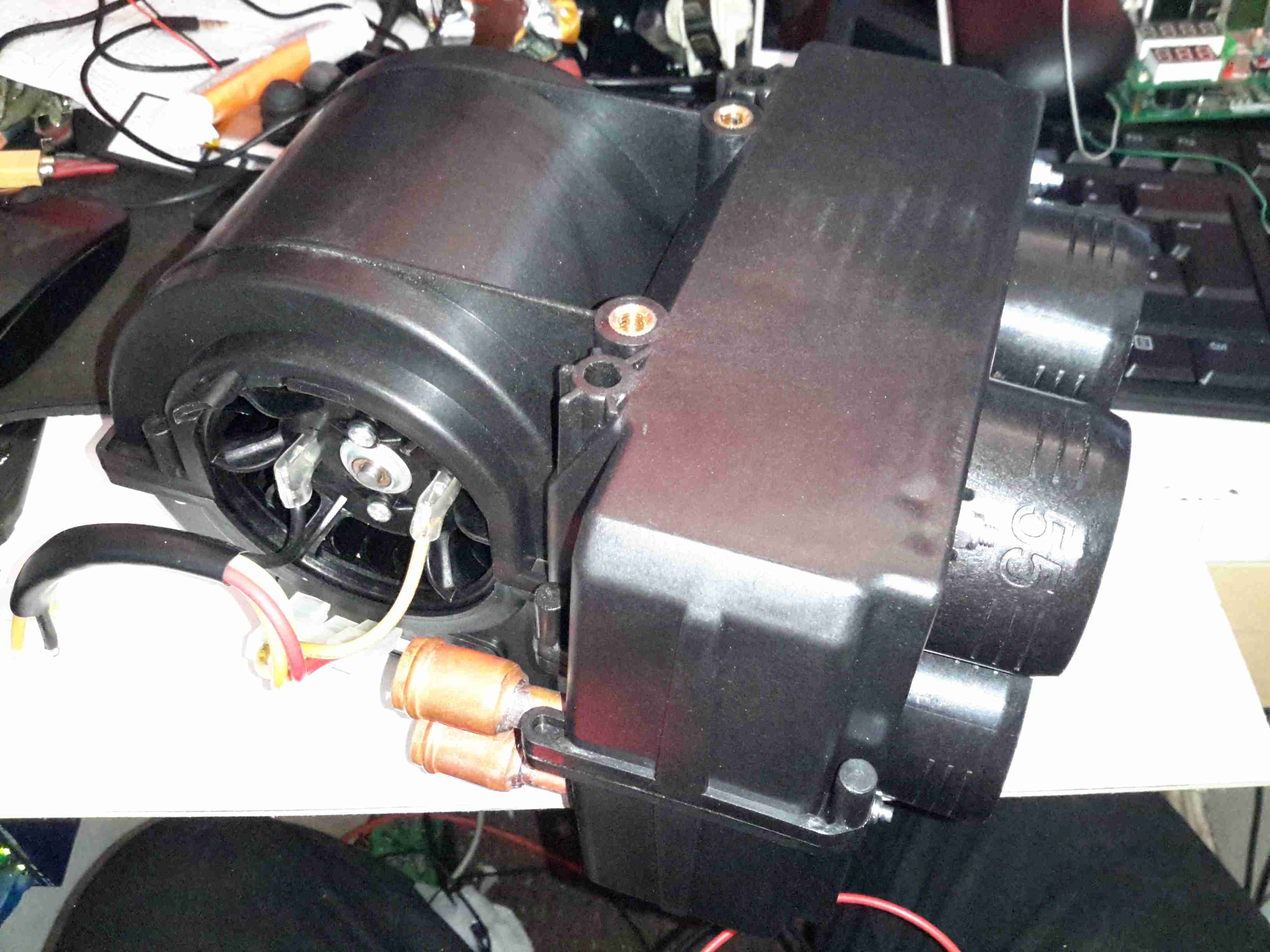
The solution to this problem is obviously an extra radiator in the saloon, however there isn’t the space to fit even a small domestic-style radiator. eBay turned up some heater matrix units designed for kit cars & the like:
3.8kW Matrix
These small heater matrix units are nice & compact, so will fit into the back of a storage cupboard next to the saloon. Rated at a max heat output of 3.8kW, just shy of the stove’s rated 4kW output power, this should provide plenty of heating when we’re running the diesel heater rather than the fire.
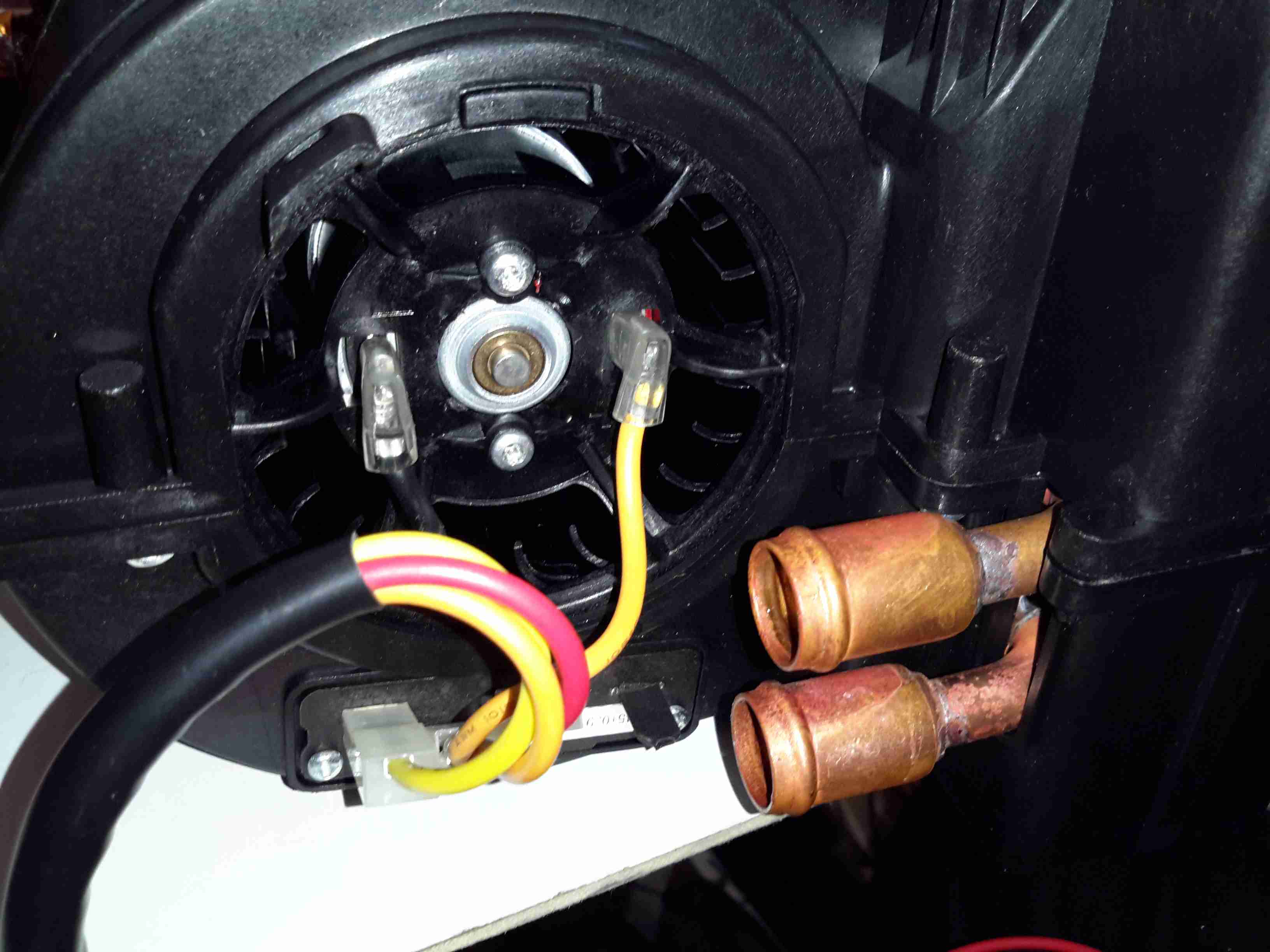
Water & Power
The blower motor has a resistor network to provide 3 speeds, but this probably won’t be used in this install, water connections are via 15mm copper tails. The current plan is to use a pipe thermostat on the flow from the boiler to switch on the blower when the water temperature reaches about 40°C.
Hot Air Outlets
The hot air emerges from the matrix via 4 55mm duct sockets. This gives enough outlets to cover both the saloon & the corridor down to the cabins.
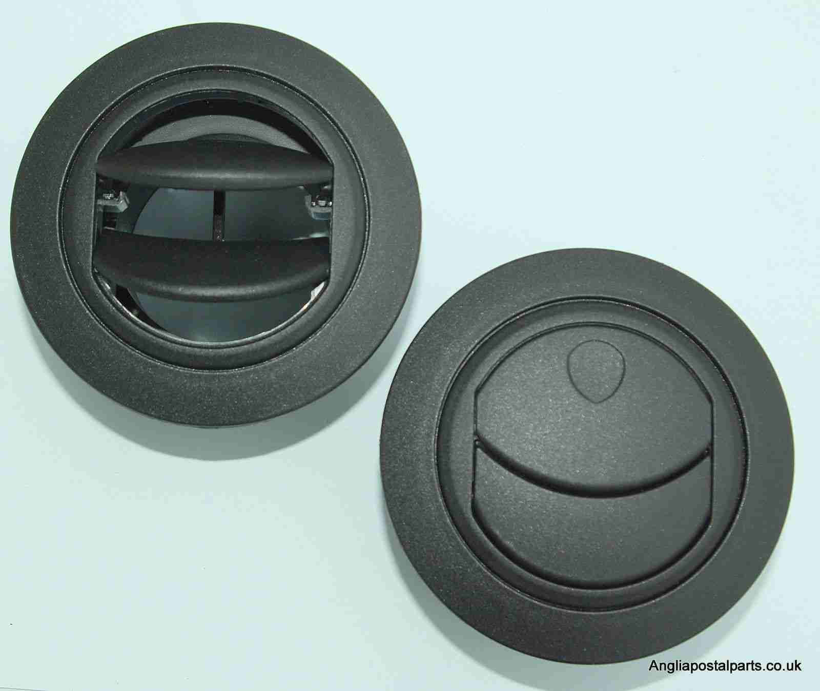
Hot Air Vents
Standard 60mm Eberspacher style vents will be used to point the warmth where it’s needed.
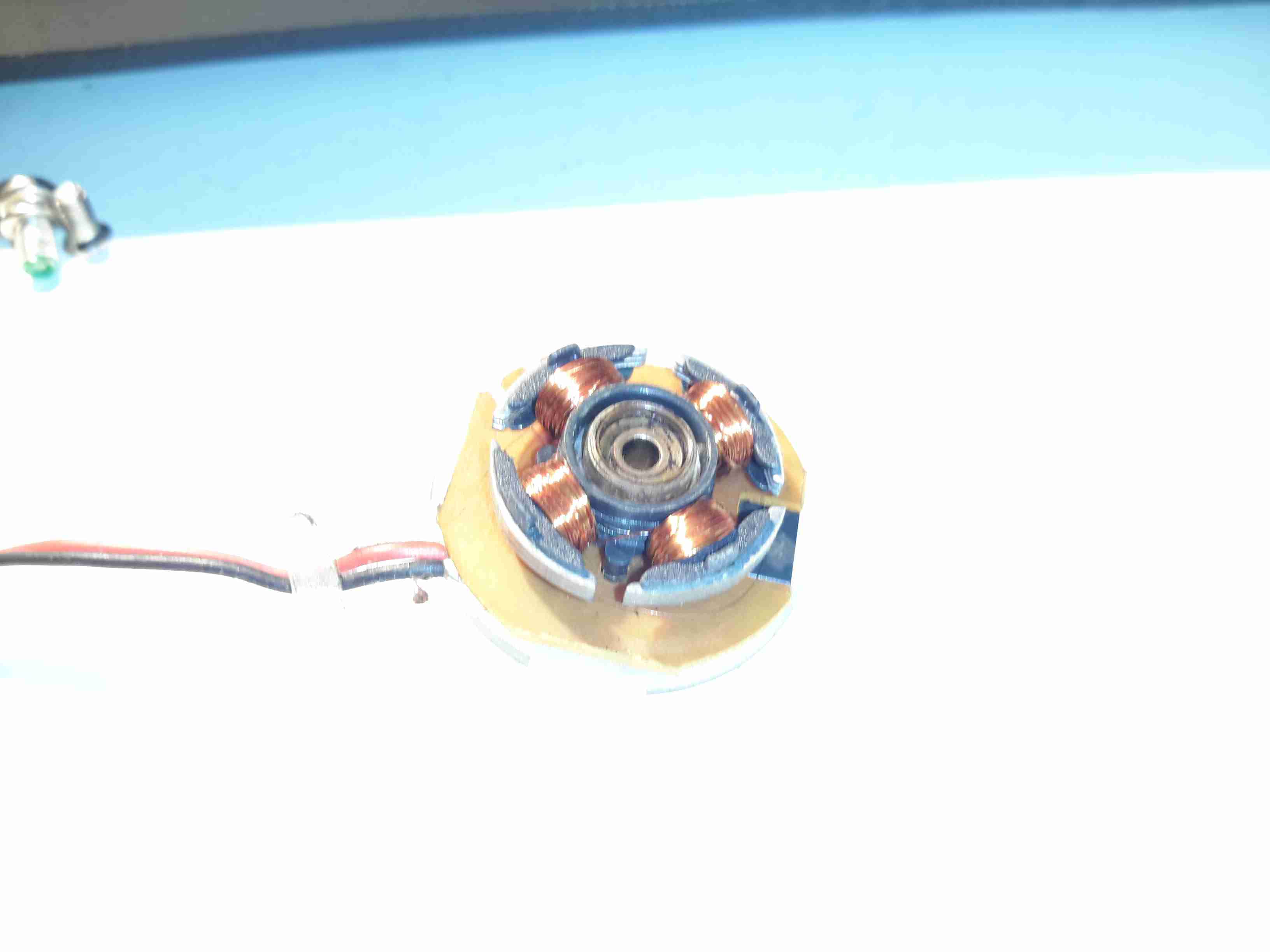
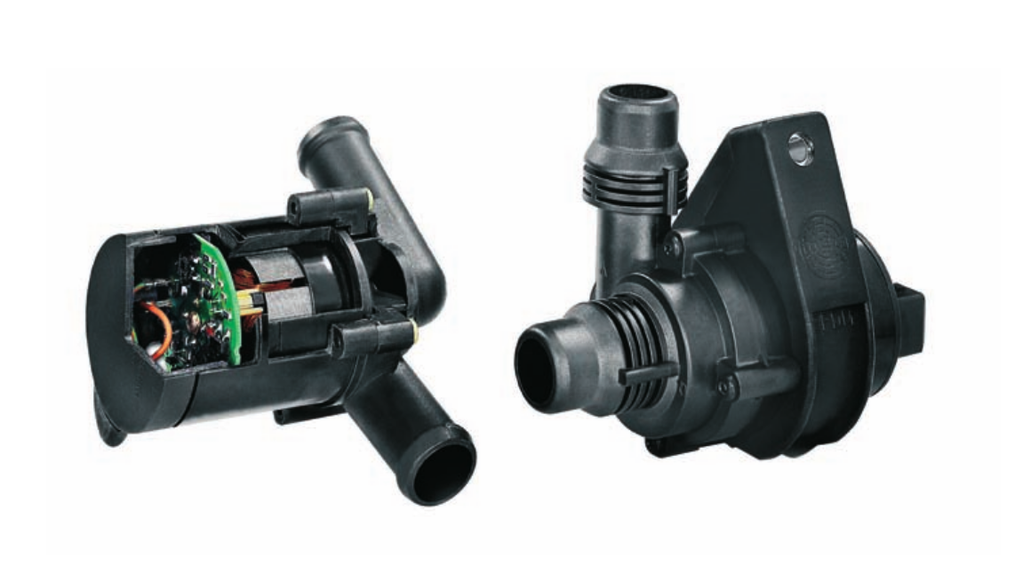
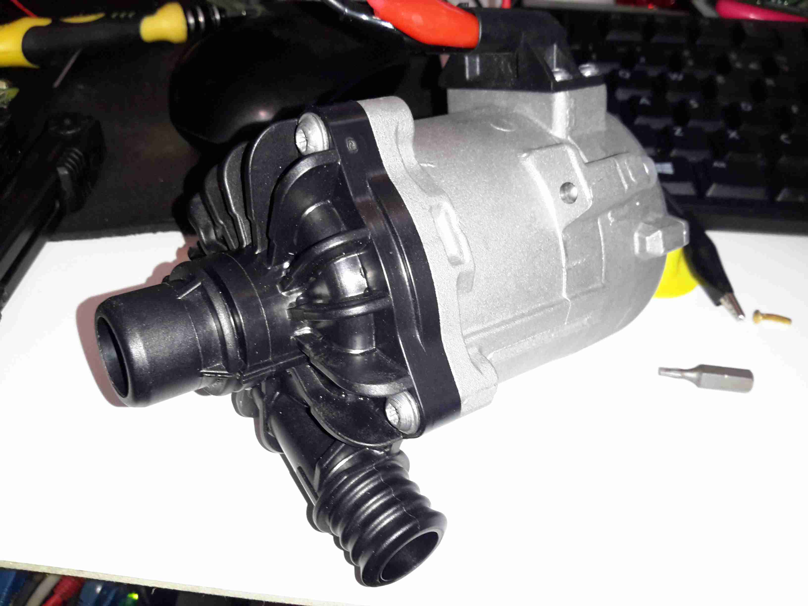
With some recent upgrades to the boat’s heating system, the hot water circulation pumps we’ve been using are becoming far too small for the job. After the original Johnson Marine circulation pump died of old age (the brushes wore down so far the springs ate the commutator) some time ago, it was replaced with a Pierburg WUP1 circulation pump from a BMW. (As we’re moored next to a BMW garage, these are easily obtainable & much cheaper than the marine pumps).
WUP1 Cutaway
These are also brushless, where as the standard Johnson ones are brushed PM motors – the result here is a much longer working life, due to fewer moving parts.
The rated flow & pressure on these pumps is pretty pathetic, at 13L/min at 0.1bar head pressure. As the boat’s heating system is plumbed in 15mm pipe instead of 22mm this low pressure doesn’t translate to a decent flow rate. Turns out it’s pretty difficult to shove lots of water through ~110ft of 15mm pipe ;). Oddly enough, the very low flow rate of the system was never a problem for the “high output” back boiler on the stove – I suspect the “high output” specification is a bit optimistic.
This issue was recently made worse with the addition of a Webasto Thermo Top C 5kW diesel-fired water heater, which does have it’s own circulation pump but the system flow rate was still far too low to allow the heater to operate properly. The result was a rapidly cycling heater as it couldn’t dump the generated hot water into the rest of the system fast enough.
The easiest solution to the problem here is a larger pump with a higher head pressure capability. (The more difficult route would be completely re-piping the system in 22mm to lower the flow resistance). Luckily Pierburg produce a few pumps in the range that would fit the job.
Pierburg CWA-50
Here’s the next size up from the original WUP1 pump, the CWA50. These are rated at a much more sensible 25L/min at 0.6bar head pressure. It’s physically a bit larger, but the connector sizes are the same, which makes the install onto the existing hoses easier. (For those that are interested, the hose connectors used on BMW vehicles for the cooling system components are NormaQuick PS3 type. These snap into place with an O-Ring & are retained by a spring clip).
The CWA50 draws considerably more power than the WUP1 (4.5A vs 1.5A), and are controllable with a PWM signal on the connector, but I haven’t used this feature. The PWM pin is simply tied to the positive supply to keep the pump running at maximum speed.
Once this pump was installed the head pressure immediately increased on the gauge from the 1 bar static pressure to 1.5 bar, indicating the pump is running at about it’s highest efficiency point. The higher water flow has so far kept the Webasto happy, there will be more to come with further improvements!
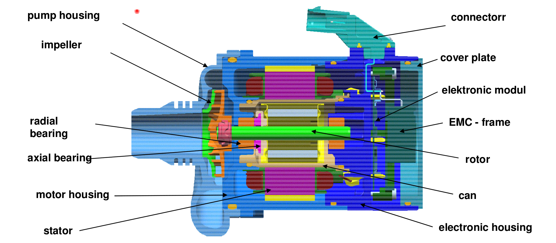
CWA-50 Pump Teardown
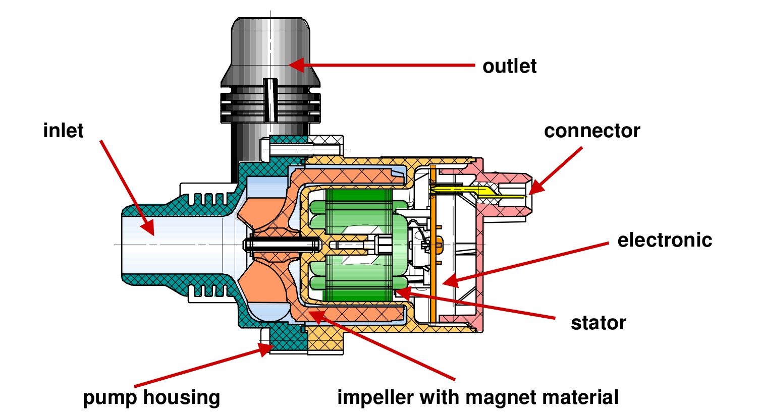
CWA50 Cutaway
Above is a cutaway drawing of the new pump. These have a drilling through the shaft allows water to pass from the high pressure outlet fitting, through the internals of the pump & returns through the shaft to the inlet. This keeps the bearings cool & lubricated. The control & power drive circuitry for the 3-phase brushless motor is attached to the back & uses the water flowing through the rotor chamber as a heatsink. Overall these are very well made pumps.
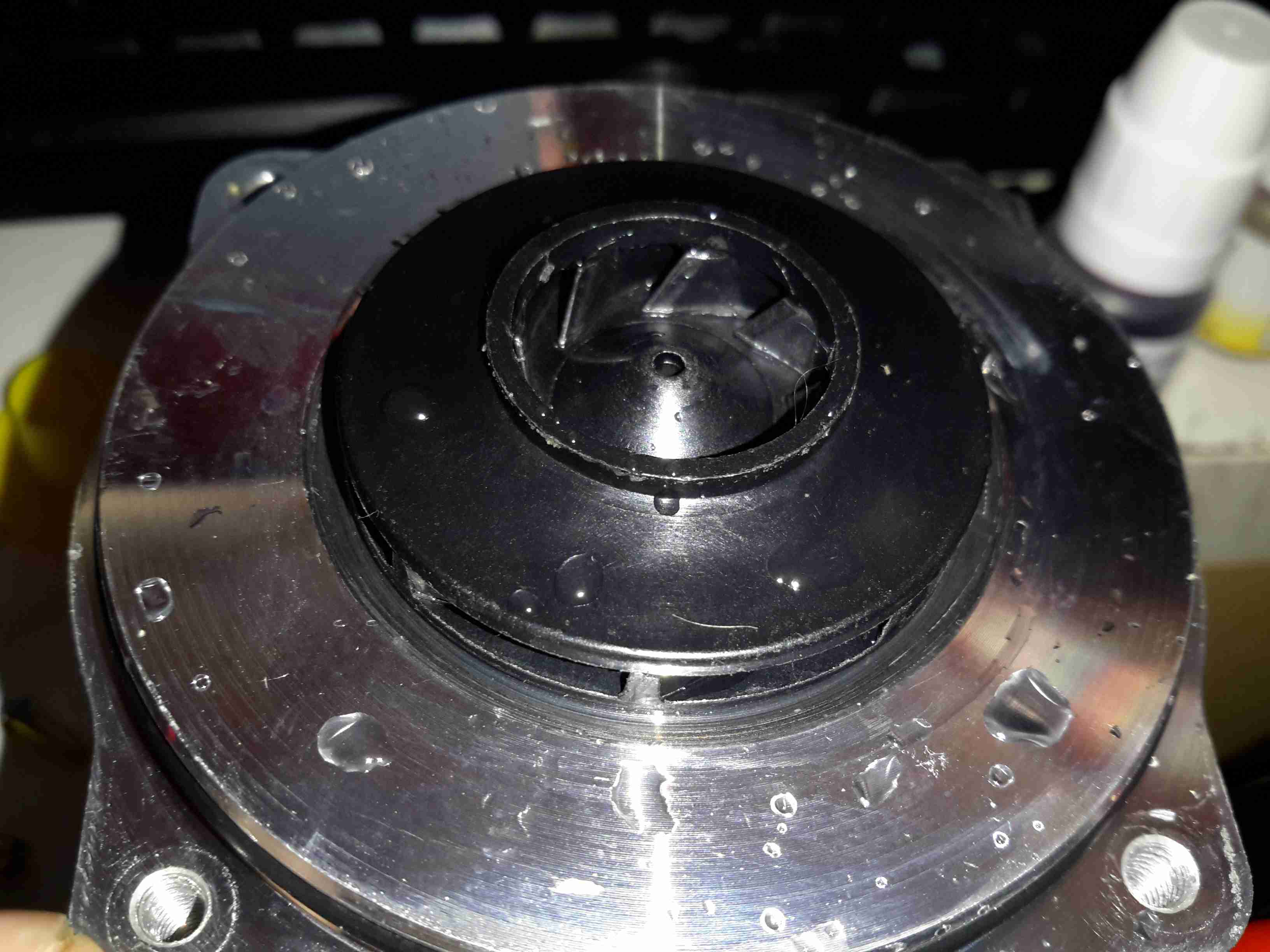
Impeller
Here’s the impeller of the pump, which is very small considering the amount of power this unit has. The return port for the lubricating water can be seen in the centre of the impeller face.
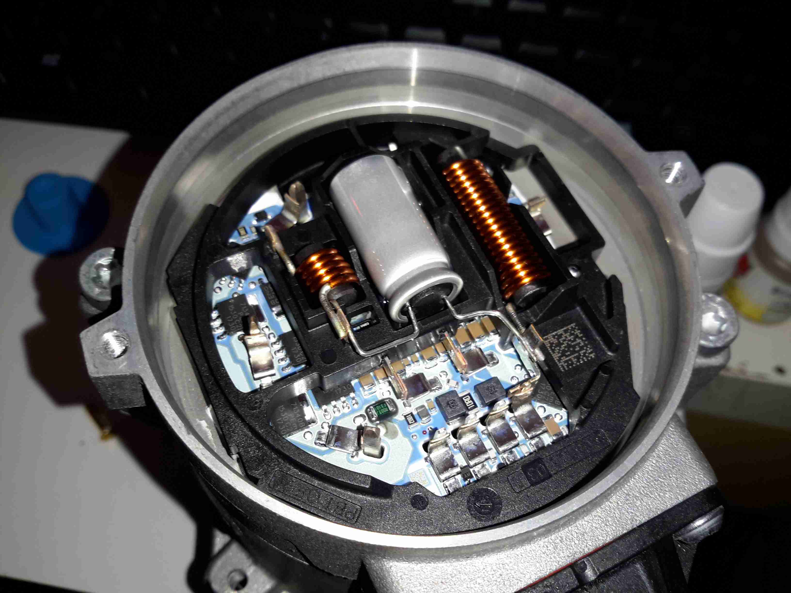
3-Phase Driver
Inside the back of the pump is the control module. The main microcontroller is hiding under the plastic frame which holds the large power chokes & the main filter electrolytic.
In a word, no they aren’t any good. As usual, cheap doesn’t equal good, and in this case the cheapo clones are a total waste of money. Read on for the details!
I’ve been looking into using a cheap Chinese clone Honda GX35 engine to drive an automotive alternator as a portable battery charging & power unit. These engines are available very cheaply on eBay, aimed at the mini-bike/go-kart market.
For those not in the know, the Honda GX25/35 4-strokes are strimmer-type engines that traditionally were always of 2-stroke construction. Honda worked out how to have a wet-sump engine without the need to keep the engine always in the “upright” position. They do not require mixing of oil into the fuel for lubrication as 2-strokes do, so should be much cleaner running.
So far I’ve had two of these cheap engines, as the first one died after only 4 hours run time, having entirely lost compression. At the time the engine was idling, no load, having been started from cold only a few minutes before. Having checked the valve clearances to make sure a valve wasn’t being held partially open, I deduced that the cause was broken piston rings. This engine was replaced by the seller, so I didn’t get a chance to pull it to bits to find out, but I decided to do a full teardown on the replacement to see where the cloners have cut corners.
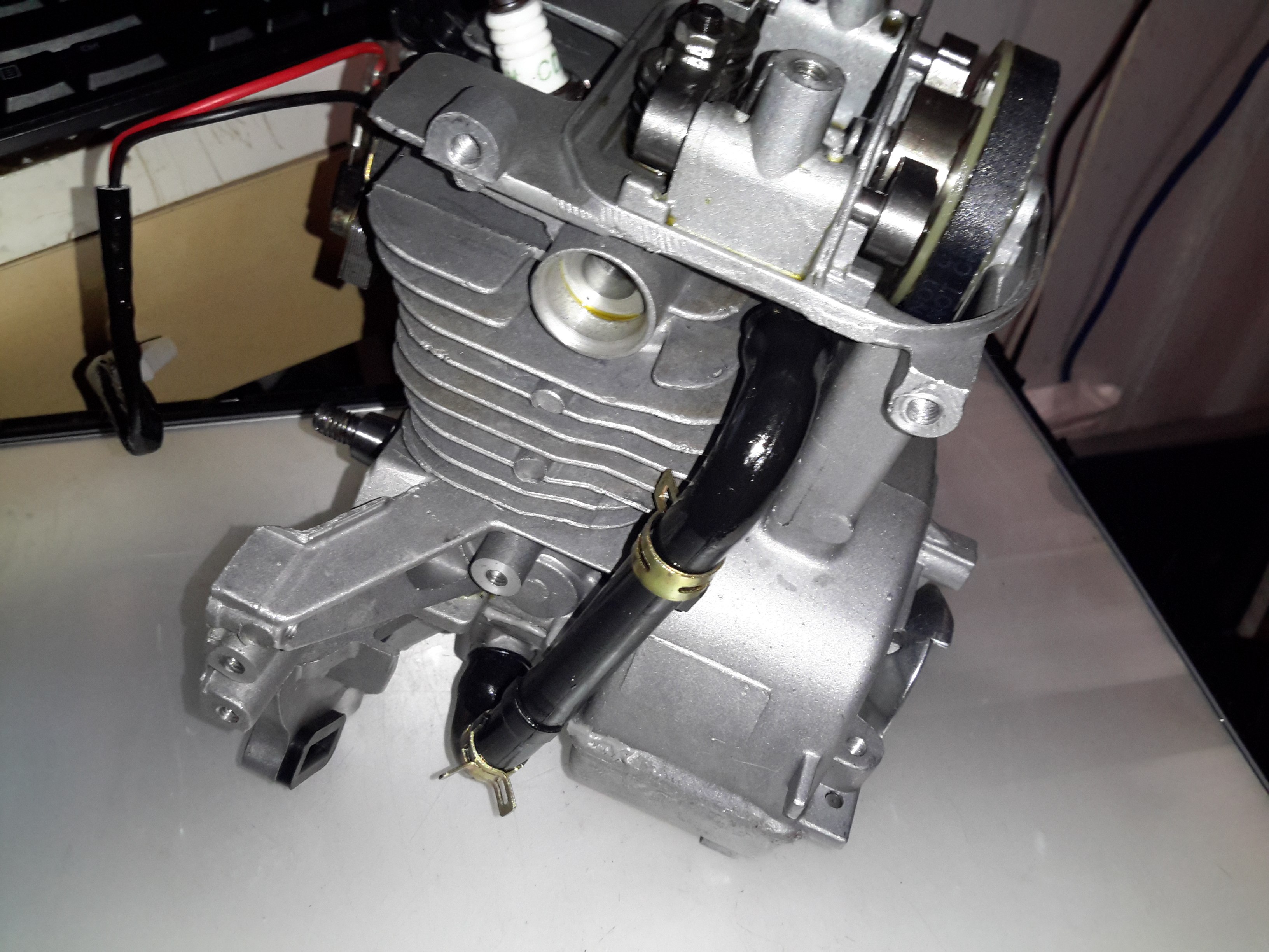
Oil Return Hose
I’ve already stripped off the ancillary components: exhaust, carburettor, fuel tank, cowlings, as these parts are standard to any strimmer engine. The large black hose here is the oil return feed back to the rocker cover from the crankcase. The oiling system in these engines is rather clever. The main engine block is made of light alloy, probably some permutation of Aluminium. There is much flashing left behind between the cylinder fins from the die-casting process, and not a single engine manufacturer’s logo anywhere. (From what I’ve read, the genuine Honda ones have their logo on the side of the crankcase).
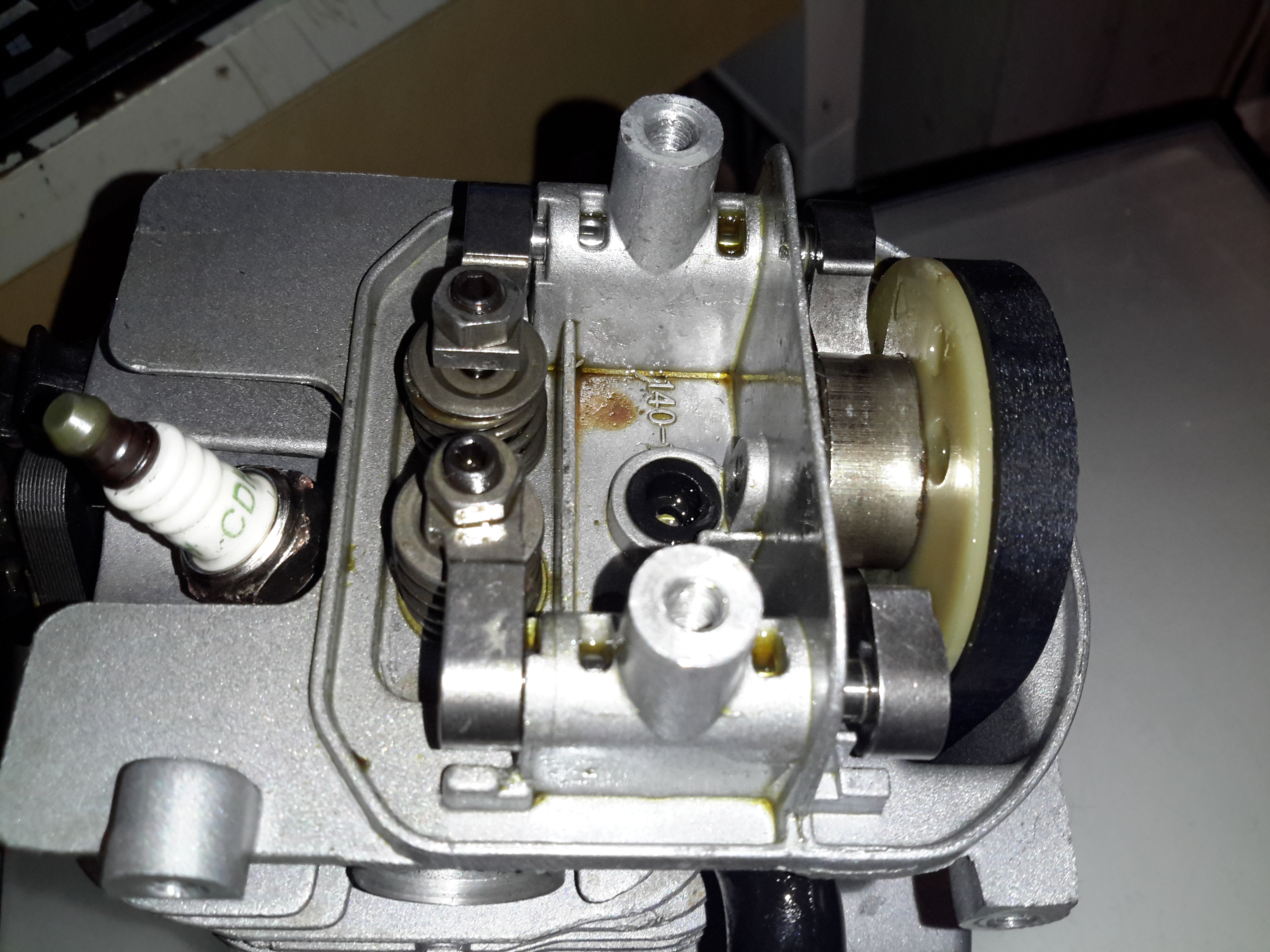
Rocker Box
Here’s the top of the engine with valves, rockers & camshaft. All the valve gear up here, minus the valves themselves & springs, are manufactured from sintered steel, there are no proper “bearings”, the steel shafts just run in the aluminium castings. The cam gear is of plastic, with the sintered steel cam pressed into place. The cam also has the bearing surface for the pin that the whole assembly rotates on. The timing belt runs in the oil & is supposed to last the life of the engine, and while I’d believe that in the original Honda, I certainly wouldn’t in this engine. The black grommet is the opening of the oil return gallery.
Cam
Here’s the cam on the back of the plastic pulley. A single cam is used for both intake & exhaust valves for space & simplicity.
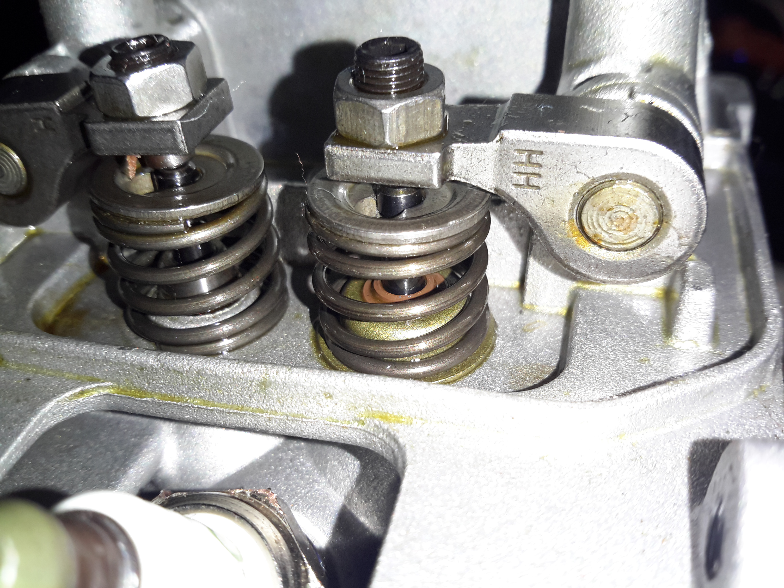
Intake Valve Stem Seal
Just visible under the intake valve spring is a simple stem seal, to hopefully prevent oil being sucked down the valve guide into the cylinder by intake vacuum. Running these cheap engines proves this seal to be ineffective, as they blow about as much blue oil smoke as a 2-stroke when they’re started cold. 😉
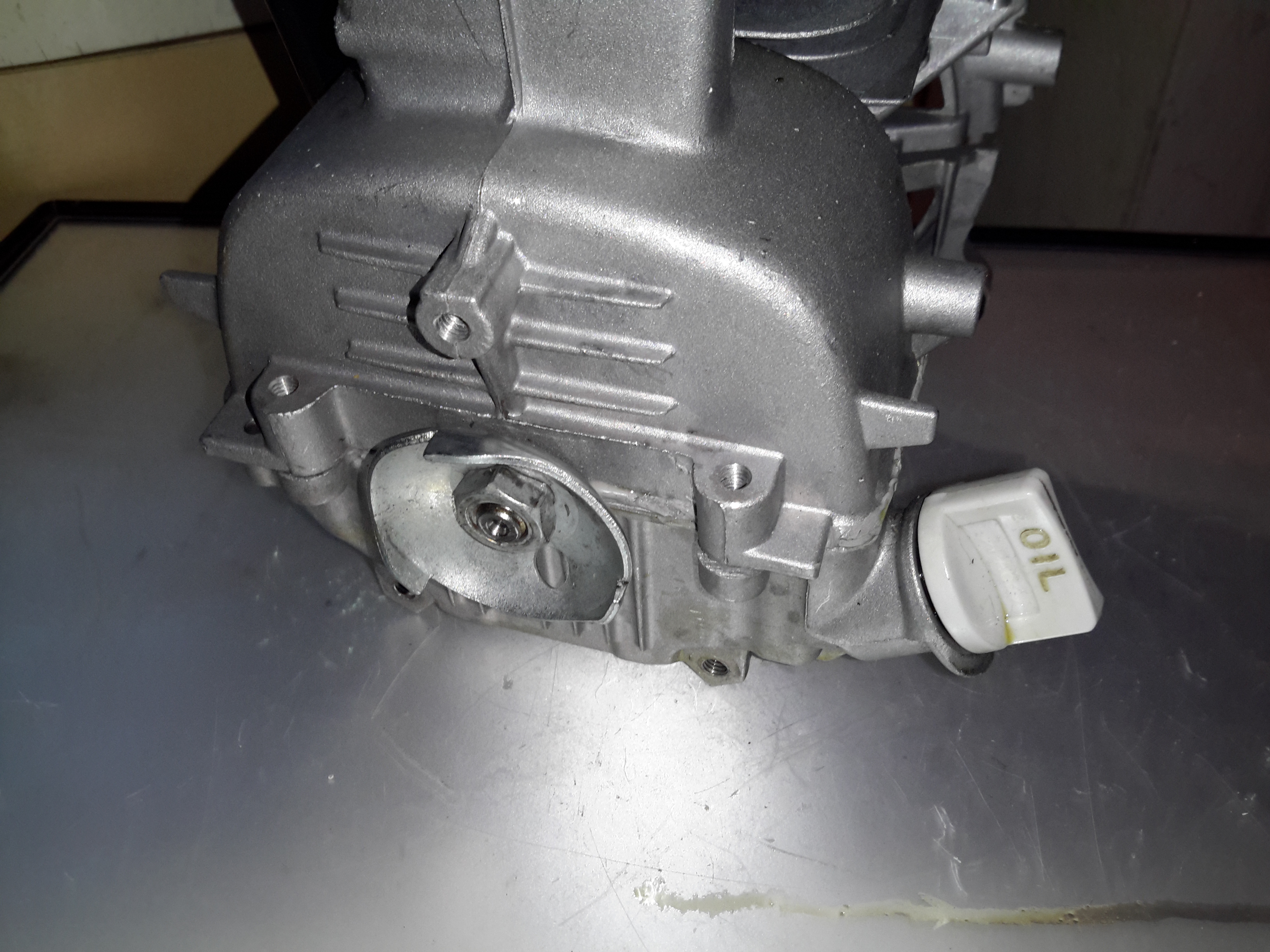
Starter Side
The starter side is where the oil sump is located on these engines, along with the dipstick.
Flywheel Side
The flywheel end of the engine is the usual fare for small engines. Ignition is provided by a magneto, with a magnet in the flywheel. This is no different from the 2-stroke versions. As these ignitions fire on every revolution of the crankshaft, the spark plug fires both on compression, igniting the fuel for normal operation, and again into the exhaust stroke, where the spark is wasted.
One thing I have noticed about these engines is an almost total lack of cooling air coming through the cowling over the cylinder cooling fins. Plenty was flowing over the exhaust silencer side, I believe bad housing design would be what causes this problem. A lack of cooling certainly wouldn’t help engine longevity!
Engine “Sump”
Separating the bottom of the engine was a little difficult, as there is a significant bead of sealant used instead of a gasket. Inside the sump of the engine are a pair of paddles, which stir up the oil into a mist. As the piston moves in the cylinder, it acts as a pump, creating alternating pulses of pressure & vacuum in the crankcase. Oil mist flows through a drilling in the crank from the sump, into the crankcase where it (hopefully) lubricates the bearings & the cylinder wall. Incidentally, the only main bearings are on the crankcase – the far end of the shaft that carries the oil paddles & timing belt is just flapping in the breeze, the only support being the oil seal in the outer housing. The crank itself isn’t hardened – a file easily removes metal from all parts that I could get at. The big end journal pin might be, but these cranks are pressed together so I can’t access that part.
Lubrication Gallery
The oil mist feeds into the crankcase through this hollow section of shaft, there’s a drilling next to the timing belt pulley to connect the two spaces together.
Lower Crankcase
The lower crankcase is just a simple die casting, there’s a check valve at the bottom under the crankshaft to transfer oil to the rocker cover, through the rubber tube on the outside of the engine. After the oil reaches the rocker box, it condenses & returns to the sump via the timing belt cavity.
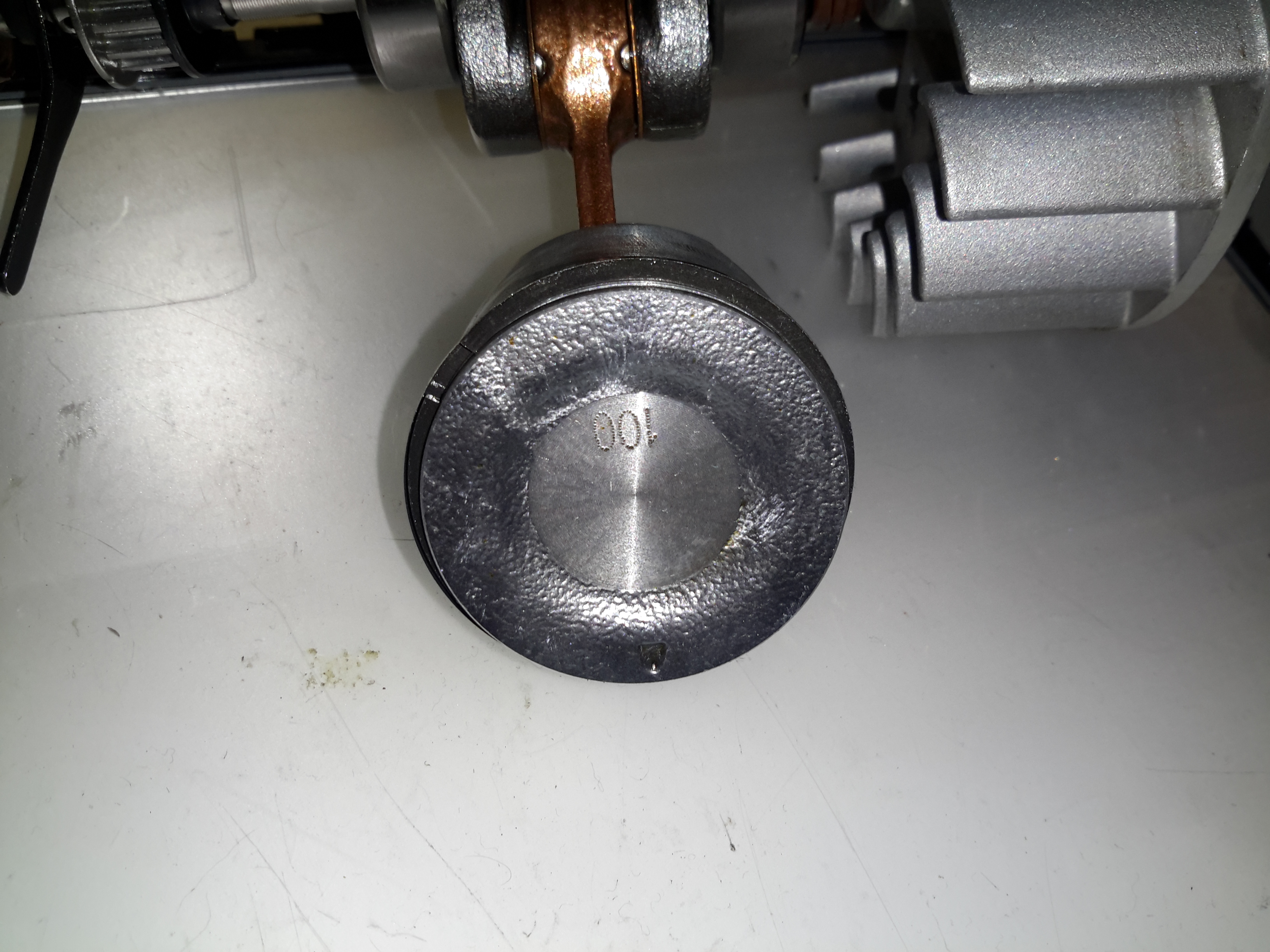
Piston Crown
Removing the crankshaft from the engine block gives me a look at the piston. The factory couldn’t even be arsed to machine the crown, it’s still got the rough finish from the hot-forging press. This bad finish will pick up much carbon from combustion, and would probably cause detonation once enough had accumulated to become incandescent in the heat of combustion. Only the centre is machined, just enough for them to stamp a number on.
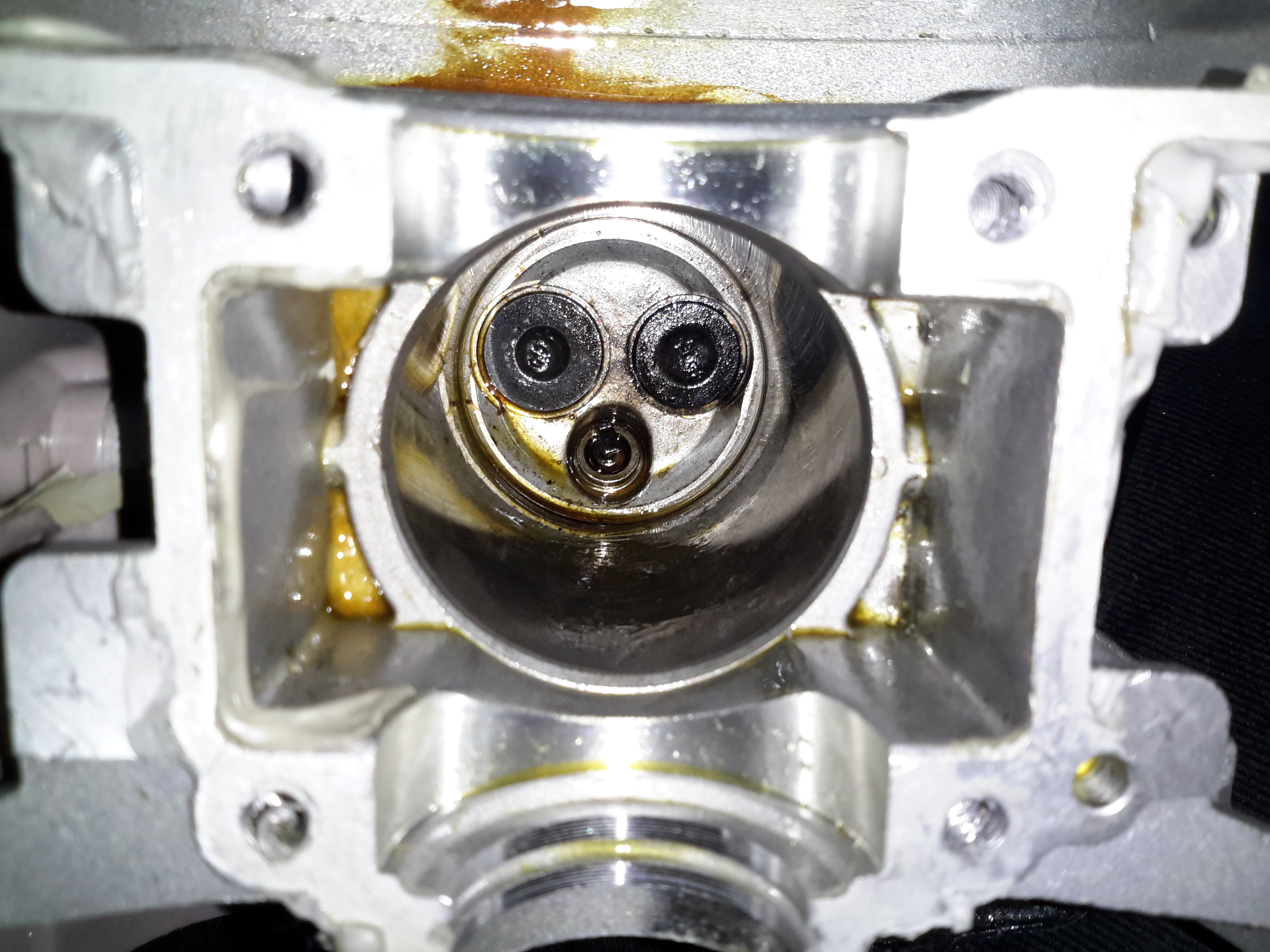
Cylinder Bore
A look up the cylinder bore shows the valves in the cylinder head. These engines, like their 2-stroke cousins have a single casting instead of a separate block & head, so getting at the valves is a little more of a pain. The cylinder bore itself is a cast-in iron liner and it’s totally smooth – like a mirror finish. There’s not a single sign of a crosshatch pattern from honing. If the first engine that died on me was the same – I’d be surprised if it wasn’t, this could easily cause ring breakage. The usual crosshatch pattern the cylinder hone produces holds oil, to better help lubricate the piston & rings. Without sufficient lubrication, the rings will overheat & expand far enough to close the end gap. Once this happens they will break.
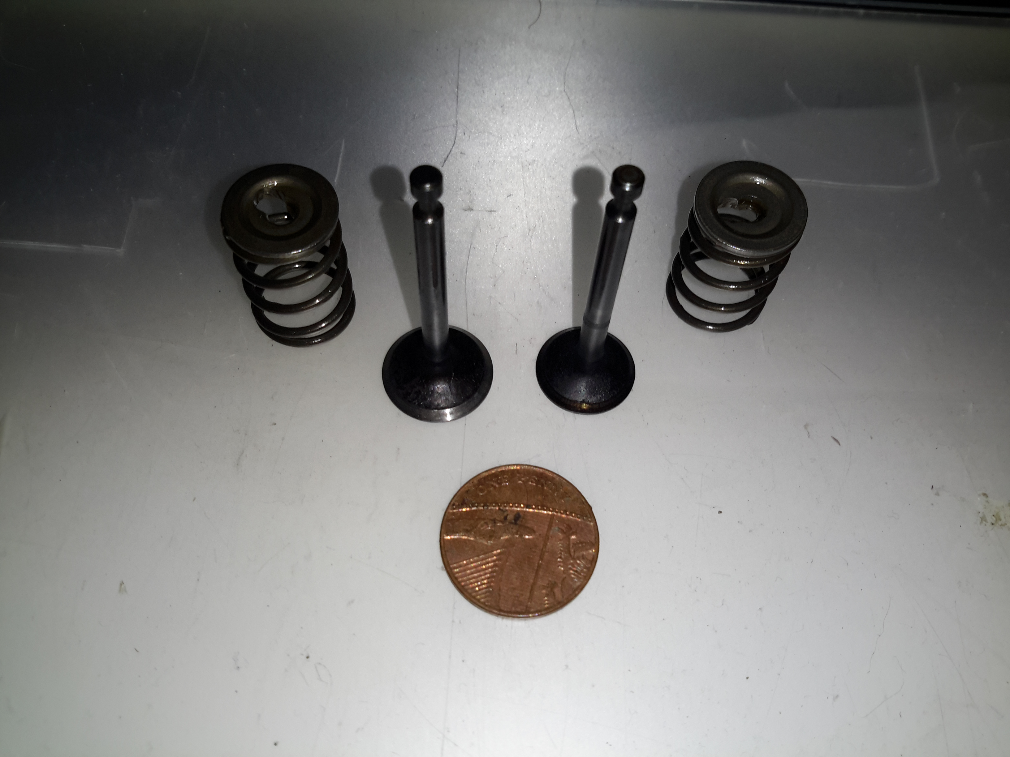
Engine Valves
Finally, here’s the valves with their springs removed from the cylinder. These are the smallest poppet valves I’ve ever seen, a British penny is provided for scale.
In all, these engines share many components with the older 2-stroke versions. The basic crankshaft & connecting rod setup is the same as I’ve seen in many old 2-strokes previous, the addition of the rather ingenious oiling system by Honda is what makes these tiny 4-strokes possible. I definitely won’t be trusting these very cheap copies in any of my projects, reliability is questionable at the least. The apparent lack of cooling air flow over the cylinder from the flywheel fan is concerning, along with the corner-cutting on the cylinder finishing process & piston crown, presumably to reduce factory costs.
I’ve been running my own VPN so I can access my home-based servers from anywhere with an internet connection (not to mention, in this day & age of Government snooping – personal privacy & increased security).
I’m on a pretty quick connection from Virgin Media here in the UK, currently the fastest they offer:
Virgin Media
To do these tests, I used the closest test server to my VPN host machine, in this case Paris. This keeps the variables to a minimum. Testing without the VPN connection gave me this:
Paris Server Speed
I did expect a lower general speed to a server further away, this will have much to do with my ISP’s traffic management, network congestion, etc. So I now have a baseline to test my VPN throughput against.
The problem I’ve noticed with OpenVPN stock configs are that the connections are painfully slow – running over UDP on the usual port of 1194 the throughput was pretty pathetic:
Stock Config Speed
I did some reading on the subject, the first possible solution being to change the send/receive buffers so they’re set to a specific value, rather than letting the system handle them. I also added options to get the server to push these values to the clients, this saving me the trouble of having to reissue all the client configurations.
Unfortunately just this option didn’t work as well as I’d like, downstream speeds jumped to 25Mb/s. In the stock config, the tunnel MTU & MSSFIX settings aren’t bothered with, some adjustment to set the tunnel MTU to lower than the host link MTU (in my case the standard 1500) prevents packet fragmentation, MSSFIX let’s the client TCP sessions know to limit the packet sizes it sends so that after OpenVPN has done the encryption & encapsulation, the packets do not exceed the set size. This also helps prevent packet fragmentation.
tun-mtu 1400
mssfix 1360
VPN Tweaked
After adjusting these settings, the download throughput over the VPN link has shot up to 136Mb/s. Upload throughput hasn’t changed as this is limited by my connection to Virgin Media. Some more tweaking is no doubt possible to increase speeds even further, but this is fine for me at the moment.
Tip Jar
If you’ve found my content useful, please consider leaving a donation by clicking the Tip Jar below!
All collected funds go towards new content & the costs of keeping the server online.