The old Panasonic NV-M5 has the standard for the time CRT based viewfinder assembly, which will happily take a composite video signal from an external source.
This viewfinder has many more connections than I would have expected, as it has an input for the iris signal, which places a movable marker on the edge of the display. This unit also has a pair of outputs for the vertical & horizontal deflection signals, I imagine for sync, but I’ve never seen these signals as an output on a viewfinder before.
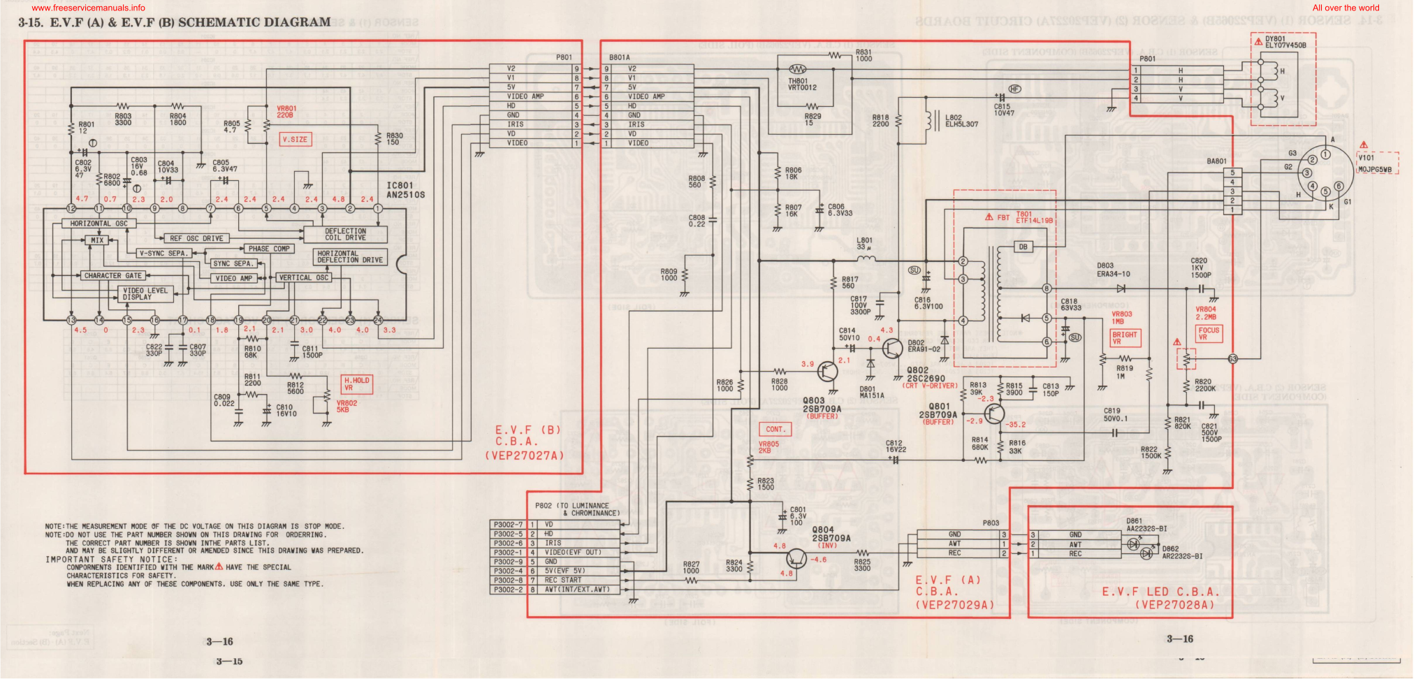
EVF Schematic
Luckily I managed to get a service manual for the camera with a full schematic.
This unit takes a 5v input, as opposed to the 8-12v inputs on previous cameras, so watch out for this! There’s also no reverse polarity protection either.
Pins
Making the iris marker vanish from the screen is easy, just put a solder bridge between pins 15 & 16 of the drive IC. The important pins on the interface connector are as follows:
Pin 3: GND
Pin 4: Video Input
Pin 5: Video GND
Pins 6: +5v Supply
For some time now I’ve been running a large disk array to store all the essential data for my network. The current setup has 10x 4TB disks in a RAID6 array under Linux MD.
Up until now the disks have been running in external Orico 9558U3 USB3 drive bays, through a PCIe x1 USB3 controller. However in this configuration there have been a few issues:
Congestion over the USB3 link. RAID rebuild speeds were severely limited to ~20MB/s in the event of a failure. General data transfer was equally as slow.
Drive dock general reliability. The drive bays are running a USB3 – SATA controller with a port expander, a single drive failure would cause the controller to reset all disks on it’s bus. Instead of losing a single disk in the array, 5 would disappear at the same time.
Cooling. The factory fitted fans in these bays are total crap – and very difficult to get at to change. A fan failure quickly allows the disks to heat up to temperatures that would cause failure.
Upgrade options difficult. These bays are pretty expensive for what they are, and adding more disks to the USB3 bus would likely strangle the bandwidth even further.
Disk failure difficult to locate. The USB3 interface doesn’t pass on the disk serial number to the host OS, so working out which disk has actually failed is difficult.
To remedy these issues, a proper SATA controller solution was required. Proper hardware RAID controllers are incredibly expensive, so they’re out of the question, and since I’m already using Linux MD RAID, I didn’t need a hardware controller anyway.
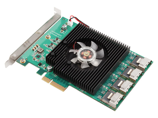
16-Port HBA
A quick search for suitable HBA cards showed me the IOCrest 16-port SATAIII controller, which is pretty low cost at £140. This card breaks out the SATA ports into standard SFF-8086 connectors, with 4 ports on each. Importantly the cables to convert from these server-grade connectors to standard SATA are supplied, as they’re pretty expensive on their own (£25 each).
This card gives me the option to expand the array to 16 disks eventually, although the active array will probably be kept at 14 disks with 2 hot spares, this will give a total capacity of 48TB.
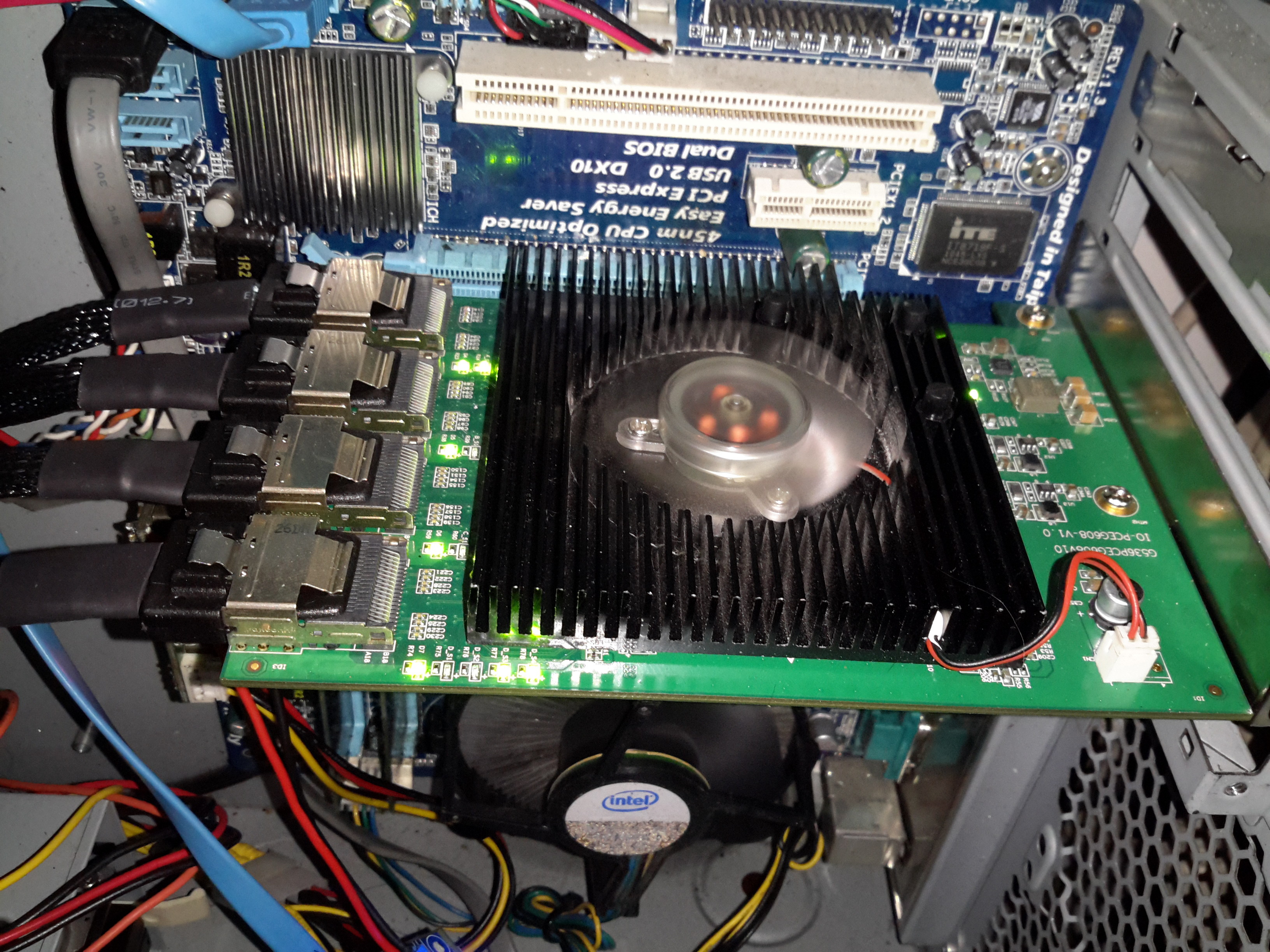
SATA HBA
Here’s the card installed in the host machine, with the array running. One thing I didn’t expect was the card to be crusted with activity LEDs. There appears to be one LED for each pair of disks, plus a couple others which I would expect are activity on the backhaul link to PCIe. (I can’t be certain, as there isn’t any proper documentation anywhere for this card. It certainly didn’t come with any ;)).
I’m not too impressed with the fan that’s on the card – it’s a crap sleeve bearing type, so I’ll be keeping a close eye on this for failure & will replace with a high quality ball-bearing fan when it finally croaks. The heatsink is definitely oversized for the job, with nothing installed above the card barely gets warm, which is definitely a good thing for life expectancy.
Update 10/02/17 – The stock fan is now dead as a doornail after only 4 months of continuous operation. Replaced with a high quality ball-bearing 80mm Delta fan to keep things running cool. As there is no speed sense line on the stock fan, the only way to tell it was failing was by the horrendous screeching noise of the failing bearings.
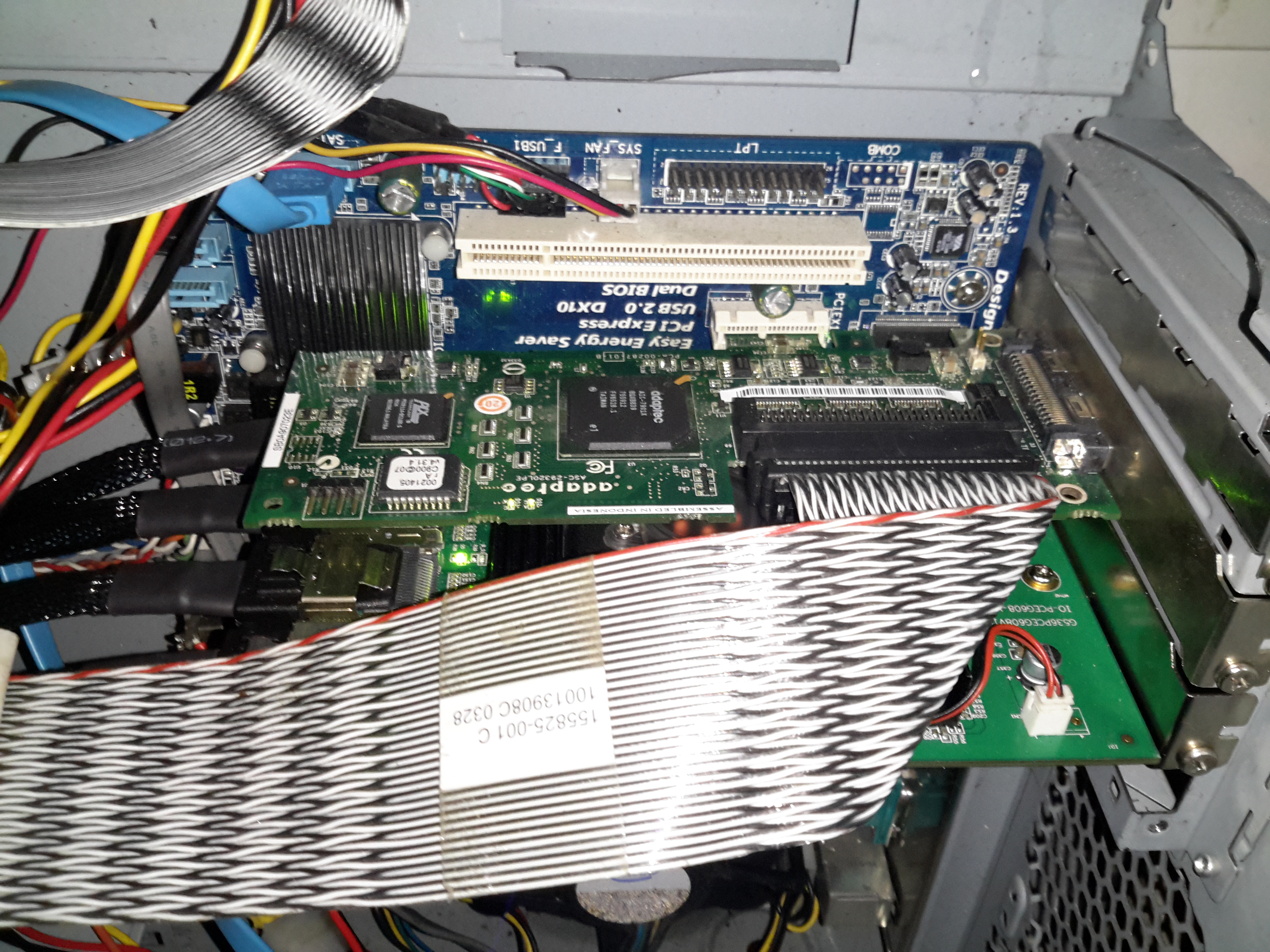
SCSI Controller
Above is the final HBA installed in the PCIe x1 slot above – a parallel SCSI U320 card that handles the tape backup drives. This card is very close to the cooling fan of the SATA card, and does make it run warmer, but not excessively warm. Unfortunately the card is too long for the other PCIe socket – it fouls on the DIMM slots.
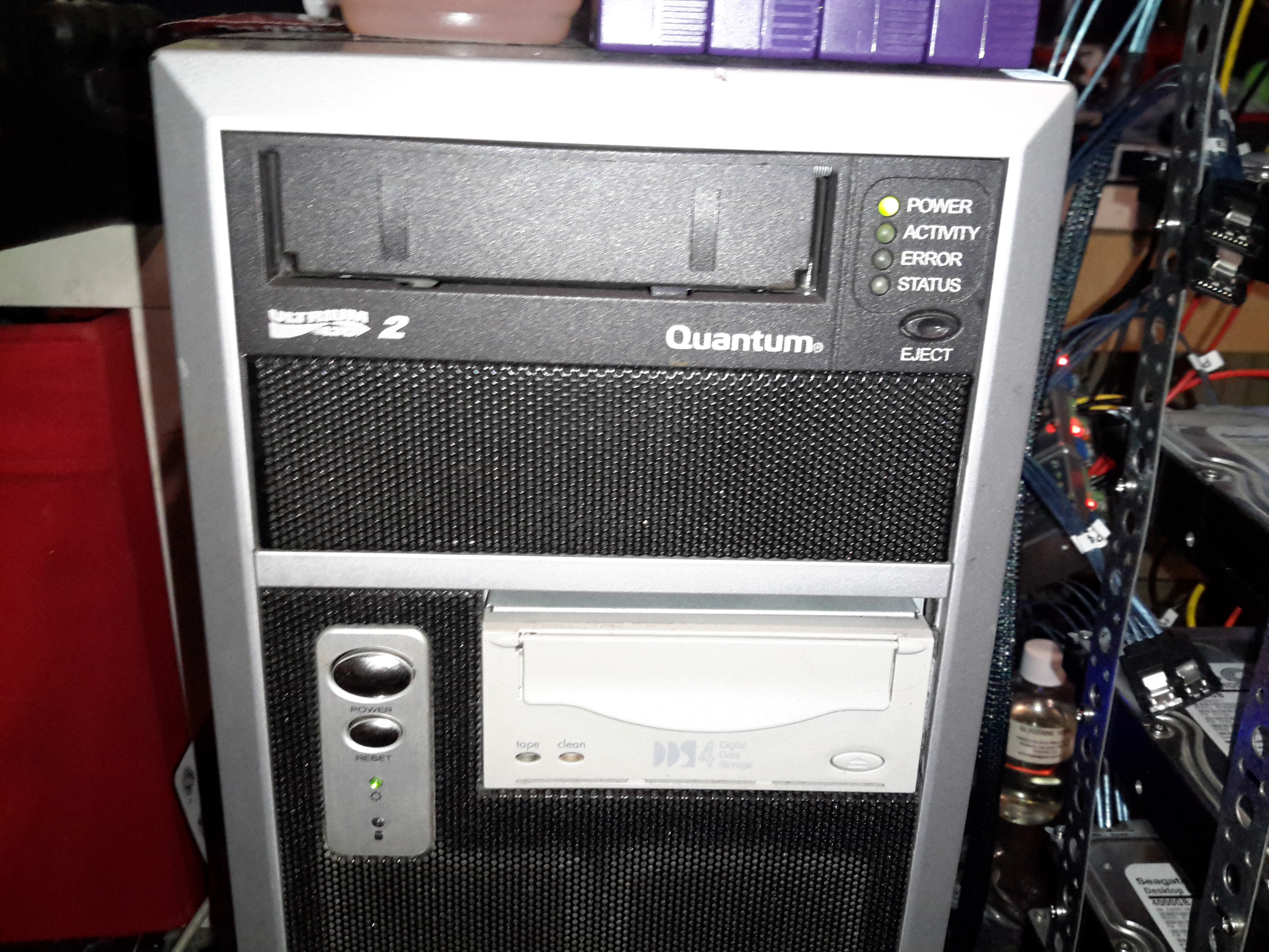
Backup Drives
The tape drives are LTO2 300/600GB for large file backup & DDS4 20/40GB DAT for smaller stuff. These were had cheap on eBay, with a load of tapes. Newer LTO drives aren’t an option due to cost.
The main disk array is currently built as 9 disks in service with a single hot spare, in case of disk failure, this gives a total size after parity of 28TB:
/dev/md0:
        Version : 1.2
  Creation Time : Wed Mar 11 16:01:01 2015
     Raid Level : raid6
     Array Size : 27348211520 (26081.29 GiB 28004.57 GB)
  Used Dev Size : 3906887360 (3725.90 GiB 4000.65 GB)
   Raid Devices : 9
  Total Devices : 10
    Persistence : Superblock is persistent

  Intent Bitmap : Internal

    Update Time : Mon Nov 14 14:28:59 2016
          State : active
 Active Devices : 9
Working Devices : 10
 Failed Devices : 0
  Spare Devices : 1

         Layout : left-symmetric
     Chunk Size : 64K

           Name : Main-PC:0
           UUID : 266632b8:2a8a3dd3:33ce0366:0b35fad9
         Events : 773938

    Number   Major   Minor   RaidDevice State
       0       8       48        0      active sync   /dev/sdd
       1       8       32        1      active sync   /dev/sdc
       9       8       96        2      active sync   /dev/sdg
      10       8      112        3      active sync   /dev/sdh
      11       8       16        4      active sync   /dev/sdb
       5       8      176        5      active sync   /dev/sdl
       6       8      144        6      active sync   /dev/sdj
       7       8      160        7      active sync   /dev/sdk
       8       8      128        8      active sync   /dev/sdi

      12       8        0        -      spare   /dev/sda
The disks used are Seagate ST4000DM000 Desktop HDDs, which at this point have ~15K hours on them, and show no signs of impending failure.
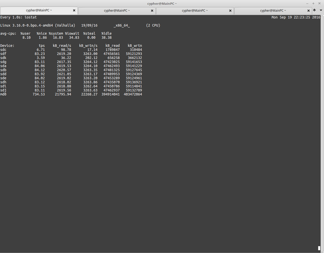
USB3 Speeds
Here’s a screenshot with the disk array fully loaded running over USB3. The aggregate speed on the md0 device is only 21795KB/s. Extremely slow indeed.
This card is structured similarly to the external USB3 bays – a PCI Express bridge glues 4 Marvell 9215 4-port SATA controllers into a single x8 card. Bus contention may become an issue with all 16 ports used, but as far with 9 active devices, the performance increase is impressive. Adding another disk to the active array would certainly give everything a workout, as rebuilding with an extra disk will hammer both read from the existing disks & will write to the new.
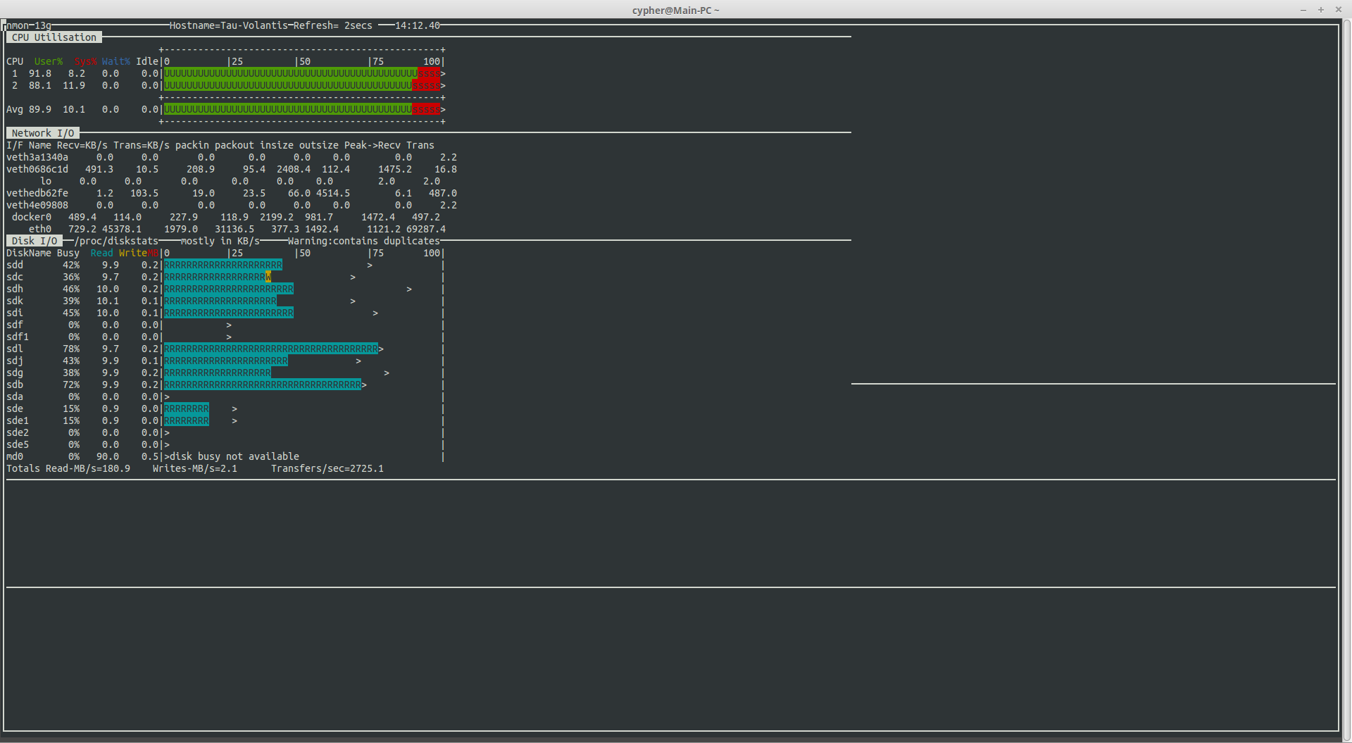
HBA Speeds
With all disks on the new controller, I’m sustaining read speeds of 180MB/s. (Pulling data off over the network). Write speeds are always going to be pretty pathetic with RAID6, as parity calculations have to be done. With Linux MD, this is done by the host CPU, which is currently a Core2Duo E7500 at 2.96GHz, with this setup, I get 40-60MB/s writes to the array with large files.
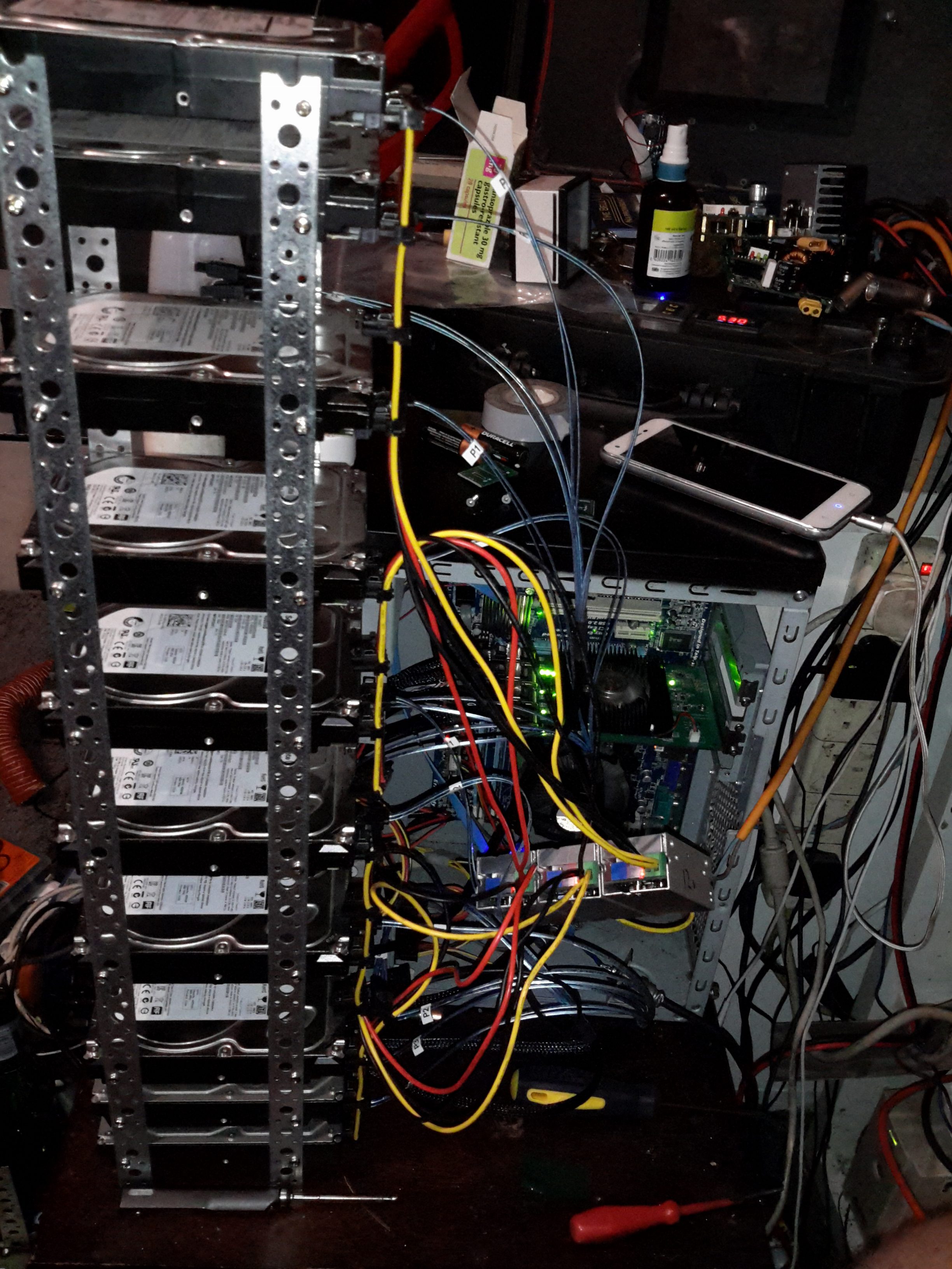
Disk Array
Since I don’t have a suitable case with built in drive bays, (again, they’re expensive), I’ve had to improvise with some steel strip to hold the disks in a stack. 3 DC-DC converters provides the regulated 12v & 5v for the disks from the main unregulated 12v system supply. Both the host system & the disks run from my central battery-backed 12v system, which acts like a large UPS for this.
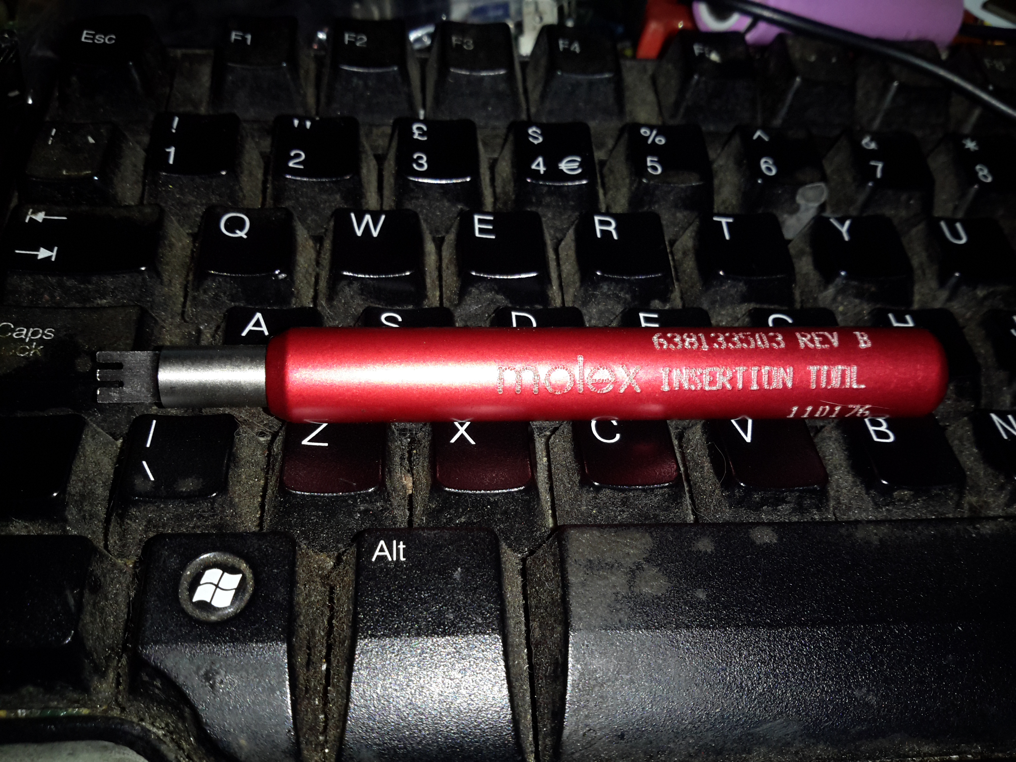
The SATA power splitters were custom made, the connectors are Molex 67926-0001 IDC SATA power connectors, with 18AWG cable to provide the power to 4 disks in a string.
IDT Insertion Tool
These require the use of a special tool if you value your sanity, which is a bit on the expensive side at £25+VAT, but doing it without is very difficult. You get a very well made tool for the price though, the handle is anodised aluminium & the tool head itself is a 300 series stainless steel.
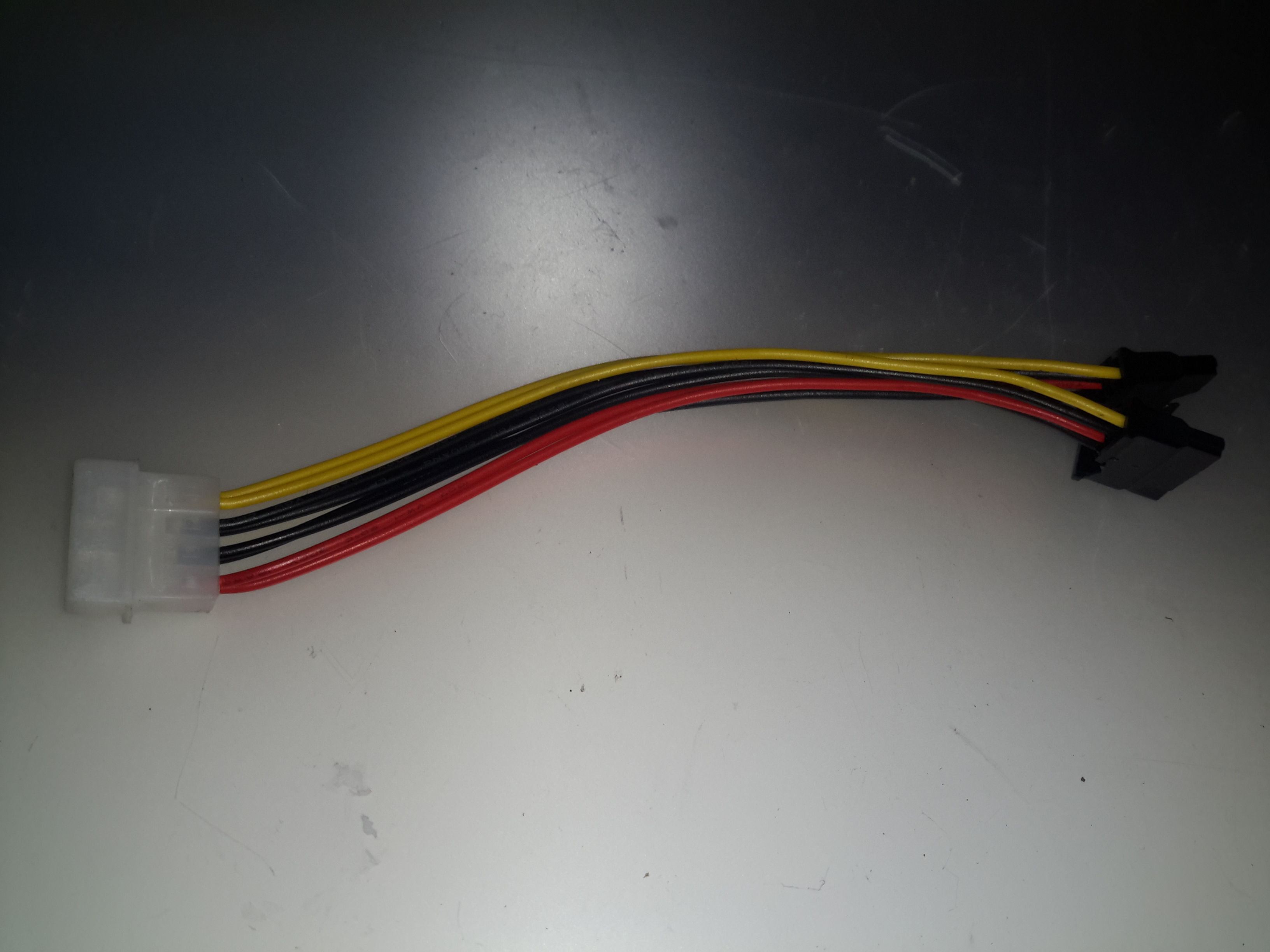
To do some upgrades to my NAS, I needed some SATA power adaptors, to split the PSU out to the planned 16 disk drives. eBay has these for very little money, however there’s a good reason for them being cheap.
Wire Marking
The marking on the wire tells me it’s 18AWG, which should be good for 9.5A at an absolute maximum. However these adaptors are extremely light.
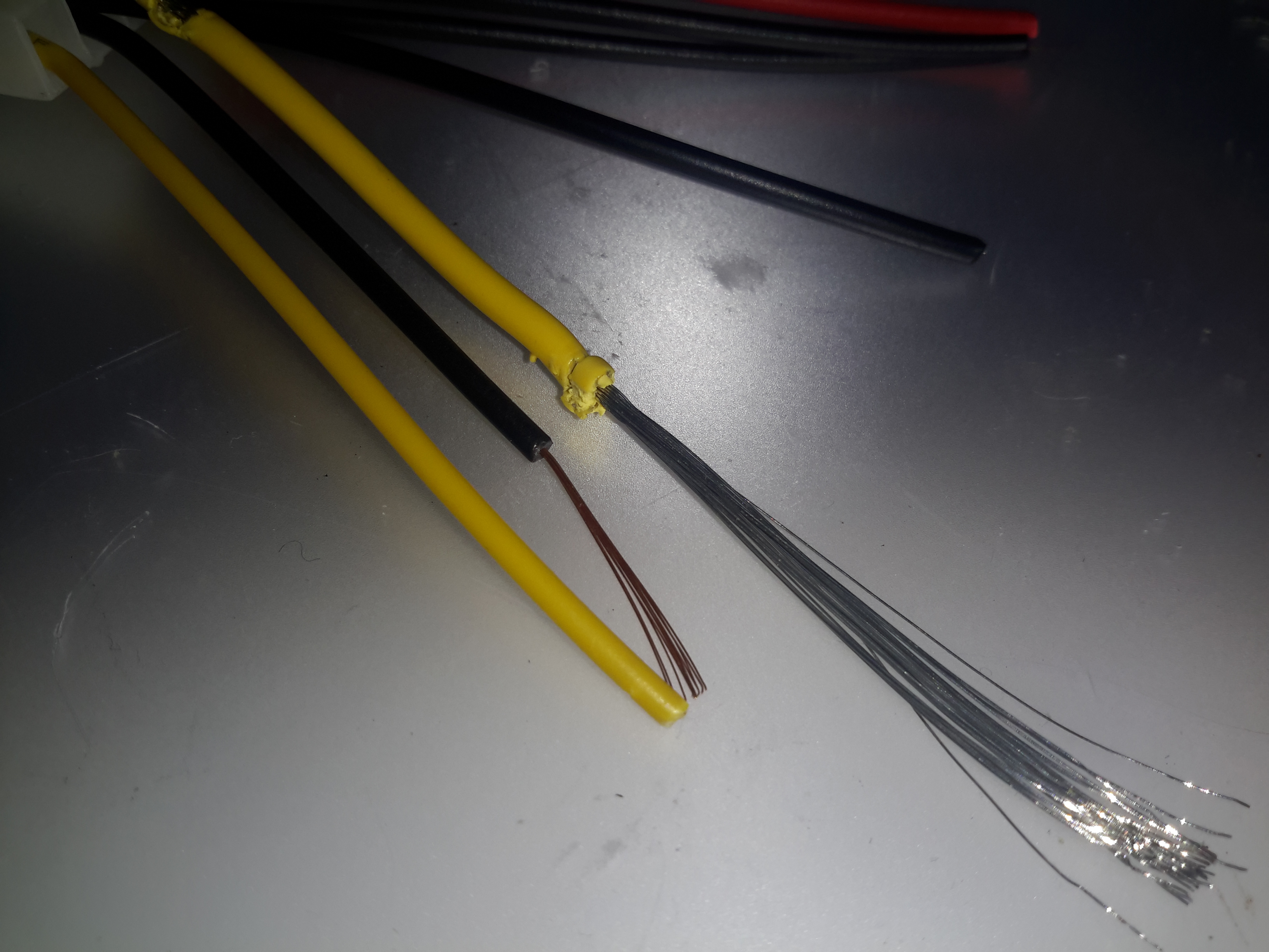
Wire Comparison
Here’s the cheapo eBay wire compared to proper 18AWG wire. The cores in the eBay adaptor are tiny, I’d guess about 24AWG, only good for about 3A. As disk drives pull about 2A from the +12v rail on startup to spin the platters up to speed, this thin wire is going to cause quite the volt drop & possibly prevent the disk from operating correctly.
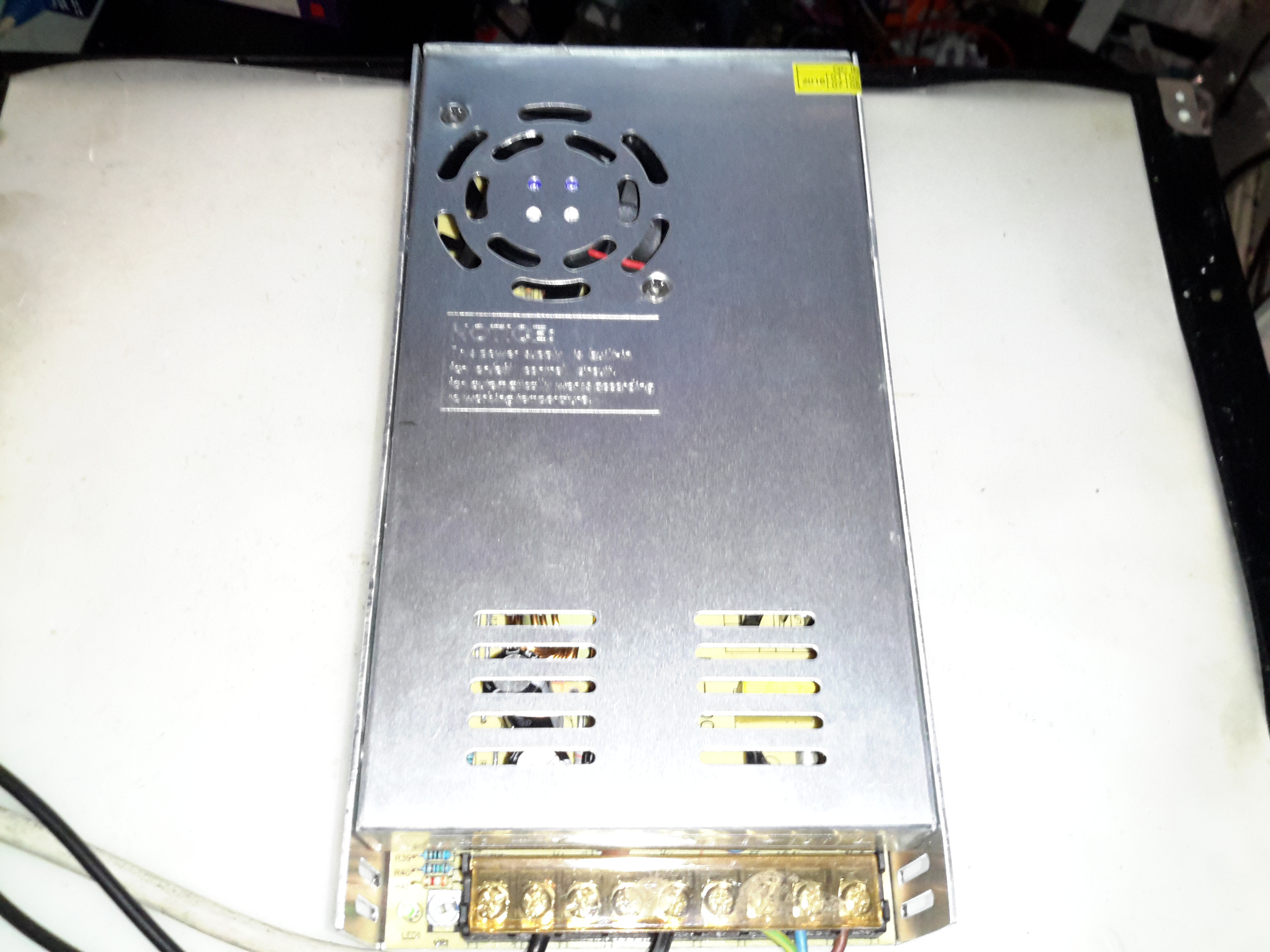
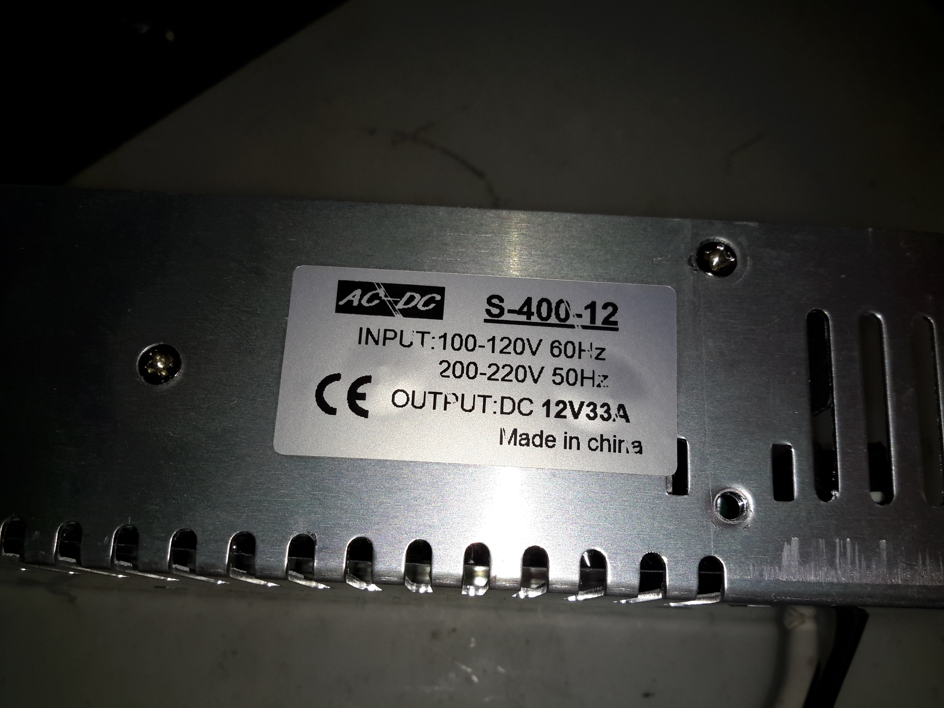
Here’s a cheap PSU from the treasure trove of junk that is eBay, rated at a rather beefy 400W of output at 12v – 33A! These industrial-type PSUs from name brands like TDK-Lambda or Puls are usually rather expensive, so I was interested to find out how much of a punishment these cheap Chinese versions will take before grenading. In my case this PSU is to be pushed into float charging a large lead acid battery bank, which when in a discharged state will try to pull as many amps from the charger as can be provided.
Rating Label
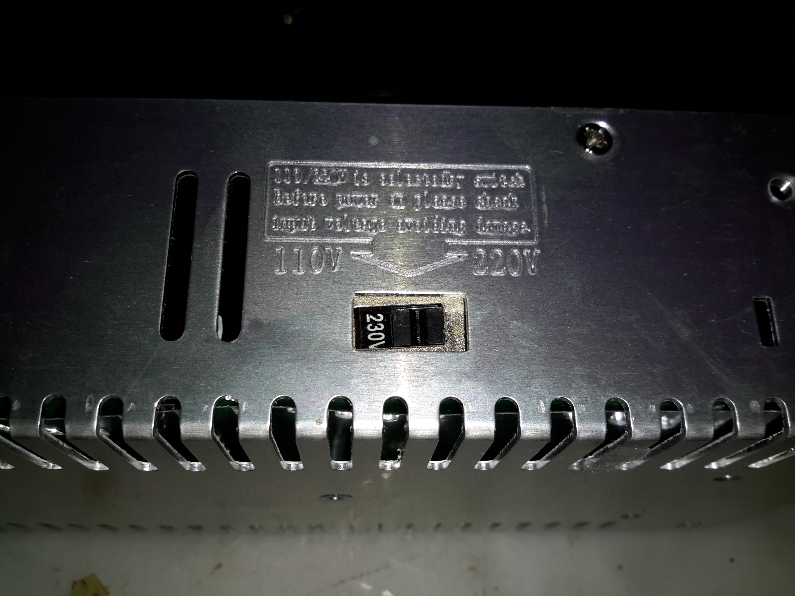
These PSUs are universal input, voltage adjustable by a switch on the other side of the PSU, below. The output voltage is also trimmable from the factory, an important thing for battery charging, as the output voltage needs to be sustained at 13.8v rather than the flat 12v from the factory.
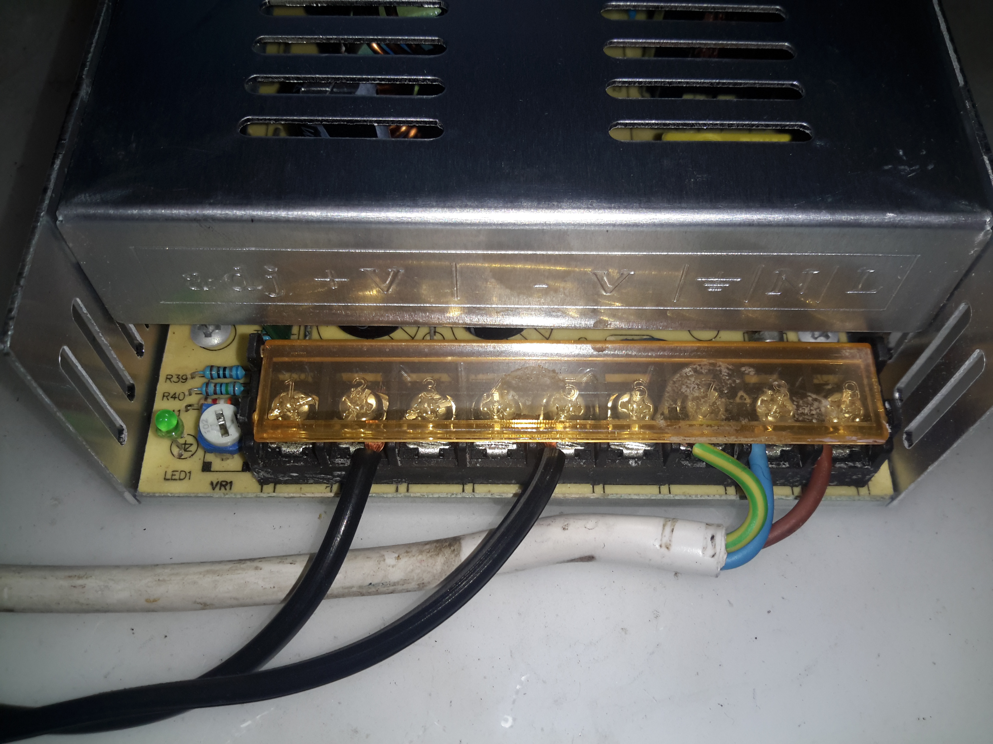
Input Voltage SelectorMain Terminal Block
Mains connections & the low voltage outputs are on beefy screw terminals. The output voltage adjustment potentiometer & output indicator LED are on the left side.
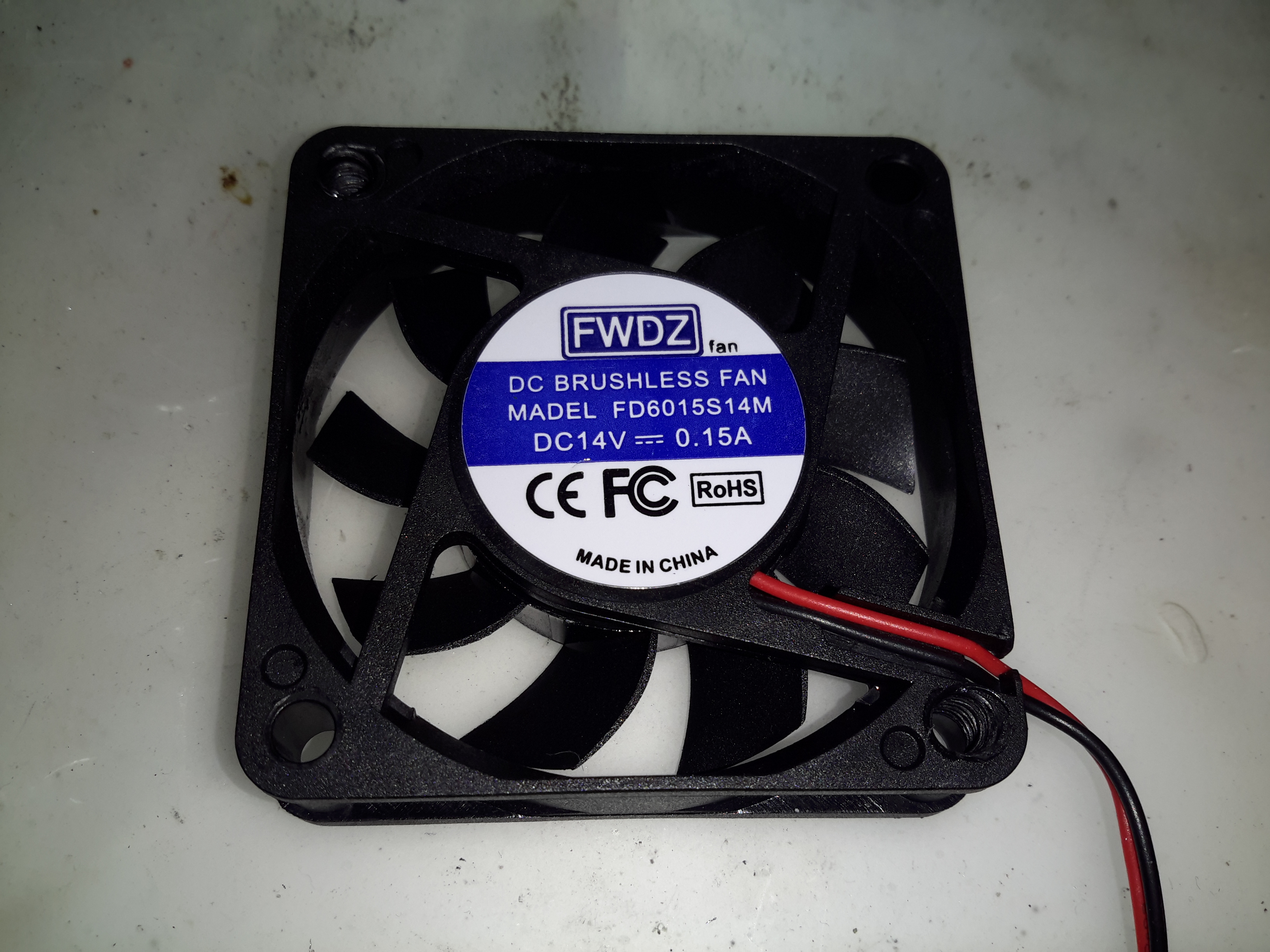
Cooling Fan
The cooling fan for the unit, which pulls air through the casing instead of blowing into the casing is a cheap sleeve bearing 60mm fan. No surprises here. I’ll probably replace this with a high-quality ball-bearing fan, to save the PSU from inevitable fan failure & overheating.
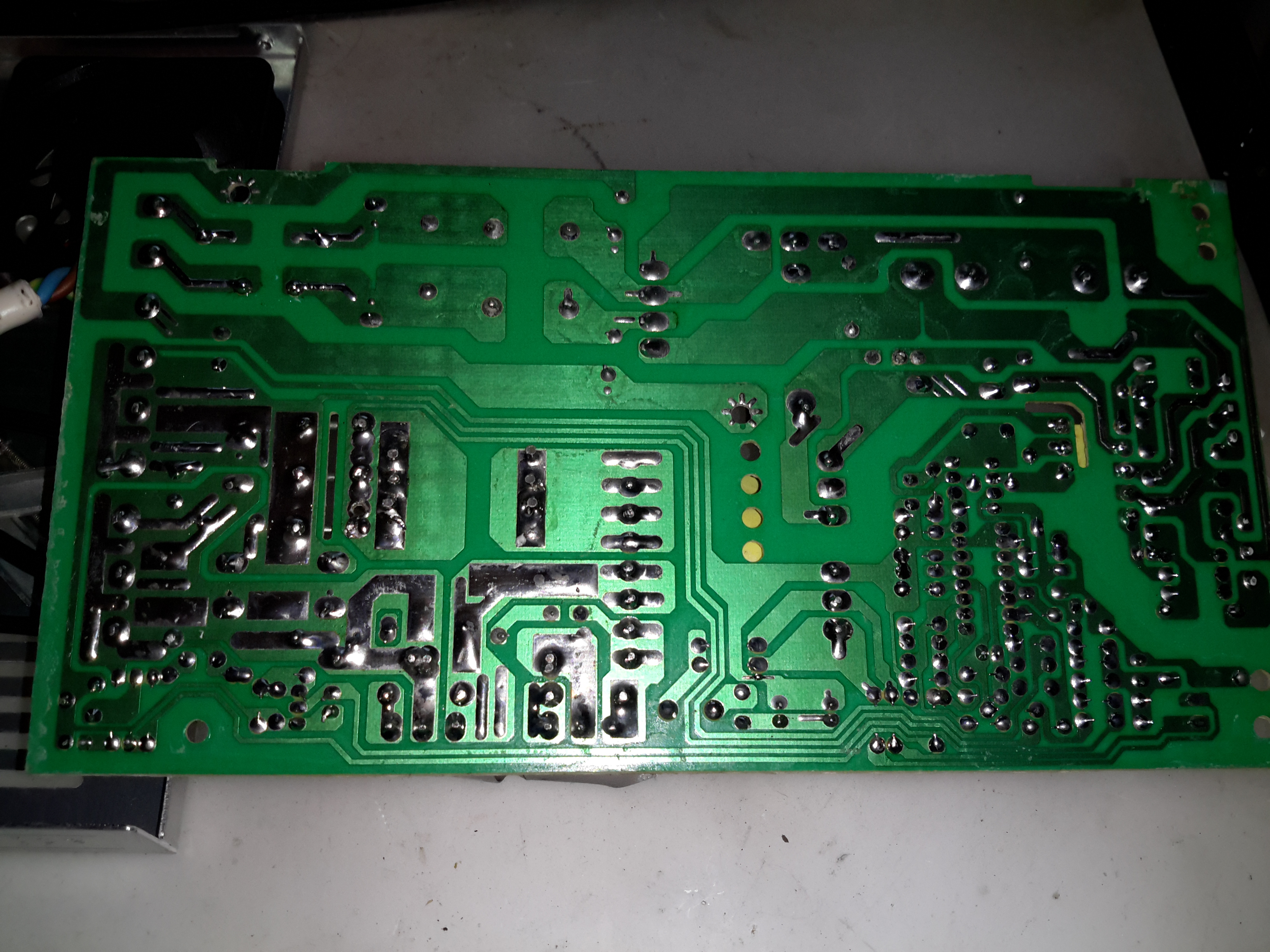
PCB Bottom
The PCB tracks are generously laid out on the high current output side, but there are some primary/secondary clearance issues in a couple of places. Lindsay Wilson over at Imajeenyus.com did a pretty thorough work-up on the fineries of these PSUs, so I’ll leave most of the in-depth stuff via a linky. There’s also a modification of this PSU for a wider voltage range, which I haven’t done in this case as the existing adjustment is plenty wide enough for battery charging duty.
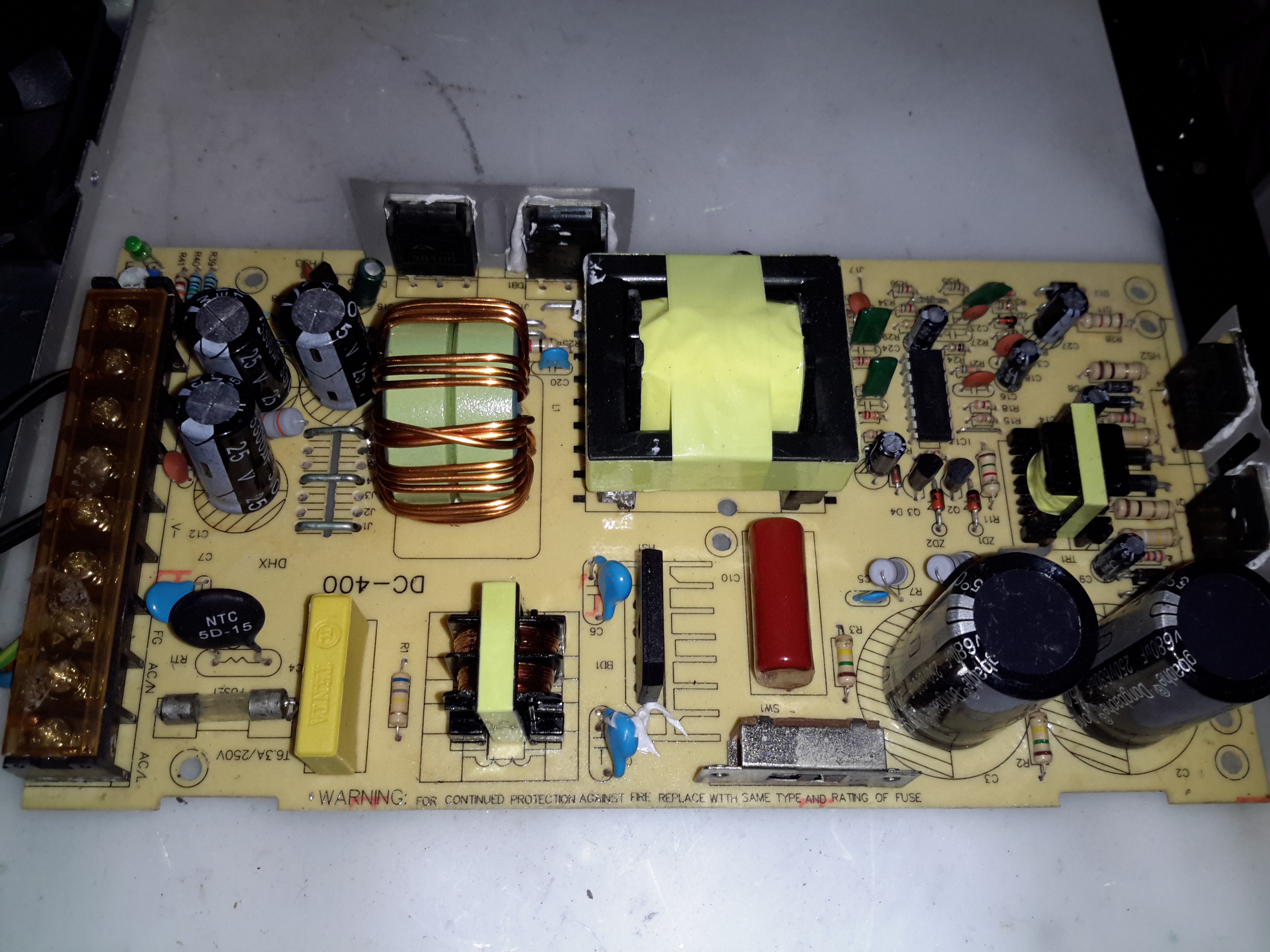
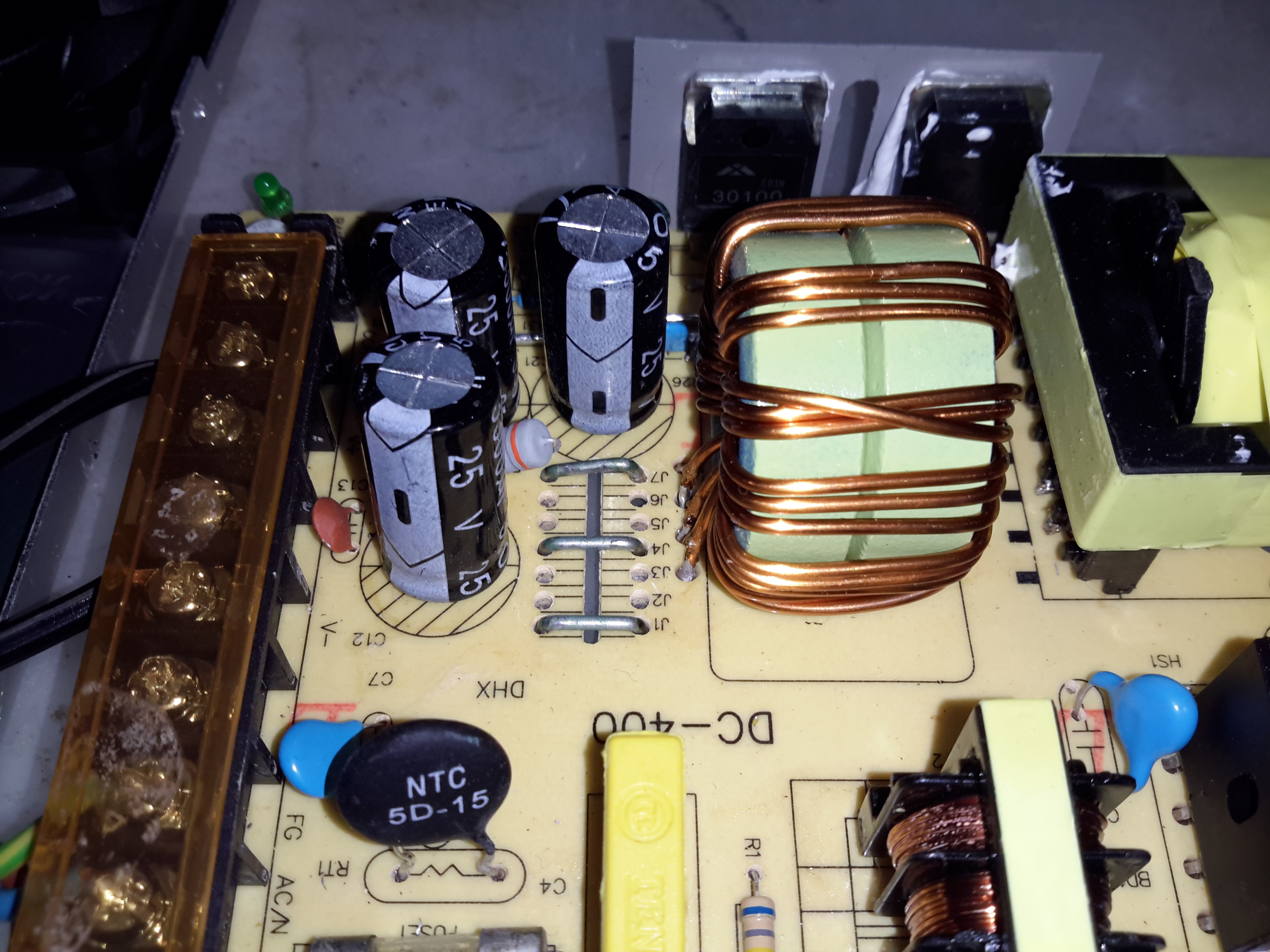
Bare PCB
The PCB is laid out in the usual fashion for these PSUs, with the power path taking a U-route across the board. Mains input is lower left, with some filtering. Main diode bridge in the centre, with the voltage selection switch & then the main filter caps. Power is then switched into the transformer by the pair of large transistors on the right before being rectified & smoothed on the top left.
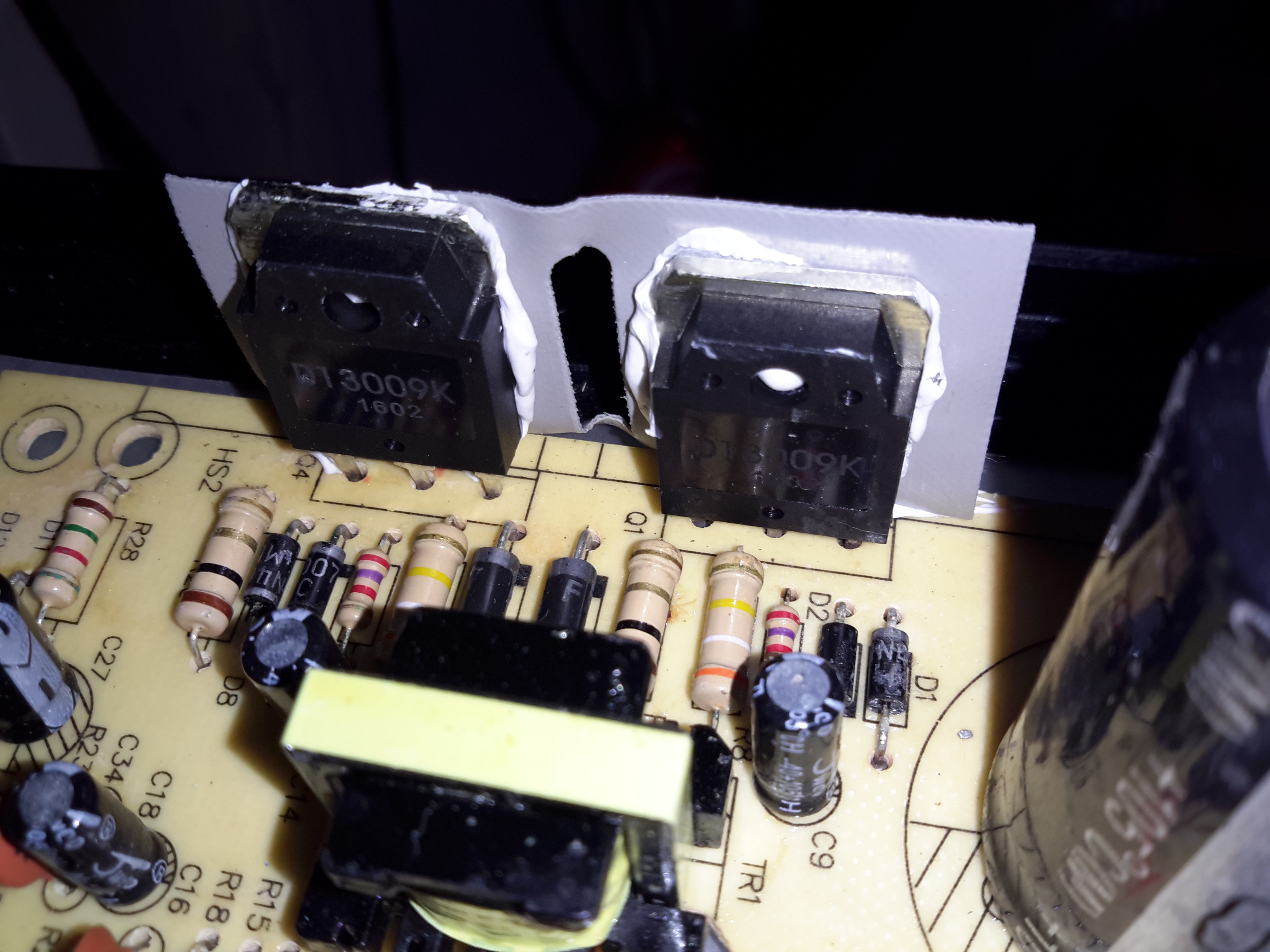
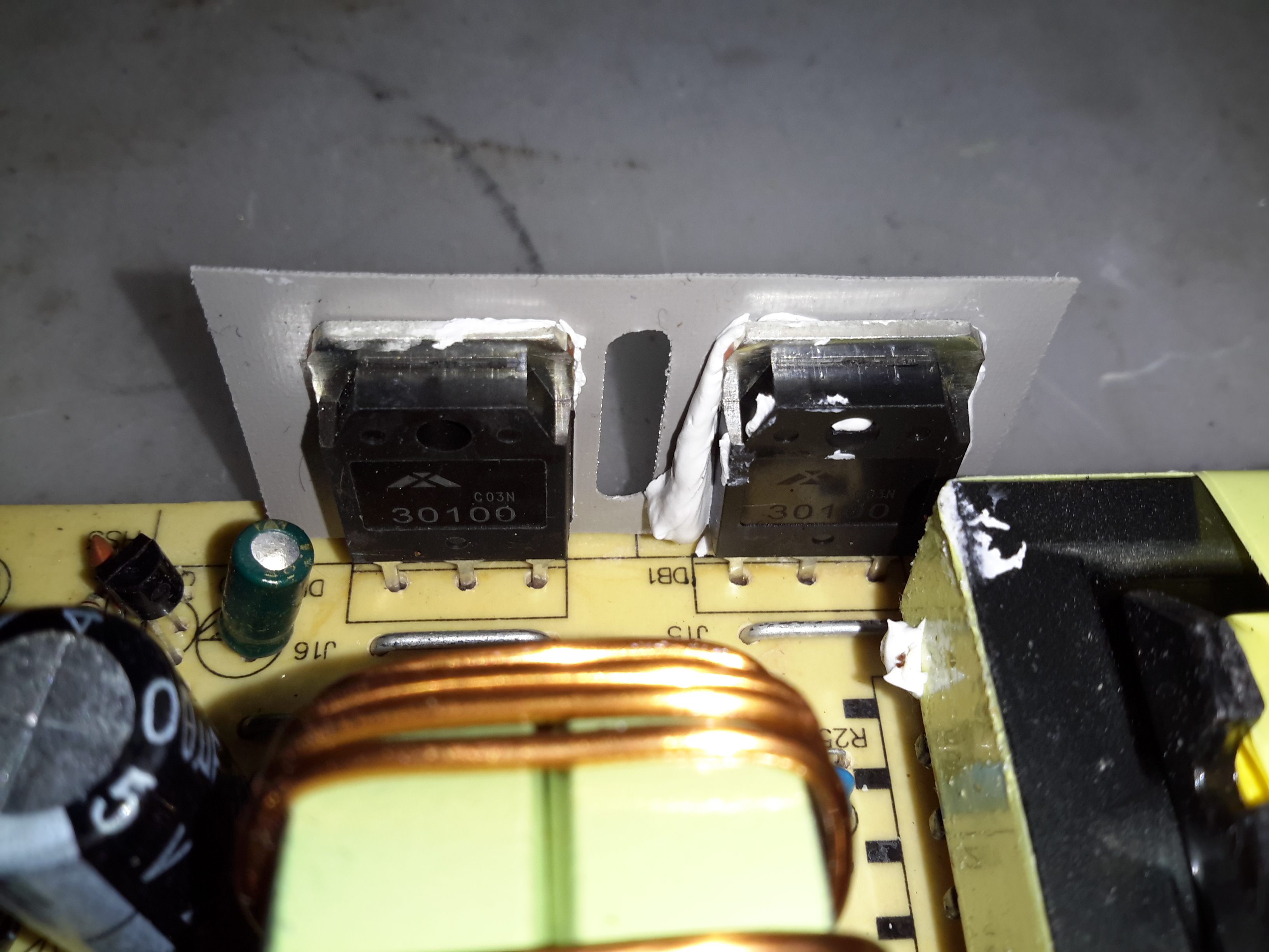
Main Switching Transistors
The pair of main switching devices are mounted to the casing with thermal compound & an insulating pad. To bridge the gap there’s a chunk of aluminium which also provides some extra heatsinking.
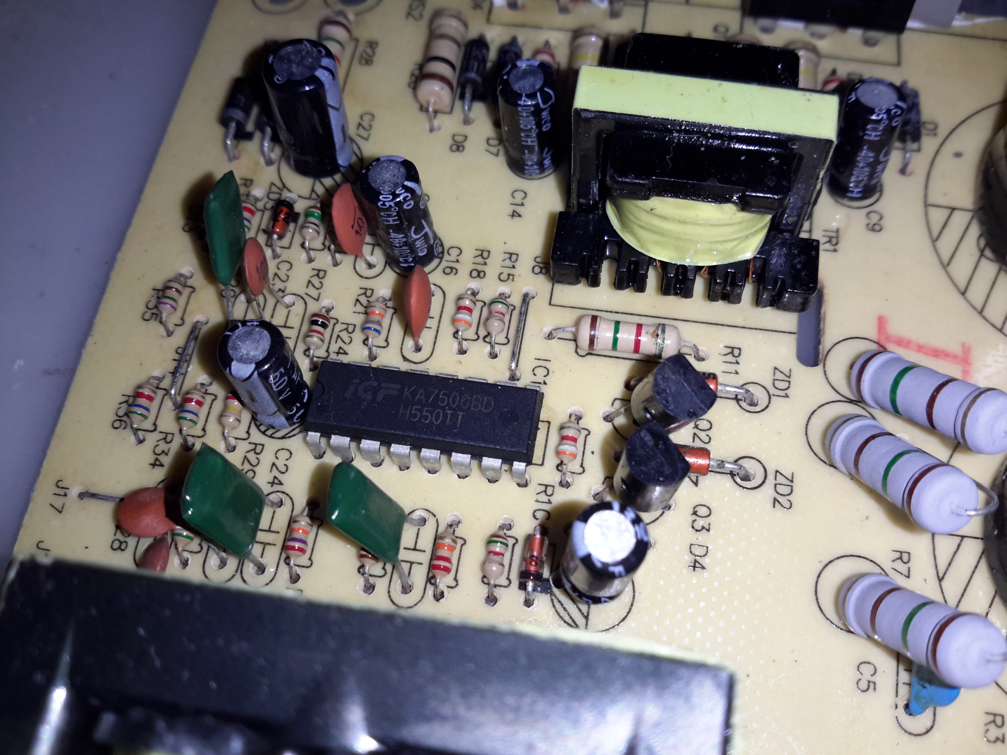
SMPS Drive IC & Base Drive Transformer
The PSU is controlled by a jelly-bean TL494 PWM controller IC. No active PFC in this cheap supply so the power factor is going to be very poor indeed.
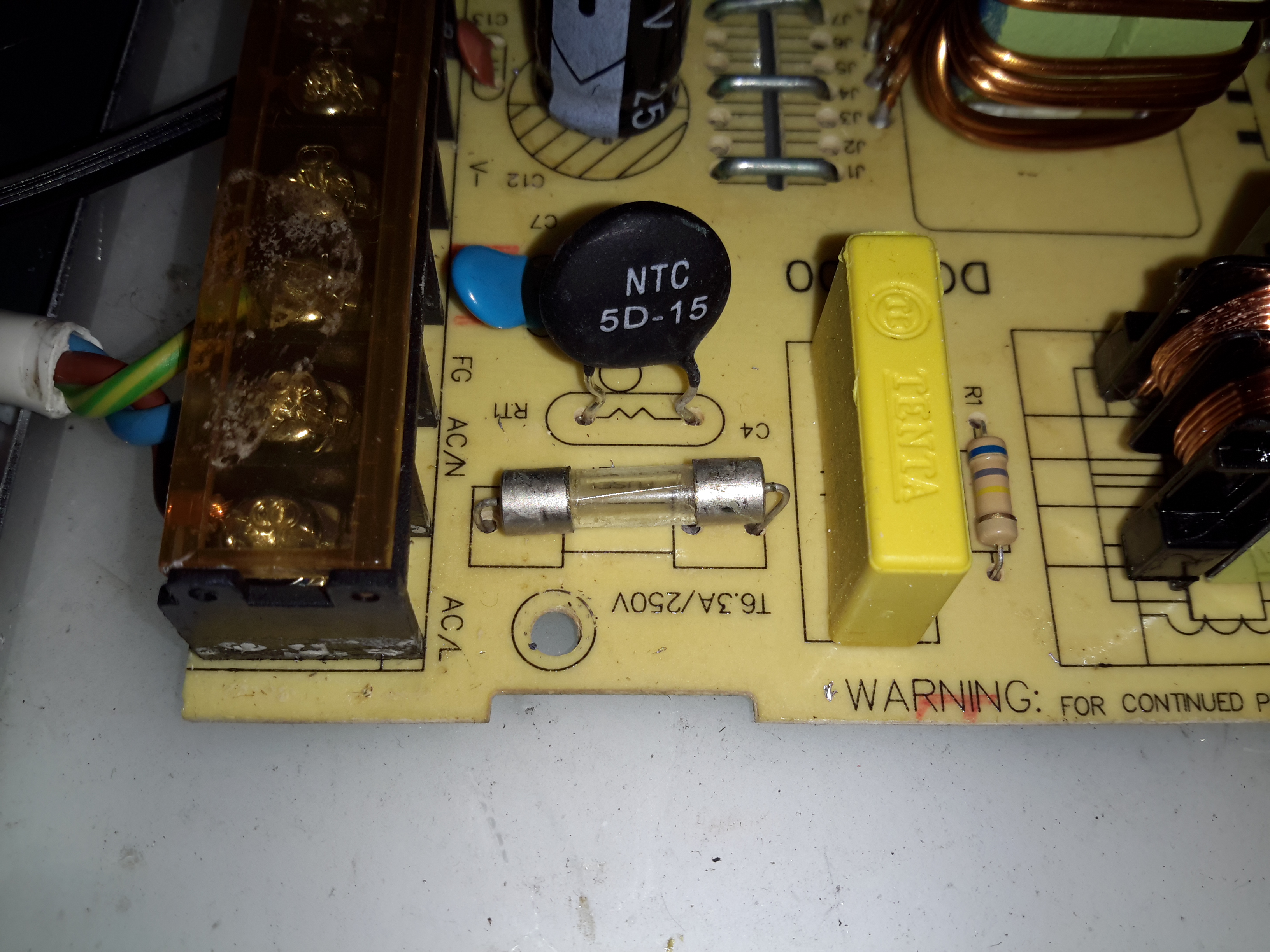
Input Protection
Input protection & filtering is rather simple with the usual fuse, MOV filter capacitor & common mode choke.
Main Output Rectifiers
Beefy 30A dual diodes on the DC output side, mounted in the same fashion as the main switching transistors.
Output Current Shunt
Current measurement is done by these large wire links in the current path, selectable for different models with different output ratings.
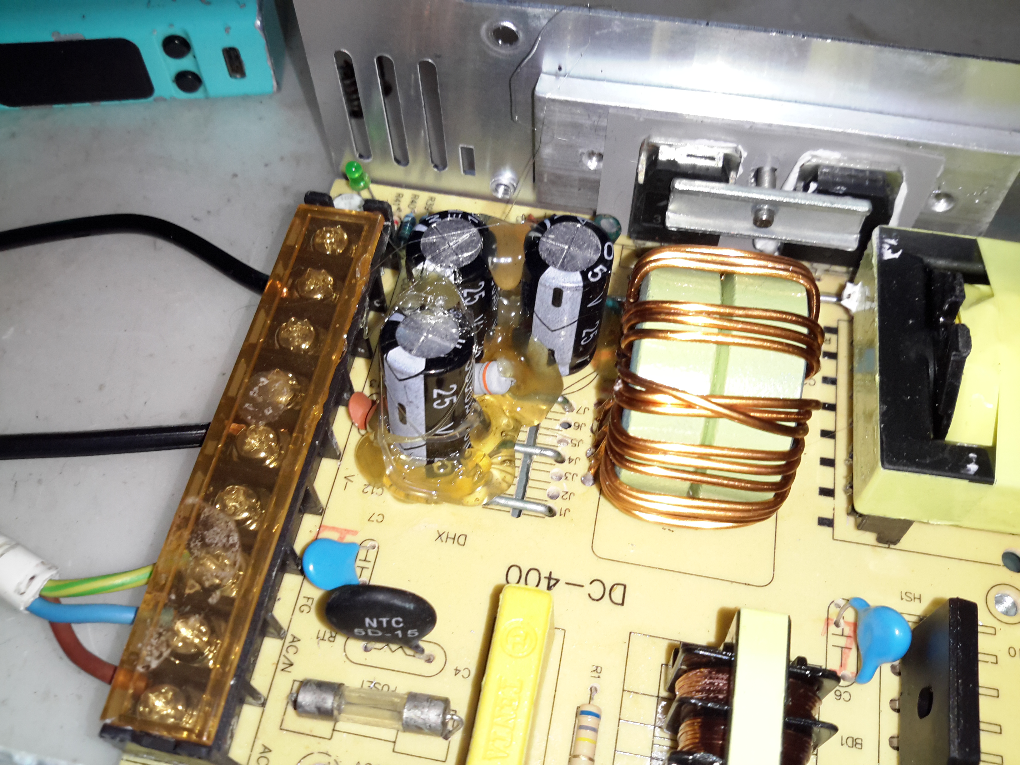
Hot Glue Support
The output capacitors were just floating around in the breeze, with one of them already having broken the solder joints in shipping! After reflowing the pads on all the capacitors some hot glue as flowed around them to stop any further movement.
This supply has now been in service for a couple of weeks at a constant 50% load, with the occasional hammering to recharge the battery bank after a power failure. at 13A the supply barely even gets warm, while at a load high enough to make 40A rated cable get uncomfortably warm (I didn’t manage to get a current reading, as my instruments don’t currently go high enough), the PSU was hot in the power semiconductor areas, but seemed to cope at full load perfectly well.
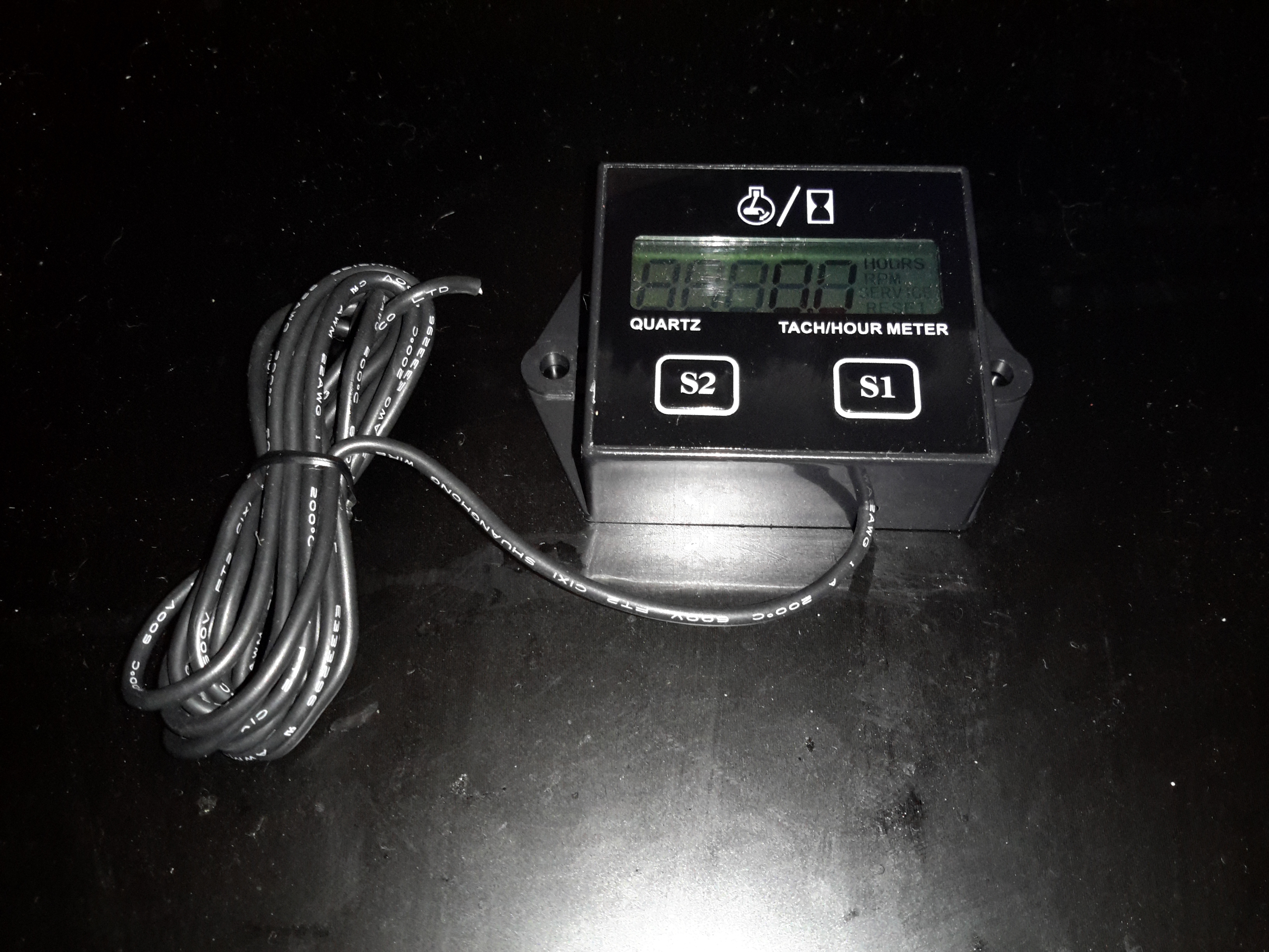
As one of my current projects involves a small petrol engine – a Honda GX35 clone, I figured an hour counter would be very handy to keep an eye on service intervals. (More to come on the engine itself later on). I found a device that would suit my needs on good old eBay.
Inductive Engine Monitor
These engine monitors are pretty cheap, at about £4. The sensing is done by a single heat-resistant silicone wire, that wraps around the HT lead to the spark plug. The unit can be set for different firing intervals via the buttons. In the case of most single-cylinder 4-stroke engines, the spark plug fires on every revolution – wasted-spark ignition. This simplifies the ignition system greatly, by not requiring the timing signal be driven from 1/2 crankshaft speed. The second “wasted” spark fires into the exhaust stroke, so has no effect.
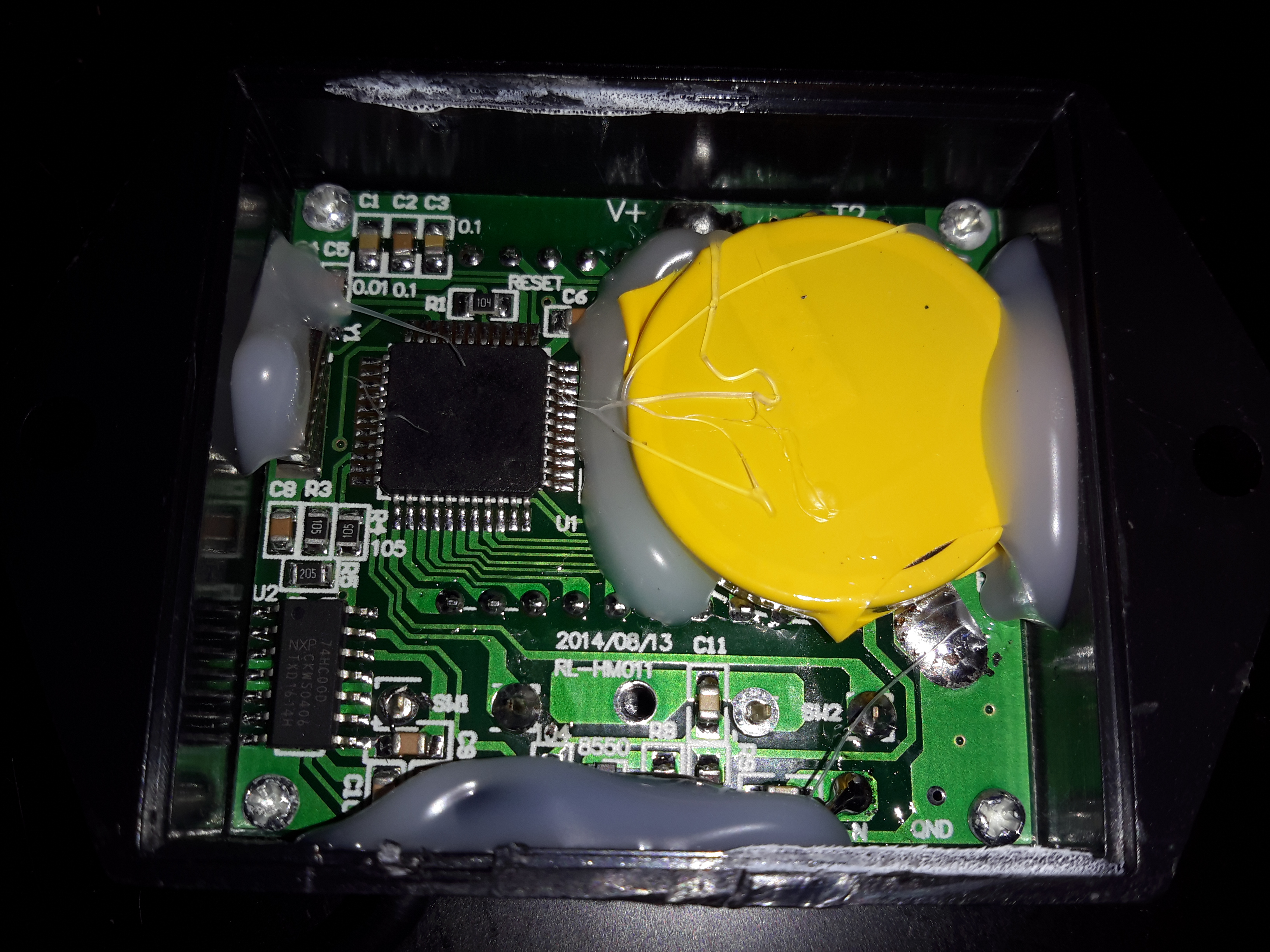
Internals
The back cover is lightly glued into place with a drop of cyanoacrylate in opposite corners, but easily pops off. The power is supplied by a soldered-in 3v Lithium cell. The main microcontroller has no number laser etched on to it at all – it appears it skipped the marking machine.
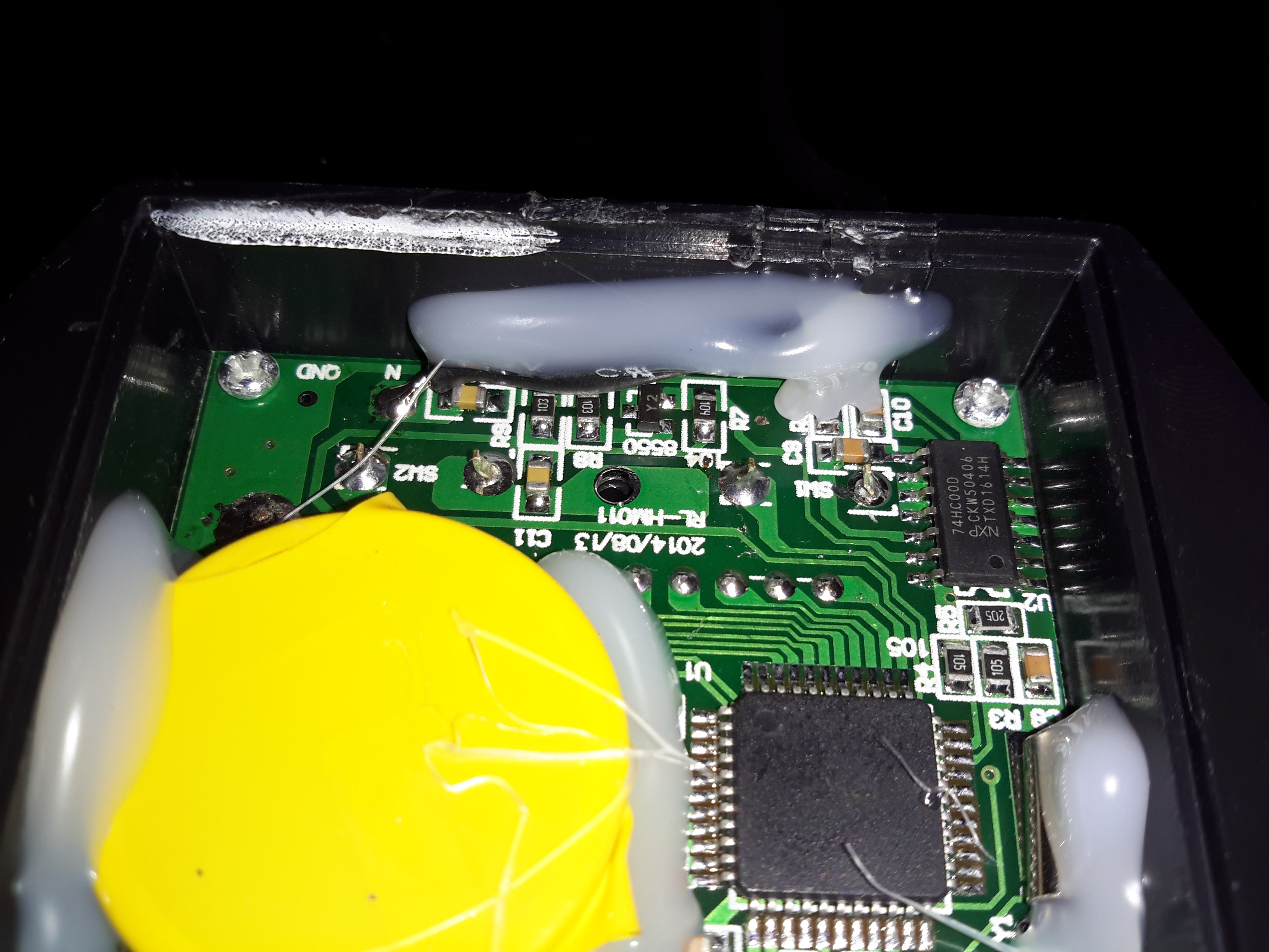
Input Filtering
The input from the sensing wire comes in through a coupling capacitor & is amplified by a transistor. It’s then fed into a 74HC00D Quad 2-Input NAND gate, before being fed into the microcontroller.
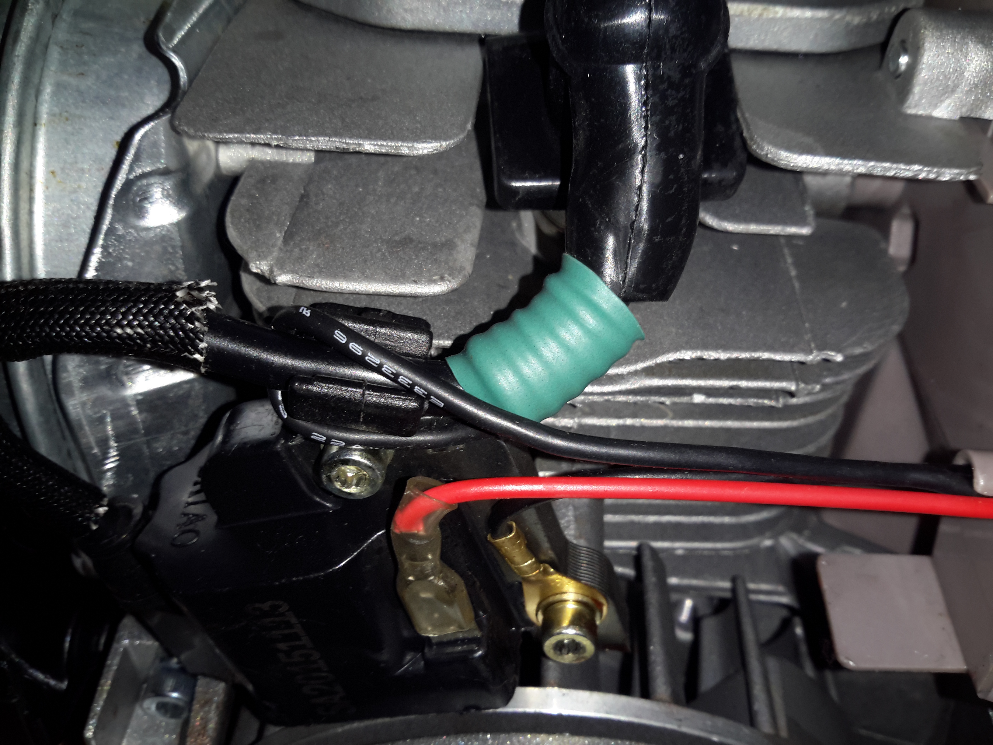
Pickup
The pickup wire is simply wound around the spark plug lead. I’ve held it in position here with some heatshrink tubing. Heat in this area shouldn’t be an issue as it’s directly in the airflow from the flywheel fan.
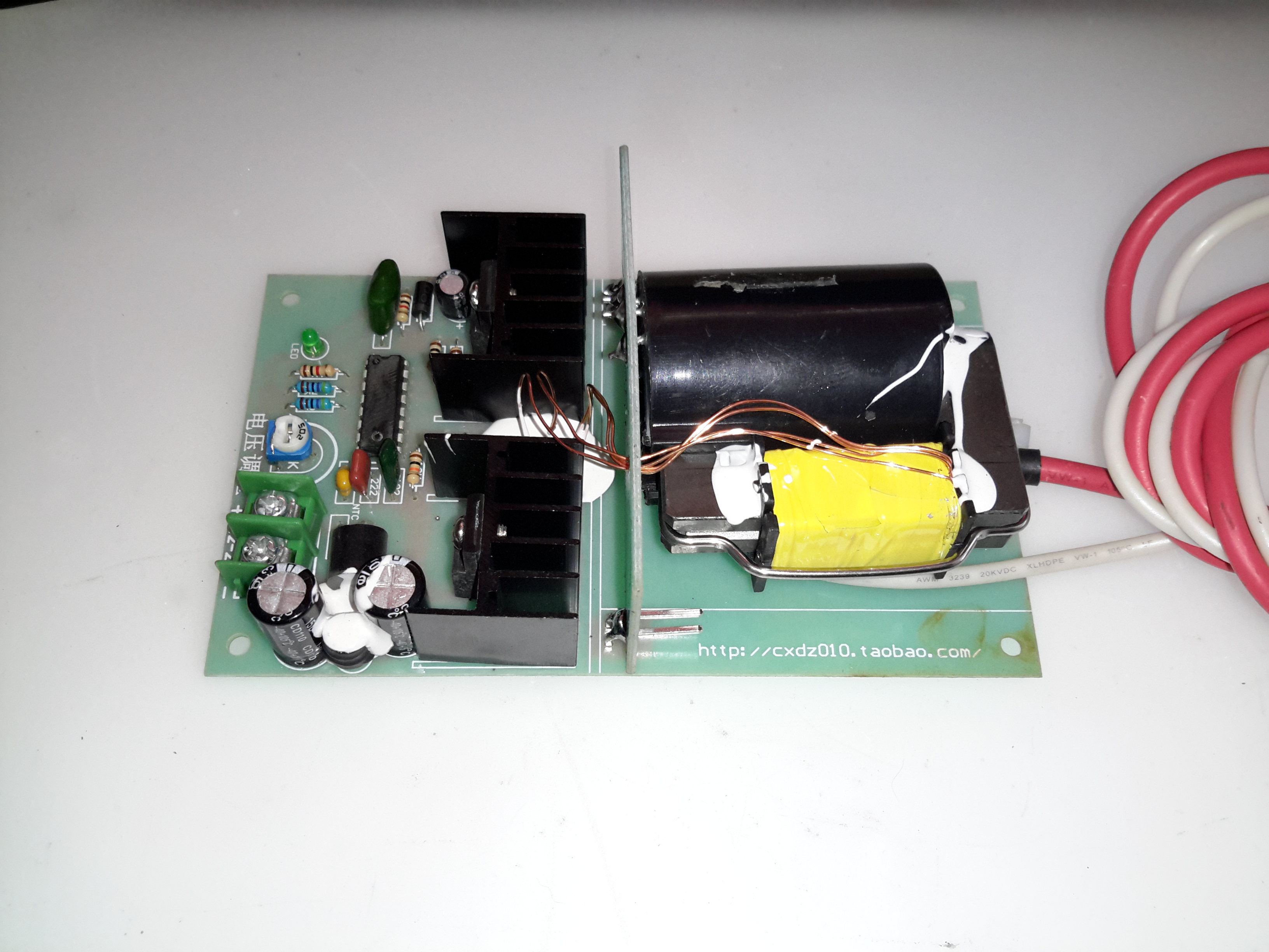
I have found myself needing some more in the way of High Voltage supplies of late, with the acquisition of the new He-Ne laser tubes, so I went trawling eBay for something that would be suitable to run these tubes. (I currently only have a single He-Ne laser PSU brick, and they’re notoriously hard to find & rather expensive).
This supply is rated at 1kV-10kV output, at 35W power level. Unfortunately this supply isn’t capable of sustaining the discharge in a large He-Ne tube, the impedance of the supply is far too high. Still, it’s useful for other experiments.
The flyback-type transformer clearly isn’t a surplus device from CRT manufacture, as there are very few pins on the bottom, and none of them connect to the primary side. The primary is separately wound on the open leg of the ferrite core.
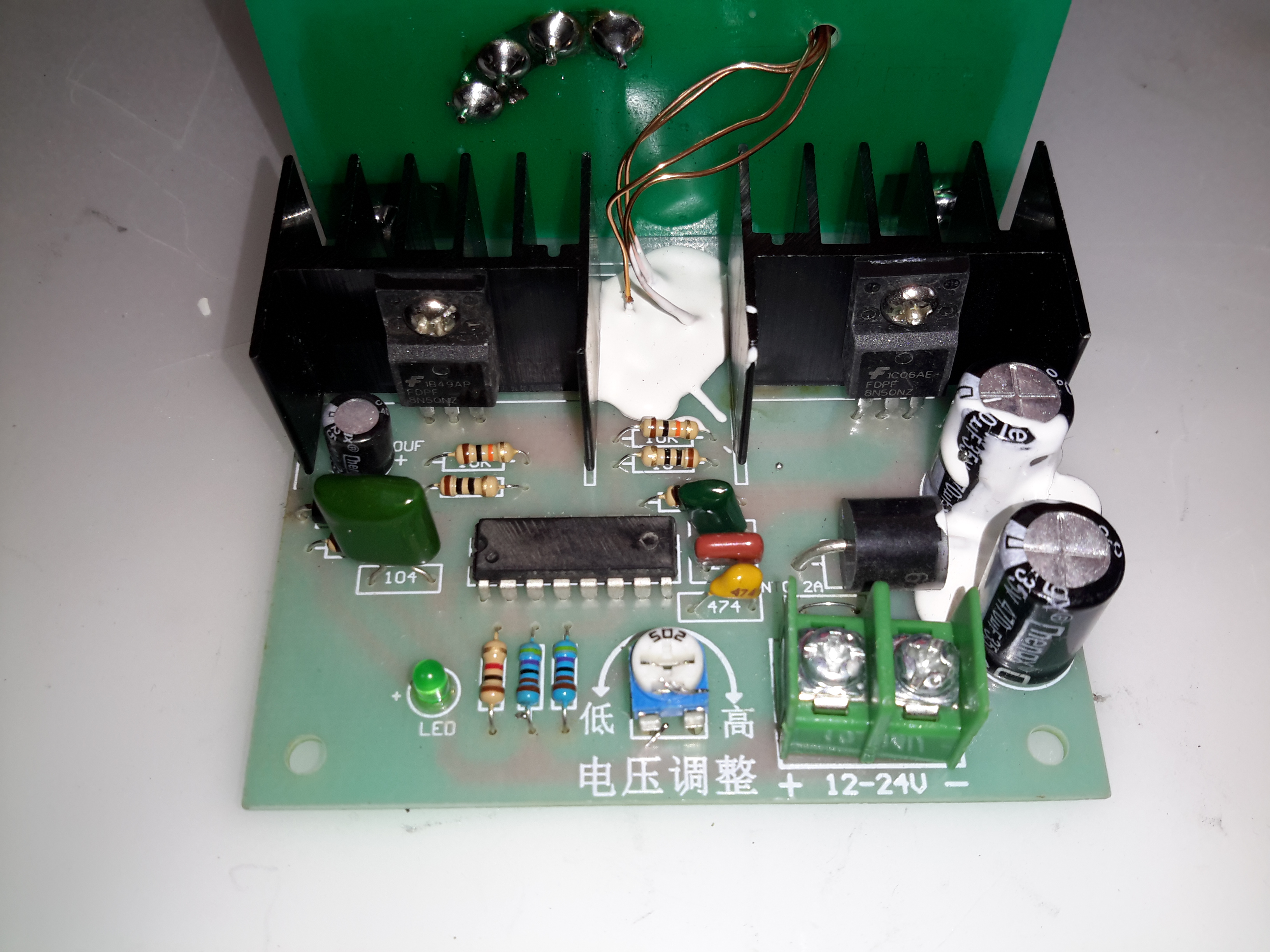
Drive Electronics
The drive electronics are pretty simple, there’s a controller IC (with the number scrubbed off – guessing it’s either a 556 dual timer or a SMPS controller), a pair of FDP8N50NZ MOSFETs driving the centre-tapped primary winding.
The drive MOSFETs aren’t anything special in this case: they’re rated at 500v 8A, 850mΩ on resistance. This high resistance does make them get rather hot even with no load on the output, so for high power use forced-air cooling from a fan would definitely be required.
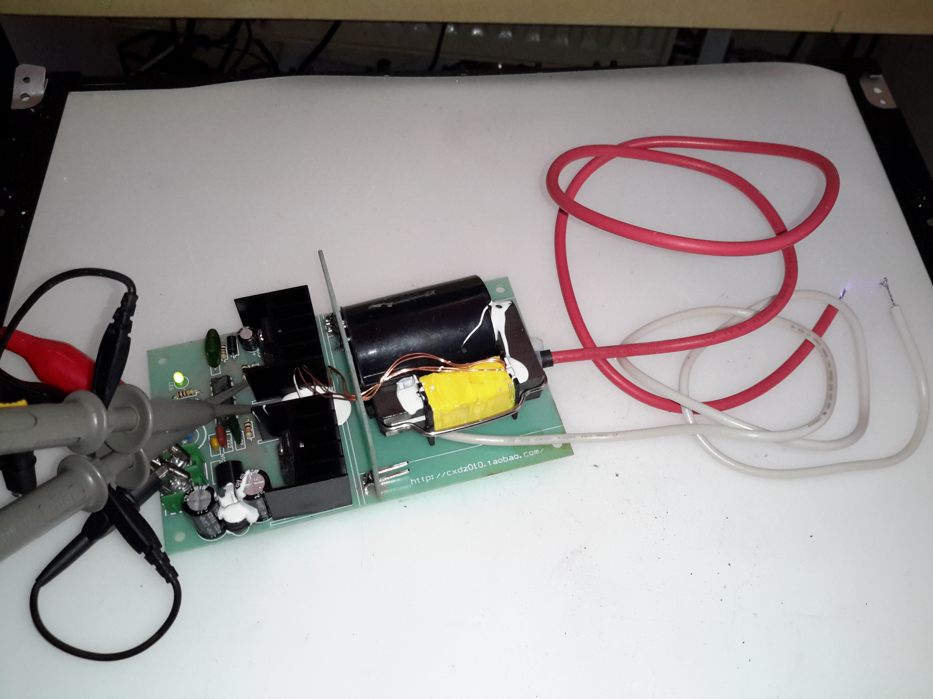
Test Setup
Here’s the supply on test, I’ve got the scope probes connected to the gate resistors of the drive MOSFETs.
Waveforms
On the scope the primary switching waveforms can be seen. The FETs operate in push-pull mode, there’s a bit of a ring on the waveform, but they’re pretty nice square waves otherwise.
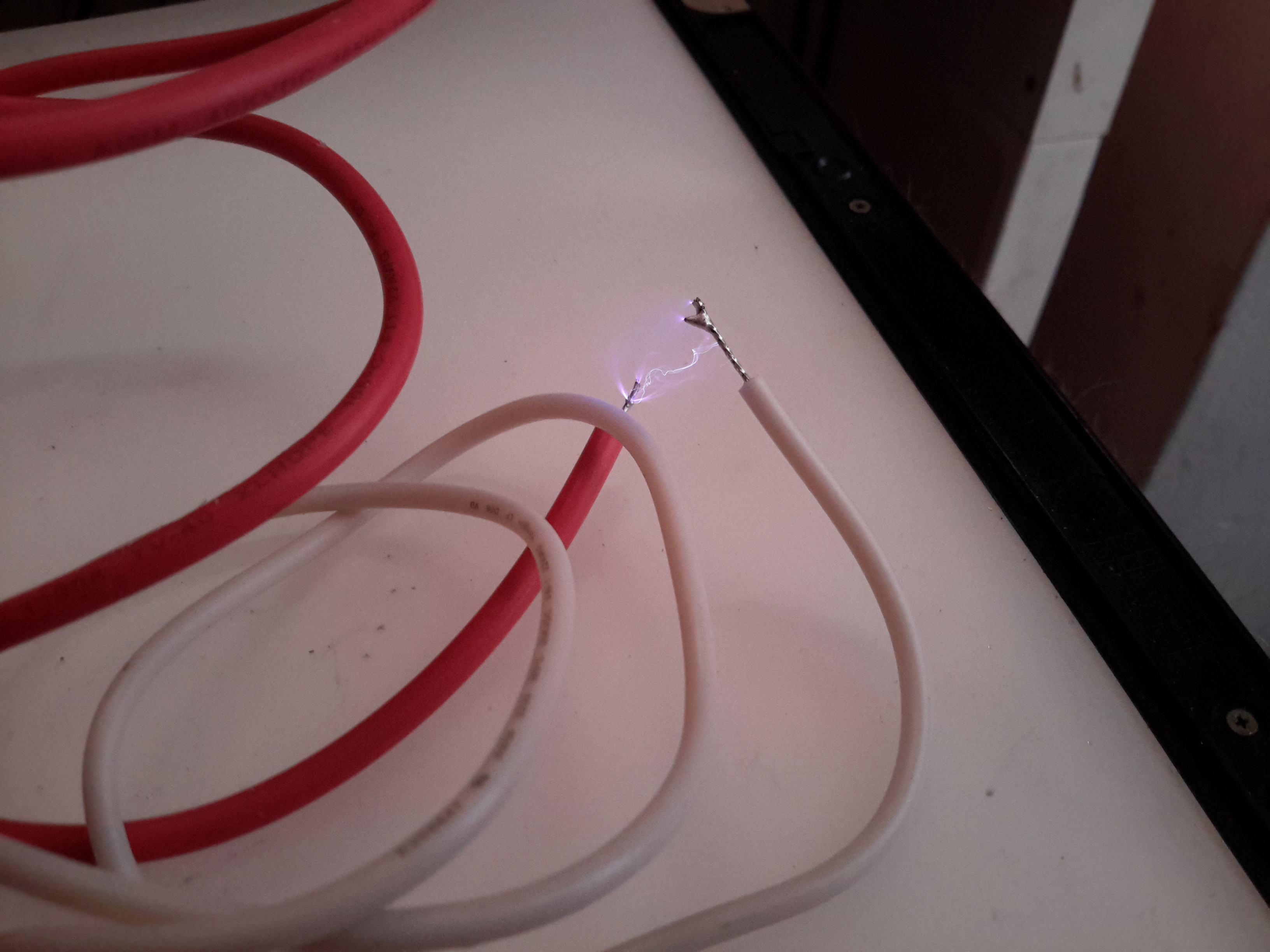
Arc
At maximum power on 12v input, about 25mm of gap is possible with an arc.
As with the previous Sony Watchman hack, injecting a composite video signal into this one is just as easy. I desoldered both the VIF/SIF IC & the digital tuner control (the tuner controller was still injecting it’s indicator into the video circuitry with the IF IC disconnected).
Composite video is on pin 18 of the Video IF IC, with the audio on Pin 13.
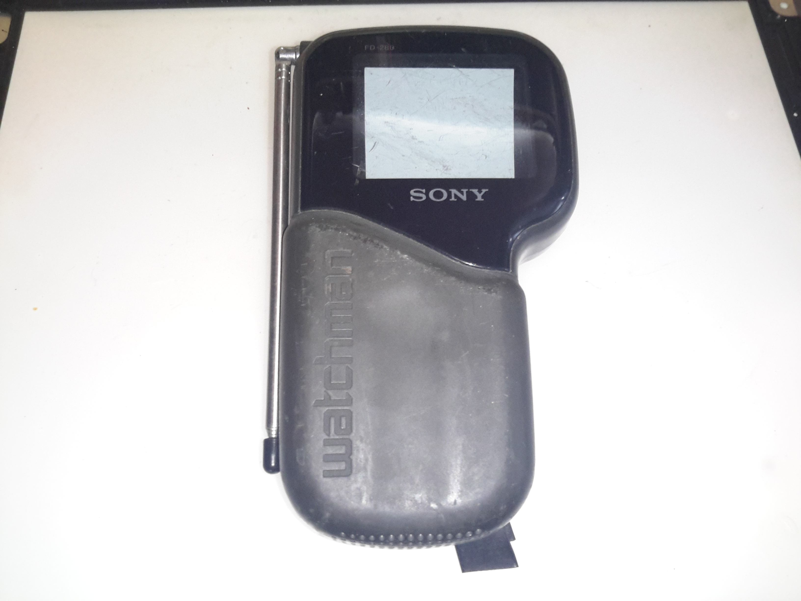
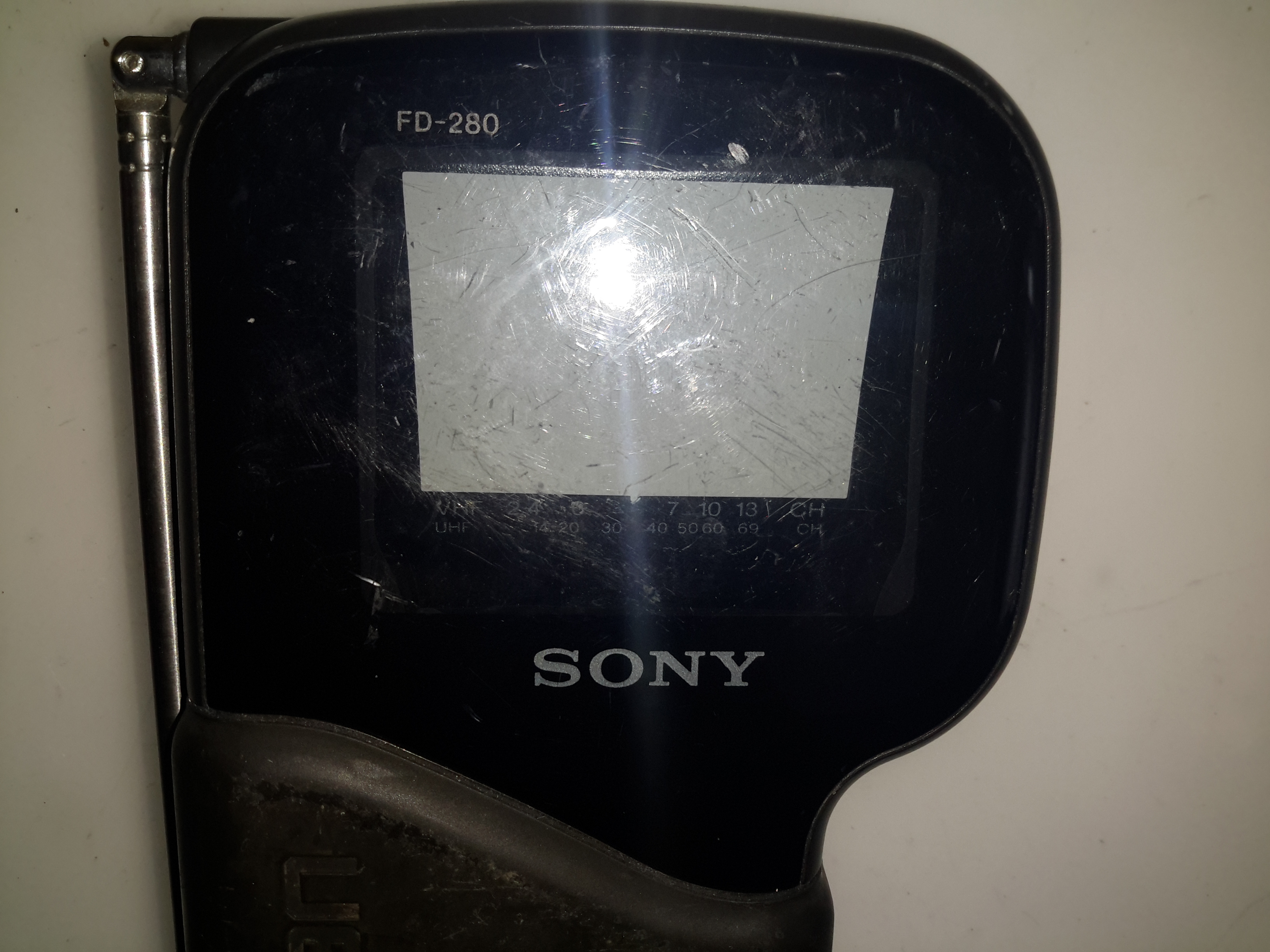
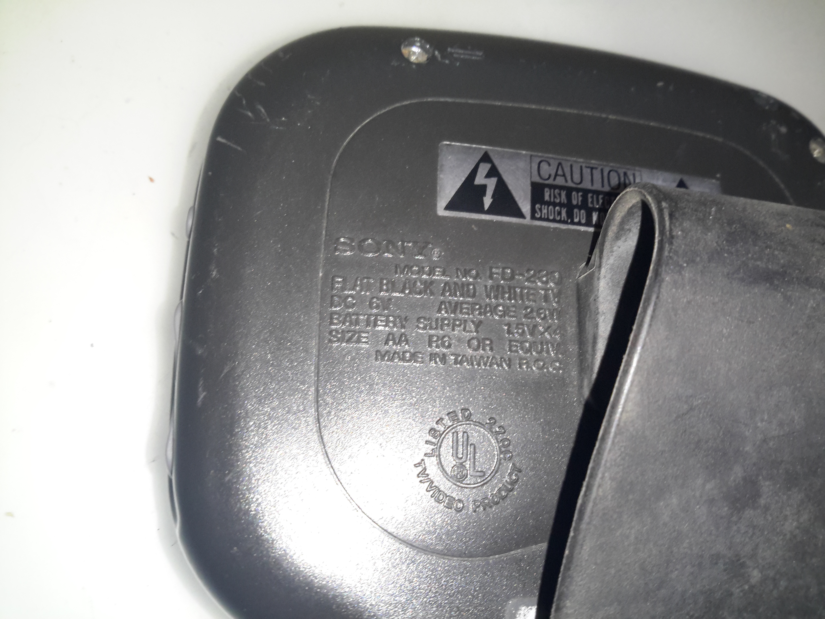
Here’s another Sony Flat CRT TV, the FD0280. This one was apparently the last to use CRT technology, later devices were LCD based. This one certainly doesn’t feel as well made as the last one, with no metal parts at all in the frame, just moulded plastic.
CRT Screen
Being a later model, this one has a much larger screen.
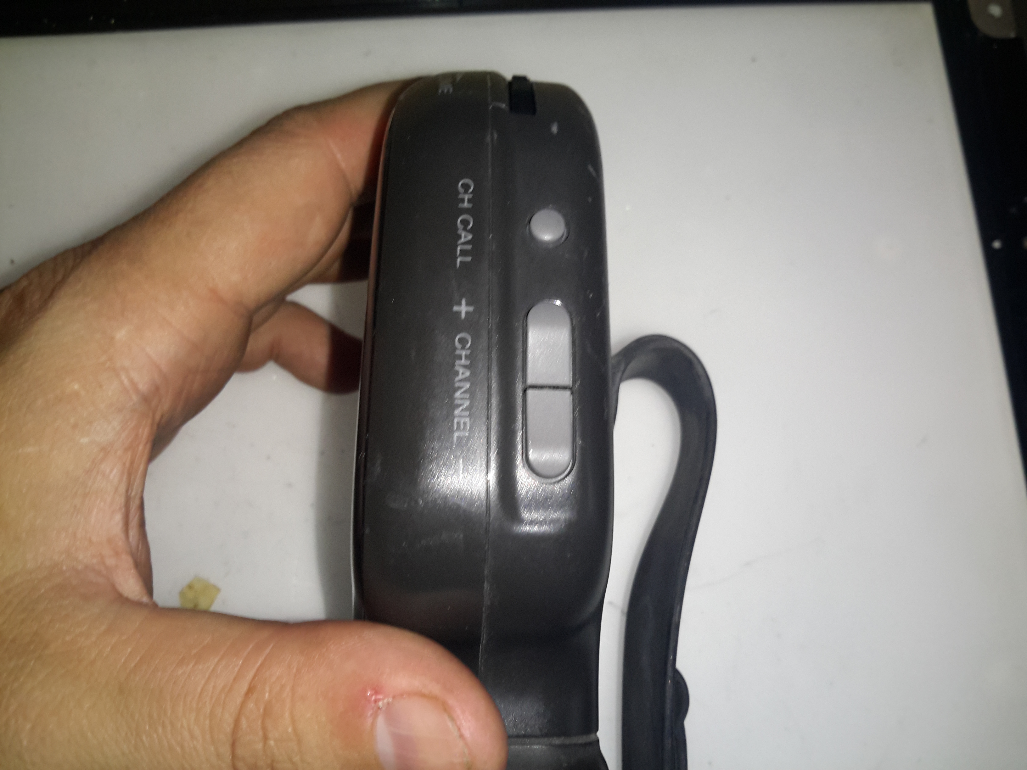
Autotuning
Instead of the manual tuner of the last Watchman, this one has automatic tuning control, to find the local stations.
Spec Label
The spec puts the power consumption a little higher than the older TV, this isn’t surprising as the CRT screen is bigger & will require higher voltages on the electrodes.
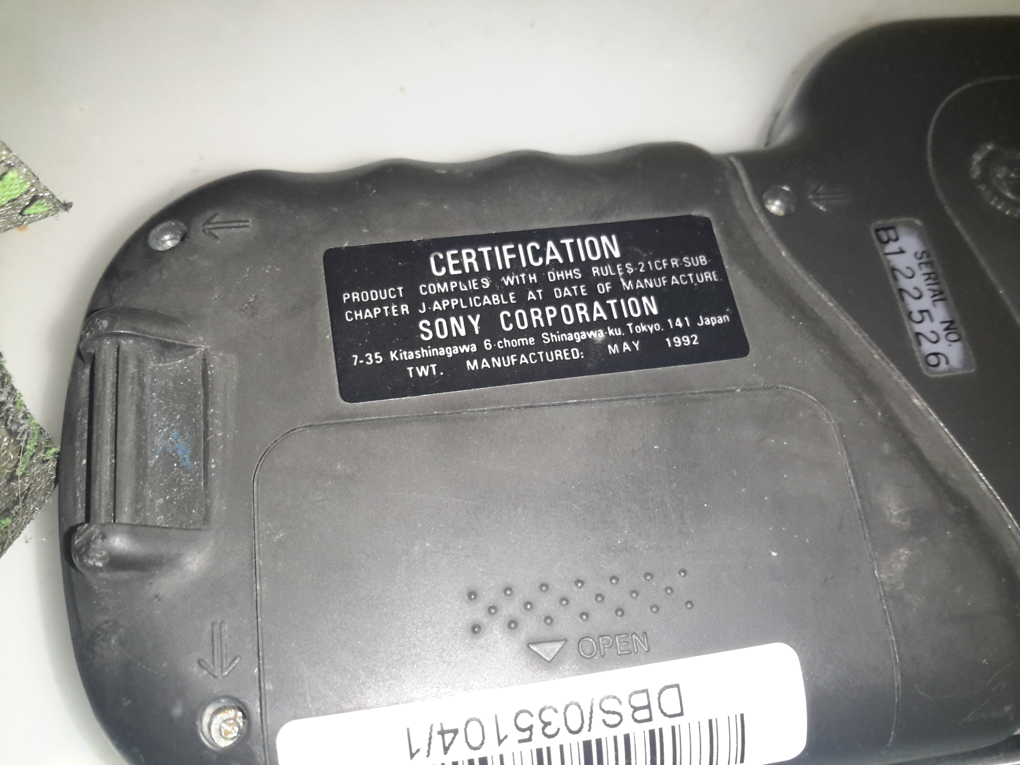
Certification Label
The certification label dates this model to May 1992.
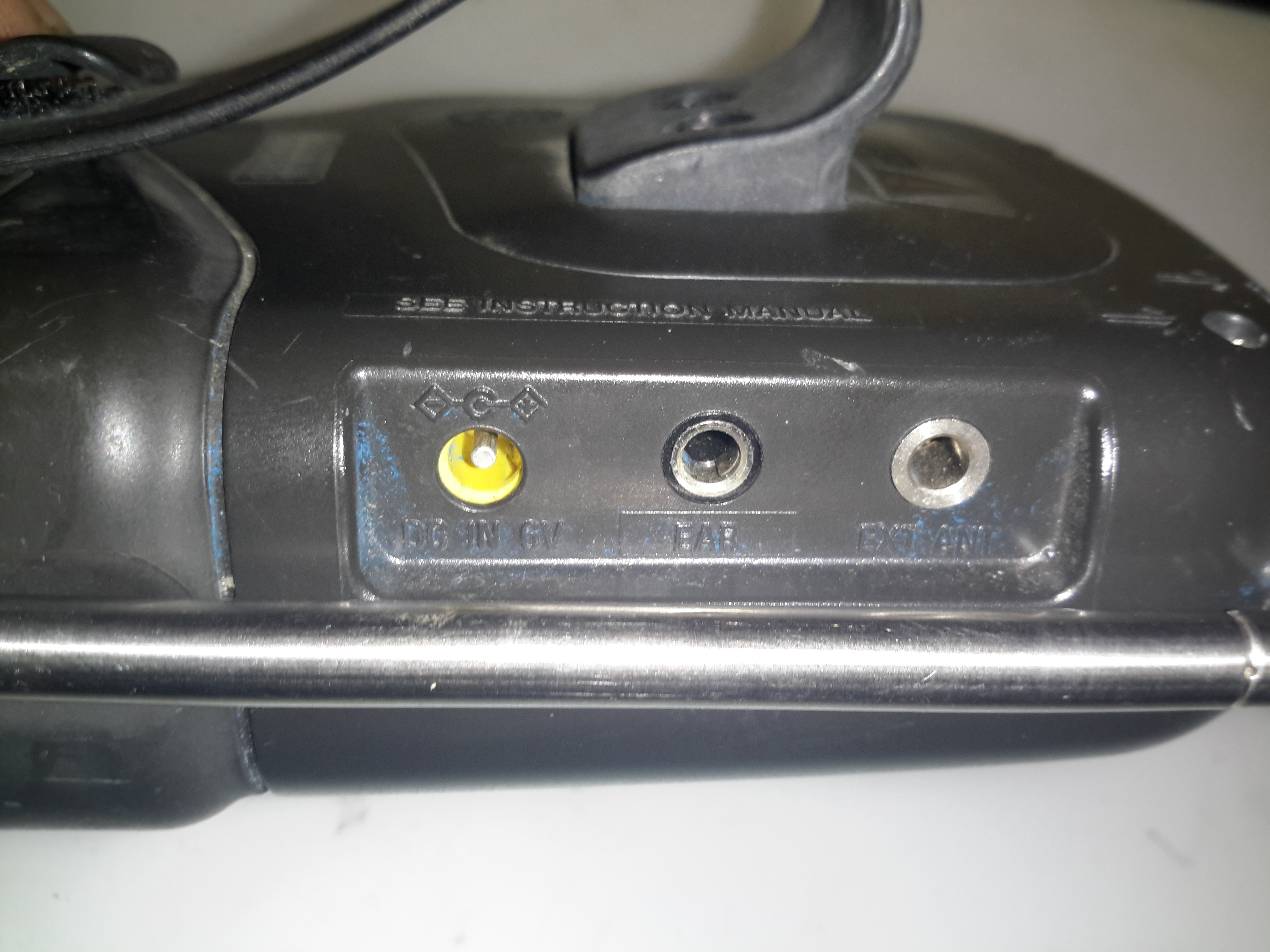
External Inputs
Still not much in the way of inputs on this TV. There’s an external power input, external antenna input & a headphone jack. No composite from the factory. (Hack incoming ;)).
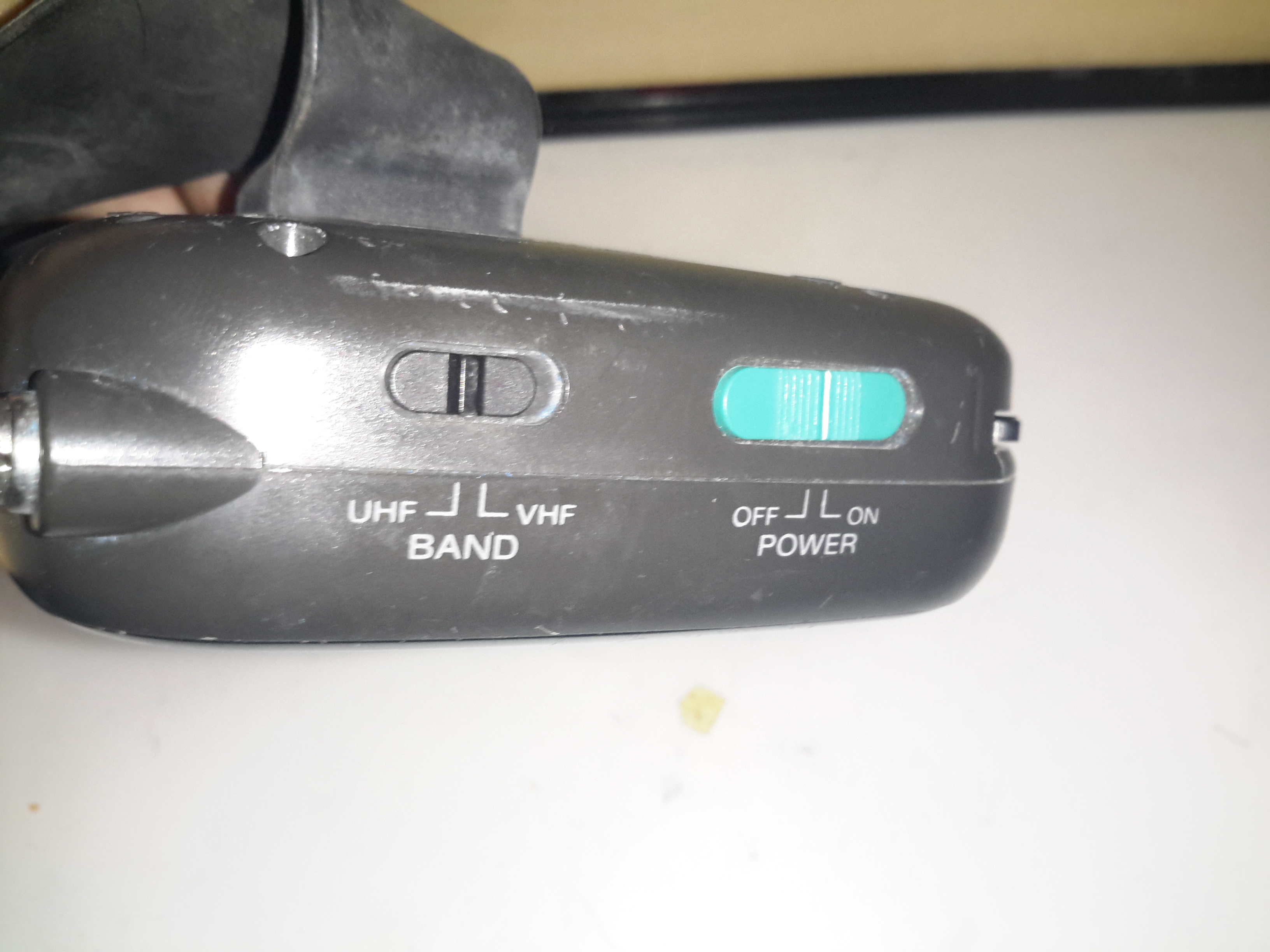
Power / Band
The UHF/VHF & power switches are on the top of this model.
Back Cover Removed
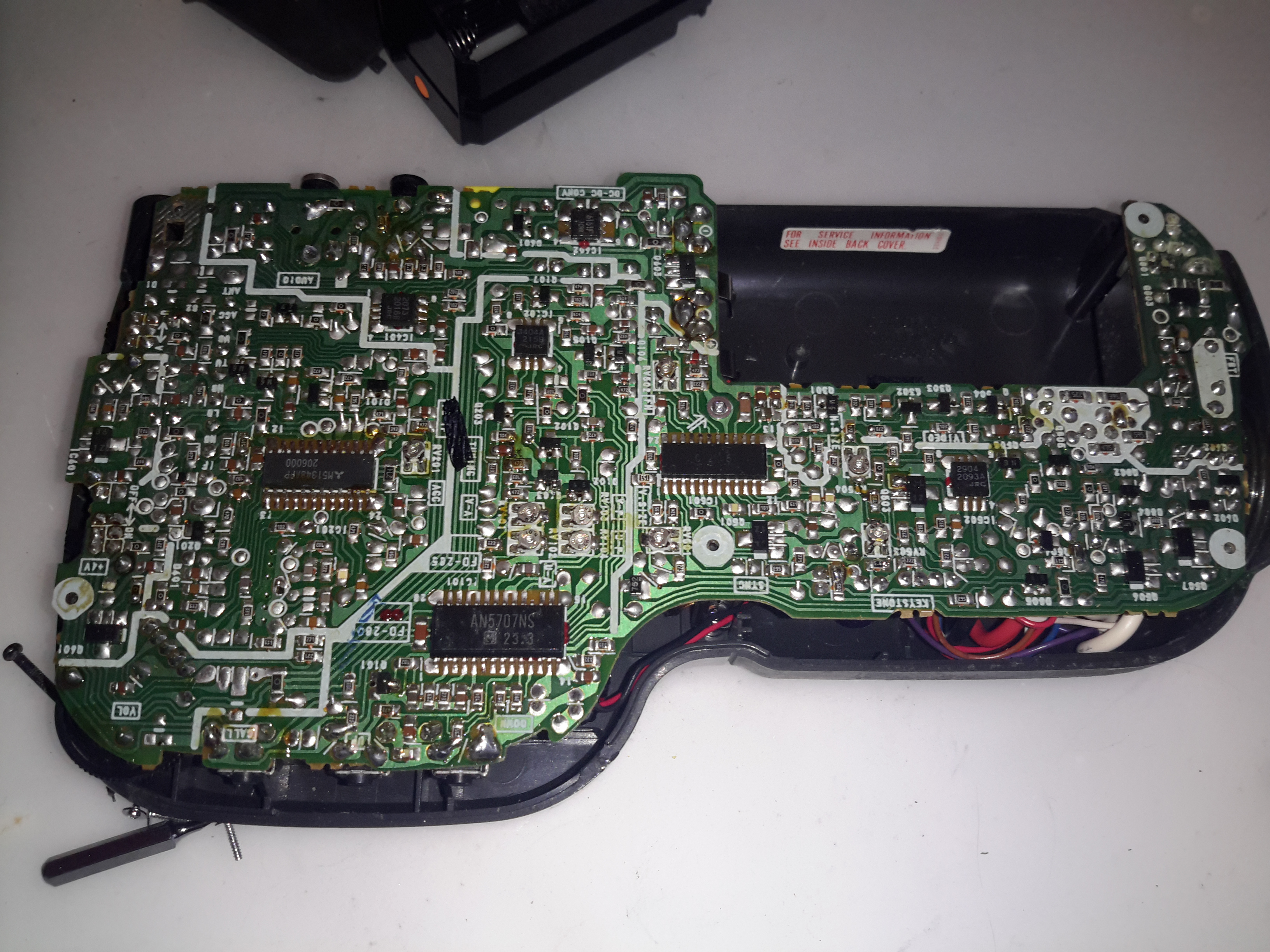
Removing some very tiny screws allows the back to be removed. There’s significant difference in this model to the last, more of the electronics are integrated into ICs, nearly everything is SMD.
RF Section
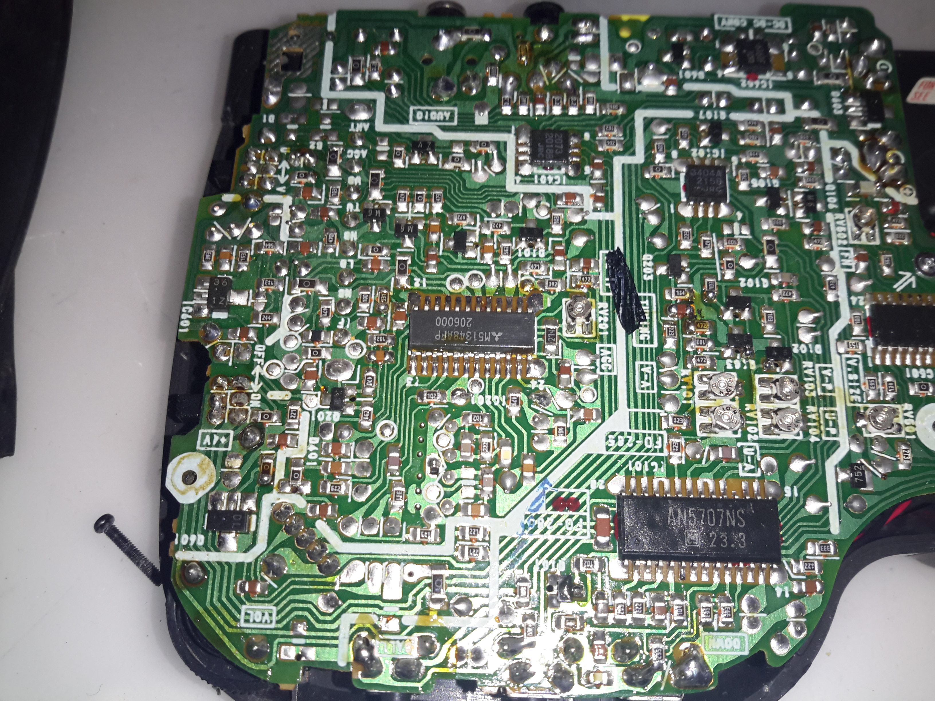
There’s the usual RF tuner section & IF, in this case the VIF/SIF is a Mitsubishi M51348AFP.
Tuner Controller
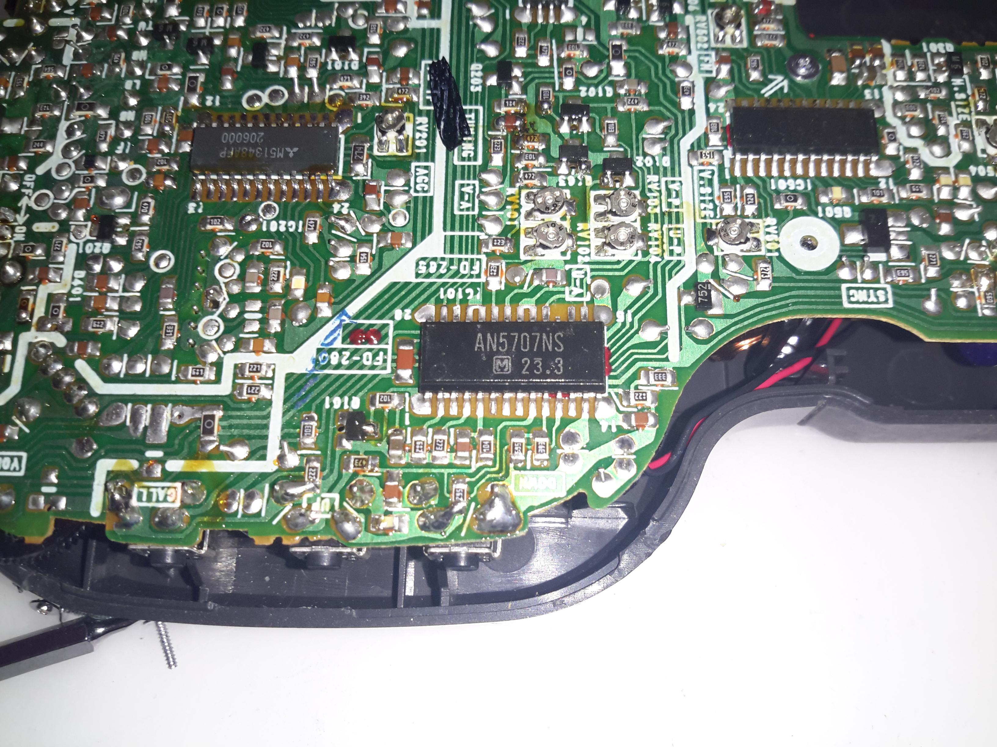
The digital control of the tuner is perfomed by this Panasonic AN5707NS.
Deflection / Sync
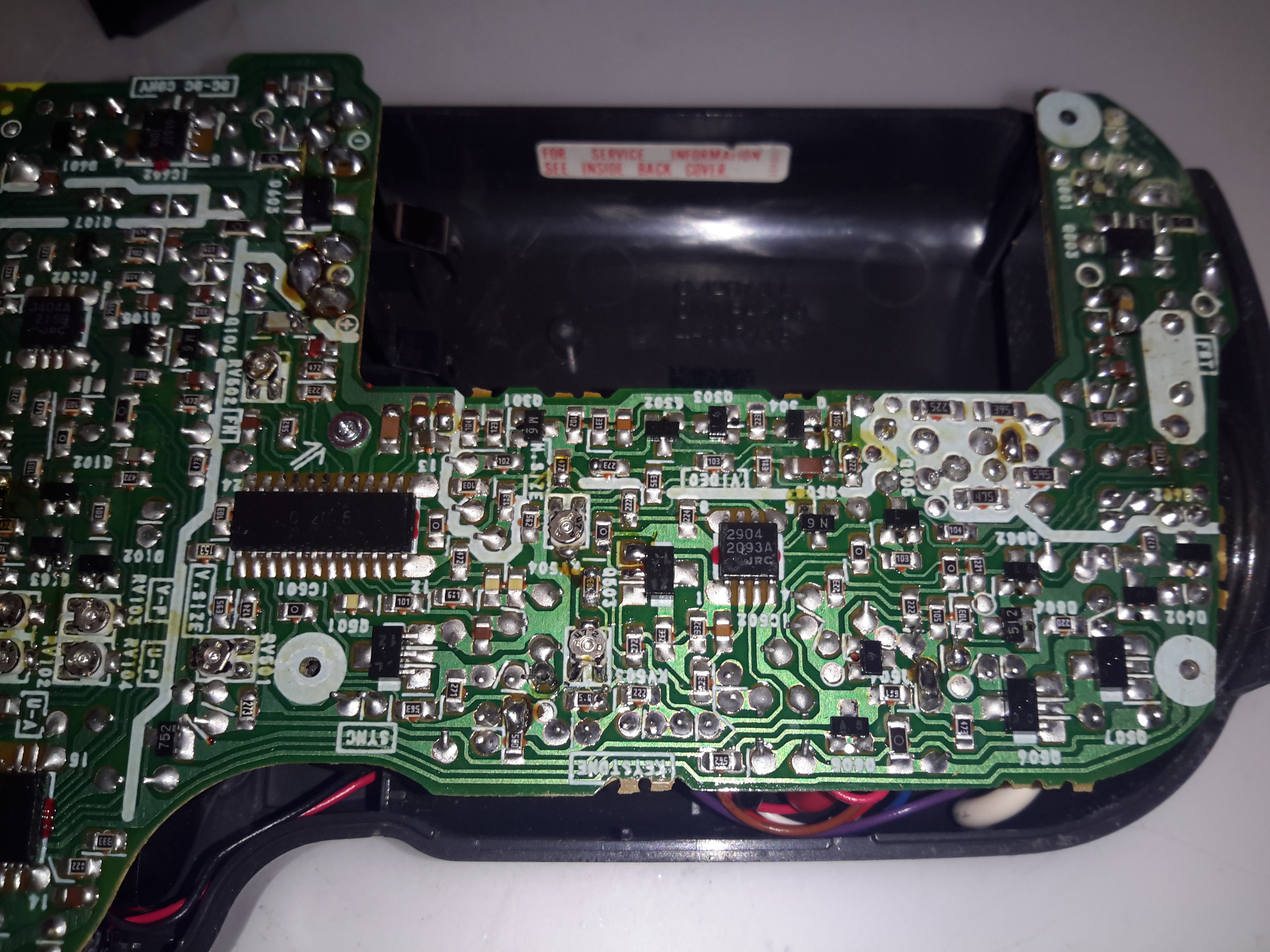
The deflection & sync functions appear to be controlled by a single Sony branded custom IC, the CX20157. Similar to many other custom Sony ICs, a datasheet for this wasn’t forthcoming.
PCB Top
There’s very little on the top side of the board, the RF section is on the left, there’s a DC-DC converter bottom centre next to the battery contacts. This DC-DC converter has a very unusual inductor, completely encased in a metal can. This is probably done to prevent the magnetic field from interfering with the CRT.
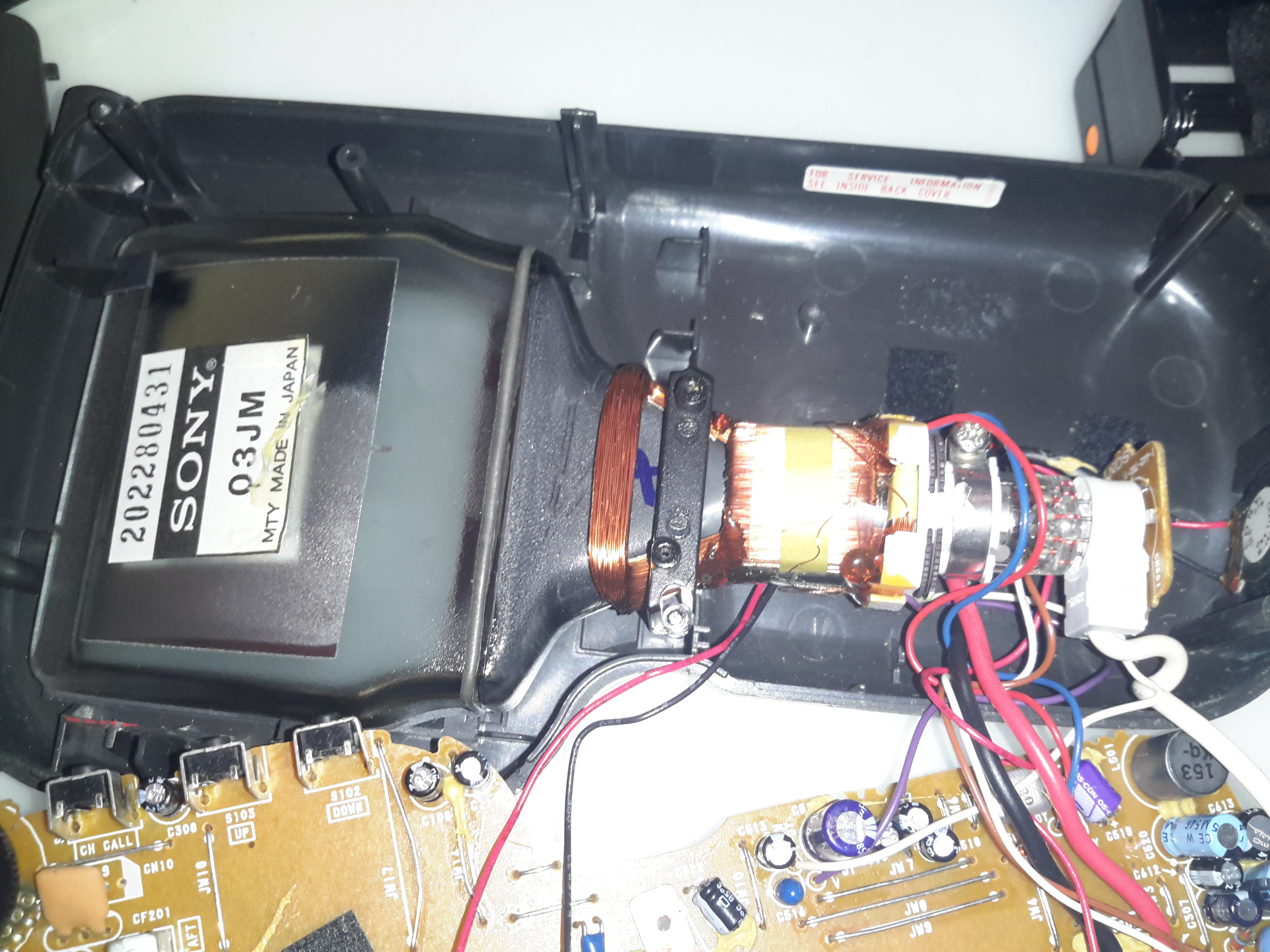
CRT
Here’s the CRT itself, the Sony 03-JM. The back of this CRT is uncoated at the bottom, the tuning scale was taped to the back so it lined up with the tuning bar displayed on the screen.
Electronics
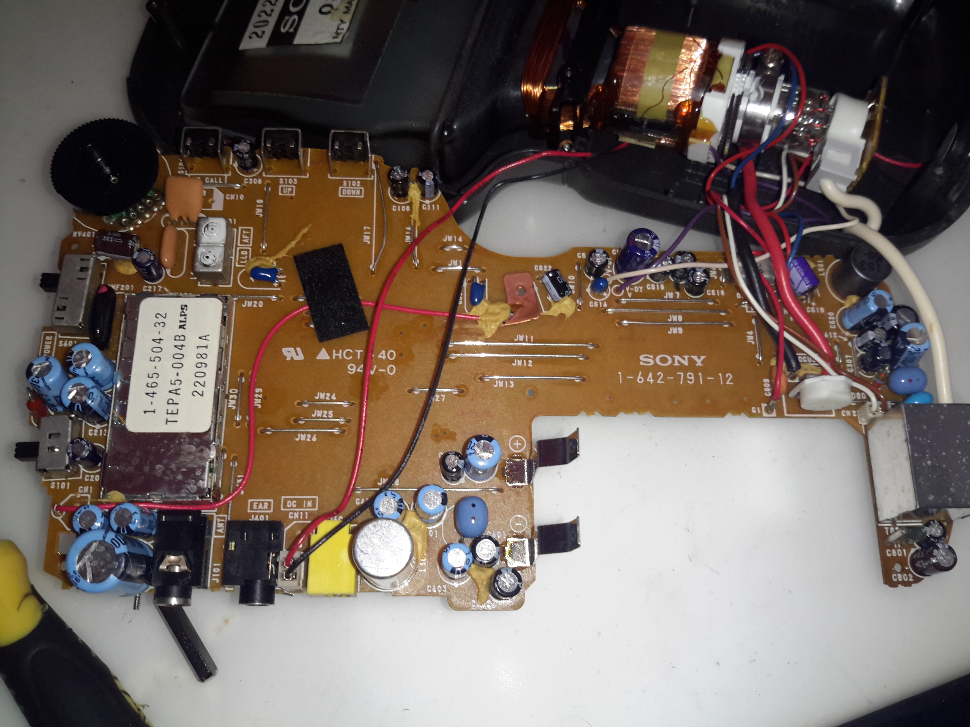
Here’s the electronics completely removed from the shell. There’s much more integration in this model, everything is on a single PCB.
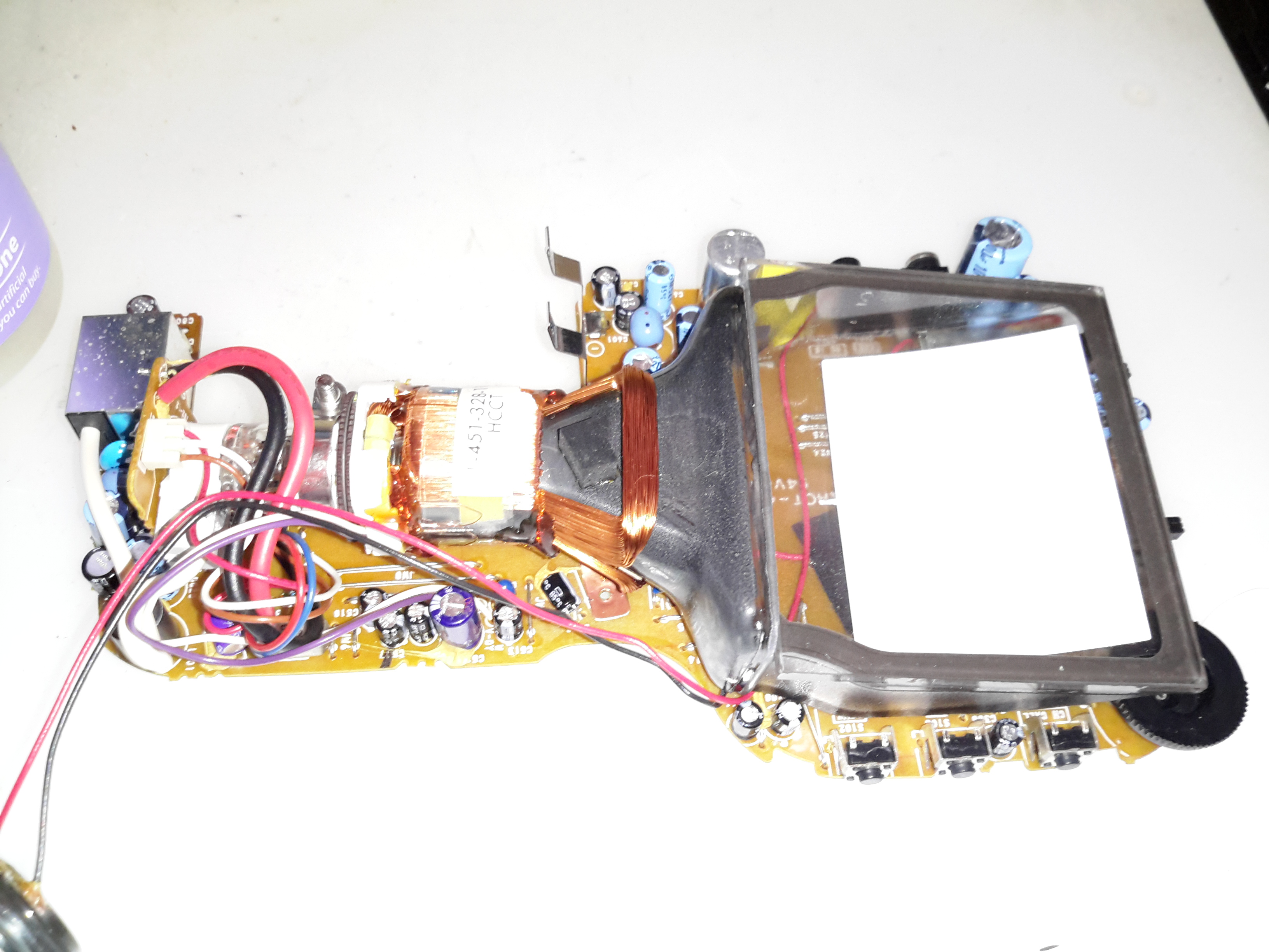
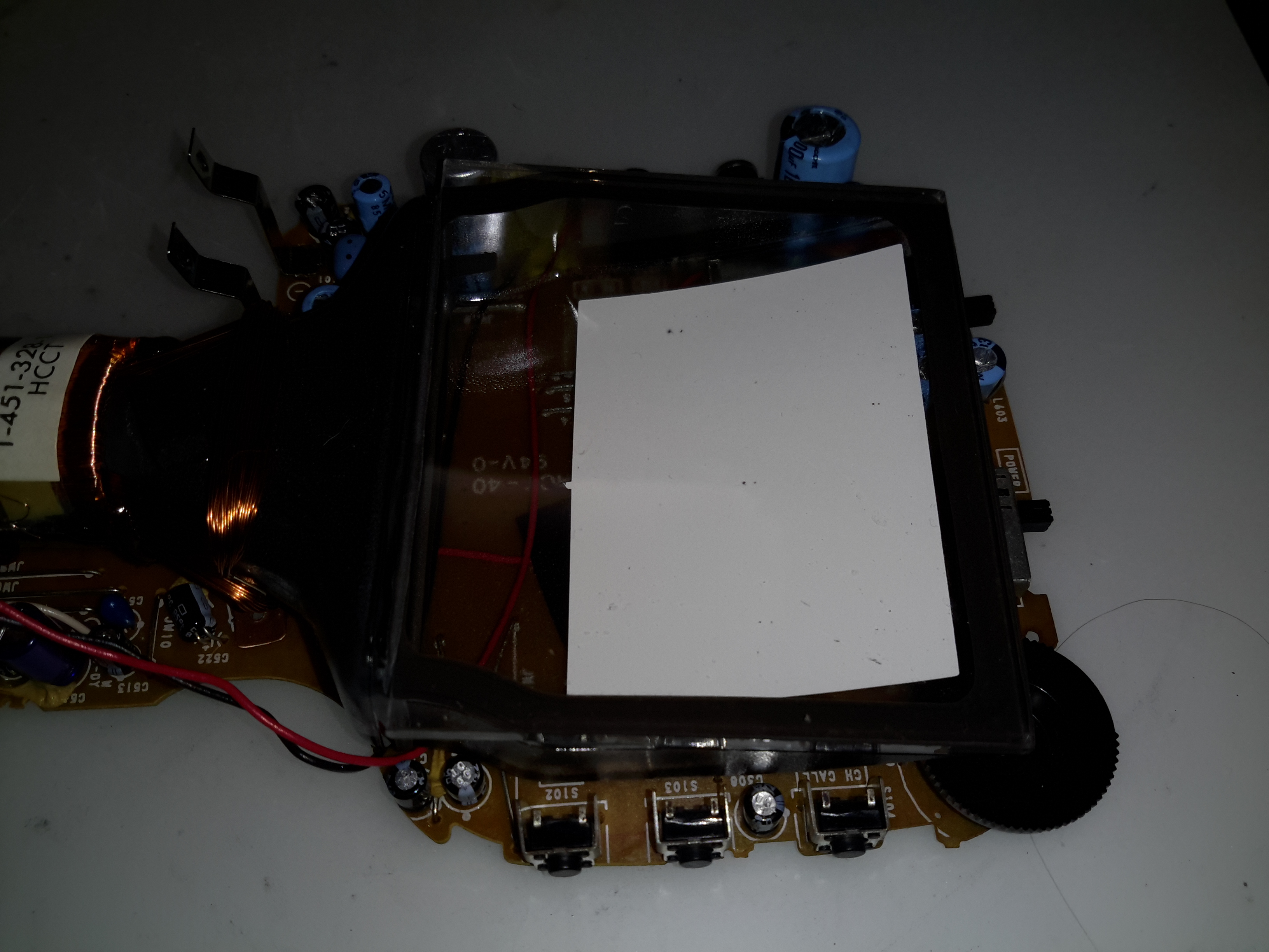
Phosphor Screen
The curve in the phosphor screen can clearly be seen here. This CRT seems to have been cost-reduced as well, with the rough edges on the glass components having been left unfinished.
Electron Gun
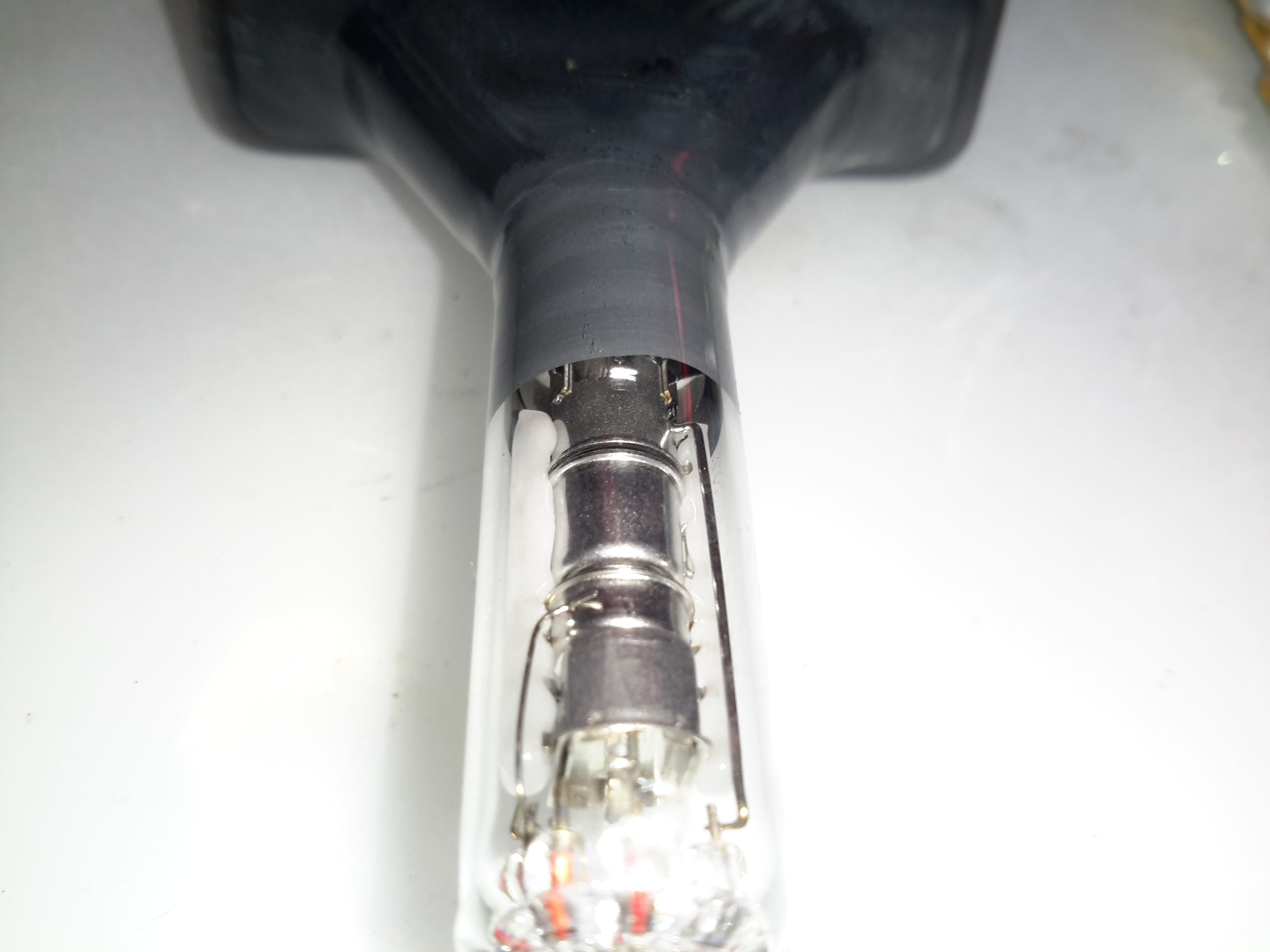
Here’s the electron gun end of the tube. There isn’t a separate final anode connection to the bell of the tube unlike the previous model. Instead the final anode voltage is on a pin of the electron gun itself. This keeps all the wiring to the tube at one end & shortens the high voltage cable.
Electron Gun
Here’s the gun in the neck of the tube. Again this is pretty much standard fare for CRT guns. It’s more similar to a viewfinder tube in that the anode connection is running from the pins at the back. (It’s the line running up the right side of the tube). I’m guessing the anode voltage is pretty low for this to work without the HV flashing over, probably in the 2-4kV range.
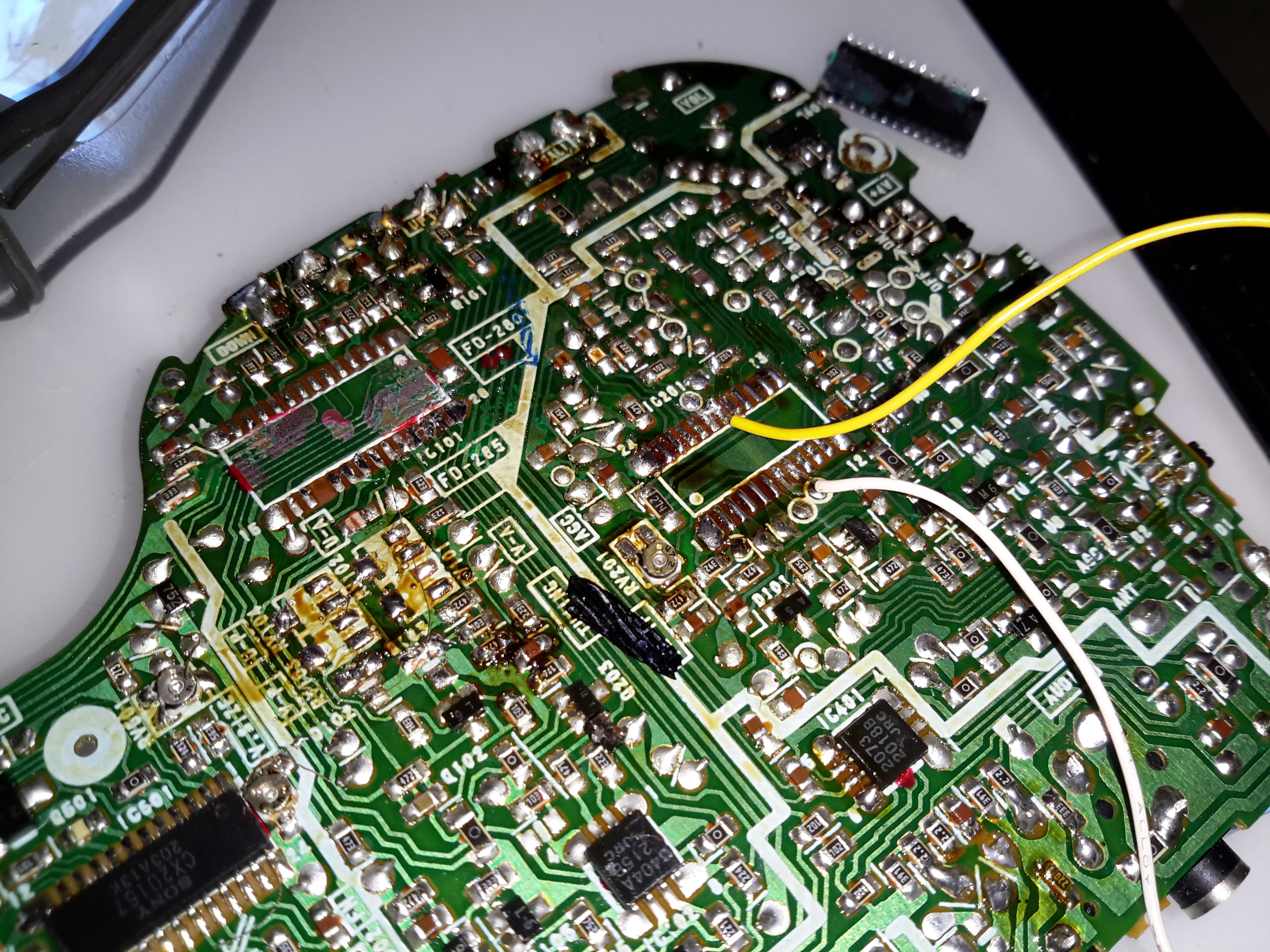
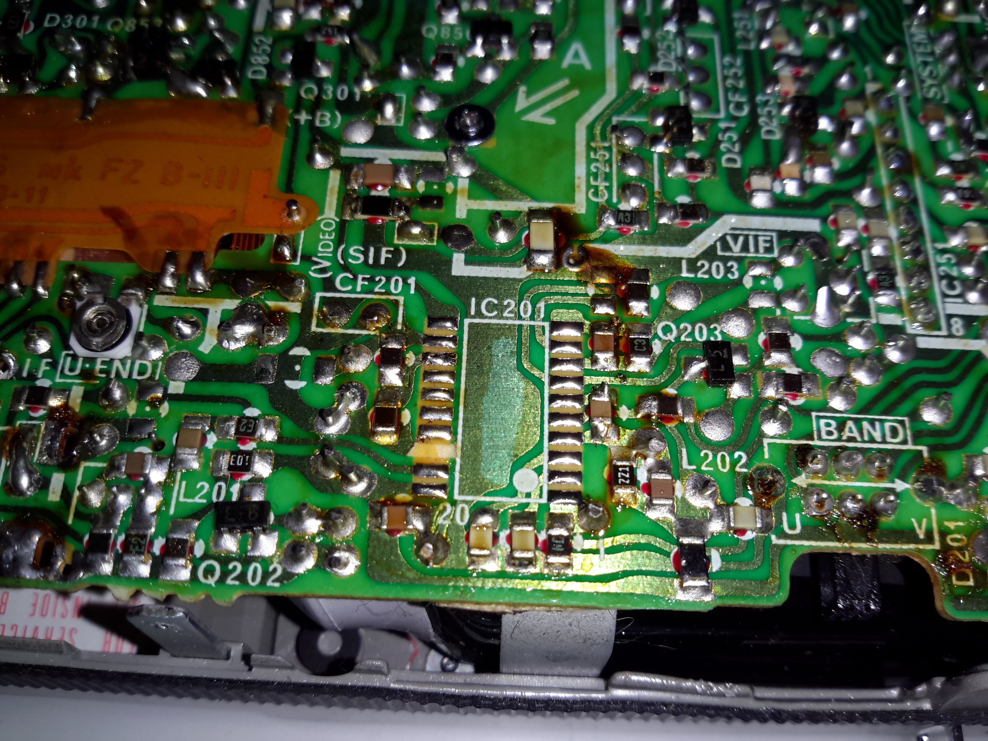
Hacking the Sony FD-20 to accept a composite input is easy – the tuner receives the RF transmission, produces an IF, this is then fed into IC201, a Mitsubishi M51364P Video IF Processor. The VIF IC then separates out the composite video signal, which is output on Pin 13 (in photo above, left side, 3rd pin from the top). The audio is separated out & sent via Pin 11 to the Audio IF processor.
In the above photo, the VIF IC has been removed from the board with hot air, as it was interfering with the signal if left in place. The RF tuner was also desoldered & removed. Unfortunately I managed to mangle a pad, which is the ground pin for the VIF IC. This isn’t much of an issue though, as an identical signal ground is available, just to the left of the IC.
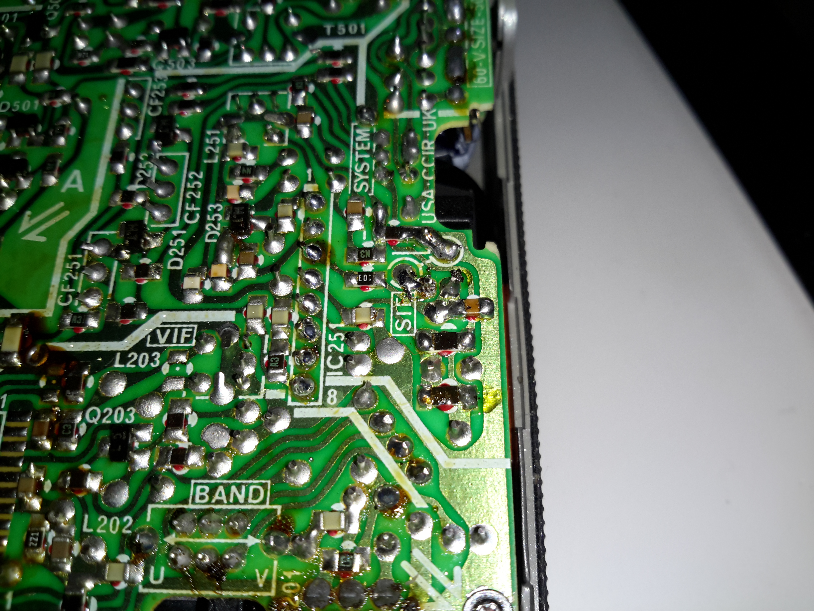
Audio Input
The audio can be tapped into in a similar way, the circled pad in the centre of the photo marked SIF is the place, this is the output of the Audio IF processor to the audio amplifier. The Audio IF processor didn’t interfere with the injected signal, so it was left in place.
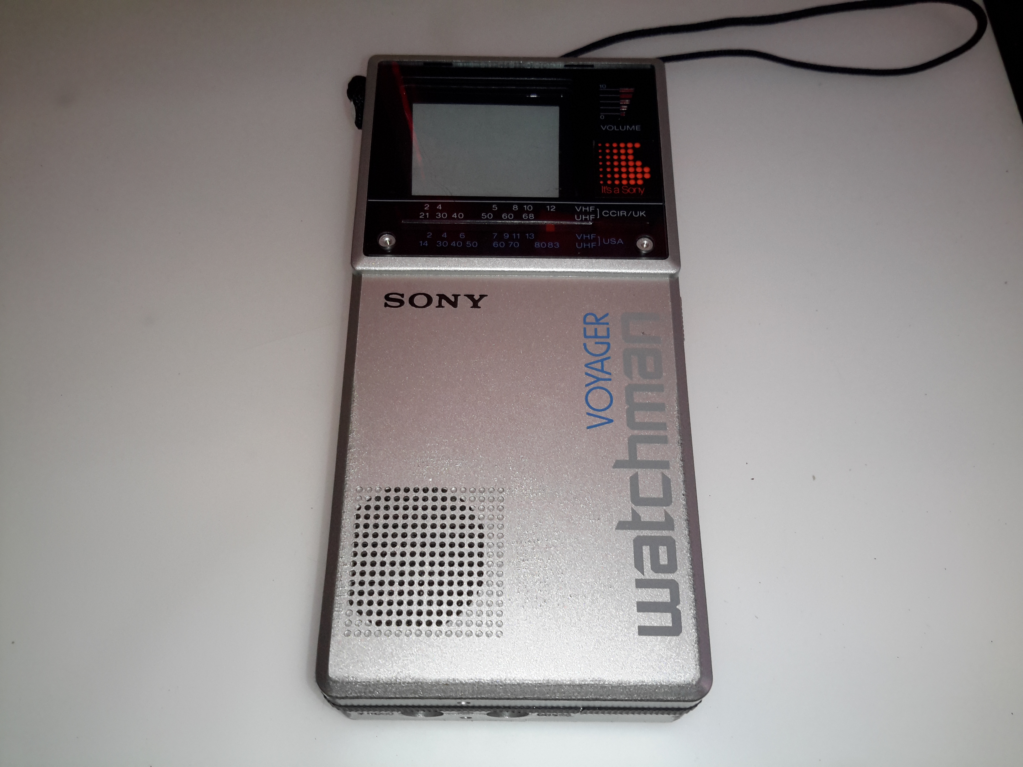
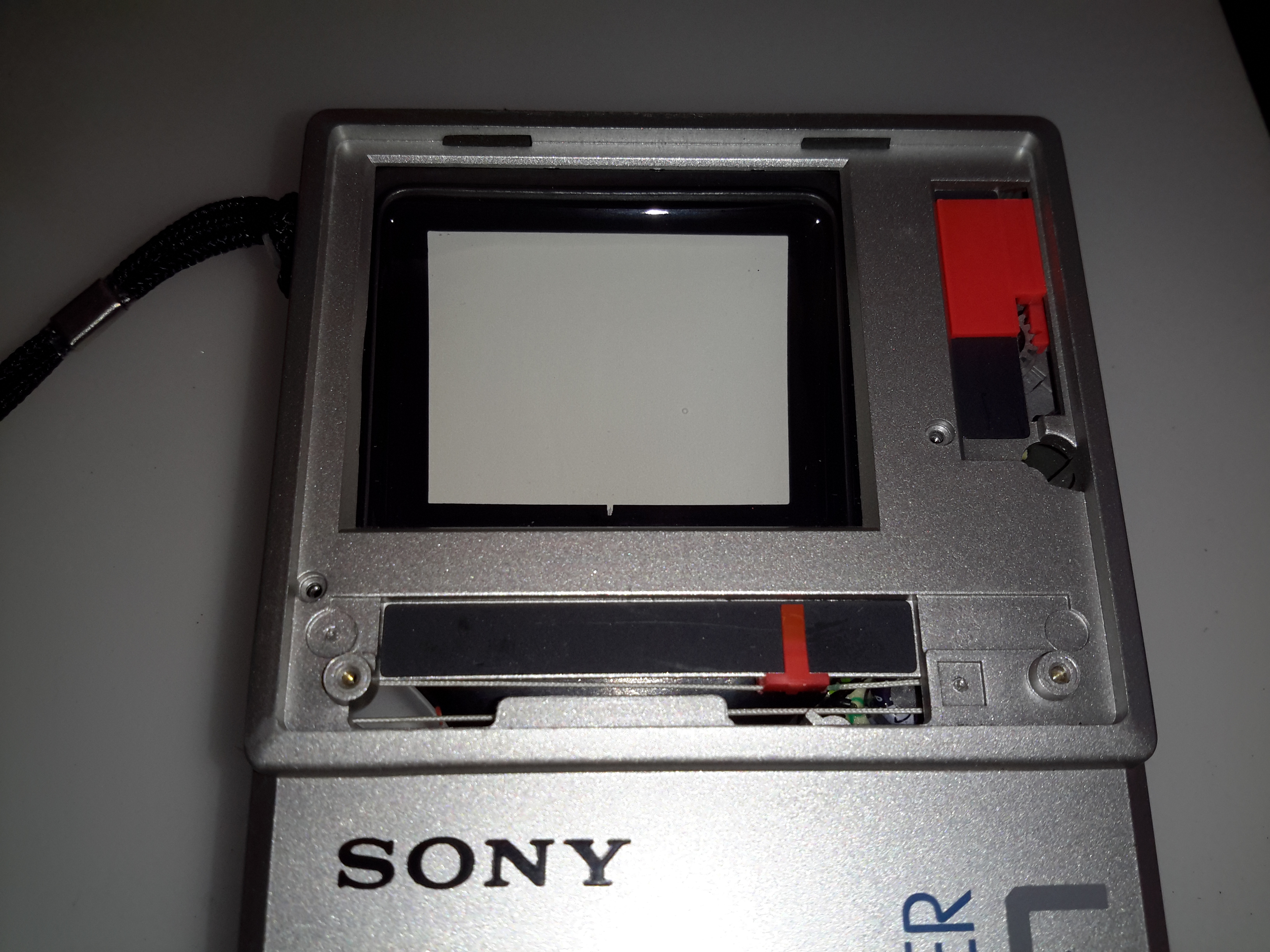
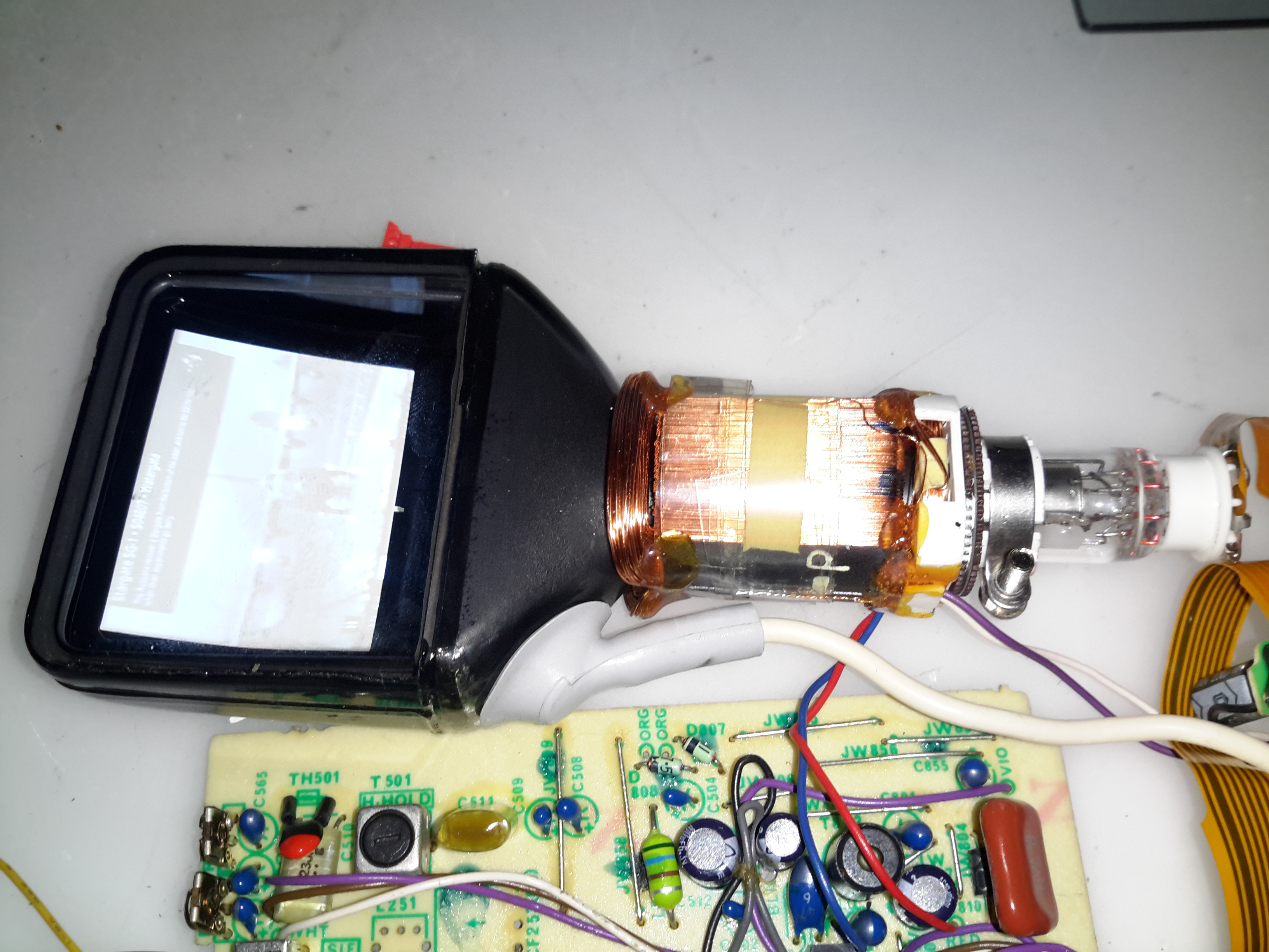
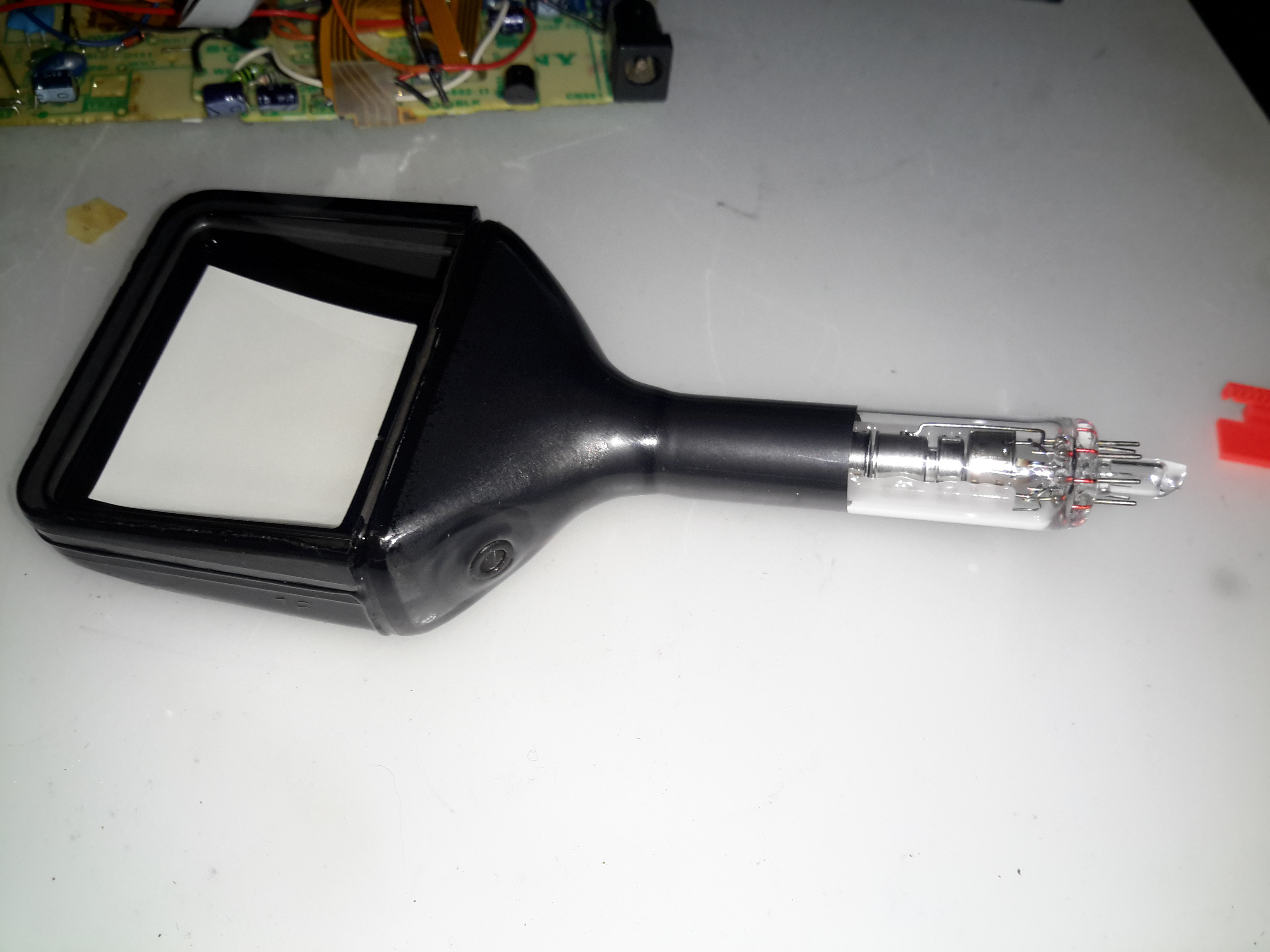
Here’s an oddity from the 1980’s – a CRT-based portable TV, with a very strangely shaped tube. Sony produced many types of flat CRTs back in the 80’s, with the electron gun at 90° to the curved phosphor screen.
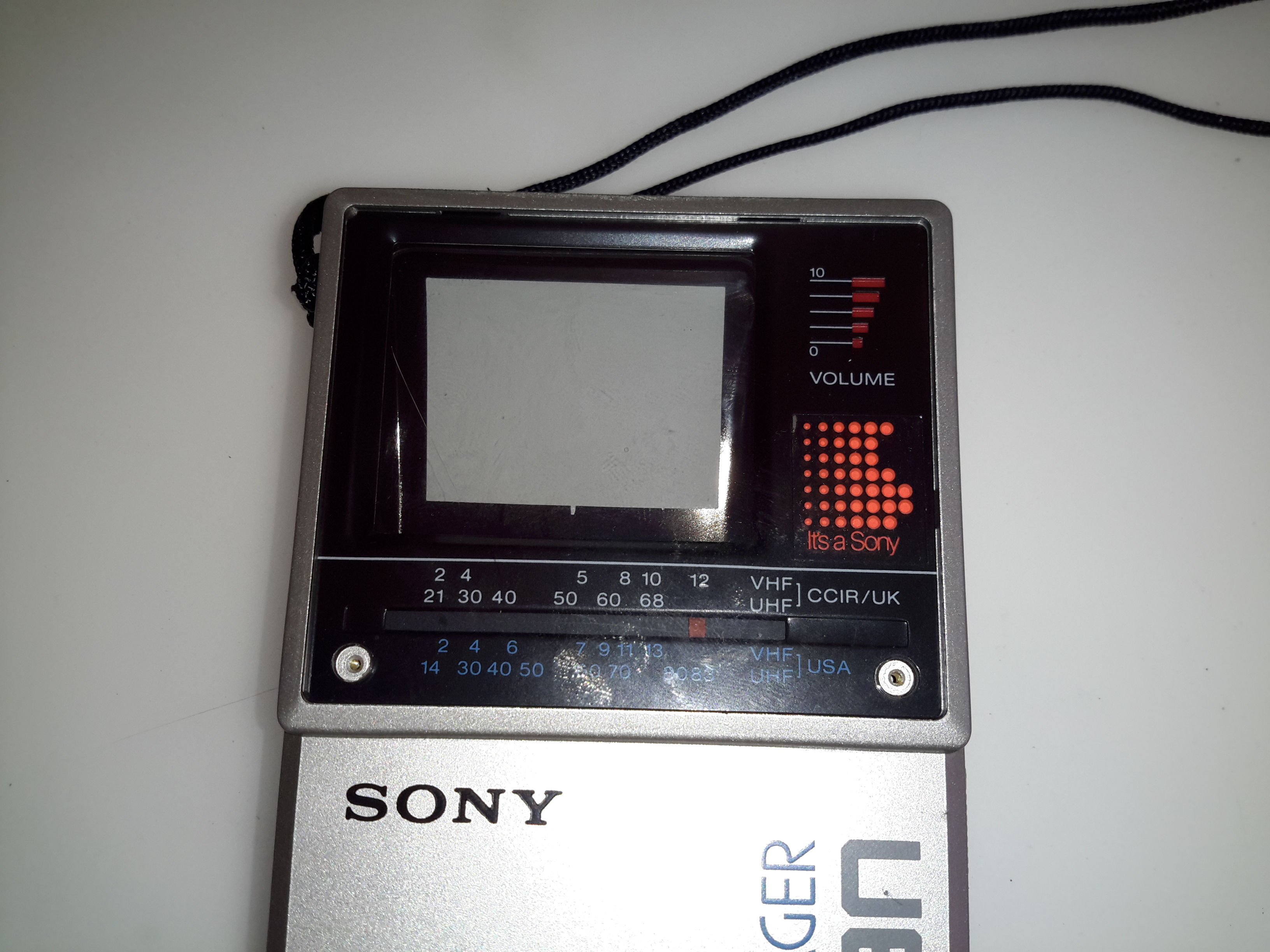
Front Panel
The front panel has the display window, along with the tuning & volume indicators. Unfortunately since analogue TV transmissions have long been switched off, this unit no longer picks up any transmissions off the air, but it can be modified to accept a composite video input.
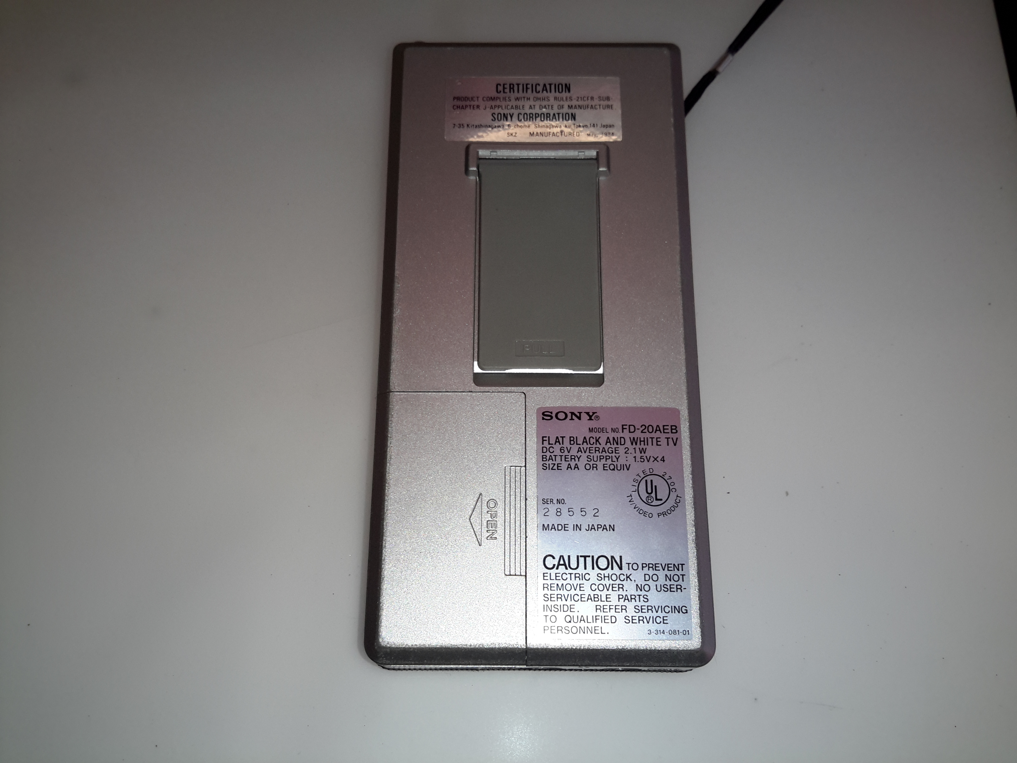
Back Panel
The back panel has the battery compartment & the tilt stand.
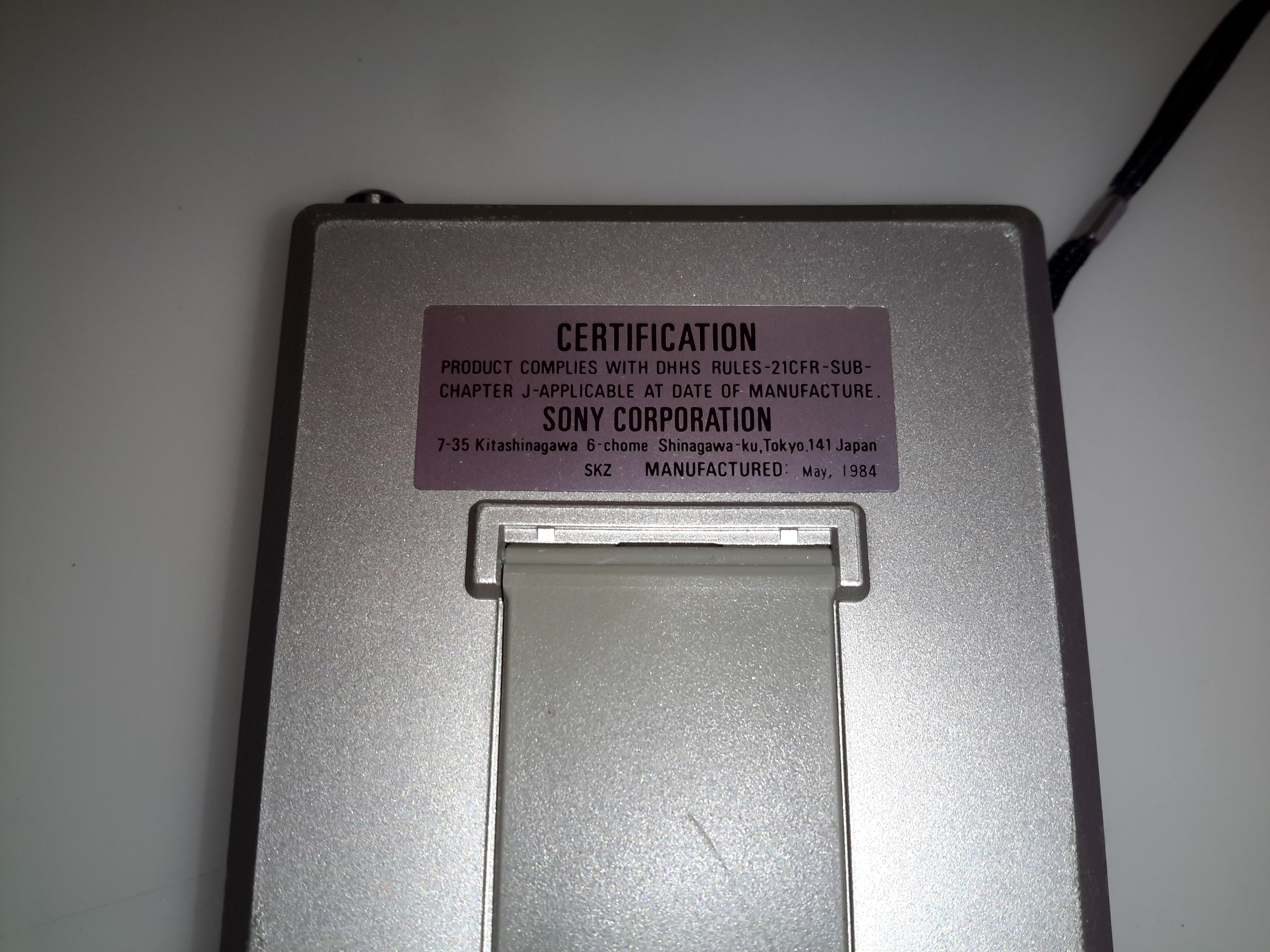
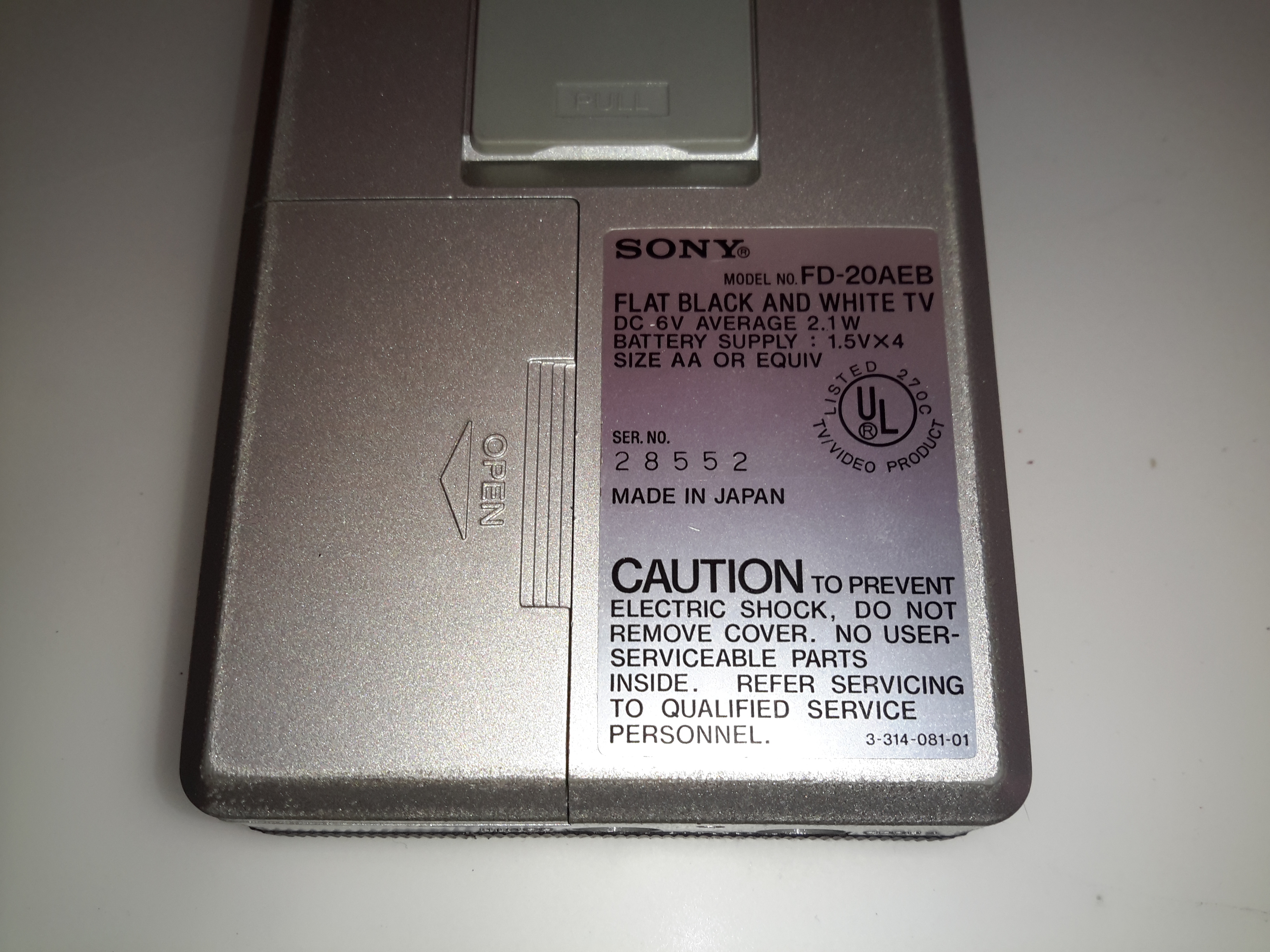
Certification
The certification label reveals this unit was manufactured in May 1984, 32 years ago!
Spec. Label
Rated at 6v, ~2.1W this device uses surprisingly little power for something CRT based.
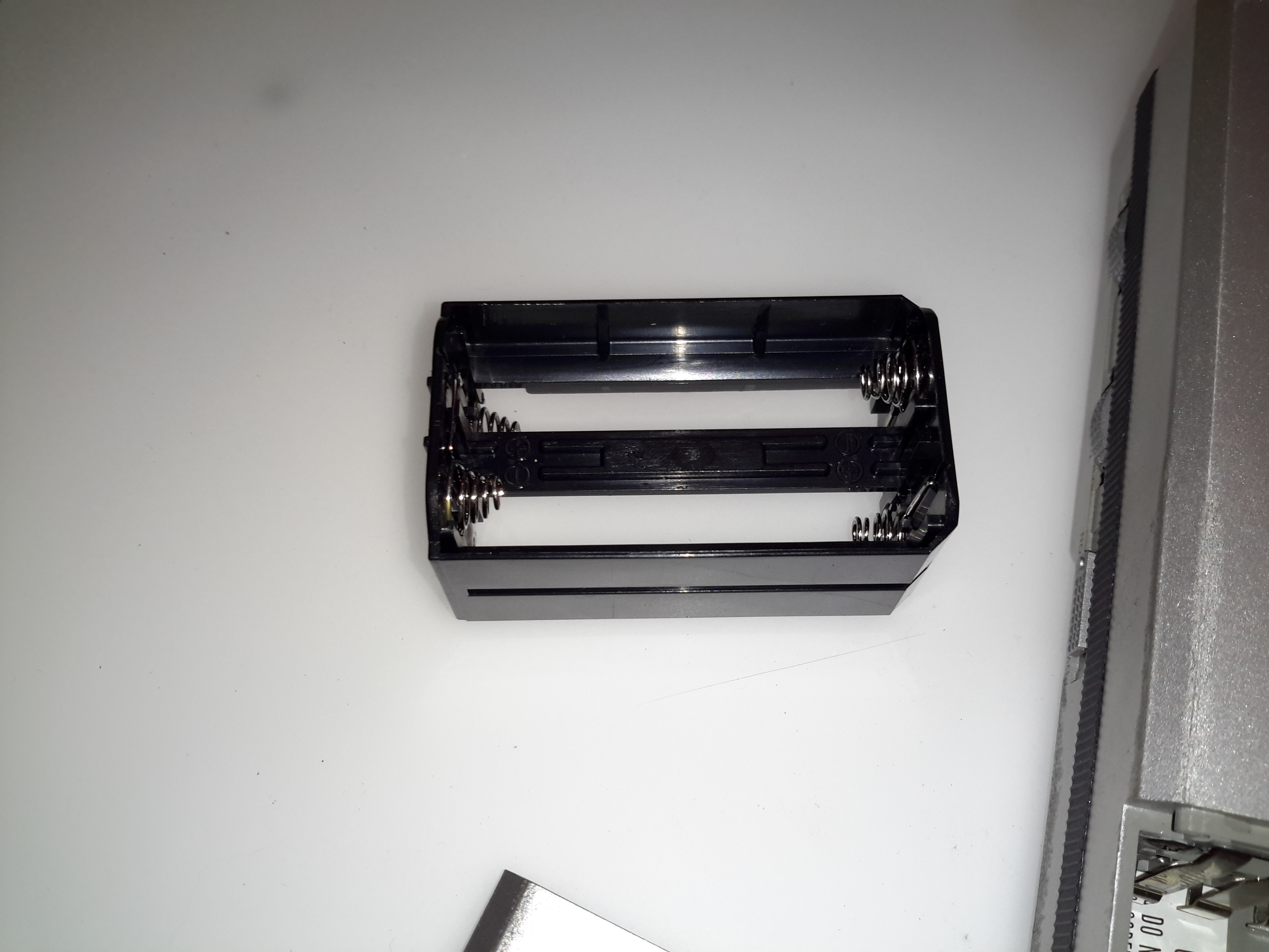
Battery Holder
The battery holder is a little unique, this plastic frame holds 4 AA cells, for a 6v pack.
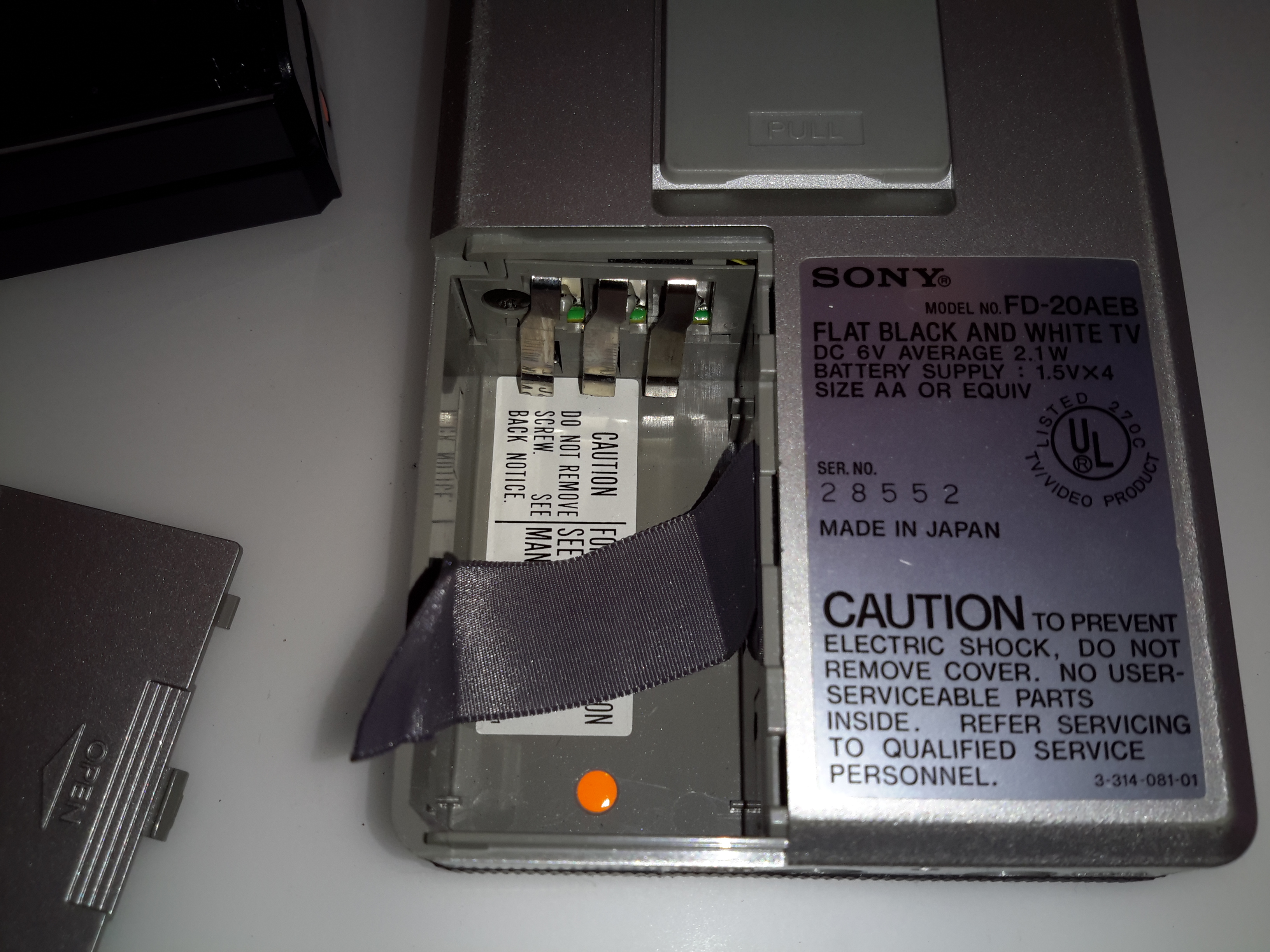
Battery Compartment
The battery holder slots into the back of the TV, there’s also an extra contact that the service manual mentions is for charging, so I assume a rechargeable 6v battery pack was also available.
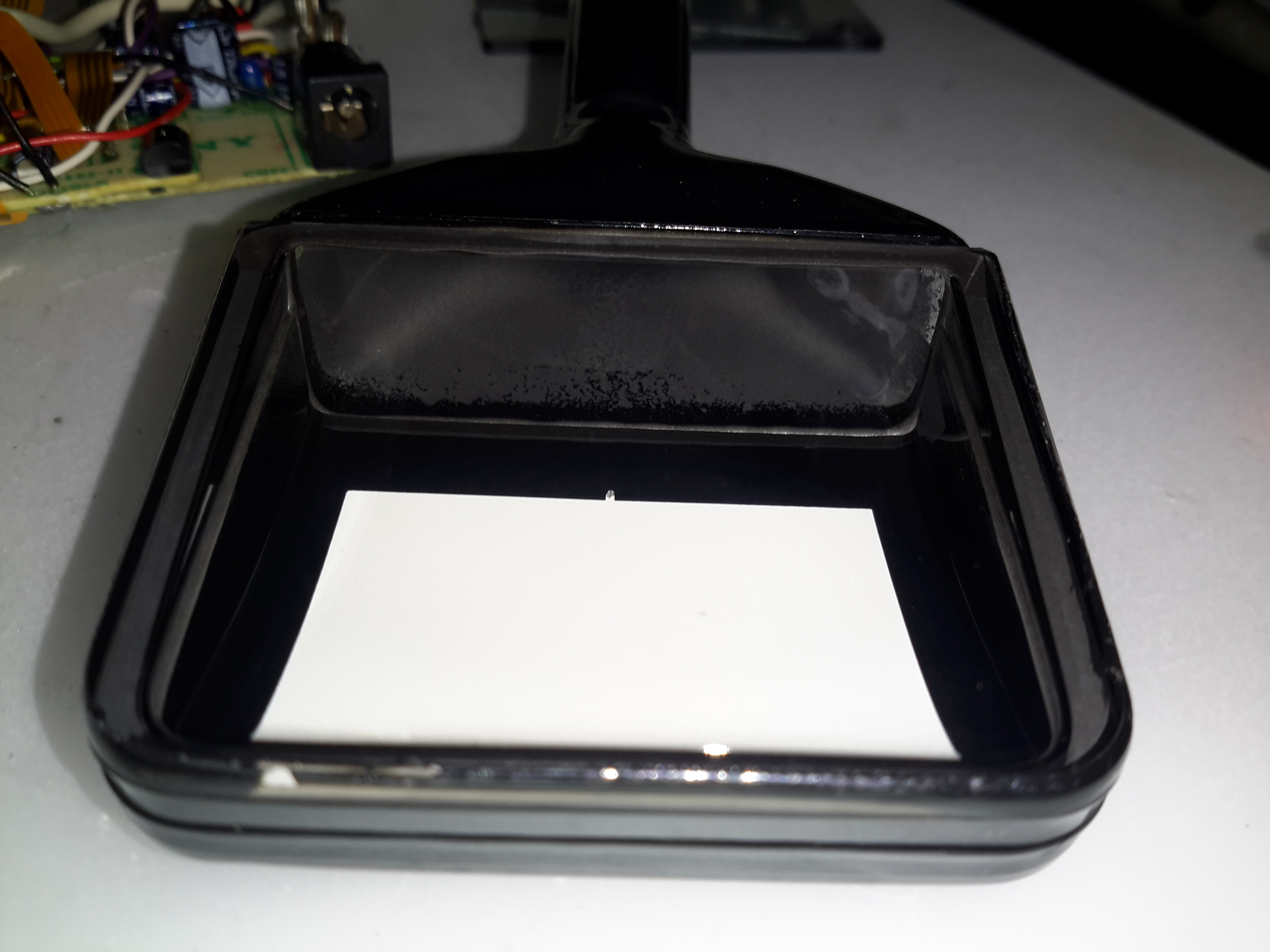
Front Panel Removed
Removing a pair of pin-spanner type screws allows the front glass & screen printed CRT surround to be removed. Not much more under here other than the pair of screws that retain the CRT in the front frame.
Back Cover Removed
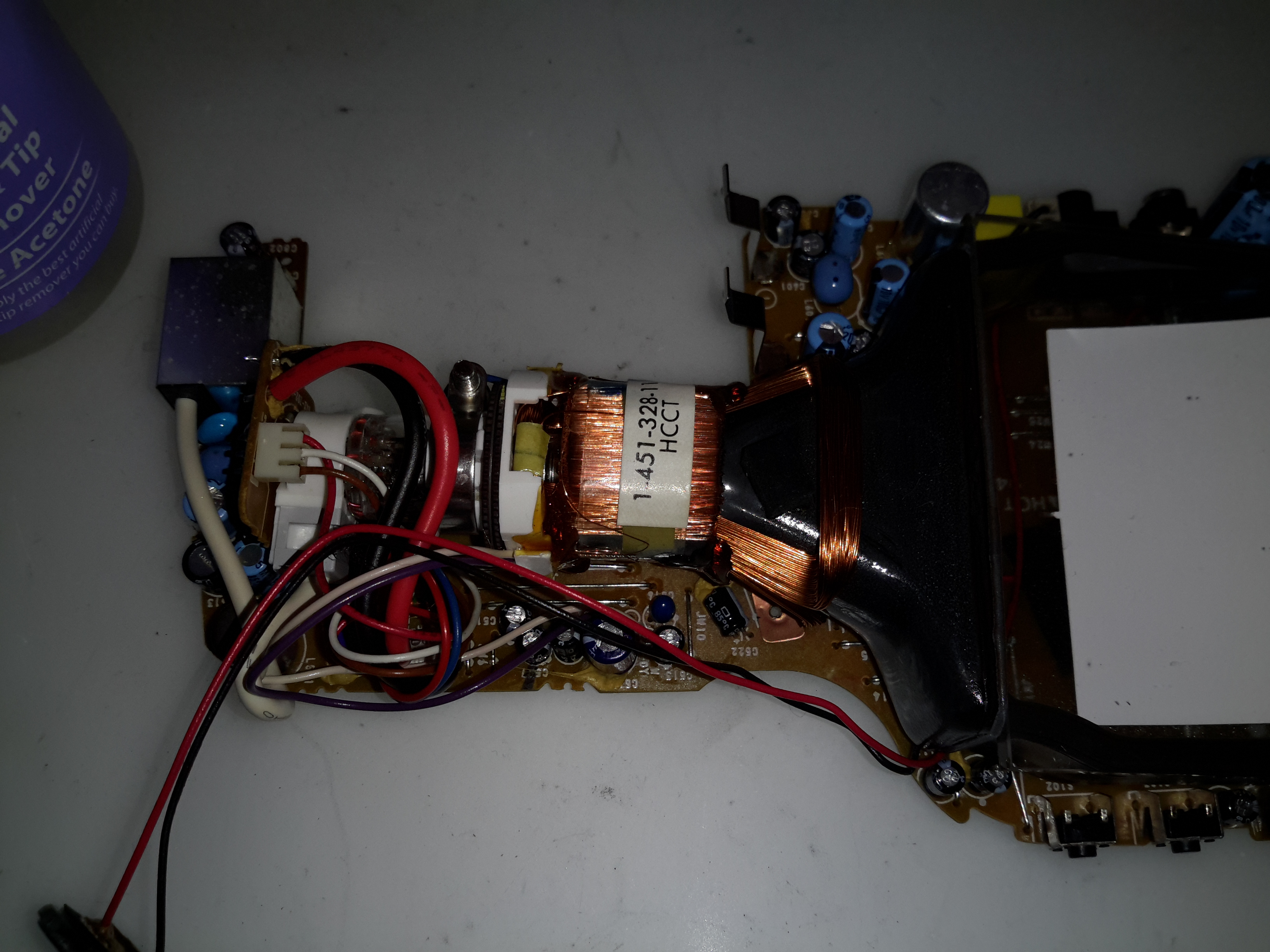
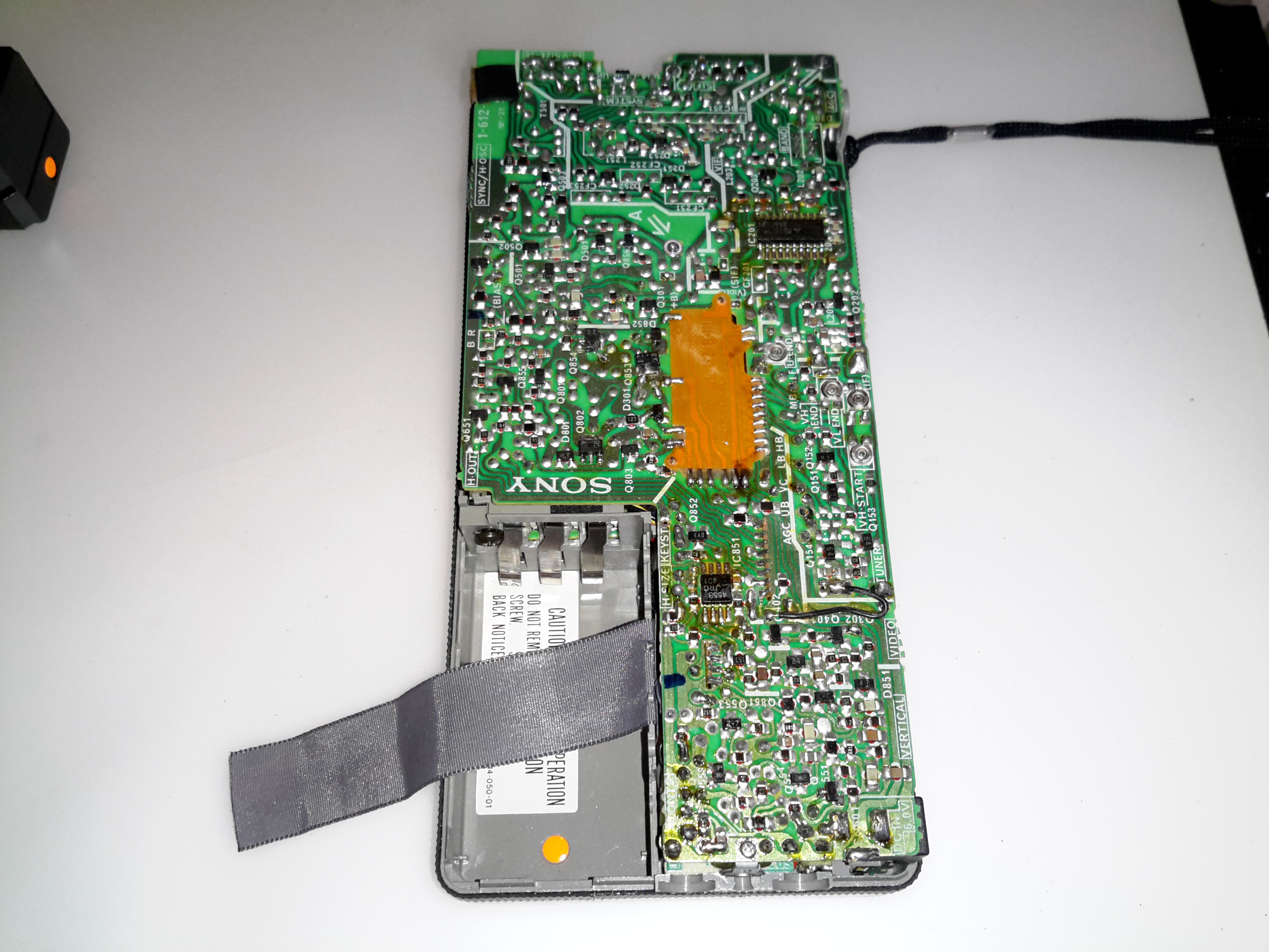
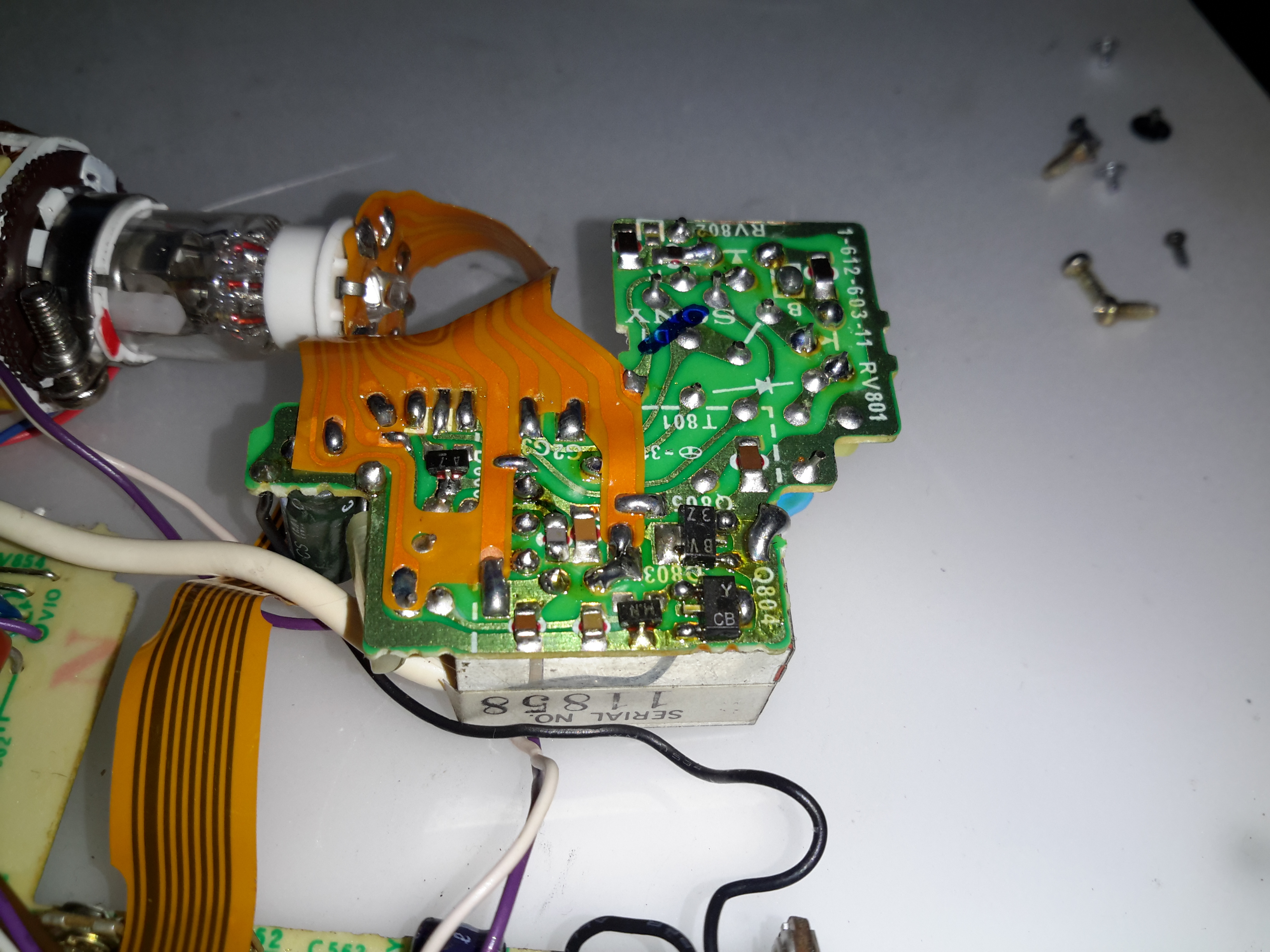
Here’s the back cover removed, after unscrewing some very small screws. As per usual with Sony gear, the electronics is extremely compacted, using many flat flex cables between the various PCBs. The main PCB is visible at the back, this has all the deflection circuitry, RF tuner, Video IF, Audio IF, video amplifier & composite circuitry.
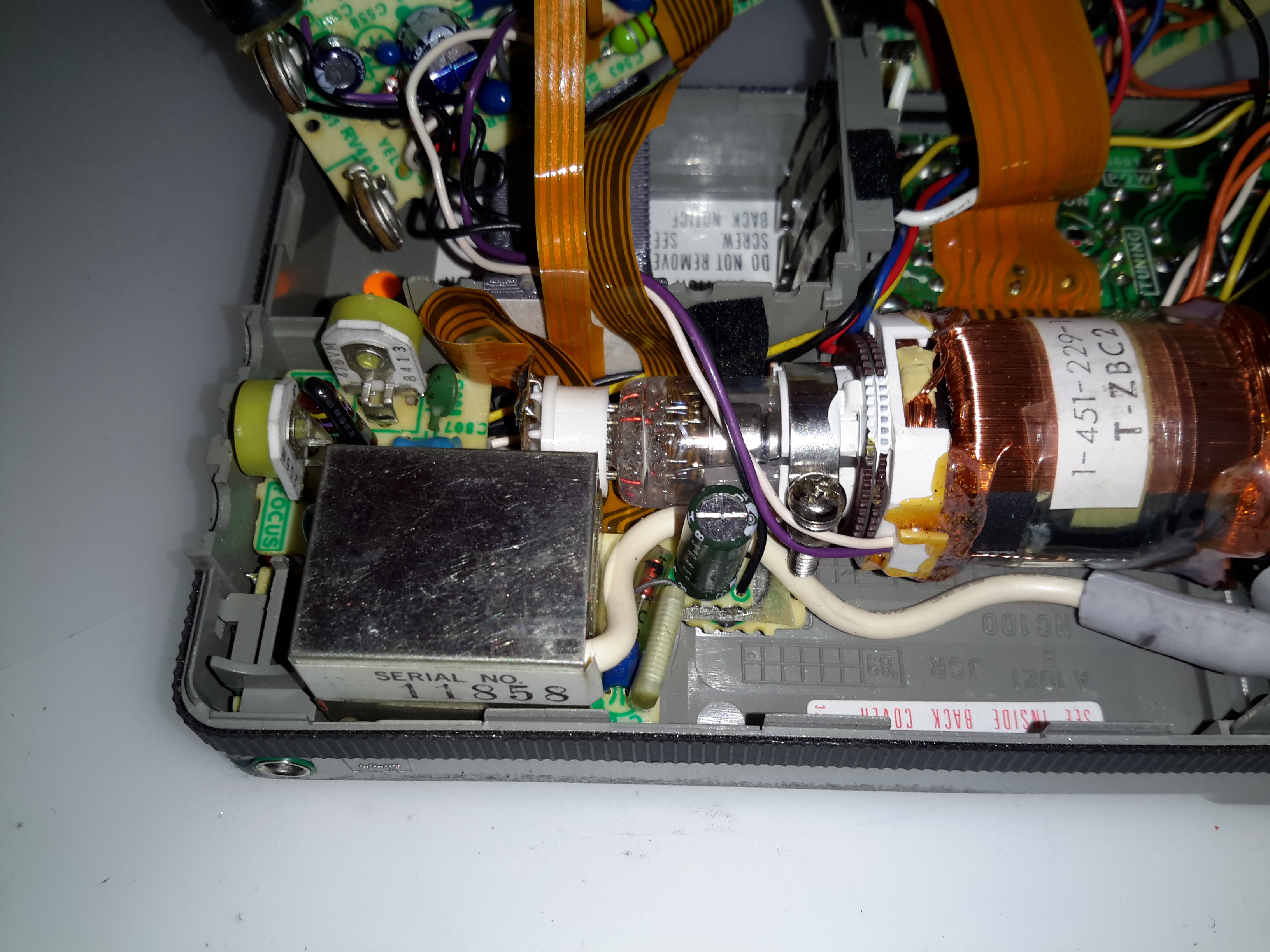
CRT Electron Gun & Flyback Transformer
Lifting up the main board reveals more PCBs – the high voltage section for the CRT with the flyback transformer, focus & brightness controls is on the left. The loudspeaker PCB is below this. The CRT electron gun is tucked in behind the flyback transformer, it’s socket being connected to the rest of the circuitry with a flat flex cable.
CRT Rear
Here’s the back of the CRT, the phosphor screen is on the other side of the curved glass back. These tubes must require some additional deflection complexity, as the geometry will change as the beam scans across the screen. There’s a dynamic focus circuit on the schematics, along with extensive keystone adjustments.
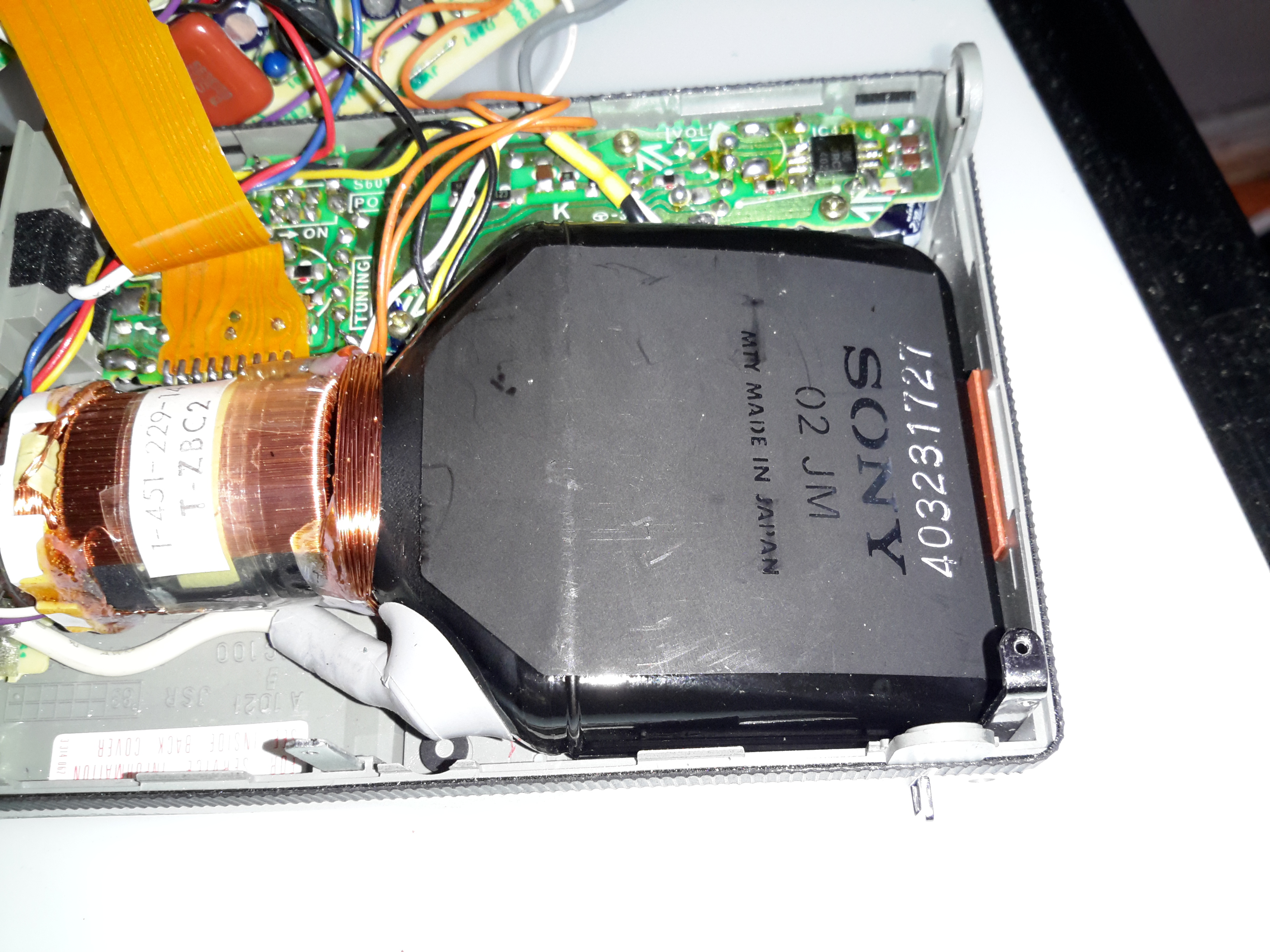
Sony 02-JM Flat CRT
Here’s the tube entirely extracted from the chassis. The EHT connection to the final anode is on the side of the tube bell, the curved phosphor screen is clearly visible. The one thing I can’t find in this CRT is a getter spot, so Sony may have a way of getting a pure enough vacuum that one isn’t required.
I’d expect the vertical deflection waveforms to be vastly different on this kind of CRT, due to the strange screen setup. Not much of a beam movement is required to move the spot from the top to the bottom of the screen.
HV Module
No doubt to keep the isolation gaps large, all the high voltages are kept on a separate small PCB with the flyback transformer. This board generates the voltages for the electron gun filament, focus grid & the bias to set the beam current (brightness) as well.
Bare CRT
Here the deflection yoke has been removed from the CRT, showing the very odd shape better. These tubes are constructed of 3 pieces of glass, the bell with electron gun, back glass with phosphor screen & front viewing window glass. All these components are joined with glass frit.
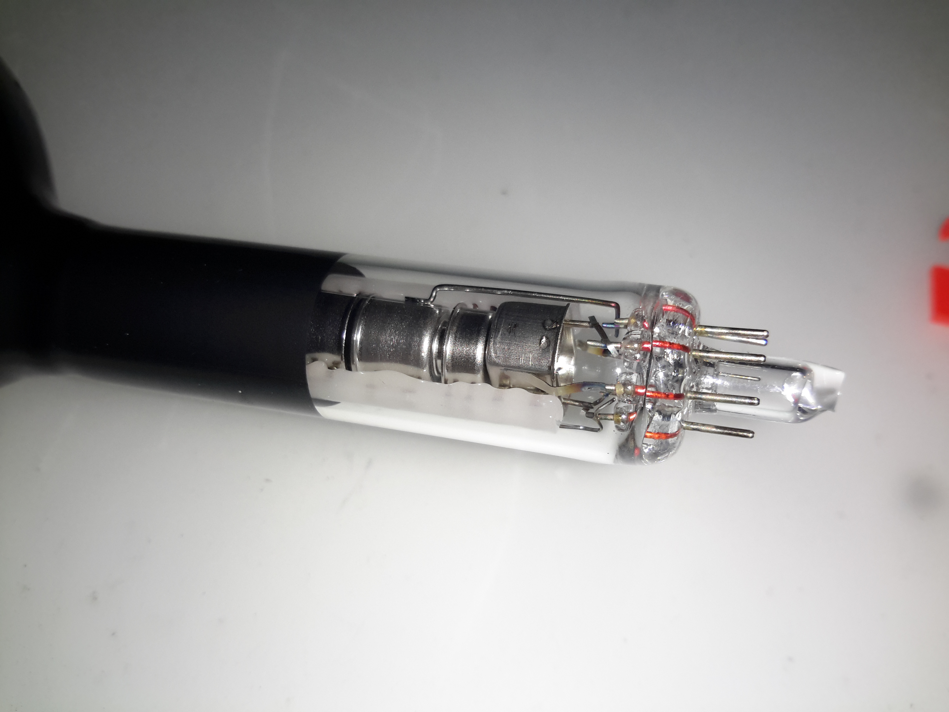
Electron Gun
The electron gun in the neck looks to be pretty much standard, with all the usual electrodes.
Viewing Window
Here’s a view from the very top of the CRT, the curve in the screen is very obvious here. The electron beam emerges from the bell at the back.
FD-20 Schematic
Here’s the full schematic of the entire TV, I extracted this from a service manual I managed to find online.
More to come on hacking this unit to accept a standard composite video input, from something such as a Raspberry Pi!
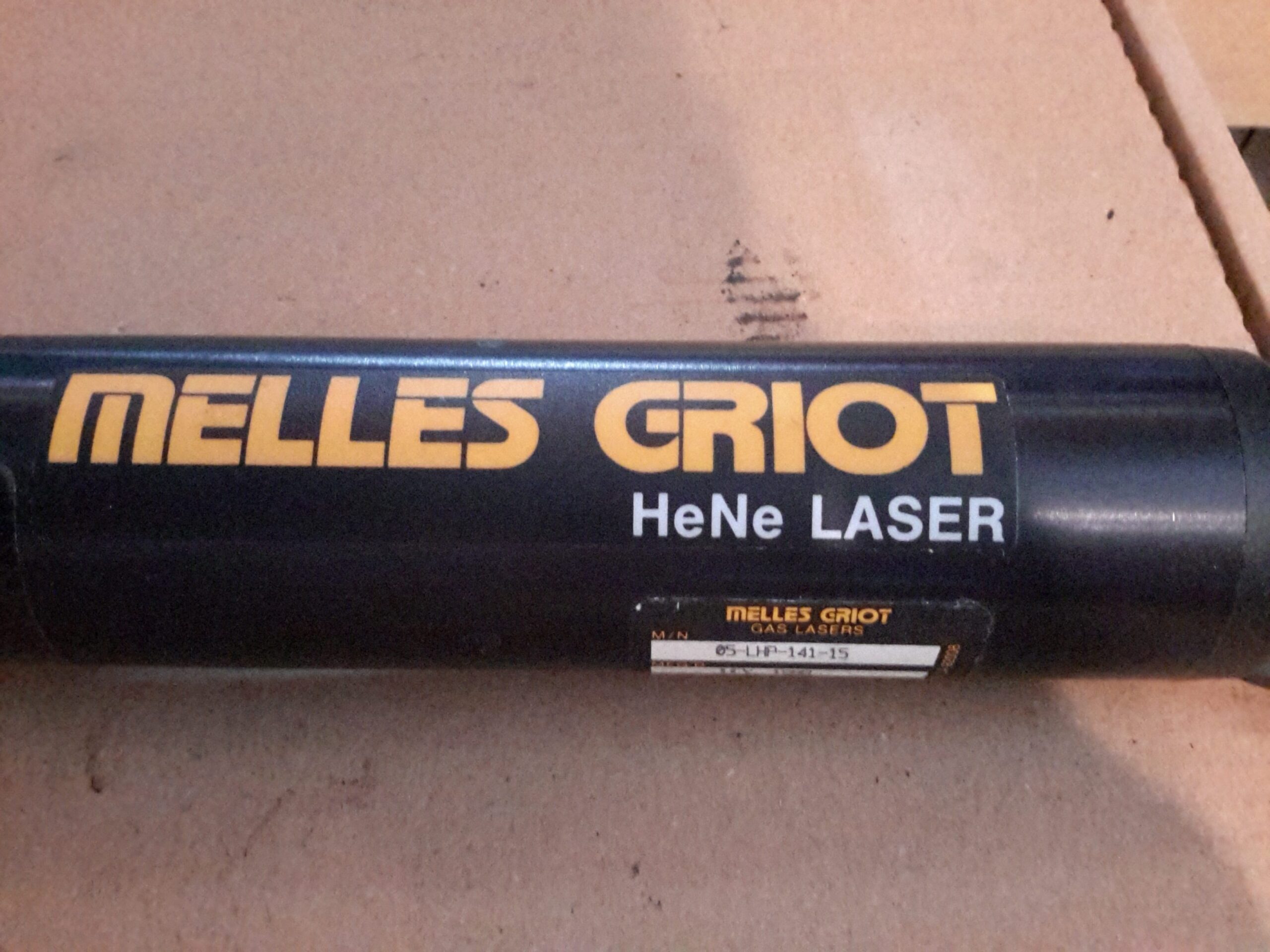
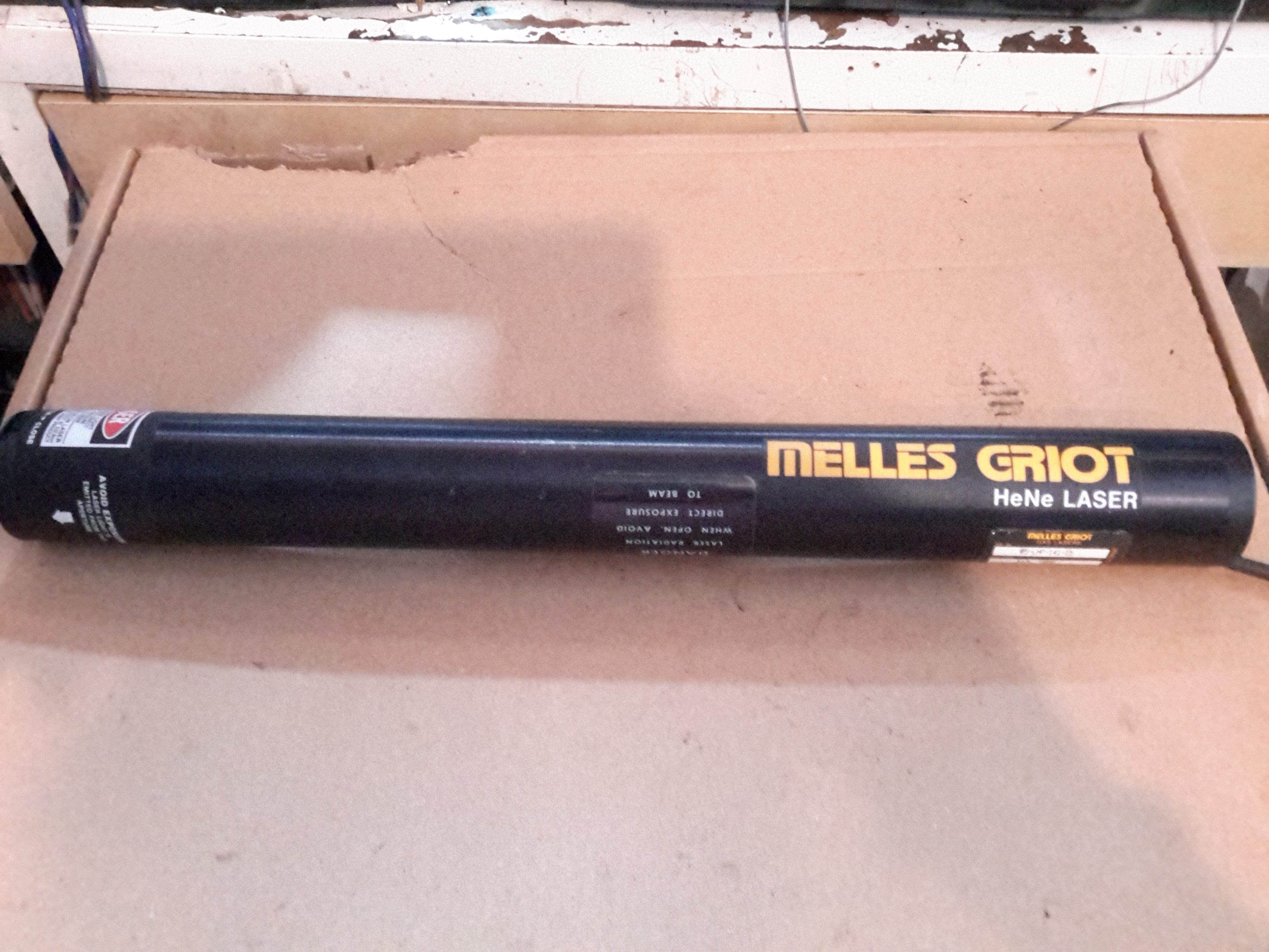
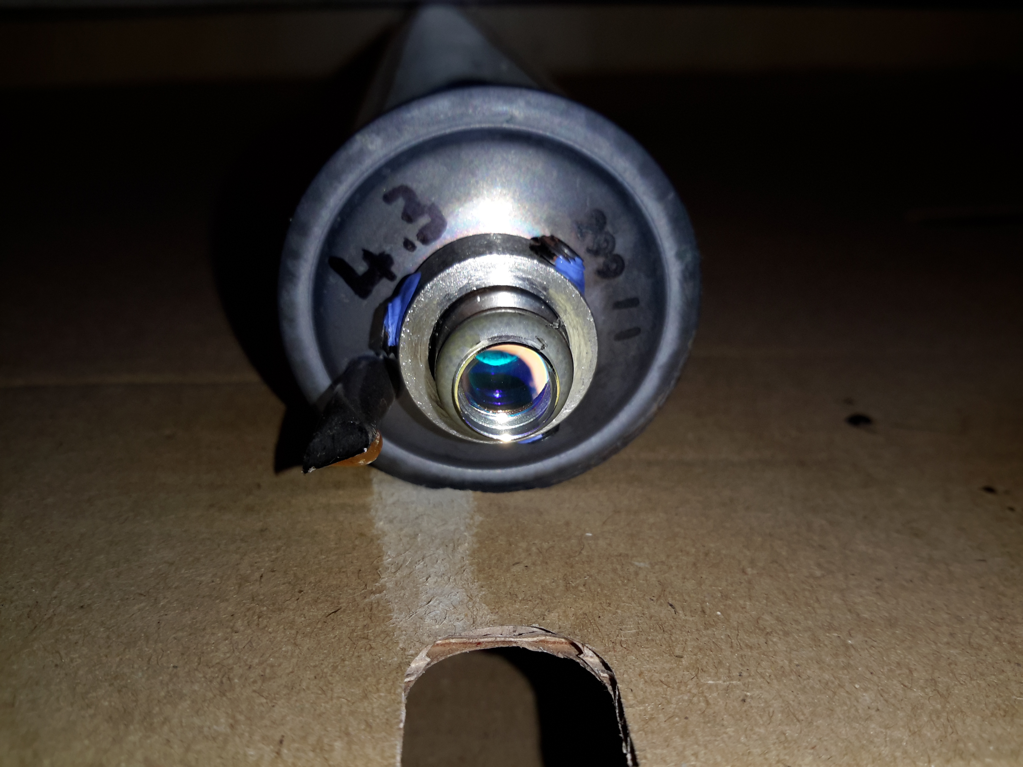
Looking through eBay recently I came across a great deal on some Helium-Neon laser heads from Melles Griot. While definitely not new, these gas lasers are extremely long-lasting & I figured the tubes inside would make a nice addition to my laser collection. Doing some searching on the model number, these heads are rated at an optical output of 4mW, but depending on how much milage is on the tubes, the output may be a bit higher.
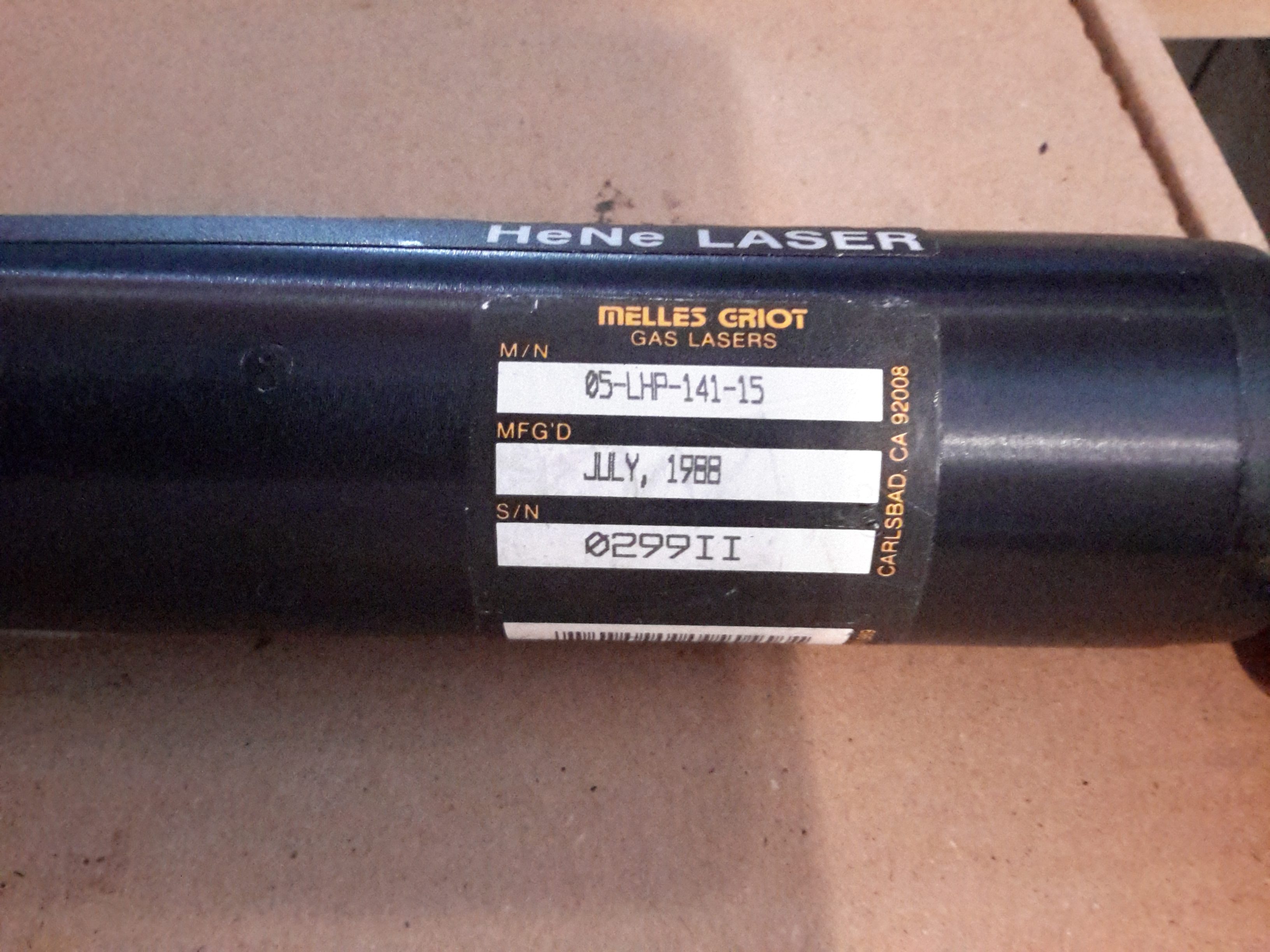
Data Label
I got a pair of the heads, this one was manufactured in July 1988, the other March 1989.
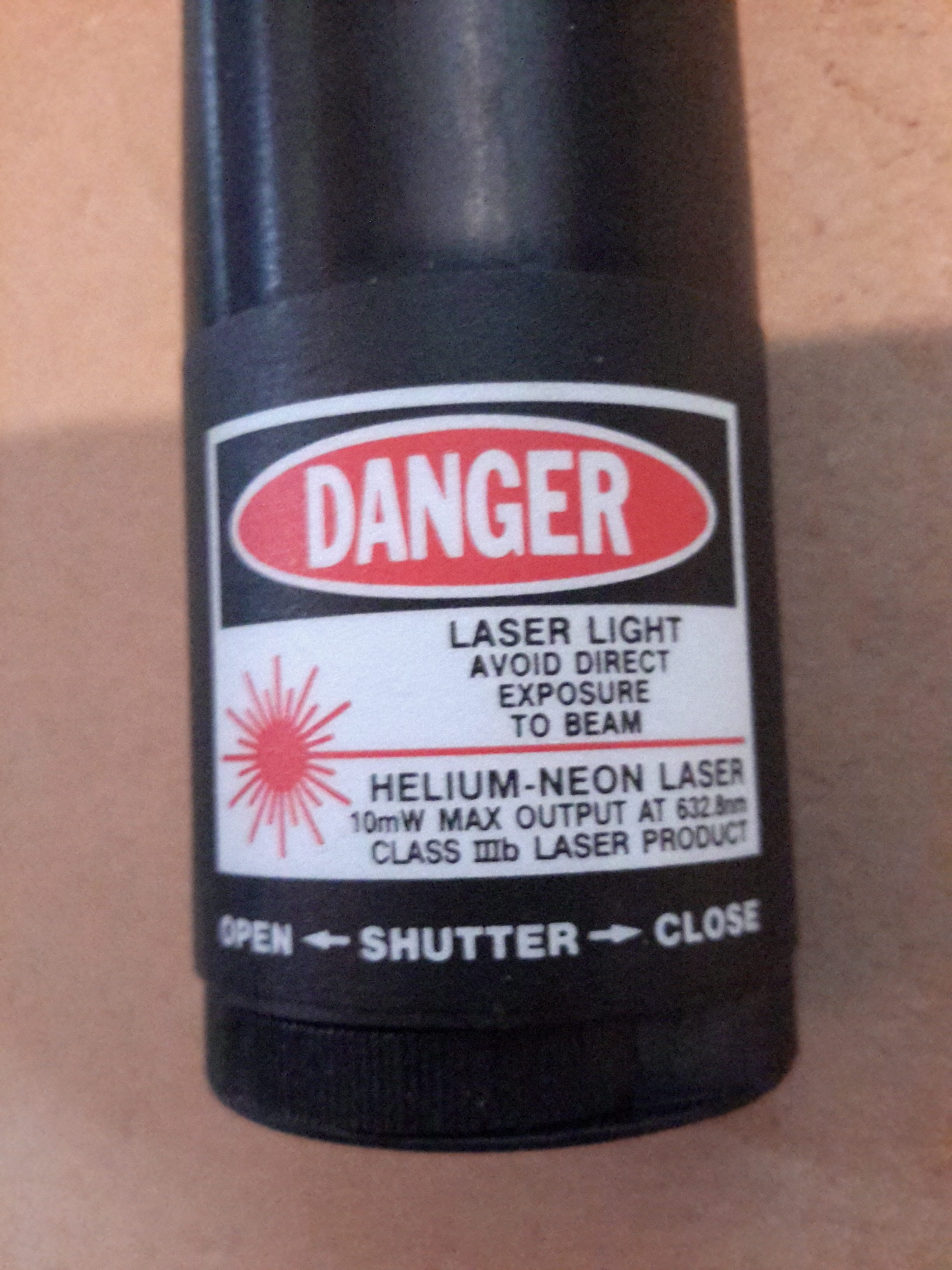
OC End / Classification Label
The OC end of the head has the laser classification label & the beam shutter. Once I’d tested the laser heads to make sure they survived the post intact, I set at extracting the plasma tubes from the aluminium housings.
The end caps are fibre-reinforced plastic & are secured with epoxy resin, so some heating & brute force released the caps from the housing, giving access to the laser tube itself.
Glue Holes
The laser tube is secured in these heads by hot glue – this was squirted into the housing via two rows of holes around the ends. (Some are secured with RTV silicone, which is substantially more difficult to remove).
Copper Tube
I’ve no photos of the actual extraction process as it’s difficult enough as is without at least 5 hands. A heat gun was used to warm up the housing until the glue melted enough to slide the tube out of the housing. Since everything was hot at this stage, a piece of copper tubing (above), was slipped over the OC mirror mount, so I could push the tube out of the housing while the glue was soft. This also protected the mirror from damage while the tube was being removed.
Extracted Tube
After a few minutes of gentle pushing while keeping the housing hot, the tube was released! It’s still pretty well covered in the remains of the hot glue, but this is easily removed once the tube cools down to room temperature with Isopropanol. The line of Kapton tape running down the tube to the cathode end is insulating a start tape electrode, which is supposed to make the laser strike faster on power-up. Instead of being metal though, the electrode appears to be a carbon-loaded plastic tape.
Start Tape & Adhesive
Here’s the HR end of the tube, which also serves as the high voltage anode electrode. The start tape is clipped onto the mirror mount, but all this will be removed.
OC End
The OC end of the laser, where the beam emerges. What I think is the mW rating of the tubes is written on the end cap, probably from when the tubes were manufactured.
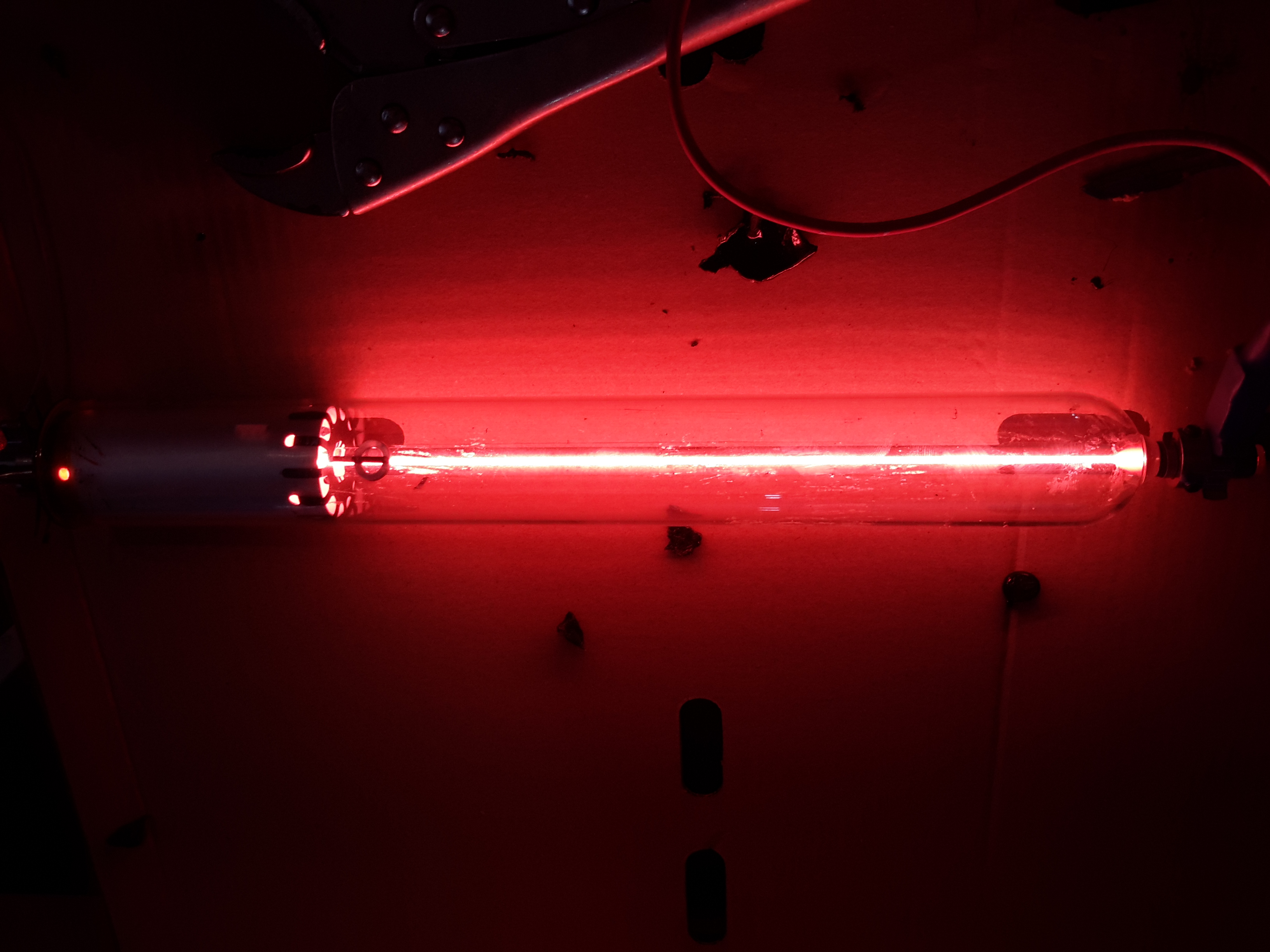
Tube Energized
Applying power from a He-Ne laser PSU confirmed the tube still works!
Going through eBay recently looking for parts for a couple of CRT-based projects, I came across these DC-DC converters.
Apparently rated from 45-390v DC output at 200mA, these should be ideal for driving some of the electrodes (focus, screen, grid) in a CRT.
Above is the top of the board, input voltage header on the left, output voltage adjust in the centre & output voltage header on the right.
This module has a mini-automotive fuse, at 10A for input protection.
On the heatsink is mounted the main switching MOSFET, a RU7088R from Ruichips. This FET is fairly heavily rated at 70v 80A, with 6.5mΩ on-resistance.
PCB Bottom
The bottom of the board has the control components, with a pair of ICs. Unfortunately the numbers have been scrubbed off, so no identification here. The output from the transformer is rectified with a single large SMD diode on the left side of the board.
There’s also plenty of isolation gap between the HV output trace & the low voltage logic side of the circuit, the two being bridged only by a resistive divider for output voltage measurement.
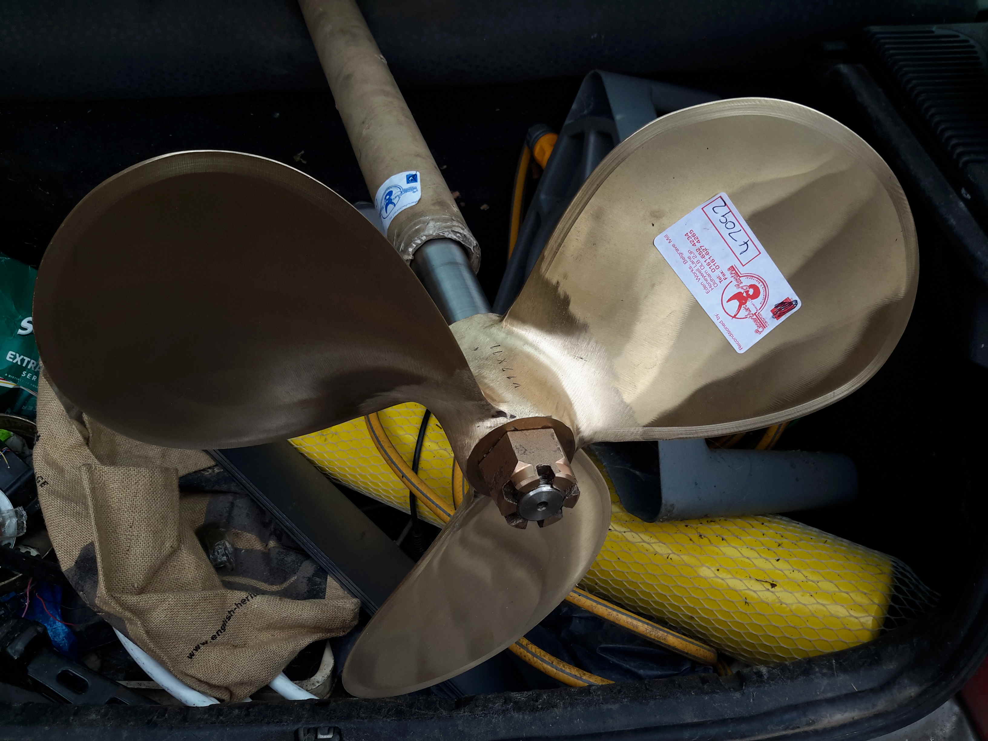
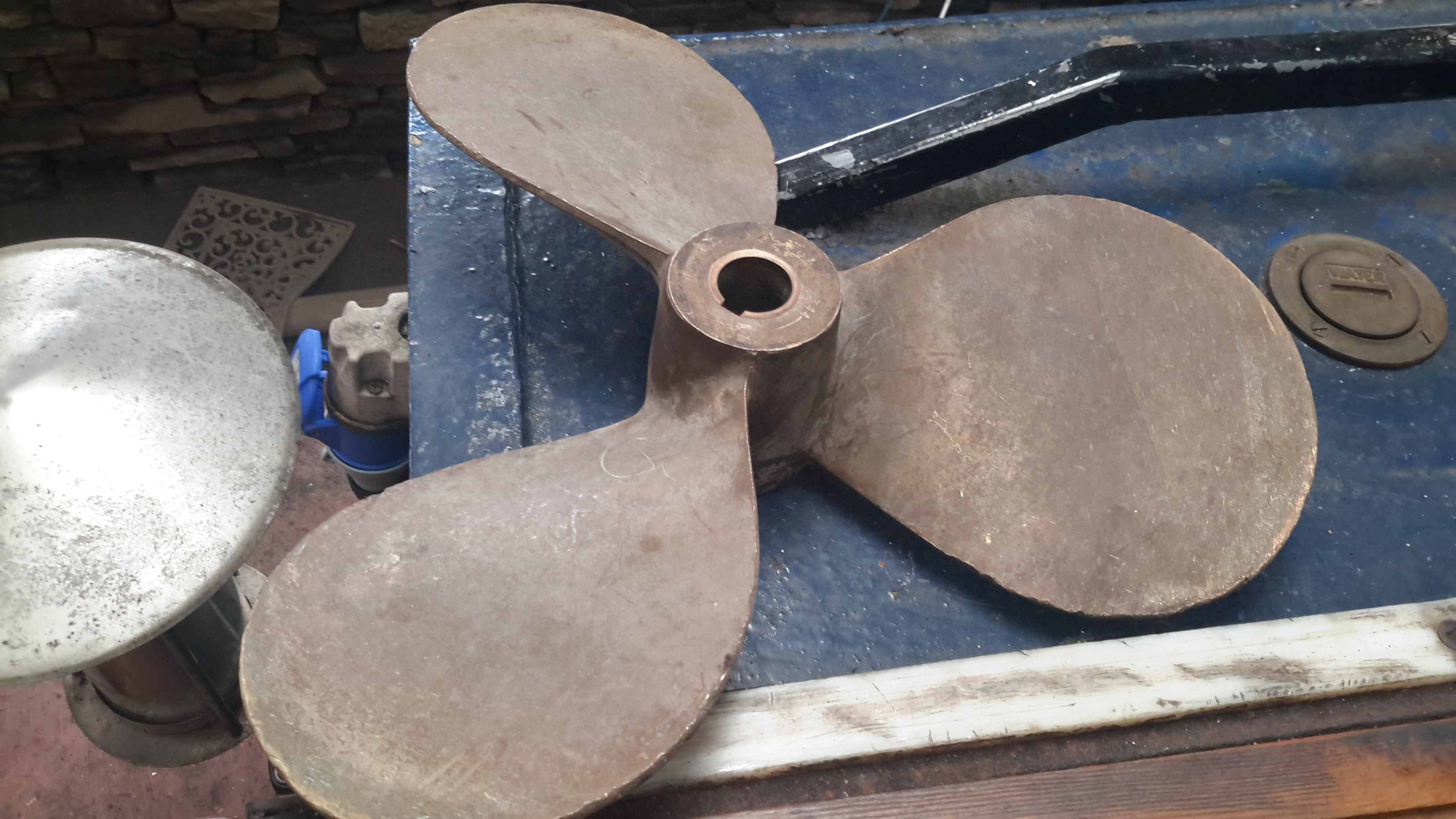
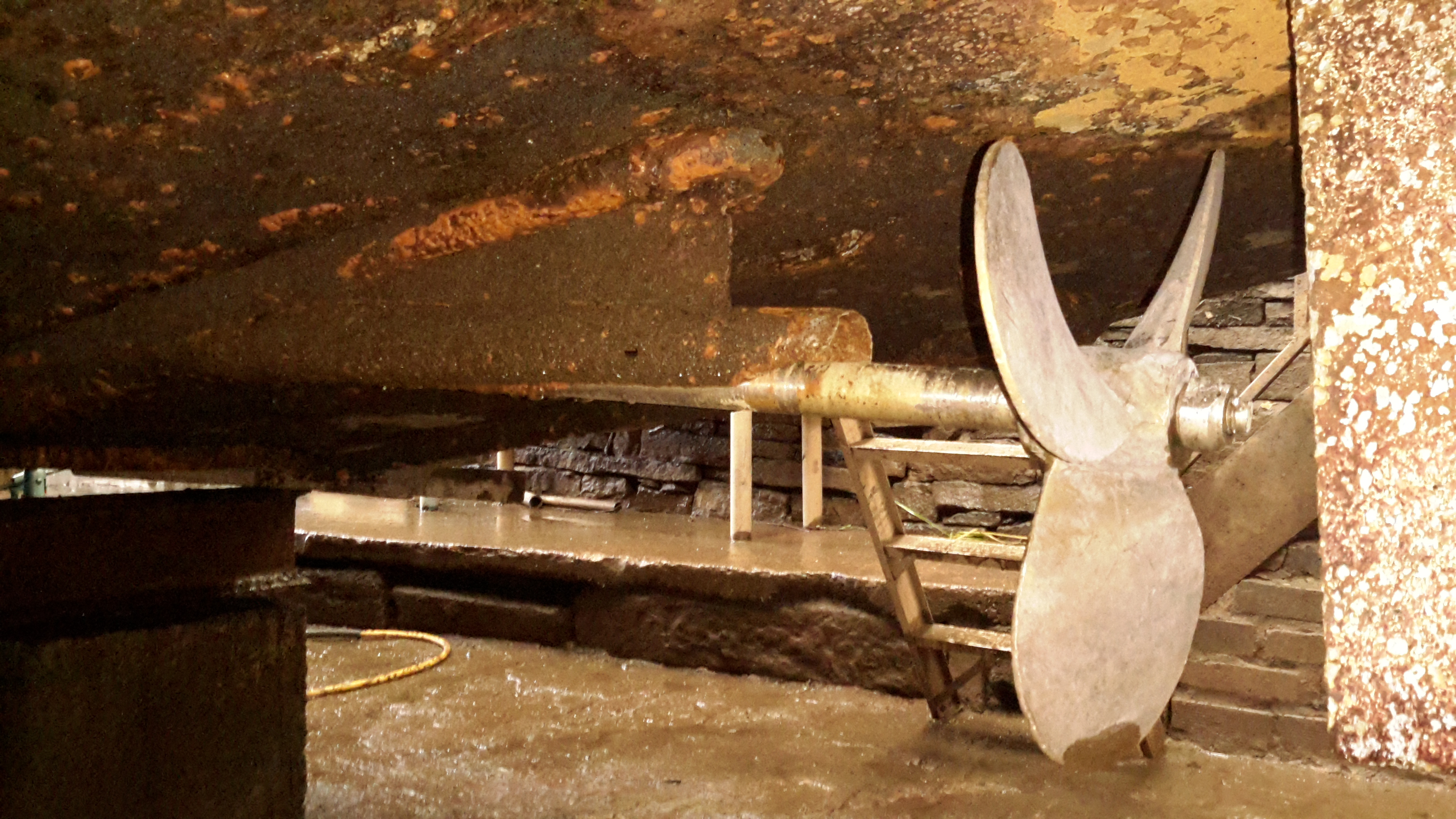
We’re now on the final leg of the jobs to be done on the boat! Above is the new prop & shaft, supplied to us by Crowther Marine over in Royton. To fit our current stern tube & gland, the shaft is the same diamter at 1-3/8″. Unfortunately no 4-blade props were available, so I had to go for a 17×11 left-hand, but with a much larger blade area than the old one.
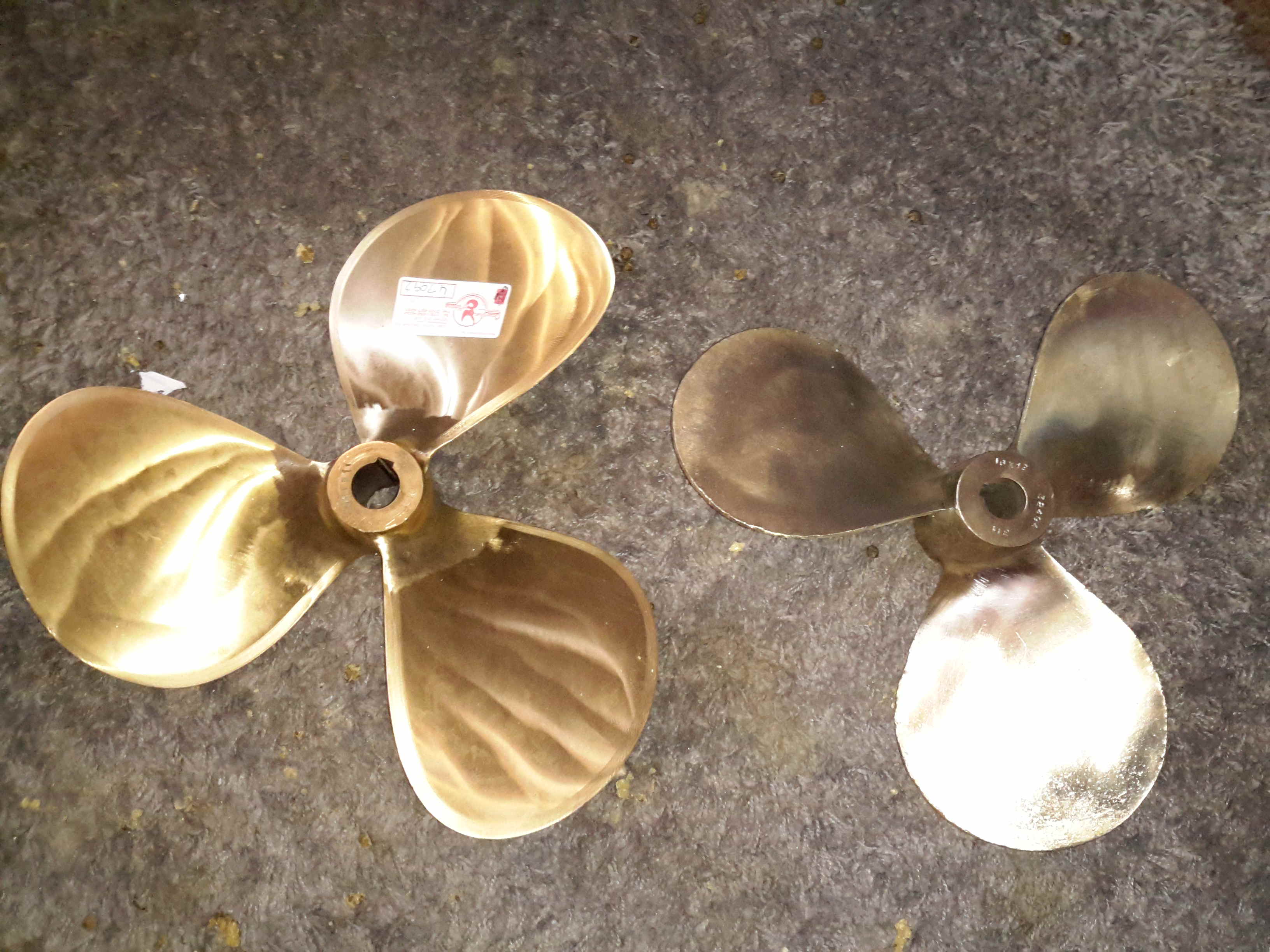
Propellers
Here’s the old prop on the right, with the new one on the left, amazing how different 1 inch of diameter actually looks. The opposite hand of the new prop makes no difference in our case, as I can simply switch the hoses to the hydraulic motor on the shaft to make everything reverse direction.
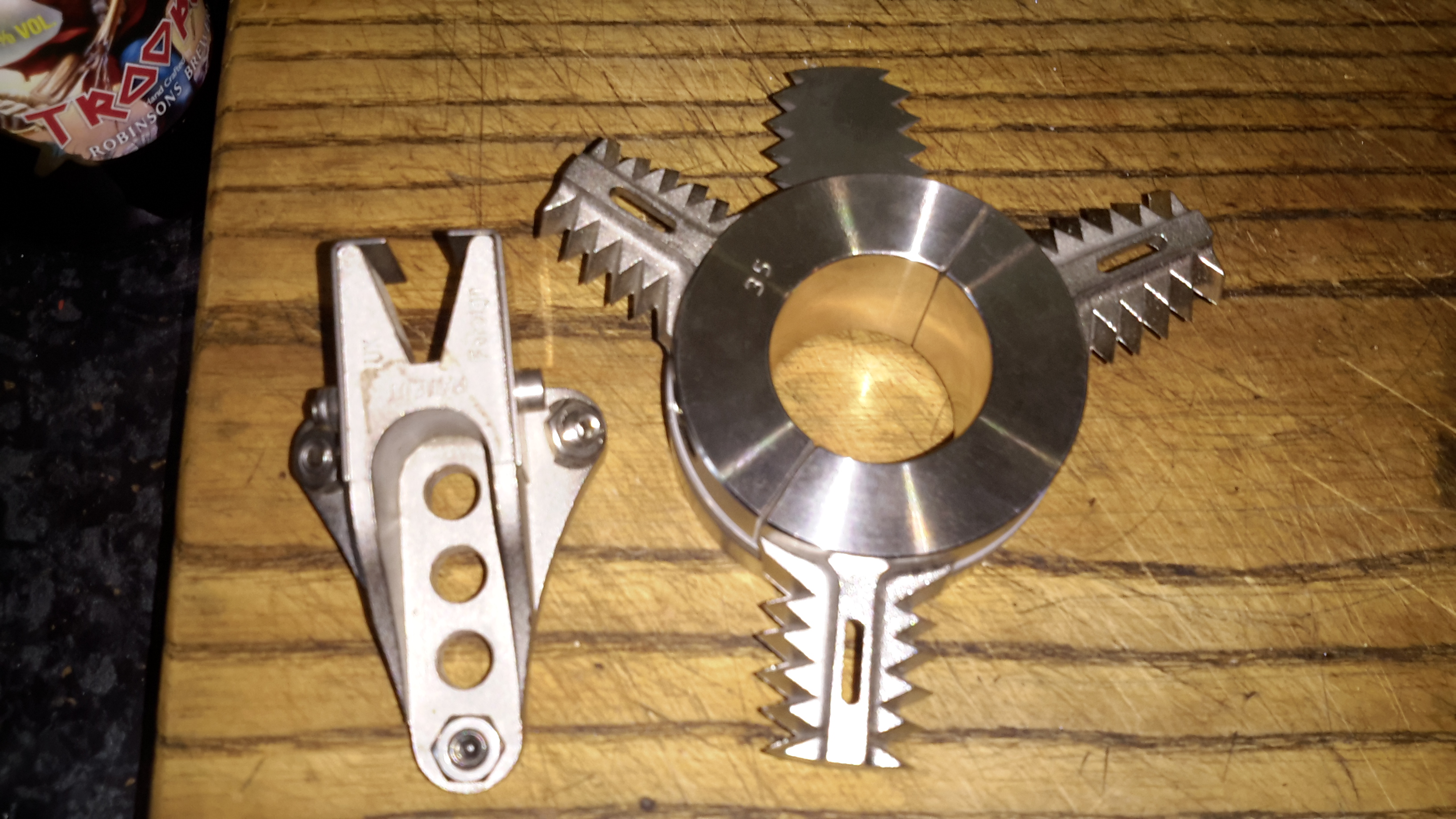
Stripper
Above is the solution to my problem of no weed hatch – a Stripper Rope Cutter from Ambassador Marine. This device has some seriously viciously sharp cutting teeth to help clear any fouling from the prop in operation. Only time will tell if it’s effective at allowing me to stay out of the canal manually removing the crap!
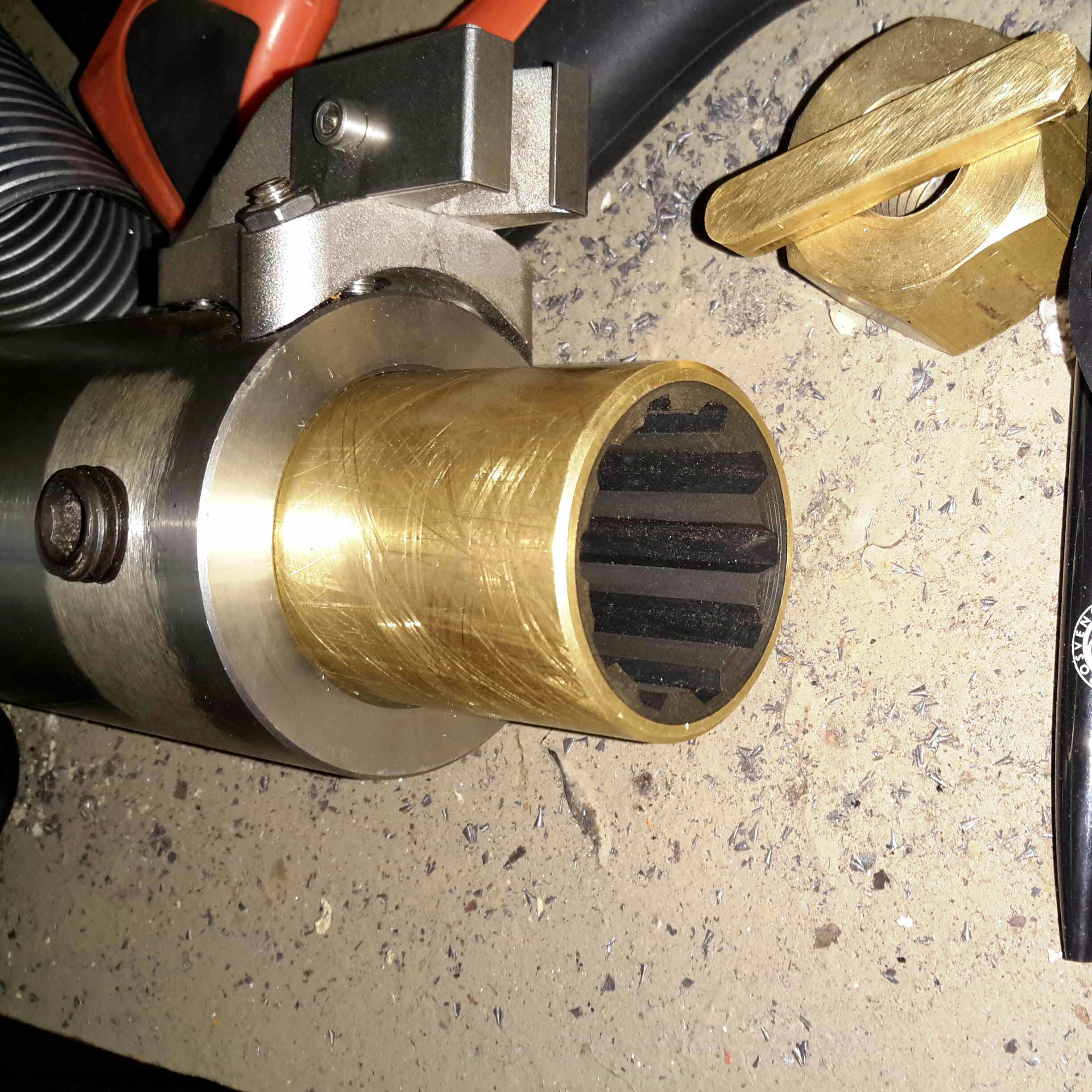
Cutless Bearing
We finally got the bearing mount finished, by S Brown Engineering in Stockport. This is made from Stainless steel to stop the bearing corroding in place & becoming a real arse to replace. Set screws are fitted to make sure the bearing doesn’t move in service.
Attached to the side of the bearing housing is the fixed blade mounting for the Stripper Rope Cutter.
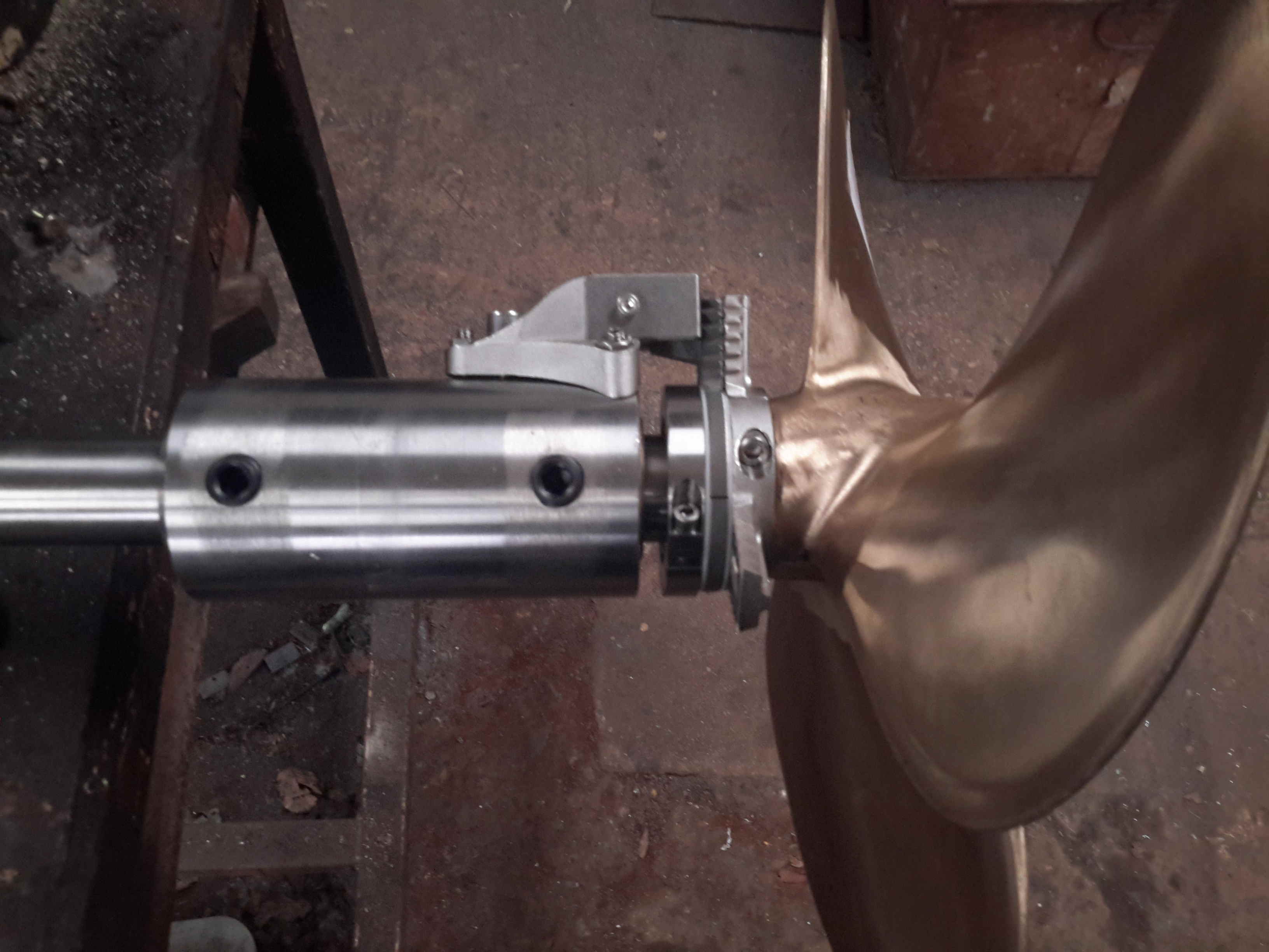
Bearing Test Fit
Above is everything fitted to the shaft for a test before the gear went into it’s home in the stern tube. The Stripper mounts behind the prop, clamped to the shaft. The 3 moving blades move against the fixed blade like a mechanised pair of scissors.
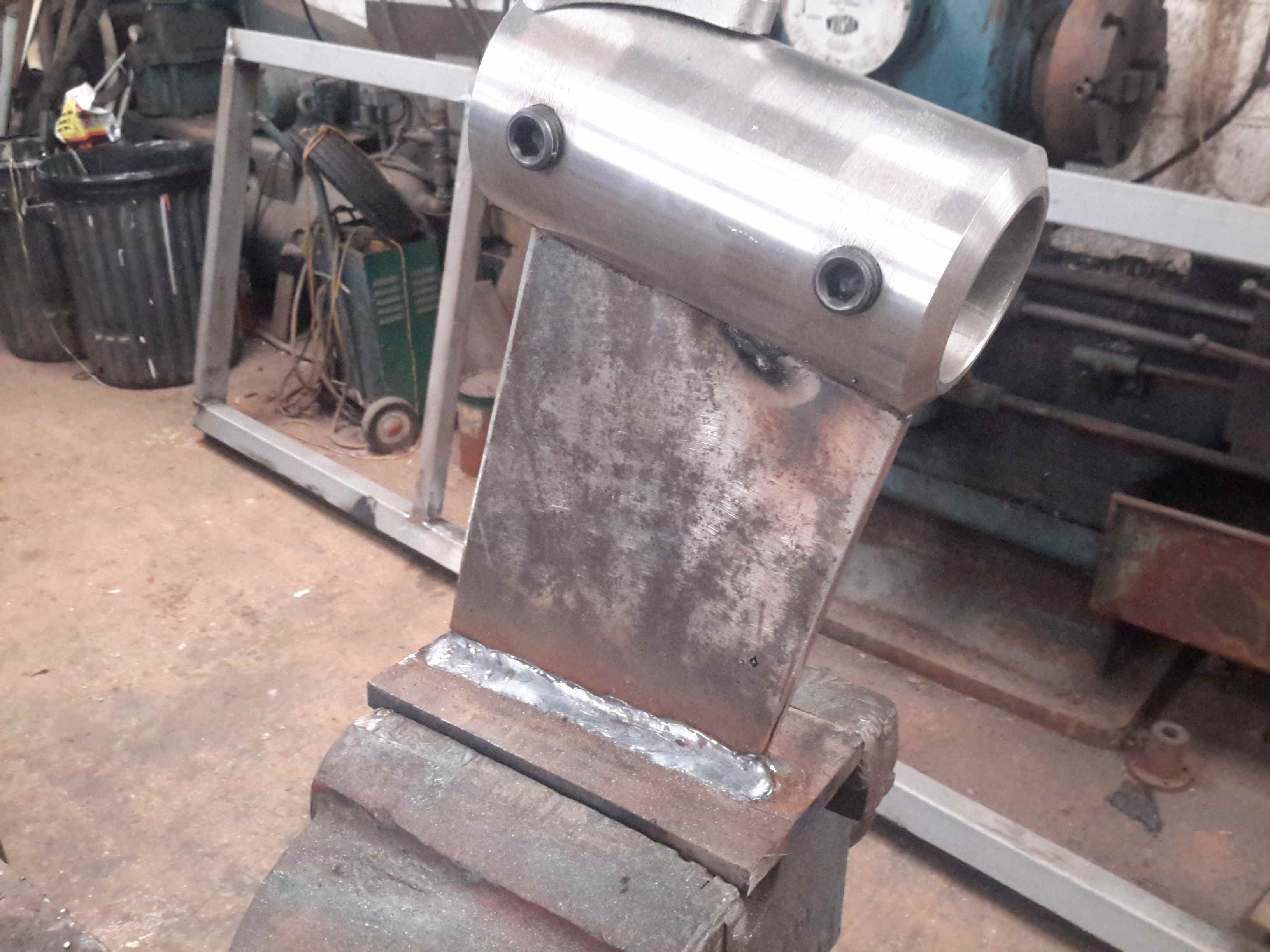
Bearing Strut Welding
10mm steel plate has been used to make the strut for the bearing tube, welded together. In the case of the joint between the stainless tube & the carbon steel strut, special welding rods were needed, at the price of £2 a rod! Using mild steel rods to weld stainless could result in cracking of the welds. Not a good thing on a prop shaft support bearing.
Sand Blasted Hull
Most of the old tube has been cut away to make room for the new bearings, and the bottom of the hull has been sand-blasted ready for welding.
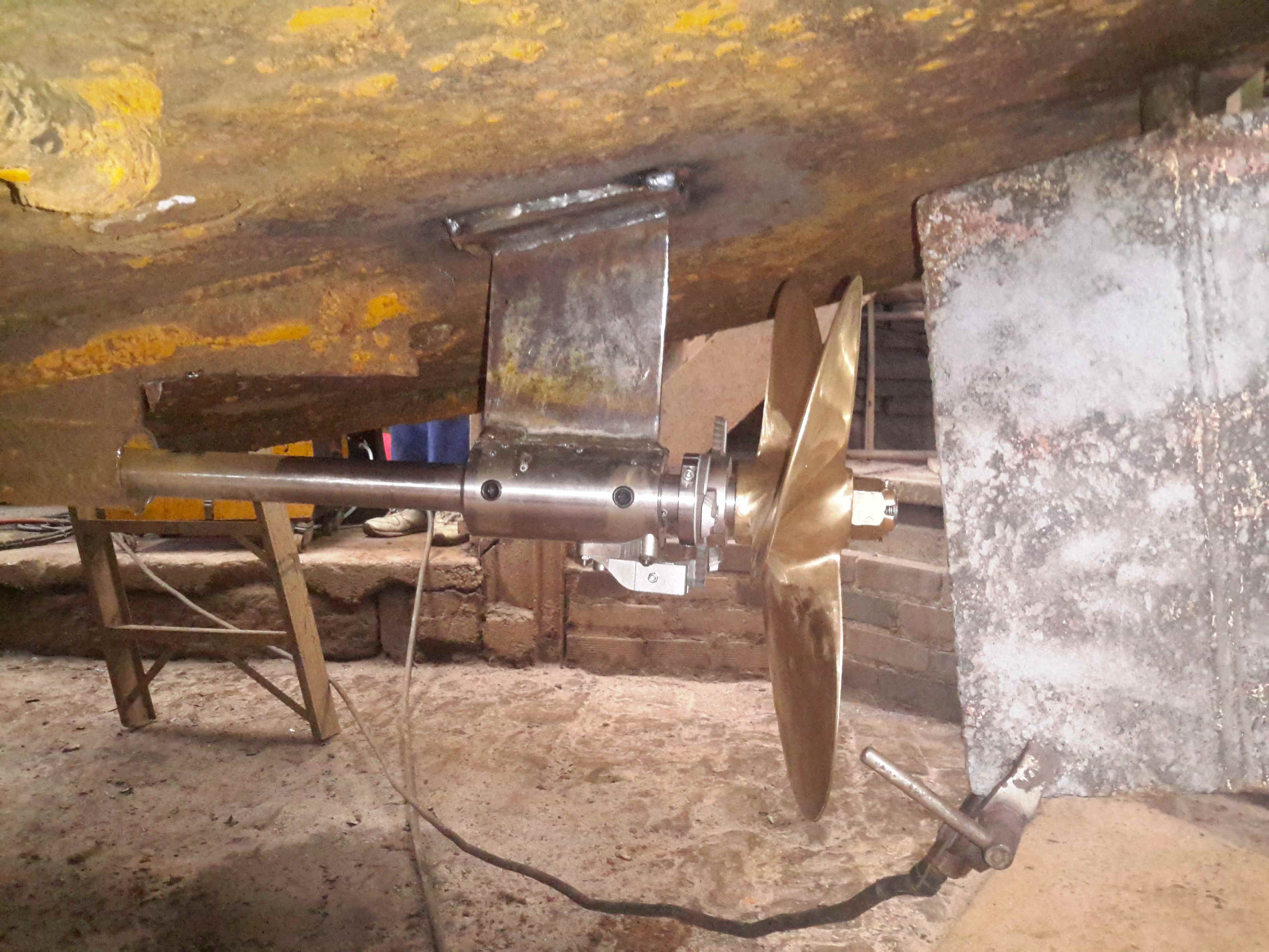
Running Gear Mounted
The bearing mount is welded to the hull, the Stripper & the prop are fitted to the end of the shaft. There’s 1.5″ of clearance from the blade tips to the hull plating. The rudder has about an inch of clearance to the end of the shaft.
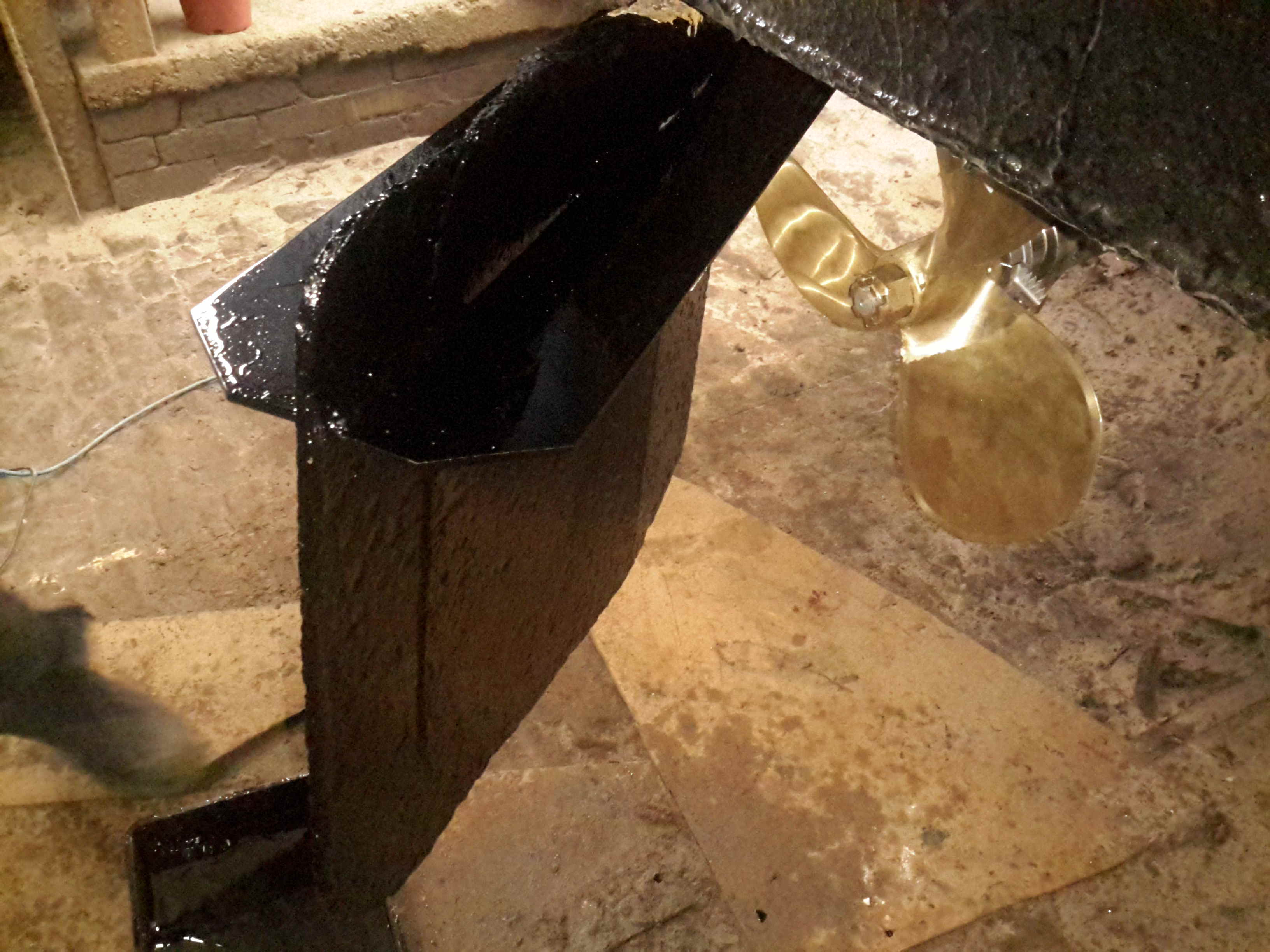
Rudder Fence
To help keep the prop wash down, directing more of the force into moving the vessel rather than creating a nice rooster tail, a pair of plates has been welded onto the rudder. These also provide a handy step should someone fall in ;).
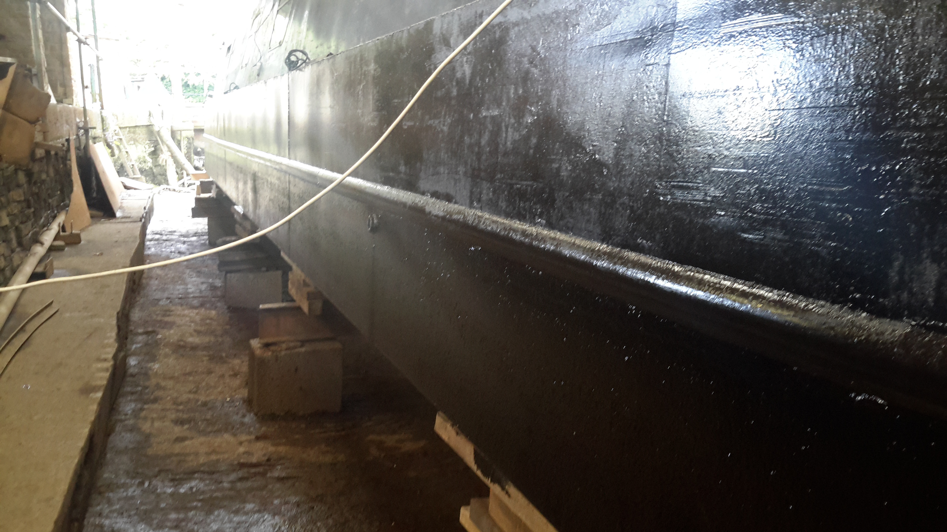
Things are coming along nicely with this year’s drydock operations.
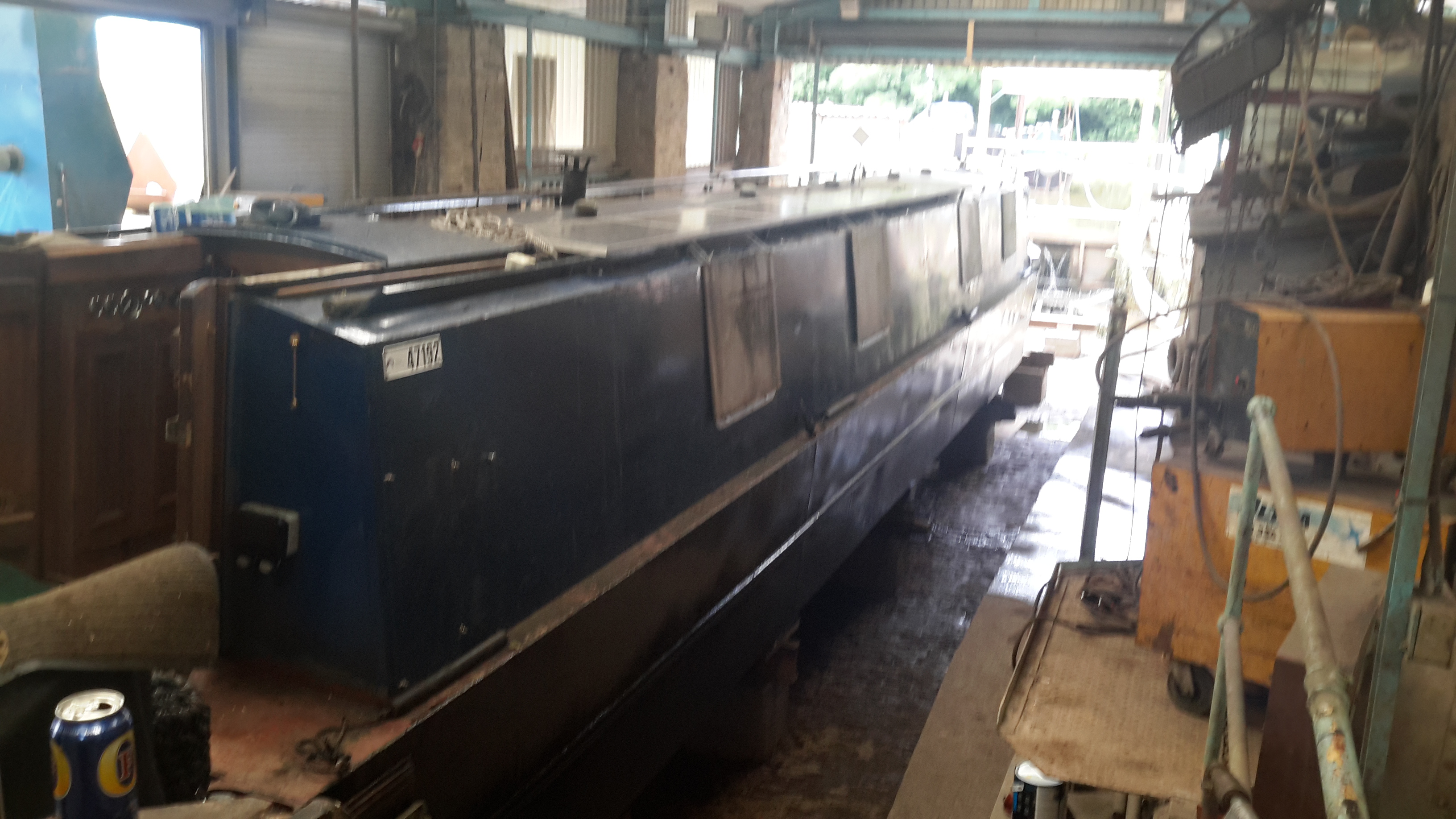
Blacking – Second Coat
Shes looking much better, the second coat of bitumen blacking is on, we’re going to continue at a coat a day until we’re due back in the water.
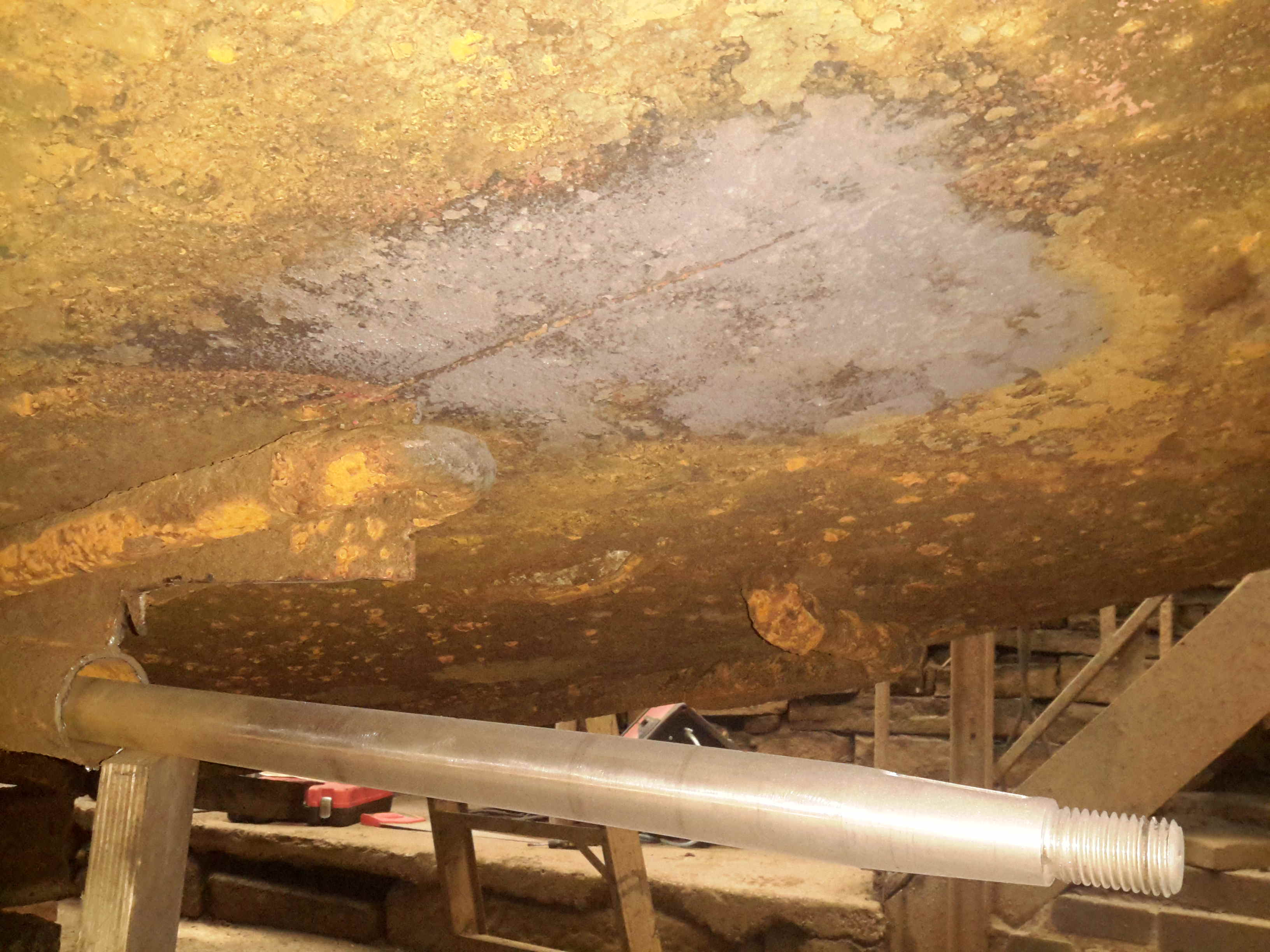
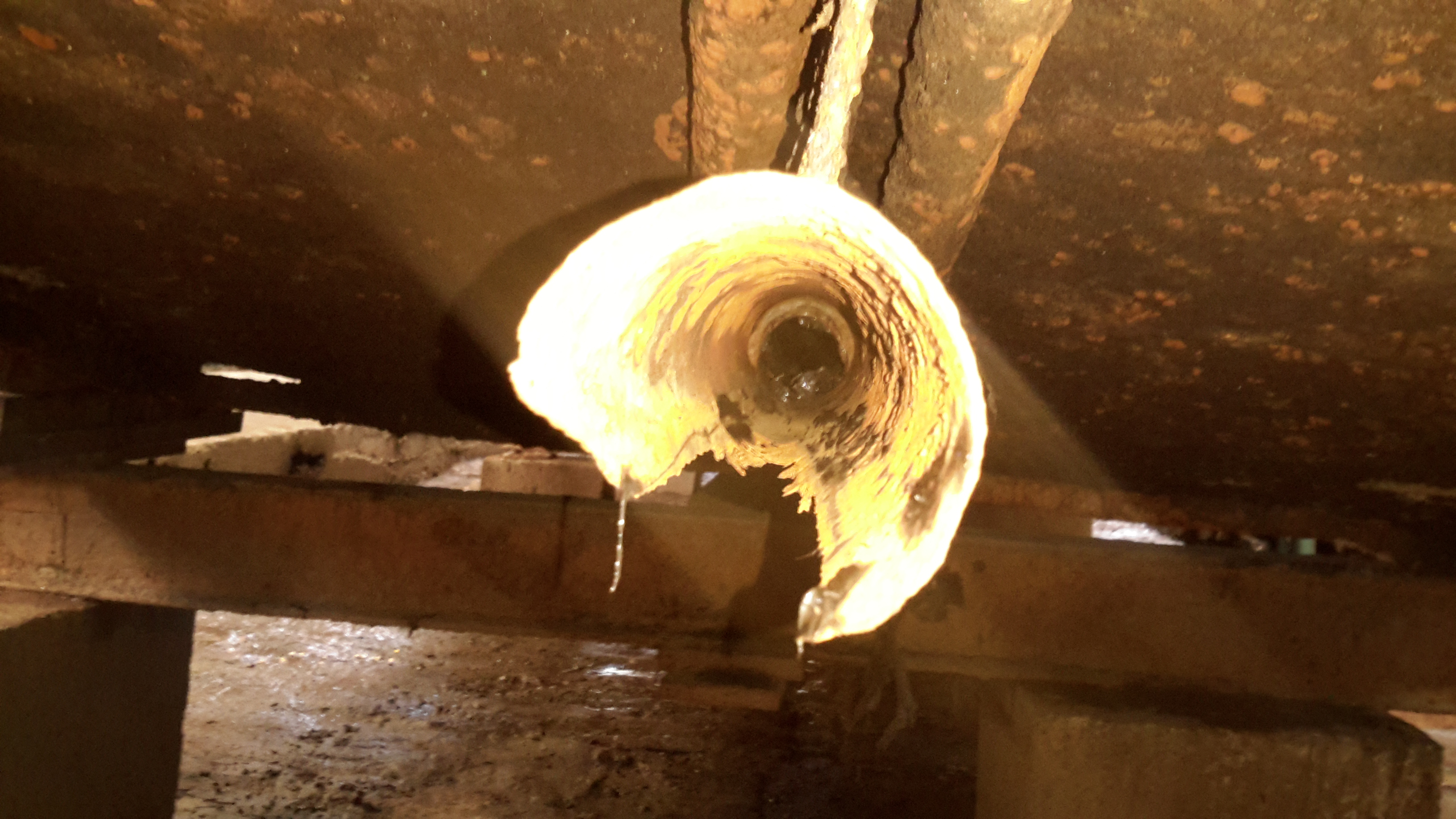
Shaft Tube Damage
I’ve now removed the shaft from the stern tube to gain better access, now the full extent of the damage to the tube can be seen. There’s nothing left at all of the old bearing, which on this boat was simply a nylon bushing pressed into the end of the tube. (I knew it was crap the last time we were out, but ran out of time to get a fix done).
The stainless shaft, having lost it’s support bearing at some point, has been running on the inside of the steel tube, and has neatly chewed straight through it.
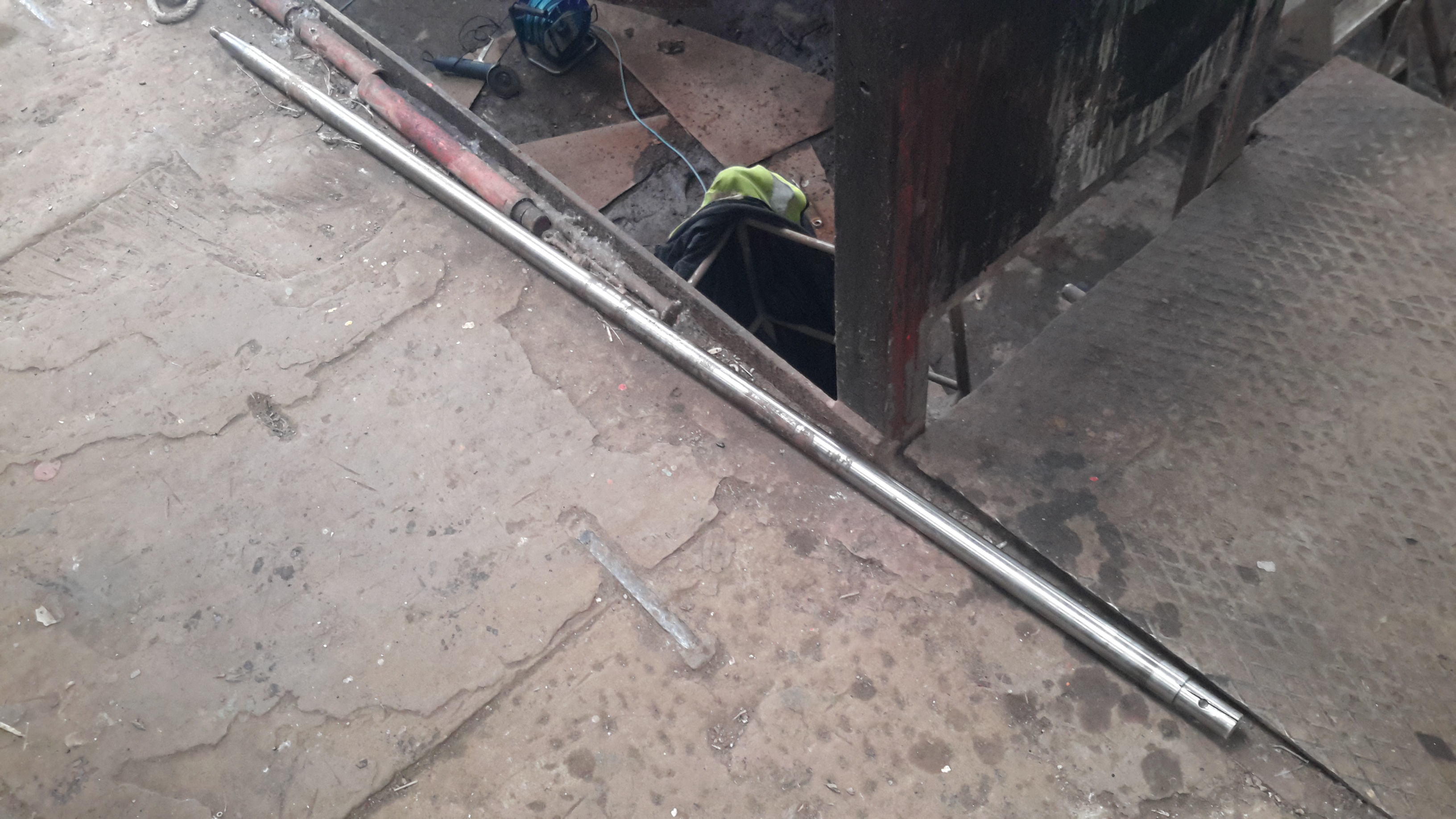
Prop Shaft
Here’s the prop shaft removed from the boat – possibly the longest shaft I’ve ever seen on a narrowboat at 6′ 2″. Unfortunately, the fact that it lost the bearing has also damaged the shaft itself, this will have to be replaced.
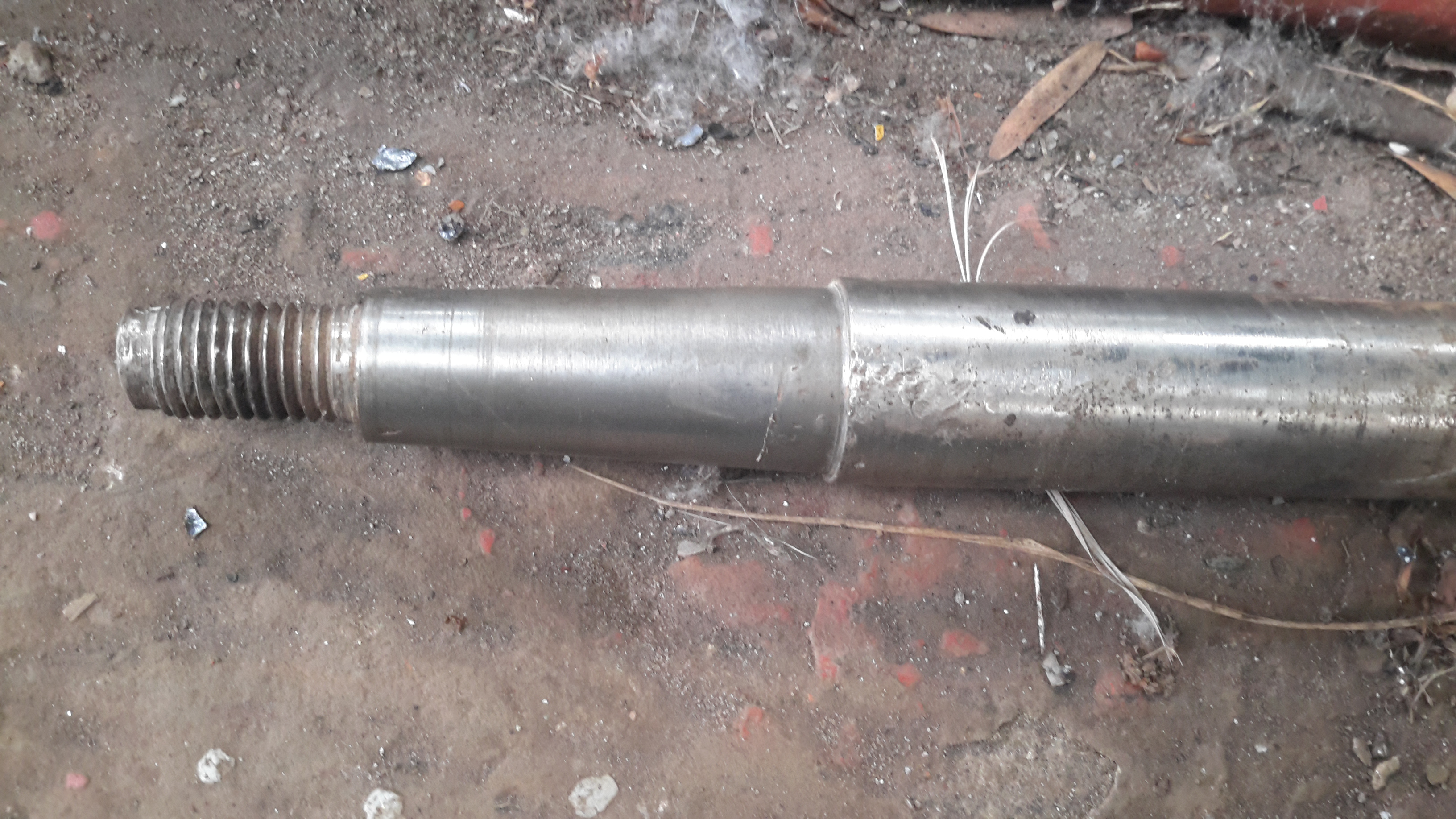
Prop Taper
Here’s the end of the shaft that would run in the end bearing, it’s badly scored & fitting a new bearing to this shaft would cause failure very quickly. The taper on the end isn’t much better, and a loose fit in the prop has done some damage there also.
Old Prop
Here’s the old prop – a 16×12 that was only fitted a few years ago. This will be replaced with a new 4-blade prop, as this one is far too small for the size of the boat & installed power. Installing a larger diameter prop isn’t possible due to clearance from the swim, so I’ll have to get a more steeply pitched prop, with 4-blades for increased contact area with the water.
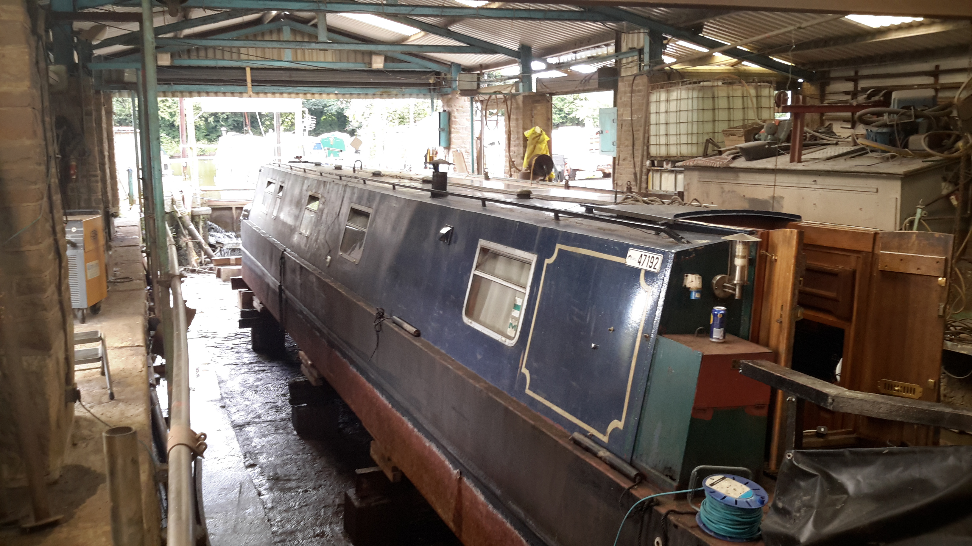
It’s that time again, so the boat is out of the water for it’s 3-yearly maintenance. Some things over the past few months have been bugging me, namely a pronounced vibration in the running gear while underway. (Issue was easy to spot here!).
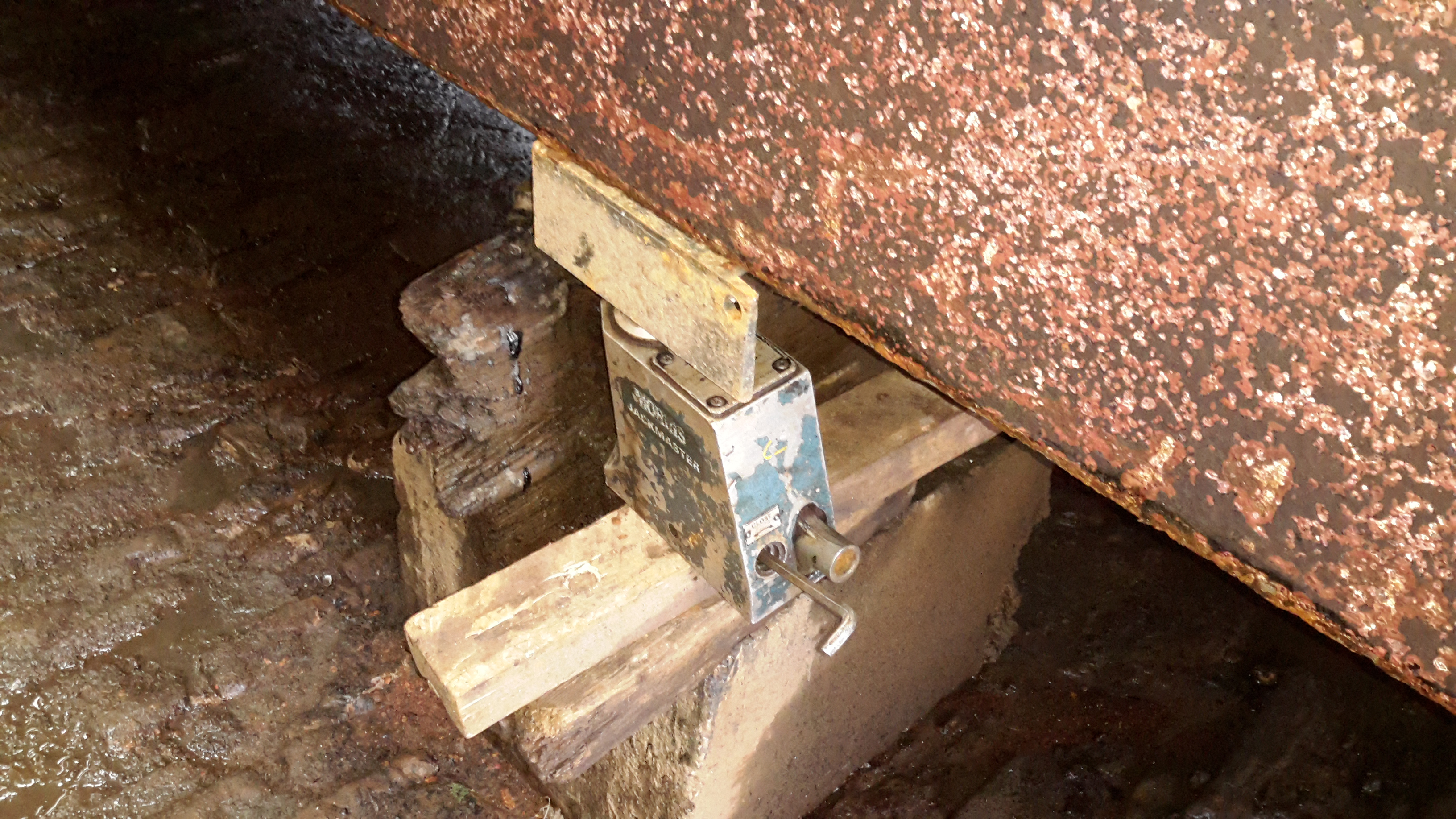
10-Ton Jack
nb Tanya Louise being a very odd vessel, she has quite a significant keel, so once the dock was drained, some manual jacking was required to get her level on the blocks. Without this extra work there is such a pronounced heel that it’s impossible to do anything on board.
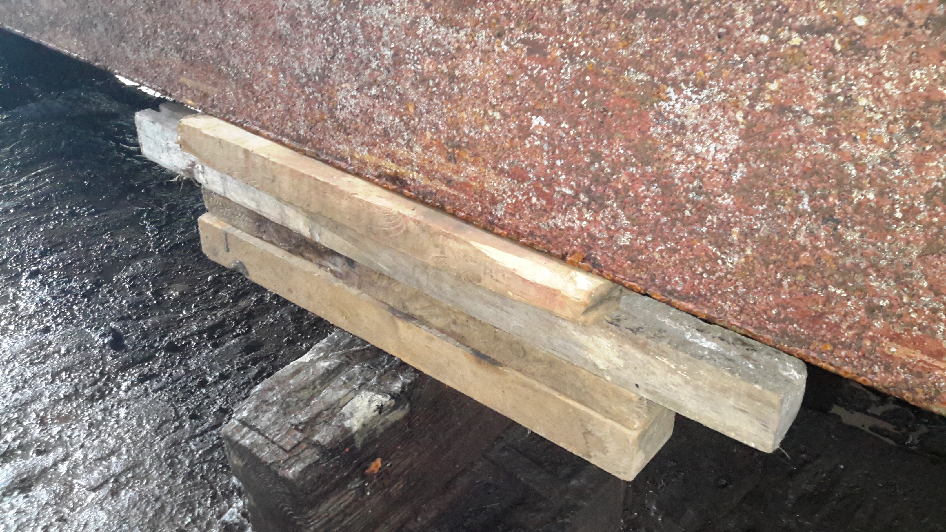
Chocks
On the opposite side, wooded blocks are placed for the bottom of the hull to rest against. Jacking up a 58-ft 25-ton boat by hand onto some timbers was nerve-wracking to say the very least!
The bottom of the hull has already been jet-washed to remove 3-year’s worth of slime, weed growth & the old blacking. First job is to get a fresh coat of paint on.
Running Gear
Looking under the hull shows the reason for the high level of vibration – the prop shaft has actually *worn through* the bearing & stern tube, to the extent that there’s not much left of the assembly! The only thing holding the shaft in place at this stage is the stuffing box inside the boat & the shaft coupling to the hydraulic motor.
, stern tube,
A replacement standard-issue Cutless bearing will be fitted, after the remains of the old tube are cut back to make room. To facilitate mounting the bearing, a custom stainless P bracket is being made at a local engineers, for me to weld onto the bottom of the hull.
(Surprised we didn’t lose the shaft, lucky that I kept pestering to get her out of the water!).
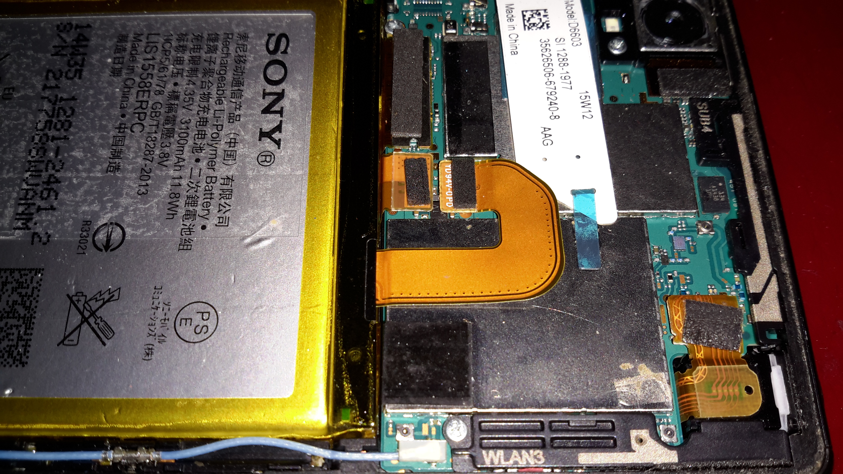
Recently my phone decided it was going to die a battery-related death, and having not found much useful information on the Great Google, (all the information I could find, was hinting at many issues from firmware to a faulty motherboard, nobody seems to have actually done any investigation into similar issues), I decided to dig into the phone to try & repair the problem.
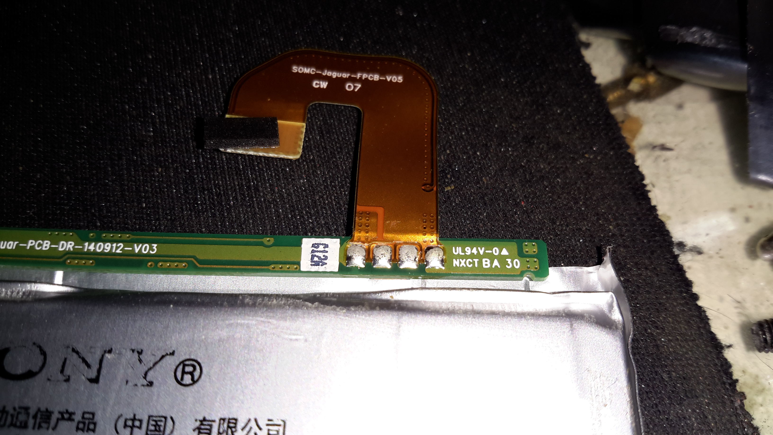
Broken Flex
The phone would work correctly for a while, then with the slightest movement or knock, would spontaneously switch off, and not turn back on without being whacked on a hard surface.
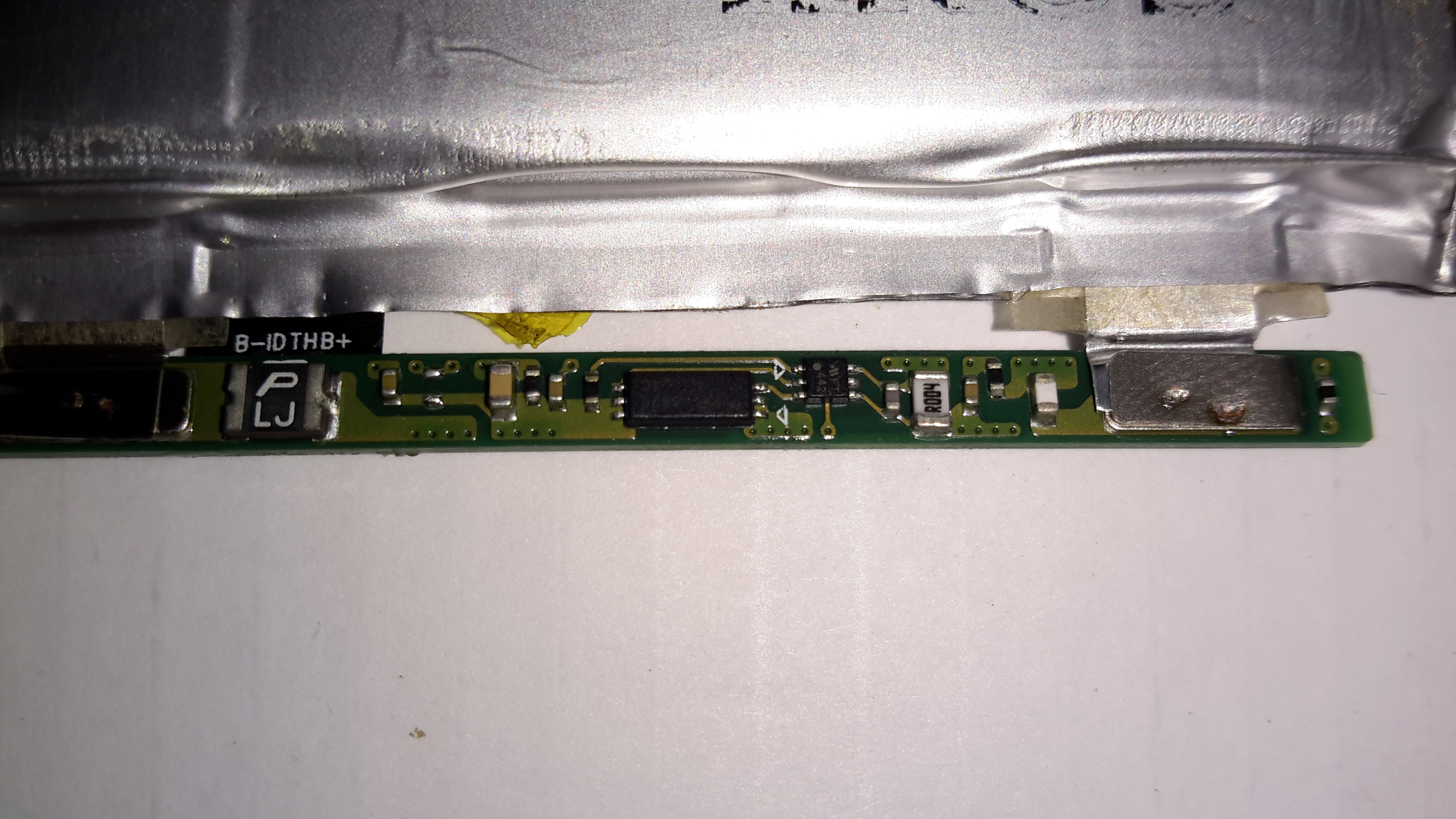
This symptom pointed me at a power connection problem. After removing the back of the phone (glass & heavily glued in place, so an awkward process), This was what I was presented with on the cell flex PCB.
In the above photo, the positive connection to the flex is fractured just after the solder joint with the BMS board.
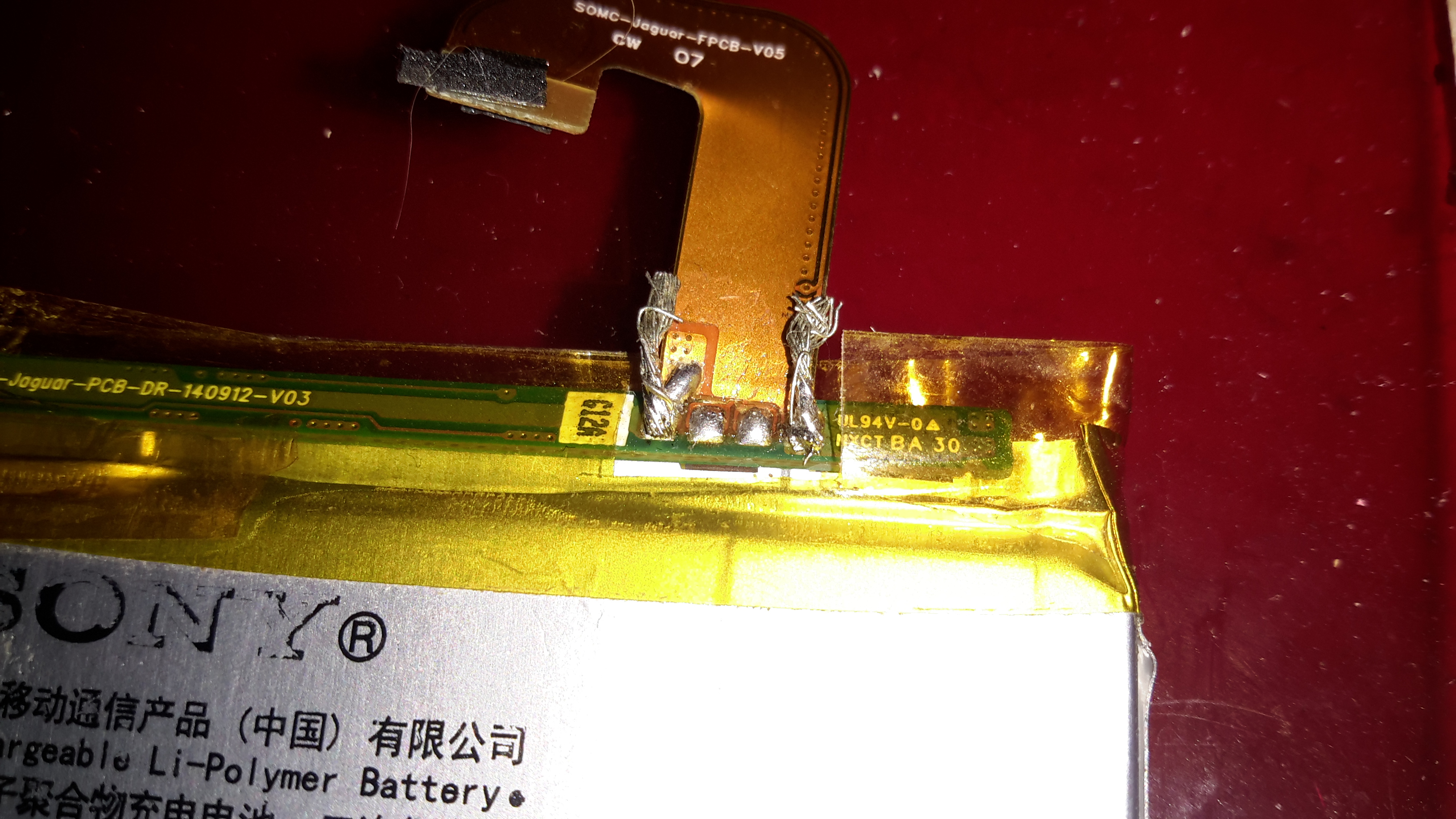
Flex Repair
I managed to scrape some of the insulation off the flex PCB & solder a jumper on to restore power. Unfortunately, this repair generated another fault, where the battery level was always shown at 50%, and plugging into a USB supply wouldn’t charge the phone. The other two pins on the cell are for communication & temperature sensing, clearly one of these traces was also broken in the flex.
The above photo has a pair of very small wire tails as well, for connecting an external charger.
50% Battery
Here’s a screenshot of the phone with the original cell, even though it’s at about 4.15v (virtually fully charged). The battery management is having trouble talking to the phone, so for safety reasons, the charging logic refuses point-blank to charge the thing up.
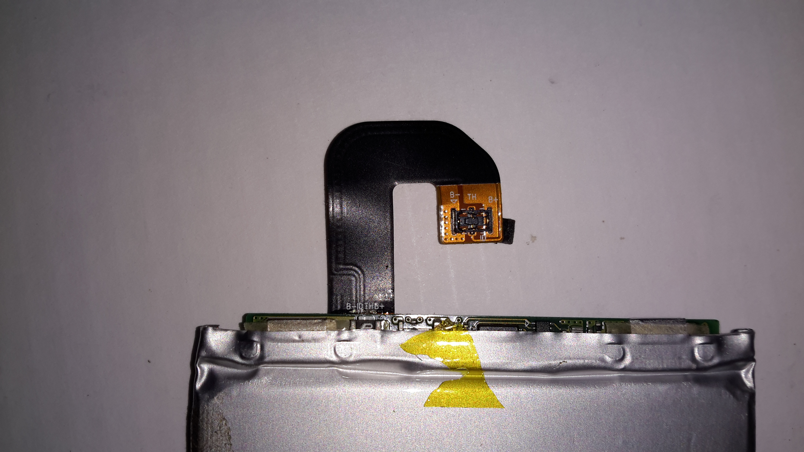
Flex Cable
The connector on the cell & phone motherboard is absolutely tiny, so I didn’t fancy attempting to solder on any bridge wires to try & bypass the broken flex.
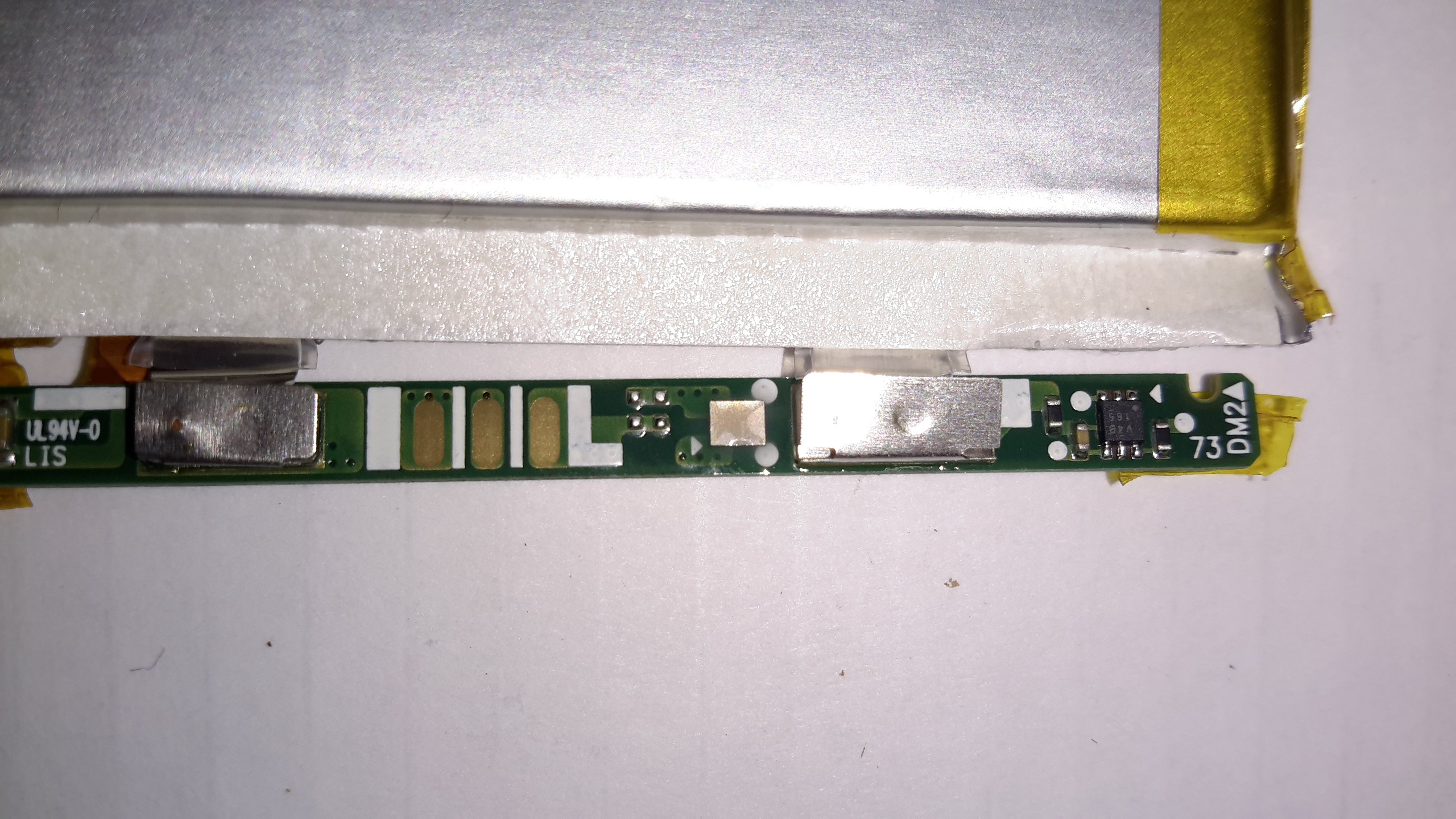
Battery BMS
The cell BMS has some intelligence on board, besides the usual over-current, over-charge & under-charge protection. The very small IC on the right has a Microchip logo, and the marking FT442, but I was unable to dig up any datasheets. The current sense resistor is directly connected to this IC, along with the main power FET to the left.
BMS Reverse
On the other side of the BMS board is another IC, again unidentifiable, and what looks like a bare-die, or CSP IC.
At this stage I figured the only way forward was to buy a new battery, eBay turned one up for less than £5. Above is the new battery fitted to the phone, datestamped 2014, so definitely old stock.
100% Battery
Booting the phone with the new battery quickly lets me know the fix worked, with a 100% reading & the ability to again charge properly!
As some will know, I’ve just returned this week from Download Festival, after the yearly pilgrimage to the Mecca of Metal! Click the image below to take a look at the photo albums!
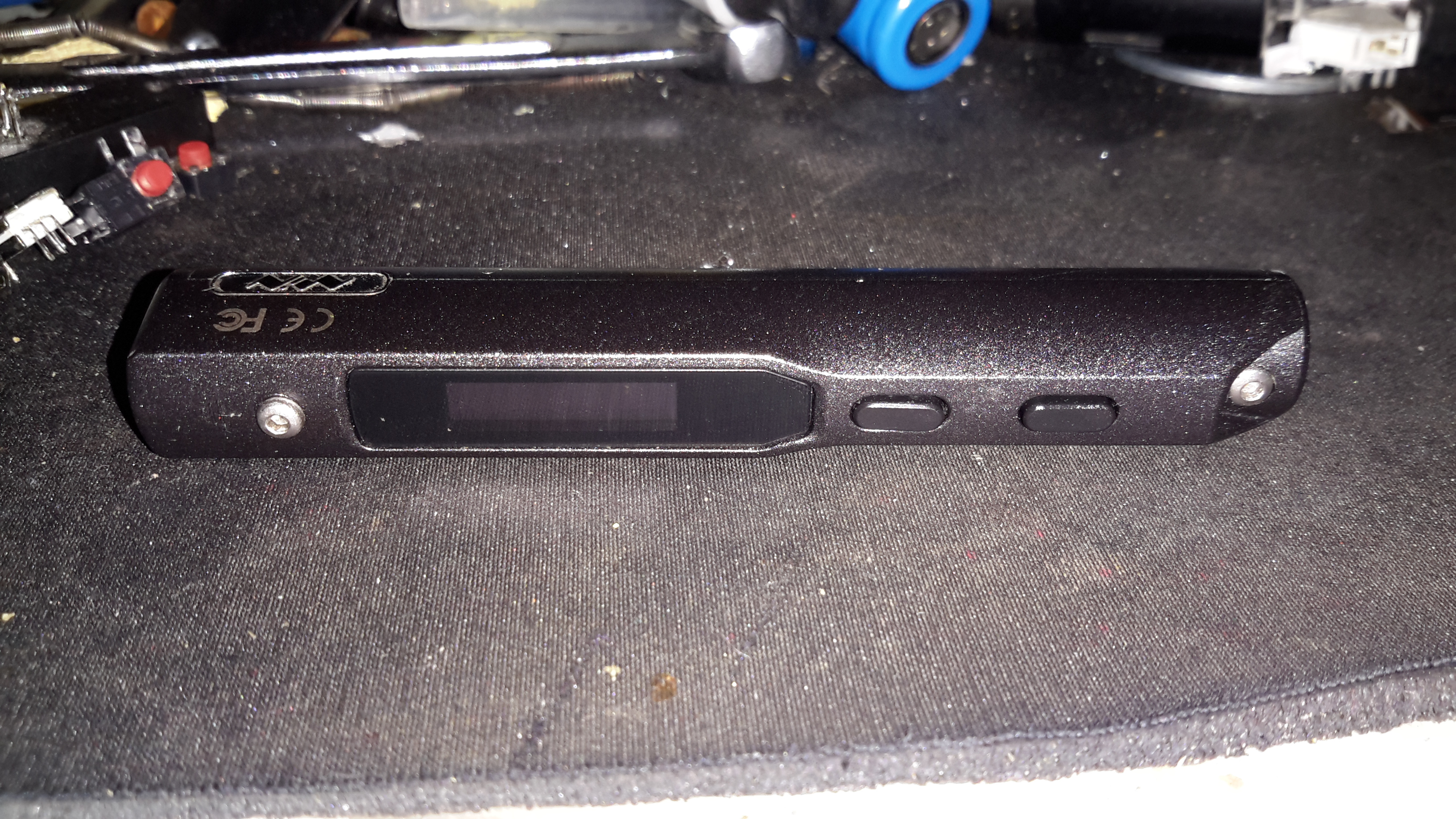
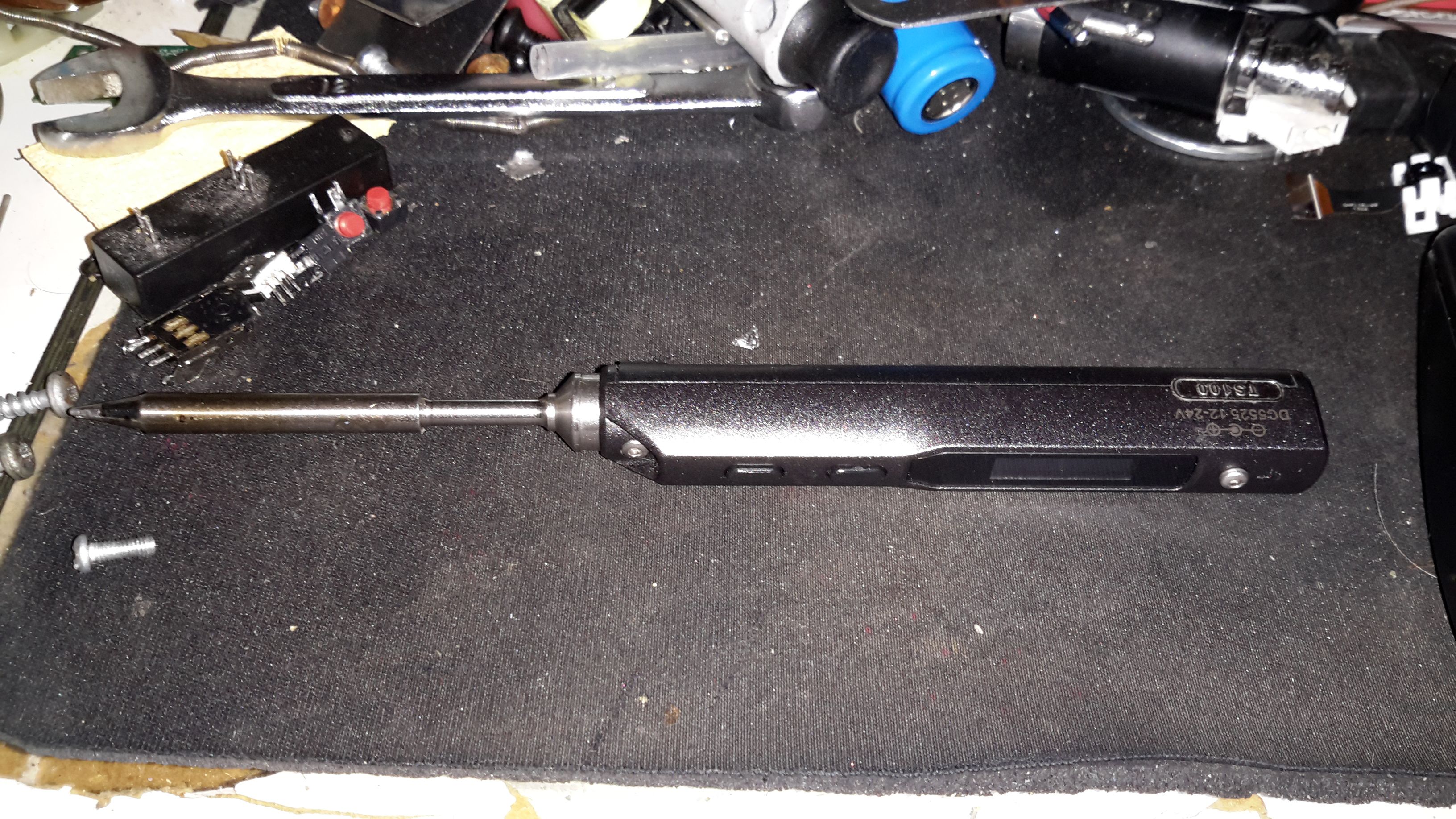
When I ordered the tiny USB soldering iron, I decided a proper iron upgrade would be a good idea. Looking around for something that didn’t require AC mains power turned up the TS100, a Chinese design, that unusually is actually very good! Above is the handle itself, with it’s small OLED display & two operation buttons.
This iron is controlled by a STM32 ARM microcontroller, the firmware & schematics are completely open-source.
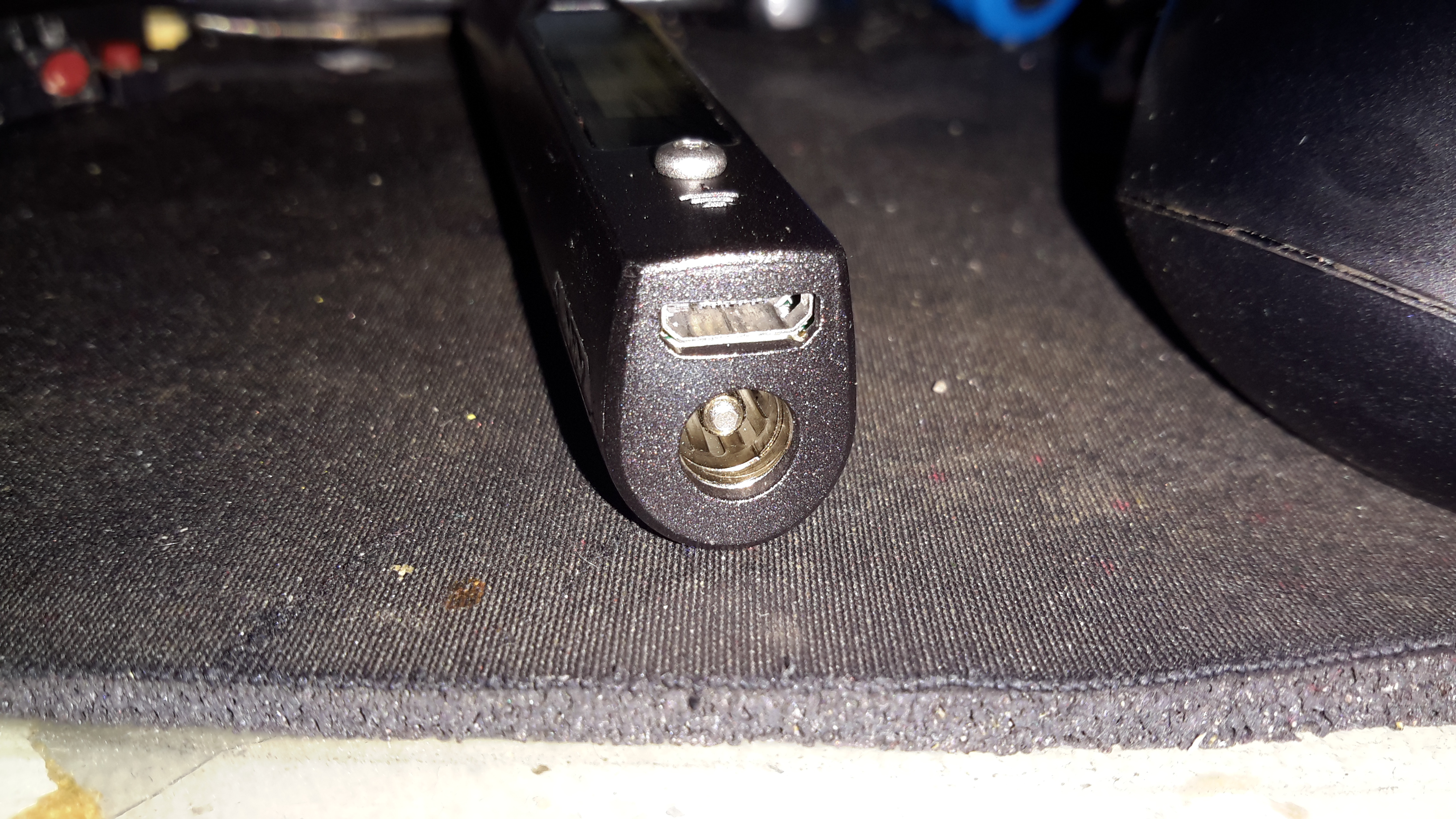
DC Input Jack / USB Port
The bottom end of the iron has the main DC input jack, designed with laptop chargers in mind (DC input range from 10v-24v). Above that is the micro USB port for programming.
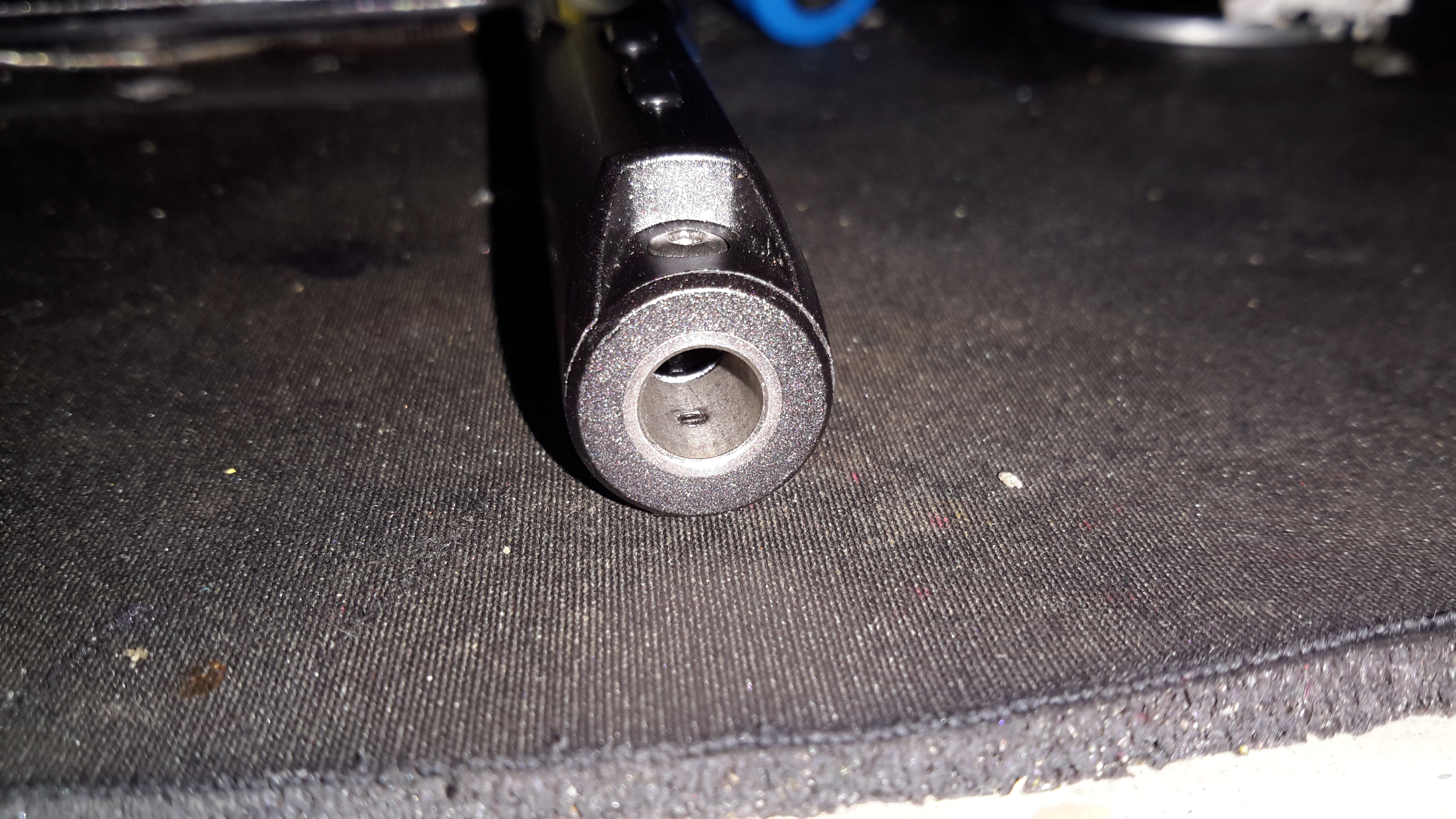
Heating Element Socket
The iron tips slot into the other end, many different tip types & shapes are available. The one supplied was the simple conical tip.
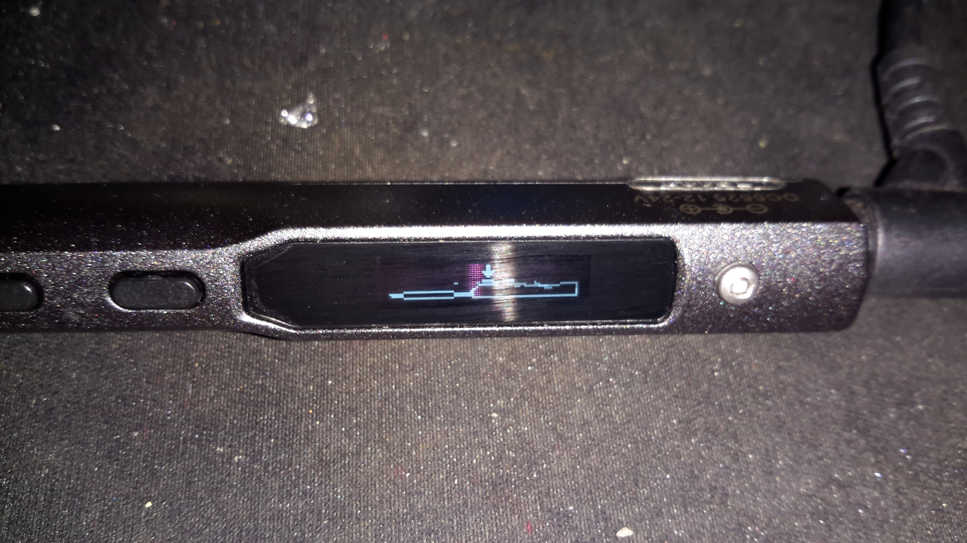
Standby Screen
Plugging the iron into some power gets a standby screen – it doesn’t just start heating immediately, for safety.
Heating
The left hand button starts the heater, which on a 24v input voltage gets to operating temperature well within 10 seconds.
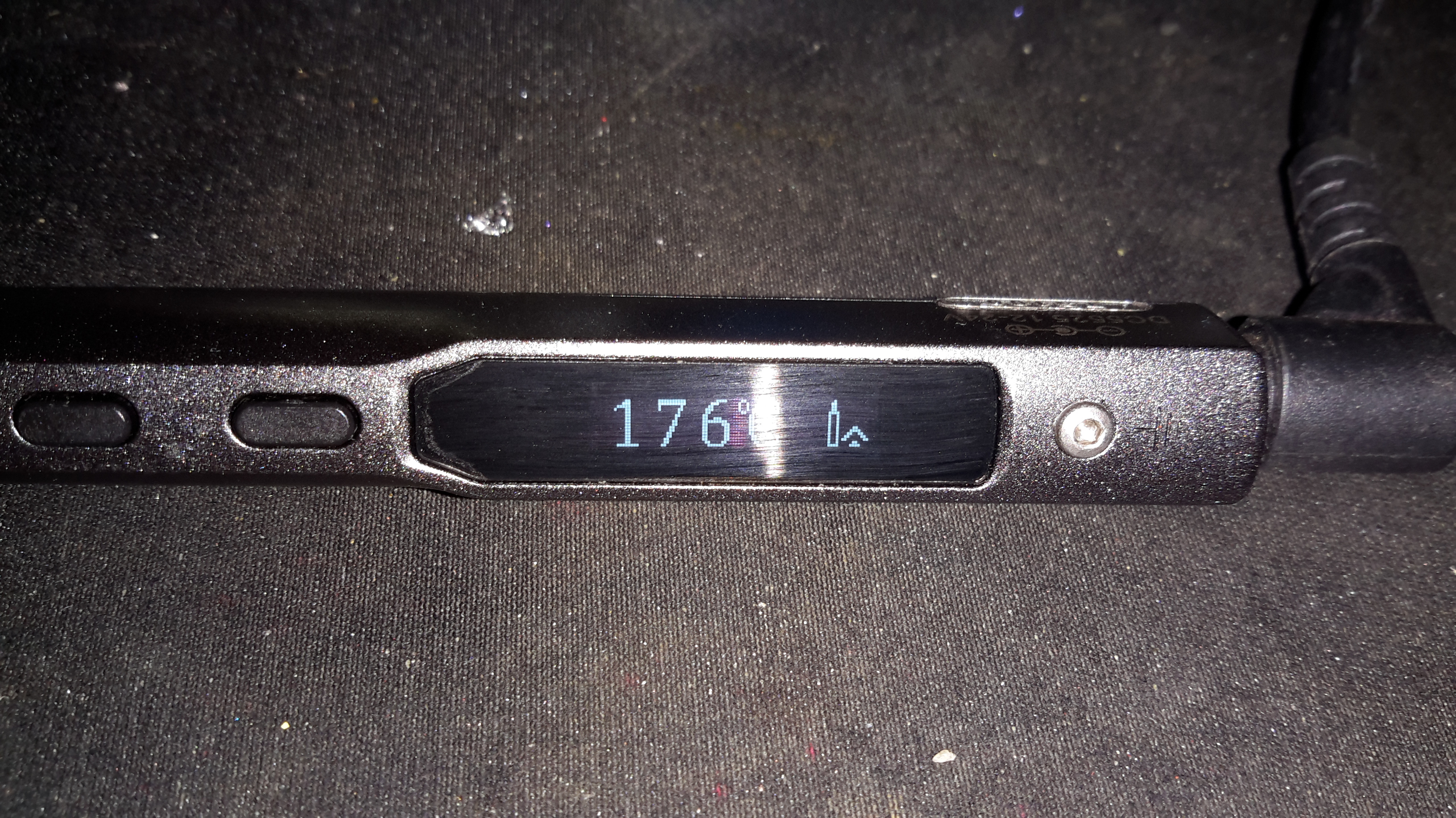
Temperature Stable
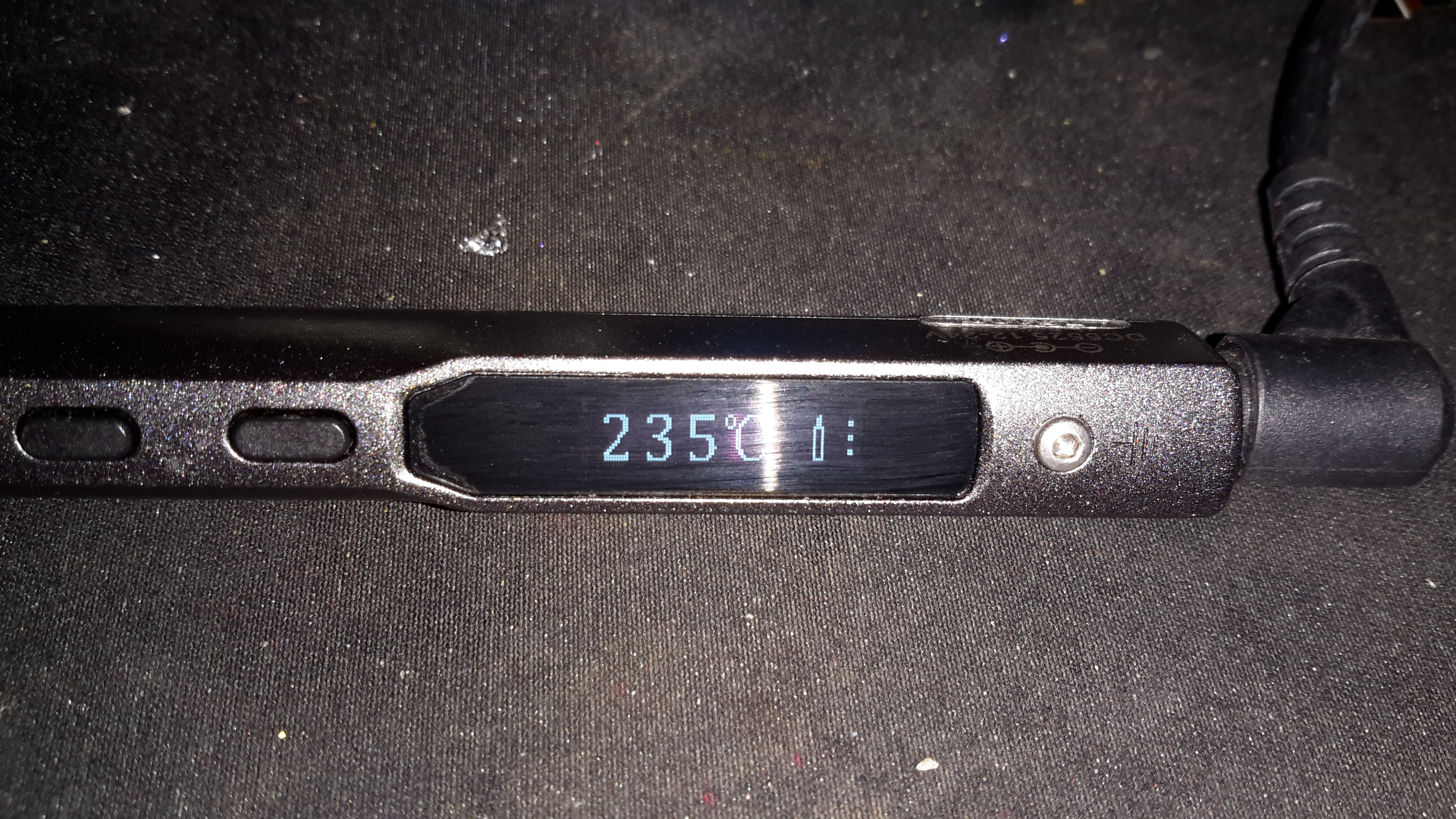
The right hand screen icon changes when the temperature has stabilized. The control PCB has an integrated accelerometer, leaving the iron hot for a few minutes triggers a timeout & it powers down. Once picked up again, the heater instantly restarts.
The operating temperature is adjustable with the pair of buttons, from 100°C to 400°C.
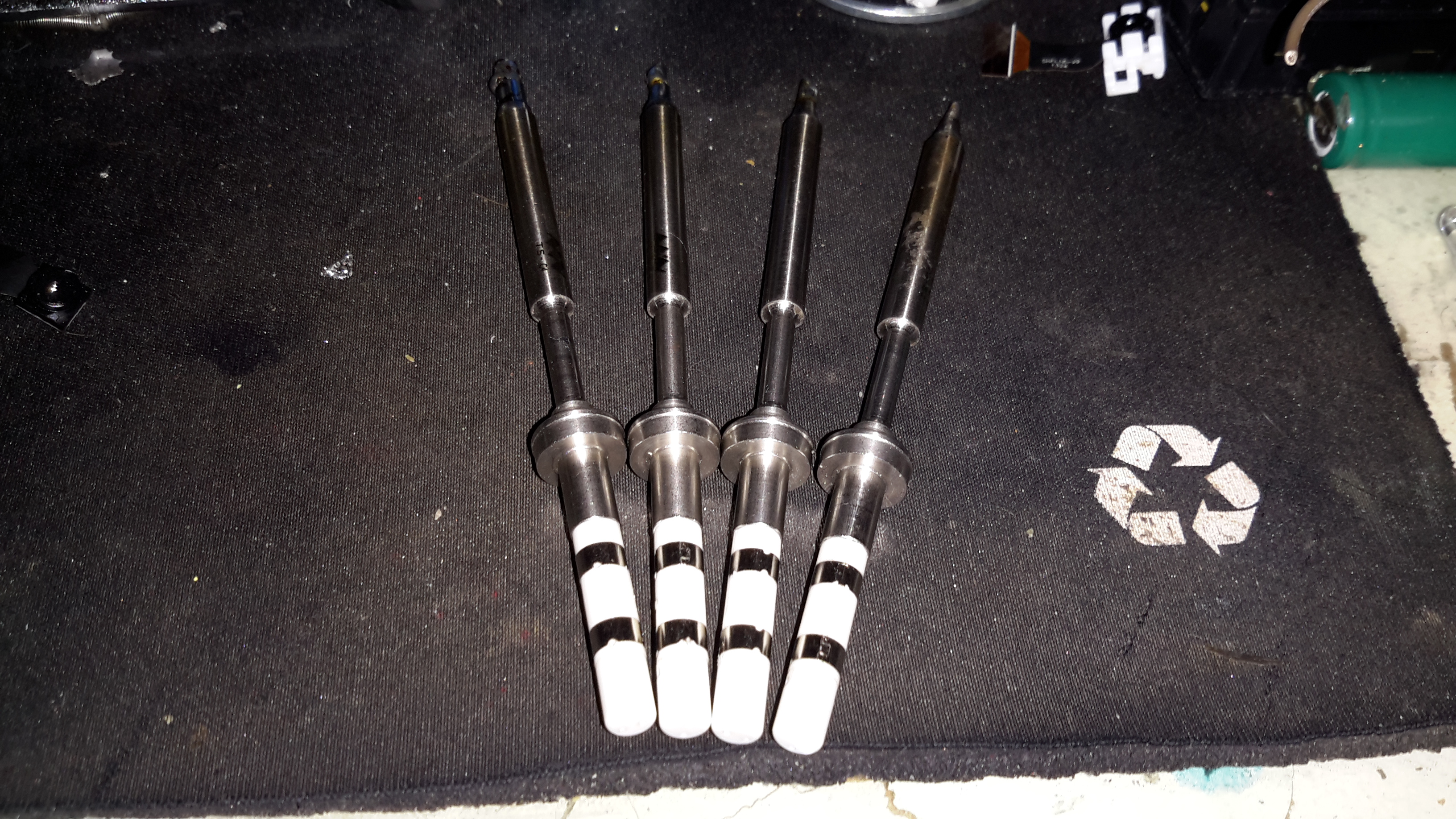
Different Bits
Here’s a selection of bits for the iron. The design is very similar to the Hakko T15 series of irons, but these are a much shorter version. Like the Hakko versions, the actual tips aren’t replaceable, once the bit burns out, the entire assembly is replaced.
TS100 Soldering Iron
Here’s the iron fully assembled. The entire device is about the same length as just the heating element from a Hakko T15!
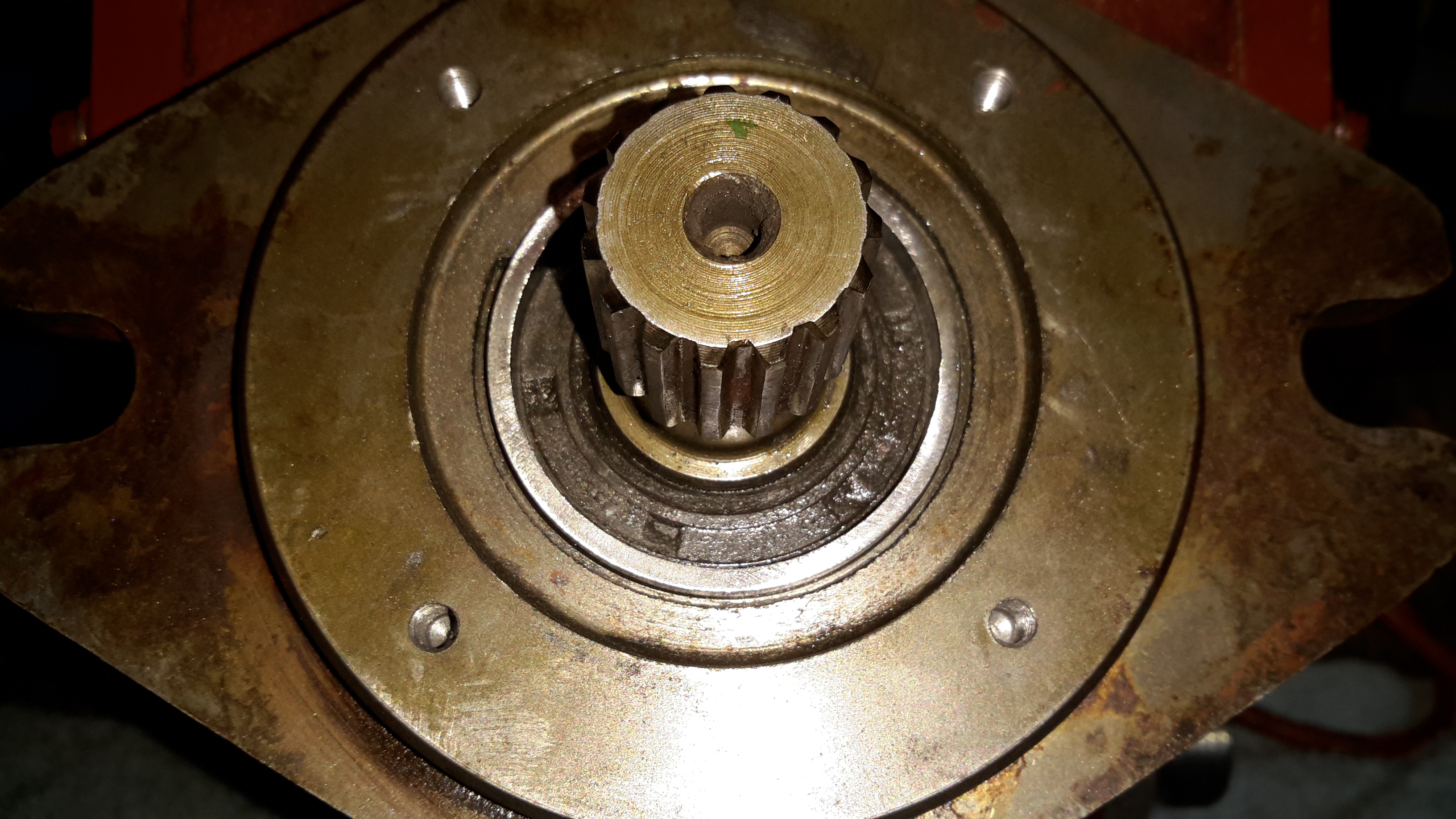
In the process of going through the boat mechanically, ready for this year’s cruising season, some damage was discovered on the face of the main hydraulic propulsion pump that drives the propeller.
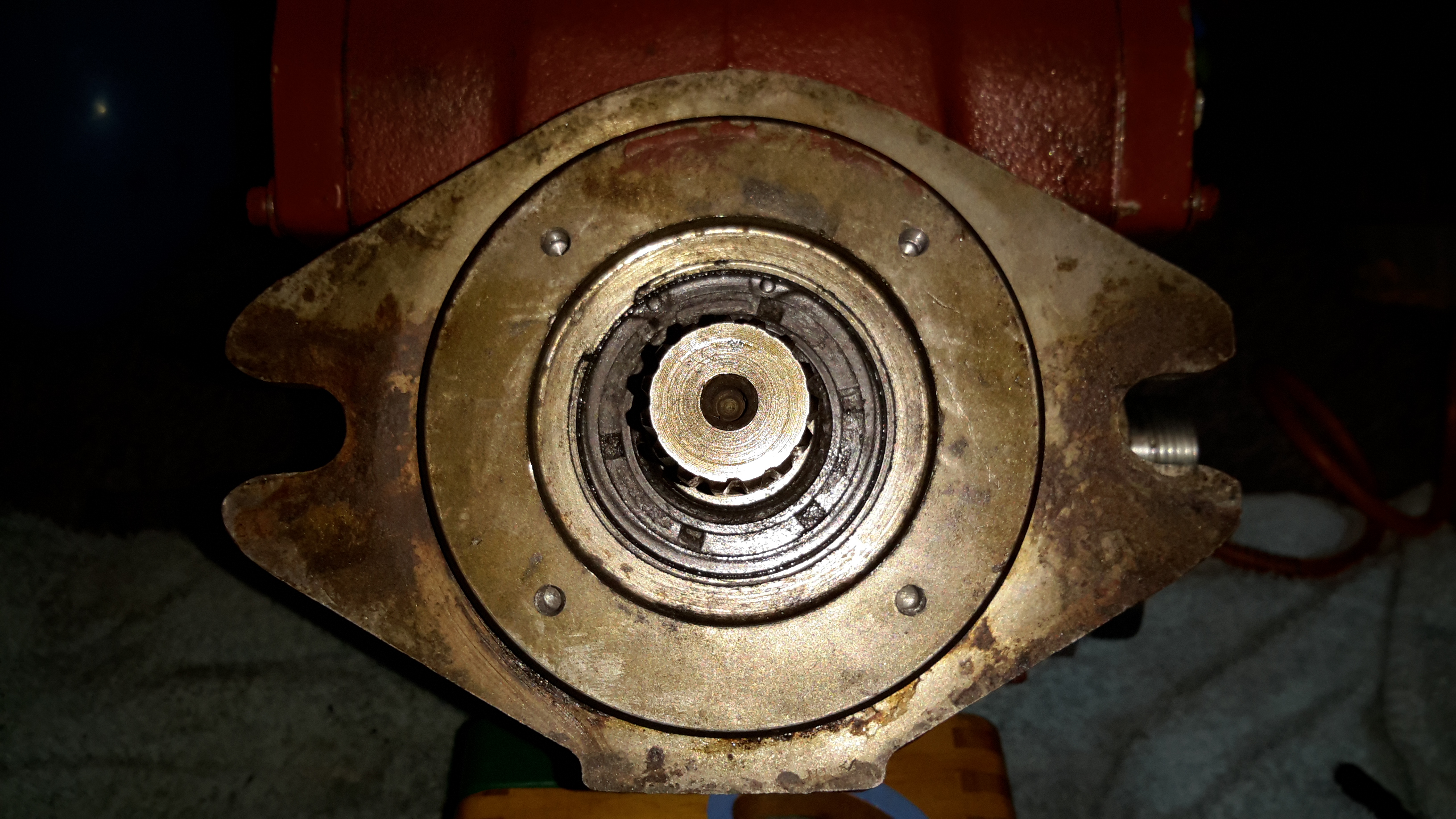
Face Damage
Here’s the front face of the pump, with it’s drive shaft. The circular ridge isn’t supposed to be there, it’s meant to be completely flat.
The central hub of the Centaflex coupling managed to loosen itself on the shaft (they’re pretty badly designed), and when the steel hub moved backward, it ground a very nice recess into the cast iron pump housing.
This managed to get deep enough where it compromised the circlip groove that holds both the oil seal & the mainshaft thrust bearing in place.
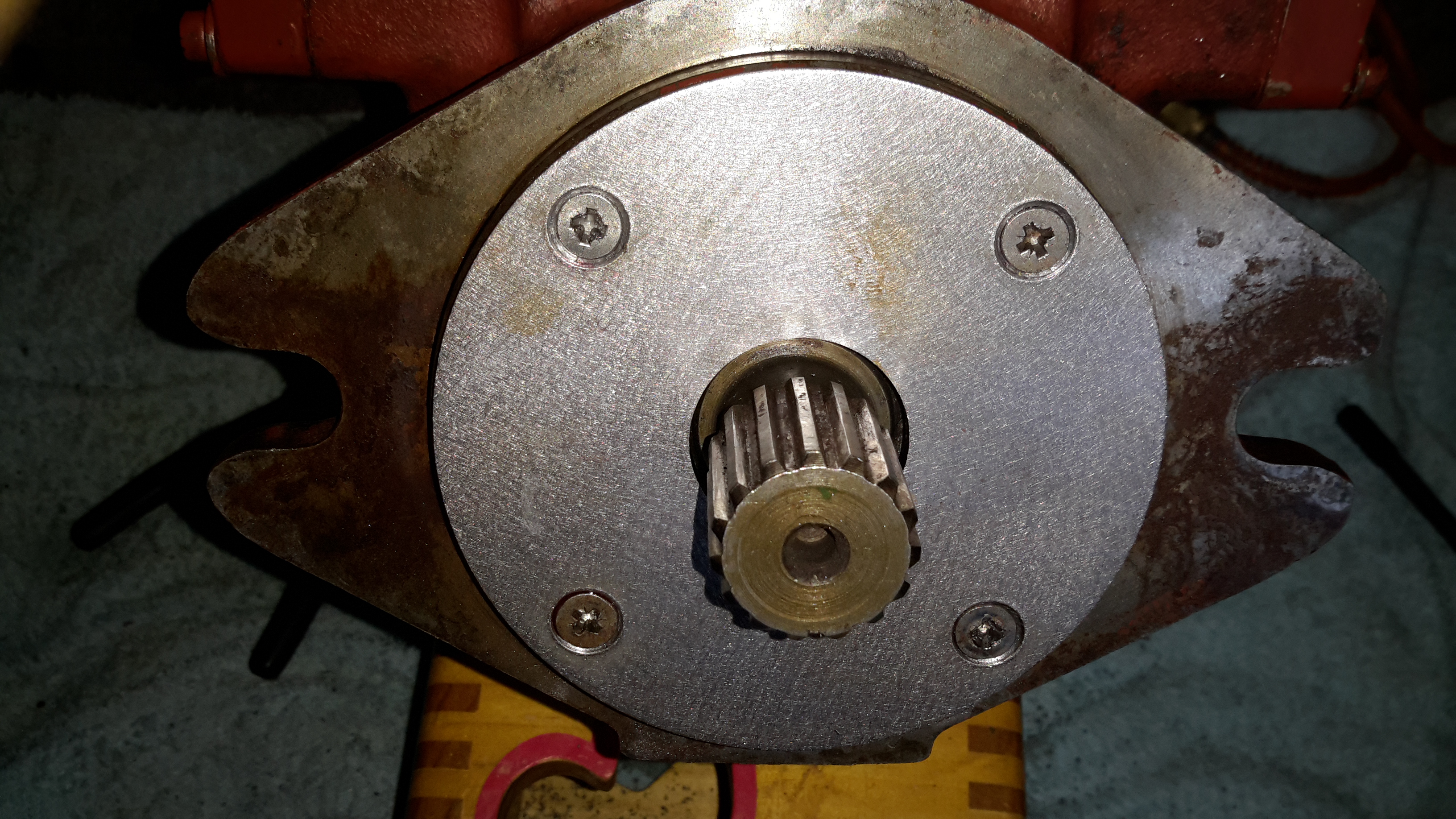
Spacer Ring
To save a considerable amount of cash (replacing the entire base casting of the pump would be hideously expensive), a 6mm ring was machined from steel, to hold the seal in place.
The face of the pump was then drilled & tapped for M5 screws.
Plate Fitted
Above, the repair plate has been fitted, with the spacer ring sandwiched between it & the oil seal, securing everything in place.
Having a replaceable wear plate screwed to the front of the pump also allows for easy future repair if the coupling moves again.
For my latest project, I needed an easier way to paint without messing about with brushes, and the associated marks they leave in a paint job. eBay provided me with a cheap airbrush & compressor.
Airbrush Kit
For less than £30, this kit doens’t look so bad. I’ve never used an airbrush before, but I’ve had no problems with this as yet spraying both water based paints & solvent based paints.
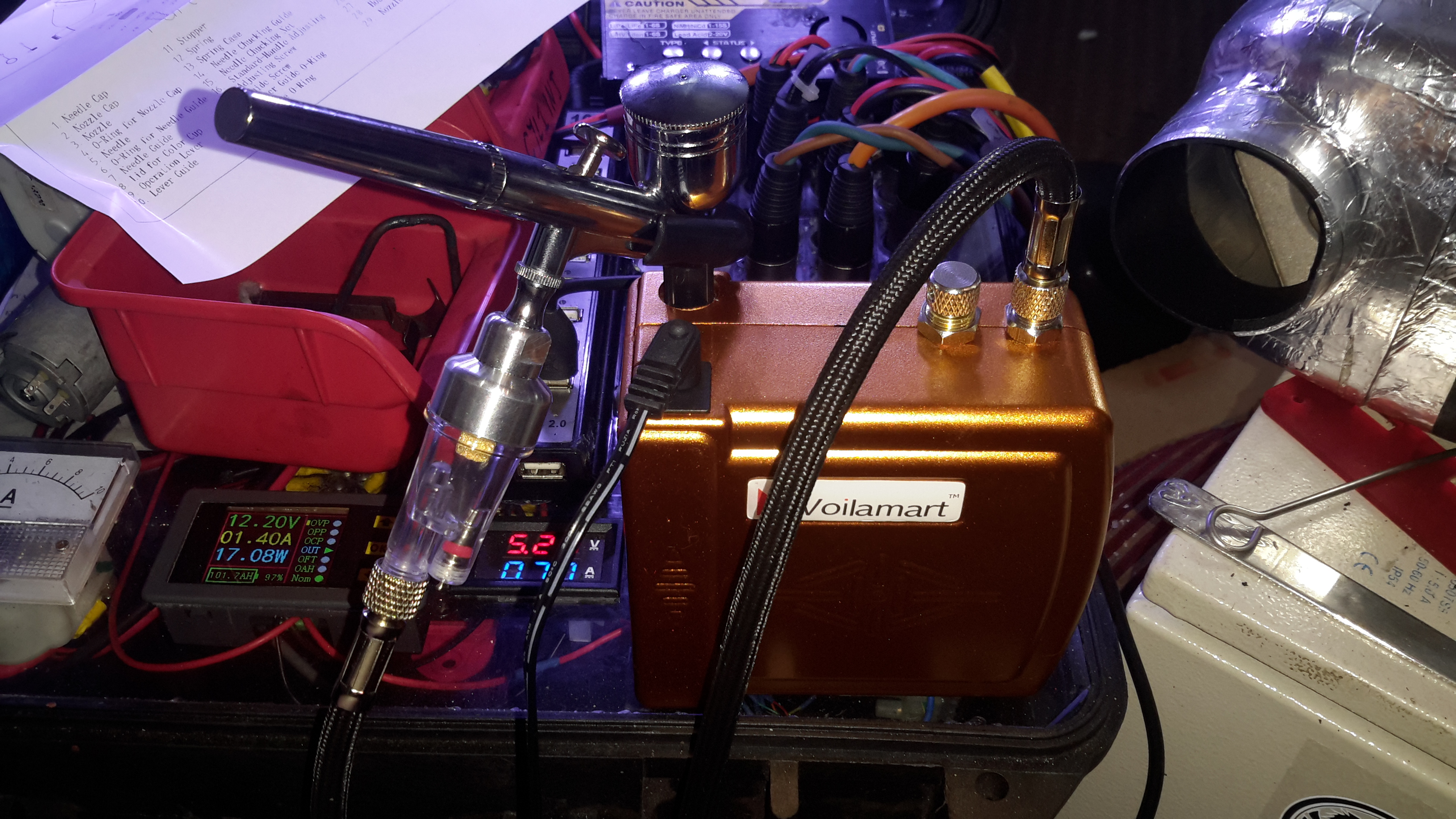
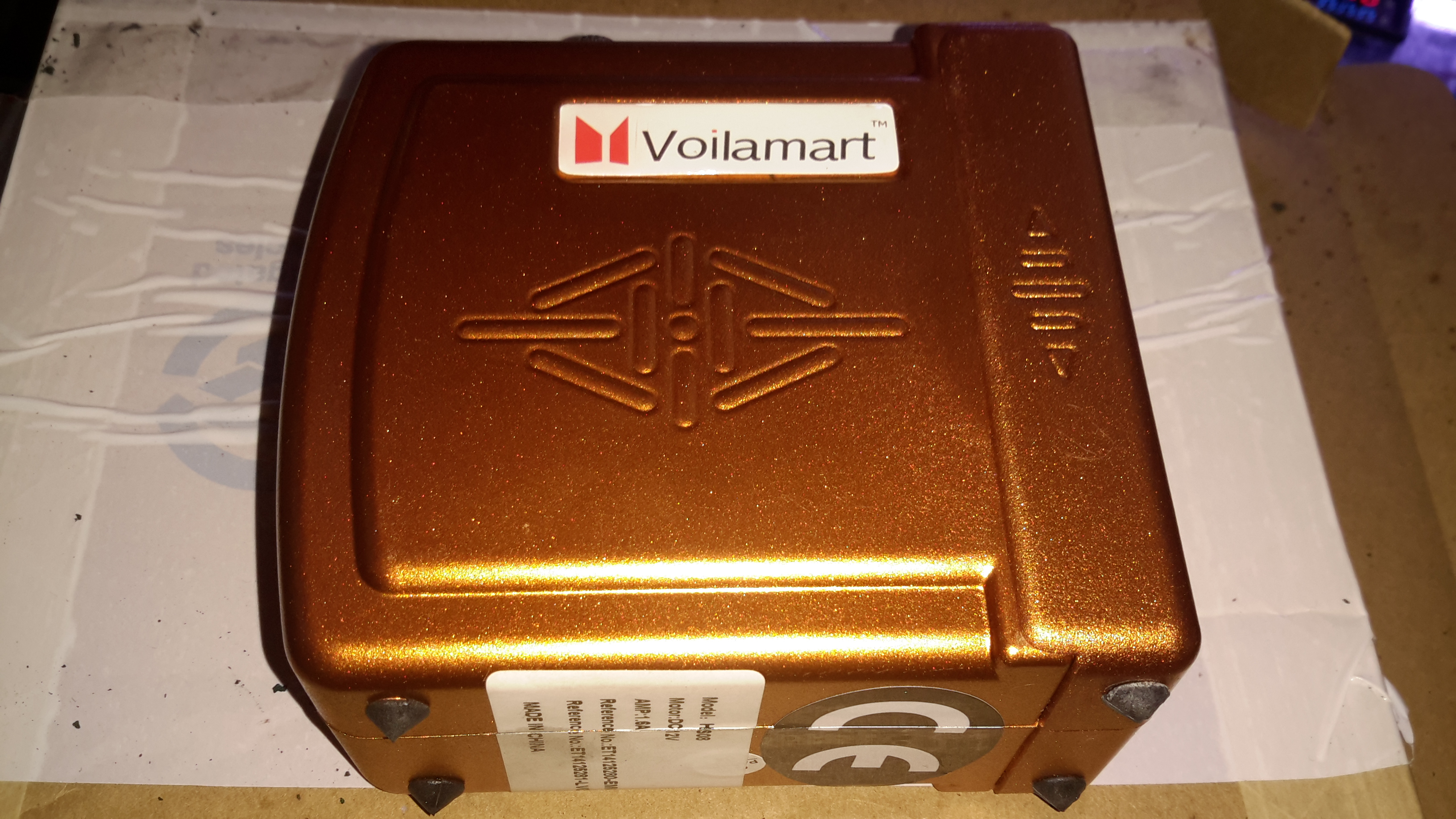
Compressor
Here’s the compressor itself, this runs on 12v & has an output pressure of 1.5 Bar, which is supposed to be adjustable.
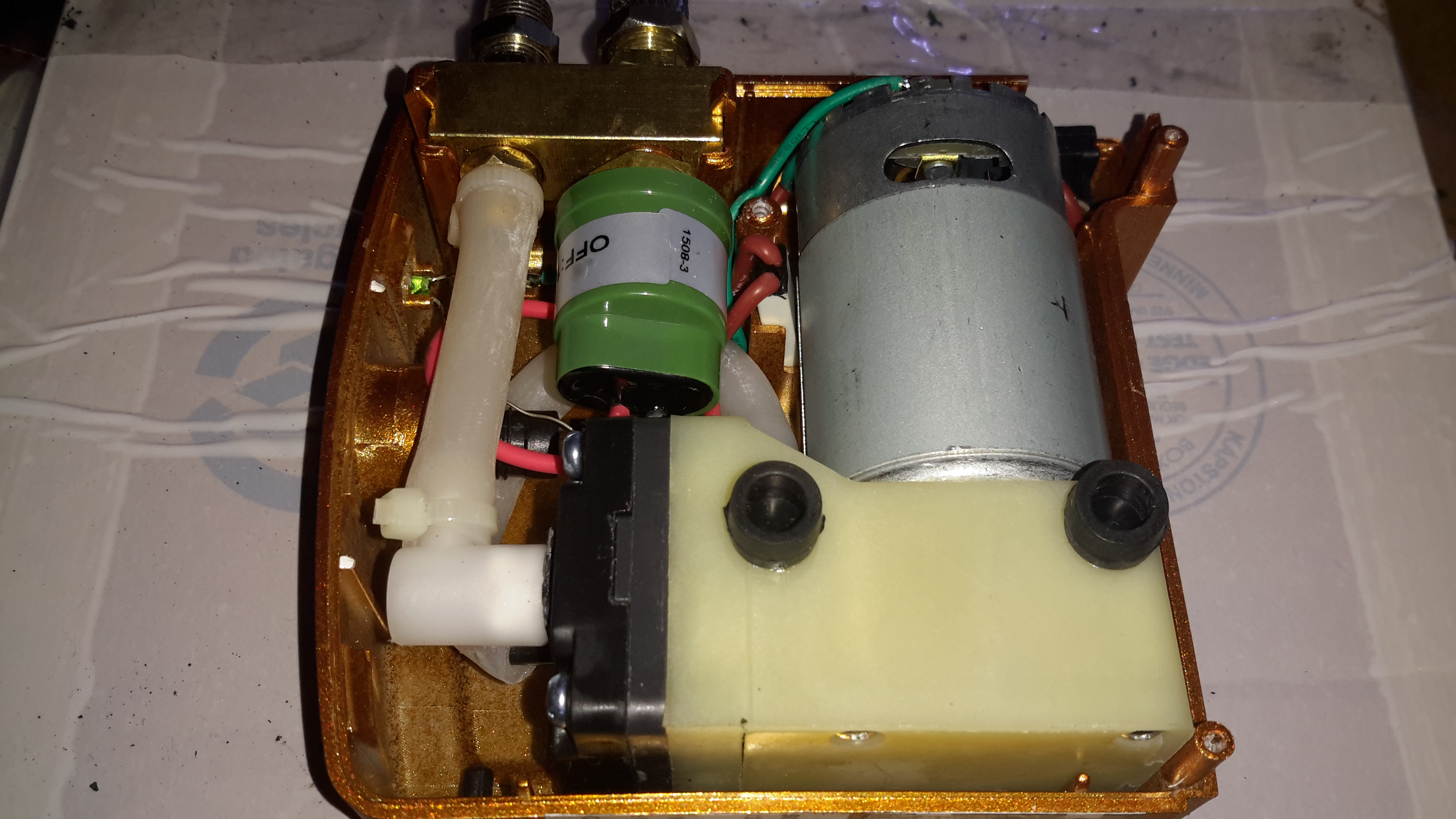
Compressor Internals
Removing a couple of screws reveals the internal components. Nothing much unusual here, a DC diaphragm pump, pressure switch & outlet fittings. There’s also a thermal cutout fitted next to the motor for protection.
The pressure switch attached to the manifold trips at 1.5Bar, keeping the pressure to the brush pretty much constant.
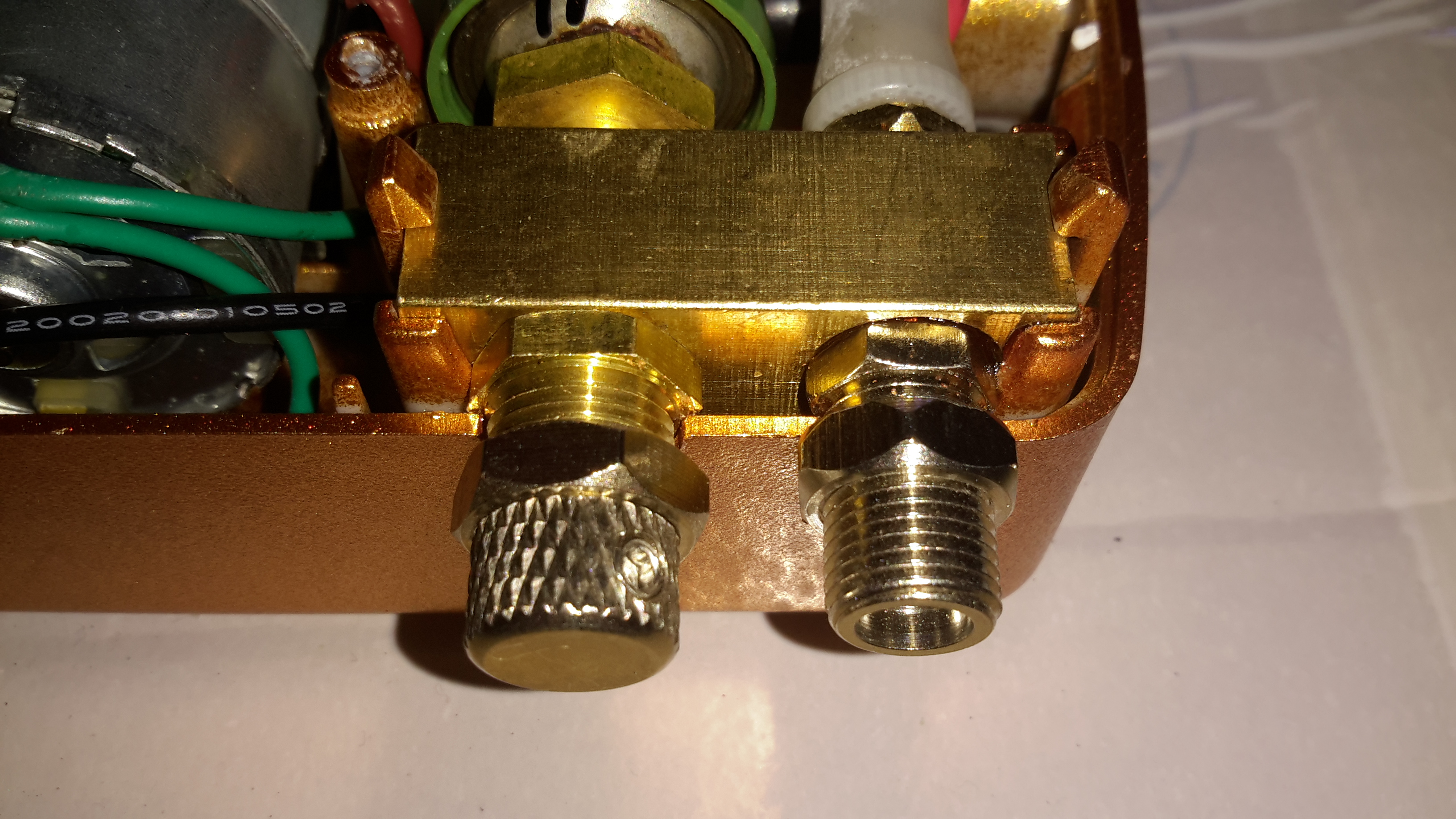
Air Block
Next to the air outlet fitting is an adjustment knob, supposedly for varying the pressure. However it’s just a piss-poorly designed adjustable relief valve that vents to atmosphere. There’s not much of a control range.
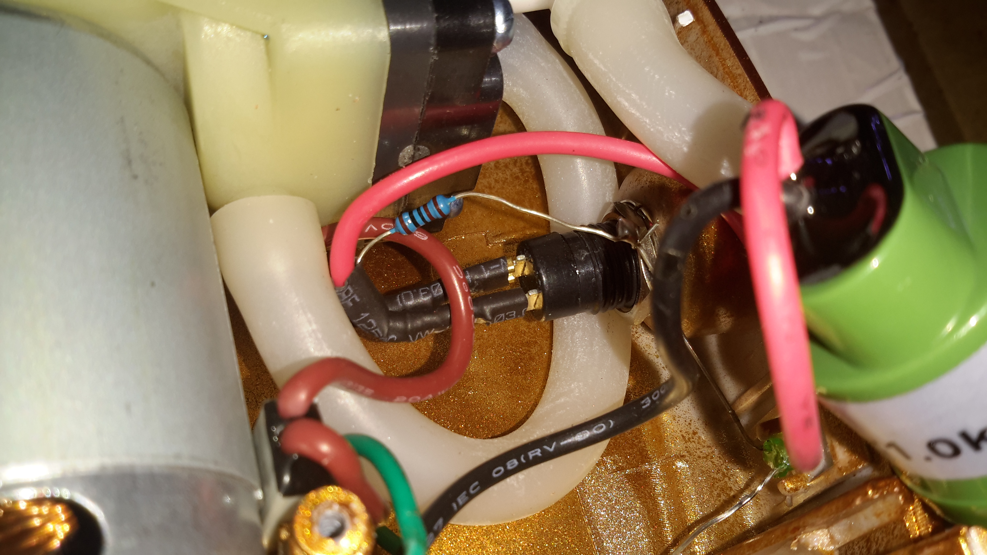
Messy Wiring
The wiring gets a bit messy where the power LED is concerned, with no heatshrink over the solder joints, but it’s adequate.
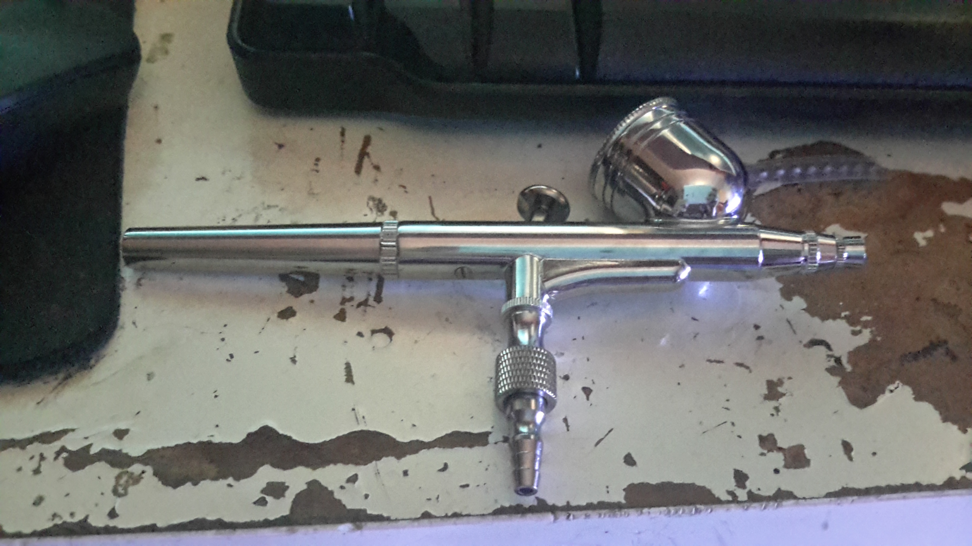
Airbrush
The airbrush itself isn’t too bad. It’s solid Brass, with a very nice Chrome finish. I’m not expecting miracles from a very cheap tool, but it certainly seems to be reasonable.
Water Trap
A moisture trap is supplied for the brush, to prevent water drops being sprayed out with the paint. Very handy.
Just a quick note for the regular (and not so regular) readers:
My server infrastructure is currently going through some migration & upgrade processes, so for the next few days the site might be a little on the slow side, but hopefully I can get everything sorted out quickly!
During this time please bear with the slower than normal response times.
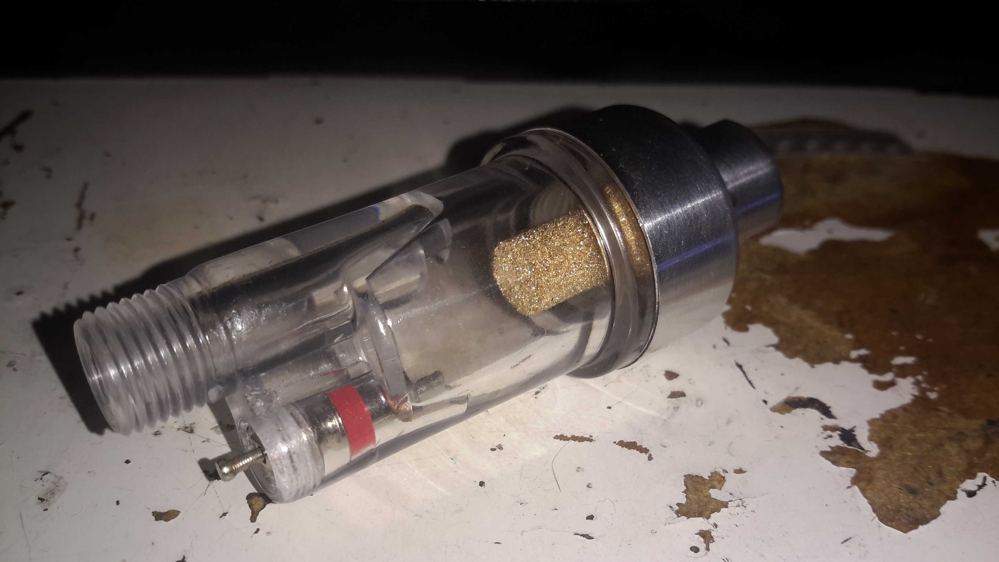
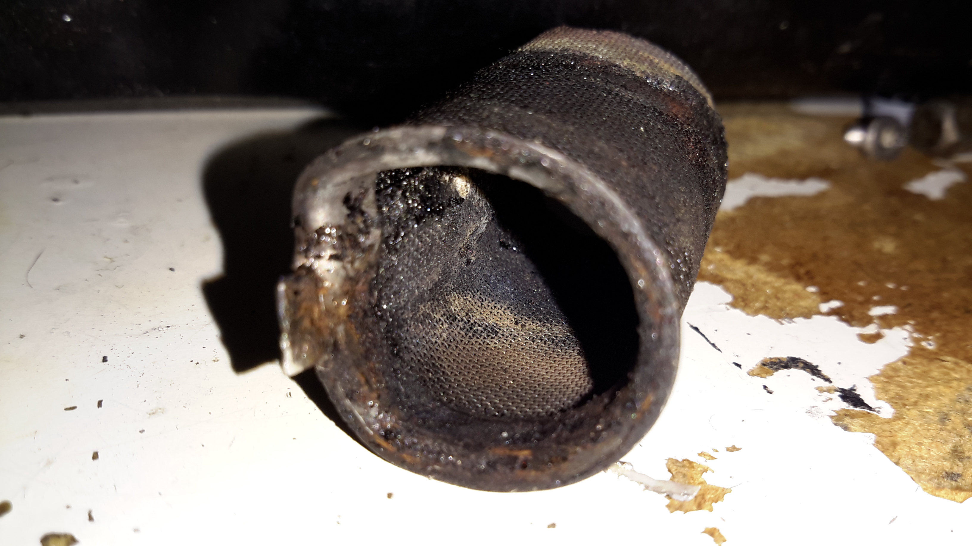
A while ago I posted about the glowplug screens in Eberspacher heaters, and making some DIY ones, as the OEM parts are hideously expensive for a piece of stainless mesh (£13).
Old Screen
Above is the old factory screen that I extracted after only 5 gallons of diesel was run through it, it’s heavily clogged up with carbon & tar. The result of this clogging is a rather slow & smoky start of the heater & surging of the burner while at full power.
It wasn’t as badly stuck in the chamber as some I’ve removed, but extracting it still caused the steel ring to deform, this was after using a scalpel blade to scrape the carbon off the rim.
At the time I did some tests with some spare copper mesh I had to hand, but the problem with copper is that it’s very soft & malleable, so didn’t really hold it’s shape well enough. The factory screens are spot welded to keep them in shape, but as I don’t have a spot welder, I am relying on the mesh having a bit of springiness to keep it in place against the walls of the glowplug chamber.
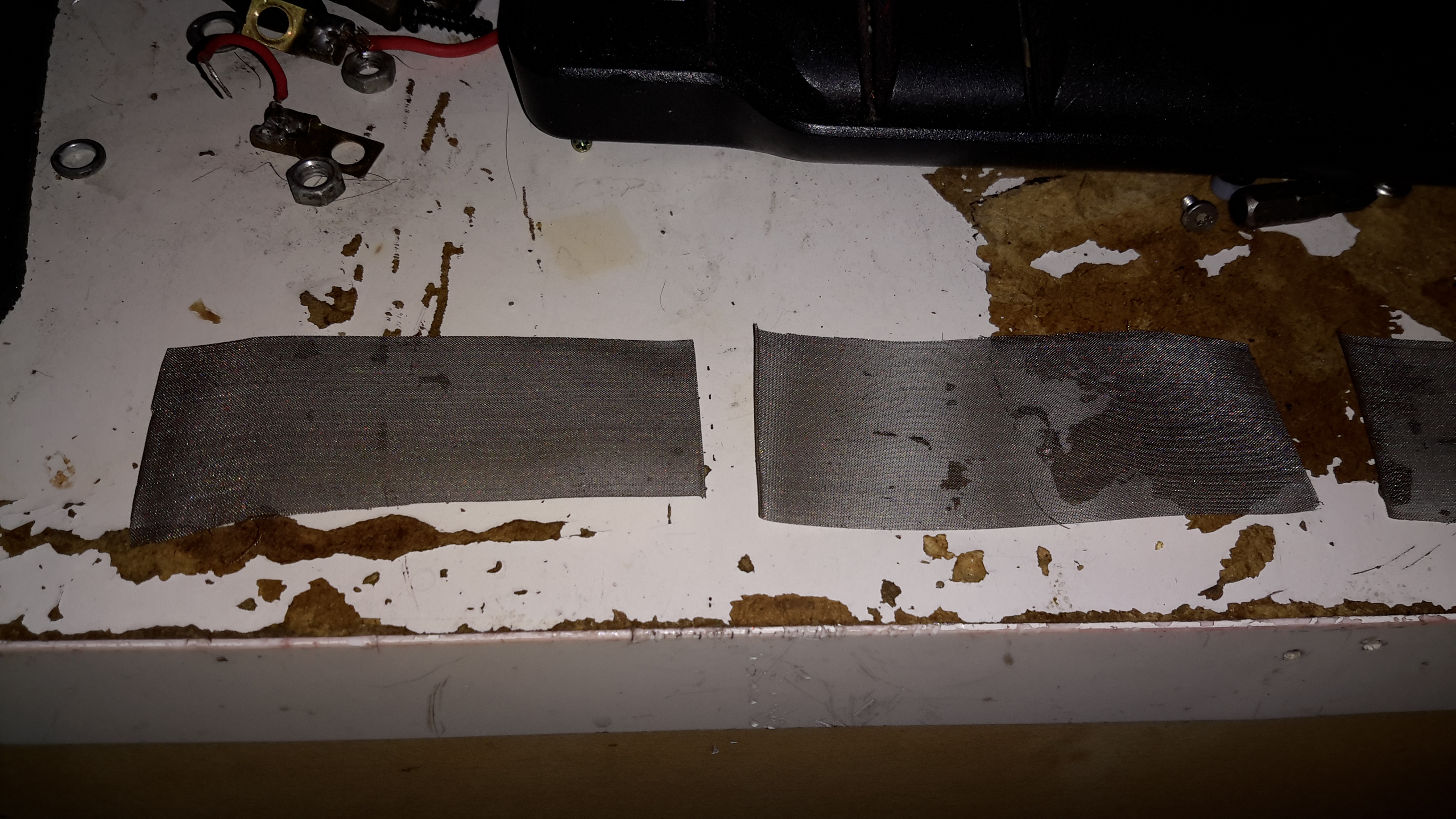
eBay provided a piece of 120 mesh stainless steel mesh, 300mmx300mm for £8. It’s a bit finer than the stock stuff, but appears to work perfectly fine as long as there’s no gunk in the fuel to clog it up.
I cut a strip off the large piece, as wide as the OEM screen, about 32mm. This 300mm long strip is then cut into 4 pieces, each 75mm long. (it’s easily cut with scissors, but mind the stray wires on the edges! They’re very sharp & penetrate skin easily!).
Mesh Screen
These pieces are just the right size to form a complete loop in the glowplug chamber, and the stainless is springy enough so that it doesn’t deform & become loose.
The OEM screen is multiple turns of a more coarse mesh, but the finer mesh size of the screens I’m using means only one turn is required. Multiple turns would probably be too restrictive to fuel flow.
With one of these pieces of mesh in place, the heater starts instantly, without even a wisp of smoke from the exhaust. Burner surging is also eliminated. Even if the service life of my DIY replacement isn’t as long as an OEM screen, the low price for such a large number of replacements certainly offsets that disadvantage!
A piece of mesh from eBay would provide enough material for quite a lot of replacements, and probably more than the service life of the burner itself!
Since this is the 300th post on my blog in the 6 years I’ve been at this, I figured I’d do a post with recent site updates & some news.
Site Look
There haven’t been many updates to the general look of the site for quite a while, with some help of a friend I managed to get a new ticker added to the header, which saves on post count for upcoming projects & posts.
The header image is also dynamic, picking randomly from a collection of images, mostly from previous posts, and a few that started as messing about with a camera & turned out looking quite good.
Site Support
Also added to the site’s look is a Tip Jar on the right hand side, so thankful readers can donate something if I’ve managed to post something remotely helpful ;).
People that know me personally know I hate ads with a passion, and as such ads will have no place on my blog for as long as it’s visible on the intertubes. The site does cost quite a significant (to me anyway) amount of cash to keep going, not to mention time, so any donations would be more than welcome!
Radio-Based Posts
I haven’t done any proper Ham Radio based posts in quite a while, mainly due to me not having anything to share on the subject, unfortunately it can be a damn expensive hobby & there are other things taking priority at the moment. (Apparently eating & warmth are essentials, according to the missus at least ;)).
There is going to be a round-about radio based post shortly though, so my Ham readers stay tuned!
Boating Posts
Now that we’re in the new year, when the weather returns to something remotely tolerable to be outdoors in, there’ll be much more boating related stuff on the cards, not only trips but engineering jobs onboard.
I recently came across these on eBay, so I thought I’d grab one to see how they function, with all the metrics they display, there’s potential here for them to be very useful indeed.
One of the best parts is that no wiring is required between the sensor board & the LCD head unit – everything is transmitted over a 2.4GHz data link using NRF24L01 modules.
Above is the display unit, with it’s colour LCD display. Many features are available on this, & they appear to be designed for battery powered systems.
Monitor PCB
Another PCB handles the current & voltage sensing, so this one can be mounted as close to the high current wiring as possible.
Monitor PCB Microcontroller
The transmitter PCB is controlled with an STM8S003F3 microcontroller from ST Microelectronics. This is a Flash based STM with 8KB of ROM, 1KB of RAM & 10-bit ADC. The NRF24L01 transceiver module is just to the left.
There’s only a single button on this board, for pairing both ends of the link.
Output MOSFET
The high current end of the board has the 0.0025Ω current shunt & the output switch MOSFET, a STP75NF75 75v 75A FET, also from ST Microelectronics. A separate power source can be provided for the logic via the blue terminal block instead of powering from the source being measured.
LCD Unit Rear
Here’s the display unit, only a pair of power terminals are provided, 5-24v wide-range input is catered for.
LCD Unit PCB
Unclipping the back of the board reveals the PCB, with another 2.4GHz NRF24L01 module, and a STM8S005K6 microcontroller in this case. The switching power supply that handles the wide input voltage is along the top edge of the board.
Unfortunately I didn’t get any instruction manual with this, so some guesswork & translation of the finest Chinglish was required to get my head round the way everything works. To make life a little easier for others that might have this issue, here’s a list of functions & how to make them work.
LCD Closeup
On the right edge of the board is the function list, a quick press of the OK button turns a function ON/OFF, while holding it allows the threshold to be set.
When the output is disabled by one of the protection functions, turning that function OFF will immediately enable the output again.
The UP/DOWN buttons obviously function to select the desired function with the cursor just to the left of the labels. Less obviously though, pressing the UP button while the very top function is selected will change the Amp-Hours display to a battery capacity icon, while pressing DOWN while the very bottom function is selected will change the Watts display to Hours.
The round circle to the right displays the status of a function. Green for OK/ON Grey for FAULT/OFF.
OVP: Over voltage protection. This will turn off the load when the measured voltage exceeds the set threshold.
OPP: Over power protection. This function prevents a load from pulling more than a specified number of watts from the supply.
OCP: Over current protection. This one’s a little more obvious, it’ll disable the output when the current measured exceeds the specified limit.
OUT: This one is the status of the output MOSFET. Can also be used to manually enable/disable the output.
OFT: Over time protection. This one could be useful when charging batteries, if the output is enabled for longer than the specified time, the output will toggle off.
OAH: Over Amp-Hours protection. If the counted Amp-Hours exceeds the set limit, the output will be disabled.
Nom: This one indicates the status of the RF data link between the modules, and can be used to set the channel they operate on.
Pairing is achieved by holding the OK button, selecting the channel on the LCD unit, and then pressing the button on the transmitter board. After a few seconds, (it appears to scan through all addresses until it gets a response) the display will resume updating.
This function would be required if there are more than a single meter within RF range of each other.
I’ve not yet had a proper play with all the protection functions, but a quick mess with the OVP setting proved it was very over-sensitive. Setting the protection voltage to 15v triggered the protection with the measured voltage between 12.5v-13.8v. More experimentation is required here I think, but as I plan to just use these for power monitoring, I’ll most likely leave all the advanced functions disabled.
Tip Jar
If you’ve found my content useful, please consider leaving a donation by clicking the Tip Jar below!
All collected funds go towards new content & the costs of keeping the server online.